Embed Size (px)
Citation preview
1
1
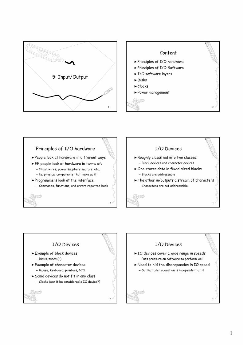
5: Input/Output
2
Content
►Principles of I/O hardware►Principles of I/O Software►I/O software layers►Disks►Clocks►Power management
3
Principles of I/O hardware
►People look at hardware in different ways►EE people look at hardware in terms of:
– Chips, wires, power suppliers, motors, etc.– i.e. physical components that make up it
►Programmers look at the interface– Commands, functions, and errors reported back
4
I/O Devices
►Roughly classified into two classes:– Block devices and character devices
►One stores data in fixed-sized blocks– Blocks are addressable
►The other in/outputs a stream of characters– Characters are not addressable
5
I/O Devices
►Example of block devices:– Disks, tapes (?)
►Example of character devices:– Mouse, keyboard, printers, NIS
►Some devices do not fit in any class– Clocks (can it be considered a IO device?)
6
I/O Devices
►IO devices cover a wide range in speeds– Puts pressure on software to perform well
►Need to hid the discrepancies in IO speed– So that user operation is independent of it
2
7
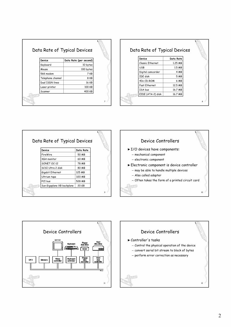
Data Rate of Typical Devices
400 KBScanner
100 KBLaser printer
16 KBDual ISDN lines
8 KBTelephone channel
7 KB56K modem
100 bytesMouse
10 bytesKeyboard
Data Rate (per second)Device
8
Data Rate of Typical Devices
1.25 MBClassic Ethernet
1.5 MBUSB
16.7 MBEIDE (ATA-2) disk
16.7 MBISA bus
12.5 MBFast Ethernet
6 MB40x CD-ROM
5 MBIDE disk
4 MBDigital camcorder
Data RateDevice
9
Data Rate of Typical Devices
50 MBFireWire
60 MBXGA monitor
78 MBSONET OC-12
20 GBSun Gigaplane XB backplane
528 MBPCI bus
320 MBUltrium tape
125 MBGigabit Ethernet
80 MBSCSI Ultra 2 disk
Data RateDevice
10
Device Controllers
►I/O devices have components:– mechanical component – electronic component
►Electronic component is device controller– may be able to handle multiple devices– Also called adapter– Often takes the form of a printed circuit card
11
Device Controllers
12
Device Controllers
►Controller's tasks– Control the physical operation of the device– convert serial bit stream to block of bytes– perform error correction as necessary
3
13
Device Controllers
►Exchange data with CPU via registers►By writing into these registers
– OS can command it to deliver or accept data– Or switch the device on or off
►By reading from the registers– OS can learn the status of the device
14
Device Controllers
►In addition, controllers often have buffers– Which the OS can read or write
►Ex: a video controller may have Video RAM– A data buffer programs can write or read
15
I/O Approaches
►3 ways for CPU to communicates with the control registers and its device buffers– Dedicated I/O– Memory-mapped I/O– Hybrid
16
Dedicated I/O
►Each control register assigned an IO port– i.e. an 8 or 16 bit integer
►IO port and memory are separate►OS uses special instructions to read/write
– IN REG, PORT for reading from the device– OUT PORT, REG for writing to the device
17
Dedicated I/O
►Computers use dedicated I/O include– Early computers, mainframes (IBM 360/370)
►Problems with this approach?– Controls are at low-level– No high level languages has IN/OUT operations– Protections can be problematic
18
Memory-Mapped I/O
►An alternative to Dedicated I/O►Each control register is assigned a unique
memory address– Input/output done by reading/writing to the
designated memory addresses– Just like a ordinary memory access
►Introduced in PDP-11 computer
4
19
Hybrid Approach
►Memory-mapped data buffer►Dedicated I/O ports►For example, Pentium use address:
– 640K to 1M for device data buffers– 0 to 64K for I/O ports
20
Memory-Mapped I/O
memory
I/O ports
0xFFFF…
0
2 address 1 address space 2 address space
(a) (b) (c)
Dedicated I/O Memory-mapped I/O Hybrid
21
Memory-Mapped I/O
►Problems for memory-mapped I/O?►Cache cause problems►For 1-bus system, both memory and device
have to examine addresses on the bus►For system with multiple memory buses:
– Devices may not see the addresses on the bus
22
Memory-Mapped I/O
A dual-bus memory architecture
(a) A single-bus architecture
23
Memory-Mapped I/O
►Many ways to solve the multiple buses issue►Fail and try
– If memory fails to respond, try other buses
►Snooping– A snooping device on the bus passes to devices
►Address filtering
24
Address Filtering in Pentium
5
25
Direct Memory Access
►Memory-mapped or not, CPU needs to address controllers to exchange data
►Can request data one byte at a time►Or request data in bulk
– This is accomplished via DMA
26
Direct Memory Access
►Can use only if there is DMA controller►DMA controller can be built in device
controller– requires one DMA controller for each device
►More commonly, a single DMA controller– One the parentboard
27
Direct Memory Access
Operation of a DMA transfer28
Direct Memory Access
►DMA controller vary in sophistication►Simplest one handles 1 transfer at a time►Complex one have multiple channels
– With each channel deals with one device
29
Issues with DMA
►How to access the bus?– Cycle stealing or burst mode?
►Where to store the data?– Directly into memory or in DMA buffer?
►How to address the memory?– Virtual or physical address?
30
Pros and Cons of DMA
►+ free up CPU►- Use CPU instead of DMA if:
– Device speed is fast– if CPU has nothing else to do– Save money (by getting rid of DMA)
6
31
Principles of I/O Software
►Device independence is a key concept OS►Program should access all I/O devices in
same or similar ways– i.e. without specify the device in advance
►Ex: when reading a file, do not care if– The file is in floppy, disk, or CD-ROM
32
Principles of I/O Software
►This is the responsibility of I/O software
33
Goals of I/O Software
►Device independence– programs can access any I/O device – without specifying device in advance – (floppy, hard drive, or CD-ROM)
34
Goals of I/O Software
►Uniform naming– name of a file or device a string or an integer– not depending on which machine
►Error handling– handle as close to the hardware as possible
35
Goals of I/O Software
►Synchronous vs. asynchronous transfers– blocked transfers vs. interrupt-driven
►Buffering– data coming off a device cannot be stored in
final destination right away
36
Goals of I/O Software
►Sharable vs. dedicated devices►Make dedicated devices appear sharable►Some devices are not sharable►Disks are sharable►Printer can be made sharable►Tape drives would not be sharable
7
37
Programmed I/O
►Three different ways to perform I/O►Programmer I/O is the simplest►Interrupt-driven is the most common►DMA I/O used to improve efficiency
38
Programmed I/O
►CPU wait for the I/O to complete►This is called Polling or Busy waiting
– Very bad– But simple to program
39
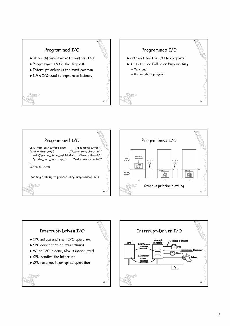
Programmed I/OCopy_from_user(buffer,p,count) /*p is kernel buffer */For (i=0;i<count;i++) { /*loop on every character*/
while(*printer_status_reg!=READY); /*loop until ready*/*printer_data_register=p[i]; /*output one character*/
}Return_to_user();
Writing a string to printer using programmed I/O
40
Programmed I/O
Steps in printing a string
41
Interrupt-Driven I/O
►CPU setups and start I/O operation►CPU goes off to do other things►When I/O is done, CPU is interrupted►CPU handles the interrupt►CPU resumes interrupted operation
42
Interrupt-Driven I/O
8
43
Interrupt-Driven I/O
►Code executed when print system call is madeCopy_from_user(buffer,p,count)Enable_interrupts();while(*printer_status_reg!=READY);
*printer_data_register=p[0];Scheduler();
44
Interrupt-Driven I/O►Interrupt service procedure
If(count==0){unblock_user();
} else {*printer_data_register=p[i];count-count-1; i=i+1;
}acknowledge interrupt(); return_from_intertupt();
45
I/O Using DMA
►An obvious con for interrupt-driven I/O is the frequent interrupts
►The solution is to use DMA
46
I/O Using DMA
►Idea is to let DMA controller handle the I/O one character at a time
►In other words, busy wait with DMA
47
I/O Using DMA
►Printing a string using DMA
Copy_from_user(buffer,p,count); acknowledge_interrupt();Set_up_DMA_controller(); unblock_user();Scheduler(); return_from_interrupt);
(a) (b)
48
I/O Software Layers
►IO software are organized into layers►Each layer has a:
– Well-defined function to perform– Well-defined interface to the adjacent layer
►Exact division differs by systems
9
49
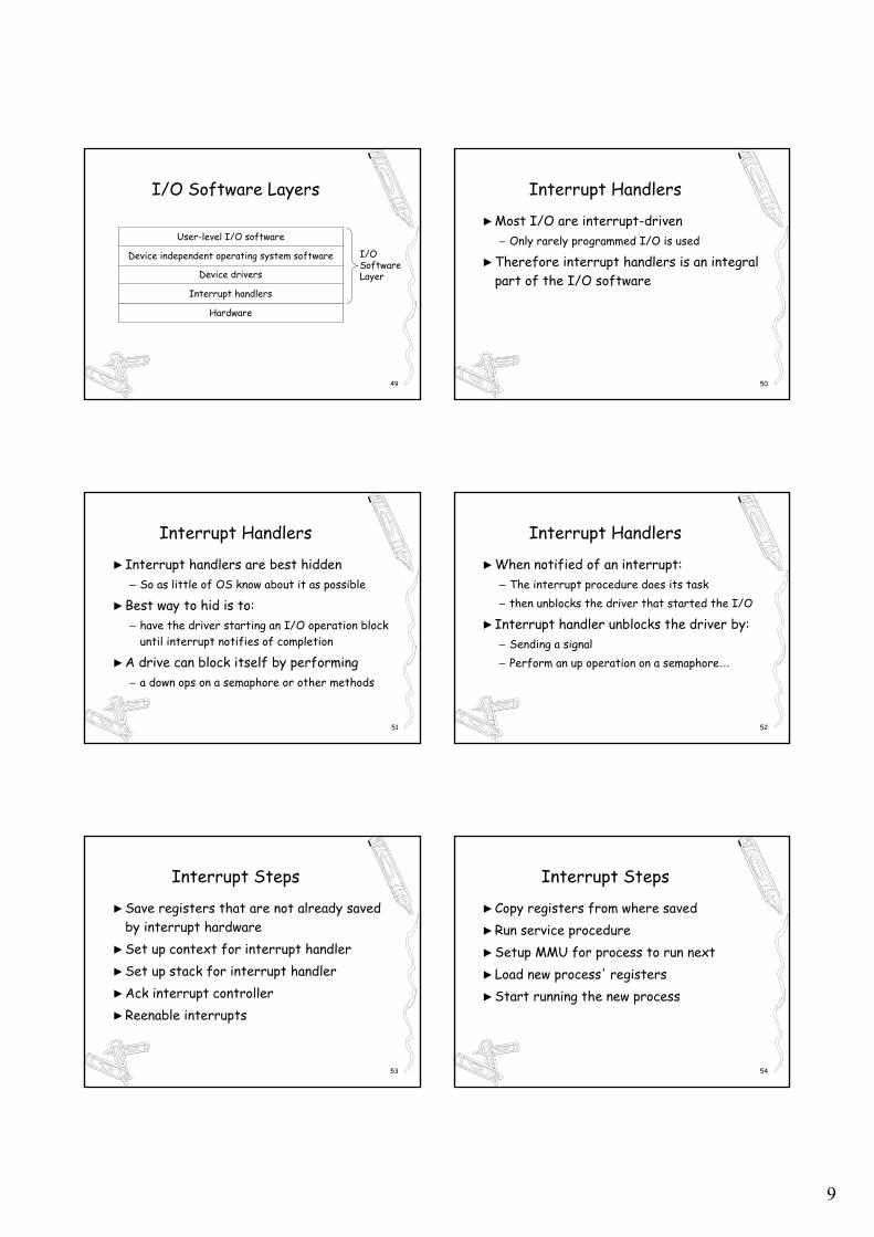
I/O Software Layers
Hardware
Interrupt handlers
Device drivers
Device independent operating system software
User-level I/O software
I/OSoftwareLayer
50
Interrupt Handlers
►Most I/O are interrupt-driven– Only rarely programmed I/O is used
►Therefore interrupt handlers is an integral part of the I/O software
51
Interrupt Handlers
►Interrupt handlers are best hidden– So as little of OS know about it as possible
►Best way to hid is to:– have the driver starting an I/O operation block
until interrupt notifies of completion
►A drive can block itself by performing– a down ops on a semaphore or other methods
52
Interrupt Handlers
►When notified of an interrupt:– The interrupt procedure does its task– then unblocks the driver that started the I/O
►Interrupt handler unblocks the driver by:– Sending a signal– Perform an up operation on a semaphore…
53
Interrupt Steps
►Save registers that are not already saved by interrupt hardware
►Set up context for interrupt handler►Set up stack for interrupt handler►Ack interrupt controller►Reenable interrupts
54
Interrupt Steps
►Copy registers from where saved►Run service procedure►Setup MMU for process to run next►Load new process' registers►Start running the new process
10
55
Device Drivers
►The software that talks to the controller►Device specific►Tailored to individual device characteristics►Written by device manufacturers►Part of the OS Kernel
56
Device Drivers
►Know about the details of the devices►Disk driver knows about sectors, tracks,
cylinders, heads, arm motions, motor drives►Mouse driver knows about button pressed
57
Device Drivers
►Device drivers’ tasks:►Accept abstract read/write requests
– from device-independent software above it
►See that read/write requests carried out►Initialize device, turn on/off device►Power management for device
58
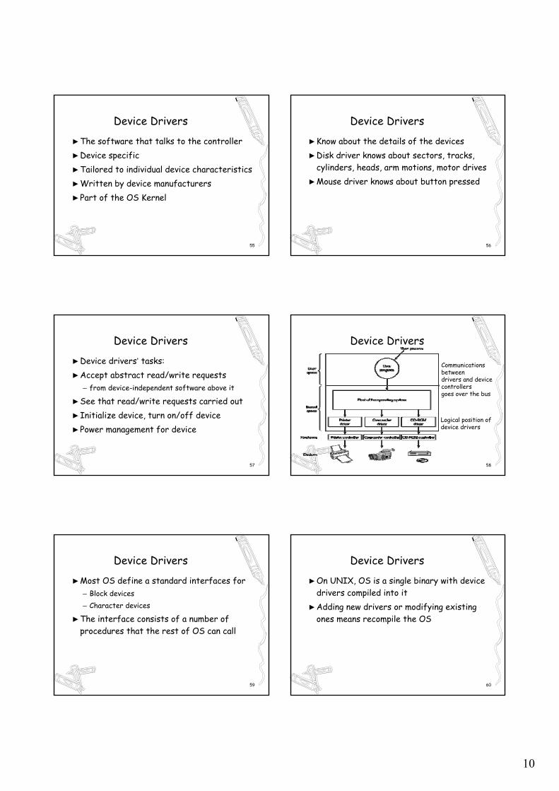
Device Drivers
Communications between drivers and device controllers goes over the bus
Logical position of device drivers
59
Device Drivers
►Most OS define a standard interfaces for– Block devices– Character devices
►The interface consists of a number of procedures that the rest of OS can call
60
Device Drivers
►On UNIX, OS is a single binary with device drivers compiled into it
►Adding new drivers or modifying existing ones means recompile the OS
11
61
Device Drivers
►In Windows, drivers are dynamically loaded
62
Device Driver Operation
►Checking input parameters to see if valid– If not, report error
►Translate abstract request to concrete– convert a linear block # to head, track, sector...
►Check device is busy– If yes, request queued for later process
63
Device Driver Operation
►Check hardware status to see if the request can be handled now– May need to turn on the device– Or start a motor
►Control the operation by issuing a sequence of commands to the device registers
64
Device Driver Operation
►Block itself and wait for interrupt►Upon waking up, check for I/O errors►Pass data to the layer above it►Return status to its caller
65
Device-Independent I/O Software
►Some I/O software is device specific►But some are not!►Basic function is to:
– Perform IO ops that are common to all devices– Provide uniform interface to user-level software
66
Functions of the device-independent I/O software
Providing a deice-independent block size
Allocating and releasing dedicate devices
Error reporting
Buffering
Uniform interfacing for device drivers
Device-Independent I/O Software
12
67
Device-Independent I/O Software
►Exact boundary between drivers & device independent software is device dependent
68
Uniform Interfacing
►Make all devices look the same or similar– By standardizing driver interface
►Specify the functions a driver provides►Specify kernel function a driver can call
69
Uniform Interfacing
Without a standard driver interface With a standard driver interface
70
Buffering
►Buffering is indispensable in I/O►It speed up the data transfer►It synchronize between CPU and devices►It prevents overflow
71
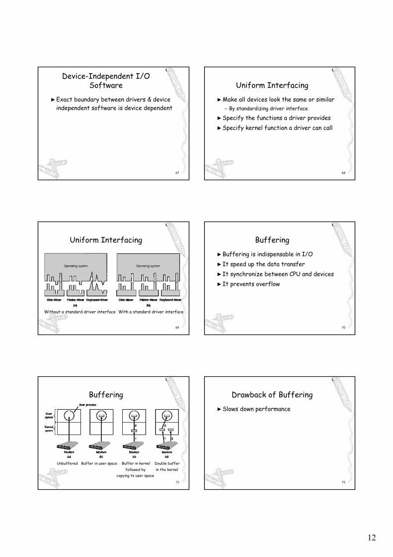
Buffering
Unbuffered Buffer in user space Buffer in kernel Double bufferfollowed by in the kernel
copying to user space72
Drawback of Buffering
►Slows down performance
13
73
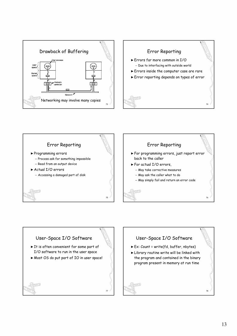
Drawback of Buffering
Networking may involve many copies74
Error Reporting
►Errors far more common in I/O– Due to interfacing with outside world
►Errors inside the computer case are rare►Error reporting depends on types of error
75
Error Reporting
►Programming errors– Process ask for something impossible– Read from an output device
►Actual I/O errors– Accessing a damaged part of disk
76
Error Reporting
►For programming errors, just report error back to the caller
►For actual I/O errors, – May take corrective measures– May ask the caller what to do– May simply fail and return an error code
77
User-Space I/O Software
►It is often convenient for some part of I/O software to run in the user space
►Most OS do put part of IO in user space!
78
User-Space I/O Software
►Ex: Count = write(fd, buffer, nbytes)►Library routine write will be linked with
the program and contained in the binary program present in memory at run time
14
79
User-Space I/O Software
►Other I/O functions in user space include:►Format:
– Scanf and printf
►Spooling– Spooling daemon runs as a user process
80
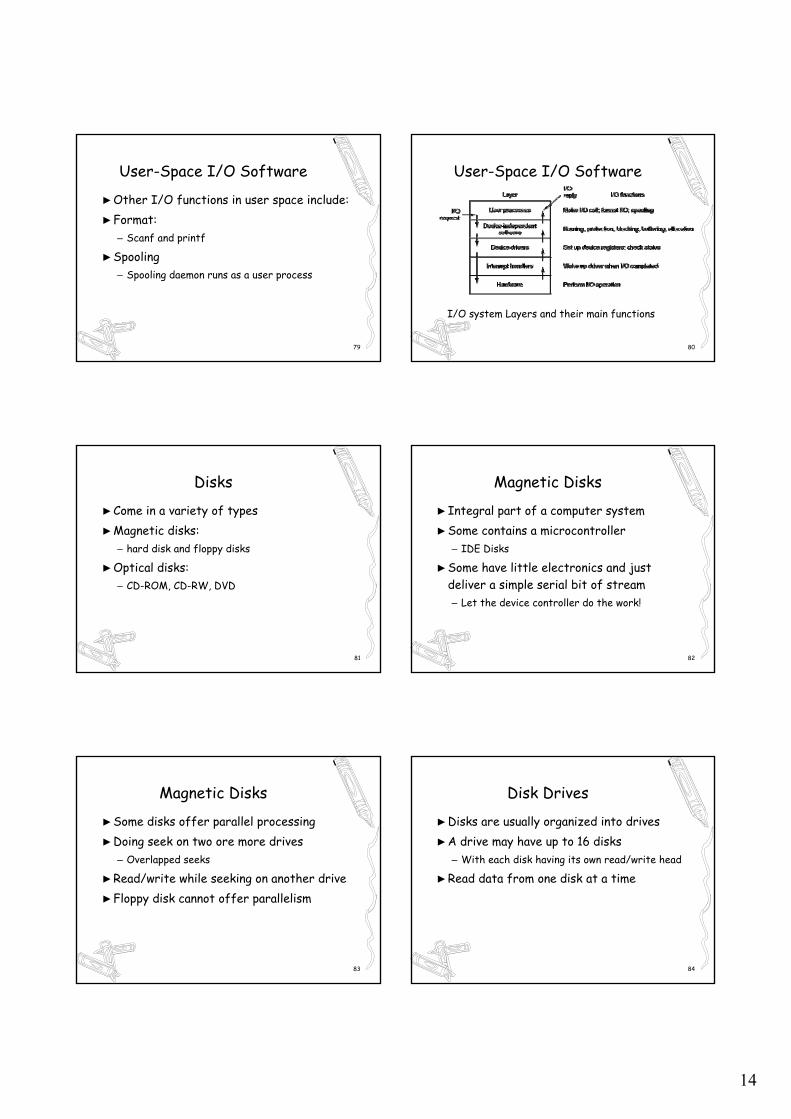
I/O system Layers and their main functions
User-Space I/O Software
81
Disks
►Come in a variety of types►Magnetic disks:
– hard disk and floppy disks
►Optical disks:– CD-ROM, CD-RW, DVD
82
Magnetic Disks
►Integral part of a computer system►Some contains a microcontroller
– IDE Disks
►Some have little electronics and just deliver a simple serial bit of stream– Let the device controller do the work!
83
Magnetic Disks
►Some disks offer parallel processing►Doing seek on two ore more drives
– Overlapped seeks
►Read/write while seeking on another drive►Floppy disk cannot offer parallelism
84
Disk Drives
►Disks are usually organized into drives►A drive may have up to 16 disks
– With each disk having its own read/write head
►Read data from one disk at a time
15
85
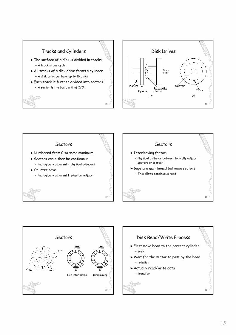
Tracks and Cylinders
►The surface of a disk is divided in tracks– A track is one cycle
►All tracks of a disk drive forms a cylinder– A disk drive can have up to 16 disks
►Each track is further divided into sectors– A sector is the basic unit of I/O
86
Disk Drives
Sector
87
Sectors
►Numbered from 0 to some maximum►Sectors can either be continuous
– i.e. logically adjacent = physical adjacent
►Or interleave– i.e. logically adjacent != physical adjacent
88
Sectors
►Interleaving factor: – Physical distance between logically adjacent
sectors on a track
►Gaps are maintained between sectors– This allows continuous read
89
Sectors
Non-interleaving Interleaving
90
Disk Read/Write Process
►First move head to the correct cylinder– seek
►Wait for the sector to pass by the head– rotation
►Actually read/write data– transfer
16
91
Terms
►Locality of Reference: When record is read from disk, next request is likely to come from near the same place in the file
►Cluster: Smallest unit of file allocation, usually several sectors
92
Terms
►Extent: A group of physically contiguous clusters
►Internal fragmentation: Wasted space within sector if record size does not match sector size; wasted space within cluster if file size is not a multiple of cluster size
93
Seek Time
►Time for I/O head to reach desired track. – Largely determined by distance between I/O
head and desired track
►Track-to-track time: – time to move from track to an adjacent track
►Average Seek time: Average time to reach a track for random access
94
Other Factors
►Rotational Delay or Latency: – Time for data to rotate under I/O head
►One half of a rotation on average►At 7200 rpm, this is 8.3/2 = 4.2ms
95
Transfer time
►Time for data to move under the I/O head►At 7200 rpm: Number of sectors
read/Number of sectors per track * 8.3ms
96
Disk Spec Example
►16.8 GB disk with 10 platters– 1.68GB/platter
►13,085 tracks/platter►256 sectors/track►512 bytes/sector
17
97
Disk Spec Example
►Track-to-track seek time: 2.2 ms►Average seek time: 9.5ms►4KB clusters, 32 clusters/track►Interleaving factor of 3►5400RPM
98
Disk Access Cost Example► Read a 1MB file divided into 2048 records of 512
bytes (1 sector) each► Assume all records are on 8 contiguous tracks► First track: 9.5 + 11.1/2 + 3 x 11.1 = 48.4 ms► Remaining 7 tracks: 2.2 + 11.1/2 + 3 x 11.1 = 41.1
ms► Total: 48.4 + 7 * 41.1 = 335.7ms
99
Disk Access Cost Example► Read a 1MB file divided into 2048 records of 512
bytes (1 sector) each► Assume all file clusters are randomly spread
across the disk► 256 clusters. Cluster read time is (3 x 8)/256 of
a rotation for about 1 ms► 256(9.5 + 11.1/2 + (3 x 8)/256) is about 3877 ms.
or nearly 4 seconds
100
How Much to Read
►Read time for one track:►9.5 + 11.1/2 + 3 x 11.1 = 48.4ms►Read time for one sector►9.5 + 11.1/2 + (1/256)11.1 = 15.1ms
101
How Much to Read
►Read time for one byte :
►9.5 + 11.1/2 = 15.05 ms►Nearly all disk drives read/write one
sector at every I/O access►Also referred to as a page
102
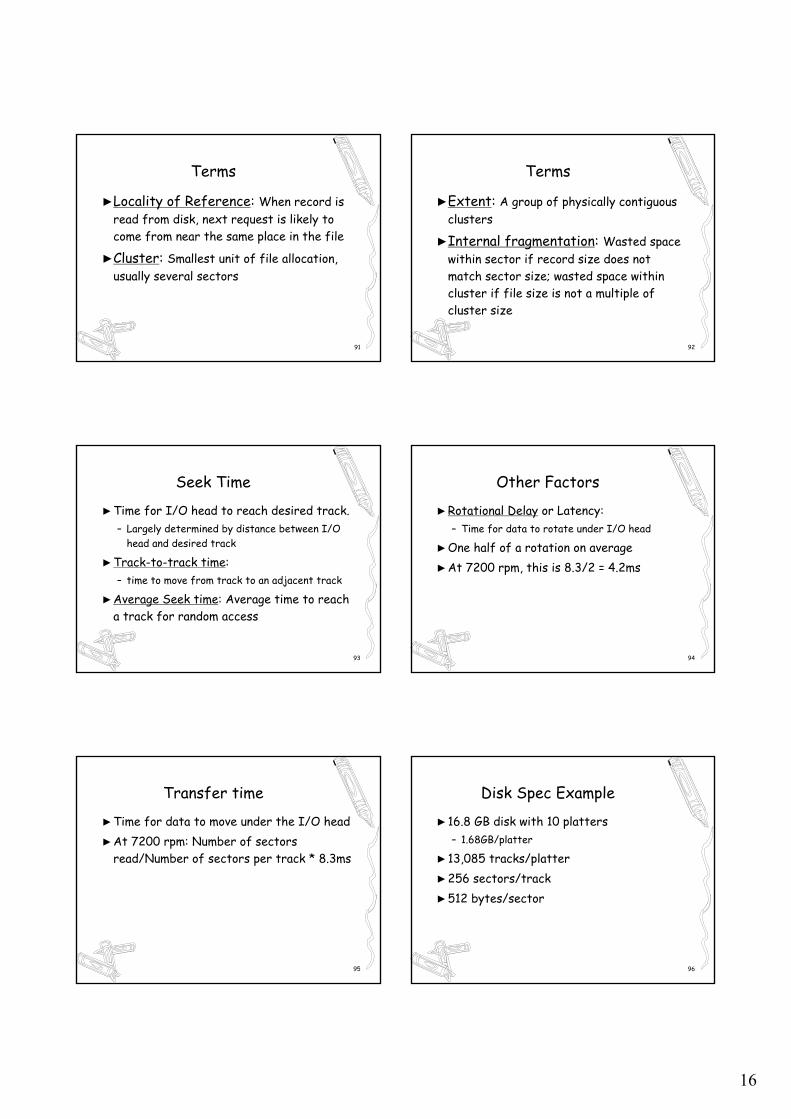
Disk Specification
18
103
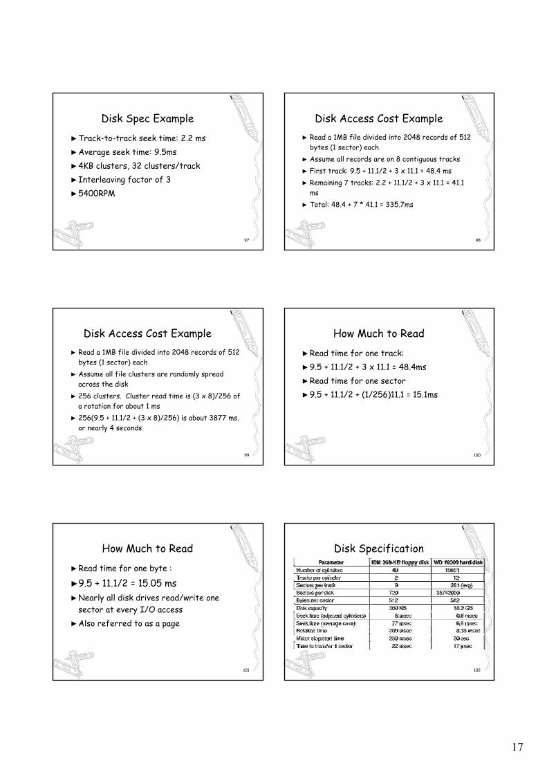
Physical Geometry
►Different tracks have different lengths– Outer tracks are longer than inner tracks– thus tracks may have differing # of sectors
►But this cause difficult to OS– Solution is to provide a virtual geometry
104
Physical Geometry of a Disk
A possible virtual geometry for this disk
105
IBM 75GXP Specification
►Size: 4”×6”×1”, ►Capacity: 76GB►RPM: 7200►Platters: 5►Sectors per track: 370-792►Data rate: 174-374Mbps
106
Virtual Specification
►Number of tracks: 34327►Sectors per track: 512►Average seek time: 9.2ms►Track density: 28350/in
107
RAID
►Redundant Array of Inexpensive Disks►A type of disk organization►Goal: improve performance and reliability►Idea: use multiple disks (drives) as 1 unit►Key technique: stripe
108
RAID
►Depending on how stripe is accomplished►RAID can be classified into 6 levels►RAID 0: stripe in blocks, no redundancy►RAID 1:
– full redundancy, may or may not stripe
►RAID 2: stripe in bits, 1 bit dedicated ECC
19
109
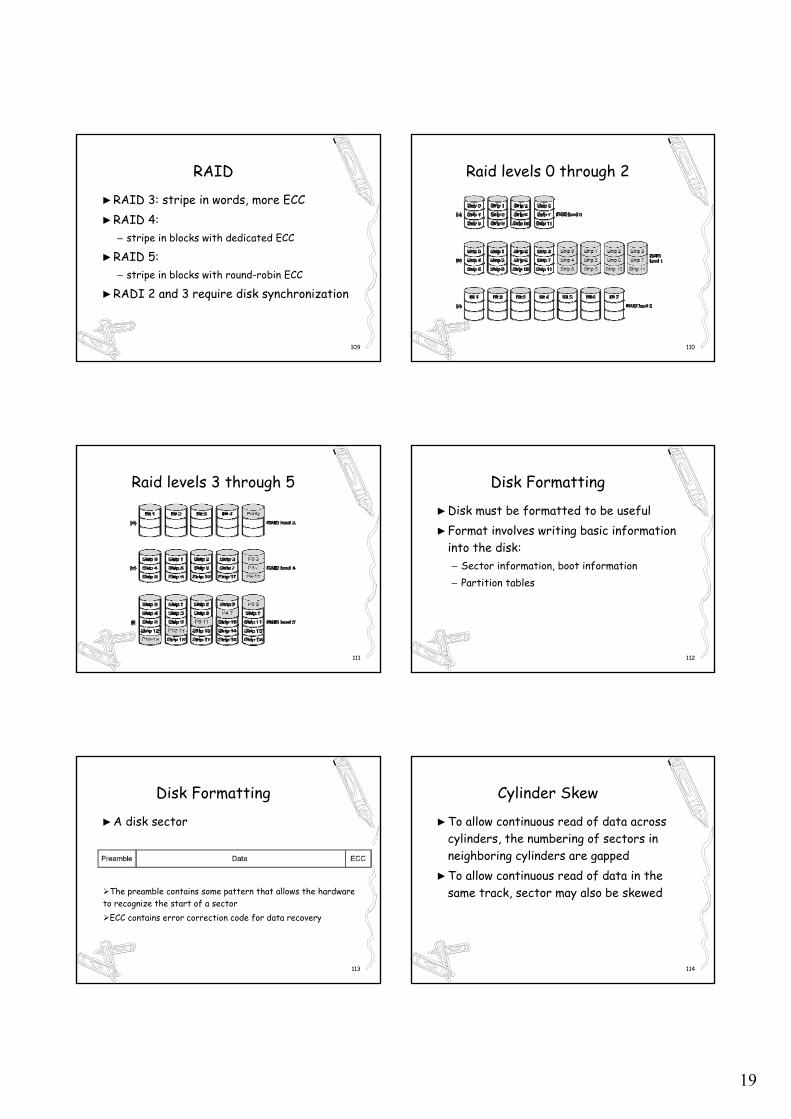
RAID
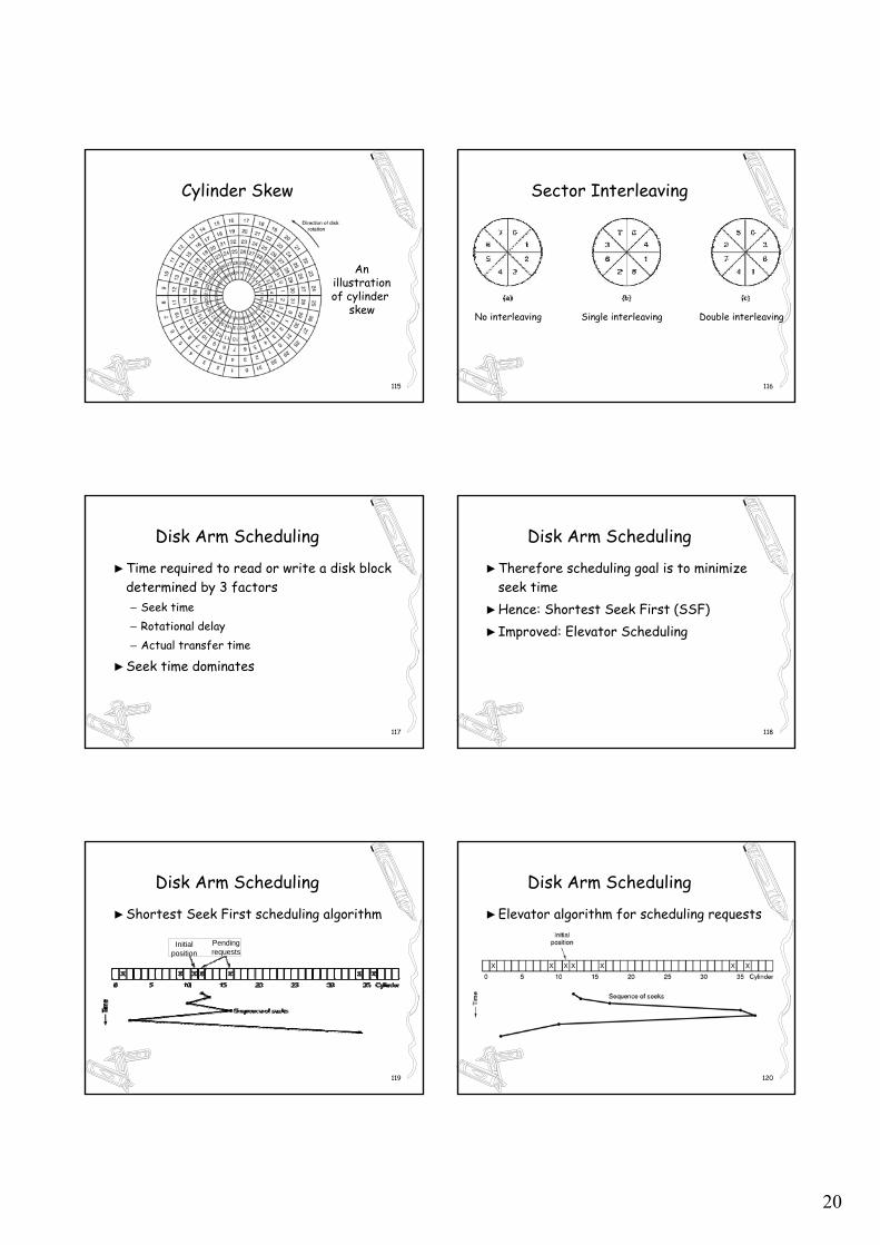
►RAID 3: stripe in words, more ECC►RAID 4:
– stripe in blocks with dedicated ECC
►RAID 5: – stripe in blocks with round-robin ECC
►RADI 2 and 3 require disk synchronization
110
Raid levels 0 through 2
111
Raid levels 3 through 5
112
Disk Formatting
►Disk must be formatted to be useful►Format involves writing basic information
into the disk:– Sector information, boot information– Partition tables
113
Disk Formatting
►A disk sector
The preamble contains some pattern that allows the hardware to recognize the start of a sector
ECC contains error correction code for data recovery
114
Cylinder Skew
►To allow continuous read of data across cylinders, the numbering of sectors in neighboring cylinders are gapped
►To allow continuous read of data in the same track, sector may also be skewed
20
115
Cylinder Skew
Anillustration of cylinder
skew
116
Sector Interleaving
No interleaving Single interleaving Double interleaving
117
Disk Arm Scheduling
►Time required to read or write a disk block determined by 3 factors– Seek time– Rotational delay– Actual transfer time
►Seek time dominates
118
Disk Arm Scheduling
►Therefore scheduling goal is to minimize seek time
►Hence: Shortest Seek First (SSF)►Improved: Elevator Scheduling
119
Disk Arm Scheduling
►Shortest Seek First scheduling algorithm
Initialposition
Pendingrequests
120
Disk Arm Scheduling
►Elevator algorithm for scheduling requests
21
121
Error Handling►Disk defect is inevitable
– Defect in uniform substrate – Defect in fine oxide coating
►Motion defect increase as time goes by– Read/write head moves into the wrong place
►Environment pollution– Dust and speck cause temporary RW errors
122
Error Handling
►Disk defect cause bad blocks►If the defect is small, let the ECC correct►Otherwise, let entire sector go bad and
deal with bad sector in controller or OS
123
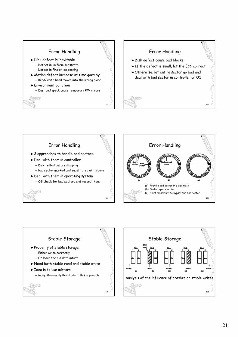
Error Handling
►2 approaches to handle bad sectors:►Deal with them in controller
– Disk tested before shipping – bad sector marked and substituted with spare
►Deal with them in operating system– OS check for bad sectors and record them
124
Error Handling
(a) Found a bad sector in a disk track (b) Find a replace sector(c) Shift all sectors to bypass the bad sector
125
Stable Storage
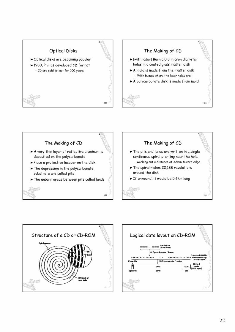
►Property of stable storage:– Either write correctly – Or leave the old data intact
►Need both stable read and stable write►Idea is to use mirrors
– Many storage systems adapt this approach
126
Stable Storage
Analysis of the influence of crashes on stable writes
22
127
Optical Disks
►Optical disks are becoming popular►1980, Philips developed CD format
– CD are said to last for 100 years
128
The Making of CD
► (with laser) Burn a 0.8 micron diameter holes in a coated glass master disk
►A mold is made from the master disk– With bumps where the laser holes are
►A polycarbonate disk is made from mold
129
The Making of CD
►A very thin layer of reflective aluminum is deposited on the polycarbonate
►Place a protective lacquer on the disk►The depression in the polycarbonate
substrate are called pits►The unburn areas between pits called lands
130
The Making of CD
►The pits and lands are written in a single continuous spiral starting near the hole – working out a distance of 32mm toward edge
►The spiral makes 22,188 revolutions around the disk
►If unwound, it would be 5.6km long
131
Structure of a CD or CD-ROM
132
Logical data layout on CD-ROM
23
133
CD-ROM
►1984, Philips & Sony developed the CD-ROM standard for storing computer data
►1986, graphics and multimedia is added►High Sierra file standard developed
– It becomes IS 9660
134
CD-Recordable
►Nick name CD-R►Can be used to recording data once
135
Making of CD-R
►Starts with polycarbonate blanks►But they contains a 0.6mm groove
– To guide the laser for writing
►The groove has a sinusoidal excursion of 0.3mm at a frequency of exactly 22.05kHz– To provide continuous feedback so that
rotation speed can be accurately monitored
136
Making of CD-R
►CD-Rs look like regular CD-ROMs►But they are gold coated instead of
aluminum for the reflective layer►Two kinds of dyes are used:
– Cyanine, which is green– Pthalocyanine, which is a yellowish orange
137
Making of CD-R
►Initially, the dye are transparent and lets laser lights pass through and reflect off the gold layers
►To write, laser is turned into high power (8-16mW), and hits a spot of dye
►The dye heats up and break chemical bond
138
Making of CD-R
►This creates a dark spot►When read back (at 0.5mW), the
photodetector sees a difference between the dark spots and the transparent areas
►This is interpreted as pits and lands
24
139
CD-R
140
CD-R
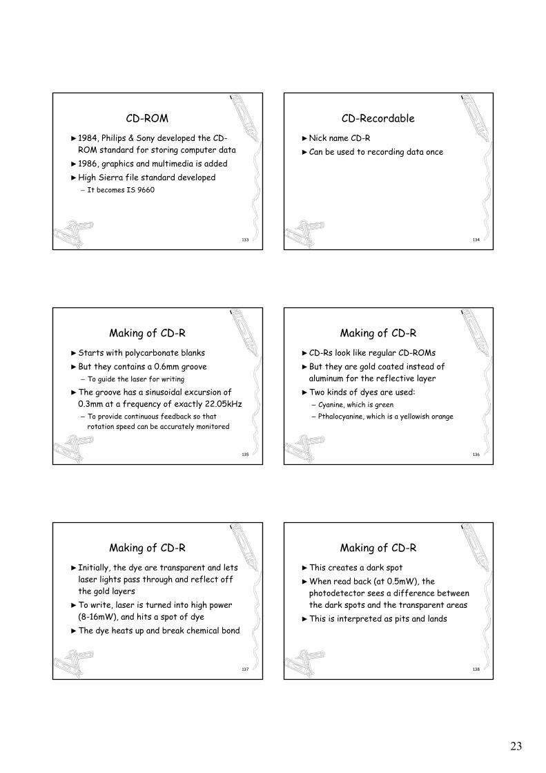
►Cross section of a CD-R disk and laser– not to scale
►Silver CD-ROM has similar structure– without dye layer– with pitted aluminum layer instead of gold
141
CD-Rewritable
►Same as CD-R, except it uses►Alloy of silver, indium, antimony, and
tellurium for the recording layer►Instead of cyanine or ptholcyanine
142
CD-Rewritable
►CD-RW drive use laser of 3 differing power►High power for recording►Lower power for read back►Middle power for reforming its state
– To become a land again
143
DVD
►Digital Video (Versatile) Disk►Developed by cooperating industries:
– Movie, consumer electronics, computer
►DVD uses same general design as CDs►But with the following differences:
144
DVD
►Smaller pits (0.4 micron vs. 0.8 micron)►Tighter spiral
– 0.74 micron between tracks– vs. 1.6 microns for CDs
►Red laser (at 0.65 micro vs. 0.78 microns)
25
145
DVD
►Together, the changes raise the capacity sevenfold to 4.7GB
►But the switch to red laser means that DVD player will need a second laser or fancy conversion to read existing CDs
146
DVD
►There are four DVD formats:►Single-sided, single-layer (4.7GB)►Single-sided, double-layer (8.5GB)►Double-sided, single-layer (9.4GB)►Double-sided, dual-layer (17GB)
147
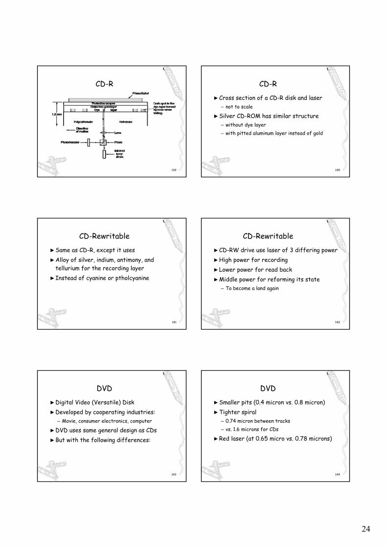
A double sided, dual layer DVD disk
DVD
148
Clocks
►Also called Timers►Essential for OS to work properly►Synchronizing various circuits in computer►Regulates the OS interrupts
– Prevents one process from monopolizing CPU
►Keeps time of day (real-time)
149
Clock Hardware
►Two types of clocks are commonly used►Power-line clocks
– Cause interrupts on every voltage cycle– At either 50Hz (220V) or 60Hz (110V)– Used to dominate, now very rare
►Crystal Oscillator Clocks– Now commonly used in computers
150
Crystal Oscillator Clocks
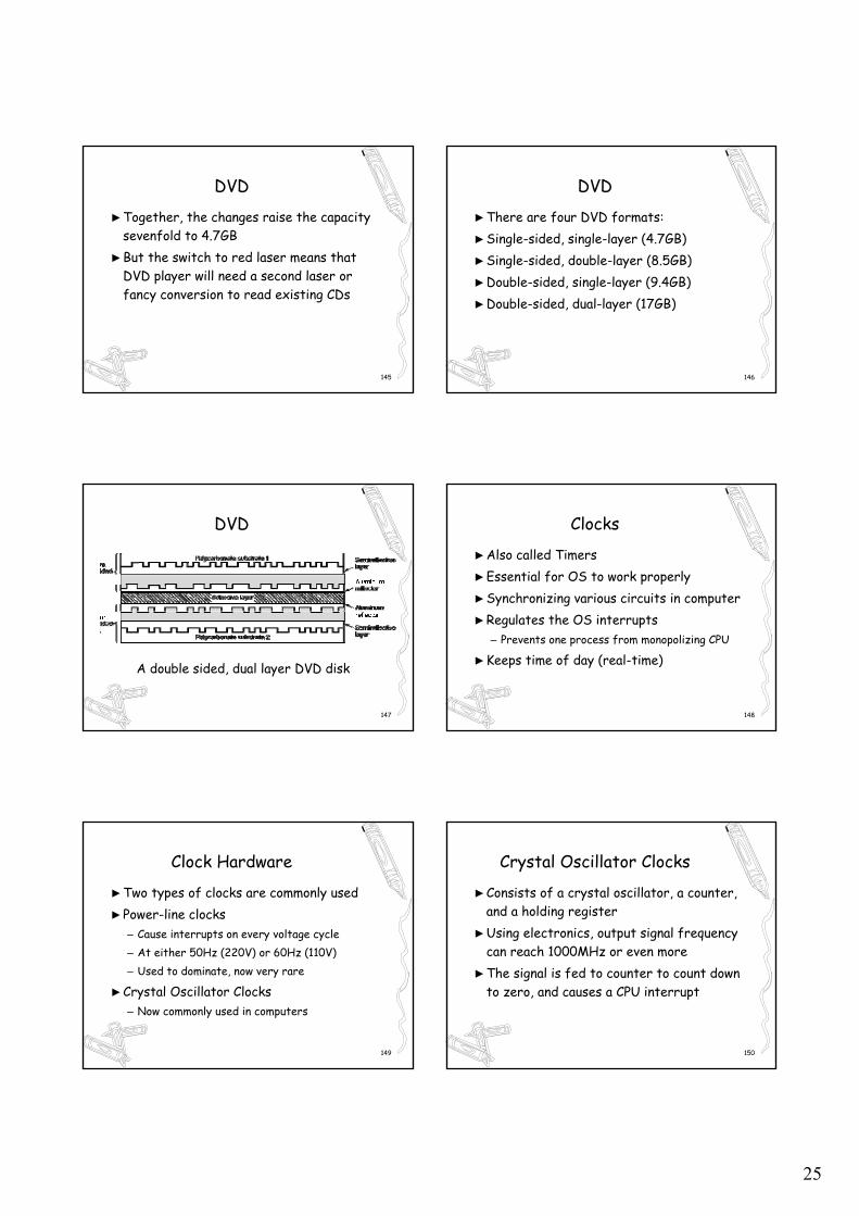
►Consists of a crystal oscillator, a counter, and a holding register
►Using electronics, output signal frequency can reach 1000MHz or even more
►The signal is fed to counter to count down to zero, and causes a CPU interrupt
26
151
Crystal Oscillator Clocks
A programmable clock
152
Clock Software
►Clock hardware only generates interrupts at known intervals
►Everything else involved is done by software►Also called the clock driver
153
Tasks of Clock Drivers►Maintaining time of day
– Explain shortly
►Preventing process from running longer than they are allowed to– by recording clock ticks a process has run– Call scheduler when quantum exhausts
►Accounting for CPU usage
154
Tasks of Clock Drivers
►Handling the ALARM system call by users►Providing watchdog timers
– Do something after a timer expires– i.e. floppy disk needs to get to speed before read
►Profiling, monitoring, and data gathering– Providing statistical information about system
155
Time of Day
►Just requires to incrementing a counter at each clock ticks
►Need to watch the length of the counter►A 32 bit counter will overflow in 2 years
with clock rate of 60Hz►3 approaches proposed to solve the problem
156
Time of Day
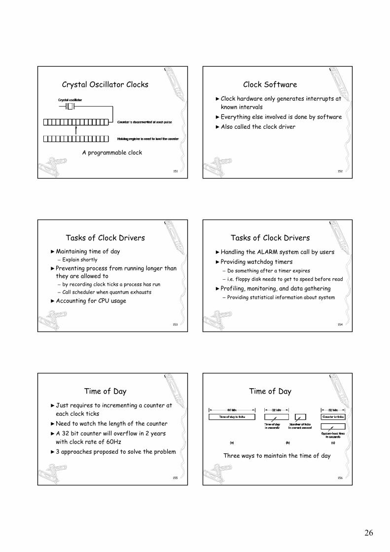
Three ways to maintain the time of day
27
157
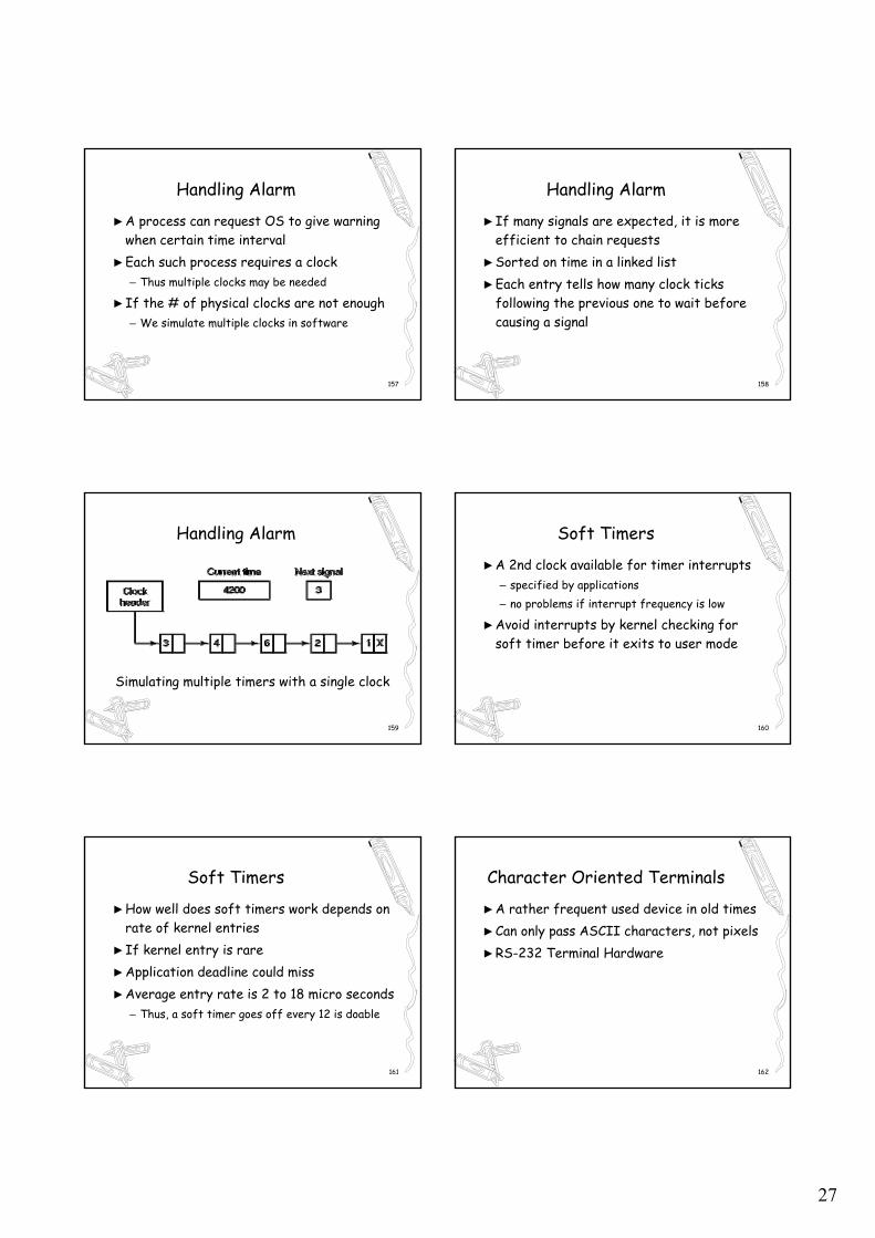
Handling Alarm
►A process can request OS to give warning when certain time interval
►Each such process requires a clock– Thus multiple clocks may be needed
►If the # of physical clocks are not enough– We simulate multiple clocks in software
158
Handling Alarm
►If many signals are expected, it is more efficient to chain requests
►Sorted on time in a linked list►Each entry tells how many clock ticks
following the previous one to wait before causing a signal
159
Handling Alarm
Simulating multiple timers with a single clock
160
Soft Timers
►A 2nd clock available for timer interrupts– specified by applications– no problems if interrupt frequency is low
►Avoid interrupts by kernel checking for soft timer before it exits to user mode
161
Soft Timers
►How well does soft timers work depends on rate of kernel entries
►If kernel entry is rare►Application deadline could miss►Average entry rate is 2 to 18 micro seconds
– Thus, a soft timer goes off every 12 is doable
162
Character Oriented Terminals
►A rather frequent used device in old times►Can only pass ASCII characters, not pixels►RS-232 Terminal Hardware
28
163
RS-232 Terminal Hardware
164
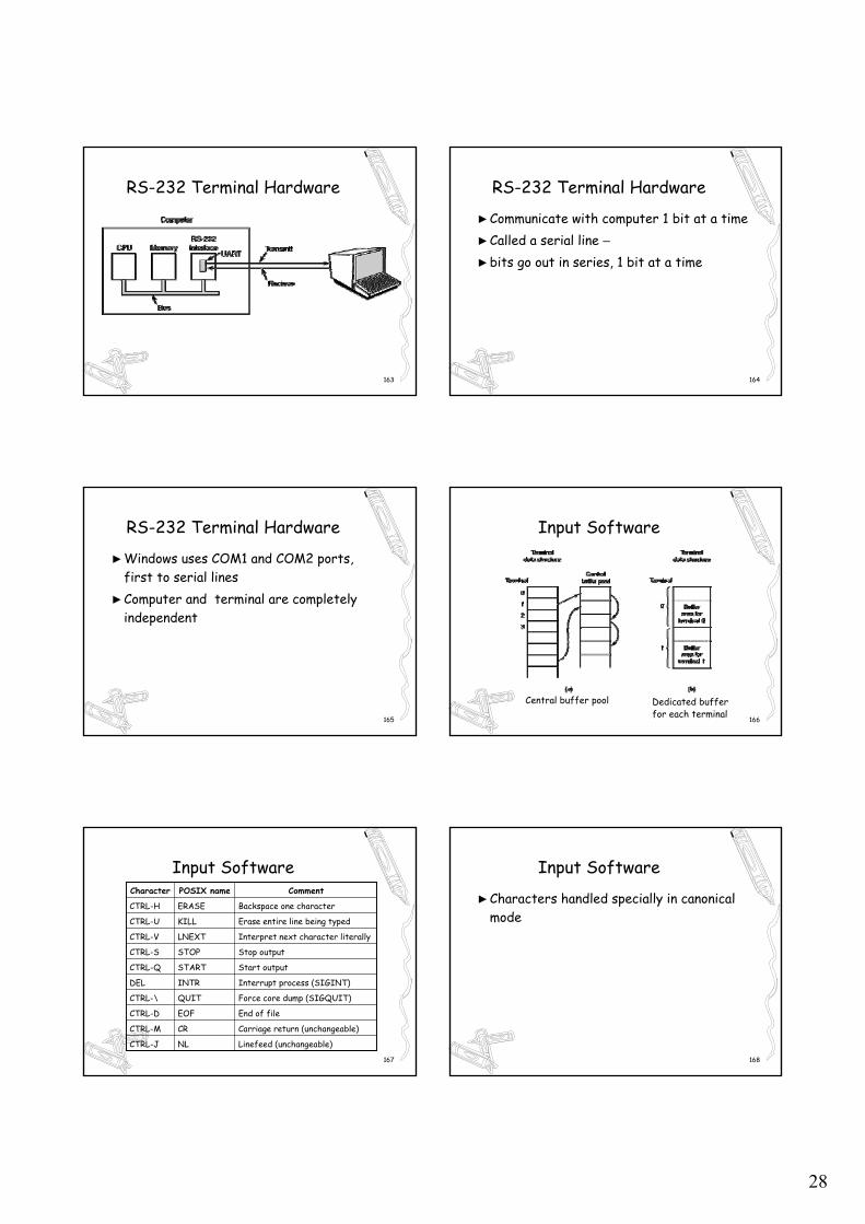
RS-232 Terminal Hardware
►Communicate with computer 1 bit at a time►Called a serial line –►bits go out in series, 1 bit at a time
165
RS-232 Terminal Hardware
►Windows uses COM1 and COM2 ports, first to serial lines
►Computer and terminal are completely independent
166
Central buffer pool
Input Software
Dedicated buffer for each terminal
167
Input Software
Linefeed (unchangeable)NLCTRL-J
Carriage return (unchangeable)CRCTRL-M
End of fileEOFCTRL-D
Force core dump (SIGQUIT)QUITCTRL-\
Interrupt process (SIGINT)INTRDEL
Start outputSTARTCTRL-Q
Stop outputSTOPCTRL-S
Interpret next character literallyLNEXTCTRL-V
Erase entire line being typedKILLCTRL-U
Backspace one characterERASECTRL-H
CommentPOSIX nameCharacter
168
Input Software
►Characters handled specially in canonical mode
29
169
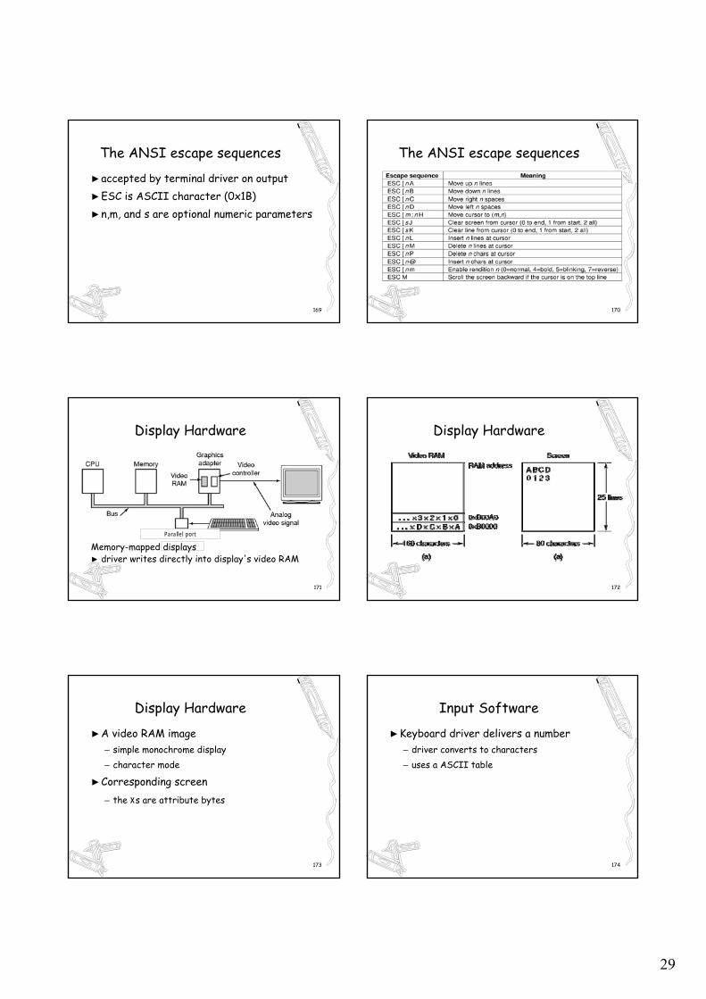
►accepted by terminal driver on output►ESC is ASCII character (0x1B)►n,m, and s are optional numeric parameters
The ANSI escape sequences
170
The ANSI escape sequences
171
Parallel port
Display Hardware
Memory-mapped displays► driver writes directly into display's video RAM
172
Display Hardware
173
Display Hardware
►A video RAM image – simple monochrome display– character mode
►Corresponding screen– the xs are attribute bytes
174
Input Software
►Keyboard driver delivers a number– driver converts to characters– uses a ASCII table
30
175
Input Software
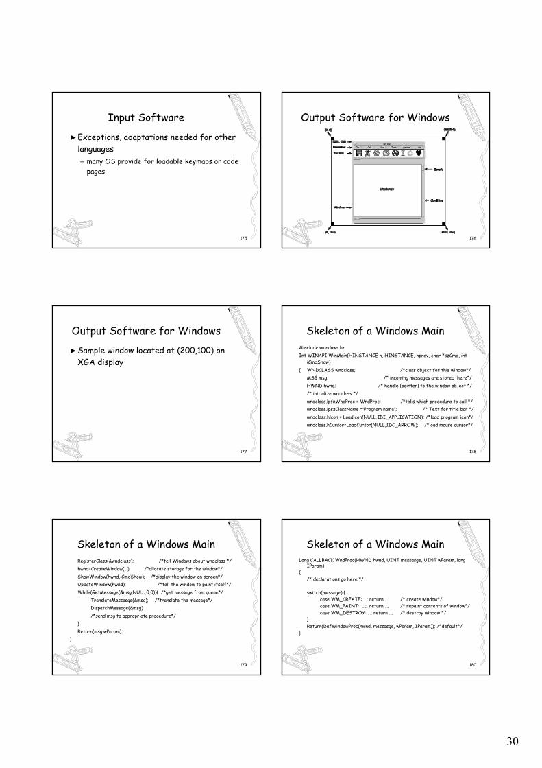
►Exceptions, adaptations needed for other languages– many OS provide for loadable keymaps or code
pages
176
Output Software for Windows
177
Output Software for Windows
►Sample window located at (200,100) on XGA display
178
Skeleton of a Windows Main#include <windows.h>Int WINAPI WinMain(HINSTANCE h, HINSTANCE, hprev, char *szCmd, int
iCmdShow){ WNDCLASS wndclass; /*class object for this window*/
MSG msg; /* incoming messages are stored here*/HWND hwnd; /* handle (pointer) to the window object *//* initialize wndclass */wndclass.lpfnWndProc = WndProc; /*tells which procedure to call */wndclass.lpszClassName =“Program name”; /* Text for title bar */wndclass.hlcon = Loadlcon(NULL,IDI_APPLICATION); /*load program icon*/wndclass.hCursor=LoadCursor(NULL,IDC_ARROW); /*load mouse cursor*/
179
Skeleton of a Windows MainRegisterClass(&wndclass); /*tell Windows about wndclass */hwnd=CreateWindow(…); /*allocate storage for the window*/ShowWindow(hwnd,iCmdShow); /*display the window on screen*/UpdateWindow(hwnd); /*tell the window to paint itself*/While(GetMessage(&msg,NULL,0,0)){ /*get message from queue*/
TranslateMessasge(&msg); /*translate the message*/DispatchMessage(&msg) /*send msg to appropriate procedure*/
}Return(msg.wParam);
}
180
Skeleton of a Windows MainLong CALLBACK WndProc(HWND hwnd, UINT messasge, UINT wParam, long
IParam){
/* declarations go here */
switch(message) {case WM_CREATE: …; return …; /* create window*/case WM_PAINT: …; return …; /* repaint contents of window*/case WM_DESTROY: …; return …; /* destroy window */
}Return(DefWindowProc(hwnd, messasge, wParam, IParam)); /*default*/
}
31
181
Output Software for Windows
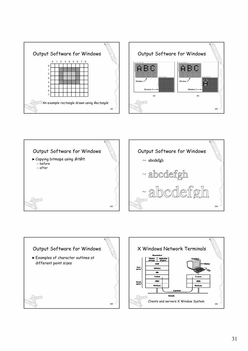
An example rectangle drawn using Rectangle182
Output Software for Windows
183
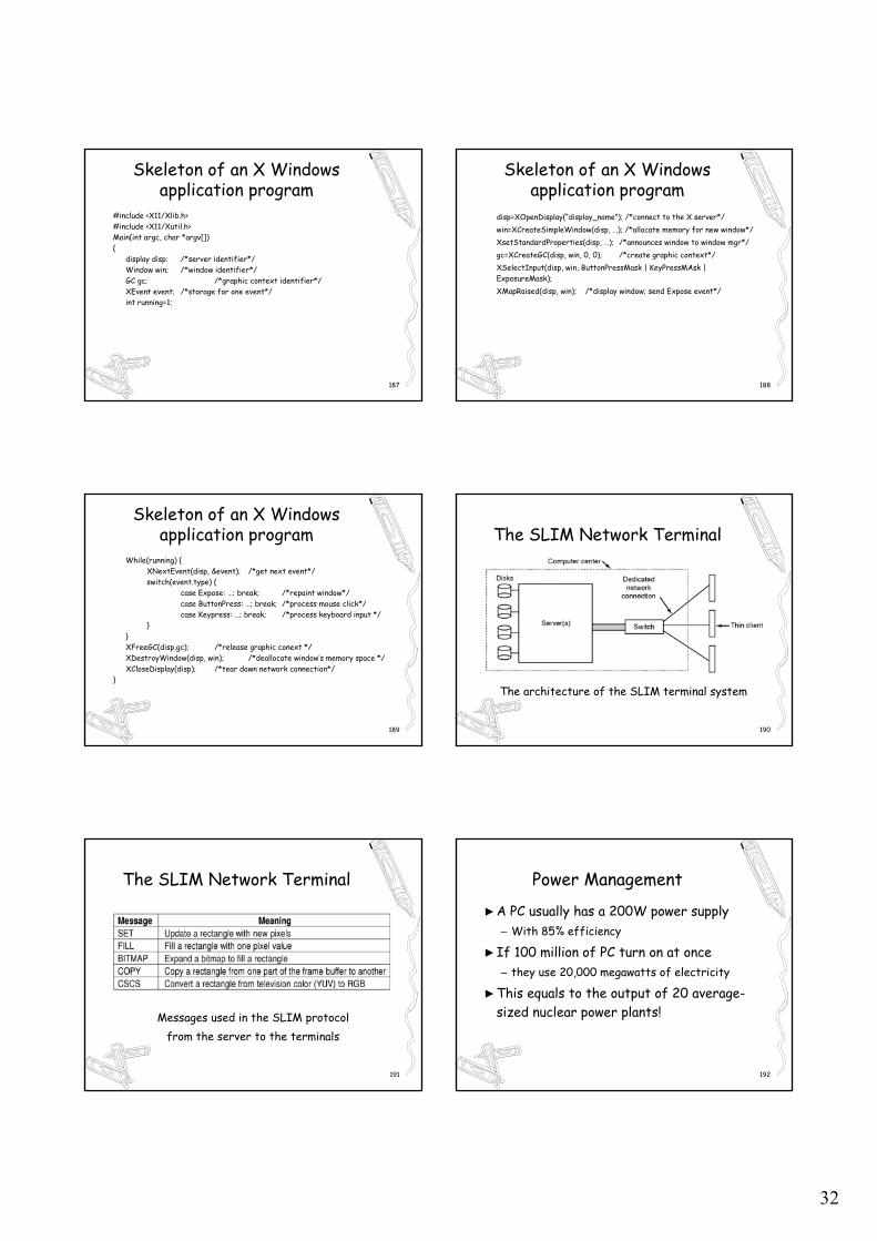
Output Software for Windows►Copying bitmaps using BitBlt.
– before– after
184
Output Software for Windows
185
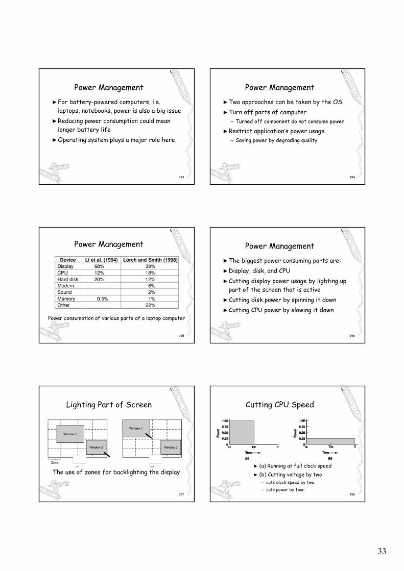
Output Software for Windows
►Examples of character outlines at different point sizes
186
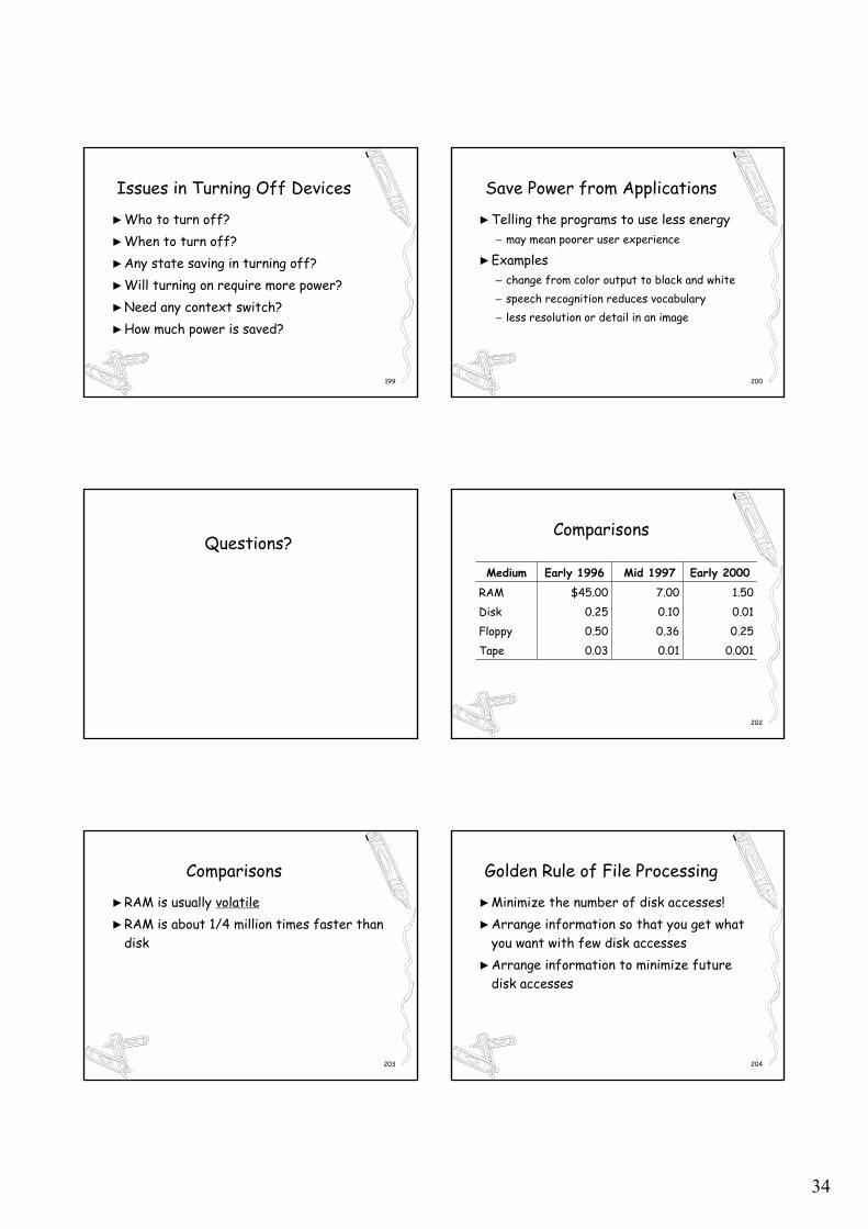
X Windows Network Terminals
Clients and servers X Window System
32
187
Skeleton of an X Windows application program
#include <X11/Xlib.h>#include <X11/Xutil.h>Main(int argc, char *argv[]){
display disp; /*server identifier*/Window win; /*window identifier*/GC gc; /*graphic context identifier*/XEvent event; /*storage for one event*/int running=1;
188
Skeleton of an X Windows application program
disp=XOpenDisplay(“display_name”); /*connect to the X server*/win=XCreateSimpleWindow(disp, …); /*allocate memory for new window*/XsetStandardProperties(disp, …); /*announces window to window mgr*/gc=XCreateGC(disp, win, 0, 0); /*create graphic context*/XSelectInput(disp, win, ButtonPressMask | KeyPressMAsk | ExposureMask);XMapRaised(disp, win); /*display window; send Expose event*/
189
Skeleton of an X Windows application program
While(running) {XNextEvent(disp, &event); /*get next event*/switch(event.type) {
case Expose: …; break; /*repaint window*/case ButtonPress: …; break; /*process mouse click*/case Keypress: …; break; /*process keyboard input */
}}XFreeGC(disp,gc); /*release graphic conext */XDestroyWindow(disp, win); /*deallocate window’s memory space */XCloseDisplay(disp); /*tear down network connection*/
}
190
The SLIM Network Terminal
The architecture of the SLIM terminal system
191
The SLIM Network Terminal
Messages used in the SLIM protocolfrom the server to the terminals
192
Power Management
►A PC usually has a 200W power supply– With 85% efficiency
►If 100 million of PC turn on at once– they use 20,000 megawatts of electricity
►This equals to the output of 20 average-sized nuclear power plants!
33
193
Power Management
►For battery-powered computers, i.e. laptops, notebooks, power is also a big issue
►Reducing power consumption could mean longer battery life
►Operating system plays a major role here
194
Power Management
►Two approaches can be taken by the OS:►Turn off parts of computer
– Turned off component do not consume power
►Restrict application’s power usage– Saving power by degrading quality
195
Power Management
Power consumption of various parts of a laptop computer
196
Power Management
►The biggest power consuming parts are:►Display, disk, and CPU►Cutting display power usage by lighting up
part of the screen that is active►Cutting disk power by spinning it down►Cutting CPU power by slowing it down
197
Lighting Part of Screen
The use of zones for backlighting the display
198
Cutting CPU Speed
► (a) Running at full clock speed► (b) Cutting voltage by two
– cuts clock speed by two, – cuts power by four
34
199
Issues in Turning Off Devices
►Who to turn off?►When to turn off?►Any state saving in turning off?►Will turning on require more power?►Need any context switch?►How much power is saved?
200
Save Power from Applications
►Telling the programs to use less energy– may mean poorer user experience
►Examples– change from color output to black and white– speech recognition reduces vocabulary– less resolution or detail in an image
Questions?
202
Comparisons
0.0010.010.03Tape0.250.360.50Floppy0.010.100.25Disk1.507.00$45.00RAM
Early 2000Mid 1997Early 1996Medium
203
Comparisons
►RAM is usually volatile►RAM is about 1/4 million times faster than
disk
204
Golden Rule of File Processing
►Minimize the number of disk accesses!►Arrange information so that you get what
you want with few disk accesses►Arrange information to minimize future
disk accesses
35
205
Golden Rule of File Processing
►An organization for data on disk is often called a file structure
►Disk-based space/time tradeoff: Compress information to save processing time by reducing disk accesses
206
Device Independence
►Problem: – lots of different brands of disks, disk
interfaces, – And disk controllers– each with their own custom control interface
►Same is true of any I/O device– network card, video card, keyboard, mouse, etc.
207
Device Independence
►Add a “device driver” layer– to hide this diversity/complexity
►An abstraction makes things “better”– for things that use the abstraction
208
Device Independence
Millions of hardware devices
Rest of operating systems
Device drivers
Physical interface
Virtual interface
209
Example Abstractions
►Threads: – user doesn’t have to worry about sharing CPU
►Addresses spaces: – user doesn’t have to worry about sharing
physical memory– or physical memory size
210
Example Abstractions
►TCP: – user doesn’t have to worry about the unreliable
network
►Device drivers: – frees the user (the rest of the OS) from
worrying about differences in devices – e.g. the device registers used to control the
device
36
211
Byte Oriented Block Oriented
►Disks are accessed in terms of blocks (sectors)– e.g. 512 bytes
►But programs deal in bytes►Questions
– How to read less than a block– How to write less than a block
212
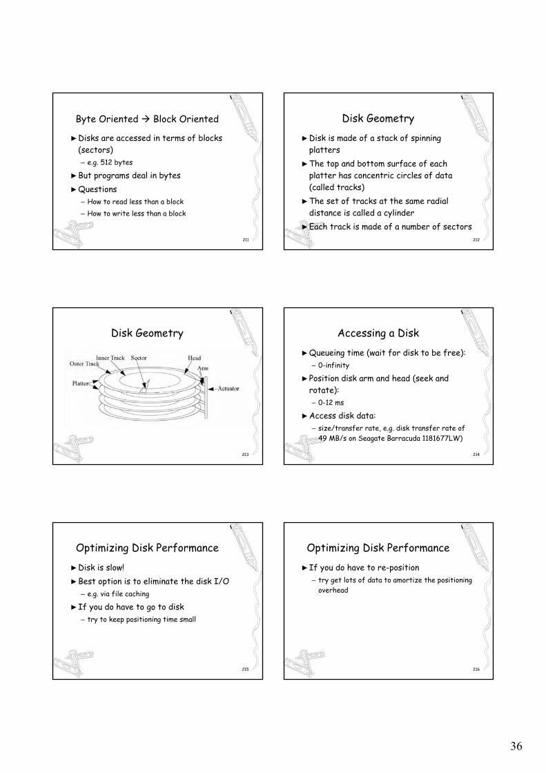
Disk Geometry
►Disk is made of a stack of spinning platters
►The top and bottom surface of each platter has concentric circles of data (called tracks)
►The set of tracks at the same radial distance is called a cylinder
►Each track is made of a number of sectors
213
Disk Geometry
214
Accessing a Disk
►Queueing time (wait for disk to be free): – 0-infinity
►Position disk arm and head (seek and rotate): – 0-12 ms
►Access disk data: – size/transfer rate, e.g. disk transfer rate of
49 MB/s on Seagate Barracuda 1181677LW)
215
Optimizing Disk Performance
►Disk is slow!►Best option is to eliminate the disk I/O
– e.g. via file caching
►If you do have to go to disk– try to keep positioning time small
216
Optimizing Disk Performance
►If you do have to re-position– try get lots of data to amortize the positioning
overhead
37
217
Optimizing Disk Performance
►efficiency = – transfer time / (positioning time + transfer
time)
►e.g. on Seagate Barracuda 1181677LW, – transferring 300 KB takes 6 ms (50%
efficiency)
218
Reducing Positioning Time
►Optimize when writing data to disk►Place items that will be accessed together
near each other on disk– How to know in advance that two items will be
accessed together?
219
Reducing Positioning Time
►Optimize when reading data from disk– minimize positioning time at time of access– rather than at time of creation
220
Disk Scheduling
►Re-order a set of disk accesses to decrease the total positioning time– can be implemented in the OS– or in the disk hardware
221
Disk Scheduling
►FCFS (first come, first served)►SSTF (shortest seek time first)►SCAN►LOOK►C-SCAN
222
FCFS
►e.g. (start at track 53): – 98, 183, 37, 122, 14, 124, 65, 67
►total head movement: – 640 tracks (average 80 per seek)
38
223
SSTF
►e.g. 53->65->67->37->14->98->122->124->183
►total head movement: – 236 tracks (average 30 per seek)
►Any problems with SSTF?
224
SCAN
►Sweep the disk from one end to the other►Then back again►Sometimes called “Elevator algorithms”
225
LOOK
►A variant of SCAN►when sweeping toward the end
– stop if there are no requests beyond the current point
– e.g. 53->37->14->65->67->98->122->124->183
►total head movement: – 208 tracks (average 26 per seek)
226
C-SCAN
►Always sweep the disk from beginning to end
►Then seek all the way back to the beginning
►And repeat
227
Disk Scheduling
►Disk scheduling only improves positioning time with multiple outstanding requests– otherwise service the sole request