Embed Size (px)
Citation preview
Containment Internal Structure: Design Criteria for SC Walls MUAP-11019 (R1)
Mitsubishi Heavy Industries, LTD.
CONTAINMENT INTERNAL STRUCTURE: DESIGN CRITERIA FOR SC WALLS
MUAP-11019
Non-proprietary Version
January 2013
© 2013 Mitsubishi Heavy Industries, Ltd.
All Rights Reserved
Containment Internal Structure: Design Criteria for SC Walls MUAP-11019 (R1)
Mitsubishi Heavy Industries, LTD.
Revision History
Revision Page Description
A
All
Initial Issue for Review
0 All Initial Issue
1 All
Incorporation of RAI responses, RAI 905-6311 and RAI 931-6467. Editorial changes were made throughout. The following sections were substantially revised or added as new sections: 1.0, 1.1, 1.2, 2.3, 2.5, 2.6, 2.7, 2.8, 2.9, 2.10, 4.3, 5.2, 5.4, 6.2, 6.4, 8.0, 8.1, 8.2, 8.3, 8.4, 8.5, 8.6, 8.7, 9.1, and 10.0. In addition, the Appendices were substantially revised, as follows:
The Revision 0 Appendix 1 relating to the previous deformed wire tie bar detail was removed.
The Revision 0 Appendix 2 became Appendix 1, and the sample calculations in this Appendix were revised for consistency with Chapter 8 revisions.
The Revision 0 Appendix 3 containing discussion of confirmatory testing was removed; this information is now summarized in TeR MUAP-11013 Rev. 2.
The Revision 0 Appendix 4 containing the Primary Shielding design criteria became Appendix 2.
The previous Appendices 5, 6, and 7 that contained SC testing research reports were removed. The SC testing research reports are now provided in Appendix E of TeR MUAP-11005 Rev. 1.
Containment Internal Structure: Design Criteria for SC Walls MUAP-11019 (R1)
Mitsubishi Heavy Industries, LTD.
© 2013
MITSUBISHI HEAVY INDUSTRIES, LTD.
All Rights Reserved
This document has been prepared by Mitsubishi Heavy Industries, Ltd. (MHI) in connection with the United States Nuclear Regulatory Commission’s (NRC) licensing review of MHI’s US-APWR nuclear power plant design. No right to disclose, use or copy any of the information in this document, other that by the NRC and its contractors in support of the licensing review of the US-APWR, is authorized without the express written permission of MHI.
This document contains technology information and intellectual property relating to the US-APWR and it is delivered to the NRC on the express condition that it not be disclosed, copied or reproduced in whole or in part, or used for the benefit of anyone other than MHI without the express written permission of MHI, except as set forth in the previous paragraph.
This document is protected by the laws of Japan, U.S. copyright law, international treaties and conventions, and the applicable laws of any country where it is being used.
Mitsubishi Heavy Industries, Ltd. 16-5, Konan 2-chome, Minato-ku
Tokyo 108-8215 Japan
Containment Internal Structure: Design Criteria for SC Walls MUAP-11019 (R1)
Mitsubishi Heavy Industries, LTD. i
TABLE OF CONTENTS
LIST OF ACRONYMS ...................................................................................................................iii LIST OF FIGURES ...................................................................................................................... iv LIST OF TABLES .......................................................................................................................... v ABSTRACT .................................................................................................................................. vi DESIGN PHILOSOPHY AND EXECUTIVE SUMMARY............................................................. vii
1.0 SC WALLS IN US-APWR CIS ....................................................................................... 1-1 1.1 SC Wall Dimensions .............................................................................................. 1-1 1.2 General Design Approach and MUAP-11019 Purpose ......................................... 1-3 1.3 Report Outline ....................................................................................................... 1-4
2.0 SC SPECIFIC DESIGN ISSUES AND SECTION DETAILING ..................................... 2-1 2.1 Section Details ...................................................................................................... 2-1 2.2 Local Buckling of Steel Faceplates ....................................................................... 2-1 2.3 Shear Connector Strength and Spacing ................................................................ 2-5 2.4 Steel Faceplate Development Length ................................................................... 2-7 2.5 Interfacial Shear Strength ...................................................................................... 2-9 2.6 Tie Bar Spacing and Size .................................................................................... 2-12 2.7 Delamination or Splitting Failure ......................................................................... 2-14 2.8 Tie Bar Detailing .................................................................................................. 2-19 2.9 SC Faceplate Penetration Detailing .................................................................... 2-20 2.10 Design for Commodity Support Loads ................................................................ 2-21
3.0 AXIAL TENSION STRENGTH ....................................................................................... 3-1 3.1 ACI 349-06 Code Recommendation ..................................................................... 3-1 3.2 Applicability to SC Design ..................................................................................... 3-1
4.0 AXIAL COMPRESSIVE STRENGTH ............................................................................ 4-1 4.1 ACI 349-06 Code Recommendation ..................................................................... 4-1 4.2 Applicability to SC Design ..................................................................................... 4-1 4.3 Additional Considerations for SC Compressive Strength ...................................... 4-2
5.0 OUT-OF-PLANE FLEXURAL STRENGTH ................................................................... 5-1 5.1 ACI 349-06 Code Recommendations .................................................................... 5-1 5.2 Applicability to SC Design ..................................................................................... 5-2 5.3 Definition of SC Wall Uniaxial Moment Capacity ................................................... 5-3 5.4 Experimental Verification of SC Flexural Capacity ................................................ 5-5
6.0 OUT-OF-PLANE SHEAR STRENGTH .......................................................................... 6-1 6.1 ACI 349-06 Code Recommendations .................................................................... 6-1 6.2 Recommendation for SC Walls ............................................................................. 6-2 6.3 Verification Using Experimental Data .................................................................... 6-3 6.4 Shear Strength Contribution (Vs) of Tie Bars......................................................... 6-4
7.0 IN-PLANE SHEAR STRENGTH .................................................................................... 7-1 7.1 ACI 349-06 Code Recommendations .................................................................... 7-1 7.2 Experimental Data for In-Plane Shear Strength of SC Walls ................................ 7-2 7.3 Conservative Equation for In-plane Shear Strength .............................................. 7-4
Containment Internal Structure: Design Criteria for SC Walls MUAP-11019 (R1)
Mitsubishi Heavy Industries, LTD. ii
8.0 DESIGN FOR COMBINED FORCES ............................................................................ 8-1 8.1 Design for Out-of-Plane Shear Demands .............................................................. 8-3 8.2 Balance Point and Axial Force for SC Wall Cross-Section ................................... 8-4 8.3 Tresca Yield Surface for Steel ............................................................................... 8-6 8.4 Design for Combined Axial Tension, Flexure, and In-Plane Shear ....................... 8-7 8.5 Design for Combined Axial Compression (N< Nbal), Flexure,
and In-Plane Shear ............................................................................................... 8-9 8.6 Design for High Axial Compression (N> Nbal), Flexure, and In-Plane Shear ....... 8-11 8.7 Limitations on Demand/Capacity Ratios ............................................................. 8-13
9.0 ACCIDENT THERMAL CONSIDERATIONS ................................................................ 9-1 9.1 Effects on Design Force Demands ........................................................................ 9-1 9.2 Effects on Design Capacities ................................................................................ 9-3 9.3 SC Specific Design Issue – Local Buckling ........................................................... 9-4
10.0 REFERENCES ............................................................................................................. 10-1
APPENDICES
APPENDIX 1 Sample Calculations of Reinforcement Requirements ................................ A1-1
APPENDIX 2 Design Criteria for Primary Shield Structure ............................................... A2-1
Containment Internal Structure: Design Criteria for SC Walls MUAP-11019 (R1)
Mitsubishi Heavy Industries, LTD. iii
LIST OF ACRONYMS
The following list defines the acronyms used in this document.
2D Two-Dimensional
ACI American Concrete Institute
ASTM American Society for Testing and Materials
CIS Containment Internal Structure
FE Finite Element
LEFE Linear Elastic Finite Element
MHI Mitsubishi Heavy Industries
RC Reinforced Concrete
RWSP Refueling Water Storage Pit
SC Steel-Concrete
SG Steam Generator
TeR Technical Report
US-APWR United States - Advanced Pressurized Water Reactor
US NRC United States Nuclear Regulatory Commission
Containment Internal Structure: Design Criteria for SC Walls MUAP-11019 (R1)
Mitsubishi Heavy Industries, LTD. iv
LIST OF FIGURES
Figure 1.1-1 Primary Shield Wall Geometry ........................................................................... 1-2 Figure 2.1-1 Stud and Tie Bar Grid Pattern on Steel Faceplates ........................................... 2-1 Figure 2.2-1 Local Buckling of Steel Faceplates: (a) Buckling Mode, (b) Test
Observation, (c) Close-up of Test ....................................................................... 2-2 Figure 2.2-2 ACI 318-05 Code and Commentary Excerpt for Axial Compressive
Strength .............................................................................................................. 2-3 Figure 2.2-3 Experimental Behavior of Specimens in Table 2.2-1 .......................................... 2-4 Figure 2.3-1 Strength Reduction Factors for Anchors in Concrete from ACI 349-06 .............. 2-5 Figure 2.3-2 Nominal Shear Strength of Studs ....................................................................... 2-6 Figure 2.3-3 Concrete Pryout in Shear Failure Mechanism .................................................... 2-6 Figure 2.3-4 Examples of Concrete Pryout In Shear Failures ................................................ 2-7 Figure 2.4-1 Free Body Diagram for Calculating Development Length .................................. 2-8 Figure 2.5-1 Free Body Diagram of Wall Length Subjected to Out-of-Plane Loading .......... 2-10 Figure 2.5-2 Free Body Diagram of Tension Faceplate with Shear Studs ............................ 2-11 Figure 2.6-1 Minimum Spacing Requirements for Tie Bars .................................................. 2-12 Figure 2.6-2 Minimum Shear Reinforcement Requirement .................................................. 2-13 Figure 2.7-1 Free Body Diagram, SC Wall with Axial Compression on Concrete Only ........ 2-14 Figure 2.7-2 Free Body Diagram of Lateral Section Through SC Wall ................................. 2-15 Figure 2.7-3 Free Body Diagram for Resisting the Eccentric Moment (MO) .......................... 2-16 Figure 2.7-4 Eccentric Moment (MO) Due to Imbalance in Yield Forces of Steel
Faceplates ........................................................................................................ 2-18 Figure 2.8-1 Tie Bar for Typical 48-in. SC Modules .............................................................. 2-19 Figure 2.9-1 Conceptual Faceplate Penetration Detail ......................................................... 2-20 Figure 2.10-1 Conceptual Commodity Attachment Detail ....................................................... 2-22 Figure 5.3-1 Strain Diagram and Stress Resultants for Computing Moment Capacity
with Compression Reinforcement ....................................................................... 5-4 Figure 5.4-1 Comparison of Tested vs. Calculated Flexural Capacities ................................. 5-5 Figure 6.1-1 Concrete and Shear Reinforcement Shear Strength Equations ......................... 6-1 Figure 6.2-1 Ratio of Tests to ACI 349-06 Shear Strength Equation ...................................... 6-2 Figure 6.3-1 Comparison of Tested vs. Calculated Shear Strength........................................ 6-4 Figure 7.1-1 In-Plane Shear Strength ..................................................................................... 7-1 Figure 7.1-2 Upper Bound Limits for In-Plane Shear Strength of RC Walls ........................... 7-1 Figure 7.2-1 Experimental Results from Ozaki Tests, and Comparison
with Equation 7.3-1 ............................................................................................. 7-2 Figure 7.2-2 Experimental Results from Sasaki tests, and Comparison
with Equation 7.3-1 ............................................................................................. 7-3 Figure 8.0-1 Force and Moment Demands for Design of SC Walls ........................................ 8-1 Figure 8.2-1 Balanced Strain State for SC Walls .................................................................... 8-5 Figure 8.3-1 Tresca Yield Surface in 2D Principal Stress Space ............................................ 8-6 Figure 8.4-1 Section Equilibrium Used to Compute Steel Areas when Nx, Ny in Tension ....... 8-8 Figure 8.5-1 Section Equilibrium Used to Compute Steel Areas when Nx, Ny in
Compression .................................................................................................... 8-10 Figure 8.6-1 Stress Blocks for SC Walls Subjected to High Compression and Flexure ....... 8-12 Figure 9.1-1 Calculated Temperature Profiles in 4 ft. Thick Secondary Shield Wall ............... 9-1 Figure 9.1-2 Orthogonal Through-Thickness Cracking Pattern .............................................. 9-2
Containment Internal Structure: Design Criteria for SC Walls MUAP-11019 (R1)
Mitsubishi Heavy Industries, LTD. v
LIST OF TABLES
Table 1.1-1 SC Walls Thickness for CIS ................................................................................... 1-1 Table 2.2-1 Representative Test Matrix of Steel Local Buckling Tests ..................................... 2-2 Table 2.6-1 Tie Bar Spacing for US-APWR SC Wall Cross Sections ..................................... 2-13 Table 4.3-1 Maximum SC Wall Unsupported Lengths for Ignoring Slenderness ...................... 4-3 Table 4.3-2 Unsupported Lengths of SC Walls in the US-APWR CIS ...................................... 4-3 Table 5.2-1 Depth to span ratios of SC walls in the US-APWR CIS ......................................... 5-2 Table 5.3-1 Comparison of SC Wall Moment Capacities with and without Compression
Reinforcement ....................................................................................................... 5-5 Table 8.4-1 Design for Combined Forces with Nx or Ny in Tension .......................................... 8-7 Table 8.5-1 Design for Combined Forces with Nx or Ny in Compression .................................. 8-9 Table 8.6-1 Design for Combined Forces with High Compression in Nx or Ny Direction ........ 8-11
Containment Internal Structure: Design Criteria for SC Walls MUAP-11019 (R1)
Mitsubishi Heavy Industries, LTD. vi
ABSTRACT
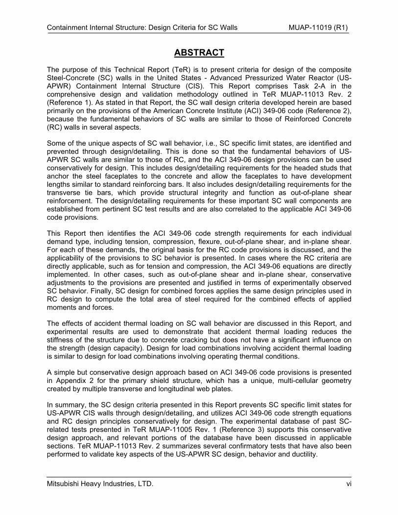
The purpose of this Technical Report (TeR) is to present criteria for design of the composite Steel-Concrete (SC) walls in the United States - Advanced Pressurized Water Reactor (US-APWR) Containment Internal Structure (CIS). This Report comprises Task 2-A in the comprehensive design and validation methodology outlined in TeR MUAP-11013 Rev. 2 (Reference 1). As stated in that Report, the SC wall design criteria developed herein are based primarily on the provisions of the American Concrete Institute (ACI) 349-06 code (Reference 2), because the fundamental behaviors of SC walls are similar to those of Reinforced Concrete (RC) walls in several aspects.
Some of the unique aspects of SC wall behavior, i.e., SC specific limit states, are identified and prevented through design/detailing. This is done so that the fundamental behaviors of US-APWR SC walls are similar to those of RC, and the ACI 349-06 design provisions can be used conservatively for design. This includes design/detailing requirements for the headed studs that anchor the steel faceplates to the concrete and allow the faceplates to have development lengths similar to standard reinforcing bars. It also includes design/detailing requirements for the transverse tie bars, which provide structural integrity and function as out-of-plane shear reinforcement. The design/detailing requirements for these important SC wall components are established from pertinent SC test results and are also correlated to the applicable ACI 349-06 code provisions.
This Report then identifies the ACI 349-06 code strength requirements for each individual demand type, including tension, compression, flexure, out-of-plane shear, and in-plane shear. For each of these demands, the original basis for the RC code provisions is discussed, and the applicability of the provisions to SC behavior is presented. In cases where the RC criteria are directly applicable, such as for tension and compression, the ACI 349-06 equations are directly implemented. In other cases, such as out-of-plane shear and in-plane shear, conservative adjustments to the provisions are presented and justified in terms of experimentally observed SC behavior. Finally, SC design for combined forces applies the same design principles used in RC design to compute the total area of steel required for the combined effects of applied moments and forces.
The effects of accident thermal loading on SC wall behavior are discussed in this Report, and experimental results are used to demonstrate that accident thermal loading reduces the stiffness of the structure due to concrete cracking but does not have a significant influence on the strength (design capacity). Design for load combinations involving accident thermal loading is similar to design for load combinations involving operating thermal conditions.
A simple but conservative design approach based on ACI 349-06 code provisions is presented in Appendix 2 for the primary shield structure, which has a unique, multi-cellular geometry created by multiple transverse and longitudinal web plates.
In summary, the SC design criteria presented in this Report prevents SC specific limit states for US-APWR CIS walls through design/detailing, and utilizes ACI 349-06 code strength equations and RC design principles conservatively for design. The experimental database of past SC-related tests presented in TeR MUAP-11005 Rev. 1 (Reference 3) supports this conservative design approach, and relevant portions of the database have been discussed in applicable sections. TeR MUAP-11013 Rev. 2 summarizes several confirmatory tests that have also been performed to validate key aspects of the US-APWR SC design, behavior and ductility.
Containment Internal Structure: Design Criteria for SC Walls MUAP-11019 (R1)
Mitsubishi Heavy Industries, LTD. vii
DESIGN PHILOSOPHY AND EXECUTIVE SUMMARY
The US-APWR CIS utilizes composite SC construction instead of conventional RC, in order to improve construction speed, economy, and structural efficiency. SC construction typically involves the use of steel faceplates acting compositely with concrete infill, while conventional RC construction involves the use of deformed steel reinforcing bars that are embedded in the concrete with adequate clear cover. The design of RC structures for safety-related nuclear facilities is governed by the ACI 349-06 code provisions. There is currently no such design code for SC structures in the US.
Experimental and analytical research of the fundamental behavior of SC walls subjected to different loading conditions (axial compression, flexure, out-of-plane shear, in-plane shear etc.) has been extensively conducted in Japan over the past 25 years. TeR MUAP-11005 Rev. 1 (Reference 3) presents some of the major research findings and accomplishments. It includes experimental and analytical results from: (i) 1/10th scale test of a related Pressurized Water Reactor CIS subjected to cyclic lateral loading, (ii) 1/6th scale test of the US-APWR CIS primary shield structure subjected to cyclic lateral loading, (iii) in-plane shear tests of SC walls with and without flanges, and with and without axial compression, (iv) out-of-plane shear tests of SC beams with and without tie bars, (v) axial compression tests of SC squat columns, and (vi) accident thermal load tests of SC walls panels.
The experimental investigations in TeR MUAP-11005 Rev. 1 cover a wide range of parameters, such as steel reinforcement ratios of 1.5% to 5% (2·tp/T, where tp = faceplate thickness and T = section thickness), shear connector spacing to faceplate thickness ratios of 20 to 50, with or without tie bars, and section thickness up to 24 in.
These experimental results identify some SC specific failure modes, such as (i) local buckling of the steel faceplates, (ii) interfacial shear failure of the connectors used to anchor the steel faceplates to the concrete infill, and (iii) splitting or delamination failure of the composite section through the concrete infill. Additionally, these experimental results show that if the SC specific failure modes are prevented, then the fundamental behavior of SC walls is similar to that of RC walls with comparable reinforcement ratio. For example, under flexural loading plane sections remain plane and perpendicular to the neutral axis, and concrete cracking has little influence on moment capacity. Out-of-plane behavior is governed by shear cracking of the concrete, and the yield strength of the tie bars through which the cracks pass. The in-plane behavior is governed by the yield strength of the steel faceplates and the orthogonal cracking of the concrete infill. These fundamental behaviors have been studied and demonstrated by researchers in the US. For example several research papers are included in MUAP-11005 Rev. 1 (Reference 3).
The design philosophy for these SC walls is to: (i) prevent SC specific failure modes and limit states by designing and detailing the section adequately, (ii) demonstrate the conservativeness of ACI 349-06 code equations for the strength of equivalent SC walls using experimental results, and (iii) to design them using more conservative forms of ACI 349-06 code equations and combined force design approaches for RC structures.
Containment Internal Structure: Design Criteria for SC Walls MUAP-11019 (R1)
Mitsubishi Heavy Industries, LTD. viii
The steel faceplates are anchored to the concrete using steel headed stud anchors (also referred to as shear studs) made from American Society for Testing and Materials (ASTM) [ ] The shear strength of these studs is computed using ACI 349-06 Appendix D recommendations for headed studs used within cast-in-place concrete. The spacing and strength of these shear studs is designed to achieve a reasonable development length for the steel faceplates that is comparable to the development lengths of #11, #14, or #18 deformed rebars typically used in RC structures. This is done primarily to achieve congruence with conventional RC design and detailing practices. It further ensures that the behavior of the US-APWR SC walls will be similar to those of equivalent RC walls.
The interfacial shear strength of the SC wall steel faceplates is governed by the strength and spacing of the shear studs. Therefore, the stud spacing and strength are further designed to prevent interfacial shear failure as an SC specific limit state. This is done by designing the interfacial shear strength (of the shear studs) to be greater than the corresponding out-of-plane shear strength of the SC section. This makes out-of-plane shear the governing failure mode for out-of-plane moment gradient demands, and prevents interfacial shear failure as a limit state.
Steel tie bars are provided to connect the two exterior steel faceplates through the concrete infill. These steel tie bars provide structural integrity to the SC section and prevent SC specific delamination or splitting failure mode from occurring. For the US-APWR SC walls these tie bars are made from [ ] As described in greater detail in TeR MUAP-11020 Rev. 1, the cross-sectional area and spacing of the tie bars are designed to prevent nonductile failure modes from occurring in the connection regions in the event of overload. The tie bar area and spacing are selected using the shear reinforcement strength and minimum spacing provisions of ACI 349-06 Section 11.5.[ ] For simplified fabrication and consistent out-of-plane shear behavior, the connection region tie bar size and spacing is maintained throughout the expanse of the SC walls.
The steel tie bars are further detailed to develop ductile yielding in axial tension before eventual fracture failure. Each tie bar through the SC section consists of two pieces, including a widened gusset plate at one end and a widened (“dogbone”) configuration at the other end (See Figure 2.8-1). These pieces are fillet welded to the opposite steel faceplates with sufficient weld strength to develop the expected tie bar tensile strength.
Thus, the US-APWR SC walls are detailed to prevent SC specific failure modes such as steel faceplate local buckling, interfacial shear failure, and delamination or splitting failure from governing the design. The SC walls are further detailed to have faceplate development lengths that are comparable to those of equivalent RC walls, and detailed with ductile tie bar systems that are fabricated and welded to the faceplates using reliable and straightforward structural steel fabrication methods. The tie bar systems are detailed to ensure that nonductile shear failure modes are prevented while meeting the ACI 349-06 minimum tie bar spacing
Containment Internal Structure: Design Criteria for SC Walls MUAP-11019 (R1)
Mitsubishi Heavy Industries, LTD. ix
requirements, as explained in greater detail in TeR MUAP-11020 Rev. 1 (Reference 4). The tie bars are not included in the interfacial shear strength or development length calculations, which are conservatively based on the shear studs alone.
The SC walls detailed as described above have fundamental behavior similar to that of equivalent RC walls, and can be designed according to applicable ACI 349-06 code provisions after demonstrating their conservativeness using SC experimental results.
The axial tension design strength (Tn), axial compression design strength (Pn), and the flexure design strength (Mn) of SC walls can be calculated using applicable ACI 349-06 code recommendations. The conservativeness of these ACI 349-06 code equations are demonstrated using available experimental results for axial compression and flexure capacity.
SC wall sections subjected to flexure are doubly reinforced with steel plates on both the compression and tension sides. The contribution of the compression steel reinforcement to the flexural design strength is disregarded as part of the conservative design philosophy, except in special cases involving very high axial compressive forces. For cases with very high axial compression, the tension reinforcement is conservatively disregarded, as further discussed below.
The out-of-plane shear strength of SC wall sections can be calculated using applicable ACI 349-06 code equations (i.e., Equation 11-2: Vn=Vc+Vs). However, these equations do not appropriately reflect the effects of section depth (size) on the shear strength contribution of the concrete infill (Vc). Therefore, the ACI 349-06 code equation for Vc is further reduced based on experimental results in order to be more conservative. Furthermore, the effects of axial tension or compression on the concrete contribution to out-of-plane shear strength can be calculated using the corresponding ACI 349-06 code equations. The shear strength contribution of the steel tie bars (Vs) can be calculated using ACI code equations because the tie bars are specifically detailed to develop their yield strength and ductility before fracture in axial tension. The conservativeness of the out-of-plane shear strength equations are demonstrated using available experimental results. Additional confirmatory tests were conducted to further demonstrate the conservatism of the out-of-plane shear strength equations for the US-APWR SC wall design, as summarized in TeR MUAP-11013 Rev. 2 (Reference 1).
The in-plane shear strength of SC walls can be calculated using applicable ACI 349-06 code equations (i.e., Equation 21-7: Vn = Acv[c f’c
0.5+tfy]). As an added conservatism, the contribution of the concrete infill to the in-plane shear strength (Acvcf’c
0.5) is ignored, and the in-plane shear strength is limited to the contribution of the steel faceplates only (Vn= Acv t fy = As fy). This in-plane shear strength equation compares conservatively with available experimental data for SC wall panels with reinforcement ratios from 2% – 4.5%, which is comparable to the range of reinforcement ratios of SC walls in the US-APWR CIS.
The experimental results for in-plane shear strength of SC walls do not demonstrate the upper bound limit (Vn = 10 Acv f’c
0.5) that is typically enforced for RC walls. This limit is enforced for RC walls to prevent overall failure caused by increasing crack widths under cyclic loading, overall crushing failure of the concrete compression struts in the wall, or sliding shear failure at the base. In spite of the experimental data, this upper bound limit is conservatively enforced for checking the overall in-plane shear strength of SC wall lengths.
Thus, the SC walls design strengths of various demand types (axial tension, compression, flexure, out-of-plane shear, and in-plane shear) are based on the ACI 349-06 code
Containment Internal Structure: Design Criteria for SC Walls MUAP-11019 (R1)
Mitsubishi Heavy Industries, LTD. x
recommendations with added conservatism where needed/appropriate. The conservatism of the ACI code equations are demonstrated using available experimental data. Confirmatory tests were also performed to further validate the conservatism of the out-of-plane shear strength equations for the US-APWR SC walls.
Since the US-APWR SC walls are detailed to prevent SC specific limit states, and SC behavior for individual force demands and corresponding design strengths are similar to those of RC walls, the design of SC walls for combined forces is done according to the same design philosophy and approach implemented conventionally for RC walls. As an added conservatism, the contribution of the concrete infill to the in-plane shear strength is also not included in the design calculations. Additionally, contribution of the steel reinforcement in compression is not included in the design calculations except in cases involving high axial compression, as discussed below.
The design for combined forces is based on a conservative interpretation of the conventional design of RC walls for combined forces. The design demands Nx, Ny, Nxy, Mx, My, and Mxy from the Finite Element (FE) analyses of the CIS (See Figure 8.0-1 for convention) are used to compute the total area of steel required in the x and y directions (Ax
req and Ayreq) as follows:
(i) Mxy is added to Mx and My so as to increase their magnitude for design. The increased design moments are referred to as Mx
total and Mytotal.
(ii) Nxy is used to compute area of steel required in both the x and y directions. The required area of shear reinforcement calculated is equal for both directions, and the area required in each direction is equally distributed on both faces. The contribution of the concrete infill to the in-plane shear strength is not included.
(iii) Section analysis is used to identify the balance point where the combination of axial force (Nbal) and moment (M) causes simultaneous: (a) steel yielding in tension, and (b) concrete compression strain of 0.003.
(iv) When the applied axial force is tensile, or compressive but less than the force corresponding to the balance point (Nbal), then the contribution of the steel compression reinforcement to the flexural resistance is ignored.
(v) When the applied axial force in compression is greater than Nbal, then the contribution of the steel compression reinforcement to the flexural resistance is considered, but the contribution of the steel tension reinforcement to the flexural resistance is ignored.
(vi) If N is less than Nbal, then N and Mtotal are used to compute the area of steel required. The area of steel required for Mtotal is calculated assuming no contribution from the compression reinforcement, but the calculated area is added to both faces (tensile and compressive).
(vii) If N is greater than Nbal, then N and Mtotal are used to compute the area of steel required. The area of steel required for Mtotal is calculated assuming no contribution from the reinforcement in tension, but the calculated area is added to both faces (tensile and compressive).
Finally, the total area of steel required is computed on both faces, and in both directions (Axreq
and Ayreq), and compared with the area of steel available on both faces in both directions (Ax
avail and Ay
avail). The Tresca yield criterion is considered during this step to establish rules for calculating the total areas of reinforcement required based on the biaxial state of stress imparted by the design demands.

Containment Internal Structure: Design Criteria for SC Walls MUAP-11019 (R1)
Mitsubishi Heavy Industries, LTD. xi
The design for loading combinations involving accident thermal loading is similar to the design for loading combinations involving operating thermal loading conditions only. Experimental results indicate that accident thermal loading produces nonlinear (parabolic) thermal gradients and extensive cracking through the concrete cross-section. This through section cracking reduces the section stiffness, but does not have a significant influence on the out-of-plane shear strength, flexure capacity, or in-plane shear strength of the SC walls. The effects of stiffness reduction on the design force demands (Nx, Ny, etc.) are included directly in the FE models as described in TeR MUAP-11018 Rev. 1 (Reference 5).
Since accident thermal loads do not have a significant influence on the SC wall design strengths, the same conservative design approach described above is used for the design of loading combinations involving accident thermal loading conditions.
Containment Internal Structure: Design Criteria for SC Walls MUAP-11019 (R1)
Mitsubishi Heavy Industries, LTD. 1-1
1.0 SC WALLS IN US-APWR CIS
1.1 SC Wall Dimensions
Table 1.1-1 summarizes the SC wall thicknesses used for the secondary shield walls in the CIS.
Table 1.1-1 SC Walls Thickness for CIS
Containment Internal Structure: Design Criteria for SC Walls MUAP-11019 (R1)
Mitsubishi Heavy Industries, LTD. 1-2
Figure 1.1-1 Primary Shield Wall Geometry
(a)Finite Element Model Showing Plate Thicknesses (b) Plan View Drawing of Primary Shield Showing Plates Between Elevations 16’-0” and 35’-11”
Containment Internal Structure: Design Criteria for SC Walls MUAP-11019 (R1)
Mitsubishi Heavy Industries, LTD. 1-3
1.2 General Design Approach and MUAP-11019 Purpose
There are three fundamental aspects of the overall design approach for the CIS SC walls, including: 1) detailing the SC walls to ensure that SC-specific limit states and failure modes do not govern the design, 2) designing the SC walls for their applied forces and moments using conservative forms of ACI 349-06 strength equations which are validated by experimental results, and 3) designing the SC wall connections and connection regions, which are those portions of the walls outside of the connections that are intended to dissipate energy through ductile inelastic response in the event of overloading.
The purpose of this Report is to address the first two aspects of the overall design approach; i.e., to explain the manner in which SC-specific limit states and failure modes are prevented, and to develop the conservative forms of ACI 349-06 equations to be used in designing the SC walls for their applied forces and moments. The third aspect of the overall design approach pertaining to design and detailing of the SC wall connections and connection regions is developed in TeR MUAP-11020 Rev. 1 (Reference 4).
Containment Internal Structure: Design Criteria for SC Walls MUAP-11019 (R1)
Mitsubishi Heavy Industries, LTD. 1-4
1.3 Report Outline
The main body of this Report is meant for the design of the single-core SC walls that function as the secondary shielding in the CIS. Appendix 2 ("Design Criteria for Primary Shield Structure") of this Report addresses the design of the SC walls that form the primary shield structure. This Appendix follows the design criteria presented in this Report (Sections 2 – 8) with some additional conservative assumptions.
Section 2 of this Report address SC specific design issues, for example, local buckling of the steel faceplates, composite action between steel faceplates and concrete infill, and structural integrity of the composite section.
Sections 3, 4, and 5 of this Report include design strength equations for axial tension, axial compression, and flexural moment demands. These design strength equations are based directly on the ACI 349-06 code recommendations for RC walls.
Section 6 of this Report presents design strength equations for out-of-plane shear. These equations are based on the ACI 349-06 code recommendations for RC walls, but they include further conservatism to address size and scale effects.
Section 7 of this Report presents the design strength equations for in-plane shear. These equations are also based on the ACI 349-06 code recommendations for RC walls, but they also include further conservatism based on existing SC wall test results.
Section 8 of this Report presents the approach for designing these SC walls for combined forces (axial tension or compression, flexure, and in-plane shear in either direction). It also includes the approach for designing these SC walls for out-of-plane shears in both (horizontal and vertical) directions.
Section 9 of this Report discusses SC design considerations for accident thermal loading. It is shown that accident thermal loads do not have a significant influence on the strength (axial tension, compression, flexure, out-of-plane shear, and in-plane shear strength) of SC walls. This is demonstrated using test results from Japan and the U.S.
Section 10 lists References cited in this Report. Note that Appendix E of MUAP-11005 Rev. 1 (Reference 3) contains the SC research reports related to out-of-plane shear behavior, in-plane shear behavior, axial compression and local buckling behavior, and design of SC walls for thermal effects.
Appendix 1 presents sample calculations of reinforcement requirements that demonstrate implementation of the design approach for combined forces outlined in Section 8.0.
Appendix 2 provides the additional design criteria specific to the primary shield structure.
Containment Internal Structure: Design Criteria for SC Walls MUAP-11019 (R1)
Mitsubishi Heavy Industries, LTD. 2-1
2.0 SC SPECIFIC DESIGN ISSUES AND SECTION DETAILING
2.1 Section Details
Figure 2.1-1 Stud and Tie Bar Grid Pattern on Steel Faceplates
The behavior and design of SC modules is similar to that of RC walls, as will be discussed in detail in subsequent sections. However, there are several SC specific design issues involving behaviors that are different from typical RC behavior, including: (i) local buckling of steel faceplates, (ii) shear connector strength and spacing, (iii) development length, (iv) tie bar spacing, (v) tie bar ductility, and (vi) faceplate penetration detailing. The following design criteria are used to address these SC specific design issues.
2.2 Local Buckling of Steel Faceplates
The steel faceplates of SC walls are outside of the concrete infill and can potentially undergo local buckling when subjected to compressive stresses. Since the steel faceplates are anchored to the concrete infill using shear studs and tie bars, local buckling can only occur in between these anchor points as shown in Figure 2.2-1. The ratio s/tp defines the slenderness ratio and controls the critical buckling stress of the steel faceplate.
Containment Internal Structure: Design Criteria for SC Walls MUAP-11019 (R1)
Mitsubishi Heavy Industries, LTD. 2-2
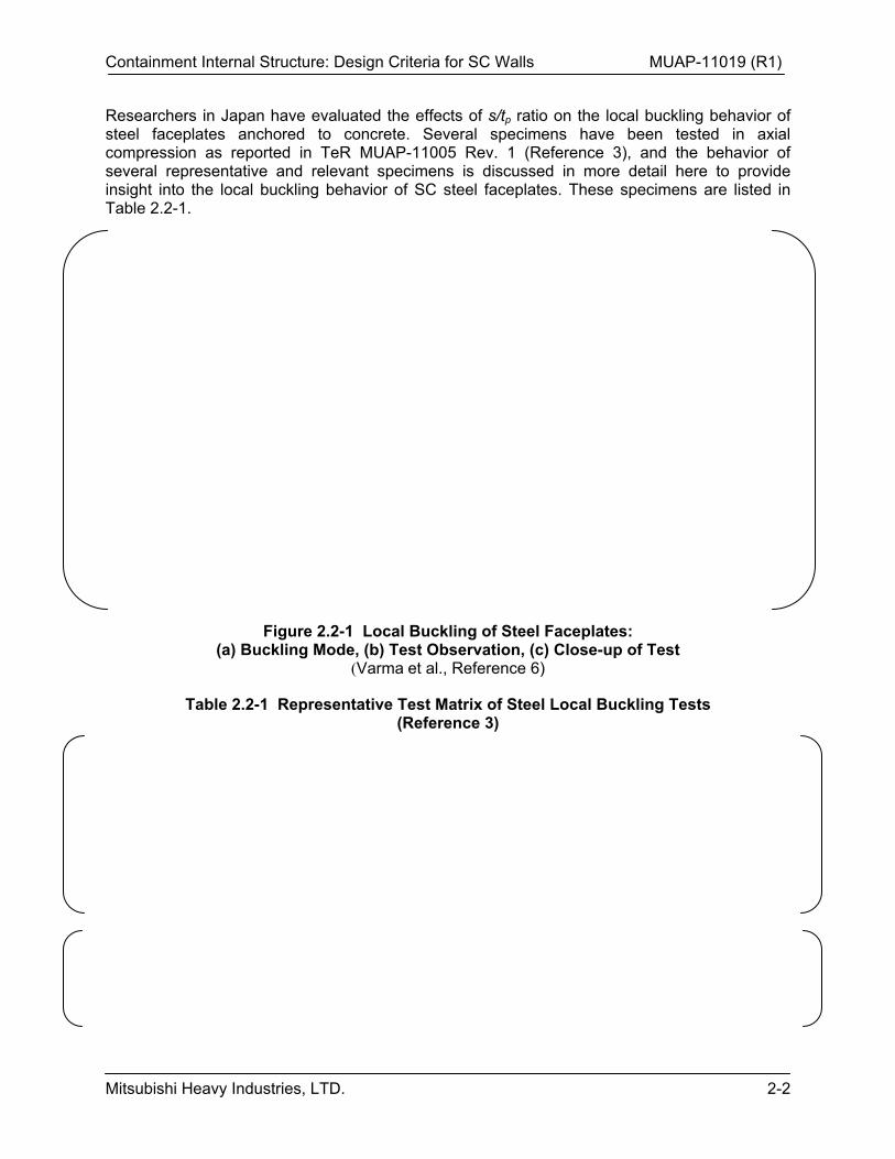
Researchers in Japan have evaluated the effects of s/tp ratio on the local buckling behavior of steel faceplates anchored to concrete. Several specimens have been tested in axial compression as reported in TeR MUAP-11005 Rev. 1 (Reference 3), and the behavior of several representative and relevant specimens is discussed in more detail here to provide insight into the local buckling behavior of SC steel faceplates. These specimens are listed in Table 2.2-1.
Figure 2.2-1 Local Buckling of Steel Faceplates: (a) Buckling Mode, (b) Test Observation, (c) Close-up of Test
(Varma et al., Reference 6)
Table 2.2-1 Representative Test Matrix of Steel Local Buckling Tests (Reference 3)
Containment Internal Structure: Design Criteria for SC Walls MUAP-11019 (R1)
Mitsubishi Heavy Industries, LTD. 2-3
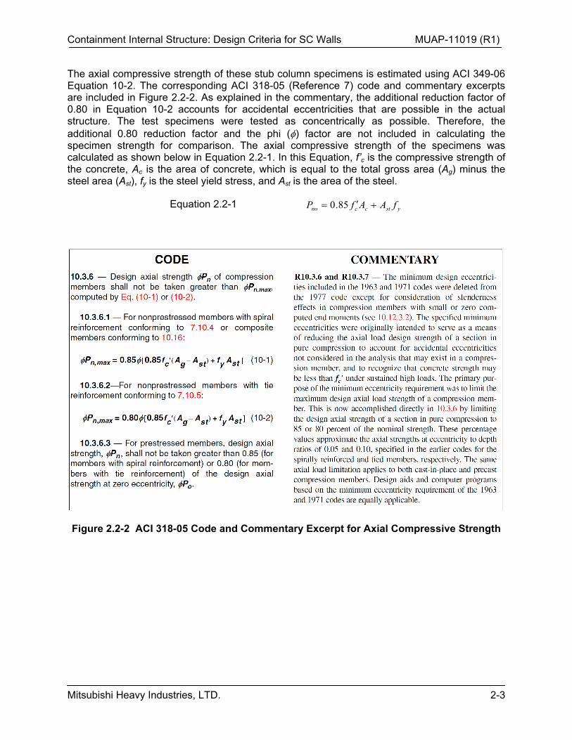
The axial compressive strength of these stub column specimens is estimated using ACI 349-06 Equation 10-2. The corresponding ACI 318-05 (Reference 7) code and commentary excerpts are included in Figure 2.2-2. As explained in the commentary, the additional reduction factor of 0.80 in Equation 10-2 accounts for accidental eccentricities that are possible in the actual structure. The test specimens were tested as concentrically as possible. Therefore, the additional 0.80 reduction factor and the phi () factor are not included in calculating the specimen strength for comparison. The axial compressive strength of the specimens was calculated as shown below in Equation 2.2-1. In this Equation, f’c is the compressive strength of the concrete, Ac is the area of concrete, which is equal to the total gross area (Ag) minus the steel area (Ast), fy is the steel yield stress, and Ast is the area of the steel.
Equation 2.2-1 ystccno fAAfP 85.0
Figure 2.2-2 ACI 318-05 Code and Commentary Excerpt for Axial Compressive Strength
Containment Internal Structure: Design Criteria for SC Walls MUAP-11019 (R1)
Mitsubishi Heavy Industries, LTD. 2-4
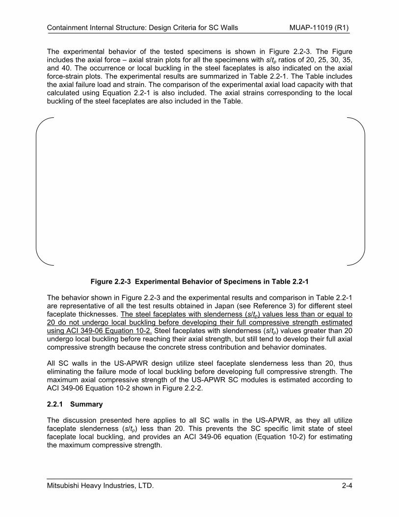
The experimental behavior of the tested specimens is shown in Figure 2.2-3. The Figure includes the axial force – axial strain plots for all the specimens with s/tp ratios of 20, 25, 30, 35, and 40. The occurrence or local buckling in the steel faceplates is also indicated on the axial force-strain plots. The experimental results are summarized in Table 2.2-1. The Table includes the axial failure load and strain. The comparison of the experimental axial load capacity with that calculated using Equation 2.2-1 is also included. The axial strains corresponding to the local buckling of the steel faceplates are also included in the Table.
Figure 2.2-3 Experimental Behavior of Specimens in Table 2.2-1
The behavior shown in Figure 2.2-3 and the experimental results and comparison in Table 2.2-1 are representative of all the test results obtained in Japan (see Reference 3) for different steel faceplate thicknesses. The steel faceplates with slenderness (s/tp) values less than or equal to 20 do not undergo local buckling before developing their full compressive strength estimated using ACI 349-06 Equation 10-2. Steel faceplates with slenderness (s/tp) values greater than 20 undergo local buckling before reaching their axial strength, but still tend to develop their full axial compressive strength because the concrete stress contribution and behavior dominates.
All SC walls in the US-APWR design utilize steel faceplate slenderness less than 20, thus eliminating the failure mode of local buckling before developing full compressive strength. The maximum axial compressive strength of the US-APWR SC modules is estimated according to ACI 349-06 Equation 10-2 shown in Figure 2.2-2.
2.2.1 Summary
The discussion presented here applies to all SC walls in the US-APWR, as they all utilize faceplate slenderness (s/tp) less than 20. This prevents the SC specific limit state of steel faceplate local buckling, and provides an ACI 349-06 equation (Equation 10-2) for estimating the maximum compressive strength.
Containment Internal Structure: Design Criteria for SC Walls MUAP-11019 (R1)
Mitsubishi Heavy Industries, LTD. 2-5
2.3 Shear Connector Strength and Spacing
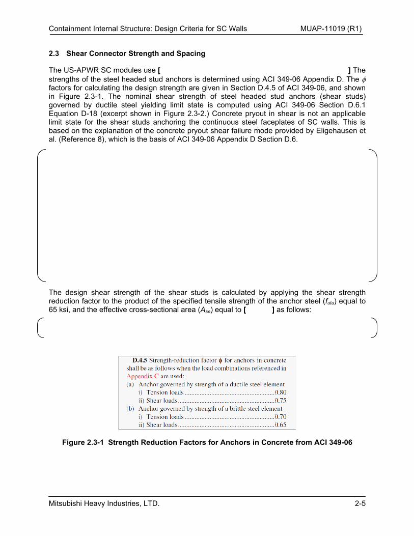
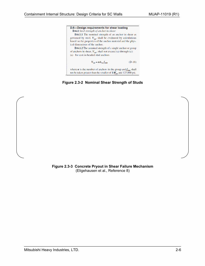
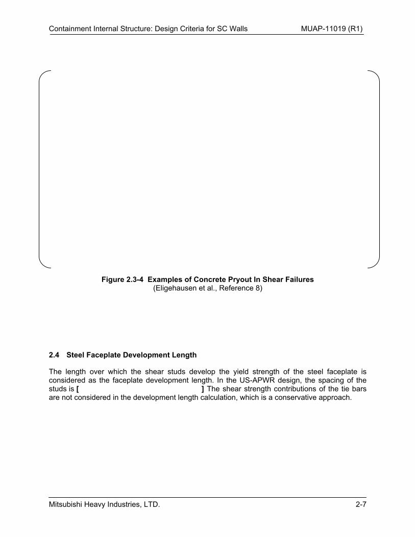
The US-APWR SC modules use [ ] The strengths of the steel headed stud anchors is determined using ACI 349-06 Appendix D. The factors for calculating the design strength are given in Section D.4.5 of ACI 349-06, and shown in Figure 2.3-1. The nominal shear strength of steel headed stud anchors (shear studs) governed by ductile steel yielding limit state is computed using ACI 349-06 Section D.6.1 Equation D-18 (excerpt shown in Figure 2.3-2.) Concrete pryout in shear is not an applicable limit state for the shear studs anchoring the continuous steel faceplates of SC walls. This is based on the explanation of the concrete pryout shear failure mode provided by Eligehausen et al. (Reference 8), which is the basis of ACI 349-06 Appendix D Section D.6.
The design shear strength of the shear studs is calculated by applying the shear strength reduction factor to the product of the specified tensile strength of the anchor steel (futa) equal to 65 ksi, and the effective cross-sectional area (Ase) equal to [ ] as follows:
Figure 2.3-1 Strength Reduction Factors for Anchors in Concrete from ACI 349-06
Containment Internal Structure: Design Criteria for SC Walls MUAP-11019 (R1)
Mitsubishi Heavy Industries, LTD. 2-6
Figure 2.3-2 Nominal Shear Strength of Studs
Figure 2.3-3 Concrete Pryout in Shear Failure Mechanism (Eligehausen et al., Reference 8)
Containment Internal Structure: Design Criteria for SC Walls MUAP-11019 (R1)
Mitsubishi Heavy Industries, LTD. 2-7
Figure 2.3-4 Examples of Concrete Pryout In Shear Failures (Eligehausen et al., Reference 8)
2.4 Steel Faceplate Development Length
The length over which the shear studs develop the yield strength of the steel faceplate is considered as the faceplate development length. In the US-APWR design, the spacing of the studs is [ ] The shear strength contributions of the tie bars are not considered in the development length calculation, which is a conservative approach.
Containment Internal Structure: Design Criteria for SC Walls MUAP-11019 (R1)
Mitsubishi Heavy Industries, LTD. 2-8
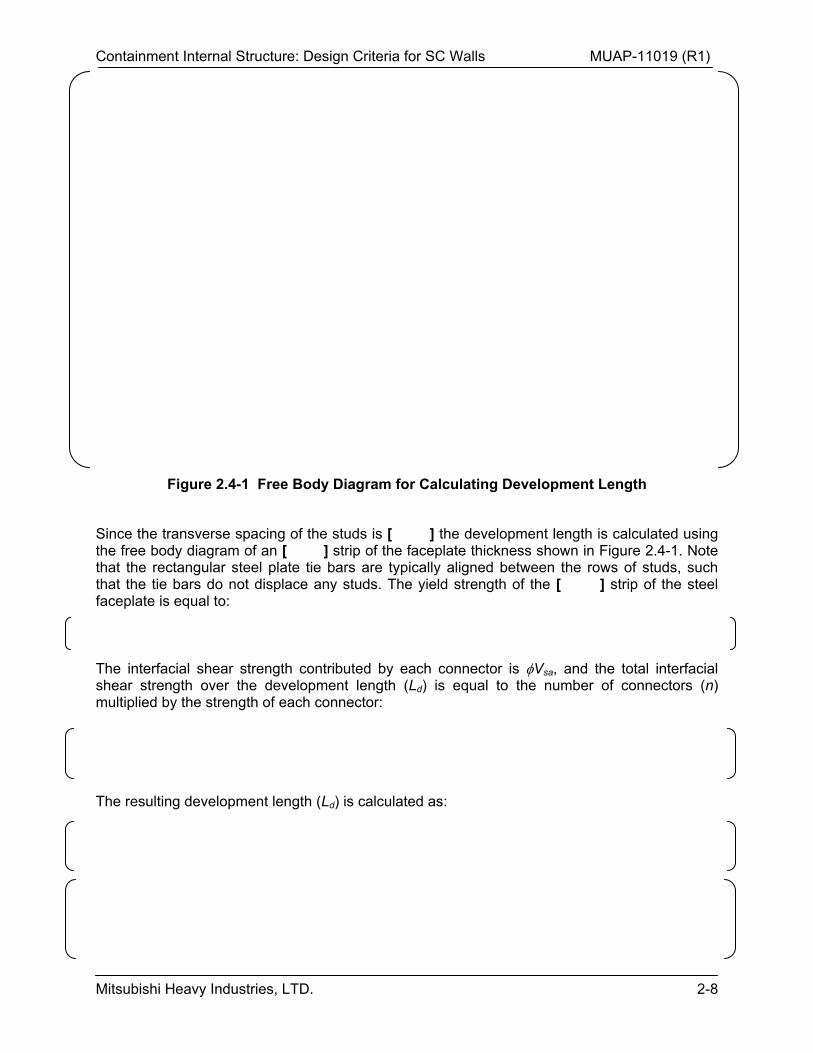
Figure 2.4-1 Free Body Diagram for Calculating Development Length
Since the transverse spacing of the studs is [ ] the development length is calculated using the free body diagram of an [ ] strip of the faceplate thickness shown in Figure 2.4-1. Note that the rectangular steel plate tie bars are typically aligned between the rows of studs, such that the tie bars do not displace any studs. The yield strength of the [ ] strip of the steel faceplate is equal to:
The interfacial shear strength contributed by each connector is Vsa, and the total interfacial shear strength over the development length (Ld) is equal to the number of connectors (n) multiplied by the strength of each connector:
The resulting development length (Ld) is calculated as:
Containment Internal Structure: Design Criteria for SC Walls MUAP-11019 (R1)
Mitsubishi Heavy Industries, LTD. 2-9
2.4.1 Summary
The calculated development length for steel faceplate of SC modules is approximately equal to the typical development lengths for #14 rebars calculated using ACI code provisions, and used typically in RC nuclear structures.
2.5 Interfacial Shear Strength
The interfacial shear strength of the shear connectors between the steel faceplates and the concrete infill is calculated by continuing the discussion presented in Section 2.4. The design shear strength of each shear stud was calculated as Vsa.
[ ] Although this is not meant to represent any specific equation or formula for the interfacial shear strength for SC modules, it is indicative of the relative strength of the SC sections for interfacial shear. This calculation does not include the contribution of the tie bars, which is part of the conservative design approach presented here.
The design philosophy for SC modules is to maintain the requirement that the interfacial shear strength must be greater than the out-of-plane shear strength of the SC section. As a result, an interfacial shear failure mode will not occur prior to an out-of-plane shear failure mode under applied transverse loading. Thus, the SC specific limit state of interfacial shear failure is prevented from occurring.
[ ] The out-of-plane design shear strength for these typical SC walls is calculated in Equation 2.5-1 below, using equations from Section 6.0.
Containment Internal Structure: Design Criteria for SC Walls MUAP-11019 (R1)
Mitsubishi Heavy Industries, LTD. 2-10
As demonstrated above, the interfacial shear strength [ ] is greater than the corresponding out-of-plane shear strength [ ] for typical SC modules. This prevents the interfacial shear failure mode for the typical SC modules, but it must be checked for all SC walls and locations.
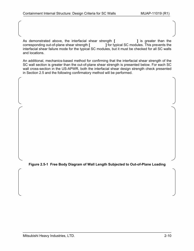
An additional, mechanics-based method for confirming that the interfacial shear strength of the SC wall section is greater than the out-of-plane shear strength is presented below. For each SC wall cross-section in the US-APWR, both the interfacial shear design strength check presented in Section 2.5 and the following confirmatory method will be performed.
Figure 2.5-1 Free Body Diagram of Wall Length Subjected to Out-of-Plane Loading
Containment Internal Structure: Design Criteria for SC Walls MUAP-11019 (R1)
Mitsubishi Heavy Industries, LTD. 2-11
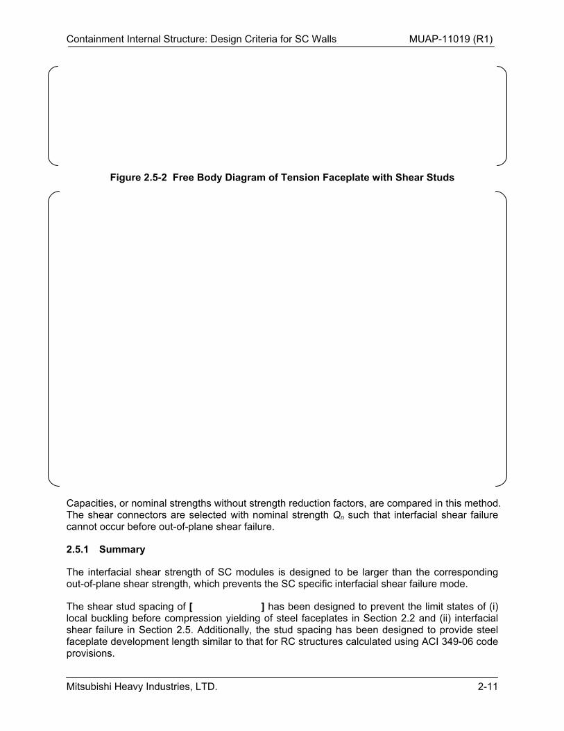
Figure 2.5-2 Free Body Diagram of Tension Faceplate with Shear Studs
Capacities, or nominal strengths without strength reduction factors, are compared in this method. The shear connectors are selected with nominal strength Qn such that interfacial shear failure cannot occur before out-of-plane shear failure.
2.5.1 Summary
The interfacial shear strength of SC modules is designed to be larger than the corresponding out-of-plane shear strength, which prevents the SC specific interfacial shear failure mode.
The shear stud spacing of [ ] has been designed to prevent the limit states of (i) local buckling before compression yielding of steel faceplates in Section 2.2 and (ii) interfacial shear failure in Section 2.5. Additionally, the stud spacing has been designed to provide steel faceplate development length similar to that for RC structures calculated using ACI 349-06 code provisions.
Containment Internal Structure: Design Criteria for SC Walls MUAP-11019 (R1)
Mitsubishi Heavy Industries, LTD. 2-12
2.6 Tie Bar Spacing and Size
Steel tie bars are needed in SC modules for the following reasons: (1) supporting the faceplates during concrete placement; (2) connecting the two steel faceplates through the concrete thickness, which is typically greater than [ ] for the US-APWR SC walls; (3) providing structural integrity by preventing delamination failure of the concrete infill; and (4) providing shear reinforcement when needed for resisting out-of-plane shear force. As discussed in TeR MUAP-11020 Rev. 1 (Reference 4), the size and spacing of the tie bars are determined by the connection and connection region design requirements which, for simplicity, are extended to the full expanse of the SC wall.
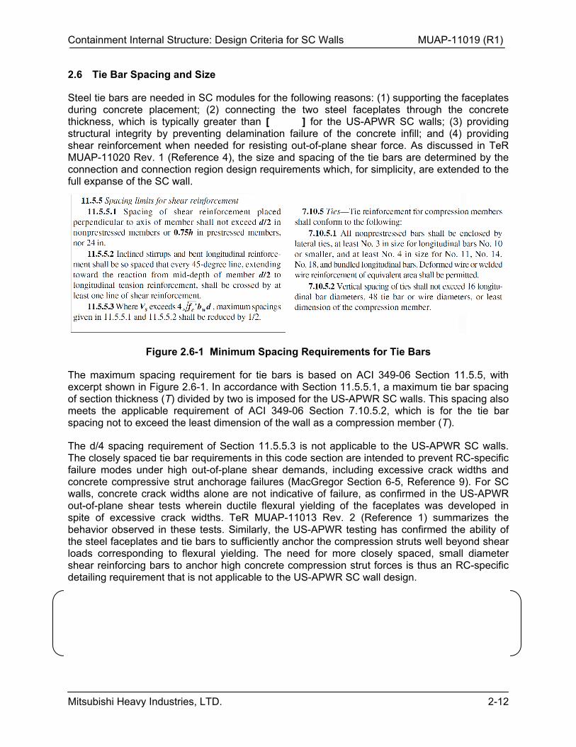
Figure 2.6-1 Minimum Spacing Requirements for Tie Bars
The maximum spacing requirement for tie bars is based on ACI 349-06 Section 11.5.5, with excerpt shown in Figure 2.6-1. In accordance with Section 11.5.5.1, a maximum tie bar spacing of section thickness (T) divided by two is imposed for the US-APWR SC walls. This spacing also meets the applicable requirement of ACI 349-06 Section 7.10.5.2, which is for the tie bar spacing not to exceed the least dimension of the wall as a compression member (T).
The d/4 spacing requirement of Section 11.5.5.3 is not applicable to the US-APWR SC walls. The closely spaced tie bar requirements in this code section are intended to prevent RC-specific failure modes under high out-of-plane shear demands, including excessive crack widths and concrete compressive strut anchorage failures (MacGregor Section 6-5, Reference 9). For SC walls, concrete crack widths alone are not indicative of failure, as confirmed in the US-APWR out-of-plane shear tests wherein ductile flexural yielding of the faceplates was developed in spite of excessive crack widths. TeR MUAP-11013 Rev. 2 (Reference 1) summarizes the behavior observed in these tests. Similarly, the US-APWR testing has confirmed the ability of the steel faceplates and tie bars to sufficiently anchor the compression struts well beyond shear loads corresponding to flexural yielding. The need for more closely spaced, small diameter shear reinforcing bars to anchor high concrete compression strut forces is thus an RC-specific detailing requirement that is not applicable to the US-APWR SC wall design.
Containment Internal Structure: Design Criteria for SC Walls MUAP-11019 (R1)
Mitsubishi Heavy Industries, LTD. 2-13
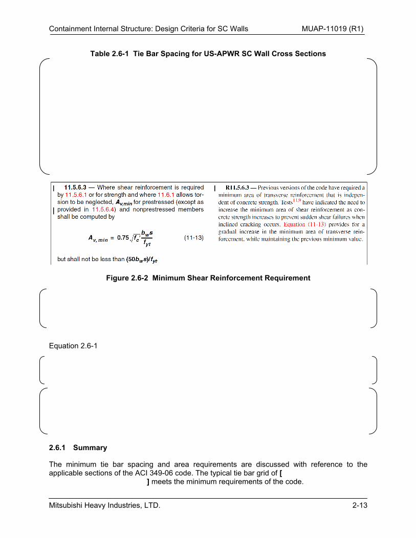
Table 2.6-1 Tie Bar Spacing for US-APWR SC Wall Cross Sections
Figure 2.6-2 Minimum Shear Reinforcement Requirement
Equation 2.6-1
2.6.1 Summary
The minimum tie bar spacing and area requirements are discussed with reference to the applicable sections of the ACI 349-06 code. The typical tie bar grid of [ ] meets the minimum requirements of the code.
Containment Internal Structure: Design Criteria for SC Walls MUAP-11019 (R1)
Mitsubishi Heavy Industries, LTD. 2-14
2.7 Delamination or Splitting Failure
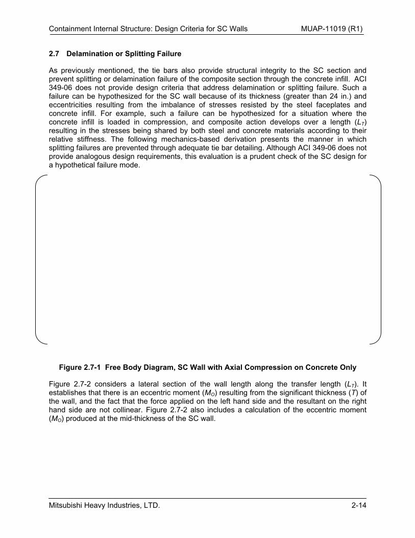
As previously mentioned, the tie bars also provide structural integrity to the SC section and prevent splitting or delamination failure of the composite section through the concrete infill. ACI 349-06 does not provide design criteria that address delamination or splitting failure. Such a failure can be hypothesized for the SC wall because of its thickness (greater than 24 in.) and eccentricities resulting from the imbalance of stresses resisted by the steel faceplates and concrete infill. For example, such a failure can be hypothesized for a situation where the concrete infill is loaded in compression, and composite action develops over a length (LT) resulting in the stresses being shared by both steel and concrete materials according to their relative stiffness. The following mechanics-based derivation presents the manner in which splitting failures are prevented through adequate tie bar detailing. Although ACI 349-06 does not provide analogous design requirements, this evaluation is a prudent check of the SC design for a hypothetical failure mode.
Figure 2.7-1 Free Body Diagram, SC Wall with Axial Compression on Concrete Only
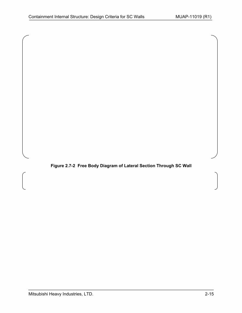
Figure 2.7-2 considers a lateral section of the wall length along the transfer length (LT). It establishes that there is an eccentric moment (MO) resulting from the significant thickness (T) of the wall, and the fact that the force applied on the left hand side and the resultant on the right hand side are not collinear. Figure 2.7-2 also includes a calculation of the eccentric moment (MO) produced at the mid-thickness of the SC wall.
Containment Internal Structure: Design Criteria for SC Walls MUAP-11019 (R1)
Mitsubishi Heavy Industries, LTD. 2-15
Figure 2.7-2 Free Body Diagram of Lateral Section Through SC Wall
Containment Internal Structure: Design Criteria for SC Walls MUAP-11019 (R1)
Mitsubishi Heavy Industries, LTD. 2-16
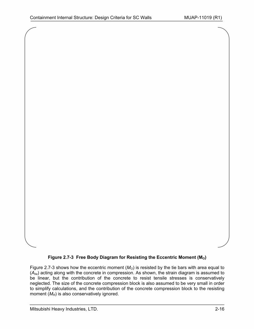
Figure 2.7-3 Free Body Diagram for Resisting the Eccentric Moment (MO)
Figure 2.7-3 shows how the eccentric moment (MO) is resisted by the tie bars with area equal to (Atie) acting along with the concrete in compression. As shown, the strain diagram is assumed to be linear, but the contribution of the concrete to resist tensile stresses is conservatively neglected. The size of the concrete compression block is also assumed to be very small in order to simplify calculations, and the contribution of the concrete compression block to the resisting moment (MR) is also conservatively ignored.
Containment Internal Structure: Design Criteria for SC Walls MUAP-11019 (R1)
Mitsubishi Heavy Industries, LTD. 2-17
As shown by the plan view in Figure 2.7-3, a unit portion of the wall with contributing tie bars is considered. The resisting moment MR is calculated by including the contributions of all the tie bars in the unit portion, as shown in the Figure. The resisting moment (MR) is estimated as shown in Figure 2.7-3, and listed below in Equation 2.7-1.
where, n = number of tie bars in the transfer length (LT), and SL is the longitudinal spacing of the tie bars, and Freq
n is the required strength in the tie bar. For example, if the transfer length is 3 times the wall thickness (T), and the longitudinal spacing of the tie bars is equal to the wall thickness (T/2), then n = 6.
The required tie bar strength (Freqn) is estimated by setting the resisting moment (MR) greater
than or equal to the eccentric moment (MO). The largest value for the eccentric moment (MO) is equal to the steel faceplate force [ ] The steel faceplate area is estimated using the width of the unit portion of the wall shown in Figure 2.7-3, i.e., ST x tp x Fy, where ST is the transverse spacing of the tie bars, tp is the plate thickness, and Fy is the yield stress of the tie bar steel.
It is important to note that the required force Freqn is a hypothetical demand that has been
posited to evaluate the structural integrity and splitting failure of the section. It is not a real force demand that needs to be deducted from the available capacity of the tie bar.
Additionally, the tie bars provide structural integrity when there is an imbalance in the forces in the thick composite cross-section due to different areas and yield strengths of the steel faceplates. For example, under in-plane shear loading, the composite section typically develops the yield strength of the section, which could imply slightly different yield forces in the steel plates due to differences in their actual areas or yield stresses.
Containment Internal Structure: Design Criteria for SC Walls MUAP-11019 (R1)
Mitsubishi Heavy Industries, LTD. 2-18
Figure 2.7-4 Eccentric Moment (MO) Due to Imbalance in Yield Forces of Steel Faceplates
The US-APWR SC walls typically have the same specified thickness and yield stress for opposing steel faceplates. Any force imbalance will primarily occur as a result of differences in actual thickness and yield stress behavior of opposing steel faceplates. As described above, the tie bars have more than sufficient capacity to prevent a splitting failure resulting from this imbalance.
2.7.1 Summary
Loss of structural integrity due to delamination or splitting failure is plausible for SC walls because of the imbalance of stresses resisted by the steel faceplates and the concrete infill, and because of the significant eccentricities associated with the large wall thicknesses used. ACI 349-06 does not provide design requirements to prevent splitting failure of large-thickness RC walls. Nevertheless, each US-APWR SC wall cross section is to be evaluated for two conditions resulting in eccentric moments that must be resisted by the tie bars to prevent delamination or splitting, including 1) eccentricity between applied and resisting forces in the composite section, and 2) eccentricity resulting from differences in opposing faceplate resisting forces due to small differences in actual plate thickness or yield stress. [ ] it has been shown that the tie bars have more than sufficient capacity to prevent splitting or delamination failure modes.
Containment Internal Structure: Design Criteria for SC Walls MUAP-11019 (R1)
Mitsubishi Heavy Industries, LTD. 2-19
2.8 Tie Bar Detailing
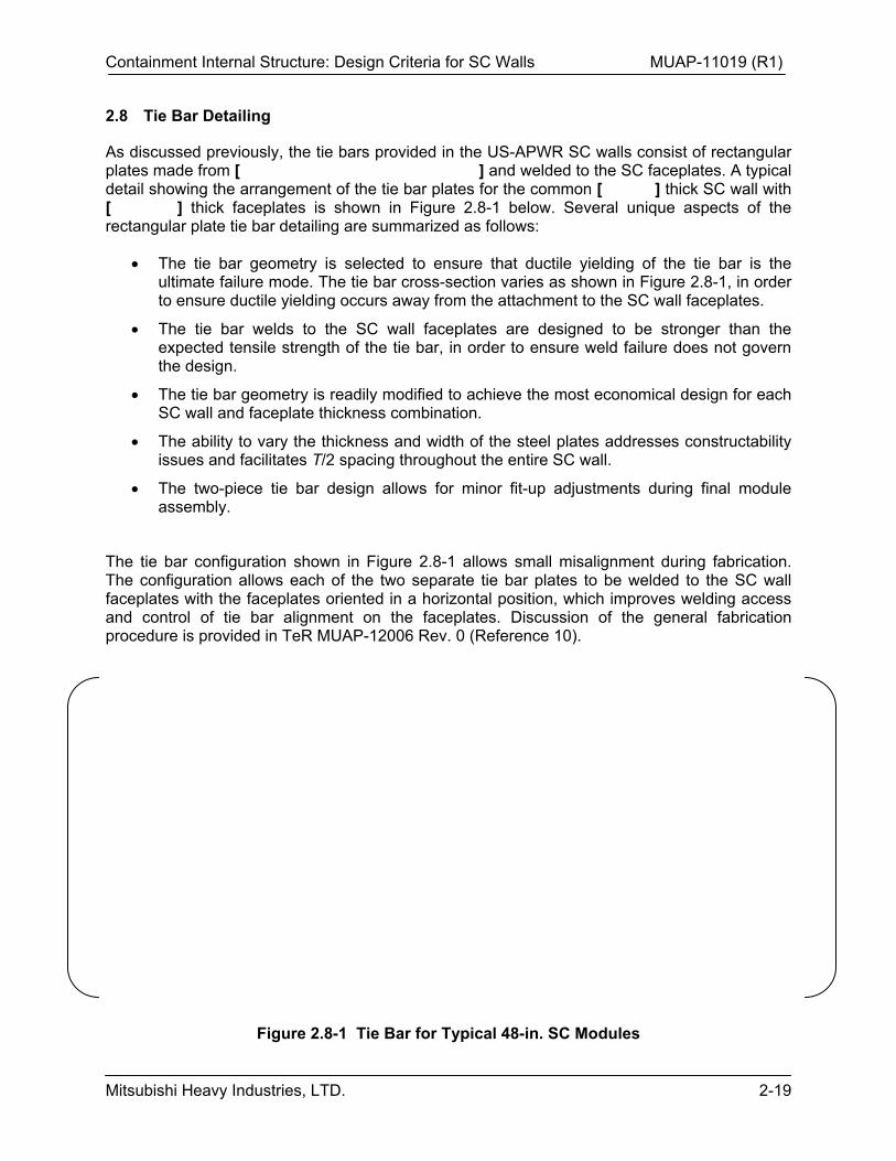
As discussed previously, the tie bars provided in the US-APWR SC walls consist of rectangular plates made from [ ] and welded to the SC faceplates. A typical detail showing the arrangement of the tie bar plates for the common [ ] thick SC wall with [ ] thick faceplates is shown in Figure 2.8-1 below. Several unique aspects of the rectangular plate tie bar detailing are summarized as follows:
The tie bar geometry is selected to ensure that ductile yielding of the tie bar is the ultimate failure mode. The tie bar cross-section varies as shown in Figure 2.8-1, in order to ensure ductile yielding occurs away from the attachment to the SC wall faceplates.
The tie bar welds to the SC wall faceplates are designed to be stronger than the expected tensile strength of the tie bar, in order to ensure weld failure does not govern the design.
The tie bar geometry is readily modified to achieve the most economical design for each SC wall and faceplate thickness combination.
The ability to vary the thickness and width of the steel plates addresses constructability issues and facilitates T/2 spacing throughout the entire SC wall.
The two-piece tie bar design allows for minor fit-up adjustments during final module assembly.
The tie bar configuration shown in Figure 2.8-1 allows small misalignment during fabrication. The configuration allows each of the two separate tie bar plates to be welded to the SC wall faceplates with the faceplates oriented in a horizontal position, which improves welding access and control of tie bar alignment on the faceplates. Discussion of the general fabrication procedure is provided in TeR MUAP-12006 Rev. 0 (Reference 10).
Figure 2.8-1 Tie Bar for Typical 48-in. SC Modules
Containment Internal Structure: Design Criteria for SC Walls MUAP-11019 (R1)
Mitsubishi Heavy Industries, LTD. 2-20
2.9 SC Faceplate Penetration Detailing
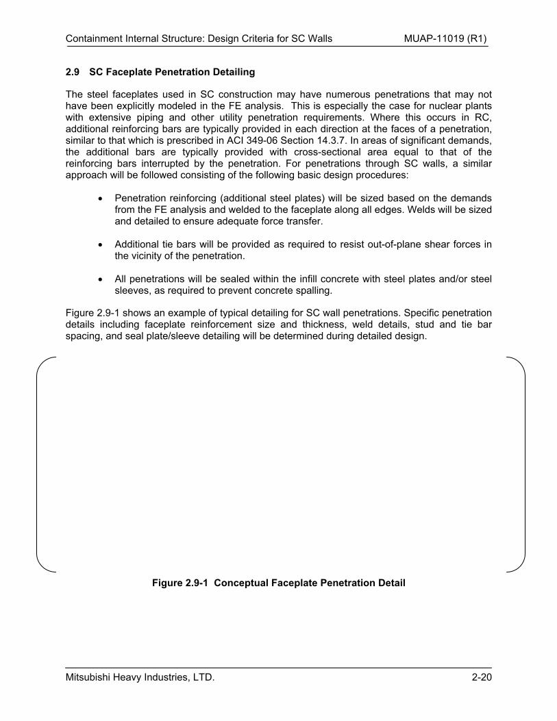
The steel faceplates used in SC construction may have numerous penetrations that may not have been explicitly modeled in the FE analysis. This is especially the case for nuclear plants with extensive piping and other utility penetration requirements. Where this occurs in RC, additional reinforcing bars are typically provided in each direction at the faces of a penetration, similar to that which is prescribed in ACI 349-06 Section 14.3.7. In areas of significant demands, the additional bars are typically provided with cross-sectional area equal to that of the reinforcing bars interrupted by the penetration. For penetrations through SC walls, a similar approach will be followed consisting of the following basic design procedures:
Penetration reinforcing (additional steel plates) will be sized based on the demands from the FE analysis and welded to the faceplate along all edges. Welds will be sized and detailed to ensure adequate force transfer.
Additional tie bars will be provided as required to resist out-of-plane shear forces in the vicinity of the penetration.
All penetrations will be sealed within the infill concrete with steel plates and/or steel sleeves, as required to prevent concrete spalling.
Figure 2.9-1 shows an example of typical detailing for SC wall penetrations. Specific penetration details including faceplate reinforcement size and thickness, weld details, stud and tie bar spacing, and seal plate/sleeve detailing will be determined during detailed design.
Figure 2.9-1 Conceptual Faceplate Penetration Detail
Containment Internal Structure: Design Criteria for SC Walls MUAP-11019 (R1)
Mitsubishi Heavy Industries, LTD. 2-21
2.10 Design for Commodity Support Loads
The SC walls in the US-APWR CIS will be utilized to support various plant commodities such as piping, electrical conduits, and cable trays. The loads imparted by commodity attachments to the SC faceplates must be considered in the design and detailing of the SC walls.
In RC construction, commodity supports are typically attached to structural concrete members using embedded steel plates anchored into the concrete with headed shear studs. Structural steel members such as tubes or wide-flange sections are then welded to the embedded plate to support the given piping or other plant commodity. The design of such commodity supports usually involves the following basic steps:
1) The welds between the embedded plate and the structural steel member supporting the commodity are sized for the demands applied by the structural steel member.
2) The thickness of the embedded plate is selected to provide sufficient flexural capacity for out-of-plane moments in the plate resulting from the relative distance between the welded structural member and the embedded shear studs.
3) The headed shear studs are sized and spaced to provide sufficient tension and shear resistance for the applied loads, using the anchorage design provisions of ACI 349-06 Appendix D.
4) The supporting structural concrete member (e.g., a structural wall or column) is confirmed to have sufficient capacity for the loads imparted by the commodity support in conjunction with other design loads.
Similarly, commodity supports on the SC walls in the US-APWR CIS will utilize structural steel members welded to attachment plates as in typical RC construction. However, the attachment plates will be detailed to transfer commodity forces into the SC wall directly via welds located only at the SC wall tie bar locations, as shown conceptually in Figure 2.10-1. This approach engages the full SC cross section via the tie bars, rather than applying tension to the studs and imparting flexure into the SC faceplate between the studs. As a result, the studs on the SC wall faceplate need not be designed for the combination of interfacial shear and applied tension, and the SC faceplate need not be designed for localized flexure between the studs. The design approach utilizing the detailing conceptually illustrated in Figure 2.10-1 will involve the following basic steps:
1) The welds between the attachment plate and the structural steel member provided for the commodity support will be sized for the demands applied by the structural steel member.
2) The thickness of the attachment plate will be selected to provide sufficient flexural capacity for out-of-plane moments in the plate resulting from the relative distance between the welded structural member and the supporting tie bars.
3) The welds between the attachment plate and the SC faceplate will be sized to transfer the applied loads to the supporting tie bars.
4) The supporting tie bars will be confirmed to have sufficient capacity for the combination of tension imparted by the commodity attachment and the SC wall out-
Containment Internal Structure: Design Criteria for SC Walls MUAP-11019 (R1)
Mitsubishi Heavy Industries, LTD. 2-22
of-plane shear demands resisted by the tie bars. Recognizing that out-of-plane shear demands on the wall result in tension in the tie bars, the commodity support tension per tie bar is combined directly with the tension per tie bar due to the local out-of-plane shear forces calculated in the FE analysis of the CIS (i.e., Vxz and Vyz discussed in Section 8.0 of this Report). The total demand will then be compared with the design strength of the tie bar (Avfy), calculated using the strength reduction factor for shear ( = 0.85 per ACI 349-06 Section C.3.2.3). Appropriate load factors from ACI 349-06 will be applied to the commodity support demands depending on the load case considered (e.g., dead load, pipe reaction loads, etc.)
5) The SC wall will be confirmed to have sufficient capacity for the out-of-plane flexure imparted by the commodity attachment. This will involve direct addition of the out-of-plane moments imparted by the commodity support to the local out-of-plane moments calculated in the FE analysis of the CIS for each of the design load combinations (i.e., Mx
total and Mytotal discussed in Section 8.0 of this Report.)
Appropriate load factors from ACI 349-06 will be applied to the commodity support demands depending on the types of loads considered.
Figure 2.10-1 Conceptual Commodity Attachment Detail
Containment Internal Structure: Design Criteria for SC Walls MUAP-11019 (R1)
Mitsubishi Heavy Industries, LTD. 3-1
3.0 AXIAL TENSION STRENGTH
3.1 ACI 349-06 Code Recommendation
Section 10.2.5 of ACI 349-06 states that the tensile strength of concrete shall be neglected in axial strength calculations for RC. As a result, the uniaxial tensile strength of RC sections is given as follows:
Equation 3.1-1 ystn fAT
where the strength reduction () factor is defined as 0.9 for tension in Section C3.2.1 of ACI 349-06, Ast is the total cross-sectional area of reinforcing steel, and fy is the yield strength of the reinforcing steel.
There are several basic reasons for the disregard of concrete tensile strength in the ACI code: i) the tensile strength of concrete is highly variable compared to the compressive strength, ii) the tensile capacity of concrete is relatively small compared to that of the reinforcing steel, and iii) the presence of any concrete cracking eliminates the ability of the concrete section to resist direct membrane tensile forces. Consequently, neglecting the concrete capacity in membrane tensile strength calculations for RC is conservative under limited loading conditions.
3.2 Applicability to SC Design
Since the aforementioned considerations behind ACI 349-06 Section 10.2.5 are also applicable to SC wall behavior, Equation 3.1-1 is appropriate for use in SC design. With regard to concrete tensile strength, the concrete cores of the US-APWR SC wall sections are to be constructed using standard concrete mixes with specified compressive strength (f’c) equal to 4000 psi. As such, the assumption of a relatively small concrete tensile capacity prior to cracking remains applicable to the US-APWR SC walls.
Neglecting concrete tensile capacity is also appropriate for SC sections since they are known to experience a higher degree of cracking due to curing shrinkage than is typically observed in RC sections. This is due to locked-in tensile stresses in the SC concrete cores that result from restraint of curing shrinkage by the steel faceplates, and also the discrete nature of the bond between the reinforcing steel and the concrete core. As described in TeR MUAP-11018 Rev. 1 (Reference 5) and illustrated in the tests performed by Ozaki et al. (Reference 11), these characteristics result in reduction of cracking tensile stress for SC sections from the 4 ′ (psi)
value used in RC design to approximately 2 ′ (psi) in SC sections.
In terms of reinforcement bond, the faceplates used in SC construction are attached to the concrete core only at the anchorage stud locations, unlike standard reinforcing bars which are continuously bonded to the concrete by reinforcement bar deformations. As a result, the cracks developed in the concrete cores of SC sections are generally wider and at larger intervals as compared to those in RC sections with similar reinforcement ratios. Thus the neglect of concrete tensile strength due to cracking is appropriate for SC design.
Containment Internal Structure: Design Criteria for SC Walls MUAP-11019 (R1)
Mitsubishi Heavy Industries, LTD. 4-1
4.0 AXIAL COMPRESSIVE STRENGTH
4.1 ACI 349-06 Code Recommendation
Section 14.4 of ACI 349-06 specifies that RC walls designed as compression members shall be designed in accordance with the provisions of Chapter 10. Section 10.3.6 of ACI 349-06 specifies that the design axial load strength of RC compression members with standard tie reinforcement shall not be taken greater than the following (ACI 349-06 Equation 10-2):
Equation 4.1-1 ])('85.0[8.0 stystgcn AFAAfP
where the strength reduction () factor is defined as 0.7 for compression members without spiral reinforcement in Section C.3.2.2 of ACI 349-06, Ag is the gross area of the section, and Ast
is the total area of reinforcement provided in the direction of the applied force. Additionally, the strength reduction factor is permitted to be increased to a maximum of 0.9 for low values of compression, in the manner discussed in Section C.3.2.2.
The aggregate strength reduction factor in Equation 4.1-1 is equal to [ ] The conservatism provided by this factor accounts for a number of concerns specific to the safety of RC compression members in frame structures. The first 0.8 factor accounts for accidental eccentricities typically encountered in columns that use standard tie reinforcement (a 0.85 factor is specified for spiral columns). The centroid of the steel and concrete resistance forces in the as-built column is often offset slightly from the geometric centroid of the column, resulting in an additional moment that reduces the maximum axial force the column can carry. The lower factor (0.7 for tied columns) recognizes that material nonuniformity in the concrete has a larger impact on axial compressive strength than it does on flexural strength, and that concrete strength may be less than f’c under sustained high axial loads (ACI 318-05 Section R10.3.6). The 0.7 resistance factor also addresses the lower ductility of compression failures, and the more serious consequences of compression member failure in the frame structures for which these provisions were primarily written.
The 0.85 factor applied to the concrete compressive resistance in Equation 4.1-1 is based on the results of numerous tests on axially loaded RC members. This factor addresses the experimentally observed effects of less than ideal concrete consolidation and curing in actual compression members as compared to the conditions provided for compressive strength test cylinders.
4.2 Applicability to SC Design
It is apparent that the basis for the low strength reduction factor applied to RC compression members is partially applicable to SC behavior, but the compression performance of SC walls is arguably better. For example, the effects of concrete material nonuniformity and imperfect field consolidation/curing on member compressive strength may also be present in SC wall construction, but the lack of reinforcement congestion will substantially reduce concrete placement issues. As demonstrated by the SC compression member tests summarized in Table 2.2-1, the 0.85 factor applied to concrete compressive resistance is acceptably conservative for SC construction. Similarly, the reduction of compression forces in the concrete due to creep under sustained loading and the subsequent transfer of forces to the steel will also occur in SC sections, but to a lesser degree given the discontinuous bond of the steel to the concrete. The issues related to accidental eccentricity due to construction practices for tied columns will not be as significant in SC faceplate construction, although accidental moments may still be present

Containment Internal Structure: Design Criteria for SC Walls MUAP-11019 (R1)
Mitsubishi Heavy Industries, LTD. 4-2
from other sources. In terms of the failure consequences considered in the ACI strength reduction factor, compression failures of SC walls would certainly be of serious consequence to structural integrity, although the large SC cross sections selected for radiation shielding purposes typically will not be challenged in terms of compressive strength. The comparison of SC wall behavior to RC column behavior indicates that the aggregate compressive strength reduction factor given in ACI 349-06 Equation 10-2 is appropriately conservative for SC wall design.
With regard to compression failure modes, Equation 4.1-1 (ACI 349-06 Equation 10-2) also assumes that the steel reinforcement will yield before buckling. This assumption is based upon the detailing requirements given for columns, which include specific tie spacing and bar engagement (hook) requirements to ensure that the longitudinal reinforcement is sufficiently braced. In SC construction, similar detailing requirements are established to ensure that the steel faceplates do not buckle before yielding. As discussed in Section 2.2, compression tests on SC wall sections have been performed to verify that the size and spacing of the anchorage studs and tie bars in the US-APWR design will prevent the occurrence of local faceplate buckling and ensure the compressive yield capacity of the faceplates can be achieved.
4.3 Additional Considerations for SC Compressive Strength
The wall design provisions of ACI 349-06 Section 14.4 also require the slenderness provisions for compression members in Section 10.10 to be addressed. Within the non-sway frame provisions applicable to a shear wall structure such as the CIS, Section 10.12.2 permits slenderness effects to be ignored when the following equation (ACI 349-06 Equation 10-7) is satisfied:
Equation 4.3-1 )/(1234 21 MMr
lk u
where k is the effective length factor, lu is the unsupported length, r is the radius of gyration, M1 is the smaller factored end moment (positive for single curvature and negative for double curvature), and M2 is the larger factored end moment (always positive). Since M1 is the smaller end moment and M2 is always positive, the worst case value for the quantity (M1/M2) is 1.0. For the end restraint conditions present for most of the SC walls in the CIS, an effective length factor of k = 0.8 is typically appropriate (reference ACI 349-06 Section 14.5.2). Nevertheless, for purposes of evaluating slenderness effects in the US-APWR, additional conservatism is applied by using k = 1.0 in accordance with ACI 349-06 Section 10.12.1. Using radius of gyration r = 0.3T as permitted by ACI 349-06 Section 10.11.2 (T = overall wall thickness), maximum unbraced lengths for ignoring slenderness are computed as follows:
k
rl
r
lk
MM
MMr
lk
u
u
u
22
;22
0.1/
);/(1234
max,
21
21
Containment Internal Structure: Design Criteria for SC Walls MUAP-11019 (R1)
Mitsubishi Heavy Industries, LTD. 4-3
Maximum unsupported lengths are computed for the various SC wall thicknesses as follows:
Table 4.3-1 Maximum SC Wall Unsupported Lengths for Ignoring Slenderness
The unsupported lengths for the SC walls laterally supported by the slabs in the CIS between the basemat and the operating deck at Elevation 76’-5” are presented in Table 4.3-2 below:
Table 4.3-2 Unsupported Lengths of SC Walls in the US-APWR CIS
It is shown above that all SC walls 45 inches thick or greater and supported by these slabs have unsupported lengths less than the maximum unsupported lengths conservatively calculated above, such that slenderness effects need not be considered. [ ]
[ ] Each of these walls is evaluated separately in the CIS basic design calculations. In general, this evaluation recognizes that the walls in question are continually braced by the adjacent walls forming the SG and pressurizer compartments. Therefore the slenderness of the overall compartments is assessed in terms of the ACI 349-06 Section 10.12 provisions; i.e., by treating the compartment itself as a compression member and applying conservative k factors to represent the member end restraint conditions (for example, k greater than [ ] for the pressurizer and SG compartments cantilevering above the operating deck). These calculations confirm that second-order effects are negligible for the overall compartment and thus for the individual walls making up the compartment.
In summary, the SC walls in the CIS are evaluated in accordance with the compression member slenderness criteria of ACI 349-06 Section 10.12.2 with conservative effective length factors for the end restraint conditions present in the actual structure. This evaluation concludes that the walls are non-slender compression members, such that no additional considerations of second-order slenderness effects are necessary when calculating wall demands and capacities for design.
Containment Internal Structure: Design Criteria for SC Walls MUAP-11019 (R1)
Mitsubishi Heavy Industries, LTD. 5-1
5.0 OUT-OF-PLANE FLEXURAL STRENGTH
5.1 ACI 349-06 Code Recommendations
Section 10.2 of ACI 349-06 specifies a series of design assumptions that form the basis for calculating flexural capacity of RC sections. These assumptions are as follows:
1. Section 10.2.2: A linear strain distribution is assumed. The strains in the reinforcement and concrete are assumed directly proportional to the distance from the neutral axis. The code states that this assumption is not applicable to deep flexural members with clear spans less than or equal to four times the overall member depth.
2. Section 10.2.3: A maximum usable strain at the extreme concrete compression fiber is assumed equal to 0.003.
3. Section 10.2.4: Stress in reinforcement below the specified yield strength fy is taken as Es times steel strain. For strains greater than that corresponding to fy, stress in reinforcement is considered independent of strain and equal to fy.
4. Section 10.2.5: Tensile strength of concrete is neglected in flexural calculations.
5. Section 10.2.6: The relationship between concrete compressive stress distribution and concrete strain is permitted to be assumed as rectangular, trapezoidal, parabolic, or any other shape that results in prediction of strength in substantial agreement with results of comprehensive tests.
6. Section 10.2.7: An equivalent rectangular concrete stress distribution meets the requirements of Section 10.2.6, when the following parameters are used:
a. Uniform concrete stress equal to 0.85f’c.
b. Depth of equivalent rectangular stress block equal to β1c, where c is the depth from the extreme compression fiber to the neutral axis, and β1 is equal to 0.85 for f’c ≤ 4000 psi.
In addition to specifying that design of an RC cross section for flexure shall be in accordance with these assumptions, Section 10.3 of ACI 349-06 requires verification of the ductility of flexural members with the reinforcement provided. Specifically, Section 10.3.5 requires that flexural members with low axial compressive loads have net tensile strains in the extreme tension steel layer (εt) not less than 0.004. The commentary for this section provided in ACI 318-05 states that this limit restricts the reinforcement ratio (ρ) to about the same ratio as that defined in previous code editions, or 0.75 times the balanced reinforcement ratio (ρb). The balanced reinforcement ratio is defined as that which would produce balanced strain conditions for the section under flexure without axial load. In other words, the balanced reinforcement ratio results in a failure mode in which the compression concrete crushes simultaneously with first yielding of the tension reinforcement. Limiting the reinforcement ratio to 0.75ρb ensures that the strain in the tension steel will substantially exceed the yield strain when the ultimate concrete compressive strain (0.003) is reached, with accompanying ductile behavior consisting of large deflections and ample warning of an impending failure.
The use of compression reinforcement is known to improve the ductility of flexural members by strengthening the compression zone of the member and reducing the depth of the concrete compressive stress block (MacGregor Section 5-3, Reference 9). ACI 349-06 recognizes this in Section 10.3.5.1, which states that compression reinforcement is permitted to be used in conjunction with additional tension reinforcement to increase the strength of flexural members.
Containment Internal Structure: Design Criteria for SC Walls MUAP-11019 (R1)
Mitsubishi Heavy Industries, LTD. 5-2
5.2 Applicability to SC Design
5.2.1 Applicability of Design Assumptions
With regard to the basic assumption of a linear strain distribution given in Section 10.2.2., the clear span-to-depth ratios of the SC walls in the CIS are evaluated using the wall thicknesses and clear span calculations given in Section 4.3. In accordance with ACI 349-06 Section 10.2.2 and the deep beam definition given in Section 10.7.1, the majority of the SC walls in the CIS are calculated to have clear span-to-depth ratios larger than 4, as follows:
Table 5.2-1 Depth to span ratios of SC walls in the US-APWR CIS
It is also recognized, however, that the assumption of perfect compatibility of steel and concrete strains stated in Section 10.2.2 is not fully achieved in SC members, due to imperfect bond of the steel faceplates to the concrete described in Section 3.2. Nevertheless, the experimental data discussed below illustrates that this assumption remains valid for SC design. As stated in ACI 349-06 Section 10.2.6, the applicability of the rectangular compressive stress block assumptions given by ACI 349-06 Section 10.2.7 must be evaluated by comparing the calculated capacities to the results of tests. Comparisons of calculated uniaxial flexural capacities to the results of flexural tests on SC wall sections are discussed in Section 5.4.
5.2.2 Applicability of Ductility Requirements
The flexural reinforcement of the SC sections in the US-APWR CIS consists of steel plates of equal thickness and yield strength [ ] on each face. This gives a compression reinforcement ratio (ρ') that is identical to the tension reinforcement ratio (ρ). As a result, none of the flexural tension force in the tension reinforcement is balanced by compression in the concrete, which means that the reinforcement limitation inherent in ACI 349-06 Section 10.3.5 does not apply to any portion of the tension reinforcement area. Because of the balance of tension and compression reinforcement in SC walls, the limiting concrete compression strain (0.003) cannot be reached before the tension reinforcement has yielded. This is an essential
Containment Internal Structure: Design Criteria for SC Walls MUAP-11019 (R1)
Mitsubishi Heavy Industries, LTD. 5-3
benefit of SC construction; that is, it is not possible for a properly detailed SC wall subjected to pure flexure to experience a nonductile (brittle) failure mode.
5.3 Definition of SC Wall Uniaxial Moment Capacity
Using the stress and strain assumptions stated in ACI 349-06 Section 10.2, equations for uniaxial moment capacity are readily developed for RC members with various reinforcement configurations. For the SC sections in the US-APWR CIS, a conservative evaluation of uniaxial moment capacity is performed in which only the contribution of the tension face reinforcement is considered. The theoretical uniaxial moment capacity is also calculated in a manner similar to that used for RC members with equal areas of tension and compression reinforcement. The following sections evaluate the results of these approaches using the actual US-APWR SC section properties, in order to determine the most appropriate methodology for design.
5.3.1 Uniaxial Moment Capacity—Tension Steel Only
If the flexural contribution of compression reinforcement is neglected, the uniaxial moment capacity for SC walls is calculated as follows:
Equation 5.3-1
22
3
2
atTF
AM p
yst
n
where Ast/2 is the area of the tension reinforcement (half of the total reinforcement area) per unit length of wall, (T-3tp/2) is the depth from the top of the concrete section to the centroid of the tension reinforcement (analogous to ‘d’ in RC design), and a is the depth of the equivalent rectangular compressive stress block. In accordance with ACI 349-06 Section 10.2.7, this is calculated as 0.85 times the depth to the neutral axis (c). The strength reduction factor () for flexure in tension-controlled sections is given in ACI 349-06 Section C.3.2.1 as 0.9.
5.3.2 Uniaxial Moment Capacity—Including Compression Reinforcement
The uniaxial moment capacity for SC sections is computed including the compression reinforcement in the following manner:
Determine the neutral axis of the composite section based upon yielding of the tension faceplate and a linear strain diagram.
Sum the moments caused by the forces in the steel and concrete acting about the centroid of the section.
This is illustrated graphically in Figure 5.3-1 below. The resulting uniaxial moment capacity is calculated as follows:
Equation 5.3-2 ][ ccpssn dCdCTM
where Ts and Cs are the forces in the tension and compression faceplates, respectively, dp is the moment arm between either plate and the centroid of the section, Cc is the force resultant of the concrete in compression, and dc is the moment arm from the centroid of the section to concrete
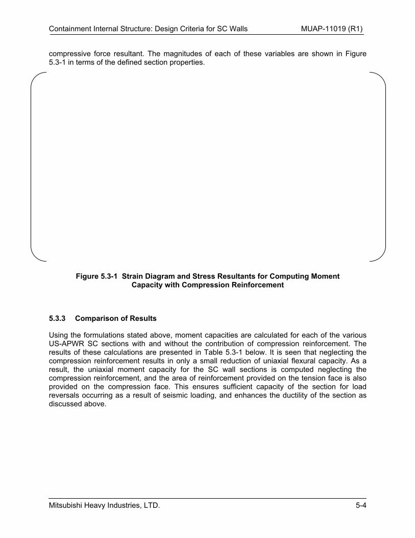
Containment Internal Structure: Design Criteria for SC Walls MUAP-11019 (R1)
Mitsubishi Heavy Industries, LTD. 5-4
compressive force resultant. The magnitudes of each of these variables are shown in Figure 5.3-1 in terms of the defined section properties.
Figure 5.3-1 Strain Diagram and Stress Resultants for Computing Moment Capacity with Compression Reinforcement
5.3.3 Comparison of Results
Using the formulations stated above, moment capacities are calculated for each of the various US-APWR SC sections with and without the contribution of compression reinforcement. The results of these calculations are presented in Table 5.3-1 below. It is seen that neglecting the compression reinforcement results in only a small reduction of uniaxial flexural capacity. As a result, the uniaxial moment capacity for the SC wall sections is computed neglecting the compression reinforcement, and the area of reinforcement provided on the tension face is also provided on the compression face. This ensures sufficient capacity of the section for load reversals occurring as a result of seismic loading, and enhances the ductility of the section as discussed above.
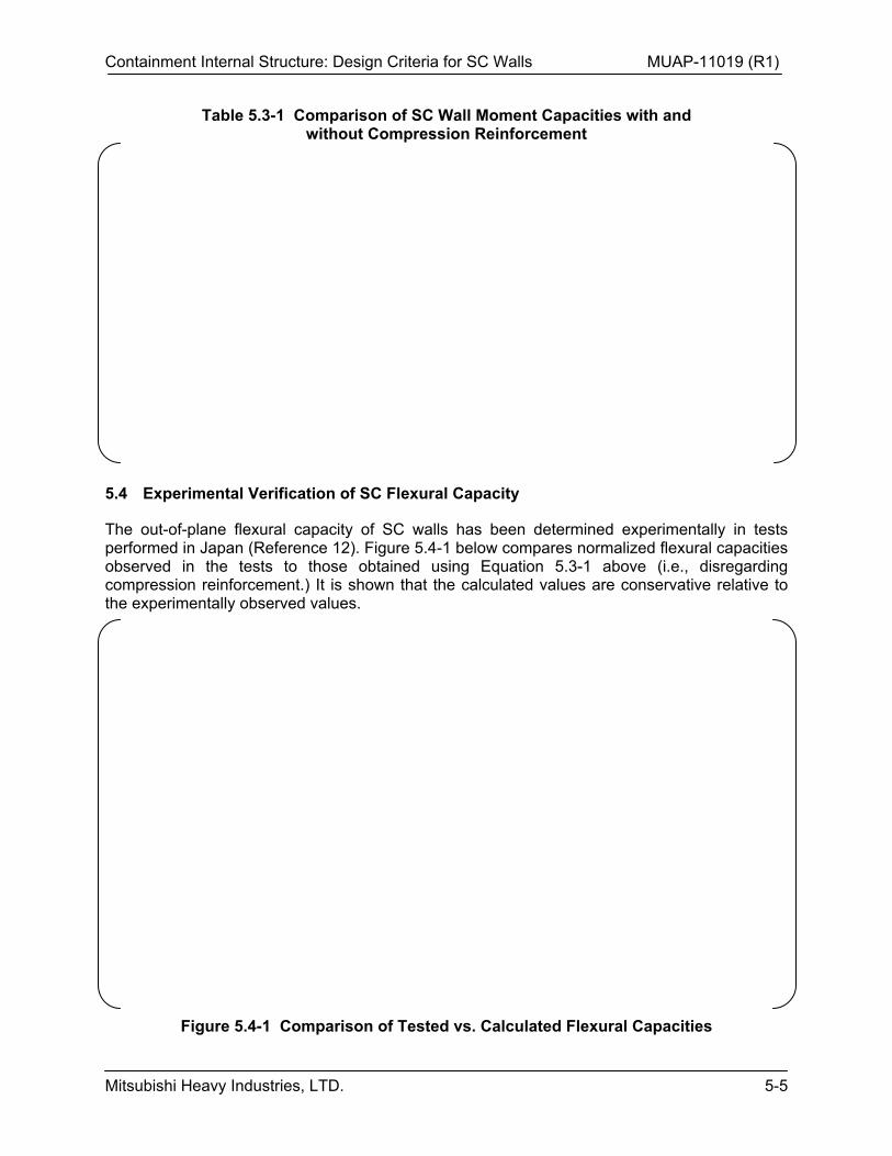
Containment Internal Structure: Design Criteria for SC Walls MUAP-11019 (R1)
Mitsubishi Heavy Industries, LTD. 5-5
Table 5.3-1 Comparison of SC Wall Moment Capacities with and without Compression Reinforcement
5.4 Experimental Verification of SC Flexural Capacity
The out-of-plane flexural capacity of SC walls has been determined experimentally in tests performed in Japan (Reference 12). Figure 5.4-1 below compares normalized flexural capacities observed in the tests to those obtained using Equation 5.3-1 above (i.e., disregarding compression reinforcement.) It is shown that the calculated values are conservative relative to the experimentally observed values.
Figure 5.4-1 Comparison of Tested vs. Calculated Flexural Capacities
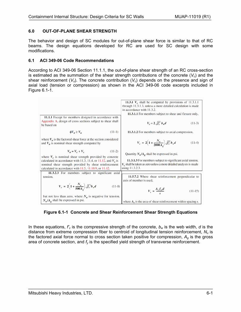
Containment Internal Structure: Design Criteria for SC Walls MUAP-11019 (R1)
Mitsubishi Heavy Industries, LTD. 6-1
6.0 OUT-OF-PLANE SHEAR STRENGTH
The behavior and design of SC modules for out-of-plane shear force is similar to that of RC beams. The design equations developed for RC are used for SC design with some modifications.
6.1 ACI 349-06 Code Recommendations
According to ACI 349-06 Section 11.1.1, the out-of-plane shear strength of an RC cross-section is estimated as the summation of the shear strength contributions of the concrete (Vc) and the shear reinforcement (Vs). The concrete contribution (Vc) depends on the presence and sign of axial load (tension or compression) as shown in the ACI 349-06 code excerpts included in Figure 6.1-1.
Figure 6.1-1 Concrete and Shear Reinforcement Shear Strength Equations
In these equations, f’c is the compressive strength of the concrete, bw is the web width, d is the distance from extreme compression fiber to centroid of longitudinal tension reinforcement, Nu is the factored axial force normal to cross section taken positive for compression, Ag is the gross area of concrete section, and fy is the specified yield strength of transverse reinforcement.
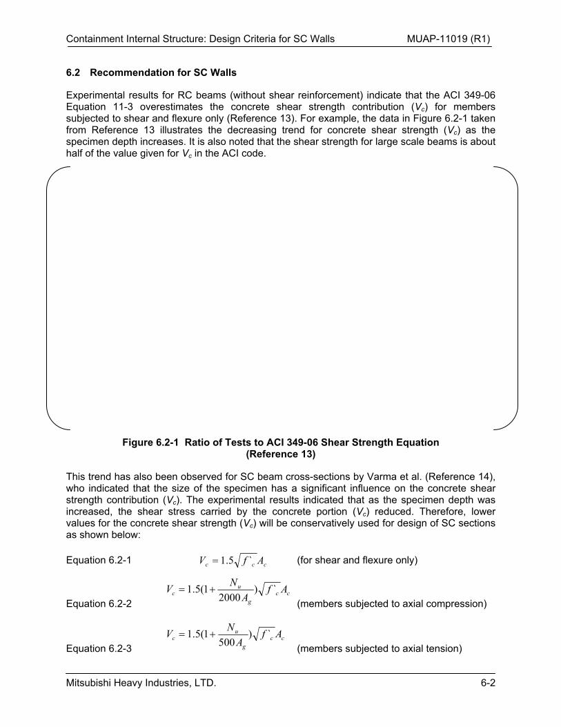
Containment Internal Structure: Design Criteria for SC Walls MUAP-11019 (R1)
Mitsubishi Heavy Industries, LTD. 6-2
6.2 Recommendation for SC Walls
Experimental results for RC beams (without shear reinforcement) indicate that the ACI 349-06 Equation 11-3 overestimates the concrete shear strength contribution (Vc) for members subjected to shear and flexure only (Reference 13). For example, the data in Figure 6.2-1 taken from Reference 13 illustrates the decreasing trend for concrete shear strength (Vc) as the specimen depth increases. It is also noted that the shear strength for large scale beams is about half of the value given for Vc in the ACI code.
Figure 6.2-1 Ratio of Tests to ACI 349-06 Shear Strength Equation (Reference 13)
This trend has also been observed for SC beam cross-sections by Varma et al. (Reference 14), who indicated that the size of the specimen has a significant influence on the concrete shear strength contribution (Vc). The experimental results indicated that as the specimen depth was increased, the shear stress carried by the concrete portion (Vc) reduced. Therefore, lower values for the concrete shear strength (Vc) will be conservatively used for design of SC sections as shown below:
Equation 6.2-1 ccc AfV `5.1
(for shear and flexure only)
Equation 6.2-2 cc
g
uc Af
A
NV `)
20001(5.1
(members subjected to axial compression)
Equation 6.2-3 cc
g
uc Af
A
NV `)
5001(5.1
(members subjected to axial tension)
Containment Internal Structure: Design Criteria for SC Walls MUAP-11019 (R1)
Mitsubishi Heavy Industries, LTD. 6-3
Per ACI 349-06, Nu in Equations 6.2-2 and 6.2-3 is positive for axial compression and negative for axial tension, and the quantity Nu/Ag is expressed in units of pounds per square inch. Vc computed in accordance with Equation 6.2-3 is not taken less than zero.
The contribution of the shear reinforcement (Vs) to the total shear strength is evaluated based on Equation 11-15 given in ACI 349-06 as,
Equation 6.2-4 s
dfAV yv
s
where Av is the area of transverse reinforcement within spacing s and fy is the specified yield strength of reinforcement and d is the total section depth.
6.3 Verification Using Experimental Data
Figure 6.2-1 demonstrates the conservatism of Equation 6.2-1 when used with the ACI 349-06 strength reduction factor for shear (0.85). As seen the equation is a lower bound when compared with the test database that includes several RC beams without shear reinforcement tested in the past.
The proposed equations for shear strength have been compared with tests performed by Takeuchi et al. (Reference 12) and Varma et al. (Reference 14) in Figure 6.3-1. The beams Takeuchi tested, S4 and S6, had 3.6% longitudinal reinforcement ratio, stud spacing-to-faceplate thickness ratio equal to 27.8, shear span to depth ratio equal to 2.6 and section depth of 19.7 in. The specimen had shear reinforcement in the form of 50 ksi yield strength tie bars, and their contribution to the shear strength (Vs) was calculated using Equation 6.2-4. However, the specimen depths were less than half of the section thicknesses used typically for the US-APWR SC walls, such that the influence of section depth on the concrete shear strength contribution (Vc) was not clearly demonstrated.
The beam tested by Varma et al. (Reference 14) was large-scale in terms of the current application sizes, having 2.8% longitudinal reinforcement ratio, stud spacing to faceplate thickness ratio equal to 20, shear span to depth ratio equal to 3.5 and specimen depth equal to 36 in. This beam did not have any shear reinforcement, such that the Vs contribution is equal to zero. Figure 6.3-1 shows the comparisons of the shear strength values measured experimentally and those calculated using the proposed equations. As seen in the Figure, the equations underestimate the shear strength for the Takeuchi beams due to their shallow depth (19.7 in.), but provide a conservative lower bound shear strength in general.
Containment Internal Structure: Design Criteria for SC Walls MUAP-11019 (R1)
Mitsubishi Heavy Industries, LTD. 6-4
Figure 6.3-1 Comparison of Tested vs. Calculated Shear Strength
6.4 Shear Strength Contribution (Vs) of Tie Bars
As stated in ACI 349-06 Section 11.3.1.3 (excerpt shown in Figure 6.1-1), in the presence of significant axial tension (greater than 500 psi on the gross section area or 288 kip/ft. on a 4 ft. thick section) the out-of-plane shear strength is calculated by considering the contribution of the shear reinforcement (Vs) alone and neglecting the contribution (Vc) of the concrete. For simplicity and conservatism, this approach is automatically applied when checking the US-APWR SC wall out-of-plane shear strength for load cases involving seismic loading.
According to Section 11.5.7.2 of ACI 349-06 (excerpt shown in Figure 6.1-1), the contribution of the tie bars (Vs) to the shear strength of a unit foot wide section having [ ] is computed using Equation 11-15 in ACI 349-06 as:
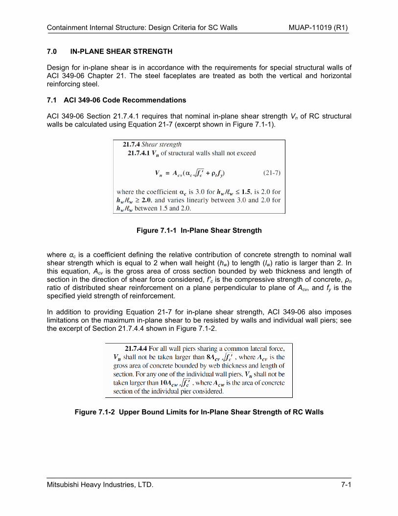
Containment Internal Structure: Design Criteria for SC Walls MUAP-11019 (R1)
Mitsubishi Heavy Industries, LTD. 7-1
7.0 IN-PLANE SHEAR STRENGTH
Design for in-plane shear is in accordance with the requirements for special structural walls of ACI 349-06 Chapter 21. The steel faceplates are treated as both the vertical and horizontal reinforcing steel.
7.1 ACI 349-06 Code Recommendations
ACI 349-06 Section 21.7.4.1 requires that nominal in-plane shear strength Vn of RC structural walls be calculated using Equation 21-7 (excerpt shown in Figure 7.1-1).
Figure 7.1-1 In-Plane Shear Strength
where αc is a coefficient defining the relative contribution of concrete strength to nominal wall shear strength which is equal to 2 when wall height (hw) to length (lw) ratio is larger than 2. In this equation, Acv is the gross area of cross section bounded by web thickness and length of section in the direction of shear force considered, f’c is the compressive strength of concrete, ρn ratio of distributed shear reinforcement on a plane perpendicular to plane of Acv, and fy is the specified yield strength of reinforcement.
In addition to providing Equation 21-7 for in-plane shear strength, ACI 349-06 also imposes limitations on the maximum in-plane shear to be resisted by walls and individual wall piers; see the excerpt of Section 21.7.4.4 shown in Figure 7.1-2.
Figure 7.1-2 Upper Bound Limits for In-Plane Shear Strength of RC Walls
Containment Internal Structure: Design Criteria for SC Walls MUAP-11019 (R1)
Mitsubishi Heavy Industries, LTD. 7-2
7.2 Experimental Data for In-Plane Shear Strength of SC Walls
In-plane shear loading produces principal tension and compression forces in the composite SC section. The principal tension causes cracking in concrete that significantly decreases the concrete contribution to the overall in-plane shear strength and stiffness. Ozaki et al. (Reference 11) have conducted several in-plane shear tests on SC walls to determine the fundamental behavior and cyclic performance. The tests included pure in-plane shear loading and slight axial compression combined with in-plane loading.
The specimens had reinforcement ratios (ρs) ranging from 2.3% to 4.5%, but kept a constant shear stud spacing to faceplate thickness ratio (b/ts) of 30 by adjusting the spacing. The experimental results indicated that as the steel faceplate thickness was increased, the yield strength and the maximum strength increased. In addition it was found that the addition of nominal axial load (200-400 psi compressive stress) did not have a significant effect on the maximum strength.
Figure 7.2-1 Experimental Results from Ozaki Tests, and Comparison with Equation 7.3-1
The specimens were subjected to cyclic shear strain history and maximum in-plane shear forces obtained from the tests. In Figure 7.2-1, maximum in-plane shear forces obtained from the Ozaki tests are compared numerically with the steel faceplate uniaxial yield strengths (AsFy, see Equation 7.3-1). The specimens were subjected to cyclic shear strain history, and maximum in-plane shear forces were obtained from the tests. It is seen that the specimens numerically exhibited maximum in-plane forces comparable to tension strength of the steel faceplates.
Another in-plane test was performed by Sasaki et al. (Reference 15) where seven flanged shear wall specimens were tested under in-plane lateral loading conditions. Of those, five specimens had a height of 1660 mm, one had a height of 1250 mm, and one had a height of 2500 mm. Web SC panel thicknesses were 115 mm, 230 mm, and 345 mm. The steel faceplate thicknesses were constant for all specimens and were equal to 2.3 mm. The corresponding steel reinforcement ratios were 1.33%, 2%, and 4%, which are comparable to the ratios used in
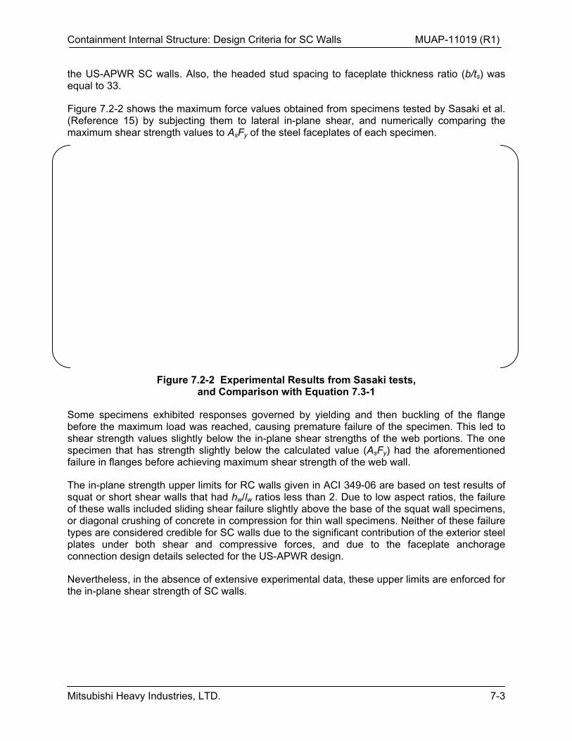
Containment Internal Structure: Design Criteria for SC Walls MUAP-11019 (R1)
Mitsubishi Heavy Industries, LTD. 7-3
the US-APWR SC walls. Also, the headed stud spacing to faceplate thickness ratio (b/ts) was equal to 33.
Figure 7.2-2 shows the maximum force values obtained from specimens tested by Sasaki et al. (Reference 15) by subjecting them to lateral in-plane shear, and numerically comparing the maximum shear strength values to AsFy of the steel faceplates of each specimen.
Figure 7.2-2 Experimental Results from Sasaki tests, and Comparison with Equation 7.3-1
Some specimens exhibited responses governed by yielding and then buckling of the flange before the maximum load was reached, causing premature failure of the specimen. This led to shear strength values slightly below the in-plane shear strengths of the web portions. The one specimen that has strength slightly below the calculated value (AsFy) had the aforementioned failure in flanges before achieving maximum shear strength of the web wall.
The in-plane strength upper limits for RC walls given in ACI 349-06 are based on test results of squat or short shear walls that had hw/lw ratios less than 2. Due to low aspect ratios, the failure of these walls included sliding shear failure slightly above the base of the squat wall specimens, or diagonal crushing of concrete in compression for thin wall specimens. Neither of these failure types are considered credible for SC walls due to the significant contribution of the exterior steel plates under both shear and compressive forces, and due to the faceplate anchorage connection design details selected for the US-APWR design.
Nevertheless, in the absence of extensive experimental data, these upper limits are enforced for the in-plane shear strength of SC walls.
Containment Internal Structure: Design Criteria for SC Walls MUAP-11019 (R1)
Mitsubishi Heavy Industries, LTD. 7-4
7.3 Conservative Equation for In-plane Shear Strength
Based on the test results obtained from Ozaki et al. (Reference 11) and Sasaki et al. (Reference 15) the nominal in-plane shear strength of SC walls is calculated using the following equation:
Equation 7.3-1 ysn fAV
where the original ACI 349-06 Equation 21-7 is modified by conservatively neglecting the concrete contribution (Acv c f’c
0.5).
In the above equation, As is the area of the steel plates (As=Acv t) in the composite section and fy is the specified yield strength for the steel plates. The in-plane shear strengths calculated using the above equation and the experimental results reported by both Ozaki et al. (Reference 11) and Sasaki et al. (Reference 15) are compared in Figure 7.2-1 and Figure 7.2-2. These figures indicate acceptable comparison between the experimental results and the in-plane shear strength calculated using Equation 7.3-1.
The strength reduction factor () of 0.85 further improves the comparison and ensures the conservatism of the in-plane shear strength calculated using Equation 7.3-1. The SC wall design strength equation for in-plane shear is given as follows:
Equation 7.3-2 ysn fAV
The upper bound for the in-plane shear strength of SC walls is limited to
Equation 7.3-3 ccvn fAV '10
This is a conservative limitation for SC design since the failure modes that are the basis for this requirement, including excessive crack widths and localized concrete crushing, are more critical to RC walls.
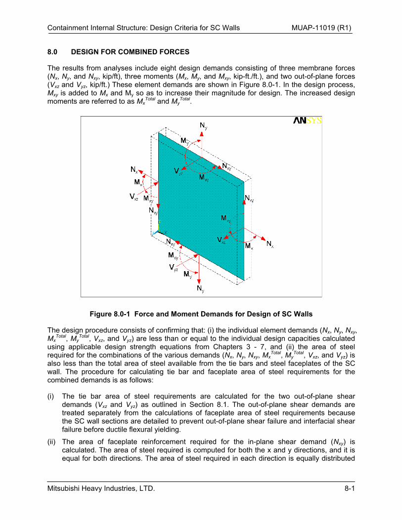
Containment Internal Structure: Design Criteria for SC Walls MUAP-11019 (R1)
Mitsubishi Heavy Industries, LTD. 8-1
8.0 DESIGN FOR COMBINED FORCES
The results from analyses include eight design demands consisting of three membrane forces (Nx, Ny, and Nxy, kip/ft), three moments (Mx, My, and Mxy, kip-ft./ft.), and two out-of-plane forces (Vxz and Vyz, kip/ft.) These element demands are shown in Figure 8.0-1. In the design process, Mxy is added to Mx and My so as to increase their magnitude for design. The increased design moments are referred to as Mx
Total and MyTotal.
Figure 8.0-1 Force and Moment Demands for Design of SC Walls
The design procedure consists of confirming that: (i) the individual element demands (Nx, Ny, Nxy, Mx
Total, MyTotal, Vxz, and Vyz) are less than or equal to the individual design capacities calculated
using applicable design strength equations from Chapters 3 - 7, and (ii) the area of steel required for the combinations of the various demands (Nx, Ny, Nxy, Mx
Total, MyTotal, Vxz, and Vyz) is
also less than the total area of steel available from the tie bars and steel faceplates of the SC wall. The procedure for calculating tie bar and faceplate area of steel requirements for the combined demands is as follows:
(i) The tie bar area of steel requirements are calculated for the two out-of-plane shear demands (Vxz and Vyz) as outlined in Section 8.1. The out-of-plane shear demands are treated separately from the calculations of faceplate area of steel requirements because the SC wall sections are detailed to prevent out-of-plane shear failure and interfacial shear failure before ductile flexural yielding.
(ii) The area of faceplate reinforcement required for the in-plane shear demand (Nxy) is calculated. The area of steel required is computed for both the x and y directions, and it is equal for both directions. The area of steel required in each direction is equally distributed
Containment Internal Structure: Design Criteria for SC Walls MUAP-11019 (R1)
Mitsubishi Heavy Industries, LTD. 8-2
on both faces of the SC wall. The contribution of the concrete infill to the in-plane shear strength is not included.
(iii) To evaluate the combination of axial forces and moments, section analysis is used to identify the balance point where the combination of axial force (Nbal) and out-of-plane moment (M) causes simultaneous: (a) steel faceplate yielding in tension, and (b) concrete compression strain of 0.003.
(iv) When the applied axial force is tensile, or compressive but less than Nbal, then the contribution of the steel compression reinforcement to the flexural resistance is ignored.
(v) When the applied axial force in compression is greater than Nbal, then the contribution of the steel compression reinforcement to the flexural resistance is considered, but the contribution of the steel tension reinforcement to the flexural resistance is ignored.
(vi) If N is less than Nbal, then N and Mtotal are used to compute the area of steel required. If N is tensile, then the area of steel required for N is distributed equally on both faces. The area of steel required for Mtotal is calculated assuming no contribution from the compression reinforcement, but the calculated area is added to both faces (tensile and compressive).
(vii) If N is greater than Nbal, then N and Mtotal are used to compute the area of steel required. The required compression reinforcement is given a negative sign to distinguish it from required tension reinforcement. The area of steel required for Mtotal is calculated assuming no contribution from the reinforcement in tension, but the calculated area is added to both faces (tensile and compressive).
The total area of steel required is computed on both faces and in both directions (Axreq & Ay
req), and compared with the area of steel available on each face in both directions (Ax
avail & Ayavail) as
follows:
(i) If the membrane axial force (Nx or Ny) is tensile, then the procedures of Section 8.4 apply.
(ii) If the membrane axial force (Nx or Ny) is compressive, but the axial compression is less than Nbal, then the procedures of Section 8.5 apply.
(iii) If the membrane axial force (Nx or Ny) is compressive and greater than Nbal, then the procedures of Section 8.6 apply.
Containment Internal Structure: Design Criteria for SC Walls MUAP-11019 (R1)
Mitsubishi Heavy Industries, LTD. 8-3
8.1 Design for Out-of-Plane Shear Demands
The shear reinforcement provided by the tie bars (Vs) resists both the out-of-plane force demands Vxz and Vyz. The required shear reinforcement for both Vxz and Vyz is calculated by subtracting the corresponding concrete shear strength contribution (Vc), and dividing by the yield stress of the shear reinforcement (fyt, equal to [ ] for the US-APWR tie bar design).
Equation 8.1-1 Av1req = (Vxz –vVc)/vfyt ≥ 0
Equation 8.1-2 Av2req = (Vyz – vVc)/vfyt ≥ 0
where Av and vVc are calculated using equations 6.2-1 through 6.2-4. As discussed previously in Section 6.4, the concrete contribution to out-of-plane shear strength (Vc) is conservatively taken equal to zero for all load combinations involving seismic loading.
The provided shear reinforcement Avavail must be greater than or equal to Av
req = Av1req + Av2
req.
Containment Internal Structure: Design Criteria for SC Walls MUAP-11019 (R1)
Mitsubishi Heavy Industries, LTD. 8-4
8.2 Balance Point and Axial Force for SC Wall Cross-Section
The balance point for the SC wall cross-section corresponds to the combination of axial force (Nbal) and moment (M) that causes simultaneous: (a) steel yielding in tension, and (b) concrete compression strain of 0.003. The balance point for the SC wall cross-section and the corresponding axial force (Nbal) are calculated using the stress state shown in Figure 8.2-1.
When the membrane axial force demand (N) is less than Nbal, then steel yielding in tension will occur before the concrete reaches compressive strain of 0.003. For such situations, the contribution of the compression reinforcement to the flexural resistance is ignored, and only the required tension reinforcement is calculated for the various demands (N, M, and Nxy) in both x- and y- directions.
When the membrane axial force demand (N) is greater than Nbal, then the concrete will reach compressive strain of 0.003 before steel yielding in tension. Therefore, for such situations, the contribution of the tension reinforcement to the flexural resistance is ignored, and only the required compression reinforcement is calculated for the combined membrane axial force (N) and moment (Mtotal) in both x- and y- directions.
It is important to note that when the axial compression is high, the concrete infill contributes significantly to the in-plane shear strength and the out-of-plane shear strength of the composite cross-section. However, this contribution and increase in the in-plane and out-of-plane shear strength of the SC section is not included in this conservative design approach.
Containment Internal Structure: Design Criteria for SC Walls MUAP-11019 (R1)
Mitsubishi Heavy Industries, LTD. 8-5
Figure 8.2-1 Balanced Strain State for SC Walls
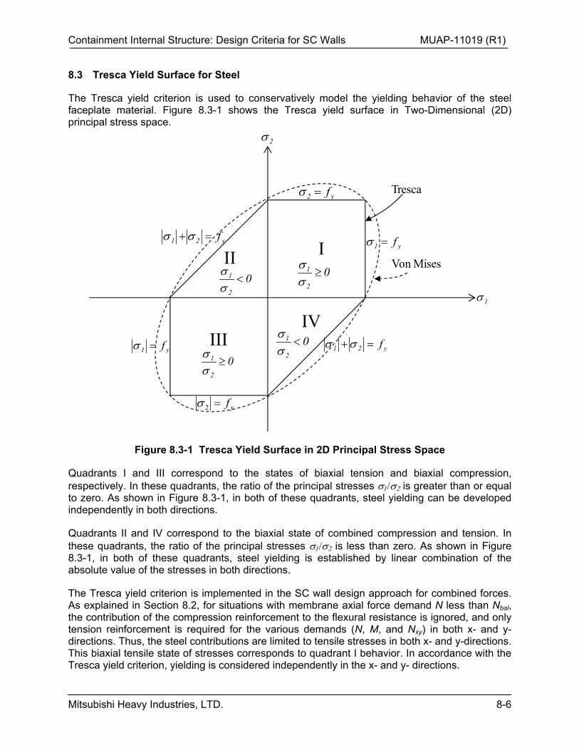
Containment Internal Structure: Design Criteria for SC Walls MUAP-11019 (R1)
Mitsubishi Heavy Industries, LTD. 8-6
8.3 Tresca Yield Surface for Steel
The Tresca yield criterion is used to conservatively model the yielding behavior of the steel faceplate material. Figure 8.3-1 shows the Tresca yield surface in Two-Dimensional (2D) principal stress space.
Figure 8.3-1 Tresca Yield Surface in 2D Principal Stress Space
Quadrants I and III correspond to the states of biaxial tension and biaxial compression, respectively. In these quadrants, the ratio of the principal stresses is greater than or equal to zero. As shown in Figure 8.3-1, in both of these quadrants, steel yielding can be developed independently in both directions.
Quadrants II and IV correspond to the biaxial state of combined compression and tension. In these quadrants, the ratio of the principal stresses is less than zero. As shown in Figure 8.3-1, in both of these quadrants, steel yielding is established by linear combination of the absolute value of the stresses in both directions.
The Tresca yield criterion is implemented in the SC wall design approach for combined forces. As explained in Section 8.2, for situations with membrane axial force demand N less than Nbal, the contribution of the compression reinforcement to the flexural resistance is ignored, and only tension reinforcement is required for the various demands (N, M, and Nxy) in both x- and y- directions. Thus, the steel contributions are limited to tensile stresses in both x- and y-directions. This biaxial tensile state of stresses corresponds to quadrant I behavior. In accordance with the Tresca yield criterion, yielding is considered independently in the x- and y- directions.
II I
IVIII
1
2
y1 f
y2 f
y1 f
yf2
y21 f
y21 f
Tresca
Von Mises0
2
1
02
1
02
1
02
1
Containment Internal Structure: Design Criteria for SC Walls MUAP-11019 (R1)
Mitsubishi Heavy Industries, LTD. 8-7
As explained in Section 8.2, for situations with membrane axial force demand N greater than Nbal, the contribution of the tension reinforcement to the flexural resistance is ignored, and only the required compression reinforcement is calculated for the N and M demands in both x- and y-directions. The tension reinforcement required for Nxy is also calculated in both x- and y- directions. This biaxial state of combined compressive and tensile stresses corresponds to quadrant II, III, or IV behavior. If it corresponds to quadrant III, then yielding is considered independently in the x- and y-directions. If it corresponds to quadrants II or IV, then yielding is considered by linear combination of the absolute values of the stresses in both directions. 8.4 Design for Combined Axial Tension, Flexure, and In-Plane Shear
If the membrane force Nx or Ny is tensile, then the concrete is assumed to be fully cracked. The area of steel required on each face to resist Nx, Mx
total, and Nxy, or Ny, Mytotal, and Nxy is computed
as shown in Equations 8.4-1 to 8.4-4 given in Table 8.4-1.
Table 8.4-1 Design for Combined Forces with Nx or Ny in Tension
In these Equations, AxTreq and AyT
req are the areas of steel required on each face to resist Nx and Ny, respectively calculated using Equation 8.4-1. AxF
req and AyFreq are the areas of steel required
on each face to resist Mxtotal and My
total, respectively, calculated using Equation 8.4-2. Equation 8.4-1 and Equation 8.4-2 were obtained by considering the stress block diagrams shown in Figure 8.4-1. As shown in the Figure, the contribution of the steel in compression to the flexural capacity is not included. AxV
req and AyVreq are the areas of tension steel required on each face to
resist Nxy, calculated using Equation 8.4-3.
As shown in Equation 8.4-4, the total area of steel available on each face in the x and y directions (Ax
avail and Ayavail) must be greater than the corresponding required values (Ax
req and Ay
req), which are the sum of steel areas required for tension, flexure, and in-plane shear. This is in accordance with Section 8.3.
Containment Internal Structure: Design Criteria for SC Walls MUAP-11019 (R1)
Mitsubishi Heavy Industries, LTD. 8-8
Figure 8.4-1 Section Equilibrium Used to Compute Steel Areas when Nx, Ny in Tension
Containment Internal Structure: Design Criteria for SC Walls MUAP-11019 (R1)
Mitsubishi Heavy Industries, LTD. 8-9
8.5 Design for Combined Axial Compression (N< Nbal), Flexure, and In-Plane Shear
If the membrane force Nx or Ny is compressive but less than Nbal, then the concrete will have greater contribution to resisting the moments (Mx or My) and the in-plane shear (Nxy). The area of steel required on each face to resist Nx + Mx
total and Nxy, or Ny + Mytotal and Nxy, is computed as
shown in Equation 8.5-1 to Equation 8.5-4 given in Table 8.5-1.
Table 8.5-1 Design for Combined Forces with Nx or Ny in Compression
In these Equations, AxF
req and AyFreq are the areas of steel required on each face to resist Nx +
Mxtotal and Ny + My
total, respectively, calculated using Equation 8.5-1. In this Equation, Mcx and Mcy are the contributions of the concrete to the moment capacity, which are calculated using Equation 8.5-2.
Equation 8.5-1 and Equation 8.5-2 were obtained by considering the stress block diagrams shown in Figure 8.5-1. As shown in the Figure, the contribution of the steel in compression is not included for conservatism.
AxVreq and AyV
req are the areas of tension steel required on each face to resist Nxy, calculated using Equation 8.5-3.
As shown in Equation 8.5-4, the total area of steel available on each face in the x and y directions (Ax
avail and Ayavail) must be greater than the corresponding required values (Ax
req and Ay
req), which are the sum of steel areas required for compression + flexure, and in-plane shear. This is in accordance with Section 8.3.
Containment Internal Structure: Design Criteria for SC Walls MUAP-11019 (R1)
Mitsubishi Heavy Industries, LTD. 8-10
Figure 8.5-1 Section Equilibrium Used to Compute Steel Areas when Nx, Ny in Compression
Containment Internal Structure: Design Criteria for SC Walls MUAP-11019 (R1)
Mitsubishi Heavy Industries, LTD. 8-11
8.6 Design for High Axial Compression (N> Nbal), Flexure, and In-Plane Shear
If the membrane axial compression demand is greater than Nbal, then the area of steel required on each face to resist Nx + Mx
total and Nxy, or Ny + Mytotal and Nxy is computed as shown using
Equations 8.6-1 to 8.6-5 in Table 8.6-1.
Table 8.6-1 Design for Combined Forces with High Compression in Nx or Ny Direction
In these Equations, AxFreq and AyF
req are the areas of steel in compression required to resist Nx + Mx
total and Ny+Mytotal, respectively, calculated using Equation 8.6-1. The calculated areas of steel
required are multiplied by -1 to indicate that these are required steel reinforcement in compression. Mcx and Mcy are the contributions of the concrete to the moment capacity, which are calculated using Equation 8.6-2. In this computation, the absolute values of AxF
req and AyFreq
are used because they were multiplied by -1 in Equation 8.6-1.
Equations 8.6-1 and Equation 8.6-2 were obtained by considering the stress block diagrams shown in Figure 8.6-1. As shown in the Figure, the contribution of the steel in tension is not included for conservatism. However, the calculated areas of steel are provided on both faces for added conservatism.
AxVreq and AyV
req are the areas of tension steel required on each face to resist Nxy, calculated using Equation 8.6-3.
As shown in Equation 8.6-4, if the ratio of the areas of steel required in x- and y-directions is greater than or equal to zero, which corresponds to stress states in quadrants I (biaxial tension) and III (biaxial compression), then the total area of steel available on each face in the x- and y-
Containment Internal Structure: Design Criteria for SC Walls MUAP-11019 (R1)
Mitsubishi Heavy Industries, LTD. 8-12
directions (Axavail and Ay
avail) must be greater than the corresponding required values (Axreq and
Ayreq), which are the sum of the absolute steel areas required for compression + flexure and in-
plane shear. This is in accordance with the Tresca criteria for yielding of steel in quadrants I and III as described in Section 8.3.
As shown in Equation 8.6-5, if the ratio of the areas of steel required in x- and y-directions is less than zero, which corresponds to stress states in quadrants II and IV (biaxial compression and tension), then the total area of steel available on each face in the x- and y- directions (Ax
avail and Ay
avail) must be greater than the sum of the absolute steel areas required in both the x- and y-directions for compression + flexure and in-plane shear. This is in accordance with the Tresca criteria for yielding of steel in quadrants II and IV as described in Section 8.3.
Figure 8.6-1 Stress Blocks for SC Walls Subjected to High Compression and Flexure
Containment Internal Structure: Design Criteria for SC Walls MUAP-11019 (R1)
Mitsubishi Heavy Industries, LTD. 8-13
8.7 Limitations on Demand/Capacity Ratios
In the actual design for combined axial, flexural, and in-plane shear forces resisted by the SC walls, the steel faceplate utility ratios calculated as Ax
req/Axavail and Ay
req/Ayavail using the
equations in Sections 8.2 to 8.5 are limited to a maximum of 0.90. Similarly, the steel tie bar utility ratios calculated as Av
req/Avavail are limited to a maximum of 0.90.
These limitations are imposed to provide an additional level of overall conservatism in the SC wall design, while also accounting for secondary effects not directly accounted for in the CIS FE analysis, such as small faceplate and tie bar stresses imparted during concrete casting.
Containment Internal Structure: Design Criteria for SC Walls MUAP-11019 (R1)
Mitsubishi Heavy Industries, LTD. 9-1
9.0 ACCIDENT THERMAL CONSIDERATIONS
The thermal effects of accident thermal conditions (Ta) on the US-APWR CIS has been presented and discussed in detail in TeR MUAP-11018 Rev. 1 (Reference 5). After the first few minutes, accident thermal conditions produce similar temperatures on both the exterior steel faceplates. The temperature of the concrete infill lags behind that of the steel faceplates due to its low thermal conductivity and large thermal inertia. The temperature profiles through the composite cross-section and the temperature-time (T-t) curves for different points within the composite cross-section are computed by conducting one-dimensional heat transfer analysis. The validity of such heat transfer calculations has been demonstrated by Ozaki et al. (Reference 17).
9.1 Effects on Design Force Demands
The results of heat transfer analyses indicate nonlinear (parabolic) temperature profiles through the composite cross-section as shown in Figure 9.1-1. This parabolic temperature profile results in through-section cracking of the concrete infill for all the secondary shield SC walls of the CIS. The occurrence of this through-section cracking has been experimentally observed and discussed by Ozaki et al. (Reference 17) for in-plane conditions, and Varma et al. (Reference 18) for out-of-plane conditions. These researchers have also demonstrated the significant relief in steel faceplate stresses due to the cracking of the concrete infill.
Figure 9.1-1 Calculated Temperature Profiles in 4 ft. Thick Secondary Shield Wall
For these parabolic thermal gradients with similar steel faceplate temperatures on both exterior faces, the steel faceplates will have limited mechanical stresses in the interior portions of SC walls that are away from supports, restraints, and connections. The concrete infill will have
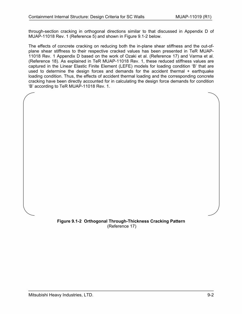
Containment Internal Structure: Design Criteria for SC Walls MUAP-11019 (R1)
Mitsubishi Heavy Industries, LTD. 9-2
through-section cracking in orthogonal directions similar to that discussed in Appendix D of MUAP-11018 Rev. 1 (Reference 5) and shown in Figure 9.1-2 below.
The effects of concrete cracking on reducing both the in-plane shear stiffness and the out-of-plane shear stiffness to their respective cracked values has been presented in TeR MUAP-11018 Rev. 1 Appendix D based on the work of Ozaki et al. (Reference 17) and Varma et al. (Reference 18). As explained in TeR MUAP-11018 Rev. 1, these reduced stiffness values are captured in the Linear Elastic Finite Element (LEFE) models for loading condition ‘B’ that are used to determine the design forces and demands for the accident thermal + earthquake loading condition. Thus, the effects of accident thermal loading and the corresponding concrete cracking have been directly accounted for in calculating the design force demands for condition ‘B’ according to TeR MUAP-11018 Rev. 1.
Figure 9.1-2 Orthogonal Through-Thickness Cracking Pattern (Reference 17)
Containment Internal Structure: Design Criteria for SC Walls MUAP-11019 (R1)
Mitsubishi Heavy Industries, LTD. 9-3
9.2 Effects on Design Capacities
The effects of concrete cracking due to accident thermal loading on the SC wall design capacities calculated according to Sections 3 -8 are as follows:
1) Equation 3.1-1 remains applicable for calculating the axial tension strength, because the concrete infill was assumed to have no influence on the calculated axial tension strength even before cracking induced by the accident thermal condition.
2) Equation 4.1-1 remains applicable for calculating the axial compressive strength. Concrete cracking due to accident thermal loading will cause the compressive force to be resisted by the steel faceplates only before crack closure occurs. This reduction in the section resistance (stiffness) has already been accounted for in calculating the design force demand as described in TeR MUAP-11018 Rev. 1 and Section 9.1. Concrete crack closure will occur if the axial compression demand is high, and the total axial compressive strength will still be equal to that calculated using Equation 4.1-1.
3) Equation 5.3-1 remains applicable for calculating the flexural strength. Concrete cracking due to accident thermal loading will initially cause the compressive force of the moment couple in the cross-section to be resisted by the compressive steel faceplate only before crack closure occurs. However, concrete crack closure will eventually occur as the moment demand (and the corresponding compressive force produced by the moment couple) becomes large. The final moment capacity will be governed by stress state similar to that shown in Figure 5.3-1, and can be calculated conservatively using Equation 5.3-1. The section moment-curvature (M-) behavior after concrete cracking due to accident thermal loading and the moment capacity has been discussed in detail by Varma et al. (Reference 18).
4) Equations 6.2-1 to 6.2-4 remain applicable for calculating out-of-plane shear strength. As shown by Varma et al. (Reference 18), concrete cracking due to accident thermal condition does not seem to have a major influence on the out-of-plane shear strength of SC beams. This is probably because the thermally induced cracks are perpendicular to the steel faceplates. These cracks have to turn by 45-60o to develop out-of-plane shear cracks in the concrete, which probably requires approximately the same amount of force as that required to develop new shear cracks due to the anisotropic cracking nature of concrete. Additionally, the Vs contribution to the out-of-plane shear strength is unchanged because the temperature of the steel shear reinforcement embedded in the concrete is not high enough to change the yield strength etc.
5) Equation 7.3-1 remains applicable for calculating the in-plane shear strength of SC walls. The effects of thermally induced concrete cracking on the in-plane shear behavior and strength of SC walls has been investigated by Ozaki et al. (Reference 17), which was also presented and discussed in TeR MUAP-11018 Rev. 1 Appendix D. As demonstrated by Ozaki et al., thermally induced concrete cracking does not reduce the in-plane shear strength of SC walls, and the ambient equations for in-plane shear strength remain applicable.
6) Since thermally induced concrete cracking has no significant influence on the individual design capacities of SC walls, it is also appropriate to perform the design for combined forces according to the Tables and Equations presented in Sections 8.1 to 8.5.
Containment Internal Structure: Design Criteria for SC Walls MUAP-11019 (R1)
Mitsubishi Heavy Industries, LTD. 9-4
9.3 SC Specific Design Issue – Local Buckling
Testing has been performed in Japan to evaluate the occurrence of steel faceplate local buckling due to applied thermal loading. Sekimoto and Kondo (Reference 19) conducted a series of tests on SC walls subjected to temperature changes of 50 – 500oC in steps of 50 or 100oC. For SC specimens with s/t less than 20, no local buckling of the steel faceplates was observed, both in specimens with and without full restraint. Concrete cracking similar to that discussed in Sections 9.1 and 9.2 above was observed in the specimens.
The accident thermal loading on the US-APWR CIS imparts temperature changes (∆T) in the steel faceplates of the various SC walls that are well within the range of temperatures considered in the Japanese testing. For example, the steel faceplate temperatures of 300oF occurring after the postulated pipe rupture result in a temperature change of approximately 200oF or 93oC, given the winter normal operating temperature of 105oF. Assuming a steel thermal expansion coefficient (s
TH) of 6.5x10⁻⁶ /oF, this corresponds to a thermal expansion strain of 1300 microstrain. If the steel faceplate expansion is fully restrained, which only occurs in the connection regions close to rigid supports or the basemat, the steel faceplate compressive stress would be 37.7 ksi, which is less than the specified yield stress of 50 ksi. As explained earlier in Section 2.1, all the steel faceplates have slenderness (stud spacing/plate thickness) less than 20, which ensures that local buckling will not occur before yielding in compression. Thus, even if the accident thermal expansion is fully restrained, the steel faceplate will not undergo yielding or local buckling.
Containment Internal Structure: Design Criteria for SC Walls MUAP-11019 (R1)
Mitsubishi Heavy Industries, LTD. 10-1
10.0 REFERENCES
1. Mitsubishi Heavy Industries, Ltd., “Containment Internal Structure Design and Validation Methodology,” MUAP-11013, Revision 2, February 2013.
2. American Concrete Institute, “Code Requirements for Nuclear Safety Related Concrete Structures,” ACI 349-06, November 2006.
3. Mitsubishi Heavy Industries, Ltd., “Research Achievements of SC Structure and Strength Evaluation of US-APWR SC Structure Based on 1/10th Scale Test Results,” MUAP-11005, Revision 1, December 2012.
4. Mitsubishi Heavy Industries, Ltd., “Containment Internal Structure: Anchorage and Connection Design and Detailing,” MUAP-11020, Revision 1, February 2013.
5. Mitsubishi Heavy Industries, Ltd., “Containment Internal Structure: Stiffness and Damping for Analysis,” MUAP-11018, Revision 1, February 2013.
6. Varma, A.H., Malushte, S.R., Sener, K.C., Zhang, K., “Steel-Plate Composite (SC) Walls For Safety Related Nuclear Facilities: Part 1- General Design Requirements,” 21st International Conference on Structural Mechanics in Reactor Technology, 2011.
7. American Concrete Institute, “Building Code Requirements for Structural Concrete and Commentary,” ACI 318-05, January 2005.
8. Eligehausen, R., Mallée, R., and Silva, J.A., “Anchorage in Concrete Construction,” Ernst & Sohn, 2006.
9. MacGregor, J.G., “Reinforced Concrete Mechanics and Design,” 3rd Edition, Prentice Hall, 1997.
10. Mitsubishi Heavy Industries, Ltd., “Steel Concrete (SC) Wall Fabrication, Construction, and Inspection,” MUAP-12006, Revision 0, February 2013.
11. Ozaki, M., et al., “Study on Steel Plate Reinforced Concrete Panels Subjected to Cyclic In-Plane Shear,” Nuclear Engineering and Design, Volume 228, 2004.
12. Takeuchi, Masayuki, et al., “Experimental Study on Steel Plate Reinforced Concrete Structure Part 28 Response of SC Members Subjected to Out-of-plane Load (1&2),” Papers 2619 and 2620, Summaries of Technical Papers of Annual Meeting, Architectural Institute of Japan, 1999.
13. Sneed, L. H., and Ramirez, J. A., “Effect of Depth on the Shear Strength of Concrete Beams Without Shear Reinforcement—Experimental Study”, ACI Structural Journal, V. 107, No. 5, September-October 2010.
14. Varma, A.H., Sener, K.C., Zhang, K., Coogler, K. and Malushte, S.R., “Out-of-Plane Shear Behavior of SC Composite Structures,” 21st International Conference on Structural Mechanics in Reactor Technology, 2011.
15. Sasaki, N., Akiyama, H., Narikawa, M., Hara, K., Takeuchi, M., and Usami, S., “Study on A Concrete Filled Steel Structure for Nuclear Power Plants Part 3 Shear and Bending Loading Tests on Wall Member,” 13th International Conference on Structural Mechanics in Reactor Technology, 1995.
16. American Concrete Institute, “Guide to Formwork for Concrete,” ACI 347-04, October 2004.
Containment Internal Structure: Design Criteria for SC Walls MUAP-11019 (R1)
Mitsubishi Heavy Industries, LTD. 10-2
17. Ozaki, M., Akita, S., Takeuchi, M., Oosuga, H., Nakayama, T., and Niwa, H., “Study on Steel Plate Reinforced Concrete Structure Part 41: Heating Tests (Outline of Experimental Program and Results,” Annual Conference of Architectural Institute of Japan, Part 41-43, 2000.
18. Varma, A.H., Malushte, S.R., Sener, K.C., Booth, P., and Coogler, K., “Steel-Plate Composite (SC) Walls: Analysis and Design Including Thermal Effects,” 21st International Conference on Structural Mechanics in Reactor Technology, 2011.
19. Sekimoto, H., and Kondo, M., “Study on Property of Concrete-Filled Steel Bearing Wall Subjected to High Temperature,” Journal of Structural Engineering, Vol 47B, pp. 481-490, 2001.
Containment Internal Structure: Design Criteria for SC Walls MUAP-11019 (R1)
Mitsubishi Heavy Industries, LTD. A1-1
APPENDIX 1
Sample Calculations of
Reinforcement Requirements
Containment Internal Structure: Design Criteria for SC Walls MUAP-11019 (R1)
Mitsubishi Heavy Industries, LTD. A1-2
TABLE OF CONTENTS
A.1-1 Combined Axial Tension, Flexure, and In-Plane Shear ...................................................... A1-3
A.1-2 Combined Axial Compression, Flexure, and In-Plane Shear ............................................. A1-8
Containment Internal Structure: Design Criteria for SC Walls MUAP-11019 (R1)
Mitsubishi Heavy Industries, LTD. A1-3
A.1-1 Evaluate an SC wall element for a set of design demands consisting of Combined Axial Tension, Flexure, and In-Plane Shear, using Chapter 8 procedures.
Containment Internal Structure: Design Criteria for SC Walls MUAP-11019 (R1)
Mitsubishi Heavy Industries, LTD. A1-4
A.1-1, Continued Combined Axial Tension, Flexure, and In-Plane Shear Case.

Containment Internal Structure: Design Criteria for SC Walls MUAP-11019 (R1)
Mitsubishi Heavy Industries, LTD. A1-5
A.1-1, Continued Combined Axial Tension, Flexure, and In-Plane Shear Case.

Containment Internal Structure: Design Criteria for SC Walls MUAP-11019 (R1)
Mitsubishi Heavy Industries, LTD. A1-6
A.1-1, Continued Combined Axial Tension, Flexure, and In-Plane Shear Case.
Containment Internal Structure: Design Criteria for SC Walls MUAP-11019 (R1)
Mitsubishi Heavy Industries, LTD. A1-7
A.1-1, Continued Combined Axial Tension, Flexure, and In-Plane Shear Case.
Containment Internal Structure: Design Criteria for SC Walls MUAP-11019 (R1)
Mitsubishi Heavy Industries, LTD. A1-8
A.1-2 Evaluate an SC wall element for a set of design demands consisting of Combined Axial Compression, Flexure, and In-Plane Shear, using Chapter 8 procedures.
Containment Internal Structure: Design Criteria for SC Walls MUAP-11019 (R1)
Mitsubishi Heavy Industries, LTD. A1-9
A.1-2, Continued Combined Axial Compression, Flexure, and In-Plane Shear Case.
Containment Internal Structure: Design Criteria for SC Walls MUAP-11019 (R1)
Mitsubishi Heavy Industries, LTD. A1-10
A.1-2, Continued Combined Axial Compression, Flexure, and In-Plane Shear Case.
Containment Internal Structure: Design Criteria for SC Walls MUAP-11019 (R1)
Mitsubishi Heavy Industries, LTD. A1-11
A.1-2, Continued Combined Axial Compression, Flexure, and In-Plane Shear Case.
Containment Internal Structure: Design Criteria for SC Walls MUAP-11019 (R1)
Mitsubishi Heavy Industries, LTD. A1-12
A.1-2, Continued Combined Axial Compression, Flexure, and In-Plane Shear Case.
Containment Internal Structure: Design Criteria for SC Walls MUAP-11019 (R1)
Mitsubishi Heavy Industries, LTD. A2-1
APPENDIX 2
Design Criteria for Primary Shield Structure
Containment Internal Structure: Design Criteria for SC Walls MUAP-11019 (R1)
Mitsubishi Heavy Industries, LTD. A2-2
TABLE OF CONTENTS
A.2-1 DESIGN CRITERIA FOR PRIMARY SHIELD STRUCTURE ............................................. A2-3
LIST OF FIGURES
Figure A2-1 Geometry and Multi-Cellular Layout of Primary Shield .............................................. A2-3 Figure A2-2 1/6th Scale Test of Primary Shield Structure .............................................................. A2-5
Containment Internal Structure: Design Criteria for SC Walls MUAP-11019 (R1)
Mitsubishi Heavy Industries, LTD. A2-3
A.2-1 DESIGN CRITERIA FOR PRIMARY SHIELD STRUCTURE
Figure A2-1 Geometry and Multi-Cellular Layout of Primary Shield
Containment Internal Structure: Design Criteria for SC Walls MUAP-11019 (R1)
Mitsubishi Heavy Industries, LTD. A2-4
Containment Internal Structure: Design Criteria for SC Walls MUAP-11019 (R1)
Mitsubishi Heavy Industries, LTD. A2-5
Figure A2-2 1/6th Scale Test of Primary Shield Structure
Containment Internal Structure: Design Criteria for SC Walls MUAP-11019 (R1)
Mitsubishi Heavy Industries, LTD. A2-6
APPENDIX 2 REFERENCES: 1. Mitsubishi Heavy Industries, Ltd., “Containment Internal Structure: Stiffness and Damping for
Analysis,” MUAP-11018, Revision 1, February 2013.
2. American Concrete Institute, “Code Requirements for Nuclear Safety Related Concrete Structures,” ACI 349-06, November 2006.
3. Mitsubishi Heavy Industries, Ltd., “Research Achievements of SC Structure and Strength Evaluation of US-APWR SC Structure Based on 1/10th Scale Test Results,” MUAP-11005, Revision 1, December 2012.
4. American Institute of Steel Construction, “Specification for the Design, Fabrication and Erection of Steel Safety-Related Structures for Nuclear Facilities,” including Supplement 2 (2004), ANSI/AISC N690-1994, 1994 & 2004.