Embed Size (px)
Citation preview
Section
Selection Guide
.....................................D-3
Non-Reversing Contactors
• YS1N AC Controlled . . . . . . . . . . .D-5• YS3N DC Controlled . . . . . . . . . . .D-6
Reversing Contactors
• YS1R AC Controlled . . . . . . . . . . .D-7• YS3R DC Controlled . . . . . . . . . . .D-8
Thermal Overload Relay
• YS1T-RHA. . . . . . . . . . . . . . . . . . .D-9
Starters.............................................D-11
Accessories .......................................D-12
Specifications
• Contactors and Starters . . . . . . . .D-16• Overload Relays . . . . . . . . . . . . . .D-24• Accessories. . . . . . . . . . . . . . . . . .D-28
Dimensions.......................................D-35
Mounting Diagrams........................D-43
Wiring Diagrams.............................D-47
Application Tables...........................D-51
D
IEC Contactors
ww
w.idec.com
/contactor
for more information on this product family visit
www.idec.com/contactor
Additional Web Resources
• New and updated product information • Downloadable software demos & upgrades • Part configuration tool & cross reference • Online stock check & ordering • IDEC field sales & distributor search • Online literature request • Downloadable manuals & CAD drawings • Manufacturer’s suggested retail price list • Product training schedule & locations • Advertising & trade show schedules • Press releases & FAQs
Courtesy of Steven Engineering, Inc.-230 Ryan Way, South San Francisco, CA 94080-6370-Main Office: (650) 588-9200-Outside Local Area: (800) 258-9200-www.stevenengineering.com
Selection Guide
IEC Contactors
D-2
www.idec.com
USA: (800) 262-IDEC or (408) 747-0550, Canada: (888) 317-IDEC
D
IE
C C
on
tacto
rs
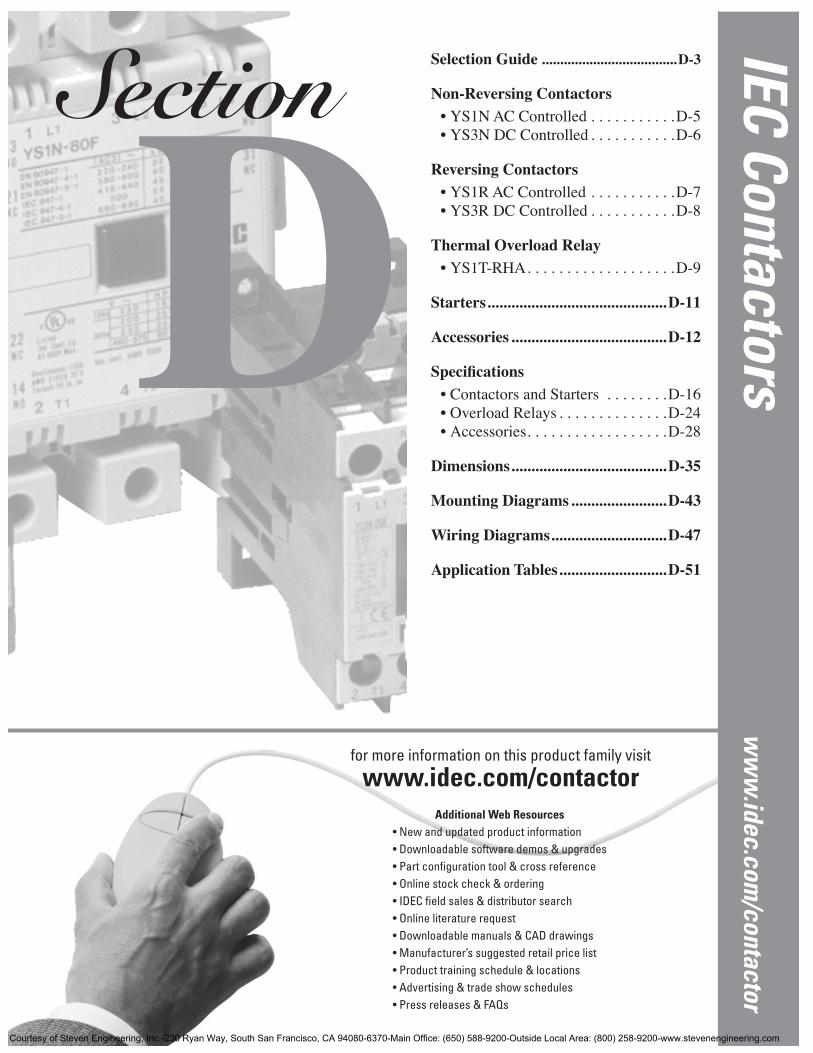
YS Series: Superior performance and low maintenance
IDEC YS Series Contactors / Starters
Key features include:• Simple, compact, rugged electromechanical devices• Meets IEC, UL, c-UL and other international standards• All Contactors, Thermal Overload Relays, and Auxiliary Contact Blocks
bear the CE mark• 35mm or 75mm DIN Rail or direct panel mounting• Bifurcated double bridge auxiliary contacts, the moving contact bridge
has an “H” form; suitable for interface with electronic circuit• Advanced design and materials, special silver-alloy long life contacts• Cadmium-free contacts for environmental safety• Bimetallic thermal overload relays• Easy operation and maintenance; Direct and simple motor control• Dual frequency 50/60 Hz coils
IDEC YS Series Contactors are used in switching motor loads. Like allIDEC products, each model is engineered for long life, minimum mainte-nance, dependable operation, and superior performance.
Snap on accessories are available for the IDEC YS series, giving eachmodel the flexibility to meet any application requirement.
1. Auxiliary contact blocks • Top mounting type (2 or 4 poles type)• Side mounting type (2 poles type)
2. Adjustable thermal overloads3. Surge suppressor modules 4. Mechanical interlock blocks5. PLC interface modules
Courtesy of Steven Engineering, Inc.-230 Ryan Way, South San Francisco, CA 94080-6370-Main Office: (650) 588-9200-Outside Local Area: (800) 258-9200-www.stevenengineering.com
IEC Contactors
Selection Guide
www.idec.com
USA: (800) 262-IDEC or (408) 747-0550, Canada: (888) 317-IDEC D-3
D
IEC
Co
nta
cto
rs
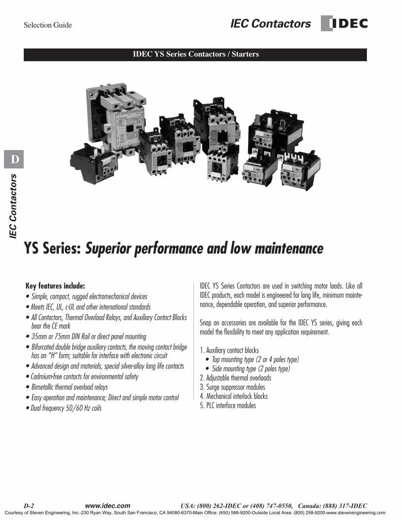
SURGE SUPPRESSOR MODULES
YS9Z-TU25 for YS1N-9F to -25FYS9Z-TU65 for YS1N-32F to -65F YS9Z-TU125 for YS1N-80F to -125FYS9Z-TU180 for YS1N-150F to -180FYS9Z-TU300 for YS1N-220F to -300F
AUX. CONTACT BLOCK
(2P, side mounting type)YS1A-TAS211F for YS1N-9F to -65F
AUX. CONTACT BLOCKS
(2P, top mounting type)YS1A-TAH220F (2NO)YS1A-TAH211F (1NO-1NC)YS1A-TAH202F (2NC)for YS1N-9F to -65F
AUX. CONTACT BLOCKS
(4P, top mounting type)YS1A-TAH440F (4NO)YS1A-TAH431F (3NO-1NC)YS1A-TAH422F (2NO-2NC)YS1A-TAH413F (1NO-3NC)YS1A-TAH404F (4NC)for YS1N-9F to -65F
MECHANICALINTERLOCK BLOCKS
RELAY INTERFACE MODULE
(With Surge Suppressor Module)YS9Z-TCU500UH
The interface module incorporates con-tacts which are actuated upon energiza-tion of the module from low power 24VDC sources such as outputs from sensors and programmable controllers.
CONTACTORS
Non-reversingYS1N, AC ControlledYS3N, DC Controlled
SECONDCONTACTOR
For reversing applicationsYS1R, AC ControlledYS3R, DC Controlled(reversing type)
Used for reversing contactorsYS9Z-TMI65 for YS1N-9F through 65FYS9Z-TMI125 for YS1N-80F through 300F
Selection Guide
Courtesy of Steven Engineering, Inc.-230 Ryan Way, South San Francisco, CA 94080-6370-Main Office: (650) 588-9200-Outside Local Area: (800) 258-9200-www.stevenengineering.com
YS Series
IEC Contactors
D-4
www.idec.com
USA: (800) 262-IDEC or (408) 747-0550, Canada: (888) 317-IDEC
D
IE
C C
on
tacto
rs
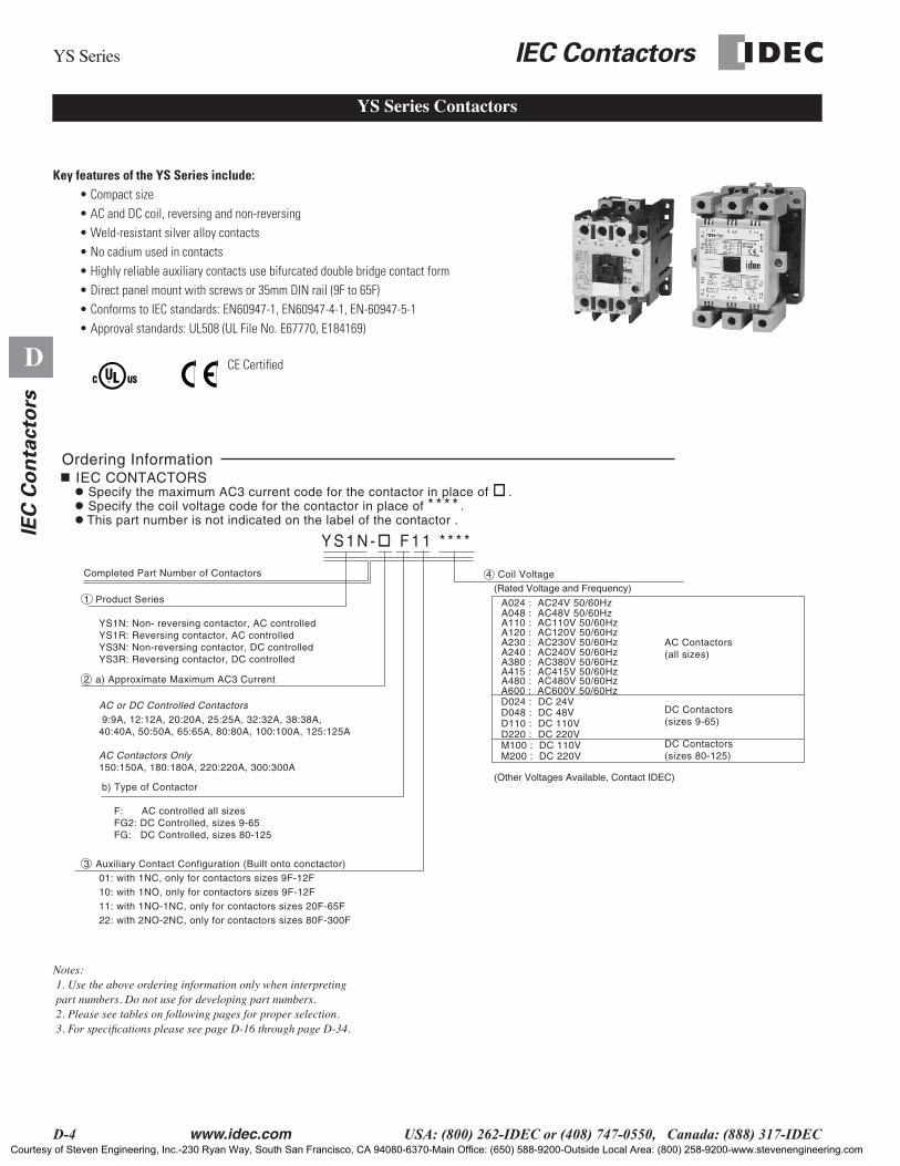
Key features of the YS Series include:
• Compact size• AC and DC coil, reversing and non-reversing• Weld-resistant silver alloy contacts• No cadium used in contacts• Highly reliable auxiliary contacts use bifurcated double bridge contact form• Direct panel mount with screws or 35mm DIN rail (9F to 65F)• Conforms to IEC standards: EN60947-1, EN60947-4-1, EN-60947-5-1• Approval standards: UL508 (UL File No. E67770, E184169)
Notes: 1. Use the above ordering information only when interpreting part numbers. Do not use for developing part numbers. 2. Please see tables on following pages for proper selection. 3. For specifications please see page D-16 through page D-34.
YS Series Contactors
Y S 1 N - F 1 1 * * * *
Ordering Information IEC CONTACTORS
Specify the coil voltage code for the contactor in place of * * * * . Specify the maximum AC3 current code for the contactor in place of .
This part number is not indicated on the label of the contactor .
Completed Part Number of Contactors
1 Product Series
YS1N: Non- reversing contactor, AC controlled YS1R: Reversing contactor, AC controlled YS3N: Non-reversing contactor, DC controlled YS3R: Reversing contactor, DC controlled
4 Coil Voltage
2 a) Approximate Maximum AC3 Current
AC or DC Controlled Contactors 9:9A, 12:12A, 20:20A, 25:25A, 32:32A, 38:38A, 40:40A, 50:50A, 65:65A, 80:80A, 100:100A, 125:125A
AC Contactors Only 150:150A, 180:180A, 220:220A, 300:300A
3 Auxiliary Contact Configuration (Built onto conctactor) 01: with 1NC, only for contactors sizes 9F-12F 10: with 1NO, only for contactors sizes 9F-12F 11: with 1NO-1NC, only for contactors sizes 20F-65F 22: with 2NO-2NC, only for contactors sizes 80F-300F
A024 : AC24V 50/60HzA048 : AC48V 50/60HzA110 : AC110V 50/60HzA120 : AC120V 50/60HzA230 : AC230V 50/60HzA240 : AC240V 50/60HzA380 : AC380V 50/60HzA415 : AC415V 50/60HzA480 : AC480V 50/60Hz
(Rated Voltage and Frequency)
(Other Voltages Available, Contact IDEC)
A600 : AC600V 50/60Hz
D110 : DC 110VD220 : DC 220VM100 : DC 110VM200 : DC 220V
D048 : DC 48VD024 : DC 24V
b) Type of Contactor
F: AC controlled all sizes FG2: DC Controlled, sizes 9-65 FG: DC Controlled, sizes 80-125
AC Contactors(all sizes)
DC Contactors(sizes 9-65)
DC Contactors(sizes 80-125)
CE Certified
Courtesy of Steven Engineering, Inc.-230 Ryan Way, South San Francisco, CA 94080-6370-Main Office: (650) 588-9200-Outside Local Area: (800) 258-9200-www.stevenengineering.com

IEC Contactors
YS Series
www.idec.com
USA: (800) 262-IDEC or (408) 747-0550, Canada: (888) 317-IDEC D-5
D
IEC
Co
nta
cto
rs
IEC Contactors, AC Controlled
Consult an IDEC representative for other coil voltages.For accessories, see page D-12.For specifications, see page D-16 through D-34.For dimensions, see pages D-35.For other application tables, see page D-51.
I
e
(Amps)kW AC3 Rating EN 60974-4-1 HP Rating per UL508 Auxiliary
ContactsPart Number3 Phase 1 Phase 3 Phase
AC1 AC3 220-230V
380-400V 500V 660-
690V 120V 230V 200-208V
220-240V
440-480V
550-600V N.O. N.C.
20 8.5 2.2 4 5.5 5.5 1/3 1 2 2 5 50 1 YS1N-9F01****
1 0 YS1N-9F10****
20 11.5 3 5.5 7.5 7.5 3/4 2 3 3 7.5 50 1 YS1N-12F01****
1 0 YS1N-12F10****
30 15.5 4 7.5 10 10 1 3 5 5 10 13.5 1 1 YS1N-20F11****
30 22 5.5 11 15 15 2 3 7.5 7.5 15 15 1 1 YS1N-25F11****
50 30 7.5 15 18.5 18.5 2 5 7.5 10 20 20 1 1 YS1N-32F11****
60 37 11 18.5 22 30 3 7.5 10 15 30 30 1 1 YS1N-38F11****
60 37 11 18.5 22 30 3 7.5 10 15 30 30 1 1 YS1N-40F11****
80 44 15 22 30 33 3 7.5 10 15 40 40 1 1 YS1N-50F11****
80 60 18.5 30 37 37 5 10 20 20 50 40 1 1 YS1N-65F11****
135 85 22 45 55 45 7.5 15 25 25 60 60 2 2 YS1N-80F22****
150 105 30 55 65 65 - - 30 35 60 75 2 2 YS1N-100F22****
150 114 37 60 75 75 - - 40 50 100 100 2 2 YS1N-125F22****
200 138 45 75 90 100 - - 40 50 100 125 2 2 YS1N-150F22****
240 179 55 95 110 110 - - 50 60 125 125 2 2 YS1N-180F22****
260 205 65 110 132 132 - - 60 75 150 150 2 2 YS1N-220F22****
350 300 90 160 160 200 - - 75 100 200 200 2 2 YS1N-300F22****
Codes for Control Circuit AC Voltages 50/60 Hz
Volts AC 50/60 Hz
24 48 120 220 240 380 415 480
Code to replace ****
A024 A048 A120 A220 A240 A380 A415 A480
YS1N Non-Reversing AC Contactors
Courtesy of Steven Engineering, Inc.-230 Ryan Way, South San Francisco, CA 94080-6370-Main Office: (650) 588-9200-Outside Local Area: (800) 258-9200-www.stevenengineering.com
YS Series
IEC Contactors
D-6
www.idec.com
USA: (800) 262-IDEC or (408) 747-0550, Canada: (888) 317-IDEC
D
IE
C C
on
tacto
rs
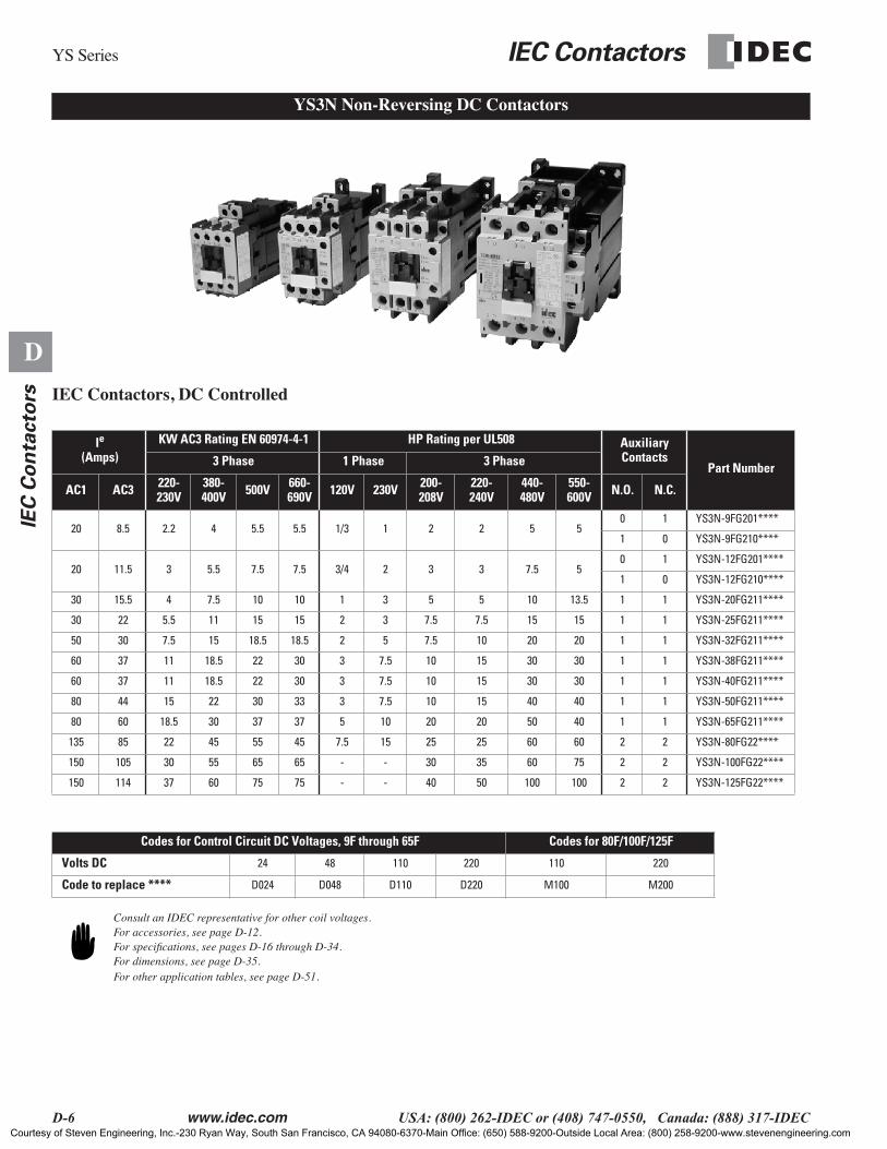
IEC Contactors, DC Controlled
Consult an IDEC representative for other coil voltages.For accessories, see page D-12.For specifications, see pages D-16 through D-34.For dimensions, see page D-35.For other application tables, see page D-51.
I
e
(Amps)KW AC3 Rating EN 60974-4-1 HP Rating per UL508 Auxiliary
ContactsPart Number3 Phase 1 Phase 3 Phase
AC1 AC3 220-230V
380-400V 500V 660-
690V 120V 230V 200-208V
220-240V
440-480V
550-600V N.O. N.C.
20 8.5 2.2 4 5.5 5.5 1/3 1 2 2 5 50 1 YS3N-9FG201****
1 0 YS3N-9FG210****
20 11.5 3 5.5 7.5 7.5 3/4 2 3 3 7.5 50 1 YS3N-12FG201****
1 0 YS3N-12FG210****
30 15.5 4 7.5 10 10 1 3 5 5 10 13.5 1 1 YS3N-20FG211****
30 22 5.5 11 15 15 2 3 7.5 7.5 15 15 1 1 YS3N-25FG211****
50 30 7.5 15 18.5 18.5 2 5 7.5 10 20 20 1 1 YS3N-32FG211****
60 37 11 18.5 22 30 3 7.5 10 15 30 30 1 1 YS3N-38FG211****
60 37 11 18.5 22 30 3 7.5 10 15 30 30 1 1 YS3N-40FG211****
80 44 15 22 30 33 3 7.5 10 15 40 40 1 1 YS3N-50FG211****
80 60 18.5 30 37 37 5 10 20 20 50 40 1 1 YS3N-65FG211****
135 85 22 45 55 45 7.5 15 25 25 60 60 2 2 YS3N-80FG22****
150 105 30 55 65 65 - - 30 35 60 75 2 2 YS3N-100FG22****
150 114 37 60 75 75 - - 40 50 100 100 2 2 YS3N-125FG22****
Codes for Control Circuit DC Voltages, 9F through 65F Codes for 80F/100F/125F
Volts DC
24 48 110 220 110 220
Code to replace ****
D024 D048 D110 D220 M100 M200
YS3N Non-Reversing DC Contactors
Courtesy of Steven Engineering, Inc.-230 Ryan Way, South San Francisco, CA 94080-6370-Main Office: (650) 588-9200-Outside Local Area: (800) 258-9200-www.stevenengineering.com
IEC Contactors
YS Series
www.idec.com
USA: (800) 262-IDEC or (408) 747-0550, Canada: (888) 317-IDEC D-7
D
IEC
Co
nta
cto
rs
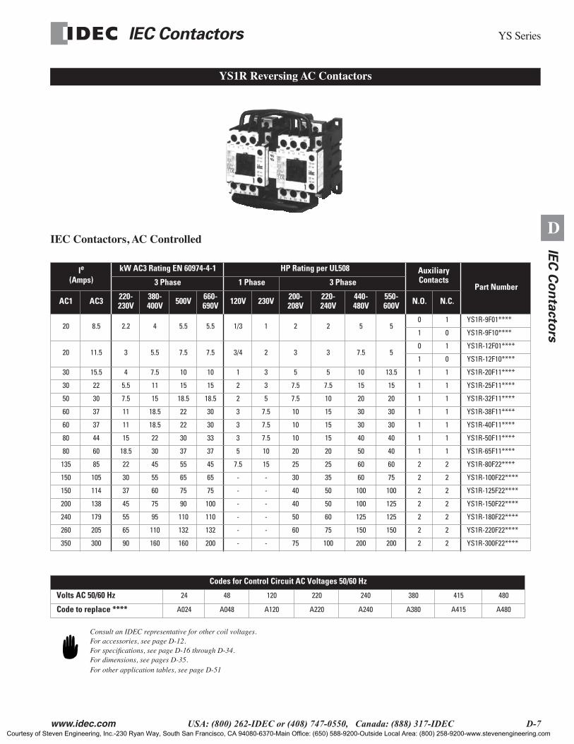
IEC Contactors, AC Controlled
Consult an IDEC representative for other coil voltages.For accessories, see page D-12.For specifications, see page D-16 through D-34.For dimensions, see pages D-35.For other application tables, see page D-51
I
e
(Amps)kW AC3 Rating EN 60974-4-1 HP Rating per UL508 Auxiliary
ContactsPart Number3 Phase 1 Phase 3 Phase
AC1 AC3 220-230V
380-400V 500V 660-
690V 120V 230V 200-208V
220-240V
440-480V
550-600V N.O. N.C.
20 8.5 2.2 4 5.5 5.5 1/3 1 2 2 5 50 1 YS1R-9F01****
1 0 YS1R-9F10****
20 11.5 3 5.5 7.5 7.5 3/4 2 3 3 7.5 50 1 YS1R-12F01****
1 0 YS1R-12F10****
30 15.5 4 7.5 10 10 1 3 5 5 10 13.5 1 1 YS1R-20F11****
30 22 5.5 11 15 15 2 3 7.5 7.5 15 15 1 1 YS1R-25F11****
50 30 7.5 15 18.5 18.5 2 5 7.5 10 20 20 1 1 YS1R-32F11****
60 37 11 18.5 22 30 3 7.5 10 15 30 30 1 1 YS1R-38F11****
60 37 11 18.5 22 30 3 7.5 10 15 30 30 1 1 YS1R-40F11****
80 44 15 22 30 33 3 7.5 10 15 40 40 1 1 YS1R-50F11****
80 60 18.5 30 37 37 5 10 20 20 50 40 1 1 YS1R-65F11****
135 85 22 45 55 45 7.5 15 25 25 60 60 2 2 YS1R-80F22****
150 105 30 55 65 65 - - 30 35 60 75 2 2 YS1R-100F22****
150 114 37 60 75 75 - - 40 50 100 100 2 2 YS1R-125F22****
200 138 45 75 90 100 - - 40 50 100 125 2 2 YS1R-150F22****
240 179 55 95 110 110 - - 50 60 125 125 2 2 YS1R-180F22****
260 205 65 110 132 132 - - 60 75 150 150 2 2 YS1R-220F22****
350 300 90 160 160 200 - - 75 100 200 200 2 2 YS1R-300F22****
Codes for Control Circuit AC Voltages 50/60 Hz
Volts AC 50/60 Hz
24 48 120 220 240 380 415 480
Code to replace ****
A024 A048 A120 A220 A240 A380 A415 A480
YS1R Reversing AC Contactors
Courtesy of Steven Engineering, Inc.-230 Ryan Way, South San Francisco, CA 94080-6370-Main Office: (650) 588-9200-Outside Local Area: (800) 258-9200-www.stevenengineering.com
YS Series
IEC Contactors
D-8
www.idec.com
USA: (800) 262-IDEC or (408) 747-0550, Canada: (888) 317-IDEC
D
IE
C C
on
tacto
rs
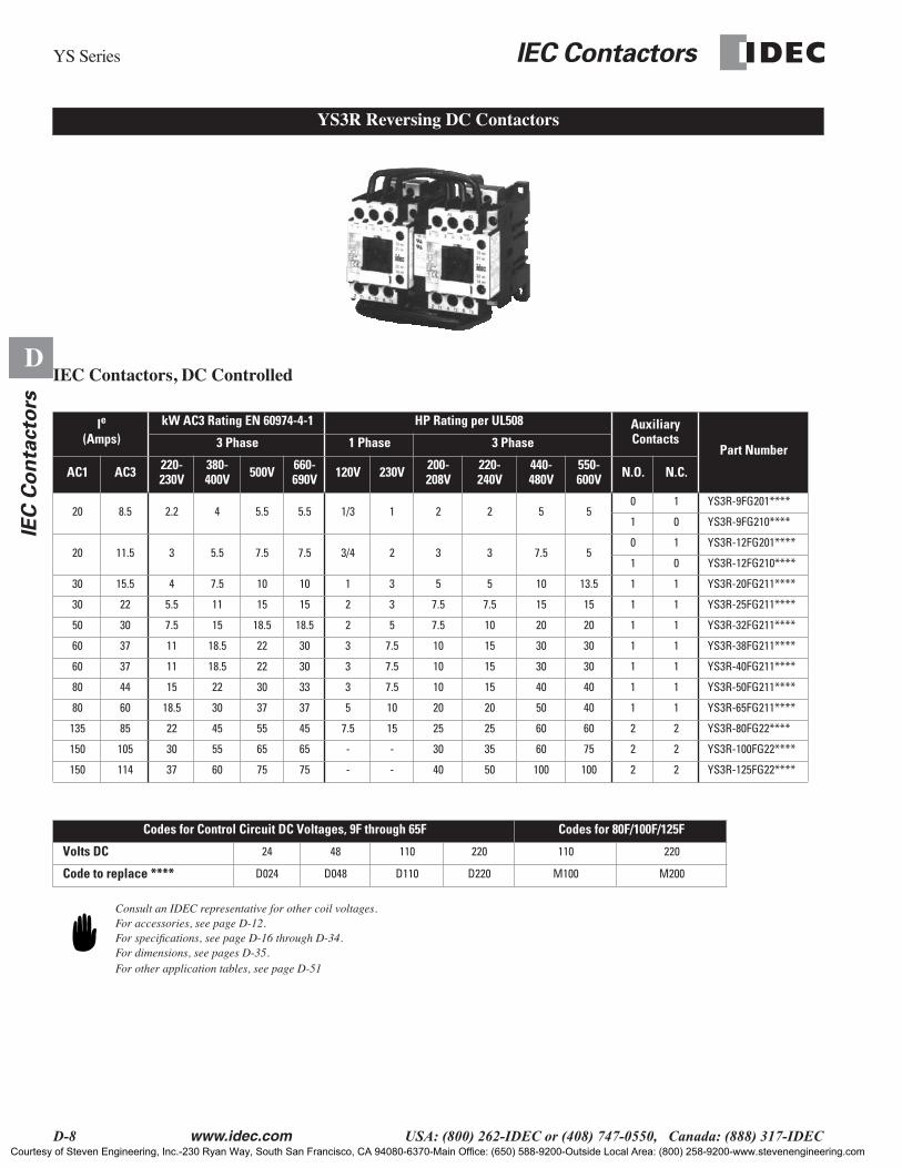
IEC Contactors, DC Controlled
Consult an IDEC representative for other coil voltages.For accessories, see page D-12.For specifications, see page D-16 through D-34.For dimensions, see pages D-35.For other application tables, see page D-51
I
e
(Amps)kW AC3 Rating EN 60974-4-1 HP Rating per UL508 Auxiliary
ContactsPart Number3 Phase 1 Phase 3 Phase
AC1 AC3 220-230V
380-400V 500V 660-
690V 120V 230V 200-208V
220-240V
440-480V
550-600V N.O. N.C.
20 8.5 2.2 4 5.5 5.5 1/3 1 2 2 5 50 1 YS3R-9FG201****
1 0 YS3R-9FG210****
20 11.5 3 5.5 7.5 7.5 3/4 2 3 3 7.5 50 1 YS3R-12FG201****
1 0 YS3R-12FG210****
30 15.5 4 7.5 10 10 1 3 5 5 10 13.5 1 1 YS3R-20FG211****
30 22 5.5 11 15 15 2 3 7.5 7.5 15 15 1 1 YS3R-25FG211****
50 30 7.5 15 18.5 18.5 2 5 7.5 10 20 20 1 1 YS3R-32FG211****
60 37 11 18.5 22 30 3 7.5 10 15 30 30 1 1 YS3R-38FG211****
60 37 11 18.5 22 30 3 7.5 10 15 30 30 1 1 YS3R-40FG211****
80 44 15 22 30 33 3 7.5 10 15 40 40 1 1 YS3R-50FG211****
80 60 18.5 30 37 37 5 10 20 20 50 40 1 1 YS3R-65FG211****
135 85 22 45 55 45 7.5 15 25 25 60 60 2 2 YS3R-80FG22****
150 105 30 55 65 65 - - 30 35 60 75 2 2 YS3R-100FG22****
150 114 37 60 75 75 - - 40 50 100 100 2 2 YS3R-125FG22****
Codes for Control Circuit DC Voltages, 9F through 65F Codes for 80F/100F/125F
Volts DC
24 48 110 220 110 220
Code to replace ****
D024 D048 D110 D220 M100 M200
YS3R Reversing DC Contactors
Courtesy of Steven Engineering, Inc.-230 Ryan Way, South San Francisco, CA 94080-6370-Main Office: (650) 588-9200-Outside Local Area: (800) 258-9200-www.stevenengineering.com

IEC Contactors
YS Series
www.idec.com
USA: (800) 262-IDEC or (408) 747-0550, Canada: (888) 317-IDEC D-9
D
IEC
Co
nta
cto
rs
YS1T-RHA thermal overload relays are designed to meet the heating characteristics of induction motors with insulation class type E. Various functions can beselected by using the reset button and adjustment button on top of the thermal overload relay.
Key features of the YS1T Series include:
• Single-phase protection• Bi-metallic• Compact and sturdy• Ambient temperature compensation mechanism• Manual/automatic reset operation• 3 element type with phase failure protection• Conforms to IEC Standards EN60947-1, EN60947-4-1, EN60947-5-1• Approval standards UL508, UL File No. E158813
Notes: 1. Use the above ordering information only when interpreting part numbers. Do not use for developing part numbers. 2. For applicable combinations of contactors and thermal overload relays, please consult following page.3. For specifications and settings please see pages D-16 through D-34.
Thermal Overload Relays
Ordering Information THERMAL OVERLOAD RELAYS
•Part number is indicated on the label of the thermal overload relay.
3 Current setting range code
Adjustablecurrent range
0.1 - 0.16P13 :0.16 - 0.25P20 :0.25 - 0.4P30 :
0.4 - 0.63P50 :0.63 - 1P80 :
1 - 1.61P3 :1.25 - 21P5 :1.6 - 2.52P0 :2.5 - 43P0 :
4 - 65P0 :5.5 - 87P0 :
7 - 108P5 :9 - 1311P :
12 - 1815P :17 - 2521P :23 - 3227P :28 - 3632P :30 - 4035P :
37 - 5043P :48 - 6556P :55 - 8068P :65 - 9580P :85 - 125105 :
110 - 160135 :125 - 185155 :
96 - 155
128 - 200
120* :
160* : 180* : 240* :
150 - 240192 - 300
Current settingrange code
Adjustablecurrent range
Y S 1 T- R H A D
Completed Part Number of Thermal Overload Relay
1 Product Series
2 Applicable Maximum Motor Current 25F: 25A, contactor sizes 9F,12F, 20F, 25F 38F: 40A, contactor sizes 32F, 38F 65F: 65A, contactor sizes 40F, 50F, 65F 125F: 125A, contactor sizes 80F, 100F, 125F 150F: 150A, contactor sizes 150F or 180F 180F: 180A, contactor sizes 150F or 180F *300F: 300A, contactor size 220F or 300F *400F: 400A, contactor size 220F or 300F Note: *With Current Transformer (CT)
4 Function D: 3-element Type with Phase Failure Protection
Note :*With CT
Verify appropriate current setting range code with the correct size overload using the complete part list onthe following page.
Courtesy of Steven Engineering, Inc.-230 Ryan Way, South San Francisco, CA 94080-6370-Main Office: (650) 588-9200-Outside Local Area: (800) 258-9200-www.stevenengineering.com

YS Series
IEC Contactors
D-10
www.idec.com
USA: (800) 262-IDEC or (408) 747-0550, Canada: (888) 317-IDEC
D
IE
C C
on
tacto
rs
Thermal Overload Relays
Product Series Current Range Range Code Part Number for Overload Applicable Contactor Size
0.1-0.16A P13 YS1T-RHA25FP13D
YS-9FYS-12FYS-20FYS-25F
0.16-0.25A P20 YS1T-RHA25FP20D
0.25-0.4A P30 YS1T-RHA25FP30D
0.40-0.63A P50 YS1T-RHA25FP50D
0.63-1.0A P80 YS1T-RHA25FP80D
1.0-1.6A 1P3 YS1T-RHA25F1P3D
1.25-2.0A 1P5 YS1T-RHA25F1P5D
1.6-2.5A 2P0 YS1T-RHA25F2P0D
2.5-4.0A 3P0 YS1T-RHA25F3P0D
4.0-6.0A 5P0 YS1T-RHA25F5P0D
5.5-8.0A 7P0 YS1T-RHA25F7P0D
7.0-10.0A 8P5 YS1T-RHA25F8P5D
9.0-13.0A 11P YS1T-RHA25F11PD
12.0-18.0A 15P YS1T-RHA25F15PD
17.0-25.0 21P YS1T-RHA25F21PD
9-13A 11P YS1T-RHA38F11PD
YS-32FYS-38F
12-18A 15P YS1T-RHA38F15PD
17-25A 21P YS1T-RHA38F21PD
23-32A 27P YS1T-RHA38F27PD
28-36A 32P YS1T-RHA38F32PD
30-40A 35P YS1T-RHA38F35PD
12-18A 15P YS1T-RHA65F15PD
YS-40FYS-50FYS-65F
17-25A 21P YS1T-RHA65F21PD
23-32A 27P YS1T-RHA65F27PD
28-36A 32P YS1T-RHA65F32PD
30-40A 35P YS1T-RHA65F35PD
37-50A 43P YS1T-RHA65F43PD
48-65A 56P YS1T-RHA65F56PD
37-50A 43P YS1T-RHA125F43PD
YS-80FYS-100FYS-125F
48-65A 56P YS1T-RHA125F56PD
55-80A 68P YS1T-RHA125F68PD
65-95A 80P YS1T-RHA125F80PD
85-125A 105 YS1T-RHA125F105D
65-95A 80P YS1T-RHA150F80PDYS-150FYS-180F85-125A 105 YS1T-RHA150F105D
105-160A 135 YS1T-RHA150F135D
85-125A 105 YS1T-RHA180F105DYS-150FYS-180F105-160A 135 YS1T-RHA180F135D
125-185A 155 YS1T-RHA180F155D
96-150A 120 YS1T-RHA300F120D
YS-220FYS-300F
150-240A 180 YS1T-RHA300F180D
128-200A 160 YS1T-RHA400F160D
200-300A 240 YS1T-RHA400F240D
YS1T-RHA25F
YS1T-RHA38F
YS1T-RHA65F
YS1T-RHA125F
YS1T-RHA150F
YS1T-RHA180F
*YS1T-RHA300F*YS1T-RHA400F
*with current transformer
Courtesy of Steven Engineering, Inc.-230 Ryan Way, South San Francisco, CA 94080-6370-Main Office: (650) 588-9200-Outside Local Area: (800) 258-9200-www.stevenengineering.com

IEC Contactors
YS Series
www.idec.com
USA: (800) 262-IDEC or (408) 747-0550, Canada: (888) 317-IDEC D-11
D
IEC
Co
nta
cto
rs
YS Series Starters
Ordering Instructions for an Assembled StarterSTARTERS (Contactors with Thermal Overload Relay)
• Select the correct size overload from page D-9 throught D-10.
Y S 2 R - F D 1 1 * * * * T # # #
Completed Part Number of Reversing Starter
1 Product Series
• Select the appropriate contactor (AC or DC, reversing or non-reversing) from pages D-5 through D-8.
• The complete assembled part number is the same as the contactor with the following changes: (See examples below)
5 Coil Voltage (Replaced exactly from contactor P/N)
2 Maximum AC3 Current (replaced exactly from contactor P/N)
3 Thermal Overload Relay
D: 3-element Type with Phase Failure Protection
4 Auxiliary Contact Configuration (Replaced exactly from contactor P/N)
6 Thermal Overload Relay, Type YS1T-RHA T: Thermal Overload Relay + ###: Three character code designating of Current Setting Range Code (See page D-10.)
01: with 1NC, for contactor sizes 9F-12F 10: with 1NO, for contactor sizes 9F-12F 11: with 1NO-1NC, for contactor sizes 20F-65F 22: with 2NO-2NC, for contactor sizes 80F-300F
YS1N contactor ----> YS2N AC non-reversing StarterYS1R contactor ----> YS2R AC reversing StarterYS3N contactor ----> YS4N DC non-reversing StarterYS3R contactor ----> YS4R DC reversing Starter
F : i s r e p l a c e d by s i ze , 9 - 3 0 0 fo r AC c o n t r o l l e d F G 2 : i s r e p l a c e d by s i ze , 9 - 6 5 fo r D C c o n t r o l l e d F G : i s r e p l a c e d by s i ze , 8 0 - 1 2 5 fo r D C c o n t r o l l e d
EXAMPLE #1 : Contactor : Y S 1 R - 9 F 1 0 A 1 2 0 + Overload: Y S 1 T- R H A 2 5 F 5 P 0 D
65421
STARTER: Y S 2 R - 9 F D 1 0 A 1 2 0 T 5 P 0
65421 3
EXAMPLE #2 : Contactor : Y S 3 N - 6 5 F G 2 1 1 D 0 2 4 + Overload: Y S 1 T- R H A 6 5 F 4 3 P D
65421
STARTER: Y S 4 N - 6 5 F G 2 D 1 1 D 0 2 4 T 4 3 P
65421 3
Courtesy of Steven Engineering, Inc.-230 Ryan Way, South San Francisco, CA 94080-6370-Main Office: (650) 588-9200-Outside Local Area: (800) 258-9200-www.stevenengineering.com
Accessories
IEC Contactors
D-12
www.idec.com
USA: (800) 262-IDEC or (408) 747-0550, Canada: (888) 317-IDEC
D
IE
C C
on
tacto
rs
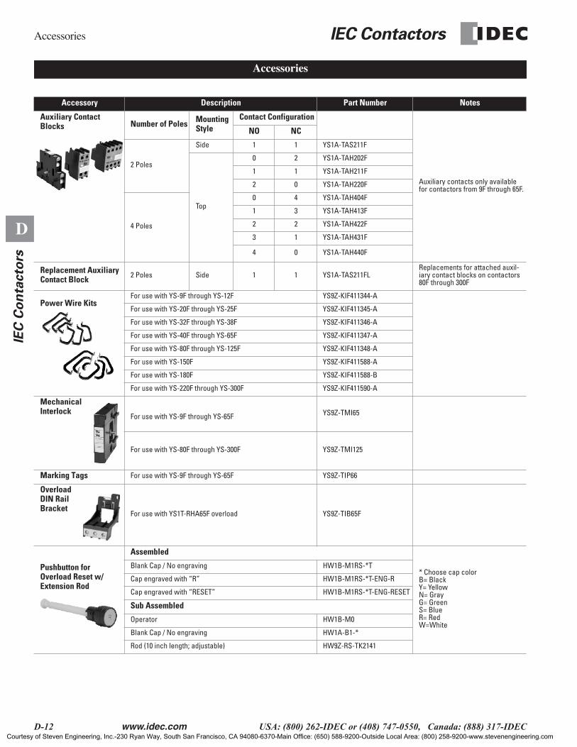
Accessory Description Part Number Notes
Auxiliary Contact Blocks Number of Poles Mounting
StyleContact Configuration
Auxiliary contacts only available for contactors from 9F through 65F.
NO NC
2 Poles
Side 1 1 YS1A-TAS211F
Top
0 2 YS1A-TAH202F
1 1 YS1A-TAH211F
2 0 YS1A-TAH220F
4 Poles
0 4 YS1A-TAH404F
1 3 YS1A-TAH413F
2 2 YS1A-TAH422F
3 1 YS1A-TAH431F
4 0 YS1A-TAH440F
Replacement Auxiliary Contact Block
2 Poles Side 1 1 YS1A-TAS211FLReplacements for attached auxil-iary contact blocks on contactors 80F through 300F
Power Wire Kits
For use with YS-9F through YS-12F YS9Z-KIF411344-A
For use with YS-20F through YS-25F YS9Z-KIF411345-A
For use with YS-32F through YS-38F YS9Z-KIF411346-A
For use with YS-40F through YS-65F YS9Z-KIF411347-A
For use with YS-80F through YS-125F YS9Z-KIF411348-A
For use with YS-150F YS9Z-KIF411588-A
For use with YS-180F YS9Z-KIF411588-B
For use with YS-220F through YS-300F YS9Z-KIF411590-A
Mechanical Interlock
For use with YS-9F through YS-65F YS9Z-TMI65
For use with YS-80F through YS-300F YS9Z-TMI125
Marking Tags
For use with YS-9F through YS-65F YS9Z-TIP66
Overload DIN Rail Bracket
For use with YS1T-RHA65F overload YS9Z-TIB65F
Pushbutton for Overload Reset w/ Extension Rod
Assembled
* Choose cap colorB= BlackY= YellowN= GrayG= GreenS= BlueR= RedW=White
Blank Cap / No engraving HW1B-M1RS-*T
Cap engraved with “R” HW1B-M1RS-*T-ENG-R
Cap engraved with “RESET” HW1B-M1RS-*T-ENG-RESET
Sub Assembled
Operator HW1B-M0
Blank Cap / No engraving HW1A-B1-*
Rod (10 inch length; adjustable) HW9Z-RS-TK2141
Accessories
Courtesy of Steven Engineering, Inc.-230 Ryan Way, South San Francisco, CA 94080-6370-Main Office: (650) 588-9200-Outside Local Area: (800) 258-9200-www.stevenengineering.com
IEC Contactors Accessories
www.idec.com USA: (800) 262-IDEC or (408) 747-0550, Canada: (888) 317-IDEC D-13
D
IEC
Co
nta
cto
rs
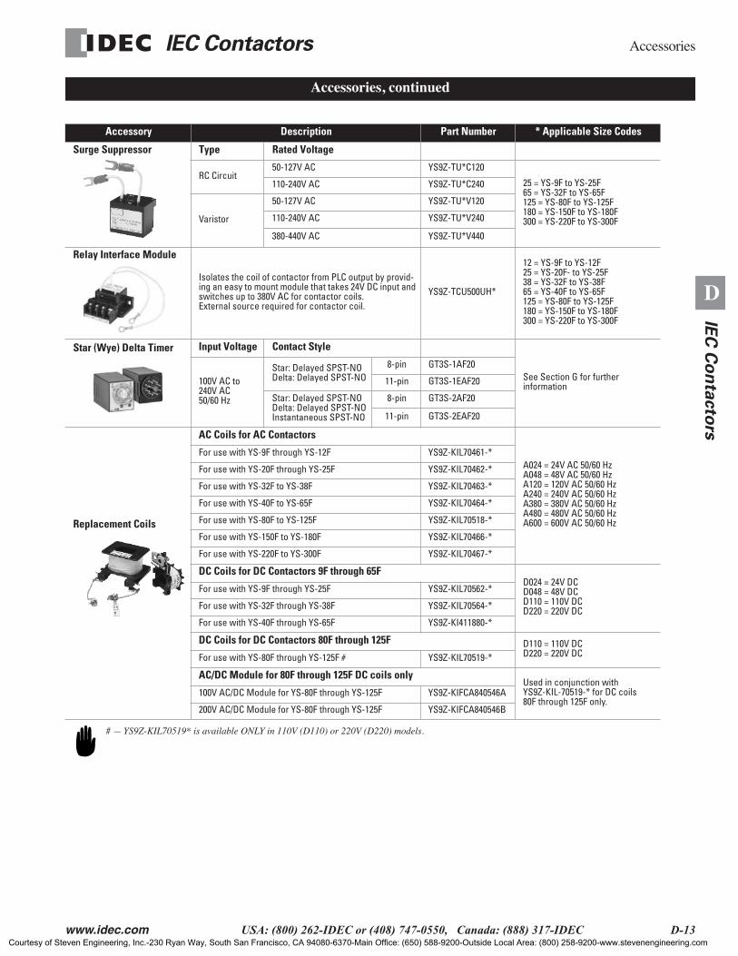
Accessory Description Part Number * Applicable Size Codes
Surge Suppressor Type Rated Voltage
RC Circuit50-127V AC YS9Z-TU*C120
25 = YS-9F to YS-25F65 = YS-32F to YS-65F125 = YS-80F to YS-125F180 = YS-150F to YS-180F300 = YS-220F to YS-300F
110-240V AC YS9Z-TU*C240
Varistor
50-127V AC YS9Z-TU*V120
110-240V AC YS9Z-TU*V240
380-440V AC YS9Z-TU*V440
Relay Interface Module
Isolates the coil of contactor from PLC output by provid-ing an easy to mount module that takes 24V DC input and switches up to 380V AC for contactor coils.External source required for contactor coil.
YS9Z-TCU500UH*
12 = YS-9F to YS-12F25 = YS-20F- to YS-25F38 = YS-32F to YS-38F65 = YS-40F to YS-65F125 = YS-80F to YS-125F180 = YS-150F to YS-180F300 = YS-220F to YS-300F
Star (Wye) Delta Timer Input Voltage Contact Style
See Section G for further information100V AC to
240V AC 50/60 Hz
Star: Delayed SPST-NODelta: Delayed SPST-NO
8-pin GT3S-1AF20
11-pin GT3S-1EAF20
Star: Delayed SPST-NODelta: Delayed SPST-NOInstantaneous SPST-NO
8-pin GT3S-2AF20
11-pin GT3S-2EAF20
Replacement Coils
AC Coils for AC Contactors
A024 = 24V AC 50/60 HzA048 = 48V AC 50/60 HzA120 = 120V AC 50/60 HzA240 = 240V AC 50/60 HzA380 = 380V AC 50/60 HzA480 = 480V AC 50/60 HzA600 = 600V AC 50/60 Hz
For use with YS-9F through YS-12F YS9Z-KIL70461-*
For use with YS-20F through YS-25F YS9Z-KIL70462-*
For use with YS-32F to YS-38F YS9Z-KIL70463-*
For use with YS-40F to YS-65F YS9Z-KIL70464-*
For use with YS-80F to YS-125F YS9Z-KIL70518-*
For use with YS-150F to YS-180F YS9Z-KIL70466-*
For use with YS-220F to YS-300F YS9Z-KIL70467-*
DC Coils for DC Contactors 9F through 65FD024 = 24V DCD048 = 48V DCD110 = 110V DCD220 = 220V DC
For use with YS-9F through YS-25F YS9Z-KIL70562-*
For use with YS-32F through YS-38F YS9Z-KIL70564-*
For use with YS-40F through YS-65F YS9Z-KI411880-*
DC Coils for DC Contactors 80F through 125F D110 = 110V DCD220 = 220V DCFor use with YS-80F through YS-125F # YS9Z-KIL70519-*
AC/DC Module for 80F through 125F DC coils onlyUsed in conjunction with YS9Z-KIL-70519-* for DC coils 80F through 125F only.
100V AC/DC Module for YS-80F through YS-125F YS9Z-KIFCA840546A
200V AC/DC Module for YS-80F through YS-125F YS9Z-KIFCA840546B
Accessories, continued
# — YS9Z-KIL70519* is available ONLY in 110V (D110) or 220V (D220) models.
Courtesy of Steven Engineering, Inc.-230 Ryan Way, South San Francisco, CA 94080-6370-Main Office: (650) 588-9200-Outside Local Area: (800) 258-9200-www.stevenengineering.com
Accessories IEC Contactors
D-14 www.idec.com USA: (800) 262-IDEC or (408) 747-0550, Canada: (888) 317-IDEC
D
IEC
Co
nta
cto
rs
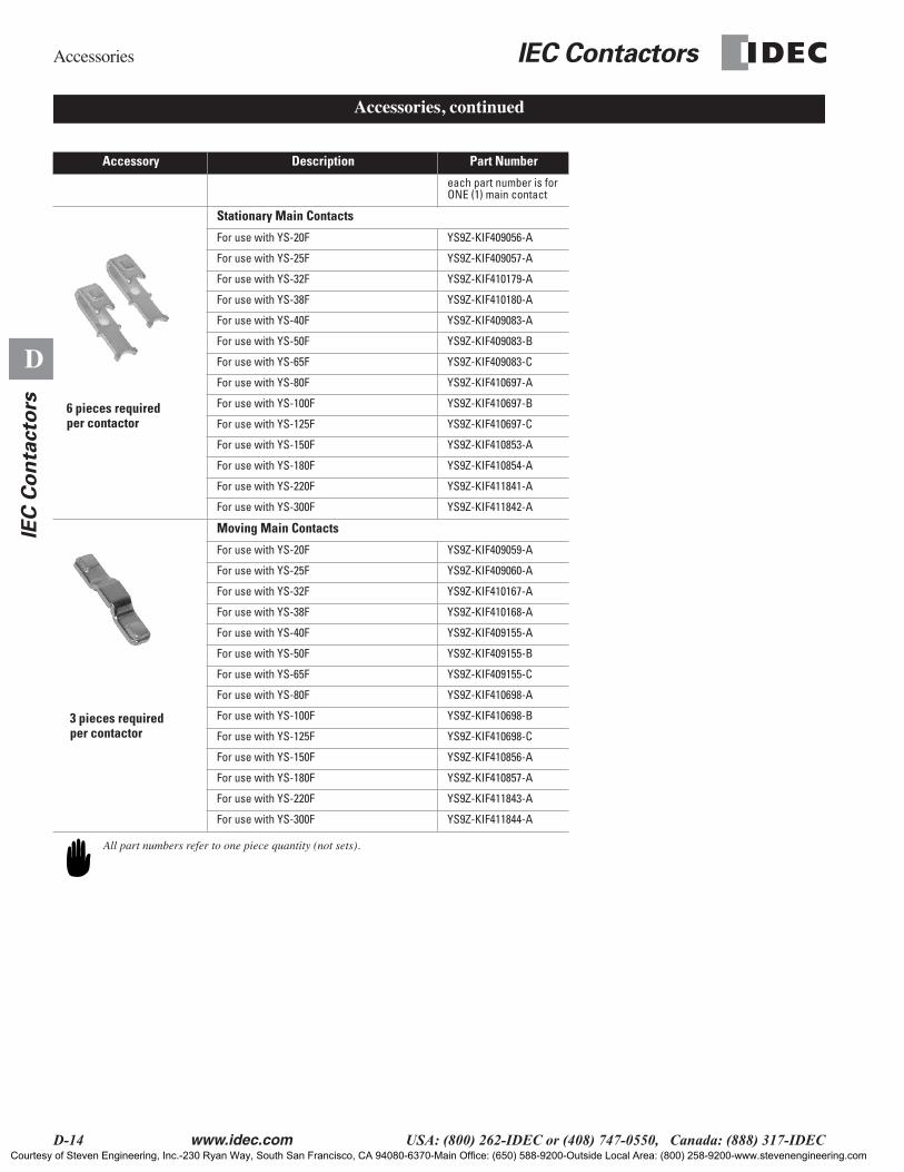
Accessory Description Part Number
each part number is for ONE (1) main contact
Stationary Main Contacts
For use with YS-20F YS9Z-KIF409056-A
For use with YS-25F YS9Z-KIF409057-A
For use with YS-32F YS9Z-KIF410179-A
For use with YS-38F YS9Z-KIF410180-A
For use with YS-40F YS9Z-KIF409083-A
For use with YS-50F YS9Z-KIF409083-B
For use with YS-65F YS9Z-KIF409083-C
For use with YS-80F YS9Z-KIF410697-A
For use with YS-100F YS9Z-KIF410697-B
For use with YS-125F YS9Z-KIF410697-C
For use with YS-150F YS9Z-KIF410853-A
For use with YS-180F YS9Z-KIF410854-A
For use with YS-220F YS9Z-KIF411841-A
For use with YS-300F YS9Z-KIF411842-A
Moving Main Contacts
For use with YS-20F YS9Z-KIF409059-A
For use with YS-25F YS9Z-KIF409060-A
For use with YS-32F YS9Z-KIF410167-A
For use with YS-38F YS9Z-KIF410168-A
For use with YS-40F YS9Z-KIF409155-A
For use with YS-50F YS9Z-KIF409155-B
For use with YS-65F YS9Z-KIF409155-C
For use with YS-80F YS9Z-KIF410698-A
For use with YS-100F YS9Z-KIF410698-B
For use with YS-125F YS9Z-KIF410698-C
For use with YS-150F YS9Z-KIF410856-A
For use with YS-180F YS9Z-KIF410857-A
For use with YS-220F YS9Z-KIF411843-A
For use with YS-300F YS9Z-KIF411844-A
Accessories, continued
All part numbers refer to one piece quantity (not sets).
6 pieces required per contactor
3 pieces required per contactor
Courtesy of Steven Engineering, Inc.-230 Ryan Way, South San Francisco, CA 94080-6370-Main Office: (650) 588-9200-Outside Local Area: (800) 258-9200-www.stevenengineering.com

IEC Contactors Accessories
www.idec.com USA: (800) 262-IDEC or (408) 747-0550, Canada: (888) 317-IDEC D-15
D
IEC
Co
nta
cto
rs
Part Number Description For Use With
BAA1000
35mm Aluminum DIN Rail 7.5 mm deep1 meter long YS1N-9F through YS1N-38F Contactors
BNDN1000
35mm Aluminum DIN Rail 10.5 mm deep. 1 meter long YS1N-9F through YS1N-38F Contactors
YS9Z-TIP66 Markers
Plastic replacement markerssold in 100 piece packs
YS-9F through YS-65F series contactors, overloads relays and top mount auxiliary contact blocks.
BNL8
DIN Rail End Stop used to preventcontactors from sliding on DIN rails
YS1N-32F/YS1N-38F & YS1R reversing contactors
BNL5
DIN Rail End Stop used to preventcontactors from sliding on DIN rails
YS1N-9FYS1N-12FYS1N-20FYS1N-25FContactors
SR2P-05C
8-pin DIN mount Finger-safe (IP20)screw terminal socket
GT3S-1AF20 timer (8 pin)GT3S-2AF20 timer (8 pin)
SR2P-06
8-pin DIN mount screw terminal socketopen terminal construction GT3S-1AF20 timer (8 pin)
GT3S-2AF20 timer (8 pin)
SR3P-05C
11-pin DIN mount finger-safe (IP20)screw terminal socket
GT3S-1EAF20 timer (11pin)GT3S-2EAF20 timer (11pin)
SR3P-06
11-pin DIN mount screw terminal socketopen terminal construction
GT3S-1EAF20 (11 pin)GT3S-2EAF20 (11 pin)
Accessories, continued
Courtesy of Steven Engineering, Inc.-230 Ryan Way, South San Francisco, CA 94080-6370-Main Office: (650) 588-9200-Outside Local Area: (800) 258-9200-www.stevenengineering.com
Specifications IEC Contactors
D-16 www.idec.com USA: (800) 262-IDEC or (408) 747-0550, Canada: (888) 317-IDEC
D
IEC
Co
nta
cto
rs
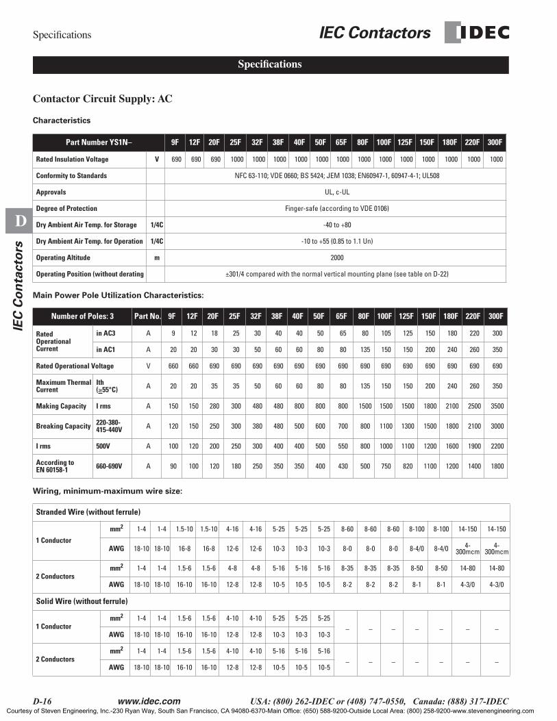
Contactor Circuit Supply: AC
Characteristics
Main Power Pole Utilization Characteristics:
Wiring, minimum-maximum wire size:
Part Number YS1N– 9F 12F 20F 25F 32F 38F 40F 50F 65F 80F 100F 125F 150F 180F 220F 300F
Rated Insulation Voltage V 690 690 690 1000 1000 1000 1000 1000 1000 1000 1000 1000 1000 1000 1000 1000
Conformity to Standards NFC 63-110; VDE 0660; BS 5424; JEM 1038; EN60947-1, 60947-4-1; UL508
Approvals UL, c-UL
Degree of Protection Finger-safe (according to VDE 0106)
Dry Ambient Air Temp. for Storage 1/4C -40 to +80
Dry Ambient Air Temp. for Operation 1/4C -10 to +55 (0.85 to 1.1 Un)
Operating Altitude m 2000
Operating Position (without derating ±301/4 compared with the normal vertical mounting plane (see table on D-22)
Number of Poles: 3 Part No. 9F 12F 20F 25F 32F 38F 40F 50F 65F 80F 100F 125F 150F 180F 220F 300F
Rated Operational Current
in AC3 A 9 12 18 25 30 40 40 50 65 80 105 125 150 180 220 300
in AC1 A 20 20 30 30 50 60 60 80 80 135 150 150 200 240 260 350
Rated Operational Voltage V 660 660 690 690 690 690 690 690 690 690 690 690 690 690 690 690
Maximum Thermal Current
Ith (≥55°C) A 20 20 35 35 50 60 60 80 80 135 150 150 200 240 260 350
Making Capacity I rms A 150 150 280 300 480 480 800 800 800 1500 1500 1500 1800 2100 2500 3500
Breaking Capacity 220-380-415-440V A 120 150 250 300 380 480 500 600 700 800 1100 1300 1500 1800 2100 3000
I rms 500V A 100 120 200 250 300 400 400 500 550 800 1000 1100 1200 1600 1900 2200
According to EN 60158-1 660-690V A 90 100 120 180 250 350 350 400 430 500 750 820 1100 1200 1400 1800
Stranded Wire (without ferrule)
1 Conductor
mm2 1-4 1-4 1.5-10 1.5-10 4-16 4-16 5-25 5-25 5-25 8-60 8-60 8-60 8-100 8-100 14-150 14-150
AWG 18-10 18-10 16-8 16-8 12-6 12-6 10-3 10-3 10-3 8-0 8-0 8-0 8-4/0 8-4/0 4-300mcm
4-300mcm
2 Conductorsmm2 1-4 1-4 1.5-6 1.5-6 4-8 4-8 5-16 5-16 5-16 8-35 8-35 8-35 8-50 8-50 14-80 14-80
AWG 18-10 18-10 16-10 16-10 12-8 12-8 10-5 10-5 10-5 8-2 8-2 8-2 8-1 8-1 4-3/0 4-3/0
Solid Wire (without ferrule)
1 Conductormm2 1-4 1-4 1.5-6 1.5-6 4-10 4-10 5-25 5-25 5-25
_ _ _ _ _ _ _AWG 18-10 18-10 16-10 16-10 12-8 12-8 10-3 10-3 10-3
2 Conductorsmm2 1-4 1-4 1.5-6 1.5-6 4-10 4-10 5-16 5-16 5-16
_ _ _ _ _ _ _AWG 18-10 18-10 16-10 16-10 12-8 12-8 10-5 10-5 10-5
Specifications
Courtesy of Steven Engineering, Inc.-230 Ryan Way, South San Francisco, CA 94080-6370-Main Office: (650) 588-9200-Outside Local Area: (800) 258-9200-www.stevenengineering.com
IEC Contactors Specifications
www.idec.com USA: (800) 262-IDEC or (408) 747-0550, Canada: (888) 317-IDEC D-17
D
IEC
Co
nta
cto
rs
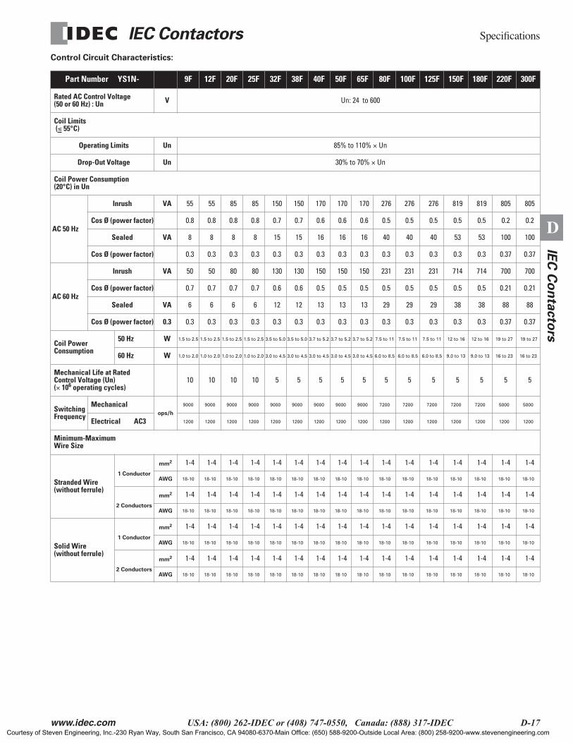
Control Circuit Characteristics:
Part Number YS1N- 9F 12F 20F 25F 32F 38F 40F 50F 65F 80F 100F 125F 150F 180F 220F 300F
Rated AC Control Voltage(50 or 60 Hz) : Un V Un: 24 to 600
Coil Limits (≤ 55°C)
Operating Limits Un 85% to 110% × Un
Drop-Out Voltage Un 30% to 70% × Un
Coil Power Consumption (20°C) in Un
AC 50 Hz
Inrush VA 55 55 85 85 150 150 170 170 170 276 276 276 819 819 805 805
Cos Ø (power factor) 0.8 0.8 0.8 0.8 0.7 0.7 0.6 0.6 0.6 0.5 0.5 0.5 0.5 0.5 0.2 0.2
Sealed VA 8 8 8 8 15 15 16 16 16 40 40 40 53 53 100 100
Cos Ø (power factor) 0.3 0.3 0.3 0.3 0.3 0.3 0.3 0.3 0.3 0.3 0.3 0.3 0.3 0.3 0.37 0.37
AC 60 Hz
Inrush VA 50 50 80 80 130 130 150 150 150 231 231 231 714 714 700 700
Cos Ø (power factor) 0.7 0.7 0.7 0.7 0.6 0.6 0.5 0.5 0.5 0.5 0.5 0.5 0.5 0.5 0.21 0.21
Sealed VA 6 6 6 6 12 12 13 13 13 29 29 29 38 38 88 88
Cos Ø (power factor) 0.3 0.3 0.3 0.3 0.3 0.3 0.3 0.3 0.3 0.3 0.3 0.3 0.3 0.3 0.3 0.37 0.37
Coil Power Consumption
50 Hz W 1.5 to 2.5 1.5 to 2.5 1.5 to 2.5 1.5 to 2.5 3.5 to 5.0 3.5 to 5.0 3.7 to 5.2 3.7 to 5.2 3.7 to 5.2 7.5 to 11 7.5 to 11 7.5 to 11 12 to 16 12 to 16 19 to 27 19 to 27
60 Hz W 1.0 to 2.0 1.0 to 2.0 1.0 to 2.0 1.0 to 2.0 3.0 to 4.5 3.0 to 4.5 3.0 to 4.5 3.0 to 4.5 3.0 to 4.5 6.0 to 8.5 6.0 to 8.5 6.0 to 8.5 9.0 to 13 9.0 to 13 16 to 23 16 to 23
Mechanical Life at Rated Control Voltage (Un) (× 106 operating cycles)
10 10 10 10 5 5 5 5 5 5 5 5 5 5 5 5
Switching Frequency
Mechanicalops/h
9000 9000 9000 9000 9000 9000 9000 9000 9000 7200 7200 7200 7200 7200 5000 5000
Electrical AC3 1200 1200 1200 1200 1200 1200 1200 1200 1200 1200 1200 1200 1200 1200 1200 1200
Minimum-Maximum Wire Size
Stranded Wire (without ferrule)
1 Conductor
mm2 1-4 1-4 1-4 1-4 1-4 1-4 1-4 1-4 1-4 1-4 1-4 1-4 1-4 1-4 1-4 1-4
AWG 18-10 18-10 18-10 18-10 18-10 18-10 18-10 18-10 18-10 18-10 18-10 18-10 18-10 18-10 18-10 18-10
2 Conductors
mm2 1-4 1-4 1-4 1-4 1-4 1-4 1-4 1-4 1-4 1-4 1-4 1-4 1-4 1-4 1-4 1-4
AWG 18-10 18-10 18-10 18-10 18-10 18-10 18-10 18-10 18-10 18-10 18-10 18-10 18-10 18-10 18-10 18-10
Solid Wire(without ferrule)
1 Conductor
mm2 1-4 1-4 1-4 1-4 1-4 1-4 1-4 1-4 1-4 1-4 1-4 1-4 1-4 1-4 1-4 1-4
AWG 18-10 18-10 18-10 18-10 18-10 18-10 18-10 18-10 18-10 18-10 18-10 18-10 18-10 18-10 18-10 18-10
2 Conductors
mm2 1-4 1-4 1-4 1-4 1-4 1-4 1-4 1-4 1-4 1-4 1-4 1-4 1-4 1-4 1-4 1-4
AWG 18-10 18-10 18-10 18-10 18-10 18-10 18-10 18-10 18-10 18-10 18-10 18-10 18-10 18-10 18-10 18-10
Courtesy of Steven Engineering, Inc.-230 Ryan Way, South San Francisco, CA 94080-6370-Main Office: (650) 588-9200-Outside Local Area: (800) 258-9200-www.stevenengineering.com
Specifications IEC Contactors
D-18 www.idec.com USA: (800) 262-IDEC or (408) 747-0550, Canada: (888) 317-IDEC
D
IEC
Co
nta
cto
rs
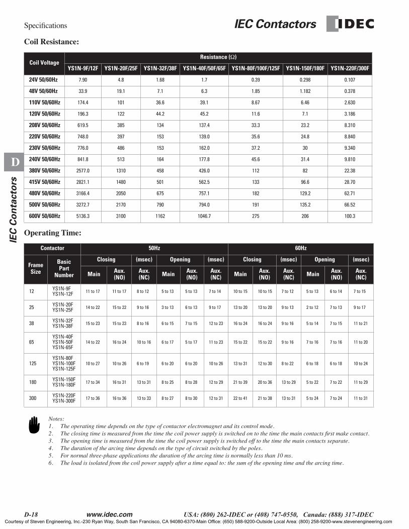
Coil Resistance:
Operating Time:
Coil VoltageResistance (Ω)
YS1N-9F/12F YS1N-20F/25F YS1N-32F/38F YS1N-40F/50F/65F YS1N-80F/100F/125F YS1N-150F/180F YS1N-220F/300F
24V 50/60Hz 7.90 4.8 1.68 1.7 0.39 0.298 0.107
48V 50/60Hz 33.9 19.1 7.1 6.3 1.85 1.182 0.378
110V 50/60Hz 174.4 101 36.6 39.1 8.67 6.46 2.630
120V 50/60Hz 196.3 122 44.2 45.2 11.6 7.1 3.186
208V 50/60Hz 619.5 385 134 137.4 33.3 23.2 8.310
220V 50/60Hz 748.0 397 153 139.0 35.6 24.8 8.840
230V 50/60Hz 776.0 486 153 162.0 37.2 30 9.340
240V 50/60Hz 841.8 513 164 177.8 45.6 31.4 9.810
380V 50/60Hz 2577.0 1310 458 426.0 112 82 22.38
415V 50/60Hz 2821.1 1480 501 562.5 133 96.6 28.70
480V 50/60Hz 3166.4 2050 675 757.1 182 129.2 62.71
500V 50/60Hz 3272.7 2170 790 794.0 191 135.2 66.52
600V 50/60Hz 5136.3 3100 1162 1046.7 275 206 100.3
Contactor 50Hz 60Hz
FrameSize
BasicPart
Number
Closing (msec) Opening (msec) Closing (msec) Opening (msec)
Main Aux. (NO)
Aux. (NC) Main Aux.
(NO)Aux. (NC) Main Aux.
(NO)Aux. (NC) Main Aux.
(NO)Aux. (NC)
12 YS1N-9FYS1N-12F 11 to 17 11 to 17 8 to 12 5 to 13 5 to 13 7 to 14 10 to 15 10 to 15 7 to 12 5 to 13 6 to 14 7 to 15
25 YS1N-20FYS1N-25F 14 to 22 15 to 22 9 to 16 3 to 13 6 to 13 9 to 17 13 to 20 13 to 20 9 to 13 2 to 12 7 to 13 9 to 17
38 YS1N-32FYS1N-38F 15 to 23 15 to 23 8 to 16 6 to 15 7 to 15 12 to 23 16 to 24 16 to 24 9 to 16 5 to 14 7 to 15 11 to 21
65YS1N-40FYS1N-50FYS1N-65F
14 to 22 16 to 24 10 to 16 6 to 17 5 to 17 11 to 23 15 to 22 15 to 22 9 to 16 7 to 16 7 to 16 11 to 20
125YS1N-80FYS1N-100FYS1N-125F
10 to 27 10 to 26 6 to 19 6 to 20 6 to 20 10 to 26 13 to 31 12 to 30 8 to 22 6 to 18 6 to 18 10 to 24
180 YS1N-150FYS1N-180F 17 to 34 16 to 31 13 to 31 8 to 25 8 to 28 12 to 29 21 to 39 20 to 36 13 to 29 5 to 22 7 to 22 11 to 29
300 YS1N-220FYS1N-300F 17 to 36 16 to 36 13 to 33 8 to 27 8 to 30 12 to 31 22 to 41 21 to 38 13 to 31 5 to 24 7 to 24 11 to 31
Notes:1. The operating time depends on the type of contactor electromagnet and its control mode.2. The closing time is measured from the time the coil power supply is switched on to the time the main contacts first make contact.3. The opening time is measured from the time the coil power supply is switched off to the time the main contacts separate.4. The duration of the arcing time depends on the type of circuit switched by the poles.5. For normal three-phase applications the duration of the arcing time is normally less than 10 ms.6. The load is isolated from the coil power supply after a time equal to: the sum of the opening time and the arcing time.
Courtesy of Steven Engineering, Inc.-230 Ryan Way, South San Francisco, CA 94080-6370-Main Office: (650) 588-9200-Outside Local Area: (800) 258-9200-www.stevenengineering.com

IEC Contactors Specifications
www.idec.com USA: (800) 262-IDEC or (408) 747-0550, Canada: (888) 317-IDEC D-19
D
IEC
Co
nta
cto
rs
Contactor Circuit Supply: DC
Operating Coil Characteristics
Standard Operating Time
Operating Limited Distances
Part Number Coil Voltage(V)
Exciting Current(mA)
Pick-Up Voltage(V)
Drop-Out Voltage(V)
Coil Resistance (1/2)
Power Consumption(W)
YS3N-9FG2YS3N-12FG2
24V DC 214 to 262 10 to 15 5 to 10 102 5.1 to 6.4
48V DC 108 to 132 21 to 30 10 to 20 404 5.1 to 6.4
100V DC 51 to 64 45 to 63 21 to 40 1750 5.0 to 6.5
200V DC 26 to 33 90 to 125 43 to 80 6870 5.1 to 6.8
YS3N-20FG2YS3N-25FG2
24V DC 214 to 262 10 to 15 5 to 10 102 5.1 to 6.4
48V DC 108 to 132 21 to 30 10 to 20 404 5.1 to 6.4
100V DC 51 to 64 45 to 63 21 to 40 1750 5.0 to 6.5
200V DC 26 to 33 90 to 125 43 to 80 6870 5.1 to 6.8
YS3N-32FG2YS3N-38FG2
24V DC 335 to 410 11 to 16 4 to 8 65.1 8.0 to 9.9
48V DC 165 to 202 23 to 32 8 to 16 264 7.8 to 9.8
100V DC 76 to 94 48 to 66 18 to 32 1190 7.5 to 9.5
200V DC 36 to 45 96 to 132 36 to 64 4970 7.0 to 9.1
YS3N-40FG2YS3N-50FG2YS3N-65FG2
24V DC 516 to 630 13 to 17 4 to 7 42.3 12.3 to 15.2
48V DC 215 to 263 27 to 33 8 to 13 203 10.3 to 12.7
100V DC 103 to 127 58 to 69 17 to 27 880 10.2 to 12.8
200V DC 53 to 66 116 to 137 35 to 53 3390 10.4 to 13.3
YS3N-80FG2YS3N-100FG2YS3N-125FG2
100V DC 19 to 24 76 to 84 43 to 54 — —
200V DC 11 to 15 133 to 144 86 to 98 — —
Part Number
Coil Applied Voltage 100%Uc
Closing Time (ms) Opening Time (ms)
Main Aux. (NO) Aux. (NC) Main Aux. (NO) Aux. (NC)
YS3N-9F 1NO 38 to 45 38 to 45 — 5 to 10 5 to 10 —
YS3N-12F 1NC 38 to 45 — 38 to 45 6 to 12 — 8 to 13
YS3N-20FG2, -25FG2 45 to 53 45 to 53 36 to 46 6 to 12 6 to 12 10 to 16
YS3N-32FG2, -38FG2 59 to 68 57 to 66 46 to 56 7 to 19 7 to 19 14 to 23
YS3N-40FG2, -50FG2, -65FG2 46 to 56 46 to 56 34 to 47 23 to 32 23 to 32 27 to 36
YS3N-80FG2, -100FG2, -125FG2 32 to 42 32 to 42 24 to 36 36 to 56 36 to 56 42 to 62
Part Number
Rated Operational Voltage 100VDC Rated Operational Voltage 200VDC
Coil Applied Voltage 100VDC Coil Applied Voltage 200VDC
Wire Sectional Area Wire Sectional Area
1.25mm2 2mm2 3.5mm2 1.25mm2 2mm2 3.5mm2
YS3N-9FG2, -12FG2 3.2 km 5.0 km 9.2 km 12.6 km 19.7 km 36.4 km
YS3N-20FG2, -25FG2 3.2 km 5.0 km 9.2 km 12.6 km 19.7 km 36.4 km
YS3N-32FG2, -38FG2 2.1 km 3.4 km 6.3 km 9.1 km 14.3 km 26.3 km
YS3N-40FG2, -50FG2, -65FG2 1.6 km 2.5 km 4.6 km 6.2 km 9.7 km 18.0 km
YS3N-80FG2, -100FG2, -125FG2 0.136 km 0.213 km 0.392 km 0.507 km 0.794 km 1.46 km
Courtesy of Steven Engineering, Inc.-230 Ryan Way, South San Francisco, CA 94080-6370-Main Office: (650) 588-9200-Outside Local Area: (800) 258-9200-www.stevenengineering.com

Specifications IEC Contactors
D-20 www.idec.com USA: (800) 262-IDEC or (408) 747-0550, Canada: (888) 317-IDEC
D
IEC
Co
nta
cto
rs
Electrical Life Curves
Electrical Life Curves
Fig.1 Utilization Category AC3
Control of three-phase squirrel cage motors switching off during runningThe breaking current in AC3, Ic, is equal to Ie. (le= rated operational current of the motor)
10
543
2
1
1 2 3 4 5 10 20 30 40 509 12 18 25 65 105 125 180 209
0.50.40.3
0.2
Millionsof OperatingCycles
Breaking current Ic (A)
Power rating in kW - 50 Hz category AC3
220V
380V
440V
0.55 0.75 1.5 2.2 5.5 7.5 11 15 22 30 90 140 220 280250
37 45 55 6518.54
YS
1N-9
F
YS
1N-1
2F
YS
1N-2
0F
YS
1N-5
0F
YS
1N-6
5F
YS
1N-8
0F
YS
1N-1
00F
YS
1N-1
25F
YS
1N-1
50F
YS
1N-1
80F
YS
1N-2
20F
YS
1N-3
00F
YS
1N-3
8F,-
40F
AC3 Ue < 440V
0.55 0.75 1.5 2.2 5.5 7.5 11 15 18.5 22 30 37 55 75 110 160 200 250 4504
0.55 0.75 1.5 5.5 7.5 11 15 55 75 90 132 200 280 42522 30 3718.52.2 4
100 150 200 300 400 500 1000Y
S1N
-25F
YS
1N-3
2F
Control of three-phase squirrel cage motors switching off with locked rotorThe breaking current in AC4, Ic, is equal to 6 x Ie. (Ie = rated operational current of the motor)
Fig. 2 Utilization Category AC4
10 20 30 4051 69
1
0.50.40.3
0.2
0.1
0.050.040.03
0.02
0.01
Millionsof OperatingCycles
Breaking current Ic (A)
YS
1N-9
F
YS
1N-1
2F
YS
1N-2
0F
YS
1N-5
0F
YS
1N-6
5F
YS
1N-8
0F
YS
1N-1
00F
YS
1N-1
25F
YS
1N-1
50F
YS
1N-1
80F
YS
1N-2
20F
YS
1N-3
00F
YS
1N-3
8F,-
40F
AC4 380V < Ue ≤440V
50 100 500 1000 2000 3000 4000 5000200 300 400102 132 180 234 360 510 702 882 1454 2850
111 272 588 1020 1998
YS
1N-2
5F
YS
1N-3
2F
Courtesy of Steven Engineering, Inc.-230 Ryan Way, South San Francisco, CA 94080-6370-Main Office: (650) 588-9200-Outside Local Area: (800) 258-9200-www.stevenengineering.com
IEC Contactors Specifications
www.idec.com USA: (800) 262-IDEC or (408) 747-0550, Canada: (888) 317-IDEC D-21
D
IEC
Co
nta
cto
rs
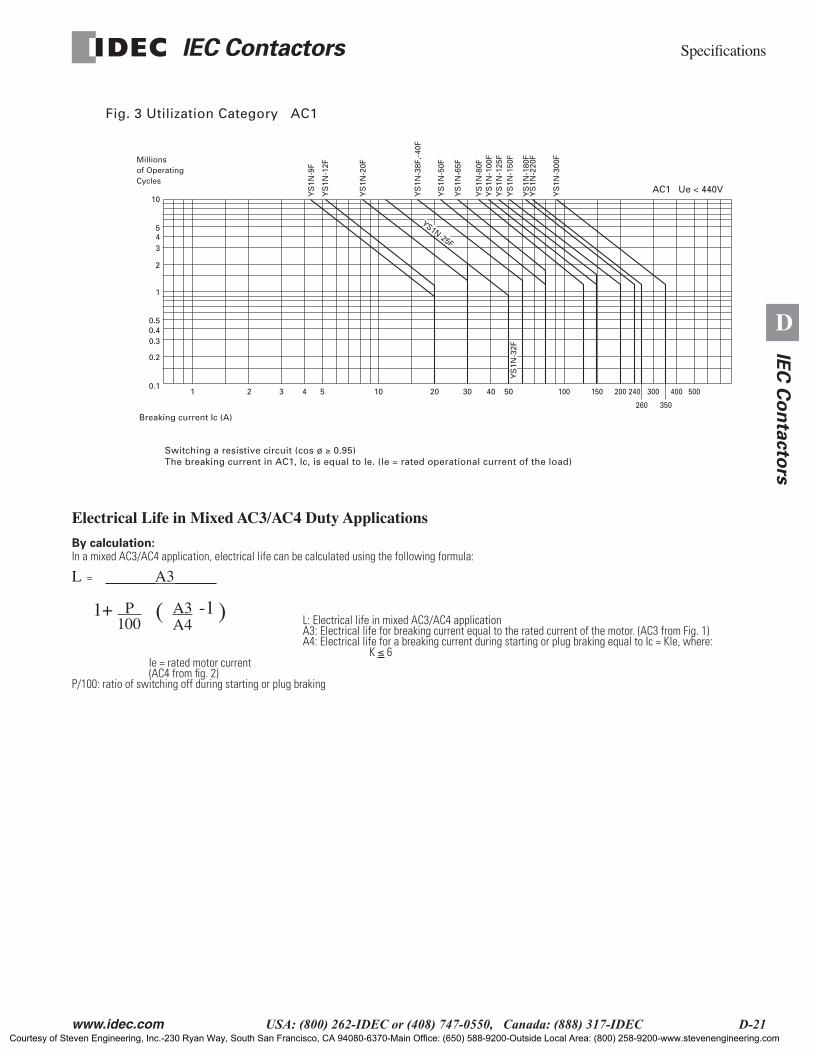
Electrical Life in Mixed AC3/AC4 Duty Applications
By calculation:In a mixed AC3/AC4 application, electrical life can be calculated using the following formula:
L = A3
L: Electrical life in mixed AC3/AC4 applicationA3: Electrical life for breaking current equal to the rated current of the motor. (AC3 from Fig. 1)A4: Electrical life for a breaking current during starting or plug braking equal to Ic = Kle, where: K ≤ 6
Ie = rated motor current (AC4 from fig. 2)P/100: ratio of switching off during starting or plug braking
Fig. 3 Utilization Category AC1
Switching a resistive circuit (cos ø ≥ 0.95)The breaking current in AC1, Ic, is equal to Ie. (le = rated operational current of the load)
1 2 3 4 5 10 20 30 40 50 100 200 300 400 500240
260 350
150
10
543
2
1
0.50.40.3
0.2
0.1
Millionsof OperatingCycles
Breaking current Ic (A)
YS
1N-9
F
YS
1N-1
2F
YS
1N-2
0F
YS
1N-5
0F
YS
1N-6
5F
YS
1N-8
0FY
S1N
-100
FY
S1N
-125
FY
S1N
-150
F
YS
1N-1
80F
YS
1N-2
20F
YS
1N-3
00F
YS
1N-3
8F,-
40F
AC1 Ue < 440V
YS1N-25F
YS
1N-3
2F
1+ ( )-1100 A4 P A3
Courtesy of Steven Engineering, Inc.-230 Ryan Way, South San Francisco, CA 94080-6370-Main Office: (650) 588-9200-Outside Local Area: (800) 258-9200-www.stevenengineering.com
Specifications IEC Contactors
D-22 www.idec.com USA: (800) 262-IDEC or (408) 747-0550, Canada: (888) 317-IDEC
D
IEC
Co
nta
cto
rs
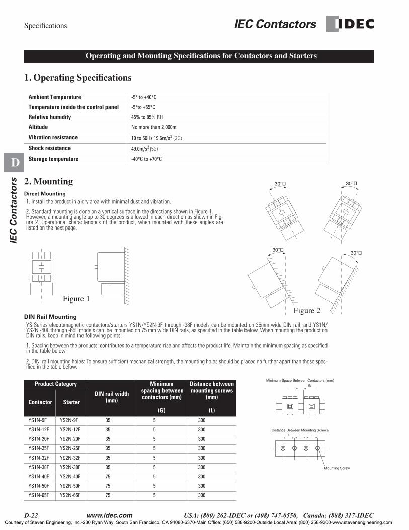
1. Operating Specifications
2. MountingDirect Mounting
DIN Rail Mounting
Ambient Temperature -5° to +40°C
Temperature inside the control panel -5°to +55°C
Relative humidity 45% to 85% RH
Altitude No more than 2,000m
Vibration resistance 10 to 50Hz 19.6m/s2 (2G)
Shock resistance 49.0m/s2 (5G)
Storage temperature -40°C to +70°C
1. Install the product in a dry area with minimal dust and vibration.
2. Standard mounting is done on a vertical surface in the directions shown in Figure 1. However, a mounting angle up to 30 degrees is allowed in each direction as shown in Fig-ure 2. Operational characteristics of the product, when mounted with these angles arelisted on the next page.
YS Series electromagnetic contactors/starters YS1N/YS2N-9F through -38F models can be mounted on 35mm wide DIN rail, and YS1N/YS2N -40F through -65F models can be mounted on 75 mm wide DIN rails, as specified in the table below. When mounting the product onDIN rails, keep in mind the following points:
1. Spacing between the products: contributes to a temperature rise and affects the product life. Maintain the minimum spacing as specifiedin the table below
2. DIN rail mounting holes: To ensure sufficient mechanical strength, the mounting holes should be placed no further apart than those spec-ified in the table below.
Product Category
DIN rail width (mm)
Minimum spacing between contactors (mm)
(G)
Distance between mounting screws
(mm)
(L)Contactor Starter
YS1N-9F YS2N-9F 35 5 300
YS1N-12F YS2N-12F 35 5 300
YS1N-20F YS2N-20F 35 5 300
YS1N-25F YS2N-25F 35 5 300
YS1N-32F YS2N-32F 35 5 300
YS1N-38F YS2N-38F 35 5 300
YS1N-40F YS2N-40F 75 5 300
YS1N-50F YS2N-50F 75 5 300
YS1N-65F YS2N-65F 75 5 300
Operating and Mounting Specifications for Contactors and Starters
30° 30°
30°30°
Figure 2
Figure 1
L L L
G
Mounting Screw
Distance Between Mounting Screws
Minimum Space Between Contactors (mm)
Courtesy of Steven Engineering, Inc.-230 Ryan Way, South San Francisco, CA 94080-6370-Main Office: (650) 588-9200-Outside Local Area: (800) 258-9200-www.stevenengineering.com
IEC Contactors Specifications
www.idec.com USA: (800) 262-IDEC or (408) 747-0550, Canada: (888) 317-IDEC D-23
D
IEC
Co
nta
cto
rs
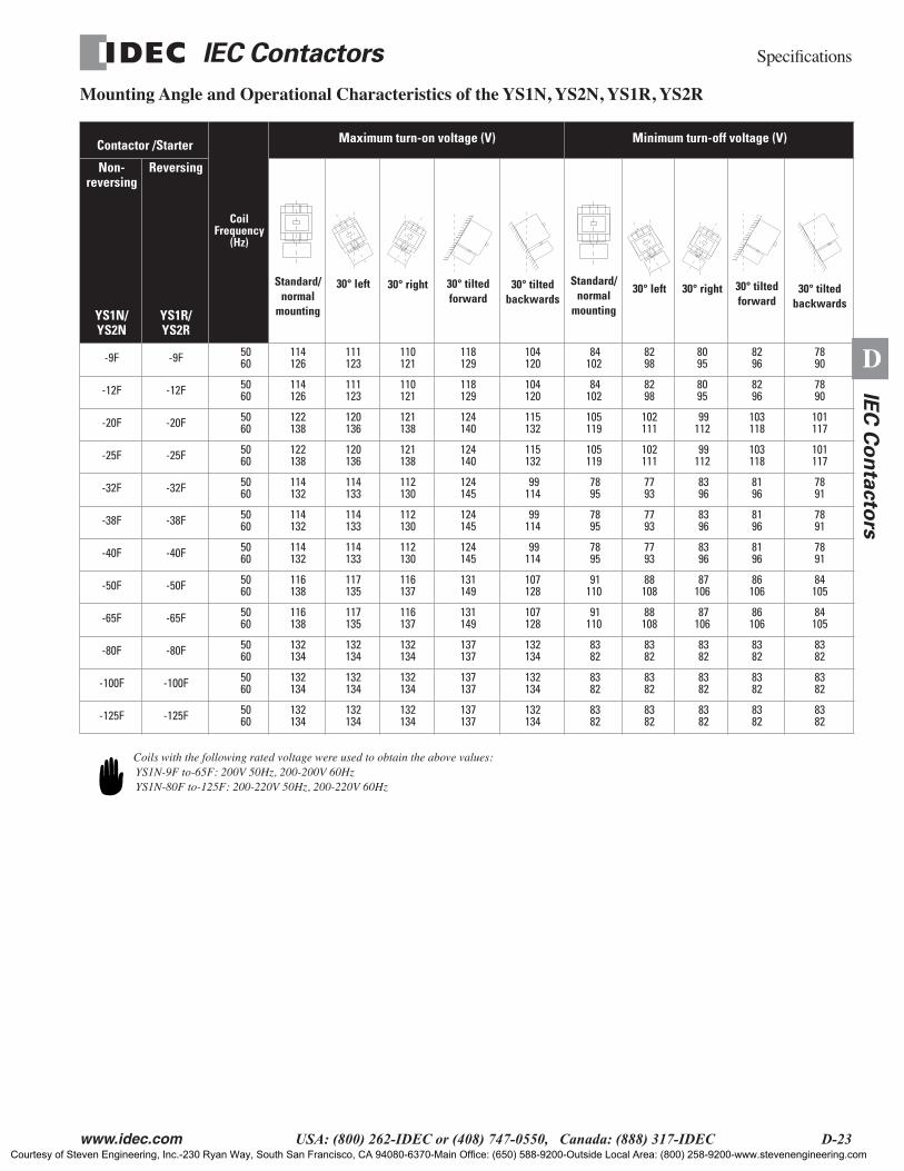
Mounting Angle and Operational Characteristics of the YS1N, YS2N, YS1R, YS2R
Coils with the following rated voltage were used to obtain the above values: YS1N-9F to-65F: 200V 50Hz, 200-200V 60Hz YS1N-80F to-125F: 200-220V 50Hz, 200-220V 60Hz
Contactor /Starter
CoilFrequency
(Hz)
Maximum turn-on voltage (V) Minimum turn-off voltage (V)
Non-reversing
YS1N/YS2N
Reversing
YS1R/YS2R
Standard/normal
mounting
30° left 30° right 30° tilted forward
30° tilted backwards
Standard/normal
mounting
30° left 30° right 30° tilted forward
30° tilted backwards
-9F -9F 50 60
114126
111123
110121
118129
104120
84102
8298
8095
8296
7890
-12F -12F 50 60
114126
111123
110121
118129
104120
84102
8298
8095
8296
7890
-20F -20F 50 60
122138
120136
121138
124140
115132
105119
102111
99112
103118
101117
-25F -25F 50 60
122138
120136
121138
124140
115132
105119
102111
99112
103118
101117
-32F -32F 50 60
114132
114133
112130
124145
99114
78 95
7793
83 96
8196
7891
-38F -38F 50 60
114132
114133
112130
124145
99114
78 95
7793
83 96
8196
7891
-40F -40F 50 60
114132
114133
112130
124145
99114
78 95
7793
83 96
8196
7891
-50F -50F 50 60
116138
117135
116137
131149
107128
91110
88108
87106
86106
84105
-65F -65F 50 60
116138
117135
116137
131149
107128
91110
88108
87106
86106
84105
-80F -80F 50 60
132134
132134
132134
137137
132134
83 82
8382
83 82
8382
8382
-100F -100F 50 60
132134
132134
132134
137137
132134
83 82
8382
83 82
8382
8382
-125F -125F 50 60
132134
132134
132134
137137
132134
83 82
8382
83 82
8382
8382
Courtesy of Steven Engineering, Inc.-230 Ryan Way, South San Francisco, CA 94080-6370-Main Office: (650) 588-9200-Outside Local Area: (800) 258-9200-www.stevenengineering.com
Specifications IEC Contactors
D-24 www.idec.com USA: (800) 262-IDEC or (408) 747-0550, Canada: (888) 317-IDEC
D
IEC
Co
nta
cto
rs
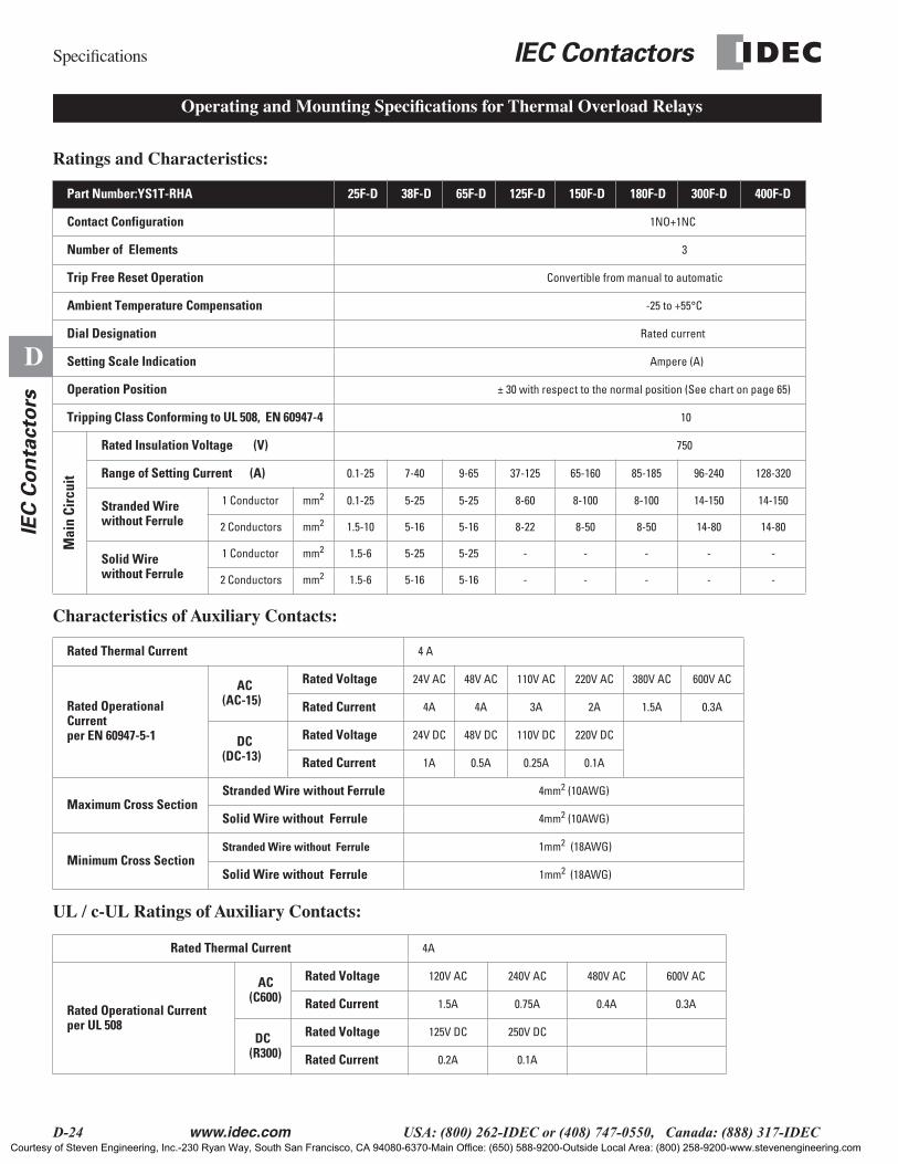
Ratings and Characteristics:
Characteristics of Auxiliary Contacts:
UL / c-UL Ratings of Auxiliary Contacts:
Part Number:YS1T-RHA 25F-D 38F-D 65F-D 125F-D 150F-D 180F-D 300F-D 400F-D
Contact Configuration 1NO+1NC
Number of Elements 3
Trip Free Reset Operation Convertible from manual to automatic
Ambient Temperature Compensation -25 to +55°C
Dial Designation Rated current
Setting Scale Indication Ampere (A)
Operation Position ± 30 with respect to the normal position (See chart on page 65)
Tripping Class Conforming to UL 508, EN 60947-4 10
Mai
n Ci
rcui
t
Rated Insulation Voltage (V) 750
Range of Setting Current (A) 0.1-25 7-40 9-65 37-125 65-160 85-185 96-240 128-320
Stranded Wire without Ferrule
1 Conductor mm2 0.1-25 5-25 5-25 8-60 8-100 8-100 14-150 14-150
2 Conductors mm2 1.5-10 5-16 5-16 8-22 8-50 8-50 14-80 14-80
Solid Wire without Ferrule
1 Conductor mm2 1.5-6 5-25 5-25 - - - - -
2 Conductors mm2 1.5-6 5-16 5-16 - - - - -
Rated Thermal Current 4 A
Rated OperationalCurrent per EN 60947-5-1
AC(AC-15)
Rated Voltage 24V AC 48V AC 110V AC 220V AC 380V AC 600V AC
Rated Current 4A 4A 3A 2A 1.5A 0.3A
DC(DC-13)
Rated Voltage 24V DC 48V DC 110V DC 220V DC
Rated Current 1A 0.5A 0.25A 0.1A
Maximum Cross SectionStranded Wire without Ferrule 4mm2 (10AWG)
Solid Wire without Ferrule 4mm2 (10AWG)
Minimum Cross SectionStranded Wire without Ferrule 1mm2 (18AWG)
Solid Wire without Ferrule 1mm2 (18AWG)
Rated Thermal Current 4A
Rated Operational Currentper UL 508
AC(C600)
Rated Voltage 120V AC 240V AC 480V AC 600V AC
Rated Current 1.5A 0.75A 0.4A 0.3A
DC(R300)
Rated Voltage 125V DC 250V DC
Rated Current 0.2A 0.1A
Operating and Mounting Specifications for Thermal Overload Relays
Courtesy of Steven Engineering, Inc.-230 Ryan Way, South San Francisco, CA 94080-6370-Main Office: (650) 588-9200-Outside Local Area: (800) 258-9200-www.stevenengineering.com
IEC Contactors Specifications
www.idec.com USA: (800) 262-IDEC or (408) 747-0550, Canada: (888) 317-IDEC D-25
D
IEC
Co
nta
cto
rs
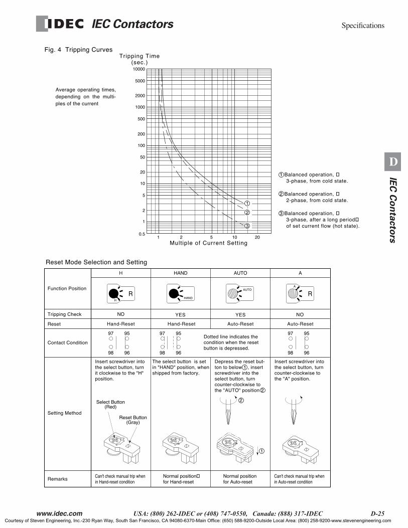
Reset Mode Selection and Setting
Contact Condition
Remarks
Setting Method
Function Position
Tripping Check
Reset
H
RHAND
AUTOA
R
Depress the reset but-ton to below 1 , insert screwdriver into the select button, turn counter-clockwise to the "AUTO" position 2
Insert screwdriver into the select button, turn counter-clockwise to the "A" position.
Insert screwdriver into the select button, turn it clockwise to the "H" position.
Can't check manual trip when in Hand-reset condition
Normal positionfor Hand-reset
Normal positionfor Auto-reset
Can't check manual trip when in Auto-reset condition
The select button is set in "HAND" position, when shipped from factory.
Dotted line indicates the condition when the reset button is depressed.
2
1
Select Button(Red)
Reset Button(Gray)
97
98
95
96
97
98
95
96
97
98
95
96
H
Hand-Reset Hand-Reset
NO
Auto-Reset
YESYES
Auto-Reset
HAND AUTO A
NO
Fig. 4 Tripping Curves
Average operating times, depending on the multi-ples of the current
10000
5000
1000
2000
500
100
200
50
10
20
5
1
2
0.51 2 5 10 20
Multiple of Current Setting
Tripping Time(sec.)
1
2
3
1 Balanced operation, 3-phase, from cold state.
2 Balanced operation, 2-phase, from cold state.
3 Balanced operation, 3-phase, after a long period of set current flow (hot state).
Courtesy of Steven Engineering, Inc.-230 Ryan Way, South San Francisco, CA 94080-6370-Main Office: (650) 588-9200-Outside Local Area: (800) 258-9200-www.stevenengineering.com

Specifications IEC Contactors
D-26 www.idec.com USA: (800) 262-IDEC or (408) 747-0550, Canada: (888) 317-IDEC
D
IEC
Co
nta
cto
rs
Operating Time Characteristics of Thermal Overload Relays
YS1T-RHA38F, YS1T-RHA65F YS1T-RHA25F
YS1T-RHA125F
1000
500
100
50
10
5
1
0.5
0.1100 200 300 400 500 600 700 800
Current (% of Steady State)
Op
era
tin
g T
ime
(In
Se
con
ds)
1000
500
100
50
10
5
1
0.5
0.1100 200 300 400 500 600 700 800
Current (% of Steady State)
Op
era
tin
g T
ime
(In
Se
con
ds)
YS1T-RHA150F
1000
500
100
50
10
5
1
0.5
0.1100 200 300 400 500 600 700 800
Current (% of Steady State)
Op
era
tin
g T
ime
(In
Se
con
ds)
Sta
rtin
g C
ha
ract
eri
stic
Lo
ad
Ch
ara
cte
rist
ics
Sta
rtin
g C
ha
ract
eri
stic
Lo
ad
Ch
ara
cte
rist
ics
Sta
rtin
g C
ha
ract
eri
stic
Lo
ad
Ch
ara
cte
rist
ics
1000
500
100
50
10
5
1
0.5
0.1100 200 300 400 500 600 700 800
Current (% of Steady State)
Op
era
tin
g T
ime
(In
Se
con
ds)
Sta
rtin
g C
ha
ract
eri
stic
Lo
ad
Ch
ara
cte
rist
ics
Courtesy of Steven Engineering, Inc.-230 Ryan Way, South San Francisco, CA 94080-6370-Main Office: (650) 588-9200-Outside Local Area: (800) 258-9200-www.stevenengineering.com
IEC Contactors Specifications
www.idec.com USA: (800) 262-IDEC or (408) 747-0550, Canada: (888) 317-IDEC D-27
D
IEC
Co
nta
cto
rs
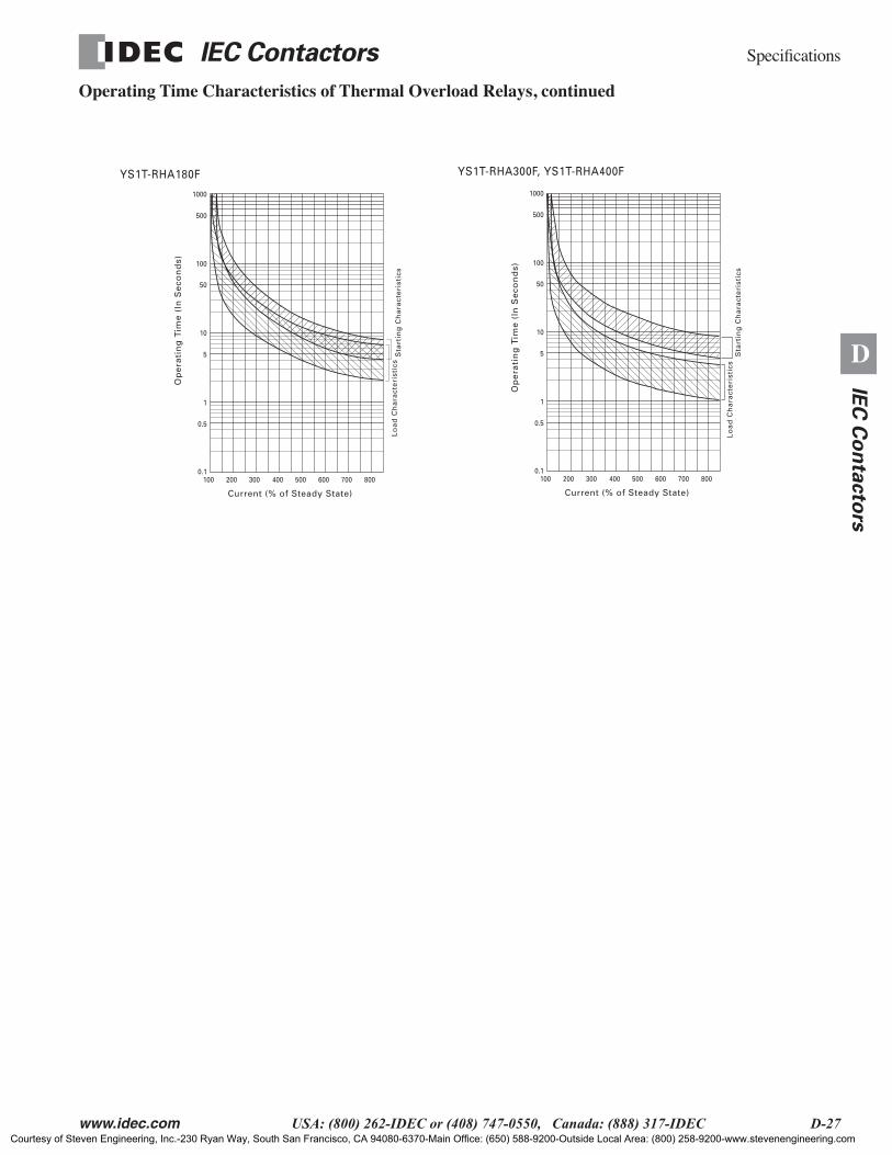
Operating Time Characteristics of Thermal Overload Relays, continued
1000
500
100
50
10
5
1
0.5
0.1100 200 300 400 500 600 700 800
Current (% of Steady State)
Op
era
tin
g T
ime
(In
Se
con
ds)
Sta
rtin
g C
ha
ract
eri
stic
sL
oa
d C
ha
ract
eri
stic
s
YS1T-RHA180F
1000
500
100
50
10
5
1
0.5
0.1100 200 300 400 500 600 700 800
Current (% of Steady State)
Op
era
tin
g T
ime
(In
Se
con
ds)
Sta
rtin
g C
ha
ract
eri
stic
sL
oa
d C
ha
ract
eri
stic
s
YS1T-RHA300F, YS1T-RHA400F
Courtesy of Steven Engineering, Inc.-230 Ryan Way, South San Francisco, CA 94080-6370-Main Office: (650) 588-9200-Outside Local Area: (800) 258-9200-www.stevenengineering.com
Specifications IEC Contactors
D-28 www.idec.com USA: (800) 262-IDEC or (408) 747-0550, Canada: (888) 317-IDEC
D
IEC
Co
nta
cto
rs
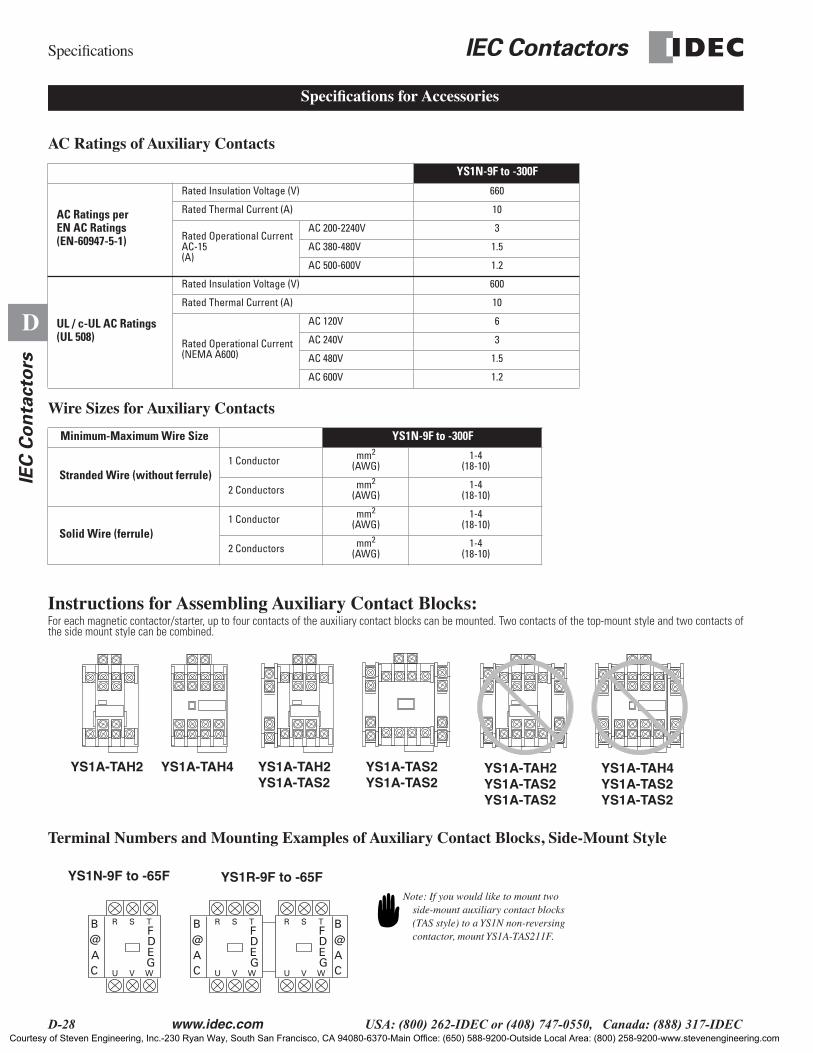
AC Ratings of Auxiliary Contacts
Wire Sizes for Auxiliary Contacts
Instructions for Assembling Auxiliary Contact Blocks:For each magnetic contactor/starter, up to four contacts of the auxiliary contact blocks can be mounted. Two contacts of the top-mount style and two contacts ofthe side mount style can be combined.
Terminal Numbers and Mounting Examples of Auxiliary Contact Blocks, Side-Mount Style
YS1N-9F to -300F
AC Ratings per EN AC Ratings (EN-60947-5-1)
Rated Insulation Voltage (V) 660
Rated Thermal Current (A) 10
Rated Operational CurrentAC-15(A)
AC 200-2240V 3
AC 380-480V 1.5
AC 500-600V 1.2
UL / c-UL AC Ratings (UL 508)
Rated Insulation Voltage (V) 600
Rated Thermal Current (A) 10
Rated Operational Current(NEMA A600)
AC 120V 6
AC 240V 3
AC 480V 1.5
AC 600V 1.2
Minimum-Maximum Wire Size YS1N-9F to -300F
Stranded Wire (without ferrule)1 Conductor mm2
(AWG)1-4
(18-10)
2 Conductors mm2 (AWG)
1-4(18-10)
Solid Wire (ferrule)1 Conductor mm2
(AWG)1-4
(18-10)
2 Conductors mm2 (AWG)
1-4(18-10)
Specifications for Accessories
YS1A-TAH2 YS1A-TAH4 YS1A-TAH2YS1A-TAS2
YS1A-TAS2YS1A-TAS2
YS1A-TAH2YS1A-TAS2YS1A-TAS2
YS1A-TAH4YS1A-TAS2YS1A-TAS2
R
U V W
S T
D
B@AC
E
R
U V W
S T
DF F
B@AC
EG
R
U V W
S T
D
C
E
F
G G
B@A
YS1N-9F to -65F YS1R-9F to -65FNote: If you would like to mount two
side-mount auxiliary contact blocks (TAS style) to a YS1N non-reversing contactor, mount YS1A-TAS211F.
Courtesy of Steven Engineering, Inc.-230 Ryan Way, South San Francisco, CA 94080-6370-Main Office: (650) 588-9200-Outside Local Area: (800) 258-9200-www.stevenengineering.com

IEC Contactors Specifications
www.idec.com USA: (800) 262-IDEC or (408) 747-0550, Canada: (888) 317-IDEC D-29
D
IEC
Co
nta
cto
rs
Mounting and Removing Auxiliary Contact Block on the Contactor
Top Mount Style
Removal Procedure
Side-Mount Style
DIN rail Mounting
Removal Procedure
1. Position the contactor and the auxiliary contact block in thesame direction.
2. Insert the auxiliary contact block into the area of the top ofthe contactor. Slide the auxiliary contact until it bottoms (Donot force.) Make sure that the locking hook is locked into posi-tion as shown
While lightly lifting the locking hook with your finger, slide theauxiliary contact unit out.
1. Contactor plunger
2. Inside this area, there are locking hooks (upper and lower areas)
1. Make sure that the auxiliary contact block (right or left side) and the terminalnumbers on the contactor are in the same direction.
2. Push the plunger of the contactor downwards approximately 2mm. While hold-ing the plunger in this manner, insert the white protruding portion of the auxiliarycontact block into the square groove of the side of the contactor. Make sure thatthe locking hook is locked into position.
Hold the auxiliary contact block and pull it off.
Courtesy of Steven Engineering, Inc.-230 Ryan Way, South San Francisco, CA 94080-6370-Main Office: (650) 588-9200-Outside Local Area: (800) 258-9200-www.stevenengineering.com
Specifications IEC Contactors
D-30 www.idec.com USA: (800) 262-IDEC or (408) 747-0550, Canada: (888) 317-IDEC
D
IEC
Co
nta
cto
rs
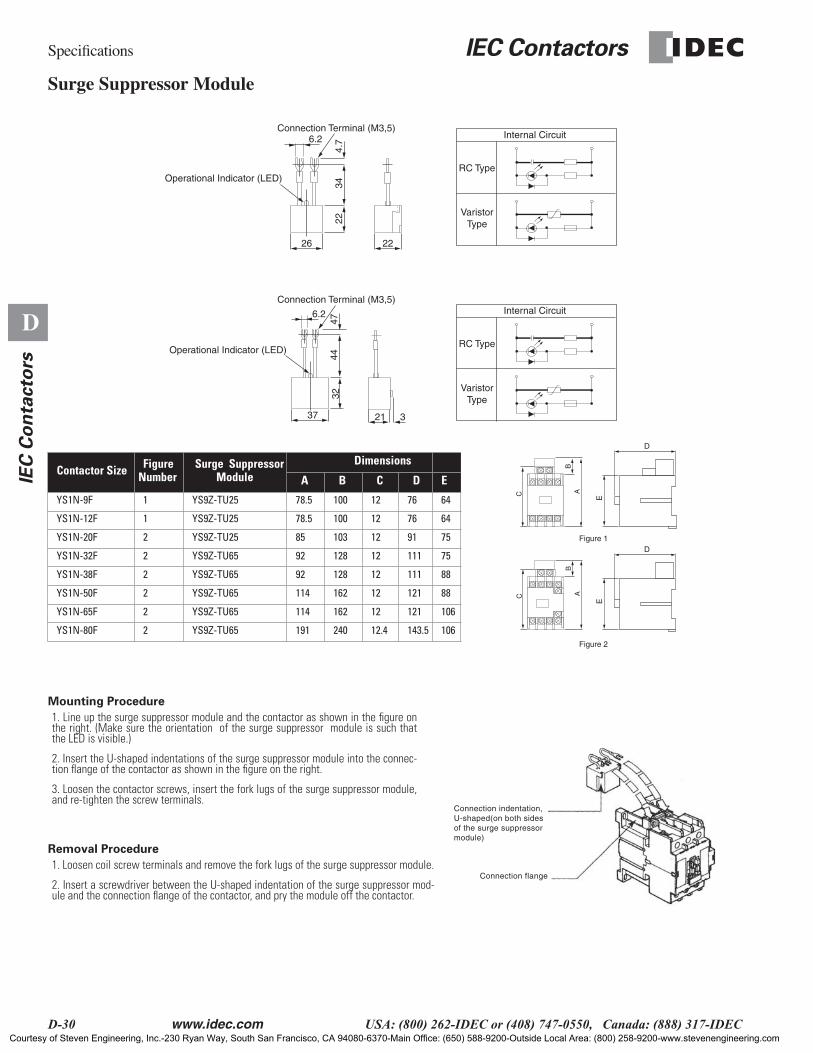
Surge Suppressor Module
Mounting Procedure
Removal Procedure
Contactor Size Figure Number
Surge Suppressor Module
Dimensions
A B C D E
YS1N-9F 1 YS9Z-TU25 78.5 100 12 76 64
YS1N-12F 1 YS9Z-TU25 78.5 100 12 76 64
YS1N-20F 2 YS9Z-TU25 85 103 12 91 75
YS1N-32F 2 YS9Z-TU65 92 128 12 111 75
YS1N-38F 2 YS9Z-TU65 92 128 12 111 88
YS1N-50F 2 YS9Z-TU65 114 162 12 121 88
YS1N-65F 2 YS9Z-TU65 114 162 12 121 106
YS1N-80F 2 YS9Z-TU65 191 240 12.4 143.5 106
1. Line up the surge suppressor module and the contactor as shown in the figure onthe right. (Make sure the orientation of the surge suppressor module is such thatthe LED is visible.)
2. Insert the U-shaped indentations of the surge suppressor module into the connec-tion flange of the contactor as shown in the figure on the right.
3. Loosen the contactor screws, insert the fork lugs of the surge suppressor module,and re-tighten the screw terminals.
1. Loosen coil screw terminals and remove the fork lugs of the surge suppressor module.
2. Insert a screwdriver between the U-shaped indentation of the surge suppressor mod-ule and the connection flange of the contactor, and pry the module off the contactor.
6.2
26 22
4.7
3422
6.2
37 21 3
4447
32
Operational Indicator (LED)
Operational Indicator (LED)
Connection Terminal (M3,5)
Connection Terminal (M3,5)
Internal Circuit
RC Type
VaristorType
Internal Circuit
RC Type
VaristorType
D
E
BAC
BAC
D
E
Figure 1
Figure 2
Connection indentation,U-shaped(on both sides of the surge suppressormodule)
Connection flange
Courtesy of Steven Engineering, Inc.-230 Ryan Way, South San Francisco, CA 94080-6370-Main Office: (650) 588-9200-Outside Local Area: (800) 258-9200-www.stevenengineering.com

IEC Contactors Specifications
www.idec.com USA: (800) 262-IDEC or (408) 747-0550, Canada: (888) 317-IDEC D-31
D
IEC
Co
nta
cto
rs
Specifications of Relay Interface Module
Relay Interface Completed Part Numbers
NOTES: Each model is identical in electrical characteristics, mounting plate sizes representing the only difference.
YS9Z-TCU500UH
Input (coil)
Rated Voltage 24V DC
Maximum Allowable Voltage 130% of rated voltage
Power Consumption 0.2W
Pick-up Voltage (at 20°C) 70% of rated voltage
Drop-out Voltage (at 20°C) 10% of rated voltage
Output (contact)
Maximum Operational Voltage 380V AC
Rated Operational Current (at 250V AC) 2A (cosø=0.4)
Thermal Current 5A
Closing Delay 3 ms
Opening Delay 1 ms
Temperature Range -20 to +55°C
Surge Suppressor Device
Maximum Operational Voltage 250V AC
Function Resistor capacitor circuit (RC)
Applicable Control Coil Voltage Range Up to 240V AC (50/60 Hz)
Product Series Applicable Contactor
Completed Part Number
Dimensions
W H D
Relay Interface ModuleYS9Z-TCU
YS1N-9FYS1N-12F YS9Z-TCU500UH12 49 125 76
YS1N-20FYS1N-25F YS9Z-TCU500UH25 49 135 91
YS1N-32FYS1N-38F YS9Z-TCU500UH38 58 140 111
YS1N-40FYS1N-50FYS1N-65F
YS9Z-TCU500UH65 75 160 121
YS1N-80FYS1N-100FYS1N-125F
YS9Z-TCU500UH125 100 187 133
YS1N-150FYS1N-180F YS9Z-TCU500UH180 130 225 158
YS1N-220FYS1N-300F YS9Z-TCU500UH300 146 260 184
CONNECTION DIAGRAM AND INTERNAL CIRCUIT OF THE RELAY INTERFACE MODULE
E
RC
(+) e
(–) f
c
d aRY MC
b A2
A1
CONTACTORPLC (RELAY INTERFACE MODULE)
H
W D
Courtesy of Steven Engineering, Inc.-230 Ryan Way, South San Francisco, CA 94080-6370-Main Office: (650) 588-9200-Outside Local Area: (800) 258-9200-www.stevenengineering.com
Specifications IEC Contactors
D-32 www.idec.com USA: (800) 262-IDEC or (408) 747-0550, Canada: (888) 317-IDEC
D
IEC
Co
nta
cto
rs
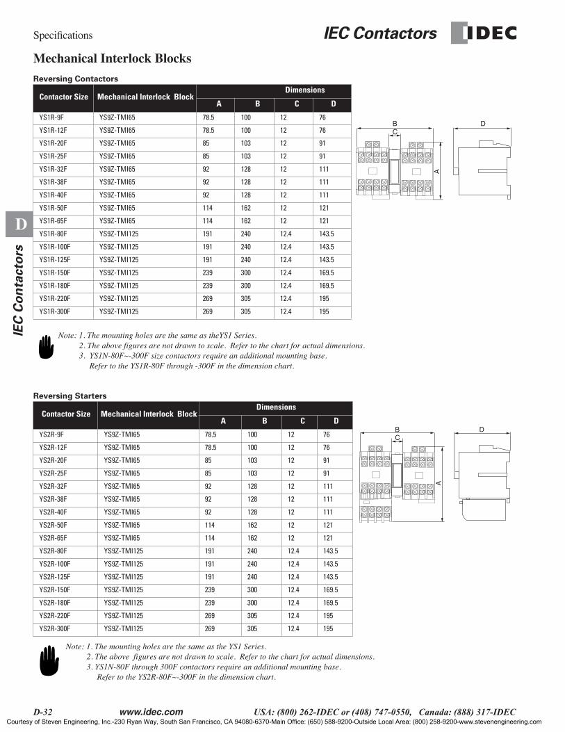
Mechanical Interlock Blocks
Reversing Contactors
Reversing Starters
Contactor Size Mechanical Interlock Block Dimensions
A B C D
YS1R-9F YS9Z-TMI65 78.5 100 12 76
YS1R-12F YS9Z-TMI65 78.5 100 12 76
YS1R-20F YS9Z-TMI65 85 103 12 91
YS1R-25F YS9Z-TMI65 85 103 12 91
YS1R-32F YS9Z-TMI65 92 128 12 111
YS1R-38F YS9Z-TMI65 92 128 12 111
YS1R-40F YS9Z-TMI65 92 128 12 111
YS1R-50F YS9Z-TMI65 114 162 12 121
YS1R-65F YS9Z-TMI65 114 162 12 121
YS1R-80F YS9Z-TMI125 191 240 12.4 143.5
YS1R-100F YS9Z-TMI125 191 240 12.4 143.5
YS1R-125F YS9Z-TMI125 191 240 12.4 143.5
YS1R-150F YS9Z-TMI125 239 300 12.4 169.5
YS1R-180F YS9Z-TMI125 239 300 12.4 169.5
YS1R-220F YS9Z-TMI125 269 305 12.4 195
YS1R-300F YS9Z-TMI125 269 305 12.4 195
Contactor Size Mechanical Interlock BlockDimensions
A B C D
YS2R-9F YS9Z-TMI65 78.5 100 12 76
YS2R-12F YS9Z-TMI65 78.5 100 12 76
YS2R-20F YS9Z-TMI65 85 103 12 91
YS2R-25F YS9Z-TMI65 85 103 12 91
YS2R-32F YS9Z-TMI65 92 128 12 111
YS2R-38F YS9Z-TMI65 92 128 12 111
YS2R-40F YS9Z-TMI65 92 128 12 111
YS2R-50F YS9Z-TMI65 114 162 12 121
YS2R-65F YS9Z-TMI65 114 162 12 121
YS2R-80F YS9Z-TMI125 191 240 12.4 143.5
YS2R-100F YS9Z-TMI125 191 240 12.4 143.5
YS2R-125F YS9Z-TMI125 191 240 12.4 143.5
YS2R-150F YS9Z-TMI125 239 300 12.4 169.5
YS2R-180F YS9Z-TMI125 239 300 12.4 169.5
YS2R-220F YS9Z-TMI125 269 305 12.4 195
YS2R-300F YS9Z-TMI125 269 305 12.4 195
BC
A
D
Note: 1. The mounting holes are the same as theYS1 Series. 2. The above figures are not drawn to scale. Refer to the chart for actual dimensions. 3. YS1N-80F~-300F size contactors require an additional mounting base. Refer to the YS1R-80F through -300F in the dimension chart.
CB D
A
Note: 1. The mounting holes are the same as the YS1 Series. 2. The above figures are not drawn to scale. Refer to the chart for actual dimensions. 3. YS1N-80F through 300F contactors require an additional mounting base. Refer to the YS2R-80F~-300F in the dimension chart.
Courtesy of Steven Engineering, Inc.-230 Ryan Way, South San Francisco, CA 94080-6370-Main Office: (650) 588-9200-Outside Local Area: (800) 258-9200-www.stevenengineering.com

IEC Contactors Specifications
www.idec.com USA: (800) 262-IDEC or (408) 747-0550, Canada: (888) 317-IDEC D-33
D
IEC
Co
nta
cto
rs
Mounting and Removing of Mechanical Interlock Block
Mounting Procedure (YS9Z-TMI65)
Removal Procedure
Mounting Procedure (YS9Z-TMI125)
Removal Procedure
1. Position the mechanical interlock block and the contactor in the same direction. (Thename plate of the mechanical interlock block should be in the same direction as thename plate of the contactor.
2. Insert the connection pins of the mechanical interlock block (located on the left andright sides of the mechanical interlock block) into the pin holes of the forward andreverse contactors (the forward contactor in the right and the reverse contactor in theleft in the picture). Carefully push the contactors towards the mechanical interlock blockto lock the entire assembly together.
3. Insert the mounting base into the bottom of the mechanical interlock block until itbottoms. (Make sure that the arrow -shaped protrusion of the mechanical interlock asfar as it will go.
1. To remove the mechanical interlock block, insert a screwdriver into the spacebetween the mechanical interlock block and the mounting base.
2. Remove the mounting base from the assembly.
3. Gently pull the forward and reverse contactors apart.
1. Position the mechanical interlock and the contactor in the same direction. (The nameplate of the mechanical interlock should be in the same direction as the name plate of thecontactor.)
2. Insert the connection pin of the mechanical interlock into the connection pin holelocated on the right side of the forward contactor. The 7 - shaped hook of the mechanicalinterlock reaches the contactor. Position the 7 - shaped hook of the mechanical interlockto match the ribbed area of the contactor and press the mechanical interlock blocktowards the forward contactor.
3. For the reverse contactor, follow the same procedure above, but insert the connectionpin of the mechanical interlock block into the pin hole located on the left side of thereverse contactor. (Note: The mounting order of the forward or the reverse contactor doesnot make a difference in the assembly procedure.)
4. After the mechanical interlock block is installed to both contactors, mount the contac-tors to the mounting base with the screws (4 screws for each contactor, total of 8 screws.)Make sure that the mechanical interlock block is completely locked to the contactors.Please note that there can be operational problems if the mechanical interlock and thecontactors are not properly locked into position.
1. Insert a screwdriver into the 7-shaped hook area between either contactor and themechanical interlock and pry out the mechanical interlock.
The arrow-shapedprotrusion of themechanical interlockgoes into this hole
Mounting base
Mechanical interlockblock
(Forward)Contactor
(Reverse)Contactor
Mounting Base
Mechanical Interlock Block
7-shaped hook
Connection pin
Connection pin hole
Courtesy of Steven Engineering, Inc.-230 Ryan Way, South San Francisco, CA 94080-6370-Main Office: (650) 588-9200-Outside Local Area: (800) 258-9200-www.stevenengineering.com
Specifications IEC Contactors
D-34 www.idec.com USA: (800) 262-IDEC or (408) 747-0550, Canada: (888) 317-IDEC
D
IEC
Co
nta
cto
rs
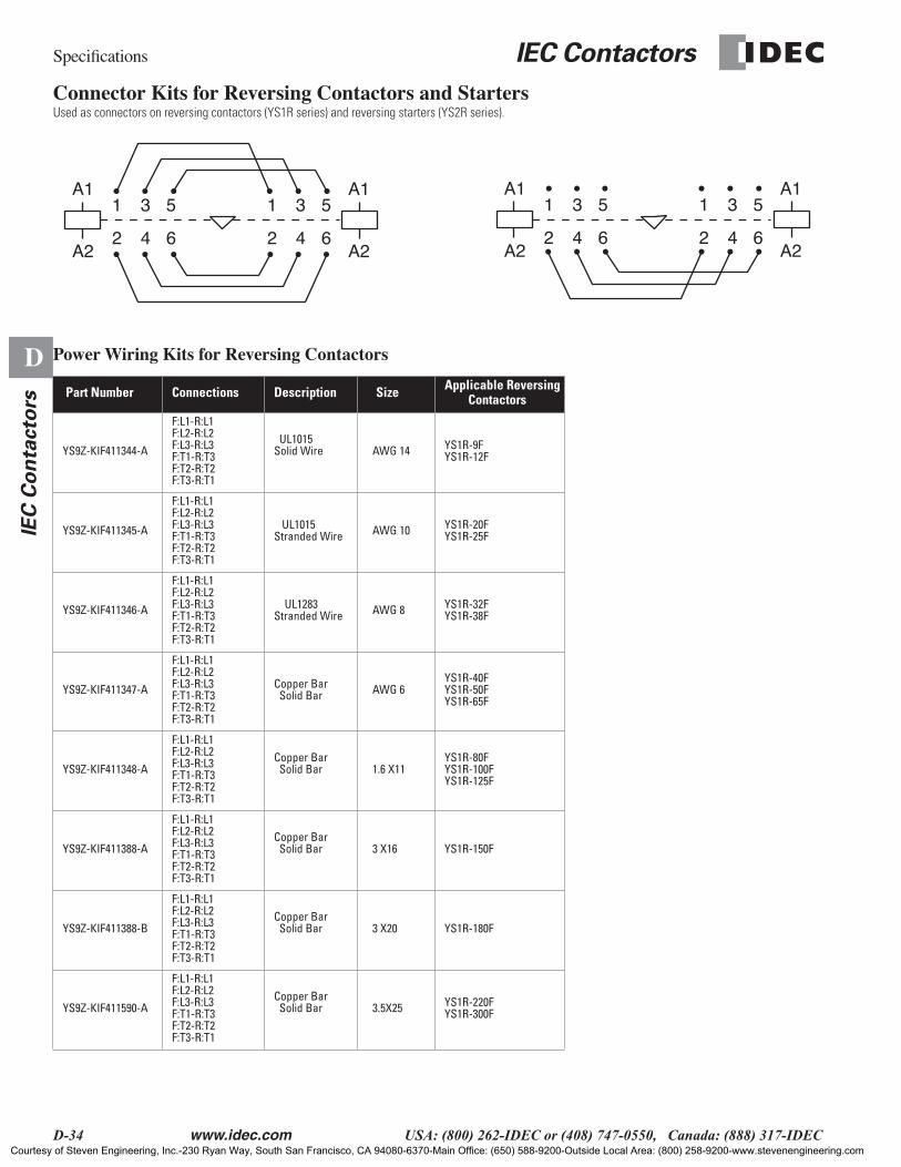
Connector Kits for Reversing Contactors and StartersUsed as connectors on reversing contactors (YS1R series) and reversing starters (YS2R series).
Power Wiring Kits for Reversing Contactors
Part Number Connections Description Size Applicable Reversing Contactors
YS9Z-KIF411344-A
F:L1-R:L1F:L2-R:L2F:L3-R:L3F:T1-R:T3F:T2-R:T2F:T3-R:T1
UL1015Solid Wire AWG 14 YS1R-9F
YS1R-12F
YS9Z-KIF411345-A
F:L1-R:L1F:L2-R:L2F:L3-R:L3F:T1-R:T3F:T2-R:T2F:T3-R:T1
UL1015Stranded Wire AWG 10 YS1R-20F
YS1R-25F
YS9Z-KIF411346-A
F:L1-R:L1F:L2-R:L2F:L3-R:L3F:T1-R:T3F:T2-R:T2F:T3-R:T1
UL1283Stranded Wire AWG 8 YS1R-32F
YS1R-38F
YS9Z-KIF411347-A
F:L1-R:L1F:L2-R:L2F:L3-R:L3F:T1-R:T3F:T2-R:T2F:T3-R:T1
Copper Bar Solid Bar AWG 6
YS1R-40FYS1R-50FYS1R-65F
YS9Z-KIF411348-A
F:L1-R:L1F:L2-R:L2F:L3-R:L3F:T1-R:T3F:T2-R:T2F:T3-R:T1
Copper Bar Solid Bar 1.6 X11
YS1R-80FYS1R-100FYS1R-125F
YS9Z-KIF411388-A
F:L1-R:L1F:L2-R:L2F:L3-R:L3F:T1-R:T3F:T2-R:T2F:T3-R:T1
Copper Bar Solid Bar 3 X16 YS1R-150F
YS9Z-KIF411388-B
F:L1-R:L1F:L2-R:L2F:L3-R:L3F:T1-R:T3F:T2-R:T2F:T3-R:T1
Copper Bar Solid Bar 3 X20 YS1R-180F
YS9Z-KIF411590-A
F:L1-R:L1F:L2-R:L2F:L3-R:L3F:T1-R:T3F:T2-R:T2F:T3-R:T1
Copper Bar Solid Bar 3.5X25 YS1R-220F
YS1R-300F
A1
A2
A1
A2
1 3 5
2 4 6
1 3 5
2 4 6
A1
A2
A1
A2
1 3 5
2 4 6
1 3 5
2 4 6
Courtesy of Steven Engineering, Inc.-230 Ryan Way, South San Francisco, CA 94080-6370-Main Office: (650) 588-9200-Outside Local Area: (800) 258-9200-www.stevenengineering.com

IEC Contactors
Dimensions
www.idec.com
USA: (800) 262-IDEC or (408) 747-0550, Canada: (888) 317-IDEC D-35
D
IEC
Co
nta
cto
rs
All Dimensions in mm.
Non-Reversing AC Contactors
Non-Reversing Contactors
YS1N-9F, YS1N-12F YS1N-40F, YS1N-50F, YS1N-65F
YS1N-80F, YS1N-100F, YS1N-125F
YS1N-150F
YS1N-20F, YS1N-25F
YS1N-32F, YS1N-38F
4412 12
(YS1A-TAS) (YS1A-TAS)
11078
.5 89(Y
S9Z
-TU
25)
(YS1A-TAH)
768
45.512 12
(YS1A-TAS) (YS1A-TAS)
124
100 30 133
141
85 97(Y
S9Z
-TU
25)
(YS1A-TAH)
918
12 12 15475
(YS1A-TAS) (YS1A-TAS) (YS1A-TAH)
114
119.
5
(YS
9Z-T
U65
)
1219
5812 12
(YS1A-TAS) (YS1A-TAS)
143.5
92
101.
5(Y
S9Z
-TU
65)
(YS1A-TAH)
1119
130 188
180
158
Courtesy of Steven Engineering, Inc.-230 Ryan Way, South San Francisco, CA 94080-6370-Main Office: (650) 588-9200-Outside Local Area: (800) 258-9200-www.stevenengineering.com

Dimensions
IEC Contactors
D-36
www.idec.com
USA: (800) 262-IDEC or (408) 747-0550, Canada: (888) 317-IDEC
D
IE
C C
on
tacto
rs
Non-Reversing Contactors
YS1N-180F YS1N-220F, YS1N-300F
130 188
180
158
146 234
184
210
Non-Reversing Contactors DC Operated
YS3N-9FG2, YS3N-12FG2 YS3N-80FG, YS3N-100FG, YS3N-125FG
YS3N-20FG2, YS3N-25FG2 YS3N-32FG2, YS3N-38FG2
YS3N-40FG2, YS3N-50FG2, YS3N-65FG2
44
107.5
81.4
8
100 30 133
141
86.5
92
114
45.5 58
75
118.5138
1609
98
Non-Reversing DC Contactors
Courtesy of Steven Engineering, Inc.-230 Ryan Way, South San Francisco, CA 94080-6370-Main Office: (650) 588-9200-Outside Local Area: (800) 258-9200-www.stevenengineering.com

IEC Contactors
Dimensions
www.idec.com
USA: (800) 262-IDEC or (408) 747-0550, Canada: (888) 317-IDEC D-37
D
IEC
Co
nta
cto
rs
Non-Reversing AC Starters
Non-Reversing Starters
YS2N-9F, YS2N-12F YS2N-40F, YS2N-50F, YS2N-65F
YS2N-80F, YS2N-100F, YS2N-125F
YS2N-150F
YS2N-20F, YS2N-25F
YS2N-32F, YS2N-38F
45 90.5
128
7644
92.545
100 11722
4
133.
5
9145.5
10556
168
121
133100
75
56 106
150
11158
100 122
259.
5
158130
Courtesy of Steven Engineering, Inc.-230 Ryan Way, South San Francisco, CA 94080-6370-Main Office: (650) 588-9200-Outside Local Area: (800) 258-9200-www.stevenengineering.com
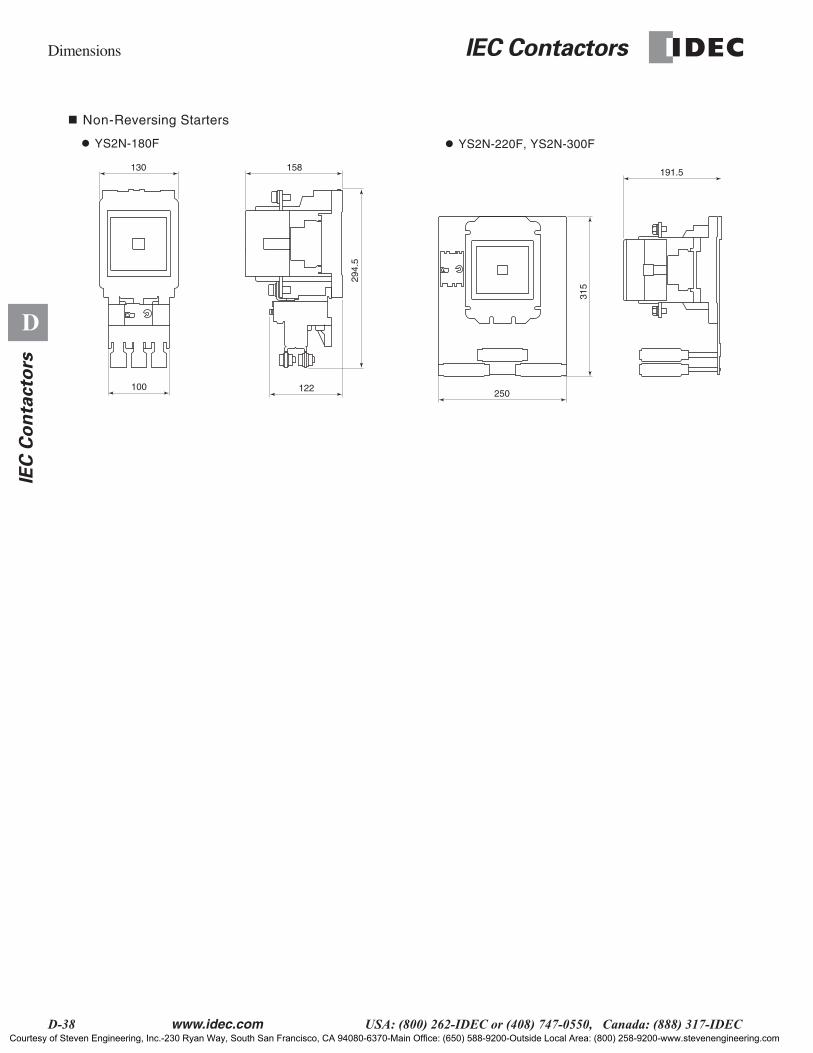
Dimensions
IEC Contactors
D-38
www.idec.com
USA: (800) 262-IDEC or (408) 747-0550, Canada: (888) 317-IDEC
D
IE
C C
on
tacto
rs
Non-Reversing Starters
YS2N-180F YS2N-220F, YS2N-300F
250
191.5
315
100 122
294.
5
158130
Courtesy of Steven Engineering, Inc.-230 Ryan Way, South San Francisco, CA 94080-6370-Main Office: (650) 588-9200-Outside Local Area: (800) 258-9200-www.stevenengineering.com
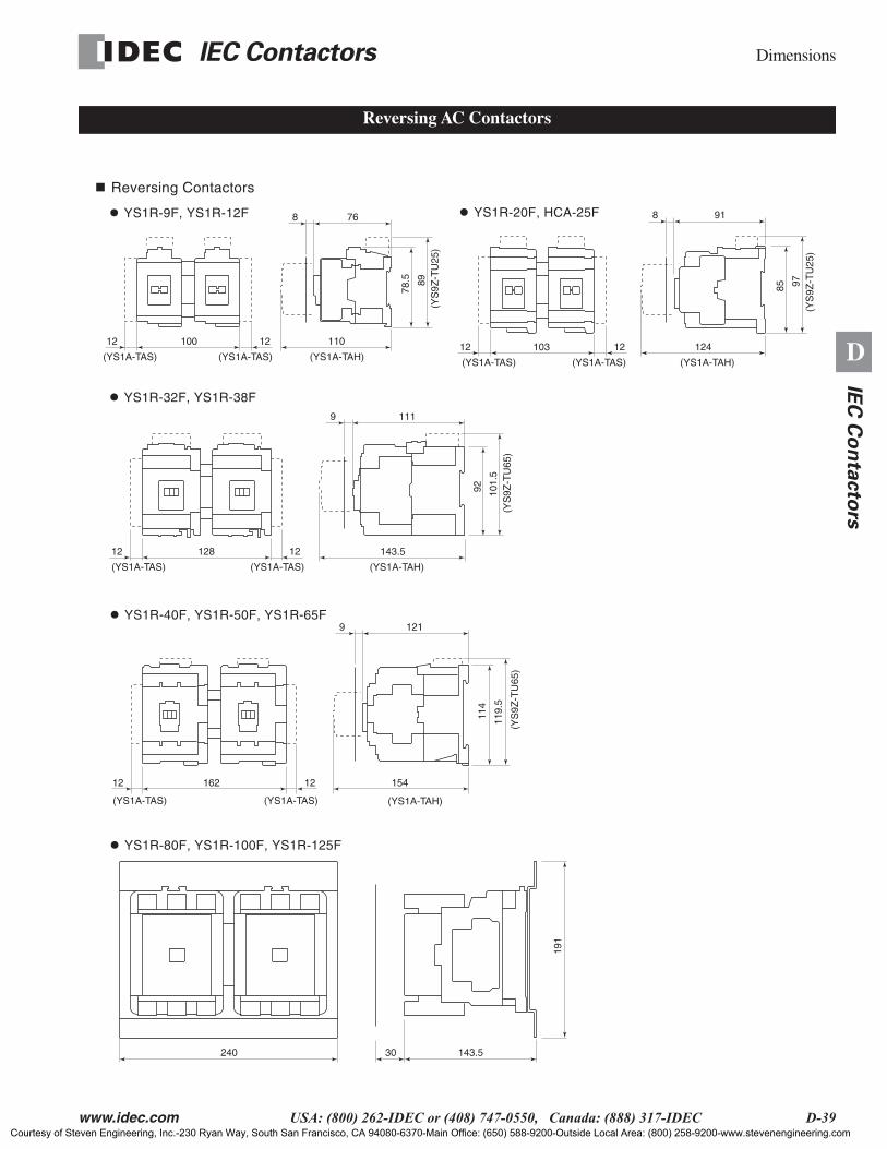
IEC Contactors
Dimensions
www.idec.com
USA: (800) 262-IDEC or (408) 747-0550, Canada: (888) 317-IDEC D-39
D
IEC
Co
nta
cto
rs
Reversing AC Contactors
Reversing Contactors
YS1R-9F, YS1R-12F
YS1R-40F, YS1R-50F, YS1R-65F
YS1R-80F, YS1R-100F, YS1R-125F
YS1R-20F, HCA-25F
YS1R-32F, YS1R-38F
10012 12
(YS1A-TAS) (YS1A-TAS)
110
78.5 89
(YS
9Z-T
U25
)
(YS1A-TAH)
768
10312 12
(YS1A-TAS) (YS1A-TAS)
124
240 30 143.5
191
85 97(Y
S9Z
-TU
25)
(YS1A-TAH)
918
12 12 154162
(YS1A-TAH)
114
119.
5
(YS
9Z-T
U65
)
1219
12812 12
(YS1A-TAS) (YS1A-TAS)
143.5
92 101.
5(Y
S9Z
-TU
65)
(YS1A-TAH)
1119
(YS1A-TAS) (YS1A-TAS)
Courtesy of Steven Engineering, Inc.-230 Ryan Way, South San Francisco, CA 94080-6370-Main Office: (650) 588-9200-Outside Local Area: (800) 258-9200-www.stevenengineering.com

Dimensions
IEC Contactors
D-40
www.idec.com
USA: (800) 262-IDEC or (408) 747-0550, Canada: (888) 317-IDEC
D
IE
C C
on
tacto
rs
Reversing Contactors
YS1R-150F YS1R-180F
YS1R-220F, YS1R-300F
200300
239
169.5
305 225
195
269
300 200
239
169.5
Courtesy of Steven Engineering, Inc.-230 Ryan Way, South San Francisco, CA 94080-6370-Main Office: (650) 588-9200-Outside Local Area: (800) 258-9200-www.stevenengineering.com

IEC Contactors
Dimensions
www.idec.com
USA: (800) 262-IDEC or (408) 747-0550, Canada: (888) 317-IDEC D-41
D
IEC
Co
nta
cto
rs
Reversing AC Starters
Reversing Starters
YS2R-9F, YS2R-12F
YS2R-40F, YS2R-50F, YS2R-65F YS2R-20F, YS2R-25F
YS2R-80F, YS2R-100F, YS2R-125F
YS2R-32F, YS2R-38F
128
76100.5
143.5240
250
133.
5
91103
168
162 121
150
111128
45 90.5
56 106
92.545
10556
100 127.5
Courtesy of Steven Engineering, Inc.-230 Ryan Way, South San Francisco, CA 94080-6370-Main Office: (650) 588-9200-Outside Local Area: (800) 258-9200-www.stevenengineering.com
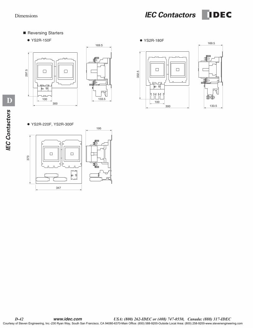
Dimensions
IEC Contactors
D-42
www.idec.com
USA: (800) 262-IDEC or (408) 747-0550, Canada: (888) 317-IDEC
D
IE
C C
on
tacto
rs
Reversing Starters
YS2R-150F
YS2R-220F, YS2R-300F
YS2R-180F
133.5300
169.5
347
195
373
300
133.5
297.
5
169.5
332.
5
100100
Courtesy of Steven Engineering, Inc.-230 Ryan Way, South San Francisco, CA 94080-6370-Main Office: (650) 588-9200-Outside Local Area: (800) 258-9200-www.stevenengineering.com

IEC Contactors
Mounting/Wiring
www.idec.com
USA: (800) 262-IDEC or (408) 747-0550, Canada: (888) 317-IDEC D-43
D
IEC
Co
nta
cto
rs
Mounting, Screw Mounting, and Rail Mounting
Non-Reversing AC Contactors
Non-Reversing Contactors
YS1N, YS1N-12F YS1N-40F, YS1N-50F, YS1N-65F
YS1N-80F, YS1N-100F, YS1N-125F
YS1N-150F
YS1N-20F, YS1N-25F
YS1N-32F, YS1N-38F
345
35
4.5
355.2 4.5
80
110
19
7655
95 100
6
504
70 7510
.5
4.5
867
125
130
25
48 50 5215
.52-4.8 DIA.MTG HOLES(M4)
2-4.8 DIA.MTG HOLES(M4)
DIN RAIL 35mm
2-4.8 DIA.MTG HOLES(M4)
2-4.8 DIA.MTG HOLES(M4) DIN RAIL 75mm
2-4.8 DIA.MTG HOLES(M4)
2-4.8 DIA.MTG HOLES(M4)
DIN RAIL 35mm
2-4.8 DIA.MTG HOLES(M4)
DIN RAIL 35mm
70 755
4-6 DIA.MTG HOLES(M5)
4-M6 MTG HOLES
A B
B A
10015
Courtesy of Steven Engineering, Inc.-230 Ryan Way, South San Francisco, CA 94080-6370-Main Office: (650) 588-9200-Outside Local Area: (800) 258-9200-www.stevenengineering.com
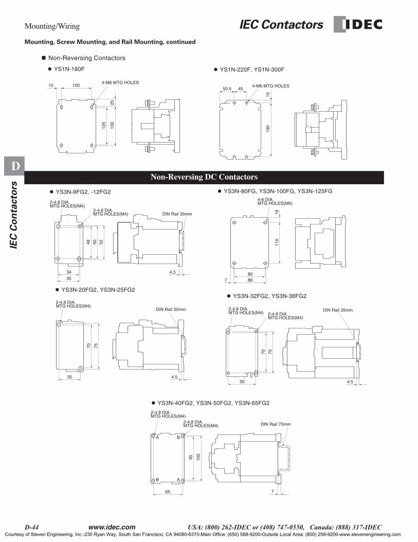
Mounting/Wiring
IEC Contactors
D-44
www.idec.com
USA: (800) 262-IDEC or (408) 747-0550, Canada: (888) 317-IDEC
D
IE
C C
on
tacto
rs
Mounting, Screw Mounting, and Rail Mounting, continued
Non-Reversing Contactors
YS1N-180F YS1N-220F, YS1N-300F
125
1001550.5 45
130
25
190
10
4-M6 MTG HOLES4-M6 MTG HOLES
Non-Reversing Contactors, DC Operated
YS3N-9FG2, -12FG2 YS3N-80FG, YS3N-100FG, YS3N-125FG
YS3N-20FG2, YS3N-25FG2 YS3N-32FG2, YS3N-38FG2
YS3N-40FG2, YS3N-50FG2, YS3N-65FG2
8011
019
867
4.5
4.54.5
4-6 DIA.MTG HOLES(M5)2-4.8 DIA.
MTG HOLES(M4)
2-4.8 DIA.MTG HOLES(M4)
2-4.8 DIA.MTG HOLES(M4)
2-4.8 DIA.MTG HOLES(M4)
2-4.8 DIA.MTG HOLES(M4)
2-4.8 DIA.MTG HOLES(M4)
DIN Rail 35mm
DIN Rail 35mm DIN Rail 35mm
DIN Rail 75mm
2-4.8 DIA.MTG HOLES(M4)
52504870 75
70
95 100
75
7
34
35
3550
65
A B
B A
Non-Reversing DC Contactors
Courtesy of Steven Engineering, Inc.-230 Ryan Way, South San Francisco, CA 94080-6370-Main Office: (650) 588-9200-Outside Local Area: (800) 258-9200-www.stevenengineering.com

IEC Contactors
Mounting/Wiring
www.idec.com
USA: (800) 262-IDEC or (408) 747-0550, Canada: (888) 317-IDEC D-45
D
IEC
Co
nta
cto
rs
Mounting, Screw Mounting, and Rail Mounting
Reversing AC Contactors
Reversing Contactors
YS1R-9F, YS1R-12F
YS1R-40F, YS1R-50F, YS1R-65F
YS1R-80F, YS1R-100F, YS1R-125F
YS1R-20F, YS1R-25F
YS1R-32F, YS1R-38F
34
35
4.5
35 4.5
765
95 100
50
70 75
4.5
48 50 5215
.5
345 22
35 21
4-4.8 DIA.MTG HOLES(M4)
4-4.8 DIA.MTG HOLES(M4)
DIN RAIL 35mm
4-4.8 DIA.MTG HOLES(M4)
4-7 DIA. MTG HOLES(M6)
DIN RAIL 75mm
4-4.8 DIA.MTG HOLES(M4)
DIN RAIL 35mm
4-4.8 DIA.MTG HOLES(M4)
DIN RAIL 35mm
355.2 22.5
70 755
504 20
4-4.8 DIA.MTG HOLES(M4)
10.5
B A
A B
655 22
4-4.8 DIA.MTG HOLES(M4)
B A
A B
6
220
175
10
8
10.57
10
Courtesy of Steven Engineering, Inc.-230 Ryan Way, South San Francisco, CA 94080-6370-Main Office: (650) 588-9200-Outside Local Area: (800) 258-9200-www.stevenengineering.com

Mounting/Wiring
IEC Contactors
D-46
www.idec.com
USA: (800) 262-IDEC or (408) 747-0550, Canada: (888) 317-IDEC
D
IE
C C
on
tacto
rs
Mounting, Screw Mounting, and Rail Mounting, continued
Reversing Contactors
YS1R-150F
YS1R-220F, YS1R-300F
YS1R-180F
270
221
8
15
275
15
251
8
270
221
8
15
15
4-M8 MTG HOLES4-M8 MTG HOLES
4-M8 MTG HOLES
10
20
10
20
10
30
15
15
Courtesy of Steven Engineering, Inc.-230 Ryan Way, South San Francisco, CA 94080-6370-Main Office: (650) 588-9200-Outside Local Area: (800) 258-9200-www.stevenengineering.com
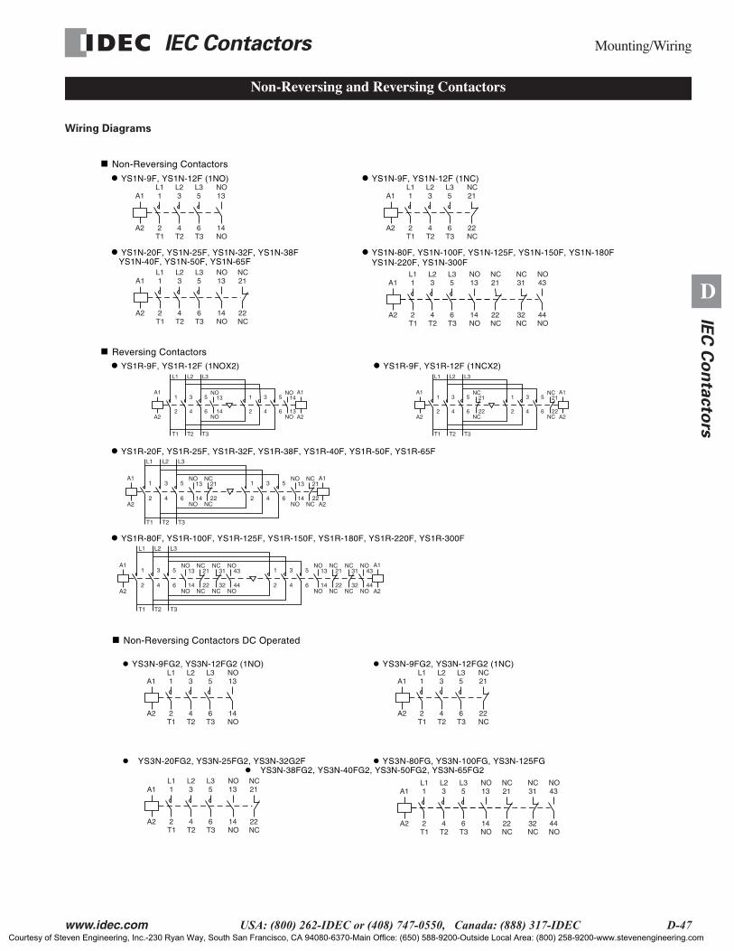
IEC Contactors
Mounting/Wiring
www.idec.com
USA: (800) 262-IDEC or (408) 747-0550, Canada: (888) 317-IDEC D-47
D
IEC
Co
nta
cto
rs
Wiring Diagrams
Non-Reversing and Reversing Contactors
n Non-Reversing Contactors
l YS1N-9F, YS1N-12F (1NO)
n Reversing Contactors
l YS1R-9F, YS1R-12F (1NOX2)
l YS1R-20F, YS1R-25F, YS1R-32F, YS1R-38F, YS1R-40F, YS1R-50F, YS1R-65F
l YS1N-9F, YS1N-12F (1NC)
YS1N-40F, YS1N-50F, YS1N-65Fl YS1N-80F, YS1N-100F, YS1N-125F, YS1N-150F, YS1N-180F
YS1N-220F, YS1N-300Fl YS1N-20F, YS1N-25F, YS1N-32F, YS1N-38F
1A1
2T1
L1
A2
3
4T2
L25
6T3
L313
14NO
NO
1A1
2T1
L1
A2
3
4T2
L25
6T3
L313
14NO
NO
1A1
2T1
L1
A2
3
4T2
L25
6T3
L321
22NC
NC
A1
2
T1
L1
A2
A1
A24
T2
L2
6
1 3 5
2 4 6
1 3 5
T3
L3
13
14
NO
NO
14
13
NO
NO
21
22NC
NC1A1
2T1
L1
A2
3
4T2
L25
6T3
L313
14NO
NO21
22NC
NC43
44NO
NO31
32NC
NC
l YS1R-9F, YS1R-12F (1NCX2)
A1
2
T1
L1
A2
A1
A24
T2
L2
6
1 3 5
2 4 6
1 3 5
T3
L3
21
22
NC
NC
21
22
NC
NC
A1
2
T1
L1
A2
A1
A24
T2
L2
6
1 3 5
2 4 6
1 3 5
T3
L3
21
22
13
14
NC
NC
NO
NO
13
14
NO
NO
21
22
NC
NC
l YS1R-80F, YS1R-100F, YS1R-125F, YS1R-150F, YS1R-180F, YS1R-220F, YS1R-300F
A1
2
T1
L1
A2
A1
A24
T2
L2
6
1 3 5
2 4 6
1 3 5
T3
L3
21
22
13
14
NC
NC
NO
NO
43
44
31
32
NO
NO
NC
NC
21
22
13
14
NC
NC
NO
NO
43
44
31
32
NO
NO
NC
NC
n Non-Reversing Contactors DC Operated
l YS3N-9FG2, YS3N-12FG2 (1NO) l YS3N-9FG2, YS3N-12FG2 (1NC)
l YS3N-38FG2, YS3N-40FG2, YS3N-50FG2, YS3N-65FG2l YS3N-80FG, YS3N-100FG, YS3N-125FGl YS3N-20FG2, YS3N-25FG2, YS3N-32G2F
1A1
2T1
L1
A2
3
4T2
L25
6T3
L313
14NO
NO
1A1
2T1
L1
A2
3
4T2
L25
6T3
L313
14NO
NO
1A1
2T1
L1
A2
3
4T2
L25
6T3
L321
22NC
NC
21
22NC
NC1A1
2T1
L1
A2
3
4T2
L25
6T3
L313
14NO
NO21
22NC
NC43
44NO
NO31
32NC
NC
Courtesy of Steven Engineering, Inc.-230 Ryan Way, South San Francisco, CA 94080-6370-Main Office: (650) 588-9200-Outside Local Area: (800) 258-9200-www.stevenengineering.com

Mounting/Wiring
IEC Contactors
D-48
www.idec.com
USA: (800) 262-IDEC or (408) 747-0550, Canada: (888) 317-IDEC
D
IE
C C
on
tacto
rs
Wiring Diagrams
Non-Reversing and Reversing Starters
Non-Reversing Starters YS2N-9FD, YS2N-12FD
(1NO) (1NC) (1NO) (1NC)
Thermal Overload Relays
YS2N-20FD, YS2N-25FD, YS2N-32FD, YS2N-38FD, YS2N-40FD, YS2N-50FD, YS2N-65FD
YS2N-80FD, YS2N-100FD, YS2N-125FD,
YS2N-220FD, YS2N-300FD
YS2N-150FD, YS2N-180FD
Reversing Starters YS2R-9FD, YS2R-12FD
YS2R-20FD, YS2R-25FD, YS2R-32FD, YS2R-38FD,YS2R-40FD, YS2R-50FD, YS2R-65FD
YS2R-80FD, YS2R-100FD, YS2R-125FD, YS2R-150FD,YS2R-180FD
YS2R-220FD, YS2R-300FD
1A1
2
T1
L1
A2
3
4
T2
L2 5
6
1 3 5
2 4 6 98 96
97 95
T3
L3 13
14
T1 T2
1 3 5
2 4 6 98 96
97 95
T3
1A1
2
T1
L1
A2
3
4
T2
L2 5
6
1 3 5
2 4 6 98 96
97 95
T3
L3 21
1
2
T1
L1 3
4
T2
L2 5
6
1 3 5
2 4 6 98 96
97 95
T3
L3
A1
2
L1
A2
A1
A24
L2
6
1 3 5
2 4 6
1 3 5
L3
13
14
14
13
T1 T2
1 3 5
2 4 6 98 96
97 95
T3
T1 T2
1 3 5
2 4 6 98 96
97 95
T3
T1 T2
1 3 5
2 4 6 98 96
97 95
T3
A1
2
L1
A2
A1
A24
L2
6
1 3 5
2 4 6
1 3 5
L3
21
22
21
2222
1
2
T1
L1 3
4
T2
L2 5
6
1 3 5
2 4 6 98 96
97 95
T3
L3
T1 T22 4 6 98 96
97 95
T3
L1 L21 3 5 L3
A1
A2
13
14
21
22
A1
A2
13
14
21
22
43
44
31
32
1
2
L1 3
4
L2 5
6
1 3 5
2 4 6 98 96
97 95
L3A1
A2
13
14
21
22
43
44
31
32
A1
2
L1
A2
A1
A24
L2
6
1 3 5
2 4 6
1 3 5
L3
21
22
13
14
NC
NC
NO
NO
13
14
NO
NO
21
22
NC
NC
A1
2
L1
A2
A1
A24
L2
6
1 3 5
2 4 6
1 3 5
L3
21
22
13
14
NC
NC
NO
NO
43
44
31
32
NO
NO
NC
NC
21
22
13
14
NC
NC
NO
NO
43
44
31
32
NO
NO
NC
NC
A1
2
L1
A2
A1
A24
L2
6
1 3 5
2 4 6
1 3 5
L3
21
22
13
14
NC
NC
NO
NO
43
44
31
32
NO
NO
NC
NC
21
22
13
14
NC
NC
NO
NO
43
44
31
32
NO
NO
NC
NC
YS1T-RHA F D
1 3 5
2 4 6 98 96
97 95
Courtesy of Steven Engineering, Inc.-230 Ryan Way, South San Francisco, CA 94080-6370-Main Office: (650) 588-9200-Outside Local Area: (800) 258-9200-www.stevenengineering.com
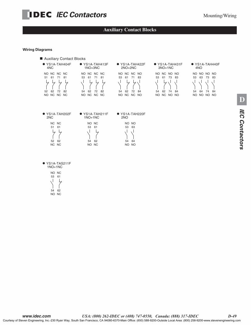
IEC Contactors
Mounting/Wiring
www.idec.com
USA: (800) 262-IDEC or (408) 747-0550, Canada: (888) 317-IDEC D-49
D
IEC
Co
nta
cto
rs
Wiring Diagrams
Auxiliary Contact Blocks
Auxiliary Contact Blocks
YS1A-TAH202F
51
52NC
NC
YS1A-TAH211F
61
62NC
NC
2NC 1NO+1NC 2NO
53
54NO
NO61
62NC
NC53
54NO
NO63
64NO
NO
YS1A-TAH220F
YS1A-TAH440F
53
54NO
NO
YS1A-TAH431F
63
64NO
NO73
74NO
NO
4NO4NC 3NO+1NC2NO+2NC1NO+3NC
83
84NO
NO53
54NO
NO61
62NC
NC73
74NO
NO83
84NO
NO53
54NO
NO61
62NC
NC71
72NC
NC83
84NO
NO53
54NO
NO61
62NC
NC71
72NC
NC81
82NC
NC51
52NO
NO61
62NC
NC71
72NC
NC81
82NC
NC
YS1A-TAH422F YS1A-TAH413F YS1A-TAH404F
1NO+1NC
53
54NO
NO61
62NC
NC
YS1A-TAS211F
Courtesy of Steven Engineering, Inc.-230 Ryan Way, South San Francisco, CA 94080-6370-Main Office: (650) 588-9200-Outside Local Area: (800) 258-9200-www.stevenengineering.com
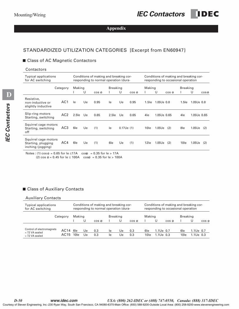
Mounting/Wiring
IEC Contactors
D-50
www.idec.com
USA: (800) 262-IDEC or (408) 747-0550, Canada: (888) 317-IDEC
D
IE
C C
on
tacto
rs
Appendix
STANDARDIZED UTILIZATION CATEGORIES [Excerpt from EN60947]
Class of AC Magnetic Contactors
Contactors
Typical applications for AC switching
Conditions of making and breaking cor-responding to normal operation (dura-
Conditions of making and breaking cor-responding to occasional operation
Conditions of making and breaking cor-responding to normal operation (dura-
Conditions of making and breaking cor-responding to occasional operation
Resistive, non-inductive orslightly inductive
Category MakingI
IeAC1
Breakingcos U I cos U I cos U I cos U
0.95Ue Ie 0.95Ue 1.5Ie 0.81.05Ue 1.5Ie 0.81.05Ue
Class of Auxiliary Contacts
Auxiliary Contacts
Typical applications for AC switching
Control of electromagnets< 72 VA sealed> 72 VA sealed
Category MakingI
6IeAC14
Breaking
Making Breaking
Making Breakingcos U I cos U I cos U I cos U
0.3Ue Ie 0.3Ue 6Ie 0.71.1Ue0.3
6Ie 0.71.1Ue10IeAC15 0.3Ue Ie 0.3Ue 10Ie 1.1Ue 10Ie 0.31.1Ue
Squirrel cage motorsStarting, switching off
6IeAC3 (1)Ue Ie (1)0.17Ue 10Ie 1.05Ue 8Ie 1.05Ue
Squirrel cage motorsStarting, plugginginching (jogging)
6IeAC4 (1)Ue 6Ie (1)
(2)
(2)Ue 12Ie 1.05Ue
(2)
(2)10Ie 1.05Ue
Slip-ring motorsStarting, switching
2.5IeAC2 0.65Ue 2.5Ie 0.65Ue 4Ie 0.651.05Ue 4Ie 0.651.05Ue
Notes : (1) cos = 0.65 for Ie ≤17A cos = 0.35 for Ie > 17A (2) cos = 0.45 for Ie ≤ 100A cos = 0.35 for Ie > 100A
Courtesy of Steven Engineering, Inc.-230 Ryan Way, South San Francisco, CA 94080-6370-Main Office: (650) 588-9200-Outside Local Area: (800) 258-9200-www.stevenengineering.com
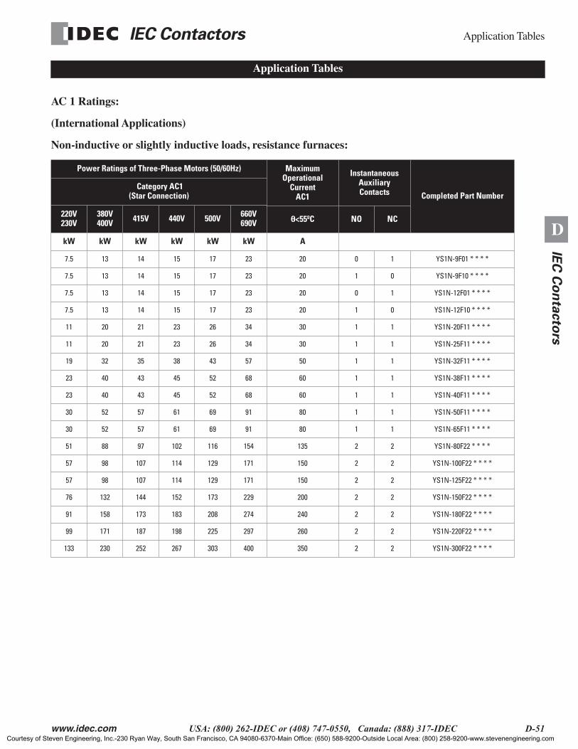
IEC Contactors
Application Tables
www.idec.com
USA: (800) 262-IDEC or (408) 747-0550, Canada: (888) 317-IDEC D-51
D
IEC
Co
nta
cto
rs
AC 1 Ratings:
(International Applications)
Non-inductive or slightly inductive loads, resistance furnaces:
Power Ratings of Three-Phase Motors (50/60Hz) MaximumOperational
Current AC1
Instantaneous Auxiliary Contacts Completed Part Number
Category AC1(Star Connection)
220V230V
380V400V 415V 440V 500V 660V
690V θθθθ
<55ºC NO NC
kW kW kW kW kW kW A
7.5 13 14 15 17 23 20 0 1 YS1N-9F01 * * * *
7.5 13 14 15 17 23 20 1 0 YS1N-9F10 * * * *
7.5 13 14 15 17 23 20 0 1 YS1N-12F01 * * * *
7.5 13 14 15 17 23 20 1 0 YS1N-12F10 * * * *
11 20 21 23 26 34 30 1 1 YS1N-20F11 * * * *
11 20 21 23 26 34 30 1 1 YS1N-25F11 * * * *
19 32 35 38 43 57 50 1 1 YS1N-32F11 * * * *
23 40 43 45 52 68 60 1 1 YS1N-38F11 * * * *
23 40 43 45 52 68 60 1 1 YS1N-40F11 * * * *
30 52 57 61 69 91 80 1 1 YS1N-50F11 * * * *
30 52 57 61 69 91 80 1 1 YS1N-65F11 * * * *
51 88 97 102 116 154 135 2 2 YS1N-80F22 * * * *
57 98 107 114 129 171 150 2 2 YS1N-100F22 * * * *
57 98 107 114 129 171 150 2 2 YS1N-125F22 * * * *
76 132 144 152 173 229 200 2 2 YS1N-150F22 * * * *
91 158 173 183 208 274 240 2 2 YS1N-180F22 * * * *
99 171 187 198 225 297 260 2 2 YS1N-220F22 * * * *
133 230 252 267 303 400 350 2 2 YS1N-300F22 * * * *
Application Tables
Courtesy of Steven Engineering, Inc.-230 Ryan Way, South San Francisco, CA 94080-6370-Main Office: (650) 588-9200-Outside Local Area: (800) 258-9200-www.stevenengineering.com
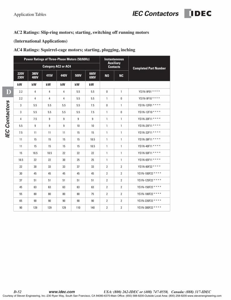
Application Tables
IEC Contactors
D-52
www.idec.com
USA: (800) 262-IDEC or (408) 747-0550, Canada: (888) 317-IDEC
D
IE
C C
on
tacto
rs
AC2 Ratings: Slip-ring motors; starting, switching off running motors
(International Applications)
AC4 Ratings: Squirrel-cage motors; starting, plugging, inching
Power Ratings of Three-Phase Motors (50/60Hz) Instantaneous Auxiliary Contacts Completed Part NumberCategory AC2 or AC4
220V230V
380V400V 415V 440V 500V 660V
690V NO NC
kW kW kW kW kW kW
2.2 4 4 4 5.5 5.5 0 1 YS1N-9F01 * * * *
2.2 4 4 4 5.5 5.5 1 0 YS1N-9F10 * * * *
3 5.5 5.5 5.5 5.5 7.5 0 1 YS1N-12F01 * * * *
3 5.5 5.5 5.5 5.5 7.5 1 0 YS1N-12F10 * * * *
4 7.5 9 9 9 9 1 1 YS1N-20F11 * * * *
5.5 9 9 9 10 10 1 1 YS1N-25F11 * * * *
7.5 11 11 11 15 15 1 1 YS1N-32F11 * * * *
11 15 15 15 15 18.5 1 1 YS1N-38F11 * * * *
11 15 15 15 15 18.5 1 1 YS1N-40F11 * * * *
15 18.5 18.5 22 22 22 1 1 YS1N-50F11 * * * *
18.5 22 22 30 25 25 1 1 YS1N-65F11 * * * *
22 30 33 33 37 33 2 2 YS1N-80F22 * * * *
30 45 45 45 45 45 2 2 YS1N-100F22 * * * *
37 51 51 51 51 51 2 2 YS1N-125F22 * * * *
45 63 63 63 63 63 2 2 YS1N-150F22 * * * *
55 80 80 80 80 75 2 2 YS1N-180F22 * * * *
65 90 90 90 90 90 2 2 YS1N-220F22 * * * *
90 129 129 129 110 140 2 2 YS1N-300F22 * * * *
Courtesy of Steven Engineering, Inc.-230 Ryan Way, South San Francisco, CA 94080-6370-Main Office: (650) 588-9200-Outside Local Area: (800) 258-9200-www.stevenengineering.com
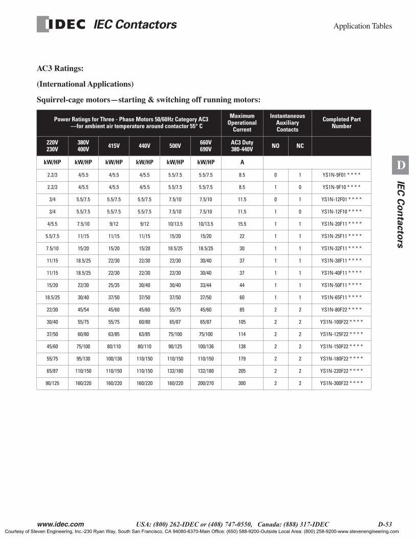
IEC Contactors
Application Tables
www.idec.com
USA: (800) 262-IDEC or (408) 747-0550, Canada: (888) 317-IDEC D-53
D
IEC
Co
nta
cto
rs
AC3 Ratings:
(International Applications)
Squirrel-cage motors—starting & switching off running motors:
Power Ratings for Three - Phase Motors 50/60Hz Category AC3 —for ambient air temperature around contactor 55° C
Maximum Operational
Current
Instantaneous AuxiliaryContacts
Completed Part Number
220V230V
380V400V 415V 440V 500V 660V
690VAC3 Duty380-440V NO NC
kW/HP kW/HP kW/HP kW/HP kW/HP kW/HP A
2.2/3 4/5.5 4/5.5 4/5.5 5.5/7.5 5.5/7.5 8.5 0 1 YS1N-9F01 * * * *
2.2/3 4/5.5 4/5.5 4/5.5 5.5/7.5 5.5/7.5 8.5 1 0 YS1N-9F10 * * * *
3/4 5.5/7.5 5.5/7.5 5.5/7.5 7.5/10 7.5/10 11.5 0 1 YS1N-12F01 * * * *
3/4 5.5/7.5 5.5/7.5 5.5/7.5 7.5/10 7.5/10 11.5 1 0 YS1N-12F10 * * * *
4/5.5 7.5/10 9/12 9/12 10/13.5 10/13.5 15.5 1 1 YS1N-20F11 * * * *
5.5/7.5 11/15 11/15 11/15 15/20 15/20 22 1 1 YS1N-25F11 * * * *
7.5/10 15/20 15/20 15/20 18.5/25 18.5/25 30 1 1 YS1N-32F11 * * * *
11/15 18.5/25 22/30 22/30 22/30 30/40 37 1 1 YS1N-38F11 * * * *
11/15 18.5/25 22/30 22/30 22/30 30/40 37 1 1 YS1N-40F11 * * * *
15/20 22/30 25/35 30/40 30/40 33/44 44 1 1 YS1N-50F11 * * * *
18.5/25 30/40 37/50 37/50 37/50 37/50 60 1 1 YS1N-65F11 * * * *
22/30 45/54 45/60 45/60 55/75 45/60 85 2 2 YS1N-80F22 * * * *
30/40 55/75 55/75 60/80 65/87 65/87 105 2 2 YS1N-100F22 * * * *
37/50 60/80 63/85 63/85 75/100 75/100 114 2 2 YS1N-125F22 * * * *
45/60 75/100 80/110 80/110 90/125 100/136 138 2 2 YS1N-150F22 * * * *
55/75 95/130 100/136 110/150 110/150 110/150 179 2 2 YS1N-180F22 * * * *
65/87 110/150 110/150 110/150 132/180 132/180 205 2 2 YS1N-220F22 * * * *
90/125 160/220 160/220 160/220 160/220 200/270 300 2 2 YS1N-300F22 * * * *
Courtesy of Steven Engineering, Inc.-230 Ryan Way, South San Francisco, CA 94080-6370-Main Office: (650) 588-9200-Outside Local Area: (800) 258-9200-www.stevenengineering.com

Application Tables
IEC Contactors
D-54
www.idec.com
USA: (800) 262-IDEC or (408) 747-0550, Canada: (888) 317-IDEC
D
IE
C C
on
tacto
rs
DC Loads:
DC1, DC14 L/R=1msResistance Load (A)
DC2, DC4 L/R=15msDC Motor Load (A)
DC11 L/R=100msInductive Load (A)
No. of Series Connection Part No.
48V 110V 220V 48V 110V 220V 48V 110V 220V
12 10 1 3 1.5 0.25 1 0.7 0.8 1YS1N-9F##****12 10 6 6 4 1.2 5 3 0.6 2
12 12 12 40 8 4 8 4 1.5 313 10 1 3 1.5 0.25 1 0.7 0.2 1
YS1N-12F##****13 10 6 6 4 1.2 5 3 0.6 213 13 13 13 8 4 8 4 1.5 313 10 1 3 2 0.25 1 0.7 0.25 1
YS1N-20F11****13 10 6 6 4 1.2 5 3 0.6 213 13 13 13 8 4 8 4 1.5 315 12 1.5 8 2 0.4 3 1.2 0.3 1
YS1N-25F11****20 15 10 15 8 2 12 5 1.2 220 20 15 20 15 8 15 10 2 326 15 2 10 3 0.4 3 1.2 0.4 1
YS1N-32F11****26 26 15 20 10 3 20 5 1.5 226 26 26 25 20 10 20 15 2 330 15 2 10 3 0.4 5 1.5 0.4 1
YS1N-38F11****30 30 20 30 15 3 20 5 1.5 235 35 30 35 20 10 25 15 2 330 15 2 10 3 0.4 5 1.5 0.4 1
YS1N-40F11****30 30 20 30 15 3 20 5 1.5 235 35 30 35 20 10 25 15 2 330 15 2 15 3 0.4 5 1.5 0.4 1
YS1N-50F11****50 35 20 35 15 3 20 5 1.5 250 50 35 40 20 10 25 15 2 350 30 2 20 4 0.4 5 1.5 0.4 1
YS1N-65F11****65 50 20 40 25 3 20 5 1.5 265 65 50 50 30 20 25 15 2 365 35 3 30 4 0.5 — — — 1
YS1N-80F11****80 65 30 65 40 4 — — — 280 80 65 65 65 30 — — — 380 35 3 30 4 0.5 — — — 1
YS1N-100F11****93 80 40 80 50 4 — — — 293 93 80 80 65 40 — — — 380 35 3 30 4 0.5 — — — 1
YS1N-125F11****100 100 50 85 50 4 — — — 2125 125 100 100 65 50 — — — 3125 35 4 50 5 0.5 — — — 1
YS1N-150F11****125 100 65 125 80 5 — — — 2150 150 125 150 100 65 — — — 3125 35 4 50 5 0.5 — — — 1
YS1N-180F11****150 125 80 125 80 5 — — — 2180 180 150 180 100 80 — — — 3
LOA
DL1
T1
2 Series Connection
T3
L3
+V DC
-V DC
LOA
DL1
T1
3 Series Connection
L2
T2
T3
L3
-V DC+V DC
LOA
DL1
T1
1 Series Connection+V DC -V DC
Courtesy of Steven Engineering, Inc.-230 Ryan Way, South San Francisco, CA 94080-6370-Main Office: (650) 588-9200-Outside Local Area: (800) 258-9200-www.stevenengineering.com

IEC Contactors
Application Tables
www.idec.com
USA: (800) 262-IDEC or (408) 747-0550, Canada: (888) 317-IDEC D-55
D
IEC
Co
nta
cto
rs
Application to Star (Wye)-Delta Motor Starters
1. Regarding Star operation time is as follows: In case of small inertia (e.g. Non-load, MG set, fan, compressor) is less than 30 seconds. The limit for number of continuity starting is 3 times, more than need off time.
2. The term of electrical endurance is more than 0.5 million operations.
3-Phase Motor Power RatingType of Magnetic Contactors Type of Overload Relay
Voltage (V)Frequency (Hz)
Capacity Current
(kW) (HP) (A) Main Star Delta Part Number
200-240V
50/60 Hz
3.7 5 17.5 YS-9F YS-9F YS-9F RHA-25F/15DP
5.5 7.5 26 YS-9F YS-9F YS-9F RHA-25F/21DP
7.5 10 34 YS-9F YS-9F YS-20F RHA-65F/25D + TIB-65F
11 15 48 YS-20F YS-9F YS-25F RHA-65F/43D + TIB-65F
15 20 65 YS-32F YS-20F YS-32F RHA-65F/56D + TIB-65F
18.5 25 79 YS-32F YS-20F YS-38F RHA-125F/68DP
22 30 93 YS-32F YS-32F YS-50F RHA-125F/80DP
30 40 125 YS-50F YS-32F YS-65F RHA-125F/105DP
37 50 148 YS-50F YS-32F YS-80F RHA-150F/135DP
45 60 180 YS-80F YS-50F YS-100F RHA-180F/155DP
55 75 220 YS-125F YS-50 YS-100F RHA-300F/180D (with CT)
75 100 300 YS-180F YS-80F YS-150F RHA-400F/240D (with CT)
90 125 360 YS-220F YS-80F YS-180F RHA-500F/300D (with CT)
110 150 440 YS-300F YS-80F YS-220F RHA-500F/300D (with CT)
132 175 528 YS-300F YS-80F YS-300F RHA-750F/450D (with CT)
160 215 640 YS-400F YS-150F YS-300F RHA-750F/450D (with CT)
380-440V
50/60 Hz
3.7 5 8.7 YS-9F YS-9F YS-9F RHA-25F/8.5DP
5.5 7.5 13 YS-9F YS-9F YS-9F RHA-25F/11DP
7.5 10 17 YS-9F YS-9F YS-9F RHA-25F/15DP
11 15 24 YS-9F YS-9F YS-12F RHA-25F/21DP
15 20 32.5 YS-20F YS-9F YS-20F RHA-65F/32D + TIB-65F
18.5 25 39.5 YS-20F YS-9F YS-25F RHA-65F/35D + TIB-65F
22 30 46.5 YS-20F YS-20F YS-25F RHA-65F/43D + TIB-65F
30 40 62.5 YS-32F YS-20F YS-38F RHA-65F/56D + TIB-65F
37 50 74 YS-32F YS-20F YS-38F RHA-125F/68DP
45 60 90 YS-32F YS-32F YS-50F RHA-125F/80DP
55 75 110 YS-50F YS-32F YS-50F RHA-125F/105DP
75 100 150 YS-80F YS-32F YS-80F RHA-150F/135DP
90 125 180 YS-80F YS-50F YS-100F RHA-180F/155DP
110 150 220 YS-80F YS-50F YS-125F RHA-300F/180D (with CT)
132 175 264 YS-80F YS-50F YS-150F RHA-400F/240D (with CT)
160 215 320 YS-150F YS-80F YS-180F RHA-400F/240D (with CT)
200 267 400 YS-150F YS-80F YS-220F RHA-500F/300D (with CT)
250 333 500 YS-220F YS-80F YS-300F RHA-500F/450D (with CT)
300 — 600 YS-220F YS-150F YS-400F RHA-500F/450D (with CT)
Courtesy of Steven Engineering, Inc.-230 Ryan Way, South San Francisco, CA 94080-6370-Main Office: (650) 588-9200-Outside Local Area: (800) 258-9200-www.stevenengineering.com
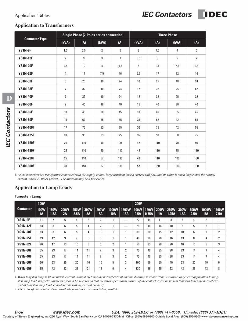
Application Tables
IEC Contactors
D-56 www.idec.com USA: (800) 262-IDEC or (408) 747-0550, Canada: (888) 317-IDEC
D
IEC
Co
nta
cto
rs
Application to Transformers
1. At the moment when transformer connected with the supply source, large transient inrush current will flow, and its value is much larger than the normal current (about 20 times greater). The duration may be a few cycles.
Application to Lamp Loads
Tungsten Lamp
1. When tungsten lamp is lit, its inrush current is about 30 times the normal current and the duration is about 10 milliseconds. In general application to tung-sten lamp load, magnetic contactors should be selected so that the rated operational current of the contactor will be no less than two times the normal cur-rent of tungsten lamp load, considered its making current capacity.
2. The value of above table shows available quantities as connected in parallel.
Contactor TypeSingle Phase (2-Poles series connection) Three Phase
(kVA) (A) (kVA) (A) (kVA) (A) (kVA) (A)
YS1N-9F 1.5 7.5 2 5 3 7.5 4 5
YS1N-12F 2 9 3 7 3.5 9 5 7
YS1N-20F 2.5 10 4 9.5 5 13 7.5 9.5
YS1N-25F 4 17 7.5 16 6.5 17 12 16
YS1N-32F 5 25 10 24 10 25 18 24
YS1N-38F 7 32 10 24 12 32 25 62
YS1N-40F 7 32 10 24 12 32 25 32
YS1N-50F 9 40 18 40 15 40 30 40
YS1N-65F 10 46 20 45 18 46 35 45
YS1N-80F 15 62 35 55 35 62 42 55
YS1N-100F 17 75 33 75 30 75 42 55
YS1N-125F 20 90 33 75 35 90 60 75
YS1N-150F 25 110 40 90 42 110 70 90
YS1N-180F 25 110 50 110 42 110 85 110
YS1N-220F 25 110 57 130 42 110 100 130
YS1N-300F 33 150 57 130 57 150 100 130
Contactor100V 200V
100W1A
150W1.5A
200W2A
250W2.5A
300W3A
500W5A
1000W10A
1500W15A
100W0.5A
150W0.75A
200W1A
250W1.25A
300W1.5A
500W2.5A
1000W5A
1500W7.5A
YS1N-9F 11 7 5 4 3 2 1 — 22 14 11 8 6 4 2 1
YS1N-12F 13 8 6 5 4 2 1 — 28 18 14 10 8 5 2 1
YS1N-20F 13 8 6 5 4 3 1 1 30 20 15 12 10 6 2 2
YS1N-25F 19 12 9 7 6 3 1 1 40 26 20 16 13 8 4 2
YS1N-32F 26 17 13 10 8 5 2 1 50 33 26 20 16 10 5 3
YS1N-38F 35 23 17 14 11 7 3 2 70 46 35 28 23 14 7 4
YS1N-40F 35 23 17 14 11 7 3 2 70 46 35 28 23 14 7 4
YS1N-50F 50 33 25 20 16 10 5 3 100 66 50 40 33 20 10 6
YS1N-65F 65 42 32 26 21 13 6 4 130 86 65 52 43 26 13 8
Courtesy of Steven Engineering, Inc.-230 Ryan Way, South San Francisco, CA 94080-6370-Main Office: (650) 588-9200-Outside Local Area: (800) 258-9200-www.stevenengineering.com

IEC Contactors Application Tables
www.idec.com USA: (800) 262-IDEC or (408) 747-0550, Canada: (888) 317-IDEC D-57
D
IEC
Co
nta
cto
rs
Fluorescent Lamp (rapid start time)
1. When fluorescent lamp lights, generally the starting current is a few times the normal current and its duration may be within a few seconds. Magnetic con-tactors should be selected so the rated operation current will be the same as the total load current of the fluorescent lamp loads.
2. The values of above table show available quantities as connected in parallel.3. ( ) values in above table show in the case of the light for Low power factor type.
Mercury Lamp
1. When mercury lamp lights, the starting current is about 1.5–1.8 times the normal current and its duration may be a few minutes (within 8 times). Magnetic contactors should be selected so the rated operational current will be the same as the total load current of the mercury lamp loads.
2. The values of above table show available quantities as connected in parallel.
Contactor
100V 200V
40W 60W 80W 100W 220W 40W 60W 80W 100W 220W
10.59A(1.2A)
20.96A(1.1A)
10.92A
11.17A
11.55A
22.5A
12.7A
10.29A(0.6A)
20.48A
(0.55A)
10.46A
10.58A
10.78A
21.3A
11.35A
22.5A
YS1N-9F 18(9)
11(10) 11 9 5 4 4 37
(18)22
(20) 23 18 14 8 8 4
YS1N-12F 23(11)
14(12) 15 11 9 5 5 48
(23)29
(25) 30 24 17 10 10 5
YS1N-20F 25(12)
15(13) 16 12 9 6 5 51
(25)31
(27) 32 25 19 11 11 6
YS1N-25F 33(16)
20(18) 21 17 12 8 7 68
(33)41
(36) 43 34 25 15 14 8
YS1N-32F 42(20)
26(22) 27 21 16 1 9 86
(41)52
(45) 54 43 32 20 18 10
YS1N-38F 59(29)
36(31) 38 29 22 14 12 120
(58)72
(63) 76 60 44 26 25 14
YS1N-40F 59(29)
36(31) 38 29 22 14 12 120
(58)72
(63) 76 60 44 26 25 14
YS1N-50F 84(41)
52(45) 54 42 32 20 18 172
(83)104(90) 108 86 64 38 37 20
YS1N-65F 100(54)
67(59) 70 55 41 26 24 224
(108)135
(118) 141 112 83 50 48 26
Contactor
100V (low power factor type/high power factor type) 200V (low power factor type/high power factor type)
40W 100W 200W 250W 300W 400W 700W 1000W 40W 100W 200W 250W 300W 400W 700W 1000W
1.25A/0.55A
2.6A/1.4A
4.6A/2.6A
5.1A/3.0A
6.0A/3.7A
8.0A/4.9A
14.5A/8.5A
21A/12A
0.53A/—
1.0A/0.65A
1.9A/1.2A
2.1A/1.5A
2.5A/1.8A
3.3A/2.3A
5.9A/4.1A
8.3A/5.8A
YS1N-9F 8/20 4/7 2/4 2/3 1/2 1/2 –/1 –/– 20/– 11/16 5/9 5/7 4/6 3/4 1/2 1/1
YS1N-12F 11/25 5/10 3/5 2/4 2/3 1/2 –/1 –/1 26/– 14/21 7/11 6/9 5/7 4/6 2/3 1/2
YS1N-20F 12/27 5/10 3/5 2/3 2/4 1/3 1/1 –/1 28/– 15/23 7/12 7/10 6/8 4/6 2/3 1/2
YS1N-25F 16/36 7/14 4/7 3/6 3/5 2/4 1/2 –/1 37/– 20/30 10/16 9/13 8/11 6/8 3/4 2/3
YS1N-32F 20/45 9/17 5/9 4/8 4/6 3/5 1/2 1/2 47/– 25/38 13/20 11/16 10/13 7/10 4/6 3/4
YS1N-38F 28/63 13/25 7/13 6/11 5/9 4/7 2/4 1/2 66/– 35/53 18/29 16/23 14/19 10/15 5/8 4/6
YS1N-40F 28/63 13/25 7/13 6/11 5/9 4/7 2/4 1/2 66/– 35/53 18/29 16/23 14/19 10/15 5/8 4/6
YS1N-50F 40/90 19/35 10/19 9/16 8/13 6/10 3/5 2/4 94/– 50/76 26/41 23/33 20/27 15/21 8/12 6/8
YS1N-65F 52/118 25/46 14/25 12/21 10/17 8/13 4/7 3/5 122/– 65/100 34/54 30/43 26/36 19/28 11/15 7/11
Courtesy of Steven Engineering, Inc.-230 Ryan Way, South San Francisco, CA 94080-6370-Main Office: (650) 588-9200-Outside Local Area: (800) 258-9200-www.stevenengineering.com
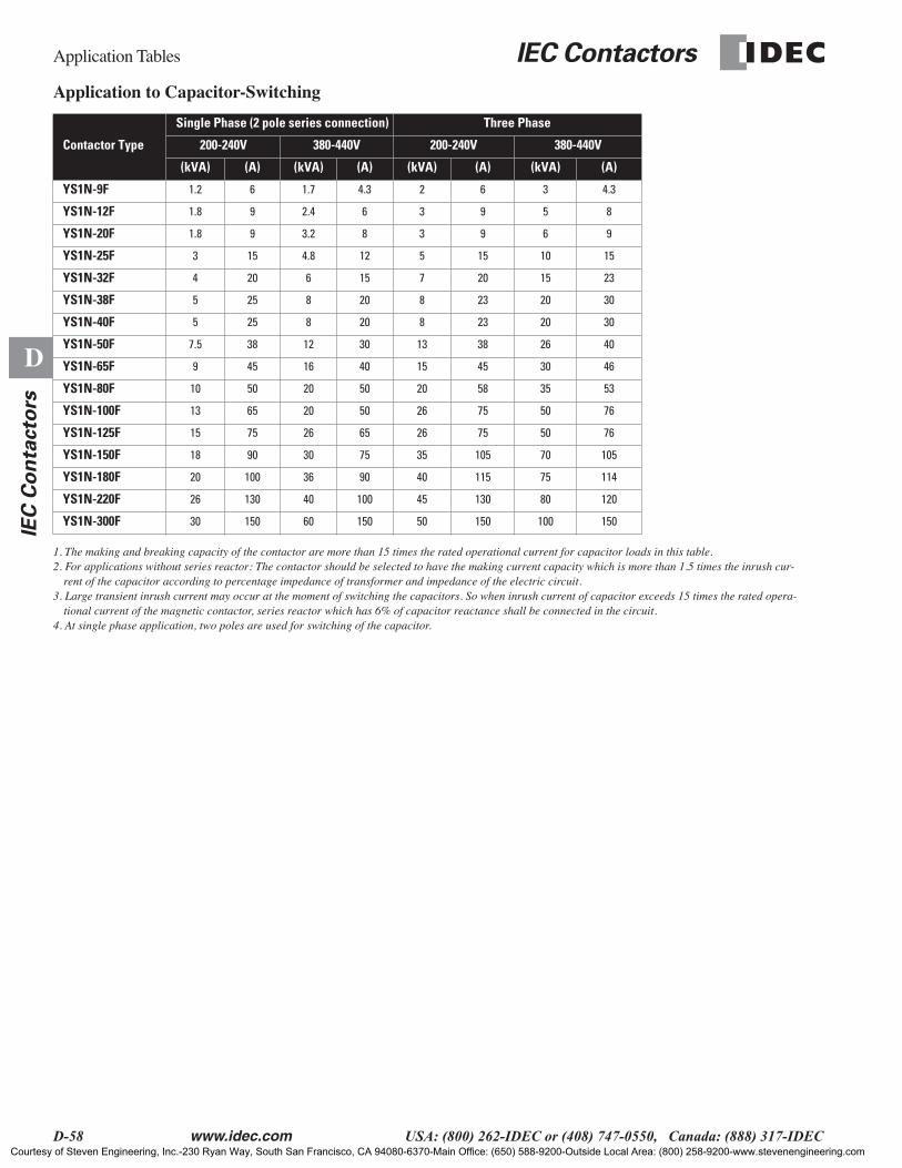
Application Tables IEC Contactors
D-58 www.idec.com USA: (800) 262-IDEC or (408) 747-0550, Canada: (888) 317-IDEC
D
IEC
Co
nta
cto
rs
Application to Capacitor-Switching
1. The making and breaking capacity of the contactor are more than 15 times the rated operational current for capacitor loads in this table.2. For applications without series reactor: The contactor should be selected to have the making current capacity which is more than 1.5 times the inrush cur-
rent of the capacitor according to percentage impedance of transformer and impedance of the electric circuit.3. Large transient inrush current may occur at the moment of switching the capacitors. So when inrush current of capacitor exceeds 15 times the rated opera-
tional current of the magnetic contactor, series reactor which has 6% of capacitor reactance shall be connected in the circuit.4. At single phase application, two poles are used for switching of the capacitor.
Contactor Type
Single Phase (2 pole series connection) Three Phase
200-240V 380-440V 200-240V 380-440V
(kVA) (A) (kVA) (A) (kVA) (A) (kVA) (A)
YS1N-9F 1.2 6 1.7 4.3 2 6 3 4.3
YS1N-12F 1.8 9 2.4 6 3 9 5 8
YS1N-20F 1.8 9 3.2 8 3 9 6 9
YS1N-25F 3 15 4.8 12 5 15 10 15
YS1N-32F 4 20 6 15 7 20 15 23
YS1N-38F 5 25 8 20 8 23 20 30
YS1N-40F 5 25 8 20 8 23 20 30
YS1N-50F 7.5 38 12 30 13 38 26 40
YS1N-65F 9 45 16 40 15 45 30 46
YS1N-80F 10 50 20 50 20 58 35 53
YS1N-100F 13 65 20 50 26 75 50 76
YS1N-125F 15 75 26 65 26 75 50 76
YS1N-150F 18 90 30 75 35 105 70 105
YS1N-180F 20 100 36 90 40 115 75 114
YS1N-220F 26 130 40 100 45 130 80 120
YS1N-300F 30 150 60 150 50 150 100 150
Courtesy of Steven Engineering, Inc.-230 Ryan Way, South San Francisco, CA 94080-6370-Main Office: (650) 588-9200-Outside Local Area: (800) 258-9200-www.stevenengineering.com
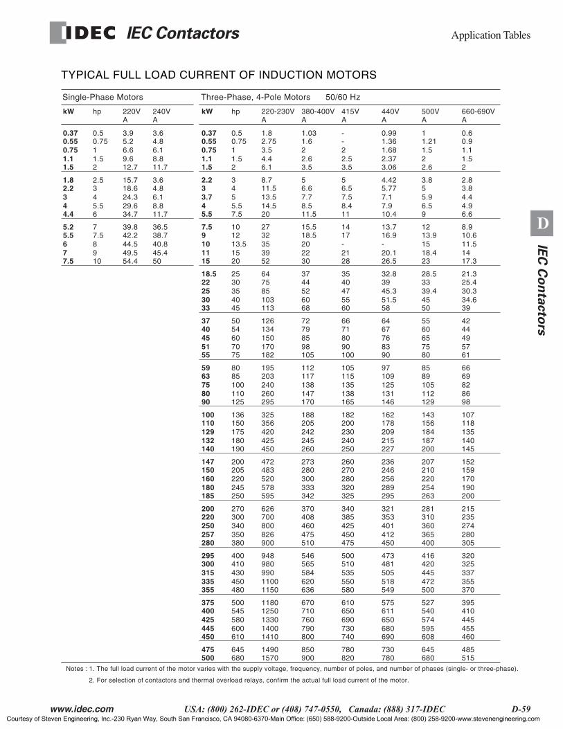
IEC Contactors Application Tables
www.idec.com USA: (800) 262-IDEC or (408) 747-0550, Canada: (888) 317-IDEC D-59
D
IEC
Co
nta
cto
rs
TYPICAL FULL LOAD CURRENT OF INDUCTION MOTORS
Single-Phase Motors
kW hp 220V 240VA
9.612.7
6.65.23.9
1.52
10.750.5
1.11.5
0.750.550.37
8.811.7
6.14.83.6
29.634.7
24.318.615.7
5.56
432.5
44.4
32.21.8
8.811.7
6.14.83.6
49.554.4
44.542.239.8
910
87.57
77.5
65.55.2
45.450
40.838.736.5
A
Three-Phase, 4-Pole Motors 50/60 Hz
kW hp 220-230V 380-400VA
4.46.1
3.52.751.8
1.52
10.750.5
1.11.5
0.750.550.37
2.63.5
21.61.03
A415V
2.53.5
2--
A440V
2.373.06
1.681.360.99
A500V
22.6
1.51.211
A660-690V
1.52
1.10.90.6
14.520
13.511.58.7
5.57.5
543
45.5
3.732.2
8.511.5
7.76.65
8.411
7.56.55
7.910.4
7.15.774.42
6.59
5.953.8
4.96.6
4.43.82.8
3952
353227
1520
13.51210
1115
1097.5
2230
2018.515.5
2128
-1714
20.126.5
-16.913.7
18.423
1513.912
1417.3
11.510.68.9
103113
857564
4045
353025
3033
252218.5
6068
524437
5560
474035
51.558
45.33932.8
4550
39.43328.5
34.639
30.325.421.3
170182
150134126
7075
605450
5155
454037
98105
857972
90100
807166
8390
766764
7580
656055
5761
494442
260295
240203195
110125
1008580
8090
756359
147170
138117112
138165
135115105
131146
12510997
112129
1058985
8698
826966
425450
420356325
180190
175150136
132140
129110100
245260
242205188
240250
230200182
215227
209178162
187200
184156143
140145
135118107
578595
520483472
245250
220205200
180185
160150147
333342
300280273
320325
280270260
289295
256246236
254263
220210207
190200
170159152
826900
800700626
350380
340300270
257280
250220200
475510
460408370
450475
425385340
412450
401353321
365400
360310281
280305
274235215
11001150
990980948
450480
430410400
335355
315300295
620636
584565546
550580
535510500
518549
505481473
472500
445420416
355370
337325320
14001410
133012501180
600610
580545500
445450
425400375
790800
760710670
730740
690650610
680690
650611575
595608
574540527
455460
445410395
15701490
680645
500475
900850
820780
780730
680645
515485
A
Notes : 1. The full load current of the motor varies with the supply voltage, frequency, number of poles, and number of phases (single- or three-phase).
2. For selection of contactors and thermal overload relays, confirm the actual full load current of the motor.
Courtesy of Steven Engineering, Inc.-230 Ryan Way, South San Francisco, CA 94080-6370-Main Office: (650) 588-9200-Outside Local Area: (800) 258-9200-www.stevenengineering.com
Application Tables IEC Contactors
D-60 www.idec.com USA: (800) 262-IDEC or (408) 747-0550, Canada: (888) 317-IDEC
D
IEC
Co
nta
cto
rs
Courtesy of Steven Engineering, Inc.-230 Ryan Way, South San Francisco, CA 94080-6370-Main Office: (650) 588-9200-Outside Local Area: (800) 258-9200-www.stevenengineering.com