Embed Size (px)
Citation preview
Moeller Wiring Manual 02/08
Contactors and relays
5
Page
Contactor relays 5-2
SmartWire 5-8
Contactors DIL, overload relays Z 5-24
Contactors DIL 5-30
Overload relays Z 5-35
ZEV electronic motor-protective system 5-38
Thermistor machine protection device EMT6 5-45
CMD contactor monitoring device 5-48
5-1
Moeller Wiring Manual 02/08
5
Contactors and relaysContactor relays
Contactor relays
Contactor relays are often used in control and regulating functions. They are used in large numbers for the indirect control of motors, valves, clutches and heating equipment.
In addition to the simplicity which they offer in project engineering, panel building, commissioning and maintenance, the high level of safety which they afford is a major factor in their favour.
SafetyThe contactor relay contacts themselves constitute a considerable safety feature. By design and construction they ensure electrical isolation between the actuating circuit and the operating circuit, in the de-energized state,
between the contact input and output. All Moeller contactor relays have double-break contacts.
The German Trade Associations demand that, for control systems of power-driven metalwork presses, the contacts of contactors must be interlocked and opposing. Interlocking means that the contacts are mechanically connected to one another such that N/C contacts and N/O contacts can never be closed simultaneously. At the same time, it is necessary to ensure that the contact gaps are at least 0.5 mm over the entire life, even when defective (e.g. when a contact is welded). The contactor relays DILER and DILA fulfil this requirement.
Moeller contactor relays
Moeller offers two ranges of contactor relays as a modular system:
• Contactor relays DILER,• Contactor relays DILA.
and the modules are described on the following pages.
Modular system
The modular system has many advantages for the user. The system is formed around basic units, which are equipped with additional functions by means of modules. Basic units are intrinsically functional units, consisting of an AC or DC drive and four auxiliary contacts.
Modules with auxiliary functions
Auxiliary contact modules have 2 or 4 contacts. The combination of normally open contacts and normally closed contacts comply with EN 50011. The auxiliary contact modules of the contactors DILEM and DILM cannot be snapped onto the basic device to prevent duplication of terminal markings e.g. contact 21/22 on the basic unit and 21/22 on the add-on auxiliary contact module.
The DILA and DILM7 to DILM32 contactors of the DILA-XHIR11 auxilary contact are available specially for switching very low signals for electronic applications.
5-2
Contactors and relaysContactor relays
Moeller Wiring Manual 02/08
5
The system and the Standard
European Standard EN 50011 “Terminal markings, reference numbers and reference letters for certain contactor relays” has a direct bearing on the use and application of the modular system. There are various types, which the Standard differentiates between by means of reference numbers and reference letters, depending on the number and position of the make and N/C contacts in the device, and their terminal markings.
Ideally devices with the reference letter E should be used. The basic devices DILA-40, DILA-31, DILA-22 as well as DILER-40, DILER-31 and DILER-22 comply with the E version.
For 6 and 8 pole contactor relays, the “E” version means that four make contacts must be arranged in the lower/rear contact level. If, for example, the available auxiliary contact modules are used in the DILA-22 and DILA-31, they result in contact combinations with reference letters X and Y.
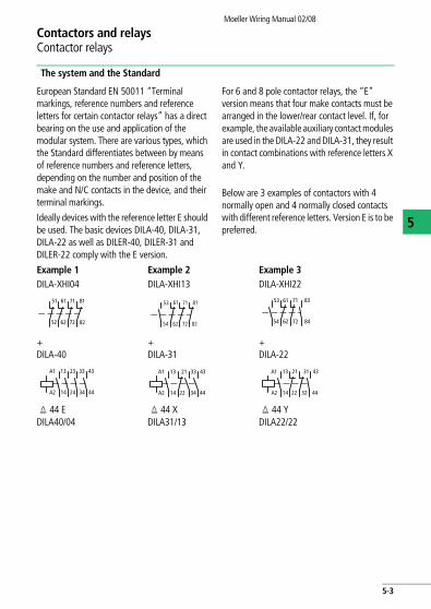
Below are 3 examples of contactors with 4 normally open and 4 normally closed contacts with different reference letters. Version E is to be preferred.
Example 1 Example 2 Example 3DILA-XHI04 DILA-XHI13 DILA-XHI22
+DILA-40
+DILA-31
+DILA-22
q 44 EDILA40/04
q 44 XDILA31/13
q 44 YDILA22/22
51
52
61
62
71
72 82
81 53 61 71 81
82726254 54
53 61
62
71
72
83
84
14
13 33
34
43
44
A1
A2
23
24 14
13 21
22
33
34
43
44
A1
A2 14
13 21
22
31
32
43
44
A1
A2
5-3
Contactors and relaysContactor relays
Moeller Wiring Manual 02/08
5
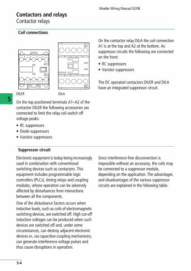
Coil connections
On the top positioned terminals A1–A2 of the contactor DILER the following accessories are connected to limit the relay coil switch off voltage peaks:
• RC suppressors• Diode suppressors• Varistor suppressors
On the contactor relay DILA the coil connection A1 is at the top and A2 at the bottom. As suppressor circuits the following are connected on the front:
• RC suppressors• Varistor suppressors
The DC operated contactors DILER and DILA have an integrated suppressor circuit.
Suppressor circuit
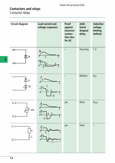
Electronic equipment is today being increasingly used in combination with conventional switching devices such as contactors. This equipment includes programmable logic controllers (PLCs), timing relays and coupling modules, whose operation can be adversely affected by disturbances from interactions between all the components.
One of the disturbance factors occurs when inductive loads, such as coils of electromagnetic switching devices, are switched off. High cut-off induction voltages can be produced when such devices are switched off and, under some circumstances, can destroy adjacent electronic devices or, via capacitive coupling mechanisms, can generate interference voltage pulses and thus cause disruptions in operation.
Since interference-free disconnection is impossible without an accessory, the coils may be connected to a suppressor module, depending on the application. The advantages and disadvantages of the various suppressor circuits are explained in the following table.
DILER DILA
A1
A2
A1
A2
5-4

NotesMoeller Wiring Manual 02/08
5
5-5
Contactors and relaysContactor relays
Moeller Wiring Manual 02/08
5
Circuit diagram Load current and voltage responses
Proof against incorrect connec-tion also for AC
Addi-tional dropout delay
Induction voltage limiting defined
– Very long 1 V
– Medium UZD
yes Short UVDR
yes Short –
D
+
–
D
+
–0
i I0
u U0
0
U
t1 t2
t0 t
t
D
+
–
ZDu
0
i
t1 t2
t0
I0
U0
U
0t
t
VDRu0
i0
U
t1 t2
I0
U0
t
t
R
C0
t00
T1
I0i
u U0
t
t
5-6
Contactors and relaysContactor relays
Moeller Wiring Manual 02/08
5
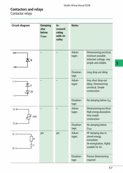
Circuit diagram Damping also below ULIMIT
In-creased rating with cir-cuitry
Notes
– – Advan-tages:
Dimensioning uncritical, minimum possible induction voltage, very simple and reliable
Disadvan-tage:
Long drop-out delay
– – Advan-tages:
Very short drop-out delay. Dimensioning uncritical. Simple construction
Disadvan-tage:
No damping below UZD
– – Advan-tages:
Dimensioning uncritical. High energy absorption. Very simple construction
Disadvan-tage:
No damping below UVDR
yes yes Advan-tages:
HF damping due to stored energy, immediate de-energisation, highly suitable for AC.
Disadvan-tage:
Precise dimensioning required
D
+
–
D
+
–
D
+
–
ZD
VDR
R
C
5-7
Moeller Wiring Manual 02/08
5
Contactors and relaysSmartWire
Connect, don't wire
The heart of a modern machine control system is the PLC (programmable logic controller).
Typically the PLC is mounted in a control panel in a central position of the system. The switchgear is connected with special cables to the input and output terminals of the PLC for the control and return signals.
In a distributed system the connections between the switchgear and the remote input/output system are of a similar type.
The system SmartWire system is used for the connection between the switchgear and the PLC.
The inputs/outputs of the PLC are relocated to the switchgear and connected with a plug-in cable. The switchgear is supplied, as much as possible, by the connection cable. This saves time with control wiring, saves space in the control panel (because cable trunking is no longer requiered) and reduces the necessary inputs/outputs on the PLC.
5-8
Contactors and relaysSmartWire
Moeller Wiring Manual 02/08
5
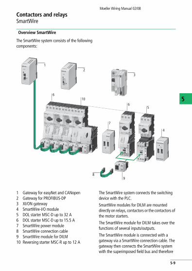
Overview SmartWire
The SmartWire system consists of the following components:
1 Gateway for easyNet and CANopen 2 Gateway for PROFIBUS-DP 3 XI/ON gateway4 SmartWire-I/O module5 DOL starter MSC-D up to 32 A6 DOL starter MSC-D up to 15.5 A7 SmartWire power module8 SmartWire connection cable9 SmartWire module for DILM10 Reversing starter MSC-R up to 12 A
The SmartWire system connects the switching device with the PLC.
SmartWire modules for DILM are mounted directly on relays, contactors or the contactors of the motor starters.
The SmartWire module for DILM takes over the functions of several inputs/outputs.
The SmartWire module is connected with a gateway via a SmartWire connection cable. The gateway then connects the SmartWire system with the superimposed field bus and therefore
I/ON
X
2
8
3
7
9
65
610
4
1
5-9
Contactors and relaysSmartWire
Moeller Wiring Manual 02/08
5
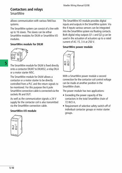
allows communication with various field bus systems.
The SmartWire system can consist of a line with up to 16 slaves. The slaves can be eithar SmartWire modules for DILM or SmartWire I/O modules.
SmartWire module for DILM
The SmartWire module for DILM is fixed directly onto a contactor DILM7 to DILM32, a relay DILA or a motor starter MSC.
The SmartWire module for DILM allows a contactor or a motor starter to be directly controlled from a PLC and the return signals to be monitored. For this purpose the 6 pole SmartWire connection cable is connected via the sockets IN and OUT.
As well as the communication signals a 24 V supply for the contactor coil is also transmitted via the SmartWire connection cable.
SmartWire-I/O module
The SmartWire I/O module provides digital inputs and outputs in the SmartWire system. Via the 4 inputs various sensors can be integrated into the SmartWire system via floating contacts. Both digital relay outputs Q1 c and Q2 g can be used in the actuation of actuators up to a rated current of AC-15, 3 A at 250 V.
SmartWire power module
With a SmartWire power module a second connection for the contactor coil control voltage can be made at another position in the SmartWire chain.
The power module has two applications:
• Exceeding the power capacity of the contactors in the total SmartWire chain of 72 W/3 A,
• Requirement of selective safety switch-off of individual contactor groups or motor starter groups.
5-10
Contactors and relaysSmartWire
Moeller Wiring Manual 02/08
5
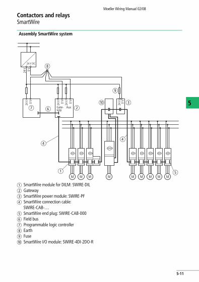
Assembly SmartWire system
a SmartWire module for DILM: SWIRE-DILb Gatewayc SmartWire power module: SWIRE-PFd SmartWire connection cable:
SWIRE-CAB-…e SmartWire end plug: SWIRE-CAB-000f Field busg Programmable logic controllerh Earthi Fusej SmartWire I/O module: SWIRE-4DI-2DO-R
M M MM M MM M M
g bfcj
a
24 V 0 V
24 V 0 V
24 V 0 V
24 V 0 V
24 V 0 V
24 V DC
d
e
d
h
Aux
i
Gate-way
5-11
Contactors and relaysSmartWire
Moeller Wiring Manual 02/08
5
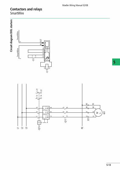
DOL starters
The SmartWire module for DILM controls the contactor so the terminals A1-A2 must not be wired. Also a return signal is fed back to the SmartWire system via the SmartWire module for DILM.
The terminals X3-X4 are supplied with a bridging connection. If in the application electrical interlocking is required the bridge can be removed and the floating contacts connected.
A return signal to the PLC is available at terminals X1-X2. When required, a floating auxiliary contact of the PKZ motor-protective circuit-breaker can be connected here.
a figure, page 5-13
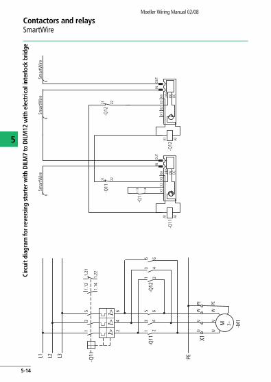
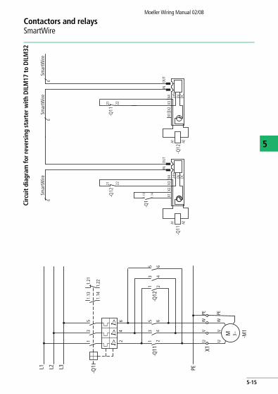
Reversing starters
The reversing starter is assembled from a PKZM0 and two contactors DILM7 to DILM32. A SmartWire module for DILM is mounted on each contactor.The SmartWire module for DILM controls the contactors so the terminals A1-A2 of the contactors must not be wired. Also a return signal will be given back for each to the system SmartWire via the SmartWire module for DILM.Terminals X3-X4 are supplied with a bridging connection. For the electrical interlocking of both contactors this bridge is removed and the auxiliary break contact (21-22) of the other contactor is connected as floating contact.a figure, page 5-14 and
a figure, page 5-15
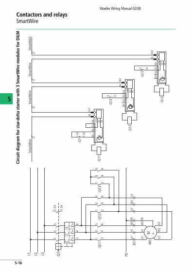
Star-delta starters
with 3 SmartWire modules for DILMThey control the contactors so the terminals A1-A2 of the contactors do not have to be wired. Also a return signal to the system is fed for each of the SmartWire system modules for DILM.
The terminals X3-X4 are supplied with a bridging connection. For the electrical interlocking of both contactors this bridge is removed and the normally closed auxiliary contact (21-22) of the other contactor is connected as floating contact. a figure, page 5-16
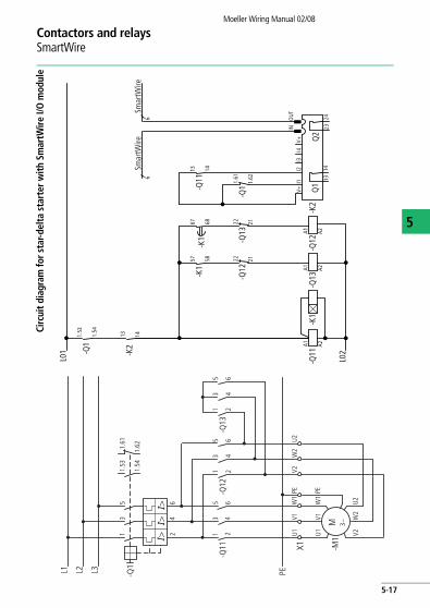
with SmartWire-I/O moduleThe SmartWire I/O module actuates contactor Q11 via digital relay output Q1. The further operation is the same as that of a conventional star-delta starter. The inputs of the SmartWire I/O module are used to implement return signals to the SmartWire system.a figure, page 5-17
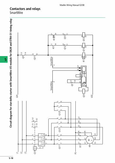
With SmartWire module for DILM and ETR4-51 timing relayThe SmartWire module for DILM controls mains contactor Q11 so that terminals A1-A2 do not have to be wired. A return signal is also fed back to the SmartWire system via the SmartWire module for DILM. The PLC and the changeover between star contactor and delta contactor have the same wiring and function as the conventional star-delta starter assembly.a figure, page 5-18
5-12
Contactors and relaysSmartWire
Moeller Wiring Manual 02/08
5
Circ
uit d
iagr
am D
OL
star
ters
-M1
-Q11
3~M
13
5
24
6
UV
WPE
UV
WPE
-Q1
13
51.
13
1.14
I>I>I>
24
6
PEL1 L2 L3
X1
1.21
1.22
-Q1
1.14
A1 A2
1.13
-Q11
X1X2
X3X4 24
V0V DC
INO
UT66
Smar
tWire
Smar
tWire
5-13
Contactors and relaysSmartWire
Moeller Wiring Manual 02/08
5
Circ
uit d
iagr
am fo
r rev
ersi
ng s
tart
er w
ith D
ILM
7 to
DIL
M12
with
ele
ctric
al in
terlo
ck b
ridge
-M1
-Q12
-Q11
3~M
13
5
24
6
13
5
24
6
UV
WPE
UV
WPE
-Q1
13
51.
13
1.14
1.21
1.22
I>I>I>
24
6
PEL1 L2 L3
X1
-Q1
1.14
A1 A2
1.13
-Q11
X1X2
X3X4 24
V0V DC
INO
UT
-Q11
2221-Q
122221
6Sm
artW
ire
-Q12
X1X2
X3X4 24
V0V DC
INO
UT66
Smar
tWire
Smar
tWire
A1 A2
5-14
Contactors and relaysSmartWire
Moeller Wiring Manual 02/08
5
Circ
uit d
iagr
am fo
r rev
ersi
ng s
tart
er w
ith D
ILM
17 to
DIL
M32
-M1
-Q12
-Q11
3~M
13
5
24
6
13
5
24
6
UV
WPE
UV
WPE
-Q1
13
51.
13
1.14
1.21
1.22
I>I>I>
24
6
PEL1 L2 L3
X1
-Q1
1.14
A1 A2
1.13
-Q11
X1X2
X3X4 24
V0V DC
INO
UT
-Q12
2221-Q
112221
6Sm
artW
ire
-Q12
X1X2
X3X4 24
V0V DC
INO
UT66
Smar
tWire
A1 A2
Smar
tWire
5-15
Contactors and relaysSmartWire
Moeller Wiring Manual 02/08
5
Circ
uit d
iagr
am fo
r sta
r-del
ta s
tart
er w
ith 3
Sm
artW
ire m
odul
es fo
r DIL
M
-M1
-Q12
-Q11
3~M
13
5
24
6-Q13
13
5
24
6
13
5
24
6
U1V1
W1PE
U1V1
W1
V2W2U2
PE
-Q1
13
51.53
1.54
I>I>I>
24
6
V2W2U2
PEL1 L2 L3
X1-Q12
X1X2X3X4 24V 0V DC
INOUT
-Q132221
-Q122221
6SmartWire
6SmartWire
-Q13
X1X2X3X4 24V 0V DC
INOUT6
6SmartWire
SmartWire
-Q11
X1X2X3X4 24V 0V DC
INOUT
-Q11.54
1.53
5-16
Contactors and relaysSmartWire
Moeller Wiring Manual 02/08
5
Circ
uit d
iagr
am fo
r sta
r-del
ta s
tart
er w
ith S
mar
tWire
I/O
mod
ule
-M1
-Q12
-Q11
3~M
13
5
24
6-Q13
13
5
24
6
13
5
24
6
U1V1
W1PE
U1V1
W1
V2W2U2
PE
-Q1
13
51.53
1.54
1.61
1.62
I>I>I>
24
6
V2W2U2
PEL1 L2 L3
X1
L01
-K2
V+I1
I4V+
INO
UT
-Q11
1413
6Sm
artW
ire6
Smar
tWire
-Q1
1.62
1.61
6867
-Q13
2122
-Q12
-K1
5857
-Q12
2122
A2A1
A2A1
A2A1-Q
13
-Q1
1.54
1.53
-K2
1413
-Q11
-K1
L02
I3I2
2423
Q2
1413
Q1
-K1
5-17
Contactors and relaysSmartWire
Moeller Wiring Manual 02/08
5
Circ
uit d
iagr
am fo
r sta
r-del
ta s
tart
er w
ith S
mar
tWire
I/O
mod
ule
for D
ILM
and
ETR
4-51
tim
ing
rela
y
-M1
-Q12
-Q11
3~M
13
5
24
6-Q13
13
5
24
6
13
5
24
6
U1V1
W1PE
U1V1
W1
V2W2U2
PE
-Q1
13
51.53
1.54
1.61
1.62
I>I>I>
24
6
V2W2U2
PEL1 L2 L3
X1
L01
2817
-Q13
2122
-Q12
-Q13-K
1-K
11817
-Q12
2122
A2A1
A2A1
A2A1
-Q1
1.54
1.53
-Q11
1413
L02
66
Smar
tWire
Smar
tWire
-Q11
X1X2
X3X4 24
V0V DC
INO
UT
-Q1
1.62
1.61
-K1
5-18
Contactors and relaysSmartWire
Moeller Wiring Manual 02/08
5
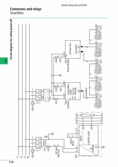
SmartWire system for safety-relevant applications
In most applications an emergency stop function and power-off when a guard or protective door is opened is required in addition to normal operational switching.
Although the SmartWire system is not designed for transmitting safety-relevant signals, it can be laid out to provide safety shutdown functionality using the configuration described below.
In an emergency, the control voltage for the contactor coils can be switched off through the safety relay’s Enable circuit.
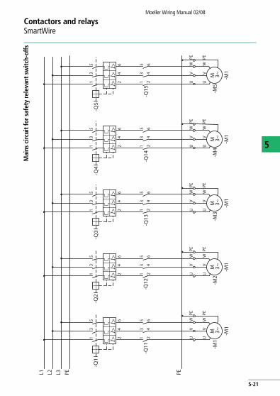
Additional SmartWire power modules can be combined into contactor groups that can be switched off together in an emergency. With this circuit layout, controllers up to EN 954-1 safety category 1 can be set up.
a figure, page 5-20 and a figure, page 5-21
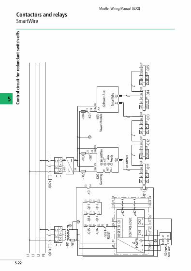
Measures to achieve a higher safety category
In many applications PLCs with safety category 3 or 4 according to EN 954-1 are required.
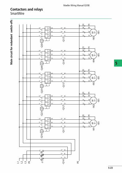
Category 3 controllers can be built with an additional series-connected group contactor upstream of the motor outgoers.
In an emergency, the safety relay isolates the control voltages for both the group contactor and the motor contactors. With this redundant isolation the circuit fulfills the requirements for category 3 PLCs.
a figure, page 5-22 anda figure, page 5-23
5-19
Contactors and relaysSmartWire
Moeller Wiring Manual 02/08
5
Circ
uit d
iagr
am fo
r saf
ety
pow
er-o
ff
L1 L2 PEL3 -Q01
-T01
-F01
I>I>I>
400
0
240
24V
In Out
Out
NET
-S02
RESE
T RESE
T
POW
ER
CONT
ROL-
LOGI
C
2221 Y1A1
A2Y3
Y213 14
-K02
-K01
Gat
eway
-K03
Pow
er-M
odul
e
-K01
13 14
23 24
33 34
41 42
K1 K1
-Q11
X1A1
X2
X3X4
INO
UT
6
A2-Q
12
X1A1
X2
X3X4
INO
UT
A2
6
-Q13
X1A1
X2
X3X4
INO
UT
A2
66
6
-Q14
X1A1
X2
X3X4
INO
UT
A2
6
-Q15
X1A1
X2
X3X4
INO
UT
A2
-Q02
I>I>I>
0V24
V0V
-K01
23 24 24V
0V
-F03
2hH
-F02
-F04
NET
Smar
tWire
Smar
tWire
Smar
tWire
U Au
xRe
ady
InO
ut
Pow
er-A
ux
Aux
-S01
NOT
AUS
21 22
5-20
Contactors and relaysSmartWire
Moeller Wiring Manual 02/08
5
Mai
ns c
ircui
t for
saf
ety
rele
vant
sw
itch-
offs
PEL1 L2 PEL3
-M1
3~M
UV
WPE
UV
WPE
-Q1
13
5
I>I>
I>2
46
-M1
-Q11
13
5
24
6
-M1
3~M
UV
WPE
UV
WPE
-Q2
13
5
I>I>
I>2
46
-M2
-Q12
13
5
24
6
-M1
3~M
UV
WPE
UV
WPE
-Q3
13
5
I>I>
I>2
46
-M3
-Q13
13
5
24
6
-M1
3~M
UV
WPE
UV
WPE
-Q4
13
5
I>I>
I>2
46
-M4
-Q14
13
5
24
6
-M1
3~M
UV
WPE
UV
WPE
-Q5
13
5
I>I>
I>2
46
-M5
-Q15
13
5
24
6
5-21
Contactors and relaysSmartWire
Moeller Wiring Manual 02/08
5
Cont
rol c
ircui
t for
redu
ndan
t sw
itch-
offs
L1 L2 PEL3 -Q01
-T01
-F01
I>I>I>
-S01
NOT
AUS
1.31
1.32
1.21
1.22
-Q15
21 22-Q
1422 21
-Q11
21
400
0
240
24V
In Out
Out
NET
22
-Q16
21 22
-S02
RESE
T
RESE
T
POW
ERCH
1CH
2
CONT
ROL-
LOGI
C
–+
–+
+
13 14 S34
A1A2
-Q13
22 21-Q
1221 22
S35
S31
S22
S12
S12
S21
S33
13 14
-K01
-K02
Gat
eway
-K03
Pow
er-M
odul
e
-Q16
13 14-K
0123 24
23 24
33 34
A1 A2
K1 K1
-Q11
X1A1
X2
X3X4
INO
UT
6
A2-Q
12
X1A1
X2
X3X4
INO
UT
A2
6
-Q13
X1A1
X2
X3X4
INO
UT
A2
66
6
-Q14
X1A1
X2
X3X4
INO
UT
A2
6
-Q15
X1A1
X2
X3X4
INO
UT
A2
-Q02
I>I>I>
0V24
V0V
-K01
33 34 24V
0V
-F02
2hH -F
03-F
04
NET
Smar
tWire
Smar
tWire
U Au
xRe
ady
InO
ut
Pow
er-A
ux
Aux
Smar
tWire
5-22
Contactors and relaysSmartWire
Moeller Wiring Manual 02/08
5Mai
n ci
rcui
t for
redu
ndan
t sw
itch-
offs
PEL1 L2 PEL3
-M1
3~M
UV
WPE
UV
WPE
-Q1
13
5
I>I>
I>2
46
-M1
-Q11
13
5
24
6
-M1
3~M
UV
WPE
UV
WPE
-Q2
13
5
I>I>
I>2
46
-M2
-Q12
13
5
24
6
-M1
3~M
UV
WPE
UV
WPE
-Q3
13
5
I>I>
I>2
46
-M3
-Q13
13
5
24
6
-M1
3~M
UV
WPE
UV
WPE
-Q4
13
5
I>I>
I>2
46
-M4
-Q14
13
5
24
6
-M1
3~M
UV
WPE
UV
WPE
-Q5
13
5
I>I>
I>2
46
-M5
-Q15
13
5
24
6-Q
16
-F1
13
5
24
6
5-23
Moeller Wiring Manual 02/08
5
Contactors and relaysContactors DIL, overload relays Z
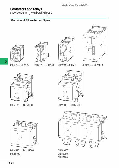
Overview of DIL contactors, 3-pole
DILM7 … DILM15 DILM17 … DILM38 DILM40 …DILM72 DILM80 … DILM170
DILM185 … DILM250 DILM300 … DILM500
DILM580 … DILM1000DILH1400
DILM1600DILH2000DILH2200
5-24
Contactors and relaysContactors DIL, overload relays Z
Moeller Wiring Manual 02/08
5
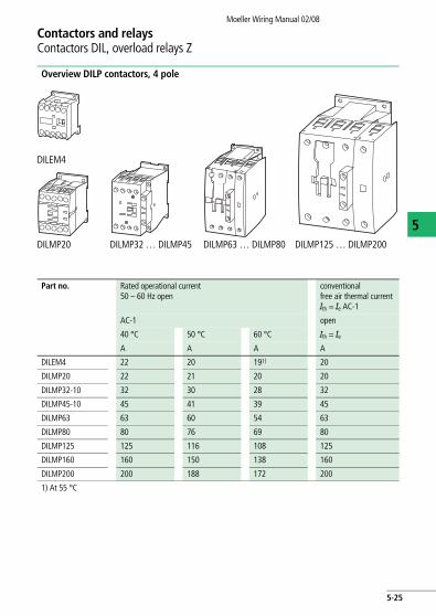
Overview DILP contactors, 4 pole
DILEM4
DILMP20 DILMP32 … DILMP45 DILMP63 … DILMP80 DILMP125 … DILMP200
Part no. Rated operational current 50 – 60 Hz open
conventional free air thermal current Ith = Ie AC-1
AC-1 open
40 °C 50 °C 60 °C Ith = IeA A A A
DILEM4 22 20 191) 20
DILMP20 22 21 20 20
DILMP32-10 32 30 28 32
DILMP45-10 45 41 39 45
DILMP63 63 60 54 63
DILMP80 80 76 69 80
DILMP125 125 116 108 125
DILMP160 160 150 138 160
DILMP200 200 188 172 200
1) At 55 °C
5-25
Contactors and relaysContactors DIL, overload relays Z
Moeller Wiring Manual 02/08
5
Part no. Auxiliary contact blocks
For surface mounting
For side mounting
DILEEM 02DILEM11DILEM22DILEM
–
DILEM
DILM7 DILA-XHI(V)…DILM32-XHI…
–
DILM9
DILM12
DILM15
DILM17 DILM32-XHI11-S
DILM25
DILM32
DILM32
DILM40 DILM150-XHI(V)…
DILM1000-XHI(V)…
DILM50
DILM65
DILM72
DILM80
DILM95
DILM115
DILM150
DILM170
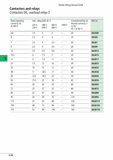
Rated operating current Ie [A] At 400 V
max. rating [kW] AC-3 Conventional free air thermal current Ith =Ie [A]AC-1 at 60 °C
Part no.
220 V,230 V
380 V,400 V
660 V,690 V
1000 V
6.6 1.5 3 3 – 20 DILEEM
9 2.2 4 4 – 20 DILEM
7 2.2 3 3.5 – 20 DILM7
9 2.5 4 4.5 – 20 DILM9
12 3.5 5.5 6.5 – 20 DILM12
15.5 4 7.5 7 – 20 DILM15
17 5 7.5 11 – 35 DILM17
25 7.5 11 14 – 40 DILM25
32 10 15 17 – 40 DILM32
38 11 18.5 17 – 40 DILM38
40 12.5 18.5 23 – 50 DILM40
50 15.5 22 30 – 65 DILM50
65 20 30 35 – 80 DILM65
72 25 37 35 – 80 DILM72
80 25 37 63 – 90 DILM80
95 30 45 75 – 110 DILM95
115 37 55 90 – 130 DILM115
150 48 75 96 – 160 DILM150
170 52 90 140 – 185 DILM170
5-26
Contactors and relaysContactors DIL, overload relays Z
Moeller Wiring Manual 02/08
Conventional free air thermal current Ith =Ie [A]AC-1 at 60 °C
Part no.
V, 1000 V
– 20 DILEEM
– 20 DILEM
– 20 DILM7
– 20 DILM9
– 20 DILM12
– 20 DILM15
– 35 DILM17
– 40 DILM25
– 40 DILM32
– 40 DILM32
– 50 DILM40
– 65 DILM50
– 80 DILM65
– 80 DILM72
– 90 DILM80
– 110 DILM95
– 130 DILM115
– 160 DILM150
– 185 DILM170
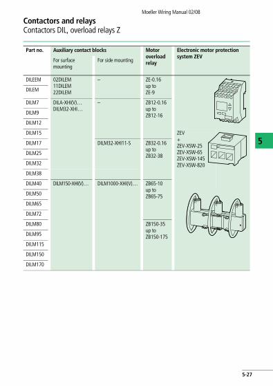
5
Part no. Auxiliary contact blocks Motor overload relay
Electronic motor protection system ZEV
For surface mounting
For side mounting
DILEEM 02DILEM11DILEM22DILEM
– ZE-0.16up toZE-9DILEM
DILM7 DILA-XHI(V)…DILM32-XHI…
– ZB12-0.16up toZB12-16DILM9
DILM12
DILM15 ZEV+ZEV-XSW-25ZEV-XSW-65ZEV-XSW-145ZEV-XSW-820
DILM17 DILM32-XHI11-S ZB32-0.16up toZB32-38DILM25
DILM32
DILM38
DILM40 DILM150-XHI(V)… DILM1000-XHI(V)… ZB65-10up toZB65-75DILM50
DILM65
DILM72
DILM80 ZB150-35up toZB150-175DILM95
DILM115
DILM150
DILM170
5-27
Contactors and relaysContactors DIL, overload relays Z
Moeller Wiring Manual 02/08
5
Part no. Auxiliary contact blocks
For surface mounting
For side mounting
DILM185 – DILM1000-XHI…
DILM225
DILM250
DILM300
DILM400
DILM500
DILM580
DILM650
DILM750
DILM820
DILM1000
DILM1600
DILH1400
DILH2000
DILH2200
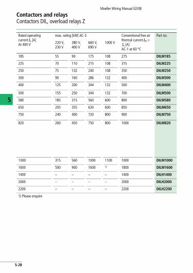
Rated operating current Ie [A] At 400 V
max. rating [kW] AC-3 Conventional free air thermal current Ith =Ie [A]AC-1 at 60 °C
Part no.
220 V,230 V
380 V,400 V
660 V,690 V
1000 V
185 55 90 175 108 275 DILM185
225 70 110 215 108 315 DILM225
250 75 132 240 108 350 DILM250
300 90 160 286 132 400 DILM300
400 125 200 344 132 500 DILM400
500 155 250 344 132 700 DILM500
580 185 315 560 600 800 DILM580
650 205 355 630 600 850 DILM650
750 240 400 720 800 900 DILM750
820 260 450 750 800 1000 DILM820
1000 315 560 1000 1100 1000 DILM1000
1600 500 900 1600 1) 1800 DILM1600
1400 – – – – 1400 DILH1400
2000 – – – – 2000 DILH2000
2200 – – – – 2200 DILH2200
1) Please enquire
5-28
Contactors and relaysContactors DIL, overload relays Z
Moeller Wiring Manual 02/08
Conventional free air thermal current Ith =Ie [A]AC-1 at 60 °C
Part no.
V, 1000 V
108 275 DILM185
108 315 DILM225
108 350 DILM250
132 400 DILM300
132 500 DILM400
132 700 DILM500
600 800 DILM580
600 850 DILM650
800 900 DILM750
800 1000 DILM820
1100 1000 DILM1000
1) 1800 DILM1600
– 1400 DILH1400
– 2000 DILH2000
– 2200 DILH2200
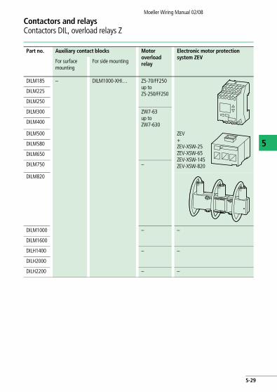
5
Part no. Auxiliary contact blocks Motor overload relay
Electronic motor protection system ZEV
For surface mounting
For side mounting
DILM185 – DILM1000-XHI… Z5-70/FF250up toZ5-250/FF250DILM225
DILM250
DILM300 ZW7-63up toZW7-630DILM400
DILM500 ZEV+ZEV-XSW-25ZEV-XSW-65ZEV-XSW-145ZEV-XSW-820
DILM580
DILM650
DILM750 –
DILM820
DILM1000 – –
DILM1600
DILH1400 – –
DILH2000
DILH2200 – –
5-29
Moeller Wiring Manual 02/08
5
Contactors and relaysContactors DIL
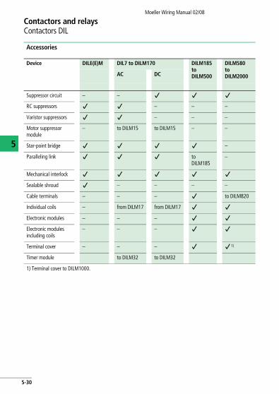
Accessories
Device DILE(E)M DIL7 to DILM170 DILM185 to DILM500
DILM580 to DILM2000AC DC
Suppressor circuit – – j j j
RC suppressors j j – – –
Varistor suppressors j j – – –
Motor suppressor module
– to DILM15 to DILM15 – –
Star-point bridge j j j j –
Paralleling link j j j to DILM185
–
Mechanical interlock j j j j j
Sealable shroud j – – – –
Cable terminals – – – j to DILM820
Individual coils – from DILM17 from DILM17 j j
Electronic modules – – – j j
Electronic modules including coils
– – – j j
Terminal cover – – – j j 1)
Timer module to DILM32 to DILM32
1) Terminal cover to DILM1000.
5-30
Contactors and relaysContactors DIL
Moeller Wiring Manual 02/08
5
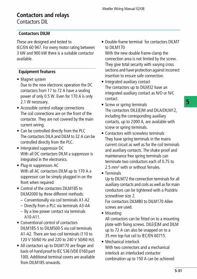
Contactors DILM
These are designed and tested to IEC/EN 60 947. For every motor rating between 3 kW and 900 kW there is a suitable contactor available.
Equipment features
• Magnet systemDue to the new electronic operation the DC contactors from 17 to 72 A have a sealing power of only 0.5 W. Even for 170 A is only 2.1 W necessary.
• Accessible control voltage connections The coil connections are on the front of the contactor. They are not covered by the main current wiring.
• Can be controlled directly from the PLC The contactors DILA and DILM to 32 A can be controlled directly from the PLC.
• Intergrated suppressor DCWith all DC contactors DILM a suppressor is integrated in the electronics.
• Plug-in suppressors ACWith all AC contactors DILM up to 170 A a suppressor can be simply plugged in on the front when required.
• Control of the contactors DILM185 to DILM2000 by three different methods: – Conventionally via coil terminals A1-A2– Directly from a PLC via terminals A3-A4– By a low power contact via terminals
A10-A11.• Conventional control of contactors
DILM185-S to DILM500-S via coil terminals A1-A2. There are two coil terminals (110 to 120 V 50/60 Hz and 220 to 240 V 50/60 Hz).
• All contactors up to DILM170 are finger and back-of-hand proof to IEC 536 (VDE 0160 part 100). Additional terminal covers are available from DILM185 onwards.
• Double-frame terminal for contactors DILM7 to DILM170With the new double frame-clamp the connection area is not limited by the screw. They give total security with varying cross sections and have protection against incorrect insertion to ensure safe connection.
• Integrated auxiliary contact The contactors up to DILM32 have an integrated auxiliary contact as N/O or N/C contact.
• Screw or spring terminals The contactors DILE(E)M and DILA/DILM12, including the corresponding auxiliary contacts, up to 2000 A, are available with screw or spring terminals.
• Contactors with screwless terminals They have spring terminals in the mains current circuit as well as for the coil terminals and auxiliary contacts. The shake proof and maintenance free spring terminals can terminate two conductors each of 0.75 to 2.5 mm2 with or without ferrules.
• TerminalsUp to DILM72 the connection terminals for all auxiliary contacts and coils as well as for main conductors can be tightened with a Pozidriv screwdriver size 2.For contactors DILM80 to DILM170 Allen screws are used.
• Mounting All contactors can be fitted on to a mounting plate with fixing screws. DILE(E)M and DILM up to 72 A can also be snapped on to a 35 mm top-hat rail to IEC/EN 60715.
• Mechanical interlock With two connectors and a mechanical interlock an interlocked contactor combination up to 150 A can be achieved
5-31
Contactors and relaysContactors DIL
Moeller Wiring Manual 02/08
5
without extra space requirement. The mechanical interlock ensures that both connected contactors cannot be similtaneously be operated. Even with a mechanical shock the contacts of both contactors cannot close similtaneously.
In addition to individual contactors, complete contactor combinations are also available from Moeller:
• DIUL reversing contactors from 3 to 75 kW/400 V
• SDAINL star-delta starters from 5.5 to 132 kW/400 V
xStart DC-actuated contactors
The market for DC actuated contactors is growing due to the increasing use of electronics. Whilst AC contactors were used 20 years ago with additional resistors and specially wound DC coils with a lot of copper were used till recently, the next quantum leap has started. Electronic components are now in use for the drives of DC actuated contactors.
The xStart contactor series DILM7 to DILM170 has been particularly optimized in the development of DC actuated contactors. The DILM17 to DILM170 DC contactors are no longer switched on or off in the conventional way using a coil but by means of an electronic unit.
The integration of electronics in the contactor drives makes different technical features possible which enable the contactors to offer outstanding performance in their daily use.
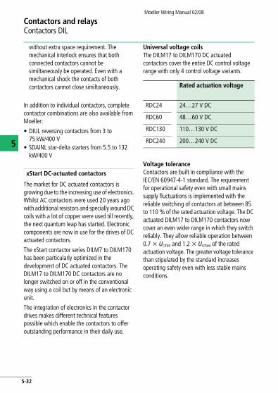
Universal voltage coilsThe DILM17 to DILM170 DC actuated contactors cover the entire DC control voltage range with only 4 control voltage variants.
Voltage toleranceContactors are built in compliance with the IEC/EN 60947-4-1 standard. The requirement for operational safety even with small mains supply fluctuations is implemented with the reliable switching of contactors at between 85 to 110 % of the rated actuation voltage. The DC actuated DILM17 to DILM170 contactors now cover an even wider range in which they switch reliably. They allow reliable operation between 0.7 x Ucmin and 1.2 x Ucmax of the rated actuation voltage. The greater voltage tolerance than stipulated by the standard increases operating safety even with less stable mains conditions.
Rated actuation voltage
RDC24 24…27 V DC
RDC60 48…60 V DC
RDC130 110…130 V DC
RDC240 200…240 V DC
5-32
Contactors and relaysContactors DIL
Moeller Wiring Manual 02/08
5
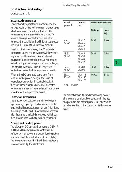
Integrated suppressor Conventionally operated contactors generate voltage peaks at the coil to current change dI/dt which can have a negative effect on other components in the same control circuit. To prevent damage, contactor coils are often connected in parallel with additional suppressor circuits (RC elements, varistors or diodes).
Thanks to their electronics, the DC actuated contactors DILM17 to DILM170 switch without any effect on the network. An additional suppressor is therefore unnecessary since the coils do not generate any external overvoltages. The otherDILM7 to DILM15 DC operated contactors have a built-in suppressor circuit.
When using DC operated contactors from Moeller in the project design, the issue of overvoltage protection in control circuits is therefore unnecessary since all DC operated contactors are free of system disturbance or are provided with a suppressor circuit.
Contactor dimensionsThe electronic circuit provides the coil with a high making capacity, which it reduces to the required holding power after startup. This allows the design of AC- and DC-operated contactors with the same physical dimensions, which can then also be used with the same accessories.
Pick-up and holding powerThe pickup of DC-operated contactors DILM17 to DILM170 is electronically controlled. A sufficiently high power is provided for the pickup to ensure that the contactor switches reliably. The low power needed to hold the contactor is also controlled by the electronics.
For project design, the reduced sealing power also means a considerable reduction in the heat dissipation in the control panel. This allows side by side mounting of the contactors in the control panel.
Rated power 1)
Contac-tor
Power consumption
Pick-up Hold-ing
7.5…15 kW
DILM17DILM25DILM32DILM38
12 W 0.5 W
18.5…37 kW
DILM40DILM50DILM65DILM72
24 W 0.5 W
37…45 kW
DILM80DILM95
90 W 1.3 W
55…90 kW
DILM115DILM150DILM170
149 W 2.1 W
1) AC-3 at 400 V
5-33
Contactors and relaysContactors DIL
Moeller Wiring Manual 02/08
5
Applications
The three-phase motor dominates the electric motor sector. Apart from individual low-power drives, which are often switched directly by hand, most motors are controlled using contactors and contactor combinations. The power rating in kilowatts (kW) or the current rating in amperes (A) is therefore the critical feature for correct contactor selection.
Physical motor design means that rated currents for the same rating sometimes differ widely. Furthermore it determines the ratio of the transient peak current and the locked-rotor current to the rated operational current (Ie).
Switching electrical heating installations, lighting fittings, transformers and power factor correction installations, with their typical individual characteristics, increases the wide range of different uses for contactors.
The switching frequency can vary greatly in every application. The difference can be, for example, from less than one operation per day up to a thousand operations or more per hour. Quite often, in the case of motors, a high switching frequency coincides with inching and plugging duty.
Contactors are actuated manually or automatically, using various types of command devices, depending on the travel, time, pressure or temperature. Any interrelationships required between a number of contactors can easily be produced by means of interlocks via their auxiliary contacts.
The auxiliary contact of the contactor DILM can be used as mirror contact to IEC/EN 60947-4-1 Appendix F to show the condition of the main contacts. A mirror contact is a normally closed contact that cannot be similtaneously closed with the normally open main contacts.
Other applications• Capacitor contactors for power factor
compensation DILK for 12.5 to 50 kvar/400 V.• Lighting contactors DILL for 12 to 20 A/400 V
(AC-5a) or 14 to 27 A/400 V (AC-5b).
5-34
Moeller Wiring Manual 02/08
Contactors and relaysOverload relays Z
5
Motor protection using Z thermal overload relays
Overload relays are included in the group of current-dependent protective devices. They monitor the temperature of the motor winding indirectly via the current flowing in the supply cables, and offer proven and cost-efficient protection from destruction as a result of:
• Non starting,• Overload, • Phase-failure.
Overload relays operate by using the characteristic changes of shape and state of the bimetal when subjected to heating. When a specific temperature is reached, they operate an auxiliary switch. The heating is caused by resistances through which the motor current flows. The equilibrium between the reference
and actual value occurs at various temperatures depending on the magnitude of the current.
Tripping occurs when the reference temperature is reached. The tripping delay depends on the magnitude of the current and preloading of the relay. Whatever the current, the relay must trip out before the motor insulation is endangered, which is why EN 60947 states maximum response times. To prevent nuisance tripping, minimum times are also given for the limit current and locked-rotor current.
Phase-failure sensitivity
Overload relays Z offer, due to their design, an effective protection against phase failure. They have phase failure sensitivity to IEC 947-4-1 and VDE 0660 part 102 and therefore can also provide protection for EEx e motors (a following diagramms).
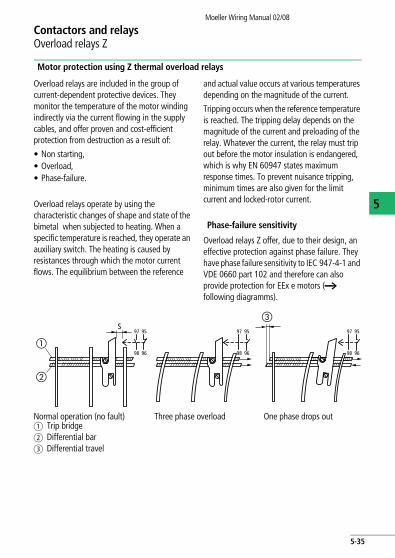
Normal operation (no fault) Three phase overload One phase drops outa Trip bridge b Differential barc Differential travel
97S
95
98 96
97 95
98 96
97 95
98 96
�
�
�
5-35
Contactors and relaysOverload relays Z
Moeller Wiring Manual 02/08
5
When the bimetallic strips in the main current section of the relay deflect as a result of three-phase motor overloading, all three act on a trip bar and a differential bar. A shared trip lever switches over the auxiliary contact when the limits are reached. The trip and differential bars lie against the bimetallic strips with uniform pressure. If, in the event of phase failure for instance, one bimetallic strip does not deflect (or recover) as strongly as the other two, then the trip and differential bars will cover different
distances. This differential movement is converted in the device by a step-up mechanism into a supplementary tripping movement, and thus accelerates the tripping action.
Design note a section "Motor protection in special applications", page 8-8;
Further information to motor protection a section "All about Motors", page 8-1.
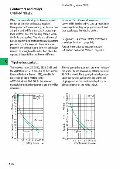
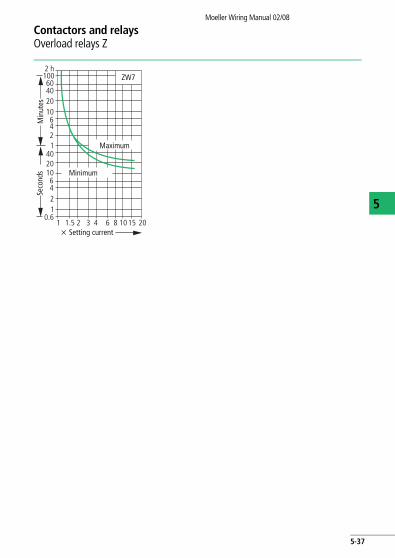
Tripping characteristics
The overload relays ZE, ZB12, ZB32, ZB65 and the ZB150 up to 150 A are, due to the German Physical/Technical Bureau (PTB), suitable for protection of EEx e-motors to the ATEX-Guidelines 94/9 EG. In the relevant manual all tripping characteristics are printed for all currents.
These tripping characteristics are mean values of the scatter bands at an ambient temperature of 20 °C from cold. The tripping time is dependant upon the current. When units are warm, the tripping delay of the overload relay drops to about a quarter of the value shown.
2h100604020106421
4020106421
0.6
ZB12, ZB32, ZB65, ZE
1 1.5 2 3 4 6 8 10 15 20x Setting current
2-phaseSeco
nds
Min
utes
3-phase
2h100604020106421
4020106421
0.6
ZB150
6 8 1015 20 3 41 1.5 2x Setting current
2-phaseSeco
nds
Min
utes
3-phase
5-36
Contactors and relaysOverload relays Z
Moeller Wiring Manual 02/08
5
2 h100604020106421
4020106421
1 1.5 2 3 4 6 8 10 15 200.6
ZW7
Min
utes
Seco
nds
x Setting current
Minimum
Maximum
5-37
Moeller Wiring Manual 02/08
5
Contactors and relaysZEV electronic motor-protective system
Operating principle and control
Like overload relays operating on the bimetallic strip principle, electronic motor-protective relays are current-dependent protective devices.
The acquisition of the actual flowing motor current in the three external conductors of the motor connections is with motor protection system ZEV with seperate push-through sensors or a sensor belt. These are combined with an evaluation unit so that seperate arrangement of the current sensor and the evaluation unit is possible.
The current sensor is based on the Rogowski principle from the measurement technology. The sensor belt has no iron core, unlike a current transformer, therefore it doesn´t become saturated and can measure a very wide current range.
Due to this inductive current detection, the conductor cross-sections used in the load circuit have no influence on the tripping accuracy. With electronic motor-protective relays, it is possible to set higher current ranges than is possible with electromechanical thermal overload relays. In the ZEV System, the entire protected range from 1 to 820 A is covered using only an evaluator.
The ZEV electronic motor-protective system carries out motor protection both by means of indirect temperature measurement via the current and also by means of direct temperature measurement in motors with thermistors.
Indirectly, the motor is monitored for overload, phase failure and unbalanced current consumption.
With direct measurement, the temperature in the motor winding is detected by means of one or more PTC thermistors. In the event of excessive temperature rise, the signal is passed to the tripping unit and the auxiliary contacts are actuated. A reset is not possible until the thermistors cool to less than the response temperature. The built-in thermistor connection allows the relay to be used as complete motor protection.
In addition, the relay protects the motor against earth faults. Small currents flow out even in the event of minor damage to the motor winding insulation. These earth faults currents are registered on an external summation current transformer, which adds together the currents in the phases, evaluats them and reports earth-fault currents to the microprocessor in the relay.
Selecting one of the eight tripping classes (CLASS) allows the motor to be protected to be adapted from normal to extended starting conditions. This allows the thermal reserves of the motor to be used safely.
The motor-protective relay is supplied with an auxiliary voltage. The evaluator has a multi-voltage version, which enables all voltages between 24 V and 240 V AC or DC to be applied as supply voltage. The devices have monostable behaviour; they trip out as soon as the supply voltage fails.
5-38
Contactors and relaysZEV electronic motor-protective system
Moeller Wiring Manual 02/08
5
In addition to the usual N/C contact (95-96) and the N/O contact (97-98) for overload relays the motor protection relay ZEV is equipped with a programmable N/O contact (07-08) and a programmable N/C contact (05-06). The above mentioned, usual contacts react directly via thermistors or indirectly via the current, to the detected temperature rise of the motor, including phase-failure sensitivity.
The programmable contacts can be assigned to various signals, such as
• Earth-fault, • Pre-warning at 105 % thermal overload,• Separate indication of thermistor tripping • Internal device faultThe function assignment is menu-guided using a display. The motor current is entered without tools using the keypad, and can be clearly verified on the display.
In addition the display allows a differential diagnosis of tripping causes, and therefore a faster error handling is possible.
Tripping in the event of a 3 pole balanced overload at x-times the set current takes place within the time specified by the tripping class. The tripping delay in comparison with the cold state is reduced as a function of the preloading of the motor. Very good tripping accuracy is achieved and the tripping delays are constant over the entire setting range.
If the motor current imbalance exceeds 50 %, the relay trips after 2.5 s.
The accredition exists for overload protection of explosion proof motors of the explosion protection “increased safety” EEx e to Directive 94/9/EC as well as the report of the German Physical/Technical Bureaux (PTB report ) (EG-Prototype test certificate number PTB 01 ATEX 3233). Further information can be found in the manual AWB2300-1433G “Motor protection system ZEV, overload monitoring of motors in EEx e areas”.
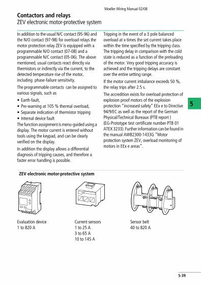
ZEV electronic motor-protective system
Evaluation device1 to 820 A
Current sensors 1 to 25 A3 to 65 A10 to 145 A
Sensor belt40 to 820 A
5-39
Contactors and relaysZEV electronic motor-protective system
Moeller Wiring Manual 02/08
5
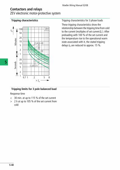
Tripping characteristics Tripping characteristics for 3 phase loads
These tripping characteristics show the relationship between the tripping time from cold to the current (multiples of set current IE ). After preloading with 100 % of the set current and the temperature rise to the operational warm state associated with it, the stated tripping delays tA are reduced to approx. 15 %.
Tripping limits for 3 pole balanced load
Response time
< 30 min. at up to 115 % of the set current> 2 h at up to 105 % of the set current from
cold
20
CLASS 40
25
15
CLASS 510
tA100
50
20
10
5
2
1
20
10
5
2
10.7 1 2 5 8
3035
x Ie
ZEV
Min
utes
Seco
nds
5-40
Contactors and relaysZEV electronic motor-protective system
Moeller Wiring Manual 02/08
5
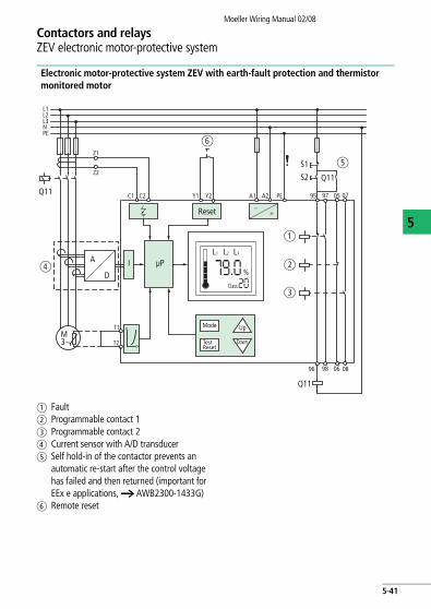
Electronic motor-protective system ZEV with earth-fault protection and thermistor monitored motor
a Faultb Programmable contact 1c Programmable contact 2d Current sensor with A/D transducer e Self hold-in of the contactor prevents an
automatic re-start after the control voltage has failed and then returned (important for EEx e applications, a AWB2300-1433G)
f Remote reset
L1L2L3N
96 06 0898
95 05 07A1 A2Y1 Y2 PEC1
Z1
Z2
C2
T2
T1 <
>
M3~
Reset
S1
S2 Q11
Q11
~=
97
I µP
Mode
Class
TestReset
Up
Down
L1
A
D
L2 L3
%
PE
Q11
a
f
d
e
b
c
5-41
Contactors and relaysZEV electronic motor-protective system
Moeller Wiring Manual 02/08
5
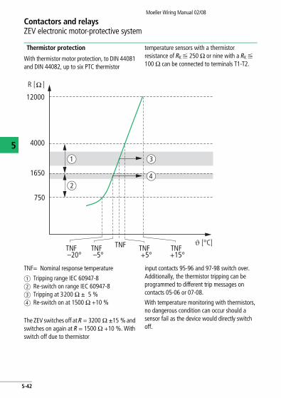
Thermistor protection
With thermistor motor protection, to DIN 44081 and DIN 44082, up to six PTC thermistor
temperature sensors with a thermistor resistance of RK F 250 O or nine with a RK F 100 O can be connected to terminals T1-T2.
TNF= Nominal response temperature
a Tripping range IEC 60947-8b Re-switch on range IEC 60947-8c Tripping at 3200 O g 5 %d Re-switch on at 1500 O +10 %
The ZEV switches off at R = 3200 O g15 % and switches on again at R = 1500 O +10 %. With switch off due to thermistor
input contacts 95-96 and 97-98 switch over. Additionally, the thermistor tripping can be programmed to different trip messages on contacts 05-06 or 07-08.
With temperature monitoring with thermistors, no dangerous condition can occur should a sensor fail as the device would directly switch off.
TNF–20°
TNFTNF–5°
750
4000
12000
1650
TNF+5°
TNF+15°
a
b
c
d
R [ ]
i [°C]
5-42
Contactors and relaysZEV electronic motor-protective system
Moeller Wiring Manual 02/08
5
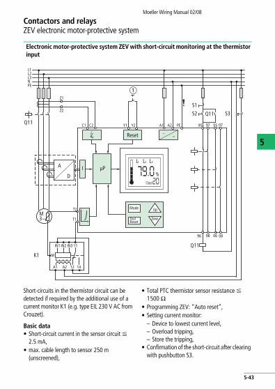
Electronic motor-protective system ZEV with short-circuit monitoring at the thermistor input
Short-circuits in the thermistor circuit can be detected if required by the additional use of a current monitor K1 (e.g. type EIL 230 V AC from Crouzet).
Basic data • Short-circuit current in the sensor circuit F
2.5 mA,• max. cable length to sensor 250 m
(unscreened),
• Total PTC thermistor sensor resistance F 1500 O
• Programming ZEV: “Auto reset”,• Setting current monitor:
– Device to lowest current level,– Overload tripping, – Store the tripping,
• Confirmation of the short-circuit after clearing with pushbutton S3.
a
L1L2L3N
96 06 0898
95 05 07A1 A2Y1 Y2 PEC1
Z1
Z2
C2
T1
T2 <
>
M3~
Reset
S1
S2 Q11
Q11
~=
97
I µP
Mode
Class
TestReset
Up
Down
L1
A
D
L2 L3
%
PE
IN1
M
IN2 IN3 11
A1 A2 12 14
S3
Q11
K1
5-43
Contactors and relaysZEV electronic motor-protective system
Moeller Wiring Manual 02/08
5
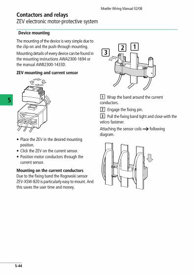
Device mounting
The mounting of the device is very simple due to the clip-on and the push-through mounting.
Mounting details of every device can be found in the mounting instructions AWA2300-1694 or the manual AWB2300-1433D.
ZEV mounting and current sensor
• Place the ZEV in the desired mounting position.
• Click the ZEV on the current sensor. • Position motor conductors through the
current sensor.
Mounting on the current conductorsDue to the fixing band the Rogowski sensor ZEV-XSW-820 is particularly easy to mount. And this saves the user time and money.
Wrap the band around the current conductors.
Engage the fixing pin.
Pull the fixing band tight and close with the velcro fastener.
Attaching the sensor coils a following diagram.
1123
1
2
3
5-44
Moeller Wiring Manual 02/08
Contactors and relaysThermistor machine protection device EMT6
5
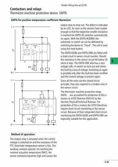
EMT6 for positive temperature coefficient thermistor
Method of operation
The output relay is actuated when the control voltage is switched on and the resistance of the PTC thermistor temperature sensor is low. The auxiliary contacts operate. On reaching the nominal actuation temperature (NAT), the sensor resistance becomes high and causes the
output relay to drop out. The defect is indicated by an LED. As soon as the sensors have cooled enough so that the respective smaller resistance is reached the EMT6-(K) switches automatically on again. With the EMT6-(K)DB(K) the automatic re-switch on can be defeated by switching the device to “Hand”. The unit is reset using the reset button.
The EMT6-K(DB) and EMT6-DBK are fitted with a short-cicuit in sensor circuit monitor. Should the resistance in the sensor circuit fall below 20 ohms it trips. The EMT6-DBK also has a zero voltage safe, re-switch on lock-out and stores the fault by a loss of voltage. Switching on again is possible only after the fault has been rectified and the control voltage is present again.
Since all the units use the closed-circuit principle, they also respond to a broken wire in the sensor circuit.
The thermistor machine protection relays EMT6… are accredited for protection of EEx e motors to ATEX Directive 94/9 EG by the German Physical/Technical Bureaux. For protection of EEx e motors the ATEX Directives require short-circuit monitoring in the sensor circuit. Because of their integrated short-circuit monitoring the EMT6-K(DB) and EMT6-DBK are especially suitable for this application.
US
A1
A2
PTC
N
T1 T2
21 13
22 14
L
Power Tripped
US
A1
A2
PTC
N
T1 T2
21Y2Y1 13
22 14
L
+24
VPower Tripped
Rese
t
5-45
Contactors and relaysThermistor machine protection device EMT6
Moeller Wiring Manual 02/08
5
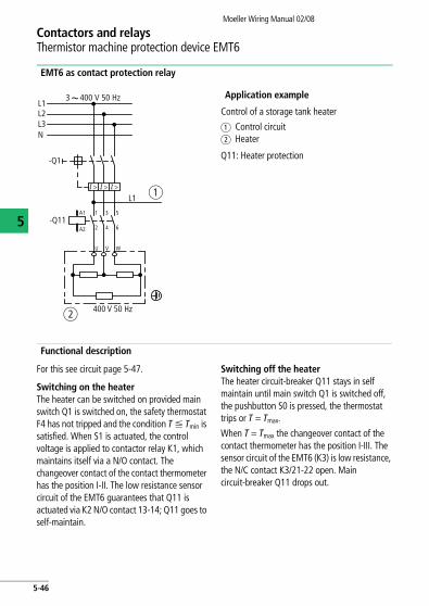
EMT6 as contact protection relay
Application example
Control of a storage tank heater
a Control circuitb Heater
Q11: Heater protection
Functional description
For this see circuit page 5-47.
Switching on the heaterThe heater can be switched on provided main switch Q1 is switched on, the safety thermostat F4 has not tripped and the condition T F Tmin is satisfied. When S1 is actuated, the control voltage is applied to contactor relay K1, which maintains itself via a N/O contact. The changeover contact of the contact thermometer has the position I-II. The low resistance sensor circuit of the EMT6 guarantees that Q11 is actuated via K2 N/O contact 13-14; Q11 goes to self-maintain.
Switching off the heaterThe heater circuit-breaker Q11 stays in self maintain until main switch Q1 is switched off, the pushbutton S0 is pressed, the thermostat trips or T = Tmax.
When T = Tmax the changeover contact of the contact thermometer has the position I-III. The sensor circuit of the EMT6 (K3) is low resistance, the N/C contact K3/21-22 open. Main circuit-breaker Q11 drops out.
L13 400 V 50 Hz
L2L3N
-Q1
L1
-Q11A2
A1 1 3 5
2 4 6
U V W
I > I > I >
400 V 50 Hzb
a
5-46
Contactors and relaysThermistor machine protection device EMT6
Moeller Wiring Manual 02/08
5
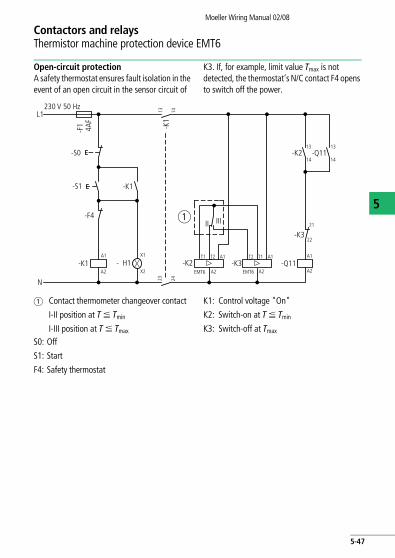
Open-circuit protectionA safety thermostat ensures fault isolation in the event of an open circuit in the sensor circuit of
K3. If, for example, limit value Tmax is not detected, the thermostat’s N/C contact F4 opens to switch off the power.
a Contact thermometer changeover contact
I-II position at T F Tmin
I-III position at T F Tmax
K1: Control voltage "On"
K2: Switch-on at T F Tmin
K3: Switch-off at Tmax
S0: Off
S1: Start
F4: Safety thermostat
230 V 50 Hz
-S0
-S1
-F4
-K1
-K2 -Q11
-Q11-K21313
1414
-K3
-K3EMT6 EMT6A2
T1 T2 A1 T2 T1 A1
A2
A1
21
22
A2-K1
N
A1 X1
X2A2- H1
II III
L1
-F1 4A
F
-K1
1424
1323
a
5-47
Moeller Wiring Manual 02/08
5
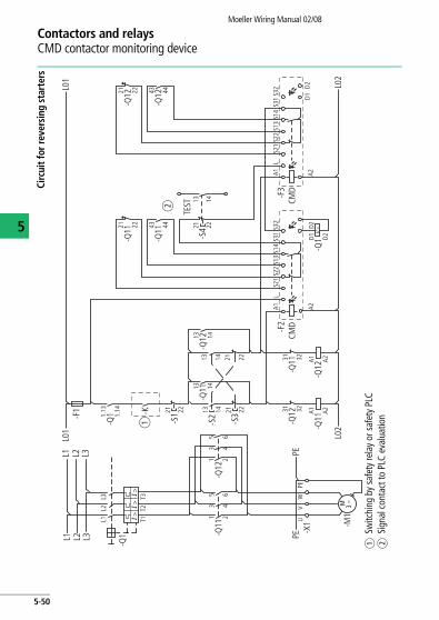
Contactors and relaysCMD contactor monitoring device
Operating principle
The CMD (Contactor Monitoring Device) monitors the main contacts of a contactor for welding. It compares the contactor control voltage with the state of the main contactors and indicates this reliably with a mirror contact (IEC EN 60947-4-1 Ann. F). If the contactor coil is de-energized and the contactor does not drop out, the CMD trips the backup circuit-breaker, motor-protective circuit-breaker or switch-disconnector via an undervoltage release.
The CMD also monitors the functioning of the internal relay using an additional auxiliary make contact of the monitored contactor. For this the auxiliary make and break contact is positively driven. The break contact is designed as a mirror contact.
Approved switchgear combinations
To ensure the functional reliability of the entire unit, consisting of contactor, circuit-breaker and CMD, the CMD is only approved for use with specific Moeller contactors as well as motor-protective circuit-breakers or switch-disconnectors. CMD can be used for monitoring the welding of all DILEM, S(E)-(A)-PKZ2 and DILM7 to DILH2000 contactors. All auxiliary break contacts of these contactors are designed as mirror contacts and
can be used for monitoring tasks. The PKZ2 motor-protective circuit-breakers can be used as backup motor-protective circuit-breakers or switch-disconnectors when fitted with a U-PKZ2 (18VDC) undervoltage release. This also applies to NZM1 to NZM4 circuit-breakers or N1 to N4 switch-disconnectors with an NZM..-XUV undervoltage release.
Applications
These combinations are used in safety-oriented applications. Previously the series connection of two contactors was recommended for circuits of safety category 3. Now one contactor and Moeller's CMD is enough. The CMD contactor monitoring relay is used for Emergency-stop applications in compliance with EN 60204-1. It can also be used in the US automotive industry where solutions are required that can reliably detect the welding of the motor starters and safely disconnect the motor feeder.
The CMD is approved as a safety module by the German employers' liability association. It also has UL and CSA approval for the North American market.
Further information can be found in the manuals
• CMD(24VDC)AWB2441-1595
• CMD(110-120VAC), CMD(220-240VAC)AWB2441-1600
5-48
Contactors and relaysCMD contactor monitoring device
Moeller Wiring Manual 02/08
5
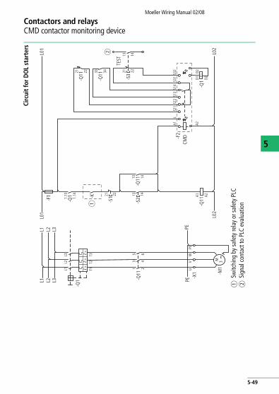
Circ
uit f
or D
OL
star
ters
aSw
itchi
ng b
y sa
fety
rela
y or
safe
ty P
LCb
Sign
al c
onta
ct to
PLC
eva
luat
ion
I >I >
I >
U <
M 3˜
-Q1
-Q1 -K
-S1-F1
-Q11
-X1 -M
1L1L2
L31.
13 21 22
1.14
-Q1113 14
-Q11
33 34
-Q11
21 22
-F2
CMD
-Q1D1 D2
D2
A1 A2
LS2
1S2
2S1
3S1
4S3
1S3
2
-Q11
A1 A2
T1 13
5
24
6
T2T3
L1L0
1L0
1
L02
L02
L2 PEU
VW
PEPE
L3
L1 L2 L3
-S2
13 14
-S3
21 22
13 14
a
b
TEST
5-49
Contactors and relaysCMD contactor monitoring device
Moeller Wiring Manual 02/08
5
Circ
uit f
or re
vers
ing
star
ters
aSw
itchi
ng b
y sa
fety
rela
y or
safe
ty P
LCb
Sign
al c
onta
ct to
PLC
eva
luat
ion
L1 L2 L3
L1 L2 L3
-Q1
-Q1 -K
-S1-F
1
-Q11
-X1 -M
1
-Q12
-Q11
-Q12
-Q11
-Q11
-Q12
-Q11
-F2
CMD
-Q12
-Q1
-Q11
L01
L01
L02
L02
PEPE
-F3
CMD
-S2
-S3
-S4
TEST
-Q12
-Q12
I >I >I >
U <
M 3˜
L1L2
L31.
13 21 22
1.14
13 1413 14 21 22
13 14
43 4421 22
31 32
31 32 A1 A2
D1 D2
D2D1
D2
A1A1
A2
LL
S21
S22
S13
S14
S31
S32
A1 A2
T1 13
5
24
6
13
5
24
6
T2T3
UV
WPE
A2
13 14 21 22
21 22
13 14
a
b
43 4421 22
S21
S22
S13
S14
S31
S32
5-50

NotesMoeller Wiring Manual 02/08
5
5-51

NotesMoeller Wiring Manual 02/08
5
5-52