Embed Size (px)
Citation preview

For more information, contact CULTEC at (203) 775-4416 or visit www.cultec.com.
© CULTEC, Inc., May 2014 CULTEC Stormwater Installation Instructions CULG012 05-14
1
Installation Instructions for CULTEC Stormwater Management SystemsContactor® Models Field Drain™ C-4HD™, 100HD™Recharger® Models 150XLHD™, 280HD™, 330XLHD™, & V8HD™
Contactor® & Recharger® Stormwater Chambers The Chamber With The Stripe®

For more information, contact CULTEC at (203) 775-4416 or visit www.cultec.com.
© CULTEC, Inc., May 2014 CULTEC Stormwater Installation Instructions CULG012 05-14
2
Published byCULTEC, Inc.P.O. Box 280878 Federal RoadBrookfield, Connecticut 06804 USAwww.cultec.com
Copyright Notice © 2014 CULTEC, Inc. All rights reserved. Printed in the USA.This document and any accompanying CULTEC products are copyright-ed by CULTEC, Inc. Any reproduction and/or distribution without prior written consent from CULTEC, Inc. is strictly prohibited.
Disclaimers: The drawings, photographs and illustrations shown in this document are for illustrative purposes only and are not necessarily to scale. Actual designs may vary.
CULTEC reserves the right to make design and/or specification changes at any time without notice at CULTEC’s sole discretion.
CULTEC is not responsible for typographical errors.
Protected by one or more of the following patents:Protected by one or more of the following patents:U.S. Patents 6,129,482; 6,322,288; 6,854,925; 7,226,241; 7,806,627; 8,366,346; 8,425,148; and others; U.S. Designs D613819; D638,095; D668,318 and others; Canadian Patent 2,591,255 and others; Community Designs 1092191; 1745209; and others. CULTEC, the CULTEC logo, RECHARGER, CONTACTOR, HVLV, PAC, STORMFILTER, STORMGENIE and The Chamber with The Stripe are registered trademarks of CULTEC, Inc.Chamber of Choice, 902, HD, 100, 125, 150, 150XL, 180, 280, 330, 330XL, V8, 900, Field Drain Pan-el, C-1, C-2, C-3, C-4, EZ-24, Landscape Series are trademarks of CULTEC, Inc. All rights reserved.
Contact Information:For general information on our other products and services, please contact our offices within the United States at (800)428-5832, (203)775-4416 ext. 2002, or e-mail us at [email protected].
For technical support, please call (203)775-4416 ext. 2003 or e-mail [email protected].
These instructions are for single-layer traffic applications only. For multi-layer applications, contact CULTEC.All illustrations and photos shown herein are examples of typical situations. Be sure to follow the engineer’s drawings. Actual designs may vary.
Stormwater Installation Instructions
Doc ID: CULG012 05-14May 2014You are using version CULG012 05-14 of our CULTEC Stormwater Installation Instructions

For more information, contact CULTEC at (203) 775-4416 or visit www.cultec.com.
© CULTEC, Inc., May 2014 CULTEC Stormwater Installation Instructions CULG012 05-14
3
BEFORE YOU BEGIN
Required Materials and Equipment
• Proper geotechnical soil evaluation by a qualified engineer or soil scientist to determine suitability of structural installation
• OSHA compliance• CULTEC warning tape, or equivalent• Assurances from local utilities that no underground gas, electrical or other potentially dangerous
pipelines or conduits are already buried at the site• Acceptable 1– 2 inch (25 - 51 mm) washed, crushed stone as shown in Table 4, page 19. Cleanli-
ness of stone to be verified by engineer. • Acceptable fill material as shown in Table 5, page 20• CULTEC No. 410™ filter fabric or equivalent non-woven filter fabric (See Table 3, page 19 for de-
tailed specifications)• All CULTEC chambers and accessories as specified in the engineer’s plans including CULTEC No.
410™ Filter Fabric, CULTEC StormFilter® and CULTEC No. 20L™ Polyethylene Liner, where appli-cable. Check CULTEC chambers for damage prior to installation. Do not use damaged CULTEC chambers, contact your supplier immediately to report damage or packing-list discrepancies.
• Reciprocating saw or router• Stone bucket• Stone conveyor and/or tracked excavator• Transit or laser level measuring device• Compaction equipment with maximum gross vehicle weight of 12,000 lbs (5,440 kgs). Vibratory
rollers may only be used on the stone base prior to the installation of chambers.
Requirements for CULTEC Chamber System Installations
• Installing contractors are expected to comprehend and use the most current installation instruc-tions prior to beginning a system installation. If there is any question as to whether these are the most current instructions, contact CULTEC at (203) 775-4416 or visit www.cultec.com.
• Contact CULTEC at least thirty days prior to system installation to arrange for a pre-construction meeting.
• All CULTEC system designs must be certified by a registered professional engineer.• Use these installation instructions as a guideline only. Actual design may vary. Refer to approved
construction drawings for job-specific details. Be sure to follow the engineer’s drawings as your primary guide.
• System cover/backfill requirements will vary based on CULTEC chamber model. Please refer to Table 6 on page 20 and engineer’s drawings.
• Any discrepancies with the system sub-grade soil’s bearing capacity must be reported to the design engineer.
• Filter fabric must be used as specified in the engineer’s drawings.• CULTEC requires the contractor to refer to CULTEC’s Installation Instructions Tables 1 - 6 shown
on pages 18 - 20, concerning vehicular traffic. Responsibility for preventing vehicles that exceed CULTEC’s requirements from traveling across or parking over the chamber system lies solely with the contractor throughout the entire site construction process. The placement of warning tape, temporary fencing, and/or appropriately located signs is highly recommended. Imprinted warning tape is available from CULTEC. For Acceptable Vehicle Load information, refer to Tables 1 and 2 on page 18.
• Erosion and sediment-control measures must meet local codes and the design engineer’s specifi-cations throughout the entire site construction process.
• CULTEC systems must be designed and installed in accordance with CULTEC’s minimum require-ments. Failure to do so will void the limited warranty (See page 22-23).

For more information, contact CULTEC at (203) 775-4416 or visit www.cultec.com.
© CULTEC, Inc., May 2014 CULTEC Stormwater Installation Instructions CULG012 05-14
4
CULTEC Contactor® Series End Detail Information
Large RibEnd Detail
Small RibEnd Detail
Model RHD is a starter / stand alone unit with two full endwalls. They are used to start lines or can be used singu-larly. They may also be trimmed to into model type EHD.
Model RHD
Model EHD
Model EHD is a middle / end unit with one closed endwall and one open end. They are used to continue lines and also used to end a line.
for Contactor Model 100HDDirectional arrows located on the top of the chamber point towards the Small Rib End.
CULTEC Recharger® Series End Detail Information for Recharger Models 150XLHD, 280HD, and 330XLHD
Large RibEnd Detail
Small RibEnd Detail
Model RHD is a stand alone unit with two fully closed endwalls. They are used when a single unit is required. They may also be trimmed to into model types SHD, IHD, or EHD.
Model EHD is an end unit with one fully open end and one fully closed endwall. They are used to end a chamber run.
Model SHD is a starter unit with one closed endwall and one partially open endwall. They are used to start a chamber row.
Model IHD is an intermediate unit with one fully open end and one partially open endwall. They are used to continue the length of a line of chambers.
Model RHD
Model EHD
Model IHD
Model SHD
Directional arrows located on the top of the chamber point towards the Small Rib End.
CHAMBER TYPES

For more information, contact CULTEC at (203) 775-4416 or visit www.cultec.com.
© CULTEC, Inc., May 2014 CULTEC Stormwater Installation Instructions CULG012 05-14
5
CULTEC End Detail Information for Recharger® V8HD
Model RHD is a stand alone unit with two fully closed endwalls. They are used when a single unit is required. They may be also be trimmed to into model types SHD or EHD.
Model EHD is an end unit with one fully open end and one fully closed endwall. They are used to end a chamber run.
Model SHD is a starter unit with one closed endwall and one partially open endwall. They are used to start a chamber row.
Model IHD is an intermediate unit with one fully open end and one partially open endwall. They are used to continue the length of a line of chambers.
Model RHD
Model EHD
Model IHD
Model SHD
Large RibEnd Detail
Small RibEnd Detail
Directional arrows located on the top of the chamber point towards the Small Rib End.
CHAMBER TYPES
Shown L->R: Contactor 100HD, Recharger 150XLHD, Recharger 280HD, Recharger 330XLHD and Recharger V8HD.

For more information, contact CULTEC at (203) 775-4416 or visit www.cultec.com.
© CULTEC, Inc., May 2014 CULTEC Stormwater Installation Instructions CULG012 05-14
6
REQUIREMENTS
Site Preparation and Excavation • Excavate and level the area per engineer’s drawings. Refer to plan view and cross-section details
and excavate bed to accommodate chambers and manifold system. Be sure to allow for a mini-mum 12 inch (305 mm) stone border around the perimeter of the system and unforeseen over-ages in your excavation calculations.
• Remove any standing water and maintain positive drainage of the site throughout the installa-tion. Dewatering procedures must be used if necessary.
• Prepare the sub-grade soil for the chamber bed as specified by the engineer’s drawings.
• Place CULTEC No. 410™ non-woven filter fabric (or equivalent — see Table 3, page 19) on the excavated bed bottom and perimeter sidewalls as specified by the engineer’s drawings. Filter fabric is required on the sides and over the top of the system. It is also recommended on the system bottom. Overlap the filter fabric by at least 24 inches (610 mm) where the fabric edges meet.
• Disperse a level base of 1 to 2 inch (25 - 51 mm) diameter washed, crushed stone over the entire area of the bed bottom (see Table 4, page 19 for stone requirements). Refer to the engi-neer’s drawings for sub-grade soil preparation and required stone foundation thickness.
• Compact the stone base to achieve a flat, level surface. Vibratory rollers may only be used on the stone base prior to the installation of chambers. Use of vibratory rollers is strictly prohibited on all other backfill layers.
Chamber Preparation and InstallationCULTEC Contactor® and Recharger® chambers have the distinctive features of a fully formed end wall and over-lapping rib connection. CULTEC chamber ribs are dimensionally sized with an open large rib and a closed smaller rib to allow for an easy interlocking rib connection.
• Identify and group the different chamber types to ensure proper placement and usage as out-lined on pages 4 - 5.
• Place one Starter Unit (Model S for Recharger® series, Model R for Contactor® series) as designed for each row of units to be installed. Directional arrows point towards the small rib end of the chamber.
• If using the side portal internal manifold feature, trim the side portal(s) according to guidelines located on the sidewall of the chamber, as required - see page 14. Insert one end of the HVLV Feed Connector into the trimmed portal to create the internal manifold. Refer to Manifold Installation section on page 10.
• Place middle chamber (Model I for Recharger® series, Model E for Contactor® series) so the directional arrow located in the center of the unit points downstream towards the end of the line. Overlap the large open end rib over the small rib of the preceding cham-ber’s end wall, interlocking the chambers together - see page 7 - 8. When placing chambers take care to maintain center-to-center separation requirements, measuring from the base of the cham-ber.

For more information, contact CULTEC at (203) 775-4416 or visit www.cultec.com.
© CULTEC, Inc., May 2014 CULTEC Stormwater Installation Instructions CULG012 05-14
7
INTERLOCK PROCEDURE
Directional arrows located on the top of the chamber point towards the Small Rib End. The open end of the next chamber overlaps the small rib end of the preceding chamber.
CULTEC Contactor® Series Typical Installation Methodfor Contactor Model 100HD
Interlock Model RHD to EHD using the patented overlapping rib connection.
• Start each row with a Model RHD.• Use Model EHD to continue the length of your row.• End your row by using a Model EHD.
Hidden End
Shown with side portal trimmed and optional CULTEC HVLV SFCx2 Feed Connector inserted.
Model RHD
Model EHD
Model EHD
Model EHD
• To ease backfilling requirements, only install as many middle chambers as the stone-laying bucket or conveyor can reach.
• Place stone as outlined on page 16 taking care not to drop stone over the last rib to be overlapped.
• Continue chamber and stone placement using middle cham-bers (Model I for Recharger® series, Model E for Contactor® series) to extend the length of the row.
• Model E chamber is used to end the line.
• Prior to the placement of the next line of chambers, the level and alignment of the chamber units shall be checked and cor-rected, where needed.

For more information, contact CULTEC at (203) 775-4416 or visit www.cultec.com.
© CULTEC, Inc., May 2014 CULTEC Stormwater Installation Instructions CULG012 05-14
8
CULTEC Typical Installation Method for Recharger® V8HD
Interlock Model SHD to IHD using the patented overlapping rib connection. Finish the line with Model EHD.
• Start each line with a Model SHD.• Use Model IHD to continue the length of your line.• End your line by using a Model EHD.
Hidden End
Shown with side portal trimmed and optional CULTEC HVLV FC-24 Feed Connector inserted.Model SHD
Model IHD
Model EHDModel IHDHidden End
Hidden End
Shown with side portal trimmed and optional
CULTEC HVLV F-110x4 Feed Connector inserted.
INTERLOCK PROCEDURE
CULTEC Recharger® Series Typical Installation Methodfor Recharger Models 150XLHD, 280HD, and 330XLHDInterlock Model SHD to IHD using the patented overlapping rib connection. Finish the row with Model EHD.
• Start each row with a Model SHD.• Use Model IHD to continue the length of your row.• End your row by using a Model EHD.
Hidden End
Shown with side portal trimmed and optional CULTEC HVLV Feed Connector inserted.
Model SHD
Model IHD
Model EHDModel IHD
Hidden End

For more information, contact CULTEC at (203) 775-4416 or visit www.cultec.com.
© CULTEC, Inc., May 2014 CULTEC Stormwater Installation Instructions CULG012 05-14
9
SPECIFICATIONS
Size (LxWxH)
Installed Length
Length Adjust-ment
Max. Inlet in Endwall
Max. O.D. in Side Portal
Compatible Feed
Connector
Contactor® Field Drain C-4HD
8.5’ x 48” x 8.5” 8’ 0.5’ 4.5”n/a n/a
2.59 m x 1219 mm x 216 mm 2.44 m 0.15 m 114 mm
Contactor® 100HD8’ x 36” x 12.5” 7.5’ 0.5’ 10” 6.9”
HVLV® SFCx2 Feed Connector
2.44 m x 914 mm x 318 mm 2.29 m 0.15 m 250 mm 175 mm
Recharger® 150XLHD11’ x 33” x 18.5” 10.25’ 0.75’ 12” 10.25”
HVLV® FC-24 Feed Connector
3.13 m x 838 mm x 470 mm 2.87 m 0.28 m 300 mm 260 mm
Recharger® 280HD8’ x 47” x 26.5” 7’ 1’ 18” 12.25”
HVLV® FC-24 Feed Connector
2.44 m x 1194 mm x 673 mm 2.13 m 0.30 m 450 mm 311 mm
Recharger® 330XLHD8.5’ x 52” x 30.5” 7’ 1.50’ 24” 11.75”
HVLV® FC-24 Feed Connector
2.59 m x 1321 mm x 775 mm 2.13 m 0.46 m 600 mm 298 mm
Recharger® V8HD8’ x 60” x 32” 7.5’ -5.83’ 24” V8SHD or V8EHD 15.3”
V8IHD 12.25” HVLV® F-110x4 Feed Connector
2.44 m x 1524 mm x 813 mm 2.29 m -1.78 m 600 mm V8SHD or V8EHD 387 mmV8IHD 311 mm
Recharger V8HD information is based on V8IHD Intermediate section.CULTEC Heavy Duty (HD) chambers must be used for any traffic applications. CULTEC Heavy Duty chambers have a colored stripe permanently affixed along the full length of the chamber. Chambers that do not have this stripe must not be used for traffic applications.All dimensions are nominal. Actual dimensions may vary on-site due to shipping and temperature.
CULTEC Chamber Specification Information
Model Size (LxWxH) Compatible Models Installed Length
(exposed)HVLV® SFCx2 Feed Connector
19.7” x 12” x 7.6”500 mm x 305 mm x 194 mm Contactor® 100HD For Contactor 100HD: 4” (102 mm) typ.
HVLV® FC-24 Feed Connector
12” x 16” x 24.2”305 mm x 406 mm x 614 mm
Recharger® 150XLHDRecharger® 280HD, Recharger® 330XLHD, Recharger® V8IHD Intermediate,
For Recharger 150XLHD: 6” (152 mm) typ.
For Recharger 280HD: 5” (127 mm) typ.
For Recharger 330XLHD: 6” (152 mm) typ.
For Recharger V8IHD: 6” (152 mm) typ.
HVLV® F-110x4 Feed Connector
39” x 27.5” x 18”991 mm x 699 mm x 457 mm
Recharger® V8RHD Stand Alone, Recharger® V8SHD Starter, Recharger® V8EHD End Not for Recharger® V8IHD Intermediate.
For Recharger V8HD: 6” (152 mm) typ.
CULTEC HVLV Feed Connector Specification Information
Shown L-->R: HVLV SFCx2 Feed Connector, HVLV FC-24 Feed Connector, HVLV F-110x4 Feed Connector
For more information, contact CULTEC at (203) 775-4416 or visit www.cultec.com.
© CULTEC, Inc., May 2014 CULTEC Stormwater Installation Instructions CULG012 05-14
10
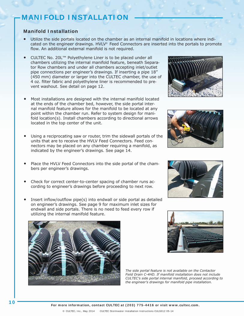
MANIFOLD INSTALLATION
The side portal feature is not available on the Contactor Field Drain C-4HD. If manifold installation does not include CULTEC’s side portal internal manifold, proceed according to the engineer’s drawings for manifold pipe installation.
Manifold Installation• Utilize the side portals located on the chamber as an internal manifold in locations where indi-
cated on the engineer drawings. HVLV® Feed Connectors are inserted into the portals to promote flow. An additional external manifold is not required.
• CULTEC No. 20L™ Polyethylene Liner is to be placed under all chambers utilizing the internal manifold feature, beneath Separa-tor Row chambers and under all chambers accepting inlet/outlet pipe connections per engineer’s drawings. If inserting a pipe 18” (450 mm) diameter or larger into the CULTEC chamber, the use of 4 oz. filter fabric and polyethylene liner is recommended to pre-vent washout. See detail on page 12.
• Most installations are designed with the internal manifold located at the ends of the chamber bed, however, the side portal inter-nal manifold feature allows for the manifold to be located at any point within the chamber run. Refer to system design for mani-fold location(s). Install chambers according to directional arrows located in the top center of the unit.
• Using a reciprocating saw or router, trim the sidewall portals of the units that are to receive the HVLV Feed Connectors. Feed con-nectors may be placed on any chamber requiring a manifold, as indicated by the engineer’s drawings. See page 14.
• Place the HVLV Feed Connectors into the side portal of the cham-bers per engineer’s drawings.
• Check for correct center-to-center spacing of chamber runs ac-cording to engineer’s drawings before proceeding to next row.
• Insert inflow/outflow pipe(s) into endwall or side portal as detailed on engineer’s drawings. See page 9 for maximum inlet sizes for endwall and side portals. There is no need to feed every row if utilizing the internal manifold feature.

For more information, contact CULTEC at (203) 775-4416 or visit www.cultec.com.
© CULTEC, Inc., May 2014 CULTEC Stormwater Installation Instructions CULG012 05-14
11
Directional arrows located on the top of the chamber point towards the Small Rib End.
PIPING INFORMATION
How to Trim CULTEC Chamber to Accommodate Pipe on Endwall
When using a conventional pipe manifold or inlet / outlet pipes, the contractor is required to trim the CULTEC Chamber on site.
Here are some quick steps to ensure a successful outcome:
• Lay out chambers according to engineered plans.
• Directional arrows located at the top of the chamber point towards the small rib end.
• Line up the pipe on the chamber endwall to the designated pipe elevation as detailed on the engineer’s drawing.
• Using a grease pen, outline the pipe on the end-wall of the CULTEC chamber.
• Drill a hole on the chamber endwall large enough to accommodate a saw bit.
• Following the grease pen outline, use a recipro-cating saw to trim out the opening to accommo-date the pipe. Trimming should be within 1/4” (6 mm) tolerance of pipe O.D.
• Insert the pipe or fitting a minimum of 8” (203 mm) into the chamber. This is not required to be a watertight connection.
• Backfill as noted in the installation instructions and engineering details.
Fig. 1
Trimming may only be performed on fully closed endwalls (indicated by Number 1 in Fig. 1) or side portal areas (See green circles in Fig. 1 for side portal locations). Pipe may not be inserted into the sidewall of the chamber unless it is within the side portal trim lines See page 14 for more informa-tion on trimming side portals.
1
Large RibEnd Detail
Small RibEnd Detail
Model E End Model
Model R Stand Alone Model
Model S Starter Model
1
1
1

For more information, contact CULTEC at (203) 775-4416 or visit www.cultec.com.
© CULTEC, Inc., May 2014 CULTEC Stormwater Installation Instructions CULG012 05-14
12
See Fig. 1
Description Contactor 100HD
Recharger 150XLHD
Recharger 280HD
Recharger 330XLHD
Recharger V8HD
A Min. depth of stone base 6”152 mm
6”152 mm
6”152 mm
6”152 mm
6”152 mm
B Chamber Height 12.5”318 mm
18.5”470 mm
26.5”673 mm
30.5”775 mm
32”813 mm
CMin. depth of stone required above units for traffic applica-tions
6”152 mm
6”152 mm
6”152 mm
6”152 mm
6”152 mm
D
Min. depth of required 95% compacted fill for paved ap-plications
8”203 mm
8”203 mm
8”203 mm
10”254 mm
12”305 mm
Min. depth required of 95% compacted fill for unpaved applications
10” 254 mm
10”254 mm
10”254 mm
12”305 mm
14”356 mm
E Max. depth of cover allowed above crown of chamber
12’3.66 m
12’3.66 m
12’3.66 m
12’3.66 m
8’2.44 m
FMax. inlet/outlet pipe size into the end wall of the chamber
10”250 mm
12”300 mm
18”1
450 mm124”1
600 mm124”1
600 mm1
Typical Cross Section for Hi-Flow Pipes
1 For Recharger Models 280HD, 330XLHD and V8HD, 4 oz. non-woven filter fabric to be placed beneath all chambers accepting inlet piping connections greater than 18” (450 mm) diameter. Filter fabric to extend a minimum of 10’ (3.04 m) past liner and overlap a minimum of 1’ (0.305 m) beneath the polyethylene liner. (See Fig. 1).
CROSS SECTION DETAILS
Fig. 1

For more information, contact CULTEC at (203) 775-4416 or visit www.cultec.com.
© CULTEC, Inc., May 2014 CULTEC Stormwater Installation Instructions CULG012 05-14
13
INSPECTION PORT DETAILS
Inspection Port Detail for Paved Traffic Applicationsnot for Contactor C-4HD or Recharger V8HD
Inspection Port Detail for Paved Traffic Applicationsfor Recharger V8HD
Fig. 1 Fig. 2
See Fig. 2 See Fig. 1
The Recharger V8HD has an 8” (200 mm) diameter inspection port on Model V8SHD Starters, V8RHD Stand Alone and V8EHD End units. The Recharger V8IHD Intermediate unit has a 6” (150 mm) diameter inspection port opening.
See Fig. 1

For more information, contact CULTEC at (203) 775-4416 or visit www.cultec.com.
© CULTEC, Inc., May 2014 CULTEC Stormwater Installation Instructions CULG012 05-14
14
When using the side portal internal manifold feature, the contractor is required to trim the side por-tal of the CULTEC Chamber on site.
Model Compatible Feed Connector
Contactor 100HD HVLV SFCx2 Feed Connector
Recharger 150XLHD HVLV FC-24 Feed Connector
Recharger 280HD HVLV FC-24 Feed Connector
Recharger 330XLHD HVLV FC-24 Feed Connector
Recharger V8RHD, V8SHD, V8EHD HVLV F-110x4 Feed Connector
Recharger V8IHD HVLV FC-24 Feed Connector
OK
NO
side portal
Trimming may only be performed on the side portal area. Side entry in any other location is unacceptable.
Following the guides on the side portal, use a reciprocating saw to trim out the opening to accom-modate the HVLV Feed Connector.
Insert the HVLV Feed Connector into the chamber. This is not required to be a watertight connection.
Shown L-->R: Guidelines to follow for correct trim-ming for SFCx2, FC-24 and F-110x4 portals. Do not cut outside of the side portal area guides.
INTERNAL MANIFOLD
How to Trim Side Portal to Accommodate HVLV Feed Connector for Internal Manifold
For more information, contact CULTEC at (203) 775-4416 or visit www.cultec.com.
© CULTEC, Inc., May 2014 CULTEC Stormwater Installation Instructions CULG012 05-14
15
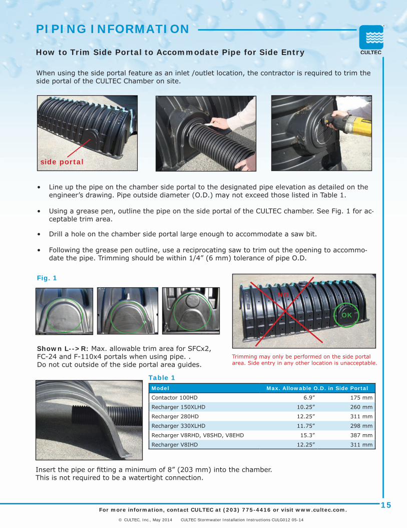
When using the side portal feature as an inlet /outlet location, the contractor is required to trim the side portal of the CULTEC Chamber on site.
Model Max. Allowable O.D. in Side Portal
Contactor 100HD 6.9” 175 mm
Recharger 150XLHD 10.25” 260 mm
Recharger 280HD 12.25” 311 mm
Recharger 330XLHD 11.75” 298 mm
Recharger V8RHD, V8SHD, V8EHD 15.3” 387 mm
Recharger V8IHD 12.25” 311 mm
Shown L-->R: Max. allowable trim area for SFCx2, FC-24 and F-110x4 portals when using pipe. . Do not cut outside of the side portal area guides.
OK
NO
Trimming may only be performed on the side portal area. Side entry in any other location is unacceptable.
Fig. 1
Insert the pipe or fitting a minimum of 8” (203 mm) into the chamber. This is not required to be a watertight connection.
• Line up the pipe on the chamber side portal to the designated pipe elevation as detailed on the engineer’s drawing. Pipe outside diameter (O.D.) may not exceed those listed in Table 1.
• Using a grease pen, outline the pipe on the side portal of the CULTEC chamber. See Fig. 1 for ac-ceptable trim area.
• Drill a hole on the chamber side portal large enough to accommodate a saw bit.
• Following the grease pen outline, use a reciprocating saw to trim out the opening to accommo-date the pipe. Trimming should be within 1/4” (6 mm) tolerance of pipe O.D.
side portal
How to Trim Side Portal to Accommodate Pipe for Side Entry
PIPING INFORMATION
Table 1

For more information, contact CULTEC at (203) 775-4416 or visit www.cultec.com.
© CULTEC, Inc., May 2014 CULTEC Stormwater Installation Instructions CULG012 05-14
16
BACKFILL PROCEDURE
Embedment Stone Backfill
Backfill using washed, crushed stone as specified in Table 4, page 19 and Table 5, page 20. To maintain row separation distance and pre-vent chamber displacement, slowly distribute stone on top of chamber crown so that stone builds between chamber rows as required. Stone column differential should not exceed 12” (300 mm) between adjacent chamber rows or between chamber rows and perimeter.
CULTEC recommends two methods of stone placement: excavator or stone conveyor boom.
Excavator-Placed StoneTypically the most common method, excavator-placed stone is limited by the reach of the arm. To accommodate this issue with larger beds, it is common to prepare a bed by joining just a few chamber units at a time, then placing the stone and fabric before installing the next few units.
The excavator is usually operated within the excavation area. The excavator may work at grade level over recently placed chambers, provided coverage between the chambers and the excavator tracks meets the minimum requirements as shown in Table 2, page 18 and Table 6, page 20.
Telescoping Conveyor Boom PlacementWith booms as much as 120-140 feet (36.6 - 42.7 meters) long, telescoping aggregate conveyors can greatly aid the process of stone placement.
With both stone-placement methods, ladling the stone carefully over the chambers’ centers will secure them in place. Evenly distributing the stones will help prevent chamber movement and maintain row separation.
Once secured, stone may be placed to surround the chambers and fill the perimeter areas. System cover/backfill requirements will vary based on CULTEC chamber model. Refer to Table 6 on page 20 and engineer’s drawings.
Do not allow equipment to drive over the chambers unless the mini-mum cover as shown in Table 6, page 20 is in place. Use a warning tape (available from CULTEC) to restrict access.
Repeat steps until all of the last chamber units are in place. Be certain to use the Model E to end the line of chambers in place as specified by the drawings.
If a manifold system is designed on the back end of the chamber bed, follow manifold installation instructions as described previously.

For more information, contact CULTEC at (203) 775-4416 or visit www.cultec.com.
© CULTEC, Inc., May 2014 CULTEC Stormwater Installation Instructions CULG012 05-14
17
BACKFILL PROCEDURE
Top Fabric Layer Placement & System Backfill Process
• Backfill over the chamber bed (See 4 in Fig. 1 on page 21) in 6-inch (152 mm) maximum lifts until the specified grade is achieved. CULTEC’s cover requirements vary by model. See Table 3, page 19 for minimum and maximum coverage. For pavement sub-base or special fill require-ments, see engineer’s drawings.
• Backfill height differential should never exceed 24 inches (610 mm) with adjacent chambers. Minimum depth of cover of properly compacted material must be met before allowing vehicles to drive over the bed. Avoid using large rocks and/or organic matter as backfill material. See Table 5, page 20 for acceptable cover materials, or contact the design engineer for approved fill types.
• Place the stone over the entire bed area as described in previous section (See 2 in Fig. 1 on page 21).
• Cover the entire installation area with CULTEC No. 410 non-woven filter fabric, starting from the perimeter and laying it atop the stone. The filter fabric must overlap at least 24 inches (610 mm) at the edges.
• Fill the first 12 inches (305 mm) with enough material (See 3 in Figure 1 on page 21) to meet the requirements as shown in Table 5, page 20. Backfill over the top of the filter fabric (See 3 in Fig. 1 on page 21) in lifts that do not exceed 6 inches (152 mm), and dis-perse the fill with a vehicle that meets the maximum wheel loads or ground pressure limits as specified on specified in Tables 1 & 2 on page 18.
• Compact each lift of backfill as specified in the engineer’s draw-ings. CULTEC specifies compacting to a minimum of 95% of the standard proctor density using compaction equipment with a gross vehicle weight of less than of 12,000 lbs (5,400 kg). The use of vibratory equipment is strictly prohibited and will void any warranties.

For more information, contact CULTEC at (203) 775-4416 or visit www.cultec.com.
© CULTEC, Inc., May 2014 CULTEC Stormwater Installation Instructions CULG012 05-14
18
Table 1: Maximum allowable axle loads for wheeled vehicles at various cover depths
ACCEPTABLE VEHICLE LOADS
Table 2: Maximum allowable ground pressures for various vehicle track widths and fill depths
Any load which travels over the system that exceeds the maximum load allowed is strictly prohibited and will void the warranty.All depths listed above are based on compacted fill and include min. 6” (152 mm) of stone above the crown of the unit as listed as 3 of Fig. 1, page 21.
2 Ground pressure is vehicle operating weight divided by total truck contact area for both tracks. Turning should be kept to a minimum.
Fill Depth Over Chamber Max. Axle Load
inches mm lbs kN
All Models 6 152 8,000 35.6
All Models 9 305 16,000 71.2
Contactor® Field Drain C-4HD 14” with pavement 18” without pavement
356 mm with pavement457 mm without pavement 40,000 177.9
Contactor® 100HDRecharger® 150XLHDRecharger® 280HD
14” with pavement16” without pavement
356 mm with pavement406 mm without pavement 40,000 177.9
Recharger® 330XLHD 16” with pavement18” without pavement
406 mm with pavement457 mm without pavement 40,000 177.9
Recharger® V8HD 18” with pavement20” without pavement
457 mm with pavement508 mm without pavement 40,000 177.9
Fill Depth Over Chamber Track Width Max. Ground Pressure2
inches mm inches mm PSF kPa
6 152
1218243036
305457610762914
1070900800760720
5143383634
12 305
1218243036
305457610762914
154011901010910840
7457484340
18 457
1218243036
305457610762914
2010148012201060950
9671585145
The use of wheeled equipment is strictly prohibited.

For more information, contact CULTEC at (203) 775-4416 or visit www.cultec.com.
© CULTEC, Inc., May 2014 CULTEC Stormwater Installation Instructions CULG012 05-14
19
Substitutions must meet or exceed these minimums.Filter fabric placement is mandatory over top and sides of system. Coverage of system bottom is recommended, however, follow engineer’s design preference.
Properties Test Method Test Results
Appearance Black
Grab Tensile D 463290 lbs
400 N
Elongation D 4632 50%
Trapezoid Tear D 453335 lbs
155 N
Puncture D 483355 lbs
245 N
Mullen Burst D 3786175 psi
1205 kPa
AOS D 475170 U.S. sieve
.21 mm
Permittivity D 4491 2.0 sec-1
Permeability D 4491 .2 cm/sec
Water Flow D 4491145 gal/min/sf
5908 l/min/sq.mt
UV Stability D 4355 70%
ACCEPTABLE MATERIALS
Table 3: CULTEC No. 410™ Non-Woven Filter Fabric Specification Information
Table 4: Criteria for acceptable 1 - 2 inch (25 - 51 mm) washed, crushed, angular stone
Washed Crushed Stone Description Criteria
Acceptable
Angular Stones have sharp edges and relatively plane sides with unpolished surfaces
Subangular Stones are similar to angular description but may have slightly rounded edges
UnacceptableSubrounded Stones have nearly plane sides but have well-rounded cor-
ners and edges
Rounded Stones have smoothly curved sides and no edges
See 1 and 2 of Table 5 for additional stone requirements.

For more information, contact CULTEC at (203) 775-4416 or visit www.cultec.com.
© CULTEC, Inc., May 2014 CULTEC Stormwater Installation Instructions CULG012 05-14
20
Table 6: Minimum and Maximum Fill and Separation Requirements for Traffic Installations(See Fig. 1 on page 21)
A B C
Model
Minimum Fill Requirements
Maximum Fill Requirements
Center-to-Center Separation Requirement
For Paved inches
For Pavedmm
For Unpavedinches
For Unpaved
mmfeet m inches mm
Contactor® Field Drain C-4HD 14 356 16 406 12 3.66 48 1219
Contactor® 100HD 14 356 16 406 12 3.66 40 1016
Recharger® 150XLHD 14 356 16 406 12 3.66 39 991
Recharger® 280HD 14 356 16 406 12 3.66 52 1321
Recharger® 330XLHD 16 406 18 457 12 3.66 58 1473
Recharger® V8HD 18 457 20 508 8 2.44 66 1676
Refer to Table 5 and Fig. 1 on page 21 and Table 4 on page 19 for acceptable fill requirements.Table refers to Heavy Duty version only, requirements differ for Standard Duty version. When fill requirements will exceed Maximum Fill Requirements listed above, contact CULTEC at 203-775-4416.All depths listed above are based on compacted fill and include the required stone above the crown of the unit.
ACCEPTABLE FILL MATERIALSTable 5: Acceptable Fill Materials
Material Location DescriptionAASHTO
M43Classification
AASHTOM145
Classification
Compaction/ Density
Requirement
1Foundation Stone below chambers per engi-neer’s drawing6” (152 mm) min. re-quired for most models.
Washed, crushed stone with the majority of par-ticles between 1” - 2” (25 - 51 mm)
4, 5, 56, 57, 467 Per engineer’s drawings
Plate compact or roll to achieve a 95% Standard Proctor density
2Embedment Stone surrounding chambers and to a min. 6” (152 mm) elevation above chamber crown for most models.
Washed, crushed stone with the majority of par-ticles between 1” - 2” (25 - 51 mm)
4, 5, 56, 57, 467Per engineer’s drawings
No compaction required
3
Fill Material for Layer 3 starts from top of embed-ment stone (Layer 2) to minimum required depth above top of chamber.Refer to Table 6 page 20 for proper minimum fill requirements.
Granular well-graded soil/aggregate mixtures, <35% fines
4, 5, 6, 7, 8, 9, 10, 56, 57, 67, 68, 78, 89, 467
Group A-1Group A-2Group A-3
Compact in 6” (152 mm) lifts to a minimum 95% Standard Proctor den-sity. Roller gross vehicle weight not to exceed 12,000 lbs. (53 kN) Dynamic force not to ex-ceed 20,000 lbs. (89 kN)
4
Fill Material for Layer 4 starts from the top of Layer 3 to the bottom of pavement or unpaved fin-ished grade above. Refer to Table 6 page 20 for proper chamber model minimum fill requirements.
Any soil/rock materials, native soils or per engi-neer’s plans. Check plans for pavement subgrade requirements.
Per engineer’s drawings
Per engineer’s drawings
Prepare per engineer’s drawing. Paved installations may have strict material and preparation requirements
The listed AASHTO classifications are for gradations. The stone must be washed, crushed and angular. See Table 6, page 20.For example, the stone must be specified as washed, crushed No. 4 stone. Fill materials shall be free of debris, trash, frozen lumps and other deleterious matter.
STONE BORDER WIDTH 12” (300 mm) MIN.

For more information, contact CULTEC at (203) 775-4416 or visit www.cultec.com.
© CULTEC, Inc., May 2014 CULTEC Stormwater Installation Instructions CULG012 05-14
21
ACCEPTABLE FILL MATERIALSFig. 1. Fill Material Locations – refer to Tables 4, 5, and 6.
CHAMBER WIDTH
CENTER-TO-CENTERC
SEE TABLE 5 FOR MIN.
CHAMBER HEIGHT
SEE TABLE 5FOR MIN.
AB
CULTEC HEAVY DUTY CHAMBER CULTEC HVLV FEED CONNECTOR (PER DESIGN)
CULTEC NO. 410 FILTER FABRIC (OR EQUIVALENT) AROUND STONE IN LAYERS 1 & 2.TOP AND SIDES ARE MANDATORY,BOTTOM PER ENGINEER’S DESIGN PREFERENCE
CULTEC NO. 20L POLYETHYLENE LINER TO BE PLACED BENEATH CHAMBERS UTILIZING INTERNAL MANIFOLD FEATURE
1
2
3
4
STONE BORDER WIDTH 12” (300 mm) MIN.

For more information, contact CULTEC at (203) 775-4416 or visit www.cultec.com.
© CULTEC, Inc., May 2014 CULTEC Stormwater Installation Instructions CULG012 05-14
22
CULTEC, Inc. finished products, when properly installed, registered with Cultec, Inc., and operated under normal conditions of use, are covered under Cultec Inc.’s Limited Warranty to be free from defects in material and workmanship for a period of one (1) year from the date of manufacture. In order to obtain Cultec’s Limited Warranty, the product warranty registration card must be completed and returned to Cultec, Inc., having been postmarked within thirty (30) days of installation. Failure to return the warranty registration card to Cultec, Inc. shall void the Limited Warranty. This Limited Warranty shall be void if the finished product is not installed within forty-five (45) days of the date of purchase from Cultec, Inc. In order to obtain performance under this Limited Warranty, Cultec, Inc. must be provided with written notice of any defect promptly (in no case later than ten (10) business days after initial discovery AND prior to the end of the Limited Warranty period), with such notice sent to 878 Federal Road, PO Box 280, Brookfield, CT 06804-0280. The original purchase receipt for the product must be included with documentation supporting any claim under the terms of this Limited Warranty. Failure to promptly submit notice of defect, a receipt and completed limited warranty certificate will void the Limited Warranty. Cultec, Inc. shall not be responsible for any freight charges incurred in connection with this Limited Warranty. A fee may be incurred when Cultec, Inc. (in its sole discretion) deems it necessary for a Cultec, Inc. representative to visit a product installation site.
This Limited Warranty extends only to Cultec, Inc. products when the products are installed in ‘single level’, provided that such products do not, in the collective, amount to more than 12,000 cubic feet (339.84 cubic meters) of water volume storage capacity. This Limited Warranty shall be void where products are installed in ‘multi-layer’ or ‘multi-tier’ systems, as well as wherein collective system volume exceeds 12,000 cubic feet (339.84 cubic meters) of water volume storage capac-ity. Notwithstanding the foregoing, Cultec, Inc., in its sole discretion, may extend certain Limited Warranty terms upon ‘double-layer’ or ‘double-tier’ product installations, as well as ‘single level’ product installations wherein collective system volume exceeds 12,000 cubic feet (339.84 cubic meters) of water volume storage capacity, provided that (i) the buyer has contacted Cultec, Inc. prior to installation and has advised of the proposed installation design; (ii) all product warranty registration information has been provided prior to product installation; (iii) a pre-construction/pre-installation meeting has been held with representatives of Cultec, Inc.; and (iv) Cultec, Inc. has provided written confirmation of its intent to honor any Limited Warranty terms with respect to the specific installation. Under no circumstances shall any decision by Cultec, Inc. to honor such terms be relied upon by any party in any subsequent product purchase or installation.
This Limited Warranty does not apply to installation piping and/or other parts not supplied by Cultec, Inc. Cultec, Inc.’s lim-ited warranties also do not extend to any goods or parts which have been damaged prior to installation, subjected to mis-use, damaged by lack of maintenance, improper installation, neglect, damaged by accident, or damaged by being crushed by heavy equipment weighing in excess of the rated load carrying capacity of the product. This Limited Warranty also does not apply to shipping or in-transit damage.
THIS LIMITED WARRANTY DOES NOT APPLY TO CULTEC, INC. PRODUCTS THAT HAVE NOT BEEN INSTALLED ACCORDING TO CULTEC WRITTEN INSTALLATION INSTRUCTIONS. ANY PRODUCT DAMAGE OR FAILURE RESULTING FROM IMPROPER OR NEGLIGENT INSTALLATION IS SPECIFICALLY EXCLUDED FROM THIS WARRANTY AND SHALL REMAIN THE BUYER’S RESPONSIBILITY.
THIS WARRANTY IS LIMITED TO THE BUYER AND IS NOT TRANSFERABLE. THIS EXPRESS LIMITED WARRANTY EXCLUDES ALL OTHER WARRANTIES OR REPRESENTATIONS, EXPRESSED, IMPLIED, OR STATUTORY, BY ANY LITERATURE, DATA, OR PERSON. CULTEC, INC. EXPRESSLY DISCLAIMS ANY WARRANTY OF MERCHANTABILITY OR FITNESS FOR A PARTICULAR USE OR PURPOSE WITH RESPECT TO THE GOODS SOLD. THERE ARE NO WARRANTIES WHICH EXTEND BEYOND THE DE-SCRIPTIONS SET FORTH IN THIS LIMITED WARRANTY, NOTWITHSTANDING ANY KNOWLEDGE OF CULTEC, INC. REGARD-ING THE USE OR USES INTENDED TO BE MADE OF GOODS, PROPOSED CHANGES OR ADDITIONS TO GOODS, OR ANY ASSISTANCE OR SUGGESTIONS THAT MAY HAVE BEEN MADE BY CULTEC, INC. PERSONNEL. BUYER IS RESPONSIBLE FOR DETERMINING THE SUITABILITY OF CULTEC, INC. PRODUCTS FOR BUYER’S USE OR RESALE, OR FOR INCORPORATING THEM INTO OBJECTS OR APPLICATIONS WHICH BUYER DESIGNS, ASSEMBLES, CONSTRUCTS OR MANUFACTURES.
CULTEC, INC. WILL NOT BE RESPONSIBLE OR LIABLE FOR INDIRECT OR CONSEQUENTIAL DAMAGES OF ANY KIND, HOW-EVER ARISING, INCLUDING BUT NOT LIMITED TO THOSE FOR USE OF ANY PRODUCTS, LOSS OF TIME, INCONVENIENCE, LOST PROFIT, LABOR CHARGES, OR OTHER INCIDENTAL OR CONSEQUENTIAL DAMAGES WITH RESPECT TO PERSONS, BUSINESS, OR PROPERTY, WHETHER AS A RESULT OF BREACH OF WARRANTY, NEGLIGENCE OR OTHERWISE. NOTWITH-STANDING ANY OTHER PROVISION OF THIS LIMITED WARRANTY, BUYER’S REMEDY AGAINST CULTEC, INC. FOR GOODS SUPPLIED OR FOR NON-DELIVERED GOODS OR FAILURE TO FURNISH GOODS, WHETHER OR NOT BASED ON NEGLIGENCE, STRICT LIABILITY OR BREACH OF EXPRESS OR IMPLIED WARRANTY, IS LIMITED SOLELY, AT CULTEC, INC.’S OPTION, TO REPLACEMENT OF OR CURE OF SUCH NONCONFORMING OR NON-DELIVERED GOODS OR RETURN OF THE PURCHASE PRICE FOR SUCH GOODS AND IN NO EVENT SHALL EXCEED THE PRICE OR CHARGE FOR SUCH GOODS. CULTEC, INC.’S MAXIMUM LIABILITY UNDER THIS EXCLUSIVE REMEDY SHALL NEVER EXCEED THE COST OF THE SUBJECT PRODUCT. CULTEC, INC. RESERVES THE RIGHT, AT ITS SOLE DISCRETION, TO REFUND THE PURCHASE PRICE IN LIEU OF REPAIR OR REPLACEMENT.
LIMITED 1-YEAR WARRANTY

For more information, contact CULTEC at (203) 775-4416 or visit www.cultec.com.
© CULTEC, Inc., May 2014 CULTEC Stormwater Installation Instructions CULG012 05-14
23
• Cultec, Inc.’s 1-Year Limited Warranty coverage applies only to new products purchased from an Authorized Cultec Dealer/Distributor and is based on the date of manufacture.
• If warranty service is required, every effort will be made to replace covered product with identical model. However, we reserve the right to make equal or better substitution as needed.
Disclaimer:THIS LIMITED WARRANTY DOES NOT APPLY TO INSTALLATION PIPING AND/OR OTHER PARTS NOT SUPPLIED BY CULTEC, INC. CULTEC, INC.’S LIMITED WARRANTIES ALSO DO NOT EXTEND TO ANY GOODS OR PARTS WHICH HAVE BEEN DAM-AGED PRIOR TO INSTALLATION, SUBJECTED TO MISUSE, DAMAGED BY LACK OF MAINTENANCE, IMPROPER INSTALLATION, NEGLECT, DAMAGED BY ACCOUNT, OR DAMAGED BY BEING CRUSHED BY HEAVY EQUIPMENT WEIGHING IN EXCESS OF THE RATED LOAD CARRYING CAPACITY OF THE PRODUCT. THIS LIMITED WARRANTY ALSO DOES NOT APPLY TO SHIPPING OR IN TRANSIT DAMAGE.
THIS LIMITED WARRANTY DOES NOT APPLY TO CULTEC, INC. PRODUCTS THAT HAVE NOT BEEN INSTALLED ACCORDING TO CULTEC WRITTEN INSTALLATION INSTRUCTIONS. ANY PRODUCT DAMAGE OR FAILURE RESULTING FROM IMPROPER OR NEGLIGENT INSTALLATION IS SPECIFICALLY EXCLUDED FROM THIS WARRANTY AND SHALL REMAIN THE BUYER’S RESPONSIBILITY.
THIS EXPRESS LIMITED WARRANTY EXCLUDES ALL OTHER WARRANTIES OR REPRESENTATIONS, EXPRESSED, IMPLIED, OR STATUTORY, BY ANY LITERATURE, DATA, OR PERSON. CULTEC, INC. EXPRESSLY DISCLAIMS ANY WARRANTY OF MER-CHANTABILITY OR FITNESS FOR A PARTICULAR USE OR PURPOSE WITH RESPECT TO THE GOODS SOLD. THERE ARE NO WARRANTIES WHICH EXTEND BEYOND THE DESCRIPTIONS SET FORTH IN THIS LIMITED WARRANTY, NOTWITHSTAND-ING ANY KNOWLEDGE OF CULTEC, INC. REGARDING THE USE OR USES INTENDED TO BE MADE OF GOODS, PROPOSED CHANGES OR ADDITIONS TO GOODS, OR ANY ASSISTANCE OR SUGGESTIONS THAT MAY HAVE BEEN MADE BY CULTEC, INC. PERSONNEL. CUSTOMER IS RESPONSIBLE FOR DETERMINING THE SUITABILITY OF CULTEC, INC. PRODUCTS FOR CUSTOMER’S USE OR RESALE, OR FOR INCORPORATING THEM INTO OBJECTS OR APPLICATIONS WHICH CUSTOMER DE-SIGNS, ASSEMBLES, CONSTRUCTS OR MANUFACTURES.
CULTEC, INC. WILL NOT BE RESPONSIBLE OR LIABLE FOR INDIRECT OR CONSEQUENTIAL DAMAGES OF ANY KIND, HOW-EVER ARISING, INCLUDING BUT NOT LIMITED TO THOSE FOR USE OF ANY PRODUCTS, LOSS OF TIME, INCONVENIENCE, LOST PROFIT, LABOR CHARGES, OR OTHER INCIDENTAL OR CONSEQUENTIAL DAMAGES WITH RESPECT TO PERSONS, BUSINESS, OR PROPERTY, WHETHER AS A RESULT OF BREACH OF WARRANTY, NEGLIGENCE OR OTHERWISE. NOTWITH-STANDING ANY OTHER PROVISION OF THIS LIMITED WARRANTY, BUYER’S REMEDY AGAINST CULTEC, INC. FOR GOODS SUPPLIED OR FOR NON-DELIVERED GOODS OR FAILURE TO FURNISH GOODS, WHETHER OR NOT BASED ON NEGLIGENCE, STRICT LIABILITY OR BREACH OF EXPRESS OR IMPLIED WARRANTY, IS LIMITED SOLELY, AT CULTEC, INC.’S OPTION, TO REPLACEMENT OF OR CURE OF SUCH NONCONFORMING OR NON-DELIVERED GOODS OR RETURN OF THE PURCHASE PRICE FOR SUCH GOODS AND IN NO EVENT SHALL EXCEED THE PRICE OR CHARGE FOR SUCH GOODS. CULTEC, INC.’S MAXIMUM LIABILITY UNDER THIS EXCLUSIVE REMEDY SHALL NEVER EXCEED THE COST OF THE SUBJECT PRODUCT. CULTEC, INC. RESERVES THE RIGHT, AT ITS SOLE DISCRETION, TO REFUND THE PURCHASE PRICE IN LIEU OF REPAIR OR REPLACEMENT.
Contact information for warranty assistance:Mail: CULTEC, Inc. • P.O. Box 280 • Brookfield, CT 06804-0280 USAFax: 203-775-5887 • E-mail: [email protected]
LIMITED 1-YEAR WARRANTY
CULG012 05-14
Chamber of Choice™
CULTEC, Inc.878 Federal Road • P.O. Box 280 • Brookfield, CT 06804 USA
Phone: 203-775-4416 • Toll Free: 1-800-4-CULTEC • Fax: 203-775-1462Web: www.cultec.com • E-mail: [email protected]