Embed Size (px)
Citation preview
Contacted mode-locking-dye cell
A. J. Cox, Gary W. Scott, and Larry D. Talley A. J. Cox is with University of Redlands, Physics Department, Redlands, California 92373; the other authors are with University of California, Riverside, Chemistry Department, Riverside, California 92521. Received 11 September 1978. 0003-6935/78/1201-3706$0.50/0. © 1978 Optical Society of America.
The mode-locked Nd+3:glass laser usually is realized by the introduction of a mode-locking dye (saturable absorber), such as Eastman 9860 solution in the laser cavity. The first mode-locked Nd+3:glass laser was passively mode-locked by using a relatively thick cell of mode-locking dye placed within the laser cavity.1 Following that report, a commonly used configuration was a 1-cm mode-locking dye cell placed at Brewster's angle in the cavity. However, subsequent studies showed the benefits of utilizing relatively thin cells (~50 µm) in optical contact with one of the mirror surfaces.2-4 These benefits include suppression of satellite pulses as well as generation of shorter laser pulses. Other flashlamp-pumped mode-locked lasers, such as ruby and dye lasers, also utilize a contacted dye cell.5
A contacted dye cell, which features a simple compact design for passive mode-locking, is described in this Letter. This cell is designed for use with an Nd+3:glass laser. It is constructed to contain an Eastman 9860 mode-locking dye in dichloroethane contacted with the 2-in. (5.08-cm) diam output mirror of the laser. The inner thickness of the cell is fixed at ~50 µm by Teflon spacers, and the outside dimensions of the cell are 3.49 cm thick by 7.62 cm in diameter. The cell is mounted in a conventional 3-in. (7.62-cm) mirror mount. Although the Nd+3:glass laser rod is only 1.27 cm in diameter, a 5.08-cm cell aperture was chosen so that in the event of damage to the optical components (e.g., a small burn spot),
3706 APPLIED OPTICS / Vol. 17, No. 23 / 1 December 1978
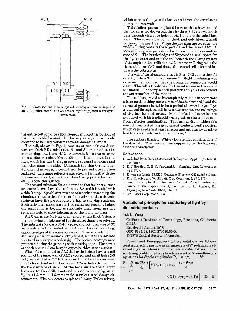
Fig. 1. Cross-sectional view of dye cell showing aluminum rings AL1 and AL2, substrates S1 and S2, the sealing O-rings, and the Swagelok
connectors.
the entire cell could be repositioned, and another portion of the mirror could be used. In this way a single mirror could continue to be used following several damaging events.
The cell, shown in Fig. 1, consists of two 5.08-cm diam, 0.95-cm thick BK7 substrates, SI and S2, mounted in aluminum rings, AL1 and AL2. Substrate S1 is coated on its inner surface to reflect 50% at 1064 nm. It is mounted in ring AL1, which has two O-ring grooves, one near its surface and the other along the side. (Although the side O-ring is redundant, it serves as a second seal to prevent dye solution leakage.) The inner reflective surface of S1 is flush with the flat surface of ALl, while the surface O-ring protrudes about 40 µm above this surface.
The second substrate S2 is mounted so that its inner surface protrudes 25 µm above the surface of AL2, and it is sealed with a side O-ring. Special care must be taken when machining the aluminum rings so that the rings fit snugly and the substrate surfaces have the proper relationship to the ring surfaces. Each individual substrate must be measured precisely before the machining is begun, as substrate dimensions are not generally held to close tolerances by the manufacturers.
All O-rings are 5.08-cm diam and 3.2-mm thick Viton, a material which is tolerant of the dichloroethane dye solvent. The substrate S2 was a 30-ft. wedge, and both surfaces of S2 were antireflection coated at 1064 nm. Before mounting, opposite edges of the inner surface of S2 were beveled off at 45° using a carborundum cutting wheel, while the substrate was held in a simple wooden jig. The optical coatings were protected during the grinding with masking tape. The bevels are each about 1.9 cm long on opposite sides of the surface.
When S2 is mounted in AL2 the beveled edges leave a small portion of the inner wall of AL2 exposed, and small holes (56 drill) were drilled at 25° to the normal into these two surfaces. The holes extend until they meet 0.32-cm holes drilled into the back surface of AL2. At the back surface these larger holes are further drilled out and tapped to accept 1/16-in. × 1/16-in. (1.5-mm × 1.5-mm) male stainless steel Swagelok connectors. The connectors couple to 18-gauge Teflon tubing,
which carries the dye solution to and from the circulating pump and reservoir.
Thin Teflon spacers are placed between the substrates, and the two rings are drawn together by three 8-32 screws, which pass through clearance holes in AL1 and are threaded into AL2. The spacers are 50 µm thick and only block a small portion of the aperture. When the two rings are together, the middle O-ring contacts the edge of S1 and the face of AL2. A second O-ring also provides a backup seal on the circumference of S1. The beveled edges of S2 provide a small space for the dye to enter and exit the cell beneath the O-ring by way of the angled holes drilled in AL2. Another O-ring seals the circumference of S2, and thus a thin closed cell is formed between the substrates.
The o.d. of the aluminum rings is 3 in. (7.62 cm) so they fit directly into a 3-in. mirror mount.6 Slight machining was done on the mount so that the Swagelok connectors would clear. The cell is firmly held by two set screws in the side of the mount. The compact cell protrudes only 2.41 cm beyond the outer surface of the mount.
The cell has proved to be completely reliable in operation: a laser mode-locking success rate of 80% is obtained,5 and the mirror alignment is stable for a period of several days. Dye is pumped through the cell between laser shots, and no leakage of dye has been observed. Mode-locked pulse trains are produced with high reliability using this contacted dye cell-front reflector combination. The laser cavity in which this dye cell was tested is a generalized confocal configuration, which uses a spherical rear reflector and intracavity negative lens to compensate for thermal lensing.4
The authors thank E. Whitey Dorsten for construction of the dye cell. This research was supported by the National Science Foundation.
References 1. A. J. DeMaria, D. A. Stetser, and H. Heyman, Appl. Phys. Lett. 8,
174 (1966). 2. D. J. Bradley, G. H. C. New, and S. J. Caughey, Opt. Commun. 2,
41 (1970). 3. D. von der Linde, IEEE J. Quantum Electron QE-8, 328 (1972). 4. D. J. Bradley and W. Sibbett, Opt. Commun. 9, 17 (1973). 5. See, for example, D. J. Bradley in Ultrashort Light Pulses Pi
cosecond Techniques and Applications, S. L. Shapiro, Ed. (Springer, New York, 1977), Chap. 2.
6. CVI Laser Corp. model 103.
1 December 1978 / Vol. 17, No. 23 / APPLIED OPTICS 3707