Embed Size (px)
Citation preview
Contact Tech Support at 1.800.215.7015 or email at [email protected]
2
TABLE OF CONTENTS35678101011111214161921
2224262830
About The Booster Kits .........................................................................
Booster Kit Components ......................................................................
Tools Required / Optional Equipment ................................................
How It Works ..........................................................................................
Overview ................................................................................................
Getting Started ......................................................................................
Check For Signal Strength ....................................................................
Run Coaxial Cable .................................................................................
Install the Signal (Outdoor) Antennas .................................................
Understand the Different Signal (Outdoor) Antennas .........................
Install & Connect the Distribution (Indoor) Antennas ........................
Understand the Different Distribution (Indoor) Antennas ..................
Power Up Your Cellular Booster ...........................................................
Check the Cellular Booster Status .......................................................
Manual Gain Control, Uplink & Downlink Adjustments,
Dip Switch Control For:
• ..................................................................................
• ..................................................................................
• ..................................................................................
Troubleshooting ....................................................................................
FAQ ........................................................................................................
Contact Tech Support at 1.800.215.7015 or email at [email protected]
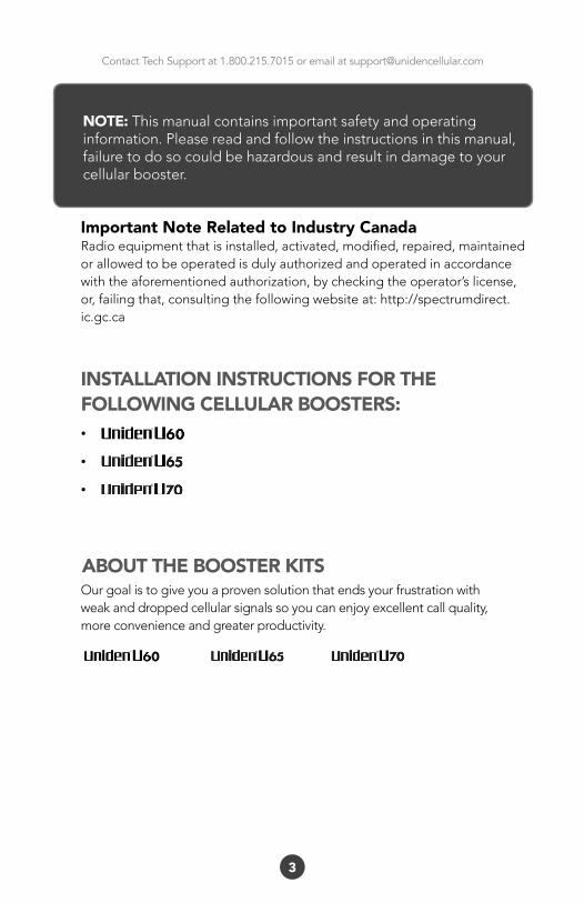
•
•
•
Our goal is to give you a proven solution that ends your frustration withweak and dropped cellular signals so you can enjoy excellent call quality,more convenience and greater productivity.
3
ABOUT THE BOOSTER KITS
INSTALLATION INSTRUCTIONS FOR THE FOLLOWING CELLULAR BOOSTERS:
NOTE: This manual contains important safety and operating information. Please read and follow the instructions in this manual, failure to do so could be hazardous and result in damage to your cellular booster.
Important Note Related to Industry Canada Radio equipment that is installed, activated, modified, repaired, maintained or allowed to be operated is duly authorized and operated in accordance with the aforementioned authorization, by checking the operator’s license, or, failing that, consulting the following website at: http://spectrumdirect.ic.gc.ca
Contact Tech Support at 1.800.215.7015 or email at [email protected]
4
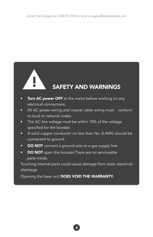
SAFETY AND WARNINGS
• Turn AC power OFF atthemainsbeforeworkingonanyelectricalconnections.
• AllACpowerwiringandcoaxialcablewiringmust conformtolocalornationalcodes.
• TheAClinevoltagemustbewithin10%ofthevoltagespecifiedforthebooster.
• AsolidcopperconductornolessthanNo.8AWGshouldbeconnectedtoground.
• DO NOT connectagroundwiretoagassupplyline.• DO NOT openthebooster.Therearenoserviceablepartsinside.Touchinginternalpartscouldcausedamagefromstaticelectricaldischarge.
OpeningthebaseunitDOES VOID THE WARRANTY.
!
Contact Tech Support at 1.800.215.7015 or email at [email protected]
5
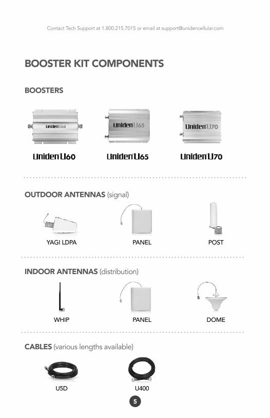
BOOSTER KIT COMPONENTS
BOOSTERS
U400U5D
YAGI LDPA PANEL POST
OUTDOOR ANTENNAS (signal)
WHIP PANEL DOME
INDOOR ANTENNAS(distribution)
CABLES (variouslengthsavailable)
Contact Tech Support at 1.800.215.7015 or email at [email protected]
6
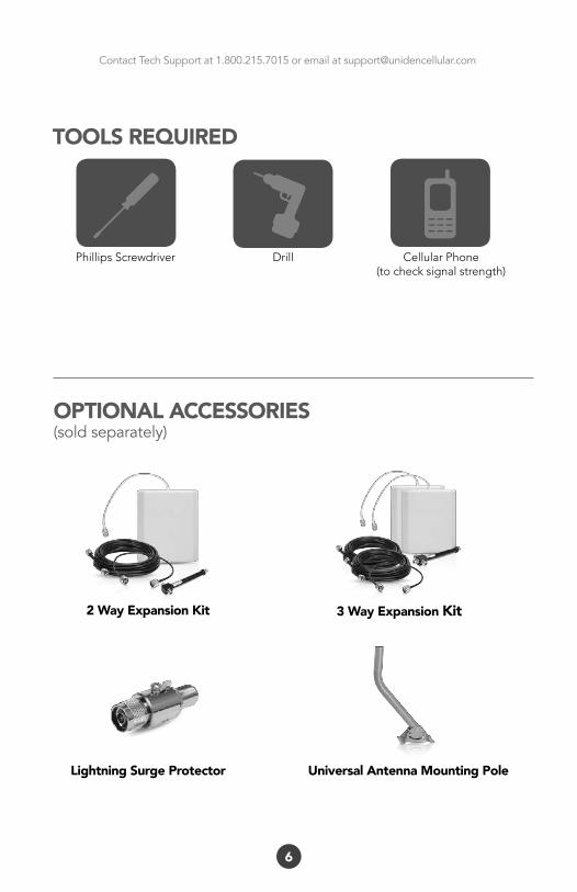
OPTIONAL ACCESSORIES(soldseparately)
2 Way Expansion Kit
Lightning Surge Protector
3 Way Expansion Kit
Universal Antenna Mounting Pole
Phillips Screwdriver Drill Cellular Phone (to check signal strength)
TOOLS REQUIRED
Contact Tech Support at 1.800.215.7015 or email at [email protected]
7
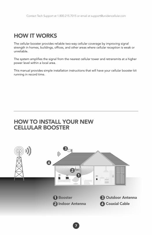
HOW IT WORKSThecellularboosterprovidesreliabletwo-waycellularcoveragebyimprovingsignalstrengthinhomes,buildings,offices,andotherareaswherecellularreceptionisweakorunreliable.
Thesystemamplifiesthesignalfromthenearestcellulartowerandretransmitsatahigherpowerlevelwithinalocalarea.
Thismanualprovidessimpleinstallationinstructionsthatwillhaveyourcellularboosterkitrunninginrecordtime.
HOW TO INSTALL YOUR NEWCELLULAR BOOSTER
1
1
2
2
4
4
3
3BoosterIndoor Antenna
Outdoor AntennaCoaxial Cable
Contact Tech Support at 1.800.215.7015 or email at [email protected]
8
Thisguidewillhelpyouproperlyinstallyourcellularboosterkit.Itisimportanttoreadthroughalloftheinstallationstepsbeforeinstallingyourequipment.Thoroughlyreadthroughtheinstructions,visualizewherealltheequipmentwillneedtobeinstalledanddoasoftinstallationbeforemountinganyequipment.Ifyoudonotunderstandtheinstructionsinfull,pleasecontacttechnicalsupportat 1-800-215-7015.
OVERVIEW
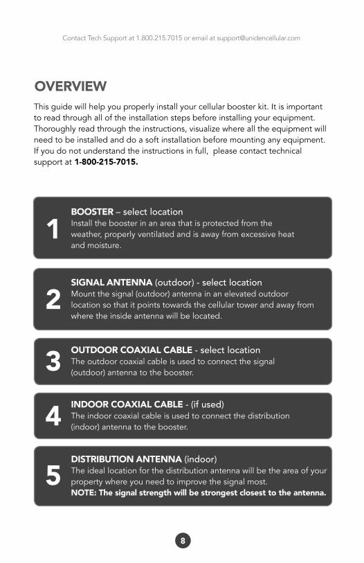
BOOSTER – select locationInstalltheboosterinanareathatisprotectedfromtheweather,properlyventilatedandisawayfromexcessiveheatandmoisture.
1SIGNAL ANTENNA (outdoor) - select locationMountthesignal(outdoor)antennainanelevatedoutdoorlocationsothatitpointstowardsthecellulartowerandawayfromwheretheinsideantennawillbelocated.
2OUTDOOR COAXIAL CABLE - select locationTheoutdoorcoaxialcableisusedtoconnectthesignal(outdoor)antennatothebooster.3INDOOR COAXIAL CABLE - (if used)Theindoorcoaxialcableisusedtoconnectthedistribution(indoor)antennatothebooster.4DISTRIBUTION ANTENNA (indoor)Theideallocationforthedistributionantennawillbetheareaofyourpropertywhereyouneedtoimprovethesignalmost.NOTE: The signal strength will be strongest closest to the antenna.
5
Contact Tech Support at 1.800.215.7015 or email at [email protected]
9
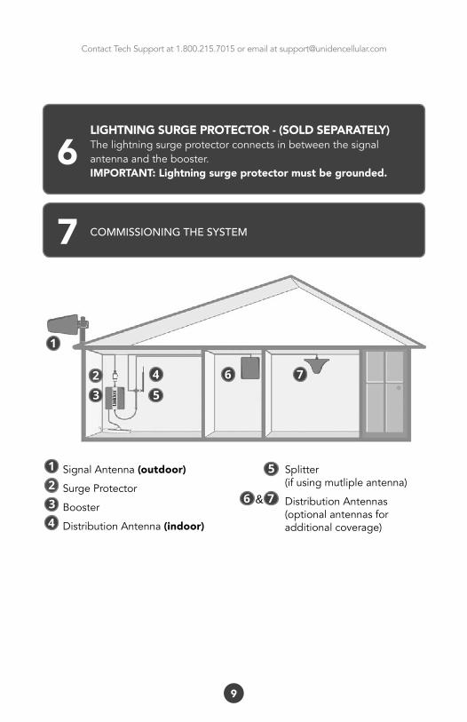
LIGHTNING SURGE PROTECTOR - (SOLD SEPARATELY)Thelightningsurgeprotectorconnectsinbetweenthesignalantennaandthebooster.IMPORTANT: Lightning surge protector must be grounded.
6
7 COMMISSIONING THE SYSTEM
SignalAntenna (outdoor)
SurgeProtector
Booster
DistributionAntenna(indoor)
Splitter(ifusingmutlipleantenna)
DistributionAntennas(optionalantennasforadditionalcoverage)
12
43
1
2 4 6 7
3 5
5
6 7&

Contact Tech Support at 1.800.215.7015 or email at [email protected]
10
Plan the layout of your systemBeforeyougetstartedyouwillneedtoplanthelayoutofyoursystem.Thisinvolvescheckingsignalstrengthforsignalscomingfromthecellulartower,aswellasantenna,boosterandcableplacement.
IDENTIFY THE BEST LOCATION TO INSTALL THE SIGNAL (OUTDOOR) ANTENNA.
Check for signal strengthSelectalocationontheroofofthebuildingtoinstallthesignalantenna,bymonitoringyourcellularphone’ssignalstrength(signalbars)tofindthestrongestsignalfromyourcarrier’scellulartower.
Mark the areaMarkthatareaastheinstallationlocationforthesignal(outdoor).
GETTING STARTED
Contact Tech Support at 1.800.215.7015 or email at [email protected]
11
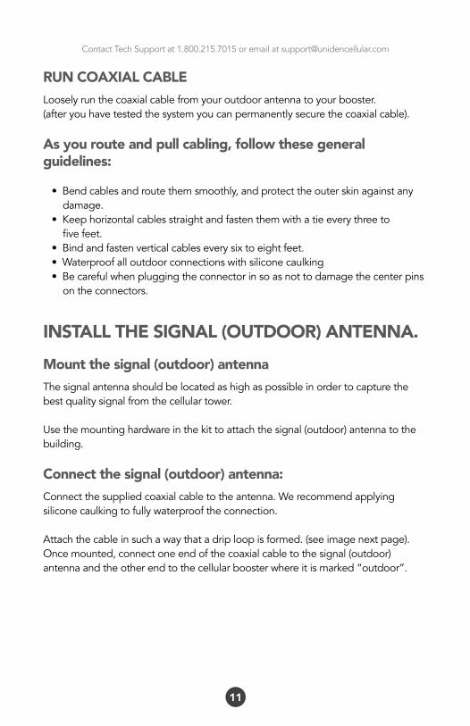
RUN COAXIAL CABLELooselyrunthecoaxialcablefromyouroutdoorantennatoyourbooster.(afteryouhavetestedthesystemyoucanpermanentlysecurethecoaxialcable).
As you route and pull cabling, follow these general guidelines:
•Bendcablesandroutethemsmoothly,andprotecttheouterskinagainstanydamage.•Keephorizontalcablesstraightandfastenthemwithatieeverythreetofivefeet.•Bindandfastenverticalcableseverysixtoeightfeet.•Waterproofalloutdoorconnectionswithsiliconecaulking•Becarefulwhenpluggingtheconnectorinsoasnottodamagethecenterpinsontheconnectors.
INSTALL THE SIGNAL (OUTDOOR) ANTENNA.Mount the signal (outdoor) antenna Thesignalantennashouldbelocatedashighaspossibleinordertocapturethebestqualitysignalfromthecellulartower.
Usethemountinghardwareinthekittoattachthesignal(outdoor)antennatothebuilding.
Connect the signal (outdoor) antenna:Connectthesuppliedcoaxialcabletotheantenna.Werecommendapplyingsiliconecaulkingtofullywaterprooftheconnection.
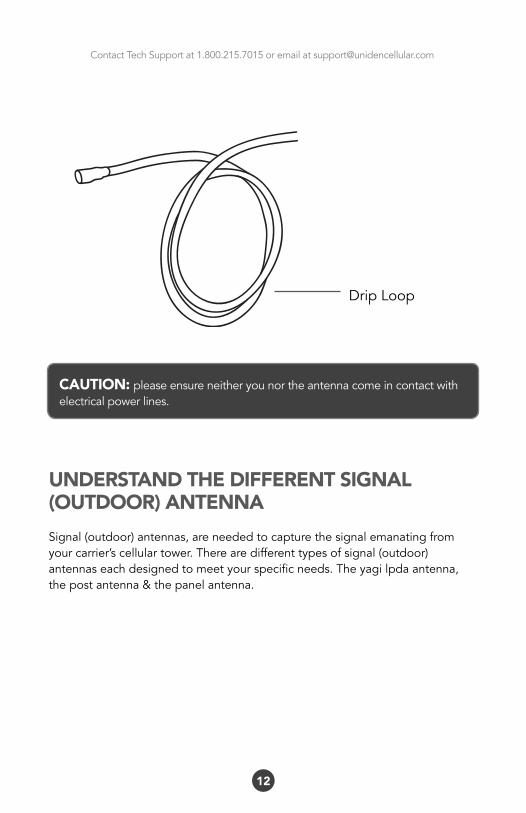
Attachthecableinsuchawaythatadriploopisformed.(seeimagenextpage).Oncemounted,connectoneendofthecoaxialcabletothesignal(outdoor)antennaandtheotherendtothecellularboosterwhereitismarked“outdoor”.
Contact Tech Support at 1.800.215.7015 or email at [email protected]
12
DripLoop
CAUTION: pleaseensureneitheryounortheantennacomeincontactwithelectricalpowerlines.
UNDERSTAND THE DIFFERENT SIGNAL (OUTDOOR) ANTENNASignal(outdoor)antennas,areneededtocapturethesignalemanatingfromyourcarrier’scellulartower.Therearedifferenttypesofsignal(outdoor)antennaseachdesignedtomeetyourspecificneeds.Theyagilpdaantenna,thepostantenna&thepanelantenna.
Contact Tech Support at 1.800.215.7015 or email at [email protected]
13
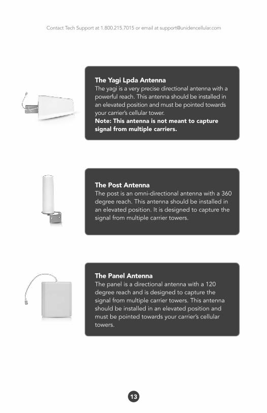
The Yagi Lpda AntennaTheyagiisaveryprecisedirectionalantennawithapowerfulreach.Thisantennashouldbeinstalledinanelevatedpositionandmustbepointedtowardsyourcarrier’scellulartower.Note: This antenna is not meant to capture signal from multiple carriers.
The Post AntennaThepostisanomni-directionalantennawitha360degreereach.Thisantennashouldbeinstalledinanelevatedposition.Itisdesignedtocapturethesignalfrommultiplecarriertowers.
The Panel AntennaThepanelisadirectionalantennawitha120degreereachandisdesignedtocapturethesignalfrommultiplecarriertowers.Thisantennashouldbeinstalledinanelevatedpositionandmustbepointedtowardsyourcarrier’scellulartowers.
Contact Tech Support at 1.800.215.7015 or email at [email protected]
Thelightningsurgeprotectorcanbeinstalledindoorsoroutdoors.Whenconnectingoutdoors,installthelightningsurgeprotectorinlinebetweenthesignalantenna(outdoor)andthecoaxialcable.Whenconnectingindoors,installthelightningsurgeprotectorinlinebetweentheoutdoorcoaxialcableandthebooster.
INSTALL THE DISTRIBUTION (INDOOR) ANTENNASelecttheinstallationlocationofyoursupplieddistribution(indoor)antennabasedonthefollowing:
Dome omni directional antennaPlaceinthecenteroftheareawherethesignalneedstobeamplified.
Panel directional antennaePlaceintheouterperimeteroftheareathesignalneedstobeamplified.
Whip omni directional antenna Mountdirectlytotheconnectormarked“indoor”onthecellularbooster.
14
LIGHTNING SURGE PROTECTOR(sold separately)
IMPORTANT: Lightningsurgeprotectormustbegrounded.Connectagroundwiretotheappropriateplaceonthelightningsurgeprotectorandconnecttheotherendtoaverifiedgroundsource.
!
Contact Tech Support at 1.800.215.7015 or email at [email protected]
15
CONNECTING THE DISTRIBUTION (INDOOR) ANTENNADome omni directional antenna Connectoneendofthecoaxialcabletothedomeantennaandtheotherendtothecellularboosterwhereitismarked“indoor”.
Panel directional antenna Connectoneendofthecoaxialcabletothepanelantennaandtheotherendtotheconnectoronthecellularboosterwhereitismarked“indoor”.
Whip omni directional antenna Connecttheantenna’senddirectlytotheconnectoronthecellularboosterwhereitismarked“indoor”.
Contact Tech Support at 1.800.215.7015 or email at [email protected]
16
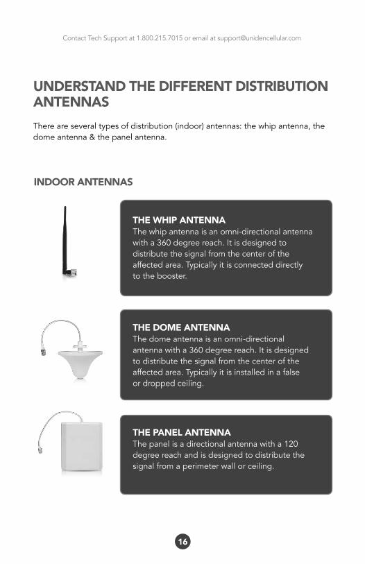
UNDERSTAND THE DIFFERENT DISTRIBUTION ANTENNASThereareseveraltypesofdistribution(indoor)antennas:thewhipantenna,thedomeantenna&thepanelantenna.
INDOOR ANTENNAS
THE WHIP ANTENNAThewhipantennaisanomni-directionalantennawitha360degreereach.Itisdesignedtodistributethesignalfromthecenteroftheaffectedarea.Typicallyitisconnecteddirectlytothebooster.
THE DOME ANTENNAThedomeantennaisanomni-directionalantennawitha360degreereach.Itisdesignedtodistributethesignalfromthecenteroftheaffectedarea.Typicallyitisinstalledinafalseordroppedceiling.
THE PANEL ANTENNAThepanelisadirectionalantennawitha120degreereachandisdesignedtodistributethesignalfromaperimeterwallorceiling.
Contact Tech Support at 1.800.215.7015 or email at [email protected]
17
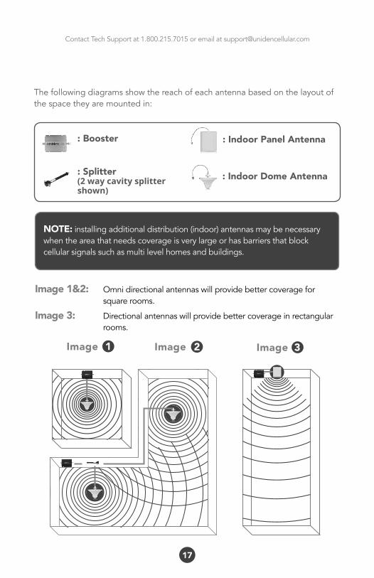
Thefollowingdiagramsshowthereachofeachantennabasedonthelayoutofthespacetheyaremountedin:
Image1Image 32
: Indoor Panel Antenna: Booster
: Splitter(2 way cavity splittershown)
Image
NOTE:installingadditionaldistribution(indoor)antennasmaybenecessarywhentheareathatneedscoverageisverylargeorhasbarriersthatblockcellularsignalssuchasmultilevelhomesandbuildings.
: Indoor Dome Antenna
Image 1&2: Omnidirectionalantennaswillprovidebettercoveragefor squarerooms.
Image 3: Directionalantennaswillprovidebettercoverageinrectangular rooms.
Contact Tech Support at 1.800.215.7015 or email at [email protected]
18
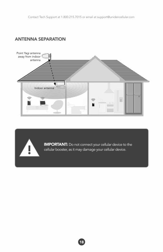
IMPORTANT: Donotconnectyourcellulardevicetothecellularbooster,asitmaydamageyourcellulardevice.
ANTENNA SEPARATION
!
PointYagiantennaawayfromindoor
antenna
Indoorantenna

Contact Tech Support at 1.800.215.7015 or email at [email protected]
19
INSTALL YOUR CELLULAR BOOSTERInstallthecellularboosterinalocationthatisproperlyventilatedandnotexposedtoexcessiveheat,moistureand/ordirectsunlight.Theoptimalareawouldbeonawalllocatednearapoweroutlet.
Itshouldbemountedinaneasilyaccessibleareasoit’seasytoperformgeneralmaintenancewiththecoaxialcableconnections,dipswitchsettingsandpoweradaptor.
Makesureallcablesandantennasaresecurelyconnectedbeforecommissioningthesystem.
POWER UP YOUR CELLULAR BOOSTEROnceallthenextpageprecautionshavebeentaken,poweronthecellularbooster.
TheLEDindicatormarkedpowershouldlightupgreen.
Contact Tech Support at 1.800.215.7015 or email at [email protected]
20
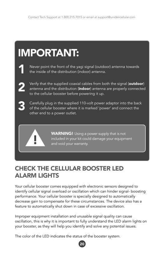
IMPORTANT:1 Neverpointthefrontoftheyagisignal(outdoor)antennatowards
theinsideofthedistribution(indoor)antenna.
2 Verifythatthesuppliedcoaxialcablesfromboththesignal(outdoor)antennaandthedistribution(indoor)antennaareproperlyconnectedtothecellularboosterbeforepoweringitup.
3 Carefullypluginthesupplied110-voltpoweradaptorintothebackofthecellularboosterwhereitismarked‘power’andconnecttheotherendtoapoweroutlet.
WARNING! Usingapowersupplythatisnotincludedinyourkitcoulddamageyourequipmentandvoidyourwarranty.
CHECK THE CELLULAR BOOSTER LEDALARM LIGHTSYourcellularboostercomesequippedwithelectronicsensorsdesignedtoidentifycellularsignaloverloadoroscillationwhichcanhindersignal-boostingperformance.Yourcellularboosterisspeciallydesignedtoautomaticallydecreasegaintocompensateforthesecircumstances.Thedevicealsohasafeaturetoautomaticallyshutdownincaseofexcessiveoscillation.
Improperequipmentinstallationandunusablesignalqualitycancauseoscillation,thisiswhyitisimportanttofullyunderstandtheLEDalarmlightsonyourbooster,astheywillhelpyouidentifyandsolveanypotentialissues.
ThecoloroftheLEDindicatesthestatusoftheboostersystem.
!
Contact Tech Support at 1.800.215.7015 or email at [email protected]
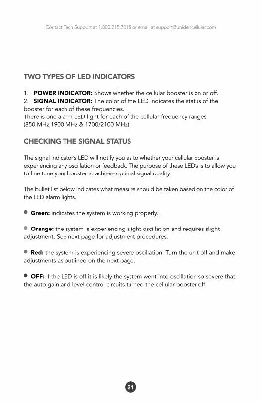
TWO TYPES OF LED INDICATORS
1. POWER INDICATOR: Showswhetherthecellularboosterisonoroff.2.SIGNAL INDICATOR:ThecoloroftheLEDindicatesthestatusoftheboosterforeachofthesefrequencies.ThereisonealarmLEDlightforeachofthecellularfrequencyranges(850MHz,1900MHz&1700/2100MHz).
CHECKING THE SIGNAL STATUS
Thesignalindicator’sLEDwillnotifyyouastowhetheryourcellularboosterisexperiencinganyoscillationorfeedback.ThepurposeoftheseLED’sistoallowyoutofinetuneyourboostertoachieveoptimalsignalquality.
ThebulletlistbelowindicateswhatmeasureshouldbetakenbasedonthecoloroftheLEDalarmlights.
Green:indicatesthesystemisworkingproperly..
Orange:thesystemisexperiencingslightoscillationandrequiresslightadjustment.Seenextpageforadjustmentprocedures.
Red:thesystemisexperiencingsevereoscillation.Turntheunitoffandmakeadjustmentsasoutlinedonthenextpage.
OFF:iftheLEDisoffitislikelythesystemwentintooscillationsoseverethattheautogainandlevelcontrolcircuitsturnedthecellularboosteroff.
21
Contact Tech Support at 1.800.215.7015 or email at [email protected]
22
ADJUSTING THE MANUAL GAIN CONTROL:
Themanualgaincontrol(MGC)adjuststheoverallamplificationlevel(gain)ofthebooster.TheManualGainControlisusedtoresolvetheissueofoscillationwithouttheneedofreadjustingyourantennas,inmostcases.
TheMGCallowsyoutoeasilyreducetheamountofgain(amplification)theboosterisemitting.Thisisdonewithasetofdipswitchesonthesideofthebooster.Thereareaseriesofdipswitchestoadjusttheuplinkandanothersettoadjustthedownlink.
Therearetwosetsofdipswitches,oneislabeled“1900MHz”andtheotherlabeled“850MHz”.Eachsetisdividedbetweenthedownlinkandtheuplink.Thedipswitches,whenputintothe“ON”positionwillreducethegainoftheboosterforthedesignatedfrequencyandtransmissiondirection.WhentheLEDalarmsindicateoscillation(turnsorange,redoroff)youneedtoreducethegainofthedownlinkandtheuplinkfortheappropriatefrequency.Dothisgraduallyinordertodeterminetheideallevel.
ADJUSTING THE UPLINKPleasefollowtheseproceduresforeachfrequency.
IfthealarmLEDturnsoffimmediatelyaftercommissioningthesystem,thesignalontheuplinkislikelytoostrong.Takemeasurestoreducetheuplinkgain.Continuetoincreasethegainreductionuntilthealarmlightchangestogreen.
ADJUSTING THE DOWNLINKOnceyouhavefine-tunedtheuplinksignal,itistimetoadjustthedownlink.IfthealarmLEDisgreenyouareallset.IfthealarmLEDisorange,youwillonlyneedtoreducethegainslightly.IfthealarmLEDisred,youwillneedtogreatlyreducethegain.Asyouimplementthegainreductions,theLEDalarmsshouldchangefromredororangetogreen.
Contact Tech Support at 1.800.215.7015 or email at [email protected]
MGC DIP SWITCH CONTROL FOR
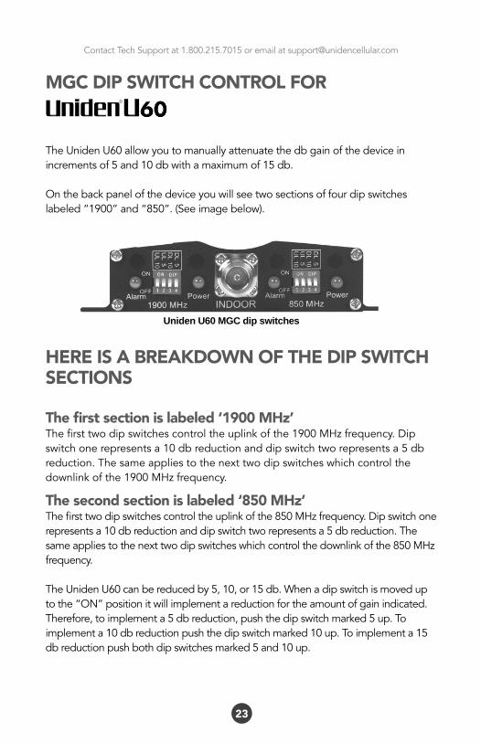
TheUnidenU60allowyoutomanuallyattenuatethedbgainofthedeviceinincrementsof5and10dbwithamaximumof15db.
Onthebackpanelofthedeviceyouwillseetwosectionsoffourdipswitcheslabeled“1900”and“850”.(Seeimagebelow).
HERE IS A BREAKDOWN OF THE DIP SWITCH SECTIONS
The first section is labeled ‘1900 MHz’Thefirsttwodipswitchescontroltheuplinkofthe1900MHzfrequency.Dipswitchonerepresentsa10dbreductionanddipswitchtworepresentsa5dbreduction.Thesameappliestothenexttwodipswitcheswhichcontrolthedownlinkofthe1900MHzfrequency.
The second section is labeled ‘850 MHz’Thefirsttwodipswitchescontroltheuplinkofthe850MHzfrequency.Dipswitchonerepresentsa10dbreductionanddipswitchtworepresentsa5dbreduction.Thesameappliestothenexttwodipswitcheswhichcontrolthedownlinkofthe850MHzfrequency.
TheUnidenU60canbereducedby5,10,or15db.Whenadipswitchismoveduptothe“ON”positionitwillimplementareductionfortheamountofgainindicated.Therefore,toimplementa5dbreduction,pushthedipswitchmarked5up.Toimplementa10dbreductionpushthedipswitchmarked10up.Toimplementa15dbreductionpushbothdipswitchesmarked5and10up.
23
Uniden U60 MGC dip switches
Contact Tech Support at 1.800.215.7015 or email at [email protected]
24
ADJUSTING MANUAL GAIN CONTROL
Themanualgaincontrol(MGC)adjuststheoverallamplificationlevel(gain)ofthebooster.TheManualGainControlisusedtoresolvetheissueofoscillationwithouttheneedofreadjustingyourantennas,inmostcases.
TheMGCallowsyoutoeasilyreducetheamountofgain(amplification)theboosterisemitting.Thisisdonewithasetofdipswitchesonthesideofthebooster.Thereareaseriesofdipswitchestoadjusttheuplinkandanothersettoadjustthedownlink.
Therearetwosetsofdipswitches,oneislabeled“1900MHz”andtheotherlabeled“850MHz”.Eachsetisdividedbetweenthedownlinkandtheuplink.Thedipswitches,whenputintothe“ON”positionwillreducethegainoftheboosterforthedesignatedfrequencyandtransmissiondirection.WhentheLEDalarmsindicateoscillation(turnsorange,redoroff)youneedtoreducethegainofthedownlinkandtheuplinkfortheappropriatefrequency.Dothisgraduallyinordertodeterminetheideallevel.
ADJUSTING THE UPLINKPleasefollowtheseproceduresforeachfrequency.
IfthealarmLEDturnsoffimmediatelyaftercommissioningthesystem,thesignalontheuplinkislikelytoostrong.Takemeasurestoreducetheuplinkgain.Continuetoincreasethegainreductionuntilthealarmlightchangestogreen.
ADJUSTING THE DOWNLINKOnceyouhavefine-tunedtheuplinksignal,itistimetoadjustthedownlink.IfthealarmLEDisgreenyouareallset.IfthealarmLEDisorange,youwillonlyneedtoreducethegainslightly.IfthealarmLEDisred,youwillneedtogreatlyreducethegain.Asyouimplementthegainreductions,theLEDalarmsshouldchangefromredororangetogreen.
Contact Tech Support at 1.800.215.7015 or email at [email protected]
MGC DIP SWITCH CONTROL FOR
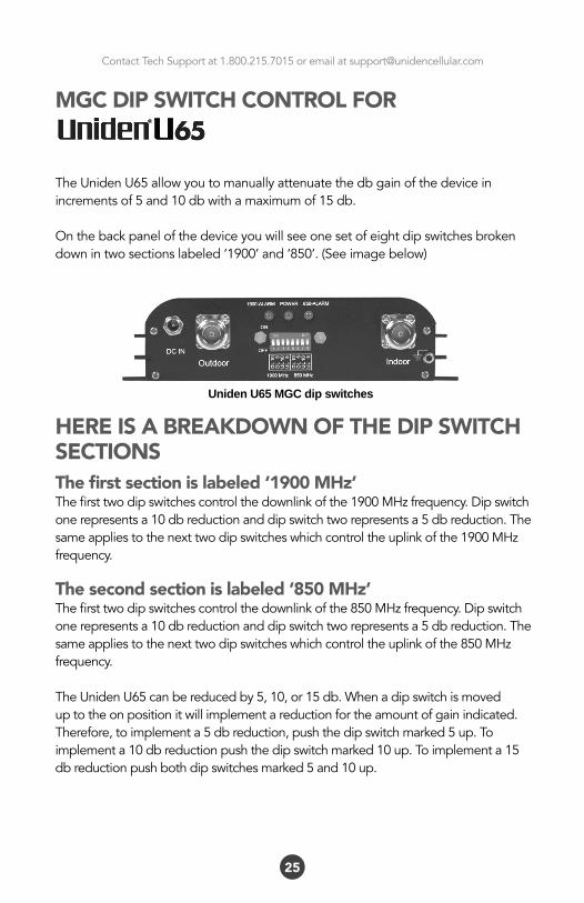
TheUnidenU65allowyoutomanuallyattenuatethedbgainofthedeviceinincrementsof5and10dbwithamaximumof15db.
Onthebackpanelofthedeviceyouwillseeonesetofeightdipswitchesbrokendownintwosectionslabeled‘1900’and‘850’.(Seeimagebelow)
HERE IS A BREAKDOWN OF THE DIP SWITCH SECTIONSThe first section is labeled ‘1900 MHz’Thefirsttwodipswitchescontrolthedownlinkofthe1900MHzfrequency.Dipswitchonerepresentsa10dbreductionanddipswitchtworepresentsa5dbreduction.Thesameappliestothenexttwodipswitcheswhichcontroltheuplinkofthe1900MHzfrequency.
The second section is labeled ‘850 MHz’Thefirsttwodipswitchescontrolthedownlinkofthe850MHzfrequency.Dipswitchonerepresentsa10dbreductionanddipswitchtworepresentsa5dbreduction.Thesameappliestothenexttwodipswitcheswhichcontroltheuplinkofthe850MHzfrequency.
TheUnidenU65canbereducedby5,10,or15db.Whenadipswitchismoveduptotheonpositionitwillimplementareductionfortheamountofgainindicated.Therefore,toimplementa5dbreduction,pushthedipswitchmarked5up.Toimplementa10dbreductionpushthedipswitchmarked10up.Toimplementa15dbreductionpushbothdipswitchesmarked5and10up.
25
Uniden U65 MGC dip switches
Contact Tech Support at 1.800.215.7015 or email at [email protected]
26
Themanualgaincontrol(MGC)adjuststheoverallamplificationlevel(gain)ofthebooster.TheManualGainControlisusedtoresolvetheissueofoscillationwithouttheneedofreadjustingyourantennas,inmostcases.
TheMGCallowsyoutoeasilyreducetheamountofgain(amplification)theboosterisemitting.Thisisdonewithasetofdipswitchesonthesideofthebooster.Thereareaseriesofdipswitchestoadjusttheuplinkandanothersettoadjustthedownlink.
Therearefoursetsofdipswitches,oneislabeled“CDMA”andtheotherlabeled“PCS”.Eachsetisdividedbetweenthedownlinkandtheuplink.Thedipswitches,whenputintothe“ON”positionwillreducethegainoftheboosterforthedesignatedfrequencyandtransmissiondirection.WhentheLEDalarmsindicateoscillation(turnsorange,redoroff)youneedtoreducethegainofthedownlinkandtheuplinkfortheappropriatefrequency.Dothisgraduallyinordertodeterminetheideallevel.
ADJUSTING THE UPLINKPleasefollowtheseproceduresforeachfrequency.
IfthealarmLEDturnsoffimmediatelyaftercommissioningthesystem,thesignalontheuplinkislikelytoostrong.Takemeasurestoreducetheuplinkgain.Continuetoincreasethegainreductionuntilthealarmlightchangestogreen.
ADJUSTING THE DOWNLINKOnceyouhavefine-tunedtheuplinksignal,itistimetoadjustthedownlink.IfthealarmLEDisgreenyouareallset.IfthealarmLEDisorange,youwillonlyneedtoreducethegainslightly.IfthealarmLEDisred,youwillneedtogreatlyreducethegain.Asyouimplementthegainreductions,theLEDalarmsshouldchangefromredororangetogreen.
ADJUSTING MANUAL GAIN CONTROL:
Contact Tech Support at 1.800.215.7015 or email at [email protected]
27
MGC DIP SWITCH CONTROL FOR
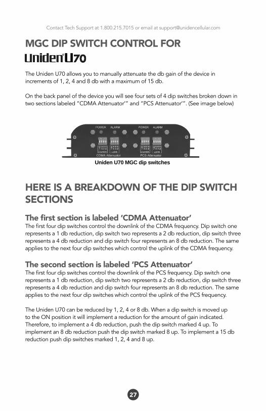
TheUnidenU70allowsyoutomanuallyattenuatethedbgainofthedeviceinincrementsof1,2,4and8dbwithamaximumof15db.
Onthebackpanelofthedeviceyouwillseefoursetsof4dipswitchesbrokendownintwosectionslabeled“CDMAAttenuator’”and“PCSAttenuator’”.(Seeimagebelow)
HERE IS A BREAKDOWN OF THE DIP SWITCH SECTIONSThe first section is labeled ‘CDMA Attenuator’ThefirstfourdipswitchescontrolthedownlinkoftheCDMAfrequency.Dipswitchonerepresentsa1dbreduction,dipswitchtworepresentsa2dbreduction,dipswitchthreerepresentsa4dbreductionanddipswitchfourrepresentsan8dbreduction.ThesameappliestothenextfourdipswitcheswhichcontroltheuplinkoftheCDMAfrequency.
The second section is labeled ‘PCS Attenuator’ThefirstfourdipswitchescontrolthedownlinkofthePCSfrequency.Dipswitchonerepresentsa1dbreduction,dipswitchtworepresentsa2dbreduction,dipswitchthreerepresentsa4dbreductionanddipswitchfourrepresentsan8dbreduction.ThesameappliestothenextfourdipswitcheswhichcontroltheuplinkofthePCSfrequency.
TheUnidenU70canbereducedby1,2,4or8db.WhenadipswitchismoveduptotheONpositionitwillimplementareductionfortheamountofgainindicated.Therefore,toimplementa4dbreduction,pushthedipswitchmarked4up.Toimplementan8dbreductionpushthedipswitchmarked8up.Toimplementa15dbreductionpushdipswitchesmarked1,2,4and8up.
Uniden U70 MGC dip switches
Contact Tech Support at 1.800.215.7015 or email at [email protected]
28
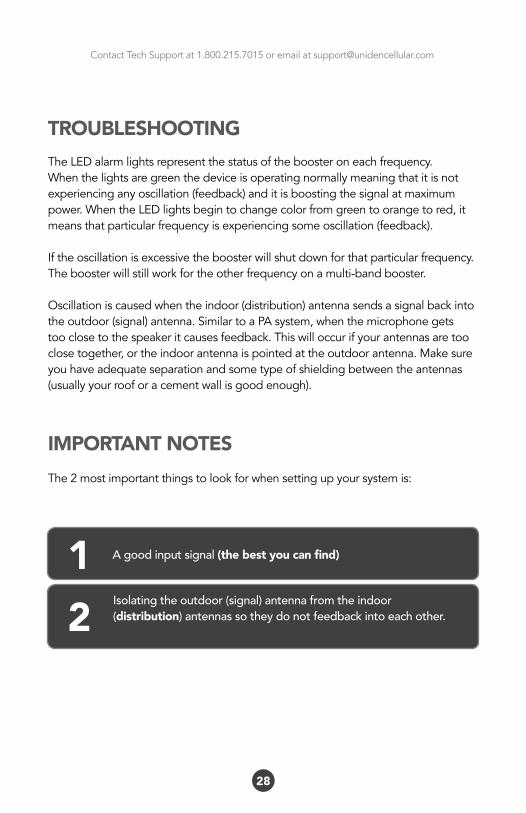
TROUBLESHOOTINGTheLEDalarmlightsrepresentthestatusoftheboosteroneachfrequency.Whenthelightsaregreenthedeviceisoperatingnormallymeaningthatitisnotexperiencinganyoscillation(feedback)anditisboostingthesignalatmaximumpower.WhentheLEDlightsbegintochangecolorfromgreentoorangetored,itmeansthatparticularfrequencyisexperiencingsomeoscillation(feedback).
Iftheoscillationisexcessivetheboosterwillshutdownforthatparticularfrequency.Theboosterwillstillworkfortheotherfrequencyonamulti-bandbooster.
Oscillationiscausedwhentheindoor(distribution)antennasendsasignalbackintotheoutdoor(signal)antenna.SimilartoaPAsystem,whenthemicrophonegetstooclosetothespeakeritcausesfeedback.Thiswilloccurifyourantennasaretooclosetogether,ortheindoorantennaispointedattheoutdoorantenna.Makesureyouhaveadequateseparationandsometypeofshieldingbetweentheantennas(usuallyyourrooforacementwallisgoodenough).
IMPORTANT NOTESThe2mostimportantthingstolookforwhensettingupyoursystemis:
A good input signal (the best you can find)1Isolating the outdoor (signal) antenna from the indoor(distribution) antennas so they do not feedback into each other. 2
Contact Tech Support at 1.800.215.7015 or email at [email protected]
29
Bycapturingthebestinputsignalyouwillbeabletoenjoythemaximumcoverageandbestqualitysignalinsidewhereyourdistributionantennasarelocated.Thebettertheinputsignal,thebettertheoutputsignal.Inordertofindthebestinputsignal,youwanttoplaceyouroutdoor(signal)antennaashighaspossiblewiththeleastamountofobstructionbetweentheantennaandthecellularbasetower.Aclearlineofsiteisideal.
Isolatingthesignalfromtheantennasisdonebyensuringthattheantennasarenotpointingtoeachotherandbyhavingenoughdistanceorbarriershieldinginbetweenthem.Thesignalstravellikeraysofsunlight,adirectionalantennawillsendthesignalinthedirectionthatitispointing.Anomnidirectionalantennawillsendthesignalineverydirectionaroundit.Sodependingonyourequipmentitsimportanttobesurethatyourdistributionantenna(indoor)isnotsendingthesignalbackintotheoutdoor(signal)antenna.
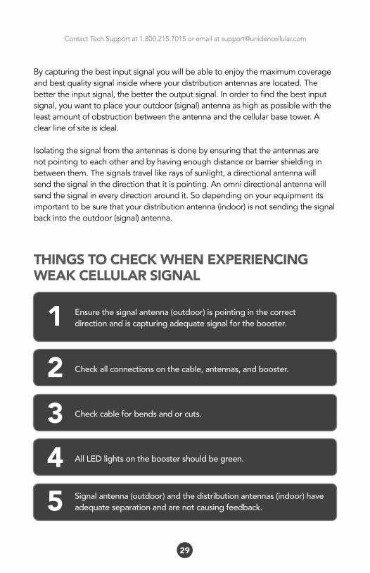
THINGS TO CHECK WHEN EXPERIENCING WEAK CELLULAR SIGNAL
Check all connections on the cable, antennas, and booster.2Check cable for bends and or cuts.3All LED lights on the booster should be green.4
Ensure the signal antenna (outdoor) is pointing in the correct direction and is capturing adequate signal for the booster.1
Signal antenna (outdoor) and the distribution antennas (indoor) have adequate separation and are not causing feedback.5
Contact Tech Support at 1.800.215.7015 or email at [email protected]
30
FREQUENTLY ASKED QUESTIONS
WHY ARE THE LED LIGHTS TURNING ORANGE, RED OR SHUTTING OFF?
Therearecertaincaseswhereyoursystemcouldbeexperiencingoscillation.Thiscanbeattributedtoeitherthequalityofyourinputsignalorhavingyoursignal(outdoor)antennaanddistribution(indoor)antennatooclosetogether.Pleasereviewthefollowingguidelinestohelpresolvethisissue:
1.Adjustthedirectionofthesignal(outdoor)antenna.Ifthesystemisreceivingaveryhighinputsignal,youcanpointyoursignal(outdoor)antennaawayfromthecellulartowertoreducethestrengthoftheinputsignalandtherefore,reducetheoscillation.Alternativelyifyoursystemisreceivingaverypoorqualitysignal(weakandunusablesignal),youcanpointyoursignal(outdoor)antennamoredirectlytowardsthecellulartowertoincreasethestrengthoftheinputsignal.Sometimesthismayrequirecompletelyrepositioningtheantennatoalocationwhereyoucanachievealineofsitetothetower.
2.Increasetheseparationbetweenthesignal(outdoor)antennaandthedistribution(indoor)antenna.Thiscanbeachievedbyincreasingthedistancebetweenthetwoantennasorbyplacingbarriersbetweenthem,suchasmovingthedistribution(indoor)antennatoanadjacentroomwheretherewouldbeanadditionalwallseparatingthemfromthesignal(outdoor)antenna.
3.ManualGainControl.Adjustthegainwiththemanualgaincontrolfunctionusingthedipswitchesonthesideofthebooster.
See page 22 for more details.
Contact Tech Support at 1.800.215.7015 or email at [email protected]
31
I INSTALLED THE BOOSTER AND MY SIGNAL STRENGTH IS STILL WEAK
Inordertocorrectaweaksignal;essentiallyyouhavetheoptionsof:
• Adjusttheaimofthesignal(outdoor)antennaorreplaceitwithahigher gainantenna.• Movethedistribution(indoor)antenna.• Increasethenumberofdistribution(indoor)antennas.• Reducingtheattenuationvaluesyouchosewhensettingthemanualgain control.
I CANNOT MAINTAIN CALLS, MY SIGNAL STRENGTH FLUCTUATES
Ifyoufindtheboosterisworkingbutdropscallsordeliversfluctuatingsignallevels,themostlikelycauseisoscillationbetweenthesignalanddistributionantenna(s).
Determinethestatusofthecellularboosterledalarms.Ifsothereisinsufficientisolationbetweenantennas.Youcaneitherincreasethedistancebetweenantennasorplacebarriersbetweenthemtoattenuatethesignalsoradjustthemanualgaincontrolsettings.
Asecondcauseforthissymptomispoorcableconnections.Confirmthatallcableconnectionsaretightandsecure.
Athirdcausemaybeinterferencefromothercellularserviceprovidersoperatinginthesamefrequencybands.Iftheirsignalsarestrongerthanthecellularsignalsyouwanttoreceivefromthecelltower.Inthiscasetheunwantedsignalneedstobeattenuatedeitherbyrepositioningorre-aligningthesignal(outdoor)antenna,orbyusingbarriers(buildings,trees,etc)toblockthesignal.
Contact Tech Support at 1.800.215.7015 or email at [email protected]
32
MY LED’S ARE ALL GREEN BUT MY SIGNAL IS STILL WEAK - MY COVERAGE IS POOR
Ifyoureceiveasignalwhereyoudidnotpreviously...or,iftheradiusoftheserviceareacoveredissmall...andyourLED’sareallgreen...theboosterisworkingproperlybutforsomereasonthesignalisnotverystrong.Thiscanbeduetoweakinputsignal.
• Adjustyoursignal(outdoor)antennatopointmoreaccuratelyatthe cellulartowerinordertoincreasetheinputsignal.
• Checkthecoaxialcabletoensuretherearenotanycreasesorcutsinit. Perhapsthecablewasdamagedduringinstallation.
WHY ISN’T MY CELL PHONE INDICATING MORE SIGNAL WITH MORE BARS?
Youmaynotalwaysobservemorebarsonyoursignalmeterbecauseofthesignalspreadingoutfromtheantenna.Ifyourphonehasadbmeter,3dbisasignificantincreaseof2times,6dbis4times,and10dbis10times.onafourbarphone,one“bar”equalsabout10db.
Theincreaseinsignalyouwillseedependsupon:
• Thelevelofsignalatthesignal(outdoor)antenna
• Thecareoftheantennaplacement(2feetawayfrommetal,adequate antennaseparation[30feetrecommended]).
• Thedistanceofyourphone/devicefromthedistribution(indoor) antenna(signalspreadsordiminishesrapidlywithdistance.)

Contact Tech Support at 1.800.215.7015 or email at [email protected]
33
NOTESModel #:Serial #:Date: Purchased from:Notes:

Contact Tech Support at 1.800.215.7015 or email at [email protected]
34
NOTESModel #:Serial #:Date: Purchased from:Notes:
Contact Tech Support at 1.800.215.7015 or email at [email protected]
35
NOTESModel #:Serial #:Date: Purchased from:Notes:
Contact Tech Support at 1.800.215.7015 or email at [email protected]
INSTRUCTION MANUAL
Phone: 1-800-215-7015 Email: [email protected]
www.unidencellular.com
TheUnidentrademarkisownedbyUnidenAmericaCorporationanditsaffiliatesisusedunderlicensebySignifiMobile.