Embed Size (px)
Citation preview
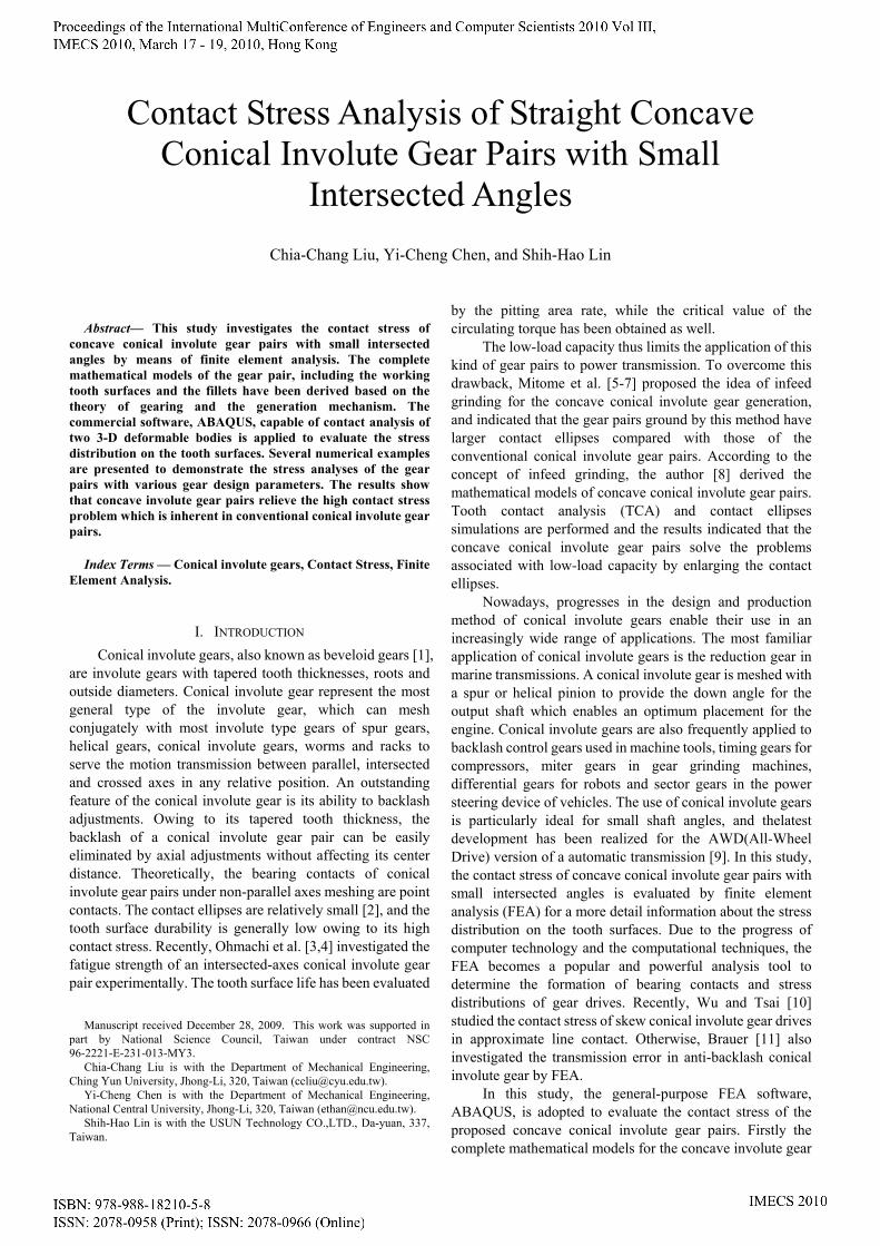
Abstract— This study investigates the contact stress of
concave conical involute gear pairs with small intersected angles by means of finite element analysis. The complete mathematical models of the gear pair, including the working tooth surfaces and the fillets have been derived based on the theory of gearing and the generation mechanism. The commercial software, ABAQUS, capable of contact analysis of two 3-D deformable bodies is applied to evaluate the stress distribution on the tooth surfaces. Several numerical examples are presented to demonstrate the stress analyses of the gear pairs with various gear design parameters. The results show that concave involute gear pairs relieve the high contact stress problem which is inherent in conventional conical involute gear pairs.
Index Terms — Conical involute gears, Contact Stress, Finite Element Analysis.
I. INTRODUCTION Conical involute gears, also known as beveloid gears [1],
are involute gears with tapered tooth thicknesses, roots and outside diameters. Conical involute gear represent the most general type of the involute gear, which can mesh conjugately with most involute type gears of spur gears, helical gears, conical involute gears, worms and racks to serve the motion transmission between parallel, intersected and crossed axes in any relative position. An outstanding feature of the conical involute gear is its ability to backlash adjustments. Owing to its tapered tooth thickness, the backlash of a conical involute gear pair can be easily eliminated by axial adjustments without affecting its center distance. Theoretically, the bearing contacts of conical involute gear pairs under non-parallel axes meshing are point contacts. The contact ellipses are relatively small [2], and the tooth surface durability is generally low owing to its high contact stress. Recently, Ohmachi et al. [3,4] investigated the fatigue strength of an intersected-axes conical involute gear pair experimentally. The tooth surface life has been evaluated
Manuscript received December 28, 2009. This work was supported in
part by National Science Council, Taiwan under contract NSC 96-2221-E-231-013-MY3.
Chia-Chang Liu is with the Department of Mechanical Engineering, Ching Yun University, Jhong-Li, 320, Taiwan ([email protected]).
Yi-Cheng Chen is with the Department of Mechanical Engineering, National Central University, Jhong-Li, 320, Taiwan ([email protected]).
Shih-Hao Lin is with the USUN Technology CO.,LTD., Da-yuan, 337, Taiwan.
by the pitting area rate, while the critical value of the circulating torque has been obtained as well.
The low-load capacity thus limits the application of this kind of gear pairs to power transmission. To overcome this drawback, Mitome et al. [5-7] proposed the idea of infeed grinding for the concave conical involute gear generation, and indicated that the gear pairs ground by this method have larger contact ellipses compared with those of the conventional conical involute gear pairs. According to the concept of infeed grinding, the author [8] derived the mathematical models of concave conical involute gear pairs. Tooth contact analysis (TCA) and contact ellipses simulations are performed and the results indicated that the concave conical involute gear pairs solve the problems associated with low-load capacity by enlarging the contact ellipses.
Nowadays, progresses in the design and production method of conical involute gears enable their use in an increasingly wide range of applications. The most familiar application of conical involute gears is the reduction gear in marine transmissions. A conical involute gear is meshed with a spur or helical pinion to provide the down angle for the output shaft which enables an optimum placement for the engine. Conical involute gears are also frequently applied to backlash control gears used in machine tools, timing gears for compressors, miter gears in gear grinding machines, differential gears for robots and sector gears in the power steering device of vehicles. The use of conical involute gears is particularly ideal for small shaft angles, and thelatest development has been realized for the AWD(All-Wheel Drive) version of a automatic transmission [9]. In this study, the contact stress of concave conical involute gear pairs with small intersected angles is evaluated by finite element analysis (FEA) for a more detail information about the stress distribution on the tooth surfaces. Due to the progress of computer technology and the computational techniques, the FEA becomes a popular and powerful analysis tool to determine the formation of bearing contacts and stress distributions of gear drives. Recently, Wu and Tsai [10] studied the contact stress of skew conical involute gear drives in approximate line contact. Otherwise, Brauer [11] also investigated the transmission error in anti-backlash conical involute gear by FEA.
In this study, the general-purpose FEA software, ABAQUS, is adopted to evaluate the contact stress of the proposed concave conical involute gear pairs. Firstly the complete mathematical models for the concave involute gear
Contact Stress Analysis of Straight Concave Conical Involute Gear Pairs with Small
Intersected Angles Chia-Chang Liu, Yi-Cheng Chen, and Shih-Hao Lin

pairs, including the working tooth surfaces and the fillets, have been developed based on the theory of gearing and the generation mechanism. Then, a computer program for the finite element (FE) discretization of three-dimensional (3-D) tooth models is developed. A very dense mesh in the possible contact regions ensures the accuracy of FEA, while a coarse mesh in the rest of the teeth reduces the computation time needed to solve the non-linear contact problems. Some numerical examples are presented to demonstrate the results of FE stress analyses. The results of the FEA in this study and the results of contact ellipse simulations in previous research works [8] are consistent, and can verify the superiority of the concave conical involute gears.
II. MATHEMATICAL MODEL OF THE CONCAVE CONICAL INVOLUTE GEAR PAIR
A. Infeed grinding method The concave conical involute gears described below are
manufactured based on the infeed grinding mechanism [5] shown in Fig.1. Infeed grinding is a kind of generating grinding using a cone-type grinding wheel, and is termed after “infeed hobbing” in the worm gear manufacturing. The grinding wheel feeds along the infeed direction, which is perpendicular to the pitch plane of the corresponding imaginary rack cutter, and does not travel along the lengthwise direction of the gear tooth as in spur and helical gear grindings.
Imaginary rack cutter
Grinding wheel
P0
Pitch circle of grinding wheel
Work piece(Gear)
Pitch plane of imaginary rack cutter
Infeed direction
(a)
(b)
Pitch plane of imaginary rack cutter
Fig.1 Infeed grinding mechanism for concave conical involute gears.
As illustrated in Fig.1(a), a corresponding imaginary rack cutter for the conventional conical involute gear generation is presented here for reference. The pitch plane of the corresponding imaginary rack cutter is set to form an inclined angle δ with respect to the gear axis of revolution. The pitch circle of the gear and the pitch plane of the corresponding imaginary rack cutter are in tangency at pitch point 0P , and r denotes the pitch radius of the gear. Notably, the grinding wheel can be regarded as the imaginary rack cutter when its pitch radius wr approaches infinity (i.e.
∞=wr ). Figure 1(b) presents a view perpendicular to the pitch plane of the corresponding imaginary rack cutter. During the grinding process, the gear blank rotates with angular velocity ω , and the grinding wheel translates along the direction of its axis of revolution, which is perpendicular to the tooth trace direction, with the velocity ωr .
The concave conical involute gear pair for the contact stress simulation that follows comprises the pinion
1Σ and the gear
2Σ , which are generated by grinding wheels FΣ
and GΣ , respectively. Since the generation processes of the
pinion and the gear are identical, the subscripts i ( =i 1 and 2), represent the pinion
1Σ and gear 2Σ , while j ( Fj =
and G ) represent their corresponding grinding wheels FΣ
and GΣ , in the following derivation.
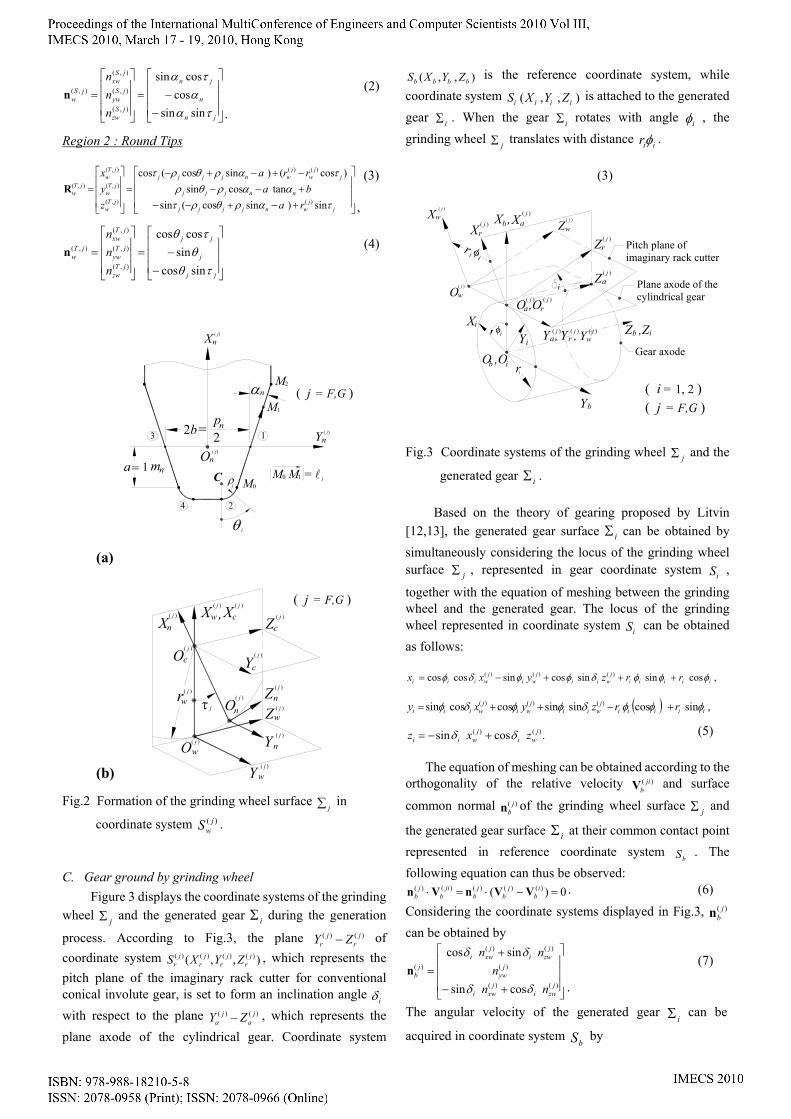
B. Mathematical model of grinding wheel The axial section of the grinding wheel jΣ illustrated
in Fig.2(a) contains four major regions: two straight-edges (regions 1 and 3) and two round tips (regions 2 and 4). Regions 1 and 3 generate the working tooth surfaces, while regions 2 and 4 generate the fillets of the gear. Herein,
nα denotes the normal pressure angle, jρ denotes the radius
of fillet, while nm and np represent the normal module and circular pitch, respectively. Owing to the symmetry, only the right side of the grinding wheel (i.e. regions 1 and 2) is considered in the following derivation. According to the coordinate system illustrated in Fig.2(b), the grinding wheel surface can be traced out in coordinate system
),,( )()()()( jw
jw
jw
jw ZYXS by rotating the above-mentioned axial
section, which is attached to plane )()( jn
jn YX − , by an angle jτ
along a circular arc with radius )( jwr and center at )( j
cO , with
respect to the )( jcY -axis. Herein, )( j
wr represents the pitch radius of the grinding wheel. The surfaces and unit normals of the straight edges and the round tips on the grinding wheel
jΣ can be obtained in coordinate system )( jwS as follows:
Region 1 : Straight Edges
⎥⎥⎥
⎦
⎤
⎢⎢⎢
⎣
⎡
+−−+−
−+−=
⎥⎥⎥
⎦
⎤
⎢⎢⎢
⎣
⎡
=
jj
wnjj
nnj
jj
wj
wnjj
jSw
jSw
jSw
jSw
rabarra
zyx
ταταα
τατ
sin)cos(sintansin
)cos()cos(cos
)(
)()(
),(
),(
),(
),(
l
l
l
R
,
(1)
⎥⎥⎥
⎦
⎤
⎢⎢⎢
⎣
⎡
−−=
⎥⎥⎥
⎦
⎤
⎢⎢⎢
⎣
⎡
=
jn
n
jn
jSzw
jSyw
jSxw
jSw
nnn
ταα
τα
sinsincos
cossin
),(
),(
),(
),(n.
(2)
Region 2 : Round Tips
⎥⎥⎥
⎦
⎤
⎢⎢⎢
⎣
⎡
+−+−−+−−−+−+−
=⎥⎥⎥
⎦
⎤
⎢⎢⎢
⎣
⎡
=
jj
wnjjjj
nnjjj
jj
wj
wnjjjj
jTw
jTw
jTw
jTw
rabarra
zyx
ταρθρτααρθρ
ταρθρτ
sin)sincos(sintancossin
)cos()sincos(cos
)(
)()(
),(
),(
),(
),(R
,
(3) (3)
⎥⎥⎥
⎦
⎤
⎢⎢⎢
⎣
⎡
−−=
⎥⎥⎥
⎦
⎤
⎢⎢⎢
⎣
⎡
=
jj
j
jj
jTzw
jTyw
jTxw
jTw
nnn
τθθ
τθ
sincossin
coscos
),(
),(
),(
),(n (4)
(a)
(b)
2b = p n2
a m n1
M1
M0
=
2M
θ
α
ρ
2
1
( j = F,G )
( j)
( j)
j
3
4
COn
Yn
( j)Xn
M0 M1 = l
n
j
( j )
O nZτw r
Ow( j )
j
Yw( j )
Z
Y
n
n( j )
w( j )
X
( j )
( j )
Oc
nX( j ) ,
( j )
Xw
cY( j )
( j )
Z( j )
cc( j )
( j = F,G )
j
Fig.2 Formation of the grinding wheel surface
j∑ in
coordinate system )( jwS .
C. Gear ground by grinding wheel Figure 3 displays the coordinate systems of the grinding
wheel jΣ and the generated gear iΣ during the generation
process. According to Fig.3, the plane )()( jr
jr ZY − of
coordinate system ),,( )()()()( jr
jr
jr
jr ZYXS , which represents the
pitch plane of the imaginary rack cutter for conventional conical involute gear, is set to form an inclination angle iδ with respect to the plane )()( j
aj
a ZY − , which represents the plane axode of the cylindrical gear. Coordinate system
),,( bbbb ZYXS is the reference coordinate system, while coordinate system ),,( iiii ZYXS is attached to the generated gear iΣ . When the gear iΣ rotates with angle iφ , the grinding wheel jΣ translates with distance iirφ .
φi
ri
Y , Y ,raYi
O ,Oa r
Z ,Zib
Za
rZ
Xi
O ,Ob i
rXXX ,b a
Y b
( j )
( j )
( j )
( j )
( j )( j )
( j ) ( j )
Pitch plane of imaginary rack cutter
Plane axode of the cylindrical gear
Gear axode
( j = F,G )( i = 1, 2 )
i
wX ( j )
φiir
Ow( j )
Yw( j )
( j )
Z w
Fig.3 Coordinate systems of the grinding wheel jΣ and the
generated gear iΣ .
Based on the theory of gearing proposed by Litvin [12,13], the generated gear surface iΣ can be obtained by simultaneously considering the locus of the grinding wheel surface jΣ , represented in gear coordinate system iS ,
together with the equation of meshing between the grinding wheel and the generated gear. The locus of the grinding wheel represented in coordinate system iS can be obtained as follows:
,cossinsincossincoscos )()()(iiiii
jwii
jwi
jwiii rrzyxx φφφδφφδφ +++−=
( ) ,sincossinsincoscossin )()()(iiiii
jwii
jwi
jwiii rrzyxy φφφδφφδφ +−++=
.cossin )()( jwi
jwii zxz δδ +−= (5)
The equation of meshing can be obtained according to the
orthogonality of the relative velocity )( jibV and surface
common normal )( jbn of the grinding wheel surface jΣ and
the generated gear surface iΣ at their common contact point represented in reference coordinate system
bS . The following equation can thus be observed:
0)( )()()()()( =−⋅=⋅ ib
jb
jb
jib
jb VVnVn . (6)
Considering the coordinate systems displayed in Fig.3, )( jbn
can be obtained by
⎥⎥⎥
⎦
⎤
⎢⎢⎢
⎣
⎡
+−
+=
)()(
)(
)()(
)(
cossin
sincos
jzwi
jxwi
jyw
jzwi
jxwi
jb
nnn
nn
δδ
δδn
.
(7)
The angular velocity of the generated gear iΣ can be
acquired in coordinate system bS by
⎥⎥⎥
⎦
⎤
⎢⎢⎢
⎣
⎡
−==
i
iib dt
d
ω
φ 00
)(ω.
(8)
Furthermore, the velocities of the grinding wheel surface jΣ
and the generated gear surface iΣ at their common contact point can be expressed by )( j
bV and )(ibV , respectively, as
follows:
⎥⎥⎥
⎦
⎤
⎢⎢⎢
⎣
⎡−=
i
iij
b r0
0)( ωV
,
(9)
and
⎥⎥⎥
⎦
⎤
⎢⎢⎢
⎣
⎡
−−−−
=×=0sincos )()(
)(
)()()(i
jwi
jwi
iij
w
ij
bi
bi
b rzxry
δδφ
ωRωV (10)
Substituting Eqs. (7), (9) and (10) into Eq.(6) enables us to solve the equation of meshing. The tooth surface of the generated gear iΣ can be expressed by Eqs.(5) and (6). Hence, the complete mathematical models of concave conical involute gear including the working tooth surfaces and fillets have been derived.
III. FINITE ELEMENT CONTACT STRESS ANALYSIS In this study, a single pair of contact teeth is constructed
to perform the stress analysis. Application of FE contact stress analysis requires the development of the FE model formed by FE meshes, the definition of contacting surfaces, the specification of surface interaction model, and the establishment of boundary conditions. The following assumptions have been made: (1) the stress is in the elastic range of the material; (2) the material is isotropic; and (3) heat generation and thermal stress are ignored.
A. Finite element model The three-dimensional linear brick solid element,
C3D8 [14], having eight nodes and six faces, is employed to discretize the geometric models of the pinion and the gear tooth surfaces. A mesh-generation program has been developed to divide the gear tooth into elements as well as to generate nodal points. The developed mesh-generation program allows the mesh density and the number of elements to be adjusted to meet specific requirements. Nodes of the FE model lying on the tooth surfaces are guaranteed to be points of the real tooth surfaces of the pinion and the gear. Therefore, the lost of accuracy due to the development of FE model using CAD computer programs is avoided. In general, an FE model with a larger number of elements may lead to more accurate results. However, increasing the mesh densities for the whole FE model is not necessary from the computational viewpoint, especially considering the limit of computer memories and the computational efficiency. Therefore, we use a very dense mesh in the possible contact regions to ensure the accuracy of FEA, and a coarse mesh in the rest of the teeth to reduce the computation time needed.
B. Surface definition and interaction properties One of the ABAQUS advantages in comparison with
other FEA programs is that the ABAQUS can generate the contact elements automatically after the user appropriately defines the contact pair of surfaces as the master and slave ones. Generally, the master surface should be chosen as the surface of the stiffer body or as the surface with the coarser mesh if the two surfaces are with comparable stiffness. During the analysis processes, the nodes of the master surface can penetrate into the slave surface; however, the nodes on slave surfaces are constrained not to penetrate into the master surface. In this study, the tooth surface of the gear 2Σ has been chosen as the master surface, while the tooth surface of the pinion 1Σ is considered as the slave surface. Two options, “small sliding” and “no friction”, should be specified to define the interaction between the contact pair. Meanwhile, the friction coefficient is given as zero by assuming that the gears are meshed under good lubrication conditions.
C. Boundary conditions For the linear brick C3D8 element, each node has three
degree-of-freedom (DOF), i.e., translations in the nodal x-, y- and z- directions. In this study, all the three DOFs of the nodes located on the two lateral sides of the base of the gear 2Σ are assumed fixed. On the other hand, rigid beam elements are applied to connect the nodes on the bottom of the base of the pinion 1Σ with those on the pinion’s rotational axis. In addition, the nodes on the pinion’s rotational axis are constrained in a way such that the pinion 1Σ can rotate about its rotational axis only. Consequently, the gear 2Σ is statically fixed and a torque of 200 N-m is applied directly to the remaining DOF at the pinion’s rotational axis to make the tooth surfaces of the pinion 1Σ and gear 2Σ contact with each other.
IV. SIMULATION RESULTS AND DISCUSSIONS In this study, the gear pair is composed of a straight
conical involute pinion and gear mounted with an intersected angle of o10 . The major design parameters for the gear pairs in the following examples are listed in Table 1. Meanwhile, the medium carbon steel AISI 1045 with the material properties listed in Table 2 has been chosen for the gear material for the FEA.
Table 1 Major design parameters of the gear pairs
Pinion 1Σ Gear 2Σ
Number of teeth 2521 == NN
Face width mmWW 4021 ==
Normal pressure angle
o20=nα Normal module teethmmmn /4=
Intersected angle o10
Table 2 Material properties of AISI 1045
Young’s Modulus 205 GPa Poisson’s Ratio 0.292
Allowable Contact Stress [15] 980 MPa
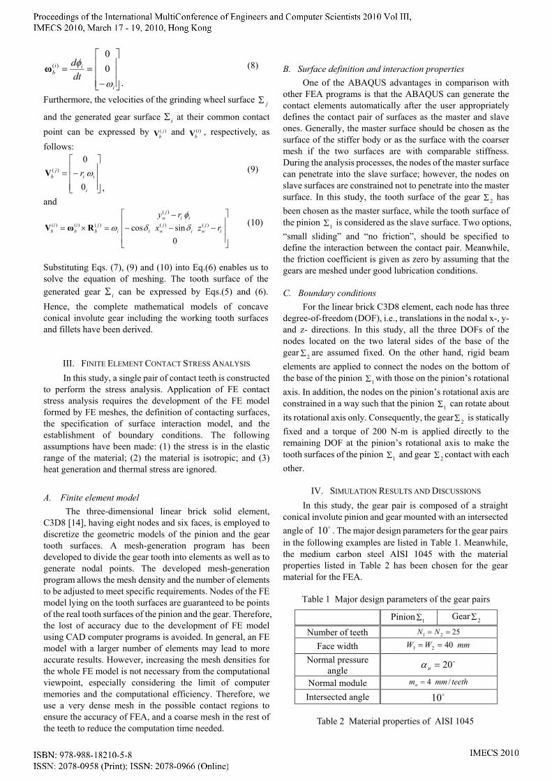
Example 1: Conventional conical involute gear pairs with different assembly of 1δ and 2δ
In this example, we let the pitch radii of the grinding wheels approach to infinity (i.e. ∞== )()( G
wF
w rr ) to make the concave conical involute gear identical to the conventional conical involute gear which generated by the imaginary rack cutter. With the same intersected angle of o10 , three models of conical involute gear pairs with different assembly of 1δ and 2δ are listed in Fig.4.
(a) Model A ( °= 01δ , °= 102δ )
(b) Model B ( °= 5.21δ , °= 5.72δ )
(c) Model C ( °= 51δ , °= 52δ )
Fig.4 Three models of conical involute gear pairs with different assembly of 1δ and 2δ .
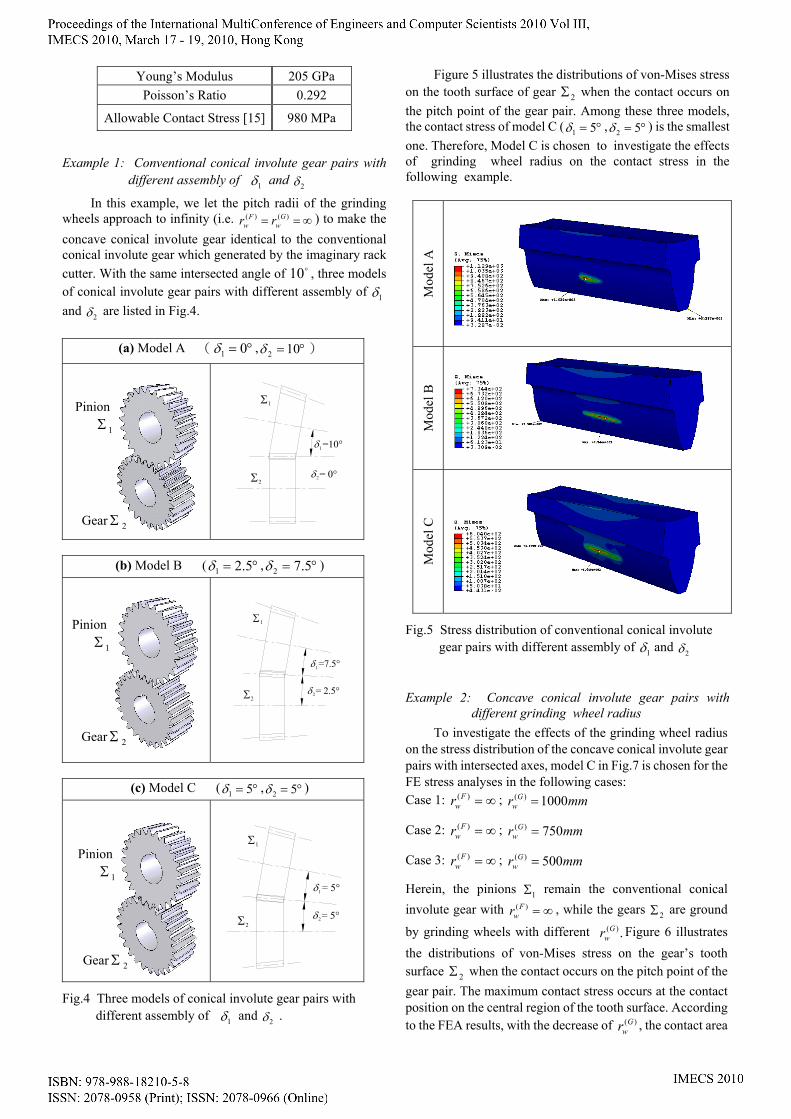
Figure 5 illustrates the distributions of von-Mises stress on the tooth surface of gear 2Σ when the contact occurs on the pitch point of the gear pair. Among these three models, the contact stress of model C ( °= 51δ , °= 52δ ) is the smallest one. Therefore, Model C is chosen to investigate the effects of grinding wheel radius on the contact stress in the following example.
Mod
el A
Mod
el B
Mod
el C
Fig.5 Stress distribution of conventional conical involute gear pairs with different assembly of 1δ and 2δ
Example 2: Concave conical involute gear pairs with different grinding wheel radius
To investigate the effects of the grinding wheel radius on the stress distribution of the concave conical involute gear pairs with intersected axes, model C in Fig.7 is chosen for the FE stress analyses in the following cases: Case 1: ∞=)(F
wr ; mmr Gw 1000)( =
Case 2: ∞=)(Fwr ; mmr G
w 750)( =
Case 3: ∞=)(Fwr ; mmr G
w 500)( =
Herein, the pinions 1Σ remain the conventional conical involute gear with ∞=)(F
wr , while the gears 2Σ are ground
by grinding wheels with different .)(Gwr Figure 6 illustrates
the distributions of von-Mises stress on the gear’s tooth surface 2Σ when the contact occurs on the pitch point of the gear pair. The maximum contact stress occurs at the contact position on the central region of the tooth surface. According to the FEA results, with the decrease of )(G
wr , the contact area
Pinion
1Σ
Gear 2Σ
Pinion
1Σ
Pinion
1Σ
Gear 2Σ
Gear 2Σ
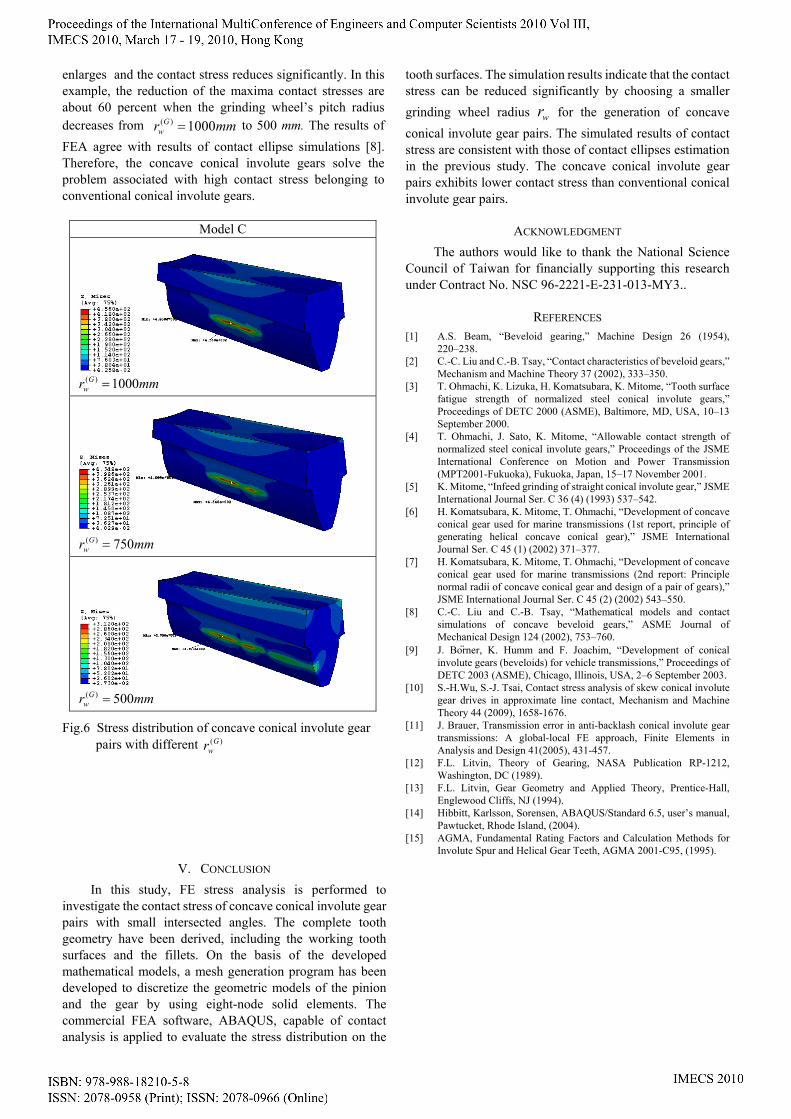
enlarges and the contact stress reduces significantly. In this example, the reduction of the maxima contact stresses are about 60 percent when the grinding wheel’s pitch radius decreases from mmr G
w 1000)( = to 500 mm. The results of FEA agree with results of contact ellipse simulations [8]. Therefore, the concave conical involute gears solve the problem associated with high contact stress belonging to conventional conical involute gears.
Model C
mmr G
w 1000)( =
mmr G
w 750)( =
mmr G
w 500)( =
Fig.6 Stress distribution of concave conical involute gear pairs with different )(G
wr
V. CONCLUSION In this study, FE stress analysis is performed to
investigate the contact stress of concave conical involute gear pairs with small intersected angles. The complete tooth geometry have been derived, including the working tooth surfaces and the fillets. On the basis of the developed mathematical models, a mesh generation program has been developed to discretize the geometric models of the pinion and the gear by using eight-node solid elements. The commercial FEA software, ABAQUS, capable of contact analysis is applied to evaluate the stress distribution on the
tooth surfaces. The simulation results indicate that the contact stress can be reduced significantly by choosing a smaller grinding wheel radius wr for the generation of concave conical involute gear pairs. The simulated results of contact stress are consistent with those of contact ellipses estimation in the previous study. The concave conical involute gear pairs exhibits lower contact stress than conventional conical involute gear pairs.
ACKNOWLEDGMENT The authors would like to thank the National Science
Council of Taiwan for financially supporting this research under Contract No. NSC 96-2221-E-231-013-MY3..
REFERENCES [1] A.S. Beam, “Beveloid gearing,” Machine Design 26 (1954),
220–238. [2] C.-C. Liu and C.-B. Tsay, “Contact characteristics of beveloid gears,”
Mechanism and Machine Theory 37 (2002), 333–350. [3] T. Ohmachi, K. Lizuka, H. Komatsubara, K. Mitome, “Tooth surface
fatigue strength of normalized steel conical involute gears,” Proceedings of DETC 2000 (ASME), Baltimore, MD, USA, 10–13 September 2000.
[4] T. Ohmachi, J. Sato, K. Mitome, “Allowable contact strength of normalized steel conical involute gears,” Proceedings of the JSME International Conference on Motion and Power Transmission (MPT2001-Fukuoka), Fukuoka, Japan, 15–17 November 2001.
[5] K. Mitome, “Infeed grinding of straight conical involute gear,” JSME International Journal Ser. C 36 (4) (1993) 537–542.
[6] H. Komatsubara, K. Mitome, T. Ohmachi, “Development of concave conical gear used for marine transmissions (1st report, principle of generating helical concave conical gear),” JSME International Journal Ser. C 45 (1) (2002) 371–377.
[7] H. Komatsubara, K. Mitome, T. Ohmachi, “Development of concave conical gear used for marine transmissions (2nd report: Principle normal radii of concave conical gear and design of a pair of gears),” JSME International Journal Ser. C 45 (2) (2002) 543–550.
[8] C.-C. Liu and C.-B. Tsay, “Mathematical models and contact simulations of concave beveloid gears,” ASME Journal of Mechanical Design 124 (2002), 753–760.
[9] J. Bo ̈rner, K. Humm and F. Joachim, “Development of conical involute gears (beveloids) for vehicle transmissions,” Proceedings of DETC 2003 (ASME), Chicago, Illinois, USA, 2–6 September 2003.
[10] S.-H.Wu, S.-J. Tsai, Contact stress analysis of skew conical involute gear drives in approximate line contact, Mechanism and Machine Theory 44 (2009), 1658-1676.
[11] J. Brauer, Transmission error in anti-backlash conical involute gear transmissions: A global-local FE approach, Finite Elements in Analysis and Design 41(2005), 431-457.
[12] F.L. Litvin, Theory of Gearing, NASA Publication RP-1212, Washington, DC (1989).
[13] F.L. Litvin, Gear Geometry and Applied Theory, Prentice-Hall, Englewood Cliffs, NJ (1994).
[14] Hibbitt, Karlsson, Sorensen, ABAQUS/Standard 6.5, user’s manual, Pawtucket, Rhode Island, (2004).
[15] AGMA, Fundamental Rating Factors and Calculation Methods for Involute Spur and Helical Gear Teeth, AGMA 2001-C95, (1995).