Embed Size (px)
Citation preview
1 Construction, Working and Maintenance of Equipments for Unloading Bulk Materials www.practicalmaintenance.net
Construction, Working and Maintenance of
Equipments for Unloading Bulk Materials
By K. P. Shah
Email: kpshah123[at]gmail.com (Please replace [at] with @) Committed to improve the Quality of Life
For more articles on mechanical maintenance, visit www.practicalmaintenance.net
The information contained in this booklet represents a significant collection of technical information about construction, working and maintenance of equipments/systems (wagon tippling systems, track hopper systems, ship unloaders and truck unloaders) for unloading bulk materials. This information will help to achieve increased reliability at a decreased cost. Assemblage of this information will provide a single point of reference that might otherwise be time consuming to obtain. Most of information given in this booklet is mainly derived from literature on the subject from sources as per the reference list given at the end of this booklet. For more information, please refer them. All information contained in this booklet has been assembled with great care. However, the information is given for guidance purposes only. The ultimate responsibility for its use and any subsequent liability rests with the end user. Please view the disclaimer uploaded on http://www.practicalmaintenance.net.
(Edition: January 2019)

2 Construction, Working and Maintenance of Equipments for Unloading Bulk Materials www.practicalmaintenance.net
Content
Chapter Title Page No.
1 Need for Unloading Equipments 3
2 Wagon Tippling Systems 4
3 Track Hopper Systems 15
4 Ship Unloaders 19
5 Truck Unloaders 23
- References 26

3 Construction, Working and Maintenance of Equipments for Unloading Bulk Materials www.practicalmaintenance.net
Need for Unloading Equipments Most of the time bulk material is received by process plants by railway, ship / barge or truck. As the quantity of the material received is huge, it needs mechanized means for unloading it. In case of material received from the mines / ports by the railway wagons, the wagon unloading system is required. Two types of wagons are generally used in the Indian industry viz. BOXN wagons and BOBRN wagons. In case of BOXN wagons, the material is discharged from the top while in the case of BOBRN wagons, it is discharged from the bottom. Hence two different types of wagon unloading systems/equipments are adopted for unloading the material from these wagons. A system consisting of wagon tipplers is used for BOXN type wagons whereas unloading system for BOBRN wagons consists of track hopper below the rail track. In view of this, information on construction, working and maintenance of wagon tippling system, track hopper system, ship unloaders and truck unloaders is given in this booklet.

4 Construction, Working and Maintenance of Equipments for Unloading Bulk Materials www.practicalmaintenance.net
Wagon Tippling Systems The wagon tippling system is designed to unload materials like coal, ore, limestone, etc. from the open type railway wagons. It consists of a wagon tippler, the wagon positioning equipment, underground hopper (RCC type with suitable liner or structural steel fabricated type), and feeder below the hopper for evacuating the material unloaded into the hopper. The existing population of open type wagons in the Indian Railways consists of BOY, BOX, BOXN and BOXNHA wagons of which BOXN wagons form the bulk. However, new types of open wagons like BOY25, BOXNLW, BOXNHL and BOXN25 are being introduced in the Indian Railways. New designs for open wagons for coal and iron ore for DFC & Feeder routes (DFC25 and DFC32.5) are also under consideration. The wagon tippler consists of a table for positioning the wagon, wagon holding mechanism, gears and pinions for rotation, drive unit, etc. If specified by the purchaser, integrated weigh bridge, load cell type or mechanical type, conforming to relevant standard is provided on the tippler table to weigh the gross and tare weight of wagons which are being handled. There may also be a provision to record gross load, tare load, date and number of wagons. Generally, tipplers are provided with side arm charger for positioning of wagons on the tippler. The tipplers can be of side discharge (rotaside) type or rotary type. There are two types of rotary wagon tipplers: C-type and O-type.
Side Discharge (Rotaside) Wagon Tippler
Above figure shows photograph of a typical side discharge (rotaside) wagon tippler.
5 Construction, Working and Maintenance of Equipments for Unloading Bulk Materials www.practicalmaintenance.net
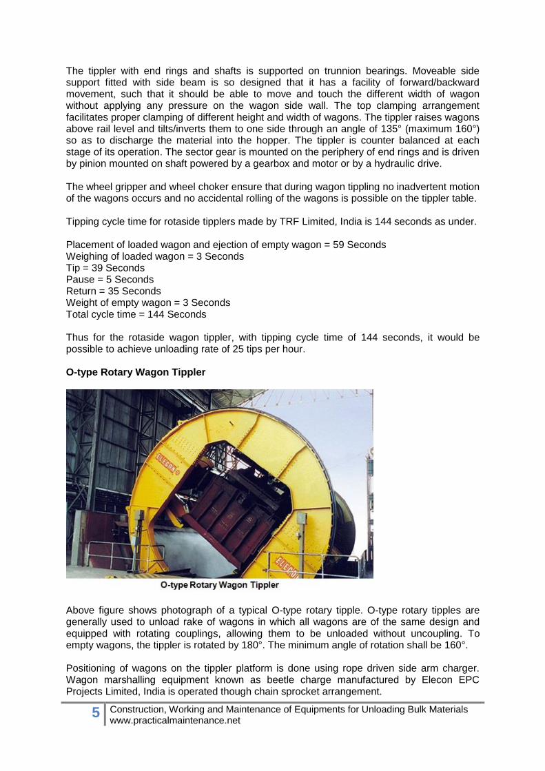
The tippler with end rings and shafts is supported on trunnion bearings. Moveable side support fitted with side beam is so designed that it has a facility of forward/backward movement, such that it should be able to move and touch the different width of wagon without applying any pressure on the wagon side wall. The top clamping arrangement facilitates proper clamping of different height and width of wagons. The tippler raises wagons above rail level and tilts/inverts them to one side through an angle of 135° (maximum 160°) so as to discharge the material into the hopper. The tippler is counter balanced at each stage of its operation. The sector gear is mounted on the periphery of end rings and is driven by pinion mounted on shaft powered by a gearbox and motor or by a hydraulic drive. The wheel gripper and wheel choker ensure that during wagon tippling no inadvertent motion of the wagons occurs and no accidental rolling of the wagons is possible on the tippler table. Tipping cycle time for rotaside tipplers made by TRF Limited, India is 144 seconds as under. Placement of loaded wagon and ejection of empty wagon = 59 Seconds Weighing of loaded wagon = 3 Seconds Tip = 39 Seconds Pause = 5 Seconds Return = 35 Seconds Weight of empty wagon = 3 Seconds Total cycle time = 144 Seconds Thus for the rotaside wagon tippler, with tipping cycle time of 144 seconds, it would be possible to achieve unloading rate of 25 tips per hour. O-type Rotary Wagon Tippler
Above figure shows photograph of a typical O-type rotary tipple. O-type rotary tipples are generally used to unload rake of wagons in which all wagons are of the same design and equipped with rotating couplings, allowing them to be unloaded without uncoupling. To empty wagons, the tippler is rotated by 180°. The minimum angle of rotation shall be 160°. Positioning of wagons on the tippler platform is done using rope driven side arm charger. Wagon marshalling equipment known as beetle charge manufactured by Elecon EPC Projects Limited, India is operated though chain sprocket arrangement.
6 Construction, Working and Maintenance of Equipments for Unloading Bulk Materials www.practicalmaintenance.net
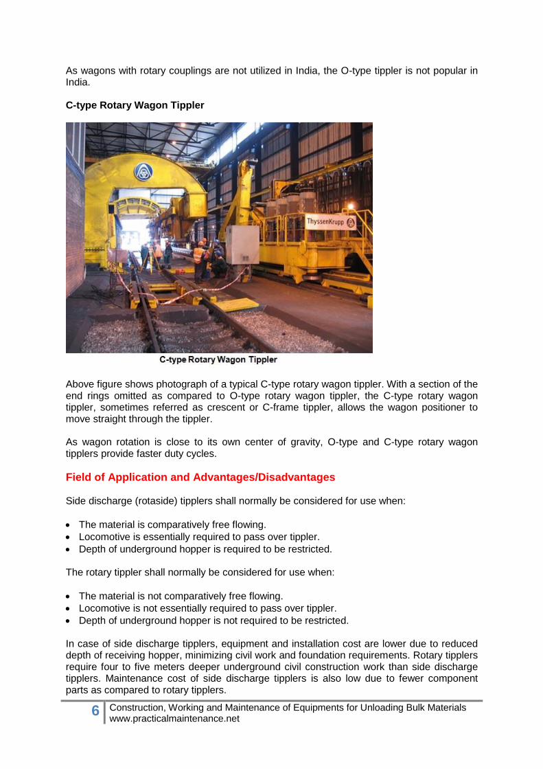
As wagons with rotary couplings are not utilized in India, the O-type tippler is not popular in India. C-type Rotary Wagon Tippler
Above figure shows photograph of a typical C-type rotary wagon tippler. With a section of the end rings omitted as compared to O-type rotary wagon tippler, the C-type rotary wagon tippler, sometimes referred as crescent or C-frame tippler, allows the wagon positioner to move straight through the tippler. As wagon rotation is close to its own center of gravity, O-type and C-type rotary wagon tipplers provide faster duty cycles.
Field of Application and Advantages/Disadvantages Side discharge (rotaside) tipplers shall normally be considered for use when:
The material is comparatively free flowing.
Locomotive is essentially required to pass over tippler.
Depth of underground hopper is required to be restricted. The rotary tippler shall normally be considered for use when:
The material is not comparatively free flowing.
Locomotive is not essentially required to pass over tippler.
Depth of underground hopper is not required to be restricted. In case of side discharge tipplers, equipment and installation cost are lower due to reduced depth of receiving hopper, minimizing civil work and foundation requirements. Rotary tipplers require four to five meters deeper underground civil construction work than side discharge tipplers. Maintenance cost of side discharge tipplers is also low due to fewer component parts as compared to rotary tipplers.

7 Construction, Working and Maintenance of Equipments for Unloading Bulk Materials www.practicalmaintenance.net
However, the energy requirement of side discharge tipplers is much higher due to the lifting the wagon while unloading. They also require heavy counterweights to even out the mechanical effort. In contrast, as rotary tipplers rotate the wagons about their center of gravity, no counterweights are required and hence they are energy efficient. Rotary tipplers also provide faster duty cycles as compared to side discharge tipplers.
Side Arm Charger There are different types of wagon positioning equipment like side arm charger, beetle charger and shunting locos. The side arm chargers are being used in most of the plants in India as this equipment is much faster compared to the others.
Above figure shows a side arm charger. Side arm charger is a marshalling device to position the loaded wagon centrally on tippler platform one by one for unloading operation by wagon tippler. Side arm charger is a rail mounted machine used to pull the loaded wagon along with the rake and push out the empty wagon from the tippler platform after tippling. The tractive force of the side arm charger shall be suitable for hauling (moving) one fully loaded rake (58 wagons). Generally, it’s operating/hauling speed is 0.5 m/s. Operation The full rake of 58 wagons is brought in by locomotive and stopped with the first wagon within range of the side arm charger. The locomotive is then taken away. The charger is driven towards the first wagon, its arm is lowered and it is coupled to the first wagon of the rake. The charger then hauls the rake forward by one wagon length and stopped. Here the first wagon is decoupled from the rake. The charger then propels the first wagon on to the tippler table centrally, gets decoupled and clears off the tippler. Now the wagon tippler is ready for operation. In the meanwhile, the side arm charger moves back to initial position for next cycle. In the next cycle, the rake is drawn up by the one wagon length, and the previously tippled wagon is ejected simultaneously. The side arm charger is run on a separate pair of rails which runs parallel to wagon tippler rail. Approximate travel length of the charger is 33 meters. Side arm charger’s movement on the rail is actuated by the rack and pinion arrangement. The pinions are driven by hydraulic motors. The hydraulic motors are driven from hydraulic pressure and the hydraulic pressure is generated from a hydraulic power pack (maximum pressure = 180 bars).
8 Construction, Working and Maintenance of Equipments for Unloading Bulk Materials www.practicalmaintenance.net
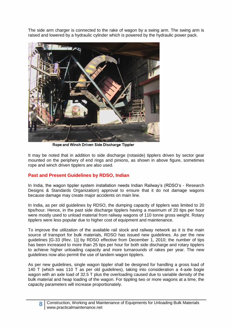
The side arm charger is connected to the rake of wagon by a swing arm. The swing arm is raised and lowered by a hydraulic cylinder which is powered by the hydraulic power pack.
It may be noted that in addition to side discharge (rotaside) tipplers driven by sector gear mounted on the periphery of end rings and pinions, as shown in above figure, sometimes rope and winch driven tipplers are also used.
Past and Present Guidelines by RDSO, Indian In India, the wagon tippler system installation needs Indian Railway’s (RDSO’s - Research Designs & Standards Organization) approval to ensure that it do not damage wagons because damage may create major accidents on main line. In India, as per old guidelines by RDSO, the dumping capacity of tipplers was limited to 20 tips/hour. Hence, in the past side discharge tipplers having a maximum of 20 tips per hour were mostly used to unload material from railway wagons of 110 tonne gross weight. Rotary tipplers were less popular due to higher cost of equipment and maintenance. To improve the utilization of the available rail stock and railway network as it is the main source of transport for bulk materials, RDSO has issued new guidelines. As per the new guidelines [G-33 (Rev. 1)] by RDSO effective from December 1, 2010; the number of tips has been increased to more than 25 tips per hour for both side discharge and rotary tipplers to achieve higher unloading capacity and more turnarounds of rakes per year. The new guidelines now also permit the use of tandem wagon tipplers. As per new guidelines, single wagon tippler shall be designed for handling a gross load of 140 T (which was 110 T as per old guidelines), taking into consideration a 4-axle bogie wagon with an axle load of 32.5 T plus the overloading caused due to variable density of the bulk material and heap loading of the wagon. For tippling two or more wagons at a time, the capacity parameters will increase proportionately.

9 Construction, Working and Maintenance of Equipments for Unloading Bulk Materials www.practicalmaintenance.net
As Indian Railway has started charging for the wagons based on revised wagon carrying capacity, companies having wagon tipplers as per old designs (gross weight of 110 T) have started upgrading capacity of their wagon tipplers. Since free time for unloading a rake is also reduced, companies have started preferring rotary tipplers as well as tandem tipplers to avid demurrage charges.
Above figure shows photograph of a C-type rotary tandem wagon tippler under construction.
RDSO’s Guidelines [as per G-33 (Rev. 1)] In India, wagon tipplers are designed as per IS 10095 and RDSO’s guidelines. RDSO’s guidelines also give the basic requirements to be met for obtaining RDSO's approval for installation. Important points of RDSO’s guidelines as per G-33 (Rev. 1) are as under. Design Parameters Single wagon tippler shall be designed for handling a gross load of 140 T. For tippling two or more wagons at a time, the capacity parameters will increase proportionately. Where a locomotive (diesel loco) is required to pass over or stand on the tippler, the tippler shall be able to bear the load of the locomotive without sustaining any permanent deformation (tippler shall be suitable for accepting locomotives weighing up to 140 T, at a speed of 8 kmph). For electric loco, a bypass track to be provided parallel to the wagon tippler. General Requirements The design and construction of components of tipplers and auxiliary handling equipment coming into contact with any part of wagon shall be such that no damage whatsoever is caused to the wagon equipment or its paint.
10 Construction, Working and Maintenance of Equipments for Unloading Bulk Materials www.practicalmaintenance.net
The side support beam shall be moveable type; the movement being done by hydraulic arrangement. Facility of forward / backward movement should exist, such that it should be able to move and touch the wagon without applying any pressure on the wagon side-wall. Movement of the side support should be controlled and the speed should be crawling just before making contact with the wagon sidewall. There shall be metal to metal contact between the side support beam and the side stanchions of the wagon. The top clamping of the wagon shall be done through hydraulically locked top clamps. Top clamps should engage when the wagon tilts by more than 15 degrees. Top clamp locks should include a wagon bogie spring relief mechanism for permitting release of bogie springs. Top clamps should exert the bare minimum pressure on the top coping of the wagon, so as to just keep it in position. The top clamping arrangement shall be of longitudinal / transverse type and provided with self-aligning feature. The transverse type top clamping shall have 6 transverse top clamping beams i.e. the bearing face of the beam shall contact the top of the wagon at 12 locations (six on each side). The longitudinal type top clamping shall be such that the clamping pads cover the full length of wagon top coping. Each bearing face shall contact the top of the wagon over a width of not less than 250 mm and shall be provided with rubber pads or suitable alternative not less than 50 mm thick. The shore hardness of the rubber pad should not be less than 70A. Devices shall be built-in for spotting of wagons on the tippler table, so as to discharge the material in hoppers. Safety Requirements
The design of the tippler shall avoid, as far as possible, any spillage of the material handled by the wagons.
Devices shall be built-in to prevent any over run of the wagons in either direction.
Automatic devices shall be provided to hold the tipplers securely in any position in the event of failure of the drive unit.
All tipplers shall have means to limit the angle of tippling.
Arrangement shall be made on tipplers to prevent feet being trapped between the platform and the base of the tippler.
A device shall be provided to prevent an empty wagon from being released until the tippler is back in original position.
A device shall be provided to prevent the entry of a non-scheduled wagon into a tippler.
Fully integrated controls should be provided for wagon positioning system, wagon holding devices and wagon tippler. The controls should be interlocked so that there is no chance of accident due to error in sequence of operation.
All tippler installations shall be marked permanently and legibly in a clearly visible place, with the following information:
Maximum capacity of the wagons and the type of wagons to be tippled.
11 Construction, Working and Maintenance of Equipments for Unloading Bulk Materials www.practicalmaintenance.net
If locomotives are required to run over the tippler, the maximum permissible mass, maximum permissible axle loading and speed.
Maximum speed of the wagon passing through the tippler.
An instruction forbidding the tippler to be operated as long as the wagon is not held on the platform in its tippling position. This instruction shall also state that the tippler shall be held in appropriate position before an attempt is made to remove the empty wagon.
The emergency stop controls shall be provided adjacent to the wagon tipplers in the readily accessible positions. The outhaul side track should satisfy the following conditions:
The gradient of the outhaul track should not exceed “1 in 1200”.
The length of the outhaul track, with the specified gradient, is not less than 650 m for full rake tippling.
For partial rake tippling (not less than the half rake), proportionate track length (equal to the half the rake length or more) with track gradient not exceeding "1 in 1200" will be permitted.
In case of limitation of adequate track length on the outhaul side, as specified above, the user can consider use of transfer platform for shifting the empty wagons, on a parallel track. This parallel track shall satisfy the same conditions of gradient as listed out above.
No person, other than a qualified and competent person so authorized shall operate the tippler. Positioning System for Wagon Wagon tipplers shall be provided with side arm charger for positioning of wagons on the tipplers such that:
Side arm charger should be of sufficient capacity with some positive system for centering of wagon on the tippler table.
Drive unit for the side arm charger should be of positive type e.g. rack and pinion, so that sudden jerks/slippages are avoided. Suitable technology should be used, so that the wagon can be moved at slow speeds for placement on tippler table.
Charger should be able to slow down to creeping speed just before the final positioning Wagon and Train Holding Devices Wheel grippers are mandatory and should be located on the tippler table to prevent inadvertent motion of the wagons during tippling operation. Wheel grippers should be made of soft material and should be free from serrations or any such provision on its holding face. Retractable wheel chocks are mandatory and should be fitted at the in-haul & out -haul tracks, to prevent accidental rolling of the wagons on the tippler table. Requirements / Conditions for RDSO's Approval The tippler shall have the capacity to tip at least 25 wagons per hour i.e. 25 tips per hour, with suitable provisions so that the wagon is not damaged in the tippling process. If the client desires lesser numbers of tips, concurrence of the concerned railway shall be obtained. It shall entirely be the responsibility of the owner for ensuring that no damage whatsoever is caused to the wagons during handling on the tippler. The owner shall guarantee to pay to the Railway the rectification charges in case of any damage to the wagons.
12 Construction, Working and Maintenance of Equipments for Unloading Bulk Materials www.practicalmaintenance.net
The approval for operation of tippler is subject to withdrawal at any time in event of owner's failure to ensure handling of wagons without damage.
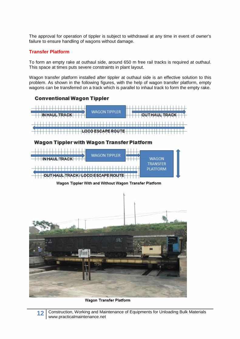
Transfer Platform To form an empty rake at outhaul side, around 650 m free rail tracks is required at outhaul. This space at times puts severe constraints in plant layout. Wagon transfer platform installed after tippler at outhaul side is an effective solution to this problem. As shown in the following figures, with the help of wagon transfer platform, empty wagons can be transferred on a track which is parallel to inhaul track to form the empty rake.
13 Construction, Working and Maintenance of Equipments for Unloading Bulk Materials www.practicalmaintenance.net
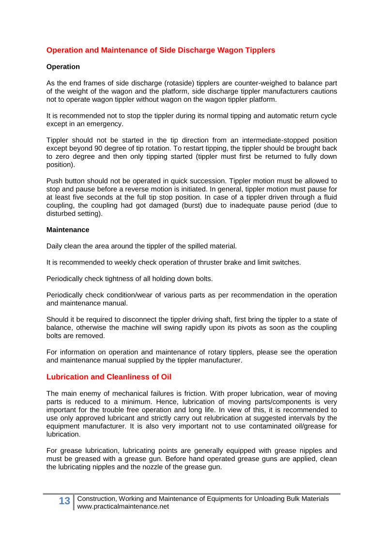
Operation and Maintenance of Side Discharge Wagon Tipplers Operation As the end frames of side discharge (rotaside) tipplers are counter-weighed to balance part of the weight of the wagon and the platform, side discharge tippler manufacturers cautions not to operate wagon tippler without wagon on the wagon tippler platform. It is recommended not to stop the tippler during its normal tipping and automatic return cycle except in an emergency. Tippler should not be started in the tip direction from an intermediate-stopped position except beyond 90 degree of tip rotation. To restart tipping, the tippler should be brought back to zero degree and then only tipping started (tippler must first be returned to fully down position). Push button should not be operated in quick succession. Tippler motion must be allowed to stop and pause before a reverse motion is initiated. In general, tippler motion must pause for at least five seconds at the full tip stop position. In case of a tippler driven through a fluid coupling, the coupling had got damaged (burst) due to inadequate pause period (due to disturbed setting). Maintenance Daily clean the area around the tippler of the spilled material. It is recommended to weekly check operation of thruster brake and limit switches. Periodically check tightness of all holding down bolts. Periodically check condition/wear of various parts as per recommendation in the operation and maintenance manual. Should it be required to disconnect the tippler driving shaft, first bring the tippler to a state of balance, otherwise the machine will swing rapidly upon its pivots as soon as the coupling bolts are removed. For information on operation and maintenance of rotary tipplers, please see the operation and maintenance manual supplied by the tippler manufacturer.
Lubrication and Cleanliness of Oil The main enemy of mechanical failures is friction. With proper lubrication, wear of moving parts is reduced to a minimum. Hence, lubrication of moving parts/components is very important for the trouble free operation and long life. In view of this, it is recommended to use only approved lubricant and strictly carry out relubrication at suggested intervals by the equipment manufacturer. It is also very important not to use contaminated oil/grease for lubrication. For grease lubrication, lubricating points are generally equipped with grease nipples and must be greased with a grease gun. Before hand operated grease guns are applied, clean the lubricating nipples and the nozzle of the grease gun.
14 Construction, Working and Maintenance of Equipments for Unloading Bulk Materials www.practicalmaintenance.net
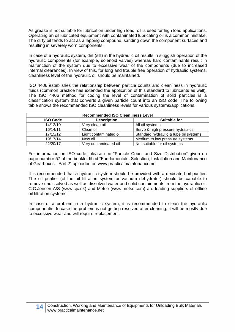
As grease is not suitable for lubrication under high load, oil is used for high load applications. Operating an oil lubricated equipment with contaminated lubricating oil is a common mistake. The dirty oil tends to act as a lapping compound, sanding down the component surfaces and resulting in severely worn components. In case of a hydraulic system, dirt (silt) in the hydraulic oil results in sluggish operation of the hydraulic components (for example, solenoid valves) whereas hard contaminants result in malfunction of the system due to excessive wear of the components (due to increased internal clearances). In view of this, for long and trouble free operation of hydraulic systems, cleanliness level of the hydraulic oil should be maintained. ISO 4406 establishes the relationship between particle counts and cleanliness in hydraulic fluids (common practice has extended the application of this standard to lubricants as well). The ISO 4406 method for coding the level of contamination of solid particles is a classification system that converts a given particle count into an ISO code. The following table shows the recommended ISO cleanliness levels for various systems/applications.
Recommended ISO Cleanliness Level
ISO Code Description Suitable for
14/12/10 Very clean oil All oil systems
16/14/11 Clean oil Servo & high pressure hydraulics
17/15/12 Light contaminated oil Standard hydraulic & lube oil systems
19/17/14 New oil Medium to low pressure systems
22/20/17 Very contaminated oil Not suitable for oil systems
For information on ISO code, please see “Particle Count and Size Distribution” given on page number 57 of the booklet titled “Fundamentals, Selection, Installation and Maintenance of Gearboxes - Part 2” uploaded on www.practicalmaintenance.net. It is recommended that a hydraulic system should be provided with a dedicated oil purifier. The oil purifier (offline oil filtration system or vacuum dehydrator) should be capable to remove undissolved as well as dissolved water and solid containments from the hydraulic oil. C.C.Jensen A/S (www.cjc.dk) and Metso (www.metso.com) are leading suppliers of offline oil filtration systems. In case of a problem in a hydraulic system, it is recommended to clean the hydraulic component/s. In case the problem is not getting resolved after cleaning, it will be mostly due to excessive wear and will require replacement.
15 Construction, Working and Maintenance of Equipments for Unloading Bulk Materials www.practicalmaintenance.net
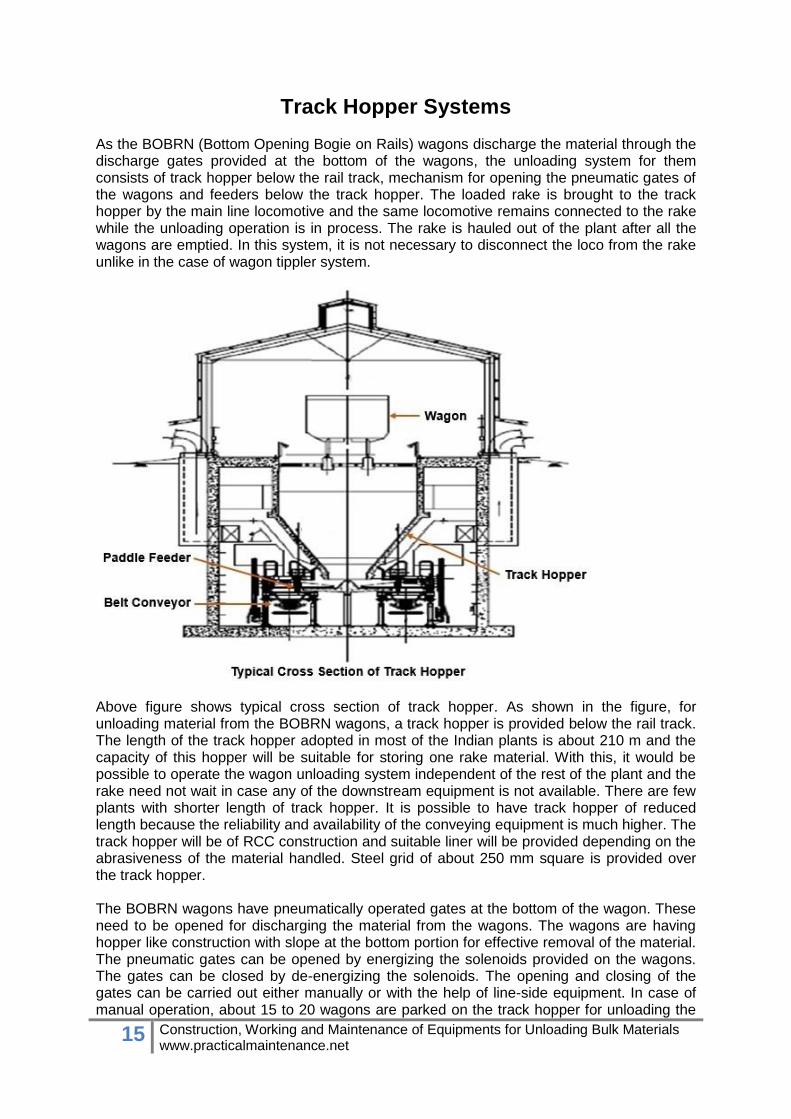
Track Hopper Systems As the BOBRN (Bottom Opening Bogie on Rails) wagons discharge the material through the discharge gates provided at the bottom of the wagons, the unloading system for them consists of track hopper below the rail track, mechanism for opening the pneumatic gates of the wagons and feeders below the track hopper. The loaded rake is brought to the track hopper by the main line locomotive and the same locomotive remains connected to the rake while the unloading operation is in process. The rake is hauled out of the plant after all the wagons are emptied. In this system, it is not necessary to disconnect the loco from the rake unlike in the case of wagon tippler system.
Above figure shows typical cross section of track hopper. As shown in the figure, for unloading material from the BOBRN wagons, a track hopper is provided below the rail track. The length of the track hopper adopted in most of the Indian plants is about 210 m and the capacity of this hopper will be suitable for storing one rake material. With this, it would be possible to operate the wagon unloading system independent of the rest of the plant and the rake need not wait in case any of the downstream equipment is not available. There are few plants with shorter length of track hopper. It is possible to have track hopper of reduced length because the reliability and availability of the conveying equipment is much higher. The track hopper will be of RCC construction and suitable liner will be provided depending on the abrasiveness of the material handled. Steel grid of about 250 mm square is provided over the track hopper. The BOBRN wagons have pneumatically operated gates at the bottom of the wagon. These need to be opened for discharging the material from the wagons. The wagons are having hopper like construction with slope at the bottom portion for effective removal of the material. The pneumatic gates can be opened by energizing the solenoids provided on the wagons. The gates can be closed by de-energizing the solenoids. The opening and closing of the gates can be carried out either manually or with the help of line-side equipment. In case of manual operation, about 15 to 20 wagons are parked on the track hopper for unloading the

16 Construction, Working and Maintenance of Equipments for Unloading Bulk Materials www.practicalmaintenance.net
material. Once this batch of wagons is unloaded, the next batch of wagons will be pushed forward and parked on the track hopper for unloading operation. This process is repeated till the completion of unloading operation. In case of line-side equipment, the unloading operation could be done while the rake is in motion. The compressors required for supplying the compressed air could be either mounted on the locomotive used for hauling the rake or could be in a separate room near the track hopper.
Above figure shows typical underground view of a track hopper. As shown in the figure, trolley mounted paddle/plow feeders (machines having curved blades mounted on a vertical shaft) are provided below the track hopper for evacuating the material from the hopper. They remove material from bottom of the track hopper and feed the belt conveyor below it.

17 Construction, Working and Maintenance of Equipments for Unloading Bulk Materials www.practicalmaintenance.net
Trolley of the paddle feeder is mounted on rails for moving the paddle feeder from one end to other end of the track hopper. Hence, a paddle feeder has two drives. One drive is for the paddle feeder and the other drive is for its trolley. As shown in above figure, the paddle feeder is generally driven by a hydraulic motor for smoother operation. As shown in the following figure, the trolley is driven by an electric motor.
Sometimes the trolley drive is not supported adequately leading to frequent failures. As shown in above figure, the problem can be resolved by providing additional supports. The layout of the rail tracks shall be such that the track will be straight and horizontal for one rake length on the inhaul side and also on the outhaul side. In case it is not possible to have straight length to accommodate one full rake on either side, at least about 250 m on either sides of the track shall be made straight and the balance could be on a smooth curve. It would be preferable to provide Merry Go Round (MGR) system of rail track so that the rake can enter the plant in one direction and go out of the plant without any need of disconnecting the loco from the rake.

18 Construction, Working and Maintenance of Equipments for Unloading Bulk Materials www.practicalmaintenance.net
As shown in above figure, in case BOBRN wagons are not available, wagons with gates on the sides (BOXNHL type wagons) are unloaded manually. At pit head power plants many times a merry-go-round system is used. In this system, a wagon is unloaded while it is moving with a slow speed on about 125 m long track hopper. In India, NTPC uses bottom discharge wagons in a merry-go-round system. In this system, the wagons are fitted with automatic gate opening system. The gate operation i.e. opening and closing is actuated by mechanism (rail) along the track. When a wagon of the rack enters on track hopper, it's gate gets opened automatically. Simultaneously, the rack is moving at slow speed. The speed is such that when the wagon travels from entry point to the exit point of track hopper, the contents of the wagon gets discharged automatically by gravity. Thus in this system, time taken by the rack to get unloaded is short, just the passage time of the entire rack over track hopper.
19 Construction, Working and Maintenance of Equipments for Unloading Bulk Materials www.practicalmaintenance.net
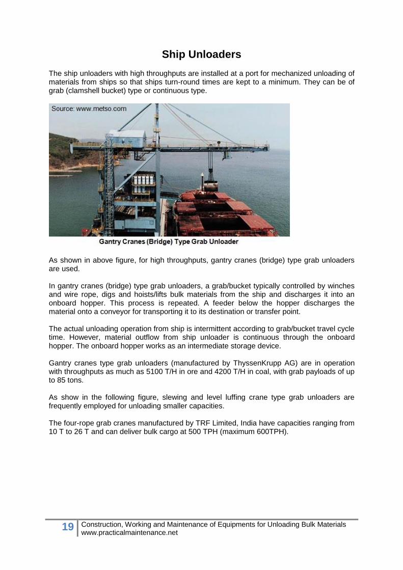
Ship Unloaders The ship unloaders with high throughputs are installed at a port for mechanized unloading of materials from ships so that ships turn-round times are kept to a minimum. They can be of grab (clamshell bucket) type or continuous type.
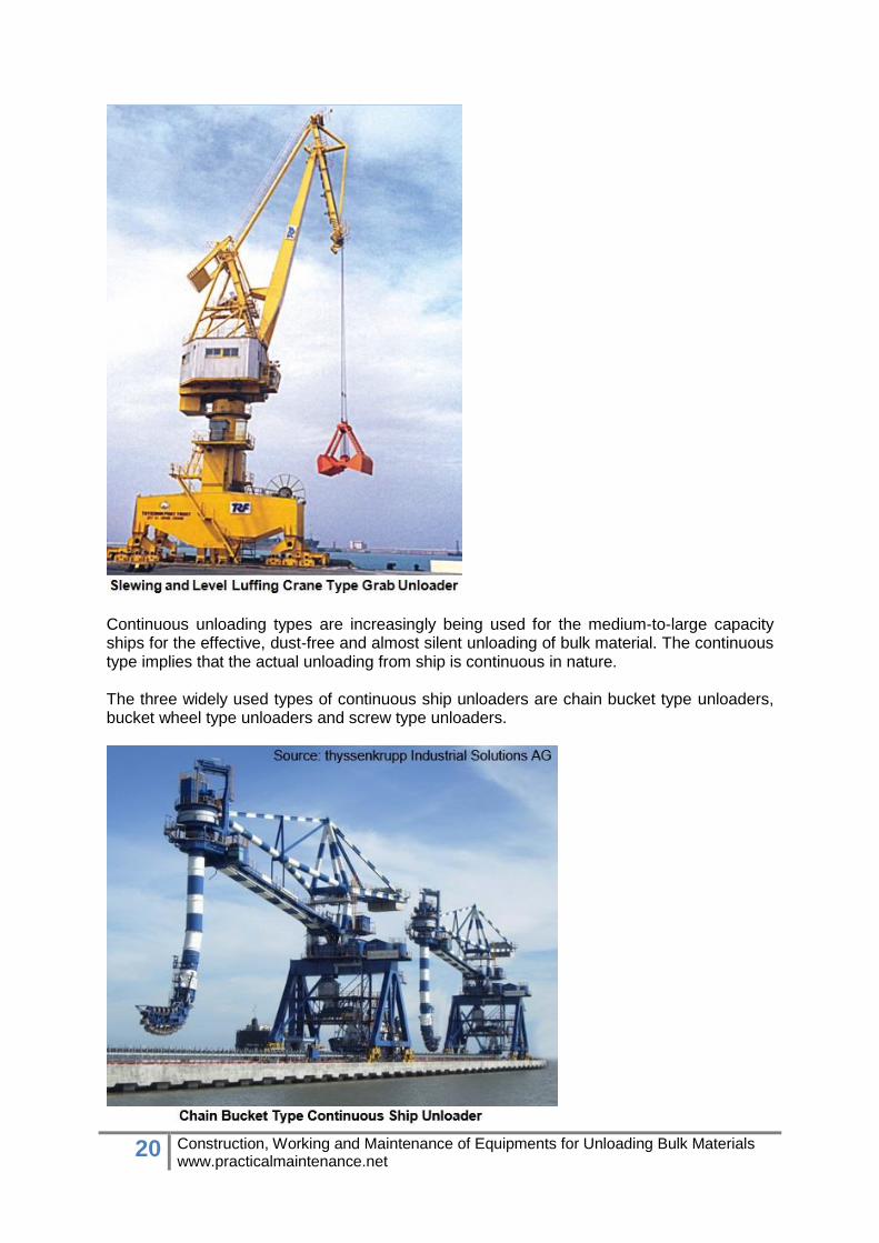
As shown in above figure, for high throughputs, gantry cranes (bridge) type grab unloaders are used. In gantry cranes (bridge) type grab unloaders, a grab/bucket typically controlled by winches and wire rope, digs and hoists/lifts bulk materials from the ship and discharges it into an onboard hopper. This process is repeated. A feeder below the hopper discharges the material onto a conveyor for transporting it to its destination or transfer point. The actual unloading operation from ship is intermittent according to grab/bucket travel cycle time. However, material outflow from ship unloader is continuous through the onboard hopper. The onboard hopper works as an intermediate storage device. Gantry cranes type grab unloaders (manufactured by ThyssenKrupp AG) are in operation with throughputs as much as 5100 T/H in ore and 4200 T/H in coal, with grab payloads of up to 85 tons. As show in the following figure, slewing and level luffing crane type grab unloaders are frequently employed for unloading smaller capacities. The four-rope grab cranes manufactured by TRF Limited, India have capacities ranging from 10 T to 26 T and can deliver bulk cargo at 500 TPH (maximum 600TPH).
20 Construction, Working and Maintenance of Equipments for Unloading Bulk Materials www.practicalmaintenance.net
Continuous unloading types are increasingly being used for the medium-to-large capacity ships for the effective, dust-free and almost silent unloading of bulk material. The continuous type implies that the actual unloading from ship is continuous in nature. The three widely used types of continuous ship unloaders are chain bucket type unloaders, bucket wheel type unloaders and screw type unloaders.

21 Construction, Working and Maintenance of Equipments for Unloading Bulk Materials www.practicalmaintenance.net
Above figure shows photograph of a chain bucket type continuous ship unloader.
Above figure shows photograph of a bucket wheel type continuous ship unloader. The bucket wheel type continuous ship unloader is lighter than the bucket chain type one because it has a compact digging element with high digging capacity and a rubber belt type elevating conveyor with high speed.
Above figure shows construction of a screw type continuous ship unloader. The screw type continuous ship unloader conveys the material from the holds of the ship/barge to an outlet chute on the gantry conveyor for further transport to a belt (dock/yard) conveyor installed
22 Construction, Working and Maintenance of Equipments for Unloading Bulk Materials www.practicalmaintenance.net
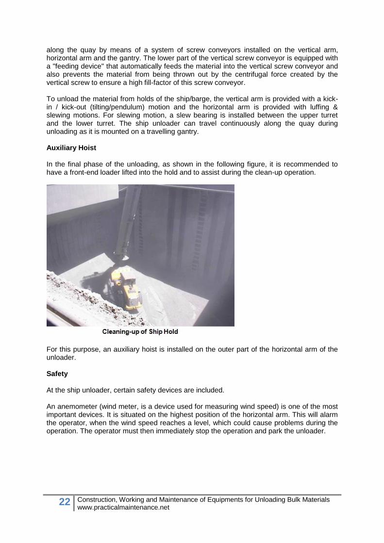
along the quay by means of a system of screw conveyors installed on the vertical arm, horizontal arm and the gantry. The lower part of the vertical screw conveyor is equipped with a "feeding device" that automatically feeds the material into the vertical screw conveyor and also prevents the material from being thrown out by the centrifugal force created by the vertical screw to ensure a high fill-factor of this screw conveyor. To unload the material from holds of the ship/barge, the vertical arm is provided with a kick-in / kick-out (tilting/pendulum) motion and the horizontal arm is provided with luffing & slewing motions. For slewing motion, a slew bearing is installed between the upper turret and the lower turret. The ship unloader can travel continuously along the quay during unloading as it is mounted on a travelling gantry. Auxiliary Hoist In the final phase of the unloading, as shown in the following figure, it is recommended to have a front-end loader lifted into the hold and to assist during the clean-up operation.
For this purpose, an auxiliary hoist is installed on the outer part of the horizontal arm of the unloader. Safety At the ship unloader, certain safety devices are included. An anemometer (wind meter, is a device used for measuring wind speed) is one of the most important devices. It is situated on the highest position of the horizontal arm. This will alarm the operator, when the wind speed reaches a level, which could cause problems during the operation. The operator must then immediately stop the operation and park the unloader.
23 Construction, Working and Maintenance of Equipments for Unloading Bulk Materials www.practicalmaintenance.net
Truck Unloaders Many times material is received in trucks. In case of tipper truck (dumper), the material can be unloaded by the truck tippling arrangement installed on the tipper truck. However, in case the material is received by normal trucks (without tippling arrangement), hydraulic truck unloader/tippler can be used for mechanized unloading.
Tipper Trucks
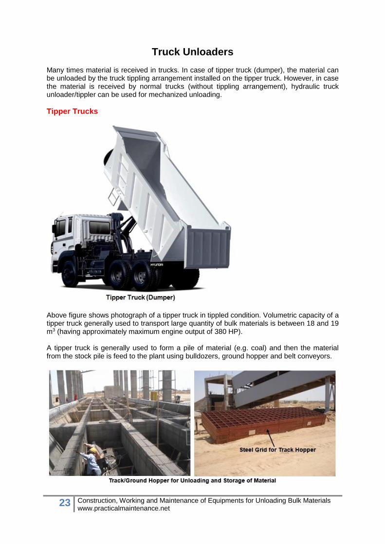
Above figure shows photograph of a tipper truck in tippled condition. Volumetric capacity of a tipper truck generally used to transport large quantity of bulk materials is between 18 and 19 m3 (having approximately maximum engine output of 380 HP). A tipper truck is generally used to form a pile of material (e.g. coal) and then the material from the stock pile is feed to the plant using bulldozers, ground hopper and belt conveyors.

24 Construction, Working and Maintenance of Equipments for Unloading Bulk Materials www.practicalmaintenance.net
As shown in above figure, sometimes a track/ground hopper for unloading and storage of material is used for the material unloaded from a tipper truck. The track hopper is of RCC construction and suitable liner is provided depending on the abrasiveness of the material handled. A steel grid of about 250 mm square is provided over the track hopper. Trolley mounted paddle feeders are provided below the track hopper for evacuating the material from the hopper. They remove material from bottom of the track hopper and feed the belt conveyor below it.
As shown in above figure, since the capacity of these paddle feeders is small (compared to track hoppers for unloading wagons), they are usually driven by electric motors.
Hydraulic Truck Unloader (Tippler) A hydraulic truck unloader is used to unload the material if it is received by normal trucks. The hydraulic truck unloader essentially consists of an anti-skid platform of suitable width along with guide rails for positioning of the truck and a pair of heavy duty lift cylinder to tilt the platform. All the operations (like tilting of the top platform and harnessing the truck on the platform) are actuated from a hydraulic power pack placed near the truck unloader along with a control panel with push buttons. After the material is unloaded in the hopper located behind the unloader, it is feed to the plant through a belt conveyor. Generally, a vibrating feeder is used to feed material to the belt conveyor. The two types of hydraulic truck unloader are available in the market.

25 Construction, Working and Maintenance of Equipments for Unloading Bulk Materials www.practicalmaintenance.net
As shown in above figure, in the conventional type, the truck to be unloaded is driven backwards through a ramp onto the unloader platform till the rear wheels of the truck get support from the resting pads of the back stoppers. After this, the front anchoring chains are harnessed to the front axle and the platform is tilted. Material usually starts falling in the hopper at the rear end from a tilting angle of 30°.
As shown in above figure, in the advanced type, the ramp is not required to place the truck on the platform because the platform level of the hydraulic truck unloader matches with the ground level.
26 Construction, Working and Maintenance of Equipments for Unloading Bulk Materials www.practicalmaintenance.net
References Rail car unloaders by thyssenkrupp Industrial Solutions AG (www.thyssenkrupp-industrial-solutions.com). Wagon Tippler with Side Arm Charger by TRF Limited (www.trf.co.in). Wagon Tipplers by Elecon EPC Projects Ltd. (www.eleconepc.com). G-33 (Rev. 1), Technical Pamphlet for Requirements of Tippler Installation for Approval by RDSO Issued by Research Designs and Standards Organisation, Ministry of Railways, Lucknow - 226 011, India. Wagon Loading and Unloading System by H Ramakrishna, Tata Consulting Engineers Limited, Bangalore, India (www.tce.co.in). Grab bucket unloaders by Mesto (www.metso.com). Level Luffing Cranes by TRF Limited. Continuous ship unloaders by ThyssenKrupp Industrial Solutions AG Bucket Wheel type Continuous Ship Unloader by Kawasaki Heavy Industries, Ltd. (https://global.kawasaki.com). Ship Unloader by FLSmidth (www.flsmidth.com). Hydraulic Truck Unloader by Jaypee Engg. & Hydraulic Equipment Company Limited (www.jehel.com).