Embed Size (px)
Citation preview
Construction of New Buildings for IIT Madras Research Park – Phase – II, SH: -
Electrical works – Package-1– Substation works
Scope of work Page 1 of 182 Section 3
1. SCOPE OF WORK
The general character and the scope of work to be carried out under this contract are
illustrated in Drawings, Specifications and Schedule of Quantities. The Contractor shall carry out and complete the said work under this contract in every respect in conformity with the contract documents and with the direction of and to the satisfaction of the Owner’s site representative. The contractor shall furnish all labour, materials and equipment (except those to be supplied by the owner) as listed under Schedule of Quantities and specified otherwise, transportation and incidental necessary for supply, installation, testing and commissioning of the complete electrical system as described in the Specifications and as shown on the drawings. This also includes any material, equipment, appliances and incidental work not specifically mentioned herein or noted on the Drawings/Documents as being furnished or installed, but which are necessary and customary to be performed under this contract. The electrical system shall comprise of (but not limited to) the following:
1.1 33KV/11KV HT VCB Panel Supply & Installation.
1.2 DG synchronizing panels.
1.3 HT/LT Cables.
1.4 Power & Distribution Transformer Installation.
1.5 LT Panels.
1.6 Utility Panels..
1.7 Safety Equipments
1.8 Earthing.
1.9 Cable trays
1.10 Rising Main Installation.
1.11 Cabling system.
Construction of New Buildings for IIT Madras Research Park – Phase – II, SH: -
Electrical works – Package-1– Substation works
Scope of work Page 2 of 182 Section 3
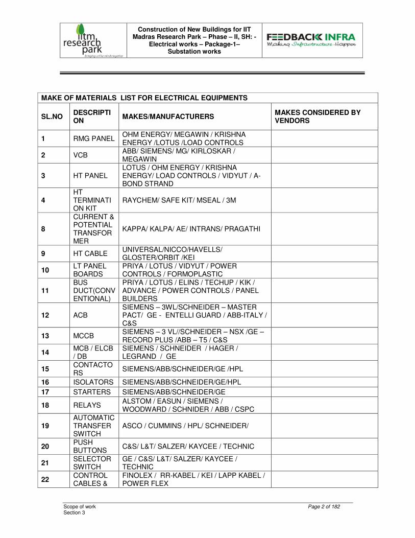
MAKE OF MATERIALS LIST FOR ELECTRICAL EQUIPMENTS
SL.NO DESCRIPTION
MAKES/MANUFACTURERS MAKES CONSIDERED BY VENDORS
1 RMG PANEL OHM ENERGY/ MEGAWIN / KRISHNA ENERGY /LOTUS /LOAD CONTROLS
2 VCB ABB/ SIEMENS/ MG/ KIRLOSKAR / MEGAWIN
3 HT PANEL LOTUS / OHM ENERGY / KRISHNA ENERGY/ LOAD CONTROLS / VIDYUT / A-BOND STRAND
4 HT TERMINATION KIT
RAYCHEM/ SAFE KIT/ MSEAL / 3M
8
CURRENT & POTENTIAL TRANSFORMER
KAPPA/ KALPA/ AE/ INTRANS/ PRAGATHI
9 HT CABLE UNIVERSAL/NICCO/HAVELLS/ GLOSTER/ORBIT /KEI
10 LT PANEL BOARDS
PRIYA / LOTUS / VIDYUT / POWER CONTROLS / FORMOPLASTIC
11 BUS DUCT(CONVENTIONAL)
PRIYA / LOTUS / ELINS / TECHUP / KIK / ADVANCE / POWER CONTROLS / PANEL BUILDERS
12 ACB SIEMENS – 3WL/SCHNEIDER – MASTER PACT/ GE - ENTELLI GUARD / ABB-ITALY / C&S
13 MCCB SIEMENS – 3 VL//SCHNEIDER – NSX /GE – RECORD PLUS /ABB – T5 / C&S
14 MCB / ELCB / DB
SIEMENS / SCHNEIDER / HAGER / LEGRAND / GE
15 CONTACTORS
SIEMENS/ABB/SCHNEIDER/GE /HPL
16 ISOLATORS SIEMENS/ABB/SCHNEIDER/GE/HPL
17 STARTERS SIEMENS/ABB/SCHNEIDER/GE
18 RELAYS ALSTOM / EASUN / SIEMENS / WOODWARD / SCHNIDER / ABB / CSPC
19 AUTOMATIC TRANSFER SWITCH
ASCO / CUMMINS / HPL/ SCHNEIDER/
20 PUSH BUTTONS
C&S/ L&T/ SALZER/ KAYCEE / TECHNIC
21 SELECTOR SWITCH
GE / C&S/ L&T/ SALZER/ KAYCEE / TECHNIC
22 CONTROL CABLES &
FINOLEX / RR-KABEL / KEI / LAPP KABEL / POWER FLEX
Construction of New Buildings for IIT Madras Research Park – Phase – II, SH: -
Electrical works – Package-1– Substation works
Scope of work Page 3 of 182 Section 3
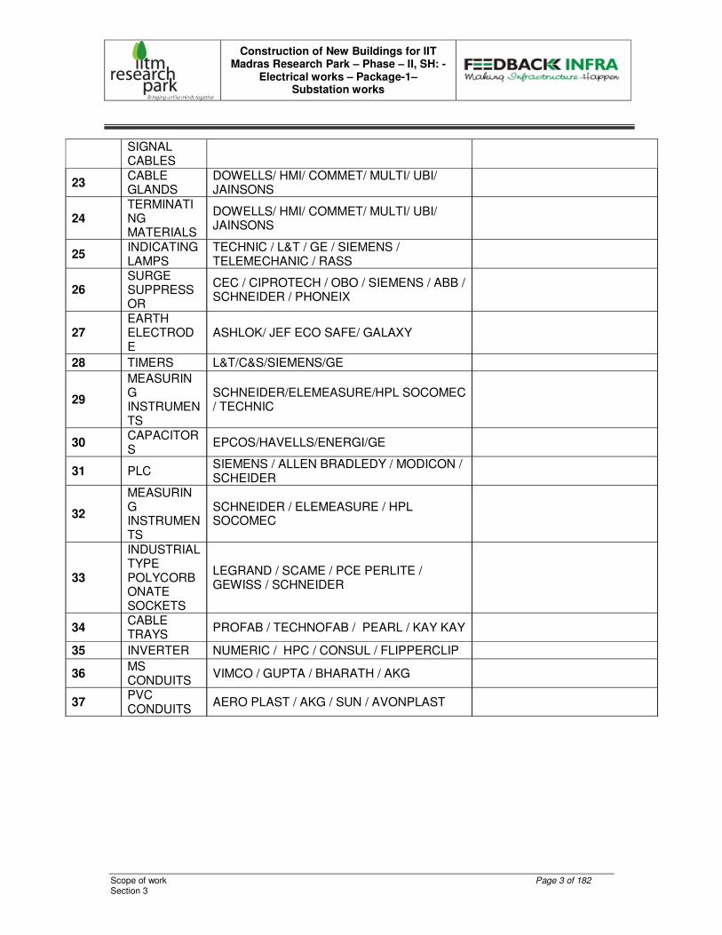
SIGNAL CABLES
23 CABLE GLANDS
DOWELLS/ HMI/ COMMET/ MULTI/ UBI/ JAINSONS
24 TERMINATING MATERIALS
DOWELLS/ HMI/ COMMET/ MULTI/ UBI/ JAINSONS
25 INDICATING LAMPS
TECHNIC / L&T / GE / SIEMENS / TELEMECHANIC / RASS
26 SURGE SUPPRESSOR
CEC / CIPROTECH / OBO / SIEMENS / ABB / SCHNEIDER / PHONEIX
27 EARTH ELECTRODE
ASHLOK/ JEF ECO SAFE/ GALAXY
28 TIMERS L&T/C&S/SIEMENS/GE
29
MEASURING INSTRUMENTS
SCHNEIDER/ELEMEASURE/HPL SOCOMEC / TECHNIC
30 CAPACITORS
EPCOS/HAVELLS/ENERGI/GE
31 PLC SIEMENS / ALLEN BRADLEDY / MODICON / SCHEIDER
32
MEASURING INSTRUMENTS
SCHNEIDER / ELEMEASURE / HPL SOCOMEC
33
INDUSTRIAL TYPE POLYCORBONATE SOCKETS
LEGRAND / SCAME / PCE PERLITE / GEWISS / SCHNEIDER
34 CABLE TRAYS
PROFAB / TECHNOFAB / PEARL / KAY KAY
35 INVERTER NUMERIC / HPC / CONSUL / FLIPPERCLIP
36 MS CONDUITS
VIMCO / GUPTA / BHARATH / AKG
37 PVC CONDUITS
AERO PLAST / AKG / SUN / AVONPLAST

Construction of New Buildings for IIT Madras Research Park – Phase – II, SH: -
Electrical works – Package-1– Substation works
Scope of work Page 4 of 182 Section 3
TECHNICAL SPECIFICATION
TECHNICAL SPECIFICATION FOR 33 KV HT INDOOR RMG PANEL
INTRODUCTION
This specification covers the design, manufacture and supply of 33 KV RMG incorporating 33 KV draw-out vacuum circuit breaker and Load break Switches. The Ring Main Gear shall be of INDOOR type and rated for a fault level of 1500MVA, 26.2 KA, continuous current and shall be suitable for operation on 3 phase 3 wire 33 KV earthed System. The subject RMG is to be supplied in accordance with IS regulations and should satisfy the TNEB requirements. The Load Break Switch, Vacuum Circuit Breaker and all accessories in the RMG shall be as per the detailed specification for each of them and suitable for operation for the system voltage indicated. It shall be capable of continuous and reliable operation at the full load rating specified where continuity of operation is of prime importance. Workmanship shall be of the highest grade and the entire construction in accordance with the best modern practice. The RMG shall be capable of withstanding the severest stresses likely to occur in actual service and of resisting rough handling during transport. Circuit breaker shall be suitable to withstand in-rush Magnetizing currents of HT Panels. The INDOOR RMG as per the equipment description shall be completely factory assembled and ready for installation at site. The INDOOR RMG shall be of dust and vermin proof of MS sheet metal enclosure and this enclosure shall be tested with degree of protection IP 55 as per IS 3427. EQUIPMENT DESCRIPTION The Ring Main Gear shall be of INDOOR type and shall consists of 2Nos. 33 KV, short time rated (AS PER BOQ), Air Break / Load Break Switch with suitably interlocked earth switch, front operated, spring assisted, manual closing mechanism for controlling the incoming supply and 1 no 33 KV, horizontal draw out horizontal isolation Vacuum Circuit Breaker fitted with motor operated spring charging mechanism, for controlling the outgoing supply.
Construction of New Buildings for IIT Madras Research Park – Phase – II, SH: -
Electrical works – Package-1– Substation works
Scope of work Page 5 of 182 Section 3
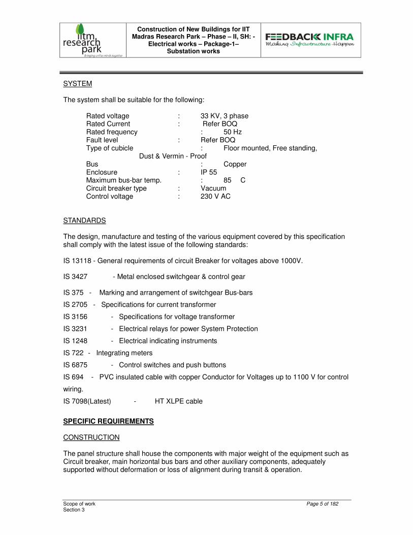
SYSTEM The system shall be suitable for the following:
Rated voltage : 33 KV, 3 phase Rated Current : Refer BOQ Rated frequency : 50 Hz Fault level : Refer BOQ Type of cubicle : Floor mounted, Free standing,
Dust & Vermin - Proof Bus : Copper Enclosure : IP 55 Maximum bus-bar temp. : 85 � C Circuit breaker type : Vacuum Control voltage : 230 V AC
STANDARDS The design, manufacture and testing of the various equipment covered by this specification shall comply with the latest issue of the following standards:
IS 13118 - General requirements of circuit Breaker for voltages above 1000V.
IS 3427 - Metal enclosed switchgear & control gear
IS 375 - Marking and arrangement of switchgear Bus-bars
IS 2705 - Specifications for current transformer
IS 3156 - Specifications for voltage transformer
IS 3231 - Electrical relays for power System Protection
IS 1248 - Electrical indicating instruments
IS 722 - Integrating meters
IS 6875 - Control switches and push buttons
IS 694 - PVC insulated cable with copper Conductor for Voltages up to 1100 V for control
wiring.
IS 7098(Latest) - HT XLPE cable
SPECIFIC REQUIREMENTS CONSTRUCTION The panel structure shall house the components with major weight of the equipment such as Circuit breaker, main horizontal bus bars and other auxiliary components, adequately supported without deformation or loss of alignment during transit & operation.
Construction of New Buildings for IIT Madras Research Park – Phase – II, SH: -
Electrical works – Package-1– Substation works
Scope of work Page 6 of 182 Section 3
The Switch gears shall have necessary internal sheet metal barrier to form separate compartments for buses, instruments, relays, cable connections etc. Adequate barriers shall permit the personnel to work safely within an empty compartment with the bus bars energized. Checking and removal of components shall be possible without disturbing the feeder. All auxiliary equipment shall be easily accessible to facilitate their operation and maintenance. It shall be possible to set all relays and measuring instruments without de energizing the Switchgear.
All doors and openings shall be fitted with neoprene gaskets with fasteners designed to ensure proper compression of the gaskets. When covers are provided in place of doors, generous overlap shall be assured between sheet steel surfaces with closely spaced fasteners to prevent the entry of dust.
The panel shall have a rear cable chamber housing the cable and connections. The design shall ensure generous availability of space for easy installation and maintenance. Cabling and adequate safety for working in one section without coming into accidental contact with live part in an adjacent section.
The HT switchboard shall be constructed only with materials capable of withstanding the mechanical, electrical and thermal stresses, as well as the effects of humidity, which are likely to be encountered in normal service. All insulating materials used in construction of the equipment shall be non-hygroscopic materials, duly treated to withstand the effects of high humidity, high temperature and tropical ambient service conditions. Creepage distances shall comply with those specified in relevant standards.
The panel shall be provided with space heater to prevent condensation and the same shall be equipped with differential thermostat to automatically cut in and cut out the heater so as to maintain interior temperature, 5�C above the ambient and should have manual disconnect switch.
The total depth of the panel shall be adequate to cater for proper cabling space.
Provision shall be made for permanently earthing the frames and other metal parts of the switchboard through a copper earth bus bar running throughout the full length of the switchboard at the bottom. Draw-out type switching units shall have sliding ground contact. It shall be possible to earth the switchboard at two independent points on either end, for connections to the external earthing network of the plant.
It shall be possible to extend the switchgear in either direction, whenever required. Ends of bus-bars shall be suitably drilled for this purpose.
Suitable eye bolt for lifting of panel shall be provided. On removing the eye bolts, the recess should be suitably covered, avoiding access into the panel.
BUSBARS
The bus-bars shall be epoxy moulded or PVC sleeved and made of high conductivity electrolytic grade Copper. The current in all current carrying paths should not exceed 1.2 A / sq mm.
Construction of New Buildings for IIT Madras Research Park – Phase – II, SH: -
Electrical works – Package-1– Substation works
Scope of work Page 7 of 182 Section 3
The bus bar chamber shall be totally maintenance free.
The switchboard shall comprise of 3 phase main bus-bars. The bus bar shall be of uniform cross-section throughout and shall be sized to continuously carry the rated current without exceeding the temperature rise of 40ºC over the maximum ambient temperature of 45ºC. Bus-bars shall be colour coded for easy identification of individual phases.
Bus bars shall be supported at regular intervals and both bus-bars and supports shall be adequately sized and braced to withstand short circuit level, without deformation. All bus supports shall be non-carbonizing material, resistant to acid alkalies and shall have non-hygroscopic characteristics.
For lengthy bus-bars suitable expansion joints shall be provided. Thermal design of the bus-bars shall be based on the installation of the switchgear in poorly ventilated condition.
Bus-bars shall be housed in a separate chamber, which shall be accessible for inspection only with special tools.
The rating of bus-bars shall be same as that of incomer breaker rating.
INSULATION LEVELS
The insulation level corresponding to the rated voltage are:
(α) Normal Voltage : 33 kV
1. Highest system voltage : 36kV
2. One minute Power Frequency : 70 kV RMS
3. Withstand voltage
4.4.4.4. 1.2/50 micro second impulse : 170 kV Peak
Busbar Minimum Clearance
5.5.5.5. Phase to phase : 350 mm
6.6.6.6. Phase to earth : 270 mm
AIRBREAK / LOAD BREAK SWITCH PANEL (2Nos.) The Air break / Load Break switch panel shall consist of the following:
One number 33KV, 630 Amps, 26.2 KA rated, HT Air Break / Load break switch suitably interlocked with earth switch. It shall be with front operated spring assisted manual mechanism & with 2No + 2Nc Auxiliary contacts & operating handle. ON /OFF indication Lamps : 2Nos. 630 A Copper bus-bars : 1Set Space Heater with thermostat & switch control : 1Set
Construction of New Buildings for IIT Madras Research Park – Phase – II, SH: -
Electrical works – Package-1– Substation works
Scope of work Page 8 of 182 Section 3
Lamp Holder with Door Switch & lamp : 1Set Provision to receive the incoming 33 KV, XLPE cable at Bottom. The above Load Break switch panel shall be trunked, one on either side of the VCB panel. The Load Break Switch shall be suitable for panel mounting type. It shall be of simple and compact construction with suitable graded MOULDED EPOXY support, double switch-blades and forged contacts with arc quenching chamber, locking pin and loop less current path. The main frame shall be of welded steel and contacts shall be mounted in Epoxy insulators. The upper fixed contact shall house the arc quenching chamber and connecting terminal. It shall be equipped with spring assisted mechanism due to which constant speed can be achieved during opening & closing and shall be provided with stored energy tripping device. They shall be built as per IS 9920 / IEC 265. They shall be capable of make and break at the normal rated current and shall also make the short circuit current earthed, without endangering the operator Fully rated Earth switch interlocked with Load Break Switch shall be provided as per the requirement of TNEB as a Factory Fitted Accessory.
THE VCB BREAKER PANEL
33KV, 1500 MVA, VACUUM CIRCUIT BREAKER – INCOMING & OUTGOING FEEDER
Circuit Breakers shall be triple pole, vacuum circuit breaker, and draw-out type. The normal current rating of breakers should be at least 1.6 times the maximum loading of circuit it controls. The rupturing capacity of breaker should be at least 1.25 times the calculated fault level of bus-bars. The breakers shall have motor operated spring charged mechanism with anti-pumping contactor. The control circuit shall be suitable for local as well as remote control. The breaker sockets and plugs should be heavily silver-plated. It should have adequate auxiliary contacts required by plant control schematics plus 20% spare contacts for future use. Auxiliary contactors or relays should be used to multiply the contacts. The operating mechanism shall be robust design with a minimum number of linkages to ensure maximum reliability. The operating mechanism shall be such that the breaker is at all times free to open immediately, when the trip coil is energized. It is to be ensured that all the three poles open/close in unison to avoid any eventuality of single-phasing operation. The breaker shall have the distinct positions indicating:
1. ‘Service’ Position : With main auxiliary contacts Connected.
Construction of New Buildings for IIT Madras Research Park – Phase – II, SH: -
Electrical works – Package-1– Substation works
Scope of work Page 9 of 182 Section 3
2. ‘Test’ Position : With power contacts fully disconnected and control circuit contacts connected.
3. ‘Isolated’ Position : With both power and control circuit contacts fully disconnected.
4. Earthing : While drawing-in the Breaker, earth shall Come into contact before the test Position. While drawing-out the Breaker, earth shall disconnect after the test position
The circuit breaker can be closed only when it is in one of the three positions or when it is fully out of the panel. The breaker trolley shall remain inside the cubicle even in the draw-out position. The trolley of the circuit breaker shall be so inter-locked that, it shall not be possible to isolate it from the connected position, or to plug it in from the isolated position with the breaker closed. It shall not be possible to open the breaker compartment door unless the breakers drawn to the isolated position or test position. Inadvertent ‘pushing in’ of the draw-out circuit breaker in service position, with auxiliary circuit plug not in the position shall be prevented. Automatic safety shutters shall be provided to ensure the inaccessibility of live parts after the breaker is drawn-out. The circuit breaker trolley shall be provided with a heavy-duty self-aligning earth contact, which shall make before and break after the main isolating contacts during insertion into and withdrawal from the service position of the breaker. Even in the isolated position, positive earthing contact should exist.
Circuit breakers of identical rating shall be interchangeable. EARTH SWITCHES Each breaker shall be provided with independent earth switch (make proof) to earth the cable side terminals. Optionally an earth trolley shall be provided for the breaker.
CURRENT TRANSFORMERS The current transformer shall be of cast resin insulated type of adequate capacity and proper characteristics on secondary, as specified. The current density should not be more than 1 amp/ sq mm. C.Ts shall be wired with 4.0 Sq mm. PVC insulated, stranded, Copper conductor wires only. (AS PER TNEB – MRT NORMS.)
Construction of New Buildings for IIT Madras Research Park – Phase – II, SH: -
Electrical works – Package-1– Substation works
Scope of work Page 10 of 182 Section 3
CTs shall withstand stresses originated from short circuit. They shall have ratios, output and accuracy as specified. They shall be mounted on the switchboard stationary part. The secondary leads of the CTs from all panels should be terminated on the front of the board on easily accessible shorting type terminal connectors so that operation and maintenance can be carried out when the panels are in service. CTs shall be given the heat - run CT Shall be of Dual core (Core1-5VA, CL : 0.2 accuracy for metering & Core –2 15VA, CL : 5P 20 for protection ) POTENTIAL TRANSFORMER
The Potential Transformer shall be 50VA, 3Ph, Class 0.2 accuracy, 33KV/root 3 / 110V/root3 cast resin insulated DRAW OUT type. It shall be provided with MV / LT HRC fuses with sealing arrangement. THE ABOVE CURRENT & POTENTIAL TRANSFORMER SHALL BE GOT TESTED BY TNEB. THE VA RATING AND ACCURACY CLASS OF THE PT AND CT SHALL BE APPROVED BY THE LOCAL EB AUTHORITIES MEASURING INSTRUMENTS All measuring instruments shall be of flush mounting, Digital type and the size of the indicating instruments shall be of 96 x 96 Sq. mm. Cut out provision shall be made available to provide Tri vector meter by TNEB in the OUT GOING feeder of the RMG. Control and selector switches shall be of CAM operated rotary switches The voltmeter selector switches shall be of 10A rating to measure the voltage between phases with “OFF” . The ammeter selector switches shall be of 10A rating to measure the phase current through CTs. It shall be 0.2 class accuracy. All auxiliary equipment such as shunts, transducers, that are required shall be included. INDICATING LAMPS
Indicating lamps shall be of LED type & AC supply , low watt consumption, provided with series resistor where necessary and with translucent lamp covers. Bulbs and lenses shall be easily replaceable from the front.

Construction of New Buildings for IIT Madras Research Park – Phase – II, SH: -
Electrical works – Package-1– Substation works
Scope of work Page 11 of 182 Section 3
Following Indicating Lamps are required on the panel having lens colours as detailed below :
1. RYB Indication Lamps : RED, YELLOW, BLUE
2. Breaker ON : RED
3. Breaker OFF : GREEN
4. Breaker racked IN : RED
5. Breaker racked OUT : GREEN
6. Auto Trip : AMBER
7. Trip circuit healthy : WHITE
8. Spring charged : BLUE
9. Test position : YELLOW
RELAYS All protective relays shall be of electromechanical type, suitable for flush mounting and fitted with dust tight covers. All relays shall be mounted on the front of the panel and shall be specified as per requirement. The current and the voltage coils shall be provided as specified.
All relays shall have built-in flag to indicate operation. It shall be possible to reset the flag without opening the relay case. All tripping relays shall be suitable to operate on the specified voltage.
Three Over current & one Earth fault relay with instantaneous trip shall be provided
with following settings O/L 50-200% and E/F 20-80% relay. The IDMTL relay setting range should be Phase fault: 10-200% for IDMT in steps of 5% 250-2000% for H/S in steps of 10% Earth fault: 10-100% for IDMT in steps of 5% 100-800% for H/S in steps of 10% Characteristics type: Normal Inverse.
Note:- Trip delay time shall be 1.3 secs. AS PER TNEB – MRT NORMS.
CONTROL SWITCHES AND PUSH BUTTONS Control switches shall be of the heavy-duty rotary type with nameplates duly marked to show the operation. They shall be semi-flush mounting with only the front plate and operating handle projecting. Control switch shall be provided for Trip & Close the VCB with Neutral position. A Push button shall be available to check the healthiness of trip circuit. SURGE ARRESTOR
The Incoming 33 KV LBS Feeders of the RMG Panel Board shall be provided with Transient Voltage Surge Arrestors to protect the equipments from Surges, which are created due to lightning or switching action.
Construction of New Buildings for IIT Madras Research Park – Phase – II, SH: -
Electrical works – Package-1– Substation works
Scope of work Page 12 of 182 Section 3
AUXILIARY SWITCHES
Each circuit breaker shall be provided with auxiliary switches to interrupt the supply to the Closing mechanism and complete the trip circuit, when the circuit breaker is in the ‘Closed’ position and to cover all the necessary indication, interlocking and control facilities. All secondary connection between the fixed and moving portions of circuit breaker equipment shall be by means of plug and socket connections, arranged so as to eliminate positively any false indication when the moving portion is racked in to the service location. Each circuit breaker shall be provided with 4 NO + 4 NC auxiliary contacts as spare in addition to the other functional requirements.
INTERNAL WIRING Internal wiring and inter-panel wiring for all circuit shall be carried out with 1100/650V grade, single core, multi stranded, PVC insulated copper wire of minimum 2.5 sq. mm for CT and other control circuit. 4.0 sq.mm copper cable should be used for CT secondary wiring and 2.5sq.mm for PT secondary wiring with R,Y,B,N black coloured cable instead of colour sleeves. 2.5sq.mm Grey color and black color should be used for Dc control circuits and AC control circuits respectively. The wiring shall be neatly bunched, adequately supported and properly routed and terminated in the respective terminals with suitable lugs. There shall not be more than two wires connected at a terminal. Wires shall be identified by numbered ferrules at each end. The ferrules shall be of ring type and non-deteriorating material. All control circuits shall have HRC fuses mounted in front of the panel and shall be easily accessible. Internal wiring shall be done as per TNEB requirements.
TERMINAL BLOCKS AND TEST BLOCKS
Terminal blocks & Test blocks for the LT connections shall be of 650 V grade, stud type and of adequate current rating. The insulating barriers shall be provided between adjacent terminals. Provision shall be made for label inscription on terminal block. Cables should never be terminated directly on components. Provision shall be made for CT terminals shorting links, remote ON/OFF push button, remote ON/OFF indication and remote Ammeter. 20% spare terminals shall be provided on each terminal block. The link type test terminal block should be provided in CT circuit and the same should be provided in the metering core of CT secondary circuit of outgoing RMG panel with top and bottom connections
Construction of New Buildings for IIT Madras Research Park – Phase – II, SH: -
Electrical works – Package-1– Substation works
Scope of work Page 13 of 182 Section 3
CABLE TERMINATION The RMG panel shall be designed to facilitate 2 NOS 1R x 3C x 300 Sq mm for incoming and 1R x 3C x 300 Sq mm. 33 KV, XLPE insulated armoured aluminium cables for outgoing power connection. Ample space for connection of these cables shall be provided at the rear of the Switchboard. The cable termination arrangement shall be of adequate size and design to receive the required number of cables as specified. Proper cable clamping arrangements shall be provided. Detachable gland plate of 5mm thickness shall be provided for the cable entry into the panel. Sufficient space shall be provided to avoid sharp bending and facilitate easy connection. Suitable shrouds shall be provided to prevent accidental contact with live outgoing terminations of other feeders while carrying out maintenance on one feeder.
LABLES Nameplates of approved design shall be provided to represent circuit designation for each feeder. Material for nameplates shall be engraved Aluminium Sheet with white background with black letters and firmly secured with fasteners. PAINTING All metal surfaces shall be chemically cleaned, de-greased and pickled in acid to produce a smooth clean surface, free of scale, grease and rust. After cleaning, phosphating and passivation treatment, the surface shall be given two coats of zinc rich epoxy primer and baked in the oven. After primer, it shall be given two coat of stoving type Epoxy paint in light gray as per IS- Shade. Sufficient quantity of touch up paint shall be furnished for application at site. In addition one coat of fiber glass coating shall be given as protection.
LOUVERS
Louvers shall be provided with suitable mesh to facilitate the exit of the moisture trapped inside the RMG
TESTS
Pre-commissioning Checks and Tests shall be conducted at site by you at free of cost and certificate shall be furnished.
VISUAL TESTS Corrosion test
Construction of New Buildings for IIT Madras Research Park – Phase – II, SH: -
Electrical works – Package-1– Substation works
Scope of work Page 14 of 182 Section 3
Paint inspection Physical verification check Rubber gasket test. The following routines tests shall be conducted on the 33 KV switch board as per the relevant Indian Standards at the time of inspection. ROUTINE TESTS
The RMG Panel Board shall be tested for routine tests as per the relevant Indian Standards.
Milli volt drop test DC resistance test Contact resistance test HV test for 70 KV for 1 minute Endurance test (20 opening & closing operations) Control wiring tested with 2.8 KV applied Insulation Resistance test value before and after tests (500V Megger for control wiring & 5KV Megger for HV) Milli volt drop test on Rigid and expansion joints. Temperature Rise Test.
INSPECTION
Stage 1 Inspection : During Assembly of Panel Stage 2 Inspection : Before Dispatch The readiness should be informed at least fifteen days before the proposed date of Inspection.
COMMISSIONING The supplier shall render the service of his supervisor during the Installation and commissioning of the panels by other agency at free of cost.
The quoted price shall be inclusive of all necessary commissioning spares
DRAWINGS AND MANUALS The following drawings and manuals shall be submitted in six sets, for approval: General arrangement of circuit breaker showing Overall dimensions Terminal locations Total weight
Construction of New Buildings for IIT Madras Research Park – Phase – II, SH: -
Electrical works – Package-1– Substation works
Scope of work Page 15 of 182 Section 3
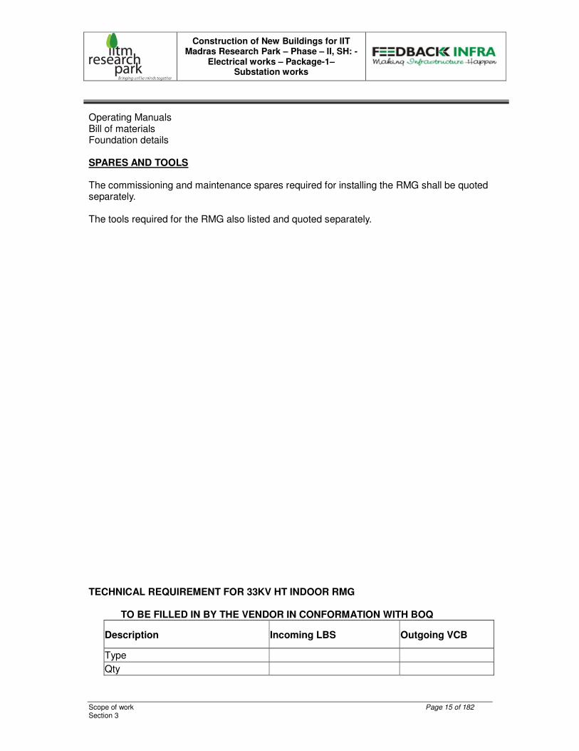
Operating Manuals Bill of materials Foundation details SPARES AND TOOLS The commissioning and maintenance spares required for installing the RMG shall be quoted separately. The tools required for the RMG also listed and quoted separately. TECHNICAL REQUIREMENT FOR 33KV HT INDOOR RMG
TO BE FILLED IN BY THE VENDOR IN CONFORMATION WITH BOQ
Description Incoming LBS Outgoing VCB
Type
Qty
Construction of New Buildings for IIT Madras Research Park – Phase – II, SH: -
Electrical works – Package-1– Substation works
Scope of work Page 16 of 182 Section 3
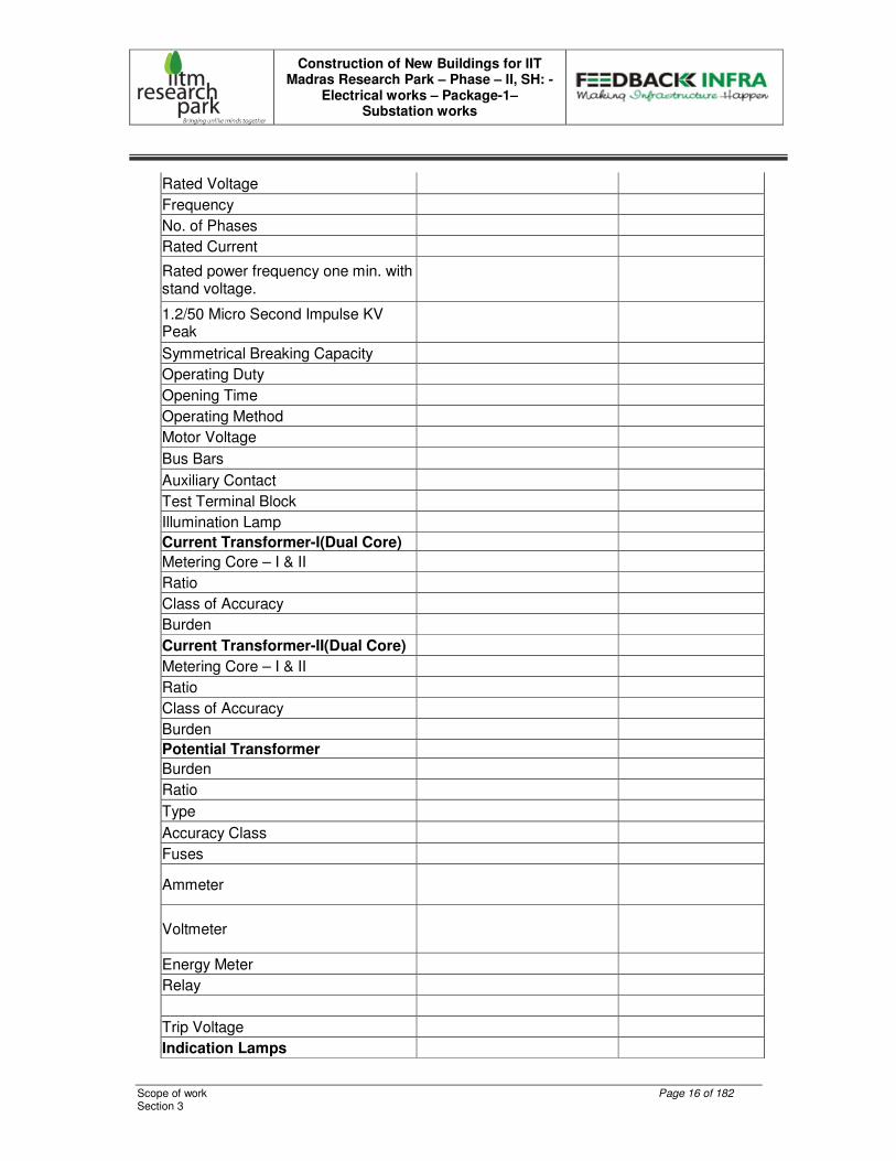
Rated Voltage
Frequency
No. of Phases
Rated Current
Rated power frequency one min. with stand voltage.
1.2/50 Micro Second Impulse KV Peak
Symmetrical Breaking Capacity
Operating Duty
Opening Time
Operating Method
Motor Voltage
Bus Bars
Auxiliary Contact
Test Terminal Block
Illumination Lamp
Current Transformer-I(Dual Core)
Metering Core – I & II
Ratio
Class of Accuracy
Burden
Current Transformer-II(Dual Core)
Metering Core – I & II
Ratio
Class of Accuracy
Burden
Potential Transformer
Burden
Ratio
Type
Accuracy Class
Fuses
Ammeter
Voltmeter
Energy Meter
Relay
Trip Voltage
Indication Lamps
Construction of New Buildings for IIT Madras Research Park – Phase – II, SH: -
Electrical works – Package-1– Substation works
Scope of work Page 17 of 182 Section 3
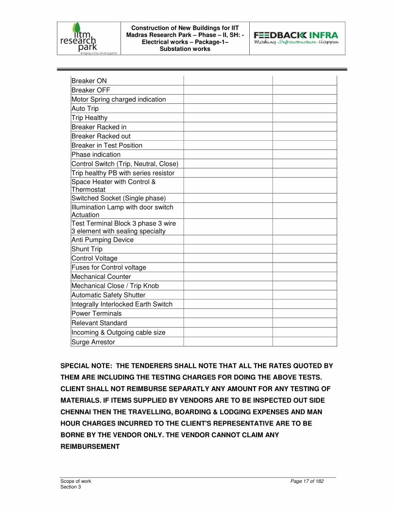
Breaker ON
Breaker OFF
Motor Spring charged indication
Auto Trip
Trip Healthy
Breaker Racked in
Breaker Racked out
Breaker in Test Position
Phase indication
Control Switch (Trip, Neutral, Close)
Trip healthy PB with series resistor
Space Heater with Control & Thermostat
Switched Socket (Single phase)
Illumination Lamp with door switch Actuation
Test Terminal Block 3 phase 3 wire 3 element with sealing specialty
Anti Pumping Device
Shunt Trip
Control Voltage
Fuses for Control voltage
Mechanical Counter
Mechanical Close / Trip Knob
Automatic Safety Shutter
Integrally Interlocked Earth Switch
Power Terminals
Relevant Standard
Incoming & Outgoing cable size
Surge Arrestor
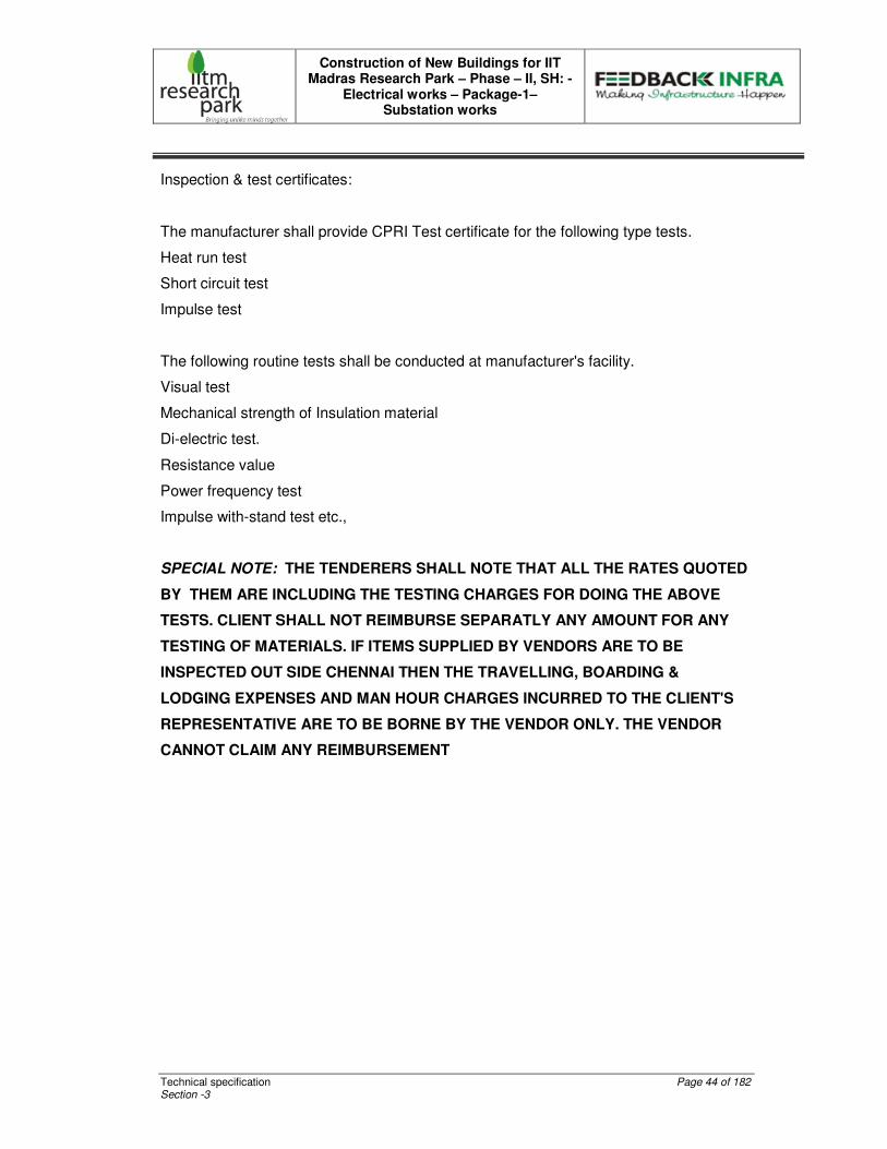
SPECIAL NOTE: THE TENDERERS SHALL NOTE THAT ALL THE RATES QUOTED BY
THEM ARE INCLUDING THE TESTING CHARGES FOR DOING THE ABOVE TESTS.
CLIENT SHALL NOT REIMBURSE SEPARATLY ANY AMOUNT FOR ANY TESTING OF
MATERIALS. IF ITEMS SUPPLIED BY VENDORS ARE TO BE INSPECTED OUT SIDE
CHENNAI THEN THE TRAVELLING, BOARDING & LODGING EXPENSES AND MAN
HOUR CHARGES INCURRED TO THE CLIENT'S REPRESENTATIVE ARE TO BE
BORNE BY THE VENDOR ONLY. THE VENDOR CANNOT CLAIM ANY
REIMBURSEMENT

Construction of New Buildings for IIT Madras Research Park – Phase – II, SH: -
Electrical works – Package-1– Substation works
Scope of work Page 18 of 182 Section 3
Construction of New Buildings for IIT Madras Research Park – Phase – II, SH: -
Electrical works – Package-1– Substation works
Technical specification Page 19 of 182 Section -3
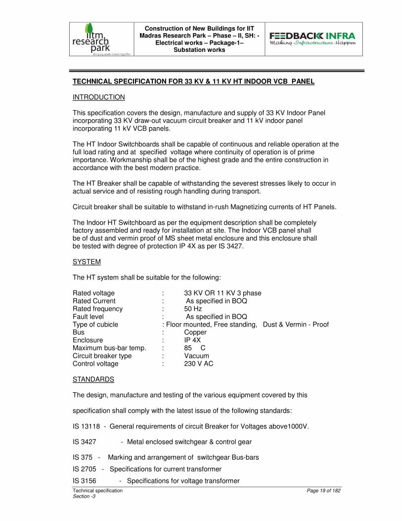
TECHNICAL SPECIFICATION FOR 33 KV & 11 KV HT INDOOR VCB PANEL
INTRODUCTION
This specification covers the design, manufacture and supply of 33 KV Indoor Panel incorporating 33 KV draw-out vacuum circuit breaker and 11 kV indoor panel incorporating 11 kV VCB panels. The HT Indoor Switchboards shall be capable of continuous and reliable operation at the full load rating and at specified voltage where continuity of operation is of prime importance. Workmanship shall be of the highest grade and the entire construction in accordance with the best modern practice. The HT Breaker shall be capable of withstanding the severest stresses likely to occur in actual service and of resisting rough handling during transport. Circuit breaker shall be suitable to withstand in-rush Magnetizing currents of HT Panels. The Indoor HT Switchboard as per the equipment description shall be completely factory assembled and ready for installation at site. The Indoor VCB panel shall be of dust and vermin proof of MS sheet metal enclosure and this enclosure shall be tested with degree of protection IP 4X as per IS 3427.
SYSTEM The HT system shall be suitable for the following:
Rated voltage : 33 KV OR 11 KV 3 phase Rated Current : As specified in BOQ Rated frequency : 50 Hz Fault level : As specified in BOQ Type of cubicle : Floor mounted, Free standing, Dust & Vermin - Proof Bus : Copper Enclosure : IP 4X Maximum bus-bar temp. : 85 � C Circuit breaker type : Vacuum Control voltage : 230 V AC
STANDARDS The design, manufacture and testing of the various equipment covered by this specification shall comply with the latest issue of the following standards:
IS 13118 - General requirements of circuit Breaker for Voltages above1000V.
IS 3427 - Metal enclosed switchgear & control gear
IS 375 - Marking and arrangement of switchgear Bus-bars
IS 2705 - Specifications for current transformer
IS 3156 - Specifications for voltage transformer
Construction of New Buildings for IIT Madras Research Park – Phase – II, SH: -
Electrical works – Package-1– Substation works
Technical specification Page 20 of 182 Section -3
IS 3231 - Electrical relays for power System Protection
IS 1248 - Electrical indicating instruments
IS 722 - Integrating meters
IS 6875 - Control switches and push buttons
IS 694 - PVC insulated cable with copper Conductor for Voltages up to 1100 V for
control wiring.
IS 732 - Electrical wiring installation
SPECIFIC REQUIREMENTS
CONSTRUCTION
The panel structure shall house the components with major weight of the equipment such as Circuit breaker, main horizontal bus bars and other auxiliary components, adequately supported without deformation or loss of alignment during transit & operation.
The Switch gears shall have necessary internal sheet metal barrier to form separate compartments for buses, instruments, relays, cable connections etc.
Adequate barriers shall permit the personnel to work safely within an empty compartment with the bus bars energized. Checking and removal of components shall be possible without disturbing the feeder. All auxiliary equipment shall be easily accessible to facilitate their operation and maintenance. It shall be possible to set all relays and measuring instruments without de-energizing the Switchgear.
All doors and openings shall be fitted with neoprene gaskets with fasteners designed to ensure proper compression of the gaskets. When covers are provided in place of doors, generous overlap shall be assured between sheet steel surfaces with closely spaced fasteners to prevent the entry of dust.
The panel shall have a rear cable chamber housing the cable and connections. The design shall ensure generous availability of space for easy installation and maintenance. Cabling and adequate safety for working in one section without coming into accidental contact with live part in an adjacent section.
The HT switchboard shall be constructed only with materials capable of withstanding the mechanical, electrical and thermal stresses, as well as the effects of humidity, which are likely to be encountered in normal service. All insulating materials used in construction of the equipment shall be non-hygroscopic materials, duly treated to withstand the effects of high humidity, high temperature and tropical ambient service conditions. Creepage distances shall comply with those specified in relevant standards.
The panel shall be provided with space heater to prevent condensation and the same shall be equipped with differential thermostat to automatically cut in and cut out the heater so as to maintain interior temperature, 5�C above the ambient and should have manual disconnect switch.
The total depth of the panel shall be adequate to cater for proper cabling space.
Construction of New Buildings for IIT Madras Research Park – Phase – II, SH: -
Electrical works – Package-1– Substation works
Technical specification Page 21 of 182 Section -3
Provision shall be made for permanently earthing the frames and other metal parts of the HT switchboard through a copper earth bus bar running throughout the full length of the switchboard at the bottom. Draw-out type switching units shall have sliding ground contact. It shall be possible to earth the switchboard at two independent points on either end, for connections to the external earthing network of the plant.
It shall be possible to extend the switchgear in either direction, whenever required. Ends of bus-bars shall be suitably drilled for this purpose.
Suitable eye bolt for lifting of panel shall be provided. On removing the eye bolts, the recess should be suitably covered, avoiding access into the panel.
BUSBARS
The bus-bars shall be epoxy moulded or PVC sleeved and made of high conductivity electrolytic grade copper. The current in all current carrying paths should not exceed 1.20A / sq mm. The bus bar chamber shall be totally maintenance free.
The switchboard shall comprise of 3 phase main bus-bars. The bus bar shall be of uniform cross-section throughout and shall be sized to continuously carry the rated current without exceeding the temperature rise of 40ºC over the maximum ambient temperature of 45ºC. Bus-bars shall be colour coded for easy identification of individual phases.
Bus bars shall be supported at regular intervals and both bus-bars and supports shall be adequately sized and braced to withstand short circuit level, without deformation. All bus supports shall be non-carbonizing material, resistant to acid alkalis and shall have non-hygroscopic characteristics.
For lengthy bus-bars suitable expansion joints shall be provided. Thermal design of the bus-bars shall be based on the installation of the switchgear in poorly ventilated condition.
Bus-bars shall be housed in a separate chamber, which shall be accessible for inspection only with special tools.
The rating of bus-bars shall be same as that of incomer breaker rating.
INSULATION LEVELS
The insulation level corresponding to the rated voltage are:
• Normal Voltage : 33 kV 11 kV
• Highest system voltage : 36kV 12 kV
• One minute Power Frequency : 70 kV 28 kV Withstand voltage
• 1.2/50 micro second impulse : 170 kV 75 kV
Construction of New Buildings for IIT Madras Research Park – Phase – II, SH: -
Electrical works – Package-1– Substation works
Technical specification Page 22 of 182 Section -3
Air insulated Busbar Clearance
• Phase to phase : 223 mm for 11 kV 356 mm for 33kV
• Phase to earth : 77 mm for 11kV 127 mm for 33 kV
CIRCUIT BREAKERS
(β) Circuit Breakers shall be triple pole, vacuum circuit breaker, and draw-out type.
(χ) The normal current rating of breakers should be at least 1.6 times the maximum loading of circuit it controls. The rupturing capacity of breaker should be at least 1.25 times the calculated fault level of bus-bars.
(δ) The breakers shall have motor operated spring charged mechanism with anti-pumping contactor. The control circuit shall be suitable for local as well as remote control.
(ε) The breaker sockets and plugs should be heavily silver-plated. It should have adequate auxiliary contacts required by plant control schematics plus 20% spare contacts for future use. Auxiliary contactors or relays should be used to multiply the contacts.
(φ) The operating mechanism shall be robust design with a minimum number of linkages to ensure maximum reliability. The operating mechanism shall be such that the breaker is at all times free to open immediately, when the trip coil is energized. It is to be ensured that all the three poles open/close in unison to avoid any eventuality of single-phasing operation.
(γ) The breaker shall have the distinct positions indicating:
(η) ‘Service’ Position : With main auxiliary contacts Connected.
(ι) ‘Test’ Position : With power contacts fully disconnected and control circuit contacts connected.
(ϕ) ‘Isolated’ Position : With both power and control circuit Contacts fully disconnected.
(κ) Earthing : While drawing-in the Breaker, earth shall Come into contact before the test Position. While drawing-out the Breaker, earth shall Disconnect after the test position
(λ) The circuit breaker can be closed only when it is in one of the three positions or when it is fully out of the panel.
Construction of New Buildings for IIT Madras Research Park – Phase – II, SH: -
Electrical works – Package-1– Substation works
Technical specification Page 23 of 182 Section -3
(µ) The breaker trolley shall remain inside the cubicle even in the draw-out position.
(ν) The trolley of the circuit breaker shall be so inter-locked that, it shall not be possible to isolate it from the connected position, or to plug it in from the isolated position with the breaker closed.
(ο) It shall not be possible to open the breaker compartment door unless the breakers drawn to the isolated position or test position.
(π) Inadvertent ‘pushing in’ of the draw-out circuit breaker in service position, with auxiliary circuit plug not in the position shall be prevented.
(θ) Automatic safety shutters shall be provided to ensure the inaccessibility of live parts after the breaker is drawn-out.
(ρ) The circuit breaker trolley shall be provided with a heavy-duty self-aligning earth contact, which shall make before and break after the main isolating contacts during insertion into and withdrawal from the service position of the breaker. Even in the isolated position, positive earthing contact should exist.
(σ) Circuit breakers of identical rating shall be interchangeable. EARTH SWITCHES Each breaker shall be provided with independent earth switch (make proof) to earth the cable side terminals. Optionally an earth trolley shall be provided for all the breakers.
CURRENT TRANSFORMERS
The current transformer shall be of cast resin insulated type of adequate capacity and proper characteristics on secondary, as specified. The current density should not be more than 1 amp/ sq mm. CTs shall withstand stresses originated from short circuit. They shall have ratios, output and accuracy as specified. They shall be mounted on the switchboard stationary part. The secondary leads of the CTs from all panels should be terminated on the front of the board on easily accessible shorting type terminal connectors so that operation and maintenance can be carried out when the panels are in service. CT’s shall be given the heat – run. CT Shall be of Dual core (Please refer to BOQ for details)
Construction of New Buildings for IIT Madras Research Park – Phase – II, SH: -
Electrical works – Package-1– Substation works
Technical specification Page 24 of 182 Section -3
POTENTIAL TRANSFORMER
The Potential Transformer shall be 200VA, 3Ph, Class 0.5 accuracy, 33KV/�3 / 110V/�3 cast resin insulated type. It shall be provided with HT/ LT HRC fuses with sealing arrangement. (Refer to BOQ for detailed specification) MEASURING INSTRUMENTS All measuring instruments shall be of flush mounting, Digital type and the size of the indicating instruments shall be of 96 x 96 Sq. mm.
Measuring meter shall be provided in the 33KV or 11 kV HT panel.
Control and selector switches shall be of CAM operated rotary switches The voltmeter selector switches shall be of 10A rating to measure the voltage between phases with “OFF”. The ammeter selector switches shall be of 10A rating to measure the phase current through CTs INDICATING LAMPS
Indicating lamps shall be of LED type, low watt consumption, provided with series resistor where necessary and with translucent lamp covers. Bulbs and lenses shall be easily replaceable from the front. Following Indicating Lamps are required on the panel having lens colours as detailed below :
1. RYB Indication Lamps : RED, YELLOW, BLUE
2. Breaker ON : RED
3. Breaker OFF : GREEN
4. Breaker racked IN : RED
5. Breaker racked OUT : GREEN
6. Auto Trip : AMBER
7. Trip circuit healthy : WHITE
8. Spring charged : BLUE
9. Test position : YELLOW RELAYS All protective relays shall be of numerical type, suitable for flush mounting and fitted with dust tight covers. All relays shall be mounted on the front of the panel and shall be specified as per requirement. The current and the voltage coils shall be provided as specified. All relays shall have provision to indicate operation. It shall be possible to reset the same without opening the relay case. All tripping relays shall be suitable to operate on the specified voltage.

Construction of New Buildings for IIT Madras Research Park – Phase – II, SH: -
Electrical works – Package-1– Substation works
Technical specification Page 25 of 182 Section -3
Three Over current & one Earth fault relay with instantaneous trip shall be provided with following settings O/L 50-200% and E/F 20-80% relay.
CONTROL SWITCHES AND PUSH BUTTONS Control switches shall be of the heavy-duty rotary type with nameplates duly marked to show the operation. They shall be semi-flush mounting with only the front plate and operating handle projecting. Control switch shall be provided for Trip & Close the VCB with Neutral position. A Push button shall be available to check the healthiness of trip circuit. SURGE ARRESTOR
The HT Indoor VCB Panel shall be provided with transient Voltage Surge Arrestors to protect the equipments from Surges, which are created due to lightning or switching action.
AUXILIARY SWITCHES
Each circuit breaker shall be provided with auxiliary switches to interrupt the supply to the Closing mechanism and complete the trip circuit, when the circuit breaker is in the ‘Closed’ position and to cover all the necessary indication, interlocking and control facilities. All secondary connection between the fixed and moving portions of circuit breaker equipment shall be by means of plug and socket connections, arranged so as to eliminate positively any false indication when the moving portion is racked in to the service location. Each circuit breaker shall be provided with 4 NO + 4 NC auxiliary contacts as spare in addition to the other functional requirements.
INTERNAL WIRING Internal wiring and inter-panel wiring for all circuit shall be carried out with 1100/650V grade, single core, multi stranded, PVC insulated copper wire of minimum 2.5 sq. mm for CT and other control circuit. The wiring shall be neatly bunched, adequately supported and properly routed and terminated in the respective terminals with suitable lugs. There shall not be more than two wires connected at a terminal. Wires shall be identified by numbered ferrules at each end. The ferrules shall be of ring type and non-deteriorating material. All control circuits shall have HRC fuses mounted in front of the panel and shall be easily accessible.

Construction of New Buildings for IIT Madras Research Park – Phase – II, SH: -
Electrical works – Package-1– Substation works
Technical specification Page 26 of 182 Section -3
TERMINAL BLOCKS AND TEST BLOCKS Terminal blocks & Test blocks for the LT connections shall be of 650 V grade, stud type and of adequate current rating. The insulating barriers shall be provided between adjacent terminals. Provision shall be made for label inscription on terminal block. Cables should never be terminated directly on components. Provision shall be made for CT terminals shorting links, remote ON/OFF pushbutton, remote ON/OFF indication and remote Ammeter. 20% spare terminals shall be provided on each terminal block.
CABLE TERMINATION Ample space for connection of these cables shall be provided at the rear of the Switchboard. The cable termination arrangement shall be of adequate size and design to receive the required number of cables as specified. Proper cable clamping arrangements shall be provided. Detachable gland plate of 3 mm thickness shall be provided for the cable entry into the panel. Sufficient space shall be provided to avoid sharp bending and facilitate easy connection. Suitable shrouds shall be provided to prevent accidental contact with live outgoing terminations of other feeders while carrying out maintenance on one feeder.
LABLES Name plates of approved design shall be provided to represent circuit designation for each feeder. Material for nameplates shall be engraved Aluminium Sheet with white background with black letters and firmly secured with fasteners. PAINTING All metal surfaces shall be chemically cleaned, degreased and pickled in acid to produce a smooth clean surface, free of scale, grease and rust. After cleaning, phosphating and passivation treatment, the surface shall be given two coats of zinc rich epoxy primer and baked in the oven. After primer, it shall be given powder coated paint shade of RAL 7032 in light gray Sufficient quantity of touch up paint shall be furnished for application at site.
TESTS
Pre-commissioning Checks and Tests shall be conducted at site by you at free of cost and certificate shall be furnished.
VISUAL TESTS
5. Corrosion test
6. Paint inspection
7. Physical verification check
8. Rubber gasket test.
Construction of New Buildings for IIT Madras Research Park – Phase – II, SH: -
Electrical works – Package-1– Substation works
Technical specification Page 27 of 182 Section -3
9. Megger Test. The following routines tests shall be conducted on the 33 KV switch board as per the relevant Indian Standards at the time of inspection.
ROUTINE TESTS
The HT Panel Board shall be tested for routine tests as per the relevant Indian Standards.
10. Milli volt drop test
11. DC resistance test
12. Contact resistance test
13. HV test for required voltage level for 1 minute
14. Endurance test (20 opening & closing operations)
15. Control wiring tested with 2.5 KV applied
16. Insulation Resistance test value before and after tests
17. (500V Megger for control wiring & 5KV Megger for HV)
18. Milli volt drop test on Rigid and expansion joints.
19. Temperature Rise Test.
20.20.20.20. Secondary Injection Test for relays and instruments. INSPECTION
Stage 1 Inspection : During Assembly of Panel Stage 2 Inspection : Before Dispatch The readiness should be informed at least fifteen days before the proposed date of Inspection.
COMMISSIONING
The supplier shall render the service of his supervisor during the Installation and commissioning of the panels by other agency at free of cost. The quoted price shall be inclusive of all necessary commissioning spares. DRAWINGS AND MANUALS The following drawings and manuals shall be submitted in six sets, for approval: General arrangement of circuit breaker showing
1. Overall dimensions
2. Terminal locations
3. Total weight
4. Operating Manuals
5. Bill of materials
6. Foundation details
Construction of New Buildings for IIT Madras Research Park – Phase – II, SH: -
Electrical works – Package-1– Substation works
Technical specification Page 28 of 182 Section -3
SPARES AND TOOLS The commissioning and maintenance spares required for installing the HT Switch board shall be quoted separately. The tools required for the HT Switch boards also listed and quoted separately. SPECIAL NOTE: THE TENDERERS SHALL NOTE THAT ALL THE RATES QUOTED
BY THEM ARE INCLUDING THE TESTING CHARGES FOR DOING THE ABOVE
TESTS. CLIENT SHALL NOT REIMBURSE SEPARATLY ANY AMOUNT FOR ANY
TESTING OF MATERIALS. IF ITEMS SUPPLIED BY VENDORS ARE TO BE
INSPECTED OUT SIDE CHENNAI THEN THE TRAVELLING, BOARDING & LODGING
EXPENSES AND MAN HOUR CHARGES INCURRED TO THE CLIENT'S
REPRESENTATIVE ARE TO BE BORNE BY THE VENDOR ONLY. THE VENDOR
CANNOT CLAIM ANY REIMBURSEMENT
Construction of New Buildings for IIT Madras Research Park – Phase – II, SH: -
Electrical works – Package-1– Substation works
Technical specification Page 29 of 182 Section -3
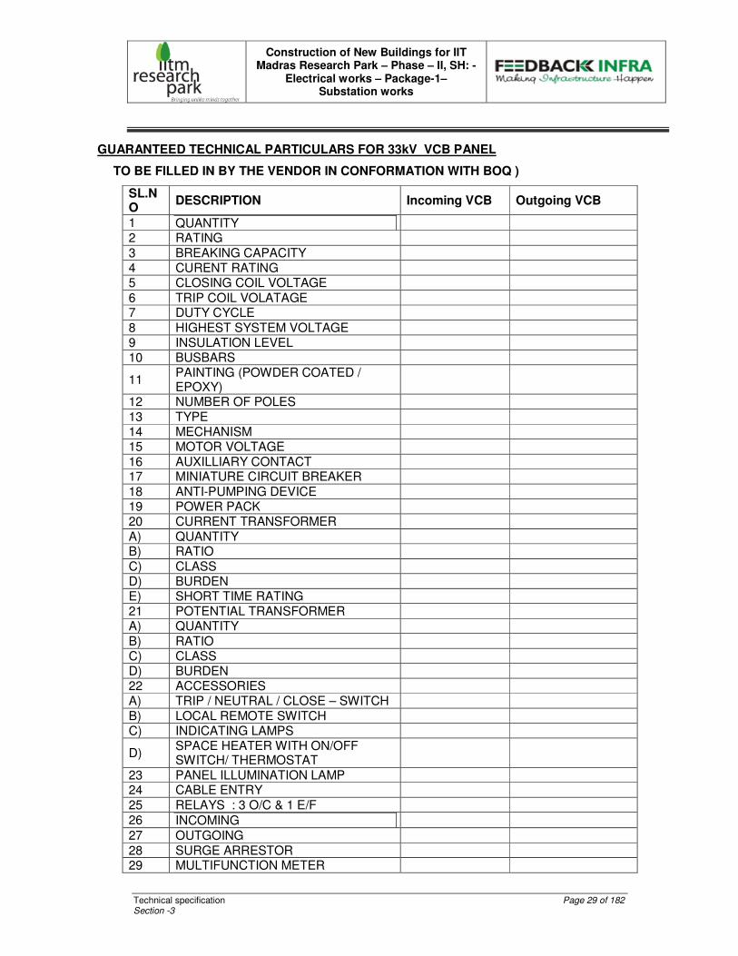
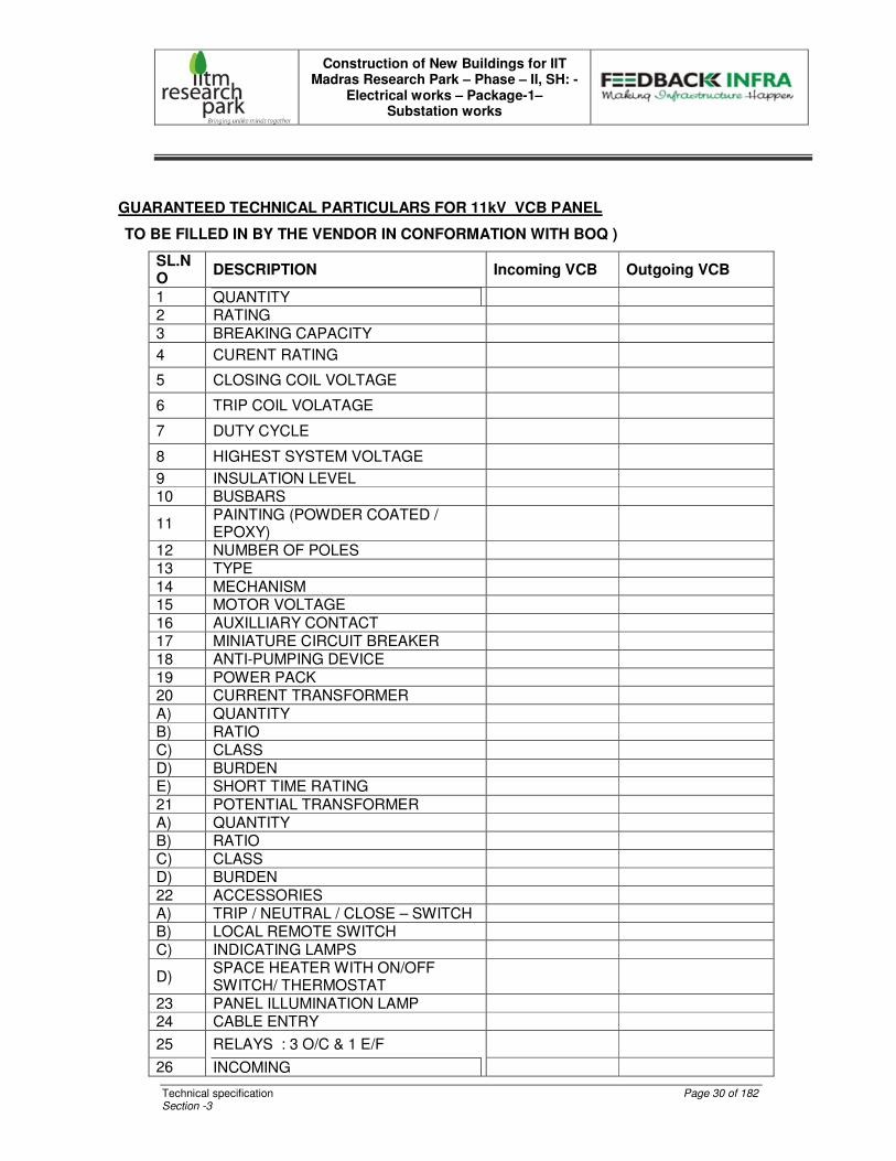
GUARANTEED TECHNICAL PARTICULARS FOR 33kV VCB PANEL
TO BE FILLED IN BY THE VENDOR IN CONFORMATION WITH BOQ )
SL.NO
DESCRIPTION Incoming VCB Outgoing VCB
1 QUANTITY
2 RATING
3 BREAKING CAPACITY 4 CURENT RATING 5 CLOSING COIL VOLTAGE
6 TRIP COIL VOLATAGE 7 DUTY CYCLE
8 HIGHEST SYSTEM VOLTAGE 9 INSULATION LEVEL 10 BUSBARS
11 PAINTING (POWDER COATED / EPOXY)
12 NUMBER OF POLES
13 TYPE 14 MECHANISM 15 MOTOR VOLTAGE
16 AUXILLIARY CONTACT 17 MINIATURE CIRCUIT BREAKER
18 ANTI-PUMPING DEVICE 19 POWER PACK 20 CURRENT TRANSFORMER
A) QUANTITY B) RATIO
C) CLASS D) BURDEN E) SHORT TIME RATING 21 POTENTIAL TRANSFORMER A) QUANTITY
B) RATIO C) CLASS D) BURDEN 22 ACCESSORIES A) TRIP / NEUTRAL / CLOSE – SWITCH
B) LOCAL REMOTE SWITCH C) INDICATING LAMPS
D) SPACE HEATER WITH ON/OFF SWITCH/ THERMOSTAT
23 PANEL ILLUMINATION LAMP 24 CABLE ENTRY
25 RELAYS : 3 O/C & 1 E/F
26 INCOMING
27 OUTGOING
28 SURGE ARRESTOR 29 MULTIFUNCTION METER
Construction of New Buildings for IIT Madras Research Park – Phase – II, SH: -
Electrical works – Package-1– Substation works
Technical specification Page 30 of 182 Section -3
GUARANTEED TECHNICAL PARTICULARS FOR 11kV VCB PANEL
TO BE FILLED IN BY THE VENDOR IN CONFORMATION WITH BOQ )
SL.NO
DESCRIPTION Incoming VCB Outgoing VCB
1 QUANTITY
2 RATING
3 BREAKING CAPACITY
4 CURENT RATING
5 CLOSING COIL VOLTAGE
6 TRIP COIL VOLATAGE
7 DUTY CYCLE
8 HIGHEST SYSTEM VOLTAGE
9 INSULATION LEVEL 10 BUSBARS
11 PAINTING (POWDER COATED / EPOXY)
12 NUMBER OF POLES 13 TYPE
14 MECHANISM 15 MOTOR VOLTAGE
16 AUXILLIARY CONTACT 17 MINIATURE CIRCUIT BREAKER 18 ANTI-PUMPING DEVICE
19 POWER PACK 20 CURRENT TRANSFORMER
A) QUANTITY B) RATIO C) CLASS
D) BURDEN E) SHORT TIME RATING
21 POTENTIAL TRANSFORMER A) QUANTITY B) RATIO C) CLASS D) BURDEN
22 ACCESSORIES A) TRIP / NEUTRAL / CLOSE – SWITCH B) LOCAL REMOTE SWITCH C) INDICATING LAMPS
D) SPACE HEATER WITH ON/OFF SWITCH/ THERMOSTAT
23 PANEL ILLUMINATION LAMP 24 CABLE ENTRY
25 RELAYS : 3 O/C & 1 E/F
26 INCOMING
Construction of New Buildings for IIT Madras Research Park – Phase – II, SH: -
Electrical works – Package-1– Substation works
Technical specification Page 31 of 182 Section -3
27 OUTGOING
28 SURGE ARRESTOR
29 MULTIFUNCTION METER
Construction of New Buildings for IIT Madras Research Park – Phase – II, SH: -
Electrical works – Package-1– Substation works
Technical specification Page 32 of 182 Section -3
TECHNICAL SPECIFICATION FOR 33 KV HT INDOOR RMG PANEL
INTRODUCTION
This specification covers the design, manufacture and supply of 33 KV RMG incorporating 33 KV draw-out vacuum circuit breaker and Load break Switches. The Ring Main Gear shall be of INDOOR type and rated for a fault level of 1500MVA, 26.2 KA, continuous current and shall be suitable for operation on 3 phase 3 wire 33 KV earthed System. The subject RMG is to be supplied in accordance with IS regulations and should satisfy the TNEB requirements. The Load Break Switch, Vacuum Circuit Breaker and all accessories in the RMG shall be as per the detailed specification for each of them and suitable for operation for the system voltage indicated. It shall be capable of continuous and reliable operation at the full load rating specified where continuity of operation is of prime importance. Workmanship shall be of the highest grade and the entire construction in accordance with the best modern practice. The RMG shall be capable of withstanding the severest stresses likely to occur in actual service and of resisting rough handling during transport. Circuit breaker shall be suitable to withstand in-rush Magnetizing currents of HT Panels. The INDOOR RMG as per the equipment description shall be completely factory assembled and ready for installation at site. The INDOOR RMG shall be of dust and vermin proof of MS sheet metal enclosure and this enclosure shall be tested with degree of protection IP 55 as per IS 3427. EQUIPMENT DESCRIPTION The Ring Main Gear shall be of INDOOR type and shall consists of 2Nos. 33 KV, short time rated (AS PER BOQ), Air Break / Load Break Switch with suitably interlocked earth switch, front operated, spring assisted, manual closing mechanism for controlling the incoming supply and 1 no 33 KV, horizontal draw out horizontal isolation Vacuum Circuit Breaker fitted with motor operated spring charging mechanism, for controlling the outgoing supply.

Construction of New Buildings for IIT Madras Research Park – Phase – II, SH: -
Electrical works – Package-1– Substation works
Technical specification Page 33 of 182 Section -3
SYSTEM The system shall be suitable for the following:
Rated voltage : 33 KV, 3 phase Rated Current : Refer BOQ Rated frequency : 50 Hz Fault level : Refer BOQ Type of cubicle : Floor mounted, free standing,
Dust & Vermin - Proof Bus : Copper Enclosure : IP 55 Maximum bus-bar temp. : 85 � C Circuit breaker type : Vacuum Control voltage : 230 V AC
STANDARDS The design, manufacture and testing of the various equipment covered by this specification shall comply with the latest issue of the following standards:
IS 13118 - General requirements of circuit Breaker for voltages above 1000V.
IS 3427 - Metal enclosed switchgear & control gear
IS 375 - Marking and arrangement of switchgear Bus-bars
IS 2705 - Specifications for current transformer
IS 3156 - Specifications for voltage transformer
IS 3231 - Electrical relays for power System Protection
IS 1248 - Electrical indicating instruments
IS 722 - Integrating meters
IS 6875 - Control switches and push buttons
IS 694 - PVC insulated cable with copper Conductor for Voltages up to 1100 V for
control wiring.
IS 7098(Latest) - HT XLPE cable

Construction of New Buildings for IIT Madras Research Park – Phase – II, SH: -
Electrical works – Package-1– Substation works
Technical specification Page 34 of 182 Section -3
SPECIFIC REQUIREMENTS
CONSTRUCTION
The panel structure shall house the components with major weight of the equipment such as Circuit breaker, main horizontal bus bars and other auxiliary components, adequately supported without deformation or loss of alignment during transit & operation.
The Switch gears shall have necessary internal sheet metal barrier to form separate compartments for buses, instruments, relays, cable connections etc. Adequate barriers shall permit the personnel to work safely within an empty compartment with the bus bars energized. Checking and removal of components shall be possible without disturbing the feeder. All auxiliary equipment shall be easily accessible to facilitate their operation and maintenance. It shall be possible to set all relays and measuring instruments without de energizing the Switchgear.
All doors and openings shall be fitted with neoprene gaskets with fasteners designed to ensure proper compression of the gaskets. When covers are provided in place of doors, generous overlap shall be assured between sheet steel surfaces with closely spaced fasteners to prevent the entry of dust.
The panel shall have a rear cable chamber housing the cable and connections. The design shall ensure generous availability of space for easy installation and maintenance. Cabling and adequate safety for working in one section without coming into accidental contact with live part in an adjacent section.
The HT switchboard shall be constructed only with materials capable of withstanding the mechanical, electrical and thermal stresses, as well as the effects of humidity, which are likely to be encountered in normal service. All insulating materials used in construction of the equipment shall be non-hygroscopic materials, duly treated to withstand the effects of high humidity, high temperature and tropical ambient service conditions. Creepage distances shall comply with those specified in relevant standards.
The panel shall be provided with space heater to prevent condensation and the same shall be equipped with differential thermostat to automatically cut in and cut out the heater so as to maintain interior temperature, 5�C above the ambient and should have manual disconnect switch.
The total depth of the panel shall be adequate to cater for proper cabling space.
Provision shall be made for permanently earthing the frames and other metal parts of the switchboard through a copper earth bus bar running throughout the full length of the switchboard at the bottom. Draw-out type switching units shall have sliding ground contact. It shall be possible to earth the switchboard at two independent points on either end, for connections to the external earthing network of the plant.
It shall be possible to extend the switchgear in either direction, whenever required. Ends of bus-bars shall be suitably drilled for this purpose.
Construction of New Buildings for IIT Madras Research Park – Phase – II, SH: -
Electrical works – Package-1– Substation works
Technical specification Page 35 of 182 Section -3
Suitable eye bolt for lifting of panel shall be provided. On removing the eye bolts, the recess should be suitably covered, avoiding access into the panel.
BUSBARS
The bus-bars shall be epoxy moulded or PVC sleeved and made of high conductivity electrolytic grade Copper. The current in all current carrying paths should not exceed 1.2 A / sq mm.
The bus bar chamber shall be totally maintenance free.
The switchboard shall comprise of 3 phase main bus-bars. The bus bar shall be of uniform cross-section throughout and shall be sized to continuously carry the rated current without exceeding the temperature rise of 40ºC over the maximum ambient temperature of 45ºC. Bus-bars shall be colour coded for easy identification of individual phases.
Bus bars shall be supported at regular intervals and both bus-bars and supports shall be adequately sized and braced to withstand short circuit level, without deformation. All bus supports shall be non-carbonizing material, resistant to acid alkalies and shall have non-hygroscopic characteristics.
For lengthy bus-bars suitable expansion joints shall be provided. Thermal design of the bus-bars shall be based on the installation of the switchgear in poorly ventilated condition.
Bus-bars shall be housed in a separate chamber, which shall be accessible for inspection only with special tools.
The rating of bus-bars shall be same as that of incomer breaker rating.
INSULATION LEVELS
The insulation level corresponding to the rated voltage are:
• Normal Voltage : 33 kV
• Highest system voltage : 36kV
• One minute Power Frequency : 70 kV RMS
• Withstand voltage
• 1.2/50 micro second impulse : 170 kV Peak
Air insulated Busbar Minimum Clearance
• Phase to phase : 223 mm
• Phase to earth : 77 mm
AIRBREAK / LOAD BREAK SWITCH PANEL (2Nos.) The Air break / Load Break switch panel shall consist of the following:
One number 33KV, 630 Amps, 26.2 KA rated, HT Air Break / Load break switch suitably interlocked with earth switch. It shall be with front operated
Construction of New Buildings for IIT Madras Research Park – Phase – II, SH: -
Electrical works – Package-1– Substation works
Technical specification Page 36 of 182 Section -3
spring assisted manual mechanism & with 2No + 2Nc Auxiliary contacts & operating handle. ON /OFF indication Lamps : 2Nos. 630 A Copper bus-bars : 1Set Space Heater with thermostat & switch control : 1Set Lamp Holder with Door Switch & lamp : 1Set Provision to receive the incoming 33 KV, XLPE cable at Bottom. The above Load Break switch panel shall be trunked, one on either side of the VCB panel. The Load Break Switch shall be suitable for panel mounting type. It shall be of simple and compact construction with suitable graded MOULDED EPOXY support, double switch-blades and forged contacts with arc quenching chamber, locking pin and loop less current path. The main frame shall be of welded steel and contacts shall be mounted in Epoxy insulators. The upper fixed contact shall house the arc quenching chamber and connecting terminal. It shall be equipped with spring assisted mechanism due to which constant speed can be achieved during opening & closing and shall be provided with stored energy tripping device. They shall be built as per IS 9920 / IEC 265. They shall be capable of make and break at the normal rated current and shall also make the short circuit current earthed, without endangering the operator Fully rated Earth switch interlocked with Load Break Switch shall be provided as per the requirement of TNEB as a Factory Fitted Accessory.
Construction of New Buildings for IIT Madras Research Park – Phase – II, SH: -
Electrical works – Package-1– Substation works
Technical specification Page 37 of 182 Section -3
TECHNICAL SPECIFICATION OF HT CABLES SCOPE
Supply, installation, storing, laying, fixing, jointing, terminating, testing and
commissioning of High Voltage XLPE insulated Armoured Aluminium Conductor cores
laid-up with Polypropylene central filler and tape, extruded PVC inner sheathed, GI
wire/strip armoured and PVC outer sheathed overall confirming to IS 7098 part I 1988
with latest amendments and specifications given below, laid in built up trenches, directly
buried underground, on cable trays, in pipes, clamped directly to wall or Structures.
Cable shall be capable of satisfactory performance when laid on trays, trenches,
conduits, ducts and when directly buried in the ground.
Cables shall be capable of operating satisfactorily under a power supply system voltage
variation of +10%, frequency variation +5%, and combined voltage and frequency
variation of +10%.
Cables shall normally be laid under the following conditions:
21. In air : Ambient temperature of 45�.C
22. In ground : Ground temperature of 35� C
23. Depth of laying in ground : 900mm(11KV)
: 1050mm (22&33KV)
24. In conduits : Space factor of not more than 60%
25. In trays : Single layer, touching each other
26. The maximum conductor temperature for operation under
Normal rated current carrying conditions and under short
Circuit conditions are as follows:
Construction of New Buildings for IIT Madras Research Park – Phase – II, SH: -
Electrical works – Package-1– Substation works
Technical specification Page 38 of 182 Section -3
Maximum conductor temperature & Standard Installation Conditions
(τ) Maximum Conductor temperature at continuous load 90�C
(υ) Ambient Air temperature 45�C
(ϖ) Ground Temperature 30�C
(ω) Thermal resistivity of XLPE 350�C cm/W
(ξ) Thermal resistivity of PVC 70�C cm/W
(ψ) XLPE cables shall be rated to carry the specified fault current for specific
duration.
(ζ) Method of laying - Multi core cables laid singly Single core cables laid in trefoil
Touching / in flat formation XLPE Construction
7. Voltage grade :11KV/33 kV
8. Conductor :Well compacted Aluminium
9. Conductor screen : This shall be extruded shield in the same operation as the
insulation. The semiconductor polymer shall be cross
linked.
10. Insulation : Shall be cross-linked polyethylene.
11. Laying up : The core shall be laid up with Polypropylene filling and
tape.
12. Inner sheath :Shall be extruded PVC
13. Armour :Single galvanized steel wire/strip armour
14. The cable outer sheath shall be extruded ST-2 type PVC.
15. General: The cable shall withstand all mechanical and
16. Thermal stresses under steady state and transient
17. Operating conditions.
18. Operation and Maintenance Manuals
Conductor
The conductor consists of annealed Copper or Aluminium wires compacted having a
smooth circular or the required shape as per IS: 8130-84. (IEC 60228 / BS 6360)
Construction of New Buildings for IIT Madras Research Park – Phase – II, SH: -
Electrical works – Package-1– Substation works
Technical specification Page 39 of 182 Section -3
Conductor screen
The conductor screen consists of a layer of smooth black extruded semi-conducting
XLPE compound firmly bonded with the insulation. This eliminates electrical discharges
at the interface between conductor and insulation.
Insulation
The insulation consists of super clean XLPE compound. The extrusion process is
conducted in clinically clean environment. The insulation thickness conforms to IS:
7098./ IS 5831
Insulation screen
The screen consists of smooth black semi conducting XLPE compound firmly bonded
with a smooth interface with the insulation. Also the conductor screen, insulation and
insulation screen are extruded simultaneously in Dry cure process.
Conductor screen
Conductor screen shall be extruded semi conducting compound as per IS 7098 part -2
Moisture barrier
To make the cable longitudinally watertight a semi conducting tape is applied over the
core to prevent water penetration in the cable. The tape is of non-woven material which
has non-biodegradable characteristics.
Copper wire screen
Copper wires are applied to carry the necessary earth fault current. A counter open helix
copper tape is provided over the copper wires.
Poly – Aluminium foil
Aluminium foil coated with polyethylene used longitudinally as a moisture barrier is
designed for making cable lighter in weight.
Inner sheath
After the above process cables are to be provided with inner sheath with high quality
PVC which shall act as bedding for steel wire/strip armour. Filler cords are to provided to
maintain the circularity of cables
Construction of New Buildings for IIT Madras Research Park – Phase – II, SH: -
Electrical works – Package-1– Substation works
Technical specification Page 40 of 182 Section -3
Armouring
Mechanical protection to the cable is provided with armouring. Armour shall be of GI
wire or strip as specified. For single core cables the armour shall be aluminium ( if
specified) or GI. Armouring shall conform to IS 3975 specifiications
Outer sheathing
The jacketing material consists of extruded black PVC or high-density polyethylene
(HDPE). A graphite coat is provided over the outer surface of the sheath. In specific
cases with ST2 compound as spefiied.
General purpose sheathing compound ST1
Heat resistant Compund ST2
IS specification for sheathing is IS 5831.Cables are to be sequentially marked for length
at every meter throughout its length.
The following letter designations shall be used to specify type of cables:
A - Aluminium conductor
Y - PVC insulation or PVC sheath or overall
PVC Jacket (over armour)
F - GI Flat steel (strip) armour
W - Galvanized round steel wire armour
If the conductor is copper then A is not mentioned
Letter designations for cables shall be indicated in the following order:
Conductor size
Insulation
Sheath
Armour
Overall jacket
Construction of New Buildings for IIT Madras Research Park – Phase – II, SH: -
Electrical works – Package-1– Substation works
Technical specification Page 41 of 182 Section -3
Testing of Cables TESTS
10. Cable Insulation Tests shall be conducted between phases and between phase and
earth for each length of cable, before and after jointing. As such all phase cables
may be checked before being laid for above tests. On completion of cable laying
work, the following tests shall be conducted in the presence of the
Consultant/Employer.
Construction tests
Test for conductor and compaction.
Test for aluminium conductor:
7. Tensile test
8. Wrapping test
9. Annealing test
10. Resistance test for both copper and aluminium
• Test for eccentricity of insulation.
• Test for thickness of insulation
• Test for laying up along with Polypropylene tape and fillers.
• Virgin material test for PVC insulation.
• Test for thickness of inner sheath
• Test for armouring and armour coverage which should be more than 95% Test for thickness of outer sheath
• Insulation Resistance Test (sectional and overall)
• Continuity resistance test.
• Sheathing continuity test.
• Cable size, sequential and manufacturers identification marking on the outer sheath.
Construction of New Buildings for IIT Madras Research Park – Phase – II, SH: -
Electrical works – Package-1– Substation works
Technical specification Page 42 of 182 Section -3
• Earth test.
All tests shall be carried out in accordance with relevant Indian Standard Code of Practice and Local Electricity Rules. The Contractor shall provide necessary instruments, equipment and labour for conducting the above tests and shall bear all expenses in connection with such tests. All tests shall be carried out in the presence of the Consultant/Employer.
CABLING SYSTEM
GENERAL
The cabling system covers the design as per relevant national / international standards.
It shall be responsibility of contractor to work out a detailed layout for the cable system.
The layout drawing shall be furnished for the approval of Engineer before
commencement of installation including cable trays, cable racks, accessories, tray
supports, conduit etc.
CABLE LAYOUT
The following points shall be noted while planning cabling system for the plant
Inside the building either cable tray or cable trench shall be planned as per cabling
requirement.
Laying of Cables
Cables shall be laid as per the specifications given below:
Cables - Outdoor Trenches
Cables shall be laid in outdoor trenches wherever called for. The depth of the trenches shall not be less than 900 mm (11KV) and 1050mm (22&33KV), below the final ground level. The width of the trenches shall not be less than 500 mm. Suitable de-rating factors shall be applied depending upon laying method and spacing. The trenches shall be cut square with vertical sidewalls and with uniform depth. Suitable shoring and propping may be done to avoid caving-in of trench walls. The floor of the trench shall be rammed level. The cables shall be laid in trenches over rollers placed inside the trench.
The cable drums shall be laid unrolled in the direction of the arrow marked on the drum for unrolling.
Construction of New Buildings for IIT Madras Research Park – Phase – II, SH: -
Electrical works – Package-1– Substation works
Technical specification Page 43 of 182 Section -3
Wherever cables are bent, the minimum-bending radius shall not be less than 12
times the diameter of the cable. After the cable is laid and straightened, it shall be
covered with 150 mm thick layer of sand. The cable shall then be lifted and placed
over the sand cushion. Over this, 450 mm thick layer of sand shall be covered and a
course of cable protection tiles or burnt brick shall be provided to cover the cables by
50 mm on either side. Remaining trench shall be backfilled with earth and
consolidated as original. Cables shall be laid in hume pipes/stoneware pipes at all
road crossings and in GI pipe at the wall entries. Cable route markers to be provided
as per standards
Excess debris shall be removed from site at free of cost
Joining Cables
All cable joints shall be made in suitable, approved cable joint kits, and the filling in
of compound shall be done in accordance with manufacturers’ instructions and in an
approved manner. All straight through joints shall be done in epoxy mould boxes
with epoxy resin.
All cables shall be jointed colour- to- colour (should not be different colours); tested for continuity and insulation resistance before jointing. The seals of cables must not be removed until preparations for jointing are completed. Joints shall be commenced and finished on the same day. During the time of joining the cables, sufficient protection from the weather shall be ensured. Joints shall be made by means of suitable solder for conductors, the conductors being firmly butted into the connections or thimbles or ferrules and the whole soldered with proper solder and soldering flux. The conductors shall be efficiently insulated with high voltage insulating tape and by using of spreaders of approved size and pattern. The joints shall be completely topped up with epoxy compound so as to ensure that the box is properly filled.
The Cable entries through pipes from outside to inside the building shall run in GI
pipes and shall be sealed water tight with approved type of sealant to avoid water
entering the building.
Construction of New Buildings for IIT Madras Research Park – Phase – II, SH: -
Electrical works – Package-1– Substation works
Technical specification Page 44 of 182 Section -3
Inspection & test certificates:
The manufacturer shall provide CPRI Test certificate for the following type tests.
Heat run test
Short circuit test
Impulse test
The following routine tests shall be conducted at manufacturer's facility.
Visual test
Mechanical strength of Insulation material
Di-electric test.
Resistance value
Power frequency test
Impulse with-stand test etc.,
SPECIAL NOTE: THE TENDERERS SHALL NOTE THAT ALL THE RATES QUOTED
BY THEM ARE INCLUDING THE TESTING CHARGES FOR DOING THE ABOVE
TESTS. CLIENT SHALL NOT REIMBURSE SEPARATLY ANY AMOUNT FOR ANY
TESTING OF MATERIALS. IF ITEMS SUPPLIED BY VENDORS ARE TO BE
INSPECTED OUT SIDE CHENNAI THEN THE TRAVELLING, BOARDING &
LODGING EXPENSES AND MAN HOUR CHARGES INCURRED TO THE CLIENT'S
REPRESENTATIVE ARE TO BE BORNE BY THE VENDOR ONLY. THE VENDOR
CANNOT CLAIM ANY REIMBURSEMENT
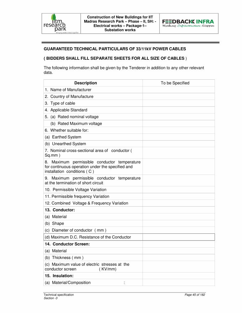
Construction of New Buildings for IIT Madras Research Park – Phase – II, SH: -
Electrical works – Package-1– Substation works
Technical specification Page 45 of 182 Section -3
GUARANTEED TECHNICAL PARTICULARS OF 33/11kV POWER CABLES ( BIDDERS SHALL FILL SEPARATE SHEETS FOR ALL SIZE OF CABLES ) The following information shall be given by the Tenderer in addition to any other relevant data.
Description To be Specified
1. Name of Manufacturer
2. Country of Manufacture
3. Type of cable
4. Applicable Standard
5. (a) Rated nominal voltage
(b) Rated Maximum voltage
6. Whether suitable for:
(a) Earthed System
(b) Unearthed System
7. Nominal cross-sectional area of conductor ( Sq.mm )
8. Maximum permissible conductor temperature for continuous operation under the specified and installation conditions ( C )
9. Maximum permissible conductor temperature at the termination of short circuit
10. Permissible Voltage Variation
11. Permissible frequency Variation
12. Combined Voltage & Frequency Variation
13. Conductor:
(a) Material
(b) Shape
(c) Diameter of conductor ( mm )
(d) Maximum D.C. Resistance of the Conductor
14. Conductor Screen:
(a) Material
(b) Thickness ( mm )
(c) Maximum value of electric stresses at the conductor screen ( KV/mm)
15. Insulation:
(a) Material/Composition :
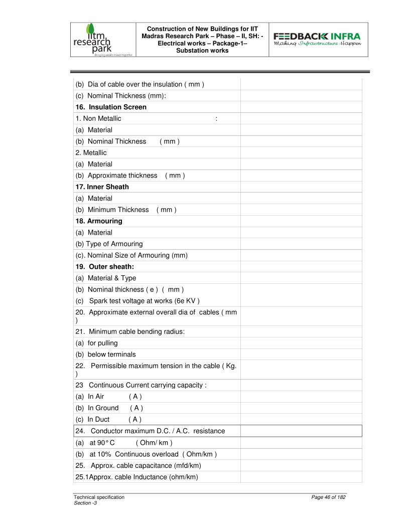
Construction of New Buildings for IIT Madras Research Park – Phase – II, SH: -
Electrical works – Package-1– Substation works
Technical specification Page 46 of 182 Section -3
(b) Dia of cable over the insulation ( mm )
(c) Nominal Thickness (mm):
16. Insulation Screen
1. Non Metallic :
(a) Material
(b) Nominal Thickness ( mm )
2. Metallic
(a) Material
(b) Approximate thickness ( mm )
17. Inner Sheath
(a) Material
(b) Minimum Thickness ( mm )
18. Armouring
(a) Material
(b) Type of Armouring
(c). Nominal Size of Armouring (mm)
19. Outer sheath:
(a) Material & Type
(b) Nominal thickness ( e ) ( mm )
(c) Spark test voltage at works (6e KV )
20. Approximate external overall dia of cables ( mm )
21. Minimum cable bending radius:
(a) for pulling
(b) below terminals
22. Permissible maximum tension in the cable ( Kg. )
23 Continuous Current carrying capacity :
(a) In Air ( A )
(b) In Ground ( A )
(c) In Duct ( A )
24. Conductor maximum D.C. / A.C. resistance
(a) at 90° C ( Ohm/ km )
(b) at 10% Continuous overload ( Ohm/km )
25. Approx. cable capacitance (mfd/km)
25.1Approx. cable Inductance (ohm/km)
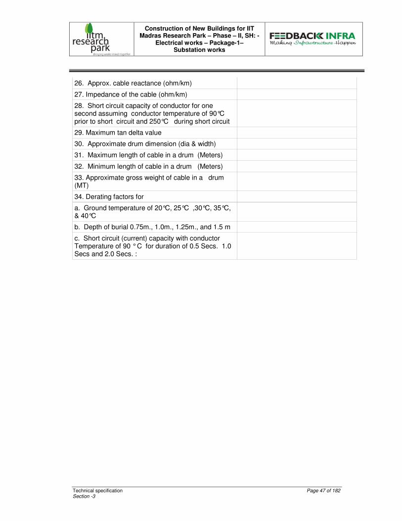
Construction of New Buildings for IIT Madras Research Park – Phase – II, SH: -
Electrical works – Package-1– Substation works
Technical specification Page 47 of 182 Section -3
26. Approx. cable reactance (ohm/km)
27. Impedance of the cable (ohm/km)
28. Short circuit capacity of conductor for one second assuming conductor temperature of 90°C prior to short circuit and 250°C during short circuit
29. Maximum tan delta value
30. Approximate drum dimension (dia & width)
31. Maximum length of cable in a drum (Meters)
32. Minimum length of cable in a drum (Meters)
33. Approximate gross weight of cable in a drum (MT)
34. Derating factors for
a. Ground temperature of 20°C, 25°C ,30°C, 35°C, & 40°C
b. Depth of burial 0.75m., 1.0m., 1.25m., and 1.5 m
c. Short circuit (current) capacity with conductor Temperature of 90 ° C for duration of 0.5 Secs. 1.0 Secs and 2.0 Secs. :
Construction of New Buildings for IIT Madras Research Park – Phase – II, SH: -
Electrical works – Package-1– Substation works
Technical specification Page 48 of 182 Section -3
TECHNICAL SPECIFICATION FOR SANDWICH TYPE BUS DUT
STANDARDS
The equipment covered by this specification shall unless otherwise stated, be designed, constructed and tested in accordance with the latest revisions of relevant standards and shall conform to the regulation of local statutory authorities.
27. IS 2147 : Degree of Protection provided enclosure
28. IS 8623(Part-II) : Particular requirements for Bus trunking system
29. IS 13947 (Part-3) : Specification for Low Voltage Switch gear and control gear.
30. IEC 439-1 & 2/60439-1 & 2 : 1997 & 2000
31. BS 5486/BSEN 60439-1 & 2
GENERAL
The rising mains shall be lightweight, low impedance, non-ventilated, naturally cooled and totally enclosed for protection against mechanical damages and dust accumulation in compact and sandwich type. The degree of protection shall be IP55.
The rising mains shall include as Standard manufactured components, all straight lengths, elbows, termination chambers, expansion (flexible) joints and flanged end box to suit the terminal flange arrangements of the cable end box.
The enclosure shall be electro galvanized steel housing of 1.6 mm thick with epoxy coated by an automated electrostatic process to achieve fire resistance.
Bus Rising mains shall have outgoing tap off boxes into the live bus and designed for feeding to the individual floor areas.
The supply of support materials like clamps, steel channel etc., shall also be included in the scope of this order.
It is the sole responsibility of the suppliers to take the site measurement and verify the same at site in order to manufacture, install and commission the rising mains successfully.
All CEIG/CEA regulations are applicable and any modifications pointed out by CEIG /CEA or any other statutory agencies after commissioning also to be carried out and completed to their satisfaction.
During Installation works any drilling/angle fixing etc on floors/walls should be done only after getting approval from us. (Concrete flooring is done with post tension technology)
Necessary danger labels should be provided at every floor.
BUSBARS AND INSULATION
Construction of New Buildings for IIT Madras Research Park – Phase – II, SH: -
Electrical works – Package-1– Substation works
Technical specification Page 49 of 182 Section -3
11. The entire length of busbar should be made up of 99.9% purity Aluminium conductor having conductivity not less than 65% and short circuit rating shall be not less than 35 kA for 1 sec and joints should be coated with Silver.
12.12.12.12. The entire length of busbars shall be coated with class-F epoxy resin insulation (155 deg C) with uniform thickness of 1.6mm and the flashing point should be 250-300 deg C.
13. All bus bar system shall be equipped with end feeder cabinet.
14. Bus bars shall be identified with red, yellow, blue and black colour tape bands at appropriate places and at terminations
15. Necessary extension chambers to facilitate easy cable termination shall also be provided. EXPANSION JOINTS
1. The bus bar system shall be equipped with standard expansion joints or with expansion bolts in every floor length to compensate thermal elongation of the bus bars.
2. The joints should be of one torque bolt and maintenance free nut system and the bolt should be insulated by a high quality insulation material for heat and impact forces.
3. Joints should have an adjustability for precise alignment to facilitate an easy field installation.
4. Expansion joints shall be installed when necessary and it shall be capable of taking up all the thermal expansions, assuming in full load conditions.
PLUG-IN HOLES
It should be well designed to prevent improper installation of plug-in boxes. There should be four numbers of plug-in holes per floor in each rising main and start from 450mm & maximum 2100 mm from finished floor level.
These points shall be provided with safety shutters to prevent inadvertent touching of bus bars when no tap off box is fitted and to ensure that no foreign matter enters in the bus bar chamber. PLUG-IN BOXES FOR RISING MAINS
Plug-in boxes suitable for specified current rating 4P/TPN MCCB made up of 1.6mm thick electro galvanized sheet steel should be mechanically interlocked with the busduct housing in order to prevent installation or removal of plug-in box while the switch is in ‘ON’ position. Before jaws make contact with the busbar the plug-in box enclosure should make positive ground connection to the busduct housing. Future painting should not damage the grounding.
Plug-in boxes are also to be equipped with internal insulation barriers to prevent accidental contact of housing plate and conductors with live parts which are on the sideline of the protective device during time of cabling. Suitable adaptor boxes to be attached for the termination of cables. Such adaptor boxes shall be of sufficient size to facilitate convenient termination of cables.
Construction of New Buildings for IIT Madras Research Park – Phase – II, SH: -
Electrical works – Package-1– Substation works
Technical specification Page 50 of 182 Section -3
SUPPORTS
Vertical risers of busduct shall be supported adequately with spring hangers at each floor. Immediate supports shall be provided if floor to floor distance exceeds 5 mtrs. TEMPERATURE RISE
The temperature rise at any point in the rising main shall not exceed 55 deg C which is above the ambient temperature of 45 deg C when operating at rated load current. ACCESSORIES
1. All suspension fixings shall be fully tested and approved exclusively as suitable for the installation with particular regard to ambient temperature, environment and loading.
2. The bus system shall be assembled from standard approved components completed at the factory and suitable for an application.
EARTHING
The rising main enclosure shall be earthed by two runs of external earth busbar of 50x6 mm high quality GI ( min 80 microns) shall be fixed both sides on the outer part of the housing throughout the entire length of the Bus duct and to be terminated at regular intervals. (At every floors / every 3 meters). Necessary provision may be made to connect the cable gland-earthing conductor. PAINTING
Enclosures and supports should be painted with epoxy powder coated by an automated
electrostatic process in order to achieve fire resistance. The colour finish is RAL 7032.( with 60 to
70 microns of PP powder)
TESTS
The Rising main bus duct shall be completely assembled, adjusted and tested for operation under simulated conditions to ensure proper functioning of all equipments. All the required tests are to be conducted at our site after installation of bus ducts and rising mains.
a. Types Tests
The Bidder shall furnish two (2) sets of latest type test certificates for all the tests conducted on similar equipments from CPRI or equivalent laboratory along with technical bid.
(αα) Short time current test.
1. Temperature rise test.
2. One-minute power frequency voltage withstand test.
Construction of New Buildings for IIT Madras Research Park – Phase – II, SH: -
Electrical works – Package-1– Substation works
Technical specification Page 51 of 182 Section -3
3. Flame propagation test b. Routine Tests
19. Mechanical operation test.
20. Dielectric test.
14. DRAWINGS AND DOCUMENTS The following drawings and documents shall be furnished in six (6) copies and get approval
before execution of work.
General arrangement drawing for Rising main showing
11. Overall Dimensions for Different rating
12. Terminal locations
13. Total weight/meter
14. Sectional views
15. Three dimensional drawings
16. Fixing details
17. Sectional view of Tap Off Box.
18. Single Line Diagram
19. Technical details for MCCBs.
20. Manufacturing schedule,qualiy assurance plan and test schedule.
21. Calculation for bus bar sizing
22. Catalogues with all technical details
23. Manufacturer & Service Provider Contact Persons, Contact No etc., for all the components.
24. O & M Manual.
INSTALLATION:
The installation of the Rising main shall be carried out by special team of technicians and
engineers trained for such jobs and prior intimation in this regard is to be given to the client with
their proficiency.
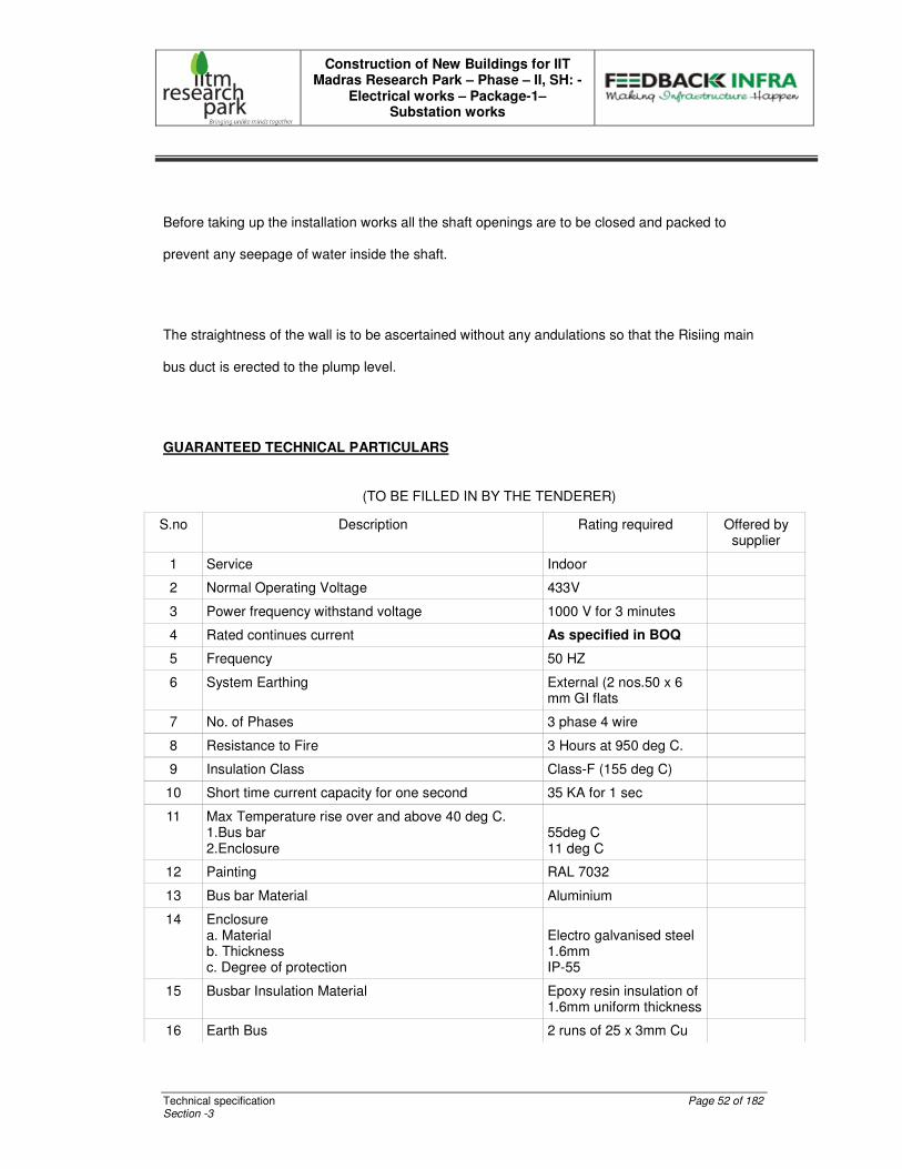
Construction of New Buildings for IIT Madras Research Park – Phase – II, SH: -
Electrical works – Package-1– Substation works
Technical specification Page 52 of 182 Section -3
Before taking up the installation works all the shaft openings are to be closed and packed to
prevent any seepage of water inside the shaft.
The straightness of the wall is to be ascertained without any andulations so that the Risiing main
bus duct is erected to the plump level.
GUARANTEED TECHNICAL PARTICULARS
(TO BE FILLED IN BY THE TENDERER)
S.no Description Rating required Offered by supplier
1 Service Indoor
2 Normal Operating Voltage 433V
3 Power frequency withstand voltage 1000 V for 3 minutes
4 Rated continues current As specified in BOQ
5 Frequency 50 HZ
6 System Earthing External (2 nos.50 x 6 mm GI flats
7 No. of Phases 3 phase 4 wire
8 Resistance to Fire 3 Hours at 950 deg C.
9 Insulation Class Class-F (155 deg C)
10 Short time current capacity for one second 35 KA for 1 sec
11 Max Temperature rise over and above 40 deg C. 1.Bus bar 2.Enclosure
55deg C 11 deg C
12 Painting RAL 7032
13 Bus bar Material Aluminium
14 Enclosure a. Material b. Thickness c. Degree of protection
Electro galvanised steel 1.6mm IP-55
15 Busbar Insulation Material Epoxy resin insulation of 1.6mm uniform thickness
16 Earth Bus 2 runs of 25 x 3mm Cu
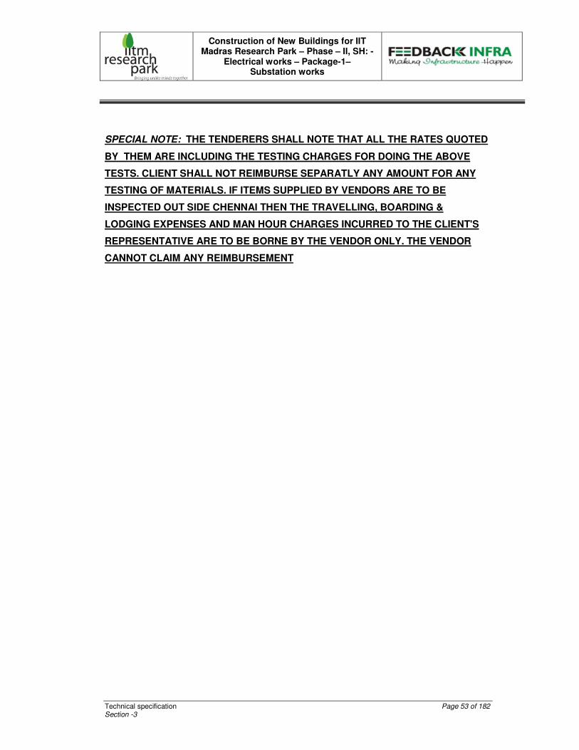
Construction of New Buildings for IIT Madras Research Park – Phase – II, SH: -
Electrical works – Package-1– Substation works
Technical specification Page 53 of 182 Section -3
SPECIAL NOTE: THE TENDERERS SHALL NOTE THAT ALL THE RATES QUOTED
BY THEM ARE INCLUDING THE TESTING CHARGES FOR DOING THE ABOVE
TESTS. CLIENT SHALL NOT REIMBURSE SEPARATLY ANY AMOUNT FOR ANY
TESTING OF MATERIALS. IF ITEMS SUPPLIED BY VENDORS ARE TO BE
INSPECTED OUT SIDE CHENNAI THEN THE TRAVELLING, BOARDING &
LODGING EXPENSES AND MAN HOUR CHARGES INCURRED TO THE CLIENT'S
REPRESENTATIVE ARE TO BE BORNE BY THE VENDOR ONLY. THE VENDOR
CANNOT CLAIM ANY REIMBURSEMENT
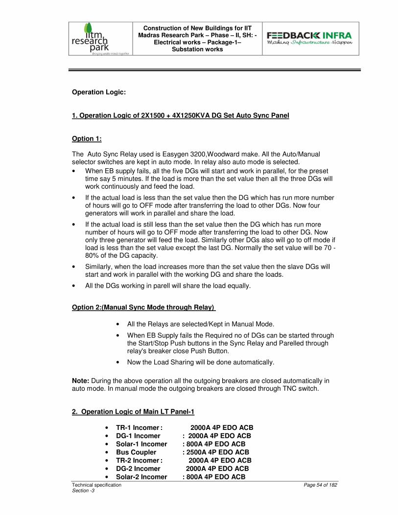
Construction of New Buildings for IIT Madras Research Park – Phase – II, SH: -
Electrical works – Package-1– Substation works
Technical specification Page 54 of 182 Section -3
Operation Logic:
1. Operation Logic of 2X1500 + 4X1250KVA DG Set Auto Sync Panel Option 1: The Auto Sync Relay used is Easygen 3200,Woodward make. All the Auto/Manual selector switches are kept in auto mode. In relay also auto mode is selected.
• When EB supply fails, all the five DGs will start and work in parallel, for the preset time say 5 minutes. If the load is more than the set value then all the three DGs will work continuously and feed the load.
• If the actual load is less than the set value then the DG which has run more number of hours will go to OFF mode after transferring the load to other DGs. Now four generators will work in parallel and share the load.
• If the actual load is still less than the set value then the DG which has run more number of hours will go to OFF mode after transferring the load to other DG. Now only three generator will feed the load. Similarly other DGs also will go to off mode if load is less than the set value except the last DG. Normally the set value will be 70 - 80% of the DG capacity.
• Similarly, when the load increases more than the set value then the slave DGs will start and work in parallel with the working DG and share the loads.
• All the DGs working in parell will share the load equally.
Option 2:(Manual Sync Mode through Relay)
• All the Relays are selected/Kept in Manual Mode.
• When EB Supply fails the Required no of DGs can be started through the Start/Stop Push buttons in the Sync Relay and Parelled through relay's breaker close Push Button.
• Now the Load Sharing will be done automatically.
Note: During the above operation all the outgoing breakers are closed automatically in auto mode. In manual mode the outgoing breakers are closed through TNC switch. 2. Operation Logic of Main LT Panel-1
• TR-1 Incomer : 2000A 4P EDO ACB
• DG-1 Incomer : 2000A 4P EDO ACB
• Solar-1 Incomer : 800A 4P EDO ACB
• Bus Coupler : 2500A 4P EDO ACB
• TR-2 Incomer : 2000A 4P EDO ACB
• DG-2 Incomer 2000A 4P EDO ACB
• Solar-2 Incomer : 800A 4P EDO ACB
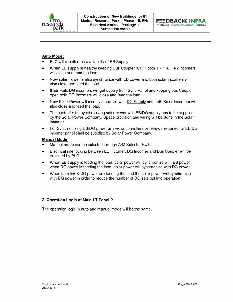
Construction of New Buildings for IIT Madras Research Park – Phase – II, SH: -
Electrical works – Package-1– Substation works
Technical specification Page 55 of 182 Section -3
Auto Mode:
• PLC will monitor the availability of EB Supply.
• When EB supply is healthy keeping Bus Coupler “OFF” both TR-1 & TR-2 incomers will close and feed the load.
• Now solar Power is also synchronize with EB power and both solar incomers will also close and feed the load.
• If EB Fails DG incomers will get supply from Sync Panel and keeping bus Coupler open both DG Incomers will close and feed the load.
• Now Solar Power will also synchronize with DG Supply and both Solar Incomers will also close and feed the load.
• The controller for synchronizing solar power with EB/DG supply has to be supplied by the Solar Power Company. Space provision and wiring will be done in the Solar incomer.
• For Synchronizing EB/DG power any extra controllers or relays if required for EB/DG incomer panel shall be supplied by Solar Power Company.
Manual Mode:
• Manual mode can be selected through A/M Selector Switch.
• Electrical interlocking between EB Incomer, DG Incomer and Bus Coupler will be provided by PLC.
• When EB supply is feeding the load, solar power will synchronize with EB power when DG power is feeding the load, solar power will synchronize with DG power.
• When both EB & DG power are feeding the load the solar power will synchronize with DG power in order to reduce the number of DG sets put into operation.
3. Operation Logic of Main LT Panel-2
The operation logic in auto and manual mode will be the same.
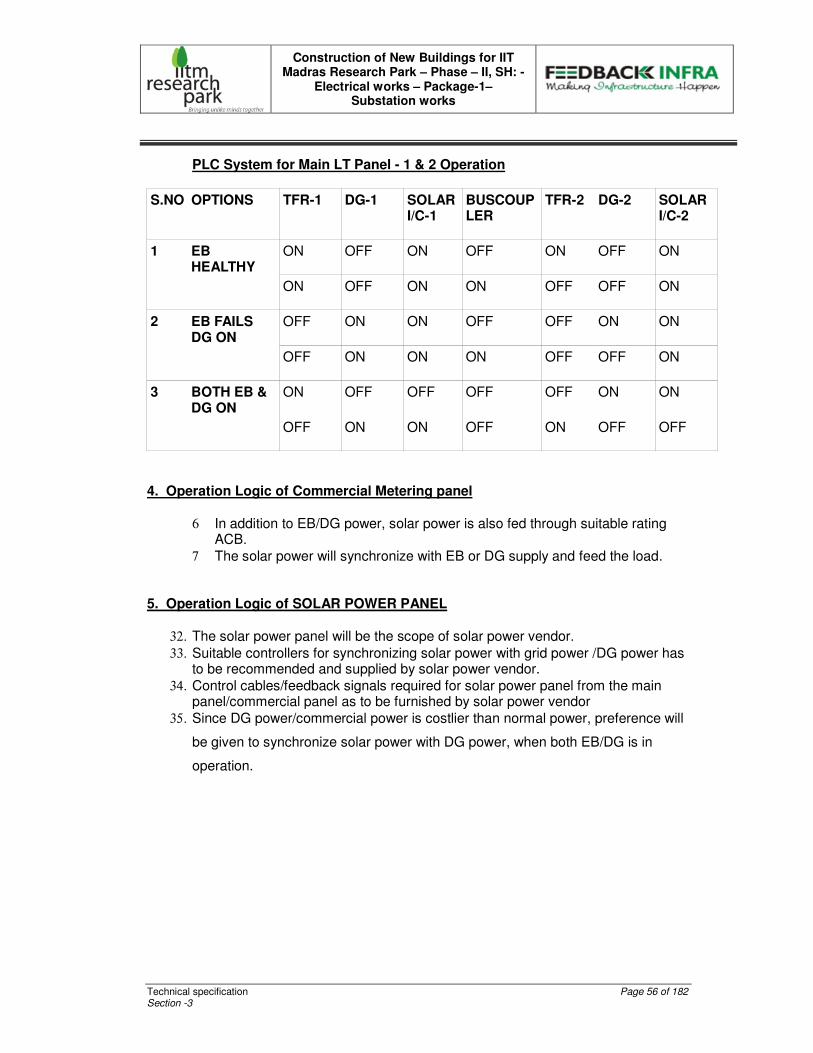
Construction of New Buildings for IIT Madras Research Park – Phase – II, SH: -
Electrical works – Package-1– Substation works
Technical specification Page 56 of 182 Section -3
PLC System for Main LT Panel - 1 & 2 Operation
S.NO OPTIONS TFR-1 DG-1 SOLAR I/C-1
BUSCOUPLER
TFR-2 DG-2 SOLAR I/C-2
ON OFF ON OFF ON OFF ON 1 EB HEALTHY
ON OFF ON ON OFF OFF ON
OFF ON ON OFF OFF ON ON 2 EB FAILS DG ON
OFF ON ON ON OFF OFF ON
ON OFF OFF OFF OFF ON ON 3 BOTH EB & DG ON
OFF ON ON OFF ON OFF OFF
4. Operation Logic of Commercial Metering panel
6 In addition to EB/DG power, solar power is also fed through suitable rating ACB.
7 The solar power will synchronize with EB or DG supply and feed the load. 5. Operation Logic of SOLAR POWER PANEL
32. The solar power panel will be the scope of solar power vendor.
33. Suitable controllers for synchronizing solar power with grid power /DG power has to be recommended and supplied by solar power vendor.
34. Control cables/feedback signals required for solar power panel from the main panel/commercial panel as to be furnished by solar power vendor
35. Since DG power/commercial power is costlier than normal power, preference will
be given to synchronize solar power with DG power, when both EB/DG is in
operation.
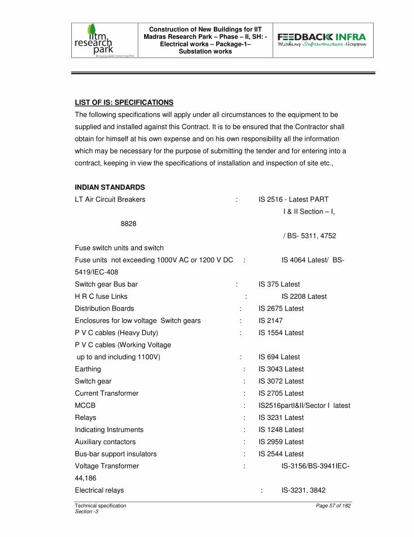
Construction of New Buildings for IIT Madras Research Park – Phase – II, SH: -
Electrical works – Package-1– Substation works
Technical specification Page 57 of 182 Section -3
LIST OF IS: SPECIFICATIONS
The following specifications will apply under all circumstances to the equipment to be
supplied and installed against this Contract. It is to be ensured that the Contractor shall
obtain for himself at his own expense and on his own responsibility all the information
which may be necessary for the purpose of submitting the tender and for entering into a
contract, keeping in view the specifications of installation and inspection of site etc.,
INDIAN STANDARDS
LT Air Circuit Breakers : IS 2516 - Latest PART
I & II Section – I,
8828
/ BS- 5311, 4752
Fuse switch units and switch
Fuse units not exceeding 1000V AC or 1200 V DC : IS 4064 Latest/ BS-
5419/IEC-408
Switch gear Bus bar : IS 375 Latest
H R C fuse Links : IS 2208 Latest
Distribution Boards : IS 2675 Latest
Enclosures for low voltage Switch gears : IS 2147
P V C cables (Heavy Duty) : IS 1554 Latest
P V C cables (Working Voltage
up to and including 1100V) : IS 694 Latest
Earthing : IS 3043 Latest
Switch gear : IS 3072 Latest
Current Transformer : IS 2705 Latest
MCCB : IS2516partI&II/Sector I latest
Relays : IS 3231 Latest
Indicating Instruments : IS 1248 Latest
Auxiliary contactors : IS 2959 Latest
Bus-bar support insulators : IS 2544 Latest
Voltage Transformer : IS-3156/BS-3941IEC-
44,186
Electrical relays : IS-3231, 3842

Construction of New Buildings for IIT Madras Research Park – Phase – II, SH: -
Electrical works – Package-1– Substation works
Technical specification Page 58 of 182 Section -3
Degree of protection provided by enclosures for low voltage : IS-
2147/IEC-144
Switchgears and control gear
Dimensions for panel mounted indicating and : IS-2419
recording electrical instrument
Marking and arrangement for switchgear, busbars, main : IS-375
connection and auxiliary wiring.
Code of practice for selection, Installations and maintenance of : IS-10118 Fuses.
Code of practice for safety procedure in Electrical work : IS 5216 (Part-1):
1982
Construction of New Buildings for IIT Madras Research Park – Phase – II, SH: -
Electrical works – Package-1– Substation works
Technical specification Page 59 of 182 Section -3
TECHNICAL SPECIFICATION FOR LT PCC PANEL BOARDS
SCOPE OF SUPPLY
This specification covers the design, manufacture,factory testing and Supply,
Integration, delivery and Supervision during installation, earthing , field testing &
commissioning of LT Panel Boards (Form 4) incorporating ACB, MCCB, Metering and
Protection etc.,
The 415V Switchboard shall be capable of continuous and reliable operation at the full
load rating specified where continuity of operation is of prime importance.
The LV Breaker shall be capable of withstanding the severest stresses likely to occur in
actual service and of resisting rough handling during transport.
Note: Integration includes supply of materials like Meters, CTs, Bus bars, Insulators,
Indicating Lamps, Metering Fuses, PLC interface etc.,
STANDARDS
The Tenderer shall control the quality of items and services to meet the requirements of
this specification, applicable codes and standards and other procurement documents.
The LV Panel Boards shall comply with the latest issue of the following standards.
IS 8623 – General requirement for factory built assemblies upto 1000 Volts.
IS 13947-2 – A.C. Circuit breaker requirements – Voltage not exceeding 1000Vs
Part I & II, Sec 1 and IEC 60947 part I & III
IS 2705 – Specification for current transformers
IS 1248 – Specification for direct acting electrical indicating instruments.
IS 3156 – Voltage transformers
IS 3231 – Relays
IS 13703 – Specification for HRC cartridge fuse links upto 650 Volts.

Construction of New Buildings for IIT Madras Research Park – Phase – II, SH: -
Electrical works – Package-1– Substation works
Technical specification Page 60 of 182 Section -3
IS 11353 – Marking and identification of conductors and apparatus
IS 13947 – Part I & II – Moulded Case Circuit Breaker
IS 6005 – Code of practice for phosphating Iron and Steel
IS 5082 – Wrought Aluminium & Aluminium Alloy for Electrical Purposes
CONSTRUCTION
The LT Panels shall be of, Metal enclosed, indoor, floor mounted self standing type,
compartmentalized modular and easily extendable type, top/bottom entry as specified in
the BOQ.
Made up of the requisite vertical sections, which when coupled together shall form
continuous dead front switchboards.
The LV Panels shall be of dust and vermin proof of MS sheet steel enclosure with
degree of protection IP 54.
The panel shall be readily extensible on both sides by the addition of vertical sections
after removal of the end covers. The main buabars shall have slotted holes on both the
sides for easy extension.
The panels shall be constructed only of materials capable of withstanding the
mechanical, electrical and thermal stresses as well as the effects of humidity, which are
likely to be encountered in sea shore areas like chennai.
Each vertical section shall comprise: -
A front-framed structure of rolled/folded sheet steel channel section, of minimum 14SWG
thickness, rigidly bolted together. This structure shall house the components contributing
to the major weight of the equipment, such as Air circuit breaker cassettes, MCCB’s ,
main horizontal bus bars, vertical risers and other front mounted accessories.
The structure shall be mounted on a rigid base frame of folded sheet steel of minimum
3mm thickness and 100mm height or equivalent MS channels. The design shall ensure

Construction of New Buildings for IIT Madras Research Park – Phase – II, SH: -
Electrical works – Package-1– Substation works
Technical specification Page 61 of 182 Section -3
that weight of the components is adequately supported without deformation or loss of
alignment during transit.
The design shall ensure generous availability of space for termination and maintenance
of cabling, and adequate safety for working in one vertical section without coming into
accidental contact with live parts in an adjacent section.
A cover plate at the top of vertical section, provided with ventilating hood where
necessary aperture for ventilation shall be covered with a perforated sheet to prevent
entry of vermin.
Front doors and rear covers fitted with dust excluding synthetic rubber gaskets with
fasteners designed to ensure proper compressions of gaskets. When covers are
provided in place of doors, generous overlap shall be assured between sheet steel
surface with closely spaced fasteners to preclude the entry of dust.
The height of the panel shall not be more than 2100mm. The total depth of the panel
should be adequate to cater for proper cabling space and shall not exceed 1200mm for
ACB sections.
Doors shall be minimum 14SWG sheet steel. Sheet steel shrouds and partitions shall be
of minimum 16SWG thickness. All sheet steelwork forming the exterior of switchboards
shall be smoothly finished, leveled and free from flaws. The corners should be rounded.
All insulating material used in the construction of the equipment shall be of non-
hygroscopic material, duly treated to withstand the effects of high humidity(Chennai
climate), high temperature tropical ambient service conditions.
Metallic / Insulated barriers / Hylum Shrouding shall be provided within vertical sections
and between adjacent sections to ensure prevention of accidental contact.
All doors/covers providing access to live power equipments circuits shall be provided tool
operated fasteners to prevent unauthorized access.
Provision shall be made for permanently earthing the frames, doors and other metal part
of the switchgear by two independent connections.
Construction of New Buildings for IIT Madras Research Park – Phase – II, SH: -
Electrical works – Package-1– Substation works
Technical specification Page 62 of 182 Section -3
Operating devices shall be incorporated only in the front of the switchgear. No handle
shall be located more than 450mm and not higher than 1800mm above finished floor
level.
Suitable eyebolt for lifting of panel shall be provided.
BUSBARS
The bus bars shall be air insulated and made of high conductivity, high strength, 99.99%
Pure Electrolytic grade Aluminium.
A current density of 0.8 A / Sq. mm. shall be considered for Aluminium bus bars. For
Main distribution Boards the size of bus bars shall be designed on the basis of a short
circuit rating of 70kA for 1 sec and for other sub distribution boards the bus bars shall be
designed for 50kA and 35kA as indicated in SLD. Interleaving type bus bar system is
preferable for LT Panels of high amperage capacity.
The bus bars shall be suitably braced with non-hygroscopic SMC supports, the neutral
as well as the earth bar should also be capable of withstanding the stress of electrical
fault. Ridges shall be provided on the SMC supports to prevent tracking between
adjacent bus bars.
As per standards large clearances and Creepage distances shall be provided on the bus
bars system to minimize the possibility of a fault.
High tensile bolts and star washers shall be used to minimize the possibility of a fault.(
Spring washers of split type not permitted)
Connections from the main bus bars to functional circuits shall be arranged and
supported so as to withstand without any damage or deformation the thermal and
dynamic stresses due to short circuit currents.
Apparatus forming part of the panel shall have the following recommended minimum
clearances for an insulated bus bars or should as per relevant IS code 4237 – 1967.

Construction of New Buildings for IIT Madras Research Park – Phase – II, SH: -
Electrical works – Package-1– Substation works
Technical specification Page 63 of 182 Section -3
Between phases – 25mm
Between phases and neutral – 25mm
Between phases and earth – 19mm
Between neutral and earth – 19mm
For lengthy bus bars suitable expansion joints shall be provided. (The length beyond
4.5m shall be provided with necessary flexible connectors for bus expansion and
contraction. The flexible material shall be same as that of bus bar to avoid bimetallic
reaction).
The main bus bar shall have uniform current ratings through their length. The current
rating of the neutral shall be equal of the size that of the phase bus bars throughout the
length of the switchboard.
The size of the branch busbar shall be suitable to withstand the panel fault level
irrespective of the current in the vertical section and also the current rating of that
particular branch.
For the vertical section the capacity of the busbar should not only rated for the current
carrying section but also cross section of the busbar provided to withstand the for the
main busbar is designed
The bus bar and supports shall be capable of withstanding 70kA Short circuit current at
415 V for 1 Sec in the LT panels and 50/35kA for Sub Panels.
Only zinc passivated or cadmium plated high tensile strength steel bolts, nuts and
washers shall be used for all bus bar joints and supports. All bus bar supports shall be
SMC only.
All bus bars shall be colour coded by means of identifying colour rings at every power tap
off point. Red, yellow and blue colour shall be used for Phase bus bars and Black
colour shall be used for neutral bus bars. Each bus bar shall be insulated with heat
shrinkable colored PVC sleeves.

Construction of New Buildings for IIT Madras Research Park – Phase – II, SH: -
Electrical works – Package-1– Substation works
Technical specification Page 64 of 182 Section -3
The Bus bars shall be capable of withstanding rated capacity without any deration at
70°C.
The rating of bus bars shall be same as that of incomer breaker rating.
Bus bars shall be housed in a separate chamber, which shall be accessible for inspection
when it is required. The Bus bar chambers shall have bolted cover only and hinged doors
are not permitted. Wherever hinged doors are used suitable insulation barriers are to be
provided to avoid accidental contacts of live parts.
POWER CONNECTIONS
Interconnection of various switchgear components with the main bus bars, shall be done
with inter connection bus bars which shall be directly mounted on the bus bar. Adaptors
to be tightened to the recommended torque for a firm & reliable connection, using
specified tools. Switchgear components to be mounted separately on the mounting
plate. The cable entry shall be top / bottom as per BOQ.
All components (Bus bars, inter connection , supports, switchgear components etc.) shall
be mounted based on open system.
Terminal extension bus bars to be adequately provided to take outputs from the
switchgear components, with suitable size of cable.
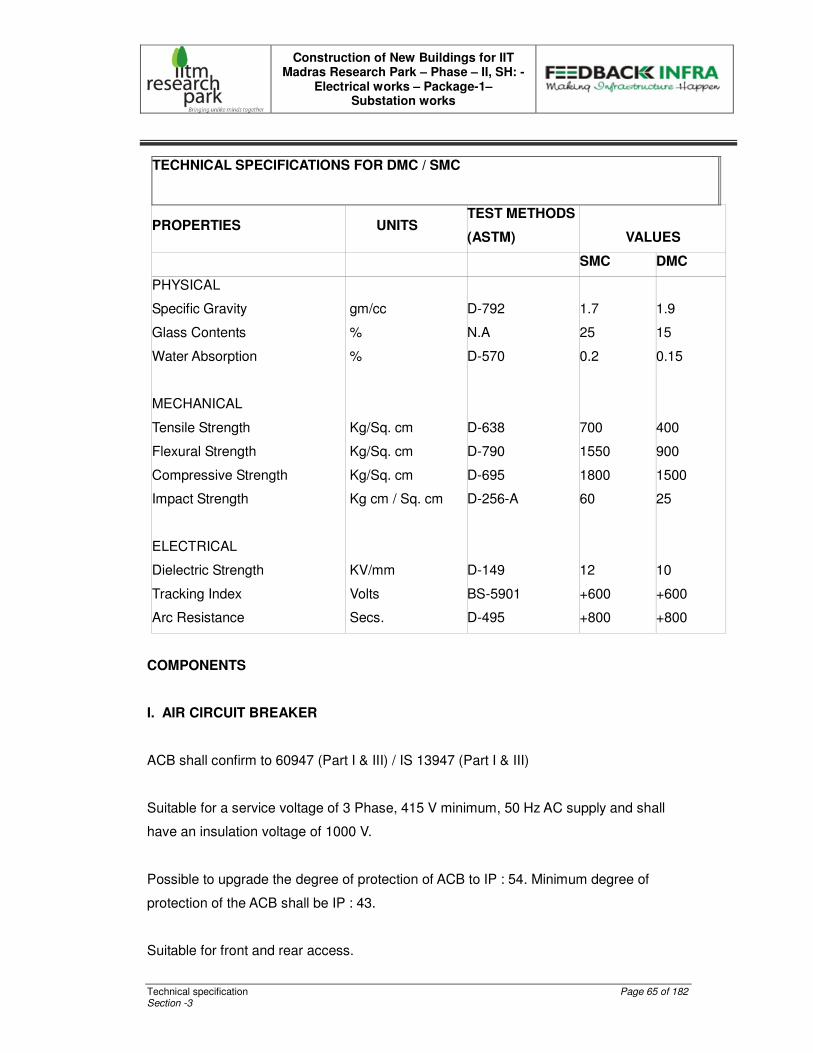
Construction of New Buildings for IIT Madras Research Park – Phase – II, SH: -
Electrical works – Package-1– Substation works
Technical specification Page 65 of 182 Section -3
TECHNICAL SPECIFICATIONS FOR DMC / SMC
PROPERTIES UNITS TEST METHODS
(ASTM) VALUES
SMC DMC
PHYSICAL
Specific Gravity gm/cc D-792 1.7 1.9
Glass Contents % N.A 25 15
Water Absorption % D-570 0.2 0.15
MECHANICAL
Tensile Strength Kg/Sq. cm D-638 700 400
Flexural Strength Kg/Sq. cm D-790 1550 900
Compressive Strength Kg/Sq. cm D-695 1800 1500
Impact Strength Kg cm / Sq. cm D-256-A 60 25
ELECTRICAL
Dielectric Strength KV/mm D-149 12 10
Tracking Index Volts BS-5901 +600 +600
Arc Resistance Secs. D-495 +800 +800
COMPONENTS
I. AIR CIRCUIT BREAKER
ACB shall confirm to 60947 (Part I & III) / IS 13947 (Part I & III)
Suitable for a service voltage of 3 Phase, 415 V minimum, 50 Hz AC supply and shall
have an insulation voltage of 1000 V.
Possible to upgrade the degree of protection of ACB to IP : 54. Minimum degree of
protection of the ACB shall be IP : 43.
Suitable for front and rear access.
Construction of New Buildings for IIT Madras Research Park – Phase – II, SH: -
Electrical works – Package-1– Substation works
Technical specification Page 66 of 182 Section -3
The ACB shall have the following inbuilt protections with microprocessor based / thermal
magnetic releases.
Overload
short circuit
Earth fault
Instantaneous
Under and over voltage protections
The ACB shall be provided with 4 NO & 4 NC auxiliary contacts.
INTERLOCK AND SAFETY ARRANGEMENT
The ACB's shall be Four pole draw out type. ( Electrical or Manual type specified in
SLD)
Any attempt to with draw the Air Circuit Breaker, when the unit is in service, will
automatically trip the breaker. It shall be possible to rack the ACB to disconnected
position with the door closed.
Remote electrical indication of the circuit breaker status should be possible for all the
positions.
Possible to close the ACB electrically and the spring charging time shall be preferably by
less than 5 seconds. The mechanism shall be of stored energy type. The electrical
closing mechanism shall have a built- in anti pumping feature minimum 6 NO & 6 NC
control contacts should be available for external use.
RATING AND BREAKING CAPACITY
The ACB shall have Minimum Service Breaking Capacity (Ics) equal to Ultimate Breaking
Capacity (Icu).
The Minimum Service Breaking Capacity (Ics) for 2500/2000/1600/800/630 AMPS is
50KA. or as specified in SLD
Construction of New Buildings for IIT Madras Research Park – Phase – II, SH: -
Electrical works – Package-1– Substation works
Technical specification Page 67 of 182 Section -3
PROTECTION
There shall be an option to select the curves (minimum 80 combinations) and also
change the operating time for minimum of 8 settings for overload, 7 for short circuit and 7
settings for earth fault.
There shall be facility for selecting various type of E/F protection if required.
Trip history feature shall be available.
Neutral protection of 50 to 100% shall be available.
Self - diagnostic malfunction alarm for microprocessor should be available.
"The trip unit shall have thermal memory.
I2 t cropping facility shall be available for short circuit and earth fault.
Facility should be there to monitor the load and intimate a pre-trip alarm or have load-
shedding feature.
Fault indication by means of LED should be available for Overload, Short Circuit and
Earth Fault and also LCD display for indication of menu's, settings, recorded information.
Trip reset facility should be manual / automatic.
It shall be possible to trip (or) close the Breaker through RS 485 communication
interface.
MOULDED CASE CIRCUIT BREAKER
MCCBs should comply with IEC 947 Part 2. / IS 13947
The MCCB shall be suitable for universal mounting (i.e) the Load / Line must be
interchangeable.

Construction of New Buildings for IIT Madras Research Park – Phase – II, SH: -
Electrical works – Package-1– Substation works
Technical specification Page 68 of 182 Section -3
The MCCB shall be suitable for operating Voltage of 415 V minimum and an Insulation
Voltage of 1000 V.
Rating and Breaking Capacity
The Service Breaking Capacity (Ics) in KA for MCCB shall be as specified in SLD: -
PROTECTION
Overload and short circuit setting details:-
All outgoing MCCBs in the Main distribution boards and incoming MCCBs of all Sub
distribution panel boards shall be of adjustable overload and short circuit protection
settings.
The outgoing MCCBs in the Sub Panels needs adjustable thermal overload settings only
and fixed short circuit setting.
The Thermal setting shall be adjustable from 40% to 100% of its normal current.
The magnetic setting shall be continuously adjustable from 6 to 10 times of its set
current.
Trip reset should be available Manual / Automatic.
Note: If specifically mentioned in SLD or BOQ microprocessor based MCCBs shall be
provided
CONTACTORS
Contactors shall comply with IS 13947 for general rules and IS13947-4-1 for standards
pertaining to contactors and motor starters. The contactor shall be capable of
withstanding breaking & making capacities as follows:
AC3 Category
Making Current - 10 times Rated Current
Breaking current - 8 times Rated current

Construction of New Buildings for IIT Madras Research Park – Phase – II, SH: -
Electrical works – Package-1– Substation works
Technical specification Page 69 of 182 Section -3
Contactor shall be capable of withstanding an impulse voltage of 8 KV and have an
insulation voltage of 1000V.
The Contactors shall be capable of frequent switching and should operate without any
deration at 55 ° C for AC3 application.
The coil shall be of suitable voltage of control circuit proposed and the insulation class
shall be preferably H class, to sustain frequent switching operations. The auxiliary
contact block shall have a switching capacity of 240V at 2A. Contactors shall have one
auxiliary in-built and it shall be possible to have additional NO & NC contacts in steps of
two. The contactors for the capacitors shall be of capacitor duty.
WIRING
Control, signaling, protection and instrument circuits shall be done with PVC Insulated
FRLS multi strand copper conductors. The insulation grade for these wires shall be 1100
volts. All control wiring shall preferably be enclosed in plastic channels or neatly bunched
together.
For control circuits, 1.5 Sq. mm size wires shall be used. Each wire shall be terminated
at a separate terminal. Termination of two outgoing wires on a single terminal will not be
acceptable. Wires shall not be joined or tied between terminal parts. Shorting links shall
be provided for all C.T. Terminals. For CT circuits 2.5 sq mm wires shall be used.
Each wire shall be identified at both ends by self-sticking wire marker tapes or PVC
Ferrules. Ferruling of wires shall be as per relevant IS.
A minimum of 20% spare terminals shall be provided on each terminal block. Conductors
shall be terminated with adequately sized compression type lugs. "ELMEX" (direct
conductor termination) type terminals will be acceptable for wires upto 10 sq. mm.
The control terminals shall be mounted in such a way that they are separate from the
power terminals and shall be easily accessible without any hindrance from the power
circuitry.
Construction of New Buildings for IIT Madras Research Park – Phase – II, SH: -
Electrical works – Package-1– Substation works
Technical specification Page 70 of 182 Section -3
The wiring shall be complete in all respects so as to ensure proper function of control,
protection and interlocking schemes.
CURRENT TRANSFORMERS
Current Transformers cast resin insulated type for feeders rated above 200 A. The CT
ratio and VA burden shall be such that it can power all meters.
Current transformers shall generally conform to IS: 2705.
Current transformers for instruments shall have an accuracy class 1.0 for MV Panels
and accuracy limit factor less than 5.0.
The current transformers shall be capable of withstanding the peak momentary short
circuit current for 1.0 second.
The neutral side of the current transformers shall normally be earthed through a link.
MEASURING INSTRUMENTS
All measuring instruments shall be of flush mounting, digital type and the size of
indicating instruments shall be 96 x 96 Sq. mm.
A.C. 3 Phase digital type Smart Demand Controller shall be provided for all the incoming
breakers.
The display shall be multiform LCD display with back lit.
The accuracy class shall be 0.5S.
The meter should confirm to IEC 61557-12.
Construction of New Buildings for IIT Madras Research Park – Phase – II, SH: -
Electrical works – Package-1– Substation works
Technical specification Page 71 of 182 Section -3
INDICATING LAMPS
Indicating lamps shall be of LED type, low watt consumption, provided with series
resistor where necessary and with translucent lamp covers. Bulbs and lenses shall be
easily replaceable from the front.
Following Indicating Lamps are required on the panel having lens colours as detailed
below :
RYB Indication Lamps : RED, YELLOW, BLUE
Breaker ON : RED
Breaker OFF : GREEN
Auto Trip : AMBER
RELAYS
All protective relays shall be of numerical type, suitable for flush mounting and fitted with
dust tight covers. All relays shall be mounted on the front of the panel and shall be
specified as per requirement. The current and the voltage coils shall be provided as
specified.
All relays shall have built-in flag to indicate operation. It shall be possible to reset the
flag without opening the relay case. All tripping relays shall be suitable to operate on the
specified voltage.
Transformer protection relays such as Two Over current & one Earth fault relay similar to
CDG - 31 with instantaneous trip shall be provided with following Plug setting O/L 50-
200% and E/F 20-80% relay.
It shall be possible to trip (or) close the Breaker through RS 485 communication
interface.

Construction of New Buildings for IIT Madras Research Park – Phase – II, SH: -
Electrical works – Package-1– Substation works
Technical specification Page 72 of 182 Section -3
LIGHTNING & SURGE ARRESTORS
LIGHTNING & SWITCHING SURGE PROTECTION FOR LT PANELS
The power supply of all the sub distribution panels shall be protected by suitable lightning
arrestor to take of 7KA / Pole of 10 / 350 Micro second of lightning surges for each phase
to neutral and 25KA / Pole of 10 / 350 Micro second of lightning surges for neutral to
earth.
In addition the surge arrestor should also be capable of handling a nominal discharge
current of 30KA / Pole of 8 / 20 Micro second of switching surges a maximum discharge
current of 50 KA / Pole of 8 / 20 Micro second of switching surges.
It should be a plug in type arrestor with a dynamic separating device.
SWITCHING SURGE PROTECTION FOR DISTRIBUTION BOARDS / BRANCH
PANELS
The power supply of all the distribution boards / sub panels shall be protected by suitable
SPD (Surge protection device) to handle maximum discharge current of 40KA / Pole of 8
/ 20 Micro second of switching surges for Line to Neutral and maximum discharge
current of 50 KA / Pole of 8 / 20 Micro Second of switching surges. It should be a plug in
type arrestor with a dynamic separating device.
CABLE TERMINATIONS
The cabling chamber of adequate size for accommodation, support and termination of
Copper / Aluminium cables shall be provided at the rear.
Ample space for connection of the cables shall be provided front / rear of the switch
board. The cable termination arrangement shall be of adequate size and design to
receive the required number of cables as required. Proper clamping cable clamping
arrangements shall be provided.
Construction of New Buildings for IIT Madras Research Park – Phase – II, SH: -
Electrical works – Package-1– Substation works
Technical specification Page 73 of 182 Section -3
Detachable gland plate of 5 mm thickness shall be provided for the cable entry into the
panel. Sufficient space shall be provided to avoid sharp bending and facilitate easy
connection. Suitable shrouds shall be provided to prevent accident contact with live
outgoing terminations of other feeders while carrying out maintenance on one feeder.
LABLES
Every switchboard, switchboard control contactor, time switch, relay, indicator lamp,
meter, motor starter, link and any control or protection equipment within or on a
switchboard shall be clearly and accurately labeled.
Labels shall be engraved laminated plastic or photo anodized rigid aluminum and shall
comply with the following requirements.
Except where otherwise required labels shall be fixed adjacent to, but not on any item of
equipment.
Engraved lettering shall be white on a black background, except that the label for a main
switch shall have red lettering on a white background, and warning and caution labels
shall have white lettering on a red background.
Labels shall be securely fixed by Screws and adhesive, are fixed in an extruded
aluminum section which shall be countersunk screw fixed or countersunk riveted to the
panel. Screws shall be tightened with nuts or into tapped holes in the switchboard.
Mechanically expanded plastic rivets of minimum 6 mm. head diameter are acceptable
instead of screws. Aluminum rivets may be used to fix aluminum labels only. Self –
tapping screws, thread – cutting screws or other fixing are not acceptable.
LABELS ON EXTERIOR OF SWITCHBOARDS
All switchboards shall be labeled with the manufacture’s name. A switchboard
designation label shall be provided. Engraved letter shall be Black background with
white lettering. For other than main switchboards, the designation label shall also state
the source of electrical supply.
Construction of New Buildings for IIT Madras Research Park – Phase – II, SH: -
Electrical works – Package-1– Substation works
Technical specification Page 74 of 182 Section -3
Separate sections of enclosures shall be identified. The label for any section or
enclosure containing supply Authority equipment shall be to the satisfaction of the Client /
Consultant. Every switchboard control shall be labeled and shall include:
Circuit designation for all main switches, main controls and sub main controls. Details of
the Consumer’s mains and all sub mains. Incoming bus bar or cable rating. The
minimum height of lettering shall be 6mm.
EARTHING
Switchgears in the panel shall be provided with double earth connection of size indicated
in the schedule and connected to the earth bus.
Earth bus bar shall be supported at regular intervals.
All instruments and metering panel doors shall be connected to earth by using 2.5 sq.
mm. 650V, FRLS PVC multi stranded copper conductor or flexible braided copper wire
of equivalent size and directly connected to the earth bus of the panels
The materials and size of the earth bus bar shall be as specified in the BOQ. At either
end of the earth bus provision shall be made for bolting the earth bus to the earth
electrode with nuts & bolts and spring washer. The earth bus bar shall run along the
entire length of the board.
PAINTING
All metal surfaces shall be chemically cleaned, degreased and pickled in acid to produce
a smooth clean surface, free of scale, grease and rust.
After cleaning, phosphating and passivation treatment, the panel shall be given matt
finish powder coating with PP powder to thickness of 60 to 70 microns RAL 7032 in light
gray. Sufficient quantity of touch up paint of the same colour shall be furnished for
application at site.

Construction of New Buildings for IIT Madras Research Park – Phase – II, SH: -
Electrical works – Package-1– Substation works
Technical specification Page 75 of 182 Section -3
SYNCHRONISING PANELS
It is proposed to synchronise 4 nos of 1250 kVA & 2nos 1500KVA DG sets in a single
panel with outputs and bus couplers as shown in the SLD. The busbars and ACBs shal
be suitable to withstand the specified fault level during all the four DG sets run in parallel.
The incoming and out going of the synchronising panel shall be suitable for connecting
conventional bus ducts of specified ratings.
The bus bar arrangement of Dg sync panel will be interleived type.
SYNCHRONISING & LOAD SHARING RELAYS
The synchronising and load sharing relay shall be microprocessor based relay capable of
controlling both governor and AVR. All the synchronising relays shall be connected to
each other by a Controller Area Network. The relays shall be able to program to operate
required no of DG sets depending upon the load. The relays shall have the following
features.
Auto synchronising
Load sharing
Reverse power protection
Over current and short circuit protection (IDMT)
Earth fault protection
Neutral logic control
KWH monitoring
KWH & KVAR control
Load dependent start stop
Running hours records
Selection of priority of DG sets
Load reserve features.
IMPORTANT NOTE:
The control cable connection between sync panel and the DG set has to be done
by the panel supplier. It is the responsibility of the vendor to co ordinate with DG
supplier for the interconnection and testing the synchronising scheme.
Construction of New Buildings for IIT Madras Research Park – Phase – II, SH: -
Electrical works – Package-1– Substation works
Technical specification Page 76 of 182 Section -3
GENERAL
Inter panel partitions / barriers in sheet steel are required to be provided.
Bus bar joint shrouds are required to be provided and shall be of clip – on type reusable
so that it can be easily removed and refitted.
All internal wiring shall be done with crimping type lugs and all terminals are to be
identified / ferulled properly.
All vacant compartments above 100mm to be provided with earth strip. “Danger” labels
on rear doors shall be provided.
Necessary terminals are to be provided for BMS interface at all Panels. Data sheet shall
be referred for specification of the ACB & MCCB to be used in panels.
No alterations drill holes welding etc., are to be done at site after the panel boards are
received from the factory.
The panel boards shall complete with all rules & regulations as per CEIG/CEA
norms and any modifications pointed out by them or any other statuary agencies
after commissioning also to be carried out and completed at free of cost.
INSPECTION
Fully assembled Panel boards shall be offered for inspection at works. Materials shall be
dispatched to site only after issuing the dispatch clearance by the representative of client
/consultants.
Stage 1 Inspection : During Assembly of Panel
Stage 2 Inspection : Before Dispatch
The readiness should be informed at least fifteen days before the proposed date of
Inspection.
Construction of New Buildings for IIT Madras Research Park – Phase – II, SH: -
Electrical works – Package-1– Substation works
Technical specification Page 77 of 182 Section -3
TESTS
The Panel design shall have undergone all the type tests as per IS: 8623. Type test
certificate shall be submitted along with the panels.
VISUAL TESTS
25. Corrosion test
26. Paint inspection
27. Physical verification check
28. Rubber gasket test.
29. Megger Test.
ROUTINE TESTS
Routine test as per IS: 8623 on each completed switch boards shall be carried out in the
factory and witnessed by client / consultants before dispatch and test certificates for the
same shall be submitted.
Milli volt drop test on Rigid and expansion joints.
COMMISSIONING
Pre-commissioning Checks and Tests shall be conducted at site by you at free of cost
and certificate shall be furnished.
The supplier shall render the service of his supervisor during the Installation and
commissioning of the panels by other agency at free of cost.
The quoted price shall be inclusive of all necessary commissioning spares.
Construction of New Buildings for IIT Madras Research Park – Phase – II, SH: -
Electrical works – Package-1– Substation works
Technical specification Page 78 of 182 Section -3
DRAWINGS AND MANUALS
Vendors shall furnish the following drawings for Client / Consultant approval before
fabrication of the panel.
Tenderer shall also provide detailed GA diagram, sectional drawings, control wiring
diagram, Terminal drawings and other drawings with all dimensions indicating
compartments cutouts, drill holes etc ., for all the panel boards to the Client /
Consultant
Front and rear view of all switch boards indicating Switch Gear arrangements of
Various feeders/starters giving its location numbers and tag numbers for each as per
single line diagram.
Typical control schematic diagram for each type giving type designation to be referred
on Single line diagram.
Switch board foundation/fixing details with all dimensions and details of shipping
sections. All the catalogues, manuals pertaining to each and every ACB, MCCB, Meters,
Relays, CTs etc should be sent along with the panel boards.
Bill of Materials used in panels indicating the make of each items
Manufacturers and service providers address, contact person, contact no etc., has to be
sent to us for all the components.
Construction of New Buildings for IIT Madras Research Park – Phase – II, SH: -
Electrical works – Package-1– Substation works
Technical specification Page 79 of 182 Section -3
SPARES AND TOOLS
The commissioning and maintenance spares required for installing the LV Switch board
shall be quoted separately.
The tools required for the LV Switch boards also listed and quoted separately.
SPECIAL NOTE: THE TENDERERS SHALL NOTE THAT ALL THE RATES QUOTED
BY THEM ARE INCLUDING THE TESTING CHARGES FOR DOING THE ABOVE
TESTS. CLIENT SHALL NOT REIMBURSE SEPARATLY ANY AMOUNT FOR ANY
TESTING OF MATERIALS. IF ITEMS SUPPLIED BY VENDORS ARE TO BE
INSPECTED OUT SIDE CHENNAI THEN THE TRAVELLING, BOARDING &
LODGING EXPENSES AND MAN HOUR CHARGES INCURRED TO THE CLIENT'S
REPRESENTATIVE ARE TO BE BORNE BY THE VENDOR ONLY. THE VENDOR
CANNOT CLAIM ANY REIMBURSEMENT
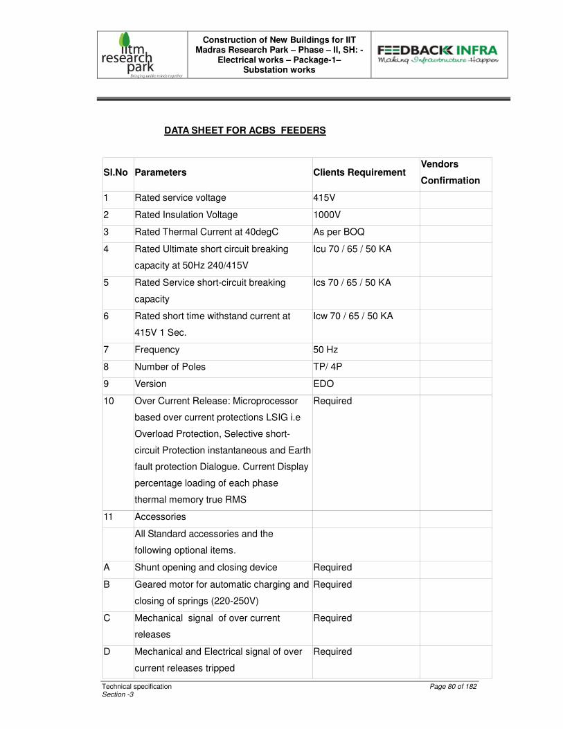
Construction of New Buildings for IIT Madras Research Park – Phase – II, SH: -
Electrical works – Package-1– Substation works
Technical specification Page 80 of 182 Section -3
DATA SHEET FOR ACBS FEEDERS
Sl.No Parameters Clients Requirement Vendors
Confirmation
1 Rated service voltage 415V
2 Rated Insulation Voltage 1000V
3 Rated Thermal Current at 40degC As per BOQ
4 Rated Ultimate short circuit breaking
capacity at 50Hz 240/415V
Icu 70 / 65 / 50 KA
5 Rated Service short-circuit breaking
capacity
Ics 70 / 65 / 50 KA
6 Rated short time withstand current at
415V 1 Sec.
Icw 70 / 65 / 50 KA
7 Frequency 50 Hz
8 Number of Poles TP/ 4P
9 Version EDO
10 Over Current Release: Microprocessor
based over current protections LSIG i.e
Overload Protection, Selective short-
circuit Protection instantaneous and Earth
fault protection Dialogue. Current Display
percentage loading of each phase
thermal memory true RMS
Required
11 Accessories
All Standard accessories and the
following optional items.
A Shunt opening and closing device Required
B Geared motor for automatic charging and
closing of springs (220-250V)
Required
C Mechanical signal of over current
releases
Required
D Mechanical and Electrical signal of over
current releases tripped
Required

Construction of New Buildings for IIT Madras Research Park – Phase – II, SH: -
Electrical works – Package-1– Substation works
Technical specification Page 81 of 182 Section -3
E Electrical signal for Circuit Breaker
Open/Close
Required
F Electrical signal for circuit breaker
connected/Isolated for test / Isolated
Required
G Circuit breaker lock in connected /
Isolated for test / Isolated Position
Required
H Protection for opening and closing push
buttons
Required
I IP54 Protection cover for door Required
J Auxiliary Contacts 4 NO+ 4NC
K Under voltage release Required
L Interlock between incoming breakers of
each section
Using cables
M Interface Facility Suitable for RS 485
Operations
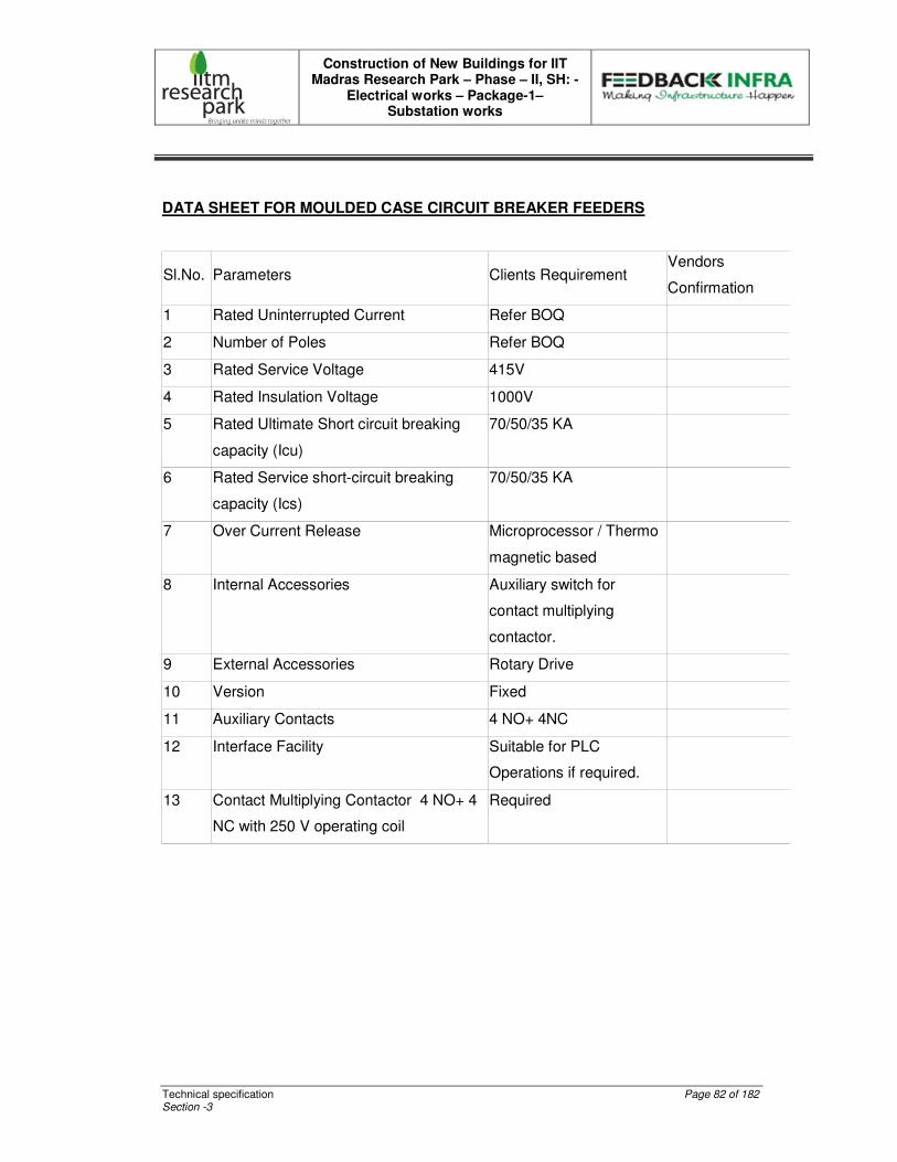
Construction of New Buildings for IIT Madras Research Park – Phase – II, SH: -
Electrical works – Package-1– Substation works
Technical specification Page 82 of 182 Section -3
DATA SHEET FOR MOULDED CASE CIRCUIT BREAKER FEEDERS
Sl.No. Parameters Clients Requirement Vendors
Confirmation
1 Rated Uninterrupted Current Refer BOQ
2 Number of Poles Refer BOQ
3 Rated Service Voltage 415V
4 Rated Insulation Voltage 1000V
5 Rated Ultimate Short circuit breaking
capacity (Icu)
70/50/35 KA
6 Rated Service short-circuit breaking
capacity (Ics)
70/50/35 KA
7 Over Current Release Microprocessor / Thermo
magnetic based
8 Internal Accessories Auxiliary switch for
contact multiplying
contactor.
9 External Accessories Rotary Drive
10 Version Fixed
11 Auxiliary Contacts 4 NO+ 4NC
12 Interface Facility Suitable for PLC
Operations if required.
13 Contact Multiplying Contactor 4 NO+ 4
NC with 250 V operating coil
Required
Construction of New Buildings for IIT Madras Research Park – Phase – II, SH: -
Electrical works – Package-1– Substation works
Technical specification Page 83 of 182 Section -3
LT TECHNICAL SPECIFICATION
SL.NO CONTENTS
1 IS SPECIFICATIONS
2 RISING MAINS
3 LT PANEL BOARDS
4 LT CABLES
5 CABLE TRAYS
6 DISTRIBUTION BOARDS
7 WIRING SYSTEM
8 LIGHT FITTING AND ACCESSORIES
9 CONDUIT
10 LIGHTNING ARRESTER
11 EARTHING
12 INSTALLATION
13 TESTING AND COMMISSIONING
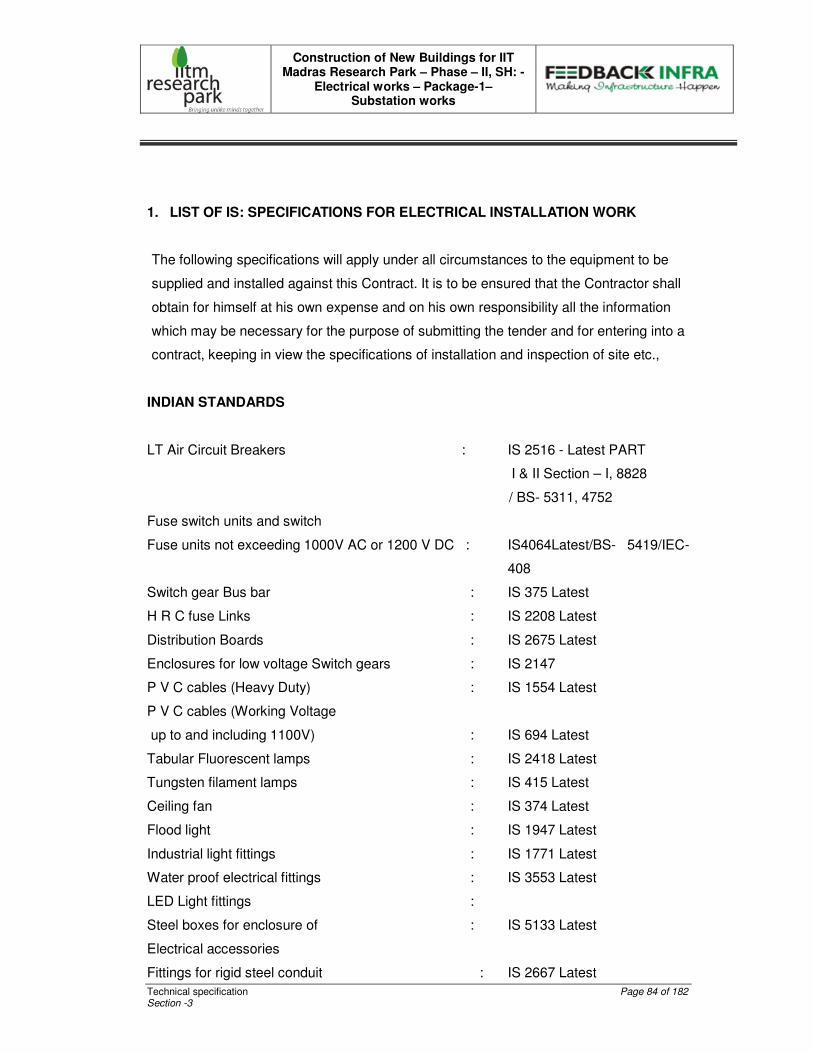
Construction of New Buildings for IIT Madras Research Park – Phase – II, SH: -
Electrical works – Package-1– Substation works
Technical specification Page 84 of 182 Section -3
1. LIST OF IS: SPECIFICATIONS FOR ELECTRICAL INSTALLATION WORK
The following specifications will apply under all circumstances to the equipment to be
supplied and installed against this Contract. It is to be ensured that the Contractor shall
obtain for himself at his own expense and on his own responsibility all the information
which may be necessary for the purpose of submitting the tender and for entering into a
contract, keeping in view the specifications of installation and inspection of site etc.,
INDIAN STANDARDS
LT Air Circuit Breakers : IS 2516 - Latest PART
I & II Section – I, 8828
/ BS- 5311, 4752
Fuse switch units and switch
Fuse units not exceeding 1000V AC or 1200 V DC : IS4064Latest/BS- 5419/IEC-
408
Switch gear Bus bar : IS 375 Latest
H R C fuse Links : IS 2208 Latest
Distribution Boards : IS 2675 Latest
Enclosures for low voltage Switch gears : IS 2147
P V C cables (Heavy Duty) : IS 1554 Latest
P V C cables (Working Voltage
up to and including 1100V) : IS 694 Latest
Tabular Fluorescent lamps : IS 2418 Latest
Tungsten filament lamps : IS 415 Latest
Ceiling fan : IS 374 Latest
Flood light : IS 1947 Latest
Industrial light fittings : IS 1771 Latest
Water proof electrical fittings : IS 3553 Latest
LED Light fittings :
Steel boxes for enclosure of : IS 5133 Latest
Electrical accessories
Fittings for rigid steel conduit : IS 2667 Latest
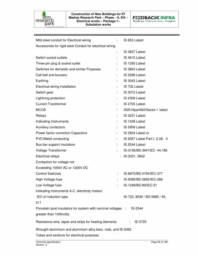
Construction of New Buildings for IIT Madras Research Park – Phase – II, SH: -
Electrical works – Package-1– Substation works
Technical specification Page 85 of 182 Section -3
Mild steel conduit for Electrical wiring : IS 653 Latest
Accessories for rigid steel Conduit for electrical wiring
: IS 3837 Latest
Switch socket outlets : IS 4615 Latest
Three pin plug & socket outlet : IS 1293 Latest
Switches for domestic and similar Purposes : IS 3854 Latest
Call bell and buzzers : IS 2268 Latest
Earthing : IS 3043 Latest
Electrical wiring installation : IS 732 Latest
Switch gear : IS 3072 Latest
Lightning protection : IS 2309 Latest
Current Transformer : IS 2705 Latest
MCCB : IS2516partI&II/Sector I latest
Relays : IS 3231 Latest
Indicating Instruments : IS 1248 Latest
Auxiliary contactors : IS 2959 Latest
Power factor correction Capacitors : IS 2834 Latest or
PVC/Metal conducting : IS 9357 Latest Part I, 2,3& 4
Bus-bar support insulators : IS 2544 Latest
Voltage Transformer : IS-3156/BS-3941IEC- 44,186
Electrical relays : IS-3231, 3842
Contactors for voltage not
Exceeding 1000V AC or 1200V DC
Control Switches : IS-6875/BS-4794/IEC-377
High Voltage fuse : IS-9385/BS-2692/IEC-269
Low Voltage fuse : IS-1248/BS-89/IEC-51
Indicating instruments A.C. electricity meters
IEC-of induction type IS-722, 8530 / BS-5685 / 45,
211
Porcelain post insulators for system with nominal voltages : IS-2544
greater than 1000volts
Resistance wire, tapes and strips for heating elements : IS-3725
Wrought aluminium and aluminium alloy bars, rods, and IS-5082
Tubes and sections for electrical purposes.
Construction of New Buildings for IIT Madras Research Park – Phase – II, SH: -
Electrical works – Package-1– Substation works
Technical specification Page 86 of 182 Section -3
Toggle switches : IS-3452/BS-3676
General requirement for switchgear and control gear : IS-4237/BS-5486/IEC-
439
for voltage not exceeding 1000 volts
Degree of protection provided by enclosures for low voltage: IS-2147/IEC-144
Switchgears and control gear
Dimensions for panel mounted indicating and : IS-2419
Recording electrical instrument
Marking and arrangement for switchgear, bus-bars, main : IS-375
Connection and auxiliary wiring.
Code of practice for selection, Installations and maintenance of : IS-10118 Fuses.
Code of practice for safety procedure in Electrical work : IS 5216 (Part-1): 1982
2. TECHNICAL SPECIFICATIONS FOR RISING MAIN
SCOPE This specification covers the technical requirements of Design, manufacture, test at works, supply of 415V, conventional type rising mains. STANDARDS
The equipment covered by this specification shall unless otherwise stated, be designed, constructed and tested in accordance with the latest revisions of relevant Indian Standards and shall conform to the regulation of local statutory authorities.
� IS 2147 : Degree of Protection provided enclosure � IS 8623(Part-II) : Particular requirements for Bus trunking system � IS 13947 (Part-3) : Specification for Low Voltage Switch gear and control
gear.
GENERAL
Bus Rising system shall be Non-segregated type and shall be supplied for the Sub Distribution of Electricity energy.
Bus Rising main shall have outgoing tap off boxes into the live bus and designed for feeding to the individual floor areas.
These systems shall be installed in side the electrical room.

Construction of New Buildings for IIT Madras Research Park – Phase – II, SH: -
Electrical works – Package-1– Substation works
Technical specification Page 87 of 182 Section -3
The supply of support materials like clamps, steel channel etc., shall also be included in the scope of this tender.
The bus bars shall be installed vertically supported from wall in the electrical room.
The rising main enclosure shall be dust and vermin proof, rectangular in cross section and shall be fabricated out of 2mm thick CRCA sheets. It shall be rigid and robust in construction and shall be treated to prevent any possibility of corrosion joints in the enclosure shall be bolted and shall be provided with neoprene gaskets. All retaining catches, screws, bolts and nuts etc., shall be cadmium plated.
The rising main shall be manufactured in standard lengths with arrangements for tap off boxes.
BUSBAR SYSTEM
The bus bars shall be air insulated and made up of Electrolytic grade Aluminium. The bus bars shall have a continuous current rating as mentioned in particular specification and shall have fault withstand capacity as specified in the Schedule of Quantities.
In their functional position, they shall be horizontally pluggable, on edge or flat, and in each position they shall be operable at continuous nominal current and at an ambient temperature of 45°C. The type of protection shall be IP42.
Earth bus bar section shall be provided with lugs on the outer casing suitable for connection to the main earthing system conductor.
Feeding System
All bus bar system shall be equipped with end or central feeder cabinet (as per site condition) with suitably rated MCCB. Necessary extension chambers to facilitate easy cable termination shall also be provided.
Expansion Joints
The bus bar system shall be equipped with standard flexible joints in every floor crossing (maximum 4.5 mtrs length) to compensate thermal elongation of the bus bars.
Construction of New Buildings for IIT Madras Research Park – Phase – II, SH: -
Electrical works – Package-1– Substation works
Technical specification Page 88 of 182 Section -3
As far as local conditions permit, the longest bus bar unit lengths shall be used to minimize electrical losses at the butt or bolted connections of the bus bars.
The bus bar junction points shall be marked with plastic, phenolic or aluminium labels.
Tap – Off Points
Tap of points shall be provided at every floor intervals on either side, to make connections to the live bus bars safely. These points shall be provided with safety shutters to prevent inadvertent touching of bus bars when no tap off box is fitted and to ensure that no foreign matter enters bus bar chamber. Provisions of slots for installing additional tap off boxes in future are to be provided in the rising main.
Accessories
All suspension fixings shall be fully tested and approved exclusively as suitable for the installation with particular regard to ambient temperature of 45 deg, environment and loading. The bus system shall be assembled from standard approved components completed at the factory and suitable for an application.
MOULDED CASE CIRCUIT BREAKERS
The MCCB shall comply with the requirement of IS 13947. The MCCB shall comprise of switching mechanism, contact system, arc extinguishing device and the tripping unit all mounted inside a moulded case. The MCCB shall be provided with field settable over load protection. MCCB shall employ quick make break switching mechanism independent of the speed of operation of the operating handle. The operating mechanism also is trip free. The operating handle shall have provision for door interlock and padlocking.
EARTHING
The rising main enclosure shall be earthed by a continious 1 set of 2 nos. High quality G.I ( not less than 80 microns) earth bar of 50X6 mm size, running on the out side of the enclosure throughout the entire length of the bus bar trunking.

Construction of New Buildings for IIT Madras Research Park – Phase – II, SH: -
Electrical works – Package-1– Substation works
Technical specification Page 89 of 182 Section -3
TESTS
Rising Main shall be completely assembled, adjusted and tested for operation under simulated conditions to ensure proper functioning of all equipments.
Types Tests
The Bidder shall furnish two (2) sets of type test certificates for all the tests conducted on similar equipment.
a) Short time current test. b) Temperature rise test. c) One-minute power frequency voltage withstand test.
Routine Tests
� Mechanical operation test. � Dielectric test.
Drawings and Documents The following drawings and documents shall be furnished in six (6) copies and get
approved before execution of work.
General arrangement drawing for rising main showing
� Overall Dimensions for Different rating � Terminal locations � Total weight/meter � Sectional views � Fixing details � Sectional view of Tap-off Box.
21. Single Line Diagram
22. Technical details for Fuse switches.
23. Manufacturing schedule and test schedule.
24. Calculation for bus bar sizing
25. O&M Manual.
26. Quality Assurance Plan
GUARANTEED TECHNICAL PARTICULARS FOR RISING MAINS
(TO BE FILLED IN BY THE TENDERER)
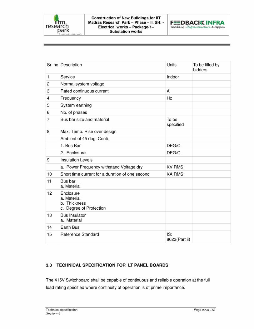
Construction of New Buildings for IIT Madras Research Park – Phase – II, SH: -
Electrical works – Package-1– Substation works
Technical specification Page 90 of 182 Section -3
Sr. no Description Units To be filled by bidders
1 Service Indoor
2 Normal system voltage
3 Rated continuous current A
4 Frequency Hz
5 System earthing
6 No. of phases
7 Bus bar size and material To be specified
8 Max. Temp. Rise over design
Ambient of 45 deg. Centi.
1. Bus Bar DEG/C
2. Enclosure DEG/C
9 Insulation Levels
a. Power Frequency withstand Voltage dry KV RMS
10 Short time current for a duration of one second KA RMS
11 Bus bar a. Material
12 Enclosure a. Material b. Thickness c. Degree of Protection
13 Bus Insulator a. Material
14 Earth Bus
15 Reference Standard IS: 8623(Part ii)
3.0 TECHNICAL SPECIFICATION FOR LT PANEL BOARDS
The 415V Switchboard shall be capable of continuous and reliable operation at the full
load rating specified where continuity of operation is of prime importance.
Construction of New Buildings for IIT Madras Research Park – Phase – II, SH: -
Electrical works – Package-1– Substation works
Technical specification Page 91 of 182 Section -3
The LV Breaker shall be capable of withstanding the severest stresses likely to occur in
actual service and of resisting rough handling during transport.
Note: Integration includes supply of materials like Meters, CTs, Bus bars, Insulators,
Indicating Lamps, Metering Fuses, etc.,
STANDARDS
The Tenderer shall control the quality of items and services to meet the requirements of
this specification, applicable codes and standards and other procurement documents.
The LV Panel Boards shall comply with the latest issue of the following standards.
IS 8623 – General requirement for factory built assemblies upto 1000 Volts.
IS 13947-2 – A.C. Circuit breaker requirements – Voltage not exceeding 1000Vs
Part I & II, Sec 1 and IEC 60947 part I & III
IS 2705 – Specification for current transformers
IS 1248 – Specification for direct acting electrical indicating instruments.
IS 3156 – Voltage transformers
IS 3231 – Relays
IS 13703 – Specification for HRC cartridge fuse links upto 650 Volts.
IS 11353 – Marking and identification of conductors and apparatus
IS 13947 – Part I & II – Moulded Case Circuit Breaker
IS 6005 – Code of practice for phosphating Iron and Steel
IS 5082 – Wrought Aluminium & Aluminium Alloy for Electrical Purposes
IS 60947-6-1-Automatic transfer switch
CONSTRUCTION
The LT Panels shall be of, Metal enclosed, indoor, floor mounted self standing type,
compartmentalized, top/bottom entry as specified in the BOQ.

Construction of New Buildings for IIT Madras Research Park – Phase – II, SH: -
Electrical works – Package-1– Substation works
Technical specification Page 92 of 182 Section -3
Made up of the requisite vertical sections, which when coupled together shall form
continuous dead front switchboards.
The LV Panels shall be of dust and vermin proof of MS sheet steel enclosure with
degree of protection IP 54.
The panel shall be readily extensible on both sides by the addition of vertical sections
after removal of the end covers. The main buabars shall have slotted holes on both the
sides for easy extension.
The panels shall be constructed only of materials capable of withstanding the
mechanical, electrical and thermal stresses as well as the effects of humidity, which are
likely to be encountered in sea shore areas.
Each vertical section shall comprise: -
A front-framed structure of rolled/folded sheet steel channel section, of minimum 14SWG
thickness, rigidly bolted together. This structure shall house the components contributing
to the major weight of the equipment, such as Air circuit breaker cassettes, MCCB’s ,
main horizontal bus bars, vertical risers and other front mounted accessories.
The structure shall be mounted on a rigid base frame of folded sheet steel of minimum
3mm thickness and 100mm height or equivalent MS channels. The design shall ensure
that weight of the components is adequately supported without deformation or loss of
alignment during transit.
The design shall ensure generous availability of space for termination and maintenance
of cabling, and adequate safety for working in one vertical section without coming into
accidental contact with live parts in an adjacent section.
A cover plate at the top of vertical section, provided with ventilating hood where
necessary aperture for ventilation shall be covered with a perforated sheet to prevent
entry of vermin.
Front doors and rear covers fitted with dust excluding synthetic rubber gaskets with
fasteners designed to ensure proper compressions of gaskets. When covers are

Construction of New Buildings for IIT Madras Research Park – Phase – II, SH: -
Electrical works – Package-1– Substation works
Technical specification Page 93 of 182 Section -3
provided in place of doors, generous overlap shall be assured between sheet steel
surface with closely spaced fasteners to preclude the entry of dust.
The height of the panel shall not be more than 2100mm. The total depth of the panel
should be adequate to cater for proper cabling space and shall not exceed 1200mm for
ACB sections.
Doors shall be minimum 14SWG sheet steel. Sheet steel shrouds and partitions shall be
of minimum 16SWG thickness. All sheet steelwork forming the exterior of switchboards
shall be smoothly finished, leveled and free from flaws. The corners should be rounded.
All insulating material used in the construction of the equipment shall be of non-
hygroscopic material, duly treated to withstand the effects of high humidity(Chennai
climate), high temperature tropical ambient service conditions.
Metallic / Insulated barriers / Hylum Shrouding shall be provided within vertical sections
and between adjacent sections to ensure prevention of accidental contact.
All doors/covers providing access to live power equipments circuits shall be provided tool
operated fasteners to prevent unauthorized access.
Provision shall be made for permanently earthing the frames, doors and other metal part
of the switchgear by two independent connections.
Operating devices shall be incorporated only in the front of the switchgear. No handle
shall be located more than 450mm and not higher than 1800mm above finished floor
level.
Suitable eyebolt for lifting of panel shall be provided.
BUSBARS
The bus bars shall be air insulated and made of high conductivity, high strength, 99.99%
Pure Electrolytic grade Aluminium.
A current density of 0.8 A / Sq. mm. shall be considered for Aluminium bus bars. For
Main distribution Boards the size of bus bars shall be designed on the basis of a short
Construction of New Buildings for IIT Madras Research Park – Phase – II, SH: -
Electrical works – Package-1– Substation works
Technical specification Page 94 of 182 Section -3
circuit rating of 50kA for 1 sec and for other sub distribution boards the bus bars shall be
designed for 35kA and 25kA as indicated in SLD.
The bus bars shall be suitably braced with non-hygroscopic SMC supports, the neutral
as well as the earth bar should also be capable of withstanding the stress of electrical
fault. Ridges shall be provided on the SMC supports to prevent tracking between
adjacent bus bars.
As per standards large clearances and Creepage distances shall be provided on the bus
bars system to minimize the possibility of a fault.
High tensile bolts and star washers shall be used to minimize the possibility of a fault.(
Spring washers of split type not permitted)
Connections from the main bus bars to functional circuits shall be arranged and
supported so as to withstand without any damage or deformation the thermal and
dynamic stresses due to short circuit currents.
Apparatus forming part of the panel shall have the following recommended minimum
clearances for an insulated bus bars or should as per relevant IS code 4237 – 1967.
Between phases – 25mm
Between phases and neutral – 25mm
Between phases and earth – 19mm
Between neutral and earth – 19mm
For lengthy bus bars suitable expansion joints shall be provided. (The length beyond
4.5m shall be provided with necessary flexible connectors for bus expansion and
contraction. The flexible material shall be same as that of bus bar to avoid bimetallic
reaction).
The main bus bar shall have uniform current ratings through their length. The current
rating of the neutral shall be equal of the size that of the phase bus bars throughout the
length of the switchboard.
Construction of New Buildings for IIT Madras Research Park – Phase – II, SH: -
Electrical works – Package-1– Substation works
Technical specification Page 95 of 182 Section -3
However for the UPS Panels, the Neutral Bus bars shall be Double the size of Phase
bus bar. Removable neutral links shall be provided on feeders to permit isolation of the
neutral bus bar.
The size of the branch busbar shall be suitable to withstand the panel fault level and also
the current rating of that particular branch.
The bus bar and supports shall be capable of withstanding 35kA Short circuit current at
415 V for 1 Sec in the LT panels and 25kA for Sub Panels.
Only zinc passivated or cadmium plated high tensile strength steel bolts, nuts and
washers shall be used for all bus bar joints and supports. All bus bar supports shall be
SMC only.
All bus bars shall be colour coded by means of identifying colour rings at every power tap
off point. Red, yellow and blue colour shall be used for Phase bus bars and Black
colour shall be used for neutral bus bars. Each bus bar shall be insulated with heat
shrinkable colored PVC sleeves.
The Bus bars shall be capable of withstanding rated capacity without any deration at
70°C.
The rating of bus bars shall be same as that of incomer breaker rating.
Bus bars shall be housed in a separate chamber, which shall be accessible for inspection
when it is required. The Bus bar chambers shall have bolted cover only and hinged doors
are not permitted. Wherever hinged doors are used suitable insulation barriers are to be
provided to avoid accidental contacts of live parts.
POWER CONNECTIONS
Interconnection of various switchgear components with the main bus bars, shall be done
with bus bars or cables for 63 Amps and less. The inter connectors shall be directly
Construction of New Buildings for IIT Madras Research Park – Phase – II, SH: -
Electrical works – Package-1– Substation works
Technical specification Page 96 of 182 Section -3
mounted on the bus bar and to be tightened to the recommended torque for a firm &
reliable connection, using specified tools on the bus bar.
All components (Bus bars, inter connections, switchgear components etc.) shall be
mounted based on open system.
Heavy duty terminal blocks to be adequately provided to take outputs from the
switchgear components, with suitable size of cable.
The cable entry shall be top / bottom as per BOQ.
All components (Bus bars, connection adaptor, component adaptor, supports, switchgear
components etc.) shall be mounted based on open system.
Terminal blocks to be adequately provided to take outputs from the switchgear
components, with suitable size of cable.
TECHNICAL SPECIFICATIONS FOR DMC / SMC
PROPERTIES UNITS TEST METHODS
(ASTM) VALUES
SMC DMC
PHYSICAL
Specific Gravity gm/cc D-792 1.7 1.9
Glass Contents % N.A 25 15
Water Absorption % D-570 0.2 0.15

Construction of New Buildings for IIT Madras Research Park – Phase – II, SH: -
Electrical works – Package-1– Substation works
Technical specification Page 97 of 182 Section -3
MECHANICAL
Tensile Strength Kg/Sq. cm D-638 700 400
Flexural Strength Kg/Sq. cm D-790 1550 900
Compressive Strength Kg/Sq. cm D-695 1800 1500
Impact Strength Kg cm / Sq. cm D-256-A 60 25
ELECTRICAL
Dielectric Strength KV/mm D-149 12 10
Tracking Index Volts BS-5901 +600 +600
Arc Resistance Secs. D-495 +800 +800
COMPONENTS
AIR CIRCUIT BREAKER
ACB shall confirm to 60947 (Part I & III) / IS 13947 (Part I & III)
Suitable for a service voltage of 3 Phase, 415 V minimum, 50 Hz AC supply and shall
have an insulation voltage of 1000 V.
Possible to upgrade the degree of protection of ACB to IP : 55. Minimum degree of
protection of the ACB shall be IP : 43.
Suitable for front and rear access.
The ACB shall have the following inbuilt protections with microprocessor based / thermal
magnetic releases as specified in BOQ.
1. Overload
2. short circuit
3. Earth fault
4. Instantaneous
5. Under and over voltage protections
INTERLOCK AND SAFETY ARRANGEMENT
Construction of New Buildings for IIT Madras Research Park – Phase – II, SH: -
Electrical works – Package-1– Substation works
Technical specification Page 98 of 182 Section -3
The ACB's shall be Four pole draw out type. ( Electrical or Manual type specified in
SLD)
Any attempt to with draw the Air Circuit Breaker, when the unit is in service, will
automatically trip the breaker. It shall be possible to rack the ACB to disconnected
position with the door closed.
Remote electrical indication of the circuit breaker status should be possible for all the
positions.
Possible to close the ACB electrically and the spring charging time shall be preferably by
less than 5 seconds. The mechanism shall be of stored energy type. The electrical
closing mechanism shall have a built- in anti pumping feature minimum 6 NO & 6 NC
control contacts should be available for external use.
RATING AND BREAKING CAPACITY
The ACB shall have Minimum Service Breaking Capacity (Ics) equal to Ultimate Breaking
Capacity (Icu).
The Minimum Service Breaking Capacity (Ics) for 1600/800/630 AMPS is 50KA or as
specified in SLD
PROTECTION
There shall be an option to select the curves (minimum 80 combinations) and also
change the operating time for minimum of 8 settings for overload, 7 for short circuit and 7
settings for earth fault.
There shall be facility for selecting various type of E/F protection if required.
Trip history feature shall be available in micro processor based trip units.
Neutral protection of 50 to 100% shall be available.
Self - diagnostic malfunction alarm for microprocessor should be available.
Construction of New Buildings for IIT Madras Research Park – Phase – II, SH: -
Electrical works – Package-1– Substation works
Technical specification Page 99 of 182 Section -3
"The trip unit shall have thermal memory.
I2 t cropping facility shall be available for short circuit and earth fault.
Fault indication by means of LED should be available for Overload, Short Circuit and
Earth Fault and also LCD display for indication of menu's, settings, recorded information.
Trip reset facility should be manual / automatic.
It shall be possible to trip (or) close the Breaker through RS 485 communication interface
if specified.
AUTOMATIC TRANSFER SWITCH
ATS should comply with IS/IEC:60947-6-1
Automatic transfer from main supply to standby supply is vital for all the critical loads. In
the event of power failure the standby power is usually expected to take over
automatically. Electrical starting equipment, battery bank and diesel generator are
required for the automatic operation. The automatic tranferis achieved by automatic
mains failure systems. The process of onload transfer has to be monitored & controlled
for a smooth changeover and within safety limits of all elements of the system. This can
be achieved by Automatic Transfer Switch(ATS)
ATS shall have the following features:
1. High speed transfer
2. Superior making & breaking capacity
3. Compact & light weight design
4. Positive indication through flag indicator
5. Neutral point transfer
6. Liberal terminals
7. Phase barriers
The following are the guaranteed technical particulars

Construction of New Buildings for IIT Madras Research Park – Phase – II, SH: -
Electrical works – Package-1– Substation works
Technical specification Page 100 of 182 Section -3
Sl no Parameters Units Clients requirement
Vendor's confirmation
1 Rated operating current Ie Amps As per BOQ
2 No of poles 4P
3 Rated operating voltage Volts 415
4 Insulation voltage Volts 1000 V
5 Utilization category AC 31A
6 Dielectric strength KV 5
7 Impulse withstand voltage Uimp KV 8
8 Rated making capacity at 0.8 pf Amps 10xIe
9 Rated breaking capacity 0.8 pf Amps 8 xIe
10 Rated short time withstand capacity Amps specify
11 Rated short time making capacity Amps specify
12 Mech life no of operation specify
13 Electrical life no of operation specify
14 Switching frequency operation per hour
specify
15 Operating voltage Volts 230 volts
16 Change over time min 0.1 m sec
17 Change over time max 60 sec
MOULDED CASE CIRCUIT BREAKER
MCCBs should comply with IEC 947 Part 2. / IS 13947
The MCCB shall be suitable for universal mounting (i.e) the Load / Line must be
interchangeable.
The MCCB shall be suitable for operating Voltage of 415 V minimum and an Insulation
Voltage of 690 V.
Rating and Breaking Capacity
The Service Breaking Capacity (Ics) in KA for MCCB shall be as specified in SLD: -
PROTECTION

Construction of New Buildings for IIT Madras Research Park – Phase – II, SH: -
Electrical works – Package-1– Substation works
Technical specification Page 101 of 182 Section -3
Overload and short circuit setting details:-
All outgoing MCCBs in the Main distribution boards and incoming MCCBs of all Sub
distribution panel boards shall be of adjustable overload and short circuit protection
settings.
The outgoing MCCBs in the Sub Panels needs adjustable thermal overload settings only
and fixed short circuit setting.
The Thermal setting shall be adjustable from 40% to 100% of its normal current.
The magnetic setting shall be continuously adjustable from 6 to 10 times of its set
current.
Trip reset should be available Manual / Automatic.
Note: If specifically mentioned in SLD or BOQ microprocessor based MCCBs shall be
provided
CONTACTORS
Contactors shall comply with IS 13947 for general rules and IS13947-4-1 for standards
pertaining to contactors and motor starters. The contactor shall be capable of
withstanding breaking & making capacities as follows:
AC3 Category
Making Current - 10 times Rated Current
Breaking current - 8 times Rated current
Contactor shall be capable of withstanding an impulse voltage of 8 KV and have an
insulation voltage of 1000V.
The Contactors shall be capable of frequent switching and should operate without any
deration at 55 ° C for AC3 application.
Construction of New Buildings for IIT Madras Research Park – Phase – II, SH: -
Electrical works – Package-1– Substation works
Technical specification Page 102 of 182 Section -3
The coil shall be of suitable voltage of control circuit proposed and the insulation class
shall be preferably H class, to sustain frequent switching operations. The auxiliary
contact block shall have a switching capacity of 240V at 2A. Contactors shall have one
auxiliary in-built and it shall be possible to have additional NO & NC contacts in steps of
two. The contactors for the capacitors shall be of capacitor duty.
THERMAL OVERLOAD RELAY
The Thermal Overload Relay shall comply with IS 13947-1 for general rules and IS
13947-1 for standards pertaining to contactor shall be designed for AC3.
The Thermal Over Load Relay shall be suitable for and Type 2 coordination as per
suitable clause in the relevant Indian Standards.
The Thermal Overload Relay shall be capable of offering single phasing protection and
shall be ambient compensated type, operable up to 70 ° C.
The Thermal Overload Relay shall be capable of withstanding short circuit equal to
fifteen times the rated thermal current (15 Ie).
It shall be possible to mount the Thermal Overload Relay on the underside of the
contactor directly.
The design of the terminal shroud shall be such that it offers complete protection against
direct finger contact with the power terminal, as under IP 20 protection.
The Thermal Overload Relay shall have in built 4NO & 4NC contact.
The “Reset” operation shall be clearly distinguished from the “Stop” operation.
The Thermal Overload Relay shall have separate “Stop” and “Test” button.
The setting shall be of the adjustable type and there should be a provision of sealing to
make the same tamper proof.
Construction of New Buildings for IIT Madras Research Park – Phase – II, SH: -
Electrical works – Package-1– Substation works
Technical specification Page 103 of 182 Section -3
Thermal Overload Relay shall be suitable for Aluminum termination, with a maximum
permissible temperature rise of 65 deg at the terminals, with an ambient temperature of
45 °. C.
WIRING
Power, control, signaling, protection and instrument circuits shall be done with PVC
Insulated FRLS multi strand copper conductors. The insulation grade for these wires
shall be 600 volts. All control wiring shall preferably be enclosed in plastic channels or
neatly bunched together.
For control circuits, 1.5 Sq. mm size wires shall be used. Each wire shall be terminated
at a separate terminal. Termination of two outgoing wires on a single terminal will not be
acceptable. Wires shall not be joined or tied between terminal parts. Shorting links shall
be provided for all C.T. Terminals. For CT circuits 2.5 sq mm wires shall be used.
Each wire shall be identified at both ends by self-sticking wire marker tapes or PVC
Ferrules. Ferruling of wires shall be as per relevant IS.
A minimum of 10% spare terminals shall be provided on each terminal block. Conductors
shall be terminated with adequately sized compression type lugs. "ELMEX" type (direct
conductor termination) type terminals will be acceptable for wires upto 10 sq. mm.
The control terminals shall be mounted in such a way that they are separate from the
power terminals and shall be easily accessible without any hindrance from the power
circuitry.
The wiring shall be complete in all respects so as to ensure proper function of control,
protection and interlocking schemes.
CURRENT TRANSFORMERS
Current Transformers shall be tape wound . The CT ratio and VA burden shall be such
that it can power all meters.
Current transformers shall generally conform to IS: 2705.
Construction of New Buildings for IIT Madras Research Park – Phase – II, SH: -
Electrical works – Package-1– Substation works
Technical specification Page 104 of 182 Section -3
Current transformers for instruments shall have an accuracy class 0.5 for LT Panels
and accuracy limit factor less than 5.0.
The current transformers shall be capable of withstanding the peak momentary short
circuit current for 1.0 second.
The neutral side of the current transformers shall normally be earthed through a link.
MEASURING INSTRUMENTS
All measuring instruments shall be of flush mounting, digital type and the size of
indicating instruments shall be 96 x 96 Sq. mm. All energy meters shall be of dual
source type and have RS 485 port.
The display shall be multiform LCD display with back lit.
The accuracy class of the meters shall be 0.5.
The meter should conform to IEC 61557-12.
INDICATING LAMPS
Indicating lamps shall be of LED type, low watt consumption, provided with series
resistor where necessary and with translucent lamp covers. Bulbs and lenses shall be
easily replaceable from the front.
Following Indicating Lamps are required on the panel having lens colours as detailed
below :
RYB Indication Lamps : RED, YELLOW, BLUE
Breaker ON : RED
Breaker OFF : GREEN
Auto Trip : AMBER
SURGE ARRESTORS
Construction of New Buildings for IIT Madras Research Park – Phase – II, SH: -
Electrical works – Package-1– Substation works
Technical specification Page 105 of 182 Section -3
SWITCHING SURGE PROTECTION FOR RISING MAINS.
C type surge arrestors shall be provided for rising mains incomers in suitable metal
boxes.
It should be a plug in type arrestor with a dynamic separating device.
CABLE TERMINATIONS
The cabling chamber and bus chamber shall be openable from front only. Adequate size
for accommodation, support and termination of Copper / Aluminium cables shall be
provided at front side. Proper cable clamping arrangements shall be provided.
Detachable gland plate of 3 mm thickness shall be provided for the cable entry into the
panel. Cable entry shall be top/bottom as speecified.
LABLES
Every switchboard, switchboard control contactor, time switch, relay, indicator lamp,
meter, motor starter, link and any control or protection equipment within or on a
switchboard shall be clearly and accurately labeled.
Labels shall be engraved laminated plastic or photo anodized rigid aluminum and shall
comply with the following requirements.
Except where otherwise required labels shall be fixed adjacent to, but not on any item of
equipment.
Engraved lettering shall be white on a black background, except that the label for a main
switch shall have red lettering on a white background, and warning and caution labels
shall have white lettering on a red background.
Labels shall be securely fixed by Screws and adhesive, are fixed in an extruded
aluminum section which shall be countersunk screw fixed or countersunk riveted to the
panel. Screws shall be tightened with nuts or into tapped holes in the switchboard.
Mechanically expanded plastic rivets of minimum 6 mm. head diameter are acceptable
instead of screws. Aluminum rivets may be used to fix aluminum labels only. Self –
tapping screws, thread – cutting screws or other fixing are not acceptable.
Construction of New Buildings for IIT Madras Research Park – Phase – II, SH: -
Electrical works – Package-1– Substation works
Technical specification Page 106 of 182 Section -3
LABELS ON EXTERIOR OF SWITCHBOARDS
All switchboards shall be labeled with the manufacture’s name. A switchboard
designation label shall be provided. Engraved letter shall be Black background with
white lettering. For other than main switchboards, the designation label shall also state
the source of electrical supply.
Separate sections of enclosures shall be identified. The label for any section or
enclosure containing supply Authority equipment shall be to the satisfaction of the Client /
Consultant. Every switchboard control shall be labeled and shall include:
Circuit designation for all main switches, main controls and sub main controls. Details of
the Consumer’s mains and all sub mains, Incoming bus bar or cable rating. The
minimum height of lettering shall be 6mm.
EARTHING
Switchgears in the panel shall be provided with double earth connection of size indicated
in the schedule and connected to the earth bus.
Earth bus bar shall be supported at regular intervals.
All instruments and metering panel doors shall be connected to earth by using 2.5 sq.
mm. 600V, FRLS PVC multi stranded copper conductor or flexible braided copper wire
of equivalent size and directly connected to the earth bus of the panels
The materials and size of the earth bus bar shall be as specified in the BOQ. At either
end of the earth bus provision shall be made for bolting the earth bus to the earth
electrode with nuts & bolts and star washer. The earth bus bar shall run along the entire
length of the board.
PAINTING
All metal surfaces shall be chemically cleaned, degreased and pickled in acid to produce
a smooth clean surface, free of scale, grease and rust.
Construction of New Buildings for IIT Madras Research Park – Phase – II, SH: -
Electrical works – Package-1– Substation works
Technical specification Page 107 of 182 Section -3
After cleaning, phosphating and passivation treatment, the panel shall be given matt
finish powder coating suitable for out door applicatiion with RAL 7032 in light gray
minimum of 60 to 70 microns. Sufficient quantity of touch up paint of the same colour
shall be furnished for application at site.
GENERAL
Inter panel partitions / barriers in sheet steel are required to be provided.
Bus bar joint shrouds are required to be provided and shall be of clip – on type reusable
so that it can be easily removed and refitted.
All internal wiring shall be done with crimping type lugs and all terminals are to be
identified / ferulled properly.
All vacant compartments above 100mm to be provided with earth strip. “Danger” labels
on rear doors shall be provided.
Necessary terminals are to be provided for BMS interface at all Panels. Data sheet shall
be referred for specification of the ACB & MCCB to be used in panels.
No alterations drill holes welding etc., are to be done at site after the panel boards are
received from the factory.
The panel boards shall complete with all rules & regulations as per CEIG / CEA
norms and any modifications pointed out by them or any other statuary agencies
after commissioning also to be carried out and completed at free of cost. The
panel fabricator shall have a valid CPRI test certificate for short circuit rating.
INSPECTION
Fully assembled Panel boards shall be offered for inspection at works. Materials shall be
dispatched to site only after issuing the dispatch clearance by the representative of client
/consultants.
Stage 1 Inspection : During Assembly of Panel
Stage 2 Inspection : Before Dispatch
Construction of New Buildings for IIT Madras Research Park – Phase – II, SH: -
Electrical works – Package-1– Substation works
Technical specification Page 108 of 182 Section -3
The readiness should be informed at least fifteen days before the proposed date of
Inspection.
TESTS
The Panel design shall have undergone all the type tests as per IS: 8623. Type test
certificate shall be submitted along with the panels.
VISUAL TESTS
36. Corrosion test
37. Paint inspection
38. Physical verification check
39. Rubber gasket test.
40. Megger & High voltage Test.
COMMISSIONING
Pre-commissioning Checks and Tests shall be conducted at site by you at free of cost
and certificate shall be furnished.
The supplier shall render the service of his supervisor during the Installation and
commissioning of the panels by other agency at free of cost.
The quoted price shall be inclusive of all necessary commissioning spares.
DRAWINGS AND MANUALS
Vendors shall furnish the following drawings for Client / Consultant approval before
fabrication of the panel.
Tenderer shall also provide detailed GA diagram, sectional drawings, control wiring
diagram, Terminal drawings and other drawings with all dimensions indicating
Construction of New Buildings for IIT Madras Research Park – Phase – II, SH: -
Electrical works – Package-1– Substation works
Technical specification Page 109 of 182 Section -3
compartments cutouts, drill holes etc ., for all the panel boards to the Client /
Consultant
Front and rear view of all switch boards indicating Switch Gear arrangements of
Various feeders/starters giving its location numbers and tag numbers for each as per
single line diagram.
Typical control schematic diagram for each type giving type designation to be referred
on Single line diagram.
Switch board foundation/fixing details with all dimensions and details of shipping
sections. All the catalogues, manuals pertaining to each and every ACB, MCCB, Meters,
Relays, CTs etc should be sent along with the panel boards.
Bill of Materials used in panels indicating the make of each items
Manufacturers and service providers address, contact person, contact no etc., has to be
sent to us for all the components.
SPARES AND TOOLS
The commissioning and maintenance spares required for installing the LV Switch board
shall be quoted separately.
The tools required for the LV Switch boards also to be listed and quoted separately.
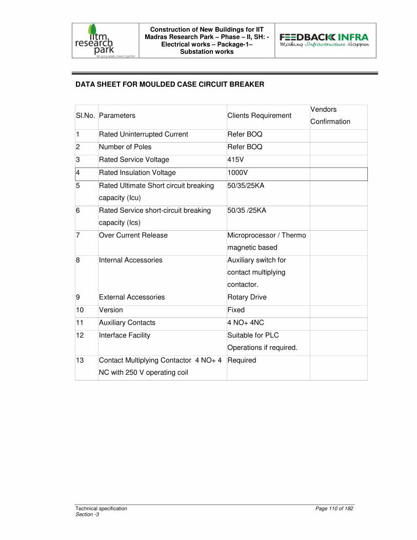
Construction of New Buildings for IIT Madras Research Park – Phase – II, SH: -
Electrical works – Package-1– Substation works
Technical specification Page 110 of 182 Section -3
DATA SHEET FOR MOULDED CASE CIRCUIT BREAKER
Sl.No. Parameters Clients Requirement Vendors
Confirmation
1 Rated Uninterrupted Current Refer BOQ
2 Number of Poles Refer BOQ
3 Rated Service Voltage 415V
4 Rated Insulation Voltage 1000V
5 Rated Ultimate Short circuit breaking
capacity (Icu)
50/35/25KA
6 Rated Service short-circuit breaking
capacity (Ics)
50/35 /25KA
7 Over Current Release Microprocessor / Thermo
magnetic based
8 Internal Accessories Auxiliary switch for
contact multiplying
contactor.
9 External Accessories Rotary Drive
10 Version Fixed
11 Auxiliary Contacts 4 NO+ 4NC
12 Interface Facility Suitable for PLC
Operations if required.
13 Contact Multiplying Contactor 4 NO+ 4
NC with 250 V operating coil
Required
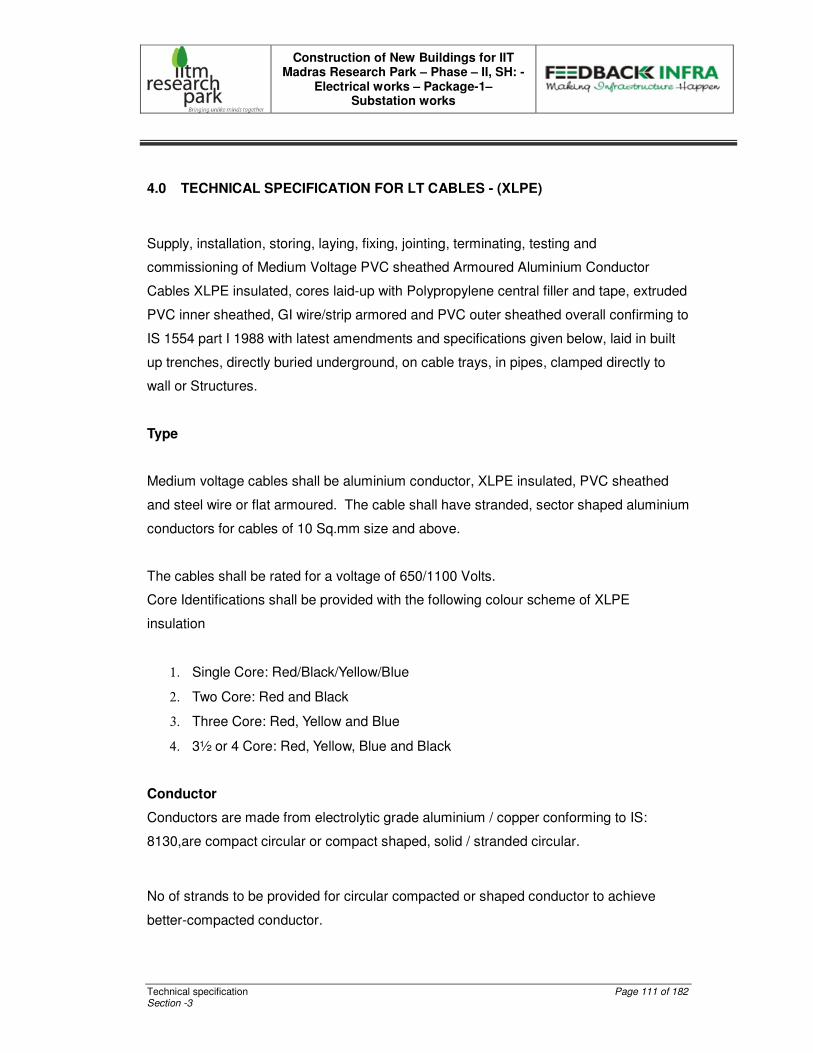
Construction of New Buildings for IIT Madras Research Park – Phase – II, SH: -
Electrical works – Package-1– Substation works
Technical specification Page 111 of 182 Section -3
4.0 TECHNICAL SPECIFICATION FOR LT CABLES - (XLPE)
Supply, installation, storing, laying, fixing, jointing, terminating, testing and
commissioning of Medium Voltage PVC sheathed Armoured Aluminium Conductor
Cables XLPE insulated, cores laid-up with Polypropylene central filler and tape, extruded
PVC inner sheathed, GI wire/strip armored and PVC outer sheathed overall confirming to
IS 1554 part I 1988 with latest amendments and specifications given below, laid in built
up trenches, directly buried underground, on cable trays, in pipes, clamped directly to
wall or Structures.
Type
Medium voltage cables shall be aluminium conductor, XLPE insulated, PVC sheathed
and steel wire or flat armoured. The cable shall have stranded, sector shaped aluminium
conductors for cables of 10 Sq.mm size and above.
The cables shall be rated for a voltage of 650/1100 Volts.
Core Identifications shall be provided with the following colour scheme of XLPE
insulation
1. Single Core: Red/Black/Yellow/Blue
2. Two Core: Red and Black
3. Three Core: Red, Yellow and Blue
4. 3½ or 4 Core: Red, Yellow, Blue and Black
Conductor
Conductors are made from electrolytic grade aluminium / copper conforming to IS:
8130,are compact circular or compact shaped, solid / stranded circular.
No of strands to be provided for circular compacted or shaped conductor to achieve
better-compacted conductor.
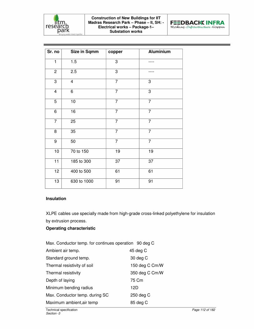
Construction of New Buildings for IIT Madras Research Park – Phase – II, SH: -
Electrical works – Package-1– Substation works
Technical specification Page 112 of 182 Section -3
Sr. no Size in Sqmm copper Aluminium
1 1.5 3 ----
2 2.5 3 ----
3 4 7 3
4 6 7 3
5 10 7 7
6 16 7 7
7 25 7 7
8 35 7 7
9 50 7 7
10 70 to 150 19 19
11 185 to 300 37 37
12 400 to 500 61 61
13 630 to 1000 91 91
Insulation
XLPE cables use specially made from high-grade cross-linked polyethylene for insulation
by extrusion process.
Operating characteristic
Max. Conductor temp. for continues operation 90 deg C
Ambient air temp. 45 deg C
Standard ground temp. 30 deg C
Thermal resistivity of soil 150 deg C Cm/W
Thermal resistivity 350 deg C Cm/W
Depth of laying 75 Cm
Minimum bending radius 12D
Max. Conductor temp. during SC 250 deg C
Maximum ambient,air temp 85 deg C
Construction of New Buildings for IIT Madras Research Park – Phase – II, SH: -
Electrical works – Package-1– Substation works
Technical specification Page 113 of 182 Section -3
Inspection
All cables shall be inspected upon receipt at site and checked for any damage during
transit and shall be supplied with complete manufacturer’s test certificates. At any cost
the cables shall not be accepted without test certificate.
Storing
All the cables shall be supplied in drums, with manufacturer’s seal. On receipt of cables
at site, the cables shall be inspected and stored in drums with flanges of the cable drum
in vertical position.
Joints in Cables
The Contractor shall take care to see that all the cables received at site are apportioned
to various locations in such a manner as to ensure maximum utilization and avoidance of
cable jointing.
This apportioning shall be got approved by the Consultant before the cables are cut to
lengths.
Where joints are unavoidable, the Consultant shall approve the location of such joints
and marking shall be done with suitable tags.
Jointing Kits for Cables
Cable joint kits shall be of appropriate size, suitable for XLPE insulated armoured cables
of particular voltage rating.
Joining Cables
All cable joints shall be made in suitable, approved cable joint kits, and the filling in of
compound shall be done in accordance with manufacturers’ instructions and in an
Construction of New Buildings for IIT Madras Research Park – Phase – II, SH: -
Electrical works – Package-1– Substation works
Technical specification Page 114 of 182 Section -3
approved manner. All straight through joints shall be done in epoxy moulding kits with
epoxy resin.
All cables shall be jointed colour to colour (inter changing of phases like Red phase to Y
phase is not permitted); tested for continuity and insulation resistance before jointing.
The seals of cables must not be removed until preparations for jointing are completed.
Joints shall be commenced and finished on the same day. During the time of joining the
cables, sufficient protection from the weather shall be ensured. Joints shall be made by
means of suitable ferules for conductors, the conductors being firmly butted into the
connections or thimbles or ferrules and the whole properly crimped using hydraulic
crimping. The conductors shall be efficiently insulated with high voltage insulating tape
and by using of spreaders of approved size and pattern. The joints shall be completely
topped up with epoxy compound so as to ensure that the box is properly filled.
Bonding of Cables
Where a cable enters any piece of apparatus, it shall be connected to the casing by
means of an approved type of armoured clamp and gland. The clamps must grip the
armouring firmly to the gland or casing, so that no undue stress is passed on to the cable
due to vibrations.
The glands shall be fixed to the armour, capable of being compressed. The gland or
cone shall be capable of affecting a good electrical bond between both the armouring of
the cable, and the gland.
Laying of Cables
Cables shall be laid as per the specifications given below:
Cables - Indoor
The cables laid indoors should be laid on galvanized steel cable trays supported on M.S.
angles. The cable trays should be routed above false ceilings wherever provided.
Suitable clamping with straps and saddles shall be used for keeping the cables in
position. Spacing between the cables shall not be less than the overall diameter of the
cable.

Construction of New Buildings for IIT Madras Research Park – Phase – II, SH: -
Electrical works – Package-1– Substation works
Technical specification Page 115 of 182 Section -3
In some cases special type of cable trays will be specified in the BOQ and the consultant
may be contacted for any clarifications.
The cables on wall surface from panel board up to angle iron shall run in galvanized
steel pipes of adequate size.
The Cables run inside concrete trenches shall be supported on cable trays and shall be
neatly arranged and clamped.
The Cable entries through pipes from outside to inside the building shall run in GI pipes
and shall be sealed water tight with approved type of sealant to avoid water entering the
building.
TESTS
The cables shall be tested in accordance with the IS: 694/1554/7098. The tests shall
include
PVC insulated cables (for voltage up to 1100V:IS 694
PVC insulated cables (heavy duty): IS 1554 – Part I.
Cross-linked polyethylene insulated PVC sheathed cables: IS 7098 – Part I.
Cable Insulation Tests shall be conducted between phases and between phase and
earth for each length of cable, before and after jointing.
As such all phase cables may be checked before being laid for above tests. On
completion of cable laying work, the following tests shall be conducted in the presence of
the Consultant/Employer.
Construction tests
1. Test for conductor and compaction.
2. For copper conductor:
Construction of New Buildings for IIT Madras Research Park – Phase – II, SH: -
Electrical works – Package-1– Substation works
Technical specification Page 116 of 182 Section -3
3. Sulphate test for tinned copper only
4. Annealing test
5. Test for aluminium conductor:
6. Tensile test
7. Wrapping test
8. Annealing test
9. Resistance test for both copper and aluminium
10. Test of eccentricity of insulation.
11. Test for thickness of insulation
12. Test for laying up along with Polypropylene tape and fillers.
13. Virgin material test for PVC insulation.
14. Test for thickness of inner sheath
15. Test for armouring and armour coverage which should be more than
95%
16. Test for thickness of outer sheath
17. Insulation Resistance Test (sectional and overall)
18. Continuity resistance test.
19. Sheathing continuity test.
20. Cable size, sequential and manufacturers identification marking on
the outer sheath.
21. Earth test.
All tests shall be carried out in accordance with relevant Indian Standard Code of
Practice and Local Electricity Rules. The Contractor shall provide necessary instruments,
equipment and labour for conducting the above tests and shall bear all expenses in
connection with such tests. All tests shall be carried out in the presence of the
Consultant/Employer.

Construction of New Buildings for IIT Madras Research Park – Phase – II, SH: -
Electrical works – Package-1– Substation works
Technical specification Page 117 of 182 Section -3
CABLE TRAYS, ACCESSORIES AND TRAY SUPPORTS
Cable racks / trays shall either be run in concrete trenches or on overhead supports,
supported from building steel, floor slab etc.
Cables shall be clamped to the cable trays at regular intervals.
CONDUITS, PIPES AND DUCTS
The Contractor shall supply and install conduits, pipes and ducts as per requirement. All
accessories / fittings required for making the installation complete, including but not
limited to, ordinary and inspection tees elbows, checkouts, male and female reducers
and enlarges, wooden plugs, caps, square headed male plugs, nipples, gland sealing
fittings, junction boxes, pull boxes, conduits, outlet boxes, splice boxes, terminal boxes,
glands, gaskets and box covers, saddles and all steel supporting work shall be supplied
by the Contractor. Conduit fittings shall be of the same material as the conduits.
Flexible metallic conduits shall be used for termination of connections to equipment such
as motors or other apparatus to be disconnected at periodic intervals. Flexible metallic
conduits shall also be used for termination of connections to level switches, level
electrodes, limit switch, pressure, pressure switches etc.
Conduits or pipes shall run along walls, floors, and ceilings, on steel supports, embedded
in soil, floor, wall or foundation, in accordance with approved layout drawings.
Exposed conduit shall be adequately supported by racks and clamps or straps or by
other approved means. Conduit supports shall be erected square, and true to line and
grade with an average spacing of one support for every 2 meters of conduit length.
Each conduit run shall be marked with its designation.
Construction of New Buildings for IIT Madras Research Park – Phase – II, SH: -
Electrical works – Package-1– Substation works
Technical specification Page 118 of 182 Section -3
All installed conduits shall have their ends temporarily closed by caps, wooden plugs, or
other approved means until cable is pulled. Closures shall be made in such a way that
they do not get dislodged easily.
When one or more cables are trained through a conduit, conduit size shall be such that
the total cross sectional area of the cable does not exceed 60% of the internal cross
sectional area of the conduit.
The Contractor shall be responsible for bonding of metal pipes or conduits in which
cables have been installed to the main earthing system. Joints, metal sheath and
armour of cables shall be bonded to the earth system in an approved manner. The
entire system of conduit after installation shall be tested for mechanical and electrical
continuity throughout and permanently connected to earth by means of a special
approved type-earthing clamp efficiently fastened to the conduit. Gas or water pipes
shall not be used as an earth medium.
INSTALLATION OF CABLES
The contractor shall install, test and commission the cabled specified in the technical
specification in accordance with Contractor’s drawings and approved by the Engineer.
Cables shall be laid directly buries in earth, or cable racks, in build up trenches, on cable
trays and supports, in conduits and ducts or bare on walls, ceiling etc. as per approved
drawing. Contractor’s scope of work includes unloading, laying, fixing, joining, bending,
and terminating of the cables. The Contractor shall also supply the necessary materials
and equipment required for joining and terminating of the cables.
All apparatus, connections and cable work shall be designed and arranged to minimize
rise of fire and any damage, which might be caused in the event of fire. Wherever
cables pass through floor or wall openings or their partitions suitable bushes of an
approved type shall be supplied and put into position by the contractor. If required by the
Engineer, the Contractor shall seal the cables into the bushes using fire-resisting
materials to prevent the spreading of fire through each partition.
Inspection on receipt, unloading, storage and handling of cables shall be in accordance
with IS: 1255 and other Indian Standard Codes of Practice.
Construction of New Buildings for IIT Madras Research Park – Phase – II, SH: -
Electrical works – Package-1– Substation works
Technical specification Page 119 of 182 Section -3
Standard cable grips and reels shall be utilized for cable pulling. If undule difficult pulling
occurs, the Contractor shall check the pull required and suspend pulling until further
procedure has been approved by the Engineer. The maximum pull tension shall not
exceed the recommended value for the cable measured by the tension dynamometer. In
general, any lubricant that does not injure the overall covering & does not set up
undesirable conditions of electrostatic stress or electrostatic charge may be used to
assist in the pulling of insulated cables in conduits and ducts.
After pulling the cable, the Contractor shall record cable identification and date pulled
neatly with waterproof ink on linen tags and shall securely attach such identification tags.
Identification tags shall be attached to each end of each cable with non-corrosive wire.
The said wire must be non-ferrous material on single conductor power cable. Tags may
further be required at intervals on long runs of cable son cable trays and in pull boxes.
Cable and joint markers and RCC warning covers shall be provided wherever required.
Sharp bending and kinking of cables shall be avoided the bending radii for various types
of cables shall not be less than those specified below:
I.11 kV XLPE Multicore armoured cables: 15 times the overall dia of the cable.
II.650/1100V XLPE insulated cable. : 12 times the overall dia of the cables.
If shorter radius appears necessary,no bend shall be made until clearance and
instructions have been received from the Client's Representative.
Power and control cables shall be laid in separate cable racks/trays.
Where groups of HV, LV and control cables are to be laid along the same route, suitable
barriers to segregate them physically shall be employed.
When power cables are laid in the proximity of communication cables, minimum
horizontal and vertical separation between power and communication cables shall be
normally 600mm, but in any case not less than 450mm for single core cables and
300mm for Multicore cables. Power and communication cables shall as far as possible,
cross at right angles to each other.
Construction of New Buildings for IIT Madras Research Park – Phase – II, SH: -
Electrical works – Package-1– Substation works
Technical specification Page 120 of 182 Section -3
Where cable cross roads and water, oil, gas or sewage pipes, the cables shall be laid in
reinforced spun concrete or steel pipes. For road crossings the pipe for the cable shall
be buried at not less than one meter depth
Each cable shall be pulled into the particular conduit and shall be taken from the
particular reel designated for the run. All cables shall be neatly trained without
interlacing. In hand holes, pull boxes or junction boxes having any dimension over
1000mm, all conductors shall be cabled and/or racked in an approved manner care shall
be taken to avoid sharp bending or stressing cable beyond manufacturer’s
recommendations in pulling. Cable shall be protected at all times from mechanical injury
and from absorption of moisture at unprotected ends.
In each cable run some extra length shall be kept at a suitable point to enable on or two
straight through joints to be made, should the cable develop a fault at later date.
Cables on cable racks, on cable trays and in conduits shall be formed to avoid bearing
against edges or trays, racks, conduits or their supports upon entering or leaving trays,
racks or conduits. Cables shall be racked or laid directly into cantilevered cable trays
where practicable, but in some cases it may be necessary that cables are pulled or
threaded into trays. To facilitate visual tracing, cables in trays shall be laid only in single
layers and unnecessary crossing of cables shall be avoided. Cables on trays shall finally
be clamped in an approved manner.
At cable terminal points where the conductor and cable insulation will be terminated,
terminations shall be made in a neat, workmanlike and approved manner by men
specialized in this class of work. The Contractor shall make terminations for each type of
wire or cable in accordance with instructions issued by cable manufacturers and the
Engineer.
Control cable terminations shall be made in accordance with wiring diagrams, using
colour codes, numbering ferrules approved by the Engineer for the various control
circuits, by code marked wiring diagrams.
Construction of New Buildings for IIT Madras Research Park – Phase – II, SH: -
Electrical works – Package-1– Substation works
Technical specification Page 121 of 182 Section -3
When control cables are to be fanned out and cabled together with cord, the Contractor
shall make connections to terminal blocks, and test the equipment for proper operation
before dabbles are corded together. If there is any question as to the proper connection,
the Contractor shall make a temporary connection with sufficient length of cable so that
the cable can be switched to another terminal without splicing. After correct connections
are established through operating the equipment, cables shall be cut to their correct
lengths, connected to terminals in the specified manner, and corded together where
necessary to hold them in place in a workmanlike manner.
Jointing of cables shall be in accordance with relevant Indian Standard Codes of Practice
and manufacturer’s special instruction. The Contractor shall supply materials and tools
required for cable jointing work, including cold setting bituminous compound. Cables
shall be firmly clamped on either side of a straight through joint at a distance of not more
than 300mm away, from the joints. Indication tags shall be provided at each joint and at
all cable terminations.
Cable seals shall be examined to ascertain if they are intact and that cable ends are not
damaged. If the seals are found to be broken the cable ends shall not be joined until
after due examination and testing by the Engineer. Before jointing is commences,
insulation resistance of both sections of cable to be joined shall be checked by megger.
After installation and alignment of motors, the Contractor shall complete the conduit
installation, including a section of flexible conduit between the motor terminal box and
cable trench / tray. The Contractor shall install and connect the power, control and
heater supply cables as per equipment manufacture’s drawings if any. The Contractor
shall be responsible for correct phasing of the motor power connections and shall
interchange connections at the motor terminal box if necessary, after each motor is test
run.
Connections to recording instrument float switches, level electrodes, limit switches,
pressure switches, thermo-couples, thermostats and other miscellaneous equipment
shall be done as per manufacturer’s drawings and instructions. Metal sheath and armour
of the cable shall be bonded to the earthing system of the station. The size of conductor
for boning shall be appropriate with the system fault current.
Construction of New Buildings for IIT Madras Research Park – Phase – II, SH: -
Electrical works – Package-1– Substation works
Technical specification Page 122 of 182 Section -3
All new cables shall be megger tested before joining is completed all M.V cables shall be
megger tested. 1100/650 volt grade cables shall be tested by 1000 Volt megger.
Cable cores shall be tested for
1.1.1.1. Continuity
2.2.2.2. Absence of cross phasing
3.3.3.3. Insulation resistance to earth
4.4.4.4. Insulation resistance between conductors.
5.5.5.5. Contractor shall furnish all testing kit and instruments required for field-testing.
POWER AND CONTROL CABLE TERMINATIONS
Cable shall be of terminated with approved design with adequate clearances between
phases and between phases and earth, in accordance with relevant standards.
Suitable compression type cable glands shall be provided for power and control cables.
Provision shall be made for earthing the body of each cable box.
Equipment terminal blocks for power connections shall be complete with adequate phase
segregating insulating barriers and suitable crimping type of lugs for connecting the
insulated cable tails.
Where more than one core is terminated on each phase, unnecessary bending of cable
cores shall be avoided, without decreasing the length of the insulated cable tail and the
electrical clearances, which would normally be obtained when using one core per phase.
All switchboards shall, unless otherwise specified, facilitate bottom cable entry.
Removable gland plates shall be mounted at least 300mm above the base of the panel.
If the gland plates are provided inside the switchboards cubicles, entries in the base of
the cubicle must be adequately vermin proofed.
Construction of New Buildings for IIT Madras Research Park – Phase – II, SH: -
Electrical works – Package-1– Substation works
Technical specification Page 123 of 182 Section -3
The individual cores of power and control cables shall be neatly dressed and supported
at regular intervals inside the switchboards, before connecting them to the relevant
terminals.
5.0 TECHNICAL SPECIFICATION FOR CABLE MANAGEMENT SYSTEM - TRAYS
LADDER TYPE CABLE TRAYS:
Shall consist of a Bolted rung assembly of field proven design. It shall consist of side
rails of 2.5 mtr standard lengths and Slotted rung spaced 250mm center to center.
Coupler, Coupler fasteners, tray assembly fasteners should form the part of the
equipment.
The Ladders should be light sheet metal constructions yet robust enough to carry a cable
load of 50 kg/m on a span of 1.25 mtrs.
The design shall be flexible enough to accommodate change of widths at site. Sections
of 1.6/2mm shall be standard for different widths of trays as detailed in BOQ. However
where locations demand lighter sections those too shall be detailed in BOQ.
Horizontal bends, Vertical internal / external, tees, crosses shall be standard products.
Provision to add on earth flat holding clamps, trays fixing clamps should be part of cable
tray design.
Perforated cable trays or ladder type of 1.6mm / 2mm thickness and standard lengths
2.5 mtrs as detailed in BOQ shall be offered by bidder if required. Finish shall be as
specified earlier.
Construction of New Buildings for IIT Madras Research Park – Phase – II, SH: -
Electrical works – Package-1– Substation works
Technical specification Page 124 of 182 Section -3
Wire ways of enclosed type with covers, cover screws, coupler, coupler screws of Pre-
Galvanized sheet constructions or of powder coated finish with all accessories shall be
offered by bidder as detailed in BOQ. Such Wire ways should be suitable for surface
laying or on / under floors.
CONSTRUCTION
The cable trays shall be either ladder or perforated type. The cable trays and
accessories shall be fabricated out of hot rolled steel sheets, which shall be hot dipped
galvanized. The complete assembled cable tray sections shall be corrosion resistant,
high strength and with extreme smooth surface. Accessories Cable tray manufacturer
shall supply suitable accessories for clamping the cable trays on cable tray supports
from ceiling and beams of the building structure. Cable trays shall be supplied with GI
coupler plates, hardware, nuts, bolts and washers for joining the standard lengths of
cable tray section.
LOAD DEFLECTION CRITERIA
For tray system design in addition to self-load, following criteria shall be applied to
determine section and thickness of cable tray.
Support span 2000 mm
Cable load for 300 mm 50 Kg / m
Cable load for 400 mm 75 Kg / m
Cable load for 500 mm 85 Kg / m
Cable load for 600 mm 100 Kg / m
In addition to this 70 Kg/m concentrated load at the center span shall be considered.
Allowable mid span deflection < 7 mm
Construction of New Buildings for IIT Madras Research Park – Phase – II, SH: -
Electrical works – Package-1– Substation works
Technical specification Page 125 of 182 Section -3
SURFACE PREPARATION
For treatment and preparation of surface of fabricated trays, seven tank process shall be
employed comprising of the following cleaning all the members, plates shall be free from
grease, paints or any foreign matter.
A chemical solvent as trichloro ethylene / carbon tetrachloride or a combination of
solvent cleaning and heating shall be employed. Immediately after degreasing the
material shall be rinsed with hot / cold water.
Pickling Hydrochloric acid and sulphuric acid solutions may be used from pickling. After
pickling the material shall be rinsed in running water. After surface treatment, cable trays
shall be galvanized.
GALVANIZING
Zinc confirming to grade Zn 98 of IS 209 shall be normally used for galvanizing. As far as
practicable, the fabricated tray and accessories shall not be sunk to the bottom of the
bath. Tray and accessories shall be galvanized at the lowest possible temperature,
which will allow free drainage of zinc from the work piece during withdrawal. The
thickness of the coating shall be minimum 100 microns. The zinc deposited shall not be
less than approximately 720 gm/sq.m. The thickness shall be checked by a magnetic
method as per IS 3203.
Small components handed in baskets shall be centrifuged to remove excess of Zinc
immediately after galvanizing while the coating is still in molten condition. Hardware such
as nuts and bolts shall be Electro galvanized / zinc passivated.
PAINTING
If necessary at site - only, especially after cutting / jointing. The metal surface after
cleaning shall be prepared by applying a coat of phosphate paint after a coat of yellow
zinc chromate primer. After preparation the tray surface shall be spray painted with two
coats of yellow paints.
Construction of New Buildings for IIT Madras Research Park – Phase – II, SH: -
Electrical works – Package-1– Substation works
Technical specification Page 126 of 182 Section -3
TESTING AND INSPECTION
All the cable trays and accessories shall be offered for inspection at the fabricators works
to client / consultant. Physical inspection and tests will be conducted on the trays to
check its compliance with the specification and approved drawings.
Measurement of the thickness of Zinc coating- Elkometer shall be used to check the
thickness of galvanizing. Deflection load test at the manufacturer's works Test span shall
be simple bream span with free unrestrained ends.
The cable tray shall be uniformly loaded along the span with cable tray simply supported
at the two ends as per the load criteria. Vertical deflection of the tray shall be measured
at the two points along the midway between the supports. The average of these two
readings shall be considered to be the vertical deflection of the tray. Vertical deflection
shall be within the design criteria.
EARTHING
The cable tray /floor raceways shall be provided with earth clamps every 3000mm for
connecting suitable copper flat earth continuity.

Construction of New Buildings for IIT Madras Research Park – Phase – II, SH: -
Electrical works – Package-1– Substation works
Technical specification Page 127 of 182 Section -3
6.0 TECHNICAL SPECIFICATION FOR DISTRIBUTION BOARDS
GENERAL
Distribution Boards Shall Consist Of Following.
MCBs and ELCBs of reputed make and designed capacity, which shall conform to IS
8878 latest.
Neutral strip/earth strip for connecting all distribution point neutral/earth wires of guest
room.
Two numbers brass bolts and nuts on DB base for its earthing. Cable conduit entry
boxes on top and bottom as per design drawing.
However the specifications herein after described shall take precedence over the above
wherever this specifications call for a higher standard of material or workmanship.
The distribution boxes shall be of standard factory make and flexibility shall be given to
mount MCBs and ELCBs of any make.
CABINET DESIGN
Distribution boards shall be of totally enclosed type with dust and vermin proof
construction. The enclosure shall be made of steel sheet of 18G. The steel sheet shall
be treated with a rigorous rust inhibition process before fabrication.
The distribution boards shall consist of Earth Leakage/Miniature Circuit Breaker as in-
comer and required number of miniature Circuit Breakers as outgoing. The distribution
boards shall be with top and bottom cable/conduit entry. The incoming and outgoing
shall be rated as specified on the drawings and schedule; and both shall be totally
isolated from one another. The cabinet shall be spray enameled to required colour
shade finish. The interior components of the DB shall be mounted on Din Rails,
mounted on the studs provided inside the cabinet. A cover made of hylam sheet, or
spray enameled 16G steel sheet, shall be provided over the cabinet, with slots for
operating knobs or breakers.
Construction of New Buildings for IIT Madras Research Park – Phase – II, SH: -
Electrical works – Package-1– Substation works
Technical specification Page 128 of 182 Section -3
The cabinet shall be equipped with 16/18G inside hinged front door having a spring latch
and lock over flanged door. Cabinets shall have detachable gland plates at both top and
bottom made out of 16/18G. The hinged type door shall be with ‘U’ shape edge to
provide square type compressed rubber gasket.
The construction of the hinges shall be to enable the door to swing open by not less than
150°. In addition to this, the hinged design shall permit doors being completely removed
whenever necessary.
MINIATURE CIRCUIT BREAKERS (MCB)
Miniature Circuit Breakers shall be quick Make and Break type, and shall conform to
relevant Indian Standards. The housing shall be heat resistant and shall have high
impact strength. MCBs shall be flush mounted and shall be provided with trip free
manual operating lever and ‘ON’ and ‘OFF’ indications. The contacts shall be provided
with magnetic and thermal releases for short circuit and over current. The device shall
have a common trip bar in the case of DP and TPN Miniature Circuit Breakers.
MCB for ratings upto 125 Amps shall be available in 1,2,3 or 4 pole versions. MCB
casing shall be made of self-extinguishing material tropicalised treatment 2 (relative
humidity) 95% at 55°C).
MCB shall comply with IS 8828-1996/IEC 898 – 1995.
It shall be suitable for use in frequency range 40Hz to 60Hz and shall accommodate
AC/DC supply according to requirements.
Arc chutes should be provided for effective quenching of arc during operations and fault
conditions.
It shall have trip free mechanism and toggle shall given positive contact indication.
It shall have trip free mechanism ad toggle shall given positive contact indication.

Construction of New Buildings for IIT Madras Research Park – Phase – II, SH: -
Electrical works – Package-1– Substation works
Technical specification Page 129 of 182 Section -3
It shall be suitable for mounting on 35mm DIN rail/surface mounting.
Line supply may be connected to either top or bottom terminals i.e. there shall be no line
load restriction.
Degree of protection, when the MCB is flush mounted, shall be IP40.MCB & shall be
supplied with clamping terminals fully open.
Contact closing shall be independent of the speed of the operator.
MCB’s operating temperature range shall be –20 deg C to + 60 deg C.
The characteristics should be in accordance with IS 8828 –1996. The breaking capacity
of the MCB shall be 10kA and energy limiting class3.
The rated impulse voltage of the MCB shall be greater than 4kV.
The MCB shall be capable of being used as Incomer circuit breaker and shall be suitable
for use as an isolator.
Contact closing shall be independent of the speed of the operator.
Electrical endurance of the MCB shall be greater than 4kV.
Power loss per pole shall be in accordance with IS 8828-1996 and the manufacturer
shall furnish the same.
In case of multi pole MCBs in a single location (DB), it shall be possible to remove MCB
without having to disturb other MCB’s in the vicinity.
‘B’ curve type MCB should be used for lighting loads, ‘C’ curve type for motor loads and
‘D’ curve type for UPS circuits.
Construction of New Buildings for IIT Madras Research Park – Phase – II, SH: -
Electrical works – Package-1– Substation works
Technical specification Page 130 of 182 Section -3
RESIDUAL CURRENT CIRCUIT BREAKER (RCCB)
RCCB shall comply with IS 12640-1988 /IEC1008. It shall be available in 2 pole and 4
pole versions and threshold sensitivities (non-user adjustable) of 30m A, 100m A 300mA
& 300mA with inbuilt time delay of 200mS for discrimination with downstream ELCB, if
specified in schedule of quantities. Tropicalisation: treatment 2 (relative humidity 95% at
55°C).
The current rating shall be from 25A to 125A. Ratings ad sensitivities shall be as
specified in schedule of quantities.
It shall be operationally independent of line voltage.
There shall be clear identification of earth fault or overload/short circuit fault on the
RCCB. The RCCB shall not given nuisance tripping due to transient over voltages
(lightening, line disturbances or other equipment).
The RCCB should preferably be ‘Si’ class type (should be suitable for SMPS loads i.e.
unaffected by the D.C pulsated components present if any in the circuit), and should not
give nuisance ripping. Details to be furnished confirming suitability.
The short circuit withstands capacity of the RCCB without the associated short
circuit/overload protection should preferably be 6kA.
A test device should be incorporated to check the integrity of the system and tripping
mechanism.
Terminals should ensure easy termination of cables and should provide covers to shield
incoming and outgoing terminals with IP20 degree of protection.
The RCCB should be suitable for DIN rail mounting.
Construction of New Buildings for IIT Madras Research Park – Phase – II, SH: -
Electrical works – Package-1– Substation works
Technical specification Page 131 of 182 Section -3
INDICATING LAMPS
Type : Panel mounting “Protected LED” types.
(I.e. protection is provided against
Electromagnetic interference & over Voltage)
Standard applicable : IEC 947-5-1
Electric shock protection : class 2(IEC 536)
Degree of protection : IP 65 (IEC 529)
Diameter : 22mm
Voltage : 230V AC
PUSH BUTTONS
Type : Manually operated Spring return type.
Standard applicable : IEC 947-5-1
Electric shock Protection : class 2 (IEC 536)
Degree of protection : IP65 (IEC 529)
Rated Insulation Voltage : 600V
Rated Impulse voltage : 6KV
Diameter : 22mm
Type of mounting : snap type
Color of actuator : Start PB – Green
Stop PB – Red
Test PB – Black
Reset PB – Yellow
Contact configuration : I NO or I NC
Contact rating : AC -15, 3A, 240V
TERMINALS
Distribution Boards shall be provided with a terminal block for neutral and earth
terminations of adequate size. The terminal block shall be so located as to prevent
crowding of wires in the proximity of live parts.
Construction of New Buildings for IIT Madras Research Park – Phase – II, SH: -
Electrical works – Package-1– Substation works
Technical specification Page 132 of 182 Section -3
DIRECTORY
Distribution Boards shall be provided with a directory indicating the areas of loads served
by each Circuit Breaker, the rating of breakers, size of conductors, etc. The directory
shall be mounted in metal holder with a clear plastic sheet on inside surface of the front
door. A suitable size “Danger” plate indicating voltage grade shall also be fixed inside
the DB front cover.
INSTALLATION
Distribution Boards shall be wall surface mounted or recess mounted as required and at
the locations shown on the drawings. The Boards shall be fixed on 30 x 40 x 6mm angle
iron framework and bolts for surface installation. All the cables/conduits shall be properly
terminated using glands/grips/check nuts, etc. Wiring shall be terminated properly, using
crimping lugs/sockets and PVC identification ferrules. No bare conductor shall be
provided inside the board.
Distribution boards shall be bonded to the earthing system at least at two points using
brass bolts and lugs.
7.0 TECHNICAL SPECIFICATION FOR WIRING SYSTEM
General
Prior to laying and fixing of conduits, the Contractor shall carefully examine the drawings
indicating the layout, satisfy himself about the sufficiency of number and size of conduits,
locating of junction boxes, size and location of switch boxes and other relevant details.
Any discrepancy found in the drawings shall be brought to the notice of the
Consultant/employer. Any modifications suggested by the Contractor shall be got
approved by the consultants before the actual laying of conduits is commenced.
Generally concealed electrical wiring installation shall be in PVC conduits and inside the
false ceiling only MS conduits are acceptable

Construction of New Buildings for IIT Madras Research Park – Phase – II, SH: -
Electrical works – Package-1– Substation works
Technical specification Page 133 of 182 Section -3
MS Conduits
Conduits and accessories shall conform to IS: 9537-Latest and the specifications given
below. MS conduits shall be of black, round, heavy gauge Mild Steel (MS). The
internal surface of the conduit shall be smooth. All flexible conduits shall be of steel.
Only approved quality as recommended by the consultant and factory made
bends/accessories shall be used.
Conduits and Accessories shall conform to IS: 9537 (Latest) and tender specifications.
The steel conduits shall be solid drawn, mild steel, 16 gauge, heavy duty electrical
welded, thread type, having perfect circular tubing with tight fitting joints and shall be
capable of being cleaned easily. The conduit shall be protected from rust by one coat of
paint applied inside and outside in its manufactured form.
Minimum Conduit Dia (OD) For Electrical Wiring Shall Be 25.0 mm.
Minimum Conduit Dia (OD) For Telephones and Audio/Video shall be 19.0 mm
Joints between conduits and accessories shall be securely made, to ensure earth
continuity.
Where called for, buried wiring passing underground, shall run in galvanized steel
conduit.
The conduits shall be delivered to the site of construction in original bundles and each
length of conduit shall bear the label of the manufacturer. This shall be approved by
respective Engineer-in-charge and same shall be submitted along with bills for
payment.
The number of 650/1100 volts grade insulated copper conductor wires that may be
drawn in the conduits of various sizes are given below. The space occupied by the
wires shall not exceed 60% of the conduit Internal Area and 40% of conduit space
should be left free.
Maximum permissible number of 650/1100 volt grade insulated wires that may be
drawn into rigid non-metallic or MS conduits are given below:
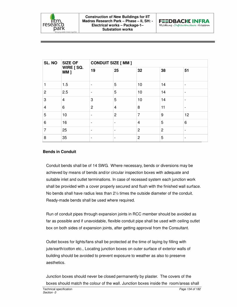
Construction of New Buildings for IIT Madras Research Park – Phase – II, SH: -
Electrical works – Package-1– Substation works
Technical specification Page 134 of 182 Section -3
CONDUIT SIZE [ MM ] SL. NO SIZE OF WIRE [ SQ. MM ] 19 25 32 38 51
1 1.5 - 5 10 14 -
2 2.5 - 5 10 14 -
3 4 3 5 10 14 -
4 6 2 4 8 11 -
5 10 - 2 7 9 12
6 16 - - 4 5 6
7 25 - - 2 2 -
8 35 - - 2 5 -
Bends in Conduit
Conduit bends shall be of 14 SWG. Where necessary, bends or diversions may be
achieved by means of bends and/or circular inspection boxes with adequate and
suitable inlet and outlet terminations. In case of recessed system each junction work
shall be provided with a cover properly secured and flush with the finished wall surface.
No bends shall have radius less than 2½ times the outside diameter of the conduit.
Ready-made bends shall be used where required.
Run of conduit pipes through expansion joints in RCC member should be avoided as
far as possible and if unavoidable, flexible conduit pipe shall be used with ceiling outlet
box on both sides of expansion joints, after getting approval from the Consultant.
Outlet boxes for lights/fans shall be protected at the time of laying by filling with
jute/earth/cotton etc., Locating junction boxes on outer surface of exterior walls of
building should be avoided to prevent exposure to weather as also to preserve
aesthetics.
Junction boxes should never be closed permanently by plaster. The covers of the
boxes should match the colour of the wall. Junction boxes inside the room/areas shall

Construction of New Buildings for IIT Madras Research Park – Phase – II, SH: -
Electrical works – Package-1– Substation works
Technical specification Page 135 of 182 Section -3
be avoided. In case these are unavoidable they can be located in toilet/corridor/service
areas/stores etc., One bolt shall be welded to receive earth wire inside all switch
points.
All switch points shall be fixed at a level accessible from floor level. Conduits in wall
crossing area shall be sealed with M-Seal/epoxy compound after pulling the wires.
Switch Outlet and Junction Boxes
All concealed outlet boxes for switches, sockets and other receptacles shall be rust
proof and shall be of thick Galvanized steel (GI) boxes having smooth external and
internal surfaces.
All outlet boxes for receiving plug sockets and switches shall be of standard factory
make and of approved size, and shape. All boxes shall have adequate number of
knock out holes of required diameter and earthing terminal screws. Outlet boxes shall
have a minimum depth of 65 mm.
Light Outlet Boxes
The Light Outlet Boxes for concealed installation shall be round in shape and shall be
made of MS knock out holes/projections to connect MS pipes. Light outlet boxes for
surface installation shall be of MS (painted).
Inspection Boxes
Rust proof inspection boxes of 2 mm thick mild steel having smooth external and
Internal finish shall be provided to facilitate removal and replacement of wires, where
required.
Fan Outlet
For fixing of ceiling fans, circular outlet boxes made of 16 SWG steel sheet, 100 mm
diameter, complete with fan hook fabricated art of 12 mm dia mild steel rod .
Construction of New Buildings for IIT Madras Research Park – Phase – II, SH: -
Electrical works – Package-1– Substation works
Technical specification Page 136 of 182 Section -3
Switches, Receptacles and Fixtures
Switches:
All 5/15 amps switches shall be enclosed type flush mounted for 240 volts AC. The
box in which the switches are fixed shall have an adjustable plate cover. Ample space
at the back and sides shall be provided for accommodating wires. Switch, controlling
the light point shall be connected to the phase wire of the circuit. The Switch plate
shall be white plastic or any other approved type and it should match the interior
design.
Wall Socket Outlets:
Following types of socket outlet shall generally be used for interiors:
All sockets shall be of shutter type.
5A 3 Pin Switched Socket outlet in guest rooms, Toilet, office area, lobby, restaurant
etc.,
5A 3 Pin unswitched socket outlet for TV supply with Independent 5A SP Control
switch near the bedside.
15/5A 3 pin switched socket with Indicator for power points.
15A, 5 pin domestic plug point for using mixie, microwave oven etc., should be
provided.
Guest rooms kitchen, main kitchen and split AC units, etc., shall only be operated by
metal clad industrial type socket and plug with suitable rating of MCBs of any one of
the following combinations as per design and rating of the equipment’s used. In pantry
area, where the domestic appliances are used, flush type switches and sockets can be
fixed.
16 Amps SP Industrial type socket controlled by 16 Amps SP MCB mounted on a
fabricated MS box with cover plate.
20 Amps SP Industrial type socket controlled by 20 Amps SP MCB mounted on a
fabricated MS box with cover plate.
Construction of New Buildings for IIT Madras Research Park – Phase – II, SH: -
Electrical works – Package-1– Substation works
Technical specification Page 137 of 182 Section -3
32 Amps S.P/T.P 230V/415V, Industrial type socket controlled by 32 Amps S.P/T.P.
MCB mounted in a fabricated MS box with cover plate.
No electrical cable/temporary cabling shall be allowed at floor level for connecting any
equipments on any account.
Installation of Conduits
Concealed Conduit System
Unless otherwise specified all wiring shall be in heavy gauge rigid MS conduit
embedded in wall, or ceiling and concealed in the false ceiling. The size of the conduit
shall be selected in conformity with relevant IS code and as specified in the table
6.8.3.b.6 given above. Factory made conduit bends and accessories shall be used.
Conduit shall be jointed using solvent cement as recommended by the conduit supplier.
The conduit in ceiling slab shall be straight as far as possible. Before the conduits are
laid in the ceiling, the position of the outlet points, controls, junction boxes shall be set
out clearly as per the dimensions and to minimize off-sets and bends. Conduits in
ceiling shall be bonded to the reinforcement rods with GI bonding wire to secure them
in position. MS light outlet/pull boxes shall be provided as required. The conduit in
ceiling slab shall be laid above the first layer of reinforcement rods to avoid cracks in
the ceiling surface.
Conduits concealed in the wall shall be secured rigidly by means of steel hooks/staples
at minimum 750 mm intervals. Before conduit is concealed in the walls, all chases,
grooves shall be neatly made to proper required dimensions to accommodate number
of conduits.
The chased portion of the walls for electrical works shall be plastered by electrical
Contractor to bring it to the finished wall surface. The outlet boxes, control switches,
and inspection and draw boxes shall be fixed as and when conduits are being fixed.
The recessing of conduits in walls shall be so arranged as to allow at least 12 mm
plaster

Construction of New Buildings for IIT Madras Research Park – Phase – II, SH: -
Electrical works – Package-1– Substation works
Technical specification Page 138 of 182 Section -3
cover on the same. Where conduit passes through expansion joints in the building,
adequate expansion fitting or other approved devices shall be used to take care of the
relative movement of expansion joints.
All grooves, chases etc., shall be refilled with cement mortar and finished up to wall
surface before plastering of walls is taken up by the general civil Contractor. Whenever
the conduits terminate into Control Boxes, distribution boards etc., conduits shall be
rigidly connected to the boxes/boards with check nuts on either side of the entry to
ensure electrical continuity. All opening of conduits, junction boxes shall be properly
plugged with MS stoppers or any other suitable materials, so that water, mortar, vermin
or any other foreign materials do not enter into the conduit system. All conduit ends
terminating into an outlet shall be provided with bushes of MS or rubber after the
conduit ends are properly filed to remove burrs and sharp edges. Necessary GI pull
wires shall be inserted into the conduit for drawing wires. The Insulated Earth wires
shall be run in each conduit originating from the panel board up to the Light, Socket
and Switch boxes. If the Electrical Contractor forgets to install any conduit/boxes etc.,
before the plastering/painting work is done by other agencies, he may be permitted to
install the same with prior permission of Owner/PMC/Consultant and the expenses
towards redoing the wall, floor, ceiling etc., shall be borne by the Electrical Contractor.
Open/Surface Conduit System
Conduits on surface of walls/RCC slabs shall be avoided as far possible. In case it is
not avoidable, prior approval in writing shall be obtained from Employer/Consultant on
the exact route. Heavy gauge GI saddles shall fix conduit. Distance between two
consecutive saddles shall not exceed 900 mm. No wooden gutties for fixing
saddles/clamps shall be used. Use of Rawl plug/steel fastener with hard
setting/scaling compound is recommended. Conduits shall be run in square and by
metrical lines. Wherever couplers, bends, or similar fittings are used, saddles shall be
provided at either side at a distance of 300 mm from the center of such fittings.
Conduits shall be joined by means of screwed couplers and screwed accessories only.
In long distance straight runs of conduit, inspection type couplers/junction boxes shall
be provided.
Construction of New Buildings for IIT Madras Research Park – Phase – II, SH: -
Electrical works – Package-1– Substation works
Technical specification Page 139 of 182 Section -3
Threading shall be long enough to accommodate pipe to the full threaded portion of the
Couplers and accessories. Cut ends of conduits shall have neither sharp edges nor
any burrs left, to avoid damage to insulation’s of wires.
Using pipe-bending machine shall do bends in conduit runs. Sharp bends shall be
accomplished by introducing solid bends, inspection bends or cast iron/ MS inspection
boxes. Radius of solid bends shall not be less than 75mm. Not more than 90-degree
bend shall be used in a conduit run from outlet to outlet.
All conduits opening shall be properly plugged with MS stoppers/bushes. Conduits
shall be adequately protected against rust by applying two coats of approved synthetic
enamel paint after the installation is completed and should be certified by the Site
Engineer. The certificate shall be submitted along with bills for payment.
Wherever conduits terminate into control boxes, outlet boxes, distribution boards etc., it
shall be rigidly connected to the box with check nuts on either side of the entry.
In ground floor, conduiting below the flooring should be avoided. Wherever it is
unavoidable, GI pipe should be used with prior approval of Employer/Consultant.
The entire conduit system shall be bonded to the earth.
Wiring
All wires shall have been manufactured in accordance with the latest IS Specification
(IS
694 - Part II).
All wires shall be FRLS insulated, copper conductors of 650-volt grade. Cross section
of the conductor shall be as per the specification mentioned in schedule of quantities.
Minimum cross section of conductor for electrical wiring shall be 1.5 mm square.
For single phase wiring, the colour of the insulation of phase conductors shall be
Red/Yellow/Blue and black for neutral. The colour coding adopted should be uniform
for the entire Project.

Construction of New Buildings for IIT Madras Research Park – Phase – II, SH: -
Electrical works – Package-1– Substation works
Technical specification Page 140 of 182 Section -3
Earthing is to be done by Green FRLS insulated copper conductor. For three phase the
insulation of phase conductors shall be Red/Yellow/Blue, as per relevant phase and
Black for neutral.
Earth wire shall always be of copper conductor FRLS insulated and colour of insulation
shall be Green.
Whenever wires are being terminated in a Distribution Board/Switch Box/Plug
point/Outlet Box etc., a minimum of 200 mm long extra wire should be provided in the
form of a loop for further maintenance use.
For each lot of wires, the Contractor shall submit all relevant test certificates issued by
the Manufacturer stating its origin, date of manufacture, constitution and standards to
which it complies. All wires and cables shall bear the manufacturer’s label and shall be
brought to site in original packing.
Only Authorized/certified wiremen and cable jointers shall be employed to do the cable
jointing work.
Wires shall not be jointed inside the conduit or pull boxes. Where unavoidable, joints
shall be made through approved mechanical connectors with prior permission of
Employer/Consultant.
Control switches shall be connected in the phase conductors only; and shall be ‘ON’
when knob is down. Switches shall be fixed in galvanized steel boxes. Plated screws
shall be used.
Power wiring shall be distinctly separate from lighting wiring.
Each circuit phase wire from the distribution boards should be followed with a separate
neutral wire of the same size as that of the circuit wire.
Wires originating from two different phases shall not run in the same conduit.

Construction of New Buildings for IIT Madras Research Park – Phase – II, SH: -
Electrical works – Package-1– Substation works
Technical specification Page 141 of 182 Section -3
Drawing Conductors
The drawing and jointing of MS insulated copper/aluminium conductor wire and cables
shall be executed with due regard to the following precautions. While drawing wires
through conduits, care shall be taken to avoid scratches, etc., Care shall also be taken
to ensure that the insulation is not peeled off either in portions or as a whole; and the
conductor is not broken anywhere. There shall be no sharp bends that may lead to
the breakage of the conductor.
FRLS Insulated copper conductor wire ends shall be soldered (at least 20 mm length)
before inserting into the switch for termination and Conductors having nominal cross
sectional areas exceeding 10 Sq.mm shall always be provided with cable sockets/lug
of same material as that of conductor.
Strands of wires shall not be cut for connecting terminals. The terminals shall have
sufficient cross sectional area to take all strands and shall be soldered. Connecting
brass screws shall have flat ends. All looped joints shall be soldered and connected
through block/connectors. The pressure applied to tighten terminal screws shall be just
adequate, neither too much nor too less.
At all bolted terminals, brass flat washer of large area and approved steel spring shall
be used. Brass nuts and bolts shall be used for all connections. For all internal wiring,
FRLS insulated wires of 650/1100 volts grade shall be used.
The sub-circuit wiring for point shall be carried out in loop system and no joints shall be
allowed in the length of the conductors. If the use of joint connections are unavoidable
due to any specific reason, prior permission, in writing, shall be obtained from the
Employer/Consultant. No wire shall be drawn into any conduit, until all work of any
nature, that may cause injury to wire, is completed. Care shall be taken in pulling the
wires so that no damage occurs to the insulation of wire. Before the wires are drawn
into the conduits, the conduits shall be thoroughly cleaned of moisture, dust, dirt or any
other construction debris, by forcing compressed air through the conduits. All sub-
circuit wiring for light points shall be with 2.5 Sq.mm FRLS insulated copper conductor.

Construction of New Buildings for IIT Madras Research Park – Phase – II, SH: -
Electrical works – Package-1– Substation works
Technical specification Page 142 of 182 Section -3
Mains and Sub-Mains
Mains and sub-mains cable or wires where called for shall be of the rated capacity and
approved make. Every main and sub-main wire shall be drawn into an independent
adequate size conduit.
An independent earth wire of the proper rating shall be provided for each sub main, two
earth wires of proper rating shall be provided for every single phase sub main. For every
3-phase sub main, two earth wires of proper rating shall be provided along with the sub
main.
The earth wires shall be fixed to conduits by means of clips at not less than 1000 mm
distance. For mains and sub-mains extra lengths of cable shall be provided to facilitate
easy connections and maintenance.
Load Balancing
Balancing of circuits in three phase installation shall be planned before the
commencement of wiring and shall be strictly adhered to.
Colour Code of Connectors
Colour code shall be maintained for the entire wiring installation as red, yellow, blue for
three phases, black for neutral.
Measurements
Point Wiring
All outlets connected on a lighting circuit shall be measured under point wiring. It shall
include wiring from first switch point of the circuit up to light, fan, socket outlet via
switches, regulators, controls etc., as called for. Generally, the following accessories
shall be included.
Light outlet box with ceiling rose
Lamp holder
Construction of New Buildings for IIT Madras Research Park – Phase – II, SH: -
Electrical works – Package-1– Substation works
Technical specification Page 143 of 182 Section -3
Switches
5/15 A socket outlets with plug tops
M.S./G.I. outlet box
Fan hook
Fan regulator
Small wiring from outlet to Fan/Light
Conduit and accessories
Circuit main for light circuit
Circuit main is inclusive in the point wiring and however wherever called for separately
in the BOQ alone shall be measured in length from the Distribution Board/Panel Board
up to the first switch box on that circuit only; from this point onwards , all looping will
be measured under point wiring.
General
Point wiring and circuit wiring should be done in independent conduits and should not
be taken through one conduit.
Fan regulator box, fans, light fittings, calling bells are to be properly earthed. In respect
of 5 Amps conventional plug point, the third pin should be earthed with 2.5 Sq.mm
green FRLS insulated copper wire.
All flush type switches and accessories will be used with 3-mm thick hylam sheet in MS
box. For the purpose of determining the load per circuit. The following electric rating of
points shall be assumed.
Light point : 60 watts or as specified
Conventional plug point : 100 watts
(Plug point in light switch box or independent)
Fan points : 80 watts
Exhaust fan points : 60 watts or as specified
Construction of New Buildings for IIT Madras Research Park – Phase – II, SH: -
Electrical works – Package-1– Substation works
Technical specification Page 144 of 182 Section -3
Lights, fans and 5 A points shall be wired on a common circuit. Each circuit shall not
have more than a total of ten points of lights, fans and 5 A socket outlets or a load of
800 watts whichever is less. The ceiling fan point shall be complete with special outlet
box including fixing and connection of regulator. Supply and fixing of 5A switch for each
ceiling fan is included in scope of Contractor.
For 15A Power Plug Points
In one circuit, there shall not be more than two 15A power plug points and 2 x 4 Sq.mm
copper conductor wires shall connect circuit.
One flush type plug socket outlet and switch shall be fixed for each power point on 3
mm thick hylem sheet cover. Plug socket can be standard type or 15/5 A universal type
The circuit main would commence from DB and end up to the switch box. Looping of
circuit would be done to second 15A power point from first 15A power point and shall
be counted as power point wiring.
Each circuit would have its own 2.5 Sq.mm green FRLS insulated copper wire from DB
to switch box and would be connected to third pin of socket outlet.
Electrical load for each 15A power point would be considered as 1000 watts.
Group Wiring
The following specification is applicable only when three or more lights (or) more than
500 watts of lighting load are controlled by one MCB.
Lights would be controlled by rated capacity MCB and connected by wire size, as
specified in schedule of quantities. However, it shall not be less than 5 A and 2.5
sqmm respectively. Light points controlled by one MCB would be in parallel.
MCB for these lights should be installed in a suitable MS box with hylam sheet cover.
Total electric load is to be controlled from this. “Group lighting board” would not exceed
3000 watts or six groups of lights or as specified in the approved drawings. Circuits
with earthing for this Group Lighting Board would always be from DB of size as
specified in schedule of quantities.

Construction of New Buildings for IIT Madras Research Park – Phase – II, SH: -
Electrical works – Package-1– Substation works
Technical specification Page 145 of 182 Section -3
“Group lights” points would commence from DB including circuits, surface/concealed
conduit system, necessary wiring, MS switch box, M.C.B, hylam sheet cover and outlet
box up to last light of the group.
8.0 TECHNICAL SPECIFICATION FOR LIGHT FITTINGS AND ACCESSORIES
This specification covers design, installation and testing of light fittings and accessories
conforming to relevant IS standards and specifications.
Standards:
The lighting and their associated accessories such as lamps, reflectors, housings,
ballasts, etc., shall comply with the latest applicable standards, more specifically the
following:
5. Electric Light Fittings : General and Safety requirements IS - 1913.
6. Industrial Light Fittings with metal reflectors IS - 1777
7. Decorative lighting outposts - IS - 5077
8. Flood lights - IS - 1947
9. Luminaries for street lights - IS - 2149
10. Bayonet lamp holders - IS - 1258
11. Bi-pin lamp holders for tubular-fluorescent lamps -IS - 3323
12. Ballast’s for use in fluorescent light fittings IS - 1534
13. Starters for fluorescent lamps IS - 2215
14. Ballast for HP MV lamps-IS - 6616
15. Capacitors for use in fluorescent, HPMV / sodium Vapour lamps circuits. IS-
2215
16. Tubular Fluorescent lamps-IS - 2418 (Part I)
17. High pressure mercury vapour lamps - IS - 2183
18. Tungsten filament general electric lamps-IS - 418
Construction of New Buildings for IIT Madras Research Park – Phase – II, SH: -
Electrical works – Package-1– Substation works
Technical specification Page 146 of 182 Section -3
19. Water proof electric Light Fittings: IS 3524.
20. Water tight electric Light Fittings: IS 3553.
21. LED fittings: IS 16101 to106 & 16108 of 2012
22.22.22.22. LED driver: 15885 of 2012.
Light Fittings - General Requirements
All the light fixtures should be energy efficient.
Fittings shall be designed for continuous trouble free operation under any atmospheric
conditions without reduction in lamp life or without deterioration of materials and internal
wiring. Outdoor fittings shall be weather and rain proof.
Fittings shall be so designed as to facilitate easy maintenance including cleaning,
replacement of lamps/ starters etc.
All fittings shall be supplied complete with lamps. All mercury vapour and sodium vapour
lamp fittings shall be complete with accessories like ballast’s, power factor improvement
capacitors, starter, etc. Outdoor type fittings shall be provided with weatherproof boxes.
Fluorescent lamp fittings shall be complete with all accessories like ballast’s, power
factor improvement capacitors, and starters capacitors for correction of stroboscopic
effect.
Each fitting shall have a terminal block suitable for loop-out connection by 1100V PVC
insulated copper conductor wires up to 4 Sq.mm. The internal wiring should be
completed by the manufacturer by means of standard copper wire and terminated on the
terminal block.
All hard wares used in the fitting shall be suitably plated or anodized and passivated for
use in industrial atmosphere.
Construction of New Buildings for IIT Madras Research Park – Phase – II, SH: -
Electrical works – Package-1– Substation works
Technical specification Page 147 of 182 Section -3
For Earthing, each light fitting shall be provided with an earthing terminal. All metal or
metal enclosed parts of housing shall be bonded and connected to the earthing terminal
so as to ensure satisfactory earthing continuity throughout the fixture.
Energy Efficiency:
Fluorescent lamps are reasonably efficient at converting input power to light.
Nevertheless, much of the power supplied into a fluorescent lamp – ballast system
produces waste heat energy.
16. There are three primary means of to improving the efficiency of a fluorescent
lamp-ballast system:
(ββ) Reduce the ballast losses.
(χχ) Operate the lamp(s) at a high frequency.
(δδ) Reduce losses attributable to the lamp electrodes.
Newer, more energy-efficient ballasts, both magnetic and electronic, exploit one or more
of these techniques to improve lamp-ballast system efficacy, measured in lumens per
watt. The losses in magnetic ballasts have been reduced by substituting copper
conductors for aluminum and by using higher-grade magnetic components. Ballast
losses may also be reduced by using single ballast to drive three or four lamps, instead
of only one or two. Careful circuit design increases efficiency of electronic ballast’s. In
addition, electronic ballasts which convert the 60Hz supply frequency to high frequency,
operate fluorescent lamps more efficiently than is possible at 60 Hz. Finally, in rapid start
circuits, some magnetic ballasts improve efficacy by removing power to the lamp
electrodes after starting.
Ballasts:
The ballast’s shall be designed for long life and low power loss. They shall be mounted
using self-locking, anti-vibration fixtures and shall be easy to remove without demounting
the fittings. The enclosures shall be dust tight and non-combustible.
Construction of New Buildings for IIT Madras Research Park – Phase – II, SH: -
Electrical works – Package-1– Substation works
Technical specification Page 148 of 182 Section -3
Ballast’s shall be electronic type, inductive, heavy-duty type, filled with thermosetting,
insulating, moisture repellent polyester compound filled under pressure or vacuum.
Ballasts shall be provided with taps to set the voltage. The ballast wiring shall be of
copper and they shall be free from dust.
High Frequency ballast:
High Frequency ballast shall be of electronic type with high voltage with stand capacity.
Ballast shall be provided with re-fuseable type. The harmonics level of the electronic
ballast shall be with in 10% THD.
Ballast Factor :
One of the most important ballast parameters for the lighting designer/engineer is the
ballast factor. The ballast factor is needed to determine the light output for a particular
lamp-ballast system. Ballast factor is a measure of the actual lumen output for a specific
lamp-ballast system relative to the rated lumen output measured with reference ballast
under ANSI test conditions (open air at 25 degrees C [77 degrees F]).
Ballast factor is not a measure of energy efficiency. Although a lower ballast factor
reduces lamp lumen output, it also consumes proportionally less input power. As such,
careful selection of a lamp-ballast system with a specific ballast factor allows designers
to better minimize energy use by “tuning” the lighting levels in the space. For example, in
new construction, high ballast factors are generally best, since fewer luminaries will be
required to need the light level requirements. In retrofit applications or in areas with less
critical visual tasks, such as aisles and hallways, lower ballast factor ballast’s may be
more appropriate.
To avoid a drastic reduction in lamp life low ballast factor ballast’s (<70%) should operate
lamps in rapid start mode only.
Construction of New Buildings for IIT Madras Research Park – Phase – II, SH: -
Electrical works – Package-1– Substation works
Technical specification Page 149 of 182 Section -3
Harmonics:
When a current or voltage wave shape deviates from the ideal (sinusoidal), current or
voltage harmonics are produced. Harmonics are sinusoidal voltage or currents that are
higher multiples of the fundamental frequency. For example the harmonics of 60Hz, 120
Hz, 180Hz, etc., representing the first (fundamental), second, third, etc. multiples.
Fluorescent ballast’s affect the current, as opposed to the input voltage; in the process,
current harmonics are generated. The amplitude of these harmonics are expressed as a
percentage of fundamental.
Recently electrical utilities have been concerned with the growing use of electrical
equipment that generates harmonics. Such equipment may include variable speed
drives, uninterruptible power supplies, personal computers, and electronic ballasts, any
circuit that is nonlinear (e.g. a gas discharge lamp) uses rectifying circuits, or uses high
speed switching systems will generate harmonics. If any one or combination of the
above systems makes up a significant portion of building’s electrical load, the following
undesirable effects may result:
• Overloading of transformers
• Adding of current to the neutral in three phase electrical distribution systems
• Current/Voltage surges and/or spikes due to circuit resonance’s with one or more
of the harmonic frequencies
• Interference with electrical equipment or communications on the same circuit
• Distortion of the electrical service entrance voltage with accompanying adverse
effects on the performance of other electrical equipment in the building.
Harmonic Distortion and Electronic Ballasts:
The harmonic issue first surfaced as a concern to the professional lighting community
when a major utility announced that electronic ballasts were required to have total
harmonic distortion (THD) of less than 20% of the fundamental in order to qualify for their
rebate program. Electronic ballasts manufacturers responded to the utility’s requirement
by employing passive filtering that met the 20% limit at a slightly higher cost to the end
user.
Construction of New Buildings for IIT Madras Research Park – Phase – II, SH: -
Electrical works – Package-1– Substation works
Technical specification Page 150 of 182 Section -3
To help understand the issue, magnetic ballasts of interest to examine and compare the
harmonics generate it. The harmonics for some magnetic ballasts exceed the 20% limit,
and have been measured at levels over 37%. This suggests that there are presently
many magnetic ballasts in use that exceed the 20% THD limit. These ballasts have not
been known to cause any problems with electrical distribution where they are installed,
further suggesting that the choice of a 20% limit on THD may be arbitrarily conservative.
In any case, most electronic ballasts manufacturers now make electronic ballasts that
are well under the 20% limit.
Harmonic Distortion and power factor:
Utilities are concerned with low power factors because end users draw higher currents
for the power that they are using. Ideally, lighting equipments should have a power factor
greater than 0.9 and is possible. Power factors of less than 1.0 occur when the voltage
and current generated by electronic ballasts reduce power factor due to a distorted
current wave shape. (Harmonic currents produced by other types of electronic
equipment can also lower the power factor produced by producing a phase shift between
the voltage and current.)
Electronic ballast manufacturers now make a habit of publishing the percentage of total
harmonic distortion (THD) produced by their products. This allows lighting professional to
quantity how the installation of electronic ballasts in a building will affect power factor.
Electrical distribution wiring may be sized accordingly. The relationship between power
factor and total harmonic distortion with no voltage-current phase shift may be
determined as follows:
Power factor = � 1 /(1+THD2)
As long as there is no voltage –current phase shift contribution to the power factor, THD
may be as high as 48% and maintain a power factor of over 0.90.
Guideline Specifications:
The following ballasts specifications may be used as a guideline for full-size fluorescent
lamp ballasts. In general, for important applications, detailed specifications should be
Construction of New Buildings for IIT Madras Research Park – Phase – II, SH: -
Electrical works – Package-1– Substation works
Technical specification Page 151 of 182 Section -3
included for ballasts. The specification may include acceptable manufacturers and model
numbers, especially when using electronic ballasts.
Electronic Ballast’s:
1. UL listed Class P.
4. Sound Rated A
5. Total harmonic distortion 32%(< 20% for rebates) with input current third
harmonic not to exceed ANSI recommendation.
6. Ballast shall conform to ANSI specification C.82, 11-19XX
7. Power factor 0.90
8. Enclosure size and wiring in same color as magnetic ballast (retrofit
applications).
9. Ballast factor of _________ (see chart or manufacturer’s literature, or as
required).
10. Light regulation ± 10% with ± 10% input voltage Variation.
11. Lamp current crest factor �1.7.
12. Flicker 10% or less with any lamp suitable for the ballasts.
13. Lamps shall be operated in (instant start0 (rapid start)(rapid start, stepped
output)(rapid start, continuously adjustable output) mode.
14. Shall be designed to with stand line transients, per IEEE 587,category A.
15. Circuit diagrams and lamp-ballast connections shall be displayed on all
ballast packages.
Painting/Finish:
All surfaces of the fittings shall be thoroughly cleaned and degreased and the fittings
shall be free from scale, rust, sharp edges, and burrs. The housing shall be stove-
enameled or anodized as required. The surface shall be scratch resistant and shall show
no sign or cracking or flaking when bent through 90° over.
Decorative Type Fittings:
Decorative fluorescent fittings shall be provided with mounting/housing channel cum
reflectors or CRCA steel sheet, stove enameled diffusers or louvers shall be translucent
white prystyrene.
Construction of New Buildings for IIT Madras Research Park – Phase – II, SH: -
Electrical works – Package-1– Substation works
Technical specification Page 152 of 182 Section -3
Accessories for Light Fitting Reflectors:
The reflectors shall be made of CRCA steel sheet/aluminium/silvered glass/chromium
plated sheet copper as required. The thickness of reflectors shall be as per relevant
standards. Reflectors made of steel shall have stove enameled/vitreous enameled/
epoxy coating finish for the reflectors shall be as specified. The reflectors shall be free
from scratches blisters and shall a smooth and glossy surface with optimum light
reflecting coefficient. Reflectors shall be readily removable from the housing for cleaning
and maintenance without use of tools.
Lamp/Starter Holders:
Lamp holders shall have low contact resistance and shall be resistant to wear. They shall
hold lamps in position under normal conditions of shock and vibration prevalent in an
industrial atmosphere.
Lamp holders for fluorescent lamps shall be of spring loaded bi-pin rotor type. Live parts
of the lamp holder shall not be exposed during insertion or removal of the lamp or after
the lamp has been taken out.
Lamp holders for incandescent and mercury vapour lamps shall be bayonet type up to
100 W and Edison screw type for higher wattage. Starter holder for fluorescent lamps
shall be so designed that they are mechanically robust and shall be capable of
withstanding shocks during transit, installation and use.
Capacitors:
The Capacitors shall have a constant value of capacitance and shall be connected
across the supply of individual lamp circuits. The capacitor shall have a value of
capacitance so as to correct the power factor of its corresponding lamps circuit to 0.95
lag or better capacitor shall be hermetically sealed preferably in a metal enclosure to
prevent seepage of impregnate and ingress of moisture.
Construction of New Buildings for IIT Madras Research Park – Phase – II, SH: -
Electrical works – Package-1– Substation works
Technical specification Page 153 of 182 Section -3
Lamps:
Lamps shall be of PL/SL/incandescent as specified type in BOQ. Fluorescent lamps
shall be “day light colour” type unless otherwise specified and shall be provided features
to avoid blackening of lamp ends.
Mercury vapour lamps shall be of high pressure, colour corrected type.
Lamps shall be capable of withstanding vibrations prevalent in an industrial atmosphere
and connections at lend in wires and filament/electrodes shall not break under such
circumstances.
LED lamps:
When choosing LED lamps its optical properties must be considered Properties such as
lumens output, intensity distribution and source size need to be suited to the optical
system of application.
The selected type of fitting shall not produce any glare and the diffusers are designed
such that the lighting is distributed to have a pleasant lighting output. The luminous
intensity and the distribution of lighting shall suit the requirement of the area where the
lighting is planned.
LED Drivers:
The drive units for LED shall generate minimum harmonics and shall be of minimum
power loss. It is preferable to have the drivers mounted in the fitting itself.
Utilities are concerned with low power factors because end users draw higher currents
for the power that they are using. Ideally, lighting equipments should have a power factor
greater than 0.9 and is possible. Power factors of less than 1.0 occur when the voltage
and current generated by electronic ballasts reduce power factor due to a distorted
current wave shape. (Harmonic currents produced by other types of electronic
Construction of New Buildings for IIT Madras Research Park – Phase – II, SH: -
Electrical works – Package-1– Substation works
Technical specification Page 154 of 182 Section -3
equipment can also lower the power factor produced by producing a phase shift between
the voltage and current.)
Electronic ballast manufacturers now make a habit of publishing the percentage of total
harmonic distortion (THD) produced by their products. This allows lighting professional to
quantity how the installation of electronic ballasts in a building will affect power factor.
Electrical distribution wiring may be sized accordingly. The relationship between power
factor and total harmonic distortion with no voltage-current phase shift may be
determined as follows:
Power factor = � 1 /(1+THD2)
9.0 PVC CONDUITS IN RCC & BRICK WORK& CEILING SCOPE: Providing specified PVC conduit and laying / erecting in RCC work, such as slab, beam, column before casting as per approved Method of Construction along with of all required material including hardware, binding wire, fish wire; accessories such as deep / long neck PVC junction boxes, PVC / MS junction / draw-in boxes, check-nuts, flexible PVC pipe, drawing fish-wires and making all piping rigid, removing debris from site and supervising the work during casting to confirm rigidity, continuity and avoid damages. MATERIAL: All non-metallic conduit pipes and accessories shall be of suitable material complying with IS: 2509-1973 and IS:3419-1989 for rigid conduits and IS: 9537 (Part 5) 2000 for flexible conduits. The interior of the conduits shall be free from obstructions. PVC Conduit: PVC pipe of minimum 20mm dia and above depending on No. of wires to be drawn (refer Table) ISI mark, Heavy-duty grade (2mm thick), accessories for PVC pipes of the same make that of pipe; Couplers, long Bends, deep Junction boxes of required ways and resin / adhesive to make all joints rigid. Junction boxes / Draw-in boxes: Junction box shall be 5 sided with removable top plate and of suitable size to accommodate No. of entries; PVC or fabricated from 16g CRCA sheet steel with earth terminal duly treated with antirust treatment and painted with two coats of red oxide paint. There shall be knockout holes in required numbers and dia. for entry of conduit pipes and arrangement to fix cover plates on it. Hardware: ‘U’ nails, plumbing and general use nails of required sizes, washers, check-nuts, steel binding wire, steel fish wire etc.

Construction of New Buildings for IIT Madras Research Park – Phase – II, SH: -
Electrical works – Package-1– Substation works
Technical specification Page 155 of 182 Section -3
METHOD OF CONSTRUCTION: Concealing of PVC conduits: General: Work shall be done in co-ordination with civil work and to suite final approved layout. Size of conduit shall be correct depending on number of wires to be drawn. Separate pipe shall be used for each phase in single phase distribution and for power and light distribution and also for wiring for other utilities like data, telephone, TV cabling, etc. The distance between pipes shall not be less than 300 mm or anti electrostatic partition is to be provided. Adequate use of conduit accessories shall be made at required locations. Entries in wall shall be at level of corresponding conduit with colour coding for Visual identification Flexible conduits shall be used at expansion joints. Erection shall be done as per the layout finalized, with minimum sharp bends, with junction boxes at angular junctions and for straight runs at every 4.25m, in such manner so as to facilitate drawing of wires. All PVC conduit bending shall be done with Bending Spring. All joints shall be made rigid with resin. Concealing of PVC conduits in RCC work: Work shall be commenced after fixing of steel re-enforcement on centering material. Conduits shall be firmly fixed on steel of RCC work by binding wire. Fixing of conduits shall be such that it will remain rigid during casting of slab, beam, and column even after use of vibrator. Deep junction boxes and other draw-in boxes shall be such that their open end and centering material will not have gap in between so as to avoid concrete entering inside even after fixing covers to steel re-enforcement; and be filled with dry sand. Open ends of conduits; to be concealed in walls, shall be provided with couplers / sockets at ends and be flush with bottom of beam, and located at the center of the beam. As far as possible bunching / grouping of conduits shall be avoided so that it will not affect strength of RCC work especially in beams. Suitable steel fish wire shall be drawn through in the conduits for drawing of wires later on. Concealing of PVC Conduits in walls / flooring: Chases shall be made in walls of adequate width, with cutter and chiseling through it. Necessary finishing of the wall surface shall be done. Work in flooring shall not disturb RCC work, Conduits of adequate size shall be erected with use of appropriate accessories, and ‘U’ nails. All joints shall be made rigid with resin. Draw-in / inspection boxes shall be fixed with check-nut, flush with surrounding surface and earthed. ADDITIONAL REQUIREMENTS (i) Making chase (a) The chase in the wall shall be neatly made and of ample dimensions to permit the conduit to be fixed in the manner desired. (b) In the case of buildings under construction, the conduits shall be buried in the wall before plastering, and shall be finished neatly after erection of conduit. (c) In case of exposed brick / rubber masonry work, special care shall be taken to fix the conduit and accessories in position along with the building work. (ii) Fixing conduits in chase (a) The conduit pipe shall be fixed by means of staples, J-hooks, or by means of saddles, not more than 60 cm apart or by any other approved means of fixing. (b) All threaded joints of conduit pipes shall be treated with some approved preservative compound to secure protection against rust.
Construction of New Buildings for IIT Madras Research Park – Phase – II, SH: -
Electrical works – Package-1– Substation works
Technical specification Page 156 of 182 Section -3
(iii) Fixing conduits in RCC work (a) The conduit pipes shall be laid in position and fixed to the steel reinforcement bars by steel binding wires before the concreting is done. The conduit pipes shall be fixed firmly to the steel reinforcement bars to avoid their dislocation during pouring of cement concrete and subsequent tamping of the same. (b) Fixing of standard bends or elbows shall be avoided as far as practicable, and all curves shall be maintained by bending the conduit pipe itself with a long radius, which will permit easy drawing in of conductors. (c) Location of inspection / junction boxes in RCC work should be identified by suitable means to avoid unnecessary chipping of the RCC slab subsequently to locate these boxes. (iv) Fixing inspection boxes (a) Suitable inspection boxes to the minimum requirement shall be provided to permit inspection and to facilitate replacement of wires, if necessary. (b) These shall be mounted flush with the wall or ceiling concrete. Minimum 65mm depth junction boxes shall be used in roof slabs and the depth of the boxes in other places shall be as per IS: 2667-1988. (c) Suitable ventilating holes shall be provided in the inspection box covers. (v) Fixing switch boxes and accessories. Switch boxes shall be mounted flush with the wall. All outlets such as switches, socket outlets etc. shall be flush mounting type, unless otherwise specified in the Additional Specifications. (vi) Fish wire To facilitate subsequent drawing of wires in the conduit, GI fish wire of 1.6mm/1.2mm (16/18 SWG) shall be provided along with the laying of the recessed conduit and it shall be protrude both the conduit ends by 230mm (vii) Bunching of Cables (a) Cables carrying Direct Current may, if desired, be bunched whatever their polarity, but cables carrying alternating current, if installed in metal conduit shall always be bunched so that the outgoing and return cables are drawn into the same conduit. (b) Where the distribution is for single phase loads only, conductors for these phases shall be drawn in one conduit. (c) In case of three phase loads, separate conduits shall be run from the distribution boards to the load points, or outlets as the case may be. EARTHING REQUIREMENTS (i) A protective (earth) conductor shall be drawn inside the conduit in all distribution circuits to provide for earthing of non-current carrying metallic parts of the installation. These shall be terminated on the earth terminal in the switch boxes, and/or earth terminal blocks at the DB’s. (ii) Gas or water pipe shall not be used as protective conductors (earth medium).
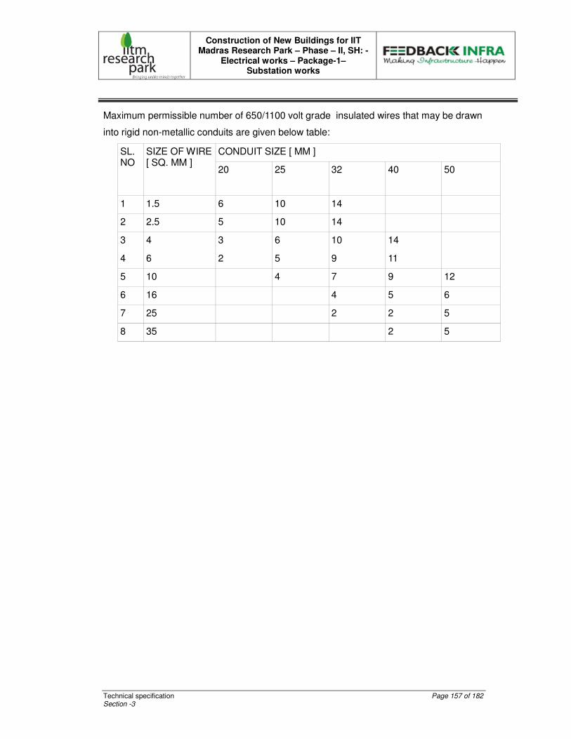
Construction of New Buildings for IIT Madras Research Park – Phase – II, SH: -
Electrical works – Package-1– Substation works
Technical specification Page 157 of 182 Section -3
Maximum permissible number of 650/1100 volt grade insulated wires that may be drawn
into rigid non-metallic conduits are given below table:
CONDUIT SIZE [ MM ] SL. NO
SIZE OF WIRE [ SQ. MM ]
20 25 32 40 50
1 1.5 6 10 14
2 2.5 5 10 14
3 4 3 6 10 14
4 6 2 5 9 11
5 10 4 7 9 12
6 16 4 5 6
7 25 2 2 5
8 35 2 5
Construction of New Buildings for IIT Madras Research Park – Phase – II, SH: -
Electrical works – Package-1– Substation works
Technical specification Page 158 of 182 Section -3
10.0 TECHNICAL SPECIFICATION FOR LIGHTNING ARRESTOR
SCOPE
The scope of work shall cover supply, Installation, Testing and Commissioning of
reputed make air, earth terminations and down conductors for the entire building as per
the relevant Indian standards and specifications given below.
STANDARDS
The following standards shall apply:
IS 2309 – 1969 : Code of practice for the protection of buildings and allied structures
against lighting.
IS 3043 – 1966 : Code of practice for earthing.
IS 5216 – 1969 : Safety procedures and practice in electrical work.
Indian Electricity Act 1910 and rules issued there under.
British Standard Code of Practice 326 – 1965.
AIR TERMINAL
CONSTRUCTION
The lightning arrestor should be made out of 100 mm dia (minimum) copper sphere
consists of 5 pronged air terminal pointed probes at top. It shall be fitted on
approximately 25 mm dia copper tube with not less than 2 mm wall thickness and
1200mm long shall be welded to suitable base plate of size 6” x 6” made out of G.I. with
fixing arrangement shall be grouted to wall / slab/ terrace. Roof conductors/down
conductor/25x3 mm Cu. Strips as specified in Schedule of quantities shall be fixed on the
highest point of the tallest building in the Project site. The number(s) of Lightning
Arrestor(s) and its/their location shall be shown in the drawing(s).
Construction of New Buildings for IIT Madras Research Park – Phase – II, SH: -
Electrical works – Package-1– Substation works
Technical specification Page 159 of 182 Section -3
OFF CONDUCTORS
These shall be carried out if required under the advice of consultant to interconnect the
various lightning arrestors of one building near the top to extend the zone of protection.
These shall be of GI strip of size 25x6 mm as specified in Schedule of quantities and
shall be fastened securely to the building surface by means of GI saddles maximum 1m
apart, with GI nails/screws and shall have minimum number of joints.
DOWN CONDUCTORS
These shall be used for connecting the lightning arrestors/roof conductors to each
electrode of earth pit. Structures with a base area of up to 90 Sq.mm. may, if height of
the lightning arrestor gives sufficient protection, be equipped with one down conductor
only. These shall be of 25x3 mm size Cu. Strip, with minimum joints and shall be
fastened securely to the building surface by means of GI saddles, maximum 1 m apart
with GI nails/screws. Each down conductor shall have its own independent earth pit.
GENERAL
The lightning protection system shall have as few joints as possible and they shall be
mechanically and electrically effective. In general, joints for strips shall be tinned,
soldered and at least double riveted. Bolted joints shall only be used on test points or on
bonds to existing metals. Each down conductor shall be provided with a testing joint in a
position convenient for testing and at the same time away from Guest areas.
All other metal objects such as water tanks, iron staircase/railings, water or gas pipes on
top of, inside or by the side of a building should be at least 2 m away from the lightning
roof conductor/down conductor system.
The Lightning Arrestor(s) should not be installed near any structure used for storage of
inflammable materials. There shall not be any spire, flagstaff or other point close by the
lightning arrestor, which can impair its efficiency or the efficiency of air terminals. No
outdoor radio aerials or overhead line poles shall be located within a distance of 15 m
from the lightning arrestor.
Earthing system used for lightning protection must be independent of the equipment /
distribution earthing system.
Construction of New Buildings for IIT Madras Research Park – Phase – II, SH: -
Electrical works – Package-1– Substation works
Technical specification Page 160 of 182 Section -3
EARTHING
EARTH TERMINATION
The earth terminals and earth leads shall be as specified for earth station and
earthing
leads under section ‘EARTHING’.
TESTING
The entire lightning conductor installation shall be tested in accordance with the Indian
Standard Code and the following ground resistance values shall be recorded.
• Earthing Terminal (each)
• Earthing system (as a whole)
MODE OF MEASUREMENT
Each point air termination shall be measured as one unit for payment and shall include:
� Elevation rod and Multiple point head
� Base plate and concrete block
� Terminal connection
� Bimetallic connection, if any
Strip conductors shall be measured per unit length.
Each earth terminations shall be measured as one unit for payment and shall include:
� Electrode, lead wire & fixing accessories
� Soil treatment
� Excavation and refilling
Construction of New Buildings for IIT Madras Research Park – Phase – II, SH: -
Electrical works – Package-1– Substation works
Technical specification Page 161 of 182 Section -3
� Masonry chamber and cast iron cover
� Watering pipe
Earthing lead shall be measured on the basis of unit length for payment and shall
Include:
� Earth lead, clamps and fixing accessories
� Excavation and corrosion treatment of the earth leads
at the earth termination.
� Terminal connection at air and earth termination.
11.0 TECHNICAL SPECIFICATION FOR EARTHING
General
All the non-current carrying metal parts of electrical installation shall be earthed as per IS:
3043. All equipments, metal conduits, rising main, cable armour, switch gear, distribution
boards, meters, cable glands and all other metal parts forming part of the work shall be
bonded together and connected by two separate and distinct conductors to earth
electrodes.
Earthing shall be in conformity with the provisions of Rules 32, 61, 62, 67 and 68 IER
1956.
Construction.
Construction of New Buildings for IIT Madras Research Park – Phase – II, SH: -
Electrical works – Package-1– Substation works
Technical specification Page 162 of 182 Section -3
Earthing Conductors:
All earthing conductors shall be of high conductivity copper/GI strips and shall be
protected against mechanical damage and corrosion. The connection of earth
electrodes shall be strong, secure and sound and shall be easily accessible.
The earth conductors shall be rigidly fixed to the walls, cable trenches, cable tunnel
conduits and cables by using suitable clamps.
Main earth bus shall be taken from the main medium voltage panel to the earth
electrodes. The number of electrodes required shall be arrived at taking into
consideration the anticipated fault on the medium voltage network.
Earthing conductors shall be run from the exposed metal surface of the equipment and
connected to a suitable point on the sub main or main earthing bus.
All Switch Boards, Distribution Boards, Disconnecting Switches and Isolators shall be
connected to the earth bus. Earthing conductors shall be terminated at the equipment
end using suitable lugs, bolts, washers and nuts.
All conduits, cable armouring etc., shall be connected to the earth all along their run by
earthing conductors of suitable cross sectional area. The electrical resistance of
earthing conductors shall be low enough to permit the passage of fault current necessary
to operate a fuse/protective device and Circuit Breaker and shall not exceed 2 ohms.
Precautions
Earthing system shall be mechanically robust and the joints shall be capable of retaining
low resistance always. Joints shall be tinned, soldered and/or double riveted. All the
joints shall be mechanically and electrically continuous and effective. Joints shall be
protected against corrosion. The following table gives an idea on selection of size of
earth conductors for electrical equipments such as Transformers, Motors, Generators,
Switch gears, Cable Glands, etc., Size of the Conductor :
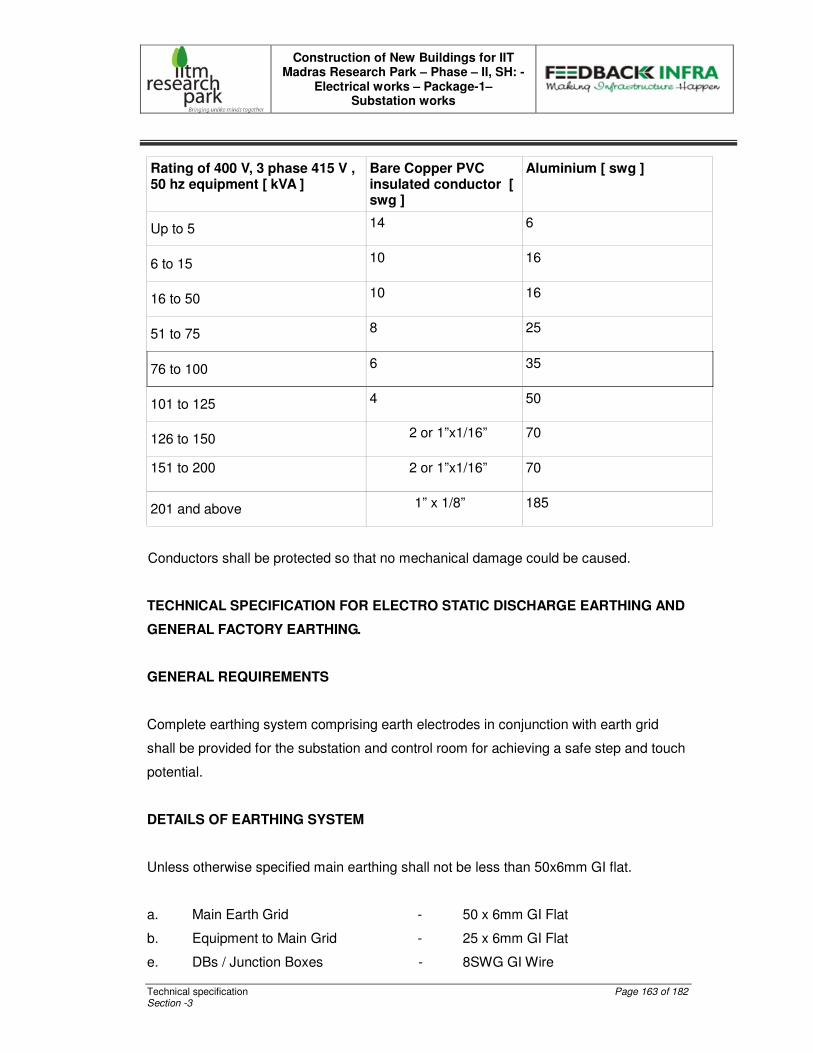
Construction of New Buildings for IIT Madras Research Park – Phase – II, SH: -
Electrical works – Package-1– Substation works
Technical specification Page 163 of 182 Section -3
Rating of 400 V, 3 phase 415 V , 50 hz equipment [ kVA ]
Bare Copper PVC insulated conductor [ swg ]
Aluminium [ swg ]
Up to 5 14 6
6 to 15 10 16
16 to 50 10 16
51 to 75 8 25
76 to 100 6 35
101 to 125 4 50
126 to 150 2 or 1”x1/16” 70
151 to 200
2 or 1”x1/16” 70
201 and above 1” x 1/8” 185
Conductors shall be protected so that no mechanical damage could be caused.
TECHNICAL SPECIFICATION FOR ELECTRO STATIC DISCHARGE EARTHING AND
GENERAL FACTORY EARTHING.
GENERAL REQUIREMENTS
Complete earthing system comprising earth electrodes in conjunction with earth grid
shall be provided for the substation and control room for achieving a safe step and touch
potential.
DETAILS OF EARTHING SYSTEM
Unless otherwise specified main earthing shall not be less than 50x6mm GI flat.
a. Main Earth Grid - 50 x 6mm GI Flat
b. Equipment to Main Grid - 25 x 6mm GI Flat
e. DBs / Junction Boxes - 8SWG GI Wire
Construction of New Buildings for IIT Madras Research Park – Phase – II, SH: -
Electrical works – Package-1– Substation works
Technical specification Page 164 of 182 Section -3
EQUIPMENT EARTHING
All electrical power items shall be earthed by two separate and distinct earth connections
from main earth bus.
Earthing pads shall be provided by the supplier of the apparatus/equipment at
accessible position. The connection between earthing pads and the earthing grid
shall be made by short and direct earthing lead free from kinks and splices. In case
earthing pads are not provided on the item to be earthed, same shall be provided in
consultation with Client.
Whether specifically shown in drawings or not, steel/RCC columns metallic stairs etc.
shall be connected to the nearby earthing grid conductors by two earthing leads.
Electrical continuity shall be ensured by bonding the different sections of hand-rails
and metallic stairs.
Metallic pipes, and cable tray sections for cable installation shall be bonded to ensure
electrical continuity and connected to earthing conductors at regular interval. Apart
from intermediate connections, beginning points shall also be connected to earthing
system.
Metallic conduits shall not be used as earth continuity conductor.
Wherever earthing conductor crosses or runs along metallic structures such as gas,
water, steam, conduits, pipes etc. and steel reinforcement in concrete, it shall be bonded
to the same.
Cable end boxes, glands, etc. shall be connected to the earthing conductor running
along with the supply cable which, in turn, shall be connected to earthing grid
conductor at minimum two points. The metallic screens of the single core cable, shall
be connected to earth at one end only.

Construction of New Buildings for IIT Madras Research Park – Phase – II, SH: -
Electrical works – Package-1– Substation works
Technical specification Page 165 of 182 Section -3
JOINTING
Earthing connections with equipment earthing pads shall be bolted type. Contact surface
shall be free from scale, paint enamel, grease, rust or dirt.
Two bolts shall be provided for making each connections . Bolted connections, after
being checked and tested shall be taped with PVC tape.
Resistance of the joint shall not be more than the resistance of the equivalent length of
the conductor.
GENERAL
The exact location of Earth Bus/conductor, earth electrodes and earthing points on the
equipment shall be determined at site in consultation with the Contractor.
Any change of methods, routing, size of conductor shall be subject to approval by the
Client.
EQUIPMENT EARTHING
Steel fences around the switch yard or station shall be connected to the earthing system
outside the fence at every second fence pole and at all corners and gate posts. Gates
shall be connected to the ground gate post with a flexible copper braid of equivalent size.
Piping
All piping shall be earthed at all service points in an approved manner. The relevant IS
rules are to be observed.
Circuit Breakers
All circuit breakers shall be earthed by two connections at diagonal corners of the
breaker racks. These connections must be from separate points of the earthing grid.
Construction of New Buildings for IIT Madras Research Park – Phase – II, SH: -
Electrical works – Package-1– Substation works
Technical specification Page 166 of 182 Section -3
Isolating Switches
The housing of all isolator and earthing switch operating mechanism shall be earthed at
points as near to the operating handle as possible.
Earthing strips shall connect the base of each switch from two separate points of the
earthing grid. Each earthing blade shall be connected to the earthing cable with flexible
braid.
DRAWINGS
Drawings to be submitted after award of contract with sufficient information to show the
earthing system which shall be furnished and the method of connection.
A profile drawing shall be included to indicate earthing of structure – mounted equipment.
INSPECTION AND TESTS
The following inspections and tests shall be carried out:
-Check to ensure that the earthing system components meet the specified dimensions;
-After completion of each earthing system, tests shall be carried out by the Contractor to
prove that the resistance of the earthing system and the voltage gradients inside and
outside the substation(s) are kept within safe limits. Results will be recorded and
submitted in tabular form etc.
Construction of New Buildings for IIT Madras Research Park – Phase – II, SH: -
Electrical works – Package-1– Substation works
Technical specification Page 167 of 182 Section -3
12.0 TECHNICAL SPECIFICATION FOR INSTALLATION
STANDARDS
The electrical installation work covered by this specification shall unless otherwise stated
comply with the requirements of the latest edition of relevant Indian Standard, statutory
regulations and codes of practices.
30. Indian Electricity Rules –1956
31. Tariff advisory committee - Approvals.
32. IS – 10118 :Code of practice for selection, installation & maintenance
of Switch gear and control gear
33. IS – 6600 : Guide for loading of oil immersed transformers.
34. IS – 3043 : Code of practice for earthing
35. IS – 2309 :Code of practice for protection of building and allied
structures against lightning
36. IS – 2274 : Code of practice for electrical wiring installation.
37. IS – 6665 : Code of practice for industrial lightning.
GENERAL REQUIREMENTS
The installation shall be carried out by an electrical contractor holding a valid license as
required by the respective State Government. The contractor shall provide particulars of
the license with valid date held by him or his subcontractor to the purchaser.

Construction of New Buildings for IIT Madras Research Park – Phase – II, SH: -
Electrical works – Package-1– Substation works
Technical specification Page 168 of 182 Section -3
13.0 TECHNICAL SPECIFICATION FOR TESTING AND COMMISSIONING
GENERAL
The testing and commissioning for all electrical equipment at site shall be according to
the procedure laid down below.
All electrical equipment shall be installed, tested and commissioned in accordance with
the latest relevant standards and codes of practices published by Indian standards,
institution wherever applicable and stipulations made in relevant general specifications.
The testing of all electrical equipment as well as the system as a whole shall be carried
out to ensure that the equipment and its components are in satisfactory condition and will
successfully perform its functional operation. The inspection of the equipment shall be
carried out to ensure that all materials, workmanship and installation conform to the
accepted design, engineering and construction standards, as well as accepted codes of
practice and stipulations made in the relevant general specifications.
The contractor using his own instruments, testing equipment as well as qualified testing
personnel shall carry out all tests.
The results of all tests shall be conform to the specification requirements as well as any
specific performance data guaranteed during finalization of the contract.
At the completion of the work, the entire installation shall be subject to the following tests
in presence of Employer/Consultant.
• Wiring Continuity Test
• Insulation Resistance Test
• Earth Continuity Test
• Earth Resistivity Test
Construction of New Buildings for IIT Madras Research Park – Phase – II, SH: -
Electrical works – Package-1– Substation works
Technical specification Page 169 of 182 Section -3
PREPARATION OF THE ELECTRICAL SYSTEM FOR COMMISSIONING
After completion of the installation at site and for the preparation of Electrical system
commissioning, the contractor shall carry out check and testing of all equipment and
installation in accordance with the agreed standards, codes of practice of Indian
Standards Institution and specific instructions furnished by the particular equipment
suppliers.
Checking required to be made on all equipment and installations at site shall comprise,
but not be limited, to the following:
The following checks shall be made on all equipment and installation at site:
Physical inspection for removal of any foreign bodies, external defects, such as
damaged insulators, loose connecting bolts, loose foundation bolts etc.
Check for grease, insulating/lubricating oil leakage and its proper quantity.
Check for the free movement of mechanism for the circuit breakers, rotating part of the
rotating machines and devices.
Check for tightness of all - cable, bus bars at termination/joints ends as well as earth
connections in the main earthing network.
Check for Clearance of live bus bars and connectors from the metal enclosure.
Check the proper alignment of all draw out device like draw out type circuit breakers.
Continuity checks in case of power cables.
Checking of all mechanical and electrical interlocks including tripping of breakers using
manual operation of relay.
Checking of alarm and annunciation circuits by manual actuation of relevant relays.
Check and calibrate devices requiring field adjustment/ calibration like adjustment of
relay settings etc.,
Check proper connection to earth network of all non-current carrying parts of the
equipment and installation.
Construction of New Buildings for IIT Madras Research Park – Phase – II, SH: -
Electrical works – Package-1– Substation works
Technical specification Page 170 of 182 Section -3
Test reports for all meters are to be furnished.
These tests shall be carried out on the equipment shall include but not be limited to the
above.
CABLES
Insulation resistance test with 1,000V megger for cables rated up to 1.1KV grade.
All cables of 1.1KV shall be subjected to high voltage test after joining and terminating
but before commissioning as per relevant standards.
In each test, the metallic sheath/screen/Armour should be connected to earth.
Continuity of all the cores, correctness of all connections as per wiring diagram,
correctness of polarity and phase of power cables and proper earth connection of cable
glands, cable boxes, Armour and metallic sheath, shall be checked.
EARTHING SYSTEM
Tests to ensure continuity of all earth connections. Tests to obtain earth resistance of the
complete network by using earth tester. The test values obtained shall be within the
limits.
All documents / records regarding test data, and other measured values of important
parameters finalized after site adjustment shall be handed over to the Owner in the form
of test reports for their future use and reference.
GENERAL
The scope of work for testing and commissioning of the total installation shall be for the
capital equipment’s like switchgears, cables, etc., and also for the associated equipment
like relays Cts, Pts cable etc.,
The scope of work for testing and commissioning of electrical equipment for the above
shall include but not limited to the following.
Construction of New Buildings for IIT Madras Research Park – Phase – II, SH: -
Electrical works – Package-1– Substation works
Technical specification Page 171 of 182 Section -3
3. Providing sufficient number of experienced Engineers, supervisors, Electricians
and wire men so that the installation can be commissioned in stipulated time.
4. All necessary instruments, tools, and tackles required for carrying out the testing
shall be provided by the bidder for commissioning.
5. The testing of electrical equipments shall be carried but as per the relevant Indian
standards/codes practices/Manufacturers instructions.
6. Cleaning of Electrical equipment, contacts, cleaning and greasing etc., all the
equipments and materials required for above shall be supplied by the bidder.
7. Correcting the panel/equipment wiring for proper functioning for the schemes
required.
8. Installation and wiring of additional equipment on panels like auxiliary contactors,
timers, etc., which may be additionally required for proper functioning of the
schemes.
9. Checking of equipment earthing and system earthing as a whole.
10. Testing of all the cables.
11. Co-ordination with other contractors for testing and commissioning of interface
cables.
All tests shall be performed in the presence of the bidder and customer/consultant. For
all types of visual inspections, checkings, precommissioning, commissioning test and
acceptance tests, relevant IS for the tests given therein shall be followed in addition to
the instructions in this technical specification the intention of giving the few test
procedures, described below, is to provide a guideline for the bidder. However bidder
shall not restrict themselves in carrying out only the tests described in this document.
The following Points are to be noted
a) Bidder shall submit their proposed test procedures for approval and shall not
commence testing without such approval is given.
b) Bidder shall check and test all electrical equipment and system installed and supplied
them, including equipment supplied by the owner.
Construction of New Buildings for IIT Madras Research Park – Phase – II, SH: -
Electrical works – Package-1– Substation works
Technical specification Page 172 of 182 Section -3
c) Bidder shall ensure that no tests are applied which may stress equipment above the
limits for field-testing recommended by the manufacturer. Bidder shall be responsible for
any damage to personnel or equipment resulting from improper test procedure including
the equipments supplied by Client.
d) All defective materials furnished by the bidder and defects due to poor workmanship
revealed through field testing, shall be corrected at bidder's expense without affecting the
completion of the project.
e) Bidder shall visually inspect all equipment for defects immediately results upon arrival
at site including those supplied by CLIENT.
f) CLIENT reserves the right to interpret and approve all test results prior to energisation
of circuits or apparatus.
SPECIAL NOTE: THE TENDERERS SHALL NOTE THAT ALL THE RATES QUOTED
BY THEM ARE INCLUDING THE TESTING CHARGES FOR DOING THE ABOVE
TESTS. CLIENT SHALL NOT REIMBURSE SEPARATLY ANY AMOUNT FOR ANY
TESTING OF MATERIALS. IF ITEMS SUPPLIED VENDORS ARE TO BE INSPECTED
OUT SIDE CHENNAI THEN THE TRAVELLING AND BOARDING EXPENSES AND
MANPOWER CHARGES INCURRED TO THE CLIENTS REPRESENTATIVE ARE TO
BE BORNE BY THE VENDOR ONLY. THE VENDOR CANNOT CLAIM ANY
REIMBURSEMENT
Construction of New Buildings for IIT Madras Research Park – Phase – II, SH: -
Electrical works – Package-1– Substation works
Technical condition Page 173 of 182 Section -3
TECHNICAL CONDITIONS 1. ASSOCIATED CIVIL WORKS 1.1 Civil works associated with Electrical installation are included the scope of this contract for civil work like core cut, wall breaking, wall chasing by wall chaser, Making holes & making good, chambers, buried Hume pipe (including excavation & Refilling) etc. 1, 2 following major civil works associated with Electrical installation are excluded from
the scope of this contract these shall be executed by other agencies in accordance with approved shop drawings and under direct supervision of the electrical contractor.
a. RCC Trenches inside LT panel room, foundation for electrical equipment if
it’s indicated in drawing. b. Air-tight fire doors shall be as per FIRE norms and requirement of CFO for
LT panel room. However these will be of minimum 2 hour fore rating as per I.E. Rules 1956.
2. BUILDING AUTOMATION SYSTEM (BAS)
The scope of the Electrical Contractor related to BAS shall be to include the following for the interface to Building Automation System.
a. Stop/Manual/ Auto switches along with potential free contacts for monitoring
the manual operation status (wherever applicable), to be provided for those equipment whose start / stop is controlled by Building Automation System.
b. Potential free ‘NO’ contacts for monitoring ‘Run’ status of equipment
wherever required. c. The installation of current transformer & Transducer along with wiring
between Current Transformer & Transducer up to the terminal block shall be provided by the Electrical contractor. All transducers shall be supplied by BAS contractor.
d. The low voltage BAS Cables shall be brought upto the electric panel by BAS
contractor and all terminations into the electrical panels shall be made by Electrical contractor after satisfying himself of the wiring system. It is to be clearly understood that the final responsibility for the sufficiency, adequacy and conformity to the contract requirements, of the Electrical system, lies solely with the contractor.
Construction of New Buildings for IIT Madras Research Park – Phase – II, SH: -
Electrical works – Package-1– Substation works
Technical condition Page 174 of 182 Section -3
3. PROJECT EXECUTION AND MANAGEMENT The Contractor shall ensure that senior planning and erection personnel from his organization are assigned exclusively for this project. The Contractor shall appoint one Project Manager holding senior management position in the organization. He shall be assisted on full time basis by a minimum of two electrical engineer & three senior supervisors. The entire staff shall be posted at site on full time basis. Separate ID card to be given by the Contractor to each worker working on site.
The project management shall be through modern technique. The Contractor’s office at site shall be fully equipped with fax, computers & plotter and shall prepare proper bar chart and completion schedules to be submitted & ensure timely completion. Erection engineer and supervisors shall be provided with mobile communication system so that they can always be reached.
For quality control & monitoring of workmanship, contractor shall assign at least one full-time engineer who would be exclusively responsible for ensuring strict quality control, adherence to specifications and ensuring top class workmanship for the electrical installation. Contractor shall furnish details of licenses of supervisors/workmen to be employed at site. Following manpower deployment shall be provided by the contractor:- a. One Project Director b. 1 Senior Engineer (minimum 10 years experience) & 1 Junior Engineer (5
years experience). c. 2 Senior Supervisors d. 1 QA/QC Engineer (Part Time) e. 1 Housekeeping in charge with at any given time minimum 3 years
experience. f. 1 Store Keeper.
4. PERFORMANCE GUARANTEE The contractor shall carry out the work in accordance with the Drawings,
Specifications, Schedule of Quantities and other documents forming part of the Contract.
The contractor shall be fully responsible for the performance of the selected
equipment (installed by him) at the specified parameters and for the efficiency of the installation to deliver the required end result.
The contractor shall guarantee that the Electrical system as installed shall
perform to complete satisfaction of the owner. Complete set of architectural drawings is available in the Architect/Consultant’s
office and reference may be made to same for any details or information. The contractor shall also guarantee that the performance of various equipments individually, shall not be less than the quoted capacity; also actual power consumption shall not exceed the quoted rating, during testing and commissioning, handing over and guarantee period.
Construction of New Buildings for IIT Madras Research Park – Phase – II, SH: -
Electrical works – Package-1– Substation works
Technical condition Page 175 of 182 Section -3
At the close of the work and before issue of final certificate of virtual completion,
the contractor shall furnish written performance guarantee against defective materials and workmanship for a period of two years from date of testing, commissioning and handing over. The Contractor shall hold himself fully responsible for reinstallation or replacement, free of cost to Owner the following:
a. Any defective work or material supplied by the Contractor. b. Any material or equipment damaged or destroyed as a result of defective
workmanship by the Contractor.
5. BYE-LAWS AND REGULATIONS
The work shall be carried out to the satisfaction of the Owner’s site representative and in accordance with the Specifications, Regulations of the Electric Supply Authority, Indian Electricity Rules and Regulations, latest Indian Standards and as per the requirements of the Chief Fire Officer.
6. FEES AND PERMITS
The Contractor shall pay any and all fees and obtain permits required for the installation of this work. On completion of the work, the contractor shall obtain and deliver to the Owner, certificate of final inspection and approval by the local electricity authority (CFO/ Municipal, State/Central govt. whichever is applicable)
7. DRAWINGS The Electrical Drawings listed under Section-6, which may be issued with
tenders, are diagrammatic only and indicate arrangement of various systems and the extent of work covered in the contract. These Drawings indicate the points of supply and of termination of services and broadly suggest the routes to be followed. Under no circumstances shall dimensions be scaled from these Drawings. The architectural/interiors drawings and details shall be examined for exact location of equipment, electrical points & fixtures.
The contractor shall follow the tender drawings in preparation of his shop
drawings, and for subsequent installation work. He shall check the drawings of other trades to verify spaces in which his work will be installed.
Maximum headroom and space conditions shall be maintained at all points.
Where headroom appears inadequate, the contractor shall notify the Architect/Consultant/Owner’s site representative before proceeding with the installation. In case installation is carried out without notifying, the work shall be rejected and contractor shall rectify the same at his own cost. The contractor shall examine all architectural, structural, plumbing, HVAC and other services drawings and check the as-built works before starting the work and report to the Owner’s site representative any discrepancies and obtain clarification. Any changes found essential to coordinate installation of his work with other services and trades, shall be made with prior approval of the
Construction of New Buildings for IIT Madras Research Park – Phase – II, SH: -
Electrical works – Package-1– Substation works
Technical condition Page 176 of 182 Section -3
Architect/Consultant/ Owner’s site representative without additional cost to the Owner.
8. SPECIFICATIONS
The Specifications shall be considered as part of this contract. The Drawings indicate the extent and general arrangement of power distribution, location of lighting fixtures, controlling switches, wiring system, cabling and earthing. These drawings are essentially diagrammatic. The Drawings indicate the point of termination of conduit runs and broadly suggest the routes to be followed. The work shall be installed as indicated on the Drawings. However, any change found essential to coordinate the installation of this work with other trades shall be made without any additional cost to the Owner. The data given herein and on the Drawings is as exact as could be secured, but its complete accuracy is not guaranteed. The drawings are for the guidance of the contractor, exact locations, distances and levels shall be governed by the site conditions and the Architectural & Interior layouts.
9. SHOP DRAWINGS
10.1 All the shop drawings shall be prepared on computer through Autocad System based on Architectural Drawings, site measurements and Interior Designer’s Drawings. Within eight weeks of the award of the contract, contractor shall furnish, for the approval of the Architect/ Consultant, two set of detailed shop drawings of all equipment and materials including layouts for all conduit layouts, distribution panels, switch boards, cabinets, special pull boxes, cable trays and any other requirement to be fabricated or purchased by the contractor.
Contractor shall prepare shop drawing based on the coordinated service
drawing issued by the Architect / Consultant.
10.2 These shop drawings shall contain all information required to complete the Project as per specifications and as required by the Architect/Consultant/Owner’s site representative. These Drawings shall contain details of construction, size, arrangement, operating clearances, performance characteristics and capacity of all items of equipment, also the details of all related items of work by other contractors. Each shop drawing shall contain tabulation of all measurable items of equipment/materials/ works and progressive cumulative totals from other related drawings to arrive at a variation-in-quantity statement at the completion of all shop drawings.
Each item of equipment/material proposed shall be a standard catalogue
product of an established manufacturer strictly from the manufacturers listed in Section -5.
When the Architect/Consultant makes any amendments in the above
drawings, the contractor shall supply two fresh sets of drawings with the amendments duly incorporated along with check print, for approval. The contractor shall submit further 4 sets of shop drawings to the Owner’s site representative for the exclusive use by the Owner’s site representative
Construction of New Buildings for IIT Madras Research Park – Phase – II, SH: -
Electrical works – Package-1– Substation works
Technical condition Page 177 of 182 Section -3
and all other agencies. No material or equipment may be delivered or installed at the job site until the contractor has in his possession, the approved shop drawing for the particular material/ equipment/installation.
10.3 Shop drawings shall be submitted for approval sufficiently in advance of
planned delivery and installation of any material to allow Architect/Consultant ample time for scrutiny. No claims for extension of time shall be entertained because of any delay in the work due to his failure to produce shop drawings at the right time, in accordance with the approved programme.
10.4 Manufacturers drawings, catalogues, pamphlets and other documents
submitted for approval shall be in four sets. Each item in each set shall be properly labeled, indicating the specific services for which material or equipment is to be used, giving reference to the governing section and clause number and clearly identifying in ink the items and the operating characteristics. Data of general nature shall not be accepted.
10.5 Samples of all materials like conduits, accessories, switches, wires,
control cables etc shall be submitted to the Owner’s site representative prior to procurement. These shall be submitted in two sets for approval and retention by Owner’s site representative and shall be kept in their site office for reference and verification till the completion of the Project.
10.6 Approval of shop drawings shall not be considered as a guarantee of
measurements or of building dimensions. Where drawings are approved, said approval does not mean that the drawings supersede the contract requirements, nor does it in any way relieve the contractor of the responsibility or requirement to furnish material and perform work as required by the contract.
10.7 Where the contractor proposes to use an item of equipment, other than
that specified or detailed on the drawings, which requires any redesign of the structure, partitions, foundation, wiring or any other part of the mechanical, electrical or architectural layouts; all such re-design, and all new drawings and detailing required therefore, shall be prepared by the contractor at his own expense and gotten approved by the Architect//Consultant/ Owner’s site representative.
10.8 The contractor shall extend full cooperation to HVAC contractor in
preparation of his coordinated services drawings. He shall issue soft copy and hard prints of his shop drawings to HVAC contractor well in advance to complete the co-ordinated services drawings in accordance with schedule prepared by the Owner site representatives. Where the work of the contractor has to be installed in close proximity to, or will interfere with work of other trades, he shall assist in working out space conditions to make a satisfactory adjustment. If so directed by the Owner’s site representative, the contractor shall prepare composite working drawings and sections at a suitable scale, not less than 1:50, clearly showing how his work is to be installed in relation to the work of other trades. If the Contractor installs his work before coordinating with other trades, or so as

Construction of New Buildings for IIT Madras Research Park – Phase – II, SH: -
Electrical works – Package-1– Substation works
Technical condition Page 178 of 182 Section -3
to cause any interference with work of other trades, he shall make all the necessary changes without extra cost to the Owner.
10.9 Within four weeks of approval of all the relevant shop drawings, the
contractor shall submit four copies of a comprehensive variation in quantity statement, and itemized price list of recommended (by manufacturers) imported and local spare parts and tools, covering all equipment and materials in this contract. The Project Manager shall make recommendation to Owner for acceptance of anticipated variation in contract amounts and also advise Owner to initiate action for procurement of spare parts and tools at the completion of project.
10. ACCESSIBILITY The Contractor shall verify the sufficiency of the size of the shaft openings,
clearances in wall cavities and suspended ceilings for proper installation of his conduits cables, cable trays, panels etc.. His failure to communicate insufficiency of any of the above, shall constitute his acceptance of sufficiency of the same. The Contractor shall locate all equipment which must be serviced, operated or maintained in fully accessible positions. The exact location and size of all access panels, required for each concealed control damper, valve or other devices requiring attendance, shall be finalized and communicated in sufficient time, to be provided in the normal course of work. Failing this, the Contractor shall make all the necessary repairs and changes at his own expense. Access panel shall be standardized for each piece of equipment / device / accessory and shall be clearly nomenclature / marked.
11. MATERIALS AND EQUIPMENT
All materials and equipment shall conform to the relevant Indian Standards and shall be of the approved make and design. Makes shall be strictly in conformity with list of approved manufacturers as per Section-3. The Contractor shall be responsible for the safe custody of all materials and shall insure them against theft or damage in handling or storage etc. A list of items of materials and equipment, together with a sample of each shall be submitted to the Owner’s site representative within 15 days of the award of the contract. Any item which is proposed as a substitute, the contractor shall state the credit, if any, due to the Owner in the event the substitution is approved. All changes and substitutions shall be requested in writing and approvals obtained in writing from the Owner’s site representative.
12. MANUFACTURERS INSTRUCTIONS Where manufacturer has furnished specific instructions, relating to the material
and equipment used in this project, covering points not specifically mentioned in these documents, manufacturer’s instructions shall be followed in that case.
Construction of New Buildings for IIT Madras Research Park – Phase – II, SH: -
Electrical works – Package-1– Substation works
Technical condition Page 179 of 182 Section -3
13. COMPLETION CERTIFICATE
On completion of the electrical installation a certificate shall be furnished by the Contractor countersigned by the licensed supervisor, under whose direct supervision the installation was carried out. This certificate shall be in the prescribed form as required by the local, state/central govt. / municipal / fire authorities concerned.
15. INSPECTION AND TESTING
The Owner may carry out inspection and testing at manufacturer’s works for this contract. No equipment shall be delivered without prior written confirmation from the Owner’s site Engineer. In case factory inspection is carried out then all travelling and lodging expenses for two persons one from owner and one from consultants shall be borne by the Contractor, also all expenses related to testing shall be to Contractor account. Tests on site of completed works shall demonstrate the following: That the equipment installed complies with specification in all respect and is of the correct rating for the duty and site conditions. That all items operate efficiently and quietly to meet the specified requirements. That all circuits are fully protected and that protective devices are properly co-ordinated.
That all non-current carrying metal parts are properly and safely grounded in accordance with the specification and appropriate Codes of Practice. The contractor shall provide all necessary instruments and labour for testing, shall make adequate records of test procedures and readings, shall repeat any tests requested by the Owner and shall provide test certificate signed by a authorized person. Such test shall be conducted on all materials and equipment and tests on completed work as called for by the Owner at contractor’s expenses unless otherwise called for. If it is proved that the installation or part thereof is not satisfactorily carried out then the contractor shall be liable for the rectification of the same. Owner Site Engineer’s decision as to what constitutes a satisfactory installation shall be final.
All tests shall be carried out by a test house approved by the Owner / Consultants.
16. COMPLETION DRAWINGS
Upon completion of the work and before issuance of certificate of virtual completion the contractor shall submit to the Owner’s site representative four set of layout drawings in progressive manner for individual systems drawn at approved scale indicating the complete wiring system as installed. Drawing shall be prepared on AUTO-CAD (latest version). Along with the hard copies, the
Construction of New Buildings for IIT Madras Research Park – Phase – II, SH: -
Electrical works – Package-1– Substation works
Technical condition Page 180 of 182 Section -3
contractor shall submit copies of all drawings on CD and one set of all drawings on RTF shall also be submitted. These drawings must provide:
a. All power distribution panel layout & Rising mains. b. Single line power distribution diagram including control wiring. c. cable Trays with number and size of cables installed. d. Run and size of conduits, inspection, and junction and pull boxes. e. Raceways and Junction Boxes.
f. Number and size of conductors in each conduit with phase identification.
g. Location and rating of sockets and switches controlling the lighting and power outlets.
h. Location and details of distribution boards/panels, mains, switches along
with phase balancing details. j. A complete wiring diagram as installed and single line diagrams showing
all connections in the complete electrical system.
k. Location of all earthing stations, route and size of all earthing conductors manhole.
l. Layout and particulars of all LT cables.
m. Instruction, maintenance and operation manuals including maintenance
schedule for all equipment. Testing & commissioning reports of all electrical equipment.
17. OPERATING INSTRUCTION & MAINTENANCE MANUAL Upon completion and commissioning of part electrical system the contractor shall
submit a draft copy of comprehensive operating instructions, maintenance schedule and log sheets for all systems and equipment included in this contract. This shall be supplementary to manufacturer’s operating and maintenance manuals. Upon approval of the draft, the contractor shall submit four (4) complete bound sets of typewritten operating instructions and maintenance manuals; one each for retention by Consultant and Owner’s site representative and two for Owners Operating Personnel. These manuals shall also include basis of design, detailed technical data for each piece of equipment as installed, spare parts manual and recommended spares for 4 year period of maintenance of each equipment.
18. ON SITE TRAINING Upon completion of all work and all tests, the Contractor shall furnish necessary
operators, labour and helpers for operating the entire installation for a period of thirty (30) working days of ten (10) hours each, to enable the Owner’s staff to get
Construction of New Buildings for IIT Madras Research Park – Phase – II, SH: -
Electrical works – Package-1– Substation works
Technical condition Page 181 of 182 Section -3
acquainted with the operation of the system. During this period, the contractor shall train the Owner’s personnel in the operation, adjustment and maintenance of all equipment installed.
19. MAINTENANCE DURING DEFECTS LIABILITY PERIOD
19.2 Complaints
The Contractor shall receive calls for any and all problems experienced in the operation of the system under this contract, attend to these within 10 hours of receiving the complaints and shall take steps to immediately correct any deficiencies that may exist.
19.2 Repairs
All equipment that requires repairing shall be immediately serviced and repaired. Since the period of Electrical Maintenance runs concurrently with the defects liability period, all replacement parts and labour shall be supplied promptly free-of-charge to the Owner.
20. UPTIME GUARANTEE
The contractor shall guarantee for the installed system an uptime of 98%. In case of shortfall in any month during the defects liability period, the Defects Liability period shall get extended by a month for every month having shortfall. In case of shortfall beyond the defects liability period, the contract for Operation and Maintenance shall get extended by a month for every month having the shortfall and no reimbursement shall be made for the extended period. The Contractor shall provide log in the form of diskettes and bound printed comprehensive log book containing tables for daily record of all temperatures, pressures, humidity, power consumption. Starting and stopping times for various equipments, daily services rendered for the system alarms, maintenance and record of unusual observations etc. Contractor shall also submit preventive maintenance schedule. Each tenderer shall submit along with the tender, a detailed operation assistance proposal for the Owner’s site representatives / Consultant’s review. This shall include the type of service planned to be offered during Defects Liability Period and beyond. The operation assistance proposal shall give the details of the proposed monthly reports to the Management. The tenderer shall include a list of other projects where such an Operation Assistance has been provided.
Construction of New Buildings for IIT Madras Research Park – Phase – II, SH: -
Electrical works – Package-1– Substation works
Technical condition Page 182 of 182 Section -3
21. METHOD OF MEASUREMENT
The works shall be measured in accordance with relevant IS codes. Notwithstanding any general or local custom, except where otherwise specifically described or prescribed in the contract.
22. DEMONSTRATION TO OWNER
At completion, devices subject to manual operation shall be operated at least five times in presence of Owner’s site representative to demonstrate satisfactory operation.
23. PARTIAL ORDERING Owner through the Architect/Consultant/ Owner’s site representative reserves the
right to order equipment and material from any and all alternates, and /or to order high side and /or low side equipment and materials or parts thereof from one or more Tenderers.
1. LIST OF MAIN DOCUMENTS AND SUBMITTALS
S. No. Items Remarks a.
4-Copies of Performa Invoice 4- sets of Technical Literature Packing Specifications.
b. Performance Guarantee
c. All Permits
d. Technical Data
e. Manufacturer’s Drawings, Catalogues & Pamphlets & Other Documents
f. Variation in Quantity Statement.
g. Electrical Installation Certificate.
h. Operating Instructions & Maintenance Manual
m. Testing, Adjusting and Balancing
Note: The above list is only for guide line of the contractor. The contractor shall thoroughly check all document and submittals required as per the tender document and submit them in time as per the requirement.