Embed Size (px)
Citation preview

Page 1 of 22
CONSTRUCTION OF HYBRID PILE FOUNDATIONS: A CASE STUDY
OF HYBRID PILE FOUNDATION P3 OF BRIDGE NO. 43 AT BAKKAL
OF USBRL PROJECT
Author: Praveen Kumar, IRSE 2009, Senior Safety Officer/Engg., Safety Organisation, Northern Railway
Abstract
This paper describes and analyses the execution aspects of construction of hybrid pile
foundations. To study, understand and analyze the execution aspects, the hybrid pile foundation
P3 of Bridge No. 43 of USBRL project is considered. Bridge No. 43 has hybrid pile foundations
from Abutment A1 to Pier P3. The geology at the site of construction of hybrid pile foundation
P3 is studied along with the recommendations. Thereafter the methodology adopted for
excavation and slope protection works to reach the ground level for drilling and concreting of
piles of hybrid pile foundation P3, is studied. The staking of the survey coordinates of 155 piles
(98 outer and 55 inner piles), drilling of bore holes, lowering of reinforcement cage and
concreting of these piles is discussed. The construction of top ring beam, excavation to the
bottom of bottom pile cap, reinforcement binding of bottom pile cap, concreting of bottom pile
cap, construction of bottom ring beam, plain cement concrete(PCC) infilling and construction of
top raft is then described. The quality of concrete used in construction of hybrid pile foundation
P3 is studied using materials testing, concrete production at the batching plant, 28-days concrete
cube strength test results and permeability test of concrete.
1. INTRODUCTION
This paper describes and analyses the
execution aspects of construction of hybrid
pile foundations. To study, understand and
analyze the execution aspects, the hybrid
pile foundation P3 of Bridge No. 43 of
USBRL project is considered. Bridge No. 43
is continuous composite welded plate Girder
Bridge of length 777m. Bridge no. 43 has 12
piers-P1 to P12 and abutments A1 and A2
with 13 spans of 35m, 53m, 10x64m, 49m
and being constructed under Scheduled
Contract Agreement for construction of 16
Bridges. It has hybrid pile foundations from
Abutment A1 to Pier P3. The chainage of
the center line of hybrid pile foundation P3
is Km 49/629.713 and the founding level of
top raft is 840 m. The height of pier and pier
cap over the hybrid pile foundation P3 are
5.793 m and 1.5 m respectively. The
spherical bearing which permits movements
in the longitudinal direction is to be
provided on substructure over hybrid pile
foundation P3. Table 1 and Table 2 provides
the details of hybrid pile foundation P3.
Figures 1 to 4 provides the construction
details of the hybrid pile foundation P3.
2. GEOLOGICAL INVESTIGATION
The scope of geological investigation works
in connection with construction of
foundations (from A1 to P3) included
mainly drilling NX size exploratory
boreholes at different locations of Abutment
A1 and Piers P1, P2 and P3 on pier locations
as well as on both sides of centre

Page 2 of 22
line/alignment on the up slope and down
slope area. The exploratory drilling was
done from 35 m to 60 m depth below ground
surface at each location with triple tube core
barrel for achieving maximum core
recovery. After analysis of borehole data,
field observations as well as lab test data,
final geotechnical investigation report was
prepared along with necessary
recommendations regarding slope stability at
A1, P1, P2 and P3 locations. At Bridge site
16 number of bore holes were drilled
between chainage Km 49/477.713 to Km
49/629.713 on center line and either sides of
the center line at an offset of 20 m and 40 m
in the down slope and at 20 m offset in the
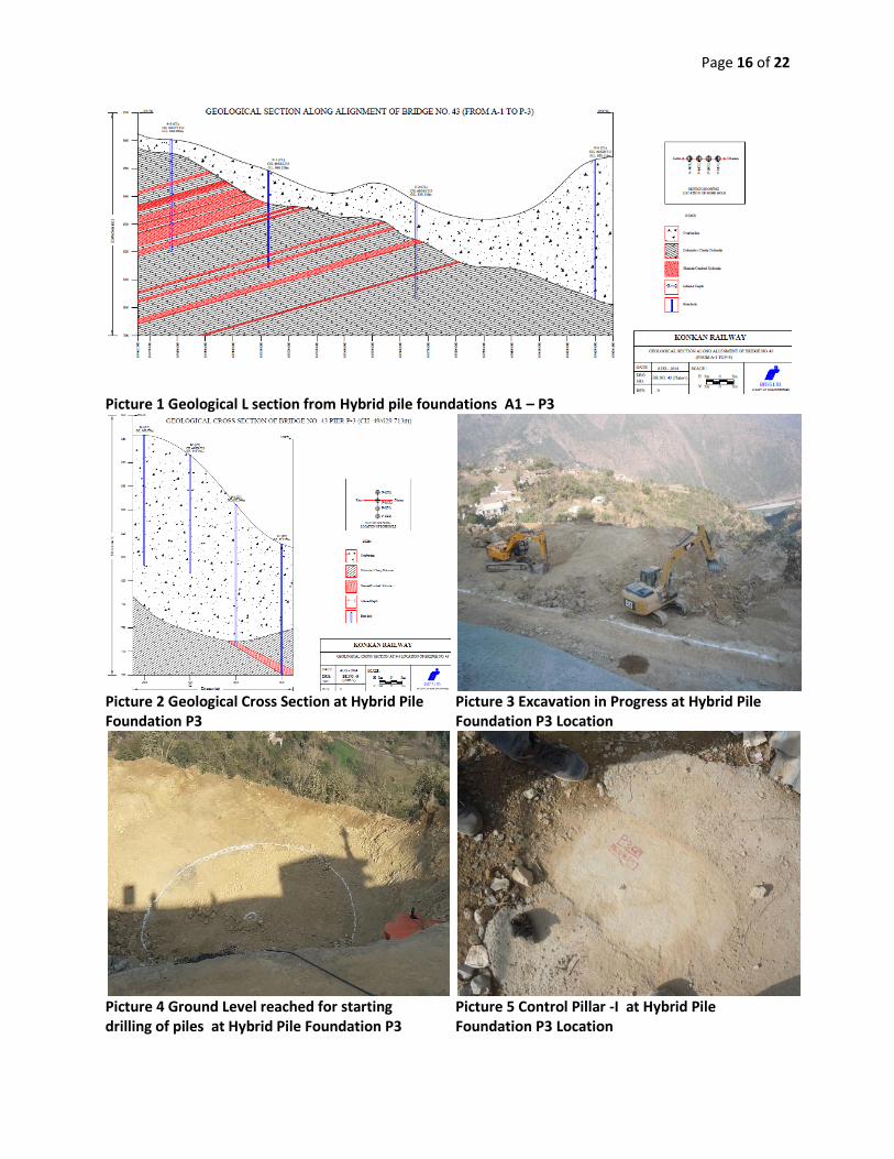
up slope area. Picture 1 shows geological L
section along hybrid pile foundations A1 to
P3. Picture 2 shows geological cross section
at hybrid pile foundation P3.
The report indicated that at Pier- P3, the bed
rock encountered at deeper depth of 37.20m
below ground surface at P3D2 location, at
58.00m below existing ground level at P3D1
location and bed rock not met up to explored
depth of 50.00m & 55.00m at P3CL & P3U1
locations respectively indicating thick cover
of slope debris material all along the slope.
The slope was quite steep in the middle part
due to presence of small exposures of
brecciated material also exposed along the
slope at places which was quite hard &
compact in nature but extended up to
shallow depth only (as per bore hole data).
The cutting of the slope was required to be
done in slope debris material and brecciated
material only at suitable angle with the
provision of berms in between two
consecutive slopes and required support
measures in the form of shotcreting, wire
mesh & rock bolting. The report
recommended to design the deep well / pile
foundation at this pier location and rested on
bed rock at deeper depth.
Further, the report recommended that the
cutting of slope should be done in proper
way by cutting of slope in a proper angle &
height and providing berms of suitable width
in between two consecutive slopes. The
overburden should be removed during
cutting of slope where bedrock is at shallow
depth and overhangs should be removed to
avoid any incident in the future.
Based on the geological, geotechnical
investigation reports and site visits to the
location of Bridge No. 43, the designer
RITES India and RAMBOLL Consultants of
Denmark designed the hybrid pile
foundations for abutment A1 and piers P1 to
P3. The proof checking of the design was
done by Anwikar Consultants, Germany.
3. EXCAVATION
The location where the hybrid pile
foundation P3 was to be constructed was not
directly available as it was overlain by soil
and rock. Therefore excavation had to be
done and access roads had to be created so
as to enable the manpower, machinery and
materials to provide the slope protection
measures and reach the sites of construction
of the hybrid pile foundation P3. The sites
were cleared of all the obstructions to enable
the setting out for excavation. Thereafter
survey points were marked on the ground
for excavation by considering the excavation
margin for subsequent works involved in the
construction of hybrid pile foundation P3.
The excavation had to be done in slopes and
berms as per the approved drawing. Figure 5

Page 3 of 22
and 6 shows the details of slopes and berms
which had to be achieved by the excavation.
For carrying out the protection works, berms
were created in the existing strata on which
the shotcrete spraying machine and Atlas
Copco ROC machine was used for
shotcreting and rock bolting of slopes
respectively. The excavators and/or
breakers were used for excavation in soils
and rocks and thereafter dumpers were used
to transport the excavated muck to the
designated dumping sites. Picture 3 shows
excavation in progress at the location of
hybrid pile foundation P3.
The steel fibre reinforced shotcrete of 100
mm thickness with fibre content of 40
kg/cum was provided on slopes in two
layers of 50 mm each, with the
reinforcement wire mesh of 100 mm x 100
mm x 3.15 mm dia conforming to IS:1566
with nominal mass of 1.25 kg/sq.m, in
between the two layers by wet shotcreting
method. The grade of Shotcrete was M25
and was to be applied on slopes as per
IS:9012:1997.
The rock bolts of 11 m length were provided
in the slopes with the Atlas Copco ROC
machine. The rock bolts were 32 mm in
diameter and of grade Fe500D. The rock
bolts were installed in 100 mm diameter
drilled holes and grouted with 30 MPa
cement grout. The orientation of the rock
bolts were decided by the geologist
considering the site conditions. The spacing
between the rock bolts was 1.5 m c/c
horizontally and vertically in the staggered
pattern. The protective coating of cement
inhibitor solution was applied on rock bolts
and bearing plate. The rock bolts were
tightened using torque wrench to generate an
axial tension equivalent to 25 percent of
design capacity of rock bolt (For 11 m long
rock bolts it comes out to be 5.75 tonnes).
One percent of working rock bolts of 11 m
lengths were to be tested up to 10 percent
more than the safe working load of 2
tonnes/m.
The weep holes were provided on slopes
@2.5 m c/c in both directions. Wherever the
distance of rock bolt was less, the weep
holes were located at the center of 4 rock
bolts.
The excavation was done at the location of
hybrid pile foundation P3 up to the ground
level just above the level where the
embedded reinforcement of piles had to
terminate in the top raft (i.e. 1.5 m above the
bottom of the top raft).
The total steel fibre reinforced shotcrete
provided was 1261 sq.m and total number of
rock bolts provided were 416.
Table 10 provides the details of number of
days taken to complete the excavation,
shotcreting and rock bolting for hybrid pile
foundation P3.
4. SURVEY AND LAYOUT MARKINGS
FOR PILES
The control pillars were established at the
site of hybrid pile foundation P3 after
excavation was completed to reach the
ground level just above the level where the
embedded reinforcement of piles had to
terminate in the top raft i.e around RL 841.5
m. Picture 4 shows the ground level reached
for starting drilling of piles of hybrid pile
foundation P3. The top level of the outer
piles was higher than that of the inner piles
but the founding level of all the piles was
same. The pile drilling for all the 153 piles

Page 4 of 22
was done from the same ground level. This
innovative working for drilling of piles
avoided the space constraints which would
have been encountered by the drilling rig
had the drilling of outer and inner piles been
done at different levels. The northing and
easting coordinates of the 153 piles were
determined in AUTOCAD software. Table 9
shows the survey coordinates of the 153
piles of the hybrid pile foundation P3.
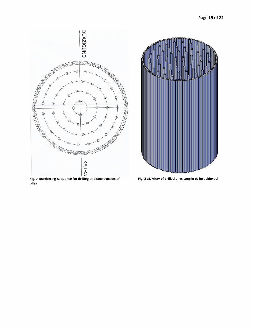
Figure 7 shows the numbering sequence of
these piles and Figure 8 shows the 3D
renditioned view of piling work sought to be
achieved. Proper planning was done for the
construction of these piles keeping in mind
the working space requirements at the site.
For construction of each pile, its survey
coordinates were staked on ground using the
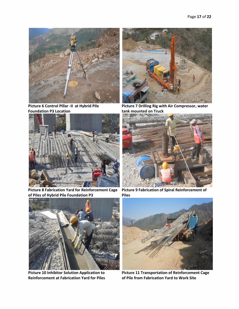
control pillars and total station. Picture 5 and
6 shows the control pillars used for staking
the coordinates of the piles on the ground.
5. DRILLING AND CONCRETING OF
PILES
The DTH 300-01 model drilling rig, water
tank and air compressor mounted on Ashok
Leyland Truck was used for drilling of piles.
Picture 7 shows the drilling rig with water
tank and air compressor mounted on the
truck used for drilling of piles at the hybrid
pile foundation P3 location. The operation
of drilling rig was done by 2 operators and 2
assistants. Recoverable steel casing of
diameter 390 mm was first drilled into the
soil as a temporary support and thereafter
the drilling bit mounted on drilling rod was
rotated inside the steel casing over the
staked coordinates of pile. The diamond
button head drilling bit of diameter 340 mm
was used for drilling. The compressed air
and/or water was sent down towards the
drilling bit through the annular space in the
drilling rods for flushing out the drill
cutting/slush. The soil and rock was
removed by the rotary and/or percussion
(hammering) action of the rotating drill bit.
The depth of excavation was increased by
further additions of the drilling rod at the
ends. The length of the first drilling rod
attached to the drilling bit was 2 m and the
lengths of subsequent drilling rods were 1.5
m. After reaching the design depths as
indicated in the drawing, the drilled hole
was cleaned, the water was pumped out of
the drilled bore and the drilling bit was taken
out. The depth of the bore hole was checked
by conducting the soundness test. The
excavated material was disposed off. The
diameter of outer and inner piles was 350
mm. The lengths of the constructed outer
and inner piles were 29.325 m and 22 m.
The concrete chipping of these constructed
piles was done keeping minimum 50 mm
above the bottom of the top raft and bottom
pile cap in case of outer and inner piles
respectively. The final lengths of piles were
29.3m and 20 m for outer and inner piles
respectively. The maximum progress of
drilling of piles achieved in 1 day was 4
piles but generally the progress achieved in
a day was 2-3 piles. The theoretical
quantities of the reinforcement steel and
concrete of grade M40 for each outer and
inner pile are given in Table 1.
The reinforcement cage for the pile was
fabricated at the fabrication yard. Picture 8
shows the fabrication yard for fabrication of
reinforcement cage of piles of hybrid pile
foundation P3. Picture 9 shows the
formation of spiral reinforcement of pile.
Page 5 of 22
Picture 10 shows the inhibitor solution
application over the reinforcement of piles.
Picture 11 shows the loading of
reinforcement cage in truck for transporting
it to the site of hybrid pile foundation P3.
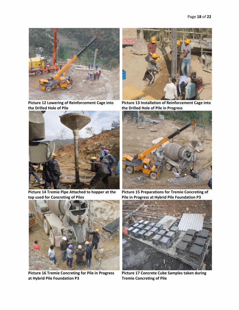
Picture 12 shows the lowering of
reinforcement cage in the drilled hole of the
pile of hybrid pile foundation P3. Picture 13
shows the closer look into the installation of
reinforcement cage into the bore hole.
For concreting of piles a special mix of M40
grade was developed with maximum
aggregate size of 10 mm. Table 3 shows the
constituents of concrete in M40 mix design.
The concreting of piles was done using
tremie pipe. The slump of concrete
measured at the site was generally 190 mm -
220 mm. Picture 14 shows the tremie pipe
attached to hopper at the top used for
concreting of piles. Picture 15 shows the
preparations being done for the tremie
concreting of pile. Picture 16 shows the
tremie concreting in progress for the pile.
Picture 17 shows the concrete cube samples
taken during tremie concreting of piles.
Table 4 shows the time cycle for the
construction of pile of hybrid pile
foundation P3.
6. CONSTRUCTION OF TOP RING
BEAM, BOTTOM PILE CAP AND
BOTTOM RING BEAM
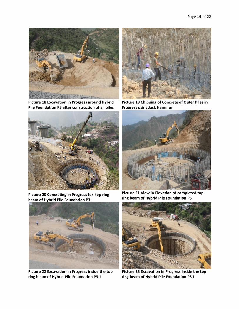
After completion of construction of 98 outer
piles and 55 inner piles of hybrid pile
foundation P3, the excavation was started
around the hybrid pile foundation P3.
Picture 18 shows the excavation in progress
around the hybrid pile foundation P3. The
excavation was done inside the hybrid pile
foundation P3 upto the bottom of the top raft
thereby exposing the outer piles. Thereafter,
the chipping of concrete of 98 outer piles
above the bottom level of top raft was done
using the jack hammer. Picture 19 shows the
chipping of concrete of outer piles in
progress at hybrid pile foundation P3.
Thereafter, excavation was done in the
inside portion of outer piles upto the bottom
level of the top ring beam. The
reinforcement binding was then started for
the the top ring beam around the outer 98
piles. Thereafter M35 grade concreting was
completed using bucket mounted on long
boom PC 300 crane and subsequently curing
was done. The width and the depth of the
top ring beam were 600 mm and 750 mm
respectively. Picture 20 shows the
concreting in progress for the top ring beam
using bucket and crane arrangement. Picture
21 shows the completed top ring beam in
elevation. After completion of top ring
beam, the excavation was started in the
inside area of the top ring beam for reaching
the bottom level of the bottom pile cap. The
excavation was done using excavators,
breakers and long boom PC 300 machines.
Pictures 22, 23 and 24 shows the excavation
in progress at the hybrid pile foundation P3
using excavators, breakers and long boom
PC 300 machines. The middle ring beam
and shotcrete lining on the inside face was
not provided considering the safe and stable
site conditions during excavations. The top
of the inner piles above the bottom level of
the bottom pile cap was chipped off keeping
minimum projection of 50 mm above that
level. Picture 25 shows the chipping of
concrete of inner piles in progress at the
hybrid pile foundation P3. The diameter and
Page 6 of 22
depth of the bottom pile cap were 13.1 m
and 2 m respectively. Picture 26 shows the
arrangement for bending of reinforcement at
the site of hybrid pile foundation P3. The
reinforcement of the bottom pile cap was
transported to the site of work using Hydra
crane. Picture 27 shows the reinforcement
being carried to the site of work using hydra
crane. Pictures 28, 29 and 30 shows
reinforcement binding in progress at
different stages for bottom pile cap of hybrid
pile foundation P3. Picture 31 shows the
concreting in progress for bottom pile cap.
After completion of the construction of the
bottom pile cap the reinforcement binding of
the bottom ring beam was completed. The
width and the depth of the bottom ring beam
were 500 mm and 750 mm respectively.
Thereafter construction of bottom ring beam
was completed. Table 3 shows the
constituents of concrete mix design of grade
M35 and M40 used for the construction of
top ring beam, bottom pile cap and bottom
ring beam.
7. PCC INFILLING AND
CONSTRUCTION OF TOP RAFT
The PCC infilling of 1:3:6 was completed
from the top level of the bottom pile cap up
to the bottom level of the top raft. The depth
of PCC infilling was 8 m and the quantity of
PCC was 1056 cum. Picture 32 shows the
PCC infilling in progress using the funnel
and canvas chute arrangement. Picture 33
shows the competed PCC upto the bottom of
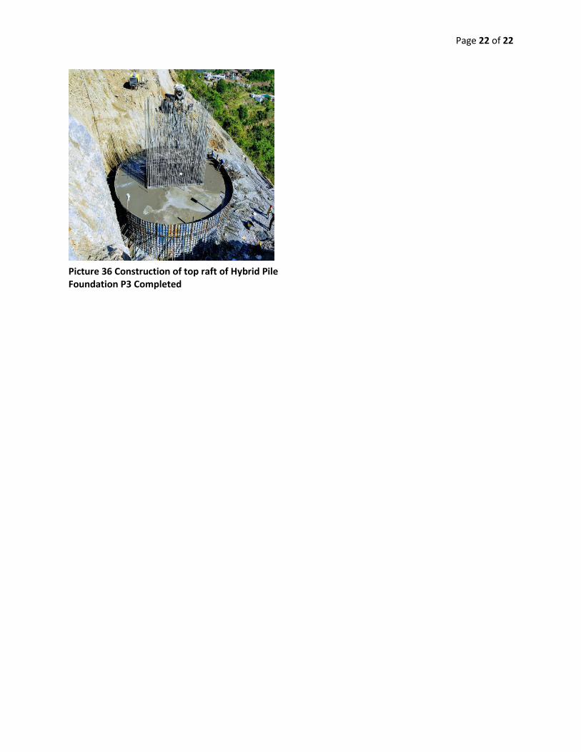
the top raft. On completion of PCC infilling
the process of construction of top raft was
started. The diameter and depth of the top
raft were 14 m and 3.2 m respectively.
Pictures 34 and 35 shows the reinforcement
binding in progress for the top raft of hybrid
pile foundation P3. Picture 36 shows the
completed top raft of hybrid pile foundation
P3.
8. REINFORCEMENT BINDING
The Bar Bending Schedule (BBS) was
prepared as per the approved drawings for
the piles, top ring beam, bottom pile cap,
bottom ring beam and top raft. The
reinforcement bars were then cut and bend
to the length, shape and numbers for each
bar mark/ID mark as given in the BBS. The
reinforcement bars were treated with anti
corrosive treatment by using inhibitor
solution. The reinforcement bars were then
tied in position to the spacing, lapping as
given in the BBS and in the approved
drawings. All reinforcing bars had to be
exactly placed in the position shown in the
drawings and had to be securely held in
position during placing of concrete by
galvanized steel binding wire not less than
18 SWG in diameter and conforming to IS
280 and by using stays, chairs, spacers,
metal hangers, supporting wires or other
approved devices at sufficiently close
intervals. Not more than 50 percent bars had
to be lapped at the same section i.e.
staggered lap splices. Lap splices are
staggered if the center to center spacing of
the splices is greater than or equal to 1.3
times the lap length. The distance between
the adjacent laps should be greater than or
equal to 150 mm.
9. FORMWORK
The piles of hybrid pile foundation P3 were
bored and cast in situ piles. The temporary
support of casing of internal diameter 390
Page 7 of 22
mm, thickness 10 mm and length of 2 m was
provided at the top only. When the caving in
of the sides of the bore hole happened, the
bore hole was filled with concrete and
drilling was resumed again after 24 hours.
The formwork of top and bottom ring beams
consisted of steel plates of dimensions 1.5 m
x 0.5 m and thickness 10 mm. These steel
plates were connected to each other by bolts
and laterally supported by channels and
props. Picture 20 shows the formwork
provided for the construction of top ring
beam.
The lateral support for the concreting of the
bottom cap was provided by the sides of
bore hole consisting of outer piles.
The formwork of the top raft consisted of
steel plates of dimensions 1.5 m x 0.5 m and
thickness 10 mm. These steel plates were
connected to each other by bolts and
laterally supported by channels, walers and
props. Picture 36 shows the formwork
provided for the construction of top raft.
10. CONCRETING METHODOLOGY
For the concreting of piles, the tremie
concreting methodology was adopted. The
diameter of the tremie pipe was 100 mm.
The tremie pipe was attached to the hopper
at its top on which concrete was fed from
the transit mixer. Picture 14 shows the
tremie pipe attached to hopper at the top.
The length of tremie pipe could be increased
by adding additional pipes. The concrete
was placed at the lower end of tremie pipe
keeping the lower end sufficiently deep into
the concrete which had been placed
previously but had not yet set. The
maximum size of aggregate in M40 mix was
kept as 10 mm to allow the free flow of
concrete through the tremie pipe of 100 mm.
After the placing of concrete was started the
lower end of the tremie pipe was to remain
within the top surface of plastic concrete in
order to allow the build up of concrete from
below instead of flowing over the surface.
For top and bottom ring beams, bucket and
crane concreting methodology was adopted.
The bucket of capacity 0.5 cum was attached
to the long boom PC 300 crane. The bucket
was filled with concrete from the transit
mixer and thereafter was moved to the site
of placement of concrete using the long
boom PC 300 machine.
The concreting of bottom cap was done
using three concreting methodologies i.e.
bucket and crane; pumps connected with
rigid pipes; funnel and canvas chutes. In the
pumps and rigid pipes methodology, the
concrete from the transit mixer was forced
into the rigid pipes through the concrete
pump. The other end of the rigid pipe was
connected to the flexible pipe which could
be moved around for placing the concrete
inside the reinforcement cage. In the funnel
and canvas chute arrangement, the concrete
from transit mixer was fed into the funnel
which was carried by gravity through the
canvas chutes to the location of placement
of concrete.
The concreting of the top raft was done
using rigid pipes and pumps. For details of
the concreting methodology adopted for the
top raft of hybrid pile foundation P3, the
readers are advised to refer paper by the
Author “CONSTRUCTION OF RAFT
FOUNDATIONS: THE CASE STUDIES
Page 8 of 22
OF RAFT FOUNDATIONS OF BRIDGE
NO. 43 AND 44 (CHENAB BRIDGE) AT
BAKKAL, USBRL PROJECT” published in
the IPWE proceedings 2019.
11. RESULTS
(i) Materials testing before concreting
The size, gradation and moisture content
tests for coarse aggregates were to be
conducted before each concreting day as
specified in the approved Quality Assurance
Plan (QAP) for civil works for Bridge No.
43. Similarly the tests for size, gradation, silt
content, moisture content of sand were to be
conducted as specified in the approved QAP
for civil works for Bridge No.43. All the
other tests on materials like cement,
aggregates, reinforcement bars, admixture,
water etc were carried out as per their
frequencies as specified in the QAPs for the
civil works for Bridge No.43. For
illustration purpose Table 5 shows the
results of sieve analysis of 10mm coarse
aggregate before the concreting of pile at
hybrid pile foundation P3.
(ii) Concrete Production at the batching
plant
The concrete for hybrid pile foundation P3
was produced at the batching plant of
capacities 30 cum per hour. The moisture
content of aggregates was determined and
the moisture corrections were incorporated
in the approved mix design at SSD
conditions. For illustration purpose Table 6
shows the moisture correction for concrete
mix of M40 grade before concreting of pile
of hybrid pile foundation P3. The calibration
of batching plant is to be done per month as
per the QAP for civil works for Bridge No.
43.
(iii) Cube strength test results
The cube samples were prepared at site
during concreting operations of hybrid pile
foundation P3 and thereafter taken to the
quality control laboratory at the site. Table 7
shows the 28 days cube strength test results
for the various concreting operations in
hybrid pile foundation P3.
(iv) Permeability test
The permeability test was conducted for the
concrete used in the construction of hybrid
pile foundation P3. For illustration purpose
Table 8 shows the results of permeability
test conducted for the pile of hybrid pile
foundation P3. Sample for permeability test
on concrete as per Appendix-G of IRS
Concrete Bridge Code was taken on
14.03.2018 for the pile no. 31 of hybrid pile
foundation P3. Test was conducted at
Quality Control Laboratory at Reasi as per
Appendix-G of IRS CBC on 15.04.2018 and
observations are given in Table 8. The
permissible value of permeability is 25 mm.
(v) Milestone Monitoring
The time periods pertaining to the milestone
achievements during the construction of
hybrid pile foundation P3 are presented in
Table 10.
12. CONCLUSIONS
(i) The workability of concrete as
measured by slump test was maintained as
per the design mix range/requirements of job
site in terms of the QAP for civil works for

Page 9 of 22
Bridge No. 43. For piles tremie concreting
was done. For top ring beam, bottom pile
cap, bottom ring beam and top raft, concrete
was poured in layers and each layer was
vibrated as it was placed.
(ii) After initial setting of top surface of
concrete, curing was started by sprinkling
with water, covering with wet hessian cloth
or ponding to reduce early dry shrinkage.
After the removal of the formwork the same
was covered with hessian cloth on the sides
and kept wet by sprinkling of water at
regular intervals to maintain the dampness
of the hessian cloth throughout the curing
period.
(iii) Quality of concrete used in the
construction of hybrid pile foundation P3 as
determined from the 28 days cube strength
test results as given in Table 7 and by
permeability test as given in Table 8 was in
the acceptable limits.
13. REFERENCES
(i) Indian Railway Standard
Concrete Bridge Code
(ii) IS 456:2000 Plain and
Reinforced concrete – Code of
Practice
(iii) IS 12070:1985(Reaffirmed in
1995) Code of Practice for
Design and Construction of
Shallow Foundations on Rocks
(iv) IS 2911-1-2 (2010) Design and
Construction of Pile
Foundations-Code of Practice,
Part 1: Concrete Piles, Section 2:
Bored Cast In -Situ Concrete
Piles
(v) IS 9012: 1978 (Reaffirmed in
2002) Recommended practice for
Shotcreting
(vi) IS 11309 (1985) Method of
Conducting Pull out test on
anchor bars and rock bolts
(vii) Data as provided at site and in
quality control laboratory at
Bakkal for Bridge No. 41, 42, 43.
(viii) Quality Assurance Plan(QAP)
for Civil Works for Bridge No.43
(ix) Method Statement for excavation
of Bridge 43 (A1 to P3) & Salal
Station Yard
(x) Report on Additional
Geotechnical Investigation for
Slope Stability of Bridge No. 43
on Katra – Dharam section of
USBRL Project
Table 1 Details of Hybrid Pile Foundation P3 - I
S.No. DESCRIPTION THEORETICAL QUANTITIES OF
CONCRETE (CUM) REINFORCEMENT (MT)
1 Single Outer Pile 2.821 1.266
2 Single Inner Pile 2.116 0.828
3 Total of all Piles 392.838 169.608
4 Top Ring Beam 18.941 7.019
5 Bottom Cap 262.232 88.56
6 Bottom Ring Beam 16.864 5.111
7 Top Raft 492.509 124.13
Page 10 of 22
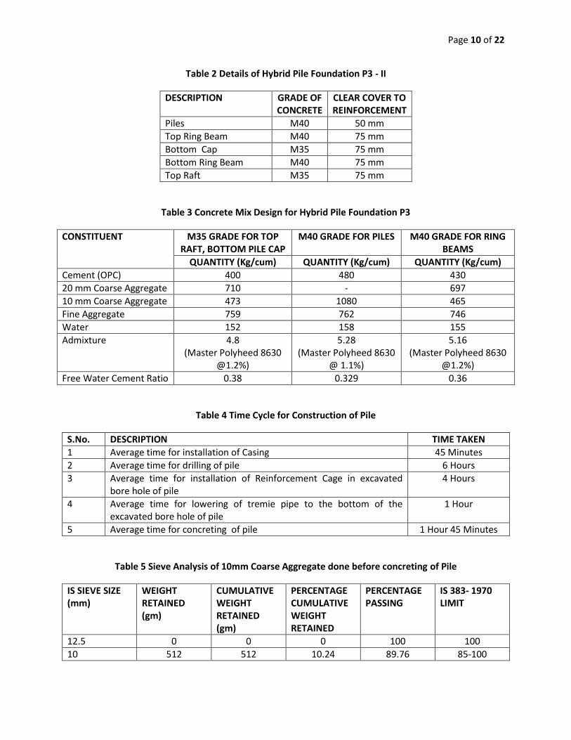
Table 2 Details of Hybrid Pile Foundation P3 - II
DESCRIPTION GRADE OF CONCRETE
CLEAR COVER TO REINFORCEMENT
Piles M40 50 mm
Top Ring Beam M40 75 mm
Bottom Cap M35 75 mm
Bottom Ring Beam M40 75 mm
Top Raft M35 75 mm
Table 3 Concrete Mix Design for Hybrid Pile Foundation P3
CONSTITUENT
M35 GRADE FOR TOP RAFT, BOTTOM PILE CAP
M40 GRADE FOR PILES M40 GRADE FOR RING BEAMS
QUANTITY (Kg/cum) QUANTITY (Kg/cum) QUANTITY (Kg/cum)
Cement (OPC) 400 480 430
20 mm Coarse Aggregate 710 - 697
10 mm Coarse Aggregate 473 1080 465
Fine Aggregate 759 762 746
Water 152 158 155
Admixture 4.8 (Master Polyheed 8630
@1.2%)
5.28 (Master Polyheed 8630
@ 1.1%)
5.16 (Master Polyheed 8630
@1.2%)
Free Water Cement Ratio 0.38 0.329 0.36
Table 4 Time Cycle for Construction of Pile
S.No. DESCRIPTION TIME TAKEN
1 Average time for installation of Casing 45 Minutes
2 Average time for drilling of pile 6 Hours
3 Average time for installation of Reinforcement Cage in excavated bore hole of pile
4 Hours
4 Average time for lowering of tremie pipe to the bottom of the excavated bore hole of pile
1 Hour
5 Average time for concreting of pile 1 Hour 45 Minutes
Table 5 Sieve Analysis of 10mm Coarse Aggregate done before concreting of Pile
IS SIEVE SIZE (mm)
WEIGHT RETAINED (gm)
CUMULATIVE WEIGHT RETAINED (gm)
PERCENTAGE CUMULATIVE WEIGHT RETAINED
PERCENTAGE PASSING
IS 383- 1970 LIMIT
12.5 0 0 0 100 100
10 512 512 10.24 89.76 85-100
Page 11 of 22
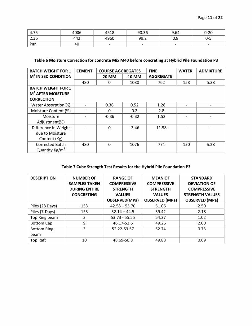
4.75 4006 4518 90.36 9.64 0-20
2.36 442 4960 99.2 0.8 0-5
Pan 40 - - - -
Table 6 Moisture Correction for concrete Mix M40 before concreting at Hybrid Pile Foundation P3
BATCH WEIGHT FOR 1 M3 IN SSD CONDITION
CEMENT COURSE AGGREGATES FINE AGGREGATE
WATER ADMIXTURE
20 MM 10 MM
480 0 1080 762 158 5.28
BATCH WEIGHT FOR 1 M3 AFTER MOISTURE CORRECTION
Water Absorption(%) - 0.36 0.52 1.28 - -
Moisture Content (%) - 0 0.2 2.8 - -
Moisture Adjustment(%)
- -0.36 -0.32 1.52 - -
Difference in Weight due to Moisture
Content (Kg)
- 0 -3.46 11.58 - -
Corrected Batch Quantity Kg/m3
480 0 1076 774 150 5.28
Table 7 Cube Strength Test Results for the Hybrid Pile Foundation P3
DESCRIPTION NUMBER OF SAMPLES TAKEN DURING ENTIRE
CONCRETING
RANGE OF COMPRESSIVE
STRENGTH VALUES
OBSERVED(MPa)
MEAN OF COMPRESSIVE
STRENGTH VALUES
OBSERVED (MPa)
STANDARD DEVIATION OF COMPRESSIVE
STRENGTH VALUES OBSERVED (MPa)
Piles (28 Days) 153 42.58 – 55.70 51.06 2.50
Piles (7-Days) 153 32.14 – 44.5 39.42 2.18
Top Ring beam 3 53.73 - 55.55 54.37 1.02
Bottom Cap 9 46.17-52.6 49.26 2.00
Bottom Ring beam
3 52.22-53.57 52.74 0.73
Top Raft 10 48.69-50.8 49.88 0.69

Page 12 of 22
Table 8 Permeability test result for Pile No. 31 of Hybrid Pile Foundation P3
SPECIMEN NUMBER
TEST START DATE
TIME TEST END DATE
TIME PRESSURE APPLIED(BAR)
PERMEABILITY MEASURED
VALUE (mm)
AVERAGE VALUE (mm)
1 11.04.2018
16.00 15.04.2018 16.00 1st 48 Hours: 1 Bar
Next 24 Hours: 3 Bar
Next 24 Hours: 7 Bar
6
6.67 2 11.04.2018
16.00 15.04.2018 16.00 8
3 11.04.2018
16.00 15.04.2018 16.00 6
Table 10 Milestone achievements in construction of Hybrid Pile Foundation P3
S.No. DESCRIPTION DATE OF STARTING
DATE OF COMPLETION
NUMBER OF DAYS TAKEN
1 Excavation for Hybrid Pile Foundation P3 01.10.2017 16.02.2018 51
2 Shotcrete 06.10.2017 21.02.2018 50
3 Rock Bolting 03.10.2017 18.02.2018 49
4 Piling for Hybrid Pile Foundation P3 17.02.2018 15.05.2018 88
5 Chipping of Outer Piles (98 no.s) 15.05.2018 31.05.2018 16
6 Excavation upto bottom level of top ring beam 15.05.2018 20.05.2018 5
7 Construction of top ring beam 31.05.2018 10.06.2018 11
8 Excavation upto bottom of bottom pile cap 22.06.2018 18.07.2018 27
9 Chipping of inner piles (55 no.s) 19.07.2018 25.07.2018 6
10 Construction of bottom pile cap 26.07.2018 18.08.2018 23
11 Construction of bottom ring beam 19.08.2019 21.08.2018 2
12 PCC infill from top of bottom pile cap and upto the bottom of top raft
20.08.2018 30.08.2018 10
13 Construction of top raft 31.08.2018 30.09.2018 30

Page 13 of 22
Table 9 Survey Coordinates of Piles of Hybrid Pile Foundation P3

Page 14 of 22
Fig.1 Hybrid Pile Foundation P3 in Plan
Fig.2 Hybrid Pile Foundation P3 in Elevation
Fig.3 Plan at the top raft level of Hybrid Pile Foundation P3
Fig.4 Plan at the Ring beam level of Hybrid Pile Foundation P3
Fig.5 Excavation in Cutting for Hybrid Pile Foundation P3 in Plan
Fig.6 Excavation in Cutting for Hybrid Pile Foundation P3 in Elevation
Page 15 of 22
Fig. 7 Numbering Sequence for drilling and construction of piles
Fig. 8 3D View of drilled piles sought to be achieved
Page 16 of 22
Picture 1 Geological L section from Hybrid pile foundations A1 – P3
Picture 2 Geological Cross Section at Hybrid Pile Foundation P3
Picture 3 Excavation in Progress at Hybrid Pile Foundation P3 Location
Picture 4 Ground Level reached for starting drilling of piles at Hybrid Pile Foundation P3
Picture 5 Control Pillar -I at Hybrid Pile Foundation P3 Location
Page 17 of 22
Picture 6 Control Pillar -II at Hybrid Pile Foundation P3 Location
Picture 7 Drilling Rig with Air Compressor, water tank mounted on Truck
Picture 8 Fabrication Yard for Reinforcement Cage of Piles of Hybrid Pile Foundation P3
Picture 9 Fabrication of Spiral Reinforcement of Piles
Picture 10 Inhibitor Solution Application to Reinforcement at Fabrication Yard for Piles
Picture 11 Transportation of Reinforcement Cage of Pile from Fabrication Yard to Work Site
Page 18 of 22
Picture 12 Lowering of Reinforcement Cage into the Drilled Hole of Pile
Picture 13 Installation of Reinforcement Cage into the Drilled Hole of Pile in Progress
Picture 14 Tremie Pipe Attached to hopper at the top used for Concreting of Piles
Picture 15 Preparations for Tremie Concreting of Pile in Progress at Hybrid Pile Foundation P3
Picture 16 Tremie Concreting for Pile in Progress at Hybrid Pile Foundation P3
Picture 17 Concrete Cube Samples taken during Tremie Concreting of Pile
Page 19 of 22
Picture 18 Excavation in Progress around Hybrid Pile Foundation P3 after construction of all piles
Picture 19 Chipping of Concrete of Outer Piles in Progress using Jack Hammer
Picture 20 Concreting in Progress for top ring beam of Hybrid Pile Foundation P3
Picture 21 View in Elevation of completed top ring beam of Hybrid Pile Foundation P3
Picture 22 Excavation in Progress inside the top ring beam of Hybrid Pile Foundation P3-I
Picture 23 Excavation in Progress inside the top ring beam of Hybrid Pile Foundation P3-II

Page 20 of 22
Picture 24 Excavation in Progress inside the top ring beam of Hybrid Pile Foundation P3-III
Picture 25 Chipping of Concrete of Inner Piles in Progress
Picture 26 Arrangements for Reinforcement Bending
Picture 27 Transportation of Reinforcement of Bottom Pile Cap
Picture 28 Reinforcement Binding in Progress at Bottom Cap-I
Picture 29 Reinforcement Binding in Progress at Bottom Cap-II

Page 21 of 22
Picture 30 Reinforcement Binding Completed at Bottom Pile Cap
Picture 31 Concreting in Progress at Bottom Pile Cap
Picture 32 PCC infilling in Progress at Hybrid Pile Foundation P3
Picture 33 PCC infilling Completed at Hybrid Pile Foundation P3
Picture 34 Reinforcement Binding in Progress at Top Raft of Hybrid Pile Foundation P3
Picture 35 Reinforcement Binding in Progress at Top Raft of Hybrid Pile Foundation P3
Page 22 of 22
Picture 36 Construction of top raft of Hybrid Pile Foundation P3 Completed