Embed Size (px)
Citation preview

Electronic Supplementary Material
Construction of hierarchical FeNi3@(Fe,Ni)S2 core–shell heterojunctions for advanced oxygen evolution Minglei Yan1, Zhiyang Zhao1, Peixin Cui2, Kun Mao1, Chi Chen3, Xizhang Wang1, Qiang Wu1, Hui Yang3, Lijun Yang1 (), and Zheng Hu1 ()
1 Key Laboratory of Mesoscopic Chemistry of MOE and Jiangsu Provincial Laboratory of Nanotechnology, School of Chemistry and Chemical
Engineering, Nanjing University, Nanjing 210023, China 2 Key Laboratory of Soil Environment and Pollution Remediation, Institute of Soil Science, the Chinese Academy of Sciences, Nanjing 210008,
China 3 Shanghai Advanced Research Institute, Chinese Academy of Sciences, Shanghai 201210, China
Supporting information to https://doi.org/10.1007/s12274-021-3531-8
Figure S1 The XRD patterns of the FeNi3, FeNi3@(Fe,Ni)S2-7.2 and (Fe,Ni)S2 samples.
The flat top of the XRD peaks may be ascribed to the co-existence of impurity phase of (Fe,Ni)S2-x (0<x<2) due to the incomplete sulfidization.
ICP analysis result of (Fe,Ni)S2
Element Content (mg L-1) Catalyst
Ni Fe Atom ratio of Ni/Fe
(Fe,Ni)S2 2.58 0.92 2.67
The XRD result indicates that the FeNi3@(Fe,Ni)S2-7.2 sample possesses two phases of cubic FeNi3 and (Fe,Ni)S2. The Ni/Fe ratio
in the control sample of (Fe,Ni)S2 is 2.67 (see ICP analysis result).
Address correspondence to Zheng Hu, [email protected]; Lijun Yang, [email protected]

Nano Res.
| www.editorialmanager.com/nare/default.asp
Figure S2 EDS elemental mapping of the typical FeNi3@(Fe,Ni)S2-7.2 core-shell structure in Figure 2e. (a) TEM image. (b-e) Elemental mapping images of Ni (b), Fe (c), S (d) and O (e), respectively.
The Ni and Fe elements show a high density in the core (Figure S2b,c), while the S element exhibits a high density in the shell. The O element comes from the surface oxidation.
Figure S3 XANES, EXAFS and wavelet transform of FeNi3@(Fe,Ni)S2-7.2. (a) Fe K-edge, (b) Ni K-edge. (c) EXAFS spectra. (d) wavelet transform of Fe. Note: The data for the control samples of FeNi3, (Fe,Ni)S2, Ni foil and Fe foil in (a-d) are presented for comparison. E0 is the absorbed edge energy of the Ni K-edge or Fe K-edge. The Fe K-edge for FeNi3 in (a) is re-plotted in (b) in dash line for convenient visual comparison.
The Fe K-edge of the FeNi3 is entirely different from that of the Fe foil, but coincides with that of the Ni foil, indicating its face-centered structure by partially substituting Ni for Fe, and the Fe atoms are isolated by Ni atoms with the atomic dispersion in FeNi3 alloy (Figure S3a,b)[1, 2]. The absorption edge position of X-ray absorption near-edge structure (XANES) is an indicator of the oxidation states[3]. From the evolution of Fe K-edge at the low-energy side, it is seen that the average valence of Fe species increases in the order of Fe foil < FeNi3 < FeNi3@(Fe,Ni)S2-7.2 < (Fe,Ni)S2 (Figure S3a). The higher Fe valence in FeNi3 than in Fe foil indicates the shift of electron cloud from Fe to Ni.
In the extended X-ray absorption fine structure (EXAFS) spectra of Fe K-edge associated with Figure S3a, a dominant peak (A) exists for all the samples corresponding to Fe-Fe/Ni bonds, while a minor peak (B) presents only for FeNi3@(Fe,Ni)S2-7.2 and (Fe,Ni)S2 matching with Fe-S bonds as expected (Figure S3c, Table S2). The wavelet transform (WT) analysis could give a radial distance resolution and the resolution in the k space[4]. For Fe foil, the maximum center at ca. 7.9 Å-1 is assigned to the Fe-Fe bonds (Figure S3d-I)[5]. For FeNi3 and (Fe,Ni)S2, the intensity maximum at ca. 8.1 and ca. 6.8 Å-1 are associated with the Fe-Fe/Ni and Fe-S bonds, respectively (Figure S3d-II, III). As expected, the WT contour plot of FeNi3@(Fe,Ni)S2-7.2 displays two intensity maximum at ca. 8.1 and ca. 6.8 Å-1, ascribed to the FeNi3 and (Fe,Ni)S2, respectively (Figure S3d-IV). The EXAFS and WT analysis confirm the coexistence of FeNi3 and (Fe,Ni)S2 in the FeNi3@(Fe,Ni)S2-7.2.

Nano Res.
www.theNanoResearch.com∣www.Springer.com/journal/12274 | Nano Research
EXAFS fitting results of Fe foil, FeNi3, (Fe,Ni)S2, FeNi3@(Fe,Ni)S2-7.2 and Ni foil Sample E0 (eV) Shells CN R(Å) σ2(Å2) R-factor
Fe foil, Fe k-edge 4.7 Fe-Fe 8 2.46 0.0049 0.0015 Fe-Fe 6 2.58 0.0049 FeNi3, Fe k-edge 6.9 Fe-Ni/Fe 9.3 2.50 0.0068 0.0029 (Fe,Ni)S2, Fe k-edge 1.7 Fe-S 5.4 2.28 0.0037 0.0012
FeNi3@(Fe,Ni)S2-7.2, Fe k-edge -3.8 Fe-S Fe-Ni
3.8 3.8
2.25 2.49
0.0097 0.0056 0.0009
FeNi3@(Fe,Ni)S2-7.2, Ni k-edge 0.8 Ni-S 3.6 2.32 0.0124 0.0001 Ni-Ni/Fe 3.5 2.50 0.0052 Ni foil, Ni k-edge 6.1 Ni-Ni 12 2.48 0.0059 0.0006
E0, inner potential correction; CN, coordination number, R, distance between absorber and backscatter atoms (bond length);
σ2, Debye-Waller factor to account for both thermal and structural disorders; R-factor indicates the goodness of the fit. Error bounds that characterize the structural parameters obtained by EXAFS spectroscopy were estimated as CN ±20%, R ±1%, σ2 ±20%, E0±20%. S0
2 was set to 0.85(Fe), 0.95(Ni) according to the Fe foil and Ni foil fits.
Figure S4 The calculated charge density difference in the heterojunction of FeNi3@(Fe,Ni)S2-7.2. The red and blue regions represent the charge depletion and accumulation in the space, respectively.
The calculation result demonstrates the electron transfer from FeNi3 to (Fe,Ni)S2 and the charge density redistribution on the heterointerfaces, which is supported by the XPS analysis (Figure 2i).
Figure S5 XPS spectra of FeNi3, FeNi3@(Fe,Ni)S2-7.2 and (Fe,Ni)S2 samples. (a) Ni2p. (b) Fe 2p.
The binding energies of Ni 2p and Fe 2p for the FeNi3@(Fe,Ni)S2-7.2 are in between the corresponding ones for the control samples of FeNi3 and (Fe,Ni)S2.
Figure S6 The conductivity of FeNi3, FeNi3@(Fe,Ni)S2-7.2 and (Fe,Ni)S2 samples.

Nano Res.
| www.editorialmanager.com/nare/default.asp
The conductivity of FeNi3@(Fe,Ni)S2-7.2 (525 S m-1) is much higher than that of (Fe,Ni)S2 (103 S m-1) and slightly lower than that of FeNi3 (579 S m-1).
Figure S7 N2 adsorption isotherms. (a) FeNi3. (b) FeNi3@(Fe,Ni)S2-3.6. (c) FeNi3@(Fe,Ni)S2-7.2. (d) FeNi3@(Fe,Ni)S2-10.8. (e) (Fe,Ni)S2.
The porous hierarchical FeNi3@(Fe,Ni)S2-n (n=3.6, 7.2, 10.8) samples possess large specific surface areas (74.5-78.1 m2 g-1).
Figure S8 The electrochemical results of the FeNi3@(Fe,Ni)S2-n (n=3.6, 7.2, 10.8), FeNi3 and (Fe,Ni)S2. (a) The polarization curves, (b) The corresponding Tafel plots. Note: The data for Ni foam and RuO2 are presented for comparison.
In general, the FeNi3@(Fe,Ni)S2-n (n=3.6, 7.2, 10.8) samples with core-shell structure have the better OER performance than those of the control samples of FeNi3 and (Fe,Ni)S2.
Figure S9 The EIS characterizations of FeNi3, FeNi3@(Fe,Ni)S2-7.2 and (Fe,Ni)S2 samples.

Nano Res.
www.theNanoResearch.com∣www.Springer.com/journal/12274 | Nano Research
The FeNi3@(Fe,Ni)S2-7.2 has the smallest charge-transfer resistance (Rct), indicating the best charge transfer kinetics.
Figure S10 The CV curves at different scan rates (a-c) and the linear relationship of peak currents versus scan rates (d) for FeNi3, FeNi3@(Fe,Ni)S2-7.2 and (Fe,Ni)S2.
The slope in Figure S10d was used to calculate the number of active sites M (mol) (Slope=n2F2M/4RT), which is used to calculate the TOF (TOF=A•j/4FM) (See Equation 4 &5 in EXPERIMENTAL SECTIONS).
Figure S11 The measurement of ECSAs and the corresponding ECSA-normalized polarization curves for FeNi3, FeNi3@(Fe,Ni)S2-n (n=3.6, 7.2, 10.8) and (Fe,Ni)S2 samples. (a-e) The CV curves at different scan rates of FeNi3 (a), FeNi3@(Fe,Ni)S2-3.6 (b), FeNi3@(Fe,Ni)S2-7.2 (c), FeNi3@(Fe,Ni)S2-10.8 (d) and (Fe,Ni)S2 (e). (f) The difference of current density at 1.18 V vs. the scan rate for the CV curves in (a-e). (g) The ECSA-normalized polarization curves.
Note: 1) The current density in (a-f) is normalized by the geometric area. 2) The double-layer capacitance (Cdl) for each sample was obtained by linearly fitting the curves in (f), which was used to
calculate the corresponding ECSA by ECSA=A·Cdl/Cs (See Equation 2 in EXPERIMENTAL SECTIONS).

Nano Res.
| www.editorialmanager.com/nare/default.asp
The trend of the ECSA-normalized polarization curves for the samples is in accordance with thoses normalized by the geometric area in Figure S8a. This result indicates that tuning the S/FeNi3 ratios could effectively regulate the intrinsic activity of the catalysts.
Figure S12 The mass activities of FeNi3, FeNi3@(Fe,Ni)S2-7.2 and (Fe,Ni)S2 at the overpotential of 300 mV.
The mass activity of the FeNi3@(Fe,Ni)S2-7.2 is evaluated to be 151 A g-1, much higher than those of the control samples for FeNi3 (29 A g-1) and (Fe,Ni)S2 (60 A g-1).
Figure S13 The OER performance of FeNi3@(Fe,Ni)S2-7.2 in alkaline (1M KOH) and neutral (1M PBS) medium. (a) The polarization curves obtained by sweeping the potential from 0 V to 0.8 V (vs Ag/AgCl) (black line) and 0.8 V to 0 V (vs Ag/AgCl) (red line) in 1M KOH. (b,c) The polarization curve (b) and corresponding Tafel plot (c) of FeNi3@(Fe,Ni)S2-7.2 in 1M PBS.
To avoid the influence of oxidation on the determination for the overpotential, we also performed the polarization curve of FeNi3@(Fe,Ni)S2-7.2 by sweeping the potential from 0.8 V to 0 V (vs Ag/AgCl). There is little difference of the overpotentials at 100 mA cm-2 for the two polarization curves (Figure S13a).
The OER performance of the FeNi3@(Fe,Ni)S2-7.2 in 1M PBS is moderate with a overpotential of 460 mV@10 mA cm-2 and a Tafel slope of 167 mV dec-1 (Figure S13b,c).
Figure S14 CP curve of FeNi3@(Fe,Ni)S2-7.2 at a constant high current density of 200 mA cm-2 for 1200 h.
The FeNi3@(Fe,Ni)S2-7.2 demonstrates an excellent stability during 1200 h test at a high current density of 200 mA cm-2.
Figure S15 XRD and Raman characterizations of FeNi3@(Fe,Ni)S2-7.2. (a) XRD before and after OER. (b) Raman spectrum after OER.

Nano Res.
www.theNanoResearch.com∣www.Springer.com/journal/12274 | Nano Research
XRD results show that the (Fe,Ni)S2 phase disappeared after 10 h operation, which is attributed to the transformation of the (Fe,Ni)S2 shell into the amorphous metal oxyhydroxides on the surface of the sample upon applying the potential (Figure S16).
Raman result shows that the NiOOH and FeOOH are formed on the surface of the FeNi3@(Fe,Ni)S2-7.2.
Figure S16 SEM and (HR)TEM characterizations of FeNi3@(Fe,Ni)S2-7.2 after 10 h stability test. (a,b) SEM images. (c,d) (HR)TEM images.
After 10 h stability test, the FeNi3@(Fe,Ni)S2-7.2 maintained the good structural integrity (a-c). This activation process leads to the formation of an amorphous layer on FeNi3@(Fe,Ni)S2-7.2 as shown by the HRTEM images in (d).
Figure S17 The OER mechanism, free-energy diagram and bandgap of the S-NixFe1-xOOH. (a,b) The OER mechanism (a) and corresponding reaction free-energy diagram (b). (c) The bandgap of S-NixFe1-xOOH. Note: The data for NiOOH and NixFe1-xOOH are presented for comparison.
The calculated thermodynamic theoretical overpotential of OER follows the order of S-NixFe1-xOOH < NixFe1-xOOH < NiOOH, indicating the enhancement of the intrinsic OER activity upon the introduction of S dopant. The smaller bandgap of S-NixFe1-xOOH than NixFe1-xOOH indicates the higher conductivity of the former, which is beneficial to the enhancement of OER activity.

Nano Res.
| www.editorialmanager.com/nare/default.asp
Figure S18 XRD patterns of Ni/NiFe2O4 and Co/CoP. (a) Ni/NiFe2O4. (b) Co/CoP.
The Ni/NiFe2O4 heterojunction was prepared by the post-treatment of the NiFe(OH)x precursor in the Ar atmosphere at 450 °C for 2 h. The Co/CoP heterojunction was synthesized by post-treatment of the Co(OH)x precursor with NaH2PO2 in the Ar atmosphere at 400 °C for 2 h.
Table S1 XPS fitting results
Samples Species Binding energy (eV) Refs FeNi3 Ni0 852.4 (2p3/2); 869.5 (2p1/2) [6]
Fe0 706.7 (2p3/2); 719.6 (2p1/2) [6]
FeNi3@(Fe,Ni)S2-7.2 Ni0 852.9 (2p3/2); 870.4 (2p1/2) [6] Ni of Ni-S 853.4 (2p3/2); 870.8 (2p1/2) [7] Fe0 707.0 (2p3/2); 719.9 (2p1/2) [6] Fe of Fe-S 707.2 (2p3/2); 720.0 (2p1/2) [7] S of FeNi3@(Fe,Ni)S2-7.2 161.3, 162.4,163.6,164.9 [8, 9] S of S-O 168.6 [8, 9]
(Fe,Ni)S2 Ni of Ni-S 853.7 (2p3/2); 871.3 (2p1/2) [7] Fe of Fe-S 707.4 (2p3/2); 720.2 (2p1/2) [7] S of (Fe,Ni)S2 161.6, 162.7,163.8,165.0 [8, 9] S of S-O 169.0 [8, 9]
Table S2 The OER performances for FeNi3@(Fe,Ni)S2-7.2 and the typical non-precious metal catalysts in literature
Catalysts Overpotential η (mV) @ 100 mA/cm2
Tafel slope (mV dec-1) Stability test Refs
FeNi3@(Fe,Ni)S2-7.2 288 48 1200 h @ 200 mA/cm2 This work (Ni, Fe)S2@MoS2 330 43.21 44 h @ 10 mA/cm2 [10]
CoNiSe2 307 79 20 h @ 100 mA/cm2 [11] N-NiMoO4/NiS2 335 44.3 29 h @ 1.53 V [12]
Ni-Fe-OH@Ni3S2/NF 240 93 50 h @ 500 mA/cm2 [13] Fe-O-Ni(OH)2/NF 220 32 50 h @ 500 mA/cm2 [14] MIL-53(FeNi)/NF ca. 245 31.3 4.44 h @ 100 mA/cm2 [15]
N-Ni3S2/NF 330 70 2.78 h @ 1.55 V [16] FeS2/CoS2 302 42 70 h @ 10 mA/cm2 [17]
Ni1.5Fe0.5P/CF 293 55 12 h @ 10 mA/cm2 [18] Ni(OH)2/Ni3S2 280 72 120 h @ 20 mA/cm2 [19]
NiTe/NiS 257 49 50 h @ 50 mA/cm2 [20] Co-NC/CF 330 72 100 h @ 20 mA/cm2 [21]
(Fe-Ni)Cox-OH/Ni3S2 280 57 100 h @ 200 mA/cm2 [22] FeNi-HDNAs 300 91.66 10 h @ 100 mA/cm2 [23]
NiFe(OH)x@Ni3S2/MoS 309 39 12 h @ 293 mV [24] Ni5Co3Mo-OH 304 56 100 h @ 100 mA/cm2 [25]
V-Ni3S2@NiFe LDH 286 32.5 24 h @ 100 mA/cm2 [26] NiFe LDH/graphene / 52 10 h @ 10 mA/cm2 [27]
Cu@CoFe LDH 300 44.4 24 h @ 10 mA/cm2 [28] NiFe(OH)x/FeS/IF 261 / 25 h @ 10 mA/cm2 [29]
hcp-NiFe@NC 263 41 35 h @ 20 mA/cm2 [30] Ni2P/Ni3S2 / 62 24 h @ 220 mV [31]
Note: NF: Nickel Foam; LDH: layered double hydroxide; HDNAs: Hydroxides nanotube arrays; IF: Iron foam; NGF: N-doped graphene foam; SG: sponge- like strutted graphenes; CF: carbon fiber
Nano Res.
www.theNanoResearch.com∣www.Springer.com/journal/12274 | Nano Research
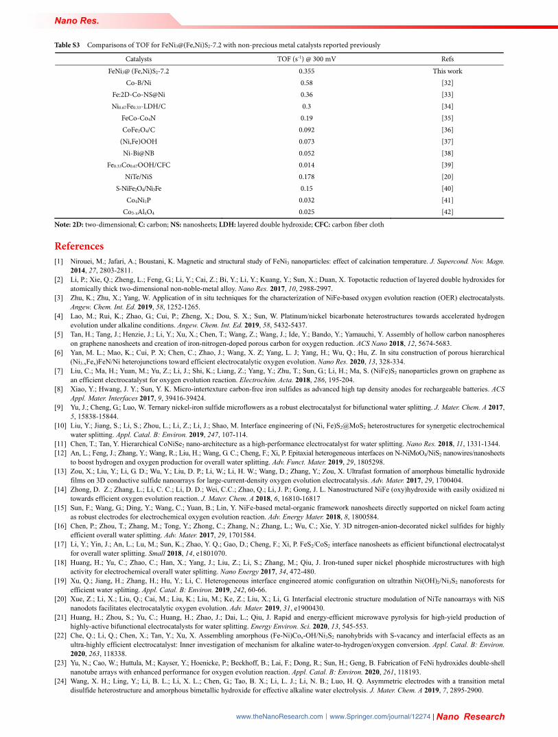
Table S3 Comparisons of TOF for FeNi3@(Fe,Ni)S2-7.2 with non-precious metal catalysts reported previously
Catalysts TOF (s-1) @ 300 mV Refs FeNi3@ (Fe,Ni)S2-7.2 0.355 This work
Co-B/Ni 0.58 [32] Fe:2D-Co-NS@Ni 0.36 [33] Ni0.67Fe0.33-LDH/C 0.3 [34]
FeCo-Co4N 0.19 [35] CoFe2O4/C 0.092 [36]
(Ni,Fe)OOH 0.073 [37] Ni-Bi@NB 0.052 [38]
Fe0.33Co0.67OOH/CFC 0.014 [39] NiTe/NiS 0.178 [20]
S-NiFe2O4/Ni3Fe 0.15 [40]
Co4Ni1P 0.032 [41]
Co3-xAlxO4 0.025 [42]
Note: 2D: two-dimensional; C: carbon; NS: nanosheets; LDH: layered double hydroxide; CFC: carbon fiber cloth
References [1] Nirouei, M.; Jafari, A.; Boustani, K. Magnetic and structural study of FeNi3 nanoparticles: effect of calcination temperature. J. Supercond. Nov. Magn.
2014, 27, 2803-2811. [2] Li, P.; Xie, Q.; Zheng, L.; Feng, G.; Li, Y.; Cai, Z.; Bi, Y.; Li, Y.; Kuang, Y.; Sun, X.; Duan, X. Topotactic reduction of layered double hydroxides for
atomically thick two-dimensional non-noble-metal alloy. Nano Res. 2017, 10, 2988-2997. [3] Zhu, K.; Zhu, X.; Yang, W. Application of in situ techniques for the characterization of NiFe-based oxygen evolution reaction (OER) electrocatalysts.
Angew. Chem. Int. Ed. 2019, 58, 1252-1265. [4] Lao, M.; Rui, K.; Zhao, G.; Cui, P.; Zheng, X.; Dou, S. X.; Sun, W. Platinum/nickel bicarbonate heterostructures towards accelerated hydrogen
evolution under alkaline conditions. Angew. Chem. Int. Ed. 2019, 58, 5432-5437. [5] Tan, H.; Tang, J.; Henzie, J.; Li, Y.; Xu, X.; Chen, T.; Wang, Z.; Wang, J.; Ide, Y.; Bando, Y.; Yamauchi, Y. Assembly of hollow carbon nanospheres
on graphene nanosheets and creation of iron-nitrogen-doped porous carbon for oxygen reduction. ACS Nano 2018, 12, 5674-5683. [6] Yan, M. L.; Mao, K.; Cui, P. X; Chen, C.; Zhao, J.; Wang, X. Z; Yang, L. J; Yang, H.; Wu, Q.; Hu, Z. In situ construction of porous hierarchical
(Ni3-xFex)FeN/Ni heterojunctions toward efficient electrocatalytic oxygen evolution. Nano Res. 2020, 13, 328-334. [7] Liu, C.; Ma, H.; Yuan, M.; Yu, Z.; Li, J.; Shi, K.; Liang, Z.; Yang, Y.; Zhu, T.; Sun, G.; Li, H.; Ma, S. (NiFe)S2 nanoparticles grown on graphene as
an efficient electrocatalyst for oxygen evolution reaction. Electrochim. Acta. 2018, 286, 195-204. [8] Xiao, Y.; Hwang, J. Y.; Sun, Y. K. Micro-intertexture carbon-free iron sulfides as advanced high tap density anodes for rechargeable batteries. ACS
Appl. Mater. Interfaces 2017, 9, 39416-39424. [9] Yu, J.; Cheng, G.; Luo, W. Ternary nickel-iron sulfide microflowers as a robust electrocatalyst for bifunctional water splitting. J. Mater. Chem. A 2017,
5, 15838-15844. [10] Liu, Y.; Jiang, S.; Li, S.; Zhou, L.; Li, Z.; Li, J.; Shao, M. Interface engineering of (Ni, Fe)S2@MoS2 heterostructures for synergetic electrochemical
water splitting. Appl. Catal. B: Environ. 2019, 247, 107-114. [11] Chen, T.; Tan, Y. Hierarchical CoNiSe2 nano-architecture as a high-performance electrocatalyst for water splitting. Nano Res. 2018, 11, 1331-1344. [12] An, L.; Feng, J.; Zhang, Y.; Wang, R.; Liu, H.; Wang, G. C.; Cheng, F.; Xi, P. Epitaxial heterogeneous interfaces on N-NiMoO4/NiS2 nanowires/nanosheets
to boost hydrogen and oxygen production for overall water splitting. Adv. Funct. Mater. 2019, 29, 1805298. [13] Zou, X.; Liu, Y.; Li, G. D.; Wu, Y.; Liu, D. P.; Li, W.; Li, H. W.; Wang, D.; Zhang, Y.; Zou, X. Ultrafast formation of amorphous bimetallic hydroxide
films on 3D conductive sulfide nanoarrays for large-current-density oxygen evolution electrocatalysis. Adv. Mater. 2017, 29, 1700404. [14] Zhong, D. Z.; Zhang, L.; Li, C. C.; Li, D. D.; Wei, C.C.; Zhao, Q.; Li, J. P.; Gong, J. L. Nanostructured NiFe (oxy)hydroxide with easily oxidized ni
towards efficient oxygen evolution reaction. J. Mater. Chem. A 2018, 6, 16810-16817 [15] Sun, F.; Wang, G.; Ding, Y.; Wang, C.; Yuan, B.; Lin, Y. NiFe-based metal-organic framework nanosheets directly supported on nickel foam acting
as robust electrodes for electrochemical oxygen evolution reaction. Adv. Energy Mater. 2018, 8, 1800584. [16] Chen, P.; Zhou, T.; Zhang, M.; Tong, Y.; Zhong, C.; Zhang, N.; Zhang, L.; Wu, C.; Xie, Y. 3D nitrogen-anion-decorated nickel sulfides for highly
efficient overall water splitting. Adv. Mater. 2017, 29, 1701584. [17] Li, Y.; Yin, J.; An, L.; Lu, M.; Sun, K.; Zhao, Y. Q.; Gao, D.; Cheng, F.; Xi, P. FeS2/CoS2 interface nanosheets as efficient bifunctional electrocatalyst
for overall water splitting. Small 2018, 14, e1801070. [18] Huang, H.; Yu, C.; Zhao, C.; Han, X.; Yang, J.; Liu, Z.; Li, S.; Zhang, M.; Qiu, J. Iron-tuned super nickel phosphide microstructures with high
activity for electrochemical overall water splitting. Nano Energy 2017, 34, 472-480. [19] Xu, Q.; Jiang, H.; Zhang, H.; Hu, Y.; Li, C. Heterogeneous interface engineered atomic configuration on ultrathin Ni(OH)2/Ni3S2 nanoforests for
efficient water splitting. Appl. Catal. B: Environ. 2019, 242, 60-66. [20] Xue, Z.; Li, X.; Liu, Q.; Cai, M.; Liu, K.; Liu, M.; Ke, Z.; Liu, X.; Li, G. Interfacial electronic structure modulation of NiTe nanoarrays with NiS
nanodots facilitates electrocatalytic oxygen evolution. Adv. Mater. 2019, 31, e1900430. [21] Huang, H.; Zhou, S.; Yu, C.; Huang, H.; Zhao, J.; Dai, L.; Qiu, J. Rapid and energy-efficient microwave pyrolysis for high-yield production of
highly-active bifunctional electrocatalysts for water splitting. Energy Environ. Sci. 2020, 13, 545-553. [22] Che, Q.; Li, Q.; Chen, X.; Tan, Y.; Xu, X. Assembling amorphous (Fe-Ni)Cox-OH/Ni3S2 nanohybrids with S-vacancy and interfacial effects as an
ultra-highly efficient electrocatalyst: Inner investigation of mechanism for alkaline water-to-hydrogen/oxygen conversion. Appl. Catal. B: Environ. 2020, 263, 118338.
[23] Yu, N.; Cao, W.; Huttula, M.; Kayser, Y.; Hoenicke, P.; Beckhoff, B.; Lai, F.; Dong, R.; Sun, H.; Geng, B. Fabrication of FeNi hydroxides double-shell nanotube arrays with enhanced performance for oxygen evolution reaction. Appl. Catal. B: Environ. 2020, 261, 118193.
[24] Wang, X. H.; Ling, Y.; Li, B. L.; Li, X. L.; Chen, G.; Tao, B. X.; Li, L. J.; Li, N. B.; Luo, H. Q. Asymmetric electrodes with a transition metal disulfide heterostructure and amorphous bimetallic hydroxide for effective alkaline water electrolysis. J. Mater. Chem. A 2019, 7, 2895-2900.

Nano Res.
| www.editorialmanager.com/nare/default.asp
[25] Hao, S.; Chen, L.; Yu, C.; Yang, B.; Li, Z.; Hou, Y.; Lei, L.; Zhang, X. Nicomo hydroxide nanosheet arrays synthesized via chloride corrosion for overall water splitting. ACS Energy Lett. 2019, 4, 952-959.
[26] Zhou, J.; Yu, L.; Zhu, Q.; Huang, C.; Yu, Y. Defective and ultrathin NiFe LDH nanosheets decorated on V-doped Ni3S2 nanorod arrays: A 3D core-shell electrocatalyst for efficient water oxidation. J. Mater. Chem. A 2019, 7, 18118-18125.
[27] Jia, Y.; Zhang, L.; Gao, G.; Chen, H.; Wang, B.; Zhou, J.; Soo, M. T.; Hong, M.; Yan, X.; Qian, G.; Zou, J.; Du, A.; Yao, X. A heterostructure coupling of exfoliated Ni-Fe hydroxide nanosheet and defective graphene as a bifunctional electrocatalyst for overall water splitting. Adv. Mater. 2017, 29, 1-8.
[28] Yu, L.; Zhou, H.; Sun, J.; Qin, F.; Luo, D.; Xie, L.; Yu, F.; Bao, J.; Li, Y.; Yu, Y.; Chen, S.; Ren, Z. Hierarchical Cu@CoFe layered double hydroxide core-shell nanoarchitectures as bifunctional electrocatalysts for efficient overall water splitting. Nano Energy 2017, 41, 327-336.
[29] Niu, S.; Jiang, W. J.; Tang, T.; Yuan, L. P.; Luo, H.; Hu, J. S. Autogenous growth of hierarchical NiFe(OH)x/FeS nanosheet‐on‐microsheet arrays for synergistically enhanced high-output water oxidation. Adv. Funct. Mater. 2019, 29, 1902180.
[30] Wang, C.; Yang, H.; Zhang, Y.; Wang, Q. NiFe alloy nanoparticles with hcp crystal structure stimulate superior oxygen evolution reaction electrocatalytic activity. Angew. Chem. Int. Ed. 2019, 58, 6099-6103.
[31] Zeng, L.; Sun, K.; Wang, X.; Liu, Y.; Pan, Y.; Liu, Z.; Cao, D.; Song, Y.; Liu, S.; Liu, C. Three-dimensional-networked Ni2P/Ni3S2 heteronanoflake arrays for highly enhanced electrochemical overall-water-splitting activity. Nano Energy 2018, 51, 26-36.
[32] Hao, W.; Wu, R.; Zhang, R.; Ha, Y.; Chen, Z.; Wang, L.; Yang, Y.; Ma, X.; Sun, D.; Fang, F.; Guo, Y. Electroless plating of highly efficient bifunctional boride-based electrodes toward practical overall water splitting. Adv. Energy Mater. 2018, 8, 1801372.
[33] Huang, J.; Li, Y.; Huang, R. K.; He, C. T.; Gong, L.; Hu, Q.; Wang, L.; Xu, Y. T.; Tian, X. Y.; Liu, S. Y.; Ye, Z. M.; Wang, F.; Zhou, D. D.; Zhang, W. X.; Zhang, J. P. Electrochemical exfoliation of pillared-layer metal-organic framework to boost the oxygen evolution reaction. Angew. Chem. Int. Ed. 2018, 57, 4632-4636.
[34] Yin, S.; Tu, W.; Sheng, Y.; Du, Y.; Kraft, M.; Borgna, A.; Xu, R. A highly efficient oxygen evolution catalyst consisting of interconnected nickel-iron- layered double hydroxide and carbon nanodomains. Adv. Mater. 2018, 30, 1705106.
[35] Zhu, X.; Jin, T.; Tian, C.; Lu, C.; Liu, X.; Zeng, M.; Zhuang, X.; Yang, S.; He, L.; Liu, H.; Dai, S. In situ coupling strategy for the preparation of FeCo alloys and Co4N hybrid for highly efficient oxygen evolution. Adv. Mater. 2017, 29, 1704091.
[36] Lu, X. F.; Gu, L. F.; Wang, J. W.; Wu, J. X.; Liao, P. Q.; Li, G. R. Bimetal-organic framework derived CoFe2O4/C porous hybrid nanorod arrays as high-performance electrocatalysts for oxygen evolution reaction. Adv. Mater. 2017, 29, 1604437.
[37] Zhou, H.; Yu, F.; Zhu, Q.; Sun, J.; Qin, F.; Yu, L.; Bao, J.; Yu, Y.; Chen, S.; Ren, Z. Water splitting by electrolysis at high current densities under 1.6 volts. Energy Environ. Sci. 2018, 11, 2858-2864.
[38] Jiang, W. J.; Niu, S.; Tang, T.; Zhang, Q. H.; Liu, X. Z.; Zhang, Y.; Chen, Y. Y.; Li, J. H.; Gu, L.; Wan, L. J.; Hu, J. S. Crystallinity-modulated electrocatalytic activity of a nickel(ii) borate thin layer on Ni3B for efficient water oxidation. Angew. Chem. Int. Ed. 2017, 56, 6572-6577.
[39] Ye, S. H.; Shi, Z. X.; Feng, J. X.; Tong, Y. X.; Li, G. R. Activating CoOOH porous nanosheet arrays by partial iron substitution for efficient oxygen evolution reaction. Angew. Chem. Int. Ed. 2018, 57, 2672-2676.
[40] Gao, M. Y.; Zeng, J. R.; Zhang, Q. B.; Yang, C.; Li, X. T.; Hua, Y. X.; Xu, C. Y. Scalable one-step electrochemical deposition of nanoporous amorphous S-doped NiFe2O4/Ni3Fe composite films as highly efficient electrocatalysts for oxygen evolution with ultrahigh stability. J. Mater. Chem. A 2018, 6, 1551-1560.
[41] Yan, L.; Cao, L.; Dai, P.; Gu, X.; Liu, D.; Li, L.; Wang, Y.; Zhao, X. Metal-organic frameworks derived nanotube of nickel-cobalt bimetal phosphides as highly efficient electrocatalysts for overall water splitting. Adv. Funct. Mater. 2017, 27, 1703455.
[42] Wang, X.; Sun, P.; Lu, H.; Tang, K.; Li, Q.; Wang, C.; Mao, Z.; Ali, T.; Yan, C. Aluminum-tailored energy level and morphology of Co3-xAlxO4 porous nanosheets toward highly efficient electrocatalysts for water oxidation. Small 2019, 15, e1804886.