Embed Size (px)
Citation preview

AN ISO 9001 & ISO 14001 COMPANY
TENDER DOCUMENT TENDER No.: EPI/WRO/CON/662D/0004
FOR
CONSTRUCTION OF FACE LIFTING AND RENNOVATION OF MAIN INSTITUTIONAL BUILDING AT EXISTING CAPMUS OF
NIT, RAIPIR (CHHATTISGARH)
Technical Specifications
EXECUTING AGENCY :
ENGINEERING PROJECTS (INDIA) LIMITED (A GOVT. OF INDIA ENTERPRISE)
6A, 6th Floor, ‘BAKHTAWAR’ Nariman Point, Mumbai – 400 021 TEL NO: 022- 22049230, FAX NO. 022 – 22882177

SignatureofContractor 2EPI
PECIFICATION FOR CIVIL WORKS 1.0 GENERAL 1.01 Unless otherwise specified in the nomenclature of individual item or in the specifications,
for all works mentioned in this tender, the specifications and mode of measurements shall be in accordance with C.P.W.D. specifications 2009 Volume I to VI with upto date correction slips upto the date of tender. For the item not covered under CPWD specifications mentioned above, the work shall be executed as per latest relevant standards / codes published by B.I.S (formerly ISI) inclusive of all amendments issued thereto or revision thereof, if any, upto the date of submission of tender. All mandatory tests specified in CPWD specifications with upto date correction slips shall be carried out from the approved laboratories as desired by Architect / Engineer in charge of EPI. Testing charges including cartage, conveyance etc whatsoever shall be borne by the successful bidder. If after any such test and in the opinion of the Architect / Engineer In-charge of EPI any work is found defective or unsound, the same shall have to be dismantled and to be redone by the successful bidder at their own cost.
In case of BIS (formerly ISI) codes / specifications are not available for any item of work the decision of the Engineer based on acceptable sound engineering practice and local usage shall be final and binding on the successful bidder.
1.02 The rates for different items of work shall be for all heights, lifts, leads and depths except where otherwise specified in the item of work or in additional conditions appended with the tender.
1.03 The work shall be carried out in accordance with the approved drawings. The drawings shall have to be properly co-related before executing the work. In case of any difference noticed between the drawings, final decision, in writing of the Engineer-in-Charge shall be obtained by the contractor. For items, where so required, samples shall be prepared before starting the particular items of work for prior approval of the Engineer and nothing extra shall be payable on this account.
1.04 Unless otherwise specified in the bill of quantities or drawings, the rates for all the items of work shall be considered as inclusive of pumping out water if required for which no extra payment will be made. This will include water encountered from any source such as rains, floods, sub-soil water table being high or due to any other cause whatsoever.
1.05 Any cement slurry added over base surface (or) for continuation of concreting for bond the cost for the same is deemed to have in built in the item unless otherwise / explicitly stated and nothing extra shall be payable or extra cement considered for consumption on this account.
1.06 The rates for all items in which the use of cement is involved in inclusive of charges for curing.
1.07 The contractor shall clear the site thoroughly of al scaffolding materials and rubbish etc. left out of his work dressed the site to the satisfaction of the Engineer before the work is considered as complete.
1.08 The rate quoted for all brick / concrete work shall be deemed to include making openings and making good these with the same specifications as shown in drawings and / or as directed. No extra payment shall be made to the contractor on this account.
1.09 The quoted rate shall be for finished items and shall be complete in all respects including the cost of all material, labour tools & plants, machinery etc. all taxes, duties, levies, octroi, royalty charges, statutory levies, labour cess etc. applicable from time to time and any other item required but not mentioned here involved in the operations described above. EPI shall not be supplying any materials, labour, plant etc. unless explicitly mentioned so.

1.10 Random Rubble Masonry retaining wall shall be constructed as per approve drawings based on different heights at different locations and payment for the same shall be made as per the rates of respective items available in the Bill of Quantities.
1.11 Rate for plastering work (excluding washed stone grit plaster on external wall surface) shall include for making grooves, bands etc. wherever required and nothing extra shall be paid for the same.
1.12 Rates for all concrete / plaster work shall include for making drip course molding, grooves etc. wherever required and nothing extra shall be paid for the same.
2.0 SCOPE OF WORK
RCC framed structure incorporating recommendations from latest CPWD Specifications / National Building Codes.
RCC Raft foundation / isolated footing as per latest CPWD Specifications / National Building Codes.
Infill to frame with First Class Brickwork as per CPWD Specification / relevant BIS Code.
Random Rubble Masonry / Stone Masonry Work as per latest CPWD Specifications / National Building Codes.
3.0 CIVIL FINISHES
Civil finishes shall be as mentioned in the relevant drawings, specifications and schedule of finishes.
3.1 The bidder shall be responsible for structural soundness of the building / project in all respect and a certificate thereon shall be furnished by the bidder to EPI on the completion of the work.
4.0 MATERIAL
All materials shall be of standard quality and from approved manufacturer, conforming to Indian Standards or equivalent and shall have IS Mark as far as possible unless otherwise approved by Engineer-in-Charge. The contractor shall get all materials approved by Engineer-in-Charge prior to procurement and use. The contractor shall furnish manufacturers certificates, for the material supplied by him when asked for. Further to that he shall get all the materials tested from an approved test house, if asked for by the Engineer-in-Charge. The cost for all tests and test certificates shall be borne by the contractor. No separate payment shall be made for the testing. The Engineer-in-Charge shall have the right to determine whether all or any material are suitable. If any material procured or brought to site found not conforming to specifications and satisfaction of Engineer-in-Charge, the contractor shall have to remove the same immediately from the site at his own expense and without any claim for compensation due to such rejection. The contractor shall submit documentary evidence e.g. challans, bills etc. against the construction materials brought to site as a check to ensure that the required quantities as required for execution of works as per specification have been brought to site for incorporation in the work. The contractor shall ensure that the bought out materials are brought to site in original sealed containers or packing bearing name of manufacturer and brand.
4.1 BRICKS: The bricks shall be of approved quality having a minimum compressive strength
of 75 Kg / cm2, best quality locally available, well burnt, sound and of uniform quality and colour. These shall be free from salt and of standard size and shall conform to IS: 1077. The water absorption shall not be more 20% of its dry weight when soaked in cold water for 24 hours, as per IS: 3102. The tolerance limit shall be 3% for absorption.

SignatureofContractor 4EPI
The brick sample taken at random from the lot shall be deposited with, and be approved by the Engineer-in-Charge before being used. All subsequent deliveries shall be upto the standards of the approved sample.
4.4 COARSE AGGREGATE
Aggregate of sizes between 4.75 mms to 150 mms will be termed as coarse aggregate. Coarse aggregate from approved quarries and conforming to IS: 383 will only be allowed to be used for the works. Coarse aggregate for reinforced concrete work shall consists of approved broken stone aggregate free from flat laminated or elongated pieces and shall be free from any organic material and shall be within the limits of the relative grading in IS – 383 table – II. Unless otherwise shown on the drawings all coarse aggregate in reinforced concrete shall be graded crushed stone aggregate of 20mm nominal size. For plain cement concrete 40 mm down / 20 mm down coarse aggregate as per IS : 383 shall be used as per instructions of Engineer-in-Charge. For damp proof coarse / screed concrete above roof slab 12 mm down coarse aggregate as per IS : 383 shall be used.
4.5 FINE AGGREGATE
Aggregate smaller than 4.75mm and within the grading limits and other requirements set in IS: 383 is termed as Fine aggregate or sand. Fine aggregate from approved sources and conforming to the above IS specification shall only be allowed to be used for the works. For reinforced concrete, plain cement concrete, Brick work, damp proof coarse, screed concrete etc. sand of zone I & II shall only be used. Sand shall be clean river or pit sand of approved quality and shall be free from salts, earth dust or others impurities. It shall be washed with clean water and not more than 5% fine materials shall be allowed by settlement in water and passing through 10,000 mesh sieve. For plasters sand of zone – II / zone – III shall be used as per instructions of Engineer-in-Charge.
4.6 Water: Water shall be clean and reasonably free from injurious deleterious materials,
generally potable water shall be used. 5.0 OTHER MATERIALS
All materials not fully specified herein and which may be used in the work shall be approved by the Engineer-in-Charge and he shall have right to determine whether all or any of the materials offered or delivered for use in the work are suitable for the purpose. Contractor shall give the samples of materials to Engineer-in-Charge and shall get it approved before procurement and use.
6.0 PLAIN AND REINFORCED CONCRETE
This section of the specification deals with cement concrete plain or reinforced for general use and covers the requirements for concrete mix design, strength and quality, pouring at all levels, form work, protection, covering, finishing, admixtures, inserts, and other miscellaneous works. The provision of the latest version of IS : 456 shall be compiled with unless permitted otherwise and any other Indian Standard Code (Latest Revision) shall form part of the specification to the extent it has referred to or applicable within this specification.

6.1 GRADE OF CONCRETE All reinforced concrete shall be design mix concrete and of grade M – 25 unless otherwise specified in drawing. Nominal mix concrete proportioned for a given specified grade including cases where the Engineer-in-Charge directs use of additional cement over the quantity specified for the particular grade, shall not, however, be placed in a higher grade on the ground that the test strengths are higher than the minimum specified for the desired grade.
6.2 MIX PROPORTIONS
The mix proportions for grades of concrete specified in drawings shall be designed to obtain strength corresponding to the values specified in IS : 456 for respective grades of concrete. The minimum quantities of cement shall be as specified in Table-I or Preliminary tests, as specified in the IS code or as required by the Engineer-in-Charge, shall be carried out sufficiently ahead of the actual commencement of the work with different grades of concrete made from representative sample of aggregate and cement expected to be used on the job to ascertain the ratios by weight of cement to total aggregate, of fine to coarse aggregate and water cement ratio required to produce a concrete having specified strength and sufficient workability to enable it to be well consolidated and to be worked into corners of shuttering and around the reinforcement.
6.3 WORKMANSHIP
All workmanship shall be according to the latest and best possible standard. Before starting any pour the contractor shall obtain the approval of the Engineer-in-Charge. He shall obtain complete instruction about the materials and proportion to be used, slump, workability, quantity of water per unit weight of cement, number of test cubes to be taken, type of finishing to be done, any admixture to be added, any limitation on size of pour and stopping of in case of premature stopping of pours. Before pouring any concrete the reinforcement steel, shuttering, staging, inserts etc. are to be got checked by the Engineer-In-Charge of EPI, to be recorded in the stage passing register and to be got signed by Engineer-In-Charge of EPI. Quality of stone chips, sand etc. and availability of the same in adequate quantity shall also to be got checked by Engineer-In-Charge of EPI.
6.4 MIXING OF CONCRETE
All concrete shall be mixed in a mechanically operated mixer of minimum capacity of 14 / 10 and including mechanically operated hopper capable of ensuring of uniform distribution of the materials throughout the mass. The proportion of fine and coarse aggregate, cement and water shall be as determined by the mix design or according to the fixed proportions in case of nominal mix concrete and shall be approved by the Engineer-in-Charge. The quantities of cement, fine aggregate and coarse aggregates shall be determined by weight. The water shall be measured accordingly after giving proper allowance for surface water present in the aggregate for which regular check shall be made by the contractors. Water shall not be added to the mix until all the cement and aggregates constituting the batch are already in the drum and dry mixed for at least one minute. Mixing of each batch shall be continued until there is a uniform distribution of the materials but in no case shall mixing be done for less than two (2) minutes and at least forty (40) revolutions after all materials and water are in the drum. When absorbent aggregates are used or when the mix is very dry, the mixing time shall be extended as be directed by the Engineer-in-

SignatureofContractor 6EPI
Charge. Mixer shall not be loaded above their rated capacity as it prevents through mixing. If there is segregation after unloading from the mixer the concrete should be remixed. The entire contents of the drum shall be discharged before the ingredients for the next batch are fed into the drum. No partly set or remixed or excessively wet concrete shall be used and it shall be immediately removed from the site. Each time the work stops, the mixer shall be thoroughly cleaned and when the next mixing commences, the first batch shall have 10% additional cement at no extra cost to the owner to allow for loss in the drum.
6.5 PLACEMENT OF CONCRETE
Form work and reinforcement shall be approved in writing by the Engineer-in-Charge before concrete is placed. The forms shall be well wetted and all shavings, dirt and water that may have collected at the bottom shall be removed before concrete is placed. Concrete shall be deposited in its final position without segregation, re-handling or flowing. The interval between adding the water to the dry materials in the mixer and the completion of the final placing including compaction of the concrete shall be well within the initial setting time for the type of cement in use or as directed by the Engineer-in-Charge. As far as possible, concrete shall be placed in formwork by means approved by the Engineer-in-Charge and shall not be dropped from a height or handled in a manner which may cause segregation. Any drop over 180 cm shall be approved by the Engineer-in-Charge. Once the concrete is deposited in its final position, it shall not be disturbed. Care should be taken to avoid displacement of reinforcement or movement of form work. The placing of concrete shall be a continuous operation with no interruption in excess of 30 minutes between the placing of continuous portions of concrete. After the concrete has been placed it shall be spread and thoroughly compacted by approved mechanical vibration to a maximum subsidence without segregation and thoroughly worked around reinforcement or other embedded fixtures to correct form and shape. Vibrators shall not be used for pushing and shoveling concrete into adjoining areas. Vibrators must be operated by experienced men and over-vibration shall not be permitted. Hand tamping in some cases may be allowed subject to the approval to ensure that the inserts, fixtures, reinforcement and form work are not displaced or disturbed during placing of concrete. No concrete shall be placed in open while washing of cement and sand, the concrete shall be entirely removed immediately. Suitable precautions shall be taken in advance to guard against rains before leaving the fresh concrete unattended. No accumulation of water shall be permitted on or around freshly laid concrete. Slabs, Beams and similar members shall be poured in one operation normally. In special circumstances with the permission of Engineer-in-Charge these can be poured in horizontal layers not exceeding fifty (50) cm in depth. When poured in layers, it must be ensured that the under layer, is not already hardened. Bleeding of under layer if any, shall be effectively removed. Moulding, throating, drip courses, etc., shall be poured as shown in the drawing or as desired by the Engineer-in-Charge. Holes shall be left in concrete as shown on the approved drawings or as directed by the Engineer-in-Charge. Whenever vibration has to be applied externally the design of formwork and the disposition of vibrators shall receive special consideration to ensure efficient compaction and to avoid surface blemishes.
6.6 CONSTRUCTION JOINTS
Whenever work is to be interrupted, the concrete shall be rebated at the joint to such shape and size as may be required by the Engineer-in-Charge or shown on the drawings. All vertical construction joints shall be made with stop boards, which are rigidly fixed and slotted to allow for the passage or reinforcement steel. If desired by the Engineer-in-
Charge, keys and or dowel bars shall be provided if so specified on the drawings or desired by the Engineer-in-Charge. Constructions joints shall be provided in positions as shown or described, the joints shall be in accordance with following:
i) In a column, the joint shall be formed about 75 mm below the lowest soffit of the beams framing into it.
ii) Concrete in a beam shall be placed throughout without a joint, but if the provision of a joint is unavoidable, the joint shall be vertical and at the middle of the span.
iii) A joint in a suspended floor slab shall be vertical, at one of the quarter points of the span and at right angle to the principal reinforcement.
iv) In forming a joint, concrete shall not be allowed to slope away to thin edge. The locations of construction joints shall be planned by the contractor well in advance of pouring and shall be got approved from the Engineer-in-Charge.
v) Construction joints in foundation of any equipment shall not be provided without
specific concurrence of the Engineer-in-Charge. vi) Before fresh concrete is placed, the cement skin of the partially hardened concrete
shall be thoroughly removed and surface made rough by hacking, sand blasting, water jetting , air jetting or any other methods as directed by Engineer-in-Charge. The rough surface shall be thoroughly wetted for about two hours and shall be dried and coated with 1:1 freshly mixed cement sand slurry immediately before placing the new concrete. The new concrete shall be worked against the prepared surface before the slurry etc. Special care shall be taken to see that the first layer of concrete placed after a construction joint is thoroughly rammed against the existing layer. Old joints during pour shall be treated with 1:1 freshly made cement sand slurry only after removing all loose materials.
6.7 REPAIR AND FINISHES TO CONCRETE
All concrete surface either cast-on-situ or pre-cast shall have even, clean finish, free from honey combs, air bubbles, fine or other blemishes. The formwork, joint marks for concrete work exposed to view shall be rubbed out with carborundum stone and defects patched up with a paste of 1 part sand and 1 part cement and cured. The finish shall be made to the satisfaction of the Engineer-in-Charge. Concrete surface to be subsequently plastered or where brickwork shall be build against it shall be adequately hacked as soon as the form is stripped off so that proper bond can develop.
6.8 CURING AND PROTECTION OF CONCRETE
Newly placed concrete shall be protected by approved means from rain, sun & wind. Concrete placed below ground level shall be protected from falling earth during and after placing. Concrete placed in ground containing deleterious substances shall be kept free from contact with such ground or with water draining from such ground during placing of concrete for a period of at least three days or as otherwise instructed by the Engineer-in-Charge. The ground water around newly poured concrete shall be kept to an approved level by pumping or other approved means of drainage. Adequate steps shall be taken to protect immature concrete from drainage by debris, excessive loading, vibration etc., which may impair the strength and durability of the concrete. All fresh concrete shall be covered with a layer of Hessian or similar absorbent materials, and kept constantly wet for a period of fourteen days or more from the date of placing of concrete as per directions of the Engineer-in-Charge. Curing can also be done by ponding. Concrete slabs and floors shall be cured by flooding with water of minimum 25 mm depth
SignatureofContractor 8EPI
for the period mentioned above. Steps shall also be taken to protect immature concrete from damage by debris, excessive loading, vibrations, abrasion, deleterious ground water, mixing with earth or foreign materials, floatation etc. that may impair the strength and durability of the concrete. Approved curing compounds may be used in view of moist curing with the permission of the Engineer-in-Charge. Such compounds shall be applied to all the exposed surfaces of the concrete as soon as possible after the concrete has set.
6.9 TESTING AND ACCEPTANCE CRITERIA
The contractor shall carry out all sampling and testing in accordance with the relevant Indian Standards at his own cost, in a laboratory approved by the Engineer-in-Charge.
6.9.1 TESTING OF CONCRETE
a) Normally, only compression tests shall be performed but the Engineer-in-Charge may require other tests to be performed in accordance with IS: 516 (Latest Edition).
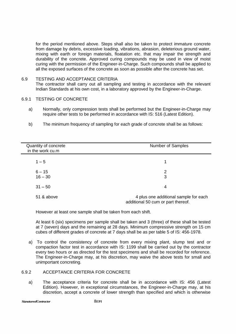
b) The minimum frequency of sampling for each grade of concrete shall be as follows:
Quantity of concrete Number of Samples in the work cu.m
1 – 5 1
6 – 15 2 16 – 30 3 31 – 50 4 51 & above 4 plus one additional sample for each additional 50 cum or part thereof.
However at least one sample shall be taken from each shift.
At least 6 (six) specimens per sample shall be taken and 3 (three) of these shall be tested at 7 (seven) days and the remaining at 28 days. Minimum compressive strength on 15 cm cubes of different grades of concrete at 7 days shall be as per table 5 of IS: 456-1978.
a) To control the consistency of concrete from every mixing plant, slump test and or
compaction factor test in accordance with IS: 1199 shall be carried out by the contractor every two hours or as directed for the test specimens and shall be recorded for reference. The Engineer-in-Charge may, at his discretion, may waive the above tests for small and unimportant concreting.
6.9.2 ACCEPTANCE CRITERIA FOR CONCRETE
a) The acceptance criteria for concrete shall be in accordance with IS: 456 (Latest Edition). However, in exceptional circumstances, the Engineer-in-Charge may, at his discretion, accept a concrete of lower strength than specified and which is otherwise

unacceptable according to IS: 456 (Latest Edition). b) Payment for concrete which is normally unacceptable as per the criteria laid down in
IS: 456, but has been accepted by the Engineer-in-Charge shall be made at a reduced rate prorate to the strength obtained.
c) Concrete work found unsuitable for acceptance shall have to be dismantled and
replacement is to be done as per specification by the contractor. No payment shall be made for the dismantled concrete, the relevant formwork and reinforcement, embedded fixtures, etc. wasted in the dismantled portion. If any damage is done to the embedded portion or adjacent structures, the same shall be made good, free of charge by the contractor, to the satisfaction of the Engineer-in-Charge.
6.9.3 LOAD TEST OF CONCRETE
Load test on concrete, if desired by the Engineer-in-Charge, shall be carried out as soon as possible after expiry of 28 days from the time of placing of concrete as per IS : 456. Entire cost of load testing shall be borne by the contractor and if, any portion of the structure is found unacceptable under the relevant clause of IS: 456, the same shall be dismantled and replaced by a new structure as per specification at no extra cost. If the adjacent structure gets damaged, the same shall be made good free of charge by the contractor to the satisfaction of the Engineer-in-Charge.
7.0 FORMWORK
If it is so desired by the Engineer-in-Charge, the contractor shall prepare before commencement of the actual work, design and drawings for formwork and centering and get them approved by the Engineer-in-Charge. The formwork shall conform to the shape, line and dimensions as shown on the drawings. Formwork shall be of laminated shuttering plywood of minimum 12 mm thickness as per BIS for columns and beams etc. and of laminated shuttering plywood of minimum 12 mm thickness as per BIS and or welded steel plates of uniform pattern for slabs. Struts shall generally be of mild steel tubes and strong sal ballis 150 mm or above in diameter. Bamboos, small diameter ballis, etc., shall not be used unless approved by the Engineer-in-Charge in specific cases. Supports or props should not be put on any un-propped lower suspended floor or beam unless calculations are submitted to the Engineer-in-Charge to confirm the strength of the lower floor beam and no propping shall be taken out until the Engineer-in-Charge’s approval has been obtained.
The centering shall be true and rigid and thoroughly braced both horizontally and diagonally. The forms shall be sufficiently strong to carry without undue deformation, the dead weight load. Where the concrete is vibrated the form work shall be strong enough to withstand the effects of vibration without appreciable deflection, bulging, distortion or loosening of its components. The joints in the form work shall be sufficiently tight to prevent any leakage of mortar. The form work shall be such as to ensure a smooth uniform surface free from honeycombs, air bubbles, bulges, fins and other blemishes. Any blemish or defect found on the notice of the Engineer-in-Charge immediately and rectified free of charge as directed by him. To achieve the desired rigidity tie bolts, spacer blocks,

SignatureofContractor 10EPI
the wires clamps as approved by the Engineer-in-Charge shall be used but they must in no way impair the strength of concrete or leaves stains or marks on the finished surface. Where there are chances of these fixtures being embedded, only mild steel or concrete of adequate strength shall be used. Bolts passing completely through liquid retaining walls/slabs for the purpose of security and aligning the form work should not be used. For exposed interior and exterior concrete surface of beams, columns and walls, plywood or other approved forms thoroughly cleaned and tied together with approved corrosion-resistant device shall be used. All floor and beam centering shall be crowned not less than 8 mm in all direction for every 5.0 meters span. Unless described on the drawing or to the contrary beveled strips 25 mm by 25 mm shall be provided, without any extra charge, to form angles and in corners of column and beam boxes for chamfering of corners. Temporary openings for cleaning, inspection and for pouring concrete shall be provided where they are necessary and as may be directed by the Engineer-in-Charge. The temporary opening shall be so formed that they can be conveniently closed when required and must not leave any mark on the concrete.
7.1 CLEANING AND TREATMENT OF FORMS
All forms shall be thoroughly cleaned of old concrete, wood shaving, saw dust, dirt and dust sticking to them before they are fixed in position. All rubbish loose concrete, chippings, shavings, saw dust etc., shall be scrupulously removed from the interior of the forms before the concrete is poured as directed by the Engineer-in-Charge. Before shuttering is placed in position, the form surface in contact with concrete shall be treated with approved non-staining oil or composition. Care shall be taken that the oil or composition does not come in contact with reinforcing steel or existing concrete surfaces. It shall not be allowed to accumulate at the bottom of the shuttering. The form work shall be so designed and so erected that the forms for slabs and the sides of beams, columns and walls may be removed first, leaving the shuttering to the soffits of beams and their supports in position. Supporting of beams shall not be done except with the approval of the Engineer-in-Charge and props can be reinstated in anticipation of abnormal conditions. If form work for column is erected for the full height of the columns, one side shall be left open and built up in section as placing of concrete proceeds. Wedges, spacer bolts, clamps or other suitable means shall be provided to allow accurate adjustments of the form work and to allow it to be removed gradually without disturbing the concrete.
7.2 REMOVAL OF FORMS
The contractor shall begin the removal of form work only after approval of Engineer-in-Charge. He shall place on record the date on which the concrete is placed in different parts of the work and the date of the removal of form work there from. This record shall be checked and countersigned by the Engineer-in-Charge. The contractor shall be responsible for the safe removal of form work but the Engineer-n-charge may delay the time of removal if he considers it necessary. Any work showing signs of damage through premature removal of form work or loading shall be entirely removal of form work or loading shall be entirely reconstructed without any extra cost to owner. Forms for various types of structural components shall not be removed before the

minimum periods specified in IS: 456 (latest edition) which shall also be subject to the approval of the Engineer-in-Charge. However, in any case, form work shall not be struck until the concrete has reached a strength at least twice the stress to which the concrete may be subjected at the time of removal of forms. The number of props left under, their sizes and disposition shall be such as to be able to safely carry the full dead load of the slab, beam or arch as the case may be together with any live load likely to accrue during or further construction. Where the shape of the element is such that the form work has re-entrant angles, the form work shall be removed as soon as possible after the concrete has set to avoid shrinkage cracks occurring due to the restraint imposed.
The form work shall be so made as to produce a finished concrete, true to shape, lines, levels, plumb and dimensions as shown in drawings.
7.3 RE – USE OF FORMS
Before re – use all forms shall be thoroughly scrapped, cleaned, joints etc., examined and when necessary repaired and inside surface treated as specified herein before. Formwork shall not be used/ re-used if declared unfit or unserviceable by the Engineer-in-Charge.
8.0 FABRICATION AND PLACEMENT OF REINFORCEMENT STEEL
The contractor shall prepare and furnish to EPIL bar-bending schedule with working drawings for all R.C.C. works for review and approval by the Engineer-in-Charge. No work shall be commenced without the approval of the bar-bending schedule by the Engineer-in-Charge. The contractor shall supply, fabricate and place the reinforcement steel to shapes and dimensions as per drawings and specifications. Any adjustment of reinforcement to suit field conditions, construction joints other than those shown on drawings shall be subject to approval of the Engineer-in-Charge.
8.1 CLEANING
Before placing the concrete all steel for reinforcement shall be made free from loose scale, rust, oil, grease, paint or any other harmful matter which may effect its bond with concrete.
8.2 BENDING
Unless otherwise specified, reinforcing steel shall be bent in accordance with procedure specified in IS: 2520 and or as approved by the Engineer-in-Charge. Bends and shapes shall comply strictly with the dimensions given in the approved Bar Bending schedule. Bending schedule shall be rechecked by the contractor before bending and he shall be entirely responsible for its correctness.

SignatureofContractor 12EPI
No reinforcement steel shall be bent when in position in the work without approval of Engineer-in-Charge, whether or not it is partially embedded in concrete. Bars shall not be straightened in manner that will injure the material. Re-bending can only be done if approved by the Engineer-in-Charge. Reinforcement bars shall be bent by machine or other approved means producing a gradual and even motion.
8.3 PLACING IN POSITION
All reinforcement shall be accurately fixed and maintained in position as shown on the drawings by such approved means as steel chairs and or concrete spacer blocks. Bars intended to be in contact at crossing points shall be securely bound together at all such points by two number No. 20G annealed soft iron wire.
Binders shall tightly embrace the bars with which they are intended to be in contact and shall be securely held. The vertical distance between successive layers of bars shall be maintained by provision of steel spacer bars. They should be so spaced that the main bars do not sag perceptively between adjacent spacers. The placing of reinforcement steel shall be completed well in advance of concrete pouring. Immediately before pouring, the reinforcement steel shall be checked by the Engineer-in-Charge for accuracy of placement and cleanliness and necessary corrections as directed by him shall be carried out. The concrete cover over the reinforcement shall be as shown on the approved drawings unless otherwise directed by the Engineer-in-Charge. Care should be taken to ensure that projecting ends of ties and other embedded metal do not encroach into the concrete cover. Where concrete blocks are used for ensuring the cover and positioning reinforcement, they shall be made of mortar 1:2 (one part cement: two parts sand) by volume and cured for at least 7 days. The sizes and locations of the concrete blocks shall be approved by the Engineer-in-Charge. Laps and anchorage lengths of reinforcing bars shall be in accordance with IS:456, unless otherwise specified. If the bars in a lap are not of the same diameter, the smaller will guide the lap length. The laps shall be staggered as far as practicable and as directed by the Engineer-in-Charge, and not more than 50% of bars shall be lapped at particular section.
9.0 BRICK WORK 9.1 SCOPE
This specification covers furnishing, installation, repairing, finishing, curing, protection, maintenance and handing over of masonry works for use in structures and at locations covered under the scope of the contract.
9.2 GENERAL
All masonry work shall be true to lines and levels as shown on drawings. All masonry shall be tightly built against structural members and mounded with dowels, inserts etc., as shown on drawings.
9.3 MORTAR

Mortar for brick work except for half brick or lower thickness walls shall generally be in 1 part cement and 5 parts sand by volume unless otherwise stated. Mortar for half brick and lower thickness brick walls shall be 1 part cement and 4 parts sand by volume unless stated otherwise. The unit of measurement for cement shall be a bag of cement weighing 50 Kg. and this shall be taken as 0.035 cu.m. Other ingredients in specified proportions shall be measured in boxes of suitable size. Sand shall be measured on the basis of its dry volume. In case of damp sand, its quantity shall be increased suitably to allow for bulkage. Cement and sand shall be mixed dry thoroughly on clean approved platform and water shall then be added to obtain a mortar of the consistency of a stiff paste, care being taken to add just sufficient water for the purpose. Mortar shall be used as early as possible after mixing and before it has begun to set and in any case within 30 minutes after water is added to dry mixture. Mortar unused for more than 30 minutes shall be rejected and removed from site of work.
9.4 LAYING
Brick shall be soaked by submergence in clean water for at least 6 hours in approved vats before use. The contractor shall provide tanks of sufficient capacity to allow the specified immersion. Bricks shall be laid in water by hand and not thrown. The bricks shall not be too wet at the time of use, as they are likely to slip on the mortar bed and there will be difficulty in ensuring plumbness of the wall. Bricks shall be laid in English bond unless specified otherwise. Broken bricks shall not be used. Cut bricks shall be used if necessary to complete bond or as closers. Bricks shall be laid with frogs upwards over full mortar beds. Bricks shall be pressed into mortar and tapped into final positions so as to be embed fully in mortar. Inside faces shall be buttered with mortar before the next brick is placed and pressed against it. Thus all joints between bricks shall be fully filled with mortar. Mortar joints shall be kept uniformly 10 mm thick. All joints on face shall be raked to minimum 10 mm depth using raking tool while the mortar is still green to provide bond for plaster or pointing. Where plaster or pointing is not provided, the joints shall be struck flush and finished immediately. Brickwork of two bricks thick or more shall have both faces in true plane. All brickwork shall be built tightly against columns, floor slabs or structural parts, around window and door frames with proper distance to permit caulked joint.
In half brick work 02 Nos. 6 mm dia MS bar to be provided in every 4th course.
9.5 CURING OF MASONRY WORK
Masonry shall be cured by keeping it wet for seven days from the date of laying. In dry weather at the end of days work top surface of masonry shall be kept wet by ponding.
10.0 STONE WORK 10.1 STONE The stone shall be of granite, trap, limestone, sandstone, quartzite etc. and shall be
obtained from quarries approved by Engineer-in-Charge. Stone shall be hard, sound, durable and free from weathering decay and defects like cavities, cracks, flaws, sand holes, injurious veins, patches of loose or soft materials and others similar defects that

SignatureofContractor 14EPI
may adversely affect the strength and appearance. As far as possible stone shall be of uniform colour and texture. Generally stones shall not contain crypst crystalline silica or chart, mica and other deleterious materials like iron –oxide, organic impurities etc.
10.2 SIZE OF STONE Normally stone used should be small enough to be lifted and placed by hand. Unless
otherwise indicated the length of stone shall not exceed 3 times the height and the breadth or base shall not be greater than three-fourth of the thickness of the wall or not less than 15 cm. The height of stone may be upto 30 cm.
10.3 LAYING All stone shall be wetted before use. Each stone shall be placed closed to the stone
already laid so that the thickness of the mortar joints at the face is not more than 20 mm. Face stone shall be arranged suitably to stagger the vertical joints and long vertical joints shall be avoided.
10.4 BOND STONE
At least one bone stone or a set of bond stones shall be provided for every 0.5 sqm of area of wall surface. All the bond stones should be marked suitably with paint as directed by Engineer-in-Charge.
11.0 PLASTER WORK 11.1 SCOPE
This specification covers furnishing, installation, repairing, finishing, curing, testing, protection, maintenance till handing over, of plastering to masonry and concrete. Before commencing work on the finishing items the contractor shall obtain the approval of the Engineer-in-Charge regarding the scheduling of work to minimize damage by other contractors. He shall also undertake normal precautions to prevent damage or disfiguration to work of other contractors and other installations.
11.2 PREPARATION OF SURFACE
All joints in masonry walls be raked out to a depth of at least 10 mm with a hooked tool made for the purpose while the mortar is still green. Walls shall be brushed down with stiff wire brush, to remove all loose dust from the joints and thoroughly washed with water.
For all types of work the base cement concrete slab or masonry surface shall be roughened by chipping and cleaned of all dirt, grease or loose particles by hard brush and water. The surface shall be thoroughly moist to prevent absorption of water from the base course. Any excess of water shall be mopped up. Prior to commencement of actual work, the approval of the Engineer-in-Charge shall be taken as to the acceptability of the base.
11.3 MORTAR
Mortar for plastering shall be as specified in the drawings and in the schedule of finishes.

For sand cement plaster, sand and cement in the specified proportion shall be mixed dry on a water tight platform and minimum water added to achieve working consistency. No mortar which has stood for more than half an hour shall be used, mortar that shows tendency to become dry before this time shall have water added to it.
11.4 INTERNAL WALL PLASTER
This plaster shall be laid in a single coat of 12 mm thickness with cement mortar 1:6 (1 cement : 6 fine sand). The mortar shall be dashed on the prepared surface with a trowel and finished smooth by trowel on the surface. Internal wall plaster shall be carried out on jambs, lintel and sill faces, top and undersides etc., as shown in the drawing or as directed by the Engineer-in-Charge.
11.5 INTERNAL CEILING PLASTER
Ceiling plaster shall be laid in a single coat of 6 mm thickness with cement mortar 1:3 (1 cement : 3 fine sand) applied before wall plaster.
11.6 EXTERNAL PLASTER
Exterior plaster shall be carried out in 2 layers, the first layer being 12 mm thick and the second layer being 6 mm thick. The first layer shall be dashed against the prepared surface with trowel to obtain an even surface. The second layer shall then be applied and finished leaving an even and uniform surface, trowel finished unless otherwise directed by the Engineer-in-Charge.
11.7 APPLICATION OF PLASTER
Plaster when more than 12 mm thick, shall be applied in two coats, i.e., a base coat followed by the finishing coat. Thickness of the base coat, however, shall not exceed 12 mm in thickness. The lower coat shall be thicker than the upper coat. The overall thickness of the coat shall not be less than the minimum thickness shown on the drawings. The under coat shall be allowed to dry and shrink before applying the second coat of plaster. The under coat shall be scratched or roughened before it has fully hardened to form a mechanical key. The method of application shall be ‘thrown on’ rather than ‘applied to trowel’. To ensure even thickness and true surface, patches of plaster about 100 mm to 150 mm square or wooden screed 75 mm wide and of the thickness of the plaster shall be fixed vertically about 2000 mm to 3000 mm apart to act as gauges. The finished wall surface shall be true to plumb, and the contractor shall, without any extra cost to the owner, make up irregularity in the brick work with plaster. All verticals edges of brick pillars, door jambs etc., shall be chamfered or rounded off as directed by the Engineer-in-Charge. All drips, grooves, moldings and cornices as shown on the drawing or instructed by the Engineer-in-Charge shall be done with special care to maintain true lines, levels and profiles. After the plastering work is complete, all debris shall be removed and the area left clean. Any plastering that is damaged shall be repaired and left in good condition at the completion of the job.
12.0 FINISH

SignatureofContractor 16EPI
Where ever any special treatment to the plastered surface is indicated, the work shall be done exactly as shown on the drawings, to the entire satisfaction of the Engineer-in-Charge regarding the texture, colour and finish.
12.1 STANDARD FINISH
Wherever punning is indicated, the interior plaster shall be finished rough. Otherwise the interior plaster shall generally be finished to a smooth surface. The exterior surface shall generally be finished with a wooden float.
12.2 NEAT CEMENT FINISH
Immediately after achieving a true plastered surface with the help of a wooden straight edge, the entire area shall be uniformly treated with a paste of neat cement at the rate of one Kg per sq.m. and rubbed smooth with a trowel.
12.3 CURING
Curing of plaster shall be started as soon as the applied plaster has hardened enough so as not to get damaged. The Engineer-in-Charge will give the decision as to when the plaster has hardened in. Curing shall be done by continuously applying water in a fine spray and shall be carried out at least 7 days. Each individual coat of plaster shall be kept damp continuously for a minimum two days.
12.4 WATER PROOFING ADMIXTURES
The contractor shall use approved water proofing admixtures made of approved manufacturer in the mortar for external plaster work. The quantity to be used etc., shall be in accordance with the manufacturer’s instructions, however, subject to approval of the Engineer-in-Charge. These admixtures shall not contain calcium chloride unless specifically allowed by the Engineer-in-Charge and shall conform to IS : 2645.
12.5 ACCEPTANCE CRITERIA
Finish to masonry and concrete shall fully comply with the drawings, specifications, approved samples and instructions of the Engineer-in-Charge with respect to lines, levels, thickness, colour, texture, pattern and any other special criteria as mentioned in the specification or as shown on the drawing.
13.0 FLOORING 13.1 40 mm thick marble chips flooring rubbed and polished to granolithic finish, under layer 25
mm thick cement concrete 1:2:4 (1 cement : 2 coarse sand : 4 graded stone aggregate 12.5 mm nominal size) and top layer 15 mm thick with white, black, chocolate, grey, yellow or green marble chips of sizes from 1 mm to 4 mm nominal size laid in cement marble powder mix 3:1 (3 cement : 1 marble powder) by weight in proportion of 4:7 (4 cement marble power mix : 7 marble chips) by volume including cement slurry etc complete with medium shade pigment with ordinary cement.

13.2 KOTA STONE FLOORING / SKIRTING a) Material: All the kota stone slab shall be of selected quality, hard, sound, dense and
homogenous in texture free from cracks, decay, weathering and flaws. They shall be hand or machine cut to be requisite thickness. They shall be of the colour indicate in the drawing or as instructed by the Engineer-in-Charge.
The slab shall have the top (exposed) face polished before being bought to site, unless
otherwise specified. The slab shall be conform to the size required. Before starting the work the successful bidder shall get the sample of slabs approved by Engineer-in-Charge.
b) Laying: Mortar of specified mix shall be spread under the area of each slab, roughly to the average
thickness specified in the items. The slab shall be washed clean before laying. It shall be laid on top, pressed, tapped with wooden mallet and brought to the level with the adjoining slabs. It shall be lifted and laid aside. The top surface of the mortar then shall be corrected by adding fresh mortar at hollows. The mortar is allowed to harden a bit and cement slurry of honey like consistency shall be spread over the same at the rate of 4.4Kg of cement per sqm. The edges of the slab already paved shall be buttered with grey cement, with admixture of pigment to match the shade of the slab including polishing and finishing complete.
13.3 NON-SKID CERAMIC TILES
Tiles shall be of 1st quality conforming to IS: 15622, of minimum size 300 mm x 300mm minimum 7 mm thick unless otherwise indicated in the schedule of finishes and drawing. The tile shall be laid over 20 mm thick cement mortar 1:4 over neat cement slurry @ 3kg per sqm over RCC slab including filling joints with neat white cement slurry mixed with pigment to match the color of tiles. The color and shade of the tiles shall be as directed by Eingieer-in-Charge. The tile shall be of approved make.
13.4 GLAZED TILES IN SKIRTING / DADO
The tiles shall be 1st quality conforming to IS: 15622 of minimum thickness of 5 mm and of size as mentioned in the drawing / finishing schedule. The colour shall be got approved by Engineer-in-Charge of EPI. The tile shall be sound, true to shape, flat and free from flaws and other manufacturing defects affecting their utility. The tiles shall be laid over 12 mm thick bed of cement mortar 1:3 (1 cement : 3 coarse sand) and joining with grey cement slurry @ 3.3 kg / sqm including pointing in white cement mixed with pigment of matching shade.
14.0 PROPERTIES, STORAGE AND HANDLING OF COMMON BUILDING MATERIALS 14.1 SCOPE The scope of this section is to specify the properties, storage and handling of common building materials unless otherwise mentioned in the drawings or schedule of items.
SignatureofContractor 18EPI
14.2 GENERAL
The whole of the materials to be mobilized in connection with the permanent work of the contact must be new and of good quality and description of their respective kinds and shall be approved by the Engineer-in-Charge. Except where otherwise specified or permitted by the EPIL, all materials shall conform to the latest edition of the Bureau of Indian Standards. The initials ‘I.S./’BIS’ followed by a number in any of the contract document shall refer to the relevant Indian Standards and current at the date of tendering including all amendments published before that date.
Before ordering materials of any description, the bidders shall submit to the Engineer-in-Charge the names or suppliers proposed and shall obtain approval in writing from the Engineer-in-Charge of the supplier from whom he proposes to obtain such materials. Should the Engineer-in-Charge at any time be not satisfied with the methods of operations carried on at any supplier’s works or place of business, he shall have the power to cancel his previously given consent to obtaining any material from such suppliers.
15.0 WATER PROOFING TREATMENT ON ROOF SLAB 1. The water proofing treatment of roof slabs shall be as given below: a) For flat roof prior to water proof treatment grading of slope 1:80 is to be provided with
screed concrete 1:2:4 (1 cement : 2 coarse sand : 4 graded stone aggregate of 12 mm nominal size) with minimum thickness of 25 mm near rain water drainage pipe.
b) Inaccessible Roof: Providing and laying APP (Atactic Polypropylene Polymer) modified
pre fabricated five layer, 3 mm thick water proofing membrane black finished reinforced with polyester / glass fibre matt. The membrane to be laid over a coat of bitumen primer by using butane torch and finally painted with two coat of aluminum paint of approved make. The laying of the membrane to be done as per the specifications provided by the manufacturer.
Approved Manufacturers: Bitumat Co. Ltd., Pidilite, General Membrane, Tamko, STP
Ltd., Tixsa India Ltd. c) Accessible Roof: Providing and laying APP (Atactic Polypropylene Polymer) five layer, 3
mm thick water proofing membrane black finished reinforced with polyester / glass fibre matt. The membrane to be laid over a coat of bitumen primer by using butane torch and finally overlaid with 40 mm thick concrete screed 1:2:4 (1 cement : 2 coarse sand : 4 graded stone aggregate of 12 mm nominal size). The laying of the membrane to be done as per the specifications provided by the manufacturer.
Approved Manufacturers: Bitumat Co. Ltd., Pidilite, General Membrane, Tamko, STP
Ltd., Tixsa India Ltd.
c) Water proofing treatment for roof slab shall be carried out by an approved specialized firm. Ten years guarantee shall be given by the specialized firm and the contractor on non-judicial stamp paper of Rs. 50.00 (Rupees fifty only) for the effectiveness of water proofing treatment.

16.0 WATER PROOFING TREATMENT ON SUNKEN PORTION
Providing and laying water proofing treatment to vertical and horizontal surfaces of depressed portions of W.C., kitchen and the like consisting of:
i) 1st course of applying cement slurry @ 4.4 Kg/sqm mixed with water proofing
compound ‘Imperno’ of Snowcem or equivalent conforming to IS : 2645 in recommended portions.
ii) 2nd course of 20 mm cement plaster 1:3 (1 cement : 3 coarse sand) mixed with water
proofing compound in recommended proportion. iii) 3rd course of applying blown or residual bitumen applied hot at 1.7 Kg. per sqm of area. iv) 4th course of 400 micron thick PVC sheet. (Overlaps at joint of PVC sheet should be
100 mm wide and pasted to each other with bitumen @ 1.7 Kg/sqm.).
Water proofing treatment for sunken portion shall be carried out by a approved specialized firm. Ten years guarantee shall be given by the specialized firm and the contractor on non-judicial stamp paper of Rs. 50.00 (Rupees fifty only)
17.0 EXPANSION / ISOLATION / SEPARATION JOINTS 17.1 GENERAL
Expansion / Isolation / separation joints in concrete and masonry structure shall be provided at specified places, as per detail indicated in the drawings. The material and types of joints shall be as specified herein after. In case of liquid retaining structures, additional precautions shall be taken to prevent leakage of liquids as may be specified in the drawings or as directed by the Engineer-in-Charge. All materials are to be procured from reliable manufacturers and must have the approval of the Engineer-in-Charge. The Engineer-in-Charge may demand test certificates for the materials and or instruct the contractor to get them tested in an approved laboratory at no extra cost to the owner. Joints shall be formed true to line, level, shape, dimension and quality as per drawings and specifications. Prior approval of the method of forming the joints shall be obtained from the Engineer-in-Charge before starting the work.
17.2 BITUMEN BOARD / EXPANDED POLYSTRENE 17.2.1 BITUMEN BOARD
Bitumen impregnated fibre board of approved manufacturer as per IS : 1838 may be used as filler for expansion joints. It must be durable and waterproof. It shall be compressible and possess a high degree of rebound. The dimensions of the board shall be equal to that of the joints being formed. It shall, preferably be manufactured in one piece, matching the dimensions of the joints and not prepared by cutting to size smaller pieces from larger boards at site.
If required, commercial quality of expanded polystyrene products commonly used for commercial insulations may also be used as filler materials in expansion joints. The thickness may vary from 12 mm to 50 mm. The material shall have to be procured from

SignatureofContractor 20EPI
reliable manufacturers as approved by the Engineer-in-Charge. The method of installation shall be similar to that recommended by the manufacturers. A coat of Bitumen paint may have to be applied on the board against which concrete will be placed.
17.2.2 JOINT SEALING STRIPS
Joint sealing strips may be provided at the construction, expansion and isolation joints as a continuous diaphragm to contain the filler material and or to exclude passage of water or any other material into or out of structure. The sealing strips shall be either metallic like G.I. aluminum or copper, or non-metallic like rubber or PVC.
Sealing strips shall not have any longitudinal joint and shall be procured and installed in largest practicable lengths having a minimum number of transverse joints.
The material is to be procured from reputed manufacturers having proven record of satisfactory supply of joints strips of similar make and shape for other jobs. The jointing procedure shall be as per the manufacturer’s recommendations, revised if necessary by the Engineer-in-Charge. The contractor is to supply all labour and material for testing, protection etc.
17.2.3 METAL SEALING STRIPS
Metal sealing strips shall be either G.I., Aluminum or Copper and formed straight, U shaped, Z shaped or any other shape and of thickness as indicated in the drawings and schedule of finishes and or as instructed by the Engineer-in-Charge.
The transverse joints shall be welded using brass rods and approved fix and shall be tested by method approved by the Engineer-in-Charge to establish that it is leak proof. In case it is found that the joints can not be made leak proof, longer lap lengths and different method of brazing which will render it leak proof, shall be adopted by the contractor without any additional cost to the owner. The edges shall be neatly crimped and bent to ensure proper bond with the concrete.
17.2.4 G.I. STRIPS
G.I. Strips shall be minimum 18 gauge thick and 200 mm in width unless specified otherwise. The standards of galvanizing shall be as per relevant Indian Standard for heavy duty work. The strips shall be strong, durable, without any rust or grease. At the joints the over – lapping shall be for a minimum length of 50 mm.
17.2.5 ALUMINUM STRIPS
Aluminum strips shall be minimum 18 swg thick 300 mm width unless specified otherwise and shall conform to IS : 737 of 19000 grade or 31000 grade (Designation as per IS : 6051). A minimum lap of 50 mm length, if required shall be provided at the joints.
17.2.6 COPPER STRIPS

The copper strips shall be minimum 18 swg in thickness and 300 wide unless specified otherwise and shall conform to relevant Indian Standards. It shall be cleaned thoroughly before use to expose fresh surface, without any reduction in gauge. A minimum lap of 50 mm in length, if required, shall be provided at the joints.
18.0 DAMP PROOF COURSE (DPC)
It shall consists of a layer of cement concrete of proportions 1:2:4 (1 cement : 2 coarse sand : 4 grades stone aggregate of 12 mm nominal size) and of thickness 40 mm.
Cement concrete shall be, admixed with integral water proofing compound in specified proportion as per manufactures instructions. The proportions of water proofing compound shall not exceed 3% by weight of cement. Cement concrete laying shall be thoroughly compacted to dense impervious mass, be cured at least 7 days.
19.0 PLINTH PROTECTION AND DRAIN
It shall be provided around the building as per drawing. 20.0 SYNTHETIC ENAMEL PAINT
Shall be made from synthetic designs and drying oil with rutile titanium dioxide and other selected pigments to give a smooth, hard, durable and glossy finish to all exterior and interior surfaces. The paint shall conform to IS : 2932 and IS : 2933.
21.0 WATER PROOF CEMENT PAINT
Shall be made from good quality white cement and lime resistant colours with accelerators, waterproofing agents and fungicides. The paint shall conform to IS : 5410.
22.0 ACRYLIC EMULSION PAINT
Shall be water based acrylic copolymer emulsion with rutile titanium dioxide and other selected pigments and fungicide. It shall exhibit excellent adhesion to plaster and cement surface and shall resist deterioration by alkali salts. The paint film shall allow the moisture in wall to escape without peeling or blistering. The paint, after it is dried, should be able to withstand washing with mild soap and water without any deterioration in colour or without showing flaking, blistering or peeling.
23.0 OIL BOUND DISTEMPER
Oil bound distemper (IS : 428 -1969) of approved brand and manufacturer shall be used. The primer where used be cement primer or distemper primer. These shall be of same manufacturers as that of distemper. The distemper shall be diluted with prescribed thinner in a manner recommended by the manufacturer. Only sufficient quantity of distemper required for day’s work shall be prepared.
24.0 WHITE WASHING

SignatureofContractor 22EPI
Shall be done from pure shell lime or fat lime, or a mixture of both as instructed by the Engineer-in-Charge, and shall conform to IS : 712 latest edition. Samples of lime shall be submitted to the Engineer-in-Charge for approval and lime as per approved sample shall be brought to site in unslaked condition. After slaking it shall be allowed to remain in a tank of water for two days and then stirred up with a pole until it attains the consistency of thin cream. 100 grams of gum to 6 litres of white wash water and little quantity of indigo of synthetic ultramarine blue shall be added to the lime.
25.0 DOOR, WINDOW AND VENTILATOR 25.1 STEEL DOOR, WINDOW & VENTILATOR Steel door frames shall be manufactured form commercial mild steel sheet of 1.25 mm
thickness conforming to IS: 266 and IS: 435. Hot rolled steel section for fabrication of steel window and ventilator shall conforms to IS: 7452. Shapes, weight and designation of hot rolled sections shall be as per IS: 7452. The workshop for fabrication shall be got approved by Engineer-in-Charge.
Fabrication drawings shall be submitted by the contractor which shall also include the
weights of materials used and got approved from the Engineer-in-Charge. 25.2 GLAZED ALUMINUM DOOR, WINDOWS, FRAMES Work to be executed as per IS – 1948. All sections shall be approved by Engineer-in-
Charge before fabrication is taken up. Doors, Windows, Frames, Mullions, Transoms etc. shall be anodized in bath of sulfuric acid to provide a clear coating of minimum 15 micron (IS: 1968). The anodized materials shall then be sealed by immersing in boiling water for 15 minutes. A protective transparent coating shall be applied to the sections before dispatch from the factory.
Fabrication drawings shall be submitted by the contractor which shall be include the
weights of materials used and got approved from the Engineer-in-Charge. 26.0 GLASS AND GLAZING
The work in general shall consists of supplying and fixing all glass and glazing including all chips, putty, mastic cement etc. wherever required as shown on drawings.
The contractor shall supply and install all glass and glazing as required for various doors, windows, sashes, ventilators and fixed louvers, miscellaneous glazing having uniform refractive index and free from flaws, specks and bubbles. The glass be brought to site in the original packing from the manufacturer and cut to size at site. The cut edges shall be straight free from chips, spalls or any other damages. Clear glass shall be flat drawn sheet glass and shall be at least 4 mm thick. Sheet glass for doors shall be minimum 6.3 mm thick.
Wired glass shall be thick rolled glass with centrally embedded 24 g. wire mesh of Georgian type. This may be of clear or coloured glass, as shown in drawings.
Quick setting putty shall be used for windows and sashes except when glare reducing glass is used where it shall be of non-setting type of approved make conforming to IS : 419.
Neoprene gaskets with snap-fit glazing shall be fixed as per manufacture’s instructions and shall fit firmly against the glass to give a leak-proof installation.

27.0 CARPENTRY AND JOINERY
This shall include supply and fixing of door and window shutters, paneled and flush doors, partitions, wall paneling, shelves, furniture, cabinets, pelmets etc., as shown in drawings including a prime coat of approved paint, varnish/synthetic enamel paint or fixing of plastic laminate where called for in the schedule. This shall also include supply and fixing of all hardware and fittings shown in the drawings.
27.2 TIMBER
Unless otherwise specified all timber shall be best quality well seasoned second class hard wood free from larger loose knots, cracks, and other defects. Where specified timber shall be treated with approved wood preservative. Before starting the carpentry work, the contractor shall have the wood approved by the Engineer-in-Charge.
27.3 PLYWOOD
Plywood shall be commercial quality or with decorative surface veneer. Unless otherwise stated, the adhesive used in plywood shall be phenol formaldehyde resin of B.W.R. grade conforming to IS: 848.
27.4 FLUSH DOORS
Flush doors shall be block or solid core doors with commercial or decorative faces and hardwood edges. The core for solid core doors shall be of block board or wood particle board. The thickness shall be as specified in the ‘Schedule finishes’. Flush doors and board shall be of the required size and thickness. Flush doors shall be ordered to a size little more in which to that after trimming, it fits the opening between rebates perfectly. Where shown in the drawings and the schedule, flush doors shall be surfaced with decorative laminates of required type and design. The laminate shall be glued to the panel with liquid synthetic phenol formaldehyde resin glue and kept in suitably pressed for at least 12 hours as per best trade practice.
27.5 PANELED AND GLAZED DOORS AND WINDOW SHUTTERS
The wood shall be accurately cut, planed and smoothened to hold full dimensions as shown in the drawings after finishing. The thickness of stiles and rails shall be as required for the shutters. Stiles and rails shall be properly and accurately mortised and tounged. While assembling a leaf, stiles shall be left projecting as a horn. The stiles and rails shall have 12 mm groove or as specified in the drawings for the panel or glass to fit in.
27.6 FLY PROOF SHUTTER The wood shall be accurately cut, planed and smoothened to hold full dimensions as
shown in the drawings after finishing. The thickness of stiles and rails shall be as required for the shutters. Patching or plugging of any kind shall not be permitted except as provided. The stiles and rails shall be given a rebate to receive the wire gauge which shall from the panels.
24 gauge MS, wire Gauze conforming to IS: 1568 shall be used for fly proof shutter. 27.7 CABINET WORK

SignatureofContractor 24EPI
All cabinet work shall be a prime cost item. Cabinets shall be prepared at site as per best practices and techniques, machines, tools and craftsmen available in the furniture making industry. Sample of the work shall be approved by the Engineer-in-Charge.
Details shall be incorporated as shown in the drawings. Bottom shall be framed in to the drawer front, sides and back. Accurately aligned guides and proper clearance smoothly without bending. All joints and all work shall be glued together with phenol formaldehyde synthetic glue resin, the parts being clamped and pressed at least for 12 hours.
28.0 FITTINGS AND FIXTURES
Fixtures and fittings for doors, windows etc., shall be as shown on drawing and finishing schedule. These shall be heavy type, good quality and from approved manufacturer.
28.1 WORKMANSHIP 28.1.1 GENERAL
The work shall be done by skilled carpenters as per details shown on drawing or instructed by the Engineer-in-Charge. Farming timber and other work shall be close fitting with proper wood joinery, accurately set to required lines or levels and rigidly secured in place. The surface of frames etc., which will come in contact with masonry after fixing, shall be given two coats of approved paint before fixing. Mastic caulking shall be done after fixing external door and window frames. Special care shall be taken to match the grain of timber or plywood which will be subsequently polished. Screwing or nailing will not be permitted to the edge of plywood or chip board sheets. All exposed plywood edges shall be finished with teakwood lipping unless otherwise shown on drawings.
28.1.2 FINISH
All carpentry work after finishing shall be sand papered smooth. A prime coat of paint shall be given after inspection by the Engineer-in-Charge to all surfaces other than those which shall be subsequently polished or covered with laminated plastic sheet.
29.0 The successful bidder shall establish a field testing laboratory at site, equipped with the
minimum following equipments. 1. One no. compression testing machine of 100 tonne capacity suitable for testing
concrete cube of 150 mm x 150 mm x 150 mm size. 2. One no. electronic weighing machine with maximum weight of 10 kg. 3. 24 nos. MS cube moulds of size 150 mm x 150 mm x 150 mm. 4. One no. slump cone. 5. One set of sieves for fine aggregate. (includes sieves of designation 4.75 mm, 2.36
mm, 1.18 mm, 600 microns, 300 microns, 150 microns). 6. One set of sieves for coarse aggregate. (includes sieves of designation 37.5 mm,
19 mm, 9.5 mm, 4.75 mm). 7. One no. silt testing jar. 8. One no. electric oven. 9. One no. vernier calliper. 10. One no. screw gauge.

30.0 LIST OF APPROVED VENDORS/MAKES
S.NO DESCRIPTION OF ITEMS APPROVED MAKES
1. FLOAT GLASS MODI GUARD, ST. GOBAIN (FRANCE) ASHAHI , GUARDIAN (U.S.A),ATUL.
2. ALUMINIUM EXTRUSIONS HINDALCO, INDALCO, JINDAL
3 STAINLESS STEEL SALEM STEEL, INDALCO, JINDAL
4 EPDM AMEE OR AS APPROVED BY EIC
5 EXPANSION ANCHORS/FASTNERS HILTI, FISHERS SS 316 (WITH STAINLESS STEEL BOLTS NUTS AND WASHERS)
6 NUTS & BOLTS HILTI, FISHER, , GKW, AVON, ARMOUR
7 VITRIFIED TILES KAJARIA, NITCO,ORIENT,SOMANY
8 PAINTS ASIAN PAINTS, NEROLEC, BERGER.
9 CEMENT ( ORDINARY PORTLAND/ PORTLAND POZZOLANA )
ACC/ ULTRATECH / LAFARGE/ CROWN/ DALMIA
10 WATER PROOFING COMPOUND CHOCKSEY CHEMICAL, IMPERNO, CICO, ACCO PROOF, FOSROC, ROFFE, SCOT,IMPERMO,PIDILITE
11 APP (atactic Polypropylene Polymer) Membrane
PIDILITE INDUSTRIES LTD. TEXSA INDIA LITD., STP LTD., BITUMAT CO. LTD., GENERAL MEMBRANE.
12 REINF./STRUCTURAL STEEL SAIL/TATA/RINL/JINDAL
13 EPOXY PAINT CHOCKESY CHEMICAL (PVT.) LTD., DR. BECK, ASIAN APINTS, GARWARE PAINTS
14 POLYSULPHIDE/POLYURETHENE SEALANT
MBT, CHOKSEY
15 CONCRETE ADDITIVE FOSROC, STP, CICO-TL
16 CHEQUERED TILES NITCO, BASANT BETONS, BEZELAL
17 INSULATION TWIGA, ROCKWOOL
18 CHEMICAL WATER PROOFING CHOCKSEY CHEMICAL, FOSROC
19 ZINC CHROMATIC PRIMER SHALIMAR, ASIAM PAINTS, GARWARE
20 CHEMICAL/ MECHANICAL ANCHOR FASTNERS
HILTI, FISCHER.DASH
21 SUNKEN PORTION TREATMENT CHOSKEY, ROFEE, CICO, SIKA, PIDLITE
22 DOOR CLOSER / FLOOR SPRING DOOR KING, EVERITE, HARDWYN
23 UPVC PIPES & FITTINGS PRINCE/SUPREME/CALCUTTA PIPES/ ISI
MARKED

SignatureofContractor 26EPI
REMARKS :
1) The materials of first quality of the above approved makes are to be used. 2) The material samples shall be got tested by Engineer-in-Charge as per provisions of
tender documents for which all costs shall be borne by the contractor. 31.0 I.S. CODE Some of the important relevant applicable IS codes are mentioned below:
IS: 1200 (Pertaining to respective work): Method of measurement of building and Civil
Engineering works. IS: 456 Code of practice for plain and reinforced concrete. IS: 1199 Method of sampling and analysis of concrete. IS: 1838 Preformed fillers for expansion joints in concrete non extruding and resilient type
(Bitumen impregnate filler) IS: 2386 (Part I to IV) Methods of tests for aggregates for concrete. IS: 2505 General requirements for concrete vibrators, immersion type. IS: 2506 Screed board concrete vibrators. IS: 2514 Concrete vibrating tables. IS: 3025 Code of practice for concrete structure for the storage of liquids. IS: 3350 Methods of tests for routine control for water used in industry. IS: 4565 From vibrators for concrete. IS: 9130 Admixture for concrete. IS: 516 Method of tests for strength of concrete. IS: 1786 High strength deformed bars for concrete reinforcement. IS: 1081 Code of practice for fixing and glazing of metal doors, windows and ventilators. IS: 2502 Code of practice of bending and fixing bars for concrete reinforcement. IS: 2571 Code of practice for welding and mild steel bars used for reinforced concrete
construction. IS: 2202 Specification for wooden flush door shutter. IS: 1661 Code of practice for cement and cement lime plaster finish on walls and ceilings.

IS: 4101 Code of practice for external facing and veneers. IS: 6248 Metal rolling shutter and rolling grills. IS: 3548 Code of practice for glazing in building. IS: 1081 Code of practice for fixing and glazing metal doors, windows and ventilators. IS: 1038 Specifications for steel doors, windows and ventilators.

SignatureofContractor 28EPI
SPECIFICATION FOR ELECTRICAL WORKS
TECHNICAL SPECIFICATIONS
FOR INTERNAL ELECTRICAL WORK
1.0 WIRING:
1.1 Scope:
1.1.1 The scope of this section covers the supply, erection, testing and commissioning of
conduits & wiring for lighting and power. Wiring shall be carried out in accordance
with relevant I.S. rules and regulations.
1.2 System of wiring:
1.2.1 All lights and power wiring shall be carried out in surface conduits or recess wiring in
conduits or floor ducts as specified.
1.2.2 I.E.E. regulations shall be applicable for all material and workmanship.

1.2.3 The wiring to be carried out in such a manner that specified 'Power' wiring shall be kept
separate and distinct from 'Lighting' wiring. The wiring shall be done on the
distribution system with main and branch distribution boards at convenient physical and
electrical centers as shown in drawings. All conductors shall be run as far as possible
along the walls and ceiling and above false ceiling so as it can be easily accessible and
capable of being thoroughly inspected. In all types of wiring, due consideration shall be
given for neatness and good appearance.
1.2.4 The balancing of load in three wire or poly phases installations shall be arranged before
hand to the satisfaction of Engineer-in-charge. In large or important areas, light and
socket outlet points shall be distributed over more than one circuit as directed.
1.2.5 Medium pressure wiring and associated apparatus shall comply in all respects with the
requirements of IEE rules.
1.2.6 No wiring shall be carried out until the appropriate tests required in Section “Inspection
and Testing" have been done and the Engineer-in-Charge has given his clearance for
wiring to commence.
1.2.7 At expansion joints, adequate slack shall be left in the cables.
1.2.8 Where conduits are installed for wiring by others, a draw wire shall be provided
between each draw-in position.
1.2.9 Cables forming part of communication circuits shall have identification sleeves at their
terminations. Identification shall be consistent with the relevant wiring diagrams.
1.3 Joints & Looping Back:
1.3.1 The wiring shall be done in a 'looping System'. Phase or live conductors shall be looped
at the switch box and neutral conductor can be looped either from the light, fan or
socket outlet.
1.3.2 No bare or twist joints shall be made at intermediate points in the through run of cables,
unless the length of final sub circuit or sub-main or main is more than the length of the
standard coil given by the manufacturer of the cable.
1.3.3 Termination of multistrand conductors shall be done using suitable crimpling type
thimbles.
1.4 PVC CONDUIT AND CONDUIT ACCESSORIES:-
1.4.1 All non-metallic conduit pipes and accessories shall be of suitable material complying
with IS:2509-1973 and IS:3419-1976 for rigid conduits and IS:6946-1973 for
flexible conduits. The interior of the conduits shall be free from obstructions. The rigid
conduit pipes shall be ISI marked.

SignatureofContractor 30EPI
1.4.2 The conduits shall be circular in cross-section. The conduits shall be designated by
their nominal outside diameter. The dimensional details of rigid non-metallic conduits
are given in Table-III.
1.4.3 No non-metallic conduit less than 20 mm in diameter shall be used.
1.4.4 The conduit wiring system shall be complete in all respect including accessories.
1.4.5 Rigid conduit accessories shall be normally of grip type.
1.4.6 Flexible conduit accessories shall be of threaded type.
1.4.7 Bends, couplers etc. shall be solid type in recessed type of works, and may be solid or
inspection type as required, in surface type of works.
1.4.8 Saddles for fixing conduits shall be heavy gauge non-metallic type with base.
1.4.9 The maximum number of PVC insulated cables conforming to IS: 694-1990 that can be
drawn in one conduit is given size wise in Table-1. And the number of cables per
conduit shall be exceeded. Conduit sizes shall be selected accordingly in each run.
1.4.10 The erection of conduits of each sections shall be completed before the cables are
drawn in.
1.5 Installation-Common aspects for both recessed and surface conduit works:-
1.5.1 Conduit Joints
(i) All joints shall be sealed/cemented with approved cement. Damaged conduit pipes/
fittings shall not be used in the work. Cut ends of conduit pipes shall have no sharp
edges nor any burrs left to avoid damage to the insulation of conductors while pulling
them through such pipes.
(ii) The Engineer-in-charge, with a view to ensuring that the above provision has been
carried out, may require that the separate lengths of conduit etc. after they have been
prepared, shall be submitted for inspection before being fixed.
1.5.2 Bends in Conduit
(i) All bends in the system may be formed either by bending the pipes by an approved
method of heating, or by inserting suitable accessories such as bends, elbows or
similar fittings, or by fixing non-metallic inspection boxes, whichever is most
suitable. Where necessary, solid type fittings shall be used.
(ii) Radius of bends in conduit pipes shall not be less than 7.5 cm. No length of conduit
shall have more than the equivalent of four quarter bends from outlet to out-let.
(iii) Care shall be taken while bending the pipes to ensure that the conduit pipe is not
injured, and that the internal diameter is not effectively reduced.
1.6 Installation-Additional requirements for surface conduit work
(i) Conduit pipes shall be fixed by heavy gauge non-metallic saddles with base, secured to
suitable approved plugs with screws in an approved manner, at an interval of not more
than 60 cm, but on either side of couplers or bends or similar fittings, saddles shall be
fixed at a closer distance from the centre of such fittings. Slotted PVC saddles may
also be used where the PVC pipe can be pushed in through the slots. The minimum
width and thickness of the ordinary clips or the girder clips for different sizes of

conduits shall be as given in Table-II.
(ii) Where the conduit pipes are to be laid along the trusses, steel joists etc. the same shall
be secured by means of saddles or girder clips as required by the Engineer-in-charge.
Where it is not possible to use these for fixing, suitable clamps with bolts and nuts shall
be used.
(iii) If the conduit pipes are liable to mechanical damage, they shall be adequately protected.
1.7 Installation-Additional requirements for recessed conduit work
1.7.1 Make Chase
(i) The chase in the wall shall be neatly made, and of ample dimensions to permit the
conduit to be fixed in the manner desired.
(ii) In the case of buildings under construction, the conduits shall be buried in the wall
before plastering, and shall be finished neatly after erection of conduit.
(iii) In case of exposed brick / rubble masonry work, special care shall be taken to fix the
conduit and accessories in position along with the building work.
1.7.2 Fixing Conduit in Chase
(i) The conduit pipe shall be fixed by means of staples, or by means of non-metallic
saddles, placed at not more than 60 cm apart, or shall be fixed by any other approved
means of fixing.
(ii) At either side of the bends, saddles/staples shall be fixed at a distance of 15 cm from the
centre of the bends.
1.7.3 Erection in RCC work
(i) The conduit pipes shall be shall be laid in position and fixed to the steel reinforcement
bars by steel binding wires before the concerting is done. The conduit pipes shall be
fixed firmly to the steel reinforcement bars to avoid their dislocation during pouring of
cement concrete and subsequent taming of the same.
(ii) Fixing of standard bends or elbows shall be avoided as far as practicable, and all curves
shall be maintained by bending the conduit pipe itself with a long radius which will
permit easy drawing in of conductors.
(iii) Location of inspection/ junction boxes in RCC work should be identified by suitable
means to avoid unnecessary chipping of the RCC slab subsequently to locate these
boxes.
1.7.4 Fixing of Inspection Boxes
(i) Suitable inspection boxes to the minimum requirement shall be provided to permit
inspection, and to facilitate replacement of wires, if necessary.
(ii) These shall be mounted flush with the wall or ceiling concrete. Minimum 65 mm depth
junction boxes shall be used in roof slabs and the depth of the boxes in other places
shall be per IS: 2667-1977.
(iii) Suitable ventilating holes shall be provided in the inspection box covers if directed.

SignatureofContractor 32EPI
1.8 Routes And Segregation:
1.8.1 In case the routes of conduit and ducting are not shown on the drawings, they shall be
determined by the Contractor and approved by Engineer-in-Charge before work is
started. This requirement shall apply where the conduit or duct is concealed within the
building fabric as well as where they are on the surface.
1.8.2 Conduit and ducting shall be parallel with lines of building construction and properly
aligned except where conduit is permitted in floor screeds. Conduit buried in wall
finishes shall run vertically only, unless Engineer-in-Charge gives approval to deviate
from this requirement.
1.8.3 A minimum clearance of 150 mm between conduits shall be allowed from any
equipment/ Low current services conduit like Telephone/Computer/CCTV/ pipe work
or duct work. Distance shall be measured from the external surface of any lagging. In
event of difficulty in achieving this requirement, Engineer-in-Charge shall be informed.
1.9 Wires:
1.9.1 The type and size of wires shall be as indicated in the BOQ / Drawings. All the
material supplied and used by the contractor shall be new. Wires shall have copper
conductors unless otherwise specified, and the size shall be as per IS standards unless
specified.
1.9.2 All wires shall comply with relevant IS. Type of wire to be used shall be as specified in
the BOQ / Drawings.
1.9.3 The colour identification of wires shall comply with the IEE wiring regulations for all
category of circuits. Core identification colours shall extend throughout the length of
PVC insulated wires. Core identification for sound distribution or public address
systems shall be in grey colour.
1.9.4 Wires shall be protected throughout their length by trunking, ducting, conduit and
equipment enclosures. Framework or partitions may be used, but only where indicated
or with the approval of Engineer-in-Charge.
1.9.5 Wires carrying direct current may, if desired, be bunched whatever their polarity, but
wires carrying alternating current, if installed in metal conduit shall always be bunched
so that the out going and return wires are drawn into the same conduit.
1.9.6 Where the distribution is for single phase loads only, conductors for these phases shall
be drawn in one conduit.
1.9.7 In case of three phase loads, separate conduits for separate phase shall be run from the
distribution boards to the load points, or outlets as the case may be.
1.9.8 Wires shall comply with relevant IS for LV & ELV circuits.
1.9.9 Where conduits cross expansion and settlement joints in the building structure, suitable
provision shall be made to allow for movement of the structure. The Contractor shall
submit his proposals for the approval of the Engineer-in-Charge.
1.9.10 Conduits entering voids shall terminate not less than 22 mm clear of the building fabric.

Open ends of conduit shall be temporarily plugged immediately after they are installed
to prevent ingress of water and solid materials.
1.9.11 Where wires pass through joints, the number and size of holes shall allow for easy
withdrawal and replacement of cables. The diameter of holes shall not exceed 1/6th the
depth of the joints. They shall be approximately on the centre line and shall be not less
than 75 mm between centres. Joints shall not be notched.
1.9.12 The method to be used for forming fire barriers at fire resistant structural elements such
as floors and walls shall be submitted for the Engineer-in-Charge's approval.
1.9.13 Where wires enter a metal enclosure, they shall be protected by grommets or secured by
wires clamps.
1.9.14 Wires shall be looped between outlet points and as far as practicable, intermediate
joints shall not be used.
1.9.15 Wires fixed to the surface, except in ducts, shall be protected up to a height of 1500 mm
by high impact PVC channel.
1.9.16 Wires shall have identification sleeves at their terminations.
1.9.17 Identification shall be consistent with the relevant wiring diagrams.
1.10 Switches:
1.10.1 Switches shall be single pole unless otherwise indicated. Their current ratings shall be
as indicated, allowance being made for any inductive or capacitive load.
1.10.2 Wall mounted switches located inside buildings shall have rocker type actuating
members unless otherwise indicated. Where mounted adjacent to one another, they
shall be grouped in a multi gang box with a common front plate.
1.10.3 Pull cord operated switches shall be fixed to white moulded plastic mounting blocks,
which in turn shall be fixed to a circular conduit box. Where the conduit boxes are flush
with the finish, mounting block shall overlap them. Pull cords shall be white or natural
colour and the lower end shall terminate in a moulding of rubber or plastic material.
1.11 Socket Outlets:
1.11.1 Socket outlets shall be of type and rating as indicated. Pilot contacts shall be provided
where indicated.
1.11.2 Socket outlets shall be switched where indicated. On socket outlets rated at 16A and
located inside buildings, the switches shall be single pole and have rocker type
actuating members unless otherwise indicated.
1.11.3 Socket outlets for wet locations shall be provided with covers, which shall be screwed
on. Any cover required to achieve total enclosure and to ensure the required degree of
protection against moisture shall be securely fixed to socket outlet.
1.11.4 Sockets/ Telephone/ Computer/ CCTV/ Socket outlets shall be of the type as mentioned
in the BOQ.

SignatureofContractor 34EPI
1.12 Plugs:
1.12.1 ISI marked Plugs shall be provided as indicated. Plug bodies shall be of metal, plastic
or other material as indicated.
1.12.2 Plugs rated at 16A shall be of a non-resilient material unless otherwise indicated.
1.13 Terminal Blocks:
1.13.1 Conductors shall be clamped between metal surface and no screws shall make direct
contact with conductors.
1.13.2 The design shall be such as to maintain sufficient contact pressure to ensure
connections on negligible impedance at all times.
1.13.3 Metal in contact with conductors shall be 85% copper alloy and any screws shall be of
metal that is electrolytic ally compatible with the copper alloy. The moulded housing
shall be an insulating material suitable for the maximum operating temperature of the
conductor.
1.14 Mounting Heights:
1.14.1 Mounting heights shall be as follows unless otherwise indicated in the drawings, where
decision shall be obtained by contractor before start of work.
MOUNTING HEIGHTS (for accessories and equipment)
1. Bracket Light 2250mm
2. Mirror light 1800mm
3. Switch board 1050mm
4. 5/15A light/power sockets 625mm
5. 5/15A switch for sockets 625mm
6. D Bs 1500mm
7. 15A socket in toilet 1800mm
8. 15A switch in toilet 1050mm
9. 15/5A power points in Pantry 150mm above cooking slab
10. Computer/Telephone outlet. 625mm
NOTES:
1. Heights are from finished floor level to the center of the accessory or equipment, except in
the case of worktops when the measurement shall be from the worktop surface.
2. If the specified height of an accessory coincides with the top of tiling, the accessory shall be
mounted above the tiling, leaving a clear gap of 50 mm.
3. Where apparatus is located underneath a worktop, the accessory shall be mounted 100 mm
below the underside of the worktop.
1.14.2 Where difficulty in locating accessories or equipment occurs the Engineer-in-Charge
shall be informed.
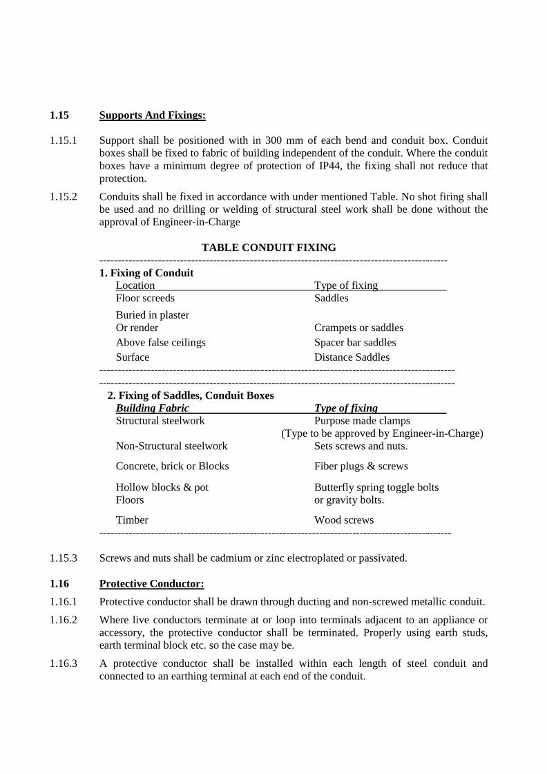
1.15 Supports And Fixings:
1.15.1 Support shall be positioned with in 300 mm of each bend and conduit box. Conduit
boxes shall be fixed to fabric of building independent of the conduit. Where the conduit
boxes have a minimum degree of protection of IP44, the fixing shall not reduce that
protection.
1.15.2 Conduits shall be fixed in accordance with under mentioned Table. No shot firing shall
be used and no drilling or welding of structural steel work shall be done without the
approval of Engineer-in-Charge
TABLE CONDUIT FIXING
-----------------------------------------------------------------------------------------------
1. Fixing of Conduit
Location Type of fixing
Floor screeds Saddles
Buried in plaster
Or render Crampets or saddles
Above false ceilings Spacer bar saddles
Surface Distance Saddles
-------------------------------------------------------------------------------------------------
-------------------------------------------------------------------------------------------------
2. Fixing of Saddles, Conduit Boxes
Building Fabric Type of fixing
Structural steelwork Purpose made clamps
(Type to be approved by Engineer-in-Charge)
Non-Structural steelwork Sets screws and nuts.
Concrete, brick or Blocks Fiber plugs & screws
Hollow blocks & pot Butterfly spring toggle bolts
Floors or gravity bolts.
Timber Wood screws
------------------------------------------------------------------------------------------------
1.15.3 Screws and nuts shall be cadmium or zinc electroplated or passivated.
1.16 Protective Conductor:
1.16.1 Protective conductor shall be drawn through ducting and non-screwed metallic conduit.
1.16.2 Where live conductors terminate at or loop into terminals adjacent to an appliance or
accessory, the protective conductor shall be terminated. Properly using earth studs,
earth terminal block etc. so the case may be.
1.16.3 A protective conductor shall be installed within each length of steel conduit and
connected to an earthing terminal at each end of the conduit.

SignatureofContractor 36EPI
1.17 Outlet Boxes
1.17.1 16 SWG MS/G.I. boxes of the required sizes shall be provided to house the
Switch/sockets/Telephone/TV/Computer outlets as may be required/ mentioned in
BOQ. These shall be so designed that there is ample space at the rear and at the sides to
accommodate conductors at the conduit entries. These shall be completely concealed
leaving edges flush with wall surface unless mentioned otherwise.
1.18 Draw Boxes/ Inspection Boxes
1.18.1 16 SWG Mild Steel/GI draw/inspection boxes of adequate dimensions minimum size
75 mm x 75 mm shall be provided at convenient points on walls to faciliate long runs of
conductors. They will be completely concealed with 3 mm Perspex/ hylam covers flush
with plate work. These boxes will, as far as possible, be located where found suitable
by the Engineer-in-Charge.
1.19 Protection Of Conduits
1.19.1 To safeguard against filling up with plaster etc. all the outlet and switch boxes will be
provided with temporary covers and plugs within the tendered cost which shall be
replaced by sheet / plate covers as required. All screwed and socketed joints shall be
made fully water tight by the use of white lead for steel conduits.
1.20 Cleaning of Conduit Runs
1.20.1 The entire conduit system including outlets and boxes shall be thoroughly cleaned after
completion of erection and before drawing in of cables.
1.21 Laying Of Dummy Conduit
1.21.1 The dummy conduits shall be the same as conduits for Electrical work and as specified
before. The minimum size shall be 20 mm dia. Junction boxes shall be provided at
distance not exceeding 10 m. The Contractor must make such modifications as the
system designer / manufacturer desires in consultation with the Owners / Architects.
These conduits shall be provided with steel draw boxes of at least 14 SWG.
1.22 Fish Wires
1.22.1 To facilitate drawing of wiring through conduits/ G.I / Steel pipes etc., G.I. fish wire of
14 SWG, wherever needed, shall be provided along with recessed conduit / pipes,
without any extra cost.

Table –I
Maximum number of PVC insulated 650/1100 V Grade Aluminium/Copper
conductor cable conforming to IS:694/1990
Nominal Cross sectional area of cond. in sq. mm
20mm 25mm 32mm 38mm 51mm 64mm
S B S B S B S B S B S B
1 2 3 4 5 6 7 8 9 10 11 12 13
1.5 5 4 10 8 18 12 - - - - - -
2.5 5 3 8 6 12 10 - - - - - -
4 3 2 6 5 10 8 - - - - - -
6 2 - 5 4 8 7 - - - - - -
10 2 - 4 3 6 5 8 6 - - - -
16 - - 2 2 3 3 6 5 10 7 12 8
25 - - - - 3 2 5 3 8 6 9 7
35 - - - - - - 3 2 6 5 8 6
50 - - - - - - - - 5 3 6 5
70 - - - - - - - - 4 3 5 4
NOTE:-
1. The above table shows the maximum capacity of conduits for a simultaneous drawing in of
cable.
2. The columns headed ‘S’ apply to runs of conduits which have distance not exceeding 4.25 m
between draw in boxes and which do not deflect from the straight by an angle of more than 15
degrees. The columns headed ‘B’ apply to runs of conduit which deflect from The straight by an
able of more than 15 degrees.
3. Conduit sizes are the nominal external diameters.
TABLE-II Girder Clips or Clamps
S.NO. Size of conduit Width Thickness
1 20 mm 19mm 0.9mm (20 SWG)

SignatureofContractor 38EPI
TABLE-III
Dimensional details of rigid non-metallic conduits. (All dimensions in mm)
---------------------------------------------------------------------------------------------------
S.No. Nominal Maximum Minimum Maximum Maximum
Outside outside- inside- permissible permissible
Diameter diameter diameter eccentricity quality
(in mm.) (in mm.) (in mm.) (in mm.) (in mm.)
----------------------------------------------------------------------------------------------------
1. 20 20+0.3 17.2 0.2 0.5
2. 25 25+0.3 21.6 0.2 0.5
3. 32 32+0.3 28.2 0.2 0.5
4. 40 40+0.3 35.8 0.2 0.5
5. 50 50+0.3 45.0 0.4 0.6 ------------------------------------------------------------------------------------------------------------------------
----
2 25 mm 19mm 0.9mm (20 SWG)
3 32 mm & above 25mm 1.2mm (18 SWG)

2.0 MCB DISTRIBUTION BOARDS: 2.1 Scope:
2.1.1 The scope of this section covers Supply, installation, testing and commissioning of
Miniature circuit breaker boards and Miniature Circuit breakers. Miniature circuit
breaker boards shall comply with BS 5486 part 12 a clause 3.2 and 3.3. They shall have
a fault withstand classification of class 1 unless otherwise indicated.
2.2 MCB Distribution Boards
2.2.1 These distribution boards shall be used for control of all lighting/power circuits and shall
consist of single pole/ single/ double/TP & N/ triple/four pole miniature circuit breakers
mounted in double cover design, dust tight, heavy gauge sheet steel enclosures preferably
zinc coated with powder coating finish.
2.2.2 Distribution Boards shall be flush or surface pattern according to the requirements of their
location and shall incorporate isolators/MCB and circuit switches as specified in bill of
quantities.
2.2.3 All MCBs shall be connected to the electrolytic copper busbars with direct bolted
connections.
2.2.4 Earthing bar and neutral bars shall be provided having sufficient ways to enable each cable
to be connected to a separate terminal. Neutral connections shall be corresponding in
position to phase connections.
2.2.5 Distribution boards shall have phase barriers and PVC ducts for all interior wiring. All
distribution boards shall have removable end plates at top and bottom and handles with
provision for locking.
2.2.6 Phase barriers shall be provided in the 3-phase distribution Boards.
2.2.7 In TP&N distribution boards, neutral busbars shall have one outgoing terminal for each
outgoing circuit.
2.2.8 Size of SDB shall be selected to cater to extra space on the bus for mounting ELCBs in
addition to number of outgoing MCBs specified in the BOQ / Drawings.
2.2.9 A multi-terminal bar for the circuit protective conductors shall be provided for both
insulated and metal cased boards, with one terminal for each outgoing circuit. It shall be
directly connected to the earthing terminal without dependence on the exposed conductive
parts of the enclosure.
2.2.10 Identification of each MCB way shall be by numbering. Identification in the neutral busbar
and protective conductor bar shall clearly relate each terminal to its respective MCB way.
2.2.11 Spare MCB ways shall be provided as indicated in BOQ / Drawings. Where specific ratings
are indicated, MCB shall be incorporated otherwise the ways shall be left blank but suitable
for future additions. Suitable number of blanking plates shall be fixed in the DB if the
space for MCB is left blank.

SignatureofContractor 40EPI
2.2.12 A separate Junction box of min. height of 150 mm shall be provided for extra lengths of
outgoing circuit wires on Top/Bottom (as required) to avoid jumbling of wires within the
main section of SDB. The junction box will be properly earthed along with the SDB.
2.3 Miniature Circuit Breakers
2.3.1 Miniature circuit breakers shall be designed and tested strictly in accordance with the
relevant parts of Indian standards and shall consist of spring accelerated quick-make
and quick break action mechanism fitted in moulded cases of high di-electric strength
plastic or urea. Fixed and moving contacts shall have silver tungsten contacts.
2.3.2 Miniature circuit breakers used shall be of “B” Series for Normal lighting circuits and
Normal Power/Geyser Loads. For AC loads, Tungsten lamps fittings, Sodium/Mercury
Discharge lamps “C” Series shall be used unless otherwise mentioned.
2.3.3 Miniature circuit breakers shall have a minimum breaking capacity of 10 KA at 415 V.
2.4 ELCBs
2.4.1 ELCBs shall be designed and tested strictly in accordance with the relevant parts of
Indian standards. Fixed and moving contacts shall have silver tungsten contacts.
2.4.2 ELCBs used shall be of Rating and sensitivity as specified in the BOQ.
2.4.3 ELCBs shall have a breaking capacity of 10 KA at 415 V and shall be ordinarily be for
Earth Leakage protection unless mentioned otherwise.

3.0 LUMINAIRES AND LAMPS:
3.1 Scope:
3.1.1 The scope of this section comprises of Supply, erection, testing and commissioning of
lighting fixtures for internal lighting wherever required of the specified models as per
IS:3646 (part-I) 1992 for interior lighting.
3.1.2 Without restricting to the generality of the foregoing, this section shall include
luminaires, lamps and accessories necessary and required for the installation.
3.1.3 Whether specifically mentioned or not, the luminaires and lamps shall be provided with
all fixing devices, terminal blocks, holders etc. as required.
3.2 General Requirements:
3.2.1 All the luminaires and lamps shall be of best quality and as per approved makes.
Wherever alternative makes are specified the choice of selection shall remain with the
Engineer-in-Charge.
3.2.2 The luminaries and lamps shall be fixed in a neat work man like manner, true to level
and in accordance with manufacturer's instructions.
3.2.3 The luminaries and lamps shall be provided with such accessories as are required to
complete the item in working condition whether specifically mentioned in the
specifications, drawings or not.
3.3 Luminaires:
3.3.1 Luminaries shall comply with relevant IS and with clauses 3.3.2 to 3.3.7 both inclusive.
3.3.2 Unless otherwise indicated, enclosure of luminaires shall provide a minimum degree of
protection of IP20 when located within buildings and IP 44 when located outside
buildings, but luminaires mounted externally; and less than 2 M above finished ground
or paved level shall be IP 46.
3.3.3 Unless otherwise indicated, luminaires, both with and without built-in ballast or
transformers shall be suitable for direct mounting on normally flammable surface.
3.3.4 Where specific requirements related to flame propagation and flammability of
translucent covers are indicated, certificates of tests shall be submitted to the Engineer-
in-Charge. The tests shall comply with relevant IS.

SignatureofContractor 42EPI
3.3.5 Terminal blocks for connection of the supply cables shall be of adequate size for the
size of conductors forming the loop in wiring unless separate tails are required.
Wherever indicated, the terminal block shall incorporate a fuse of suitable type and
rating.
3.3.6 Ballasts for tubular fluorescent lamps shall have a maximum value of harmonics
complying with the colour headed “without H Marking" in Table VII of BS 288. Power
factor correction shall be provided and this shall not be less than 0.85 lagging unless
otherwise indicated.
3.3.7 Translucent covers and reflective surfaces shall be clean at the completion of the works.
3.4 Lamps:
3.4.1 Lamps shall be of the type and ratings as indicated.
3.4.2 All lamps shall be supplied and installed by the contractor unless otherwise directed.
3.4.3 Lamp caps shall be suitable for the lamp holders listed socket by means of a locking
ring.
3.5 Support and Fixings:
3.5.1 Where fluorescent luminaries 1200 mm or more in length are supported directly by the
conduit system, they shall be fixed to two circular conduit boxes both of which shall
form an integral part of the conduit system.
3.5.2 Where the weight of a luminaire is supported by a conduit box or cable trunking, the
fixing of the conduit box or trunking shall be adequate for the purpose and approved by
Engineer-in-Charge.
3.5.3 Luminaries fitted with tungsten filament lamps and having metal back plates shall not
be fixed directly to conduit box in which thermoplastic material is the principal load
bearing member.
3.5.4 Support of luminaires from cable trunking shall be by means of proprietary clamps or
brackets.
3.5.5 Where luminaries are supported from the structure other than by the conduit system, the
supports shall be adequate for the purpose and approved by Engineer-in-Charge.
3.5.6 Luminaries mounted on or recessed into suspended ceilings shall not support luminaires
unless specifically shown and approved.
3.5.7 For wall mounted luminaires, the mounting height shall be 1900 mm above finished
floor level or as mentioned in the drawing, measured to the center of the conduit box,
unless otherwise indicated.
3.6 Wiring Connections:
3.6.1 Where luminaires, other than those covered by clause 3.6.2 are fixed direct to circular
conduit boxes or are supported by pedants or chains, the final circuit wiring shall
terminate at a terminal block in the conduit box.
3.6.2 Where luminaries having fluorescent tubes are fixed direct to circular conduit boxes,
the final circuit wiring may be terminated within the luminaire unless otherwise

indicated. The wiring shall enter each luminaire at the conduit entry nearest to the
terminal block and where a loop in wiring system is used, leave by the same entry;
wiring shall not pass through a luminaire unless the approval of the Engineer-in-
Charge.
3.6.3 Where luminaries are mounted on or recessed into a suspended ceiling, connection shall
be by flexible cord from a plug-in ceiling rose unless otherwise indicated. The plug-in
ceiling rose shall be located not more than 500 mm from the access in the ceiling and
shall be firmly supported, unless otherwise approved by the Engineer-in-Charge.
3.6.4 Cables and flexible cords for final connections to luminaries shall be suitable for the
operating temperature of the luminaire.
3.6.5 The size of final connection cables or flexible cords shall be as indicated.
3.6.6 Cables and cords passing close to a ballast within a luminaire shall be suitable for the
operating temperature of the ballast.
3.6.7 A protective conductor shall connect the earthing terminal or earthing contact of each
luminaire to an earthing terminal incorporated in the adjacent conduit box. Where the
final connection is by flexible cord, the protective conductor shall form part of the cord.
SignatureofContractor 44EPI
4.0 TELEPHONE SYSTEM WIRING & CONDUITING
4.1.0 Intent Of Specification
4.1.1 These specifications are intended to cover the Conduiting & Cabling and under floor
raceway work for Telephone & Intercom System. It is not the intent to specify completely
herein all aspects of design, constructional features of equipment and details of the work
to be carried out, but nevertheless the intent of the specification is to ensure that the
equipment and work shall conform in all respects to the relevant Bureau of Indian
Standard Specifications, Codes of Practice, and other statutory regulations as may be
applicable and to high standards of engineering, design and workmanship. The equipment
and work shall perform in continuous operation in a manner acceptable to the Employer
who will interpret the meaning of the specifications and drawings and shall have the right
to reject or accept any equipment or work which in their assessment is not complete to
meet the requirements of these specifications and / or applicable Codes and Standards.
4.2.0 Scope Of Work
4.2.1 The scope of work under these specifications shall include the design, manufacture, work‟s testing, supply, storage, erection, site testing and commissioning of the following:-
a) All conduit work including Junction Boxes, outlet boxes and wiring & cabling of telephone & intercom system etc.
b) Boxes & cover plates for telephone outlets.
c) Supplying and laying/fixing of main Telephone cables and Tag Blocks as per line diagram.
d) Connecting of Electronics earthing for EPABX system.
e) To do the ferruling and identification of all multi core cables at both the ends of each cable.
f) To do the testing of existing telephone cables & tag blocks (if already existing) before the start of work and intimate the condition of the same to the employer.
The scope of work shall also include all civil works associated with erection of the equipment and making good and painting the civil works as required.
The Contractor shall include for the supply of entire materials in accordance with these specifications and the whole of the work of fixing necessary material for the complete installation as set down in these specifications and with the accompanying schedules of work and drawings. Materials and components not specifically stated in the specifications and / or bill of materials or noted on the drawings but which are necessary for satisfactory installation and operation of the system shall be deemed to have been included in the scope of work.
4.3.0 Specifications And Schedules
4.3.1 The Specifications and Schedule of quantities shall be considered as part of this contract and any work or materials shown in schedule and not called for in the specifications or vice versa, shall be executed as if specially called for in both. The drawings indicate the extent and general arrangement of telephone point outlets, Tag Block etc. and are

essentially diagrammatic.
4.3.2 The work shall be installed as indicated on the drawings. However, any minor changes
found essential to coordinate the installation of this work with other trades shall be made
without any additional cost of the employer. The data given herein and on the drawings is
as exact as could be secured, but its complete accuracy is not guaranteed. The drawings
are for the guidance of the Contractor. Exact locations, distances and levels will be
governed by the site conditions.
4.4.0 Departure From Specifications
4.4.1 Should the tendered wish to depart from the provisions in these specifications, such
departure shall be listed in a separate schedule with full particulars and reasons for the
same. No conditions or departures from specifications etc. will be accepted after
decisions are communicated by the Engineer-in-charge.
4.5.0 Materials And Equipment
All materials and equipment shall be of the approved make and design. Only the best
quality materials and equipment shall be used. The materials and equipment shall
conform to relevant Standards.
4.5.1 Approved Makes of Material
Approved makes of material are indicated in the annexure to the Specifications / BOQ.
Only such material shall be used. Alternative makes shall be used only with the specific
written approval of the Engineer-in-charge.
4.5.2 Samples
A list of items of materials and equipment, together with a sample of each shall be
submitted to the Engineer-in-charge within 15 days of the award of the Contract.
Samples and drawings of equipment shall not be departed from without the written
instructions of the Engineer-in-charge. Approvals given by the Engineer-in-charge to any
samples or drawings submitted by the Contractor shall not in any way exonerate the
Contractor from his liability to carry out the work in accordance with the terms of the
contract.
4.5.3 Substitute Materials
Any item which is proposed as a substitution, shall be accompanied by all technical data
given sizes, particulars of materials and the manufacturer‟s name. At the time of the
submission of proposed substitution the Contractor shall state the credit, if any, due to the
Client. In the event the substitution is approved, changes and substitutions shall be
requested in writing and approvals obtained in writing from the Engineer-in-charge.
4.5.4 Manufacturers Instructions
Where manufacturers have furnished specific instructions, relating to the materials used
in this covering points not specially mentioned in these documents, manufacturers
instructions shall be brought to the notice of the Engineer-in-charge for further
instructions in the matter.
4.5.5 Interchangeability

SignatureofContractor 46EPI
All similar parts and / or equipments shall be interchangeable with one and other.
4.5.6 Material Testing
The Employer shall have full powers to require the materials of work to be tested by an
independent agency at the Contractor‟s expense in order to prove their soundness and
adequacy.
4.6 Drawings
4.6.1 Prior to the laying and fixing of the conduits, the Contractor shall submit to the Engineer-
in-charge detailed shop drawings of the conduit network and get the same approved. The
shop drawing shall indicate number, size and route of the conduits, location of junction/
inspection / pull boxes, location and size of outlet boxes and number and size of wires
carried in each conduit.
4.6.2 The Contractor shall prepare and submit for the approval of Engineer-in-charge detailed
shop drawings of all Junction Boxes, special pull boxes and any other requirement to be
fabricated by the Contractor within 10 days of signing of the contract.
4.6.3 General Arrangement drawing giving details of cable, size and type of cables, number of
cables, mode of installation etc.
4.7 Cleaning, Final Painting And Marking
4.7.1 All exposed steel work not actually embedded will be painted as instructed. All tag
blocks shall be properly labeled and numbered. The scope of work shall include the same
without any extra charge. The Contractor shall be required to clean all equipment under
erection as well as the work area and site at regular intervals to the satisfaction of the
Engineer-in-charge. In case the cleaning is not to the satisfaction of Engineer-in-charge
the same will have to be done again at the Contractor‟s Cost.
4.8 Completion Certificate
4.8.1 On completion of the telephone & computer wiring & cabling, a certificate shall be
furnished by the Contractor countersigned by the Licensed Supervisor, under whose
direct supervision, the installation was carried out. The contractor shall get the
certification of the Competent authority for the complete system after commissioning.
4.9 Works Inspection
4.9.1 Prior to shipment of equipment, the Engineer-in-charge reserves the right to inspect the
same at the manufacturers works and the Contractor shall provide and secure for the
Engineer-in-charge and his authorized representative every reasonable access and facility
at the manufacturers works for inspection.
4.10 Co-Ordination Of Work At Site
4.10.1 The Contractor shall work in co-ordination with other agencies at site and shall arrange to
place the conduits/ inserts etc. in the masonry and concrete as required, as other works
proceed. Any hold up of the building or other works because of delay in placing the
conduits / inserts etc. or otherwise shall be the responsibility of the Contractor and shall
make him liable for damages as may be considered and levied by the Engineer-in-charge.
4.11 Partial Occupation of Premises

4.11.1 During progress of the work completed portions of the building/ floor may be occupied
and put to use by the Client. The Contractor shall however remain fully responsible for
the maintenance of the installations till the entire work covered by this Contract is
satisfactorily completed by him and taken over by the Institute.
4.12 Appointment Of Sub Contractor & Supplier For Telephone Work
4.12.1 The main contractor shall get the name of the telephone wiring sub contractors approved
from the Engineer-in-charge before the work is taken up in hand. The sub contractor shall
be licensed electrical contractor and shall be registered Contractor of P&T/DOT.
4.12.2 The Supplier of EPABX should be an OEM authorized distributor/ dealer/ re-seller of the
offered equipments. An authorization letter in this effect from the OEMs must be enclosed.
The Supplier shall provide technical brouchers from OEM to support the technical
specification of all the offered items. The Supplier shall offer 1-year comprehensive on-site
warranty and shall also quote rate for 3-year comprehensive on-site warranty.
4.13 Conduit
Conducting shall be done as per the specification mentioned in Wiring Section.
4.14.0 Technical Specifications For Cables
4.14.1 Jelly Filled Cables (Unarmoured)
(i) These cables shall be manufactured in accordance with the P&T specifications No.
ITD-S/WT-129 D, S/WT-143 B.
(ii) The constructional details, technical properties shall be governed by the Deptt. of
Telecommunications specification No. G/CUG-01/02. Feb. 96 and amended upto date.
4.14.2 Unarmored Telephone Cables & Wires
(i) All Telephone unarmoured cables & wires shall be manufactured in accordance wit the
relevant latest I.S specifications and ITD Specifications no. ITD-S/WS-113 C, S/WS-
114 C.

SignatureofContractor 48EPI
5.0 COMPUTER SYSTEM CABLING & CONDUITING
5.1.0 Intent Of Specification
5.1.1 These specifications are intended to cover the Conduiting & Cabling work for
Computer System. It is not the intent to specify completely herein all aspects of design,
constructional features of equipment and details of the work to be carried out, but
nevertheless the intent of the specification is to ensure that the equipment and work
shall conform in all respects to the relevant Bureau of Indian Standard Specifications,
Codes of Practice, and other statutory regulations as may be applicable and to high
standards of engineering, design and workmanship. The equipment and work shall
perform in continuous operation in a manner acceptable to the Engineer-in-charge who
will interpret the meaning of the specifications and drawings and shall have the right to
reject or accept any equipment or work which in their assessment is not complete to
meet the requirements of these specifications and / or applicable Codes and Standards.
5.2 Scope Of Work
5.2.1 The scope of work under this specification shall include the design, manufacture,
work‟s testing, supply, storage, erection, site testing and commissioning of the
following :-
a) All conduit work including Junction Boxes, outlet boxes and wiring and cabling for
computer system.
b) Boxes and cover plates for computer outlets.
c) Supplying and laying of main computer wire (OFC cable) as per line diagram and
copper cable for point outlets.
d) Supply, installation & connecting of Patch Panel & Mounting cords, Racks and
Switches etc.
e) To connect and help in commissioning of switches, back bone switch its peripheral
main server and desktop etc., as and when received at the site through enhanced Cat 6
cables along with connector wherever required.
f) To do the ferruling and identification of all the Cat 6 cables for all the workstations and
switches/Hubs.
g) To get the certification for 25 years of the complete system from the Competent
Authorities after commissioning of the system.
h) Handing over of one tool for crimping of RJ 45 connector and cable (tool kit).
5.2.2 The scope of work shall also include all civil works associated with erection of the
equipment and making good and painting the civil works as required.
5.2.3 The Contractor shall include for the supply of entire materials in accordance with these
specifications and the whole of the work of fixing necessary material for the complete
installation as set down in these specifications and with the accompanying schedule of
work and drawings. Materials and components not specifically stated in the
specifications and / or bill of materials or noted on the drawings but which are
necessary for satisfactory installation and operation of the system shall be deemed to
have been included in the scope of work.
5.3 Specifications And Schedules
5.3.1 The Specifications and Schedule of quantities shall be considered as part of this
contract and any work or materials shown in schedule and not called for in the
specifications or vice versa, shall be executed as if specially called for in both. The
drawings indicate the extent and general arrangement of the telephone point outlet, Tag
Block etc. and are essentially diagrammatic.
5.3.2 The work shall be installed as indicated on the drawings. However, any minor changes
found essential to coordinate the installation of this work with other trades shall be
made without any additional cost to the employer. The data given herein and on the
drawings is as exact as could be secured, but its complete accuracy is not guaranteed.
The drawings are for the guidance of the Contractor. Exact locations, distances and
levels will be governed by the site conditions.
5.4 Departure From Specifications
5.4.1 Should the tendered wish to depart from the provisions in these specifications, such
departure shall be listed in a separate schedule with full particulars and reasons for the
same. No conditions or departures from specifications etc. will be accepted after
decisions are communicated by the Engineer-in-charge.
5.5 Materials And Equipment
All materials and equipment shall be of the approved make and design. Only the best
quality materials and equipment shall be used. The materials and equipment shall
conform to relevant Standards.
5.5.1 Approved Makes Of Material
Approved makes of material are indicated in the annexure to the Specifications. Only
such material shall be used. Alternative makes shall be used only with the specific
written approval of the Engineer-in-charge.
5.5.2 Samples
A list of items of materials and equipment, together with a sample of each shall be
submitted to the Engineer-in-charge within 15 days of the award of the Contract.
Samples and drawings of equipment shall not be departed from without the written
instructions of the Engineer-in-charge. Approvals given by the Engineer-in-charge to
any samples or drawings submitted by the Contractor shall not in any way exonerate the
Contractor from his liability to carry out the work in accordance with the terms of the
contract.
5.5.3 Substitute Materials
Any item which is proposed as a substitution, shall be accompanied by all technical
data given sizes, particulars of materials and the manufacturer‟s name. At the time of
the submission of proposed substitution the Contractor shall state the credit, if any, due
to the Institute. In the event the substitution is approved, changes and substitutions shall
be requested in writing and approvals obtained in writing from the Engineer-in-charge.
5.5.4 Manufacturers Instructions

SignatureofContractor 50EPI
Where manufacturers have furnished specific instructions, relating to the materials used
in this covering points not specially mentioned in these documents, manufacturers
instructions shall be brought to the notice of the Engineer-in-charge for further
instructions in the matter.
5.5.5 Material Testing
The Engineer-in-charge shall have full powers to require the materials of work to be
tested by an independent agency at the Contractor‟s expense in order to prove their
soundness and adequacy.
5.6 Drawings
5.6.1 Drawings Required Prior To Commencement of Work
(i) Prior to the laying and fixing of the conduits, the Contractor shall submit to the
Engineer-in-charge detailed shop drawings of the conduit network and get the same
approved. The shop drawing shall indicate number, size and route of the conduits,
location of junction/ inspection / pull boxes, location and size of outlet boxes and
number and size of wires carried in each conduit.
(ii) The Contractor shall prepare and submit for the approval of Engineer-in-charge detailed
shop drawings of all junction boxes, special pull boxes and any other requirement to be
fabricated by the Contractor within 10 days of signing of the contract.
(iii) General Arrangement drawing giving details of cable, size and type of cables, number
of cables, mode of installation etc.
5.6.2 Completion Drawings
After the completion of the work and before issuance of virtual completion, the
Contractor shall submit to the Institute, completion drawings drawn at approved scale
indicating the complete system as installed. These drawings shall give the following: -
(i) Run and size of conduits, location of inspection, Junction and pull boxes.
(ii) Number and size of conductors in each conduit for computer wiring.
(iii) Location of outlets and patch panels.
(iv) Location and details of main switches and other particulars.
(v) Complete schematic drawings as installed showing all connections in the complete
computer system.
(vi) Layout and particulars of all cable runs size and type of cables, mode of installation,
etc. as installed.
5.7 Cleaning, Final Painting And Marking
5.7.1 All exposed steel work not actually embedded will be painted as instructed. All patch
panels shall be properly labeled and numbered. The scope of work shall include the
same without any extra charge. The Contractor shall be required to clean all equipment
under erection as well as the work area and site at regular intervals to the satisfaction of
the Employer. In case the cleaning is not to Engineer-in-charge satisfaction the same
will be done again at the Contractor‟s Cost.
5.8 Completion Certificate

5.8.1 On completion of the computer wiring and cabling installation, a certificate shall be
furnished by the Contractor countersigned by the Licensed Supervisor, under whose
direct supervision the installation was carried out. The contractor shall get the
certificate of the complete system from the competent authorities after commissioning.
5.9 Works Inspection
5.9.1 Prior to shipment of equipment, the Engineer-in-charge reserves the right to inspect the
same at the manufacturer‟s works and the Contractor shall provide and secure for the
Engineer-in-charge and his authorized representative, every reasonable access and
facility at the manufacturer‟s works for inspection.
5.10 Co-Ordination Of Work At Site
5.10.1 The Contractor shall work in co-ordination and co-operation with the Building
Contractor and / or any other agencies at site and shall arrange to place the conduits/
inserts etc. in the masonary and concrete as required, as other works proceed. Any hold
up of the building or other works because of delay in placing the conduits / inserts etc.
or otherwise shall be the responsibility of the Contractor and shall make him liable for
damages as may be considered and levied by the Engineer-in-charge.
5.11 Partial Occupation Of Premises
5.11.1 During progress of the work completed portions of the building/ floor may be occupied
and put to use by the Client. The Contractor shall however remain fully responsible for
the maintenance of the installations till the entire work covered by this Contract is
satisfactorily completed by him and taken over by the Client.
5.12 Appointment Of Sub Contractor For Computer Cabling Work
5.12.1 The main contractor shall get the name of the computer wiring sub contractor approved
from the Engineer-in-charge before the work is taken up in hand. The sub contractor
shall be authorized & approved dealer for networking and shall be responsible for
getting the certification of the system.
5.13 Conduit
5.13.1 Conducting shall be done as per the specification mentioned in Wiring Section.
5.14 Copper Components
All the items/components used for the installation shall meet the requirement of
TIA/EIA T568A, T568B, ISO/IEC 11081.
5.14.1 Category 6 Unshielded Twisted Pair Cable
The category 6 UTP LAN cable shall be four pair copper cable suitable for more than
1000 Mbps speed, designed and constructed as per specifications laid down by the EIA
of USA.
5.14.2 Cords
The patch cords/mounting cords and the category 6 UTP cables shall be as follows.
Conductor : 24 awg. Stranded bare copper for patch/mounting cords
24 awg. Solid bare copper for category 6 LAN cable

SignatureofContractor 52EPI
Insulation : Polyolefin for both
Jacket : PVC for both
5.14.3 Test Certificate
The test certificate and the EIA standards/ specifications for all above components used
for the structured cabling shall be submitted along with the tender.
5.14.4 Testing of equipments/Installation
After completion of installation, the structure cabling work shall have to be tested as
per EIA standards for its suitability for use at minimum 1000 Mbps, by using suitable
equipment like scanner etc. in the presence of employer‟s engineer. The test results
shall be tabulated in a format and submitted to the employer. In case any part of the
work does not comply with the standards specified by EIA or fails the tests, the same
has to be redone without any extra charge to the employer.
5.14.5 Fiber Optic
All the items, components for F.O cable used for the installation & commissioning shall
meet the requirement of TIA 568A, IEEE 802.3Z and VL 1666. The performance
specifications shall be measured in accordance with EIA fiber optic test procedure.
5.14.6 Drawing of Conductors
The drawing and jointing of insulated wires shall be executed with due regard to the
following precautions:-
(i) While drawing insulated wires into the conduits, care shall be taken to avoid scratches
and kinks which cause breakage of conductors.
(ii) There shall be no sharp bends.
(iii) Insulation shall be shaved off for a length of 15 mm at the end of wire like sharpening
of a pencil and it shall not be removed by cutting it square or wringing.
(iv) PVC insulated wire ends before connection shall be properly soldered (at least 15 mm
length) with suitable soldering material.
(v) All looped joints shall be soldered and connected through terminal block/ connector.
(vi) The pressure applied to tighten terminal screws shall be just adequate, neither too much
nor too less.
(vii) Conductors having nominal cross sectional area exceeding 10 Sq.mm shall always be
provided with cable sockets.
(viii) At all bolted terminals, brass flat washer of large area and approved steel spring
washers shall be used.
(ix) Brass nuts and bolts shall be used for all connections.
(x) Only certified wiremen and cable jointers shall be employed to do jointing work.
(xi) All wires shall bear the manufacturer‟s label and shall be brought to site in new and
original packages.
(xii) No wire shall be drawn into any conduit, until all work of any nature, that may cause
injury to wire is completed. Care shall be taken in pulling the wires so that no damage

occurs to the insulation of the wire.
(xiii) Before the wires are drawn into the conduits, they shall be thoroughly cleaned of
moisture, dust, dirt or any other obstruction by forcing dry compressed air through the
conduits.

SignatureofContractor 54EPI
6.0 FIRE ALARM SYSTEM
GENERAL
6.1 Work Included
a) The scope of work under this head shall include design (if required) supply and installation
of Analogue Addressable Fire Detection Cum Alarm System. The work under this system
shall consist of furnishing all materials, equipments and appliances and labour necessary to
install the said system complete with Detectors, Hooters and Manual Push Button Stations
and Fire Alarm Panel etc.
The Design consists of providing Analogue Addressable Detectors, Hooters, Manual Call
Points, Response Indicators and Fire Alarm Panel as per specifications.
It shall include laying of wiring and conduits etc. necessary for installation of the system
with supply of detectors as indicated in the specification and schedule of quantities. Any
openings/ chasing in the wall/ ceiling required to be made for the installation shall be made
good in appropriate manner.
b) Related Work and Obligations
i) The general requirements apply to work specified in this section.
ii) To examine all the other sections of the specification for requirements which may
affect work of this section.
iii) Co-ordinate works with all other trades affecting, or affected by activities of this
section. Co-operate with such other trades to assure the steady progress of all
operations under the Contract.
c) General Requirements
This specification covers requirements for supply, erection, testing and commissioning of
Analogue Addressable Fire Alarm System.
d) Codes and Standards
The design, supply, installation and testing of the entire fire alarm system shall confirm to
BS : 5839 or NFPA 72. The detectors shall conform to relevant codes for Fire Alarm
Systems.
e) Quality Assurance
The Contractor shall ensure that all materials furnished and installed by him under the
Contract shall meet the requirements of relevant International and Indian Standards. The
Contractor shall also verify all test results and ensure that these are in accordance with the
requirements as mentioned in the specifications.
f) Guarantee
Manufacturer shall provide guarantee for work under this section. However, such guarantee
shall be in addition to and not in lieu of all other liabilities which manufacturer and
Contractor may have by other provisions of the Contract document.
The Fire Alarm System shall be guaranteed against trouble free operation, defective

workmanship and materials for a period of 18 months from the date of supply or 12 months
from the date of erection and commissioning whichever is earlier. In case of any defects
during this period detectors etc. shall be replaced free of cost by the Contractor.
g) Delivery, Handling and Storage
All Detectors, Hooters, MCPs, RIs and Fire Alarm Panel shall be carefully handled and
stored at site in a neat and orderly manner for fixing the same at a later date.
6.2 Products
a) General Detail
The Fire Alarm System shall conform to BS : 5839 or EN 54 or NFPA 71/ 72 or Under
writer‟s Laboratory in respect of design and installation and it shall give Audio / Visual
Alarm Signals when the temperature in case of Heat Detector or smoke density in case of
Photo Electric Detector exceeds the pre-set limit. The system shall give pin point location
of fire with warning system and voice communication for commands and instruction if
required.
b) Photo Electric Type Smoke Detector Combined with Class ‘AI’ Thermal Sensor.
The Photo Electric Smoke Detector has an optical sensing chamber that operates on the
light scattering principle and responds to those particles that exit from optically dense
smoke. When Smoke enters the sensing chamber it scatters light which is received by a
photo cell. The signal is amplified and digitised for reception by the Panel. The Detector
shall activate on receiving smoke particles in the 0.5 to 10 micro meter range. The detector
shall be completely solid state with LED indication at the base.
The Photo Electric Smoke Detector shall be combined with Class „A1‟ thermal sensor.
Each element shall have monitoring possible for measuring actual levels, as well as
temperature rate of rise. When required it shall be possible to isolate smoke sensing while
retaining thermal sensing.
The Detector shall be able to sense incipient fire by detecting the presence of visible and
invisible products of combustion. The detector shall be suitable for low voltage (24 volts
DC) two wire supply. The detector shall be provided with response indicator (LED) and the
sensitivity of the detector shall not vary with change in ambient temperature, humidity,
pressure of voltage variation.
Neither its performance shall be got affected by air circuit upto 10 Mtr. Per second. The
detector shall be suitably protected against dust accumulation/ ingress and it shall be free
from maintenance and functional test at intervals. All detectors shall be identical in
construction design and characteristic to facilitate easy replacement. The detector housing
shall be damage resistant made of polycarbonate or proprietary self extinguishing material.
The coverage per smoke detector shall be upto a minimum of 70 Sq.M. This coverage area
will reduce depending upon structural configurations or partitions etc. It shall be possible to
connect Smoke Detector with Heat Detector or Manual Push Button in the same circuit.
The sensitivity of detector shall be set / adjusted by the supplier to suit the site requirement.
It shall have in-built safety device to monitor the removal and pilferage of the detector.
The detector also must have facility for remote indication. The quiescent current flow must
not exceed 50 milli amps and alarm condition current shall be maximum 60 milli amps.

SignatureofContractor 56EPI
The Photo Electric type Smoke Detector combined with Class „A1‟ thermal sensor shall be
intelligent Analogue Addressable detector with its own manually set digital code and be
able to give analogue output to the Fire Alarm Panel regarding its condition. It shall be able
to communicate with the Fire Alarm Panel by the pulses emitted from the Panel.
The base of the Detector shall be interchangeable with other Smoke or Heat Detectors. The
enclosure shall meet IP 22 protection grade.
It shall be able to withstand temperature variation from 0 Degree Centigrade to 50 Degree
Centigrade. Relative Humidity (non Condensing type) upto 95% shall not hamper its
performance. The voltage rating shall be from 24 Volts DC, though the voltage may be
changed depending upon the working voltages of a proprietary Fire Alarm Panel.
c) Rate of Rise Type Heat Detector
The Heat Detector shall be intelligent Analogue Addressable detector with its own
manually set digital code and be able to give a single digitised output to the Fire Alarm
Panel regarding its condition. The Detector shall employ the thermistor principle for heat
sensing and the fixed temperature setting shall be at 600 Centigrade. It shall be able to
communicate with the Fire Alarm Panel by the Electrical pulses emitted from the Panel.
The Base of the Detector shall be interchangeable with other Smoke Detectors and the
Construction shall be of poly carbonate or any approved proprietary flame retardant
material. LEDs shall be provided to indicate locally alarm condition. The enclosure shall
meet IP 22 protection grade.
It shall be able to withstand temperature variations from 00 Centigrade to 50
0 Centigrade.
Further, Relative Humidity (non Condensing type) upto 95% shall not hamper its
performance. The Voltage rating shall be 24 Volts DC, though the voltage may be changed
depending upon the working voltages of a proprietary Fire Alarm Panel.
The detector shall meet the requirements of either EN 54/ FM/ UL and shall be specifically
approved by FM/ UL/ LPCB. It shall be possible to test the Detector‟s working both from
the Panel as well as locally by means as designed by the Bidder. The approved coverage
per Detector for unhampered areas shall not be less than 30 M2
d) Manual Call Box.
Manual Push Button shall be of Break Glass or Pull Down type units, completely encased
in cast aluminium housing or in 16 gauge MS with provision for cable or conduit coupling.
The manual Push Button shall have the word prescribed in clear bold letters on facial
window “In case of Fire Break Glass/ Pull Down”.
The Manual Call Box station shall be fully addressable with its own set code and operated
by digitized signals sent from the Panel. The voltage range shall be from 24 Volts. It shall
have protection as per IP 33. The Operating temperature range shall be from 0 Degree
Centigrade to 500 Centigrade. Relative Humidity (non condensing) range for performance
parameters shall be between 0 to 95%. Further it shall confirm to BS 5839 or EN 54/ FM/
UL/ Vds/ LPC.
In case the manual call box is indigenous and an Input Card is connected to it then the
Manual Call Box with Micro Switch shall be approved by the Consultant.
e) Hooter
The Hooter shall be of electronic type and shall give discontinuous / intermittent audible
alarm whenever any detector or call box operates. It shall be possible to control the hooter
audible alarm in case it is not required to sound the alarm except for the panel.
It shall be complete with electronic oscillations, magnetic coil (sound coil) and accessories,
ready for mounting (fixing).
The sound output from the Hooter should not be less than 100 decibels at the source point.
Hooter shall be 4 W each and enclosed in an acoustically lined MS box.
f) Fault Isolator
The Fault Isolator shall be able to detect wire short circuit/ loose wiring/ partial earth fault
and similar conditions and shall be able to isolate that segment from the circuit, so that the
rest of the circuit continues to operate.
Fault Isolator shall operate in pairs in any loop and whenever any short circuit occurs
between any two of them, both immediately shall switch to an open circuit state and isolate
the length of wiring between them. The Isolators should automatically return to the closed
circuit as soon as the short circuit is corrected.
The Fault Isolator shall be addressable so as to provide indicate of its changed state. It shall
also have an inbuilt LED to give local alarm.
g) Fire Alarm Control Panel
1) The fire Alarm Control Panel shall be micro processor based fully Addressable Analogue
Control Unit which shall control all addressable detectors, Manual Call Stations, Interface
Units and Switching Systems (for disconnecting AHU and power supply) connected to it.
2) All addressable units shall be connected to the Panel through the Loop Cards and shall be
addressed through individualized numbers. The Panel shall be able to obtain analogue
value for all detectors in the Circuit through a pulsed digitalized current data. The Panel
shall be able to analyze all analogue inputs from all addressable units and through its own
software and ambient level screening it shall be able to identify Fire, possible Fire or Fault
conditions. The unit shall be dynamic and continuous.
3) The Fire Alarm Panel shall itself have all Zone Cards in it. No isolated mother board or
transponder is being considered. Each Loop shall be able to access a minimum of 90
addressable units. The Design has been based on the basis of 90 units per Loop.
4) The Panel shall also give adequate warning signal whenever there is dust accumulation in
detectors, and upto the point of its replacement it should be possible to change the level of
ambient alarm calibration condition either by the use of software programme operable by
the Client or by resetting the detector.
5) Short circuiting, loose wiring or missing units shall also be reported at the Panel with pin
point location. In such cases the system through the use of Fault Isolators shall be able to
isolate that segment between the two fault isolators.
6) The Panel shall have a Liquid Crystal Display Alpha – Numeric type on it to indicate
immediately all conditions. In case of testing of the system from the Panel, the Display
shall be able to give readouts of analogue value of all detectors being tested. The Panel

SignatureofContractor 58EPI
shall also be able to carry out continuous self monitoring when in normal condition. The
Mother Board shall be of Modular Construction.
7) The Panel shall have either an in-built or external printer coupled to the Panel which shall
log all events with time. The printout shall clearly indicate the event – Fire / Pre Alarm /
Fault etc. the Unit address and time.
8) The Panel shall also be able to discriminate between false alarms and fire conditions, as
well as priority selection of alarm address in case alarm activities in tow or more remotely
located units simultaneously. In such cases, the Manual Call Box shall be reported first,
group of sequentially laid detectors (in one room for example) second and a detector with
the greatest obscuration over a period of time third.
9) The Panel shall also be able to actuate Switches automatically in case of Fire condition, that
of AHUs and Power Supply or other Systems such as piped pressurized gas supply. The
Bidder will be required to design and install the system in operation in coordination with
the relevant Contractors. The Bidder will not be allowed to charge extra on this account,
and such charges shall be included in his package.
10) In this respect the Bidder is required to take note of the specifications mentioned above.
The Bidder shall indicate in his Bid what facilities shall need to be provided by the Client
for completion of this mechanism.
11) The System should be fully safe and adequate safe guards should be under taken that in the
event of a failure of a part of the System it shall not handicap the complete system.
12) The Bidder shall undertake the responsibility of the complete installation, commissioning,
user trials, training and maintenance of the system as required. The Bidder shall take all
responsibility for preparation and installation of system Software into the Panel. The
Software shall be such so as to be easily operated by the Client‟s Personnel, is secured
against Software errors, ability to be upgradable so as to incorporate more Detector units or
replacement/ changing of Detector units, can incorporate more features at a later date such
as Illumination Control, Security etc.
13) The Panel shall be able to address individual Interface Cards which shall be connected to
conventional detectors.
14) The Panel shall have its own Battery Back up of a minimum of 12 hours run. The Battery
shall be of Nickel Cadmium or as per Manufacturers Standard of capacity as required and
accepted by the Client.
15) The Panel shall also have its own Annunciation System either inbuilt or by external source.
The Microphone shall have a selector switch to tune onto the required speaker / speakers
and give the necessary voice announcement.
16) It shall be able to withstand temperature variations from 0 Degree Centigrade to 500
Centigrade. Further, Relative Humidity (Non Condensing type) upto 95% shall not hamper
its performance. The Voltage rating shall be 24 V DC, though the voltage may be changed
depending upon the working voltages of a proprietary Fire Alarm Panel.
17) The Panel shall be totally enclosed dust and vermin proof type made of minimum 16 gauge
dust inhibited sheet with even baked finish. The panel shall be of completely solid state
design.

18) The logic circuits shall be based on high noise immunity solid tasted hardware employing
modular construction. Logic cards shall be of epoxy fibre glass construction.
19) The System shall meet the BS 5839/ EN 54/ NFPA 71 & 72 standards and all equipments
excluding cabling and wiring shall be listed with Under writers Laboratory or Factory
Mutual.
20) Further, the system shall be expandable and be able to add atleast 200 more units in the
Panel through additional Loops.
21) The Panel shall have an extra Zone/ Loop Card to serve as Standby in case of burn out of or
malfunctioning of any operating Zone/ Loop Card. If the Bidder envisages two numbers of
2 Loop cards to serve the 4 Loops of the proposed System, then the extra Loop Card shall
also be a 2 Loop Card.
22) The Panel shall have software to cater to the change over of any of the operating Loop
Cards to the extra Loop Card. Other Software necessary to actually change the terminals of
a Loop from an existing Loop Card to the extra Loop card shall be carried out at site as and
when required. Charges for such software, loading, test run etc. shall be indicated when
required.
6.3 Exit Sign
1) Exit Sign : Photo Luminescent Type
2) Size : As per site requirements
3) Indications : As per site requirement
6.3.1 Cable / Wire & Conduit
This shall be as per the detailed specifications in Wiring Sub head.
6.4 Installation
6.4.1 Manual Stations
Manual Stations shall be mounted with the base of 1.50 m above the finished floor level
unless otherwise noted.
6.4.2 Evacuation Alarm Bells
Evacuation Alarm Bells shall be mounted at least 2.30 m above the floor level unless
limited by ceiling height or otherwise noted.
6.4.3 Detectors
Detectors shall be mounted at the underside of ceilings or roof decks.
6.4.4 Main Fire Alarm Panel
It shall be installed in the Main Security Room
6.5 Examination of Work
Upon completion of the installation, the Contractor shall test the entire Fire Alarm System
to the satisfaction of the Engineer-in-charge. The Contractor and Fire Alarm Technician
shall be in attendance to make necessary adjustments and perform electrical work related to
the test. The installation shall be got approved from the competent Government authorities
after testing & commissioning if required.

SignatureofContractor 60EPI
7.0 EARTHING
7.1 Scope:
7.1.1 The scope of this section covers supply installation and testing of earthing system for
all non-current carrying metal parts of electrical installation.
7.1.2 The type and number of earth electrodes shall be as indicated and shall comply with
clauses as appropriate.
7.1.3 Dedicated earthing shall be provided for the Server Room equipments.
7.2 Earthing System & Equipment Bonding:
7.2.1 Unless otherwise indicated, earth plates shall be 600 mm x 600 mm minimum, of solid
or lattice copper not less than 3.15 mm thick and of GI not less than 6.3 mm.
7.2.2 Earthing system shall comprise of earth electrode near sub-station. Test link boxes shall
be provided at each electrode for periodical resistance measurement. All such earth
electrodes shall be interconnected forming a main grid.
7.2.3 Where the earth electrodes are formed with tape, the tape shall be to relevant IS, of the
size, length, depth below ground level and layout as indicated.
7.3 Conductors:
7.3.1 Earthing conductors, main earthing bars and main equi-potential bonding conductors
shall be of the type, size and conductor material as indicated and shall comply with
clauses 15.3.2 to 15.3.5.
7.3.2 Tapes shall comply with relevant IS. Where used to interconnect copper electrodes the
tape may be bare, but for interconnecting pipe electrodes and for all other purposes the
tap shall have an extruded PVC sheath.
7.3.3 Main earthing bars shall comply with IS 3043 and shall be bare.
7.3.4 Cables shall comply with IS 3043, without sheath, unless otherwise indicated.
7.4 Joints And Connections:
7.4.1 Joints in conductors shall be kept to a minimum.
7.4.2 All contact surfaces shall be thoroughly cleaned and coated with an anti-corrosive
electrical jointing compound suitable for the conductor materials. For bi-mettallic
joints, a separate abrasive shall be used to clean each metal.
7.4.3 Connections shall be made as follows:
to main earthing bars by phosphor bronze set screws and nuts;
to earth rods by bronze, gunmetal or copper clamps with phosphor bronze. Edges of
clamps shall be rounded;
to earth pipes by phosphor bronze bolts and nuts, direct to the flange of the pipe;
to earth plates by bolting, rivetting or welding.
7.4.4 Termination of cables shall be by connectors jointed to the cable conductor by the
thermit welding process or by compression joints complying with BS 4579.
7.4.5 Joints which are indicated as test points shall be bolted or clamped. Joints in tape, other
than at test points shall be made by the reveting and sweating. Overlap of conductors
shall be not less than 100 mm.
7.4.6 Joints and connections shall be protected by a coating which will form a seal and
exclude moisture in all weather conditions. At connections to earth electrodes, the
coating shall cover all exposed conductors and in the case of earth pipes, to top surface
of the flanges. Protective coatings shall be of a waterproof, inert, tenacious material and
of one of the following forms:
- solvent cutback thixotropic corrosion preventative forming a film of resilient matt
petroleum wax;
- a fast drying durable rubberised sprayed coating;
- a heat shrink clear sheathing
7.4.7 Screws, nuts, washers and rivets for copper conductors shall be of phosphor bronze,
naval brass or copper silicon; for aluminium conductors, they shall be of stainless steel.
The minimum provision shall be
- for flat strip--- two M8 bolts or four 5 mm diameter rivets;
- for sheet metal--two M8 bolts; where the sheet metal is less than 2 mm thick, it
shall be backed for an area of at least 1000 mm2.
7.5 Inspection Pits:
7.5.1 Unless otherwise indicated, connection between an earth conductor and its associated
earth electrode system shall be in an enclosure.
7.5.2 The enclosure shall have a removable top cover which shall be flush with finished
ground level. The enclosure shall be a purpose made concrete inspection pit, a
galvanized steel inspection pit embedded in concrete, an earthenware pipe or similar, as

SignatureofContractor 62EPI
indicated. The earth electrode connection shall be just below the lid of the inspection pit
with adequate access for testing purposes.
7.6 Supports And Fixings:
7.6.1 Cables shall be supported and fixed in accordance with Section Cable laying.
7.6.2 Tapes and bars shall be fixed by spacer bar saddles which shall be of non-metallic
material or corrosion resistant alloy compatible with the conductors. Fixing of saddles
shall comply with relevant clauses in Cable Laying section. The maximum spacing off
fixings shall not exceed 600 mm unless otherwise indicated.
7.6.3 Main earthing bars shall be supported on insulators; they shall be not less then 25 mm
clear of the building fabric.
7.6.4 For general areas inside buildings, screws and nuts shall be of cadmium electroplated
steel or stainless steel; outside buildings, in plant rooms or other locations as indicated,
they shall be of stainless steel.
7.6.5 No shot firing shall be used and no drilling or welding structural steelwork shall be
done without the approval of the Engineer-in-Charge.
7.7 Installation:
7.7.1 Electrodes shall be installed in undisturbed ground. The distance between any two
electrodes shall be not less than 1.25 times the depth of the longer electrode.
7.7.2 Excavations shall be carried out in accordance with BS 6031 and shall comply with the
construction (General Provisions) Regulations, 1961. Excavations shall be kept free of
water and protected against damage or collapse. The safety of persons and the
protection of structures, buildings, roads, sewers and services from damage shall be
ensured; all necessary sheeting, timbering, strutting and shoring shall be supplied,
erected and subsequently removed.
7.7.3 Trenches shall be backfilled in layers and each layer shall be rammed. The first two
layers shall be 100 mm deep and rammed by hand the remaining layers shall be not
more than 200 mm deep and power ramming may be used. Warning tapes and covers
shall be included as specified in relevant clauses in Cable laying section. Where
applicable, top soil and turf shall be replaced and the final level shall be level with or
not more than 25 mm above the adjacent ground level.
7.7.4 The earth resistance should be less than 5 Ohms. Earth Pits shall be treated with salt,
charcoal /chemicals to be achieve the required result.
EARTHING (MAINTENANCE FREE)
G.I Pipe - 48 mm x 3000 mm

1) Type of Earthing: - Sealed maintenance free chemical filled earthing electrode.
2) Diameter of the pipe: - 48 mm
3) Thickness of the pipe: - 1.5 mm (16 S.W.G)
4) Length of the pipe: - 3000 mm
5) Galvanized thickness: - 76 - 100 micron
6) Type of galvanizing: - Hot dipped
7) Size of the conductor: - 32 x 6 G.I Strip
8) Terminal diameter: - 12 mm
9) Chemical used in the pipe: - CCM Approximate weight - 4 Kg
10) GBFC (Ground Back fill Compound):-
I) Minimum 45 Kg it is soil enrichment chemical mainly consisting of Aluminum Silicate.
II) It Absorbs moisture but doesn‟t get dissolved in water.
III) It can absorbs water 13 times of its weight.
IV) The top & bottom of the pipe is sealed permanently.
Cu Pipe - 48 mm x 3000 mm
1) Type of Earthing: - Sealed maintenance free chemical filled earthing electrode.
2) Diameter of the pipe: - 48 mm
3) Thickness of the pipe: - 1.5 mm (16 S.W.G)
4) Length of the pipe: - 3000 mm
5) Galvanized thickness: - 80 - 100 micron
6) Type of galvanizing: - Hot dipped
7) Size of the conductor: - 25 x 6 G.I Strip
8) Terminal diameter: - 14 mm
9) Chemical used in the pipe: - CCM Approximate weight - 4 Kg
10) GBFC (Ground Back fill Compound):-
I) Minimum 60 Kg it is soil enrichment chemical mainly consisting of Aluminum Silicate.
II) It Absorbs moisture but doesn‟t get dissolved in water.
III) It can absorb water 13 times of its weight.
IV) The top & bottom of the pipe is sealed permanently.
SignatureofContractor 64EPI
8.0 INSPECTION AND TESTING:
8.1 General:
8.1.1 Inspection and testing shall be done in accordance with the IEE Wiring Regulations, the
requirements of this Section and as indicated.
8.1.2 Inspection shall include a physical check that all equipment has been securely fixed and
that all electrical connections are mechanically sound.
8.1.3 In addition to the test at the completion of each installation, certain tests shall be done
during the progress of the Works as required by clauses 17.4 to 17.7 both inclusive.
8.2 Information:
8.2.1 For equipment supplied under the contract, the Contractor shall obtain from
manufacturers the time/current characteristics of all protective devices for automatic
disconnection of supply and provide copies to the Engineer-in-Charge and to the person
or persons carrying out the inspection and testing, in addition to meeting the
requirements of clause.
8.3 Testing Methods:
8.3.1 The Engineer-in-Charge shall be notified of the method to be used for each type of test
and the notification shall be given not less than 28 days before the final tests are to be
made. The tests shall be carried out in accordance with the methods set out in the IEE
Wiring Regulations, subject to the requirements of clauses 17.3.2 to 17.3.6 inclusive.
8.3.2 For testing, continuity of protective conductors and equi-potential bonding AC source
shall be used unless the Engineer-in-Charge agrees otherwise.
8.3.3 The method used to verify the effectiveness of the protection afforded by a residual
current-operated device shall give the operating time and the current used shall not
exceed 100% of the nominal setting of the device. For a fault voltage operated device,
the test voltage between the exposed conductive part and earth shall not exceed 50
volts. In addition to the tests simulating an appropriate fault condition, any test facility
incorporated in the device shall be operated to test its effectiveness.
8.3.4 High Voltage tests on LV cables and factor assemblies shall comply with the
requirements for site testing in the appropriate British Standards.
8.3.5 Alternative methods to those set out in the IEE Wiring Regulations may be proposed
for the approval of the Engineer-in-Charge, but they shall be not less effective than
those in the Regulations.
8.3.6 Where necessary to prevent damage to components of equipment, the equipment shall

be disconnected for the duration of the relevant tests.
8.4 Power Cables:
8.4.1 Tests shall be made immediately on completion of the installation of power cables to
demonstrate that the phase sequence is correct at all end connections.
8.4.2 Where indicated, LV cables shall be tested at high voltage in accordance with clause
17.3.4 as soon as their installation is complete.
8.4.3 LV cables not required to be high voltage tested, shall be tested for insulation resistance
as soon as their installation is complete. The test voltage shall be 500V DC for
installations rated up to 500V and 1000V Dc for installations rated up to 1000V. Tests
shall cover all permutations between each conductor, screen, metallic sheath, armour
and earth.
8.4.4 The over sheaths of cables laid under ground shall be given a voltage withstand test
after backfilling of the trenches is complete but before termination.
8.5 Control And Communication Cables:
8.5.1 Cables shall be tested as soon as their installation is complete to ensure that the cores
are continuous and they have not been crossed and the insulation resistance is
satisfactory. Insulation tests shall cover all permutations between each conductor,
screen, metallic sheath, armour and earth.
8.5.2 For polyethylene and dry paper-insulated communications cables, the insulation
resistance for each conductor shall be not less than 1500 L mega ohms, where L is the
cable length in Kilometres. The measured resistance of each conductor shall not exceed
the calculated resistance by more than 5%; the calculated value will be made available
by the Engineer-in-Charge.
8.6 Conduit And Trunking:
8.6.1 Where conduit is cast in situ in reinforced concrete, it shall be checked for freedom
from blockage and steel conduit shall be tested for electrical continuity as soon as the
shuttering has been removed.
8.6.2 Steel conduit and bus duct systems shall be inspected and tested before any wiring is
installed; under floor ducting shall be inspected and tested before screeding.
8.7 Earth Electrodes:
8.7.1 The resistance of each earth electrode, whether for earthing of protective conductors,
lightning protection or an electrical system, shall be checked immediately after
installation of the electrodes and the results submitted to the Engineer-in-Charge.

SignatureofContractor 66EPI
8.8 Earth Fault loop impedances:
8.8.1 The measured earth fault loop impedance for each circuit shall be checked against the
maximum value as indicated.
8.8.2 Where the maximum value is exceeded the Engineer-in-Charge shall be informed.
8.9 Records And Certificates:
8.9.1 Inspection and test results shall be recorded on the forms provided by the Authority.
Two copies shall be submitted to the Engineer-in-Charge within 7 days of each test.
8.9.2 When all inspections and tests results are satisfactory, a Completion Certificate and an
Inspection certificate shall be given to the Engineer-in-Charge not later than the date of
completion of the works. The certificates shall be given in the form laid down in the
IEE Wiring Regulations for electrical installations and BS 5266 for emergency lighting
systems.
8.9.3 The values of prospective short-circuit current and earth fault loop impendence at the
origin of the installation shall be recorded on the Inspection certificates.

9.0 DRAWINGS AND DOCUMENTS BY CONTRACTOR:
9.1 Extent of Provision:
9.1.1 Unless otherwise indicated, the Contractor shall provide the shop drawings and
documents specified in following clauses.
9.1.2 The numbers of sets of drawings and documents to be supplied shall be as indicated.
9.2 Shop Drawings And Documents:
9.2.1 Shop drawings and documents including diagrams and schedules shall show the details
of the Contractor's proposals for the execution of the works and shall include
everything necessary for the following purposes:
a. To illustrate in details, the arrangement of the various sections of the works and to
identify the various components;
b. To integrate the works with the detail of the building and other installations.
9.2.2 Shop drawings shall include:
a. General layout drawings showing the location of all equipment including cable;
cable tray, conduit ducting and earth electrodes;
b. Detailed layout drawings showing the location of all equipment including cable,
cable tray, conduit and ducting in switch rooms and plant rooms;
c. Assembly drawings of factory Built equipment and site built assemblies;
d. Detailed layout drawings showing the connection of cable and conduit to
equipment;
e. Detailed layout drawings showing the connections through ceiling voids and
vertical shafts;
f. System diagrams, circuit diagrams and wiring diagrams for all installations and
equipment.
9.2.3 Diagrams shall comply with relevant IS. Interconnection diagrams shall indicate the
type of cable, conductor size and terminal numbering.
9.4 As Built Drawings:
9.4.1 As-built drawings, including diagrams and schedules shall show all the information
necessary so that each installation can be operated, maintained, inspected and tested so
as to prevent danger, as far as is reasonably practicable. They shall incorporate the
information necessary for the identification of the devices performing the functions of
protection, isolation and switching, and their locations. The value of prospective short-
circuit current and earth fault loop impedance at the origin of the installation shall be
recorded on the appropriate system diagram.

SignatureofContractor 68EPI
9.4.2 Circuit details including loading, route, destination and where buried, the depth below
finished ground level shall be shown for each cable, conduit, and ducting. Conductor
size and material and the type of insulation of all cables shall be shown together with
the number of cores in each cable, the number of cables in each conduit, trunking or
ducting. Where identification is by colour of insulation or sheath, this shall be shown.
Joints and draw boxes shall be shown.
9.4.3 Where incoming supply cables are installed by others, they shall also be shown as
described in clause 17.4.2.
9.4.4 Drawings shall indicate whether conduit or ducting is surface mounted, concealed in
ceiling, spaces in wall chases, in floor screeds or cast in mtu.
9.4.5 All earthing conductors, main equi-potential bounding conductors, main earthing
terminal or protective conductors and supplementary equi-potential bonding conductor
shall be identified with function, origin route, destination, conductor size and material,
type of insulation and where buried, the depth below finished ground level test points
shall be indicated.
9.4.6 Earth electrodes shall be identified to their types, dimensions, material and depth below
finished ground level. The nature of the soil and any treatment that has been given to it
or special fill that has been used in the installation shall be identified
9.4.7 Details of each item of equipment including luminaires shall include electrical
characteristics, classification, degree of protection against ingress of solids and liquids,
class of protection against corrosion and manufacturer's name and reference.
9.4.8 Diagrams shall comply with 17.2.3 and they shall be supplemented with physical
arrangement drawings to assist the location and identification of component parts of
equipment.
9.4.9 During the course of the works, the contractor shall maintain a fully detailed record of
all changes to ensure that the as-installed drawings are in all respects accurate.
9.4.10 Each drawing shall be in accordance with relevant IS to ensure suitability for micro-
filming and shall be on durable translucent material, other than paper, of a standard size
AO to A4 in accordance with relevant IS. The words 'AS-BUILT' shall be place in 19
mm block letters adjacent to the title block of each drawing together with the name of
the site and the section of the works, the title of the installation, the date of completion
of the works, the Authority's contract number and the name of the Contractor.
9.4.11 A draft of each as built drawing shall be submitted to the Engineer-in-Charge before
final issue is made.
9.5 Maintenance And Operating Instructions:

9.5.1 For each electrical installation, system and individual equipment forming part of the
works, the maintenance and operating instructions shall include:
a) A description of the extent and manner of operation, including duration periods of
standby systems;
b) A description of the method used for compliance with Regulation 413-3 of the IEE
wiring Regulations together with time/current characteristics for all protective
devices or automatic disconnection of supply.
c) Copy of the inspection certificate and all the test records.
d) A copy of any certificates of compliance with relevant standards or schemes as may
be required.
e) Comprehensive instructions for the switching on, operation, switching off and
isolation, and for dealing with emergency conditions.
f) Instructions for any precautionary measures necessary.
g) Instructions for servicing, including frequency and materials to be used, to maintain
the equipment in good and safe condition.
h) The names and addresses of suppliers of all major components together with the
type and model reference, serial number, duty rating and the order number and date.
9.5.2 Maintenance and operating instructions shall be indexed and contained in ring binders
with stiff covers. The name of the site and the Authority's contract number shall be
printed on the front and spine with, where more than one volume is necessary, a
suitable identification title. The date of completion of the works shall be included on a
flyleaf.
9.5.3 Copies of manufacturer's data may be incorporated to supplement the descriptions and
instructions required in clause 17.5.1 but shall not replace them. Only data relevant to
the works shall be included. Where non relevant data appears on the same sheet, it shall
be cleared marked to show that it is not applicable. The data shall be cross referenced
within the text and included in the index; if possible, it shall be contained in the ring
binders, but where this is not possible, suitably protected box files or folder shall be
provided, identified in accordance with clause 17.5.1.
9.5.4 A draft of the maintenance and operating instruction shall be submitted to the Engineer-
in-Charge before the final documents are issued.

SignatureofContractor 70EPI
10.0 SAFETY REQUIREMENTS:
10.1 Scope:
10.1.1 Safety procedures as laid down in Indian Standards shall be strictly followed during
erection and commissioning.
10.1.2 The safety provisions required under the IEE Rules shall be provided for which no extra
payment shall be made.