Embed Size (px)
Citation preview
354 BIOCHIMICA ET BIOPHYSICA ACTA VOL. 7 (1951)
C O N S T R U C T I O N OF A C I R C U L A R W A R B U R G A P P A R A T U S
F O R 32 M A N O M E T E R S
by
J. A. N I E M E I J E R
Laboratory o] Physiological Chemistry, The University, Utrecht (Netherlands)
GENERAL CONSIDERATIONS
The scope of new investigations made it desirable to use a Warburg apparatus for 32 manometers instead of 14, as usual in our laboratory. A circular thermostat was chosen for this apparatus. This made it possible to move the manometers around the thermostat, simplifying inserting and reading of the manometers by the manipulator. Moreover the location in the room is subject to less restrictions as the apparatus need not be accessible on 3 sides as is the case with a rectangular water bath and two rows of manometers.
The construction had to meet the following requirements: I. the parts had to be machined from normal sizes of steel, brass and aluminium
profiles and sheets; 2. castings could not be used, as these are generally too expensive to use in an
apparatus which is not built in series; 3. the parts had to be machined in a normal laboratory workshop with a lathe of
61,/4" height of centres, 3 ~ " between slide and centre, and Io ~ height of centres with gap piece removed.
Larger circular plates (Fig. 3, (I7)), which had to be shaped in a factory by auto- genous cutting, should not require further machining of the plane sides or the inner circle. (The manner of machining the circumference of the manometer plate (Fig. 2, (2) is described later on.) ;
4. the manometer holders should correspond with those already present in the laboratory to ensure interchangeability. As to this requirement it is stressed that in case of different types of manometer holders certain self-evident dimensions in the drawing have to be changed.
The Warburg flasks are pivotally shaken, the axis is placed in the centre of the scale behind the manometer limbs. The menisci are hardly agitated by this arrangement and the rotatory movements of the manometer limbs are minimal. The rotation of the knurled knob for the manometer adjustment did not interfere at all with the adjustment of the manometers during shaking. Should manometers be designed especially for this kind of apparatus, it would be advisable to locate the adjusting knob as close as possible to the axis of rotation.

VOL. 7 (1951) W A R B U R G APPARATUS FOR 32 MANOMETERS 355
CONSTRUCTION*
A genera l v iew of the a p p a r a t u s is given in Fig. I and Fig. 2. The a p p a r a t u s consists of a square base of 1-steel on 4 legs of 2" steel piping. On this base a 5" hollow co lumn is m o u n t e d as a suppor t for the t he rmos ta t . Around this co lumn 2 ba l l bear ings are mounted , one for a c i rcular p l a t e ( " m a n o m e t e r p la te" ) wi th grea te r d i ame te r t han the
Fig. I. Photograph of the complete apparatus
t he rmos t a t , ca r ry ing the manomete r s , and one for a p la t e p rov id ing the shaking mechan i sm for the manomete r s ( "shaking p la te" ) . Bo th pla tes toge ther can be "moved a round the t h e r m o s t a t b y means of a mo to r -d r iven pul ley, contro l led b y a foot lever, in order to move the nex t m a n o m e t e r in front of the observer . The observer has b o t h
* The numbers between brackets refer to the list of parts of the drawing in question. The approximate (non-essential) dimensions can be measured in the drawings in all cases where
the exact dimensions have not been stated. Interrupted lines with underlined dimensions are not drawn to scale.
24

356 j . A . NIEMEIJER VOL. 7 ( I 9 5 I )
Q
®
II1~
®
@ ® ®
®
Fig. 2. Schemat ic view of the driving mechan ism and the base
I. manome te r supports , some wi th manomete r s ; 2. manomete r p la te ; 3- shaking pla te ; 4. upper pa r t of base ; suppor t for column and column are no t d rawn; 5. worm gear for s t i r rer shaf t ; 6. s t i r rer shaf t and guiding tube ; 7. oblique re inforcement ; lower end a t t ached to t he base (see Fig. 3, II , A) ; 8. bal l bear ings; 9- worm gear for dr iving shaf t ; io. suppor t for dr iving shaf t ; I I . bal l bear ing; 12. universal jo int ; 13. disengaging lever on lower p la te of dr iving mechan i sm; 14. locking device of driving mechan i sm; 15. pul ley of dr iving mechanism.
VOL. 7 (1951) WARBURG APPARATUS FOR 32 MANOMETERS 357
hands free for adjusting the manometer and taking down the results: for that purpose a small desk is attached to the base. The driving mechanism can also be completely disengaged; in that case the manometer plate can be turned by hand in all directions.
In a direct line with the hollow column a tube is erected in the thermostat, on which are attached the heater and the thermostat controls for either 27°C or 37 ° C. The column and tube serve also for guiding the stirrer shaft, tubes for cooling and emptying the thermostat, and the electric wiring of the thermostat. A control panel for the motors and the thermostat is built in the base.
Though it might have been possible to use a single motor for stirring, shaking and moving the manometer plate, we used a separate motor for the shaking mechanism; in the other case the inevitable clutches and the independent speed regulation would make the construction unnecessarily complicated and diminish the operational safety.
DETAILS OF THE CONSTRUCTION
A. Base (Fig. 3, I, II)
To obtain the necessary rigidity with regard to the non-negligible moment of inertia OCCUlTing when coupling and disengaging the manometer plate, the frame had to have a fairly sturdy construction. The upper part (3) is constructed of I-steel IOO x 5 ° mm, welded together all over. The 4 legs with triangular reinforcements (6) are welded to the frame. The legs are provided with ~n levelling bolts (7). The foot lever for the moving mechanism can be attached to one of the transverse reinforcements (8) of 11//2• piping. The support (I) for the column (III) is fastened to the frame with 2o bolts ~ × 25 ram. The different parts of the support are welded electrically to prevent warping. The thread (M I ~ ) in the support, into which the column (I3) fits, is cut after welding the whole together.
At one of the ends of the frame U-steel is welded, to which the ball bearings of the driving mechanism are bolted (2, 5, see also Fig. 2, (IO)). An extra oblique reinforcement from the upper part of the disengaging gear (Fig. 5, (I)) to one of the legs (near (A)) proved to be necessary.
With regard to the different sizes of electromotors it may suffice to indicate that a 1/6 HP, 14oo r.p.m, motor for the stirring and driving mechanism is suspended on rubber on straps below the frame (4, 9); the motor is coupled to the driving shaft by means of a universal joint.
The column (Fig. 3, III, (I3)) on which the thermostat rests is made of 5 ~ steel piping, with M I ~ thread over the whole length; the top and bottom surfaces are turned off levelly. On the upper flange a platform of plates (15, 16, 17) is erected. In the calcu- lation of the necessary strength a water load of 5 ° cm height and the empty weight of the thermostat are taken into account, and also an accidental load of 7o kg on the outer wall of the thermostat. The dimensions of the platform plates (15, I6) are amply sufficient; for practical reasons it was desirable to exceed the calculated thickness, with regard to the shearing forces on the treated part of the column in unilateral load.
The inner and outer diameter of plate (17) requires no further machining after autogenous cutting. The plates (I5) and ( I6) a r e provisionally bolted together and in both M 1 ½ thread, fitting on the column, is cut. Plate (I7) is placed on the upper edge of the column, plates (15) and (I6) are screwed on the column close to (17); now the holes in (I5, 16) can be copied on (I7) and the whole is bolted together with s/8~ counter-

358 J . A . NIEMEIJER VOL. 7 (z95I)
Q
2 0 0
L
350
980 - I --+
Iih~ iIIfl: iI~l!
I
5-f50
if" ~ " ° ---~i // Q . / o,- o ~,.o', , , ? , .
I" , , . Y '°°° ,
, . . . . . . _ ! , r i - , i _ , . . . .
Fig. 3. Base, co lumn and t he rmos t a t (numbers be tween brackets refer to o ther views or sections; welding seams axe ind ica ted wi th type, th ickness and length). Scale I : 15 (IV, z :30).
I . Suppor t for co lumn I I I : I. suppor t , top view, side e leva t ion and section. II . Base. Top view: z. U steel (5 o × 4 ° ram) suppor t for dr iving mechan ism (see Fig. z (io) and
Fig. 5, I); 3. I steel (IOO × 5 ° ram) f rame; 4. L steel f rame for mount ing the e lec t romotor for s t i r r ing and driving mechan i sm (see Fig. e).
See [urther next page
VOL. 7 (1951) W A R B U R G APPARATUS FOR 32 MANOMETERS 359
sunk bol t s (see I I I , t op view). The lower p la te (15) is nex t welded to the column a t "four points . I n th is w a y the p l a t fo rm can be a t t a c h e d r ig id ly and a t r ight angles to the column wi th l imi ted means .
The tube (i2) wi th ba l l bear ings ( I I ) on the u p p e r and lower ends serves for guiding the s t i r r ing shaft and is bo l t ed to the column a t the a p p r o p r i a t e d i s tance (14). The lower end pro jec t s jus t above the worm gear on the dr iv ing shaf t (Fig. 2, (6)).
B. Thermostat (Fig. 3, IV, V)
The use of 32 W a r b u r g flasks in a no t too compac t moun t ing made a d i ame te r of 975 m m of the t h e r m o s t a t desirable . The t h e r m o s t a t is made of I m m half ha rd copper sheet ing, re inforced on the outs ide wi th two 3/8n × I" s teel r ings (29). On the ex te r ior of these r ings a zinc ou te r j acke t is a t t ached , p ro jec t ing so far t h a t i t a lmos t reaches the m a n o m e t e r p la te . I n the p a r t of the zinc j acke t be tween the p l a t fo rm and the m a n o m e t e r p la te there is an opening wi th cover for inspect ing and oiling the mo to r and worm gear of the shaking mechan i sm (see Fig. 6). The space be tween j acke t and t h e r m o s t a t wall is packed wi th asbestos. Be tween the p l a t fo rm and the t h e r m o s t a t b o t t o m 3 m m of asbes tos sheet ing is placed.
To ob ta in t u rbu l en t flow when st i rr ing, resu l t ing in the most efficient t h e r m o s t a t control , four pe r fo ra t ed shields (25, 30) and one half spi ra l shield (21, 36) are provided . The four n icke lp la t ed brass s t i r rers (20, 27, 28, 31, 35, 38, 39) are ben t in a w a y to direct the flow inwards , ou twards , u p w a r d s and downwards respect ive ly . A t 37 ° C and 15 r .p .m. of the s t i r rer the differences in t e m p e r a t u r e be tween var ious po in t s of the b a t h are less than o .o i ° C.
The 800 W a t t t u b u l a r hea t ing e lement (23, 34) wi th a l ength of abou t 2 m is ben t to form a circle of d iamete r 55 cm; the ends are ben t inwards and upwards , p ro jec t ing a long the cent re t ube (22, 37), where the wir ing is a t t ached . A copper tube for cooling, of s imilar shape (24, 33), wi th jo in ts to tubes going down the cent re t ube and down the column, and a s iphon for e m p t y i n g the t h e r m o s t a t are p rov ided . To p reven t e lectro- l y t i c corrosion of the b raz ing seams the whole t h e r m o s t a t is p a i n t e d twice over w i th b i t uminous an t icor ros ive pa in t .
C. Manometer plate and shaking plate (Fig. 4, 6)
Fig. 4 shows a section th rough the left hal f of the bear ings . Symmet r i ca l pa r t s in the bear ings are not n u m b e r e d separa te ly .
Front elevation: 5- support for driving mechanism (2); 6. triangular reinforcement; 7. s~n level- ling bolt; 8. horizontal reinforcement; 9. L steel frame, mounted in rubber (4)-
III. Column and platform. Elevation and top view (half) : io. stirrer shaft; II . ball bearing (the same at the upper end); 12. guiding tube for (io); 13. column with triangular thread M x4o × I ~ ; 14. joint of (12) and (13); 15. lower platform plate, steel, ~ 28o X io mm; 16. intermediate platform plate, steel, ~ 35 ° × 6 ram; 17. upper platform plate, steel, ~ IOoo X 6 mm.
IV. Thermostat. Elevation, partly sectioned: 18. outer jacket; 19. thermometer support; 2o. stirrer vane 2o0 × 75 mm, with hole ~ 3 ° ram; 2i. half spiral shield (36); 22. centre tube ~ 85 ram, with reinforced upper edge; 23. heating element; 24 . tube for cooling; 25 . shield (3o); 26. dust cover; 27 . stirrer vane for downward flow; the arrow indicates direction of movement; 28. stirrer vane for upward flow; 29. reinforcing ring S/am × I n, the same near the bottom of the thermostat. Top view: 3 ° . shield (25); 3i. stirrer vane for outward flow; 32. thermostat wall; 33. tube for cooling (24); 34. heating element (23); 35. stirrer vane for downward flow (27); 36 . half spiral shield (2I); 37- centre tube (22); 38. stirrer vane for inward flow; 39. stirrer vane for upward flow (28).

36o
F"- . . . . .
® 65
J. A. NIEMEIJER VOL. 7 (I95I) I
I" / 4 5 m
I t
®
i o 5 5 1
[ I/ -.ZE41 f
l , f , I
I i !
I
Fig. 4. M a n o m e t e r p la te , s h a k i n g p l a t e a n d bear ings (number s be tween b racke t s refer to o ther v iews or sections). Scale i : 3.
i . Sect ion t h r o u g h t h r e a d e d c o l u m n (Fig. 3 ([3)); 2. center l ine of c o l u m n ; 3. b ra s s ring, t h r e a d e d M 1.5, f i t t ing on (i), 4 bol ts equa l l y spaced a long c i rcumference ; 4. b rass cover p la te of bal l bear ing, t h i cknes s 6 m m t h r e a d M 1.5; 5. bal l race, a l u m i n i u m , 3 m m ; 6. b rass pla te , f i t t ing close to 7, th ick- ness 4 m m ; 7. b ra s s p ro tec t ion r ing on t h r e a d e d c o l u m n ; 8. 0.8 m m h a r d s t a in le s s steel shee t ing ; 9. s a m e as (3); xo. b ra s s cover p la te of bal l bear ing, t h i cknes s 4 ram, t h r e a d e d M 1.5; I I . ba l l race, a l u m i n i u m , 3 r am; 12. b ra s s plate , f i t t ing close to (r3), t h i cknes s 4 m m ; [3. s a m e as (7); I4- o.8 m m h a r d s t a in le s s s teel shee t ing ; zS. hor izon ta l sec t ion t h r o u g h c o l u m n ; r6. s teel sha f t for m a n o m e t e r s u p p o r t ; 17. hexagona l n u t on (2o), brass , ~ 25 r am; ~8. s teel m a n o m e t e r p l a t e ; I9. r ing, f i t t ing on (zo), brass , ~ z5 m m ; 20. b ra s s m a n o m e t e r sha f t s u p p o r t w i th collar ~ I3 m m a n d t h r e a d e d end
xI m m M z; 2r. 5/xe" balls , 64 equa l ly spaced in ou te r circle; z2. 1~- bails, 32 equa l ly spaced in inne r circle; 23. s teel pin, ~ 6 r am; 24. s teel pin, g 6 ram, covered wi th rubbe r t u b i n g ou te r d i a m e t e r Io r am; 25. forked a l u m i n i u m pla te for shak i ng m e c h a n i s m , side e leva t ion ; 26. a l u m i n i u m p la te of s h a k i n g m e c h a n i s m ; 27. s/16" balls , 48 equa l l y spaced in ou te r circle; z8. ~ " balls, 3z equa l l y spaced in inne r circle; 29. hor izon ta l sec t ion t h r o u g h (24) in fork of s h a k i n g p la te ; 3 o. top v iew of (25); 3I. c i r cumference of (26), s h a k i n g p la te ; 32. top v iew of c i rcumference of ([8), m a n o m e t e r p l a t e recess for sha f t (Fig. 5, (42)), 32 recesses equa l ly spaced a long c i rcumference ; 33. s ide e leva t ion of (32).
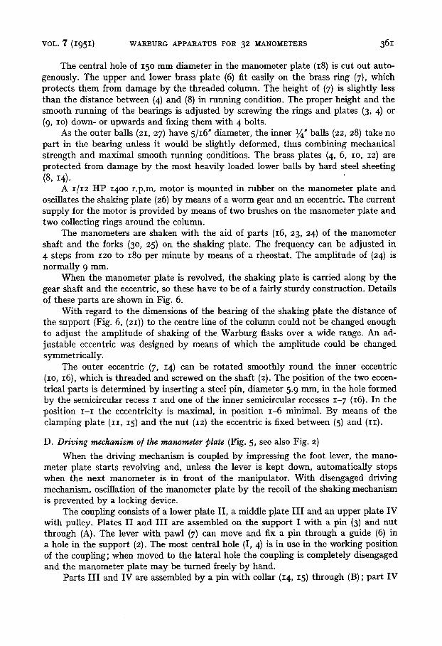
VOL. 7 ( 1 9 5 1 ) WARBURG APPARATUS FOR 32 MANOMETERS 361
The central hole of 15o mm diameter in the manometer plate (18) is cut out auto- genously. The upper and lower brass plate (6) fit easily on the brass ring (7), which protects them from damage by the threaded column. The height of (7) is slightly less than the distance between (4) and (8) in running condition. The proper height and the smooth running of the bearings is adjusted by screwing the rings and plates (3, 4) or (9, IO) down- or upwards and fixing them with 4 bolts.
As the outer balls (21, 27) have 5/16" diameter, the inner ~ " balls (22, 28) take no part in the bearing unless it would be slightly deformed, thus combining mechanical strength and maximal smooth running conditions. The brass plates (4, 6, IO, 12) are protected from damage by the most heavily loaded lower balls by hard steel sheeting (8, 14).
A 1/12 HP 14oo r.p.m, motor is mounted in rubber on the manometer plate and oscillates the shaking plate (26) by means of a worm gear and an eccentric. The current supply for the motor is provided by means of two brushes on the manometer plate and two collecting rings around the column.
The manometers are shaken with the aid of parts (16, 23, 24) of the manometer shaft and the forks (3 o, 25) on the shaking plate. The frequency can be adjusted in 4 steps from 12o to 18o per minute by means of a rheostat. The amplitude of (24) is normally 9 mm.
When the manometer plate is revolved, the shaking plate is carried along by the gear shaft and the eccentric, so these have to be of a fairly sturdy construction. Details of these parts are shown ill Fig. 6.
With regard to the dimensions of the bearing of the shaking plate the distance of the support (Fig. 6, (21)) to the centre line of the column could not be changed enough to adjust the amplitude of shaking of the Warburg flasks over a wide range. An ad- justable eccentric was designed by means of which the amplitude could be changed symmetrically.
The outer eccentric (7, 14) can be rotated smoothly round the inner eccentric (io, i6), which is threaded and screwed on the shaft (2). The position of the two eccen- trical parts is determined by inserting a steel pin, diameter 5.9 mm, in the hole formed by the semicircular recess I and one of the inner semicircular recesses 1- 7 (I6). In the position I - I the eccentricity is maximal, in position I--6 minimal. By means of the clamping plate (II, 15) and the nut (I2) the eccentric is fixed between (5) and (II).
D. Driving mechanism of the manometer plate {Fig. 5, see also Fig. 2)
When the driving mechanism is coupled by impressing the foot lever, the mano- meter plate starts revolving and, unless the lever is kept down, automatically stops when the next manometer is in front of the manipulator. With disengaged driving mechanism, oscillation of the manometer plate by the recoil of the shaking mechanism is prevented by a locking device.
The coupling consists of a lower plate II, a middle plate I n and an upper plate IV with pulley. Plates n and I I I are assembled on the support I with a pin (3) and nut through (A). The lever with pawl (7) can move and fix a pin through a guide (6) in a hole in the support (2). The most central hole (I, 4) is in use in the working position of the coupling; when moved to the lateral hole the coupling is completely disengaged and the manometer plate may be turned freely by hand.
Parts I I I and IV are assembled by a pin with collar (14, 15) through (B) ; part IV

362 j .A. NIEMEIJER VOL. 7 (1951)
1 I,", _ _ _ ~ - _ - - - - - - . . . . d~---L ~ T
zz
I 3 1 1 ] .
Ji ~ e ~ ; ~ ~-°
- ~ ! r i , ~ I ~
~; ,~_ ,~o_+_:~ I' --< ®
lq'ig..5. D l " iv ing mechan ism o f "d',-e manomete r p la te {numbers between bra.okets re fer to oth.er v iews o r secl;io'ns). Scale ]" : 3.
See lurther next page
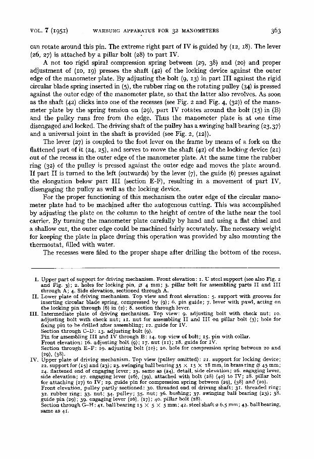
VOL. 7 ( I 9 5 I ) WARBURG APPARATUS FOR 32 MANOMETERS 363
can rotate around this pin. The extreme right part of IV is guided by (12, I8). The lever (26, 27) is attached by a pillar bolt (28) to part IV.
A not too rigid spiral compression spring between (29, 38) and (20) and proper adjustment of (IO, 19) presses the shaft (42) of the locking device against the outer edge of the manometer plate. By adjusting the bolt (9, 13) in part I I I against the rigid circular blade spring inserted in (5), the rubber ring on the rotating pulley (34) is pressed against the outer edge of the manometer plate, so that the latter also revolves. As soon as the shaft (42) clicks into one of the recesses (see Fig. 2 and Fig. 4, (32)) of the mano- meter plate by the spring tension on (29), part IV rotates around the bolt (15) in (B) and the pulley runs flee from the edge. Thus the manometer plate is at one time disengaged and locked. The driving shaft of the pulley has a ~winging ball bearing (23, 37) and a universal joint in the shaft is provided (see Fig. 2, (12)).
The lever (27) is coupled to the foot lever on the flame by means of a fork on the flattened part of it (24, 25), and serves to move the shaft (42) of the locking device (21) out of the recess in the outer edge of the manometer plate. At the same time the rubber ring (32 ) of the pulley is pressed against the outer edge and moves the plate around. If part II is turned to the left (outwards) by the lever (7), the guide (6) presses against the elongation below part I I I (section E-F), resulting in a movement of part IV, disengaging the pulley as well as the locking device.
For the proper functioning of this mechanism the outer edge of the circular mano- meter plate had to be machined after the autogenous cutting. This was accomplished by adjusting the plate on the column to the height of centre of the lathe near the tool carrier. By turning the manometer plate carefully by hand and using a flat chisel and a shallow cut, the outer edge could be machined fairly accurately. The necessary weight for keeping the plate in place during this operation was provided by also mounting the thermostat, filled with water.
The recesses were filed to the proper shape after drilling the bottom of the recess.
I. Upper par t of support for driving mechanism. F ron t elevation: i. U steel support (see also Fig. 2 and Fig. 3); 2. holes for locking pin, ~ 4 mm; 3. pil lar bolt for assembling parts I I and I I I through A; 4. Side elevation, sectioned through A.
II . Lower plate of driving mechanism. Top view and front elevation: 5. support with grooves for insert ing circular blade spring, compressed by (9); 6. pin guide; 7. lever with pawl, acting on the locking pin through (5) in (2) ; 8. section through lever.
III . In termedia te plate of driving mechanism. Top view: 9. adjust ing bolt wi th check nut ; IO. adjust ing bolt wi th check nu t ; zI. nu t for assembling I I and I I I on pillar bolt (3); hole for fixing pin to be dril led after assembling; 12. guide for IV. Section through C-D : 13. adjust ing bol t (9). Pin for assembling I I I and IV through B: 14. top view of bol t ; 15. pin with collar. F ron t elevation: 16. adjust ing bolt (9); I7. nu t (1I); 18. guide for IV. Section through E - F : I9. adjust ing bolt (io); 2o. hole for compression spring between 2o and (29), (38).
IV. Upper plate of driving mechanism. Top view (pulley omitted): 21. support for locking device; 22. support for (15) and (23) ; 23. swinging bal l bearing 35 × 15 × 18 mm, in brass ring ~ 45 ram; 24. f lat tened end of engaging lever; 25. same as (24), detail, side elevat ion; 26. engaging lever, side elevat ion; 27. engaging lever (26), (39), a t tached with bolt (28) (4 o) to IV; 28. pillar bolt for a t taching (27) to IV; 29. guide pin for compression spring between (29), (38) and (2o). Fron t elevation, pulley par t ly sectioned: 3o. threaded end of driving shaft ; 31. threaded ring; 32 . rubber r ing; 33. nu t ; 34. pulley; 35. nu t ; 36 . bushing; 37. swinging ball bearing (23); 38. guide pin (29) ; 39. engaging lever (26), (27) ; 4 o. pil lar bol t (28). Section through G - H : 4 I. bal l bearing 15 × 5 × 5 ram; 42. steel shaft 0 6.5 mm; 43. bal l bearing, same as 41 .
364 j.A. NIEMEIJER VOL. 7 (I95I)
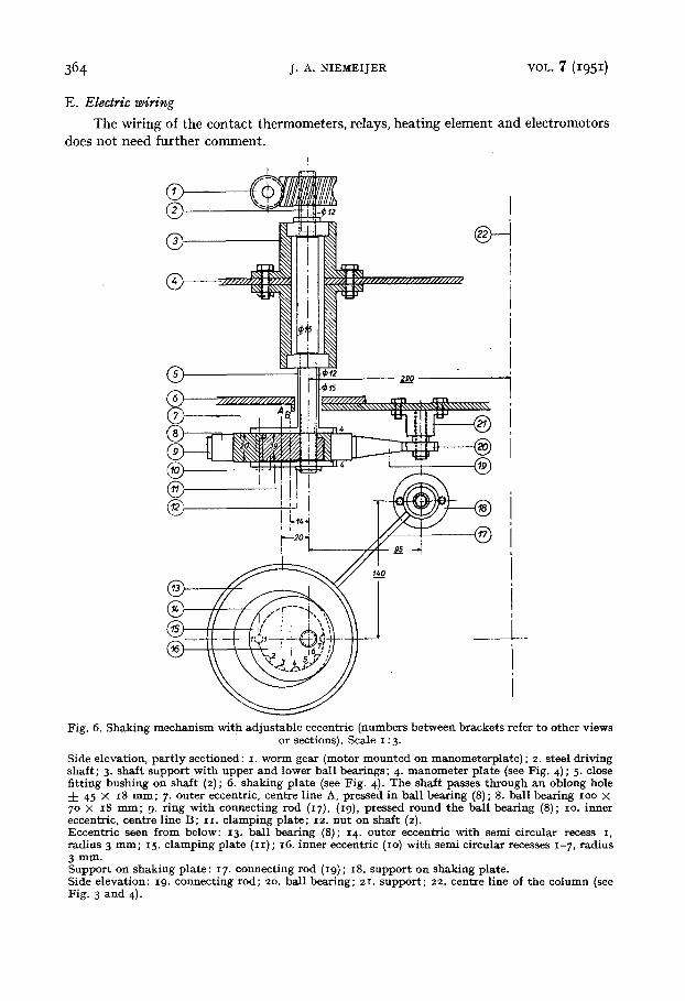
E. Electric wiring
The wiring of the contact thermometers, relays, heating element and electromotors does not need further comment.
T _ 1 i i
Fig. 6. Shaking mechan i sm wi th ad jus tab le eccentr ic (numbers be tween brackets refer to o ther views or sections). Scale I : 3.
Side elevat ion, pa r t l y sect ioned : I. worm gear (motor moun ted on manometerp la te ) ; 2. steel dr iving shaf t ; 3. shaf t suppor t wi th upper and lower bal l bearings; 4- manomete r p la te (see Fig. 4); 5- close f i t t ing bushing on shaf t (2); 6. shaking p la te (see Fig. 4). The shaf t passes th rough an oblong hole 4- 45 × 18 m m ; 7- outer eccentric, centre l ine A, pressed in bal l bear ing (8) ; 8. bal l bearing ioo × 7o × 18 m m ; 9. r ing wi th connect ing rod (17), (I9), pressed round the bal l bearing (8); io. inner eccentric, cent re l ine B; I I . c lamping p la te ; i2. nu t on shaf t (2). Eccent r ic seen f rom below: I3. bal l bearing (8); 14. outer eccentr ic wi th semi circular recess i, radius 3 m m ; 15. c lamping p la te ( i i ) ; i6. inner eccentr ic (io) wi th semi circular recesses 1-7, radius 3 mm. Suppor t on shaking p la te : 17. connect ing rod (I9); 18. suppor t on shaking plate. Side e levat ion: I9. connec t ing rod; 2o. ball bear ing; 21. suppor t ; 22. centre line of the co lumn (see Fig. 3 and 4).
VOL. 7 (1951) WARBURG APPARATUS FOR 32 MANOMETERS 365
The apparatus has been in almost continuous use for more than one year without defects and has fully answered expectations.
Blueprints of the original drawings of the apparatus are available for those who seriously consider the construction of a similar instrument.
Our acknowledgements are due to the staff of the laboratory workshop, in particular to Mr V~. F. MUNHARDT and Mr P. A. DE RIDDER, for the great care and ability with which the construction was carried out.
SUMMARY
The construction of a circular Warburg apparatus for 32 manometers is described.
R]~SUM~
On d6crit la construction d'un appareil Warburg circulaire, pour 32 manom~tres.
ZUSAMMEBIFASSUNG
Beschreibung der Konstruktion eines zirkul~ren VCarburg-Apparates ffir 32 Manometer.
Received December I2th, I95o