Embed Size (px)
Citation preview

GEDA® 300 Z / ZP
Page 1 of 101 Rev.: 001 BL 121 EN Translation of the original operating manual 2011 / 05
Operating Manual
Construction Hoist / Transport Platform For loads and persons

GEDA® 300 Z / ZP
Page 2 of 101 Rev.: 001 BL 121 EN Translation of the original operating manual 2011 / 05
GEDA® 300 Z / ZP
Page 3 of 101 Rev.: 001 BL 121 EN Translation of the original operating manual 2011 / 05
INSTRUCTION MANUAL EC Declaration of Conformity
1 GUIDE ..........................................................................................................................7
1.1 IMAGES .............................................................................................................................................. 7 1.2 WARNING NOTICES ............................................................................................................................. 7 1.3 OVERVIEW OF WARNINGS IN THE MANUAL............................................................................................. 8
1.3.1 Electric shock............................................................................................................................... 8 1.3.2 Crushing by car............................................................................................................................ 8 1.3.3 Do not use the hoist in the event of fire ....................................................................................... 8 1.3.4 Reaching into the travel path during operation............................................................................ 8 1.3.5 Secure machine against being switched on ................................................................................ 9 1.3.6 Falling tools / parts....................................................................................................................... 9 1.3.7 Fall and trip hazard ...................................................................................................................... 9 1.3.8 Suspended loads ......................................................................................................................... 9 1.3.9 Prevent access for unauthorised persons ................................................................................... 9 1.3.10 Wear safety clothing .............................................................................................................. 10
1.4 ABBREVIATIONS................................................................................................................................ 11 1.5 IMPRINT ........................................................................................................................................... 11
2 IDENTIFICATION DATA............................................................................................12
2.1 MACHINE.......................................................................................................................................... 12 2.2 MANUFACTURER............................................................................................................................... 12 2.3 GEDA REPRESENTATIVES ................................................................................................................ 13 2.4 ORDERING SPARE PARTS .................................................................................................................. 13
3 TECHNICAL DATA....................................................................................................14
3.1 SPEEDS ........................................................................................................................................... 14 3.2 DRIVES ............................................................................................................................................ 14 3.3 ASSEMBLY HEIGHT............................................................................................................................ 14 3.4 EMISSIONS ....................................................................................................................................... 14 3.5 DIMENSIONS AND WEIGHT ................................................................................................................. 15
3.5.1 Base unit / platform / cable box: ................................................................................................ 15 3.5.2 Mast section............................................................................................................................... 15 3.5.3 Landing-level safety gates ......................................................................................................... 15
3.6 MAST............................................................................................................................................... 16 3.6.1 Inclination of mast ...................................................................................................................... 16
3.7 TECHNICAL INFORMATION ON ASSEMBLY ............................................................................................ 16 3.7.1 Foundation ................................................................................................................................. 16 3.7.2 Soil pressure .............................................................................................................................. 16
3.8 TIGHTENING TORQUES ...................................................................................................................... 17 3.8.1 Mechanical screw connections without torque control .............................................................. 17 3.8.2 Mechanical screw connections with torque control ................................................................... 17 3.8.3 Electrical screw connections (metal screw connections)........................................................... 17
3.9 SAFETY DISTANCE FROM LIVE WIRES.................................................................................................. 17 3.9.1 European wind regions .............................................................................................................. 18 3.9.2 Assembly geometry ................................................................................................................... 19 3.9.3 Anchoring forces ........................................................................................................................ 22 3.9.4 Stiffener tubes............................................................................................................................ 24 3.9.5 Operating materials.................................................................................................................... 25 3.9.6 Electrics...................................................................................................................................... 25 3.9.7 Tests .......................................................................................................................................... 26 3.9.8 Operating and environmental conditions ................................................................................... 26

GEDA® 300 Z / ZP
Page 4 of 101 Rev.: 001 BL 121 EN Translation of the original operating manual 2011 / 05
4 SAFETY INFORMATION ...........................................................................................27
4.1 PROPER USE .................................................................................................................................... 27 4.2 MACHINE LIMITS ............................................................................................................................... 27 4.3 MODIFICATIONS / ALTERATIONS ......................................................................................................... 27 4.4 LINKING TO OTHER MACHINERY.......................................................................................................... 28 4.5 PROHIBITION OF CERTAIN ACTIVITIES ................................................................................................. 28 4.6 MACHINE OPERATION........................................................................................................................ 28 4.7 FORESEEABLE MISUSE ...................................................................................................................... 28 4.8 MACHINE HAZARDS ........................................................................................................................... 29 4.9 HAZARD SOURCES / EXISTING RESIDUAL HAZARDS .............................................................................. 29
4.9.1 Moving, rotating, pointed and sharp-edged parts ...................................................................... 29 4.9.2 Energies..................................................................................................................................... 29 4.9.3 Operating materials.................................................................................................................... 29 4.9.4 Emergency................................................................................................................................. 29
4.10 OTHER RELEVANT DOCUMENTS ......................................................................................................... 30 4.11 EXPORT LICENCE .............................................................................................................................. 30 4.12 WARRANTY ...................................................................................................................................... 30 4.13 GEDA TRAINING SESSIONS ............................................................................................................... 30
5 OBLIGATIONS OF THE OPERATING COMPANY ...................................................31
5.1 OBLIGATION OF TRAINING / QUALIFICATION ......................................................................................... 31 5.2 ACCESSIBILITY TO NECESSARY INFORMATION ..................................................................................... 32 5.3 CHECKING THE CORRECT AND PROPER CONDITION AND USE ............................................................... 32 5.4 IDENTIFYING HAZARDS AT THE PLACE OF USE ..................................................................................... 32 5.5 MACHINES / SYSTEMS REQUIRING REGISTRATION ............................................................................... 32 5.6 RECURRING INSPECTIONS ................................................................................................................. 32 5.7 TRANSPORTING SUSPENDED LOADS OVER THE MACHINE ..................................................................... 33 5.8 PREPARING AN EMERGENCY / EVACUATION PLAN ................................................................................ 33 5.9 TRAINING ASSEMBLY ENGINEERS FROM OTHER COMPANIES................................................................. 33 5.10 FOLLOWING THE INSTRUCTIONS OF GEDA ASSEMBLY ENGINEERS ...................................................... 33 5.11 PROVISION OF PERSONAL PROTECTIVE EQUIPMENT ............................................................................ 33
6 REGARDING USE BY AUTHORISED PEOPLE .......................................................34
6.1 OPERATOR....................................................................................................................................... 34 6.2 ATTENDANT / PLATFORM OPERATOR .................................................................................................. 34 6.3 PROFESSIONALS FOR MAINTENANCE / SERVICING ............................................................................... 34 6.4 PROTECTION OF PARTICULAR GROUPS OF PEOPLE.............................................................................. 34
6.4.1 Young people, pregnant women, disabled persons .................................................................. 34 6.4.2 People with pacemakers and metal implants ............................................................................ 34
7 OBLIGATORY SAFETY INSTRUCTIONS.................................................................35
7.1 BASIC CONDUCT WHEN WORKING WITH THE MACHINE ......................................................................... 35 7.2 TRANSPORTING THE MACHINE / DISPOSING OF THE MACHINE ............................................................... 36 7.3 SET-UP AND CONNECTION / INSTALLATION .......................................................................................... 37 7.4 FIRST COMMISSIONING / DAILY COMMISSIONING .................................................................................. 38 7.5 TRANSPORTING PEOPLE.................................................................................................................... 39 7.6 TRANSPORTING MATERIAL ................................................................................................................. 40 7.7 SERVICING / REPAIRS / MAINTENANCE / WORK ON ELECTRICAL COMPONENTS ....................................... 41 7.8 CLEANING ........................................................................................................................................ 42 7.9 CONDUCT IN AN EMERGENCY............................................................................................................. 42
7.9.1 Hazard area can be left.............................................................................................................. 43 7.9.2 Hazard area cannot be left......................................................................................................... 43
7.10 SUPPLEMENTARY SAFETY INSTRUCTIONS - COMPONENTS FROM OTHER MANUFACTURERS .................... 43

GEDA® 300 Z / ZP
Page 5 of 101 Rev.: 001 BL 121 EN Translation of the original operating manual 2011 / 05
8 BRIEF DESCRIPTION OF THE MACHINE................................................................44
9 OPERATING AND CONTROL ELEMENTS ..............................................................46
9.1 MASTER SWITCH............................................................................................................................... 46 9.2 CAR CONTROL .................................................................................................................................. 46 9.3 MANUAL CONTROL ............................................................................................................................ 47 9.4 OVERLOAD CONTROL LAMP AND SOCKET OUTLET ............................................................................... 47 9.5 GROUND STATION CAR ACCESS RAMP ................................................................................................ 48 9.6 BUILDING CAR ACCESS RAMP............................................................................................................. 49 9.7 DROP-TEST CONTROL UNIT................................................................................................................ 50
10 SAFETY AND EMERGENCY EQUIPMENT ..............................................................51
10.1 EMERGENCY STOP...................................................................................................................... 52 10.2 TRIGGERING AN EMERGENCY STOP / MACHINE SHUT-DOWN IN EVENTS OF EMERGENCY.................. 52 10.3 ENDING THE EMERGENCY STOP SITUATION .................................................................................. 52 10.4 DEFECT AFTER AN EMERGENCY STOP SITUATION ......................................................................... 52 10.5 LOCATION OF THE EMERGENCY STOP BUTTONS ........................................................................... 53 10.6 SAFETY STOP ................................................................................................................................... 54 10.7 SAFETY GEAR................................................................................................................................... 54 10.8 EMERGENCY LIMIT SWITCH............................................................................................................ 54 10.9 LOCKS TO PREVENT UNAUTHORISED USE ........................................................................................... 54 10.10 EMERGENCY LOWERING (BRAKE RELEASE LEVER) .......................................................................... 55
11 COUNTRY-SPECIFIC EQUIPMENT VARIANTS / ACCESSORIES..........................56
11.1 COLLISION GRILLE ............................................................................................................................ 56 11.2 ROOF............................................................................................................................................... 56 11.3 ASSEMBLY BRIDGE............................................................................................................................ 57 11.4 REPLACE THE CABLE BOX.................................................................................................................. 57 11.5 CONVERTING ACCESS TO THE FRONT END / ADDING A SECOND ACCESS ............................................... 58 11.6 ENCLOSURE WITH BARRIER ............................................................................................................... 59 11.7 HOLDER FOR INDIVIDUAL SUPPORT FRAMES ....................................................................................... 60 11.8 COLD PACKAGE ................................................................................................................................ 60 11.9 OPERATING TIME INDICATOR ............................................................................................................. 60
12 DAILY INSPECTIONS BEFORE STARTING WORK ................................................61
12.1 VISUAL INSPECTIONS ........................................................................................................................ 61 12.2 FUNCTION TESTS .............................................................................................................................. 62
12.2.1 Test run with an empty car .................................................................................................... 62 12.2.2 Test run by platform operator / person authorised to carry out tests and inspections .......... 62
13 RESCUING PEOPLE TRAPPED INSIDE ..................................................................63
13.1 BASIC CONDUCT IN THE EVENT OF A RESCUE / MALFUNCTION .............................................................. 63 13.2 RESCUE MEASURES PLAN.................................................................................................................. 64 13.3 RESCUING PEOPLE FROM THE CAR .................................................................................................... 65
14 CLEANING.................................................................................................................66
14.1 CLEANING THE MACHINE INSIDE AND OUT ........................................................................................... 66 14.2 CLEANING THE AREA AROUND THE MACHINE ....................................................................................... 66

GEDA® 300 Z / ZP
Page 6 of 101 Rev.: 001 BL 121 EN Translation of the original operating manual 2011 / 05
15 ASSEMBLY................................................................................................................67
15.1 TRANSPORT TO THE ASSEMBLY LOCATION.......................................................................................... 69 15.2 ASSEMBLY PLAN ............................................................................................................................... 70 15.3 ASSEMBLING THE BASE UNIT.............................................................................................................. 71 15.4 MOUNTING THE FIRST MAST TIE ......................................................................................................... 71 15.5 TRANSPORT THROUGH NARROW SPACES ........................................................................................... 72
15.5.1 Dismantling the accesses...................................................................................................... 73 15.5.2 Dismantling the front wall ...................................................................................................... 74 15.5.3 Folding up the car.................................................................................................................. 74 15.5.4 Remove protective buffers..................................................................................................... 75 15.5.5 Unscrew foot section ............................................................................................................. 75 15.5.6 Installation at the assembly location...................................................................................... 75 15.5.7 Inspection after assembly...................................................................................................... 75
15.6 ASSEMBLY / ANCHORING OF THE MAST ............................................................................................... 76 15.6.1 Assembling the mast fixture .................................................................................................. 77 15.6.2 Trailing cable guide ............................................................................................................... 78 15.6.3 Using the assembly bridge .................................................................................................... 79 15.6.4 Assembling the EMERGENCY limit switch bar ..................................................................... 80
1.1 LANDING-LEVEL LIMIT SWITCH BAR................................................................................................ 80 15.6.5 Securing loading and unloading points ................................................................................. 80 15.6.6 Checks after assembly / checks prior to initial commissioning ............................................. 81
16 DISASSEMBLY..........................................................................................................81
17 DISPOSING OF THE MACHINE................................................................................81
18 MAINTENANCE .........................................................................................................82
18.1 WARNINGS AND SAFETY INSTRUCTIONS TO BE COMPLIED WITH DURING MAINTENANCE / SERVICING ....... 82 18.2 MAINTENANCE PLAN.......................................................................................................................... 83 18.3 INSPECTIONS.................................................................................................................................... 84 18.4 VISUAL INSPECTIONS ........................................................................................................................ 85
18.4.1 Test run with an empty car .................................................................................................... 86 18.4.2 Test run by platform operator / person authorised to carry out tests and inspections .......... 86
18.5 REFILLING AND INSPECTION JOBS ...................................................................................................... 87 18.5.1 Lubrication device.................................................................................................................. 87
18.6 CHECKING FOR WEAR ....................................................................................................................... 88 18.6.1 Drive pinion............................................................................................................................ 88 18.6.2 Gear rack ............................................................................................................................... 88 18.6.3 Tracks rollers ......................................................................................................................... 89 18.6.4 Motor brake............................................................................................................................ 90
18.7 FUNCTION TESTS .............................................................................................................................. 91 18.7.1 Safety gear ............................................................................................................................ 91 18.7.2 Drop test passed ................................................................................................................... 92 18.7.3 Drop test not passed ............................................................................................................. 92 18.7.4 Check safety gear for damage .............................................................................................. 93 18.7.5 Safety gear replacement ....................................................................................................... 93
18.8 FAULT TABLE .................................................................................................................................... 94
19 DOCUMENTING THE CHECKS ................................................................................95

GEDA® 300 Z / ZP
Page 7 of 101 Rev.: 001 BL 121 EN Translation of the original operating manual 2011 / 05
1 Guide You will come across a series of illustrations and symbols while reading this manual which are intended to help you navigate through and under-stand this manual. The different meanings are explained below.
Text display
Meaning
Bold type Emphasises particularly important words / passages
List 1 Denotes lists o List 2 Denotes lists
(brackets) Item numbers Instruction Instruction to personnel Always given in
chronological order The masculine form of address is mostly used in this manual to make reading easier. It goes without saying that both genders are always implied and addressed.
1.1 Images The images used refer to a specific machine type. They may only be a schematic representation of other machine types. The fundamental func-tion and operation is not affected by this.
1.2 Warning notices Activities with specific hazards (to life and limb or potential damage to the machine) are indicated by warning notices. The instructions given in the warning notices must be observed.
Warning level Consequence Probability death / serious injury is imminent
serious injury possible
minor injury possible
material damage possible

GEDA® 300 Z / ZP
Page 8 of 101 Rev.: 001 BL 121 EN Translation of the original operating manual 2011 / 05
1.3 Overview of warnings in the manual
1.3.1 Electric shock
1.3.2 Crushing by car
DANGER
Danger to life by crushing. Never stand underneath the car / In the hazard area during operation. Turn the master switch off and secure against being switched back on while working in the hazard area.
1.3.3 Do not use the hoist in the event of fire
1.3.4 Reaching into the travel path during operation
DANGER
Electric shock Parts remain live even after actuating the EMERGENCY STOP or after switching off the machine at the master switch. Applies to all work on electrical parts. Disconnect mains supply upstream from the master switch.
DANGER
Danger to life Do not use the hoist in the case of fire.
DANGER
Danger to life Crushing or amputation of limbs. Never reach into the travel path of the machine during operation.

GEDA® 300 Z / ZP
Page 9 of 101 Rev.: 001 BL 121 EN Translation of the original operating manual 2011 / 05
1.3.5 Secure machine against being switched on
1.3.6 Falling tools / parts
1.3.7 Fall and trip hazard
1.3.8 Suspended loads
1.3.9 Prevent access for unauthorised persons
DANGER
Danger to life Due to the machine being switched on during servicing / repair work or when there is a defect. Secure master switch with a padlock to prevent it from being switched on.
DANGER
Danger to life Falling tools / parts. Secure tools / parts against falling. Use the car roof.
WARNING
Fall and trip hazard Look out for steps and objects on the ground when entering / exiting the car.
WARNING
Danger to life Raised load. Do not stand under suspended loads. Do not stand on suspended loads. Only lift loads at the suspension points. Only use suitable lifting gear.
WARNING
Danger to life Access only for authorised individuals. No access for unauthorised individuals.

GEDA® 300 Z / ZP
Page 10 of 101 Rev.: 001 BL 121 EN Translation of the original operating manual 2011 / 05
1.3.10 Wear safety clothing
DANGER
Danger to life Risk of fire and explosion as a result of using combustible cleaning materials. Only use suitable, non-combustible cleaning agents. Do not use steam-jet equipment / high-pressure cleaners. This can damage electrical components. Do not touch sockets, cables or electrical compo-nents with wet or damp hands. Cleaning work on live components must only be carried out by qualified electrical personnel. Wear personal protective equipment.

GEDA® 300 Z / ZP
Page 11 of 101 Rev.: 001 BL 121 EN Translation of the original operating manual 2011 / 05
1.4 Abbreviations The following abbreviations may be used in the manual.
max. maximum min. minimum mins. minutes etc. et cetera poss. possible / possibly e.g. for example ml millilitre mm millimetre °C degrees Celsius °F degrees Fahrenheit ft. feet ft/m feet per minute m/min metres per minute in. inch etc. et cetera lbs. pounds lbf.-ft pounds per feet kg kilogram l litre gal. gallons kip kilopound
Nm Newton metre km/h kilometres per hour mph miles per hour inc. including if nec. if necessary i.e. i.e. reg. regarding RH relative humidity approx. approximately Ø diameter ® registered trademark © copyright TM trademark (trade
name) % per cent ‰ per mille dB (A) sound pressure level LWA sound power level > greater than < less than ± plus or minus
1.5 Imprint GEDA Dechentreiter GmbH & Co. KG Copyright © All rights reserved. No part may be reproduced in any form or processed, duplicated or disseminated using electronic media without the written con-sent of the manufacturer. The copyright and conditions of use of any soft-ware products / user documentation from other manufacturers that may be included with the scope of delivery must be observed.

GEDA® 300 Z / ZP
Page 12 of 101 Rev.: 001 BL 121 EN Translation of the original operating manual 2011 / 05
2 Identification data
2.1 Machine Machine model 300 Z / ZP Year of manufacture See nameplate
2.2 Manufacturer GEDA Dechentreiter GmbH & Co. KG Street: Mertinger Straße 60 Town / city: DE-86663 Asbach-Bäumenheim Country: Germany Tel.: +49 (0)9 06 / 98 09-0 Fax: +49 (0)9 06 / 98 09-50 Email: [email protected] Home page: www.geda.de

GEDA® 300 Z / ZP
Page 13 of 101 Rev.: 001 BL 121 EN Translation of the original operating manual 2011 / 05
2.3 GEDA representatives Northwest branch East branch GEDA Dechentreiter GmbH & Co. KGMarie-Curie-Straße 11 D-59192 Bergkamen-Rünthe Tel. +49(0)2389 9874-32 Fax +49(0)2389 9874-33
GEDA Dechentreiter GmbH & Co. KG Ernst-M.-Jahr Straße 5 D-07552 Gera Tel. +49(0)365 55280-0 Fax +49(0)365 55280-29
GEDA USA, LLC GEDA RUSSIA P.O. BOX 752086 USA 77275 Houston, Texas Tel. +1(713) 621 7272 Fax +1(713) 621 7279
Yaroslavskoe shosse 42 129337 Moscow Tel. +7(495) 663 24 48 Fax +7(495) 663 24 49
2.4 Ordering spare parts
Spare parts are ordered exclusively through the manufacturer / represen-tative. Only original GEDA spare parts may be used. Only original GEDA spare parts guarantee full function as well as safety and reliability. The use of unapproved spare parts releases us from any liability for damage arising as a consequence of such use. Please supply the following details with each order for spare parts:
Machine model
Year of manufacture
Serial No.
Name of the component
Item-No.
Order quantity
Operating voltage (if applicable)

GEDA® 300 Z / ZP
Page 14 of 101 Rev.: 001 BL 121 EN Translation of the original operating manual 2011 / 05
3 Technical data
3.1 Speeds 400 V Travel: (12 m/min.) In the safety area (0-2 m) Car control unit (12 m/min. or 9 m/min#) External control unit (12 m/min. or 9 m/min#) Load capacity: Standard operation / assembly 500 kg / 300 kg 230 V Travel: (12 m/min.) In the safety area (0-2 m) Car control unit (12 m/min. or 9 m/min#) External control unit (12 m/min. or 9 m/min#) Load capacity: Standard operation / assembly 300 kg / 300 kg
Safety gear Triggering speed (22 m/min.)
3.2 Drives 400 V Power 1.9 kW Nominal current 4.6 A Start-up current (max.) 23 A 230 V Power 1.7 kW Nominal current 11 A Start-up current (max.) 31 A
3.3 Assembly height
230 V max. 50 m
3.4 Emissions Sound power level LWA: # 9 m/min. may be stipulated by national provisions.
GEDA® 300 Z / ZP
Page 15 of 101 Rev.: 001 BL 121 EN Translation of the original operating manual 2011 / 05
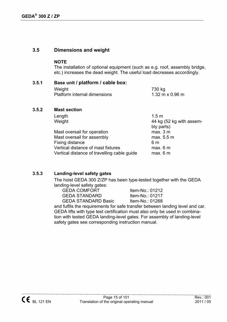
3.5 Dimensions and weight NOTE The installation of optional equipment (such as e.g. roof, assembly bridge, etc.) increases the dead weight. The useful load decreases accordingly.
3.5.1 Base unit / platform / cable box:
Weight 730 kg Platform internal dimensions 1.32 m x 0.96 m
3.5.2 Mast section Length 1.5 m Weight 44 kg (52 kg with assem-
bly parts) Mast oversail for operation max. 3 m Mast oversail for assembly max. 5.5 m Fixing distance 6 m Vertical distance of mast fixtures max. 6 m Vertical distance of travelling cable guide max. 6 m
3.5.3 Landing-level safety gates The hoist GEDA 300 Z/ZP has been type-tested together with the GEDA landing-level safety gates:
GEDA COMFORT Item-No.: 01212 GEDA STANDARD Item-No.: 01217 GEDA STANDARD Basic Item-No.: 01268
and fulfils the requirements for safe transfer between landing level and car. GEDA lifts with type test certification must also only be used in combina-tion with tested GEDA landing-level gates. For assembly of landing-level safety gates see corresponding instruction manual.

GEDA® 300 Z / ZP
Page 16 of 101 Rev.: 001 BL 121 EN Translation of the original operating manual 2011 / 05
3.6 Mast
3.6.1 Inclination of mast Vertical inclination of the mast max. 0.5°. Check inclination during and fol-lowing installation using appropriate means.
3.7 Technical information on assembly
3.7.1 Foundation The foundation must reliably transfer existing loads into the subsoil. The following points must therefore be ensured before each installation operation.
Evidence of the load-bearing capacity of the foundation
Evidence of the load-bearing capacity of the subsoil
Since the load-bearing capacity of the subsoil is often very difficult to estimate, a specialist soil investigator should be called on if there is even the slightest doubt, in particular for high / complicated superstructures. The following points must be taken into account when assessing the subsoil:
Maximum permissible soil pressure
Predicted settlement
Predicted groundwater levels
Predicted thawing and frost processes
Construction activities expected in direct proximity to the installation site
Steel plates and concrete can be used as load-distributing base supports. The foundation must be horizontal. The ground pressure data includes no safety factors.
3.7.2 Soil pressure
Assembly height [m]
10 20 30 40 50
Weight (kg)
1815 2130 2500 2870 3185
Load-bearing capacity (kN/m²)
73 86 101 115 128

GEDA® 300 Z / ZP
Page 17 of 101 Rev.: 001 BL 121 EN Translation of the original operating manual 2011 / 05
3.8 Tightening torques
3.8.1 Mechanical screw connections without torque control
Data refers to bolts in strength class 8.8 Tightening torque Tightening torque M 8 25 Nm M 16 210 Nm
M 10 49 Nm M 18 300 Nm
M 12 86 Nm M 20 425 Nm
M 14 135 Nm M 24 710 Nm
3.8.2 Mechanical screw connections with torque control
Mast elements to one another 150 Nm Tightening torque Mast tubes
50 Nm Tightening torque
3.8.3 Electrical screw connections (metal screw connections)
Tightening torque Tightening torque M 4 1.2 Nm M 12 15.5 Nm M 5 2 Nm M 16 30 Nm M 6 3 Nm M 20 52 Nm M 8 6 Nm M 24 52 Nm M 10 10 Nm M 30 52 Nm
3.9 Safety distance from live wires The table below shows the minimum safety distances for each machine component from live, non-insulated wires. Country-specific regulations must be observed.
Voltage Minimum distance 0 – 300 V Avoid contact > 300 V to 50 kV 3,0 m > 50 kV to 200 kV 4,5 m > 200 V to 350 kV 6,0 m > 350 V to 500 kV 8,0 m > 500 V to 750 kV 11,0 m > 750 V to 1000 kV 14,0 m

GEDA® 300 Z / ZP
Page 18 of 101 Rev.: 001 BL 121 EN Translation of the original operating manual 2011 / 05
3.9.1 European wind regions
The operating company is responsible for applying the correct wind region. Local conditions such as:
mountains, bays, valleys, house gullies, thoroughfares,
buildings, etc.
can create wind turbulences and make it necessary to apply another wind re-gion. Assembly
height metres
Wind pressures by region (N/m²)
A/B C D E 0 – 10 544 741 968 122510 – 20 627 853 1114 141020 – 50 757 1031 1347 1704

GEDA® 300 Z / ZP
Page 19 of 101 Rev.: 001 BL 121 EN Translation of the original operating manual 2011 / 05
3.9.2 Assembly geometry

GEDA® 300 Z / ZP
Page 20 of 101 Rev.: 001 BL 121 EN Translation of the original operating manual 2011 / 05

GEDA® 300 Z / ZP
Page 21 of 101 Rev.: 001 BL 121 EN Translation of the original operating manual 2011 / 05
Assembly geometry table H Height of the base unit (with assembly bridge) 2,3 m I Max. distance of cable guides 6 m I.1 Max. distance between the first cable guide and the
cable box 1 m
J For left-opening landing-level gate Distance from the centre of the vertical scaffold bar to the centre of the circular mast tube
0.25 m
J.1 For right-opening landing-level gate Distance from the centre of the vertical scaffold bar to the centre of the circular mast tube
0,40 m
J.2 Width of the base unit 1.60 m J.3 For left-opening landing-level gate, platform corner
crossbar to the opened landing-level gate 2.30 m
J.4 For right-opening landing-level gate, distance from the centre of the vertical scaffold bar to the opened land-ing-level gate
1.95 m
J.5 Distance to the additional vertical fixing tube 1.47 m K Distance from the centre of the circular mast tube to
the corner crossbar on the unloading hatch 0.78 m
L Depth of the base unit 1.66 m M Depth of the base unit with opened unloading hatch 2.59 m N Loading height (platform on ground) 0.35 m O Platform width (internal dimensions) 0.96 m P Minimum distance between closed assembly bridge
and fixing tube 0.10 m
Q Platform corner crossbar to the centre of the landing-level gate crossbar tube
0.59 m
S Distance between the centre of the circular mast tube to the centre of the landing-level gate crossbar tube
1.52 m
T Max. assembly height 50 m U Height of first mast bracket 4 m V Vertical distance to remaining mast brackets 6 m W Max. projecting mast 3 m X Distance from emergency limit approach bar to mast
end 1.25 m
Y Distance from the landing floor to the landing limit switch approach bar
0.33 m
Z Tightening torque of the mast connection bolts 150 Nm

GEDA® 300 Z / ZP
Page 22 of 101 Rev.: 001 BL 121 EN Translation of the original operating manual 2011 / 05
3.9.3 Anchoring forces
The anchoring forces must be reliably absorbed by the building structure / scaffolding. This may need to be checked by a qualified construction professional. The choice of fastening elements depends on the prevailing conditions (wall plugs / through-bolts). The anchoring forces can be taken from the table below. The table specifies peak forces for the assembly geometry shown, which do not yet include any safety factors. The appro-priate anchoring forces must be requested if the assembly geometry shown is changed.
Assembly in front of a wall A = 1.1 m; B = 1.58 m; C = max. 0.2 m
Top anchor point
(Mast projection 3 m) Other anchor points
(or top anchor point without mast projection)
Wind region Fx Fy Fx Fy A / B / C 5.4 kN 7.4 kN 3.3 kN 4.6 kN
D 6.8 kN 9.1 kN 4.2 kN 5.6 kN E 8.6 kN 11.5 kN 5.3 kN 7.0 kN

GEDA® 300 Z / ZP
Page 23 of 101 Rev.: 001 BL 121 EN Translation of the original operating manual 2011 / 05
Assembly in front of scaffolding A = 2.5 m; B = 2.48 m; C = 0.2 m
Top anchor point
(Mast projection 3 m) Other anchor points
(or top anchor point without mast projection)
Wind region Fx Fy Fx Fy A / B / C 5.4 kN 5.7 kN 3.3 kN 3.5 kN
D 6.8 kN 6.8 kN 4.2 kN 4.2 kN E 8.6 kN 8.6 kN 5.3 kN 5.3 kN

GEDA® 300 Z / ZP
Page 24 of 101 Rev.: 001 BL 121 EN Translation of the original operating manual 2011 / 05
3.9.4 Stiffener tubes For certain assembly situations (very large distances to fixing points) it may be necessary to protect the anchoring tubes against buckling.
Buckling length
Permissible pressure
force 400 cm 8030 N 450 cm 6460 N 500 cm 5290 N 550 cm 4410 N 600 cm 3730 N 650 cm 3200 N 700 cm 2770 N 750 cm 2420 N 800 cm 2140 N 850 cm 1900 N
The actual pressure forces in the tube must be calculated us-ing the forces stated in the tables. If the specified forces are exceeded, additional measures must be applied.
The table applies for smooth, one-part steel tubes without joint. 48.3 x 3.25 – St 37-2 DIN 2448 or DIN 2458

GEDA® 300 Z / ZP
Page 25 of 101 Rev.: 001 BL 121 EN Translation of the original operating manual 2011 / 05
3.9.5 Operating materials Grease: 2.64 lbs (1.2 kg) Class / quality: NLGI 2 The grease quantity for a lubrication unit is enough for approx. 120 operating hours (3 months/1 shift operation). AGIP GR MU EP or simi-lar quality of grease. (You must observe the mixing capacity of greases.) Gear oil: The motors are lifetime-lubricated. Refilling is not necessary under normal conditions. In the case of heavy use, the oil must be changed every 10,000 operating hours. Filling capacity: See the manufacturer's instructions. Oil types: See gear / motor rating plate.
Contact GEDA before using any other operating materials. Excess quantities must be returned or disposed of in accordance with company guidelines and legal requirements.
3.9.6 Electrics Operating voltage: 400 V / 50 Hz / 3 x 16 A / 3 Ph
230 V / 50 Hz / 1 x 16 A / 3 Ph Safety class: IP 54 (NEMA 3)
The cables provided by the customer must be designed such that:
they correspond to the connected load of the machine.
no interference voltages or interference frequencies occur.
the response behaviour of the safety equipment meets the relevant legal requirements.
The necessary cable cross-section must be determined while taking in-to account the requisite installation type according to DIN VDE 0298 Section 4 and DIN VDE 0100 Section 430. Country-specific regulations must be observed. A rubber hose coated lead of at least 5 x 2.5 mm² (or 3 x 2.5 mm² for 230V drive) is required to extend the power cord.
The machine must only be connected to a building site main cabinet according to IEC 60439-4:2004. Fuse protection min. 16 A / T; residual current device (RCD) with rated current of max. 0.03 A.

GEDA® 300 Z / ZP
Page 26 of 101 Rev.: 001 BL 121 EN Translation of the original operating manual 2011 / 05
3.9.7 Tests The following tests have been carried out prior to delivery:
Dynamic test of the safety gear with 1.25 times the maximum load capacity by means of a drop test.
Electrical tests according to EN 60204.
Function tests.
3.9.8 Operating and environmental conditions
The machine may only be operated when the following operating and environmental conditions are satisfied: Temperature range: minimum −20 °C
maximum +40 °C Wind speed: Operation / maintenance / servicing maximum 72 km/h Installation maximum 45 km/h Weather conditions: No storms with risk of lightning.
It may be necessary to cease / prohibit operation of the machine under ex-treme weather conditions, even if the operating and environmental condi-tions fall within the bounds of those stated. For example, due to the paral-lel occurrence of extreme frost and storms. The operating company must provide appropriate precautions in this regard. Atmosphere: Transporting people: The composition of the atmosphere must be suitable for people remaining in this area. Any reduction in the oxygen concentration as a result of dis-placement or consumption must in particular be prevented. The legal limit values for pollutant concentrations / aerosols and dust in the workplace must not be exceeded. Material transport: When transporting material, this must not lead to a concentration of abra-sive / corrosive substances and of explosive fine particulate matter. If this cannot be excluded with certainty, then the corrosion protection and / or the functional reliability of the electrical components must be inspected at regular intervals and if necessary replaced. Fine particulate matter must be removed.

GEDA® 300 Z / ZP
Page 27 of 101 Rev.: 001 BL 121 EN Translation of the original operating manual 2011 / 05
4 Safety information This safety information must be read and observed by all persons who are entrusted with work on the machine or who supervise or instruct such people. Non-compliance with the safety information releases GEDA from any liability.
4.1 Proper use The machine described in this manual is solely intended for: temporary use on construction sites as:
Construction hoist: For the transport of material Transport platform: For the transport of material and persons (max. 3 persons) Mast-guided climbing platform: For the execution of construction work from the car Scaffolding assembly hoist: For the assembly of scaffolding and mast from the car.
The load-bearing capacities specified in the column for technical data (weight / persons) must be complied with. Improper use, non-compliance with the manual, the use of insufficiently qualified personnel, and the use of non-approved spare parts excludes any liability on the part of the manufacturer.
4.2 Machine limits The machine may only be used while complying with:
the technical data / features.
the max. permissible load bearing capacity and number of persons.
the defined operating and environmental conditions.
4.3 Modifications / alterations Unauthorised modifications / alterations can have an unforeseeable influ-ence on the safety of the machine. For this reason, unauthorised modifica-tions / alterations are prohibited. Any unauthorised modifications that are carried out shall exclude the manufacturer from any liability. This also in-cludes welding, grinding and burning operations on the machine, as well as the control programs.

GEDA® 300 Z / ZP
Page 28 of 101 Rev.: 001 BL 121 EN Translation of the original operating manual 2011 / 05
4.4 Linking to other machinery Control-related or functional linking to other machinery is prohibited and releases GEDA from any liability.
4.5 Prohibition of certain activities The following activities may only be carried out by GEDA employees due to error sources that are potentially unrecognisable (to the operating com-pany):
Repairs to the safety gear
Changes to the control programs
4.6 Machine operation Operation is only permitted in accordance with:
the information on proper use.
the information on the machine limitations.
the information on operating and environmental conditions.
all laws / regulations that must be complied with by the operating company.
all other information in this manual. Starting or operating the machine without having read the manual before-hand is strictly prohibited. The manual must be kept safe for continued and future use with the machine. GEDA shall not be liable for any damage arising from non-compliance with the manual.
4.7 Foreseeable misuse Any use of the machine that deviates from the conditions specified above and from the stated purpose is strictly prohibited.
This in particular includes use:
without correctly installed landing-level safety gates.
at a greater distance from the building / scaffolding than permitted.
without designation of the hazard area.
in a potentially explosive area.
as a crane, means of travel, platform for bungee jumping, convey-ance of persons / materials to publicly accessible places.
as a transport platform for persons without roof mounted, if there is a risk of objects falling into the car.

GEDA® 300 Z / ZP
Page 29 of 101 Rev.: 001 BL 121 EN Translation of the original operating manual 2011 / 05
4.8 Machine hazards The machine has been designed and manufactured according to the cur-rent state of the art. It has been subjected to a safety inspection and ac-ceptance procedure before delivery. Nevertheless, personal hazards or material damage may result if operated incorrectly, used improperly, used without due care and attention, insuffi-ciently serviced or if components fail.
4.9 Hazard sources / existing residual hazards As with all complex machinery, there are also sources of potential hazards in the case of GEDA machines. These are:
4.9.1 Moving, rotating, pointed and sharp-edged parts
Drives
Chains / ropes / cables
4.9.2 Energies
Electricity
Hot surfaces
Potential energy (raised components / tipping / falling loads / falling tools)
4.9.3 Operating materials
Oils
Greases
4.9.4 Emergency
Trapping of persons.

GEDA® 300 Z / ZP
Page 30 of 101 Rev.: 001 BL 121 EN Translation of the original operating manual 2011 / 05
4.10 Other relevant documents In addition to this manual, the following documents must be observed by the corresponding target group:
The manuals for the landing-level safety gates / the electric mod-ules.
Customer service information, if applicable.
Instruction manuals issued by the suppliers of purchased parts These documents must be supplemented by the operating company with the national regulations of the country of use applicable in each case. If the machine is sold or passed on, the documentation must be passed on as well.
4.11 Export licence Parts of the machine / electrical control unit may require export licences depending on the current status of foreign trade law. The customer shall take responsibility for acquiring the relevant export licence and shall only proceed in accordance with this licence.
4.12 Warranty This manual does not contain any warranty agreements. These can be found in the General Terms and Conditions of Business. Proper use is a precondition for the warranty.
4.13 GEDA training sessions GEDA conducts detailed training sessions in order to enable the highest degree of safety and economic efficiency when operating the machine. When the machine is delivered, the operating company and its personnel will receive extensive instruction in function, operation, maintenance, ser-vicing and troubleshooting. The operating company is recommended to take advantage of these training sessions. Please contact the GEDA GmbH customer service department for information on training.

GEDA® 300 Z / ZP
Page 31 of 101 Rev.: 001 BL 121 EN Translation of the original operating manual 2011 / 05
5 Obligations of the operating company
5.1 Obligation of training / qualification The operating company clearly defines the responsibilities of the person-nel for operation / installation / maintenance. The operating company is obliged to train all persons authorised to use the machine in the correct handling of the machine before using it for the first time, according to the respective area of activity and responsibility of the authorised individual and using practical exercises. Training will cover at least the following:
the scope and limitations of the area of activity and responsibility of the group of people in question.
safety-conscious conduct.
Avoidance of hazards during operation.
conduct in an emergency.
application of the emergency / evacuation plan.
correct machine operation.
the meaning of the warning signs, notices and pictograms.
use and inspection of the personal protective equipment.
how to handle operating materials and cleaning agents. Finally, the operating company must check that each person is capable of operating the machine independently and correctly. This training must be documented and repeated at regular intervals. New personnel may only operate the machine under the supervision and instruction of experienced personnel. Maintenance and repair work must only be carried out by personnel quali-fied for this work. The use of non-qualified personnel is prohibited and re-leases GEDA from any liability.

GEDA® 300 Z / ZP
Page 32 of 101 Rev.: 001 BL 121 EN Translation of the original operating manual 2011 / 05
5.2 Accessibility to necessary information The operating company must make the manual required for the relevant task available to all persons who are commissioned with operation, servic-ing and maintenance. The operating company must ensure that the individuals in question have read and understood the necessary manuals. The same applies to all relevant safety data sheets, operational instruc-tions, accident prevention guidelines, and instructions issued by suppliers of purchased parts and service materials. Depending on how the company is organised, the manuals may have to be made available to other individuals / departments.
5.3 Checking the correct and proper condition and use At regular intervals, the operating company must take appropriate meas-ures to check that the machine is being used according to the intended use, that the machine has not been modified or tampered with and that all parts are fully functional.
5.4 Identifying hazards at the place of use The operating company must identify all hazards at the place of use of the machine and must take the necessary health and safety measures.
5.5 Machines / systems requiring registration The operating company must register machines / systems which require registration with the responsible national authorities in accordance with the contents and deadlines of the regulations / obligations.
5.6 Recurring inspections The operating company must have the recurring inspections, which are stipulated and regulated by national law, carried out and the results docu-mented in an appropriate way.

GEDA® 300 Z / ZP
Page 33 of 101 Rev.: 001 BL 121 EN Translation of the original operating manual 2011 / 05
5.7 Transporting suspended loads over the machine The operating company must use appropriate organisational measures to ensure that no suspended loads are transported above the machine.
5.8 Preparing an emergency / evacuation plan The operating company must prepare an emergency / evacuation plan and train all relevant persons in this plan and provide appropriate instruc-tions.
5.9 Training assembly engineers from other companies Before undertaking any work, assembly engineers from other companies must be informed by the operating company about obligatory safety regu-lations, valid accident prevention guidelines as well as the machine's func-tions and safety equipment. The corresponding instructions / manuals must be made available.
5.10 Following the instructions of GEDA assembly engineers If the machine is constructed by GEDA assembly engineers, their instruc-tions must be complied with.
5.11 Provision of personal protective equipment
The operating company must provide personal protective equipment ap-propriate to the respective place of use and purpose. Protective equipment must be checked at regular intervals to ensure func-tion and completeness. All national and trade association regulations relating to protective equip-ment must be observed in addition to this information.

GEDA® 300 Z / ZP
Page 34 of 101 Rev.: 001 BL 121 EN Translation of the original operating manual 2011 / 05
6 Regarding use by authorised people
6.1 Operator A person who, on account of his / her training and experience, is capable of carrying out the functions and activities associated with normal opera-tion. This also includes avoiding potential risks and hazards that may occur dur-ing operation of the machine.
6.2 Attendant / platform operator A person who, on account of his / her training and experience, is capable of starting a machine and carrying out the functions and activities associ-ated with normal operation. This also includes avoiding potential risks and hazards that may occur during operation of the machine / machine start-up. When using as a transport platform, the machine must only be operated by the attendant / platform operator from the car. Furthermore, the attendant / platform operator is responsible for adher-ence to / implementation of the emergency plan.
6.3 Professionals for maintenance / servicing A person who, on account of his / her qualified professional education, training and experience, is able to recognise risks and potential hazards during work / assembly / servicing / repair work on the machine and can rectify these by introducing appropriate measures.
6.4 Protection of particular groups of people
6.4.1 Young people, pregnant women, disabled persons The respective legal occupational restrictions apply.
6.4.2 People with pacemakers and metal implants Magnetic fields which occur in the vicinity of live conductors and motors can present a hazard for the individuals mentioned above. Should it be necessary to enter these areas, a doctor should be consulted beforehand as adverse health effects cannot in principle be ruled out.

GEDA® 300 Z / ZP
Page 35 of 101 Rev.: 001 BL 121 EN Translation of the original operating manual 2011 / 05
7 Obligatory safety instructions
7.1 Basic conduct when working with the machine
The machine must be used with an awareness of hazards, in a technically fault-free condition and according to the instructions in this manual.
Acquaint yourself with the way the machine works, the operating controls and the safety equipment.
The stipulated operating steps and the sequence of steps must be adhered to.
If there is any lack of clarity regarding proper condition or correct operation, these points must be clarified. Operation is prohibited un-til the matter is clarified.
The operator is responsible for third parties in the working area of the machine.
Unauthorised persons must be kept away from the machine; if nec-essary set up warning notices.
All safety regulations relevant to the respective job / activity must be adhered to.
Responsibilities for different activities must be clearly identified and adhered to. Lack of clarity greatly compromises safety.
Safety and emergency equipment may neither be removed, altered nor made ineffective and must be inspected at regular intervals to ensure function and completeness.
Rectify any faults which fall within your area of responsibility.
If faults occur outside your area of responsibility, inform your supe-rior immediately.
In the event of wind speeds > (72 km / h), bring the car down to the ground and cease operation.
Smoking, eating, drinking and naked flames are prohibited.
Wear personal protective equipment.
During all types of work, and if conditions are wet, frosty and / or dirty, keep all floors, steps, pedestals, platforms, and climbing aids fall-proof and slip-resistant using appropriate measures (e.g. dry, clean, de-ice).
Remove ice, snow or other contamination.
Do not use in storms (lightnings)
Storing parts / combustible materials in the hazard area / in close proximity to the machine is prohibited.

GEDA® 300 Z / ZP
Page 36 of 101 Rev.: 001 BL 121 EN Translation of the original operating manual 2011 / 05
Observe the load-bearing capacity of the machine, pedestals, lad-ders and steps.
Look out for steps and objects on the ground when entering / exit-ing the car.
A fall-protection device must be worn when working at heights > (2.0 m).
The machine must not be used as steps or a climbing aid. Only use tested and stable steps / climbing aids. Keep steps / climbing aids free of dirt and soiling.
At the end of work or if work is interrupted, the machine must be turned off at the master switch and secured against unauthorised switch-on (e.g. with a padlock).
If there is a risk of parts falling into the car, the GEDA protective roof must be used.
7.2 Transporting the machine / disposing of the machine
When transporting by lorry, the load must be secured according to international transport guidelines. Avoid overloading the lorry. Pack parts in such a way to prevent damages.
No-one is allowed to remain standing in the area under or on the raised machine / parts of the machine.
Only lift the machine using the necessary parts and at the pre-scribed suspension points.
Only use appropriate and tested transport and load bearing de-vices. Avoid overloading the transport device / load-handling de-vice.
Avoid tipping or dropping the machine / forklift at all costs.
The machine must only be transported / set up on foundations with a sufficient load-bearing capacity.
Ensure that there is a stable equilibrium when transporting with forklift trucks. Use appropriate means to secure the machine against slipping / falling. Transport only at walking speed.
Secure the load accordingly when transporting over steep inclines / slopes.
Label dismantled parts to prevent any mix-up when reassembling.

GEDA® 300 Z / ZP
Page 37 of 101 Rev.: 001 BL 121 EN Translation of the original operating manual 2011 / 05
7.3 Set-up and connection / installation
Precautionary measures stipulated by the company for avoiding fires, explosions, dust, gas, steam and smoke (during welding, burning and grinding work) must be observed.
The stated torques must be adhered to. Use a calibrated torque wrench for this.
Appropriate lifting gear must be used when working with heavy parts.
Adhere to the minimum requirements for thoroughfares, paths and emergency exits.
Provide sufficient space to open doors and covers. Welding, burning and grinding work on the machine must only be
carried out following consultation with and approval from GEDA.
Observe the reduced load-bearing capacity of the car during as-sembly.
Observe the mast tie distances and trailing cable guide distances.
Observe the load-bearing capacity of the boom truck.
Avoid mixing up / incorrect re-assembly of dismantled parts. Label parts.
In the event of wind speeds > (45 km/h), bring the car down to the ground and cease operation.
During installation, never do the following from inside the car:
o reach or lean into the travel path during ascent / descent
o allow parts to project into the travel path during ascent / de-scent
o stand on the load
o exit the car to climb onto the mast or the building. Cordon off / mark the assembly / hazard area.
No one is allowed to stand under the assembly / hazard area.

GEDA® 300 Z / ZP
Page 38 of 101 Rev.: 001 BL 121 EN Translation of the original operating manual 2011 / 05
Safety rails on-site may only be removed once the landing-level
safety gates have been installed.
The hoist may only be operated once all landing-level safety de-vices have been fully installed and checked.
7.4 First commissioning / daily commissioning Make sure that:
All safety features are present and functioning.
All connections are properly connected.
All parts are correctly installed.
No tools or other parts are inside or on the machine.
No tools or other parts are in the travel path of the machine.
All warning and instruction notices on the machine are present in their entirety, are clearly visible and undamaged.
Illegible or missing warning and instruction notices must be re-placed immediately.
The tests specified in national regulations must be performed prior to commissioning.

GEDA® 300 Z / ZP
Page 39 of 101 Rev.: 001 BL 121 EN Translation of the original operating manual 2011 / 05
7.5 Transporting people
All individuals must follow the instructions of the attendant / platform operator. It is prohibited for persons:
o to stand on the load.
o to operate the machine.
o to climb onto the car roof.
o to lean on access points, ramps, the assembly bridges or the front wall.
o to lean out into the travel path of the machine.
If there is a risk of tools / parts falling into the car, the GEDA protec-tive roof must be used.
DANGER
Danger to life Crushing or amputation of limbs. Never reach into the travel path of the machine during operation.
DANGER
Danger to life Falling tools / parts. Secure tools / parts against falling. Use the car roof.

GEDA® 300 Z / ZP
Page 40 of 101 Rev.: 001 BL 121 EN Translation of the original operating manual 2011 / 05
7.6 Transporting material
The operator is responsible for correct loading and unloading and for correctly securing the load.
Use appropriate lifting gear for loading and unloading. Only use lift-ing gear that is designed for the weight of the load.
Never drive the lifting gear into the car.
Secure load with fastenings so that any movement is impossible during transport.
Distribute the load evenly and centrally in the car.
Observe the maximum permissible load-bearing capacity.
Store the load at a safety distance of min. (50 cm) from any of mov-ing parts.
Never cover doors, control panels, emergency call system, first aid kits or warning notices with the load. They must remain accessible at all times.
Safety rails to prevent people from falling must be provided at load-ing points ≥ 2.0 m in height.
Persons may only enter the car after the load has been secured.
Material must not project into the travel path of the machine.
When transporting material, this must not lead to a concentration of abrasive / corrosive substances. If this cannot be excluded with cer-tainty, then the corrosion protection and / or the functional reliability of the electrical components must be inspected at regular intervals and if necessary replaced.
The generation / accumulation of (explosive) fine particulate matter must be prevented / removed immediately.
When transporting parts that are longer than the platform (e.g. scaffolding tubes, poles, etc), the support frame must be used.

GEDA® 300 Z / ZP
Page 41 of 101 Rev.: 001 BL 121 EN Translation of the original operating manual 2011 / 05
7.7 Servicing / repairs / maintenance / work on electrical com-ponents
All relevant individuals (e.g. operating personnel, superiors) must be informed before work commences about the work being carried out.
Before carrying out servicing / repair work, the machine must be turned off at the master switch and secured against unauthorised switch-on. If necessary attach an instruction notice to the machine.
Work on the car may only be carried out when it is at the ground station. If the car needs to be raised, it must be secured by appro-priate supports.
Work on electric / live components must only be carried out by qual-ified electrical personnel.
Affected electrical parts must be de-energised (disconnect the mains voltage upstream of the master switch).
Do not touch sockets, cables or electrical components with wet or damp hands.
All work on electrical components must only be carried out using in-sulated tools.
The machine must only be connected to a building site main cabinet in accordance with IEC 60439-4:2004.
Fuses must never be bypassed. Only ever replace fuses with fuses of the same type.
Ensure that the electrical system is correctly earthed.
Dry or appropriately cover wet, slippery or sharp surfaces. There must be no more potential hazards.
Use appropriate measures to ensure that moving / loosened parts are disabled during work and that no limbs can become trapped by unintentional movements.
Use appropriate measures to ensure that dismantled parts do not fall down.
Loss of balance as a result of handling heavy parts / tools. Only lift heavy parts / tools with a second person or using appropriate lifting equipment.
Only use new parts according to their intended use and within the specifications of their technical data.

GEDA® 300 Z / ZP
Page 42 of 101 Rev.: 001 BL 121 EN Translation of the original operating manual 2011 / 05
Test the parts to ensure that they are functioning correctly after the work. Make sure that no hazards will arise as a result of the ma-chine being started up.
Only carry out welding, burning and grinding work on the machine after consultation and approval from GEDA.
7.8 Cleaning
Risk of fire and explosion as a result of using combustible cleaning materials.
Only use suitable, non-combustible cleaning agents.
Label damp areas with the appropriate warning signs.
Wear personal protective equipment.
Do not use any alkaline or acidic solutions or other aggressive agents for cleaning.
Do not use steam-jet equipment / high-pressure cleaners. This can damage electrical components.
Do not touch sockets, cables or electrical components with wet or damp hands.
Cleaning work on live components must only be carried out by qual-ified electrical personnel.
7.9 Conduct in an emergency
Company instructions relating to conduct in an emergency and the evacuation plan must be observed.
Never use parts of the machine as a climbing aid.
Never climb hands-free. Always hold on with at least one hand.
Keep all climbing aids free of dirt and soiling.

GEDA® 300 Z / ZP
Page 43 of 101 Rev.: 001 BL 121 EN Translation of the original operating manual 2011 / 05
7.9.1 Hazard area can be left
Stay calm.
Leave the hazard area immediately.
Help any injured persons / evacuate persons.
Prevent persons from accessing the area / warn third parties.
Introduce appropriate measures for stopping / containing the emer-gency.
Inform your superior.
7.9.2 Hazard area cannot be left
Stay calm.
Help anyone who is injured.
Request help.
Wait for the rescue services.
7.10 Supplementary safety instructions - components from oth-er manufacturers
When working on components from other manufacturers, observe the in-formation in the respective manual from that other manufacturer as well.

GEDA® 300 Z / ZP
Page 44 of 101 Rev.: 001 BL 121 EN Translation of the original operating manual 2011 / 05
8 Brief description of the machine
Main components The machine consists of 3 main com-ponents. The base unit (1), the car (2) and the mast (3) with the anchorage. These components are supplemented by the corresponding landing-level equipment (4). The machine is operated:
as a transport platform from the car
as a construction hoist from the base unit.
The machine can be stopped at any point by simply releasing the corre-sponding button. If landing-level bars have been set, a landing level can be directly approached by pressing the landing-level stop button in the car. If the car is to be entered or exited at a landing level, the car must be stopped at the same level as the cor-responding landing levels. Any offset between car and landing level must be avoided.
WARNING
This brief description only provides a general overview. It does not form the ba-sis for correct and proper operation by uninitiated persons. Operation of the machine and training of personnel is always carried out with reference to the detailed descriptions in the appropriate section of this manual.
3
1
2
4

GEDA® 300 Z / ZP
Page 45 of 101 Rev.: 001 BL 121 EN Translation of the original operating manual 2011 / 05
Securing / designate the bottom hazard area If no enclosure is to be used, then the hazard area around the ma-chine must be designated and se-cured appropriately. National regu-lations on securing / designating the hazard area must be observed. Switch cabinets / drive / control elements 1 = Motor 2 = Cable box 3 = Lubricating device 4 = Safety gear 5 = Sliding carriage switch cabinet 6 = Master switch 7 = Mains power control light 8 = Ramp
4
8
1
2
3
5
6
7

GEDA® 300 Z / ZP
Page 46 of 101 Rev.: 001 BL 121 EN Translation of the original operating manual 2011 / 05
9 Operating and control elements
9.1 Master switch Serves the purpose of switching On / Off at the start / end of work. In the event of malfunctions or maintenance / repair work and at the end of work the master switch must be secured with a padlock to prevent it being switched on.
9.2 Car control (Use as a transport platform / climbing platform)
Push the cover (1) up and secure it with a lock. Turn key switch (4) to position I.
The system is now solely controlled from the car. The machine can now be used as transport platform / climbing plat-form. 2 = EMERGENCY-STOP 3 = LANDING-STOP button 4 = Key switch Switches the car control on or off. 5 = UP button 6 = DOWN button Stopping at any position is possible by simply releasing the button.
3
4
5
6
2
1
1

GEDA® 300 Z / ZP
Page 47 of 101 Rev.: 001 BL 121 EN Translation of the original operating manual 2011 / 05
9.3 Manual control (Use as a construction hoist)
1 = EMERGENCY-STOP 2 = Selector switch MANUAL (I) - AUTOMATIC (II) 3 = UP button 4 = DOWN button
9.4 Overload control lamp and socket outlet 5 = Socket 230 V / 16 A. 6 = Overload control light
1
2
4
3
5
6

GEDA® 300 Z / ZP
Page 48 of 101 Rev.: 001 BL 121 EN Translation of the original operating manual 2011 / 05
9.5 Ground station car access ramp Open / close NOTE The ground-station car access ramp can only be opened when the car is actually at the ground station. Push / pull ramp (1) inwards with one
hand.
Lift / lower the locking bar (2).
Carefully lower the ramp (1).
After loading:
Carefully lift the ramp and push / pull inwards, until the locking bar engages.
Emergency release
In case of a power failure the ground-station car access ramp can be unlocked manually.
Insert the triangular key (3) into the lock.
Turn the key and lift / lower the locking bar.
Carefully lower the ramp.
Remove the key.
1
3
2

GEDA® 300 Z / ZP
Page 49 of 101 Rev.: 001 BL 121 EN Translation of the original operating manual 2011 / 05
9.6 Building car access ramp Open / close NOTE The building car access ramp can only be opened when the car is actually at a landing level. Push / pull the latching device (1) towards the car and
swing it up.
The ramp lowers automatically.
After loading / unloading:
Carefully lower the latching device. The ramp closes automatically.
1

GEDA® 300 Z / ZP
Page 50 of 101 Rev.: 001 BL 121 EN Translation of the original operating manual 2011 / 05
9.7 Drop-test control unit (For use exclusively by authorised personnel).
The droptest control serves the sole purpose of performinga drop test or to travel upwards if the car has travelled too far down. 1 = EMERGENCY STOP button 2 = UP or “neutral” run button 3 = Spring-return button (release brake)
Always plug the dummy plug (4) of the droptest control in again once the drop test has been finished. The unit can-not be operated without the dummy plug.
1
2
3
4

GEDA® 300 Z / ZP
Page 51 of 101 Rev.: 001 BL 121 EN Translation of the original operating manual 2011 / 05
10 Safety and emergency equipment Extensive safety and emergency equipment guarantee that people are ef-ficiently separated from any hazards. The machine has the following safety and emergency equipment:
Safety and emergency equipment
Included as standard
Optional
EMERGENCY STOP button
X
Safety gear X
Safety stop 2 m above the ground with audible warning signal for 3 seconds and sub-sequent descent in dead man's mode
X
Locks to prevent unauthorised use
X
EMERGENCY lowering (re-leasing the brake)
X
Collision grille# X
Roof# X
Enclosure# X # may be stipulated by national provisions.

GEDA® 300 Z / ZP
Page 52 of 101 Rev.: 001 BL 121 EN Translation of the original operating manual 2011 / 05
10.1 EMERGENCY STOP Press EMERGENCY STOP only in an emergency. The machine has 3 EMERGENCY STOPs:
Car control
Manual control
Drop-test control unit
10.2 Triggering an EMERGENCY STOP / machine shut-down in events of emergency Push in the EMERGENCY STOP by hand.
10.3 Ending the EMERGENCY STOP situation Pull EMERGENCY STOP out.
10.4 Defect after an EMERGENCY STOP situation If an EMERGENCY STOP situation cannot be cancelled, the machine must be turned off at the master switch and secured against unauthorised switch-on until it is repaired. The superior must be informed.
DANGER
Electric shock Parts remain live even after actuating the EMERGENCY STOP or after switching off the machine at the master switch. Applies to all work on electrical parts. Disconnect mains supply upstream from the master switch.
DANGER
Danger to life Due to the machine being switched on during servicing / repair work or after a defect. Secure master switch with a padlock to prevent it from being switched on.

GEDA® 300 Z / ZP
Page 53 of 101 Rev.: 001 BL 121 EN Translation of the original operating manual 2011 / 05
10.5 Location of the EMERGENCY STOP buttons Car control
Manual control
Drop-test control unit
1
1
1

GEDA® 300 Z / ZP
Page 54 of 101 Rev.: 001 BL 121 EN Translation of the original operating manual 2011 / 05
10.6 Safety stop Safety stop With the safety stop the car stops ap-prox. 2 m above the ground. A warning signal sounds for approx. 3 seconds. The travel can subsequently be contin-ued down to the ground station by sim-ply pressing the DOWN button. WARNING: Before travelling further it is vital to en-sure that nobody remains in the hazard area beneath the car.
10.7 Safety gear Protects the car against an unbraked drop, e.g. in the event of gear dam-age.
10.8 EMERGENCY limit switch The EMERGENCY limit switch stops the car at the top or bottom end posi-tion. This prevents the car from moving past the top end position, for ex-ample.
10.9 Locks to prevent unauthorised use Areas with limited access (switch cabinets, etc.) are secured with locks.
DANGER
Danger to life by crushing. Never stand underneath the car / in the hazard area during operation. Turn the master switch off and secure against being switched back on while working in the hazard area.

GEDA® 300 Z / ZP
Page 55 of 101 Rev.: 001 BL 121 EN Translation of the original operating manual 2011 / 05
10.10 Emergency lowering (brake release lever) The brake release lever (1) serves the sole purpose of reaching the next lower landing in an event of emergency. As a result, people trapped inside trapped may be able to evacuate themselves section Rescuing people from the car.
1

GEDA® 300 Z / ZP
Page 56 of 101 Rev.: 001 BL 121 EN Translation of the original operating manual 2011 / 05
11 Country-specific equipment variants / accessories
11.1 Collision grille Protects the car when it runs into obstacles. The collision grille flips up on contact with the obstacle, thus switching off the travel move-ment. NOTE Collision grilles are prescribed by national regulations in some coun-tries. In machines supplied directly by GEDA in these countries, the collision grilles are already installed. Assembly Assembly is detailed in a specialist instruction manual supplied with the product.
11.2 Roof If there is a risk of parts falling onto the car, the car must be equipped with a roof (1). Assembly Assembly is detailed in a specialist instruction manual supplied with the product.
1
1

GEDA® 300 Z / ZP
Page 57 of 101 Rev.: 001 BL 121 EN Translation of the original operating manual 2011 / 05
11.3 Assembly bridge The assembly bridge (1) is used to assemble the mast sec-tions from the platform, e.g. in front of a façade if there is no scaffolding. The assembly bridge must only be used during assembly and dismantling. Travel is not possible if the assembly bridge is lowered. Assembly Assembly is detailed in a specialist instruction manual sup-plied with the product.
11.4 Replace the cable box
Unplug the trailing cable on the switch cabinet of the sliding car-riage.
Remove both bolts (2a) on the trailing cable holder.
Tip trailing cable holder (2) towards the cable box and unhinge the bot-tom attachment bracket (2b) on the sliding carriage.
Loosen bolts (1) on the cable box.
Raise the cable box and remove it.
Mount cable box with the appropriate ca-ble length as described above.
1
1
2a
2b
2

GEDA® 300 Z / ZP
Page 58 of 101 Rev.: 001 BL 121 EN Translation of the original operating manual 2011 / 05
11.5 Converting access to the front end / adding a second ac-cess
The standard access (1) to the car can - if the intended purpose of the hoist so requires - be mounted onto position (A). Alternatively a second access (2) can also be mounted. WARNING Only one access (1) or (2) can be electrically monitored. The unmoni-tored ramp may only be opened at the ground station. NOTE Mounting a second access reduces the payload by approximately 55 kg. Assembly Assembly is detailed in a specialist instruction manual supplied with the product.
2
1
A

GEDA® 300 Z / ZP
Page 59 of 101 Rev.: 001 BL 121 EN Translation of the original operating manual 2011 / 05
11.6 Enclosure with barrier
WARNING The distance between the enclo-sure and moving parts must be at least 0.5 m. NOTE The barrier can optionally be hinged on the left or right. Assembly Place and bolt down the
enclosure elements around the base unit.
Mount barrier (1) to the access side.
Mount the limit switch (2) and secure with the wing bolt (3).
Plug in the limit switch 7-pole plug on the cable box switch cabinet.
The supply cable of the first electrical module for the landing-level gate and / or dummy plug is plugged into the coupling.
2
1
3
4

GEDA® 300 Z / ZP
Page 60 of 101 Rev.: 001 BL 121 EN Translation of the original operating manual 2011 / 05
11.7 Holder for individual support frames Loads that are taller than the platform (e.g. scaffolding tubes) can be transported securely using this holder.
Bolt the vertical tubes to the
platform struts using the spe-cial couplings (3).
Fit a crosspiece (2) at an eas-ily reachable height (approxi-mately 2 m) using scaffold couplers.
Clamp the scaffold parts holder (1) to the crosspiece.
11.8 Cold package
The machine can no longer be operated at temperatures below −20 °C.
The cold package monitors the ambient tempera-ture and disables the upward travel path at lower temperatures, so that it is only possible to travel to the ground station.
11.9 Operating time indicator
An operating hours counter (2) can be installed in the sliding carriage switch cabinet to detect the operating hours (motor running time).
WARNING The switch cabinet may only be opened by a qualified electrician.
2
1
3
2
1

GEDA® 300 Z / ZP
Page 61 of 101 Rev.: 001 BL 121 EN Translation of the original operating manual 2011 / 05
12 Daily inspections before starting work To guarantee safety when working with the machine, the supervisor / plat-form operator / person appointed by the operating company is obliged to carry out a daily inspection of certain machine areas / parts. Any defects identified must be reported immediately to a superior and rec-tified. Defects may only be rectified by professionals responsible for servic-ing and repairs. Visual inspections must always be carried out before function tests. Op-eration is prohibited until the defects are rectified. The following points must be inspected daily.
12.1 Visual inspections
Entire machine Damaged load-bearing elements / deformations.
Travel path of the machine clear.
Loose or fallen parts.
Damage to the car.
Oil / grease leaks.
Discolourations and soiling, corrosion, cracks.
Green control light comes on.
No objects on collision grille (e.g. quarry etc.)
Warning and instruction notices All present and legible.
Safety equipment
All present.
Functional.
No tampering.
Switch cabinets Burnt / scorched areas.
Discolourations.
Moisture.

GEDA® 300 Z / ZP
Page 62 of 101 Rev.: 001 BL 121 EN Translation of the original operating manual 2011 / 05
12.2 Function tests
12.2.1 Test run with an empty car
Unusual odours, noises or vibrations.
Oil / grease leaks.
Run car to its maximum height.
Stop the car at the correct position.
Travel further upwards not possible.
Run car down to ground station.
Stop the car at 2 m height, audible warning signal, travelling further towards the ground station only possible in dead man's mode.
Stop the car at the correct position.
Travel further downwards not possible.
12.2.2 Test run by platform operator / person authorised to carry out tests and inspections
No one else is allowed to be in the car.
Move to each stop position.
Stop the car inside the tolerance range max. ± 2 cm.
Door of car and landing-level gate functional.

GEDA® 300 Z / ZP
Page 63 of 101 Rev.: 001 BL 121 EN Translation of the original operating manual 2011 / 05
13 Rescuing people trapped inside
Rescue may become necessary if e.g. there is no mains voltage.
the electrical system has malfunctioned.
the drive has failed.
the safety gear has triggered.
13.1 Basic conduct in the event of a rescue / malfunction
Remain calm and do not act hastily.
Get an overview of the situation.
Keep unauthorised people away.
Make contact with anyone trapped in the car.
Try to find out what has caused the malfunction / defect in the sys-tem.
o Power failure
o Trigger the safety gear
If necessary inform persons trapped in the car about the planned procedures.
Inform your superior about the malfunction.
Inform any rescue services.
WARNING If the attendant does not feel confident or qualified to organise and carry out the rescue, please notify the relevant authorities (fire brigade, technical support, factory security office).

GEDA® 300 Z / ZP
Page 64 of 101 Rev.: 001 BL 121 EN Translation of the original operating manual 2011 / 05
The sequence of measures can / must be varied by the attendant / rescue personnel depending on the specific situation.
13.2 Rescue measures plan People in the car: Measure 1: Inspect the key switch.
This might have been actuated accidentally.
Measure 2: Self-rescue using the brake release lever. Measure 3: Carry out rescue according to the operating company's emergency plan. No people in the car: Measure 1: Carry out rescue according to the operating company's emergency plan. The individual measures are explained below.

GEDA® 300 Z / ZP
Page 65 of 101 Rev.: 001 BL 121 EN Translation of the original operating manual 2011 / 05
13.3 Rescuing people from the car Measure 1: Key switch Turn key switch (1) to position I.
Press the UP (2) or DOWN button (3) to continue the travel.
Car begins to move.
Measure 2: Self-rescue with EMERGENCY lowering (brake release lever) The brake release lever serves the sole purpose of reaching the next lower landing in an event of emer-gency. People trapped in the car may be able to evacu-ate themselves using this method. Release the motor brake by controlled pulling on
the brake release lever (1).
Car slides down.
Stop and exit the car at the next landing.
CAUTION
Avoid overheating of the brake. Interrupt the lowering process for 2-3 minutes at the latest after 20 meters.
2
1
3
1

GEDA® 300 Z / ZP
Page 66 of 101 Rev.: 001 BL 121 EN Translation of the original operating manual 2011 / 05
14 Cleaning
Execution, necessary safety clothing, cleaning agents and equipment ac-cording to the applicable instructions from the operating company.
14.1 Cleaning the machine inside and out
Clean all surfaces thoroughly.
Clean switch cabinets and control panels separately.
Signpost wet areas and secure against access.
14.2 Cleaning the area around the machine
Execution, cleaning agents and equipment according to the appli-cable instructions from the operating company.
DANGER
Danger to life Risk of fire and explosion as a result of using combustible cleaning materials. Only use suitable, non-combustible cleaning agents. Do not use steam-jet equipment / high-pressure cleaners. This can damage electrical components. Do not touch sockets, cables or electrical compo-nents with wet or damp hands. Cleaning work on live components must only be carried out by qualified electrical personnel. Wear personal protective equipment.

GEDA® 300 Z / ZP
Page 67 of 101 Rev.: 001 BL 121 EN Translation of the original operating manual 2011 / 05
15 Assembly Safety instructions for assembly / transport
Precautionary measures stipulated by the company for avoiding fires, explosions, dust, gas, steam and smoke (during welding, burning and grinding work) must be observed.
The stated torques must be adhered to. Use a calibrated torque wrench for this.
Appropriate lifting gear must be used when working with heavy parts.
Adhere to the minimum requirements for thoroughfares, paths and emergency exits.
Provide sufficient space to open doors and covers. Only carry out welding, burning and grinding work on the machine
after consultation and approval from GEDA.
Observe the reduced load-bearing capacity of the car during as-sembly.
Observe the mast tie distances and trailing cable guide distances.
Observe the load-bearing capacity of the boom truck.
Avoid mixing up / incorrect re-assembly of dismantled parts. Label parts.
In the event of wind speeds > (45 km/h), bring the car down to the ground and cease operation.
WARNING
Danger to life Raised load. Do not stand under suspended loads. Do not stand on suspended loads. Only lift loads at the suspension points. Only use suitable lifting gear.

GEDA® 300 Z / ZP
Page 68 of 101 Rev.: 001 BL 121 EN Translation of the original operating manual 2011 / 05
During installation, never do the following from inside the car:
o reach or lean into the travel path during ascent / descent
o allow parts to project into the travel path during ascent / de-scent
o stand on the load
o exit the car to climb onto the mast or the building. Cordon off / mark out the assembly / hazard area.
No one is allowed to stand under the assembly / hazard area.

GEDA® 300 Z / ZP
Page 69 of 101 Rev.: 001 BL 121 EN Translation of the original operating manual 2011 / 05
15.1 Transport to the assembly location Check the delivery for completeness and transport damage.
Report any transport damage immediately.
Dispose of packaging / protective coverings according to legal requirements or keep them for later transport.
Unloading / loading the base unit using a crane
Mount crane hook onto the crane lugs (2) on the sliding carriage using an appropriate, tested round sling.
CAUTION
Damage to the base mast. Never fasten load carry-ing devices directly to the base mast.
Always use the GEDA crane lug.
When transporting through narrow passages make sure not to bump the base mast.
Unloading / loading the base unit using a forklift truck
Use a forklift truck for loading or unloading. The forklift take-up point (1) is under the supporting beam of the platform. Forklift tines must be at least 0.8 m long.
1
2
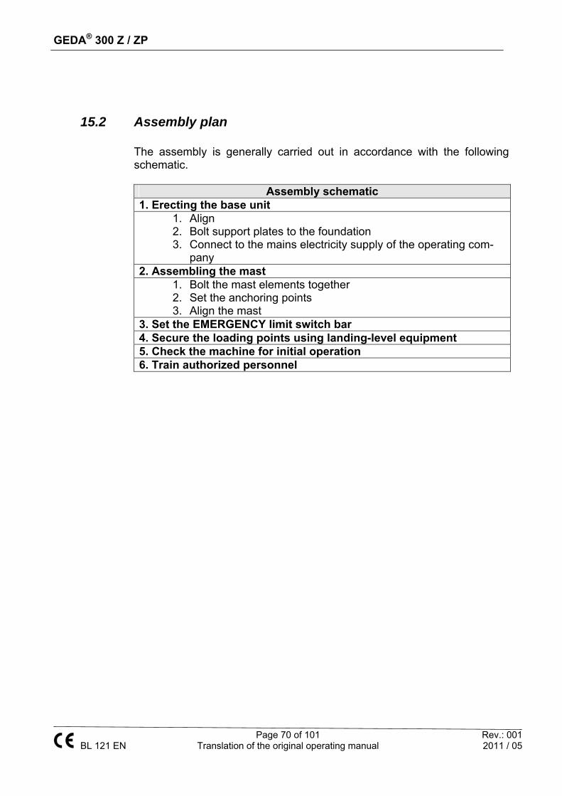
GEDA® 300 Z / ZP
Page 70 of 101 Rev.: 001 BL 121 EN Translation of the original operating manual 2011 / 05
15.2 Assembly plan The assembly is generally carried out in accordance with the following schematic.
Assembly schematic
1. Erecting the base unit 1. Align 2. Bolt support plates to the foundation 3. Connect to the mains electricity supply of the operating com-
pany 2. Assembling the mast
1. Bolt the mast elements together 2. Set the anchoring points 3. Align the mast
3. Set the EMERGENCY limit switch bar 4. Secure the loading points using landing-level equipment 5. Check the machine for initial operation 6. Train authorized personnel

GEDA® 300 Z / ZP
Page 71 of 101 Rev.: 001 BL 121 EN Translation of the original operating manual 2011 / 05
15.3 Assembling the base unit The base unit must be aligned horizontally and at right-angles to the building / scaffold-ing.
The introduction of forces into the foundation solely takes place via load-distributing supports (area min. = 0.25 m²).
Stand the base unit on load-distributing supports and align it with the support plates.
15.4 Mounting the first mast tie Mount the first mast tie at a height of approx. 4 m. Ensure at least 50 cm safety dis-
tance to the car.
After assembling the mast tie check the alignment of the base mast with a spirit lev-el.
WARNING
Danger to life caused by breakage or dislocation of the support plates.
The support plates must not carry any load, they serve the sole pur-pose of adjusting the base unit. Secure at least two support plates with screws against dislocating. Should this not be possible, the first mast tie must be mounted at a height of one meter. Once the base unit has been assembled you should check whether it stands securely and can be used by personnel to assemble the mast. For this purpose perform a test run with an empty car.
WARNING
Danger to life caused by mast breakage and dropping of the car.
The load capacity has been reduced to max. 300 kg:
- as long as no second mast tie has been mounted or - by travelling along the cantilevered mast section (max. 5.5 m upper
edge of trolley to mast fastening).

GEDA® 300 Z / ZP
Page 72 of 101 Rev.: 001 BL 121 EN Translation of the original operating manual 2011 / 05
15.5 Transport through narrow spaces For transport through narrow spaces (e.g. through doors etc.), the base assembly of the car can be folded up. Dimensions with base assembly folded up Width
= 0.87 m
Height (without assembly bridge)
= 2.05 m
Height with protective buffers dismantled (without assembly bridge)
= 1.97 m
Height (with assembly bridge)
= 2.30 m

GEDA® 300 Z / ZP
Page 73 of 101 Rev.: 001 BL 121 EN Translation of the original operating manual 2011 / 05
15.5.1 Dismantling the accesses
Loosen plug-in connections (1) of the accesses (A-C) on the base assembly.
If necessary label plug-in connections (1) to prevent any mix-up.
Loosen the bolts (2) of the frame at the access (A-C) and C and unscrew approx. 10 mm ( = 8 mm).
IMPORTANT
For access C also loosen the bolt (5) from the platform post (6).
Release and remove ac-cesses.
WARNING:
Unfastening the frame inhibits the protective function of the ac-cesses. Check the access bolts after each installation.
1
B
C
A
2
2
5
6

GEDA® 300 Z / ZP
Page 74 of 101 Rev.: 001 BL 121 EN Translation of the original operating manual 2011 / 05
15.5.2 Dismantling the front wall
Loosen both bolts (10) on the front wall (9).
Raise and remove the front wall from the base assem-bly.
15.5.3 Folding up the car
Remove sprint cotter pin (1).
Remove locking pin (2).
Fold up base assembly (3) and secure (rope, belt, etc.).
9
10
2 1
3

GEDA® 300 Z / ZP
Page 75 of 101 Rev.: 001 BL 121 EN Translation of the original operating manual 2011 / 05
15.5.4 Remove protective buffers
NOTE If the height needs to be further reduced, the protective buffers can be removed and subsequently the base unit can be carefully lowered onto the frame. Loosen the buffer bolt. Re-
move buffers. Slowly lower the base unit
onto the frame.
15.5.5 Unscrew foot section
Loosen the three bolts (1) on the front-side foot sec-tion (2).
Remove foot section. Use pallet truck to transport
base unit to the assembly location.
WARNING Only use a pallet truck with ade-quate stability and brake. Carry out transportation over inclines with the utmost care.
15.5.6 Installation at the assembly location Installation at the assembly location is always carried out in reverse order to the dismantling.
15.5.7 Inspection after assembly Check locking pins. It is not possible to fold up the base as-
sembly. Check all plug-in connections are connected properly. Open and close all access points. Make sure there is no problem with the functioning and inter-
locking. When access ramp is opened, no travel command is possible.
12
1

GEDA® 300 Z / ZP
Page 76 of 101 Rev.: 001 BL 121 EN Translation of the original operating manual 2011 / 05
15.6 Assembly / anchoring of the mast Assembly and anchoring of the mast is generally performed from the car and the scaffolding. When assembling without scaffolding, a mast bracket is used for anchoring the mast to the building from the assembly bridge.
Load the car. Observe the max. payload. Close the loading ramp. Press the UP button. The platform stops automatically at the top end. Lower the assembly guard. Attach the mast section, tilt it up and
tighten it. Reattach the assembly guard.
Press the UP button and assemble fur-
ther mast sections. Press the DOWN button and fetch fur-
ther mast parts from the ground.
WARNING
Danger to life
Mast fixtures must be planned at the following distances.
First mast fixture at a height of 4 m.
Subsequent mast fixtures every 6 meters.
After assembling a mast fixture the mast must be correctly aligned by using a spirit level.
DANGER
Danger to life Crushing or amputation of limbs. Never reach into the travel path of the machine during operation.

GEDA® 300 Z / ZP
Page 77 of 101 Rev.: 001 BL 121 EN Translation of the original operating manual 2011 / 05
15.6.1 Assembling the mast fixture To assemble the mast fixtures travel up to a point where these can easily mounted. The minimum distance to the assembly bridge is 5 cm.
Use extension tubes to increase the distance to the building. Choose the horizontal dis-tance from the wall as big as possible.
Fasten the mast fixture (1) from the front on the circular mast tube using a scaffolding coupling (2). (Tighten-ing torque 50 Nm).
Insert the telescopic tube (3). Close the scaffolding clamps (4), screw them together so that the tube can still be moved.
For adjusting the angle loosen the nuts below the scaffolding clamps (4) and move the clamps. Re-tighten the nuts.
In order to minimize wear on the gear racks, we recommend lubricating the gear racks each time a mast bracket is fitted.
WARNING
Danger of collision The free tube ends must not project beyond the mast cross-section / the travel path of the car.
14
3
2
Platform
1
2 3

GEDA® 300 Z / ZP
Page 78 of 101 Rev.: 001 BL 121 EN Translation of the original operating manual 2011 / 05
15.6.2 Trailing cable guide Trailing cable guides must be installed to ensure that the trailing cable runs freely into the cable box. The more sensitive the hoist location is to wind forces, the shorter the distances should be between trailing cable guides.
ATTENTION Attach the first trailing cable guide (1) at a distance of approx. 1 m from the up-per edge of the cable box. Assembly Mount trailing cable guide (1) at
right-angles on the circular mast tube and align centrally relative to the cable holder (2).
NOTE Rubber lug must point to the drive. ATTENTION Collision hazard with the sliding car-riage. Distance to the vertical cable
holder rectangular tube at least 10 mm.
1
10 mm
2

GEDA® 300 Z / ZP
Page 79 of 101 Rev.: 001 BL 121 EN Translation of the original operating manual 2011 / 05
15.6.3 Using the assembly bridge
The assembly bridge is solely intended for assembling the mast from the car. Prior to us-ing the car you must make sure that the assembly bridge safety latch has fully engaged (second tooth). With the assembly bridge unfolded the car can no longer be moved. Before assembling a mast fixture you should therefore position the car so that the assem-bly bridge can still be closed after assembly (1.6 m distance between mast fixture and car floor).
Opening the assembly bridge Loosen the safety latch, if necessary pull
the assembly bridge slightly inwards by the grip bar (2).
Unfold the assembly bridge completely us-ing the bracket (2).
Push the front wall outwards. Closing the assembly bridge Pull the front wall inwards by the bracket (2). Close the assembly bridge completely with the grip bar (the safety latch engages in the second tooth).

GEDA® 300 Z / ZP
Page 80 of 101 Rev.: 001 BL 121 EN Translation of the original operating manual 2011 / 05
15.6.4 Assembling the EMERGENCY limit switch bar
The EMERGENCY limit switch bar stops the car in case of a malfunction before it can exit the rack. Assemble the EMERGENCY limit switch bar so that the last mast fixture can be overtravelled by max. 3 m during operation. The minimum distance of the EMERGENCY limit switch bar to the top mast end must be at least 1.25 m.
1.1 LANDING-LEVEL limit switch bar The landing-level limit switch bar stops the car at the same level as the landing-level safety equip-ment. As a result, transfer between car and land-ing level is possible with no offset. Mount the landing-level limit switch bar so that the lower end of the landing-level limit switch bar is situated 33 cm above the level of the landing lev-el. Mount the landing-level limit switch bar between both rectangular tubes of the mast and secure to the circular mast tube with the welded coupling.
15.6.5 Securing loading and unloading points Fall protection systems must be provided at all loading and unloading points with heights above 2 m. Only fall protection systems allowing danger-free crossing may be used. GEDA lifts with type test certification must also only be used in combination with tested GEDA landing-level safety gates. For assembly of landing-level safety gates see corre-sponding instruction manual.

GEDA® 300 Z / ZP
Page 81 of 101 Rev.: 001 BL 121 EN Translation of the original operating manual 2011 / 05
15.6.6 Checks after assembly / checks prior to initial commissioning Perform checks as specified in the section Checks.
16 Disassembly Disassembly normally takes place in reverse order.
17 Disposing of the machine Dismantle the equipment properly at the end of its service life and dispose of in an environmentally friendly way according to national provisions. It is prohibited to recycle parts from a machine that is being disposed of for use in other machines, or to assemble such parts to produce a new ma-chine. Recommendation: Contact the manufacturer or commission a specialist company to handle disposal requirements in accordance with regulations.

GEDA® 300 Z / ZP
Page 82 of 101 Rev.: 001 BL 121 EN Translation of the original operating manual 2011 / 05
18 MAINTENANCE
18.1 Warnings and safety instructions to be complied with dur-ing maintenance / servicing
WARNING
The entire manual must be read for all service / repair work. Work is prohibited if the nature and scope of the work to be carried out is un-clear or the resulting hazards and measures which must be introduced to avert said hazards are unclear. All unclear issues must be resolved before starting work. All safety instructions must be complied with. The service intervals speci-fied must be adhered to.
DANGER
Danger to life Crushing or amputation of limbs. Never reach into the travel path of the machine during operation.
DANGER
Danger to life Falling tools / parts. Secure tools / parts against falling. Use the car roof.
DANGER
Danger to life Due to the machine being switched on during servicing / repair work or when there is a defect. Secure master switch with a padlock to prevent it from being switched on.
WARNING
Fall and trip hazard Look out for steps and objects on the ground when entering / exiting the car.

GEDA® 300 Z / ZP
Page 83 of 101 Rev.: 001 BL 121 EN Translation of the original operating manual 2011 / 05
18.2 Maintenance plan Tasks to be carried out Quarterly Every
year Function test of the car control X Function test of the car control X Check notices are present X Check the gear rack and drive pinion for wear X Check / refill the lubrication facility X Check the trailing cable for damage X Check collision grille and roof X Check the gear rack is positioned securely X Check attachment bolts on the access to the car (mounting frame) and tighten if necessary.
X
Check motor brakes (air gap and pad thickness) X Test / adjust the rescue equipment (release motor brakes) X Test the safety gear X Check track rollers on the sliding carriage X Protective earth testing in accordance with EN 60204, part 1 X Insulation test in accordance with EN 60204, part 1 X Visual check of all control devices, limit switches and lines X
DANGER
Electric shock Parts remain live even after actuating the EMERGENCY STOP or after switching off the machine at the master switch. Applies to all work on electrical parts. Disconnect mains supply upstream from the master switch.
WARNING
Danger to life Raised load. Do not stand under a suspended load. Do not stand on a suspended load. Only lift loads at the suspension points. Only use suitable hoisting gear.
WARNING
Danger to life Access only for authorised individuals. No access for unauthorised individuals.

GEDA® 300 Z / ZP
Page 84 of 101 Rev.: 001 BL 121 EN Translation of the original operating manual 2011 / 05
18.3 Inspections During the inspections, all safety-related characteristics of the machine are checked by means of appropriate procedures for condition, presence and function. Appropriate procedures are:
Visual inspections Function and efficacy testing Inspections using measuring and testing equipment
The scope, type and schedule of each inspection, and the persons author-ised to carry out the inspection should be specified by the operating com-pany.
Inspections plan
Inspection by a trained person
Inspection by a qualified per-son
Inspection by an accredited inspection body
(recurring inspection) Simple visual and functional checks with just a few inspection steps and simple evaluation
For systems that are subject to scheduled monitoring Inspection according to national regulations
Inspection by a qualified person
Inspection due to specific incidents / damaging influences,
such as Inspections according to maintenance plan
Natural phenomena:
Lightning
Storm
Flooding
Cold > −20 °C
See relevant section
Accidents:
Collision
Overturning
Crash
Changes / modifications:
Drive replacement
Safety gear replacement
Changes to the control electronics
Replacement of control and protection equipment
Replacement of electrical power cables
Installation:
For first start-up At a new location
Exposure to harmful substances
Corrosive media Contaminations of unknown origin
Visual inspections must always be carried out before function tests. Any defects identified must be reported immediately to a superior and rectified. Operation is prohibited until the defects are rectified. Defects must only be rectified by qualified specialists who are authorised to do so.

GEDA® 300 Z / ZP
Page 85 of 101 Rev.: 001 BL 121 EN Translation of the original operating manual 2011 / 05
Documenting the results The operating company must document the results of inspections. The documentation must be kept for a reasonable period of time – however at least for the entire lifetime of the machine. Proof of performance of the last inspection must be attached to the machine.
18.4 Visual inspections
Entire machine Damaged load-bearing elements / deformations.
Travel path of the machine clear.
Loose or fallen parts.
Damage to the car.
Oil / grease leaks.
Discolourations and soiling, corrosion, cracks.
Operation control light is on.
Warning and instruction notices All present and legible.
Safety equipment
All present.
Functional.
No tampering.
Switch cabinets Burnt / scorched areas.
Discolourations.
Moisture.

GEDA® 300 Z / ZP
Page 86 of 101 Rev.: 001 BL 121 EN Translation of the original operating manual 2011 / 05
18.4.1 Test run with an empty car
Unusual odours, noises or vibrations.
Oil / grease leaks.
Run car to its maximum height.
Stop the car at the correct position.
Travel further upwards not possible.
Run car down to ground station.
Stop the car at 2 m height, audible warning signal, travelling further towards the ground station only possible in dead man's mode.
Stop the car at the correct position.
Travel further downwards not possible.
18.4.2 Test run by platform operator / person authorised to carry out tests and inspections
ATTENTION
No one else is allowed to be in the car.
Move to each stop position.
Stop the car inside the tolerance range max. ± 2 cm.
Door of car and landing-level gate functional.

GEDA® 300 Z / ZP
Page 87 of 101 Rev.: 001 BL 121 EN Translation of the original operating manual 2011 / 05
18.5 Refilling and inspection jobs
18.5.1 Lubrication device
Fill up using the nipple Place the grease gun onto the nipple
(1).
(Underside of the reservoir)
Fill reservoir to the “MAX” mark.
NOTE
It may be useful to fold up the lubrication device in order to carry out maintenance on the safety gear.
Loosen bolt (2). Fully loosen and remove bolt (3).
Fold up the lubrication device using the holder.
Quick-filling with a filling gun Remove the cap from the filling
port (2).
Insert the grease gun up to the stop point inside the filling port.
Fill reservoir to the “MAX” mark.
Bleed the lubrication device If the limit switch is defective, the lubrication device will run completely empty and must be bled after the limit switch has been repaired / replaced. Place the grease gun onto the nipple (1).
Fill up to 4 cm above the “MIN” mark.
Remove the lubrication hose from the pump housing.
Remove the pump element or locking screw (M20x1.5) and keep open until bubble-free grease is discharged.
Re-screw the pump element or locking screw.
Trigger the lubricating pulse until lubricant runs out without air bubbles.
Reconnect the lubricating hose.
CAUTION Do not use any grease with solid lubricants. The lubrication device may become damaged.
3
3
1
2

GEDA® 300 Z / ZP
Page 88 of 101 Rev.: 001 BL 121 EN Translation of the original operating manual 2011 / 05
18.6 Checking for wear
18.6.1 Drive pinion Number of teeth = 14 Module m = 6 Wear limit Dimension X min. Dimension X normal 28,15 mm 28,85 mm Measure dimension X on each pair of teeth
18.6.2 Gear rack Gear rack dimension X1 = 50 mm Wear limit X 2 min. X2 new 53,50 mm 54,60 mm Gauging pin: 12 mm (+0.0 / −0.11 mm)
Check that all gear racks are positioned securely. If necessary tighten gear racks with 178 Nm.
WARNING
Danger of injury from components failing Parts must be replaced immediately if the specified wear limits are exceeded. Machine operation is prohibited until the parts have been replaced. All parts must also be checked for damage (deformation, cracks, cavities, etc.).

GEDA® 300 Z / ZP
Page 89 of 101 Rev.: 001 BL 121 EN Translation of the original operating manual 2011 / 05
18.6.3 Tracks rollers Track roller (white) Item-No. 13060 Wear limit (diameter) Ø min. Ø normal 77 mm 78-0.30 mm Also check the play and condition of the bearing. There must be a circlip.
Track roller with chamfer (white) Item-No. 18013 Wear limit (diameter) Ø min. Ø normal 77 mm 78-0.30 mm Also check the play and condition of the bearing. There must be a circlip.
Track roller (black) Item-No. 19983 Wear limit (diameter) Ø min. Ø normal 76 mm 77-0.30 mm Also check the play and condition of the bearing. There must be a circlip.
Change the track roller.
DANGER
Danger to life Falling tools / parts. Secure tools / parts against falling. Use the car roof.

GEDA® 300 Z / ZP
Page 90 of 101 Rev.: 001 BL 121 EN Translation of the original operating manual 2011 / 05
18.6.4 Motor brake Brake pad wear limits min. 11.5 mm Air-gap wear limit max. nominal 0,8 mm 0,3 mm
1 = Motor bearing plate, 2 = Solenoid, 3 = Anchor plate, 4 = Brake disc, 5 = Compression springs, 6 = Banjo bolts, 7 = Hexagon screws, 8 = Drivers, 9 = adjusting ring, 10 = manual release Air gap must be the same at each position. Always check the air gap at several positions.
In addition to this information, you must observe the information in the manu-facturer's manual. Non-compliance releases GEDA from any liability.
Switch off motor power supply.
Unscrew manual release bolts.
Loosen the bolt and remove the fan cover.
Remove the cable.
Pull dust protection ring out of the SLOT in the magnetic body and put over the bearing plate.
Remove dust with compressed air.
Loosen bolts and replace with new bolts.
Screw banjo bolts into the magnetic body to achieve the specified dis-tance.
Tighten bolts with a torque of 25 Nm.
Check the air gap with a caliper.
Check banjo bolts for secure seating.
Assemble in reverse order.
Carry out function test.

GEDA® 300 Z / ZP
Page 91 of 101 Rev.: 001 BL 121 EN Translation of the original operating manual 2011 / 05
18.7 Function tests
18.7.1 Safety gear The drop test is only permitted
When no one is in the car or in the travel section.
When the car is not loaded.
When there are no objects in the travel path.
When the drop test is activated from a safe distance.
Execution
WARNING
Risk of injury The drop test may only be carried out by a qualified person, spe-cifically appointed by the operating company who, based on his or her training, knowledge and practical experience, can evaluate the risks and assess the safe condition of the safety gear.
Remove dummy plug (1).
Insert the safety gear control (2).
1
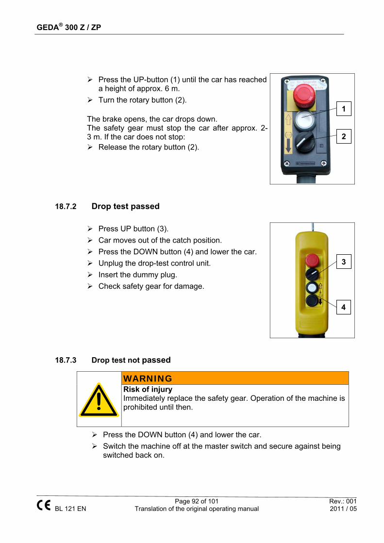
GEDA® 300 Z / ZP
Page 92 of 101 Rev.: 001 BL 121 EN Translation of the original operating manual 2011 / 05
18.7.2 Drop test passed
18.7.3 Drop test not passed
Press the DOWN button (4) and lower the car.
Switch the machine off at the master switch and secure against being switched back on.
Press the UP-button (1) until the car has reached a height of approx. 6 m.
Turn the rotary button (2).
The brake opens, the car drops down. The safety gear must stop the car after approx. 2-3 m. If the car does not stop: Release the rotary button (2).
Press UP button (3).
Car moves out of the catch position.
Press the DOWN button (4) and lower the car.
Unplug the drop-test control unit.
Insert the dummy plug.
Check safety gear for damage.
WARNING
Risk of injury Immediately replace the safety gear. Operation of the machine is prohibited until then.
2
1
3
4

GEDA® 300 Z / ZP
Page 93 of 101 Rev.: 001 BL 121 EN Translation of the original operating manual 2011 / 05
18.7.4 Check safety gear for damage If any damage is identified on the safety gear, the safety gear must be re-placed immediately. Machine operation is prohibited until it is repaired.
18.7.5 Safety gear replacement GEDA safety gear must be replaced with new GEDA safety gear (safety gear exchange units) after 5 years at the latest. The obligation to replace safety gear applies to both material hoists and personnel hoists.
WARNING
Risk of injury The safety gear must be inspected every 5 years by the manu-facturer. Repairs must only be carried out by the manufacturer.
Turn the master switch to the OFF position.
Secure against being switched on.
Loosen nut (1).
Remove protective cover (2).
Test brake pads for damage.
Test flyweights for ease of movement.
Condition of welded seams.
Condition of springs.
Corrosion / deformation.
Put back protective cover.
Mount protective cover (2) in such a way that switch tag (3) engages in the slot on the protec-tive cover. (Alternatively, turn the protective cov-er anti-clockwise until the switch tag (3) engages in the slot on the protective cover.)
Tighten nut (1).
1
3
2

GEDA® 300 Z / ZP
Page 94 of 101 Rev.: 001 BL 121 EN Translation of the original operating manual 2011 / 05
18.8 Fault table
Fault Cause Remedial action Green control light off Master switch off
Lamp bulb defective Phase failure Incorrect phase sequence Travelling cable plugged in Fuses OK Key switch for car control to OFF Safety gear triggered Distance of the proximity switch to monitor the racks too big
Turn on master switch Change bulb Measure the phases Correct the phase sequence on the phase sequence monitor Plug in the travelling cable Control / correction Turn key switch to “ON” Test and if necessary re-place Check the distance and cor-rect it if necessary (correct = 5-7 mm)
Red control light on Overload protection has trig-gered
Reduce the load
Motors do not generate full power
Voltage drop of more than 10%
Select supply cable with larger cross section
Car travels too high Top landing-level limit switch defective Fault in the electrical system
Test / replace top landing-level limit switch Test system
Car travels too low Fault in the electrical system Brake's air gap is too large
Test system Adjust air gap
WARNING
Only have troubleshooting and fault elimination carried out by authorised personnel trained especially for this kind of work. In the following table you will find potential faults and the appropriate remedial action.

GEDA® 300 Z / ZP
Page 95 of 101 Rev.: 001 BL 121 EN Translation of the original operating manual 2011 / 05
19 Documenting the checks
Documentation for a regular check according to the service schedule extraordinary check after unusual events
Name: Year of manufacture:
Serial number: Fabrication number:
The machine underwent a check on______________. As a result no the following
defects were recorded:
Scope of inspection:
Outstanding part checks:
Continued operation is: prohibited permitted
Follow up inspection is necessary not necessary
Place, date Signature (Technical expert / qualified person*)
*Name of qualified person
Operating company: Address:
Operating company:
Faults acknowledged:
Defects rectified:
Stamp Inspector

GEDA® 300 Z / ZP
Page 96 of 101 Rev.: 001 BL 121 EN Translation of the original operating manual 2011 / 05
Documentation for a regular check according to the service schedule extraordinary check after unusual events
Name: Year of manufacture:
Serial number: Fabrication number:
The machine underwent a check on______________. As a result no the following
defects were recorded:
Scope of inspection:
Outstanding part checks:
Continued operation is: prohibited permitted
Follow up inspection is necessary not necessary
Place, date Signature (Technical expert / qualified person*)
*Name of qualified person
Operating company: Address:
Operating company:
Defects acknowledged:
Defects rectified:
Stamp Inspector

GEDA® 300 Z / ZP
Page 97 of 101 Rev.: 001 BL 121 EN Translation of the original operating manual 2011 / 05
Documentation for a regular check according to the service schedule extraordinary check after unusual events
Name: Year of manufacture:
Serial number: Fabrication number:
The machine underwent a check on______________. As a result no the following
defects were recorded:
Scope of inspection:
Outstanding part checks:
Continued operation is: prohibited permitted
Follow up inspection is necessary not necessary
Place, date Signature (Technical expert / qualified person*)
*Name of qualified person
Operating company: Address:
Operating company:
Defects acknowledged:
Defects rectified:
Stamp Inspector

GEDA® 300 Z / ZP
Page 98 of 101 Rev.: 001 BL 121 EN Translation of the original operating manual 2011 / 05
Documentation for a regular check according to the service schedule extraordinary check after unusual events
Name: Year of manufacture:
Serial number: Fabrication number:
The machine underwent a check on______________. As a result no the following
defects were recorded:
Scope of inspection:
Outstanding part checks:
Continued operation is: prohibited permitted
Follow up inspection is necessary not necessary
Place, date Signature (Technical expert / qualified person*)
*Name of qualified person
Operating company: Address:
Operating company:
Defects acknowledged:
Defects rectified:
Stamp Inspector

GEDA® 300 Z / ZP
Page 99 of 101 Rev.: 001 BL 121 EN Translation of the original operating manual 2011 / 05
Documentation for a regular check according to the service schedule extraordinary check after unusual events
Name: Year of manufacture:
Serial number: Fabrication number:
The machine underwent a check on______________. As a result no the following
defects were recorded:
Scope of inspection:
Outstanding part checks:
Continued operation is: prohibited permitted
Follow up inspection is necessary not necessary
Place, date Signature (Technical expert / qualified person*)
*Name of qualified person
Operating company: Address:
Operating company:
Defects acknowledged:
Defects rectified:
Stamp Inspector

GEDA® 300 Z / ZP
Page 100 of 101 Rev.: 001 BL 121 EN Translation of the original operating manual 2011 / 05
Space for notices
Notice entered Name: / Date Position

GEDA® 300 Z / ZP
Page 101 of 101 Rev.: 001 BL 121 EN Translation of the original operating manual 2011 / 05
Space for notices
Notice entered Name: / Date Position