Embed Size (px)
Citation preview

Construction
Electrician
2015

CONSTRUCTION ELECTRICIAN
RED SEAL OCCUPATIONAL
STANDARD

You can download this publication by going online: publicentre.esdc.gc.ca This document is available on demand in multiple formats by contacting 1 800 O-Canada (1-800-622-6232), teletypewriter (TTY), 1-800-926-9105. © Her Majesty the Queen in right of Canada, 2016 [email protected] PDF Cat. No.: Em15-3/1-2016E-PDF ISBN: 978-0-660-04592-4 ESDC Cat. No. : LM-600-02-16E


1 Red Seal Occupational Standard – Construction Electrician - 2015
FOREWORD
The Canadian Council of Directors of Apprenticeship (CCDA) recognizes this Red Seal Occupational Standard (RSOS) as the Red Seal standard for the Construction Electrician trade.
Background
The first National Conference on Apprenticeship in Trades and Industries, held in Ottawa in 1952, recommended that the federal government be requested to cooperate with provincial and territorial apprenticeship committees and officials in preparing analyses of a number of skilled occupations. Employment and Social Development Canada (ESDC) sponsors the Red Seal Program, which, under the guidance of the CCDA, develops a national occupational standard for each of the Red Seal trades.
Standards have the following objectives:
• to describe and group the tasks performed by skilled workers;
• to identify which tasks are performed in every province and territory;
• to develop instruments for use in the preparation of Interprovincial Red Seal Examinations and
assessment tools for apprenticeship and certification authorities;
• to develop common tools for apprenticeship on-the-job and technical training in Canada;
• to facilitate the mobility of apprentices and skilled workers in Canada;
• to supply employers, employees, associations, industries, training institutions and governments with analyses of occupations.
Any questions, comments, or suggestions for changes, corrections, or revisions to this standard or any of its related products may be forwarded to:
Trades and Apprenticeship Division Labour Market Integration Directorate Employment and Social Development Canada 140 Promenade du Portage, Phase IV, 5th Floor Gatineau, Quebec K1A 0J9 Email: [email protected]

2 Red Seal Occupational Standard – Construction Electrician - 2015
STRUCTURE OF THE OCCUPATIONAL STANDARD
To facilitate understanding of the occupation, this standard contains the following sections: Description of the Construction Electrician trade: An overview of the trade’s duties, work environment, job requirements, similar occupations and career progression Essential Skills Summary: An overview of how each of the 9 essential skills is applied in this trade Trends in the Construction Electrician trade: Some of the trends identified by industry as being the most important for workers in this trade Pie Chart: a graph which depicts the national percentages of exam questions assigned to the major work activities Task Matrix and Examination Weightings: a chart which outlines graphically the major work activities, tasks and sub tasks of this standard and their respective exam weightings Major Work Activity (MWA): the largest division within the standard that is comprised of a distinct set of trade activities
Task: distinct actions that describe the activities within a major work activity
Task Descriptor: a general description of the task
Industry Expected Performance: a description of the expectations regarding the level of performance of the task, including information related to specific codes, regulations and standards that must be observed
Sub-task: distinct actions that describe the activities within a task
Essential Skills: The most relevant essential skills for this sub-task

3 Red Seal Occupational Standard – Construction Electrician - 2015
Skills:
Performance Criteria: description of the activities that are done as the sub-task is performed Evidence of Attainment: proof that the activities of the sub-task meet the expected performance of a tradesperson who has reached journeyperson level
Knowledge:
Learning Outcomes: describes what should be learned relating to a sub-task while participating in technical or in-school training Learning Objectives: topics to be covered during technical or in-school training in order to meet the learning outcomes for the sub-task
Range Variables: elements that provide a more in-depth description of a term used in the performance criteria, evidence of attainment, learning outcomes, or learning objectives
Appendix A – Acronyms: a list of acronyms used in the standard with their full name Appendix B – Tools and Equipment: a non-exhaustive list of tools and equipment used in this trade Appendix C – Glossary: definitions or explanations of selected technical terms used in the standard

4 Red Seal Occupational Standard – Construction Electrician - 2015
ACKNOWLEDGEMENTS
The CCDA and ESDC wish to express sincere appreciation for the contribution of the many tradespersons, industrial establishments, professional associations, labour organizations, provincial and territorial government departments and agencies, and all others who contributed to this publication.
Acknowledgement is extended by ESDC and the CCDA to the National Industry Advisory Committee for this project, coordinated by the National Electrical Trade Council (NETCO).
Special thanks are offered to the following representatives who contributed greatly to the original draft of the standard and provided expert advice throughout its development:
Brian Bodnaruk Northwest Territories Richard Brown NETCO Roddie Burke Prince Edward Island Andy Cleven British Columbia & NETCO Peter Friesen Alberta Curtis Goodwin Nova Scotia Pierre Liberatore Quebec & NETCO Dale MacDonald Ontario Barnaby McHarg Nova Scotia Joe Mignon Saskatchewan Benji Morehouse New Brunswick Robert Nelson Canadian Standards Association (CSA) Peter Olders Ontario & NETCO Nelson Rogers Newfoundland and Labrador Perry Samagalski Manitoba Ashley Seamans New Brunswick Darcy Tangedal Alberta Robert Thompson Ontario Monty Wood British Columbia
This standard was prepared by the Labour Market Integration Directorate of ESDC. The coordinating, facilitating and processing of this analysis were undertaken by employees of the standards development team of the Trades and Apprenticeship Division and of Apprenticeship New Brunswick. The host jurisdiction of Nova Scotia also participated in the development of this standard.

5 Red Seal Occupational Standard – Construction Electrician - 2015
DESCRIPTION OF THE CONSTRUCTION ELECTRICIAN TRADE “Construction Electrician” is this trade’s official Red Seal occupational title approved by the CCDA. This standard covers tasks performed by a construction electrician whose occupational title has been identified by some provinces and territories of Canada under the following names:
NL NS PE NB QC ON MB SK AB BC NT YT NU
Construction Electrician
Electrician
Electrician (Construction)
Electrician Construction and Maintenance
Construction electricians plan, design, assemble, install, alter, repair, inspect, verify, commission, connect, operate, maintain and decommission electrical systems. Electrical systems provide heating, lighting, power, alarm, security, communication and control in residential, commercial, institutional, industrial, transportation and entertainment environments. Construction electricians may be self-employed or employed by electrical contractors, utilities, and operations and maintenance departments of various facilities and municipalities. Construction electricians must read and interpret electrical, mechanical, civil and architectural drawings and specifications such as electrical, building, fire, and jurisdictional codes to complete electrical installations. They use electrical test equipment and digital technology to ensure system safety, functionality and compatibility. Construction electricians require good communication skills to negotiate, coordinate and facilitate work with clients, co-workers, jurisdictional authorities and other trades. Organizational skills are required to successfully plan and execute their work. They also require strong analytical and problem-solving skills in order to read and interpret diagrams, drawings and specifications. They require mechanical aptitude to install, diagnose and repair systems and components. It is beneficial for construction electricians to have good vision, the ability to distinguish colours, manual dexterity and a willingness to keep up with new developments in the trade. With changing technologies, digital and computer skills are necessary to this trade for job performance, learning methods and updating skills. Their work may be performed indoors or outdoors, at heights, in confined spaces and in hazardous environments. They require stamina as construction electricians spend much of their time performing static and physical tasks such as climbing. Occupational risks include shocks, industrial diseases, arc flashes, falls and injury from repetitive motion, lifting and kneeling. This standard recognizes similarities or overlaps with the work of industrial electricians, powerline technicians, instrumentation and control technicians, and refrigeration and air conditioning mechanics. Construction electricians work with a wide variety of construction tradespeople, engineers and inspectors. Construction electricians play a crucial role as mentors and trainers to apprentices in the trade. They may also advance to positions such as foremen, instructors, project managers, superintendents, estimators, technicians, system designers, electrical inspectors or start their own contracting business. Construction electricians may enhance their skills in different fields such as restorative, service or retrofit work rather than new construction.
6 Red Seal Occupational Standard – Construction Electrician - 2015
ESSENTIAL SKILLS SUMMARY Essential skills are needed for work, learning and life. They provide the foundation for learning all other skills and enable people to evolve with their jobs and adapt to workplace change. Through extensive research, the Government of Canada and other national and international agencies have identified and validated nine essential skills. These skills are used in nearly every occupation and throughout daily life in different ways. A series of CCDA-endorsed tools have been developed to support apprentices in their training and to be better prepared for a career in the trades. The tools can be used independently or with the assistance of a tradesperson, trainer, employer, teacher or mentor to:
• understand how essential skills are used in the trades; • learn about individual essential skills strengths and areas for improvement; and • improve essential skills and increase success in an apprenticeship program.
The tools are available online or for order at: www.esdc.gc.ca/eng/jobs/les/profiles/index.shtml The application of these skills may be described throughout this document within the skills and knowledge which support each sub-task of the trade. The most important essential skills for each sub-task have also been identified. The following are summaries of the requirements in each of the essential skills, taken from the essential skills profile. A link to the complete essential skills profile can be found at www.red-seal.ca.
READING
Construction electricians read several types of documents such as purchase order agreements and instructions for installing systems and components. They also need to read and understand the Canadian Electrical Code (CEC), which contains legal and highly technical language. They also read other tradespersons’ plans and specifications to understand the sequences of installation and locations of apparatus.
DOCUMENT USE Construction electricians apply document use skills when they read, interpret and collate information from several documents such as plans, specifications, diagrams and schematics. They reference and interpret these documents when installing, assembling, diagnosing and repairing electrical components and systems. The translation of two-dimensional and three-dimensional drawings into three-dimensional applications also requires strong document use skills.
WRITING Writing skills are required for construction electricians to record information about their daily work, including hours worked, job locations and details of conversations about the job. They may also be required to record details on an incident or an accident report. They also make notations on as-built drawings to indicate changes from the original drawings, accurately describing the current installation. Labelling and identifying electrical systems also require this skill.

7 Red Seal Occupational Standard – Construction Electrician - 2015
ORAL COMMUNICATION Strong oral communication skills are needed for construction electricians as they often need to relay messages, give directions, coordinate tasks with co-workers and discuss electrical code requirements with safety or building inspectors. They also regularly interact with supervisors, engineers, owners, architects, inspectors and other tradespersons to solve technical problems, to discuss work progress, and to ensure that work can meet scheduling and code requirements. They also exchange opinions with co-workers regarding critical safety issues related to complex installations.
NUMERACY Construction electricians use their numeracy skills to size and place electrical systems and components, ensuring that installations meet electrical code requirements. They take measurements and perform complex calculations using principles of mathematics such as geometry and trigonometry. Construction electricians also use numeracy skills to design or modify electrical installations.
THINKING SKILLS Construction electricians use thinking skills when they plan their work in order to ensure efficient use of time and resources. These skills also entail resolving issues such as system routing, and equipment placement and interconnection taking into account client specifications and code requirements. Additionally, these skills are called upon when consulting with other experienced tradespersons, manufacturers’ representatives or engineers to solve technical problems.
WORKING WITH OTHERS Construction electricians often work with co-workers, other trades, supervisors, owner representatives, architects, engineers, inspectors and suppliers. They may be required to demonstrate how to perform a task to other workers, mentor and orient or train new employees. They also participate in discussions about work processes or product improvement.
DIGITAL TECHNOLOGY Construction electricians use different types of hand-held digital devices such as oscilloscopes, multimeters and Power Quality Analyzers (PQA) to aid in diagnosing system and component failure. They also use different types of software to interface with these devices. They use their computer skills to improve the efficiency of product research, communication, record keeping, job tracking and information exchange with co-workers, other trades, supervisors, owner representatives, architects, engineers, inspectors and suppliers.
CONTINUOUS LEARNING It is important for construction electricians to stay up-to-date with changing requirements of the electrical code or with changes in technology, such as computer controls. They must be adaptable to change to advance their skills and increase their knowledge. These learning skills are applied when attending classes offered through unions, employers and other groups.
8 Red Seal Occupational Standard – Construction Electrician - 2015
TRENDS IN THE CONSTRUCTION ELECTRICIAN TRADE
TECHNOLOGY There is an ongoing growth of new technologies that influence a number of areas of the industry. Some emerging technologies include solar power systems, wind power systems, smart buildings and smart grid. There is a growth of renewable and alternative energy technologies such as solar photovoltaic, wind, hydrokinetic, geothermal, and tidal power systems in Canada which opens additional employment opportunities for qualified construction electricians. The emergence of electric vehicles (EV) in the Canadian market means there is an accompanying need for electric vehicle charging stations. Construction electricians would be responsible for installing and maintaining these electric vehicle charging stations. In some jurisdictions, construction electricians are responsible for the installation and maintenance of communication systems such as voice, data, audio, video and signalling. These systems are constantly evolving. Construction electricians are starting to use three dimensional (3D) modelling and building information modelling (BIM) to facilitate construction methods such as interpreting and updating drawings. They are using mobile devices to receive specifications and other information and assist in diagnostic procedures.
TRAINING AND UPGRADING The combination of new opportunities for construction electricians, new technologies and specialized skills has significantly impacted the electrical industry and triggered the development and delivery of related training. For example, upgrading and training could include areas such as fiber optics, structured cabling, satellite integration, wireless and local area networks (LAN), wireless Internet Protocol (IP) based lighting and building automation, and renewable energies. More than ever, construction electricians need to constantly upgrade and acquire new skills either through formal training, manufacturers’ training or on-the-job training to stay current. In some parts of the industry, more and more variable frequency drives (VFD) are being installed. The VFDs along with other electronic components have the potential to create power quality problems. This requires electricians to become trained in the procedures for measuring electric power quality and the methods needed to monitor and improve the power quality. Even though it is sometimes more cost effective to replace rather than repair electronic parts, a greater knowledge of electronic systems is still required to work with more complex electrical systems such as solid-state or computer-controlled.
SAFETY AND ENVIRONMENTAL CONSIDERATIONS Safety standards continue to be emphasized and recognized in all aspects of the trade. Safety training is branching out to include areas such as arc flash, high voltage, working at heights and supervision. Incidents of serious injury and death of electrical workers underlines the dangerous nature of the work that electricians may be engaged in and that electricians have a shared responsibility to implement safety training and follow safe work procedures. Electricians have to use their expertise on the worksite to assess risks, manage hazards and report issues as they arise. The electrical industry in Canada is moving towards efficient and environmentally friendly construction techniques and energy saving devices such as light emitting diode (LED) lighting, automated lighting control and variable speed drives. Additionally, Leadership in Energy and Environmental Design (LEED) is a growing trend for building construction.
9 Red Seal Occupational Standard – Construction Electrician - 2015
LANGUAGE REQUIREMENTS
It is expected that journeypersons are able to understand and communicate in either English or French, which are Canada’s official languages. English or French are the common language of business as well as language of instruction in apprenticeship programs.

10 Red Seal Occupational Standard – Construction Electrician - 2015
PIE CHART OF RED SEAL EXAMINATION WEIGHTINGS
MWA A PERFORMS COMMON OCCUPATIONAL SKILLS 11% MWA B INSTALLS, SERVICES AND MAINTAINS GENERATING, DISTRIBUTION
AND SERVICE SYSTEMS 29%
MWA C INSTALLS, SERVICES AND MAINTAINS WIRING SYSTEMS 30% MWA D INSTALLS, SERVICES AND MAINTAINS MOTORS AND CONTROL
SYSTEMS 20%
MWA E INSTALLS, SERVICES AND MAINTAINS SIGNALLING AND COMMUNICATION SYSTEMS
10%
This pie chart represents a breakdown of the interprovincial Red Seal examination. Percentages are based on the collective input from workers from the trade from across Canada. The Task Matrix on the next pages indicates the breakdown of tasks and sub-tasks within each Major Work Activity and the breakdown of questions assigned to the Tasks. The Interprovincial examination for this trade has 100 questions.
A 11%
B 29%
C 30%
D 20%
E 10%

11 Red Seal Occupational Standard – Construction Electrician - 2015
CONSTRUCTION ELECTRICIAN TASK MATRIX AND WEIGHTINGS
A - PERFORMS COMMON OCCUPATIONAL SKILLS 11%
Task A-1 Performs safety-related functions. 25%
A-1.01 Uses personal protective equipment (PPE) and safety equipment.
A-1.02 Maintains safe work environment.
A-1.03 Performs lock-out and tag-out procedures.
Task A-2 Uses tools and equipment. 17%
A-2.01 Uses common and specialty tools and equipment.
A-2.02 Uses access equipment.
A-2.03 Uses rigging, hoisting and lifting equipment.
Task A-3 Organizes work. 17%
A-3.01 Interprets plans, drawings and specifications.
A-3.02 Organizes materials and supplies.
A-3.03 Plans project tasks and procedures.
A-3.04 Prepares worksite. A-3.05 Finalizes required documentation.
Task A-4 Fabricates and installs support components. 18%
A-4.01 Fabricates support structures.
A-4.02 Installs brackets, hangers and fasteners.
A-4.03 Installs seismic restraint systems.
Task A-5 Commissions and decommissions electrical systems. 23%
A-5.01. Performs startup and shutdown procedures.
A-5.02 Performs commissioning and decommissioning of systems.
Task A-6 Uses communication and mentoring techniques. 0%
A-6.01 Uses communication techniques.
A-6.02 Uses mentoring techniques.

12 Red Seal Occupational Standard – Construction Electrician - 2015
B - INSTALLS, SERVICES AND MAINTAINS GENERATING, DISTRIBUTION AND SERVICE SYSTEMS
29%
Task B-7 Installs, services and maintains consumer/supply services and metering equipment. 18%
B-7.01 Installs single-phase consumer/supply services and metering equipment.
B-7.02 Installs three-phase consumer/supply services and metering equipment.
B-7.03 Performs servicing and maintenance of single-phase services and metering equipment.
B-7.04 Performs servicing and maintenance of three-phase services and metering equipment.
Task B-8 Installs, services and maintains protection devices. 17%
B-8.01 Installs overcurrent protection devices.
B-8.02 Installs ground fault, arc fault and surge protection devices.
B-8.03 Performs servicing and maintenance of protection devices.
Task B-9 Installs, services and maintains distribution equipment. 14%
B-9.01 Installs power distribution equipment.
B-9.02 Performs servicing and maintenance of power distribution equipment.
Task B-10 Installs, services and maintains power conditioning, uninterruptible power supply (UPS) and surge suppression systems. 5%
B-10.01 Installs power conditioning, UPS and surge suppression systems.
B-10.02 Performs servicing and maintenance of power conditioning, UPS and surge suppression systems.
Task B-11 Installs, services and maintains bonding and grounding protection systems. 16%
B-11.01 Installs grounding and bonding systems.
B-11.02 Installs ground fault systems.
B-11.03 Installs lightning protection systems.
B-11.04 Performs servicing and maintenance of bonding and grounding systems.
Task B-12 Installs, services and maintains power generation systems. 7%
B-12.01 Installs AC (alternating current) generating systems.
B-12.02 Performs servicing and maintenance of AC generating systems.
B-12.03 Installs DC (direct current) generating systems. (NOT COMMON CORE)
B-12.04 Performs servicing and maintenance of DC generating systems. (NOT COMMON CORE)

13 Red Seal Occupational Standard – Construction Electrician - 2015
Task B-13 Installs, services and maintains renewable energy systems. 6%
B-13.01 Installs renewable energy systems.
B-13.02 Performs servicing and maintenance of renewable energy systems.
Task B-14 Installs, services and maintains high voltage systems. 5%
B-14.01 Installs high voltage equipment.
B-14.02 Installs high voltage cables.
B-14.03 Performs servicing and maintenance of high voltage systems.
Task B-15 Installs, services and maintains transformers. 12%
B-15.01 Installs extra-low voltage transformers.
B-15.02 Installs low-voltage single-phase transformers.
B-15.03 Installs low-voltage three-phase transformers.
B-15.04 Installs high voltage transformers.
B-15.05 Performs servicing and maintenance of transformers.
14 Red Seal Occupational Standard – Construction Electrician - 2015
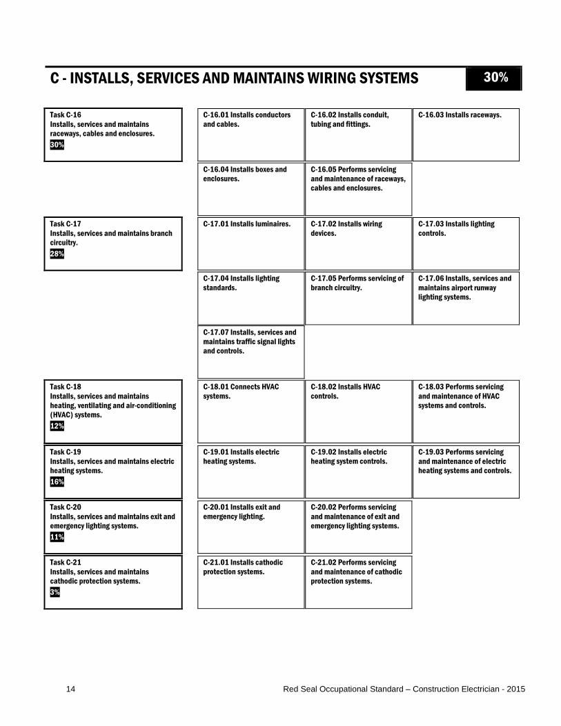
C - INSTALLS, SERVICES AND MAINTAINS WIRING SYSTEMS 30%
Task C-16 Installs, services and maintains raceways, cables and enclosures. 30%
C-16.01 Installs conductors and cables.
C-16.02 Installs conduit, tubing and fittings.
C-16.03 Installs raceways.
C-16.04 Installs boxes and enclosures.
C-16.05 Performs servicing and maintenance of raceways, cables and enclosures.
Task C-17 Installs, services and maintains branch circuitry. 28%
C-17.01 Installs luminaires. C-17.02 Installs wiring devices.
C-17.03 Installs lighting controls.
C-17.04 Installs lighting standards.
C-17.05 Performs servicing of branch circuitry.
C-17.06 Installs, services and maintains airport runway lighting systems.
C-17.07 Installs, services and maintains traffic signal lights and controls.
Task C-18 Installs, services and maintains heating, ventilating and air-conditioning (HVAC) systems. 12%
C-18.01 Connects HVAC systems.
C-18.02 Installs HVAC controls.
C-18.03 Performs servicing and maintenance of HVAC systems and controls.
Task C-19 Installs, services and maintains electric heating systems. 16%
C-19.01 Installs electric heating systems.
C-19.02 Installs electric heating system controls.
C-19.03 Performs servicing and maintenance of electric heating systems and controls.
Task C-20 Installs, services and maintains exit and emergency lighting systems. 11%
C-20.01 Installs exit and emergency lighting.
C-20.02 Performs servicing and maintenance of exit and emergency lighting systems.
Task C-21 Installs, services and maintains cathodic protection systems. 3%
C-21.01 Installs cathodic protection systems.
C-21.02 Performs servicing and maintenance of cathodic protection systems.
15 Red Seal Occupational Standard – Construction Electrician - 2015
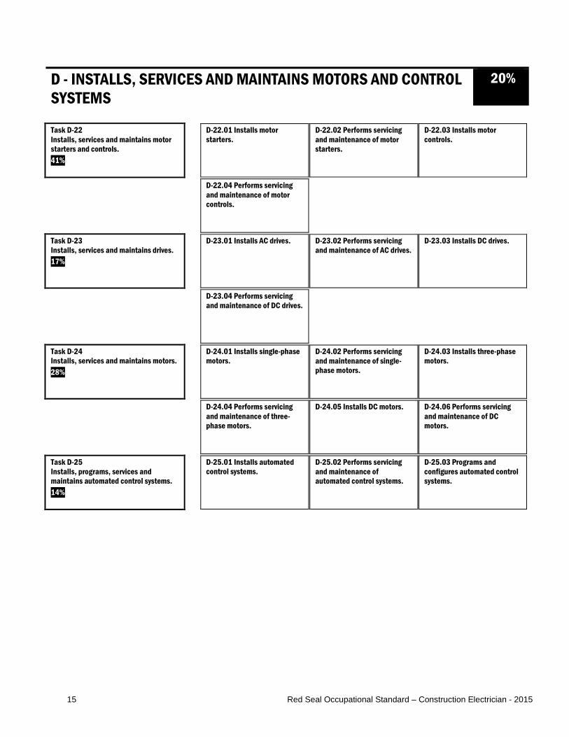
D - INSTALLS, SERVICES AND MAINTAINS MOTORS AND CONTROL SYSTEMS
20%
Task D-22 Installs, services and maintains motor starters and controls. 41%
D-22.01 Installs motor starters.
D-22.02 Performs servicing and maintenance of motor starters.
D-22.03 Installs motor controls.
D-22.04 Performs servicing and maintenance of motor controls.
Task D-23 Installs, services and maintains drives. 17%
D-23.01 Installs AC drives. D-23.02 Performs servicing and maintenance of AC drives.
D-23.03 Installs DC drives.
D-23.04 Performs servicing and maintenance of DC drives.
Task D-24 Installs, services and maintains motors. 28%
D-24.01 Installs single-phase motors.
D-24.02 Performs servicing and maintenance of single-phase motors.
D-24.03 Installs three-phase motors.
D-24.04 Performs servicing and maintenance of three-phase motors.
D-24.05 Installs DC motors. D-24.06 Performs servicing and maintenance of DC motors.
Task D-25 Installs, programs, services and maintains automated control systems. 14%
D-25.01 Installs automated control systems.
D-25.02 Performs servicing and maintenance of automated control systems.
D-25.03 Programs and configures automated control systems.

16 Red Seal Occupational Standard – Construction Electrician - 2015
E - INSTALLS, SERVICES AND MAINTAINS SIGNALLING AND COMMUNICATION SYSTEMS
10%
Task E-26 Installs, services and maintains signaling systems. 47%
E-26.01 Installs fire alarm systems.
E-26.02 Performs servicing and maintenance of fire alarm systems.
E-26.03 Installs security and surveillance systems.
E-26.04 Performs servicing and maintenance of security and surveillance systems.
Task E-27 Installs, services and maintains communication systems. 26%
E-27.01 Installs voice/data/video (VDV) and community antenna television (CATV) systems.
E-27.02 Installs public address (PA) and intercom systems.
E-27.03 Installs nurse call systems.
E-27.04 Performs servicing and maintenance of communication systems.
Task E-28 Installs, services and maintains integrated control systems. 27%
E-28.01 Installs building automation systems.
E-28.02 Installs building control systems.
E-28.03 Performs servicing and maintenance of integrated control systems.

17 Red Seal Occupational Standard – Construction Electrician - 2015
MAJOR WORK ACTIVITY A
PERFORMS COMMON OCCUPATIONAL SKILLS Task A-1 Performs safety-related functions. TASK DESCRIPTOR Construction electricians are responsible for ensuring the safety of themselves and others in the work environment. They must follow company, client and jurisdictional regulations. It is critical that construction electricians be constantly aware of their surroundings and the hazards they may encounter. INDUSTRY EXPECTED PERFORMANCE The task must be performed according to the applicable jurisdictional codes and standards. All health and safety standards must be respected. Specific regulations and standards for this task include WHMIS, OH&S, Canadian Standards Association (CSA) Z460, Z462 and Z463, and client and company safety policy. Work should be done efficiently and at a high quality without material waste or harm to the environment. All requirements of the manufacturer, client specifications and the authority having jurisdiction (AHJ) must be met. At a journeyperson level of performance, all tasks must be done with minimal direction and supervision.
A-1.01 Uses personal protective equipment (PPE) and safety equipment. Essential Skills Thinking Skills, Document Use, Reading
NL NS PE NB QC ON MB SK AB BC NT YT NU
yes yes yes yes NV yes yes yes yes yes NV NV NV SKILLS
Performance Criteria Evidence of Attainment A-1.01.01P identify site hazards and regulations
requiring the use of PPE and safety equipment
site hazards are determined by site visits and by doing a pre-job analysis
A-1.01.02P select PPE and safety equipment PPE and safety equipment are selected to match tasks and hazardous situations
A-1.01.03P ensure fit of PPE for the application PPE are adjusted to provide maximum protection for the individual
18 Red Seal Occupational Standard – Construction Electrician - 2015
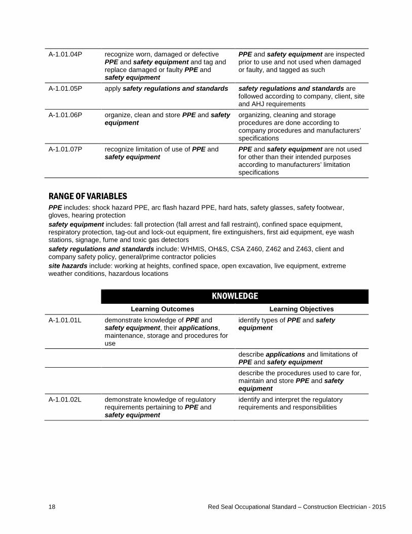
A-1.01.04P recognize worn, damaged or defective PPE and safety equipment and tag and replace damaged or faulty PPE and safety equipment
PPE and safety equipment are inspected prior to use and not used when damaged or faulty, and tagged as such
A-1.01.05P apply safety regulations and standards safety regulations and standards are followed according to company, client, site and AHJ requirements
A-1.01.06P organize, clean and store PPE and safety equipment
organizing, cleaning and storage procedures are done according to company procedures and manufacturers’ specifications
A-1.01.07P recognize limitation of use of PPE and safety equipment
PPE and safety equipment are not used for other than their intended purposes according to manufacturers’ limitation specifications
RANGE OF VARIABLES PPE includes: shock hazard PPE, arc flash hazard PPE, hard hats, safety glasses, safety footwear, gloves, hearing protection safety equipment includes: fall protection (fall arrest and fall restraint), confined space equipment, respiratory protection, tag-out and lock-out equipment, fire extinguishers, first aid equipment, eye wash stations, signage, fume and toxic gas detectors safety regulations and standards include: WHMIS, OH&S, CSA Z460, Z462 and Z463, client and company safety policy, general/prime contractor policies site hazards include: working at heights, confined space, open excavation, live equipment, extreme weather conditions, hazardous locations KNOWLEDGE
Learning Outcomes Learning Objectives A-1.01.01L demonstrate knowledge of PPE and
safety equipment, their applications, maintenance, storage and procedures for use
identify types of PPE and safety equipment
describe applications and limitations of PPE and safety equipment
describe the procedures used to care for, maintain and store PPE and safety equipment
A-1.01.02L demonstrate knowledge of regulatory requirements pertaining to PPE and safety equipment
identify and interpret the regulatory requirements and responsibilities

19 Red Seal Occupational Standard – Construction Electrician - 2015
RANGE OF VARIABLES PPE includes: shock hazard PPE, arc flash hazard PPE, hard hats, safety glasses, safety footwear, gloves, hearing protection safety equipment includes: fall protection (fall arrest and fall restraint), confined space equipment, respiratory protection, tag-out and lock-out equipment, fire extinguishers, first aid equipment, eye wash stations, signage, fume and toxic gas detectors applications include: hazardous locations, height, confined space
A-1.02 Maintains safe work environment. Essential Skills Thinking Skills, Document Use, Reading
NL NS PE NB QC ON MB SK AB BC NT YT NU
yes yes yes yes NV yes yes yes yes yes NV NV NV SKILLS
Performance Criteria Evidence of Attainment A-1.02.01P perform housekeeping practices work area is clean and clutter-free A-1.02.02P identify, report and eliminate potential and
existing hazards hazards are identified and mitigated
A-1.02.03P set up barriers and signage to explain hazards
hazards are well marked by barriers and signage
A-1.02.04P store materials and equipment materials and equipment are stored in designated areas, according to WHMIS, client and company policies and practices, site-specific practices and AHJ
A-1.02.05P identify and respect physical limitations of self and others
identify physical limitations and work within them
A-1.02.06P set up and identify locations containing safety components
locations are identified with signage and on jobsite map
A-1.02.07P enforce safe work practices safe work practices are followed
RANGE OF VARIABLES hazards include: arc flashes, liquid spills (flammable, corrosive, toxic), electric shocks, designated substance (asbestos, mercury, lead, silica), open holes, confined space, fire, tripping hazards, overhead work, hazardous locations barriers and signage include: caution and danger tapes, fences, tags, signs safety components include: first aid kits, fire extinguishers, material safety data sheets (MSDS) , eye wash stations items include: inspections, potential hazards, safety meetings, injuries, training
20 Red Seal Occupational Standard – Construction Electrician - 2015
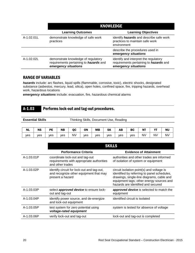
KNOWLEDGE Learning Outcomes Learning Objectives
A-1.02.01L demonstrate knowledge of safe work practices
identify hazards and describe safe work practices to maintain safe work environment
describe the procedures used in emergency situations
A-1.02.02L demonstrate knowledge of regulatory requirements pertaining to hazards and emergency situations
identify and interpret the regulatory requirements pertaining to hazards and emergency situations
RANGE OF VARIABLES hazards include: arc flashes, liquid spills (flammable, corrosive, toxic), electric shocks, designated substance (asbestos, mercury, lead, silica), open holes, confined space, fire, tripping hazards, overhead work, hazardous locations emergency situations include: evacuation, fire, hazardous chemical alarms
A-1.03 Performs lock-out and tag-out procedures. Essential Skills Thinking Skills, Document Use, Reading
NL NS PE NB QC ON MB SK AB BC NT YT NU
yes yes yes yes NV yes yes yes yes yes NV NV NV SKILLS
Performance Criteria Evidence of Attainment A-1.03.01P coordinate lock-out and tag-out
requirements with appropriate authorities and other trades
authorities and other trades are informed of isolation of system or equipment
A-1.03.02P identify circuit for lock-out and tag-out, and recognize other equipment that may present a hazard
circuit isolation point(s) and voltage is identified by referring to panel schedules, drawings, single-line diagrams, cable and equipment tags; other energy sources and hazards are identified and secured
A-1.03.03P select approved device to ensure lock-out and tag-out
approved device is selected to match the equipment
A-1.03.04P identify power source, and de-energize and lock-out equipment
identified circuit is isolated
A-1.03.05P test system for zero potential using voltage-rated equipment
system is tested for absence of voltage
A-1.03.06P verify lock-out and tag-out lock-out and tag-out is completed

21 Red Seal Occupational Standard – Construction Electrician - 2015
RANGE OF VARIABLES approved devices include: breaker lock, scissors, tag and arc flash protection equipment voltage-rated equipment include: voltmeters, ground straps, high voltage testers KNOWLEDGE
Learning Outcomes Learning Objectives A-1.03.01L demonstrate knowledge of lock-out and
tag-out procedures and legislation governing minimum standards
describe lock-out and tag-out procedures and legislation
A-1.03.02L demonstrate knowledge of safety checks of equipment
describe safety checks to be performed to ensure zero energy state
A-1.03.03L demonstrate knowledge of procedures for voltage testing
describe how to determine the testing equipment to be used is matched to the voltage and energy rating
22 Red Seal Occupational Standard – Construction Electrician - 2015
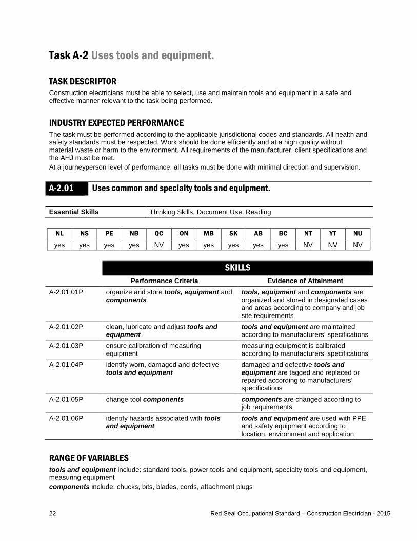
Task A-2 Uses tools and equipment. TASK DESCRIPTOR Construction electricians must be able to select, use and maintain tools and equipment in a safe and effective manner relevant to the task being performed. INDUSTRY EXPECTED PERFORMANCE The task must be performed according to the applicable jurisdictional codes and standards. All health and safety standards must be respected. Work should be done efficiently and at a high quality without material waste or harm to the environment. All requirements of the manufacturer, client specifications and the AHJ must be met. At a journeyperson level of performance, all tasks must be done with minimal direction and supervision.
A-2.01 Uses common and specialty tools and equipment. Essential Skills Thinking Skills, Document Use, Reading
NL NS PE NB QC ON MB SK AB BC NT YT NU
yes yes yes yes NV yes yes yes yes yes NV NV NV SKILLS
Performance Criteria Evidence of Attainment A-2.01.01P organize and store tools, equipment and
components tools, equipment and components are organized and stored in designated cases and areas according to company and job site requirements
A-2.01.02P clean, lubricate and adjust tools and equipment
tools and equipment are maintained according to manufacturers’ specifications
A-2.01.03P ensure calibration of measuring equipment
measuring equipment is calibrated according to manufacturers’ specifications
A-2.01.04P identify worn, damaged and defective tools and equipment
damaged and defective tools and equipment are tagged and replaced or repaired according to manufacturers’ specifications
A-2.01.05P change tool components components are changed according to job requirements
A-2.01.06P identify hazards associated with tools and equipment
tools and equipment are used with PPE and safety equipment according to location, environment and application
RANGE OF VARIABLES tools and equipment include: standard tools, power tools and equipment, specialty tools and equipment, measuring equipment components include: chucks, bits, blades, cords, attachment plugs
23 Red Seal Occupational Standard – Construction Electrician - 2015
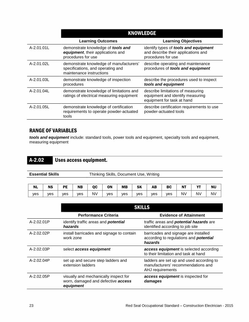
KNOWLEDGE Learning Outcomes Learning Objectives
A-2.01.01L demonstrate knowledge of tools and equipment, their applications and procedures for use
identify types of tools and equipment and describe their applications and procedures for use
A-2.01.02L demonstrate knowledge of manufacturers’ specifications, and operating and maintenance instructions
describe operating and maintenance procedures of tools and equipment
A-2.01.03L demonstrate knowledge of inspection procedures
describe the procedures used to inspect tools and equipment
A-2.01.04L demonstrate knowledge of limitations and ratings of electrical measuring equipment
describe limitations of measuring equipment and identify measuring equipment for task at hand
A-2.01.05L demonstrate knowledge of certification requirements to operate powder-actuated tools
describe certification requirements to use powder-actuated tools
RANGE OF VARIABLES tools and equipment include: standard tools, power tools and equipment, specialty tools and equipment, measuring equipment
A-2.02 Uses access equipment. Essential Skills Thinking Skills, Document Use, Writing
NL NS PE NB QC ON MB SK AB BC NT YT NU
yes yes yes yes NV yes yes yes yes yes NV NV NV SKILLS
Performance Criteria Evidence of Attainment A-2.02.01P identify traffic areas and potential
hazards traffic areas and potential hazards are identified according to job site
A-2.02.02P install barricades and signage to contain work zone
barricades and signage are installed according to regulations and potential hazards
A-2.02.03P select access equipment access equipment is selected according to their limitation and task at hand
A-2.02.04P set up and secure step ladders and extension ladders
ladders are set up and used according to manufacturers’ recommendations and AHJ requirements
A-2.02.05P visually and mechanically inspect for worn, damaged and defective access equipment
access equipment is inspected for damages
24 Red Seal Occupational Standard – Construction Electrician - 2015
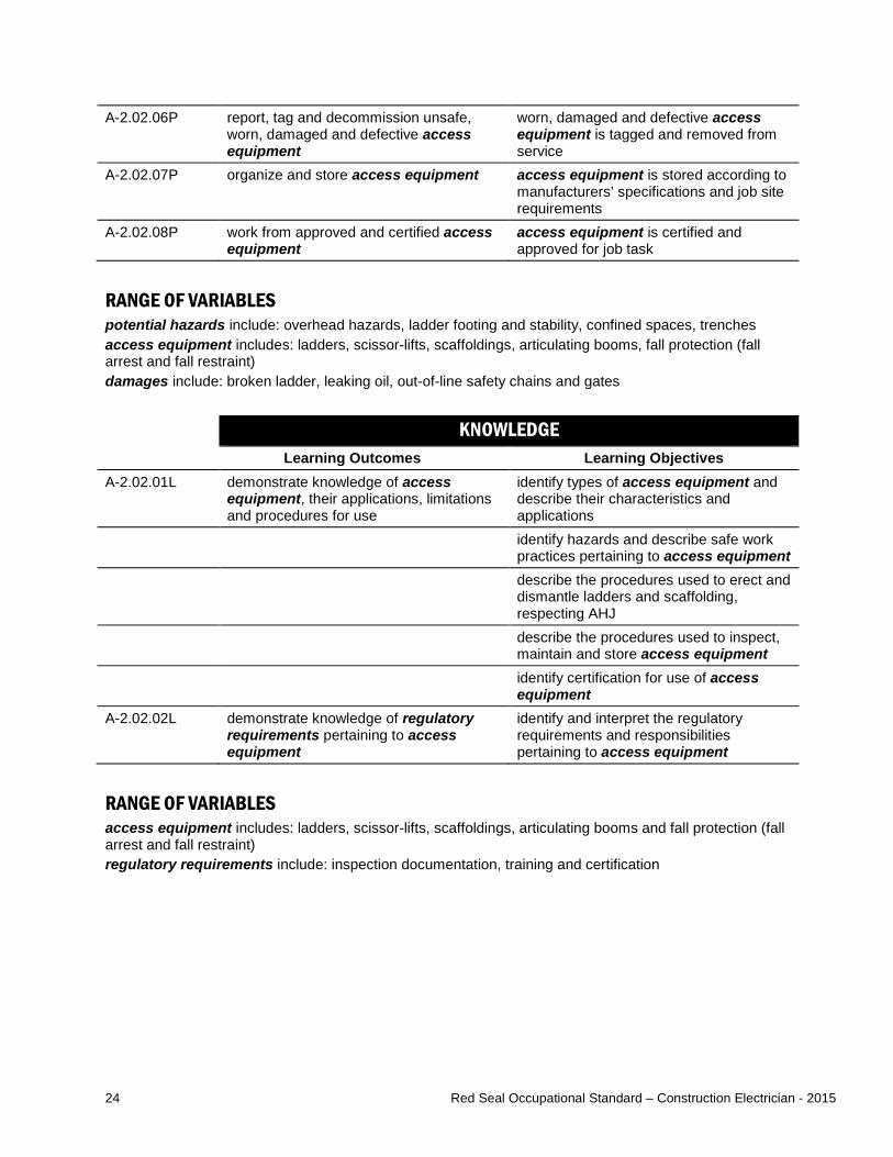
A-2.02.06P report, tag and decommission unsafe, worn, damaged and defective access equipment
worn, damaged and defective access equipment is tagged and removed from service
A-2.02.07P organize and store access equipment access equipment is stored according to manufacturers’ specifications and job site requirements
A-2.02.08P work from approved and certified access equipment
access equipment is certified and approved for job task
RANGE OF VARIABLES potential hazards include: overhead hazards, ladder footing and stability, confined spaces, trenches access equipment includes: ladders, scissor-lifts, scaffoldings, articulating booms, fall protection (fall arrest and fall restraint) damages include: broken ladder, leaking oil, out-of-line safety chains and gates KNOWLEDGE
Learning Outcomes Learning Objectives A-2.02.01L demonstrate knowledge of access
equipment, their applications, limitations and procedures for use
identify types of access equipment and describe their characteristics and applications
identify hazards and describe safe work practices pertaining to access equipment
describe the procedures used to erect and dismantle ladders and scaffolding, respecting AHJ
describe the procedures used to inspect, maintain and store access equipment
identify certification for use of access equipment
A-2.02.02L demonstrate knowledge of regulatory requirements pertaining to access equipment
identify and interpret the regulatory requirements and responsibilities pertaining to access equipment
RANGE OF VARIABLES access equipment includes: ladders, scissor-lifts, scaffoldings, articulating booms and fall protection (fall arrest and fall restraint) regulatory requirements include: inspection documentation, training and certification

25 Red Seal Occupational Standard – Construction Electrician - 2015
A-2.03 Uses rigging, hoisting and lifting equipment. Essential Skills Thinking Skills, Document Use, Numeracy
NL NS PE NB QC ON MB SK AB BC NT YT NU
yes yes yes yes NV yes yes yes yes yes NV NV NV SKILLS
Performance Criteria Evidence of Attainment A-2.03.01P identify traffic areas and potential
hazards traffic areas and potential hazards are identified according to job site
A-2.03.02P install barricades and signage to contain work zone
barricades and signage are installed according to regulations and potential hazards
A-2.03.03P select rigging, hoisting and lifting equipment
rigging, hoisting and lifting equipment is selected according to their limitation and task at hand
A-2.03.04P secure rigging, hoisting and lifting equipment
rigging, hoisting and lifting equipment is secured according to manufacturers and AHJ requirements
A-2.03.05P use and interpret hand and audible signals
hand and audible signals are used to direct load to intended position
A-2.03.06P ensure capacity of rigging, hoisting and lifting equipment
rigging, hoisting and lifting equipment loading capacity meets engineering and AHJ requirements
A-2.03.07P visually and mechanically inspect for worn, damaged and defective rigging, hoisting and lifting equipment
rigging, hoisting and lifting equipment is inspected for damages
A-2.03.08P report, tag and decommission unsafe, damaged and defective rigging, hoisting and lifting equipment
damaged and defective rigging, hoisting and lifting equipment is tagged and removed from service
A-2.03.09P secure load for application load is secured according to engineer and manufacturers’ specifications, AHJ requirements and company policy
A-2.03.10P clean, lubricate and store rigging, hoisting and lifting equipment
rigging, hoisting and lifting equipment is cleaned, lubricated and stored according to company procedures and manufacturers’ specifications
A-2.03.11P perform minor field maintenance on rigging, hoisting and lifting equipment
rigging, hoisting and lifting equipment is maintained according to manufacturers’ specifications
A-2.03.12P move load to final position load is moved to final position according to drawings and specifications

26 Red Seal Occupational Standard – Construction Electrician - 2015
RANGE OF VARIABLES potential hazards include: overhead hazards, dropped loads, damaged rigging hardware, congested worksites, confined spaces, trenches damages include: worn slings, worn shackles, missing or distorted safety catches, frayed ropes and slings, oil leaks KNOWLEDGE
Learning Outcomes Learning Objectives A-2.03.01L demonstrate knowledge of hoisting, lifting
and rigging equipment, their applications, limitations and procedures for use
identify types of rigging equipment and accessories and describe their applications and procedures for use
identify types of hoisting and lifting equipment and accessories and describe their applications and procedures for use
identify potential hazards and describe safe work practices pertaining to hoisting, lifting and rigging
describe the procedures used to inspect, maintain and store hoisting, lifting and rigging equipment
A-2.03.02L demonstrate knowledge of regulatory requirements pertaining to hoisting, lifting and rigging equipment
identify and interpret codes and regulations pertaining to hoisting, lifting and rigging
A-2.03.03L demonstrate knowledge of basic hoisting and lifting operations
identify types of knots, hitches, splices and bends and describe their applications and the procedures used to tie them
describe the considerations when rigging material/equipment for lifting
identify and describe procedures used to communicate during hoisting, lifting and rigging operations
RANGE OF VARIABLES potential hazards include: overhead hazards, dropped loads, damaged rigging hardware, congested worksites, confined spaces, trenches regulatory requirements include: inspection documentation, training, certification considerations include: load characteristics, working load limit (WLL), equipment and accessories, environmental factors, anchor points, sling angles procedures used to communicate include: hand signals, electronic communications, audible/visual

27 Red Seal Occupational Standard – Construction Electrician - 2015
Task A-3 Organizes work. TASK DESCRIPTOR Construction electricians organize projects in order to safely and efficiently use material, labour, tools and equipment. They interpret drawings, plans and specifications to identify required resources. Prior to starting they must plan their tasks, prepare the worksite and organize the materials and supplies needed. Construction electricians must document their work and prepare as-built drawings and operations and maintenance (O&M) manuals. INDUSTRY EXPECTED PERFORMANCE The task must be performed according to the applicable jurisdictional codes and standards. All health and safety standards must be respected. Work should be done efficiently and at a high quality without material waste or harm to the environment. All requirements of the manufacturer, client specifications and the AHJ must be met. At a journeyperson level of performance, all tasks must be done with minimal direction and supervision.
A-3.01 Interprets plans, drawings and specifications. Essential Skills Document Use, Reading, Numeracy
NL NS PE NB QC ON MB SK AB BC NT YT NU
yes yes yes yes NV yes yes yes yes yes NV NV NV SKILLS
Performance Criteria Evidence of Attainment A-3.01.01P identify symbols found on drawings and
specifications symbols are identified from legends, notes and specifications
A-3.01.02P scale dimensions to determine location of devices
location of devices is determined by making a measurement using scaling from drawings
A-3.01.03P locate and cross-reference information on plans, drawings, specifications and contract documents
installation information is obtained by interpreting plans, drawings, specifications and contract documents
A-3.01.04P visualize finished product based on information in plans, drawings and specifications
visualization is described to supervisor and confirmed as matching the job requirements
A-3.01.05P determine if plans, drawings, schematics and specifications are current
plans, drawings, schematics and specifications are compared with the existing installation

28 Red Seal Occupational Standard – Construction Electrician - 2015
KNOWLEDGE Learning Outcomes Learning Objectives
A-3.01.01L demonstrate knowledge of drawings, schematics and specifications and their applications
identify types of drawings, schematics and specifications, and describe their applications
identify documentation requirements for modifying drawings and specifications
describe the procedures used to document changes made to equipment and wiring
A-3.01.02L demonstrate knowledge of imperial and SI (système internationale) units in trade documentation
interpret imperial and SI units of measure used
A-3.01.02L demonstrate knowledge of interpreting and extracting information from drawings, schematics and specifications
interpret and extract information from drawings, schematics and specifications
explain how scaling is performed to position devices
RANGE OF VARIABLES drawings, schematics and specifications include: civil/site, architectural, mechanical, structural, electrical, shop, sketches, as-builts information includes: elevations, scales, legends, symbols and abbreviations, notes and specifications, addendums, Construction Specifications Canada (CSC) Specification Divisions 25, 26, 27 and 28
A-3.02 Organizes materials and supplies. Essential Skills Document Use, Thinking Skills, Numeracy
NL NS PE NB QC ON MB SK AB BC NT YT NU
yes yes yes yes NV yes yes yes yes yes NV NV NV SKILLS
Performance Criteria Evidence of Attainment A-3.02.01P identify and select materials and
supplies materials and supplies are selected according to drawings, specifications and CEC requirements
A-3.02.02P locate, order and schedule delivery of materials and supplies
materials and supplies are ordered and delivered according to criteria
A-3.02.03P load, unload and store materials and supplies
materials and supplies are loaded, unloaded and stored according to factors
A-3.02.04P perform material take-off to identify required materials and supplies
materials and supplies are identified according to drawings and specifications
29 Red Seal Occupational Standard – Construction Electrician - 2015
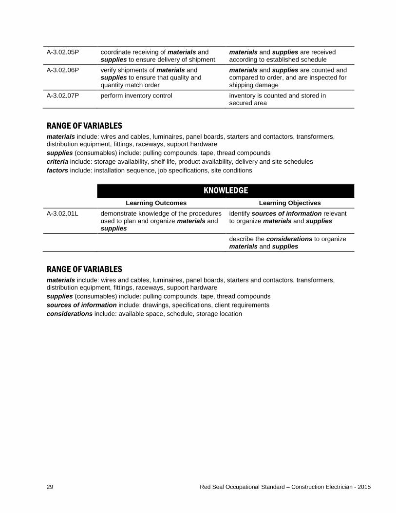
A-3.02.05P coordinate receiving of materials and supplies to ensure delivery of shipment
materials and supplies are received according to established schedule
A-3.02.06P verify shipments of materials and supplies to ensure that quality and quantity match order
materials and supplies are counted and compared to order, and are inspected for shipping damage
A-3.02.07P perform inventory control inventory is counted and stored in secured area
RANGE OF VARIABLES materials include: wires and cables, luminaires, panel boards, starters and contactors, transformers, distribution equipment, fittings, raceways, support hardware supplies (consumables) include: pulling compounds, tape, thread compounds criteria include: storage availability, shelf life, product availability, delivery and site schedules factors include: installation sequence, job specifications, site conditions KNOWLEDGE
Learning Outcomes Learning Objectives A-3.02.01L demonstrate knowledge of the procedures
used to plan and organize materials and supplies
identify sources of information relevant to organize materials and supplies
describe the considerations to organize materials and supplies
RANGE OF VARIABLES materials include: wires and cables, luminaires, panel boards, starters and contactors, transformers, distribution equipment, fittings, raceways, support hardware supplies (consumables) include: pulling compounds, tape, thread compounds sources of information include: drawings, specifications, client requirements considerations include: available space, schedule, storage location
30 Red Seal Occupational Standard – Construction Electrician - 2015
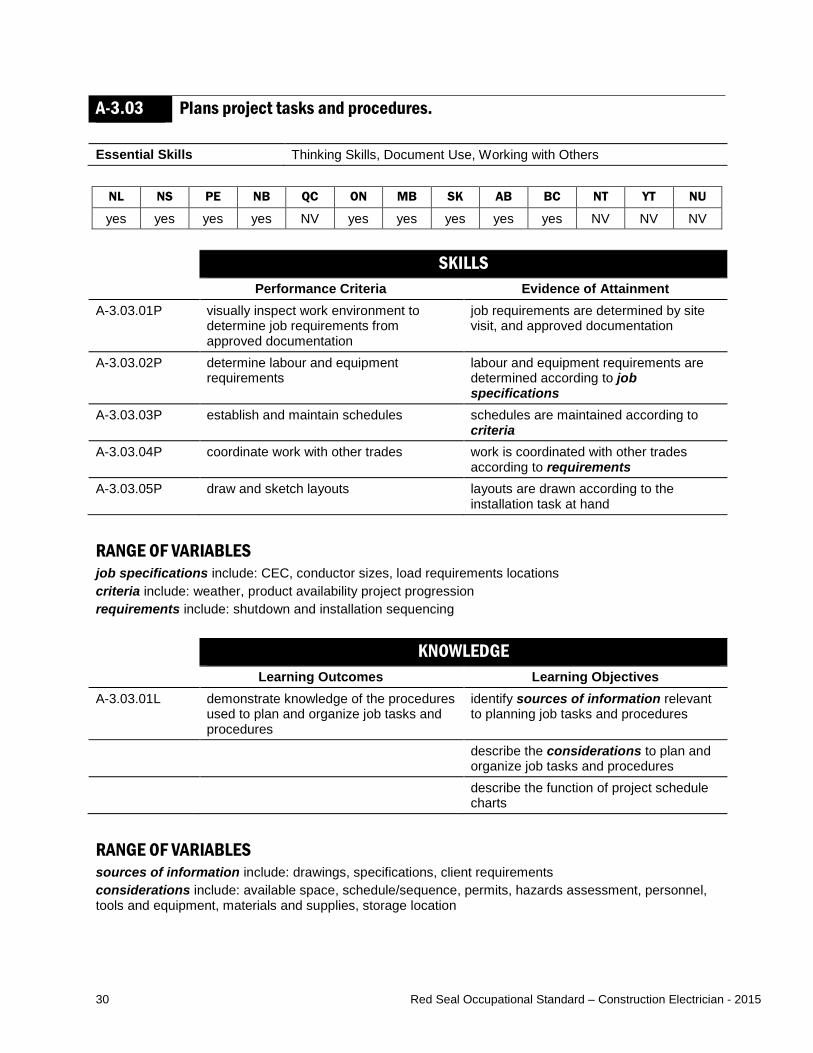
A-3.03 Plans project tasks and procedures. Essential Skills Thinking Skills, Document Use, Working with Others
NL NS PE NB QC ON MB SK AB BC NT YT NU
yes yes yes yes NV yes yes yes yes yes NV NV NV SKILLS
Performance Criteria Evidence of Attainment A-3.03.01P visually inspect work environment to
determine job requirements from approved documentation
job requirements are determined by site visit, and approved documentation
A-3.03.02P determine labour and equipment requirements
labour and equipment requirements are determined according to job specifications
A-3.03.03P establish and maintain schedules schedules are maintained according to criteria
A-3.03.04P coordinate work with other trades work is coordinated with other trades according to requirements
A-3.03.05P draw and sketch layouts layouts are drawn according to the installation task at hand
RANGE OF VARIABLES job specifications include: CEC, conductor sizes, load requirements locations criteria include: weather, product availability project progression requirements include: shutdown and installation sequencing
KNOWLEDGE Learning Outcomes Learning Objectives
A-3.03.01L demonstrate knowledge of the procedures used to plan and organize job tasks and procedures
identify sources of information relevant to planning job tasks and procedures
describe the considerations to plan and organize job tasks and procedures
describe the function of project schedule charts
RANGE OF VARIABLES sources of information include: drawings, specifications, client requirements considerations include: available space, schedule/sequence, permits, hazards assessment, personnel, tools and equipment, materials and supplies, storage location
31 Red Seal Occupational Standard – Construction Electrician - 2015
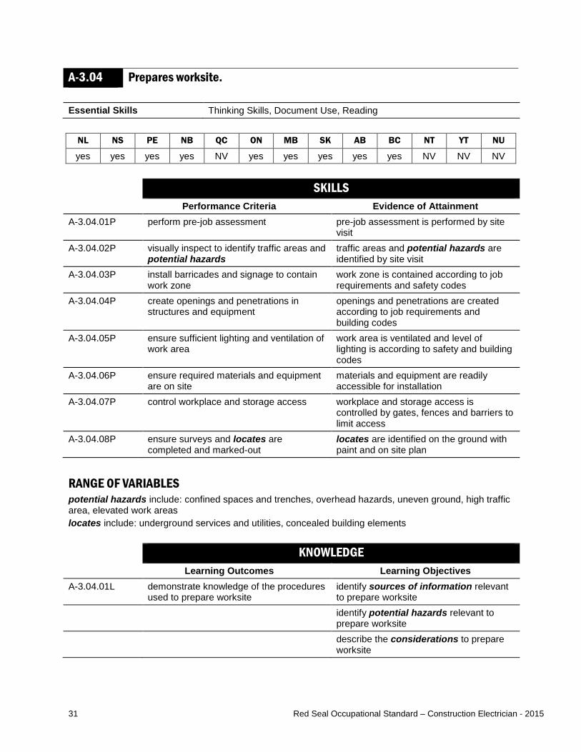
A-3.04 Prepares worksite. Essential Skills Thinking Skills, Document Use, Reading
NL NS PE NB QC ON MB SK AB BC NT YT NU
yes yes yes yes NV yes yes yes yes yes NV NV NV SKILLS
Performance Criteria Evidence of Attainment A-3.04.01P perform pre-job assessment pre-job assessment is performed by site
visit A-3.04.02P visually inspect to identify traffic areas and
potential hazards traffic areas and potential hazards are identified by site visit
A-3.04.03P install barricades and signage to contain work zone
work zone is contained according to job requirements and safety codes
A-3.04.04P create openings and penetrations in structures and equipment
openings and penetrations are created according to job requirements and building codes
A-3.04.05P ensure sufficient lighting and ventilation of work area
work area is ventilated and level of lighting is according to safety and building codes
A-3.04.06P ensure required materials and equipment are on site
materials and equipment are readily accessible for installation
A-3.04.07P control workplace and storage access workplace and storage access is controlled by gates, fences and barriers to limit access
A-3.04.08P ensure surveys and locates are completed and marked-out
locates are identified on the ground with paint and on site plan
RANGE OF VARIABLES potential hazards include: confined spaces and trenches, overhead hazards, uneven ground, high traffic area, elevated work areas locates include: underground services and utilities, concealed building elements KNOWLEDGE
Learning Outcomes Learning Objectives A-3.04.01L demonstrate knowledge of the procedures
used to prepare worksite identify sources of information relevant to prepare worksite
identify potential hazards relevant to prepare worksite
describe the considerations to prepare worksite
32 Red Seal Occupational Standard – Construction Electrician - 2015
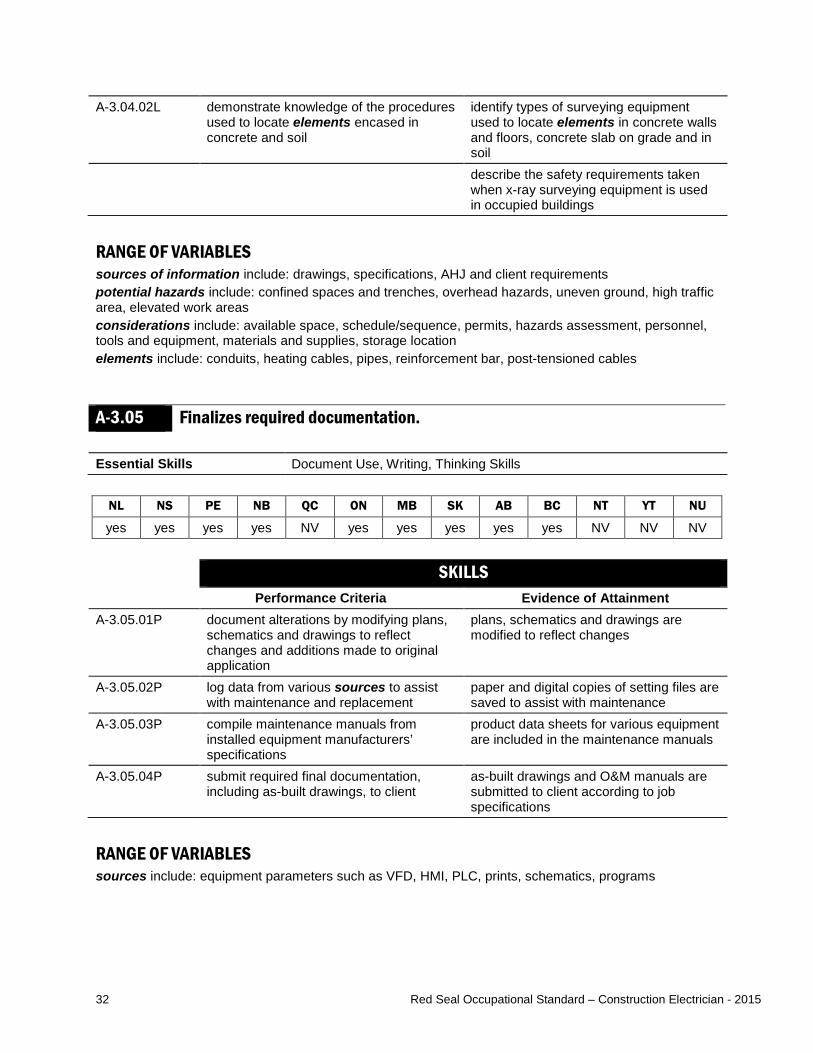
A-3.04.02L demonstrate knowledge of the procedures used to locate elements encased in concrete and soil
identify types of surveying equipment used to locate elements in concrete walls and floors, concrete slab on grade and in soil
describe the safety requirements taken when x-ray surveying equipment is used in occupied buildings
RANGE OF VARIABLES sources of information include: drawings, specifications, AHJ and client requirements potential hazards include: confined spaces and trenches, overhead hazards, uneven ground, high traffic area, elevated work areas considerations include: available space, schedule/sequence, permits, hazards assessment, personnel, tools and equipment, materials and supplies, storage location elements include: conduits, heating cables, pipes, reinforcement bar, post-tensioned cables
A-3.05 Finalizes required documentation. Essential Skills Document Use, Writing, Thinking Skills
NL NS PE NB QC ON MB SK AB BC NT YT NU
yes yes yes yes NV yes yes yes yes yes NV NV NV SKILLS
Performance Criteria Evidence of Attainment A-3.05.01P document alterations by modifying plans,
schematics and drawings to reflect changes and additions made to original application
plans, schematics and drawings are modified to reflect changes
A-3.05.02P log data from various sources to assist with maintenance and replacement
paper and digital copies of setting files are saved to assist with maintenance
A-3.05.03P compile maintenance manuals from installed equipment manufacturers’ specifications
product data sheets for various equipment are included in the maintenance manuals
A-3.05.04P submit required final documentation, including as-built drawings, to client
as-built drawings and O&M manuals are submitted to client according to job specifications
RANGE OF VARIABLES sources include: equipment parameters such as VFD, HMI, PLC, prints, schematics, programs

33 Red Seal Occupational Standard – Construction Electrician - 2015
KNOWLEDGE Learning Outcomes Learning Objectives
A-3.05.01L demonstrate knowledge of documentation, its purpose, application and use
describe and identify types of documentation developed from different tasks
describe procedures for finalizing documentation
Task A-4 Fabricates and installs support components. TASK DESCRIPTOR Construction electricians fabricate support structures to protect and support equipment and components. They use various methods to secure equipment to structures in order to maintain a safe installation, and reduce hazards and unwanted movements. Seismic restraint systems are used as a secondary support. INDUSTRY EXPECTED PERFORMANCE The task must be performed according to the applicable jurisdictional codes and standards. All health and safety standards must be respected. Work should be done efficiently and at a high quality without material waste or harm to the environment. All requirements of the manufacturer, client specifications and the AHJ must be met. At a journeyperson level of performance, all tasks must be done with minimal direction and supervision.
A-4.01 Fabricates support structures. Essential Skills Numeracy, Document Use, Thinking Skills
NL NS PE NB QC ON MB SK AB BC NT YT NU
yes yes yes yes NV yes yes yes yes yes NV NV NV SKILLS
Performance Criteria Evidence of Attainment A-4.01.01P measure equipment to determine support
structure size, strength and weight dimensions of support structure is determined according to equipment size
A-4.01.02P draw sketch sketch is drawn with dimensions and measurements of support structure and equipment
A-4.01.03P determine material for support structure materials are selected according to job specifications and factors
A-4.01.04P select and use fasteners fasteners are selected to meet job specifications and site conditions

34 Red Seal Occupational Standard – Construction Electrician - 2015
A-4.01.05P prepare material by cutting to size and drilling holes
materials are cut and drilled to size according to sketch
A-4.01.06P assemble material to create structure structure is assembled according to sketch, and is straight and free of sharp protrusions
RANGE OF VARIABLES materials include: wood, steel, aluminum factors include: environment, strength and durability ratings, cost service fasteners include: anchors, nuts, bolts, screws fasteners include: screws, straps, inserts, anchors, wedge clamps, seismic restraints, insulators KNOWLEDGE
Learning Outcomes Learning Objectives A-4.01.01L demonstrate knowledge of interpreting,
creating and extracting information from sketches, drawings and specifications
create, interpret and extract information from sketches, drawings and specifications
identify support materials, their characteristics and application
identify fasteners, their characteristics and application according to job specifications and site conditions
A-4.01.02L demonstrate knowledge of procedures for fabricating support structures
describe procedures used to fabricate support structures
RANGE OF VARIABLES materials include: wood, steel, aluminum fasteners include: anchors, nuts, bolts, screws
35 Red Seal Occupational Standard – Construction Electrician - 2015
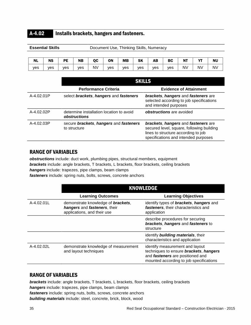
A-4.02 Installs brackets, hangers and fasteners. Essential Skills Document Use, Thinking Skills, Numeracy
NL NS PE NB QC ON MB SK AB BC NT YT NU
yes yes yes yes NV yes yes yes yes yes NV NV NV SKILLS
Performance Criteria Evidence of Attainment A-4.02.01P select brackets, hangers and fasteners brackets, hangers and fasteners are
selected according to job specifications and intended purposes
A-4.02.02P determine installation location to avoid obstructions
obstructions are avoided
A-4.02.03P secure brackets, hangers and fasteners to structure
brackets, hangers and fasteners are secured level, square, following building lines to structure according to job specifications and intended purposes
RANGE OF VARIABLES obstructions include: duct work, plumbing pipes, structural members, equipment brackets include: angle brackets, T brackets, L brackets, floor brackets, ceiling brackets hangers include: trapezes, pipe clamps, beam clamps fasteners include: spring nuts, bolts, screws, concrete anchors KNOWLEDGE
Learning Outcomes Learning Objectives A-4.02.01L demonstrate knowledge of brackets,
hangers and fasteners, their applications, and their use
identify types of brackets, hangers and fasteners, their characteristics and application
describe procedures for securing brackets, hangers and fasteners to structure
identify building materials, their characteristics and application
A-4.02.02L demonstrate knowledge of measurement and layout techniques
identify measurement and layout techniques to ensure brackets, hangers and fasteners are positioned and mounted according to job specifications
RANGE OF VARIABLES brackets include: angle brackets, T brackets, L brackets, floor brackets, ceiling brackets hangers include: trapezes, pipe clamps, beam clamps fasteners include: spring nuts, bolts, screws, concrete anchors building materials include: steel, concrete, brick, block, wood

36 Red Seal Occupational Standard – Construction Electrician - 2015
A-4.03 Installs seismic restraint systems. Essential Skills Document Use, Reading, Thinking Skills
NL NS PE NB QC ON MB SK AB BC NT YT NU
no yes yes yes NV yes no yes yes yes NV NV NV SKILLS
Performance Criteria Evidence of Attainment A-4.03.01P select and fabricate seismic restraint
systems seismic restraint systems are selected and fabricated according to job specifications and jurisdictional regulations
A-4.03.02P determine installation location to avoid obstructions
obstructions are avoided
A-4.03.03P position, mount and secure seismic restraint systems to structure
seismic restraint systems are positioned, mounted and secured according to structure location, job specifications and jurisdictional regulations
RANGE OF VARIABLES seismic restraint systems include: chains, cables, rods, aircraft wires obstructions include: duct work, plumbing pipes KNOWLEDGE
Learning Outcomes Learning Objectives A-4.03.01L demonstrate knowledge of seismic
restraint systems, their applications and their use
identify types of seismic restraint systems, their characteristics and requirements
describe procedures for mounting and securing seismic restraint systems to structure
identify materials to be installed
RANGE OF VARIABLES seismic restraint systems include: chains, cables, rods, aircraft wires

37 Red Seal Occupational Standard – Construction Electrician - 2015
Task A-5 Commissions and decommissions electrical systems. TASK DESCRIPTOR Construction electricians start up and commission electrical systems to ensure safe and intended operation. Commissioning of electrical systems may require liaison with equipment manufacturers. Construction electricians also shut down systems to perform preventative maintenance or to replace defective equipment. They decommission systems to prepare them for removal. INDUSTRY EXPECTED PERFORMANCE The task must be performed according to the applicable jurisdictional codes and standards. All health and safety standards must be respected. Work should be done efficiently and at a high quality without material waste or harm to the environment. All requirements of the manufacturer, client specifications and the AHJ must be met. At a journeyperson level of performance, all tasks must be done with minimal direction and supervision.
A-5.01 Performs startup and shutdown procedures. Essential Skills Document Use, Thinking Skills, Oral Communication
NL NS PE NB QC ON MB SK AB BC NT YT NU
yes yes yes yes NV yes yes yes yes yes NV NV NV SKILLS
Performance Criteria Evidence of Attainment A-5.01.01P identify equipment that needs to be
energized equipment is identified and its source of supply is verified by documentation
A-5.01.02P identify equipment that needs to be de-energized
equipment is identified and its source of supply is locked out and tagged out
A-5.01.03P test cables and conductors for ground faults and phase identification
cables and conductors are tested with an insulation resistance tester and continuity tester
A-5.01.04P follow specifications sequence for startup system is energized according to job specifications, type of system and manufacturers’ specifications
A-5.01.05P follow specifications sequence for shutdown
system is de-energized according to job specifications, type of system and manufacturers’ specifications
A-5.01.06P check system peripherals for specified operation
system peripherals operate according to job and manufacturers’ specifications
A-5.01.07P apply temporary safety ground on shutdown, and remove on startup
temporary safety grounds are used and removed according to safety codes, CEC and job requirements
A-5.01.08P verify busbar connections and torquing of bolts
busbars are torqued according to manufacturers’ specifications

38 Red Seal Occupational Standard – Construction Electrician - 2015
A-5.01.09P verify that safety and shipping material has been removed from equipment and check for tools and loose hardware prior to startup
shipping material, construction debris and tools are removed from equipment and loose equipment hardware is secured prior to startup
A-5.01.10P notify required personnel of startup and shutdown procedures
personnel is cleared from area prior to startup and shutdown procedures
RANGE OF VARIABLES system peripherals include: detection, status and alarm systems KNOWLEDGE
Learning Outcomes Learning Objectives A-5.01.01L demonstrate knowledge of startup and
shutdown procedures and their purpose identify hazards and describe safe work practices pertaining to starting up and shutting down systems or equipment
identify the purpose of starting up and shutting down and the types of systems and equipment requiring it
identify and interpret information sources and documentation pertaining to the starting up and shutting down of systems or equipment
RANGE OF VARIABLES hazards include: arc flash/blast, moving and rotating equipment, electric shocks information sources include: O&M manuals, single line diagrams, schematics, panel schedules, CEC Z460, Z462 and Z463
A-5.02 Performs commissioning and decommissioning of systems. Essential Skills Document Use, Numeracy, Working with Others
NL NS PE NB QC ON MB SK AB BC NT YT NU
yes yes yes yes NV yes yes yes yes yes NV NV NV SKILLS
Performance Criteria Evidence of Attainment A-5.02.01P check documentation and nameplate data
for operational parameters operational parameters are set or adjusted according to manufacturers’ and job specifications
A-5.02.02P confirm system peripherals are functional
system peripherals are operating to their intended purpose
A-5.02.03P perform operational checks results of operational checks are recorded and documented
39 Red Seal Occupational Standard – Construction Electrician - 2015
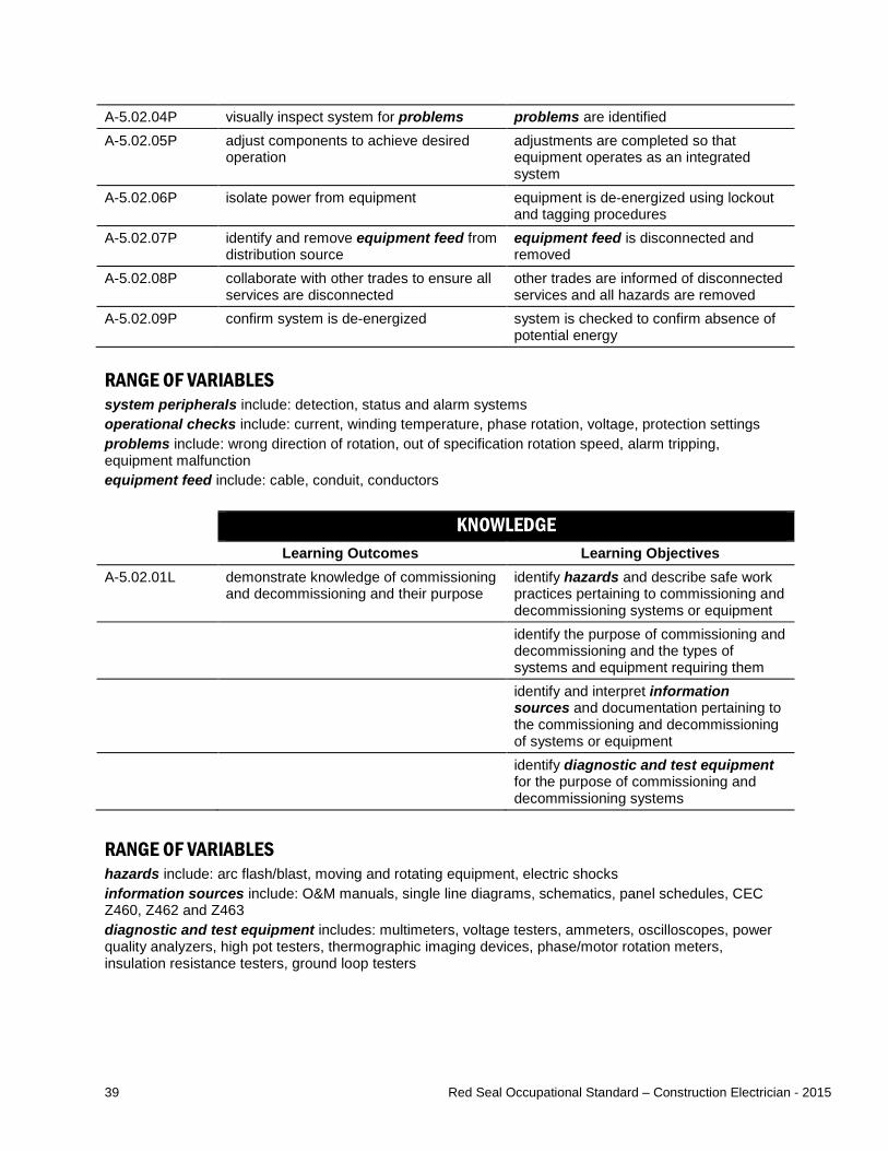
A-5.02.04P visually inspect system for problems problems are identified A-5.02.05P adjust components to achieve desired
operation adjustments are completed so that equipment operates as an integrated system
A-5.02.06P isolate power from equipment equipment is de-energized using lockout and tagging procedures
A-5.02.07P identify and remove equipment feed from distribution source
equipment feed is disconnected and removed
A-5.02.08P collaborate with other trades to ensure all services are disconnected
other trades are informed of disconnected services and all hazards are removed
A-5.02.09P confirm system is de-energized system is checked to confirm absence of potential energy
RANGE OF VARIABLES system peripherals include: detection, status and alarm systems operational checks include: current, winding temperature, phase rotation, voltage, protection settings problems include: wrong direction of rotation, out of specification rotation speed, alarm tripping, equipment malfunction equipment feed include: cable, conduit, conductors KNOWLEDGE
Learning Outcomes Learning Objectives A-5.02.01L demonstrate knowledge of commissioning
and decommissioning and their purpose identify hazards and describe safe work practices pertaining to commissioning and decommissioning systems or equipment
identify the purpose of commissioning and decommissioning and the types of systems and equipment requiring them
identify and interpret information sources and documentation pertaining to the commissioning and decommissioning of systems or equipment
identify diagnostic and test equipment for the purpose of commissioning and decommissioning systems
RANGE OF VARIABLES hazards include: arc flash/blast, moving and rotating equipment, electric shocks information sources include: O&M manuals, single line diagrams, schematics, panel schedules, CEC Z460, Z462 and Z463 diagnostic and test equipment includes: multimeters, voltage testers, ammeters, oscilloscopes, power quality analyzers, high pot testers, thermographic imaging devices, phase/motor rotation meters, insulation resistance testers, ground loop testers

40 Red Seal Occupational Standard – Construction Electrician - 2015
Task A-6 Uses communication and mentoring techniques. TASK DESCRIPTOR Learning in the trades is done primarily in the workplace with tradespeople passing on their skills and knowledge to apprentices, as well as sharing knowledge among themselves. Apprenticeship is, and always has been about mentoring – learning workplace skills and passing them on. Because of the importance of this to the trade, this task covers the activities related to communication in the workplace and mentoring skills. INDUSTRY EXPECTED PERFORMANCE Communication and mentoring on the job must be done with mutual respect and must take into account personal responsibilities, attitude, oral communication and career outcomes. Construction electricians must communicate with appropriate trade terminology as defined in occupational health and safety requirements and the trades’ codes, such as the Canadian Electrical Code (CEC) and the National Building Code (NBC). All communication must be done in accordance with the Canadian Human Rights Act and be free from harassment and discrimination. Mentoring styles can vary by workplace and individual. Different things work for different people. A focus on workplace mentoring is about helping ensure that the skills, tips, techniques and best practices are passed on. This benefits industry as a whole by raising productivity and creating safer and healthier workplaces.
A-6.01 Uses communication techniques. Essential Skills Oral Communication, Working with Others, Continuous Learning, Digital
Technology
NL NS PE NB QC ON MB SK AB BC NT YT NU
yes yes yes yes NV yes yes yes yes yes NV NV NV SKILLS
Performance Criteria Evidence of Attainment A-6.01.01P demonstrates two-way communication
practices instructions and messages are understood by both parties involved in communication
A-6.01.02P listens using active listening practices steps of active listening are utilized A-6.01.03P receives and responds to feedback on
work response to feedback indicates understanding and corrective measures are taken
A-6.01.04P uses questioning to improve communication
questions enhance understanding, on-the-job training and goal setting
A-6.01.05P participates in safety and information meetings
meetings are attended and information is understood and applied

41 Red Seal Occupational Standard – Construction Electrician - 2015
RANGE OF VARIABLES active listening includes: hearing, interpreting, reflecting, responding, paraphrasing KNOWLEDGE
Learning Outcomes Learning Objectives A-6.01.01L demonstrate knowledge of trade
terminology define terminology used in the trade
A-6.01.02L demonstrate knowledge of effective communication practices
describe the importance of using effective verbal and non-verbal communication with people in the workplace
identify sources of information to effectively communicate
identify communication and learning styles
identify personal responsibilities and attitudes that contribute to on-the-job success
identify communication that constitutes harassment and discrimination
RANGE OF VARIABLES people in the workplace include: other tradespeople, colleagues, apprentices, supervisors, clients, AHJ, manufacturers sources of information include: regulations, codes, occupational health and safety requirements, AHJ requirements, prints, drawings, specifications, company and client documentation learning styles include: seeing it, hearing it, trying it personal responsibilities and attitudes include, but are not limited to: asking questions, working safely, accepting constructive feedback, time management and punctuality, respect for authority, good stewardship of materials, tools and property, efficient work practice harassment includes objectionable conduct, comment or display made either on a one-time or continuous basis that demeans, belittles, or causes personal humiliation or embarrassment to the recipient discrimination is prohibited based on race, national or ethnic origin, colour, religion, age, sex, sexual orientation, marital status, family status, disability or conviction for which a pardon has been granted

42 Red Seal Occupational Standard – Construction Electrician - 2015
A-6.02 Uses mentoring techniques. Essential Skills Oral Communication, Working with Others, Continuous Learning
NL NS PE NB QC ON MB SK AB BC NT YT NU
yes yes yes yes NV yes yes yes yes yes NV NV NV SKILLS
Performance Criteria Evidence of Attainment A-6.02.01P identify and communicate learning
objective and point of lesson apprentice or learner can explain the objective and point of the lesson
A-6.02.02P link lesson to other lessons and the job lesson order and unplanned learning opportunities are defined
A-6.02.03P demonstrates performance of a skill to an apprentice or learner
steps required to demonstrate a skill are performed
A-6.02.04P set up conditions required for an apprentice or learner to practice a skill
practice conditions are set up so that the skill can be practiced safely by the apprentice or learner
A-6.02.05P assess apprentice or learner’s ability to perform tasks with increasing independence
performance of apprentice or learner improves with practice to a point where skill can be done with little supervision
A-6.02.06P give supportive and corrective feedback apprentice or learner adopts best practice after having been given supportive or corrective feedback
A-6.02.07P support apprentices in pursuing technical training opportunities
technical training is completed within timeframe prescribed by apprenticeship authority
A-6.02.08P support equity group learners and apprentices
workplace is harassment and discrimination-free
A-6.02.09P implement probationary period for learners to assess their suitability to the trade
commitment is demonstrated by the learner and more suitable career options are provided to others
RANGE OF VARIABLES steps required to demonstrate a skill include: 5 Ws, explaining, showing, giving encouragement, following up to ensure skill is performed correctly practice conditions means: guided, limited independence, full independence

43 Red Seal Occupational Standard – Construction Electrician - 2015
KNOWLEDGE Learning Outcomes Learning Objectives
A-6.02.01L identify, explain and demonstrate strategies for learning skills in the workplace
describe the importance of individual experience
describe the shared responsibilities for workplace learning
determine one’s own learning preferences and explain how these relate to learning new skills
describe the importance of different types of skills in the workplace
describe the importance of essential skills in the workplace
identify different ways of learning identify different learning needs and
strategies to meet learning needs identify strategies to assist in learning a
skill A-6.02.02L identify, explain and demonstrate
strategies for teaching workplace skills identify different roles played by a workplace mentor
describe the steps involved in teaching skills
explain the importance of identifying the point of a lesson
identify how to choose a good time to present a lesson
explain the importance of linking the lessons
identify the components of the skill (the context)
describe considerations in setting up opportunities for skill practice
explain the importance of providing feedback
identify techniques for giving effective feedback
describe a skills assessment identify methods of assessing progress explain how to adjust a lesson to different
situations

44 Red Seal Occupational Standard – Construction Electrician - 2015
RANGE OF VARIABLES essential skills are: reading, writing, document use, oral communication, numeracy, thinking skills, working with others, digital technology, continuous learning learning needs include: learning disabilities, learning preferences, language proficiency strategies to assist in learning a skill include: understanding the basic principles of instruction, developing coaching skills, being mature and patient, providing feedback steps for teaching skills include: identifying the point of the lesson, linking the lesson, demonstrating the skill, providing practice, giving feedback, assessing skills and progress

45 Red Seal Occupational Standard – Construction Electrician - 2015
MAJOR WORK ACTIVITY B INSTALLS, SERVICES AND MAINTAINS GENERATING, DISTRIBUTION AND SERVICE SYSTEMS Task B-7 Installs, services and maintains consumer/supply services and metering equipment. TASK DESCRIPTOR Service entrance equipment provides power for single-phase and three-phase electrical systems and equipment. Consumer services can provide normal, emergency and temporary power. This equipment allows for the safe utilization of electricity. For the purpose of this standard, installation includes both new installations and upgrading of systems by removing and replacing components. Construction electricians service single- and three-phase consumer/supply services and metering equipment by troubleshooting, diagnosing faults, and repairing them. They also perform maintenance to ensure the consumer/supply services and metering equipment are in good operating condition. INDUSTRY EXPECTED PERFORMANCE The task must be performed according to the applicable jurisdictional codes and standards. All health and safety standards must be respected. Work should be done efficiently and at a high quality without material waste or harm to the environment. All requirements of the manufacturer, client specifications and the AHJ must be met. At a journeyperson level of performance, all tasks must be done with minimal direction and supervision.
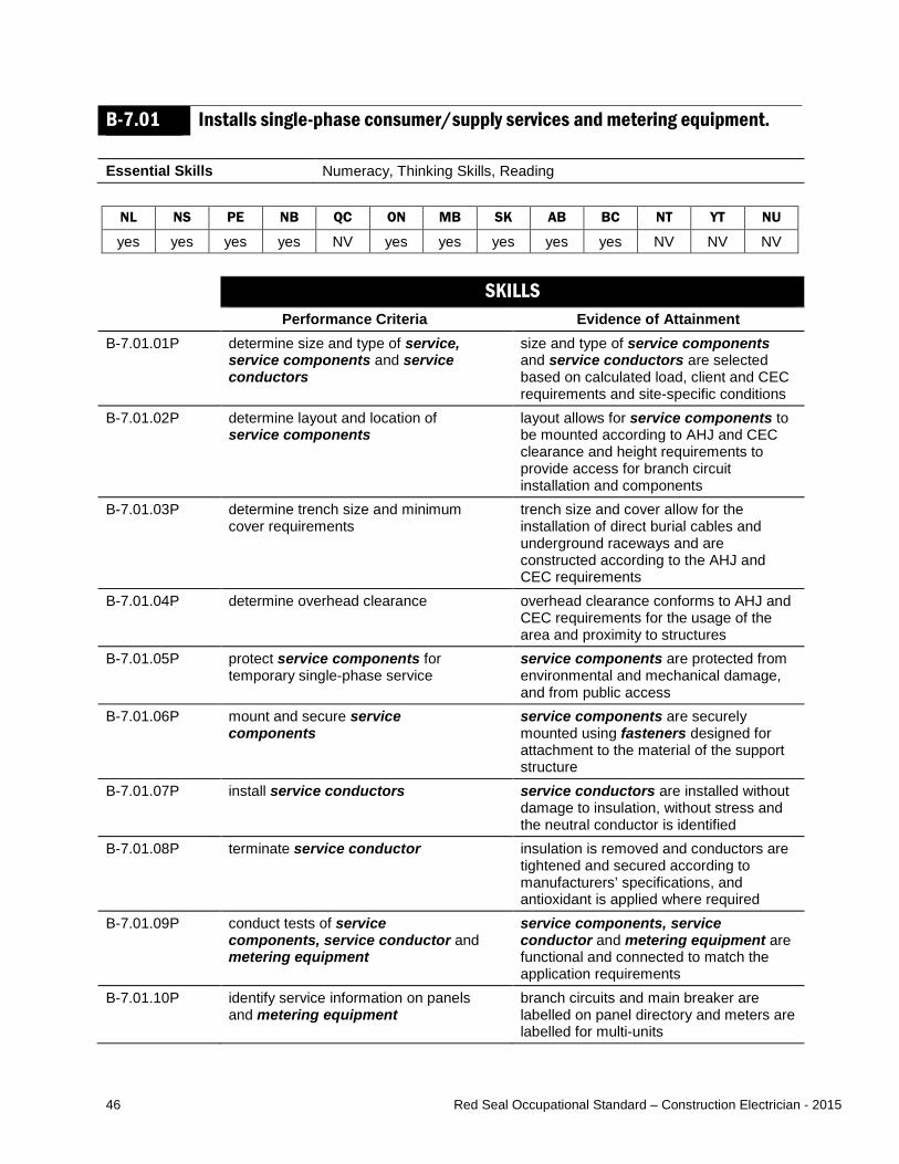
46 Red Seal Occupational Standard – Construction Electrician - 2015
B-7.01 Installs single-phase consumer/supply services and metering equipment. Essential Skills Numeracy, Thinking Skills, Reading
NL NS PE NB QC ON MB SK AB BC NT YT NU
yes yes yes yes NV yes yes yes yes yes NV NV NV SKILLS
Performance Criteria Evidence of Attainment B-7.01.01P determine size and type of service,
service components and service conductors
size and type of service components and service conductors are selected based on calculated load, client and CEC requirements and site-specific conditions
B-7.01.02P determine layout and location of service components
layout allows for service components to be mounted according to AHJ and CEC clearance and height requirements to provide access for branch circuit installation and components
B-7.01.03P determine trench size and minimum cover requirements
trench size and cover allow for the installation of direct burial cables and underground raceways and are constructed according to the AHJ and CEC requirements
B-7.01.04P determine overhead clearance overhead clearance conforms to AHJ and CEC requirements for the usage of the area and proximity to structures
B-7.01.05P protect service components for temporary single-phase service
service components are protected from environmental and mechanical damage, and from public access
B-7.01.06P mount and secure service components
service components are securely mounted using fasteners designed for attachment to the material of the support structure
B-7.01.07P install service conductors service conductors are installed without damage to insulation, without stress and the neutral conductor is identified
B-7.01.08P terminate service conductor insulation is removed and conductors are tightened and secured according to manufacturers’ specifications, and antioxidant is applied where required
B-7.01.09P conduct tests of service components, service conductor and metering equipment
service components, service conductor and metering equipment are functional and connected to match the application requirements
B-7.01.10P identify service information on panels and metering equipment
branch circuits and main breaker are labelled on panel directory and meters are labelled for multi-units
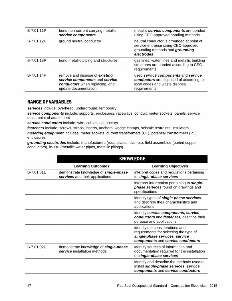
47 Red Seal Occupational Standard – Construction Electrician - 2015
B-7.01.11P bond non-current carrying metallic service components
metallic service components are bonded using CEC-approved bonding methods
B-7.01.12P ground neutral conductor neutral conductor is grounded at point of service entrance using CEC-approved grounding methods and grounding electrodes
B-7.01.13P bond metallic piping and structures gas lines, water lines and metallic building structures are bonded according to CEC requirements
B-7.01.14P remove and dispose of existing service components and service conductors when replacing, and update documentation
used service components and service conductors are disposed of according to local codes and waste disposal requirements
RANGE OF VARIABLES services include: overhead, underground, temporary service components include: supports, enclosures, raceways, conduit, meter sockets, panels, service mast, point of attachment service conductors include: wire, cables, conductors fasteners include: screws, straps, inserts, anchors, wedge clamps, seismic restraints, insulators metering equipment includes: meter sockets, current transformers (CT), potential transformers (PT), enclosures grounding electrodes include: manufacturers (rods, plates, clamps), field assembled (buried copper conductors), in-situ (metallic water pipes, metallic pilings). KNOWLEDGE
Learning Outcomes Learning Objectives B-7.01.01L demonstrate knowledge of single-phase
services and their applications interpret codes and regulations pertaining to single-phase services
interpret information pertaining to single-phase services found on drawings and specifications
identify types of single-phase services and describe their characteristics and applications
identify service components, service conductors and fasteners, describe their purpose and applications
identify the considerations and requirements for selecting the type of single-phase services, service components and service conductors
B-7.01.02L demonstrate knowledge of single-phase service installation methods
identify sources of information and documentation required for the installation of single-phase services
identify and describe the methods used to install single-phase services, service components and service conductors

48 Red Seal Occupational Standard – Construction Electrician - 2015
identify and describe the methods used to connect service conductors
identify the methods of grounding and bonding single-phase services
B-7.01.03L demonstrate knowledge of load calculations for a single-phase service
identify the method used to calculate load
calculate load for a single-phase service
RANGE OF VARIABLES single-phase services include: temporary service, overhead, underground, single and multiple metering service conductors include: wire, cables, conductors service components include: supports, enclosures, raceways, conduit, meter sockets, panels, service mast, point of attachment fasteners include: screws, straps, inserts, anchors, wedge clamps, seismic restraints, insulators
B-7.02 Installs three-phase consumer/supply services and metering equipment. Essential Skills Numeracy, Thinking Skills, Reading
NL NS PE NB QC ON MB SK AB BC NT YT NU
yes yes yes yes NV yes yes yes yes yes NV NV NV SKILLS
Performance Criteria Evidence of Attainment B-7.02.01P determine size and type of service,
service components and service conductors
size and type of service components and service conductors are selected according to calculated load, client and CEC requirements and site-specific conditions
B-7.02.02P determine layout and location of service components
layout allows for service components to be mounted according to the AHJ and CEC clearance and height requirements to provide access for branch circuit installation
B-7.02.03P determine trench size and minimum cover requirements
trench size and cover allows for the installation of direct burial cables and underground raceways, and are constructed according to the AHJ and CEC requirements
B-7.02.04P determine overhead clearance overhead clearance conforms to the AHJ and the CEC requirements for the usage of the area and proximity to structures
B-7.02.05P protect service components for temporary three-phase service
service components are protected from environmental and mechanical damage, and from public access
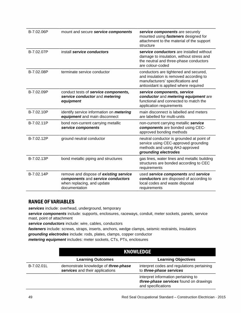
49 Red Seal Occupational Standard – Construction Electrician - 2015
B-7.02.06P mount and secure service components service components are securely mounted using fasteners designed for attachment to the material of the support structure
B-7.02.07P install service conductors service conductors are installed without damage to insulation, without stress and the neutral and three-phase conductors are colour-coded
B-7.02.08P terminate service conductor conductors are tightened and secured, and insulation is removed according to manufacturers’ specifications and antioxidant is applied where required
B-7.02.09P conduct tests of service components, service conductor and metering equipment
service components, service conductor and metering equipment are functional and connected to match the application requirements
B-7.02.10P identify service information on metering equipment and main disconnect
main disconnect is labelled and meters are labelled for multi-units
B-7.02.11P bond non-current carrying metallic service components
non-current carrying metallic service components are bonded using CEC-approved bonding methods
B-7.02.12P ground neutral conductor neutral conductor is grounded at point of service using CEC-approved grounding methods and using AHJ-approved grounding electrodes
B-7.02.13P bond metallic piping and structures gas lines, water lines and metallic building structures are bonded according to CEC requirements
B-7.02.14P remove and dispose of existing service components and service conductors when replacing, and update documentation
used service components and service conductors are disposed of according to local codes and waste disposal requirements
RANGE OF VARIABLES services include: overhead, underground, temporary service components include: supports, enclosures, raceways, conduit, meter sockets, panels, service mast, point of attachment service conductors include: wire, cables, conductors fasteners include: screws, straps, inserts, anchors, wedge clamps, seismic restraints, insulators grounding electrodes include: rods, plates, clamps, copper conductor metering equipment includes: meter sockets, CTs, PTs, enclosures KNOWLEDGE
Learning Outcomes Learning Objectives B-7.02.01L demonstrate knowledge of three-phase
services and their applications interpret codes and regulations pertaining to three-phase services
interpret information pertaining to three-phase services found on drawings and specifications
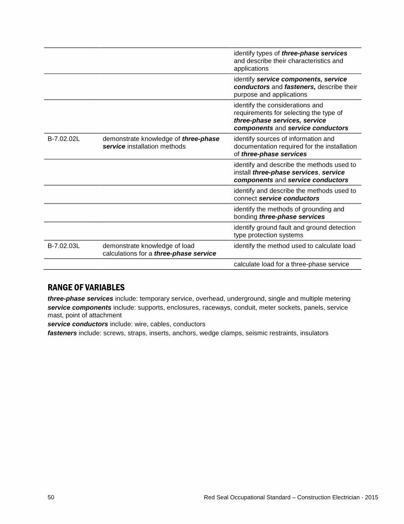
50 Red Seal Occupational Standard – Construction Electrician - 2015
identify types of three-phase services and describe their characteristics and applications
identify service components, service conductors and fasteners, describe their purpose and applications
identify the considerations and requirements for selecting the type of three-phase services, service components and service conductors
B-7.02.02L demonstrate knowledge of three-phase service installation methods
identify sources of information and documentation required for the installation of three-phase services
identify and describe the methods used to install three-phase services, service components and service conductors
identify and describe the methods used to connect service conductors
identify the methods of grounding and bonding three-phase services
identify ground fault and ground detection type protection systems
B-7.02.03L demonstrate knowledge of load calculations for a three-phase service
identify the method used to calculate load
calculate load for a three-phase service
RANGE OF VARIABLES three-phase services include: temporary service, overhead, underground, single and multiple metering service components include: supports, enclosures, raceways, conduit, meter sockets, panels, service mast, point of attachment service conductors include: wire, cables, conductors fasteners include: screws, straps, inserts, anchors, wedge clamps, seismic restraints, insulators

51 Red Seal Occupational Standard – Construction Electrician - 2015
B-7.03 Performs servicing and maintenance of single-phase services and metering equipment.
Essential Skills Oral Communication, Digital Technology, Writing
NL NS PE NB QC ON MB SK AB BC NT YT NU
yes yes yes yes NV yes yes yes yes yes NV NV NV SKILLS
Performance Criteria Evidence of Attainment B-7.03.01P obtain detailed description of malfunction
from client malfunction issues and information are identified and recorded
B-7.03.02P conduct field assessment using diagnostic and test equipment
field assessments are conducted using the diagnostic and test equipment that provides the most definitive diagnostics
B-7.03.03P determine source of malfunction based on field assessment
source of malfunction is identified
B-7.03.04P determine course of action course of action for the type of malfunction is identified
B-7.03.05P repair malfunctioning components repaired components are operational B-7.03.06P select replacement components equivalent replacement components
(original equipment manufacturer [OEM] replacement when mandated) are selected
B-7.03.07P install replacement components replacement components are installed with minimal disruptions
B-7.03.08P determine maintenance requirements maintenance requirements are identified by consequence of failure
B-7.03.09P create maintenance schedule maintenance schedule is created by considering maintenance requirements
B-7.03.10P follow maintenance schedule maintenance tasks are done according to established schedule
B-7.03.11P conduct tests using diagnostic and test equipment
tests are conducted according to established maintenance schedule and test results are recorded
B-7.03.12P update maintenance log maintenance log is updated to reflect servicing and maintenance tasks performed
RANGE OF VARIABLES field assessments include: sensory inspections, technical inspections diagnostic and test equipment includes: multimeters, voltage testers, ammeters, power quality analyzers, thermographic imaging devices, insulation resistance testers

52 Red Seal Occupational Standard – Construction Electrician - 2015
KNOWLEDGE Learning Outcomes Learning Objectives
B-7.03.01L demonstrate knowledge of the methods used to service and maintain single-phase service
describe the methods used to service single-phase services and their components
describe the methods used to maintain single-phase services and their components
B-7.03.01L demonstrate knowledge of the theory of single-phase systems
describe theory of Edison three-wire system
describe single-phase circuit fundamentals
B-7.04 Performs servicing and maintenance of three-phase services and metering equipment.
Essential Skills Oral Communication, Digital Technology, Writing
NL NS PE NB QC ON MB SK AB BC NT YT NU
yes yes yes yes NV yes yes yes yes yes NV NV NV SKILLS
Performance Criteria Evidence of Attainment B-7.04.01P obtain detailed description of malfunction
from client malfunction issues and information are identified and recorded
B-7.04.02P conduct field assessment using diagnostic and test equipment
field assessments are conducted using the diagnostic and test equipment that provides the most definitive diagnostics
B-7.04.03P determine source of malfunction based on field assessment
source of malfunction is identified
B-7.04.04P determine course of action course of action for the type of malfunction is identified
B-7.04.05P repair malfunctioning components repaired components are operational B-7.04.06P select replacement components equivalent replacement components
(OEM replacement when mandated) are selected
B-7.04.07P install replacement components replacement components are installed with minimal disruptions
B-7.04.08P determine maintenance requirements maintenance requirements are identified by consequence of failure
B-7.04.09P create maintenance schedule maintenance schedule is created by considering maintenance requirements

53 Red Seal Occupational Standard – Construction Electrician - 2015
B-7.04.10P follow maintenance schedule maintenance tasks are done according to established schedule
B-7.04.11P conduct tests using diagnostic and test equipment
tests are conducted according to established maintenance schedule and test results are recorded
B-7.04.12P update maintenance log maintenance log is updated to reflect servicing and maintenance tasks performed
RANGE OF VARIABLES field assessments include: sensory inspections, technical inspections diagnostic and test equipment includes: multimeters, voltage testers, ammeters, power quality analyzers, thermographic imaging devices, phase rotation meters, insulation resistance testers KNOWLEDGE
Learning Outcomes Learning Objectives B-7.04.01L demonstrate knowledge of the methods
used to service and maintain three-phase service
describe the methods to service three-phase services and their components
describe the methods used to maintain three-phase services and their components
B-7.04.02L demonstrate knowledge of the theory of three-phase systems
describe three-phase circuit fundamentals

54 Red Seal Occupational Standard – Construction Electrician - 2015
Task B-8 Installs, services and maintains protection devices. TASK DESCRIPTOR Overcurrent protection devices provide protection against overcurrent and short circuits to service entrance, feeder and branch circuit conductors, and equipment. Ground fault protection devices provide protection against shock and current leakage and are usually used in conjunction with overcurrent devices. Arc fault protection devices provide protection from the effects of arc faults by de-energizing the circuit when an arc fault is detected. These devices also have overload protection for the circuit. Surge protection devices prevent transient voltages that originate outside from entering into the whole system. For the purpose of this standard, installation includes both new installations and upgrading of systems by removing and replacing components. Construction electricians service overcurrent, ground fault, arc fault and surge protection devices by troubleshooting, diagnosing faults, replacing devices and repairing them. They also perform maintenance on these devices to ensure they are in good operating condition. INDUSTRY EXPECTED PERFORMANCE The task must be performed according to the applicable jurisdictional codes and standards. All health and safety standards must be respected. Work should be done efficiently and at a high quality without material waste or harm to the environment. All requirements of the manufacturer, client specifications and the AHJ must be met. At a journeyperson level of performance, all tasks must be done with minimal direction and supervision.
B-8.01 Installs overcurrent protection devices. Essential Skills Document Use, Numeracy, Thinking Skills
NL NS PE NB QC ON MB SK AB BC NT YT NU
yes yes yes yes NV yes yes yes yes yes NV NV NV SKILLS
Performance Criteria Evidence of Attainment B-8.01.01P determine type and size of enclosures enclosure type and size is based on load
requirements, environment and type of equipment
B-8.01.02P determine type and rating of overcurrent device
type and rating of overcurrent device is determined
B-8.01.03P secure overcurrent devices devices are mounted and secured to enclosures and/or busbars using hardware designed for the equipment
B-8.01.04P terminate overcurrent devices overcurrent devices are connected to line and load according to manufacturers’ specifications
B-8.01.05P set trip settings and ensure protection is coordinated
trip settings are based on load requirements, coordination studies and CEC requirements

55 Red Seal Occupational Standard – Construction Electrician - 2015
B-8.01.06P update required documentation and labels
branch circuits and distribution circuits are labelled on directories and other required documentation
B-8.01.07P remove and dispose of existing enclosures, overcurrent devices and hardware when replacing, and update documentation
all used enclosures, overcurrent devices and hardware are disposed of according to local codes and waste disposal requirements
RANGE OF VARIABLES enclosures include: CSA / National Electrical Manufacturers’ Association (NEMA) classification, hazardous locations (as defined by the Markings of Section 18 of the CEC) overcurrent devices include: fuses, breakers, relay protection hardware includes: bolts, screws, brackets, stand-offs, cabling, transition pieces required documentation includes: as-builts, schematics, panel schedules, log sheets, drive drawings, shop drawings KNOWLEDGE
Learning Outcomes Learning Objectives B-8.01.01L demonstrate knowledge of overcurrent
devices, their applications and operation interpret codes and regulations pertaining to overcurrent devices
interpret information pertaining to overcurrent devices found on drawings and specifications
explain the purpose and operation of overcurrent devices
explain the effects of short-circuit current and describe the associated damage to the circuit
identify types of overcurrent devices and describe their characteristics and applications
identify the considerations and requirements for selecting overcurrent devices
explain the purpose of coordination studies
B-8.01.02L demonstrate knowledge of the procedures used to install overcurrent devices
describe the procedures used to install overcurrent devices
explain the value of updating required documentation
explain the procedures used to adjust trip settings

56 Red Seal Occupational Standard – Construction Electrician - 2015
RANGE OF VARIABLES overcurrent devices include: fuses, breakers, relay protection required documentation includes: as-builts, schematics, panel schedules, log sheets, drive drawings, shop drawings
B-8.02 Installs ground fault, arc fault and surge protection devices. Essential Skills Document Use, Thinking Skills, Numeracy
NL NS PE NB QC ON MB SK AB BC NT YT NU
yes yes yes yes NV yes yes yes yes yes NV NV NV SKILLS
Performance Criteria Evidence of Attainment B-8.02.01P determine branch circuit and distribution
circuits protection requirements branch circuit and distribution circuits protection is determined according to location, environment, application and CEC requirements
B-8.02.02P determine type of ground fault protection device to use
ground fault protection devices are determined according to load, location, use and CEC requirements
B-8.02.03P determine type of arc fault protection device to use
arc fault protection devices are determined according to location and CEC requirements
B-8.02.04P determine type of surge protection device to use
surge protection devices are determined according to client requirements
B-8.02.05P mount protection devices devices are mounted and secured using hardware designed for the equipment
B-8.02.06P terminate protection devices conductors are tightened and secured, and insulation is removed according to manufacturers’ specifications
B-8.02.07P update required documentation and labels
branch circuits and distribution circuits are labelled on directories and other required documentation
B-8.02.08P remove and dispose of existing protection devices when replacing and update documentation
all used ground fault protection devices, arc fault protection devices and surge protection devices are disposed of according to local codes and waste disposal requirements
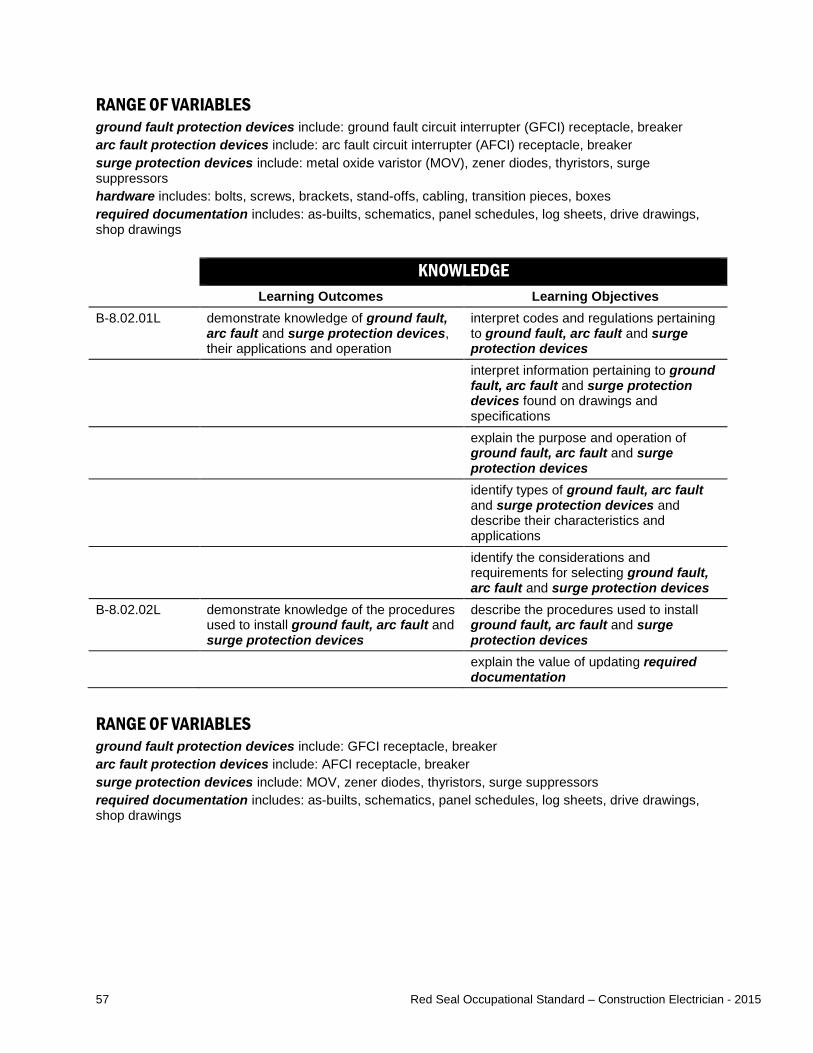
57 Red Seal Occupational Standard – Construction Electrician - 2015
RANGE OF VARIABLES ground fault protection devices include: ground fault circuit interrupter (GFCI) receptacle, breaker arc fault protection devices include: arc fault circuit interrupter (AFCI) receptacle, breaker surge protection devices include: metal oxide varistor (MOV), zener diodes, thyristors, surge suppressors hardware includes: bolts, screws, brackets, stand-offs, cabling, transition pieces, boxes required documentation includes: as-builts, schematics, panel schedules, log sheets, drive drawings, shop drawings KNOWLEDGE
Learning Outcomes Learning Objectives B-8.02.01L demonstrate knowledge of ground fault,
arc fault and surge protection devices, their applications and operation
interpret codes and regulations pertaining to ground fault, arc fault and surge protection devices
interpret information pertaining to ground fault, arc fault and surge protection devices found on drawings and specifications
explain the purpose and operation of ground fault, arc fault and surge protection devices
identify types of ground fault, arc fault and surge protection devices and describe their characteristics and applications
identify the considerations and requirements for selecting ground fault, arc fault and surge protection devices
B-8.02.02L demonstrate knowledge of the procedures used to install ground fault, arc fault and surge protection devices
describe the procedures used to install ground fault, arc fault and surge protection devices
explain the value of updating required documentation
RANGE OF VARIABLES ground fault protection devices include: GFCI receptacle, breaker arc fault protection devices include: AFCI receptacle, breaker surge protection devices include: MOV, zener diodes, thyristors, surge suppressors required documentation includes: as-builts, schematics, panel schedules, log sheets, drive drawings, shop drawings

58 Red Seal Occupational Standard – Construction Electrician - 2015
B-8.03 Performs servicing and maintenance of ground fault, arc fault and surge protection devices.
Essential Skills Oral Communication, Digital Technology, Writing
NL NS PE NB QC ON MB SK AB BC NT YT NU
yes yes yes yes NV yes yes yes yes yes NV NV NV SKILLS
Performance Criteria Evidence of Attainment B-8.03.01P obtain detailed description of malfunction
from client malfunction issues and information are identified and recorded
B-8.03.02P conduct field assessment using diagnostic and test equipment
field assessments are conducted using the diagnostic and test equipment that provides the most definitive diagnostics
B-8.03.03P determine source of malfunction based on field assessment
source of malfunction is identified
B-8.03.04P determine course of action course of action for the type of malfunction is identified
B-8.03.05P select replacement components equivalent replacement components (OEM replacement when mandated) are selected
B-8.03.06P install replacement components replacement components are installed with minimal disruptions
B-8.03.07P determine maintenance requirements maintenance requirements are identified by consequence of failure
B-8.03.08P create maintenance schedule maintenance schedule is created by considering maintenance requirements
B-8.03.09P follow maintenance schedule maintenance tasks are done according to established schedule
B-8.03.10P conduct tests using diagnostic and test equipment
tests are conducted according to established maintenance schedule, and test results are recorded
B-8.03.11P update maintenance log maintenance log is updated to reflect servicing and maintenance tasks performed
RANGE OF VARIABLES field assessments include: sensory inspections, technical inspections diagnostic and test equipment includes: multimeters, voltage testers, ammeters, power quality analyzers, thermographic imaging devices, insulation resistance testers
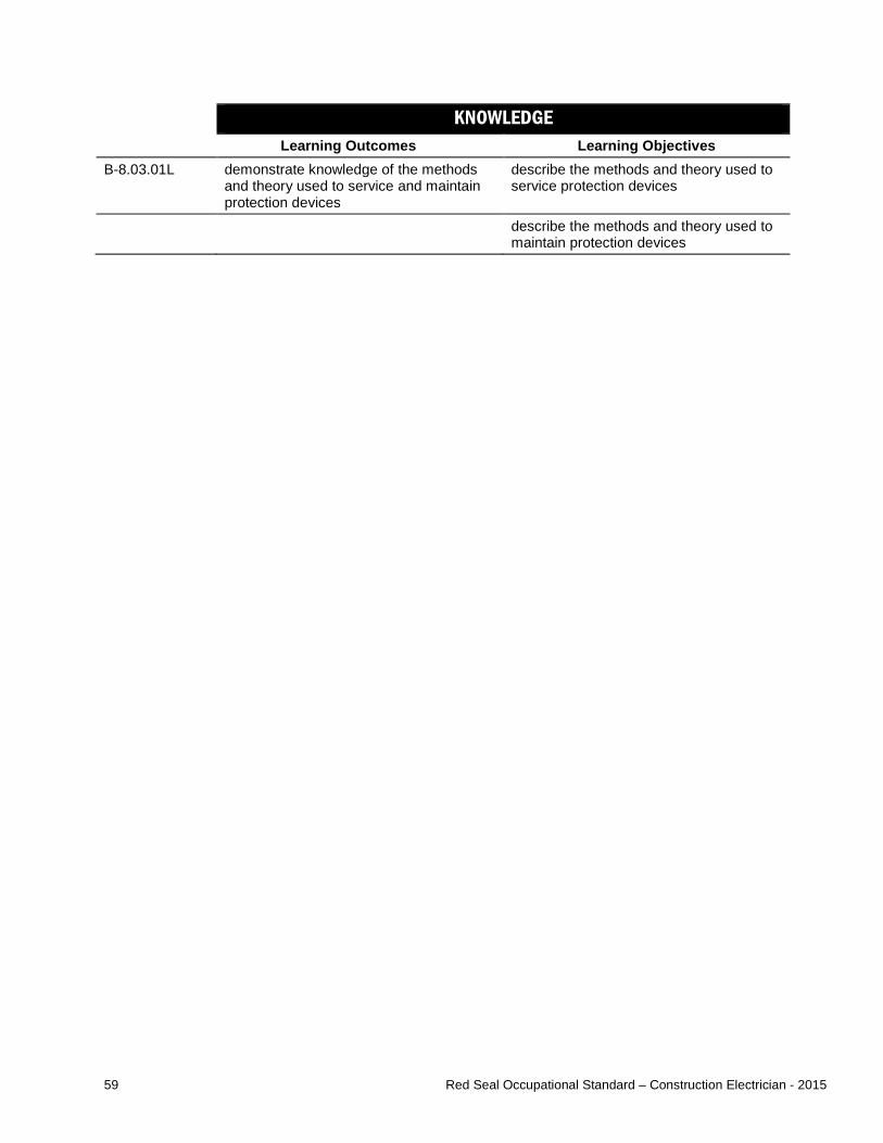
59 Red Seal Occupational Standard – Construction Electrician - 2015
KNOWLEDGE Learning Outcomes Learning Objectives
B-8.03.01L demonstrate knowledge of the methods and theory used to service and maintain protection devices
describe the methods and theory used to service protection devices
describe the methods and theory used to maintain protection devices
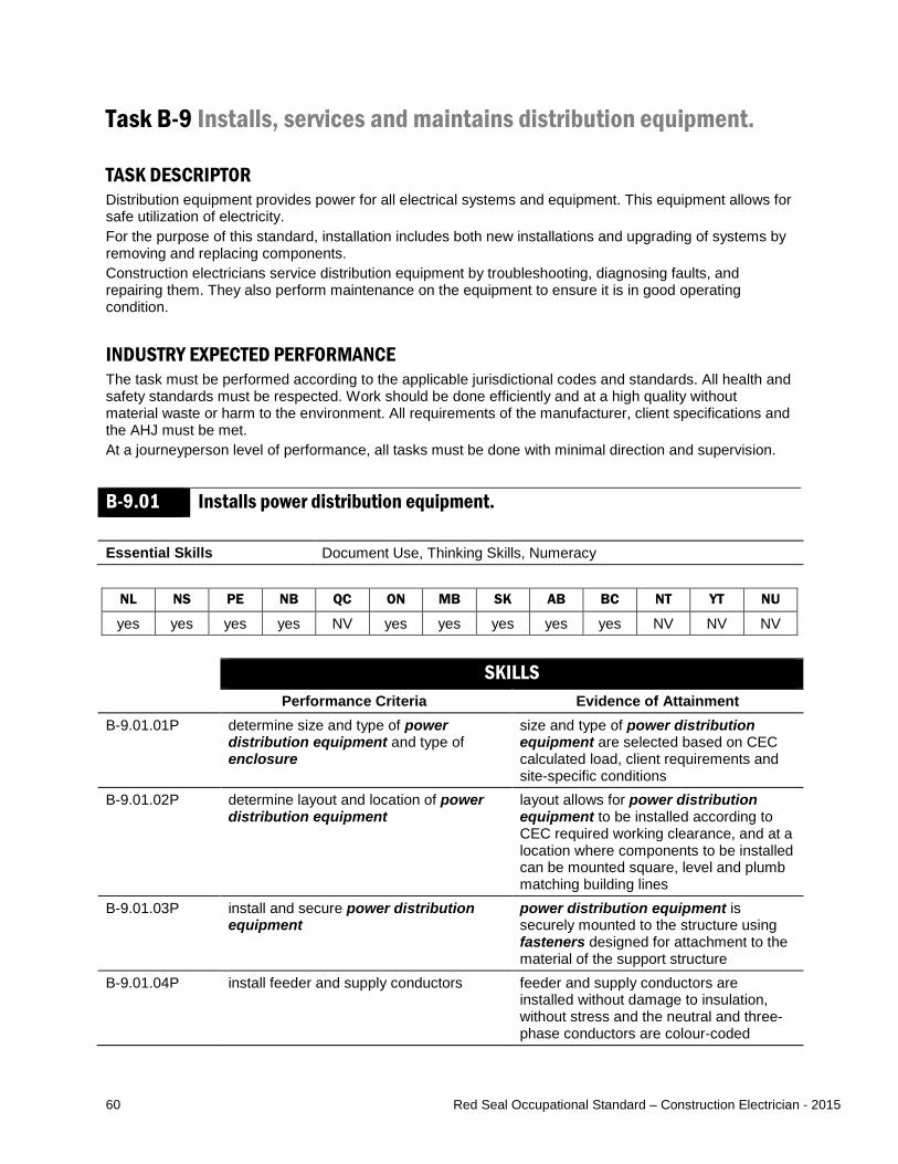
60 Red Seal Occupational Standard – Construction Electrician - 2015
Task B-9 Installs, services and maintains distribution equipment. TASK DESCRIPTOR Distribution equipment provides power for all electrical systems and equipment. This equipment allows for safe utilization of electricity. For the purpose of this standard, installation includes both new installations and upgrading of systems by removing and replacing components. Construction electricians service distribution equipment by troubleshooting, diagnosing faults, and repairing them. They also perform maintenance on the equipment to ensure it is in good operating condition. INDUSTRY EXPECTED PERFORMANCE The task must be performed according to the applicable jurisdictional codes and standards. All health and safety standards must be respected. Work should be done efficiently and at a high quality without material waste or harm to the environment. All requirements of the manufacturer, client specifications and the AHJ must be met. At a journeyperson level of performance, all tasks must be done with minimal direction and supervision. B-9.01 Installs power distribution equipment. Essential Skills Document Use, Thinking Skills, Numeracy
NL NS PE NB QC ON MB SK AB BC NT YT NU
yes yes yes yes NV yes yes yes yes yes NV NV NV SKILLS
Performance Criteria Evidence of Attainment B-9.01.01P determine size and type of power
distribution equipment and type of enclosure
size and type of power distribution equipment are selected based on CEC calculated load, client requirements and site-specific conditions
B-9.01.02P determine layout and location of power distribution equipment
layout allows for power distribution equipment to be installed according to CEC required working clearance, and at a location where components to be installed can be mounted square, level and plumb matching building lines
B-9.01.03P install and secure power distribution equipment
power distribution equipment is securely mounted to the structure using fasteners designed for attachment to the material of the support structure
B-9.01.04P install feeder and supply conductors feeder and supply conductors are installed without damage to insulation, without stress and the neutral and three-phase conductors are colour-coded

61 Red Seal Occupational Standard – Construction Electrician - 2015
B-9.01.05P terminate feeder and supply conductor connections
conductors are tightened and secured, and insulation is removed according to manufacturers’ specifications, and antioxidant is applied where required
B-9.01.06P conduct tests of power distribution equipment and feeders
power distribution equipment and feeders are functional and connected to match the application requirements
B-9.01.07P identify information on power distribution equipment
power distribution equipment is labelled according to job and client requirements
B-9.01.08P remove and dispose of existing power distribution equipment when replacing and update documentation
all used power distribution equipment, enclosures, feeder and supply conductors are disposed of according to local codes and waste disposal requirements
RANGE OF VARIABLES power distribution equipment includes: panels, sub-panels, power distribution centres (PDC), switchboards, breakers, fuses, disconnects, racking equipment, CTs, PTs, busbars, splitters, MCCs enclosures include: CSA / NEMA type designation, hazardous locations (as defined by the Markings of Section 18 of the CEC) fasteners include: screws, straps, inserts, anchors, wedge clamps, seismic restraints, insulators KNOWLEDGE
Learning Outcomes Learning Objectives B-9.01.01L demonstrate knowledge of power
distribution equipment, their applications and operation
interpret codes and regulations pertaining to power distribution equipment
interpret information pertaining to power distribution equipment found on drawings and specifications
identify types of power distribution equipment and describe their characteristics and applications
identify the considerations and requirements for selecting power distribution equipment and enclosures
B-9.01.02L demonstrate knowledge of the procedures used to install power distribution equipment
describe the procedures used to install power distribution equipment
describe the procedures used to connect power distribution equipment
describe procedures for transporting and moving electrical equipment
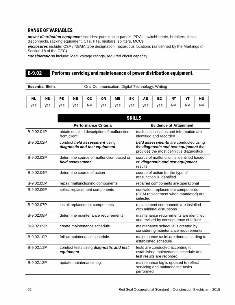
62 Red Seal Occupational Standard – Construction Electrician - 2015
RANGE OF VARIABLES power distribution equipment includes: panels, sub-panels, PDCs, switchboards, breakers, fuses, disconnects, racking equipment, CTs, PTs, busbars, splitters, MCCs enclosures include: CSA / NEMA type designation, hazardous locations (as defined by the Markings of Section 18 of the CEC) considerations include: load, voltage ratings, required circuit capacity
B-9.02 Performs servicing and maintenance of power distribution equipment. Essential Skills Oral Communication, Digital Technology, Writing
NL NS PE NB QC ON MB SK AB BC NT YT NU
yes yes yes yes NV yes yes yes yes yes NV NV NV SKILLS
Performance Criteria Evidence of Attainment B-9.02.01P obtain detailed description of malfunction
from client malfunction issues and information are identified and recorded
B-9.02.02P conduct field assessment using diagnostic and test equipment
field assessments are conducted using the diagnostic and test equipment that provides the most definitive diagnostics
B-9.02.03P determine source of malfunction based on field assessment
source of malfunction is identified based on diagnostic and test equipment results
B-9.02.04P determine course of action course of action for the type of malfunction is identified
B-9.02.05P repair malfunctioning components repaired components are operational B-9.02.06P select replacement components equivalent replacement components
(OEM replacement when mandated) are selected
B-9.02.07P install replacement components replacement components are installed with minimal disruptions
B-9.02.08P determine maintenance requirements maintenance requirements are identified and revised by consequence of failure
B-9.02.09P create maintenance schedule maintenance schedule is created by considering maintenance requirements
B-9.02.10P follow maintenance schedule maintenance tasks are done according to established schedule
B-9.02.11P conduct tests using diagnostic and test equipment
tests are conducted according to established maintenance schedule and test results are recorded
B-9.02.12P update maintenance log maintenance log is updated to reflect servicing and maintenance tasks performed
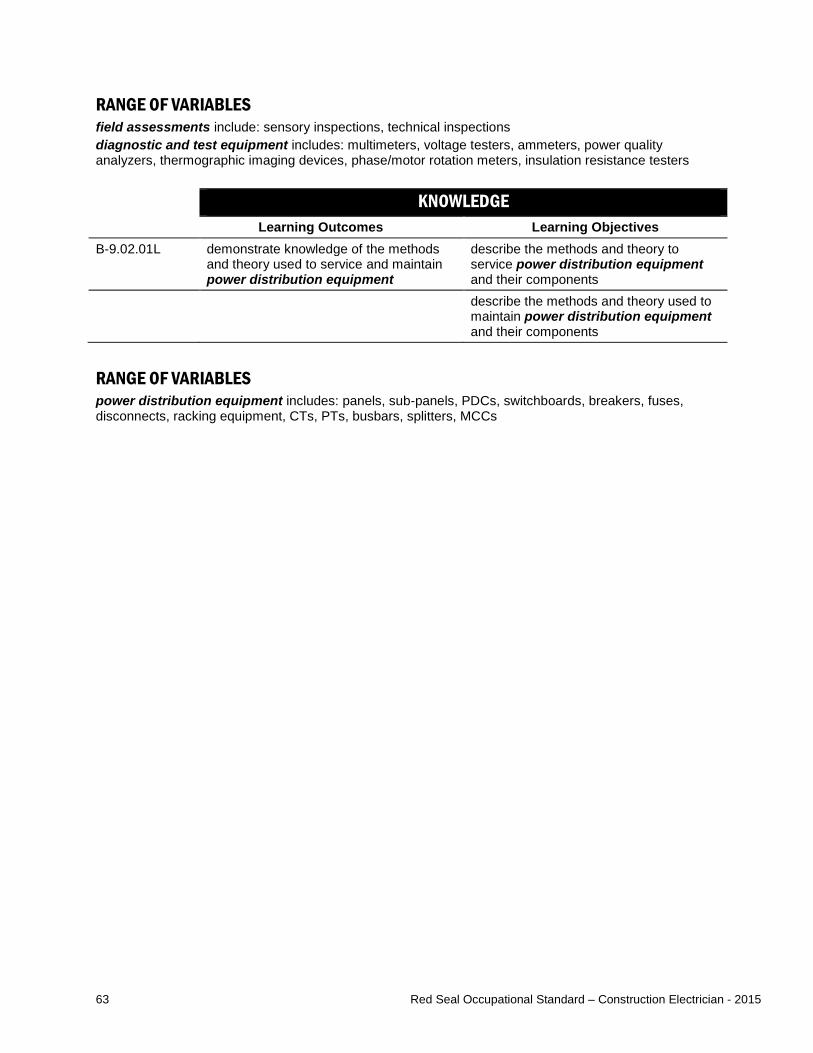
63 Red Seal Occupational Standard – Construction Electrician - 2015
RANGE OF VARIABLES field assessments include: sensory inspections, technical inspections diagnostic and test equipment includes: multimeters, voltage testers, ammeters, power quality analyzers, thermographic imaging devices, phase/motor rotation meters, insulation resistance testers KNOWLEDGE
Learning Outcomes Learning Objectives B-9.02.01L demonstrate knowledge of the methods
and theory used to service and maintain power distribution equipment
describe the methods and theory to service power distribution equipment and their components
describe the methods and theory used to maintain power distribution equipment and their components
RANGE OF VARIABLES power distribution equipment includes: panels, sub-panels, PDCs, switchboards, breakers, fuses, disconnects, racking equipment, CTs, PTs, busbars, splitters, MCCs
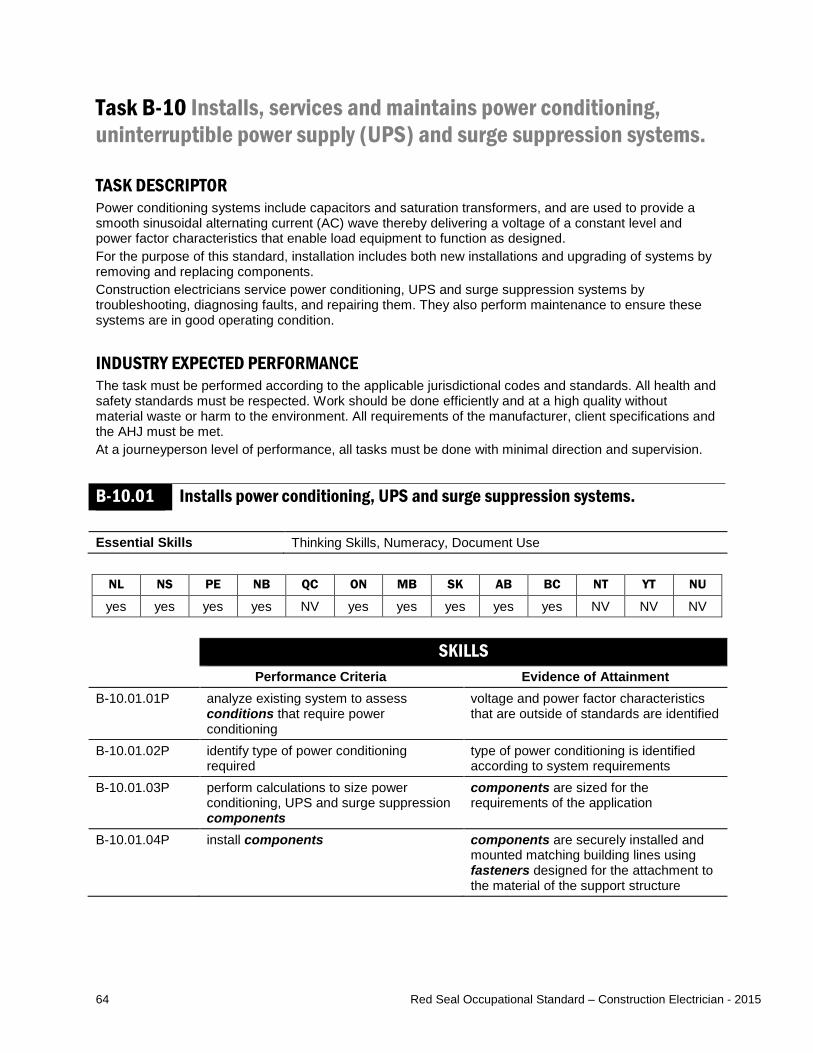
64 Red Seal Occupational Standard – Construction Electrician - 2015
Task B-10 Installs, services and maintains power conditioning, uninterruptible power supply (UPS) and surge suppression systems.
TASK DESCRIPTOR Power conditioning systems include capacitors and saturation transformers, and are used to provide a smooth sinusoidal alternating current (AC) wave thereby delivering a voltage of a constant level and power factor characteristics that enable load equipment to function as designed. For the purpose of this standard, installation includes both new installations and upgrading of systems by removing and replacing components. Construction electricians service power conditioning, UPS and surge suppression systems by troubleshooting, diagnosing faults, and repairing them. They also perform maintenance to ensure these systems are in good operating condition. INDUSTRY EXPECTED PERFORMANCE The task must be performed according to the applicable jurisdictional codes and standards. All health and safety standards must be respected. Work should be done efficiently and at a high quality without material waste or harm to the environment. All requirements of the manufacturer, client specifications and the AHJ must be met. At a journeyperson level of performance, all tasks must be done with minimal direction and supervision. B-10.01 Installs power conditioning, UPS and surge suppression systems. Essential Skills Thinking Skills, Numeracy, Document Use
NL NS PE NB QC ON MB SK AB BC NT YT NU
yes yes yes yes NV yes yes yes yes yes NV NV NV SKILLS
Performance Criteria Evidence of Attainment B-10.01.01P analyze existing system to assess
conditions that require power conditioning
voltage and power factor characteristics that are outside of standards are identified
B-10.01.02P identify type of power conditioning required
type of power conditioning is identified according to system requirements
B-10.01.03P perform calculations to size power conditioning, UPS and surge suppression components
components are sized for the requirements of the application
B-10.01.04P install components components are securely installed and mounted matching building lines using fasteners designed for the attachment to the material of the support structure

65 Red Seal Occupational Standard – Construction Electrician - 2015
B-10.01.05P terminate and interconnect components components are terminated and interconnected according to electrical drawings and specifications, job and CEC requirements (for example, conductors secure with no insulation compromised and not pinched)
B-10.01.06P analyze system output to ensure effectiveness of power conditioning installation
test results reflect improved power quality
B-10.01.07P conduct tests of power conditioning, UPS and surge suppression after installation and record results
power conditioning, UPS and surge suppression is functional and connected to match the application requirements
B-10.01.08P remove existing power conditioning and UPS components when replacing and update documentation
equipment is removed with minimal impact to the environment and drawings reflect operational changes
RANGE OF VARIABLES conditions include: harmonics, power factor correction, transient voltages and current, induced frequencies components include: batteries, transformers, capacitors, shunt coils, diodes, synchronous condensers (motors) and filters fasteners include: screws, straps, inserts, anchors, wedge clamps, seismic restraints, insulators KNOWLEDGE
Learning Outcomes Learning Objectives B-10.01.01L demonstrate knowledge of types of power
conditioning, UPS and surge suppression systems and their applications
interpret codes and regulations pertaining to power conditioning, UPS and surge suppression systems
explain power quality and its impact on equipment operation
explain single-phase and three-phase power factor correction and its associated calculations
identify the types of power factor correction equipment and describe their characteristics, applications and operation
identify equipment used to reduce harmonics in power distribution systems and describe their characteristics, applications and operation
identify surge suppression equipment used in power distribution system conditioning and describe their characteristics, applications and operation
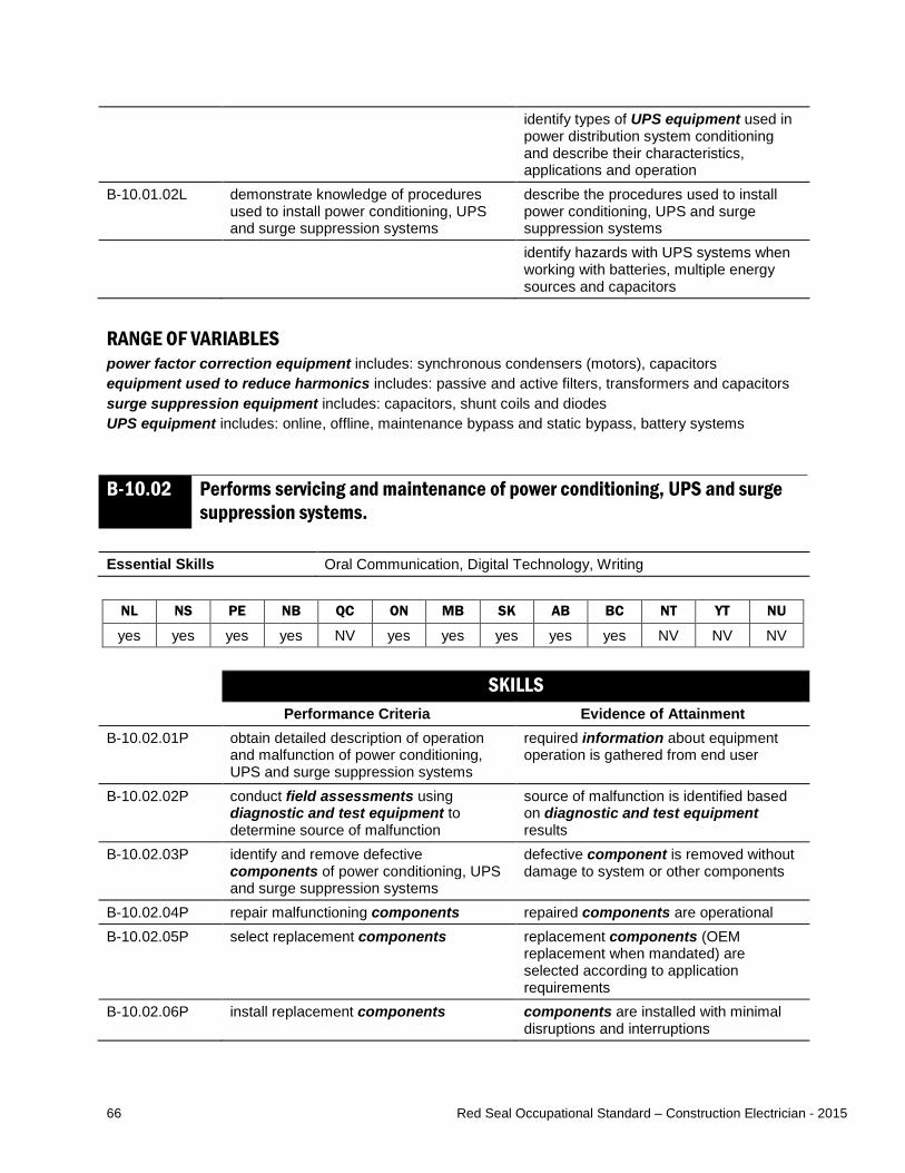
66 Red Seal Occupational Standard – Construction Electrician - 2015
identify types of UPS equipment used in power distribution system conditioning and describe their characteristics, applications and operation
B-10.01.02L demonstrate knowledge of procedures used to install power conditioning, UPS and surge suppression systems
describe the procedures used to install power conditioning, UPS and surge suppression systems
identify hazards with UPS systems when working with batteries, multiple energy sources and capacitors
RANGE OF VARIABLES power factor correction equipment includes: synchronous condensers (motors), capacitors equipment used to reduce harmonics includes: passive and active filters, transformers and capacitors surge suppression equipment includes: capacitors, shunt coils and diodes UPS equipment includes: online, offline, maintenance bypass and static bypass, battery systems
B-10.02 Performs servicing and maintenance of power conditioning, UPS and surge suppression systems.
Essential Skills Oral Communication, Digital Technology, Writing
NL NS PE NB QC ON MB SK AB BC NT YT NU
yes yes yes yes NV yes yes yes yes yes NV NV NV SKILLS
Performance Criteria Evidence of Attainment B-10.02.01P obtain detailed description of operation
and malfunction of power conditioning, UPS and surge suppression systems
required information about equipment operation is gathered from end user
B-10.02.02P conduct field assessments using diagnostic and test equipment to determine source of malfunction
source of malfunction is identified based on diagnostic and test equipment results
B-10.02.03P identify and remove defective components of power conditioning, UPS and surge suppression systems
defective component is removed without damage to system or other components
B-10.02.04P repair malfunctioning components repaired components are operational B-10.02.05P select replacement components replacement components (OEM
replacement when mandated) are selected according to application requirements
B-10.02.06P install replacement components components are installed with minimal disruptions and interruptions

67 Red Seal Occupational Standard – Construction Electrician - 2015
B-10.02.07P conduct tests of power conditioning, UPS and surge suppression systems after repair
power conditioning, UPS and surge suppression systems are functional and connected to match the application requirements
B-10.02.08P clean, lubricate and adjust components power conditioning, UPS and surge suppression system components are restored to optimal conditions
B-10.02.09P record tests in maintenance schedule operational problems are identified in maintenance schedule data with detailed notations
B-10.02.10P compare and analyze maintenance test results
maintenance is performed when required based on analysis of test results and comparison with specifications
RANGE OF VARIABLES end user information includes: log books, manufacturers’ manuals, standard operating procedures, anecdotal details from maintenance personnel field assessments include: sensory inspections, technical inspections components include: batteries, transformers, capacitors, shunt coils, diodes, synchronous condensers (motors) and filters diagnostic and test equipment include: battery load testers, multimeters, voltmeters, ammeters, power quality analyzers, oscilloscopes, thermographic imaging devices components include: batteries, transformers, capacitors, shunt coils, diodes, synchronous condensers (motors) and filters cleaning lubricating and adjusting procedures include: cleaning fans and filters, lubricating bearings and bushings, load testing batteries, adjusting cabinets and door seals KNOWLEDGE
Learning Outcomes Learning Objectives B-10.02.01L demonstrate knowledge of types of power
conditioning, UPS and surge suppression systems and their applications
interpret codes and regulations pertaining to power conditioning, UPS and surge suppression systems
explain power quality and its impact on equipment operation
explain single-phase and three-phase power factor correction and its associated calculations
identify the types of power factor correction equipment and describe their characteristics, applications and operation
identify equipment used to reduce harmonics in power distribution systems and describe their characteristics, applications and operation
identify surge suppression equipment used in power distribution system conditioning and describe their characteristics, applications and operation
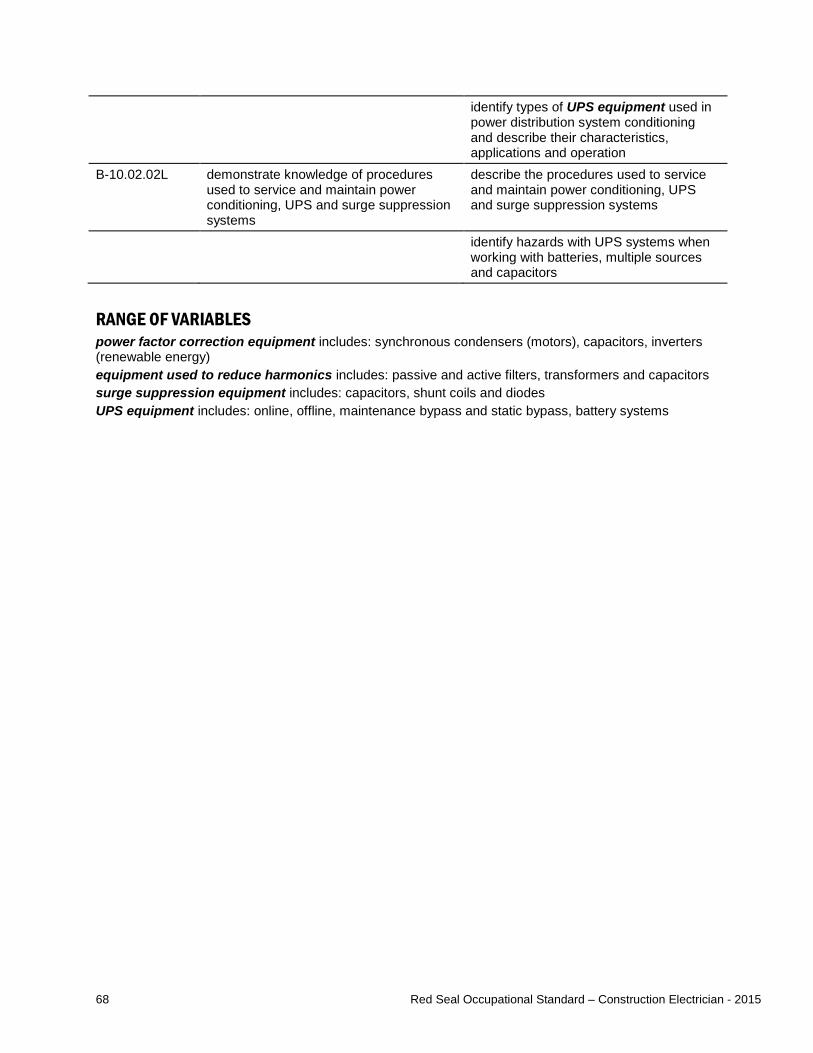
68 Red Seal Occupational Standard – Construction Electrician - 2015
identify types of UPS equipment used in power distribution system conditioning and describe their characteristics, applications and operation
B-10.02.02L demonstrate knowledge of procedures used to service and maintain power conditioning, UPS and surge suppression systems
describe the procedures used to service and maintain power conditioning, UPS and surge suppression systems
identify hazards with UPS systems when working with batteries, multiple sources and capacitors
RANGE OF VARIABLES power factor correction equipment includes: synchronous condensers (motors), capacitors, inverters (renewable energy) equipment used to reduce harmonics includes: passive and active filters, transformers and capacitors surge suppression equipment includes: capacitors, shunt coils and diodes UPS equipment includes: online, offline, maintenance bypass and static bypass, battery systems

69 Red Seal Occupational Standard – Construction Electrician - 2015
Task B-11 Installs, services and maintains bonding and grounding protection systems. TASK DESCRIPTOR Bonding and grounding systems are used to protect life and equipment from transient and fault current. Ground fault protection systems are used to protect against electrical current leakage, which could result in electrical shock or equipment malfunctions. For the purpose of this standard, installation includes both new installations and upgrading of systems by removing and replacing components. Construction electricians service bonding and grounding protection systems by troubleshooting, diagnosing faults, and repairing them. They also perform maintenance to ensure these systems are in good operating condition. INDUSTRY EXPECTED PERFORMANCE The task must be performed according to the applicable jurisdictional codes and standards. All health and safety standards must be respected. Work should be done efficiently and at a high quality without material waste or harm to the environment. All requirements of the manufacturer, client specifications and the AHJ must be met. At a journeyperson level of performance, all tasks must be done with minimal direction and supervision. B-11.01 Installs grounding and bonding systems. Essential Skills Digital Technology, Document Use, Reading
NL NS PE NB QC ON MB SK AB BC NT YT NU
yes yes yes yes NV yes yes yes yes yes NV NV NV SKILLS
Performance Criteria Evidence of Attainment B-11.01.01P determine type of grounding electrodes grounding electrodes are determined
based on site-specific conditions and engineering specifications
B-11.01.02P determine ground conductor size conductor size is determined based on supply voltage and CEC requirements
B-11.01.03P determine layout and location of grounding system components
layout allows for the most efficient installation of grounding electrodes, routing of the grounding conductor, and point of termination at the source of supply and/or service equipment
B-11.01.04P install grounding system components grounding system components are installed according to layout and site conditions
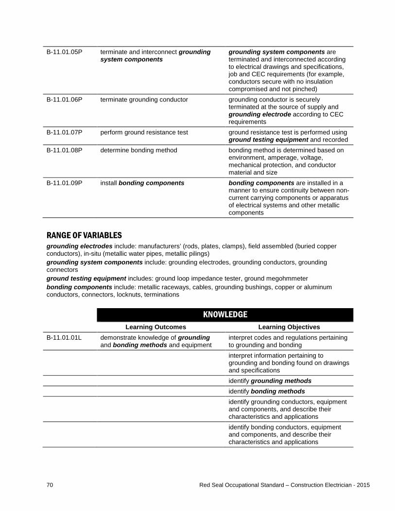
70 Red Seal Occupational Standard – Construction Electrician - 2015
B-11.01.05P terminate and interconnect grounding system components
grounding system components are terminated and interconnected according to electrical drawings and specifications, job and CEC requirements (for example, conductors secure with no insulation compromised and not pinched)
B-11.01.06P terminate grounding conductor grounding conductor is securely terminated at the source of supply and grounding electrode according to CEC requirements
B-11.01.07P perform ground resistance test ground resistance test is performed using ground testing equipment and recorded
B-11.01.08P determine bonding method bonding method is determined based on environment, amperage, voltage, mechanical protection, and conductor material and size
B-11.01.09P install bonding components bonding components are installed in a manner to ensure continuity between non-current carrying components or apparatus of electrical systems and other metallic components
RANGE OF VARIABLES grounding electrodes include: manufacturers’ (rods, plates, clamps), field assembled (buried copper conductors), in-situ (metallic water pipes, metallic pilings) grounding system components include: grounding electrodes, grounding conductors, grounding connectors ground testing equipment includes: ground loop impedance tester, ground megohmmeter bonding components include: metallic raceways, cables, grounding bushings, copper or aluminum conductors, connectors, locknuts, terminations KNOWLEDGE
Learning Outcomes Learning Objectives B-11.01.01L demonstrate knowledge of grounding
and bonding methods and equipment interpret codes and regulations pertaining to grounding and bonding
interpret information pertaining to grounding and bonding found on drawings and specifications
identify grounding methods identify bonding methods identify grounding conductors, equipment
and components, and describe their characteristics and applications
identify bonding conductors, equipment and components, and describe their characteristics and applications
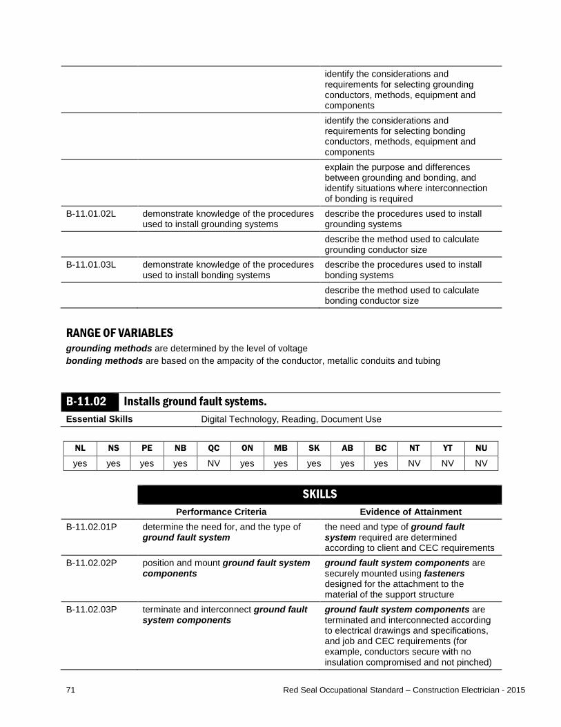
71 Red Seal Occupational Standard – Construction Electrician - 2015
identify the considerations and requirements for selecting grounding conductors, methods, equipment and components
identify the considerations and requirements for selecting bonding conductors, methods, equipment and components
explain the purpose and differences between grounding and bonding, and identify situations where interconnection of bonding is required
B-11.01.02L demonstrate knowledge of the procedures used to install grounding systems
describe the procedures used to install grounding systems
describe the method used to calculate grounding conductor size
B-11.01.03L demonstrate knowledge of the procedures used to install bonding systems
describe the procedures used to install bonding systems
describe the method used to calculate bonding conductor size
RANGE OF VARIABLES grounding methods are determined by the level of voltage bonding methods are based on the ampacity of the conductor, metallic conduits and tubing
B-11.02 Installs ground fault systems. Essential Skills Digital Technology, Reading, Document Use
NL NS PE NB QC ON MB SK AB BC NT YT NU
yes yes yes yes NV yes yes yes yes yes NV NV NV SKILLS
Performance Criteria Evidence of Attainment B-11.02.01P determine the need for, and the type of
ground fault system the need and type of ground fault system required are determined according to client and CEC requirements
B-11.02.02P position and mount ground fault system components
ground fault system components are securely mounted using fasteners designed for the attachment to the material of the support structure
B-11.02.03P terminate and interconnect ground fault system components
ground fault system components are terminated and interconnected according to electrical drawings and specifications, and job and CEC requirements (for example, conductors secure with no insulation compromised and not pinched)
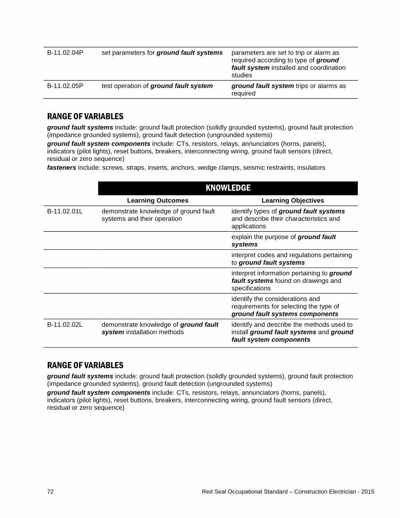
72 Red Seal Occupational Standard – Construction Electrician - 2015
B-11.02.04P set parameters for ground fault systems parameters are set to trip or alarm as required according to type of ground fault system installed and coordination studies
B-11.02.05P test operation of ground fault system ground fault system trips or alarms as required
RANGE OF VARIABLES ground fault systems include: ground fault protection (solidly grounded systems), ground fault protection (impedance grounded systems), ground fault detection (ungrounded systems) ground fault system components include: CTs, resistors, relays, annunciators (horns, panels), indicators (pilot lights), reset buttons, breakers, interconnecting wiring, ground fault sensors (direct, residual or zero sequence) fasteners include: screws, straps, inserts, anchors, wedge clamps, seismic restraints, insulators KNOWLEDGE
Learning Outcomes Learning Objectives B-11.02.01L demonstrate knowledge of ground fault
systems and their operation identify types of ground fault systems and describe their characteristics and applications
explain the purpose of ground fault systems
interpret codes and regulations pertaining to ground fault systems
interpret information pertaining to ground fault systems found on drawings and specifications
identify the considerations and requirements for selecting the type of ground fault systems components
B-11.02.02L
demonstrate knowledge of ground fault system installation methods
identify and describe the methods used to install ground fault systems and ground fault system components
RANGE OF VARIABLES ground fault systems include: ground fault protection (solidly grounded systems), ground fault protection (impedance grounded systems), ground fault detection (ungrounded systems) ground fault system components include: CTs, resistors, relays, annunciators (horns, panels), indicators (pilot lights), reset buttons, breakers, interconnecting wiring, ground fault sensors (direct, residual or zero sequence)

73 Red Seal Occupational Standard – Construction Electrician - 2015
B-11.03 Installs lightning protection systems. Essential Skills Thinking Skills, Reading, Document Use
NL NS PE NB QC ON MB SK AB BC NT YT NU
yes yes yes yes NV yes yes yes yes yes NV NV NV SKILLS
Performance Criteria Evidence of Attainment B-11.03.01P determine the need for, and the type of
lightning protection system required the need and type of lightning protection system required is determined subject to type and use of structure, and AHJ and client requirements
B-11.03.02P select and lay out lightning protection components
layout allows for lightning protection components to be installed in a manner to direct lightning energy to ground
B-11.03.03P position and mount lightning protection components
lightning protection components are securely mounted using fasteners designed for attachment to the material of the support structure
B-11.03.04P terminate and interconnect lightning protection components
lightning protection components are terminated and interconnected according to electrical drawings and specifications, and job and CEC requirements (for example, conductors are installed in smooth sweeping curves)
B-11.03.05P remove and dispose of existing lightning protection components when replacing and update documentation
all used lightning protection components are disposed of according to local codes and waste disposal requirements
B-11.03.06P verify installation visual inspection of component installation is performed to ensure interconnection requirements are met
RANGE OF VARIABLES lightning protection systems include: lightning arrester protection, structure protection lightning protection components include: lightning rod (air terminal), intercepting conductors, down conductors, ground electrodes (ground rods), supports, lightning arresters fasteners include: screws, straps, inserts, anchors, wedge clamps, insulators
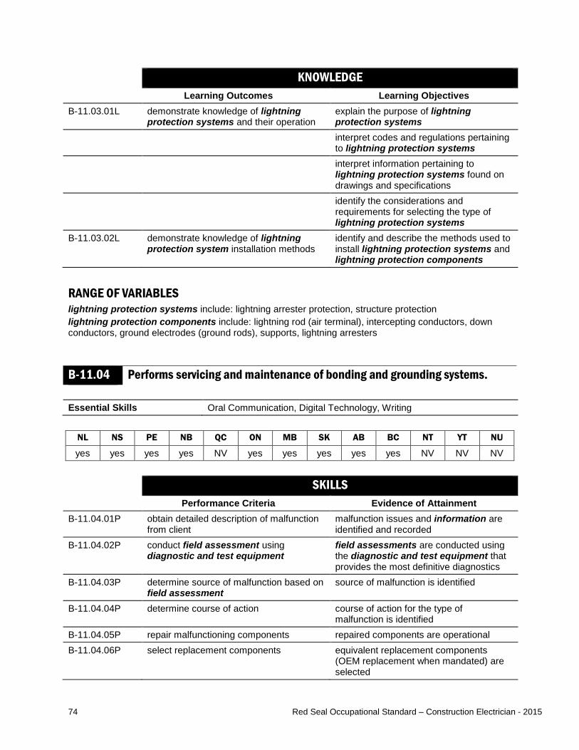
74 Red Seal Occupational Standard – Construction Electrician - 2015
KNOWLEDGE Learning Outcomes Learning Objectives
B-11.03.01L demonstrate knowledge of lightning protection systems and their operation
explain the purpose of lightning protection systems
interpret codes and regulations pertaining to lightning protection systems
interpret information pertaining to lightning protection systems found on drawings and specifications
identify the considerations and requirements for selecting the type of lightning protection systems
B-11.03.02L demonstrate knowledge of lightning protection system installation methods
identify and describe the methods used to install lightning protection systems and lightning protection components
RANGE OF VARIABLES lightning protection systems include: lightning arrester protection, structure protection lightning protection components include: lightning rod (air terminal), intercepting conductors, down conductors, ground electrodes (ground rods), supports, lightning arresters
B-11.04 Performs servicing and maintenance of bonding and grounding systems. Essential Skills Oral Communication, Digital Technology, Writing
NL NS PE NB QC ON MB SK AB BC NT YT NU
yes yes yes yes NV yes yes yes yes yes NV NV NV SKILLS
Performance Criteria Evidence of Attainment B-11.04.01P obtain detailed description of malfunction
from client malfunction issues and information are identified and recorded
B-11.04.02P conduct field assessment using diagnostic and test equipment
field assessments are conducted using the diagnostic and test equipment that provides the most definitive diagnostics
B-11.04.03P determine source of malfunction based on field assessment
source of malfunction is identified
B-11.04.04P determine course of action course of action for the type of malfunction is identified
B-11.04.05P repair malfunctioning components repaired components are operational B-11.04.06P select replacement components equivalent replacement components
(OEM replacement when mandated) are selected

75 Red Seal Occupational Standard – Construction Electrician - 2015
B-11.04.07P install replacement components replacement components are installed with minimal disruptions
B-11.04.08P determine maintenance requirements maintenance requirements are identified by consequence of failure
B-11.04.09P create maintenance schedule maintenance schedule is created by considering maintenance requirements
B-11.04.10P follow maintenance schedule maintenance tasks are done according to established schedule
B-11.04.11P conduct tests using diagnostic and test equipment
tests are conducted according to established maintenance schedule, and test results are recorded
B-11.04.12P update maintenance log maintenance log is updated to reflect servicing and maintenance tasks performed
RANGE OF VARIABLES information includes: log books, manufacturers’ manuals, standard operating procedures, anecdotal details from maintenance personnel field assessments include: sensory inspections, technical inspections diagnostic and test equipment includes: multimeters, voltage testers, ammeters, insulation resistance testers KNOWLEDGE
Learning Outcomes Learning Objectives B-11.04.01L demonstrate knowledge of the methods
used to service and maintain bonding and grounding and associated protection systems
describe the methods used to service bonding and grounding and associated protection systems, and their components
describe the methods used to maintain bonding and grounding and associated protection systems, and their components

76 Red Seal Occupational Standard – Construction Electrician - 2015
Task B-12 Installs, services and maintains power generation systems.
TASK DESCRIPTOR The purpose of generators is to convert kinetic energy into electricity. They can be used when power from the utility is unavailable or the building is isolated from the power grid. For the purpose of this standard, installation includes both new installations and upgrading of systems by removing and replacing components. Construction electricians service power generating systems by troubleshooting, diagnosing faults, and repairing them. They also perform maintenance to ensure these systems are in good operating condition. INDUSTRY EXPECTED PERFORMANCE The task must be performed according to the applicable jurisdictional codes and standards. All health and safety standards must be respected. Work should be done efficiently and at a high quality without material waste or harm to the environment. All requirements of the manufacturer, client specifications and the AHJ must be met. At a journeyperson level of performance, all tasks must be done with minimal direction and supervision. B-12.01 Installs alternating current (AC) generating systems. Essential Skills Numeracy, Document Use, Thinking Skills
NL NS PE NB QC ON MB SK AB BC NT YT NU
yes yes yes yes NV yes yes yes yes yes NV NV NV SKILLS
Performance Criteria Evidence of Attainment B-12.01.01P determine power requirements for the
application by performing load calculations and tests
power requirements are determined using connected load
B-12.01.02P determine the type and capacity of AC generating system and components to be installed for the application
type and capacity of AC generating systems and components meet the established requirements
B-12.01.03P position and mount AC generating systems and components
AC generating system is positioned to account for ventilation according to manufacturers’ and job specifications and AHJ requirements
B-12.01.04P terminate and interconnect AC generating systems and components
AC generating systems and components are terminated and interconnected according to electrical drawings and specifications, job and CEC requirements (for example, conductors secure with no insulation compromised and not pinched)

77 Red Seal Occupational Standard – Construction Electrician - 2015
B-12.01.05P ground or bond AC generating systems and components
AC generating system and components are grounded and bonded using a conductor sized according to CEC requirements
B-12.01.06P program AC generating systems and controls for startup and shutdown sequences
programming of AC generating system meets functionality and established parameters and test results are documented
B-12.01.07P conduct tests of AC generating systems and AC generating system components after installation, make required adjustments to ensure required voltage and frequency, and record results
AC generating systems and AC generating system components are functional and connected according to the job specification, AHJ and CEC requirements, and test results are recorded
B-12.01.08P disconnect existing AC generating systems and AC generating system components, ensure safety of remaining installation and update documentation
AC generating systems and AC generating system components are disconnected, remaining installations are terminated according to CEC requirements and documentation is updated
RANGE OF VARIABLES AC generating systems include: single-phase, three-phase, portable, stationary, manually operated, automatically operated AC generating system components include: shaft, armature and stator, bearings, frame, exciter windings, transfer switch, prime mover, cables, conductors, overcurrent devices, overload devices, fuel storage, Automatic Voltage Regulator (AVR) KNOWLEDGE
Learning Outcomes Learning Objectives B-12.01.01L demonstrate knowledge of AC
generating systems and AC generating system components, their applications and operation
describe the components of AC generating systems and explain their operating principles
identify types of AC generating systems and describe their characteristics and applications
identify AC generating system components and describe their characteristics and applications
identify the considerations and requirements for selecting AC generating systems and AC generating system components
interpret information pertaining to AC generating systems found on drawings and specifications
interpret codes, standards and regulations pertaining to AC generating systems

78 Red Seal Occupational Standard – Construction Electrician - 2015
B-12.01.02L demonstrate knowledge of the procedures used to install and connect AC generating systems
describe the procedures used to install AC generating systems and AC generating system components
describe the procedures used to connect AC generating systems and AC generating system components
describe the procedures used to control the output voltage, phase sequencing and frequency of AC generators
RANGE OF VARIABLES AC generating systems include: single-phase, three-phase, portable, stationary, manually operated, automatically operated AC generating system components include: shaft, armature and stator, bearings, frame, exciter windings, transfer switch, prime mover, cables, conductors, overcurrent devices, overload devices, fuel storage, AVR
B-12.02 Performs servicing and maintenance of AC generating systems. Essential Skills Oral Communication, Digital Technology, Document Use
NL NS PE NB QC ON MB SK AB BC NT YT NU
yes yes yes yes NV yes yes yes yes yes NV NV NV SKILLS
Performance Criteria Evidence of Attainment B-12.02.01P obtain detailed description of operation
and malfunction of AC generating system
required information about equipment operation is gathered from end user
B-12.02.02P conduct field assessments using diagnostic and test equipment to determine source of malfunction
source of malfunction is identified based on inspection and diagnostic equipment and test equipment results
B-12.02.03P identify and remove defective AC generating system components
defective component is removed without damage to system or other components
B-12.02.04P repair malfunctioning components repaired components are operational B-12.02.05P select replacement components replacement components (OEM
replacement when mandated) are selected according to the application
B-12.02.06P install replacement components components are installed with minimal disruptions and interruptions
B-12.02.07P conduct tests of AC generating systems after repair
AC generating system is connected according to manufacturers’ specifications, CEC requirements and the direction of rotation according to specifications

79 Red Seal Occupational Standard – Construction Electrician - 2015
B-12.02.08P perform service procedures to AC generating system components
AC generating system components are restored to optimal conditions
B-12.02.09P record tests in maintenance schedule maintenance log is updated to reflect servicing and maintenance tasks performed
B-12.02.10P compare and analyze maintenance test results
maintenance is performed when required based on analysis of test results and comparison with specifications
RANGE OF VARIABLES AC generating systems include: single-phase, three-phase, portable, stationary, manually operated, automatically operated field assessments include: sensory inspections, technical inspections diagnostic and test equipment includes: multimeters, voltage testers, ammeters, oscilloscope, power quality analyzers, high pot tester, thermographic imaging devices, phase rotation meters, insulation resistance testers, ground loop tester AC generating system components include: shaft, armature and stator, bearings, frame, exciter windings, transfer switch, prime mover, cables, conductors, overcurrent devices, overload devices, fuel storage, Automatic Voltage Regulator (AVR) service procedures include: cleaning cooling fans, adjusting belt tensioners, lubricating bearings and bushings, cleaning switches KNOWLEDGE
Learning Outcomes Learning Objectives B-12.02.01L demonstrate knowledge of AC
generating systems, their applications and operation
identify types of AC generating systems and describe their characteristics
identify AC generating system components and describe their applications
interpret codes and regulations pertaining to AC generating systems
interpret information pertaining to AC generating systems found on drawings and specifications
explain the components and operating principles of AC generating systems
interpret information contained on AC generator nameplates
B-12.02.02L demonstrate knowledge of procedures used to service and maintain AC generating systems
describe the procedures used to service AC generating systems and their components
describe the procedures used to maintain AC generating systems and their components
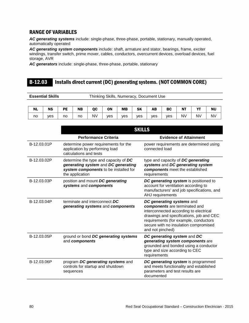
80 Red Seal Occupational Standard – Construction Electrician - 2015
RANGE OF VARIABLES AC generating systems include: single-phase, three-phase, portable, stationary, manually operated, automatically operated AC generating system components include: shaft, armature and stator, bearings, frame, exciter windings, transfer switch, prime mover, cables, conductors, overcurrent devices, overload devices, fuel storage, AVR AC generators include: single-phase, three-phase, portable, stationary
B-12.03 Installs direct current (DC) generating systems. (NOT COMMON CORE) Essential Skills Thinking Skills, Numeracy, Document Use
NL NS PE NB QC ON MB SK AB BC NT YT NU
no yes no no NV yes yes yes yes yes NV NV NV SKILLS
Performance Criteria Evidence of Attainment B-12.03.01P determine power requirements for the
application by performing load calculations and tests
power requirements are determined using connected load
B-12.03.02P determine the type and capacity of DC generating system and DC generating system components to be installed for the application
type and capacity of DC generating systems and DC generating system components meet the established requirements
B-12.03.03P position and mount DC generating systems and components
DC generating system is positioned to account for ventilation according to manufacturers’ and job specifications, and AHJ requirements
B-12.03.04P terminate and interconnect DC generating systems and components
DC generating systems and components are terminated and interconnected according to electrical drawings and specifications, job and CEC requirements (for example, conductors secure with no insulation compromised and not pinched)
B-12.03.05P ground or bond DC generating systems and components
DC generating system and DC generating system components are grounded and bonded using a conductor type and size according to CEC requirements
B-12.03.06P program DC generating systems and controls for startup and shutdown sequences
DC generating system is programmed and meets functionality and established parameters and test results are documented

81 Red Seal Occupational Standard – Construction Electrician - 2015
B-12.03.07P conduct tests of DC generating systems and DC generating system components after installation, make required adjustments to ensure voltage and record results
DC generating systems and DC generating system components are connected according to job, AHJ and CEC requirements, and test results are recorded
B-12.03.08P disconnect existing DC generating systems and DC generating system components and ensure safety of remaining installation, and update documentation
DC generating systems and DC generating system components are disconnected, remaining installations are terminated according to CEC requirements and documentation is updated
RANGE OF VARIABLES DC generating systems include: portable, stationary, manually operated, automatically operated DC generating system components include: transfer switch, prime mover, cables, conductors, overcurrent devices, overload devices, fuel storage KNOWLEDGE
Learning Outcomes Learning Objectives B-12.03.01L demonstrate knowledge of DC
generating systems and DC generating system components, their applications and operation
describe the components of DC generating systems and explain their operating principles
identify types of DC generators and describe their characteristics and applications
identify DC generating systems components and describe their characteristics and applications
identify the considerations and requirements for selecting DC generating systems and DC generating system components
interpret information pertaining to DC generating systems found on drawings and specifications
interpret codes, standards and regulations pertaining to DC generating systems
B-12.03.02L demonstrate knowledge of the procedures used to install and connect DC generating systems
describe the procedures used to install DC generating systems and DC generating system components
describe the procedures used to connect DC generating systems and DC generating system components
describe the procedures used to control the output voltage of DC generators
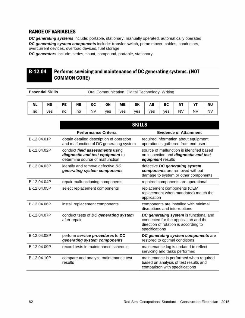
82 Red Seal Occupational Standard – Construction Electrician - 2015
RANGE OF VARIABLES DC generating systems include: portable, stationary, manually operated, automatically operated DC generating system components include: transfer switch, prime mover, cables, conductors, overcurrent devices, overload devices, fuel storage DC generators include: series, shunt, compound, portable, stationary
B-12.04 Performs servicing and maintenance of DC generating systems. (NOT COMMON CORE)
Essential Skills Oral Communication, Digital Technology, Writing
NL NS PE NB QC ON MB SK AB BC NT YT NU
no yes no no NV yes yes yes yes yes NV NV NV SKILLS
Performance Criteria Evidence of Attainment B-12.04.01P obtain detailed description of operation
and malfunction of DC generating system required information about equipment operation is gathered from end user
B-12.04.02P conduct field assessments using diagnostic and test equipment to determine source of malfunction
source of malfunction is identified based on inspection and diagnostic and test equipment results
B-12.04.03P identify and remove defective DC generating system components
defective DC generating system components are removed without damage to system or other components
B-12.04.04P repair malfunctioning components repaired components are operational B-12.04.05P select replacement components replacement components (OEM
replacement when mandated) match the application
B-12.04.06P install replacement components components are installed with minimal disruptions and interruptions
B-12.04.07P conduct tests of DC generating system after repair
DC generating system is functional and connected for the application and the direction of rotation is according to specifications
B-12.04.08P perform service procedures to DC generating system components
DC generating system components are restored to optimal conditions
B-12.04.09P record tests in maintenance schedule maintenance log is updated to reflect servicing and tasks performed
B-12.04.10P compare and analyze maintenance test results
maintenance is performed when required based on analysis of test results and comparison with specifications

83 Red Seal Occupational Standard – Construction Electrician - 2015
RANGE OF VARIABLES field assessments include: sensory inspections, technical inspections diagnostic and test equipment includes: multimeters, voltage testers, ammeters, oscilloscopes, high pot testers, thermographic imaging devices, phase rotation meters, insulation resistance testers, ground loop testers DC generating systems include: portable, stationary, manually operated, automatically operated DC generating system components include: transfer switch, brushes, prime mover, cables, conductors, overcurrent devices, overload devices, fuel storage service procedures include: cleaning cooling fans, adjusting belt tensioners, lubricating bearings and bushings, adjusting and setting brushes, cleaning switches KNOWLEDGE
Learning Outcomes Learning Objectives B-12.04.01L demonstrate knowledge of DC
generating systems, their applications and operation
identify types of DC generating systems and describe their characteristics
identify DC generating system components and describe their applications
interpret codes and regulations pertaining to DC generating systems
interpret information pertaining to DC generating systems found on drawings and specifications
explain the components and operating principles of DC generating systems
interpret information contained on DC generator nameplates
B-12.04.02L demonstrate knowledge of procedures used to service and maintain DC generating systems
describe the procedures used to service DC generating systems and DC generating system components
describe the procedures used to maintain DC generating systems and DC generating system components
RANGE OF VARIABLES DC generating systems include: portable, stationary, manually operated, automatically operated DC generating system components include: transfer switch, prime mover, cables, conductors, overcurrent devices, overload devices, fuel storage DC generators include: series, shunt, compound, portable, stationary

84 Red Seal Occupational Standard – Construction Electrician - 2015
Task B-13 Installs, services and maintains renewable energy systems. TASK DESCRIPTOR Alternative and renewable energy generation systems can be used to supplement power when power from the utility is unavailable or the building is isolated from the power grid. These systems can also feed energy back to the power grid. For the purpose of this standard, alternative systems are considered non-utility systems. Renewable systems are systems such as solar, wind or tidal powered that use renewable sources of energy. For the purpose of this standard, installation includes both new installations and upgrading of systems by removing and replacing components. Construction electricians service alternative and renewable energy systems by troubleshooting, diagnosing faults, and repairing them. They also perform maintenance to ensure alternative and renewable energy systems are in good operating condition. INDUSTRY EXPECTED PERFORMANCE The task must be performed according to the applicable jurisdictional codes and standards. All health and safety standards must be respected. Work should be done efficiently and at a high quality without material waste or harm to the environment. All requirements of the manufacturer, client specifications and the AHJ must be met. At a journeyperson level of performance, all tasks must be done with minimal direction and supervision. B-13.01 Installs renewable energy systems. Essential Skills Thinking Skills, Numeracy, Document Use
NL NS PE NB QC ON MB SK AB BC NT YT NU
yes yes yes yes NV yes yes yes yes yes NV NV NV SKILLS
Performance Criteria Evidence of Attainment B-13.01.01P determine energy requirements for the
application by performing load calculations and tests
calculations are performed according to applicable energy requirements or production requirements
B-13.01.02P determine capacity of renewable energy system to be installed for the application
size and capacity of renewable energy system are determined
B-13.01.03P determine the type of renewable energy connection to be installed for the application
renewable energy connection type is determined
B-13.01.04P position and mount renewable energy systems and control and storage system components
renewable energy systems and control and storage system components are securely mounted using fasteners designed for attachment to the material of the support structure

85 Red Seal Occupational Standard – Construction Electrician - 2015
B-13.01.05P terminate and interconnect renewable energy system and control system components
renewable energy system and control system components are terminated and interconnected according to electrical drawings and specifications, and job and CEC requirements (for example, conductors secure with no insulation compromised and not pinched)
B-13.01.06P conduct tests of renewable energy system after installation and record results
renewable energy system is functional and connected according to the application requirements
B-13-01.07P remove existing equipment when replacing and update documentation
equipment is removed with minimal impact to the environment and drawings reflect operational changes
B-13-01.08P determine ground and bonding requirements for renewable energy systems
method and materials for system grounding are selected
RANGE OF VARIABLES renewable energy systems include: fuel cells, wind turbines, photovoltaic modules, hydrokinetic, geothermal, hydraulic turbine, tidal renewable energy connections include: grid dependent and grid independent (stand-alone) control system components include: transfer switches, sun-tracking systems, batteries, charge controller, load bank, inverters with anti-islanding capability used components: pumped hydro, compressed air energy storage, batteries (various technologies), flow batteries, flywheel energy storage fasteners include: screws, straps, inserts, anchors, wedge clamps, seismic restraints, insulators KNOWLEDGE
Learning Outcomes Learning Objectives B-13.01.01L demonstrate knowledge of renewable
energy systems, their applications and operation
identify types of renewable energy systems and describe their characteristics, applications and operation
identify renewable energy system components and describe their characteristics, applications and operation
identify type of renewable energy connections
interpret codes and regulations pertaining to renewable energy systems
define terminology associated with renewable energy systems

86 Red Seal Occupational Standard – Construction Electrician - 2015
B-13.01.02L demonstrate knowledge of procedures to install and connect renewable energy systems and control system components
describe the procedures used to install renewable energy systems and control system components
describe the procedures used to connect renewable energy systems and control system components
RANGE OF VARIABLES renewable energy systems include: fuel cells, wind turbines, photovoltaic modules, hydrokinetic, geothermal, hydraulic turbine, tidal renewable energy connections include: grid dependent, grid independent (stand-alone) control system components include: transfer switches, sun-tracking systems, batteries, charge controller, load bank, inverters with anti-islanding capability
B-13.02 Performs servicing and maintenance of renewable energy systems. Essential Skills Oral Communication, Digital Technology, Writing
NL NS PE NB QC ON MB SK AB BC NT YT NU
yes yes yes yes NV yes yes yes yes yes NV NV NV SKILLS
Performance Criteria Evidence of Attainment B-13.02.01P obtain detailed description of operation
and malfunction of renewable energy systems
required information about equipment operation is gathered from end user
B-13.02.02P conduct field assessments using diagnostic and test equipment to determine source of malfunction
source of malfunction is identified based on inspection and diagnostic and test equipment results
B-13.02.03P identify and remove defective renewable energy systems components
defective components are removed without damage to system or other components
B-13.02.04P repair malfunctioning components repaired components are operational B-13.02.05P select replacement components replacement components (OEM
replacement when mandated) match the application
B-13.02.06P install replacement components components are installed with minimal disruptions and interruptions
B-13.02.07P conduct tests of renewable energy systems after repair
renewable energy system is connected according to job, AHJ and CEC requirements
B-13.02.08P lubricate, clean and adjust components renewable energy systems are restored to optimal conditions
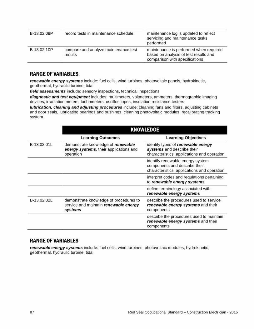
87 Red Seal Occupational Standard – Construction Electrician - 2015
B-13.02.09P record tests in maintenance schedule maintenance log is updated to reflect servicing and maintenance tasks performed
B-13.02.10P compare and analyze maintenance test results
maintenance is performed when required based on analysis of test results and comparison with specifications
RANGE OF VARIABLES renewable energy systems include: fuel cells, wind turbines, photovoltaic panels, hydrokinetic, geothermal, hydraulic turbine, tidal field assessments include: sensory inspections, technical inspections diagnostic and test equipment includes: multimeters, voltmeters, ammeters, thermographic imaging devices, irradiation meters, tachometers, oscilloscopes, insulation resistance testers lubrication, cleaning and adjusting procedures include: cleaning fans and filters, adjusting cabinets and door seals, lubricating bearings and bushings, cleaning photovoltaic modules, recalibrating tracking system KNOWLEDGE
Learning Outcomes Learning Objectives B-13.02.01L demonstrate knowledge of renewable
energy systems, their applications and operation
identify types of renewable energy systems and describe their characteristics, applications and operation
identify renewable energy system components and describe their characteristics, applications and operation
interpret codes and regulations pertaining to renewable energy systems
define terminology associated with renewable energy systems
B-13.02.02L demonstrate knowledge of procedures to service and maintain renewable energy systems
describe the procedures used to service renewable energy systems and their components
describe the procedures used to maintain renewable energy systems and their components
RANGE OF VARIABLES renewable energy systems include: fuel cells, wind turbines, photovoltaic modules, hydrokinetic, geothermal, hydraulic turbine, tidal

88 Red Seal Occupational Standard – Construction Electrician - 2015
Task B-14 Installs, services and maintains high voltage systems. TASK DESCRIPTOR Construction electricians assemble, install, erect and connect equipment and cables for high voltage applications (voltages above 750V) such as switchyards, sub-stations, electrical vaults, solar photovoltaic systems, chillers and MCC’s. They use specific equipment, tests and procedures to ensure the work is performed safely due to the inherent hazards regarding high voltage systems that can cause property damage, serious injury or death. For the purpose of this standard, installation includes both new installations and upgrading of systems by removing and replacing components. Construction electricians service high voltage systems by troubleshooting, diagnosing faults, and repairing them. They also perform maintenance to ensure these systems are in good operating condition. INDUSTRY EXPECTED PERFORMANCE The task must be performed according to the applicable jurisdictional codes and standards. All health and safety standards must be respected. Work should be done efficiently and at a high quality without material waste or harm to the environment. All requirements of the manufacturer, client specifications and the AHJ must be met. At a journeyperson level of performance, all tasks must be done with minimal direction and supervision. B-14.01 Installs high voltage equipment. Essential Skills Reading, Digital Technology, Document Use
NL NS PE NB QC ON MB SK AB BC NT YT NU
yes yes yes yes NV yes yes yes yes yes NV NV NV SKILLS
Performance Criteria Evidence of Attainment B-14.01.01P determine installation requirements for
high voltage equipment requirements for high voltage equipment is determined subject to location, AHJ and client requirements
B-14.01.02P lay out high voltage equipment layout allows for high voltage equipment to be installed level, square and plumb, matching building lines with required access and egress
B-14.01.03P assemble high voltage equipment high voltage equipment is assembled according to job requirements and manufacturers’ specifications
B-14.01.04P interconnect high voltage equipment high voltage equipment is interconnected using busbars or cabling systems depending on application
B-14.01.05P bond non-current carrying metallic components
non-current carrying metallic components are bonded to ground

89 Red Seal Occupational Standard – Construction Electrician - 2015
B-14.01.06P install ground grid ground grid is installed according to step and touch voltage requirements and CEC requirements
B-14.01.07P perform ground resistance test ground resistance test is performed using testing equipment and recorded
B-14.01.08P perform acceptance tests acceptance tests are conducted using required testing standards
B-14.01.09P install labelling and signage on high voltage equipment
high voltage equipment is labelled, and signage is evident according to client, site and CEC requirements
B-14.01.10P update required documentation changes to the installation of high voltage equipment are recorded on documentation required by AHJ
B-14.01.11P remove and dispose of existing high voltage equipment and components when replacing and update documentation
used high voltage equipment and components are disposed of according to local codes and waste disposal requirements
RANGE OF VARIABLES high voltage equipment includes: distribution equipment, contactors, motor starters, transformers, MCC, capacitors, reactors, switches, disconnects, rectifiers, reclosers, PTs, CTs non-current carrying metallic components include: fences, towers, doors, enclosures testing equipment includes: ground loop impedance tester, megohmmeter acceptance tests include: polarization, ground grid resistance, high pot, phasing, functionality, timing, current injection testing standards include: manufacturer, Institute of Electrical and Electronics Engineers (IEEE), North American Electrical Testing Association (NETA), AHJ documentation required by AHJ include: as-builts, schematics (AC, DC), drive drawings, shop drawings, single-line drawings, three-line drawings KNOWLEDGE
Learning Outcomes Learning Objectives B-14.01.01L demonstrate knowledge of high voltage
equipment interpret codes and regulations pertaining to high voltage equipment
interpret information pertaining to high voltage equipment found on drawings and specifications
identify grounding conductors, equipment and components, and describe their characteristics and applications
identify bonding conductors, equipment and components, and describe their characteristics and applications
explain the purpose of grounding grids in relation to step and touch voltages
explain the function of high voltage equipment
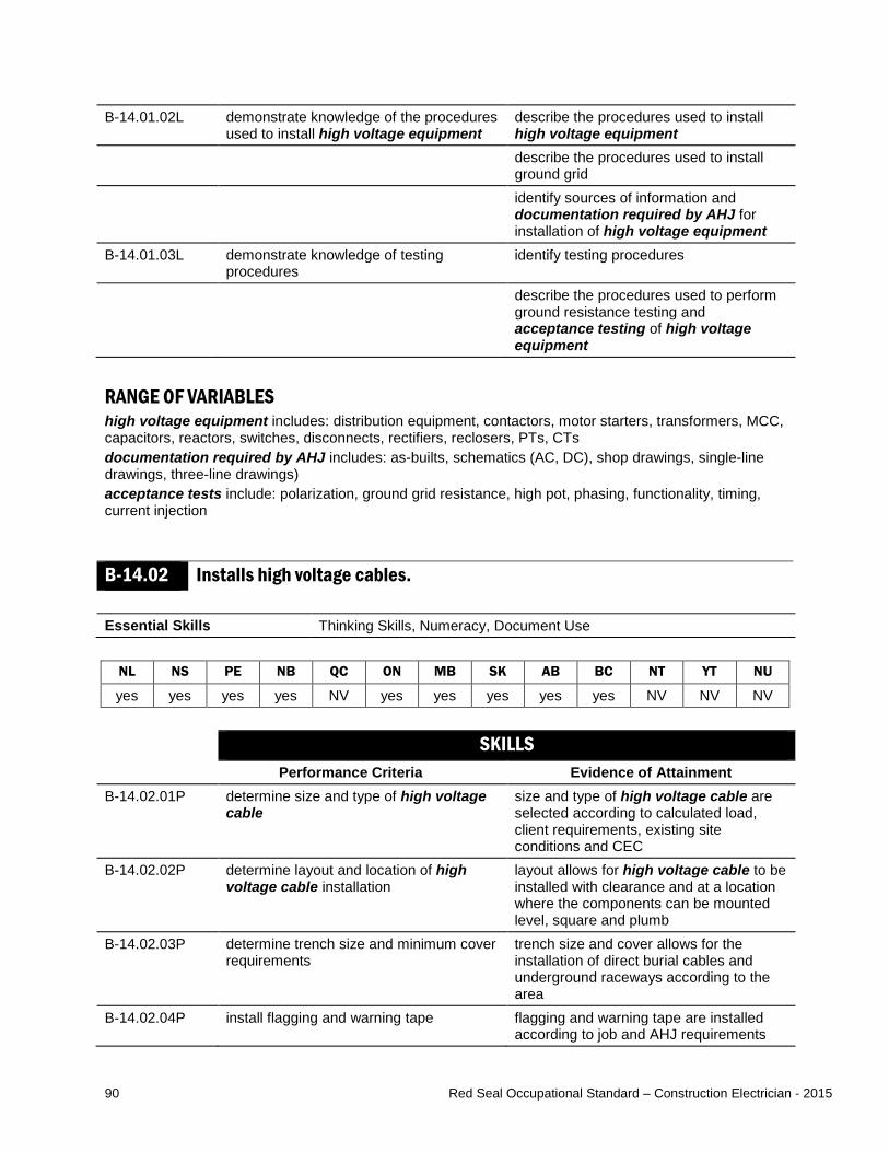
90 Red Seal Occupational Standard – Construction Electrician - 2015
B-14.01.02L demonstrate knowledge of the procedures used to install high voltage equipment
describe the procedures used to install high voltage equipment
describe the procedures used to install ground grid
identify sources of information and documentation required by AHJ for installation of high voltage equipment
B-14.01.03L demonstrate knowledge of testing procedures
identify testing procedures
describe the procedures used to perform ground resistance testing and acceptance testing of high voltage equipment
RANGE OF VARIABLES high voltage equipment includes: distribution equipment, contactors, motor starters, transformers, MCC, capacitors, reactors, switches, disconnects, rectifiers, reclosers, PTs, CTs documentation required by AHJ includes: as-builts, schematics (AC, DC), shop drawings, single-line drawings, three-line drawings) acceptance tests include: polarization, ground grid resistance, high pot, phasing, functionality, timing, current injection
B-14.02 Installs high voltage cables. Essential Skills Thinking Skills, Numeracy, Document Use
NL NS PE NB QC ON MB SK AB BC NT YT NU
yes yes yes yes NV yes yes yes yes yes NV NV NV SKILLS
Performance Criteria Evidence of Attainment B-14.02.01P determine size and type of high voltage
cable size and type of high voltage cable are selected according to calculated load, client requirements, existing site conditions and CEC
B-14.02.02P determine layout and location of high voltage cable installation
layout allows for high voltage cable to be installed with clearance and at a location where the components can be mounted level, square and plumb
B-14.02.03P determine trench size and minimum cover requirements
trench size and cover allows for the installation of direct burial cables and underground raceways according to the area
B-14.02.04P install flagging and warning tape flagging and warning tape are installed according to job and AHJ requirements
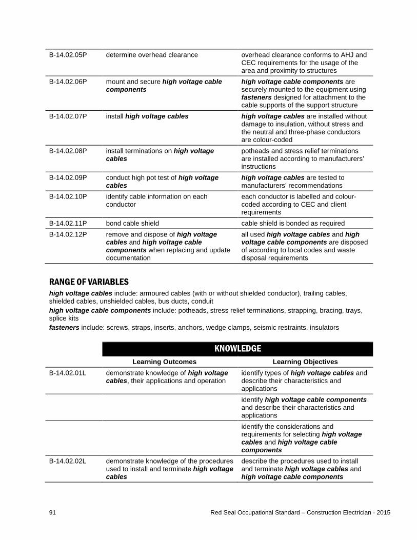
91 Red Seal Occupational Standard – Construction Electrician - 2015
B-14.02.05P determine overhead clearance overhead clearance conforms to AHJ and CEC requirements for the usage of the area and proximity to structures
B-14.02.06P mount and secure high voltage cable components
high voltage cable components are securely mounted to the equipment using fasteners designed for attachment to the cable supports of the support structure
B-14.02.07P install high voltage cables high voltage cables are installed without damage to insulation, without stress and the neutral and three-phase conductors are colour-coded
B-14.02.08P install terminations on high voltage cables
potheads and stress relief terminations are installed according to manufacturers’ instructions
B-14.02.09P conduct high pot test of high voltage cables
high voltage cables are tested to manufacturers’ recommendations
B-14.02.10P identify cable information on each conductor
each conductor is labelled and colour-coded according to CEC and client requirements
B-14.02.11P bond cable shield cable shield is bonded as required B-14.02.12P remove and dispose of high voltage
cables and high voltage cable components when replacing and update documentation
all used high voltage cables and high voltage cable components are disposed of according to local codes and waste disposal requirements
RANGE OF VARIABLES high voltage cables include: armoured cables (with or without shielded conductor), trailing cables, shielded cables, unshielded cables, bus ducts, conduit high voltage cable components include: potheads, stress relief terminations, strapping, bracing, trays, splice kits fasteners include: screws, straps, inserts, anchors, wedge clamps, seismic restraints, insulators KNOWLEDGE
Learning Outcomes Learning Objectives B-14.02.01L demonstrate knowledge of high voltage
cables, their applications and operation identify types of high voltage cables and describe their characteristics and applications
identify high voltage cable components and describe their characteristics and applications
identify the considerations and requirements for selecting high voltage cables and high voltage cable components
B-14.02.02L demonstrate knowledge of the procedures used to install and terminate high voltage cables
describe the procedures used to install and terminate high voltage cables and high voltage cable components
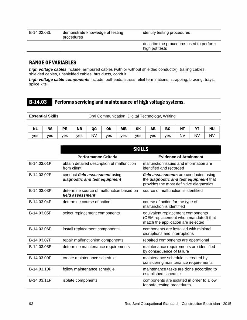
92 Red Seal Occupational Standard – Construction Electrician - 2015
B-14.02.03L demonstrate knowledge of testing procedures
identify testing procedures
describe the procedures used to perform high pot tests
RANGE OF VARIABLES high voltage cables include: armoured cables (with or without shielded conductor), trailing cables, shielded cables, unshielded cables, bus ducts, conduit high voltage cable components include: potheads, stress relief terminations, strapping, bracing, trays, splice kits
B-14.03 Performs servicing and maintenance of high voltage systems. Essential Skills Oral Communication, Digital Technology, Writing
NL NS PE NB QC ON MB SK AB BC NT YT NU
yes yes yes yes NV yes yes yes yes yes NV NV NV SKILLS
Performance Criteria Evidence of Attainment B-14.03.01P obtain detailed description of malfunction
from client malfunction issues and information are identified and recorded
B-14.03.02P conduct field assessment using diagnostic and test equipment
field assessments are conducted using the diagnostic and test equipment that provides the most definitive diagnostics
B-14.03.03P determine source of malfunction based on field assessment
source of malfunction is identified
B-14.03.04P determine course of action course of action for the type of malfunction is identified
B-14.03.05P select replacement components equivalent replacement components (OEM replacement when mandated) that match the application are selected
B-14.03.06P install replacement components components are installed with minimal disruptions and interruptions
B-14.03.07P repair malfunctioning components repaired components are operational B-14.03.08P determine maintenance requirements maintenance requirements are identified
by consequence of failure B-14.03.09P create maintenance schedule maintenance schedule is created by
considering maintenance requirements B-14.03.10P follow maintenance schedule maintenance tasks are done according to
established schedule B-14.03.11P isolate components components are isolated in order to allow
for safe testing procedures

93 Red Seal Occupational Standard – Construction Electrician - 2015
B-14.03.12P conduct tests using diagnostic and test equipment
tests are conducted according to established maintenance schedule and test results are recorded
B-14.03.13P update maintenance log and required documentation
maintenance log and required documentation is updated to reflect servicing and maintenance tasks performed
RANGE OF VARIABLES field assessments include: sensory inspections, technical inspections diagnostic and test equipment includes: multimeters, voltage testers, ammeters, power quality analyzers, high pot testers, thermographic imaging devices, phase rotation meters, insulation resistance testers, ground loop tester, arc flash equipment, ground straps required documentation includes: schematic diagrams and drawings, maintenance schedules, single line diagrams KNOWLEDGE
Learning Outcomes Learning Objectives B-14.03.01L demonstrate knowledge of the procedures
used to service and maintain high voltage equipment
describe the procedures used to service high voltage equipment and their components
describe the procedures used to maintain high voltage equipment and their components
B-14.03.02L demonstrate knowledge of the methods used to service and maintain high voltage cables
describe the procedures used to service, high voltage cables and their components
describe the procedures used to maintain high voltage cables and their components
RANGE OF VARIABLES high voltage equipment includes: distribution equipment, contactors, motor starters, transformers, MCC, capacitors, reactors, switches, disconnects, rectifiers, reclosers, PTs, CTs high voltage cable components include: potheads, stress relief terminations, strapping, bracing, trays, splice kits high voltage cables include: armoured cables (with or without shielded conductor), trailing cables, shielded cables, bus ducts, conduit

94 Red Seal Occupational Standard – Construction Electrician - 2015
Task B-15 Installs, services and maintains transformers. TASK DESCRIPTOR Construction electricians install extra-low, low and high voltage transformers to condition or alter voltage and current. Common transformer uses include signal control, isolation, distribution and transmission. For the purpose of this standard, installation includes both new installations and upgrading of systems by removing and replacing components. Construction electricians service transformers by troubleshooting, diagnosing faults, and repairing them. They also perform maintenance to ensure transformers are in good operating condition. INDUSTRY EXPECTED PERFORMANCE The task must be performed according to the applicable jurisdictional codes and standards. All health and safety standards must be respected. Work should be done efficiently and at a high quality without material waste or harm to the environment. All requirements of the manufacturer, client specifications and the AHJ must be met. At a journeyperson level of performance, all tasks must be done with minimal direction and supervision. B-15.01 Installs extra-low voltage transformers. Essential Skills Thinking Skills, Numeracy, Document Use
NL NS PE NB QC ON MB SK AB BC NT YT NU
yes yes yes yes NV yes yes yes yes yes NV NV NV SKILLS
Performance Criteria Evidence of Attainment B-15.01.01P determine type of extra-low voltage
transformer required and its VA rating type of extra-low voltage transformer meets criteria for operation
B-15.01.02P calculate conductor requirements conductor type and size are selected according to CEC requirements
B-15.01.03P determine overcurrent devices based on requirements
type and rating of overcurrent devices are determined
B-15.01.04P install overcurrent devices based on requirements
overcurrent devices are installed such that transformer is protected
B-15.01.05P position and mount extra-low voltage transformer
extra-low voltage transformer is mounted according to the application
B-15.01.06P connect transformer leads transformer leads are connected according to the application

95 Red Seal Occupational Standard – Construction Electrician - 2015
B-15.01.07P conduct tests of extra-low voltage transformer after installation and record results
extra-low voltage transformer is functional and connected according to the application requirements
B-15.01.08P remove existing extra-low voltage transformer when replacing and update documentation
extra-low voltage transformers are removed with minimal impact to the environment and drawings reflect operational changes
RANGE OF VARIABLES extra-low voltage transformers include: Class 1 and Class 2 circuits according to the CEC KNOWLEDGE
Learning Outcomes Learning Objectives B-15.01.01L demonstrate knowledge of extra-low
voltage transformers, their applications and operation
explain the operating principles of extra-low voltage transformers
interpret information contained on extra-low voltage transformer nameplates
identify types of extra-low voltage transformers and describe their characteristics and applications
identify extra-low voltage transformer components and describe their characteristics and applications
identify the considerations and requirements for selecting extra-low voltage transformers
B-15.01.02L demonstrate knowledge of procedures used to install extra-low voltage transformers
describe the procedures used to install extra-low voltage transformers
RANGE OF VARIABLES extra-low voltage transformers include: Class 1 and Class 2 circuits according to the CEC extra-low voltage transformer components include: casing, core, primary and secondary windings

96 Red Seal Occupational Standard – Construction Electrician - 2015
B-15.02 Installs low-voltage single-phase transformers. Essential Skills Numeracy, Digital Technology, Document Use
NL NS PE NB QC ON MB SK AB BC NT YT NU
yes yes yes yes NV yes yes yes yes yes NV NV NV SKILLS
Performance Criteria Evidence of Attainment B-15.02.01P determine type of low-voltage single-
phase transformer required and its kilovolt-amp (kVA) rating
type of low-voltage single-phase transformer meets criteria for operation
B-15.02.02P calculate conductor requirements conductor type and size are selected according to CEC requirements
B-15.02.03P determine overcurrent devices based on system requirements
type and rating of overcurrent devices are determined according to CEC requirements
B-15.02.04P install overcurrent devices based on system requirements
overcurrent devices are installed such that transformer is protected
B-15.02.05P position and mount low-voltage single-phase transformer
low-voltage single-phase transformer is mounted according to the application
B-15.02.06P connect transformer leads transformer leads are connected according to the application
B-15.02.07P select and change tap settings of low-voltage single-phase transformers
output voltage meets application requirements
B-15.02.08P ground and bond transformer transformer is grounded and bonded to meet CEC requirements
B-15.02.09P conduct tests of low-voltage single-phase transformer after installation and record results
low-voltage single-phase transformer is functional and connected according to the application
B-15.02.10P remove existing low-voltage single-phase transformer when replacing and update documentation
low-voltage single-phase transformer is removed with minimal impact to the environment and drawings reflect operational changes
RANGE OF VARIABLES low-voltage single-phase transformers include: dry-type and liquid-filled system requirements include: input/output voltage, polarities, kVA ratings, conductor size, overcurrent protection tests include: insulation test, voltage test, polarity test, amperage test

97 Red Seal Occupational Standard – Construction Electrician - 2015
KNOWLEDGE Learning Outcomes Learning Objectives
B-15.02.01L demonstrate knowledge of low-voltage single-phase transformers, their applications and operation
explain the operating principles of low-voltage single-phase transformers
identify types of low-voltage single-phase transformers and describe their characteristics and applications
identify low-voltage single-phase transformer components and describe their characteristics and applications
interpret information contained on low-voltage single-phase transformer nameplates
explain transformer polarity and terminal markings
identify the considerations and requirements for selecting low-voltage single-phase transformers
B-15.02.02L demonstrate knowledge of procedures used to install low-voltage single-phase transformers
describe the procedures used to install low-voltage single-phase transformers
interpret codes and regulations pertaining to low-voltage single-phase transformers
describe the procedures used to install low-voltage single-phase transformers in parallel
RANGE OF VARIABLES low-voltage single-phase transformers include: dry-type and liquid-filled low-voltage single-phase transformer components include: oil pumps, ventilation fans, casing, core, primary and secondary windings, bushings, on-line and off-line tap changers, oil
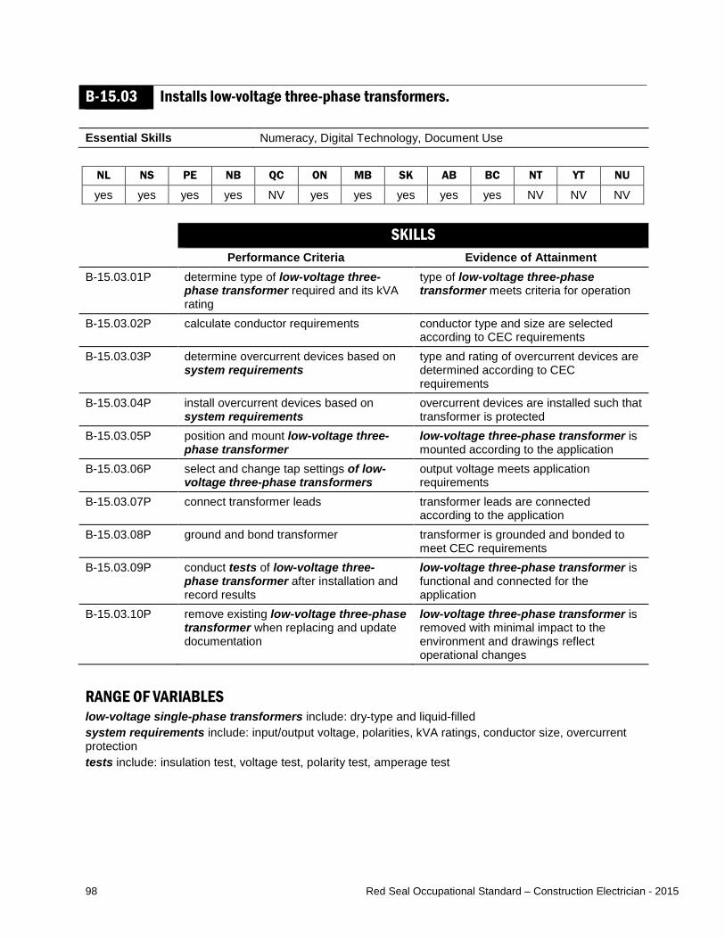
98 Red Seal Occupational Standard – Construction Electrician - 2015
B-15.03 Installs low-voltage three-phase transformers. Essential Skills Numeracy, Digital Technology, Document Use
NL NS PE NB QC ON MB SK AB BC NT YT NU
yes yes yes yes NV yes yes yes yes yes NV NV NV SKILLS
Performance Criteria Evidence of Attainment B-15.03.01P determine type of low-voltage three-
phase transformer required and its kVA rating
type of low-voltage three-phase transformer meets criteria for operation
B-15.03.02P calculate conductor requirements conductor type and size are selected according to CEC requirements
B-15.03.03P determine overcurrent devices based on system requirements
type and rating of overcurrent devices are determined according to CEC requirements
B-15.03.04P install overcurrent devices based on system requirements
overcurrent devices are installed such that transformer is protected
B-15.03.05P position and mount low-voltage three-phase transformer
low-voltage three-phase transformer is mounted according to the application
B-15.03.06P select and change tap settings of low-voltage three-phase transformers
output voltage meets application requirements
B-15.03.07P connect transformer leads transformer leads are connected according to the application
B-15.03.08P ground and bond transformer transformer is grounded and bonded to meet CEC requirements
B-15.03.09P conduct tests of low-voltage three-phase transformer after installation and record results
low-voltage three-phase transformer is functional and connected for the application
B-15.03.10P remove existing low-voltage three-phase transformer when replacing and update documentation
low-voltage three-phase transformer is removed with minimal impact to the environment and drawings reflect operational changes
RANGE OF VARIABLES low-voltage single-phase transformers include: dry-type and liquid-filled system requirements include: input/output voltage, polarities, kVA ratings, conductor size, overcurrent protection tests include: insulation test, voltage test, polarity test, amperage test

99 Red Seal Occupational Standard – Construction Electrician - 2015
KNOWLEDGE Learning Outcomes Learning Objectives
B-15.03.01L demonstrate knowledge of low-voltage three-phase transformers, their applications and operation
explain the operating principles of low-voltage three-phase transformers
identify types of low-voltage three-phase transformers and describe their characteristics and applications
identify winding configurations for low-voltage three-phase transformers
identify low-voltage three-phase transformer components and describe their characteristics and applications
interpret information contained on low-voltage three-phase transformer nameplates
explain transformer polarity and terminal markings
identify the considerations and requirements for selecting low-voltage three-phase transformers
B-15.03.02L demonstrate knowledge of procedures used to install low-voltage three-phase transformers
describe the procedures used to install low-voltage three-phase transformers
interpret codes and regulations pertaining to low-voltage three-phase transformers
describe the procedures used to install low-voltage three-phase transformers in parallel
RANGE OF VARIABLES low-voltage three-phase transformers include: dry-type and liquid-filled winding configurations include: wye-wye, open-wye, wye-delta, delta-wye, open-delta, delta-delta, zig-zag low-voltage three-phase transformer components include: oil pumps, ventilation fans, casing, core, primary and secondary windings, bushings, on-line and off-line tap changers, oil

100 Red Seal Occupational Standard – Construction Electrician - 2015
B-15.04 Installs high voltage transformers. Essential Skills Oral Communication, Digital Technology, Writing
NL NS PE NB QC ON MB SK AB BC NT YT NU
yes yes yes yes NV yes yes yes yes yes NV NV NV SKILLS
Performance Criteria Evidence of Attainment B-15.04.01P determine type of high voltage
transformer required and its kVA rating type of high voltage transformer meets criteria for operation
B-15.04.02P calculate conductor requirements conductor type and size are calculated according to CEC requirements
B-15.04.03P determine overcurrent devices based on system requirements
type and rating of overcurrent devices are determined
B-15.04.04P install overcurrent devices based on system requirements
overcurrent devices are installed such that transformer is protected
B-15.04.05P position and mount high voltage transformer
high voltage transformer is mounted according to the application
B-15.04.06P select and change tap settings of high voltage transformers
output voltage meets application requirements
B-15.04.07P connect transformer leads transformer leads are connected according to the application
B-15.04.08P ground and bond transformer transformer is bonded and grounded to meet CEC requirements
B-15.04.09P conduct tests of high voltage transformer after installation and record results
high voltage transformer is functional and connected for the application
B-15.04.10P remove existing high voltage transformer when replacing and update documentation
high voltage transformer is removed with minimal impact to the environment and drawings reflect operational changes
RANGE OF VARIABLES high voltage transformers include: dry-type and liquid-filled system requirements include: input/output voltage, polarities, kVA ratings, conductor size, overcurrent protection tests include: insulation test, voltage test, high-pot test, oil analysis test, amperage test

101 Red Seal Occupational Standard – Construction Electrician - 2015
KNOWLEDGE Learning Outcomes Learning Objectives
B-15.04.01L demonstrate knowledge of high voltage transformers, their applications and operation
explain the operating principles of high voltage transformers
identify types of high voltage transformers and describe their characteristics and applications
identify winding configurations for high voltage transformers
identify high voltage transformer components and describe their characteristics and applications
interpret information contained on high voltage transformer nameplates
explain transformer polarity and terminal markings
identify the considerations and requirements for selecting high voltage transformers
B-15.04.02L demonstrate knowledge of procedures used to install high voltage transformers
describe the procedures used to install high voltage transformers
interpret codes and regulations pertaining to high voltage transformers
describe the procedures used to install high voltage transformers in parallel
RANGE OF VARIABLES high voltage transformers include: dry-type and liquid-filled winding configurations include: wye-wye, open-wye, wye-delta, delta-wye, open-delta, delta-delta, zig-zag high voltage transformer components include: oil pumps, ventilation fans, casing, core, primary and secondary windings, desiccant breather, buchholz relay, bushings, on-line and off-line tap changers, oil
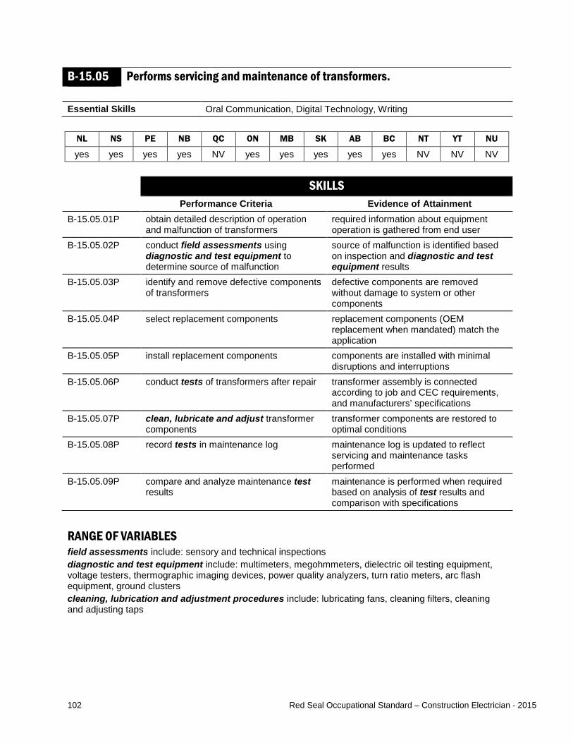
102 Red Seal Occupational Standard – Construction Electrician - 2015
B-15.05 Performs servicing and maintenance of transformers. Essential Skills Oral Communication, Digital Technology, Writing
NL NS PE NB QC ON MB SK AB BC NT YT NU
yes yes yes yes NV yes yes yes yes yes NV NV NV SKILLS
Performance Criteria Evidence of Attainment B-15.05.01P obtain detailed description of operation
and malfunction of transformers required information about equipment operation is gathered from end user
B-15.05.02P conduct field assessments using diagnostic and test equipment to determine source of malfunction
source of malfunction is identified based on inspection and diagnostic and test equipment results
B-15.05.03P identify and remove defective components of transformers
defective components are removed without damage to system or other components
B-15.05.04P select replacement components replacement components (OEM replacement when mandated) match the application
B-15.05.05P install replacement components components are installed with minimal disruptions and interruptions
B-15.05.06P conduct tests of transformers after repair transformer assembly is connected according to job and CEC requirements, and manufacturers’ specifications
B-15.05.07P clean, lubricate and adjust transformer components
transformer components are restored to optimal conditions
B-15.05.08P record tests in maintenance log maintenance log is updated to reflect servicing and maintenance tasks performed
B-15.05.09P compare and analyze maintenance test results
maintenance is performed when required based on analysis of test results and comparison with specifications
RANGE OF VARIABLES field assessments include: sensory and technical inspections diagnostic and test equipment include: multimeters, megohmmeters, dielectric oil testing equipment, voltage testers, thermographic imaging devices, power quality analyzers, turn ratio meters, arc flash equipment, ground clusters cleaning, lubrication and adjustment procedures include: lubricating fans, cleaning filters, cleaning and adjusting taps

103 Red Seal Occupational Standard – Construction Electrician - 2015
KNOWLEDGE Learning Outcomes Learning Objectives
B-15.05.01L demonstrate knowledge of transformers, their applications and procedures for use
identify types of transformers and describe their characteristics and applications
identify transformer components and describe their characteristics
interpret codes and regulations pertaining to transformers
interpret information pertaining to transformers found on drawings and specifications
explain the construction and operating principles of transformers
interpret information contained on transformer nameplates
B-15.05.02L demonstrate knowledge of procedures used to service and maintain transformers
describe the procedures used to service transformers and their components
describe the procedures used to maintain transformers and their components
RANGE OF VARIABLES transformers include: extra-low voltage, dry-type and liquid-filled transformer components include: oil pumps, ventilation fans, casing, core, primary and secondary windings, desiccant breather, buchholz relay, bushings, on-line and off-line tap changers, oil

104 Red Seal Occupational Standard – Construction Electrician - 2015
MAJOR WORK ACTIVITY C INSTALLS, SERVICES AND MAINTAINS WIRING SYSTEMS Task C-16 Installs, services and maintains raceways, cables and enclosures. TASK DESCRIPTOR Raceways support and protect conductors. Enclosures may be used to access and terminate the content of the raceway, and to facilitate the pulling and the interconnection of components. Raceways and cables are installed in various environments. Construction electricians install, service and maintain raceways and conductors and restore openings in firewalls. For the purpose of this standard, installation includes both new installations and upgrading of systems by removing and replacing components. Construction electricians service raceways, cables and enclosures by performing visual inspections, troubleshooting, diagnosing faults, and repairing them. They also perform maintenance to ensure raceways, cables and enclosures are in good operating condition. INDUSTRY EXPECTED PERFORMANCE The task must be performed according to the applicable jurisdictional codes and standards. All health and safety standards must be respected. Work should be done efficiently and at a high quality without material waste or harm to the environment. All requirements of the manufacturer, client specifications and the AHJ must be met. At a journeyperson level of performance, all tasks must be done with minimal direction and supervision.

105 Red Seal Occupational Standard – Construction Electrician - 2015
C-16.01 Installs conductors and cables. Essential Skills Thinking Skills, Numeracy, Document Use
NL NS PE NB QC ON MB SK AB BC NT YT NU
yes yes yes yes NV yes yes yes yes yes NV NV NV SKILLS
Performance Criteria Evidence of Attainment C-16.01.01P determine installation requirements and
select conductors and cables, and components
size and type of conductors, cables and components are selected according to drawings and specifications and CEC requirements
C-16.01.02P measure, cut and assemble conductors and cables, and components
conductors and cables are grouped, tagged and colour-coded according to drawings and specifications and client requirements
C-16.01.03P mount, support and install conductors and cables, and components
conductor and cable components are mounted, supported and installed according to drawings and specifications, CEC, National Building Code (NBC), and client requirements
C-16.01.04P prepare conductors and cables for termination
conductors and cables are cleaned and prepared for termination according to manufacturers’ specifications
C-16.01.05P terminate conductors and cables conductors and cables are terminated leaving no excessive bare conductor or loose strands, and phased and torqued according to electrical, client and manufacturers’ specifications
C-16.01.06P complete required documentation to reflect changes to the new and/or updated installation
all changes are recorded in the documentation and made available to the necessary parties
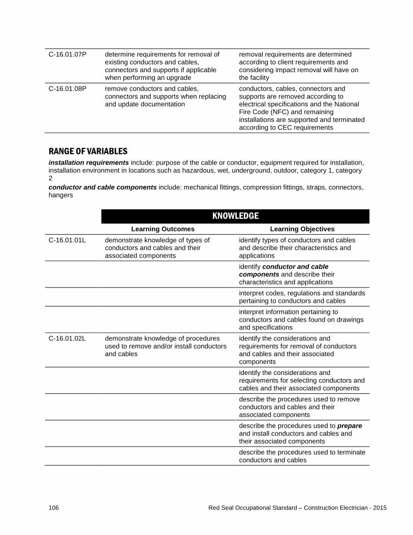
106 Red Seal Occupational Standard – Construction Electrician - 2015
C-16.01.07P determine requirements for removal of existing conductors and cables, connectors and supports if applicable when performing an upgrade
removal requirements are determined according to client requirements and considering impact removal will have on the facility
C-16.01.08P remove conductors and cables, connectors and supports when replacing and update documentation
conductors, cables, connectors and supports are removed according to electrical specifications and the National Fire Code (NFC) and remaining installations are supported and terminated according to CEC requirements
RANGE OF VARIABLES installation requirements include: purpose of the cable or conductor, equipment required for installation, installation environment in locations such as hazardous, wet, underground, outdoor, category 1, category 2 conductor and cable components include: mechanical fittings, compression fittings, straps, connectors, hangers KNOWLEDGE
Learning Outcomes Learning Objectives C-16.01.01L demonstrate knowledge of types of
conductors and cables and their associated components
identify types of conductors and cables and describe their characteristics and applications
identify conductor and cable components and describe their characteristics and applications
interpret codes, regulations and standards pertaining to conductors and cables
interpret information pertaining to conductors and cables found on drawings and specifications
C-16.01.02L demonstrate knowledge of procedures used to remove and/or install conductors and cables
identify the considerations and requirements for removal of conductors and cables and their associated components
identify the considerations and requirements for selecting conductors and cables and their associated components
describe the procedures used to remove conductors and cables and their associated components
describe the procedures used to prepare and install conductors and cables and their associated components
describe the procedures used to terminate conductors and cables
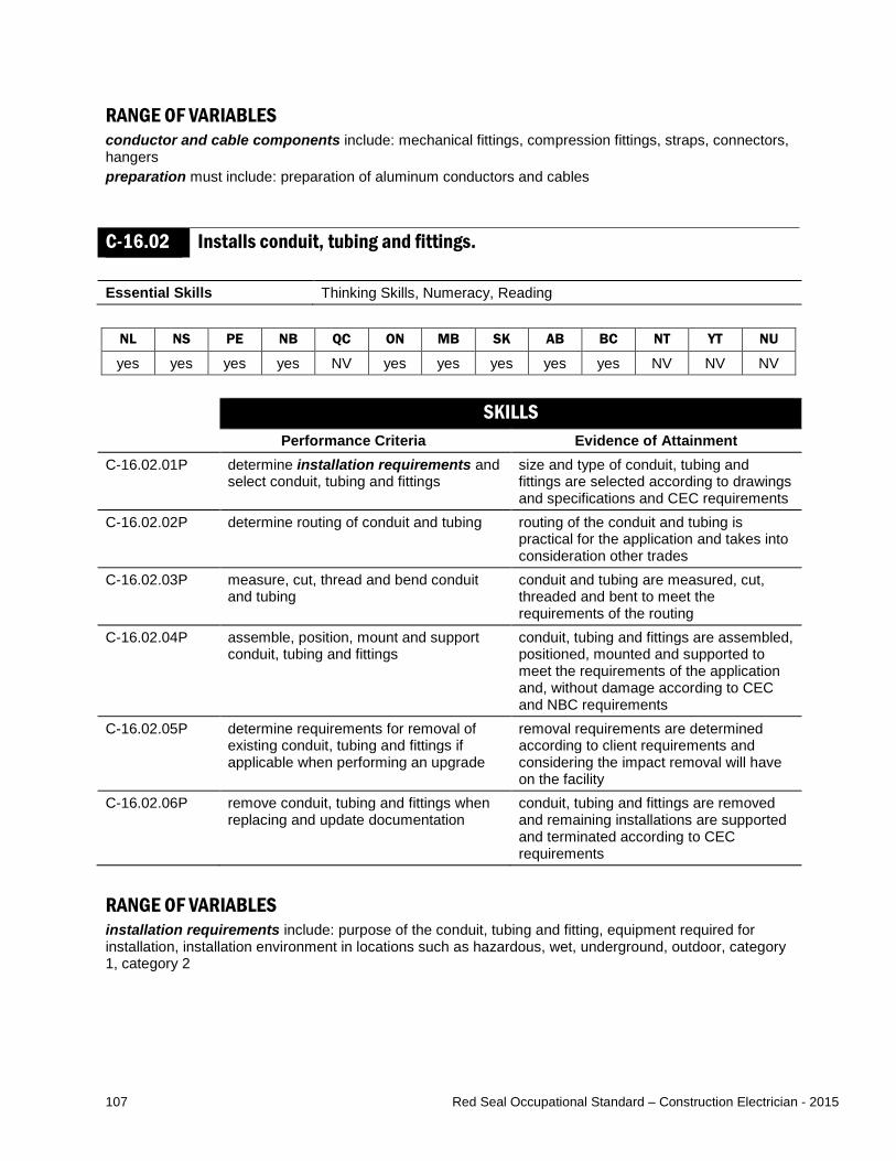
107 Red Seal Occupational Standard – Construction Electrician - 2015
RANGE OF VARIABLES conductor and cable components include: mechanical fittings, compression fittings, straps, connectors, hangers preparation must include: preparation of aluminum conductors and cables
C-16.02 Installs conduit, tubing and fittings. Essential Skills Thinking Skills, Numeracy, Reading
NL NS PE NB QC ON MB SK AB BC NT YT NU
yes yes yes yes NV yes yes yes yes yes NV NV NV SKILLS
Performance Criteria Evidence of Attainment C-16.02.01P determine installation requirements and
select conduit, tubing and fittings size and type of conduit, tubing and fittings are selected according to drawings and specifications and CEC requirements
C-16.02.02P determine routing of conduit and tubing routing of the conduit and tubing is practical for the application and takes into consideration other trades
C-16.02.03P measure, cut, thread and bend conduit and tubing
conduit and tubing are measured, cut, threaded and bent to meet the requirements of the routing
C-16.02.04P assemble, position, mount and support conduit, tubing and fittings
conduit, tubing and fittings are assembled, positioned, mounted and supported to meet the requirements of the application and, without damage according to CEC and NBC requirements
C-16.02.05P determine requirements for removal of existing conduit, tubing and fittings if applicable when performing an upgrade
removal requirements are determined according to client requirements and considering the impact removal will have on the facility
C-16.02.06P remove conduit, tubing and fittings when replacing and update documentation
conduit, tubing and fittings are removed and remaining installations are supported and terminated according to CEC requirements
RANGE OF VARIABLES installation requirements include: purpose of the conduit, tubing and fitting, equipment required for installation, installation environment in locations such as hazardous, wet, underground, outdoor, category 1, category 2
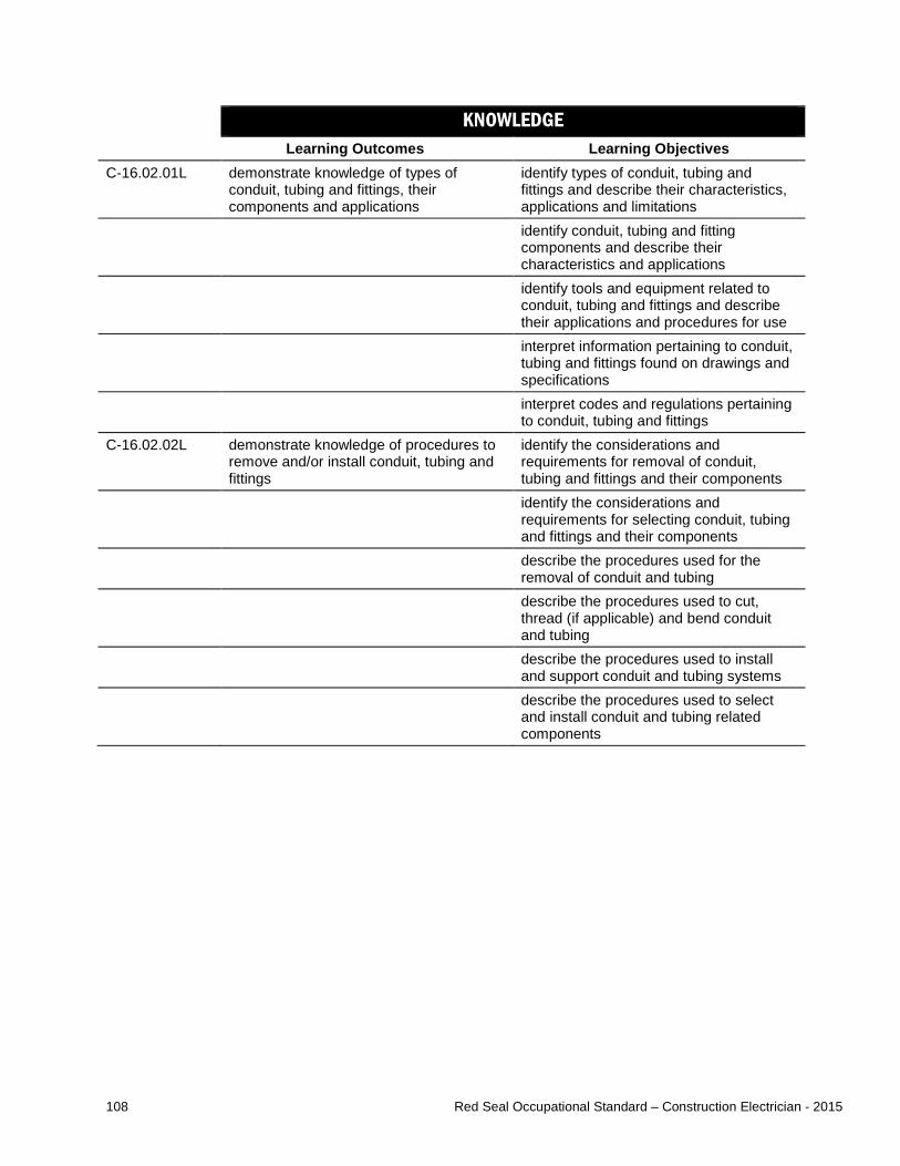
108 Red Seal Occupational Standard – Construction Electrician - 2015
KNOWLEDGE Learning Outcomes Learning Objectives
C-16.02.01L demonstrate knowledge of types of conduit, tubing and fittings, their components and applications
identify types of conduit, tubing and fittings and describe their characteristics, applications and limitations
identify conduit, tubing and fitting components and describe their characteristics and applications
identify tools and equipment related to conduit, tubing and fittings and describe their applications and procedures for use
interpret information pertaining to conduit, tubing and fittings found on drawings and specifications
interpret codes and regulations pertaining to conduit, tubing and fittings
C-16.02.02L demonstrate knowledge of procedures to remove and/or install conduit, tubing and fittings
identify the considerations and requirements for removal of conduit, tubing and fittings and their components
identify the considerations and requirements for selecting conduit, tubing and fittings and their components
describe the procedures used for the removal of conduit and tubing
describe the procedures used to cut, thread (if applicable) and bend conduit and tubing
describe the procedures used to install and support conduit and tubing systems
describe the procedures used to select and install conduit and tubing related components

109 Red Seal Occupational Standard – Construction Electrician - 2015
C-16.03 Installs raceways. Essential Skills Thinking Skills, Numeracy, Reading
NL NS PE NB QC ON MB SK AB BC NT YT NU
yes yes yes yes NV yes yes yes yes yes NV NV NV SKILLS
Performance Criteria Evidence of Attainment C-16.03.01P determine installation requirements and
select raceways size and type of raceway are selected according to drawings and specifications and CEC requirements
C-16.03.02P determine routing of raceway routing of the raceway is practical for the application and takes into consideration other trades
C-16.03.03P measure, cut and form raceways raceways are measured, cut and formed to meet the requirements of the routing
C-16.03.04P assemble, position, mount and support raceways
raceways are assembled, positioned, mounted and supported to meet the requirements of the application and without damage according to CEC and NBC requirements
C-16.03.05P determine requirements for removal of existing raceways if applicable when performing an upgrade
removal requirements are determined according to client requirements and considering the impact removal will have on the facility
C-16.03.06P remove raceways and their components when replacing and update documentation
raceways and their components are removed according to electrical specifications and remaining installations are supported and terminated according to CEC requirements
RANGE OF VARIABLES installation requirements include: purpose of the raceway, equipment required for installation, installation environment in locations such as hazardous, wet, underground, outdoor, category 1, category 2 raceways, in this sub-task include: cable tray wireways, underfloor raceways, busways, cellular raceways, surface raceways raceways in this sub-task, do not include conduit and tubing as these are covered in sub-task 16.02 raceway components include: fittings (couplings and connectors), supports

110 Red Seal Occupational Standard – Construction Electrician - 2015
KNOWLEDGE Learning Outcomes Learning Objectives
C-16.03.01L demonstrate knowledge of types of raceways and their components
identify types of raceways, and describe their characteristics and applications
identify raceway components and describe their characteristics and applications
interpret codes, regulations and standards pertaining to raceways
interpret information pertaining to raceways found on drawings and specifications
C-16.03.02L demonstrate knowledge of procedures used to remove and/or install and support raceways
identify the considerations and requirements for removal of raceways and their components
identify the considerations and requirements for selecting raceways and their components
describe the procedures used to remove raceways and their components
describe the procedures used to install and support raceways and their components
RANGE OF VARIABLES raceways, in this sub-task include: cable tray wireways, underfloor raceways, busways, cellular raceways, surface raceways raceways in this sub-task, do not include conduit and tubing as these are covered in sub-task 16.02 raceway components include: fittings (couplings and connectors), supports
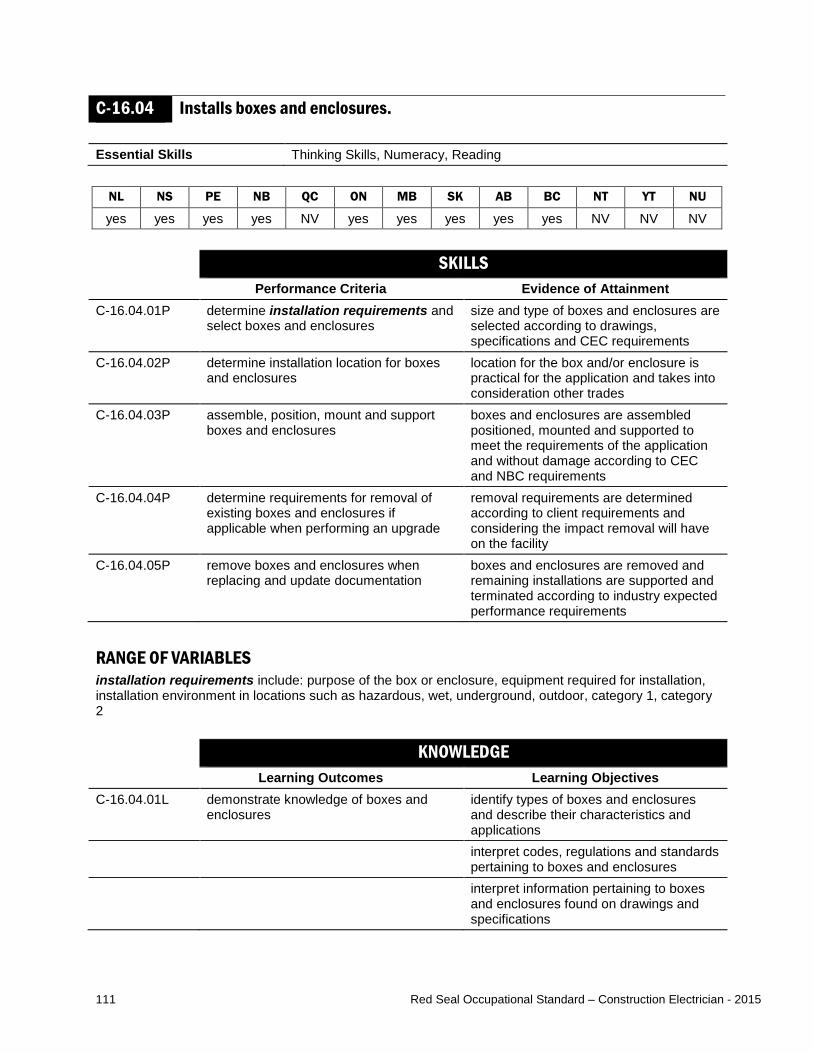
111 Red Seal Occupational Standard – Construction Electrician - 2015
C-16.04 Installs boxes and enclosures. Essential Skills Thinking Skills, Numeracy, Reading
NL NS PE NB QC ON MB SK AB BC NT YT NU
yes yes yes yes NV yes yes yes yes yes NV NV NV SKILLS
Performance Criteria Evidence of Attainment C-16.04.01P determine installation requirements and
select boxes and enclosures size and type of boxes and enclosures are selected according to drawings, specifications and CEC requirements
C-16.04.02P determine installation location for boxes and enclosures
location for the box and/or enclosure is practical for the application and takes into consideration other trades
C-16.04.03P assemble, position, mount and support boxes and enclosures
boxes and enclosures are assembled positioned, mounted and supported to meet the requirements of the application and without damage according to CEC and NBC requirements
C-16.04.04P determine requirements for removal of existing boxes and enclosures if applicable when performing an upgrade
removal requirements are determined according to client requirements and considering the impact removal will have on the facility
C-16.04.05P remove boxes and enclosures when replacing and update documentation
boxes and enclosures are removed and remaining installations are supported and terminated according to industry expected performance requirements
RANGE OF VARIABLES installation requirements include: purpose of the box or enclosure, equipment required for installation, installation environment in locations such as hazardous, wet, underground, outdoor, category 1, category 2 KNOWLEDGE
Learning Outcomes Learning Objectives C-16.04.01L demonstrate knowledge of boxes and
enclosures identify types of boxes and enclosures and describe their characteristics and applications
interpret codes, regulations and standards pertaining to boxes and enclosures
interpret information pertaining to boxes and enclosures found on drawings and specifications

112 Red Seal Occupational Standard – Construction Electrician - 2015
C-16.04.02L demonstrate knowledge of procedures used to remove and/or install and support boxes and enclosures
identify the considerations and requirements for removal of boxes and enclosures
identify the considerations and requirements for selecting boxes and enclosures
describe the procedures used to remove boxes and enclosures
describe the procedures used to install and support boxes and enclosures
RANGE OF VARIABLES considerations include: volume, environment, accessibility, size of raceway or cable entering the box or enclosure, CSA / NEMA classification
C-16.05 Performs servicing and maintenance of raceways, cables and enclosures. Essential Skills Digital Technology, Oral Communication, Document Use
NL NS PE NB QC ON MB SK AB BC NT YT NU
yes yes yes yes NV yes yes yes yes yes NV NV NV SKILLS
Performance Criteria Evidence of Attainment C-16.05.01P conduct field assessments using
diagnostic and test equipment and record results
diagnostic and test equipment that match the testing requirements is used and test results are recorded
C-16.05.02P determine source of malfunction based on field assessment
source of malfunction is identified
C-16.05.03P repair and/or replace malfunctioning component
malfunctioning component is repaired and/or replaced and system is returned to original state
C-16.05.04P conducts tests of conductors and cables and record results
diagnostic and test equipment that match the testing requirements is used and test results are recorded
C-16.05.05P re-torque terminations and test conductors for excessive heating
terminations are re-torqued according to manufacturers’ specifications and required documentation of torquing and test results is completed
RANGE OF VARIABLES field assessments include: sensory and technical inspections diagnostic and test equipment includes: megohmeters, multimeters, thermographic imaging devices, phase rotation meters, cable locators
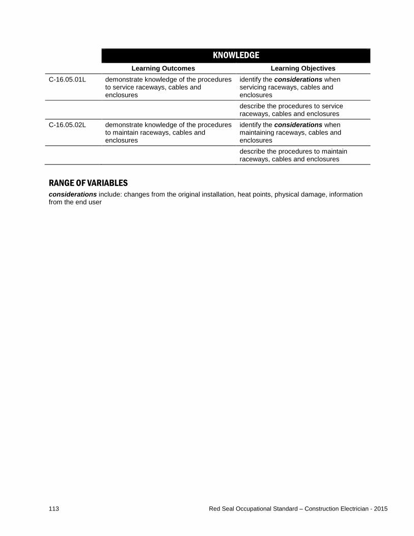
113 Red Seal Occupational Standard – Construction Electrician - 2015
KNOWLEDGE Learning Outcomes Learning Objectives
C-16.05.01L demonstrate knowledge of the procedures to service raceways, cables and enclosures
identify the considerations when servicing raceways, cables and enclosures
describe the procedures to service raceways, cables and enclosures
C-16.05.02L demonstrate knowledge of the procedures to maintain raceways, cables and enclosures
identify the considerations when maintaining raceways, cables and enclosures
describe the procedures to maintain raceways, cables and enclosures
RANGE OF VARIABLES considerations include: changes from the original installation, heat points, physical damage, information from the end user
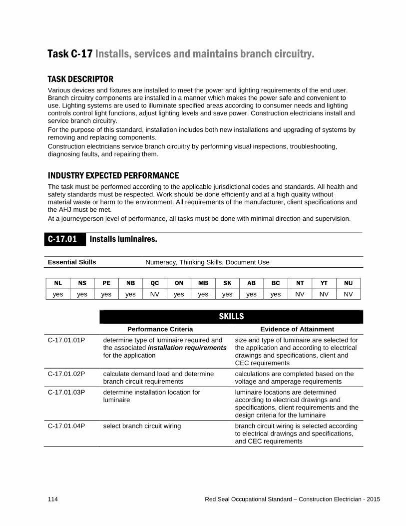
114 Red Seal Occupational Standard – Construction Electrician - 2015
Task C-17 Installs, services and maintains branch circuitry. TASK DESCRIPTOR Various devices and fixtures are installed to meet the power and lighting requirements of the end user. Branch circuitry components are installed in a manner which makes the power safe and convenient to use. Lighting systems are used to illuminate specified areas according to consumer needs and lighting controls control light functions, adjust lighting levels and save power. Construction electricians install and service branch circuitry. For the purpose of this standard, installation includes both new installations and upgrading of systems by removing and replacing components. Construction electricians service branch circuitry by performing visual inspections, troubleshooting, diagnosing faults, and repairing them. INDUSTRY EXPECTED PERFORMANCE The task must be performed according to the applicable jurisdictional codes and standards. All health and safety standards must be respected. Work should be done efficiently and at a high quality without material waste or harm to the environment. All requirements of the manufacturer, client specifications and the AHJ must be met. At a journeyperson level of performance, all tasks must be done with minimal direction and supervision.
C-17.01 Installs luminaires. Essential Skills Numeracy, Thinking Skills, Document Use
NL NS PE NB QC ON MB SK AB BC NT YT NU
yes yes yes yes NV yes yes yes yes yes NV NV NV SKILLS
Performance Criteria Evidence of Attainment C-17.01.01P
determine type of luminaire required and the associated installation requirements for the application
size and type of luminaire are selected for the application and according to electrical drawings and specifications, client and CEC requirements
C-17.01.02P calculate demand load and determine branch circuit requirements
calculations are completed based on the voltage and amperage requirements
C-17.01.03P determine installation location for luminaire
luminaire locations are determined according to electrical drawings and specifications, client requirements and the design criteria for the luminaire
C-17.01.04P select branch circuit wiring branch circuit wiring is selected according to electrical drawings and specifications, and CEC requirements
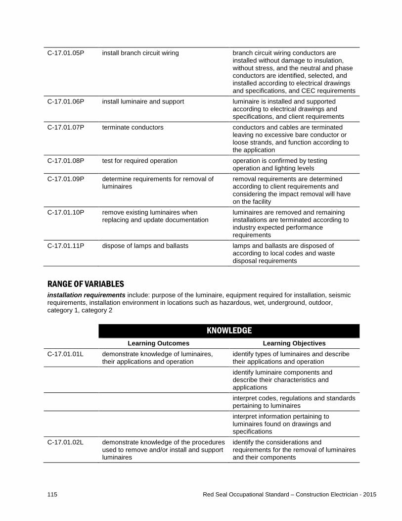
115 Red Seal Occupational Standard – Construction Electrician - 2015
C-17.01.05P install branch circuit wiring branch circuit wiring conductors are installed without damage to insulation, without stress, and the neutral and phase conductors are identified, selected, and installed according to electrical drawings and specifications, and CEC requirements
C-17.01.06P install luminaire and support luminaire is installed and supported according to electrical drawings and specifications, and client requirements
C-17.01.07P terminate conductors conductors and cables are terminated leaving no excessive bare conductor or loose strands, and function according to the application
C-17.01.08P test for required operation operation is confirmed by testing operation and lighting levels
C-17.01.09P determine requirements for removal of luminaires
removal requirements are determined according to client requirements and considering the impact removal will have on the facility
C-17.01.10P remove existing luminaires when replacing and update documentation
luminaires are removed and remaining installations are terminated according to industry expected performance requirements
C-17.01.11P dispose of lamps and ballasts lamps and ballasts are disposed of according to local codes and waste disposal requirements
RANGE OF VARIABLES installation requirements include: purpose of the luminaire, equipment required for installation, seismic requirements, installation environment in locations such as hazardous, wet, underground, outdoor, category 1, category 2 KNOWLEDGE
Learning Outcomes Learning Objectives C-17.01.01L demonstrate knowledge of luminaires,
their applications and operation identify types of luminaires and describe their applications and operation
identify luminaire components and describe their characteristics and applications
interpret codes, regulations and standards pertaining to luminaires
interpret information pertaining to luminaires found on drawings and specifications
C-17.01.02L demonstrate knowledge of the procedures used to remove and/or install and support luminaires
identify the considerations and requirements for the removal of luminaires and their components
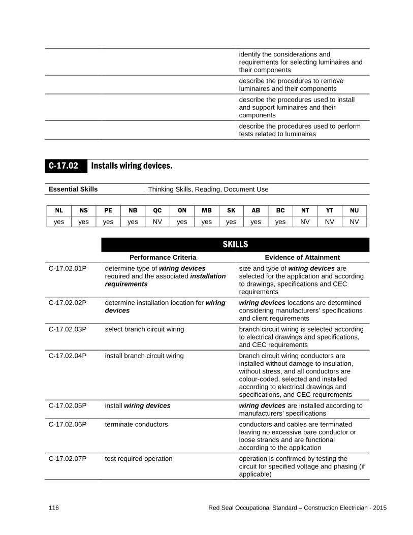
116 Red Seal Occupational Standard – Construction Electrician - 2015
identify the considerations and requirements for selecting luminaires and their components
describe the procedures to remove luminaires and their components
describe the procedures used to install and support luminaires and their components
describe the procedures used to perform tests related to luminaires
C-17.02 Installs wiring devices. Essential Skills Thinking Skills, Reading, Document Use
NL NS PE NB QC ON MB SK AB BC NT YT NU
yes yes yes yes NV yes yes yes yes yes NV NV NV SKILLS
Performance Criteria Evidence of Attainment C-17.02.01P determine type of wiring devices
required and the associated installation requirements
size and type of wiring devices are selected for the application and according to drawings, specifications and CEC requirements
C-17.02.02P determine installation location for wiring devices
wiring devices locations are determined considering manufacturers’ specifications and client requirements
C-17.02.03P select branch circuit wiring branch circuit wiring is selected according to electrical drawings and specifications, and CEC requirements
C-17.02.04P install branch circuit wiring branch circuit wiring conductors are installed without damage to insulation, without stress, and all conductors are colour-coded, selected and installed according to electrical drawings and specifications, and CEC requirements
C-17.02.05P install wiring devices wiring devices are installed according to manufacturers’ specifications
C-17.02.06P terminate conductors conductors and cables are terminated leaving no excessive bare conductor or loose strands and are functional according to the application
C-17.02.07P test required operation operation is confirmed by testing the circuit for specified voltage and phasing (if applicable)

117 Red Seal Occupational Standard – Construction Electrician - 2015
C-17.02.08P select and install faceplate if applicable faceplate is selected and installed to the industry expected performance requirements
C-17.02.09P determine requirements for removal of wiring devices
removal requirements are determined according to client requirements and considering the impact removal will have on the facility
C-17.02.10P remove existing wiring devices when replacing and update documentation
wiring devices are removed and remaining installations are terminated according to industry expected performance requirements
RANGE OF VARIABLES wiring devices include: lampholders, switches, timers, sensors, relays, controllers, safety switches, power outlets, receptacles installation requirements include: purpose of the wiring device, equipment required for installation, installation environment in locations such as hazardous, wet, outdoor, category 1, category 2 KNOWLEDGE
Learning Outcomes Learning Objectives C-17.02.01L demonstrate knowledge of wiring
devices, their applications and operation identify types of wiring devices and describe their applications and operation
interpret codes, regulations and standards pertaining to wiring devices
interpret information pertaining to wiring devices found on drawings and specifications
C-17.02.02L demonstrate knowledge of the procedures used to remove and install wiring devices
identify the considerations and requirements for the removal of wiring devices
identify the considerations and requirements for selecting wiring devices
describe the procedures to remove wiring devices
describe the procedures used to install wiring devices
RANGE OF VARIABLES wiring devices include: lampholders, switches, timers, sensors, relays, controllers, safety switches, power outlets, receptacles
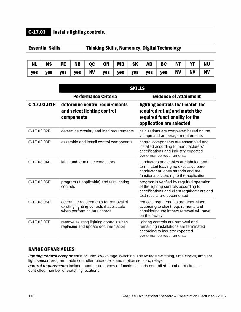
118 Red Seal Occupational Standard – Construction Electrician - 2015
C-17.03 Installs lighting controls. Essential Skills Thinking Skills, Numeracy, Digital Technology
NL NS PE NB QC ON MB SK AB BC NT YT NU yes yes yes yes NV yes yes yes yes yes NV NV NV
SKILLS
Performance Criteria Evidence of Attainment C-17.03.01P determine control requirements
and select lighting control components
lighting controls that match the required rating and match the required functionality for the application are selected
C-17.03.02P determine circuitry and load requirements calculations are completed based on the voltage and amperage requirements
C-17.03.03P assemble and install control components control components are assembled and installed according to manufacturers’ specifications and industry expected performance requirements
C-17.03.04P label and terminate conductors conductors and cables are labeled and terminated leaving no excessive bare conductor or loose strands and are functional according to the application
C-17.03.05P program (if applicable) and test lighting controls
program is verified by required operation of the lighting controls according to specifications and client requirements and test results are documented
C-17.03.06P determine requirements for removal of existing lighting controls if applicable when performing an upgrade
removal requirements are determined according to client requirements and considering the impact removal will have on the facility
C-17.03.07P remove existing lighting controls when replacing and update documentation
lighting controls are removed and remaining installations are terminated according to industry expected performance requirements
RANGE OF VARIABLES lighting control components include: low-voltage switching, line voltage switching, time clocks, ambient light sensor, programmable controller, photo cells and motion sensors, relays control requirements include: number and types of functions, loads controlled, number of circuits controlled, number of switching locations

119 Red Seal Occupational Standard – Construction Electrician - 2015
KNOWLEDGE Learning Outcomes Learning Objectives
C-17.03.01L demonstrate knowledge of types of lighting control components, their applications and operation
identify types of lighting control components and describe their characteristics and applications
interpret information pertaining to lighting control components found on drawings and specifications
interpret codes and regulations pertaining to lighting control components
C-17.03.02L demonstrate knowledge of the procedures used to remove and/or install, connect and test lighting control components
identify considerations and requirements for removal of lighting control components
identify considerations and requirements for selecting lighting control components
describe the procedures used to remove lighting control components
describe the procedures used to install lighting control components
describe the procedures used to connect lighting control components
describe the procedures used to test lighting control components
RANGE OF VARIABLES lighting control components include: low-voltage switching, line voltage switching, time clocks, ambient light sensor, programmable controller, photo cells and motion sensors, relays
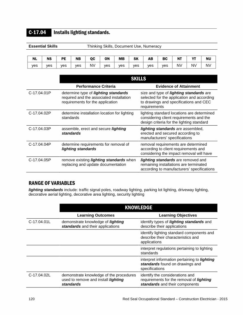
120 Red Seal Occupational Standard – Construction Electrician - 2015
C-17.04 Installs lighting standards. Essential Skills Thinking Skills, Document Use, Numeracy
NL NS PE NB QC ON MB SK AB BC NT YT NU
yes yes yes yes NV yes yes yes yes yes NV NV NV SKILLS
Performance Criteria Evidence of Attainment C-17.04.01P determine type of lighting standards
required and the associated installation requirements for the application
size and type of lighting standards are selected for the application and according to drawings and specifications and CEC requirements
C-17.04.02P determine installation location for lighting standards
lighting standard locations are determined considering client requirements and the design criteria for the lighting standard
C-17.04.03P assemble, erect and secure lighting standards
lighting standards are assembled, erected and secured according to manufacturers’ specifications
C-17.04.04P determine requirements for removal of lighting standards
removal requirements are determined according to client requirements and considering the impact removal will have
C-17.04.05P remove existing lighting standards when replacing and update documentation
lighting standards are removed and remaining installations are terminated according to manufacturers’ specifications
RANGE OF VARIABLES lighting standards include: traffic signal poles, roadway lighting, parking lot lighting, driveway lighting, decorative aerial lighting, decorative area lighting, security lighting KNOWLEDGE
Learning Outcomes Learning Objectives C-17.04.01L demonstrate knowledge of lighting
standards and their applications identify types of lighting standards and describe their applications
identify lighting standard components and describe their characteristics and applications
interpret regulations pertaining to lighting standards
interpret information pertaining to lighting standards found on drawings and specifications
C-17.04.02L demonstrate knowledge of the procedures used to remove and install lighting standards
identify the considerations and requirements for the removal of lighting standards and their components

121 Red Seal Occupational Standard – Construction Electrician - 2015
identify the considerations and requirements for selecting lighting standards and their components
describe the procedures used for rigging and hoisting lighting standards for erection and dismantling
describe the procedures to remove lighting standards and their components
describe the procedures used to assemble, erect and secure lighting standards and their components
RANGE OF VARIABLES lighting standards include: traffic signal poles, roadway lighting, parking lot lighting, driveway lighting, decorative aerial lighting, decorative area lighting, security lighting
C-17.05 Performs servicing of branch circuitry. Essential Skills Digital Technology, Thinking Skills, Reading
NL NS PE NB QC ON MB SK AB BC NT YT NU
yes yes yes yes NV yes yes yes yes yes NV NV NV SKILLS
Performance Criteria Evidence of Attainment C-17.05.01P conduct field assessments using
diagnostic and test equipment to determine source of malfunction
source of malfunction is identified based on inspection and diagnostic and test equipment results
C-17.05.02P identify and remove defective components of branch circuitry
defective component is removed without damage to system or other components
C-17.05.03P select replacement components replacement components match the application
C-17.05.04P install replacement components components are installed with minimal disruptions and interruptions
C-17.05.05P conduct tests of branch circuitry after repair
branch circuitry is functional and connected according to manufacturers’ specifications
RANGE OF VARIABLES field assessments include: sensory and technical inspections diagnostic and test equipment includes: multimeters, thermographic imaging devices branch circuitry, for the purpose of this sub-task, does not include airport runway lighting or traffic signals, which are covered in sub-tasks 17.06 and 17.07

122 Red Seal Occupational Standard – Construction Electrician - 2015
KNOWLEDGE Learning Outcomes Learning Objectives
C-17.05.01L demonstrate knowledge of branch circuitry and branch circuitry components
identify types of branch circuitry components and describe their applications and operation
C-17.05.02L demonstrate knowledge of the procedures used to service branch circuitry and branch circuitry components
describe the procedures used to diagnose branch circuitry components
describe the procedures used to repair/replace branch circuitry components
RANGE OF VARIABLES branch circuitry, for the purpose of this sub-task, does not include airport runway lighting or traffic signals, which are covered in sub-tasks 17.06 and 17.07
C-17.06 Installs, services and maintains airport runway lighting systems. Essential Skills Thinking Skills, Numeracy, Document Use
NL NS PE NB QC ON MB SK AB BC NT YT NU
yes yes yes yes NV yes yes yes yes yes NV NV NV SKILLS
Performance Criteria Evidence of Attainment C-17.06.01P determine installation requirements and
select airport runway lighting system components and control components
airport runway lighting system components and control components are selected according to rating, the required functionality for the application, and according to drawings, specifications and CEC requirements
C-17.06.02P determine circuitry and load requirements calculations are completed based on the voltage and amperage requirements
C-17.06.03P assemble and install airport runway lighting system components
airport runway lighting system components are assembled and installed according to manufacturers’ specifications
C-17.06.04P label and terminate conductors conductors and cables are labeled and terminated using termination kits that match the conductor and terminal requirements
C-17.06.05P test lighting and controls tests verify specified operation of the lighting and controls, and test results are documented
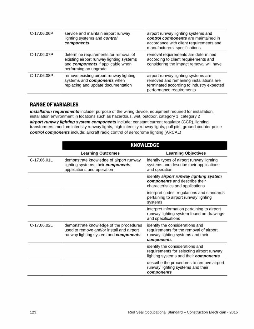
123 Red Seal Occupational Standard – Construction Electrician - 2015
C-17.06.06P service and maintain airport runway lighting systems and control components
airport runway lighting systems and control components are maintained in accordance with client requirements and manufacturers’ specifications
C-17.06.07P determine requirements for removal of existing airport runway lighting systems and components if applicable when performing an upgrade
removal requirements are determined according to client requirements and considering the impact removal will have
C-17.06.08P remove existing airport runway lighting systems and components when replacing and update documentation
airport runway lighting systems are removed and remaining installations are terminated according to industry expected performance requirements
RANGE OF VARIABLES installation requirements include: purpose of the wiring device, equipment required for installation, installation environment in locations such as hazardous, wet, outdoor, category 1, category 2 airport runway lighting system components include: constant current regulator (CCR), lighting transformers, medium intensity runway lights, high intensity runway lights, pull pits, ground counter poise control components include: aircraft radio control of aerodrome lighting (ARCAL) KNOWLEDGE
Learning Outcomes Learning Objectives C-17.06.01L demonstrate knowledge of airport runway
lighting systems, their components, applications and operation
identify types of airport runway lighting systems and describe their applications and operation
identify airport runway lighting system components and describe their characteristics and applications
interpret codes, regulations and standards pertaining to airport runway lighting systems
interpret information pertaining to airport runway lighting system found on drawings and specifications
C-17.06.02L demonstrate knowledge of the procedures used to remove and/or install and airport runway lighting system and components
identify the considerations and requirements for the removal of airport runway lighting systems and their components
identify the considerations and requirements for selecting airport runway lighting systems and their components
describe the procedures to remove airport runway lighting systems and their components
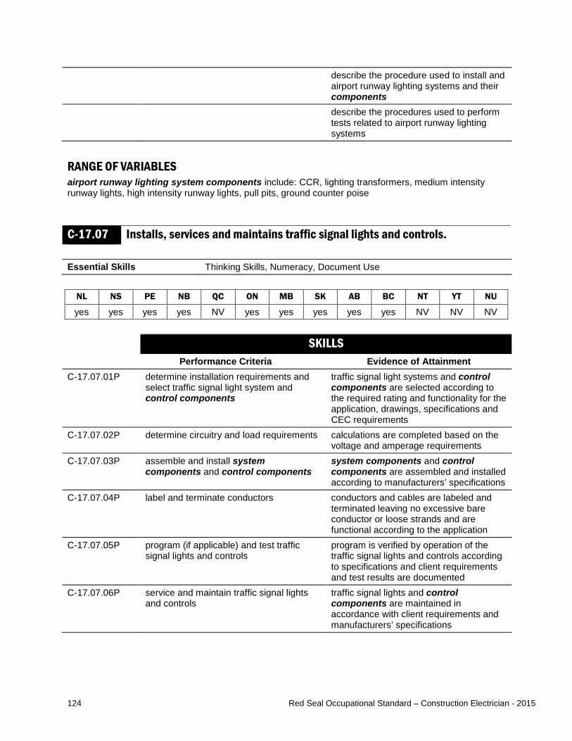
124 Red Seal Occupational Standard – Construction Electrician - 2015
describe the procedure used to install and airport runway lighting systems and their components
describe the procedures used to perform tests related to airport runway lighting systems
RANGE OF VARIABLES airport runway lighting system components include: CCR, lighting transformers, medium intensity runway lights, high intensity runway lights, pull pits, ground counter poise
C-17.07 Installs, services and maintains traffic signal lights and controls. Essential Skills Thinking Skills, Numeracy, Document Use
NL NS PE NB QC ON MB SK AB BC NT YT NU
yes yes yes yes NV yes yes yes yes yes NV NV NV SKILLS
Performance Criteria Evidence of Attainment C-17.07.01P determine installation requirements and
select traffic signal light system and control components
traffic signal light systems and control components are selected according to the required rating and functionality for the application, drawings, specifications and CEC requirements
C-17.07.02P determine circuitry and load requirements calculations are completed based on the voltage and amperage requirements
C-17.07.03P assemble and install system components and control components
system components and control components are assembled and installed according to manufacturers’ specifications
C-17.07.04P label and terminate conductors conductors and cables are labeled and terminated leaving no excessive bare conductor or loose strands and are functional according to the application
C-17.07.05P program (if applicable) and test traffic signal lights and controls
program is verified by operation of the traffic signal lights and controls according to specifications and client requirements and test results are documented
C-17.07.06P service and maintain traffic signal lights and controls
traffic signal lights and control components are maintained in accordance with client requirements and manufacturers’ specifications

125 Red Seal Occupational Standard – Construction Electrician - 2015
C-17.07.07P determine requirements for removal of existing traffic signal light systems and control components if applicable when performing an upgrade
removal requirements are determined according to client requirements and considering the impact of removal
C-17.07.08P remove existing traffic signal lights and control components when replacing and update documentation
traffic signal lights and control components are removed and remaining installations are terminated
RANGE OF VARIABLES system components include: signal heads, luminaires, pedestrian push buttons, audible devices, lighting standards, signal arms, pre-cast bases, traffic signal cables control components include: vehicle sensors, cameras, traffic signal controllers, modems KNOWLEDGE
Learning Outcomes Learning Objectives C-17.07.01L demonstrate knowledge of types of traffic
signal light systems and control components, their applications and operation
identify types of traffic signal light systems and control components and describe their characteristics and applications
interpret information pertaining to traffic signal light systems and controls found on drawings and specifications
interpret codes and regulations pertaining to traffic signal light systems and control components
C-17.07.02L demonstrate knowledge of the procedures used to remove and/or install, connect and test traffic signal light systems and control components
identify considerations and requirements for removal of traffic signal light systems and control components
identify considerations and requirements for selecting traffic signal light systems and control components
describe the procedures used to remove traffic signal lights and control components
describe the procedures used to install traffic signal light systems and control components
describe the procedures used to connect traffic signal light systems and control components
describe the procedures used to service and maintain traffic signal light systems and control components
describe the procedures used to test and document traffic signal light systems and control components

126 Red Seal Occupational Standard – Construction Electrician - 2015
RANGE OF VARIABLES control components include: vehicle sensors, cameras, traffic signal controllers, modems
Task C-18 Installs, services and maintains power and controls for heating, ventilation and air-conditioning (HVAC) systems. TASK DESCRIPTOR Cooling and ventilation systems can be installed by other trades, but are electrically connected by construction electricians. Construction electricians connect HVAC systems and install, service and maintain HVAC system controls. For the purpose of this standard, installation includes both new installations and upgrading of systems by removing and replacing components. Construction electricians service HVAC system controls by performing visual inspections, troubleshooting, diagnosing faults, and repairing them. They also perform maintenance to ensure HVAC system controls are in good operating condition. INDUSTRY EXPECTED PERFORMANCE The task must be performed according to the applicable jurisdictional codes and standards. All health and safety standards must be respected. Work should be done efficiently and at a high quality without material waste or harm to the environment. All requirements of the manufacturer, client specifications and the AHJ must be met. At a journeyperson level of performance, all tasks must be done with minimal direction and supervision. C-18.01 Connects HVAC systems. Essential Skills Document Use, Thinking Skills, Numeracy
NL NS PE NB QC ON MB SK AB BC NT YT NU
yes yes yes yes NV yes yes yes yes yes NV NV NV SKILLS
Performance Criteria Evidence of Attainment C-18.01.01P determine connected load requirements connected load requirements are
determined by interpreting nameplate ratings
C-18.01.02P select branch circuit wiring including disconnect means if required
branch circuit wiring and disconnect means are selected according to drawings, specifications, and client and CEC requirements

127 Red Seal Occupational Standard – Construction Electrician - 2015
C-18.01.03P install branch circuit wiring including disconnect means if required
branch circuit wiring conductors are installed without damage to insulation, without stress and the neutral and phase conductors are colour-coded, selected and installed according to electrical drawings and specifications, and CEC requirements
C-18.01.04P terminate and label conductors conductors and cables are labeled and terminated leaving no excessive bare conductor or loose strands, and phased and torqued according to electrical, client and manufacturers’ specifications
C-18.01.05P test operation operation is confirmed by testing the circuit for specified voltage, amperage and rotation
C-18.01.06P determine requirements for disconnection of HVAC systems
disconnection requirements are determined according to client requirements and considering the impact disconnection will have on the facility
C-18.01.07P disconnect existing HVAC systems when replacing and update documentation
HVAC systems are disconnected and remaining installations are terminated
KNOWLEDGE
Learning Outcomes Learning Objectives C-18.01.01L demonstrate knowledge of HVAC
systems, their applications and operation identify types of HVAC systems and describe their characteristics and applications
interpret information pertaining to HVAC systems found on drawings, specifications and nameplates
interpret codes, standards and regulations pertaining to HVAC systems
C-18.01.02L demonstrate knowledge of the procedures to disconnect and/or connect HVAC systems
identify considerations and requirements for disconnecting HVAC systems and their components
identify considerations and requirements for connecting HVAC systems and their components
describe the procedures used to connect HVAC systems and their components
describe the procedures used to disconnect HVAC systems and their components
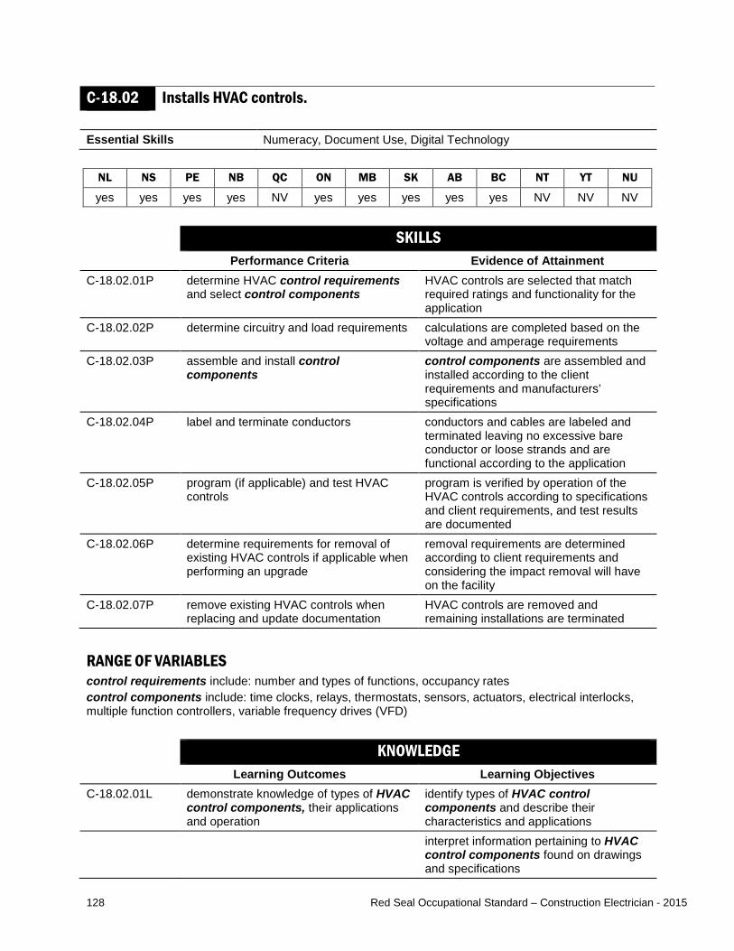
128 Red Seal Occupational Standard – Construction Electrician - 2015
C-18.02 Installs HVAC controls. Essential Skills Numeracy, Document Use, Digital Technology
NL NS PE NB QC ON MB SK AB BC NT YT NU
yes yes yes yes NV yes yes yes yes yes NV NV NV SKILLS
Performance Criteria Evidence of Attainment C-18.02.01P determine HVAC control requirements
and select control components HVAC controls are selected that match required ratings and functionality for the application
C-18.02.02P determine circuitry and load requirements calculations are completed based on the voltage and amperage requirements
C-18.02.03P assemble and install control components
control components are assembled and installed according to the client requirements and manufacturers’ specifications
C-18.02.04P label and terminate conductors conductors and cables are labeled and terminated leaving no excessive bare conductor or loose strands and are functional according to the application
C-18.02.05P program (if applicable) and test HVAC controls
program is verified by operation of the HVAC controls according to specifications and client requirements, and test results are documented
C-18.02.06P determine requirements for removal of existing HVAC controls if applicable when performing an upgrade
removal requirements are determined according to client requirements and considering the impact removal will have on the facility
C-18.02.07P remove existing HVAC controls when replacing and update documentation
HVAC controls are removed and remaining installations are terminated
RANGE OF VARIABLES control requirements include: number and types of functions, occupancy rates control components include: time clocks, relays, thermostats, sensors, actuators, electrical interlocks, multiple function controllers, variable frequency drives (VFD) KNOWLEDGE
Learning Outcomes Learning Objectives C-18.02.01L demonstrate knowledge of types of HVAC
control components, their applications and operation
identify types of HVAC control components and describe their characteristics and applications
interpret information pertaining to HVAC control components found on drawings and specifications

129 Red Seal Occupational Standard – Construction Electrician - 2015
interpret codes and regulations pertaining to HVAC control components
C-18.02.02L demonstrate knowledge of the procedures used to remove and/or install, connect and test HVAC control components
identify the considerations and requirements for removal of HVAC control components
identify considerations and requirements for selecting HVAC control components
describe the procedures used to remove HVAC control components
describe the procedures used to install HVAC control components
describe the procedures used to connect HVAC control components
describe the procedures used to test HVAC control components
RANGE OF VARIABLES HVAC control components include: time clocks, relays, thermostats, sensors, actuators, electrical interlocks, multiple function controllers, VFDs
C-18.03 Performs servicing and maintenance of HVAC systems and controls. Essential Skills Digital Technology, Thinking Skills, Document Use
NL NS PE NB QC ON MB SK AB BC NT YT NU
yes yes yes yes NV yes yes yes yes yes NV NV NV SKILLS
Performance Criteria Evidence of Attainment C-18.03.01P conduct field assessments using
diagnostic and test equipment to determine source of malfunction
source of malfunction is identified based on inspection and diagnostic and test equipment results
C-18.03.02P identify and remove defective electrical components and equipment of HVAC systems and controls
defective component is removed without damage to system or other components
C-18.03.03P repair malfunctioning electrical components and equipment
repaired electrical components and equipment are operational
C-18.03.04P select replacement electrical components and equipment
replacement electrical components and equipment (OEM replacement when mandated) match the application
C-18.03.05P install replacement electrical components and equipment and reprogram if necessary
electrical components and equipment are installed with minimal disruptions and interruptions

130 Red Seal Occupational Standard – Construction Electrician - 2015
C-18.03.06P conduct tests of HVAC systems and controls after repair
HVAC systems and controls are connected and function according to manufacturers’ and client specifications
C-18.03.07P record tests in maintenance schedule operational problems are identified in maintenance schedule data with detailed notations
RANGE OF VARIABLES field assessments include: sensory and technical inspections diagnostic and test equipment includes: multimeters, clamp ammeters equipment includes: air handling motors, evaporator fans, condenser fans HVAC systems and controls include: chiller system, compressor unit, fan motor, thermostat, pressure switch, temperature switch, flow switch, level switch, VFDs, cooling tower heater, chiller heater KNOWLEDGE
Learning Outcomes Learning Objectives C-18.03.01L demonstrate knowledge of HVAC
systems and controls identify types of HVAC systems and controls and describe their applications and operation
identify HVAC system and control components and describe their characteristics and applications
C-18.03.02L demonstrate knowledge of the procedures used to service HVAC systems and controls
describe the procedures used to diagnose HVAC systems and controls and their components
describe the procedures used to repair HVAC systems and controls and their components
C-18.03.03L demonstrate knowledge of the procedures used to maintain HVAC systems and controls
describe the procedures used to maintain HVAC systems and controls and their components
RANGE OF VARIABLES HVAC systems and controls include: chiller system, compressor unit, fan motor, thermostat, pressure switch, temperature switch, flow switch, level switch, VFDs, cooling tower heater, chiller heater

131 Red Seal Occupational Standard – Construction Electrician - 2015
Task C-19 Installs, services and maintains electric heating systems. TASK DESCRIPTOR Electric heating systems and their associated control devices are installed and connected by construction electricians. For the purpose of this standard, installation includes both new installations and upgrading of systems by removing and replacing components. Construction electricians service electric heating systems and their associated controls by performing visual inspections, troubleshooting, diagnosing faults, and repairing them. They also perform maintenance to ensure electric heating systems and their associated control devices are in good operating condition. INDUSTRY EXPECTED PERFORMANCE The task must be performed according to the applicable jurisdictional codes and standards. All health and safety standards must be respected. Work should be done efficiently and at a high quality without material waste or harm to the environment. All requirements of the manufacturer, client specifications and the AHJ must be met. At a journeyperson level of performance, all tasks must be done with minimal direction and supervision.
C-19.01 Installs electric heating systems. Essential Skills Thinking Skills, Numeracy, Document Use
NL NS PE NB QC ON MB SK AB BC NT YT NU
yes yes yes yes NV yes yes yes yes yes NV NV NV SKILLS
Performance Criteria Evidence of Attainment C-19.01.01P determine type of electric heating
system required and the associated installation requirements for the system
size and type of electric heating system are selected to match the application
C-19.01.02P calculate demand load and determine branch circuit requirements
calculations are completed based on the voltage and wattage requirements
C-19.01.03P determine installation location for heating device
heating device locations are determined considering manufacturers’ specifications and client requirements
C-19.01.04P select branch circuit wiring branch circuit wiring is selected according to drawings, specifications, client and CEC requirements
C-19.01.05P install branch circuit wiring branch circuit wiring conductors are installed without damage to insulation, without stress and the neutral and phase conductors are colour-coded, selected and installed according to electrical drawings and specifications, and CEC requirements
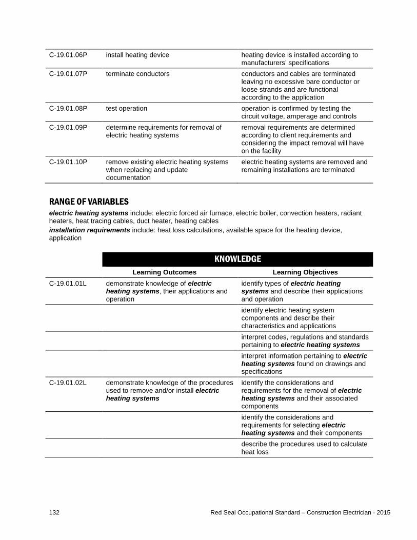
132 Red Seal Occupational Standard – Construction Electrician - 2015
C-19.01.06P install heating device heating device is installed according to manufacturers’ specifications
C-19.01.07P terminate conductors conductors and cables are terminated leaving no excessive bare conductor or loose strands and are functional according to the application
C-19.01.08P test operation operation is confirmed by testing the circuit voltage, amperage and controls
C-19.01.09P determine requirements for removal of electric heating systems
removal requirements are determined according to client requirements and considering the impact removal will have on the facility
C-19.01.10P remove existing electric heating systems when replacing and update documentation
electric heating systems are removed and remaining installations are terminated
RANGE OF VARIABLES electric heating systems include: electric forced air furnace, electric boiler, convection heaters, radiant heaters, heat tracing cables, duct heater, heating cables installation requirements include: heat loss calculations, available space for the heating device, application KNOWLEDGE
Learning Outcomes Learning Objectives C-19.01.01L demonstrate knowledge of electric
heating systems, their applications and operation
identify types of electric heating systems and describe their applications and operation
identify electric heating system components and describe their characteristics and applications
interpret codes, regulations and standards pertaining to electric heating systems
interpret information pertaining to electric heating systems found on drawings and specifications
C-19.01.02L demonstrate knowledge of the procedures used to remove and/or install electric heating systems
identify the considerations and requirements for the removal of electric heating systems and their associated components
identify the considerations and requirements for selecting electric heating systems and their components
describe the procedures used to calculate heat loss

133 Red Seal Occupational Standard – Construction Electrician - 2015
describe the procedures to remove electric heating systems and their components
describe the procedures used to install electric heating systems and their components
RANGE OF VARIABLES electric heating systems include: electric forced air furnace, electric boiler, convection heaters, radiant heaters, heat tracing cables, duct heater, heating cables
C-19.02 Installs electric heating system controls. Essential Skills Thinking Skills, Numeracy, Document Use NL NS PE NB QC ON MB SK AB BC NT YT NU yes yes yes yes NV yes yes yes yes yes NV NV NV
SKILLS Performance Criteria Evidence of Attainment
C-19.02.01P determine control requirements and select electric heating system control components
electric heating system control components are selected that match the required rating and functionality for the application
C-19.02.02P determine circuitry and load requirements calculations are completed based on the voltage and wattage requirements
C-19.02.03P assemble and install control components
control components are assembled and installed according to the client and manufacturers’ specifications
C-19.02.04P label and terminate conductors conductors and cables are labeled and terminated leaving no excessive bare conductor or loose strands and are functional according to the application
C-19.02.05P program (if applicable) and test electric heating system control components
program is verified by operation of the electric heating system control components according to specifications and client requirements
C-19.02.06P determine requirements for removal of existing electric heating system controls if applicable when performing an upgrade
removal requirements are determined according to client requirements and considering the impact removal will have on the facility
C-19.02.07P remove existing electric heating system control components when replacing and update documentation
electric heating system control components are removed and remaining installations are terminated

134 Red Seal Occupational Standard – Construction Electrician - 2015
RANGE OF VARIABLES control requirements include: number and types of functions electric heating system control components include: thermostats, heating relays, sensors, contactors, electrical interlocks, semiconductor controls, web-based controls KNOWLEDGE
Learning Outcomes Learning Objectives C-19.02.01L demonstrate knowledge of types of
electric heating system control components, their applications and operation
identify types of electric heating system control components and describe their characteristics and applications
interpret information pertaining to electric heating system control components found on drawings and specifications
interpret codes and regulations pertaining to electric heating system control components
C-19.02.02L demonstrate knowledge of the procedures used to remove and/or install, connect and test electric heating system control components
identify the considerations and requirements for removal of electric heating system control components
identify considerations and requirements for selecting electric heating system control components
describe the procedures used to remove electric heating system control components
describe the procedures used to install electric heating system control components
describe the procedures used to connect electric heating system control components
describe the procedures used to test electric heating system control components
RANGE OF VARIABLES electric heating system control components include: thermostats, heating relays, sensors, contactors, electrical interlocks, semiconductor controls, web-based controls
C-19.03 Performs servicing and maintenance of electric heating systems and controls.
Essential Skills Digital Technology, Thinking Skills, Document Use

135 Red Seal Occupational Standard – Construction Electrician - 2015
NL NS PE NB QC ON MB SK AB BC NT YT NU
yes yes yes yes NV yes yes yes yes yes NV NV NV SKILLS
Performance Criteria Evidence of Attainment C-19.03.01P conduct field assessments using
diagnostic and test equipment to determine source of malfunction
source of malfunction is identified based on inspection and diagnostic and test equipment results
C-19.03.02P identify and remove defective electric heating system components and controls
defective component is removed without damage to system or other components
C-19.03.03P select replacement components replacement components (OEM replacement when mandated) match the application
C-19.03.04P install replacement components components are installed with minimal disruptions and interruptions
C-19.03.05P conduct tests of electric heating systems and controls after repair
electric heating systems and controls are connected and functioning according to manufacturers’ and client specifications
C-19.03.06P clean and adjust components electric heating system and control components are restored to optimal conditions
C-19.03.07P record tests in maintenance schedule operational problems are identified in maintenance schedule data with detailed notations
RANGE OF VARIABLES field assessments include: sensory and technical inspections diagnostic and test equipment includes: multimeters, clamp ammeters KNOWLEDGE
Learning Outcomes Learning Objectives C-19.03.01L demonstrate knowledge of electric
heating systems and control components
identify types of electric heating systems and control components and describe their applications and operation
identify electric heating systems and control components and describe their characteristics and applications
C-19.03.02L demonstrate knowledge of the procedures used to service electric heating systems and control components
describe the procedures used to diagnose electric heating systems and control components
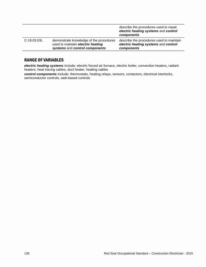
136 Red Seal Occupational Standard – Construction Electrician - 2015
describe the procedures used to repair electric heating systems and control components
C-19.03.03L demonstrate knowledge of the procedures used to maintain electric heating systems and control components
describe the procedures used to maintain electric heating systems and control components
RANGE OF VARIABLES electric heating systems include: electric forced air furnace, electric boiler, convection heaters, radiant heaters, heat tracing cables, duct heater, heating cables control components include: thermostats, heating relays, sensors, contactors, electrical interlocks, semiconductor controls, web-based controls

137 Red Seal Occupational Standard – Construction Electrician - 2015
Task C-20 Installs, services and maintains exit and emergency lighting systems. TASK DESCRIPTOR Exit and emergency lighting systems are used to facilitate safe egress from buildings during emergency situations. The systems can be powered by batteries or generators and the required size and placement are determined by building code requirements. Construction electricians install exit and emergency lighting systems. For the purpose of this standard, installation includes both new installations and upgrading of systems by removing and replacing components. Construction electricians service exit and emergency lighting systems by performing visual inspections, troubleshooting, diagnosing faults, and repairing them. They also perform maintenance to ensure exit and emergency lighting systems are in good operating condition. INDUSTRY EXPECTED PERFORMANCE The task must be performed according to the applicable jurisdictional codes and standards. All health and safety standards must be respected. Work should be done efficiently and at a high quality without material waste or harm to the environment. All requirements of the manufacturer, client specifications and the AHJ must be met. At a journeyperson level of performance, all tasks must be done with minimal direction and supervision.
C-20.01 Installs exit and emergency lighting. Essential Skills Thinking Skills, Numeracy, Document Use
NL NS PE NB QC ON MB SK AB BC NT YT NU
yes yes yes yes NV yes yes yes yes yes NV NV NV SKILLS
Performance Criteria Evidence of Attainment C-20.01.01P determine type of exit and emergency
lighting system required and the associated installation requirements
size and type of exit and emergency lighting system is selected for the application according to drawings, specifications and building code requirements
C-20.01.02P calculate connected load and determine branch circuit requirements
calculations are completed based on the voltage and wattage requirements with consideration of voltage drop
C-20.01.03P determine installation location for exit and emergency lighting system
exit and emergency lighting system locations are determined according to drawings and specifications, and AHJ requirements
C-20.01.04P select branch circuit wiring branch circuit wiring is selected according to CEC requirements
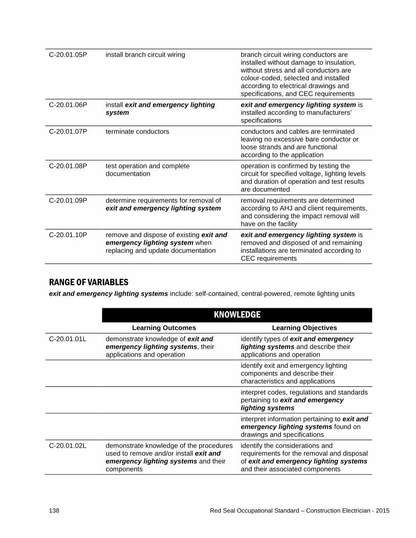
138 Red Seal Occupational Standard – Construction Electrician - 2015
C-20.01.05P install branch circuit wiring branch circuit wiring conductors are installed without damage to insulation, without stress and all conductors are colour-coded, selected and installed according to electrical drawings and specifications, and CEC requirements
C-20.01.06P install exit and emergency lighting system
exit and emergency lighting system is installed according to manufacturers’ specifications
C-20.01.07P terminate conductors conductors and cables are terminated leaving no excessive bare conductor or loose strands and are functional according to the application
C-20.01.08P test operation and complete documentation
operation is confirmed by testing the circuit for specified voltage, lighting levels and duration of operation and test results are documented
C-20.01.09P determine requirements for removal of exit and emergency lighting system
removal requirements are determined according to AHJ and client requirements, and considering the impact removal will have on the facility
C-20.01.10P remove and dispose of existing exit and emergency lighting system when replacing and update documentation
exit and emergency lighting system is removed and disposed of and remaining installations are terminated according to CEC requirements
RANGE OF VARIABLES exit and emergency lighting systems include: self-contained, central-powered, remote lighting units KNOWLEDGE
Learning Outcomes Learning Objectives C-20.01.01L demonstrate knowledge of exit and
emergency lighting systems, their applications and operation
identify types of exit and emergency lighting systems and describe their applications and operation
identify exit and emergency lighting components and describe their characteristics and applications
interpret codes, regulations and standards pertaining to exit and emergency lighting systems
interpret information pertaining to exit and emergency lighting systems found on drawings and specifications
C-20.01.02L demonstrate knowledge of the procedures used to remove and/or install exit and emergency lighting systems and their components
identify the considerations and requirements for the removal and disposal of exit and emergency lighting systems and their associated components

139 Red Seal Occupational Standard – Construction Electrician - 2015
identify the considerations and requirements for selecting exit and emergency lighting systems and their components
describe the procedures to remove exit and emergency lighting systems and their components
describe the procedure used to install exit and emergency lighting systems and their components
describe the procedures used to test exit and emergency lighting systems and their components and complete the required documentation
RANGE OF VARIABLES exit and emergency lighting systems include: self-contained, central-powered, remote lighting units
C-20.02 Performs servicing and maintenance of exit and emergency lighting systems. Essential Skills Digital Technology, Document Use, Thinking Skills
NL NS PE NB QC ON MB SK AB BC NT YT NU
yes yes yes yes NV yes yes yes yes yes NV NV NV SKILLS
Performance Criteria Evidence of Attainment C-20.02.01P conduct field assessments using
diagnostic and test equipment to determine source of malfunction
source of malfunction is identified based on inspection and diagnostic and test equipment results
C-20.02.02P identify, remove and dispose of defective components of exit and emergency lighting systems
defective component is removed and disposed of without damage to system or other components
C-20.02.03P repair malfunctioning components repaired components are operational C-20.02.04P select replacement components replacement components (OEM
replacement when mandated) match the application
C-20.02.05P install replacement components components are installed with minimal disruptions and interruptions

140 Red Seal Occupational Standard – Construction Electrician - 2015
C-20.02.06P conduct tests of exit and emergency lighting system after repair
exit and emergency lighting system is functional and tested to ensure AHJ-mandated lighting levels and duration of operation
C-20.02.07P record tests in maintenance schedule operational problems are identified in maintenance schedule data with detailed notations
RANGE OF VARIABLES field assessments include: sensory and technical inspections diagnostic and test equipment includes: multimeters exit and emergency lighting systems include: self-contained, central-powered, remote lighting units KNOWLEDGE
Learning Outcomes Learning Objectives C-20.02.01L demonstrate knowledge of exit and
emergency lighting systems, their applications and operation
identify types of exit and emergency lighting systems and describe their applications and operation
identify exit and emergency lighting system components and describe their applications and operation
C-20.02.02L demonstrate knowledge of the procedures used to service exit and emergency lighting systems
describe the procedures used to diagnose exit and emergency lighting systems and their components
describe the procedures used to repair/replace exit and emergency lighting systems and their components
C-20.02.03L demonstrate knowledge of the procedures used to maintain exit and emergency lighting systems
describe the procedures used to maintain exit and emergency lighting systems and their components
RANGE OF VARIABLES exit and emergency lighting systems include: self-contained, central-powered, remote lighting units

141 Red Seal Occupational Standard – Construction Electrician - 2015
Task C-21 Installs, services and maintains cathodic protection systems. TASK DESCRIPTOR Cathodic protection systems introduce a current onto a tank, pipe or structure to limit corrosion and oxidization. Construction electricians install these systems in various environments according to specifications. For the purpose of this standard, installation includes both new installations and upgrading of systems by removing and replacing components. Construction electricians service cathodic protection systems by performing visual inspections, troubleshooting, diagnosing faults, and repairing them. They also perform maintenance to ensure cathodic protection systems are in good operating condition. INDUSTRY EXPECTED PERFORMANCE The task must be performed according to the applicable jurisdictional codes and standards. All health and safety standards must be respected. Work should be done efficiently and at a high quality without material waste or harm to the environment. All requirements of the manufacturer, client specifications and the AHJ must be met. At a journeyperson level of performance, all tasks must be done with minimal direction and supervision.
C-21.01 Installs cathodic protection systems. Essential Skills Document Use, Numeracy, Thinking Skills
NL NS PE NB QC ON MB SK AB BC NT YT NU
yes yes yes yes NV yes yes yes yes yes NV NV NV SKILLS
Performance Criteria Evidence of Attainment C-21.01.01P determine installation location for
cathodic protection systems cathodic protection system locations are determined considering manufacturers’ specifications and client requirements
C-21.01.02P select branch circuit wiring branch circuit wiring is selected to the industry expected performance requirements
C-21.01.03P install branch circuit wiring branch circuit wiring conductors are installed without damage to insulation, without stress and all conductors are colour-coded, selected and installed according to electrical drawings and specifications, and CEC requirements
C-21.01.04P install cathodic protection systems cathodic protection systems are installed according to manufacturers’ specifications

142 Red Seal Occupational Standard – Construction Electrician - 2015
C-21.01.05P terminate conductors conductors and cables are terminated leaving no excessive bare conductor or loose strands and are functional according to the application
C-21.01.06P test operation operation is confirmed by checking the reference points and testing the circuit for specified voltage and amperage levels for the complete installation
C-21.01.07P determine requirements for removal of cathodic protection systems
removal requirements are determined according to client requirements and considering the impact removal will have on the installation
C-21.01.08P remove existing cathodic protection systems when replacing and update documentation
cathodic protection systems are removed and remaining installations are isolated
RANGE OF VARIABLES cathodic protection systems include: active rectifier, sacrificial anode KNOWLEDGE
Learning Outcomes Learning Objectives C-21.01.01L demonstrate knowledge of cathodic
protection systems, their applications and operation
identify types of cathodic protection systems and describe their characteristics, applications and operation
identify cathodic protection system components and describe their characteristics, applications and operation
interpret information pertaining to cathodic protection systems found on drawings and specifications
interpret codes and regulations pertaining to cathodic protection systems
C-21.01.02L demonstrate knowledge of the procedures used to install, connect, and test cathodic protection systems
describe the procedures used to install cathodic protection systems and their components
describe the procedures used to test cathodic protection systems and their components
RANGE OF VARIABLES cathodic protection systems include: active rectifier, sacrificial anode cathodic protection system components include: rectifier, insulation kits, cabling, breaker, anode connection cable, remote reference points, tap settings in the rectifier enclosure
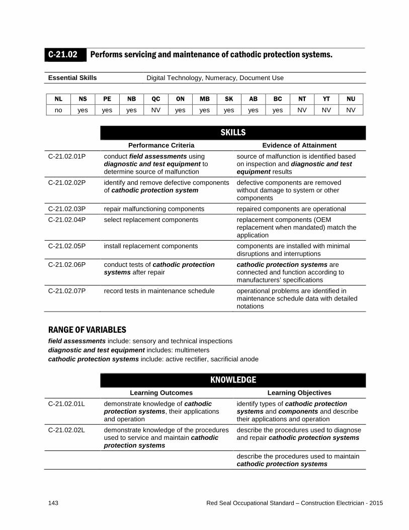
143 Red Seal Occupational Standard – Construction Electrician - 2015
C-21.02 Performs servicing and maintenance of cathodic protection systems. Essential Skills Digital Technology, Numeracy, Document Use
NL NS PE NB QC ON MB SK AB BC NT YT NU
no yes yes yes NV yes yes yes yes yes NV NV NV SKILLS
Performance Criteria Evidence of Attainment C-21.02.01P conduct field assessments using
diagnostic and test equipment to determine source of malfunction
source of malfunction is identified based on inspection and diagnostic and test equipment results
C-21.02.02P identify and remove defective components of cathodic protection system
defective components are removed without damage to system or other components
C-21.02.03P repair malfunctioning components repaired components are operational C-21.02.04P select replacement components replacement components (OEM
replacement when mandated) match the application
C-21.02.05P install replacement components components are installed with minimal disruptions and interruptions
C-21.02.06P conduct tests of cathodic protection systems after repair
cathodic protection systems are connected and function according to manufacturers’ specifications
C-21.02.07P record tests in maintenance schedule operational problems are identified in maintenance schedule data with detailed notations
RANGE OF VARIABLES field assessments include: sensory and technical inspections diagnostic and test equipment includes: multimeters cathodic protection systems include: active rectifier, sacrificial anode KNOWLEDGE
Learning Outcomes Learning Objectives C-21.02.01L demonstrate knowledge of cathodic
protection systems, their applications and operation
identify types of cathodic protection systems and components and describe their applications and operation
C-21.02.02L demonstrate knowledge of the procedures used to service and maintain cathodic protection systems
describe the procedures used to diagnose and repair cathodic protection systems
describe the procedures used to maintain cathodic protection systems
144 Red Seal Occupational Standard – Construction Electrician - 2015
RANGE OF VARIABLES cathodic protection systems include: active rectifier, sacrificial anode cathodic protection system components include: rectifier, insulation kits, cabling, breaker, anode connection cable, remote reference points, tap settings in the rectifier enclosure

145 Red Seal Occupational Standard – Construction Electrician - 2015
MAJOR WORK ACTIVITY D
INSTALLS, SERVICES AND MAINTAINS MOTORS AND CONTROL SYSTEMS Task D-22 Installs, services and maintains motor starters and controls. TASK DESCRIPTOR All electrical motors need a method to be started and controlled. These controls can be as simple as a single switch, or as complex as a starter assembly. Construction electricians install, service and maintain these starters and controls in the motor circuits. For the purpose of this standard, installation includes both new installations and upgrading of systems by removing and replacing components. Construction electricians service motor starters and controls by troubleshooting, diagnosing faults, and repairing them. They also perform maintenance to ensure motor starters and controls are in good operating condition. INDUSTRY EXPECTED PERFORMANCE The task must be performed according to the applicable jurisdictional codes and standards. All health and safety standards must be respected. Work should be done efficiently and at a high quality without material waste or harm to the environment. All requirements of the manufacturer, client specifications and the AHJ must be met. At a journeyperson level of performance, all tasks must be done with minimal direction and supervision.
D-22.01 Installs motor starters. Essential Skills Thinking Skills, Document Use, Numeracy
NL NS PE NB QC ON MB SK AB BC NT YT NU
yes yes yes yes NV yes yes yes yes yes NV NV NV SKILLS
Performance Criteria Evidence of Attainment D-22.01.01P determine type of motor starter for
specific application motor starter is selected and sized according to the application and according to drawings, specifications and CEC requirements
D-22.01.02P determine size and function of motor starter
size and function are determined according to motor manufacturers’ nameplate data

146 Red Seal Occupational Standard – Construction Electrician - 2015
D-22.01.03P calculate conductor requirements conductor type and size match the application and CEC requirements
D-22.01.04P position, mount and assemble starter assembly
starter assembly is placed in locations according to electrical drawings and job and client requirements
D-22.01.05P terminate conductors conductors and cables are terminated leaving no excessive bare conductor or loose strands and are functional according to the application
D-22.01.06P set up and adjust motor starters overloads are sized for the application and adjusted to provide maximum motor protection
D-22.01.07P interconnect starter with peripheral devices
interconnections are completed and equipment functions as intended
D-22.01.08P conduct tests of motor starter after installation and record results
motor starter is connected and functions according to manufacturers’ and client specifications
D-22.01.09P remove existing equipment when replacing and update documentation
equipment is removed with minimal impact to the environment and drawings reflect operational changes
RANGE OF VARIABLES motor starters include: starters for AC/DC motors, single phase, 3-phase AC, line voltage starters, soft starters, reduced-voltage starters manufacturers’ nameplate data includes: size of motor, full load amps (FLA), full load current (FLC), service factor, voltage starter assembly includes: fittings, enclosures, raceways, control transformers, overcurrent protection, overload protection, terminations peripheral devices include: start/stop stations, emergency stop stations, limit switches KNOWLEDGE
Learning Outcomes Learning Objectives D-22.01.01L demonstrate knowledge of motor
starters and their applications interpret information pertaining to motor starters found on motor nameplate, drawings and specifications
describe motor starters and their applications
interpret codes and regulations pertaining to motor starters
D-22.01.02L demonstrate knowledge of procedures used to install and connect motor starters
describe the procedures used to install motor starters, their components and accessories
describe the procedures used to connect motor starters, their components and accessories
identify enclosures and wiring methods based on application

147 Red Seal Occupational Standard – Construction Electrician - 2015
RANGE OF VARIABLES motor starters include: starters for AC/DC motors, single phase, 3-phase AC, line voltage starters, soft starters, reduced-voltage starters
D-22.02 Performs servicing and maintenance of motor starters. Essential Skills Oral Communication, Digital Technology, Writing
NL NS PE NB QC ON MB SK AB BC NT YT NU
yes yes yes yes NV yes yes yes yes yes NV NV NV SKILLS
Performance Criteria Evidence of Attainment D-22.02.01P obtain detailed description of operation
and malfunction of motor starters required information about equipment operation is gathered from end user
D-22.02.02P conduct field assessments using diagnostic and test equipment to determine source of malfunction
source of malfunction is identified based on diagnostic equipment results
D-22.02.03P identify and remove defective components of motor starters
defective component is removed without damage to system or other components
D-22.02.04P repair malfunctioning components repaired components are operational D-22.02.05P select replacement components replacement components (OEM
replacement when mandated) match the application
D-22.02.06P install replacement components components are installed with minimal disruptions and interruptions
D-22.02.07P conduct tests of motor starters after repair starter assembly is connected and functions according to manufacturers’ and client specifications
D-22.02.08P clean, lubricate and adjust components motor starter components are restored to optimal conditions
D-22.02.09P record tests in maintenance schedule operational problems are identified in maintenance schedule data with detailed notations
D-22.02.10P compare and analyze maintenance test results
maintenance is performed when required based on analysis of test results and comparison with specifications
RANGE OF VARIABLES adjust includes: re-torquing of terminations, overload settings, timing settings component conditions include: contact pressure, carbon build-up, pitting on contacts field assessments include: sensory and technical inspections diagnostic and test equipment include: multimeters, thermographic imaging devices, ammeters
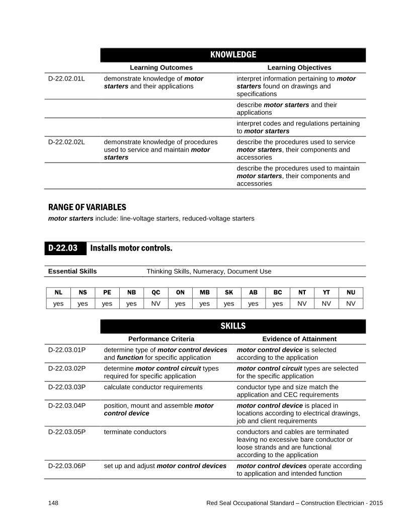
148 Red Seal Occupational Standard – Construction Electrician - 2015
KNOWLEDGE Learning Outcomes Learning Objectives
D-22.02.01L demonstrate knowledge of motor starters and their applications
interpret information pertaining to motor starters found on drawings and specifications
describe motor starters and their applications
interpret codes and regulations pertaining to motor starters
D-22.02.02L demonstrate knowledge of procedures used to service and maintain motor starters
describe the procedures used to service motor starters, their components and accessories
describe the procedures used to maintain motor starters, their components and accessories
RANGE OF VARIABLES motor starters include: line-voltage starters, reduced-voltage starters
D-22.03 Installs motor controls. Essential Skills Thinking Skills, Numeracy, Document Use
NL NS PE NB QC ON MB SK AB BC NT YT NU
yes yes yes yes NV yes yes yes yes yes NV NV NV SKILLS
Performance Criteria Evidence of Attainment D-22.03.01P determine type of motor control devices
and function for specific application motor control device is selected according to the application
D-22.03.02P determine motor control circuit types required for specific application
motor control circuit types are selected for the specific application
D-22.03.03P calculate conductor requirements conductor type and size match the application and CEC requirements
D-22.03.04P position, mount and assemble motor control device
motor control device is placed in locations according to electrical drawings, job and client requirements
D-22.03.05P terminate conductors conductors and cables are terminated leaving no excessive bare conductor or loose strands and are functional according to the application
D-22.03.06P set up and adjust motor control devices motor control devices operate according to application and intended function

149 Red Seal Occupational Standard – Construction Electrician - 2015
D-22.03.07P interconnect motor control devices with peripheral devices
interconnections are completed and equipment functions as intended
D-22.03.08P interconnect motor control devices with overload protection
interconnections are completed and equipment functions as intended
D-22.03.09P conduct tests of motor control devices after installation and record results
motor control devices are connected and function according to manufacturers’ and client specifications
D-22.03.10P remove existing equipment when replacing and update documentation
equipment is removed with minimal impact to the environment and drawings reflect operational changes
RANGE OF VARIABLES motor control devices include: flow switches, push buttons, relays, limit switches, proximity switches, pressure switches, level switches circuit functions include: starting and stopping, speed control, forward/reverse, sequencing, jogging, quick stop (plugging), multiple location control, time function motor control circuits include: low-voltage release (two-wire control), low-voltage protection (three-wire control) peripheral devices include: indicating lights, audible devices KNOWLEDGE
Learning Outcomes Learning Objectives D-22.03.01L demonstrate knowledge of motor control
devices and their applications interpret information pertaining to motor control devices found on drawings and specifications
describe motor control devices and their applications
interpret codes and regulations pertaining to motor control devices
D-22.03.02L demonstrate knowledge of motor control circuits, their characteristics and applications
interpret codes and regulations pertaining to motor control circuits
identify circuit types and describe their characteristics and applications
describe circuit functional features of common hard wired motor control circuits
identify the methods used to determine the number of conductors required between controls and controller locations
identify protection devices for motor control circuits and describe characteristics and applications

150 Red Seal Occupational Standard – Construction Electrician - 2015
RANGE OF VARIABLES motor control devices include: flow switches, push buttons, relays, limit switches, proximity switches, pressure switches, level switches motor control circuits include: low-voltage release (two-wire control), low-voltage protection (three-wire control) circuit functional features include: starting and stopping, forward/reverse, sequencing, jogging, quick stop (plugging), multiple location control, time function protection devices for control circuits include: overcurrent, overheating, phase loss, phase reversal
D-22.04 Performs servicing and maintenance of motor controls. Essential Skills Oral Communication, Digital Technology, Writing
NL NS PE NB QC ON MB SK AB BC NT YT NU
yes yes yes yes NV yes yes yes yes yes NV NV NV SKILLS
Performance Criteria Evidence of Attainment D-22.04.01P obtain detailed description of operation
and malfunction of motor controls required information about equipment operation is gathered from end user
D-22.04.02P conduct field assessments using diagnostic and test equipment to determine source of malfunction
source of malfunction is identified based on diagnostic and test equipment results
D-22.04.03P identify and remove defective components of motor controls
defective component are removed without damage to system or other components
D-22.04.04P select replacement components replacement components are selected according to application
D-22.04.05P install replacement components components are installed with minimal disruptions and interruptions
D-22.04.06P conduct tests of motor controls after repair control assembly is connected and functions according to manufacturers’ and client specifications
D-22.04.07P clean, lubricate and adjust components motor control devices are restored to optimal conditions
D-22.04.08P record tests in maintenance schedule operational problems are identified in maintenance schedule data with detailed notations
D-22.04.09P compare and analyze maintenance test results
maintenance is performed when required based on analysis of test results and comparison with specifications

151 Red Seal Occupational Standard – Construction Electrician - 2015
RANGE OF VARIABLES field assessments include: sensory and technical inspections diagnostic and test equipment include: multimeters, thermographic imaging devices, ammeters adjustments include: re-torquing of terminations, calibration of components conditions include: carbon or dust build-up, pitting on contacts, worn or dirty contacts KNOWLEDGE
Learning Outcomes Learning Objectives D-22.04.01L demonstrate knowledge of motor control
devices and their applications interpret information pertaining to motor control devices found on drawings and specifications
describe motor control devices and their applications
interpret codes and regulations pertaining to motor control devices
D-22.04.02L demonstrate knowledge of procedures used to service and maintain motor control devices
describe the procedures used to service motor control devices and their components
describe the procedures used to maintain motor control devices and their components
RANGE OF VARIABLES motor control devices include: flow switches, push buttons, relays, limit switches, pressure switches, level switches, motion sensors
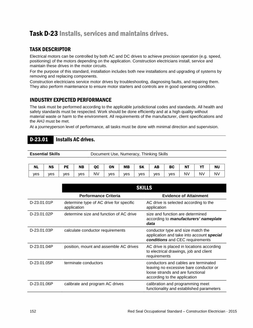
152 Red Seal Occupational Standard – Construction Electrician - 2015
Task D-23 Installs, services and maintains drives. TASK DESCRIPTOR Electrical motors can be controlled by both AC and DC drives to achieve precision operation (e.g. speed, positioning) of the motors depending on the application. Construction electricians install, service and maintain these drives in the motor circuits. For the purpose of this standard, installation includes both new installations and upgrading of systems by removing and replacing components. Construction electricians service motor drives by troubleshooting, diagnosing faults, and repairing them. They also perform maintenance to ensure motor starters and controls are in good operating condition. INDUSTRY EXPECTED PERFORMANCE The task must be performed according to the applicable jurisdictional codes and standards. All health and safety standards must be respected. Work should be done efficiently and at a high quality without material waste or harm to the environment. All requirements of the manufacturer, client specifications and the AHJ must be met. At a journeyperson level of performance, all tasks must be done with minimal direction and supervision.
D-23.01 Installs AC drives. Essential Skills Document Use, Numeracy, Thinking Skills
NL NS PE NB QC ON MB SK AB BC NT YT NU
yes yes yes yes NV yes yes yes yes yes NV NV NV SKILLS
Performance Criteria Evidence of Attainment D-23.01.01P determine type of AC drive for specific
application AC drive is selected according to the application
D-23.01.02P determine size and function of AC drive size and function are determined according to manufacturers’ nameplate data
D-23.01.03P calculate conductor requirements conductor type and size match the application and take into account special conditions and CEC requirements
D-23.01.04P position, mount and assemble AC drives AC drive is placed in locations according to electrical drawings, job and client requirements
D-23.01.05P terminate conductors conductors and cables are terminated leaving no excessive bare conductor or loose strands and are functional according to the application
D-23.01.06P calibrate and program AC drives calibration and programming meet functionality and established parameters

153 Red Seal Occupational Standard – Construction Electrician - 2015
D-23.01.07P interconnect AC drives with peripheral devices with required cables, raceways and conductors
interconnections are completed and equipment functions as intended
D-23.01.08P conduct tests of AC drive after installation and record results
AC drive is connected and functions according to manufacturers’ and client specifications
D-23.01.09P remove existing AC drives when replacing and update documentation
AC drive is removed with minimal impact to the environment and drawings reflect operational changes
RANGE OF VARIABLES manufacturers’ nameplate data includes: size of motor, full load current (FLC), inverter duty rated, voltage special conditions that affect conductor requirements include: shielding requirements, length of cable, type of VFD rated cable, reactor use, equipment bonding peripheral devices include: start/stop stations, emergency stop stations, speed control, sensing devices, encoders, tachometers, limit switches KNOWLEDGE
Learning Outcomes Learning Objectives D-23.01.01L demonstrate knowledge of types of AC
drives, their applications and operation identify types of AC drives and describe their characteristics, applications and operation
identify AC drive components and accessories and describe their characteristics, applications and operation
interpret information pertaining to AC drives found on drawings and specifications
interpret codes and regulations pertaining to AC drives
explain operating principles of AC drives and their impact on motor performance
D-23.01.02L demonstrate knowledge of procedures used to install and connect AC drives
identify the considerations and requirements for selecting AC drives, their components and accessories
describe the procedures used to install AC drives, their components and accessories
describe the procedures used to connect AC drives, their components and accessories
describe the procedures used to adjust AC drives, their components and accessories

154 Red Seal Occupational Standard – Construction Electrician - 2015
RANGE OF VARIABLES AC drive components include: rectifiers, electro-magnetic compatibility (EMC) filters, DC circuits, inverters
D-23.02 Performs servicing and maintenance of AC drives. Essential Skills Oral Communication, Digital Technology, Document Use
NL NS PE NB QC ON MB SK AB BC NT YT NU
yes yes yes yes NV yes yes yes yes yes NV NV NV SKILLS
Performance Criteria Evidence of Attainment D-23.02.01P obtain detailed description of operation
and malfunction of AC drives required information about equipment operation is gathered from end user
D-23.02.02P conduct field assessments using diagnostic and test equipment to determine source of malfunction
source of malfunction is identified based on diagnostic equipment results
D-23.02.03P identify and remove defective components of AC drives
defective components are removed without damage to system or other components
D-23.02.04P repair malfunctioning components repaired components are operational D-23.02.05P select replacement components replacement components (OEM
replacement when mandated) match the application
D-23.02.06P install replacement components components are installed with minimal disruptions and interruptions
D-23.02.07P conduct tests of AC drives after repair AC drive assembly is connected and functions according to manufacturers’ and client specifications
D-23.02.08P clean, lubricate and adjust components AC drive components are restored to optimal conditions
D-23.02.09P record tests in maintenance schedule operational problems are identified in maintenance schedule data with detailed notations
D-23.02.10P compare and analyze maintenance test results
maintenance is performed when required based on analysis of test results and comparison with specifications

155 Red Seal Occupational Standard – Construction Electrician - 2015
RANGE OF VARIABLES cleaning, lubricating and adjustment procedures include: re-torquing of terminations, cleaning filters and cooling fans, checking door seals cleaning, lubricating and adjustment procedures include: re-torquing of terminations, cleaning filters and cooling fans, checking door seals diagnostic and test equipment include: multimeters, thermographic imaging devices, ammeters, oscilloscopes tests include: resistance tests of power semiconductors KNOWLEDGE
Learning Outcomes Learning Objectives D-23.02.01L demonstrate knowledge of types of AC
drives, their applications and operation identify types of AC drives and describe their characteristics, applications and operation
identify AC drive components and accessories and describe their characteristics, applications and operation
interpret information pertaining to AC drives found on drawings and specifications
interpret codes and regulations pertaining to AC drives
explain operating principles of AC drives and their impact on motor performance
D-23.02.02L demonstrate knowledge of procedures used to service and maintain AC drives
describe the procedures used to service and maintain AC drives, their components and accessories
RANGE OF VARIABLES AC drive components include: rectifiers, EMC filters, DC circuits, inverters

156 Red Seal Occupational Standard – Construction Electrician - 2015
D-23.03 Installs DC drives. Essential Skills Document Use, Numeracy, Thinking Skills
NL NS PE NB QC ON MB SK AB BC NT YT NU
no yes no yes NV yes yes yes yes yes NV NV NV SKILLS
Performance Criteria Evidence of Attainment D-23.03.01P determine type of DC drive for specific
application DC drive is selected and sized according to the application
D-23.03.02P determine size and function of DC drive size and function are determined according to manufacturers’ nameplate data
D-23.03.03P calculate conductor requirements conductor type and size match the application and take into account special conditions and CEC requirements
D-23.03.04P position, mount and assemble DC drives DC drive is placed in locations according to electrical drawings, job and client requirements
D-23.03.05P terminate conductors conductors and cables are terminated leaving no excessive bare conductor or loose strands and are functional according to the application
D-23.03.06P calibrate and program DC drives calibration and programming meets functionality and established parameters
D-23.03.07P interconnect DC drives with peripheral devices with required cables, raceways and conductors
interconnections are completed and equipment functions as intended
D-23.03.08P conduct tests of DC drive after installation and record results
DC drive is connected and functions according to manufacturers’ and client specifications
D-23.03.09P remove existing DC drives when replacing and update documentation
DC drive is removed with minimal impact to the environment and drawings reflect operational changes
RANGE OF VARIABLES manufacturers’ nameplate data includes: size of motor, FLA, voltage special conditions that affect feeder requirements include: shielding requirements, length of cable, line reactor peripheral devices include: start/stop stations, emergency stop stations, speed control, sensing devices, encoders, tachometers, limit switches
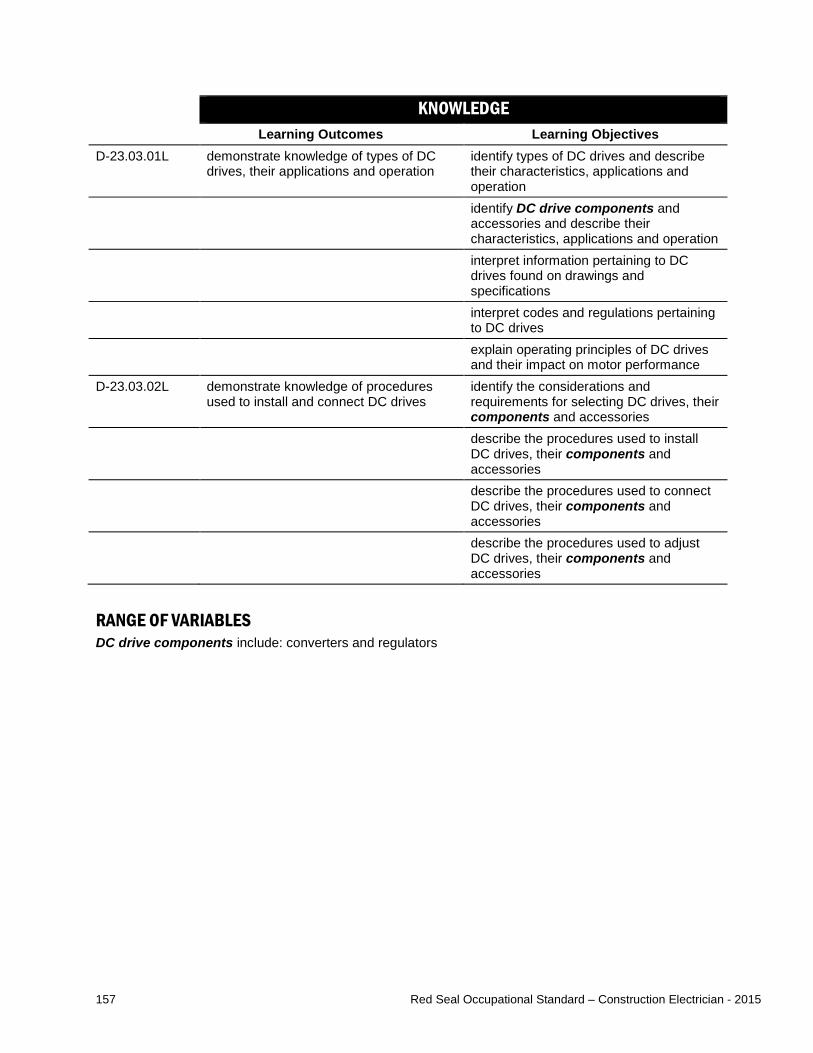
157 Red Seal Occupational Standard – Construction Electrician - 2015
KNOWLEDGE Learning Outcomes Learning Objectives
D-23.03.01L demonstrate knowledge of types of DC drives, their applications and operation
identify types of DC drives and describe their characteristics, applications and operation
identify DC drive components and accessories and describe their characteristics, applications and operation
interpret information pertaining to DC drives found on drawings and specifications
interpret codes and regulations pertaining to DC drives
explain operating principles of DC drives and their impact on motor performance
D-23.03.02L demonstrate knowledge of procedures used to install and connect DC drives
identify the considerations and requirements for selecting DC drives, their components and accessories
describe the procedures used to install DC drives, their components and accessories
describe the procedures used to connect DC drives, their components and accessories
describe the procedures used to adjust DC drives, their components and accessories
RANGE OF VARIABLES DC drive components include: converters and regulators

158 Red Seal Occupational Standard – Construction Electrician - 2015
D-23.04 Performs servicing and maintenance of DC drives. Essential Skills Oral Communication, Digital Technology, Writing
NL NS PE NB QC ON MB SK AB BC NT YT NU
no yes no yes NV yes yes yes yes yes NV NV NV SKILLS
Performance Criteria Evidence of Attainment D-23.04.01P obtain detailed description of operation
and malfunction of DC drives required information about equipment operation is gathered from end user
D-23.04.02P conduct field assessments using diagnostic and test equipment to determine source of malfunction
source of malfunction is identified based on diagnostic equipment results
D-23.04.03P identify and remove defective components of DC drives
defective components are removed without damage to system or other components
D-23.04.04P repair malfunctioning components repaired components are operational D-23.04.05P select replacement components replacement components (OEM
replacement when mandated) match the application
D-23.04.06P install replacement components components are installed with minimal disruptions and interruptions
D-23.04.07P conduct tests of DC drives after repair DC drive assembly is connected and functions according to manufacturers’ and client specifications
D-23.04.08P clean, lubricate and adjust components DC drive components are restored to optimal conditions
D-23.04.09P record tests in maintenance schedule operational problems are identified in maintenance schedule data
D-23.04.10P compare and analyze maintenance test results
maintenance is performed when required based on analysis of test results and comparison with specifications
RANGE OF VARIABLES cleaning, lubrication and adjustment procedures include: re-torquing of terminations, cleaning filters and cooling fans, checking door seals field assessments include: sensory and technical inspections diagnostic and test equipment include: multimeters, thermographic imaging devices, ammeters, oscilloscopes

159 Red Seal Occupational Standard – Construction Electrician - 2015
KNOWLEDGE Learning Outcomes Learning Objectives
D-23.04.01L demonstrate knowledge of types of DC drives, their applications and operation
identify types of DC drives and describe their characteristics, applications and operation
identify DC drive components and accessories and describe their characteristics, applications and operation
interpret information pertaining to DC drives found on drawings and specifications
interpret codes and regulations pertaining to DC drives
explain operating principles of DC drives and their impact on motor performance
D-23.04.02L demonstrate knowledge of procedures used to service and maintain DC drives
describe the procedures used to service and maintain DC drives, their components and accessories
RANGE OF VARIABLES DC drive components include: converters and regulators

160 Red Seal Occupational Standard – Construction Electrician - 2015
Task D-24 Installs, services and maintains motors. TASK DESCRIPTOR Motors are used to convert electrical energy to mechanical energy. Construction electricians install, service and maintain single-phase, three-phase and DC motors. For the purpose of this standard, installation includes both new installations and upgrading of systems by removing and replacing components. Construction electricians service motors by troubleshooting, diagnosing faults, and repairing them. They also perform maintenance to ensure motors are in good operating condition. INDUSTRY EXPECTED PERFORMANCE The task must be performed according to the applicable jurisdictional codes and standards. All health and safety standards must be respected. Work should be done efficiently and at a high quality without material waste or harm to the environment. All requirements of the manufacturer, client specifications and the AHJ must be met. At a journeyperson level of performance, all tasks must be done with minimal direction and supervision.
D-24.01 Installs single-phase motors. Essential Skills Document Use, Thinking Skills, Numeracy
NL NS PE NB QC ON MB SK AB BC NT YT NU
yes yes yes yes NV yes yes yes yes yes NV NV NV SKILLS
Performance Criteria Evidence of Attainment D-24.01.01P determine type of single-phase motor
required type of single-phase motor meets criteria for operation
D-24.01.02P calculate conductor requirements conductor type and size match the application and CEC requirements
D-24.01.03P determine and install overload and overcurrent devices based on requirements
overload and overcurrent devices are installed such that the motor is protected
D-24.01.04P position and mount single-phase motor single-phase motor is mounted according to the application
D-24.01.05P connect motor leads motor leads are connected according to the application
D-24.01.06P conduct tests of single-phase motor after installation and record results
single-phase motor is connected and functions according to manufacturers’ and client specifications
D-24.01.07P remove existing single-phase motor when replacing and update documentation
single-phase motor is removed with minimal impact to the environment and drawings reflect operational changes

161 Red Seal Occupational Standard – Construction Electrician - 2015
RANGE OF VARIABLES single-phase motors include: hermetically sealed, dual capacitor, reluctance, capacitor start/induction run, split phase, universal, resistance split phase, permanent split capacitor, shaded pole criteria for operation of single-phase motors include: voltage availability, motor function, rotation, location KNOWLEDGE
Learning Outcomes Learning Objectives D-24.01.01L demonstrate knowledge of single-phase
motors, their applications and operation identify types of single-phase motors and describe their characteristics
identify single-phase motor components and accessories and describe their applications
interpret codes and regulations pertaining to single-phase motors
interpret information pertaining to single-phase motors found on drawings and specifications
explain the construction and operating principles of single-phase motors
interpret information contained on single-phase motor nameplates
D-24.01.02L demonstrate knowledge of procedures used to install and connect single-phase motors
describe procedures used to install single-phase motors
describe procedures used to connect single-phase motors
identify coupling methods for single-phase motors and describe their characteristics and applications
identify the considerations and requirements for selecting single-phase motors and their components
RANGE OF VARIABLES single-phase motors include: hermetically sealed, dual capacitor, reluctance, capacitor start/induction run, split phase, universal, resistance split phase, permanent split capacitor, shaded pole coupling methods include: flexible couplings, fixed couplings, magnetic couplings, belts and chains

162 Red Seal Occupational Standard – Construction Electrician - 2015
D-24.02 Performs servicing and maintenance of single-phase motors. Essential Skills Oral Communication, Digital Technology, Document Use
NL NS PE NB QC ON MB SK AB BC NT YT NU
yes yes yes yes NV yes yes yes yes yes NV NV NV SKILLS
Performance Criteria Evidence of Attainment D-24.02.01P obtain detailed description of operation
and malfunction of single-phase motors required information about equipment operation is gathered from end user
D-24.02.02P conduct field assessments using diagnostic and test equipment to determine source of malfunction
source of malfunction is identified based on diagnostic and test equipment results
D-24.02.03P identify and remove defective components of single-phase motors
defective components are removed without damage to system or other components
D-24.02.04P select replacement components replacement components match the application
D-24.02.05P install replacement components components are installed with minimal disruptions and interruptions
D-24.02.06P conduct tests of single-phase motors after repair
single-phase motor assembly is connected and functions according to specifications to match the application
D-24.02.07P clean, lubricate and adjust components single-phase motor components are restored to optimal conditions
D-24.02.08P record tests in maintenance schedule operational problems are identified in maintenance schedule data
D-24.02.09P compare and analyze maintenance test results
maintenance is performed when required based on analysis of test results and specifications
RANGE OF VARIABLES cleaning, lubrication and adjustment procedures include: cleaning cooling fans, adjusting belt tensioners, lubricating bearings and bushings, cleaning switches field assessments include: sensory and technical inspections diagnostic and test equipment includes: multimeters, thermographic imaging devices, ammeters, insulation resistance testers tests include: vibration, insulation, current, rotation, alignment, baseline motor diagnostic test
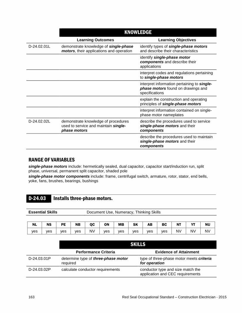
163 Red Seal Occupational Standard – Construction Electrician - 2015
KNOWLEDGE Learning Outcomes Learning Objectives
D-24.02.01L demonstrate knowledge of single-phase motors, their applications and operation
identify types of single-phase motors and describe their characteristics
identify single-phase motor components and describe their applications
interpret codes and regulations pertaining to single-phase motors
interpret information pertaining to single-phase motors found on drawings and specifications
explain the construction and operating principles of single-phase motors
interpret information contained on single-phase motor nameplates
D-24.02.02L demonstrate knowledge of procedures used to service and maintain single-phase motors
describe the procedures used to service single-phase motors and their components
describe the procedures used to maintain single-phase motors and their components
RANGE OF VARIABLES single-phase motors include: hermetically sealed, dual capacitor, capacitor start/induction run, split phase, universal, permanent split capacitor, shaded pole single-phase motor components include: frame, centrifugal switch, armature, rotor, stator, end bells, yoke, fans, brushes, bearings, bushings
D-24.03 Installs three-phase motors. Essential Skills Document Use, Numeracy, Thinking Skills
NL NS PE NB QC ON MB SK AB BC NT YT NU
yes yes yes yes NV yes yes yes yes yes NV NV NV SKILLS
Performance Criteria Evidence of Attainment D-24.03.01P determine type of three-phase motor
required type of three-phase motor meets criteria for operation
D-24.03.02P calculate conductor requirements conductor type and size match the application and CEC requirements

164 Red Seal Occupational Standard – Construction Electrician - 2015
D-24.03.03P determine and install overload and overcurrent devices based on requirements
overload and overcurrent devices are installed such that the motor is protected
D-24.03.04P determine and install motor protection devices
motor protection devices are installed such that motor is protected
D-24.03.05P position and mount three-phase motor three-phase motor is mounted according to the application
D-24.03.06P connect motor leads motor leads are connected according to the application
D-24.03.07P conduct tests of three-phase motors after installation and record results
three-phase motors are connected and function according to specifications to match the application
D-24.03.08P remove existing three-phase motors when replacing and update documentation
three-phase motors are removed with minimal impact to the environment and drawings reflect operational changes
RANGE OF VARIABLES three-phase motors include: squirrel cage induction, synchronous, wound rotor induction criteria for operation of three-phase motors includes: voltage availability, motor function, rotation, location motor protection devices include: phase loss/reversal protection, high temperature sensors tests include: vibration, insulation, current, rotation, alignment, baseline motor diagnostic test KNOWLEDGE
Learning Outcomes Learning Objectives D-24.03.01L demonstrate knowledge of three-phase
motors, their applications and procedures for use
identify types of three-phase motors and describe their characteristics
identify three-phase motor components and describe their applications
interpret codes and regulations pertaining to three-phase motors
interpret information pertaining to three-phase motors found on drawings and specifications
explain the construction and operating principles of three-phase motors
interpret information contained on three-phase motor nameplates
D-24.03.02L demonstrate knowledge of procedures used to install and connect three-phase motors
describe procedures used to install three-phase motors
describe procedures used to connect three-phase motors

165 Red Seal Occupational Standard – Construction Electrician - 2015
identify coupling methods for three-phase motors and describe their characteristics and applications
identify the considerations and requirements for selecting three-phase motors and their components
RANGE OF VARIABLES three-phase motors include: squirrel cage induction, synchronous, wound rotor induction coupling methods include: flexible couplings, fixed couplings, magnetic couplings, belts and chains
D-24.04 Performs servicing and maintenance of three-phase motors. Essential Skills Oral Communication, Digital Technology, Writing
NL NS PE NB QC ON MB SK AB BC NT YT NU
yes yes yes yes NV yes yes yes yes yes NV NV NV SKILLS
Performance Criteria Evidence of Attainment D-24.04.01P obtain detailed description of operation
and malfunction of three-phase motors required information about equipment operation is gathered from end user
D-24.04.02P conduct field assessments using diagnostic and test equipment to determine source of malfunction
source of malfunction is identified based on diagnostic and test equipment results
D-24.04.03P identify and remove defective components of three-phase motors
defective components are removed without damage to system or other components
D-24.04.04P select replacement components replacement components match the application
D-24.04.05P install replacement components components are installed with minimal disruptions and interruptions
D-24.04.06P conduct tests of three-phase motors after repair
three-phase motor assembly is connected and functions according to specifications to match the application
D-24.04.07P clean, lubricate and adjust components three-phase motor components are restored to optimal conditions
D-24.04.08P record tests in maintenance schedule operational problems are identified in maintenance schedule data
D-24.04.09P compare and analyze maintenance test results
maintenance is performed when required based on analysis of test results and specifications
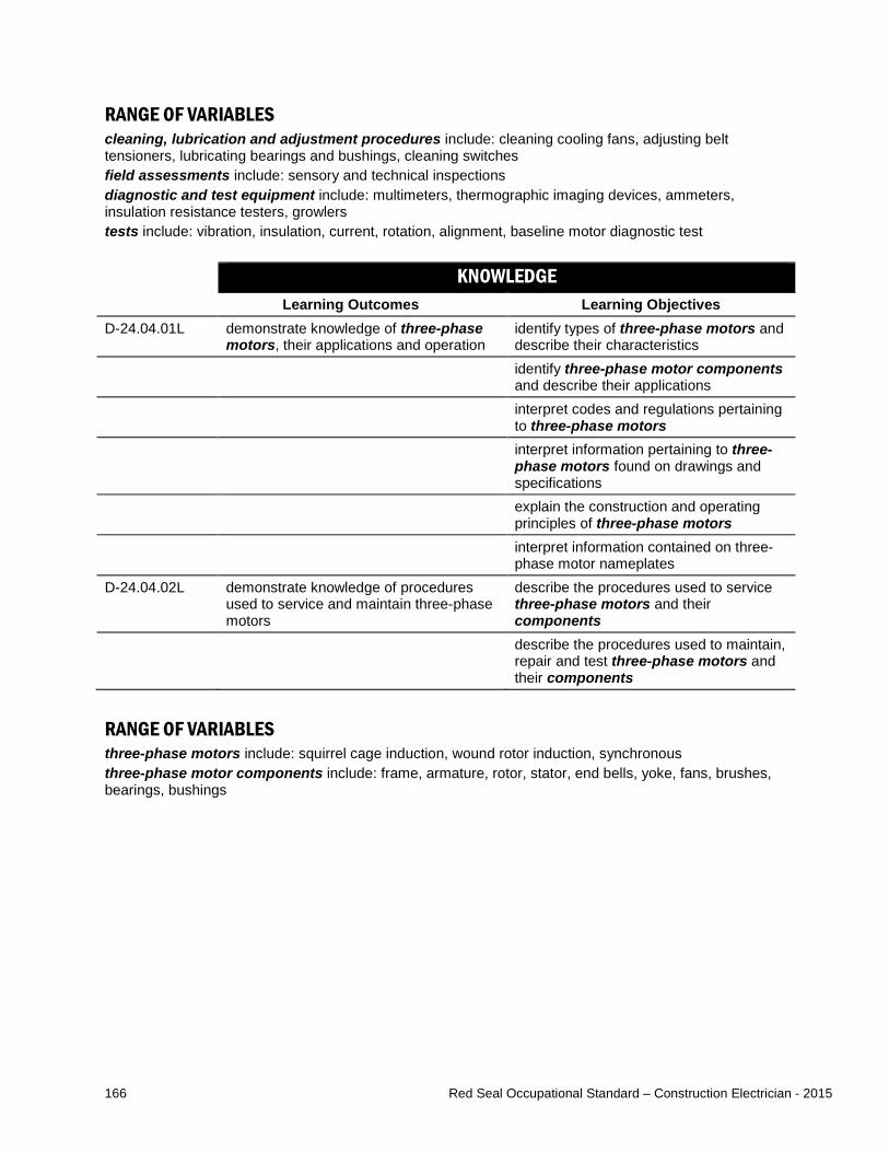
166 Red Seal Occupational Standard – Construction Electrician - 2015
RANGE OF VARIABLES cleaning, lubrication and adjustment procedures include: cleaning cooling fans, adjusting belt tensioners, lubricating bearings and bushings, cleaning switches field assessments include: sensory and technical inspections diagnostic and test equipment include: multimeters, thermographic imaging devices, ammeters, insulation resistance testers, growlers tests include: vibration, insulation, current, rotation, alignment, baseline motor diagnostic test KNOWLEDGE
Learning Outcomes Learning Objectives D-24.04.01L demonstrate knowledge of three-phase
motors, their applications and operation identify types of three-phase motors and describe their characteristics
identify three-phase motor components and describe their applications
interpret codes and regulations pertaining to three-phase motors
interpret information pertaining to three-phase motors found on drawings and specifications
explain the construction and operating principles of three-phase motors
interpret information contained on three-phase motor nameplates
D-24.04.02L demonstrate knowledge of procedures used to service and maintain three-phase motors
describe the procedures used to service three-phase motors and their components
describe the procedures used to maintain, repair and test three-phase motors and their components
RANGE OF VARIABLES three-phase motors include: squirrel cage induction, wound rotor induction, synchronous three-phase motor components include: frame, armature, rotor, stator, end bells, yoke, fans, brushes, bearings, bushings

167 Red Seal Occupational Standard – Construction Electrician - 2015
D-24.05 Installs DC motors. Essential Skills Numeracy, Digital Technology, Document Use
NL NS PE NB QC ON MB SK AB BC NT YT NU
yes yes yes yes NV yes yes yes yes yes NV NV NV SKILLS
Performance Criteria Evidence of Attainment D-24.05.01P determine type of DC motor required DC motor to be installed meets criteria
for operation D-24.05.02P calculate conductor requirements conductor type and size match the
application and CEC requirements D-24.05.03P determine and install overload and
overcurrent devices based on requirements
overload and overcurrent devices are installed such that the motor is protected
D-24.05.04P position and mount DC motor DC motor is mounted according to the application
D-24.05.05P connect motor leads motor leads are connected according to the application
D-24.05.06P conduct tests of DC motor after installation and record results
DC motor is connected and functions according to manufacturers’ and client specifications
D-24.05.07P remove existing DC motors when replacing and update documentation
DC motors are removed with minimal impact to the environment and drawings reflect operational changes
RANGE OF VARIABLES criteria for operation of DC motors include: voltage availability, motor function, rotation, location KNOWLEDGE
Learning Outcomes Learning Objectives D-24.05.01L demonstrate knowledge of DC motors,
their applications and procedures for use identify types of DC motors and describe their characteristics and applications
identify DC motor components and describe their characteristics and applications
interpret codes and regulations pertaining to DC motors
interpret information pertaining to DC motors found on drawings and specifications
explain the construction and operating principles of DC motors

168 Red Seal Occupational Standard – Construction Electrician - 2015
interpret information contained on DC motor nameplates
D-24.05.02L demonstrate knowledge of procedures used to install and connect DC motors
identify considerations and requirements for selecting DC motors and controls, and their components
describe the procedures used to install DC motors and controls, and their components
describe the procedures used to connect DC motors and controls and their components
RANGE OF VARIABLES DC motors include: self-excited, separately excited, series, shunt, compound DC motor components include: frame, armature, rotor, stator, commutator, end bells, yoke, fans, brushes, bearings, bushings
D-24.06 Performs servicing and maintenance of DC motors. Essential Skills Oral Communication, Digital Technology, Writing
NL NS PE NB QC ON MB SK AB BC NT YT NU
yes yes yes yes NV yes yes yes yes yes NV NV NV SKILLS
Performance Criteria Evidence of Attainment D-24.06.01P obtain detailed description of operation
and malfunction of DC motors required information about equipment operation is gathered from end user
D-24.06.02P conduct field assessments using diagnostic and test equipment to determine source of malfunction
source of malfunction is identified based on diagnostic equipment results
D-24.06.03P identify and remove defective components of DC motors
defective components are removed without damage to system or other components
D-24.06.04P select replacement components replacement components (OEM replacement when mandated) are selected to match the application
D-24.06.05P install replacement components components are installed with minimal disruptions and interruptions
D-24.06.06P conduct tests of DC motors after repair DC motor assembly is connected and functions according to manufacturers’ and client specifications
D-24.06.07P clean, lubricate and adjust components DC motor components are restored to optimal conditions

169 Red Seal Occupational Standard – Construction Electrician - 2015
D-24.06.08P record tests in maintenance schedule operational problems are identified in maintenance schedule data
D-24.06.09P compare and analyze maintenance test results
maintenance is performed when required based on analysis of test results and specifications
RANGE OF VARIABLES cleaning, lubrication and adjustment procedures include: cleaning cooling fans, adjusting belt tensioners, lubricating bearings and bushings, and cleaning switches, cleaning and adjusting brushes, cleaning commutator segments field assessments include: sensory and technical inspections diagnostic and test equipment include: multimeters, thermographic imaging devices, ammeters, insulation resistance testers KNOWLEDGE
Learning Outcomes Learning Objectives D-24.06.01L demonstrate knowledge of DC motors,
their applications and procedures for use identify types of DC motors and describe their characteristics and applications
identify DC motor components and describe their characteristics and applications
interpret codes and regulations pertaining to DC motors
interpret information pertaining to DC motors found on drawings and specifications
explain the construction and operating principles of DC motors
interpret information contained on DC motor nameplates
D-24.06.02L demonstrate knowledge of procedures used to service and maintain DC motors
describe the procedures used to service DC motors and their components
describe the procedures used to maintain DC motors and their components
D-24.06.01L demonstrate knowledge of DC motors, their applications and procedures for use
identify types of DC motors and describe their characteristics and applications
RANGE OF VARIABLES DC motors include: self-excited, separately excited, series, shunt, compound DC motor components include: frame, armature, rotor, stator, commutator, end bells, yoke, fans, brushes, bearings, bushings
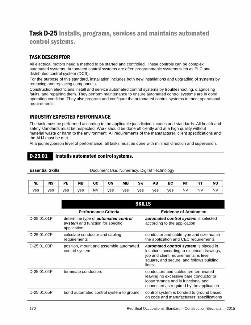
170 Red Seal Occupational Standard – Construction Electrician - 2015
Task D-25 Installs, programs, services and maintains automated control systems. TASK DESCRIPTOR All electrical motors need a method to be started and controlled. These controls can be complex automated systems. Automated control systems are often programmable systems such as PLC and distributed control system (DCS). For the purpose of this standard, installation includes both new installations and upgrading of systems by removing and replacing components. Construction electricians install and service automated control systems by troubleshooting, diagnosing faults, and repairing them. They perform maintenance to ensure automated control systems are in good operating condition. They also program and configure the automated control systems to meet operational requirements. INDUSTRY EXPECTED PERFORMANCE The task must be performed according to the applicable jurisdictional codes and standards. All health and safety standards must be respected. Work should be done efficiently and at a high quality without material waste or harm to the environment. All requirements of the manufacturer, client specifications and the AHJ must be met. At a journeyperson level of performance, all tasks must be done with minimal direction and supervision.
D-25.01 Installs automated control systems. Essential Skills Document Use, Numeracy, Digital Technology
NL NS PE NB QC ON MB SK AB BC NT YT NU
yes yes yes yes NV yes yes yes yes yes NV NV NV SKILLS
Performance Criteria Evidence of Attainment D-25.01.01P determine type of automated control
system and function for specific application
automated control system is selected according to the application
D-25.01.02P calculate conductor and cabling requirements
conductor and cable type and size match the application and CEC requirements
D-25.01.03P position, mount and assemble automated control system
automated control system is placed in locations according to electrical drawings, job and client requirements; is level, square, and secure, and follows building lines
D-25.01.04P terminate conductors conductors and cables are terminated leaving no excessive bare conductor or loose strands and is functional and connected as required by the application
D-25.01.05P bond automated control system to ground control system is bonded to ground based on code and manufacturers’ specifications

171 Red Seal Occupational Standard – Construction Electrician - 2015
D-25.01.06P set up and adjust automated control system
automated control system operates according to application and intended function
D-25.01.07P interconnect automated control system with peripheral devices
interconnections are completed and equipment functions as intended
D-25.01.08P conduct tests of automated control system after installation and record results
automated control system is connected and functions according to manufacturers’ and client specifications
D-25.01.09P remove existing equipment when replacing and update documentation
equipment is removed with minimal impact to the environment and drawings reflect operational changes
RANGE OF VARIABLES automated control systems include: PLC, Supervisory Control and Data Acquisition (SCADA) system, DCS peripheral devices of automated control systems may be analog or digital and include: input devices (flow switches, push buttons, limit switches, pressure switches, level switches), output devices (pilot lights, audible devices, relays) KNOWLEDGE
Learning Outcomes Learning Objectives D-25.01.01L demonstrate knowledge of automated
control systems, their applications and operation
identify types of automated control systems and describe their characteristics
identify automated control system components and describe their purpose and operation
interpret information pertaining to automated control systems found on drawings and specifications
interpret codes and regulations pertaining to automated control systems
identify sources of information pertaining to automated control system service, maintenance, configuration and programming
identify number and code systems and describe their applications
perform conversions between number systems
explain and interpret control circuit logic D-25.01.02L demonstrate knowledge of automated
control system data highway systems identify types of automated control system data highway systems and describe their characteristics, applications and operation

172 Red Seal Occupational Standard – Construction Electrician - 2015
identify automated control system data highway system components and describe their characteristics, applications and operation
identify methods used to communicate with automated control systems
identify basic instruction sets for ladder logic and describe their applications
D-25.01.03L demonstrate knowledge of procedures used to install and connect automated control systems and their components
describe the procedures used to install automated control systems and their components
describe the procedures used to connect automated control systems and their components
RANGE OF VARIABLES automated control systems include: PLC, SCADA system, DCS automated control system components include: hardware (power supply, central processing unit [CPU], input/output [I/O] system, programming terminals), software number systems include: binary, decimal, hexadecimal, octal code systems include: binary coded decimal (BCD), American Standard Code for Information Interchange (ASCII) control circuit logic includes: relay logic, AND, OR, NOT, NOR and MEMORY automated control system data highway systems include: Ethernet, Modbus, Profibus, BACnet, Fieldbus, DeviceNet methods used to communicate with automated control systems include handheld, computer, human machine interfacing (HMI) basic instruction sets for ladder logic include: examine if opened (XIO), examine if closed (XIC), output energized (OTE)
D-25.02 Performs servicing and maintenance of automated control systems. Essential Skills Oral Communication, Digital Technology, Numeracy
NL NS PE NB QC ON MB SK AB BC NT YT NU
yes yes yes yes NV yes yes yes yes yes NV NV NV SKILLS
Performance Criteria Evidence of Attainment D-25.02.01P obtain detailed description of operation
and malfunction of automated control systems
required information about equipment operation is gathered from end user and CPU diagnostics
D-25.02.02P conduct field assessments using diagnostic and test equipment to determine source of malfunction
source of malfunction is identified based on diagnostic and test equipment results, and sensory and technical observations

173 Red Seal Occupational Standard – Construction Electrician - 2015
D-25.02.03P identify and remove defective components of automated control systems
defective components are removed without damage to system or other components
D-25.02.04P repair malfunctioning components repaired components are operational D-25.02.05P select replacement components replacement components (OEM
replacement when mandated) match the application
D-25.02.06P install replacement components components are installed with minimal disruptions and interruptions
D-25.02.07P conduct tests of automated control systems after repair
automated control system is connected and functions according to manufacturers’ and client specifications
D-25.02.08P clean and adjust components automated control systems are restored to optimal conditions
D-25.02.09P complete backups and record tests in maintenance schedule
operational problems are identified in maintenance schedule data
D-25.02.10P compare and analyze maintenance test results
maintenance is performed when required based on analysis of test results and specifications
RANGE OF VARIABLES cleaning and adjustment procedures include: cleaning fans and filters, adjusting cabinets and door seals field assessments include: sensory and technical inspections diagnostic and test equipment includes: multimeters, thermographic imaging devices, ammeters, laptops KNOWLEDGE
Learning Outcomes Learning Objectives D-25.02.01L demonstrate knowledge of automated
control systems, their applications and operation
identify types of automated control systems and describe their characteristics, applications and operation
identify automated control system components and describe their purpose and operation
interpret information pertaining to automated control systems found on drawings and specifications
interpret codes and regulations pertaining to automated control systems
identify sources of information pertaining to automated control system service, maintenance, configuration and programming
identify number and code systems and describe their applications
perform conversions between number systems

174 Red Seal Occupational Standard – Construction Electrician - 2015
explain and interpret control circuit logic D-25.02.02L demonstrate knowledge of automated
control system data highway systems identify types of automated control system data highway systems and describe their characteristics, applications and operation
identify automated control system data highway system components and describe their characteristics, applications and operation
identify methods used to communicate with automated control systems
identify basic instruction sets for ladder logic and describe their applications
D-25.02.03L demonstrate knowledge of procedures for service and maintenance of automated control systems
describe the procedures used to service and maintain automated control systems and their components
RANGE OF VARIABLES automated control systems include: PLC, SCADA system, DCS automated control system components include: hardware (power supply, central processing unit [CPU], input/output [I/O] system, programming terminals), software number systems include: binary, decimal, hexadecimal, octal code systems include: BCD, ASCII control circuit logic includes: relay logic, AND, OR, NOT, NOR and MEMORY automated control system data highway systems include: Ethernet, Modbus, Profibus, BACnet, Fieldbus, DeviceNet methods used to communicate with automated control systems include: handheld, computer, HMI basic instruction sets for ladder logic include: XIO, XIC, OTE
D-25.03 Programs and configures automated control systems. Essential Skills Document Use, Reading, Digital Technology
NL NS PE NB QC ON MB SK AB BC NT YT NU
yes yes yes yes NV yes yes yes yes yes NV NV NV SKILLS
Performance Criteria Evidence of Attainment D-25.03.01P set inputs and outputs and create I/O
tables tables include all required parameters
D-25.03.02P set names for variables all variables are named according to client naming application
D-25.03.03P write and verify automated control program
automated control program operates according to specified logic
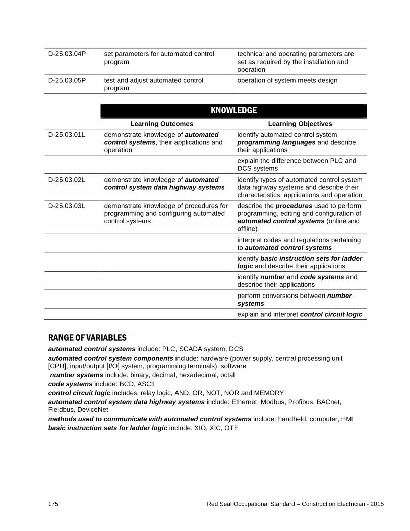
175 Red Seal Occupational Standard – Construction Electrician - 2015
D-25.03.04P set parameters for automated control program
technical and operating parameters are set as required by the installation and operation
D-25.03.05P test and adjust automated control program
operation of system meets design
KNOWLEDGE Learning Outcomes Learning Objectives
D-25.03.01L demonstrate knowledge of automated control systems, their applications and operation
identify automated control system programming languages and describe their applications
explain the difference between PLC and DCS systems
D-25.03.02L demonstrate knowledge of automated control system data highway systems
identify types of automated control system data highway systems and describe their characteristics, applications and operation
D-25.03.03L demonstrate knowledge of procedures for programming and configuring automated control systems
describe the procedures used to perform programming, editing and configuration of automated control systems (online and offline)
interpret codes and regulations pertaining to automated control systems
identify basic instruction sets for ladder logic and describe their applications
identify number and code systems and describe their applications
perform conversions between number systems
explain and interpret control circuit logic
RANGE OF VARIABLES automated control systems include: PLC, SCADA system, DCS automated control system components include: hardware (power supply, central processing unit [CPU], input/output [I/O] system, programming terminals), software number systems include: binary, decimal, hexadecimal, octal code systems include: BCD, ASCII control circuit logic includes: relay logic, AND, OR, NOT, NOR and MEMORY automated control system data highway systems include: Ethernet, Modbus, Profibus, BACnet, Fieldbus, DeviceNet methods used to communicate with automated control systems include: handheld, computer, HMI basic instruction sets for ladder logic include: XIO, XIC, OTE

176 Red Seal Occupational Standard – Construction Electrician - 2015
MAJOR WORK ACTIVITY E INSTALLS, SERVICES AND MAINTAINS SIGNALLING AND COMMUNICATION SYSTEMS. Task E-26 Installs, services and maintains signaling systems. TASK DESCRIPTOR Construction electricians install, upgrade, service and maintain signaling systems such as fire alarm systems, and security and surveillance systems which allow for the protection and management of people and property. These types of systems may be low voltage circuit, extra-low voltage circuit, Class 1 or Class 2 circuits. For the purpose of this standard, installation includes both new installations and upgrading of systems by removing and replacing components. INDUSTRY EXPECTED PERFORMANCE The task must be performed according to the applicable jurisdictional codes and standards. All health and safety standards must be respected. Work should be done efficiently and at a high quality without material waste or harm to the environment. All requirements of the manufacturer, client specifications and the AHJ must be met. For this task these include the Underwriters Laboratories of Canada (ULC) standard, National Building Code (NBC) and National Fire Code (NFC). Sub-task 26.01 and 26.02 specifically include the ULC standards for the installation, inspection, testing and verification of fire alarms (CAN/ULC-S524, S536 and S537). At a journeyperson level of performance, all tasks must be done with minimal direction and supervision.
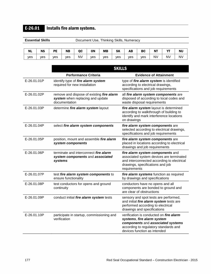
177 Red Seal Occupational Standard – Construction Electrician - 2015
E-26.01 Installs fire alarm systems. Essential Skills Document Use, Thinking Skills, Numeracy
NL NS PE NB QC ON MB SK AB BC NT YT NU
yes yes yes yes NV yes yes yes yes yes NV NV NV SKILLS
Performance Criteria Evidence of Attainment E-26.01.01P identify type of fire alarm system
required for new installation type of fire alarm system is identified according to electrical drawings, specifications and job requirements
E-26.01.02P remove and dispose of existing fire alarm system when replacing and update documentation
all fire alarm system components are disposed of according to local codes and waste disposal requirements
E-26.01.03P determine fire alarm system layout fire alarm system layout is determined according to walkthrough of building to identify and mark interference locations on drawings
E-26.01.04P select fire alarm system components fire alarm system components are selected according to electrical drawings, specifications and job requirements
E-26.01.05P position, mount and assemble fire alarm system components
fire alarm system components are placed in locations according to electrical drawings and job requirements
E-26.01.06P terminate and interconnect fire alarm system components and associated systems
fire alarm system components and associated system devices are terminated and interconnected according to electrical drawings, specifications and job requirements
E-26.01.07P test fire alarm system components to ensure functionality
fire alarm systems function as required by drawings and specifications
E-26.01.08P test conductors for opens and ground continuity
conductors have no opens and all components are bonded to ground and are clear of obstructions
E-26.01.09P conduct initial fire alarm system tests sensory and spot tests are performed, and initial fire alarm system tests are performed according to electrical drawings and specifications
E-26.01.10P participate in startup, commissioning and verification
verification is conducted on fire alarm systems, fire alarm system components and associated systems according to regulatory standards and devices function as intended

178 Red Seal Occupational Standard – Construction Electrician - 2015
RANGE OF VARIABLES fire alarm systems include: addressable (DCLA-DCLB-DCLC) and non-addressable (Class A – Class B) systems such as single stage/single zone, multi-zone, two stage fire alarm system components include: end of line devices (resistors, diodes), initiating devices (heat sensors, pull stations, fire/flame detectors, flow switches, gate valve switch, monitoring modules, smoke detectors, tamper switches) and signaling devices (horns, strobes, bells), panels (fire alarm panels [stand-by batteries], annunciator panels), relays associated systems include: fire suppression systems, emergency power supplies fan shutdown/startup, PA systems, local fire department, magnetic door holders, elevator homing contactors, egress door securing and releasing devices, building automation systems, ancillary devices (suppression system contactors and fans) KNOWLEDGE
Learning Outcomes Learning Objectives E-26.01.01L demonstrate knowledge of types of fire
alarm systems, their applications and operation
interpret codes and regulations pertaining to fire alarm systems
interpret information pertaining to fire alarm systems found on drawings and specifications
identify types of fire alarm systems and describe their characteristics and applications
describe types of associated systems that are interconnected with fire alarm systems
identify fire alarm system components and describe their characteristics and applications
identify the considerations and requirements for selecting fire alarm systems, and their components
E-26.01.02L demonstrate knowledge of the procedures used to install, upgrade and connect fire alarm systems and their components
describe the procedures used to install, upgrade and connect fire alarm systems and their components
describe procedures for testing fire alarm systems and their components
describe the procedures for the commissioning and verification of fire alarm systems

179 Red Seal Occupational Standard – Construction Electrician - 2015
RANGE OF VARIABLES fire alarm systems include: addressable (DCLA-DCLB-DCLC) and non-addressable (Class A – Class B) systems such as single stage/single zone, multi-zone, two stage codes and regulations include: CAN/ULC-S524, CAN/ULC-S536, CAN/ULC-S537, NBC, NFC and regulations specific to AHJ associated systems include: fire suppression systems, emergency power supplies fan shutdown/startup, PA systems, local fire department, magnetic door holders, elevator homing contactors, egress door securing and releasing devices, building automation systems, ancillary devices (suppression system contactors and fans) fire alarm system components include: end of line devices (resistors, diodes), initiating devices (heat sensors, pull stations, fire/flame detectors, flow switches, gate valve switch, monitoring modules, smoke detectors, tamper switches) and signaling devices (horns, strobes, bells), panels (fire alarm panels [stand-by batteries], annunciator panels), relays
E-26.02 Performs servicing and maintenance of fire alarm systems. Essential Skills Oral Communication, Digital Technology, Writing
NL NS PE NB QC ON MB SK AB BC NT YT NU
yes yes yes yes NV yes yes yes yes yes NV NV NV SKILLS
Performance Criteria Evidence of Attainment E-26.02.01P obtain detailed description of malfunction
of fire alarm system from client malfunction issues and information is obtained and description of problem is noted
E-26.02.02P identify existing fire alarm system and components
existing fire alarm system and components are identified from as-built drawings, maintenance log and site visit
E-26.02.03P test fire alarm system tests are performed according to maintenance schedule; sensory inspections and technical inspections are performed using diagnostic and test equipment
E-26.02.04P analyze test results test results are compared to manufacturers’ certification report and communication log, and client requirements
E-26.02.05P participate in periodic inspections fire alarm system, fire alarm system components, and associated systems function according to manufacturers’ specifications and are inspected according to maintenance schedule

180 Red Seal Occupational Standard – Construction Electrician - 2015
E-26.02.06P replace fire alarm system components as required
replacement components are tested and verified
E-26.02.07P update documentation to reflect servicing, testing, inspections or maintenance performed
documentation is clear, detailed and includes systems and components tested, the test results and changes that were completed
RANGE OF VARIABLES fire alarm systems include: addressable (DCLA-DCLB-DCLC) and non-addressable (Class A – Class B) systems such as single stage/single zone, multi-zone, two stage information includes: where and when problem occurred, has problem happened before, is it intermittent or consistent in nature, have any changes recently been made to the system, associated systems or building (painting or removing partitions), latest inspection report, maintenance logs fire alarm system components include: end of line devices (resistors, diodes), initiating devices (heat sensors, pull stations, fire/flame detectors, flow switches, gate valve switch, monitoring modules, smoke detectors, tamper switches) and signaling devices (horns, strobes, bells), panels (fire alarm panels [stand-by batteries], annunciator panels), relays diagnostic and test equipment includes: multimeters, voltage testers, sound pressure level (SPL) meters, heat lamp, smoke canisters associated systems include: fire suppression systems, emergency power supplies fan shutdown/startup, PA systems, local fire department, magnetic door holders, elevator homing contactors, egress door securing and releasing devices, building automation systems, ancillary devices (suppression system contactors and fans) documentation includes: maintenance logs, inspection reports, as-built drawings, panel schedules KNOWLEDGE
Learning Outcomes Learning Objectives E-26.02.01L demonstrate knowledge of fire alarm
systems, their applications and operation interpret codes and regulations pertaining to fire alarm systems
interpret information pertaining to fire alarm systems found on drawings and specifications
identify types of fire alarm systems and describe their characteristics and applications
identify fire alarm system components and describe their characteristics and applications
identify the considerations and requirements for selecting fire alarm systems and components
describe types of associated systems that interconnect with fire alarm systems

181 Red Seal Occupational Standard – Construction Electrician - 2015
E-26.02.02L demonstrate knowledge of the procedures used to service and maintain fire alarm systems
describe possible effects of fire alarm system service and maintenance on associated systems
describe the procedures used to service and maintain fire alarm systems and components
describe procedures for testing fire alarm systems and their components
RANGE OF VARIABLES fire alarm systems include: addressable (DCLA-DCLB-DCLC) and non-addressable (Class A – Class B) systems such as single stage/single zone, multi-zone, two stage codes and regulations include: CAN/ULC-S524, CAN/ULC-S536, CAN/ULC-S537, NBC, NFC and regulations specific to AHJ fire alarm system components include: end of line devices (resistors, diodes), initiating devices (heat sensors, pull stations, fire/flame detectors, flow switches, gate valve switch, monitoring modules, smoke detectors, tamper switches) and signaling devices (horns, strobes, bells), panels (fire alarm panels [stand-by batteries], annunciator panels), relays associated systems include: fire suppression systems, emergency power supplies fan shutdown/startup, PA systems, local fire department, magnetic door holders, elevator homing contactors, egress door securing and releasing devices, building automation systems
E-26.03 Installs security and surveillance systems. Essential Skills Document Use, Digital Technology, Numeracy
NL NS PE NB QC ON MB SK AB BC NT YT NU
no yes yes yes NV yes yes yes yes yes NV NV NV SKILLS
Performance Criteria Evidence of Attainment E-26.03.01P identify type of security and surveillance
system required for new installation type of security and surveillance system is identified according to electrical drawings, specifications and job requirements
E-26.03.02P remove and dispose of existing security and surveillance system when replacing and update documentation
all security and surveillance system components are disposed of in an environmentally conscious manner
E-26.03.03P determine security and surveillance system layout
security and surveillance system layout is determined according to architectural and client requirements
E-26.03.04P select security and surveillance system components
security and surveillance system components are selected according to electrical drawings, specifications, job and client requirements
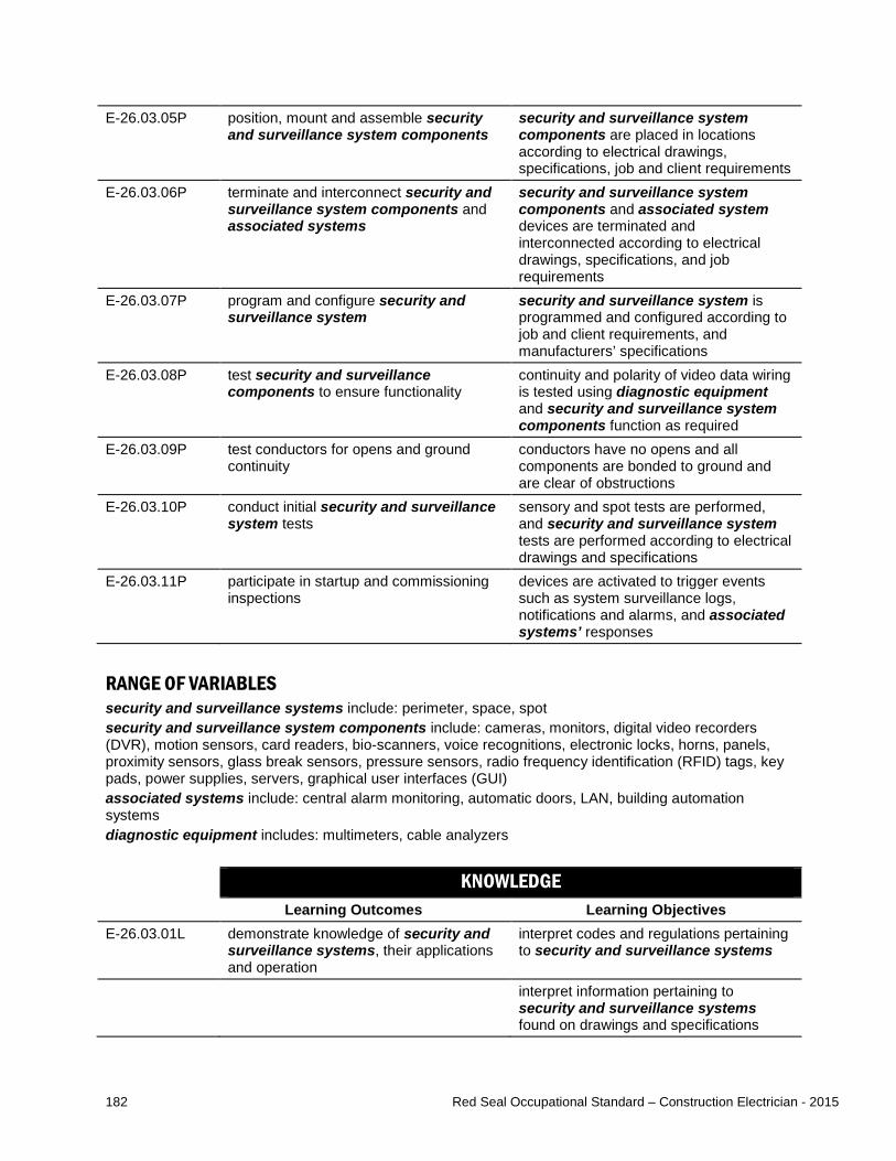
182 Red Seal Occupational Standard – Construction Electrician - 2015
E-26.03.05P position, mount and assemble security and surveillance system components
security and surveillance system components are placed in locations according to electrical drawings, specifications, job and client requirements
E-26.03.06P terminate and interconnect security and surveillance system components and associated systems
security and surveillance system components and associated system devices are terminated and interconnected according to electrical drawings, specifications, and job requirements
E-26.03.07P program and configure security and surveillance system
security and surveillance system is programmed and configured according to job and client requirements, and manufacturers’ specifications
E-26.03.08P test security and surveillance components to ensure functionality
continuity and polarity of video data wiring is tested using diagnostic equipment and security and surveillance system components function as required
E-26.03.09P test conductors for opens and ground continuity
conductors have no opens and all components are bonded to ground and are clear of obstructions
E-26.03.10P conduct initial security and surveillance system tests
sensory and spot tests are performed, and security and surveillance system tests are performed according to electrical drawings and specifications
E-26.03.11P participate in startup and commissioning inspections
devices are activated to trigger events such as system surveillance logs, notifications and alarms, and associated systems’ responses
RANGE OF VARIABLES security and surveillance systems include: perimeter, space, spot security and surveillance system components include: cameras, monitors, digital video recorders (DVR), motion sensors, card readers, bio-scanners, voice recognitions, electronic locks, horns, panels, proximity sensors, glass break sensors, pressure sensors, radio frequency identification (RFID) tags, key pads, power supplies, servers, graphical user interfaces (GUI) associated systems include: central alarm monitoring, automatic doors, LAN, building automation systems diagnostic equipment includes: multimeters, cable analyzers
KNOWLEDGE Learning Outcomes Learning Objectives
E-26.03.01L demonstrate knowledge of security and surveillance systems, their applications and operation
interpret codes and regulations pertaining to security and surveillance systems
interpret information pertaining to security and surveillance systems found on drawings and specifications

183 Red Seal Occupational Standard – Construction Electrician - 2015
identify types of security and surveillance systems and describe their characteristics and applications
describe types of associated systems that are interconnected with security and surveillance systems
identify security and surveillance system components and describe their characteristics and applications
E-26.03.02L demonstrate knowledge of the procedures used to install, upgrade and connect security and surveillance systems and their components
identify the considerations and requirements for selecting security and surveillance systems and their components
describe the procedures used to install, upgrade and connect security and surveillance systems and their components
describe procedures for testing security and surveillance systems, their components
describe the procedures for the commissioning and verification of security and surveillance systems
RANGE OF VARIABLES security and surveillance systems include: perimeter, space, spot security and surveillance system components include: cameras, monitors, DVRs, motion sensors, card readers, bio-scanners, voice recognitions, electronic locks, horns, panels, proximity sensors, glass break sensors, pressure sensors, RFID tags, key pads, power supplies, servers, GUIs associated systems include: central alarm monitoring, automatic doors, LAN, building automation systems

184 Red Seal Occupational Standard – Construction Electrician - 2015
E-26.04 Performs servicing and maintenance of security and surveillance systems. Essential Skills Oral Communication, Digital Technology, Numeracy
NL NS PE NB QC ON MB SK AB BC NT YT NU
no yes yes yes NV yes yes yes yes yes NV NV NV SKILLS
Performance Criteria Evidence of Attainment E-26.04.01P obtain detailed description of malfunction
of security and surveillance system from client
information is obtained and description of problem is noted
E-26.04.02P identify existing security and surveillance system and components
as-built drawings and maintenance log are referenced to identify existing security and surveillance system; walkthrough is conducted
E-26.04.03P program and configure security and surveillance system
security and surveillance system is programmed and configured according to job and client requirements
E-26.04.04P conduct security and surveillance system tests
tests are performed according to sensory inspections and technical inspections using diagnostic equipment and software
E-26.04.05P analyze test results test results are compared to security and surveillance log and client requirements
E-26.04.06P replace defective security and surveillance system components
replacement components are tested and verified
E-26.04.07P clean and adjust components component functionality (for example that sensors and recording devices cover required area) are restored to optimal conditions
E-26.04.08P update documentation to reflect servicing, testing, inspections or maintenance performed
documentation is clear and detailed and includes systems and components tested, the test results and changes that were completed
E-26.04.09P notify and explain system changes to system monitor
system changes are explained to system monitor

185 Red Seal Occupational Standard – Construction Electrician - 2015
RANGE OF VARIABLES security and surveillance systems include: perimeter, space, spot information includes: where and when problem occurred, has problem happened before, is it intermittent or consistent in nature, have any changes recently been made to the system, associated systems or building (painting or removing partitions), latest inspection report, maintenance logs security and surveillance system components include: cameras, monitors, DVRs, motion sensors, card readers, bio-scanners, voice recognition, electronic locks, horns, panels, proximity sensors, glass break sensors, pressure sensors, RFID tags, key pads, power supplies, servers, GUIs diagnostic equipment and software includes: multimeters, voltage testers, network cable analyzers, internal diagnostic software documentation includes: maintenance logs, as-builts
KNOWLEDGE Learning Outcomes Learning Objectives
E-26.04.01L demonstrate knowledge of security and surveillance systems, their applications and operation
interpret codes and regulations pertaining to security and surveillance systems
interpret information pertaining to security and surveillance systems found on drawings and specifications
identify types of security and surveillance systems and describe their characteristics and applications
identify security and surveillance system components and describe their characteristics and applications
identify the considerations and requirements for selecting security and surveillance systems and their components
describe types of associated systems that often interconnect with security and surveillance systems
E-26.04.02L demonstrate knowledge of the procedures used to service and maintain security and surveillance systems
describe possible effects of security and surveillance system service and maintenance on associated systems
describe the procedures used to service and maintain security and surveillance systems and their components
describe procedures for testing security and surveillance systems, their components and conductors
describe the procedures for the commissioning/verification of security and surveillance systems

186 Red Seal Occupational Standard – Construction Electrician - 2015
RANGE OF VARIABLES security and surveillance systems include: perimeter, space, spot security and surveillance system components include: cameras, monitors, DVRs, motion sensors, card readers, bio-scanners, voice recognitions, electronic locks, horns, panels, proximity sensors, glass break sensors, pressure sensors, RFID tags, key pads, power supplies, servers, GUIs associated systems include: central alarm monitoring, automatic doors, LAN, building automation systems
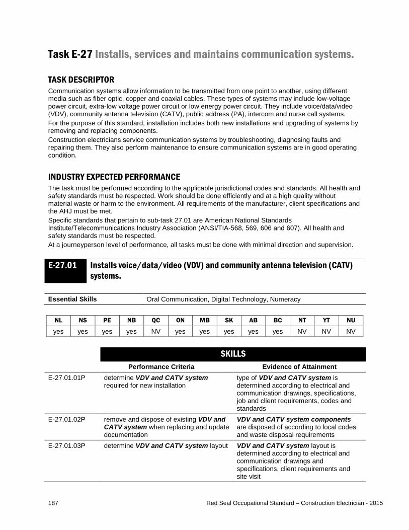
187 Red Seal Occupational Standard – Construction Electrician - 2015
Task E-27 Installs, services and maintains communication systems. TASK DESCRIPTOR Communication systems allow information to be transmitted from one point to another, using different media such as fiber optic, copper and coaxial cables. These types of systems may include low-voltage power circuit, extra-low voltage power circuit or low energy power circuit. They include voice/data/video (VDV), community antenna television (CATV), public address (PA), intercom and nurse call systems. For the purpose of this standard, installation includes both new installations and upgrading of systems by removing and replacing components. Construction electricians service communication systems by troubleshooting, diagnosing faults and repairing them. They also perform maintenance to ensure communication systems are in good operating condition. INDUSTRY EXPECTED PERFORMANCE The task must be performed according to the applicable jurisdictional codes and standards. All health and safety standards must be respected. Work should be done efficiently and at a high quality without material waste or harm to the environment. All requirements of the manufacturer, client specifications and the AHJ must be met. Specific standards that pertain to sub-task 27.01 are American National Standards Institute/Telecommunications Industry Association (ANSI/TIA-568, 569, 606 and 607). All health and safety standards must be respected. At a journeyperson level of performance, all tasks must be done with minimal direction and supervision.
E-27.01 Installs voice/data/video (VDV) and community antenna television (CATV) systems.
Essential Skills Oral Communication, Digital Technology, Numeracy
NL NS PE NB QC ON MB SK AB BC NT YT NU
yes yes yes yes NV yes yes yes yes yes NV NV NV SKILLS
Performance Criteria Evidence of Attainment E-27.01.01P determine VDV and CATV system
required for new installation type of VDV and CATV system is determined according to electrical and communication drawings, specifications, job and client requirements, codes and standards
E-27.01.02P remove and dispose of existing VDV and CATV system when replacing and update documentation
VDV and CATV system components are disposed of according to local codes and waste disposal requirements
E-27.01.03P determine VDV and CATV system layout VDV and CATV system layout is determined according to electrical and communication drawings and specifications, client requirements and site visit

188 Red Seal Occupational Standard – Construction Electrician - 2015
E-27.01.04P select VDV and CATV system components
VDV and CATV system components are selected according to electrical and communication drawings and specifications, building material finishes, drawings, job and client requirements
E-27.01.05P position, mount and assemble communication cabling raceway
communication cabling raceway is positioned, mounted and assembled according to manufacturers’ specifications, industry standards and CEC requirements
E-27.01.06P temporarily label and install cabling cabling is labeled and installed according to manufacturers’ specifications and CEC requirements
E-27.01.07P position, mount and assemble VDV and CATV system components
VDV and CATV system components are positioned, mounted and assembled according to electrical and communication drawings, and specifications, job and client requirements, codes and standards, are level, square, secure, follow building lines and functional and physically protected where required; all components are bonded
E-27.01.08P terminate and interconnect VDV and CATV system components and associated systems
VDV and CATV components and associated system devices are terminated and interconnected according to standards, electrical and communication drawings and specifications, and job requirements
E-27.01.09P test and label VDV and CATV system components
cable performance is confirmed to be within acceptable parameters using diagnostic and test equipment for the system
E-27.01.10P update documentation for manufacturer certification
as-builts are updated and documentation to support certification is completed
RANGE OF VARIABLES VDV and CATV systems include: unshielded twisted pair (UTP), screened twisted pair (ScTP), category 3, 5e, 6 and 6A, fiber optic, multi-mode and single-mode, coaxial, distributed antenna system (wireless) VDV and CATV system components include: cabling, termination blocks, outlet jacks, patch panels, face plates, patch cables, cable supports, cable management devices, surge protection devices, connectors, splice trays, cabinets, racks, power supplies, broadcast transmitters, receiving equipment, noise suppressors, satellite dishes, amplifiers, splitters, attenuators, terminators, bonding hardware communication cabling raceway include: cable trays, conduits, utility columns, finger rack/ducts, perimeter raceways, wire baskets associated systems include: telecommunication bonding systems, telephone systems, data systems, security and surveillance systems standards include: ANSI/TIA-568, 569, 606 and 607, Society of Cabling Telecommunications Engineers (SCTE) for CATV, Building Industry Consulting Services International (BICSI) diagnostic and test equipment for systems include: Coaxial and CATV (time-domain reflectometers [TDRs]), UTP/ScTP systems (optical time-domain reflectometers [OTDRs], cable analyzers), fiber optic systems (light source power meters, wire map testers and CATV cable analyzers)
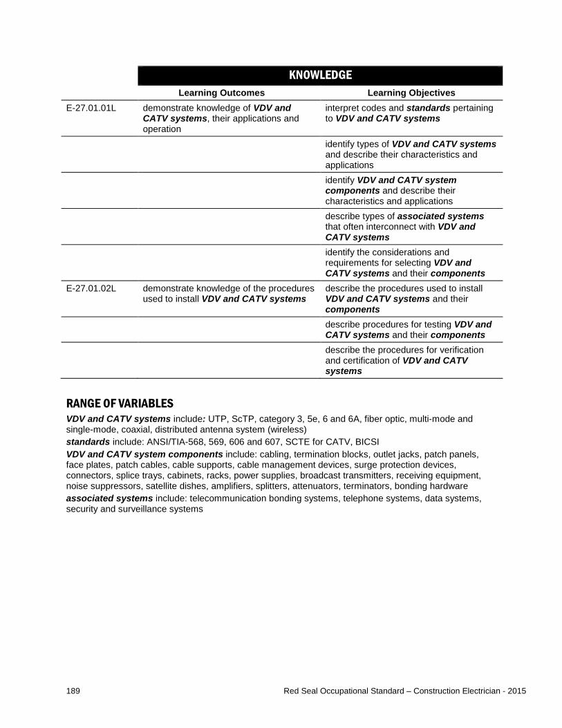
189 Red Seal Occupational Standard – Construction Electrician - 2015
KNOWLEDGE Learning Outcomes Learning Objectives
E-27.01.01L demonstrate knowledge of VDV and CATV systems, their applications and operation
interpret codes and standards pertaining to VDV and CATV systems
identify types of VDV and CATV systems and describe their characteristics and applications
identify VDV and CATV system components and describe their characteristics and applications
describe types of associated systems that often interconnect with VDV and CATV systems
identify the considerations and requirements for selecting VDV and CATV systems and their components
E-27.01.02L demonstrate knowledge of the procedures used to install VDV and CATV systems
describe the procedures used to install VDV and CATV systems and their components
describe procedures for testing VDV and CATV systems and their components
describe the procedures for verification and certification of VDV and CATV systems
RANGE OF VARIABLES VDV and CATV systems include: UTP, ScTP, category 3, 5e, 6 and 6A, fiber optic, multi-mode and single-mode, coaxial, distributed antenna system (wireless) standards include: ANSI/TIA-568, 569, 606 and 607, SCTE for CATV, BICSI VDV and CATV system components include: cabling, termination blocks, outlet jacks, patch panels, face plates, patch cables, cable supports, cable management devices, surge protection devices, connectors, splice trays, cabinets, racks, power supplies, broadcast transmitters, receiving equipment, noise suppressors, satellite dishes, amplifiers, splitters, attenuators, terminators, bonding hardware associated systems include: telecommunication bonding systems, telephone systems, data systems, security and surveillance systems
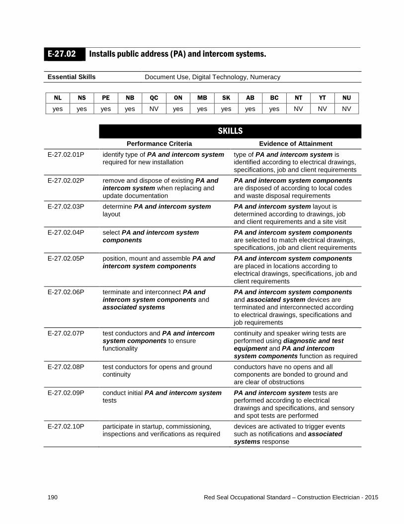
190 Red Seal Occupational Standard – Construction Electrician - 2015
E-27.02 Installs public address (PA) and intercom systems. Essential Skills Document Use, Digital Technology, Numeracy
NL NS PE NB QC ON MB SK AB BC NT YT NU
yes yes yes yes NV yes yes yes yes yes NV NV NV SKILLS
Performance Criteria Evidence of Attainment E-27.02.01P identify type of PA and intercom system
required for new installation type of PA and intercom system is identified according to electrical drawings, specifications, job and client requirements
E-27.02.02P remove and dispose of existing PA and intercom system when replacing and update documentation
PA and intercom system components are disposed of according to local codes and waste disposal requirements
E-27.02.03P determine PA and intercom system layout
PA and intercom system layout is determined according to drawings, job and client requirements and a site visit
E-27.02.04P select PA and intercom system components
PA and intercom system components are selected to match electrical drawings, specifications, job and client requirements
E-27.02.05P position, mount and assemble PA and intercom system components
PA and intercom system components are placed in locations according to electrical drawings, specifications, job and client requirements
E-27.02.06P terminate and interconnect PA and intercom system components and associated systems
PA and intercom system components and associated system devices are terminated and interconnected according to electrical drawings, specifications and job requirements
E-27.02.07P test conductors and PA and intercom system components to ensure functionality
continuity and speaker wiring tests are performed using diagnostic and test equipment and PA and intercom system components function as required
E-27.02.08P test conductors for opens and ground continuity
conductors have no opens and all components are bonded to ground and are clear of obstructions
E-27.02.09P conduct initial PA and intercom system tests
PA and intercom system tests are performed according to electrical drawings and specifications, and sensory and spot tests are performed
E-27.02.10P participate in startup, commissioning, inspections and verifications as required
devices are activated to trigger events such as notifications and associated systems response

191 Red Seal Occupational Standard – Construction Electrician - 2015
RANGE OF VARIABLES PA systems include: wired, wireless intercom systems include: one to one PA components include: microphones, speakers, amplifiers, bells, power supplies, tone generators, receivers intercom components include: call panels, unit panels, microphones, speakers, tone generators, handsets, door release strikes, GUIs, shielded conductors associated systems include: fire alarm systems, audio systems, telephone systems, security and surveillance systems diagnostic and test equipment includes: multimeters, ohmmeters
KNOWLEDGE Learning Outcomes Learning Objectives
E-27.02.01L demonstrate knowledge of PA and intercom systems, their applications and operation
interpret codes and regulations pertaining to PA and intercom systems
interpret information pertaining to PA and intercom systems found on drawings and specifications
identify types of PA and intercom systems and describe their characteristics and applications
describe types of associated systems that interconnect with PA and intercom systems
identify PA and intercom system components and describe their characteristics and applications
identify the considerations and requirements for selecting PA and intercom systems and their components
E-27.02.02L demonstrate knowledge of the procedures used to install, upgrade and connect PA and intercom systems
describe the procedures used to install, upgrade and connect PA and intercom systems and their components
describe procedures for testing PA and intercom systems, their components and conductors
RANGE OF VARIABLES PA systems include: perimeter, space intercom systems include: one to one associated systems include: fire alarm systems, audio systems, telephone systems, security and surveillance systems PA components include: microphones, speakers, amplifiers, bells, power supplies, tone generators, receivers intercom components include: call panels, unit panels, microphones, speakers, tone generators, handsets, door release strikes, GUIs, shielded conductors

192 Red Seal Occupational Standard – Construction Electrician - 2015
E-27.03 Installs nurse call systems. Essential Skills Document Use, Digital Technology, Numeracy
NL NS PE NB QC ON MB SK AB BC NT YT NU
yes yes yes yes NV yes yes yes yes yes NV NV NV SKILLS
Performance Criteria Evidence of Attainment E-27.03.01P identify type of nurse call system
required type of nurse call system is identified according to electrical drawings, specifications, job and client requirements
E-27.03.02P remove and dispose of existing nurse call system when replacing and update documentation
nurse call system components are disposed of according to local codes and waste disposal requirements
E-27.03.03P determine nurse call system layout nurse call system layout is determined according to drawings, client requirements and site visit
E-27.03.04P select nurse call system components nurse call system components are selected according to electrical drawings, specifications, job and client requirements
E-27.03.05P position, mount and assemble nurse call system components
nurse call system components are placed in locations according to electrical drawings, job and client requirements and manufacturers’ specifications
E-27.03.06P terminate and interconnect nurse call system components and associated systems
nurse call system components and associated system devices are terminated and interconnected according to electrical drawings, specifications and job requirements
E-27.03.07P test nurse call system components to ensure functionality
nurse call system components function as required
E-27.03.08P test conductors for opens and ground continuity using diagnostic and test equipment
conductors have no opens and all components are grounded and are clear of obstructions
E-27.03.09P conduct initial nurse call system tests nurse call system tests are performed according to electrical drawings and specifications and all devices are tested
E-27.03.10P label annunciation panels and devices for identification and servicing
initiating device and annunciating devices are labelled
E-27.03.11P participate in startup and commissioning inspections
devices are activated to trigger events such as notifications and alarms, and associated system responses
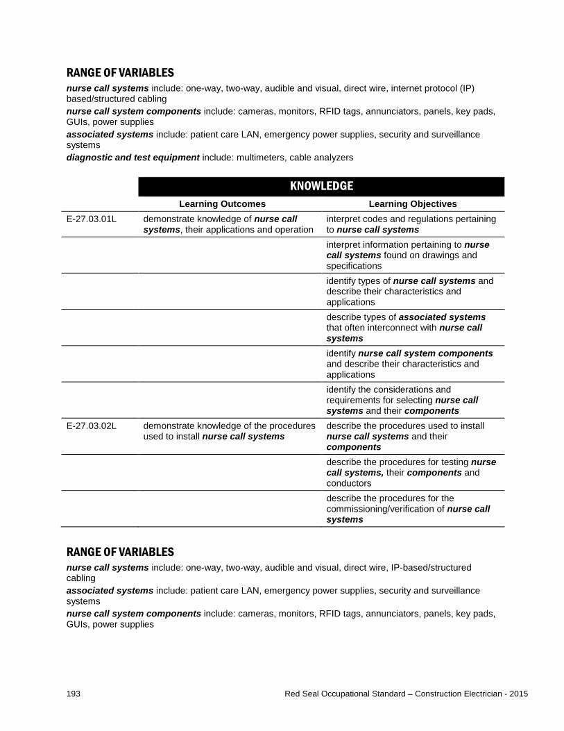
193 Red Seal Occupational Standard – Construction Electrician - 2015
RANGE OF VARIABLES nurse call systems include: one-way, two-way, audible and visual, direct wire, internet protocol (IP) based/structured cabling nurse call system components include: cameras, monitors, RFID tags, annunciators, panels, key pads, GUIs, power supplies associated systems include: patient care LAN, emergency power supplies, security and surveillance systems diagnostic and test equipment include: multimeters, cable analyzers KNOWLEDGE
Learning Outcomes Learning Objectives E-27.03.01L demonstrate knowledge of nurse call
systems, their applications and operation interpret codes and regulations pertaining to nurse call systems
interpret information pertaining to nurse call systems found on drawings and specifications
identify types of nurse call systems and describe their characteristics and applications
describe types of associated systems that often interconnect with nurse call systems
identify nurse call system components and describe their characteristics and applications
identify the considerations and requirements for selecting nurse call systems and their components
E-27.03.02L demonstrate knowledge of the procedures used to install nurse call systems
describe the procedures used to install nurse call systems and their components
describe the procedures for testing nurse call systems, their components and conductors
describe the procedures for the commissioning/verification of nurse call systems
RANGE OF VARIABLES nurse call systems include: one-way, two-way, audible and visual, direct wire, IP-based/structured cabling associated systems include: patient care LAN, emergency power supplies, security and surveillance systems nurse call system components include: cameras, monitors, RFID tags, annunciators, panels, key pads, GUIs, power supplies

194 Red Seal Occupational Standard – Construction Electrician - 2015
E-27.04 Performs servicing and maintenance of communication systems. Essential Skills Oral Communication, Digital Technology, Writing
NL NS PE NB QC ON MB SK AB BC NT YT NU
yes yes yes yes NV yes yes yes yes yes NV NV NV SKILLS
Performance Criteria Evidence of Attainment E-27.04.01P obtain detailed description of malfunction
of communication system from client malfunction issues and information are identified and recorded
E-27.04.02P identify existing communication system and components
existing communication system and components are identified from as-built drawings, maintenance log and certification report; walkthrough is performed
E-27.04.03P test communication system tests are performed according to sensory inspections and technical inspections using diagnostic and test equipment
E-27.04.04P analyze test results test results are compared to relevant documents such as manufacturers’ certification report, communication log and client requirements
E-27.04.05P replace communication system components
timing of replacement is scheduled with client; unintentional disruption of the system is avoided; replacement components are tested and verified
E-27.04.06P update documentation to reflect servicing, testing, inspections or maintenance performed
documentation is clear and detailed and includes systems and components tested, test results and changes completed
E-27.04.07P notify and explain system changes to client
client is informed of system changes

195 Red Seal Occupational Standard – Construction Electrician - 2015
RANGE OF VARIABLES communications systems include: VDV and CATV systems (UTP, ScTP, category 3, 5e, 6 and 6A, fiber optic, multi-mode and single-mode, coaxial and distributed antenna system [wireless]), PA systems (perimeter and space), intercom systems (one to one), nurse call systems (one-way, two-way, audible and visual, direct wire, IP based/structured cabling) communications system components include: VDV and CATV system components (cabling, termination blocks, outlet jacks, patch panels, face plates, patch cables, cable supports, cable management devices, surge protection for communication cabling systems, connectors, splice trays, cabinets, racks, power supplies, broadcast transmitters, receiving equipment, noise suppressors, satellite dishes, amplifiers, splitters, attenuators, terminators, bonding hardware), PA system components (microphones, speakers, amplifiers, bells, power supplies, tone generators, receivers), intercom components (call panels, unit panels, microphones, speakers, tone generators, handsets, door release strikes, GUIs, shielded conductors), nurse call system components (cameras, monitors, RFID tags, annunciator, panels, key pads, power supplies) diagnostic and test equipment includes: VDV and CATV systems (TDRs, OTDRs, cable analyzers, light source power meters, wire map testers and CATV cable analyzers), PA systems (multimeters, ohmmeters), nurse call systems (multimeters, cable analyzers)
KNOWLEDGE Learning Outcomes Learning Objectives
E-27.04.01L demonstrate knowledge of communication systems, their applications and operation
interpret codes, standards and regulations pertaining to communication systems
interpret information pertaining to communication systems found on drawings and specifications
identify types of communication systems and describe their characteristics and applications
identify communication system components and describe their characteristics and applications
describe types of associated systems that interconnect with communication systems
E-27.04.02L demonstrate knowledge of the procedures used to service and maintain communication systems
describe possible effects of communication system service and maintenance on associated systems
describe the procedures used to service and maintain communication systems and their components
describe procedures for testing communication systems, their components and conductors
describe the procedures for verification of communication systems
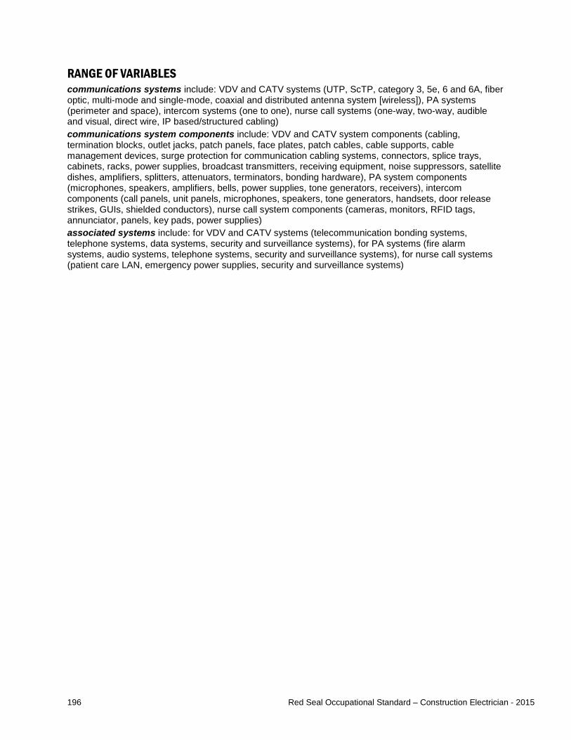
196 Red Seal Occupational Standard – Construction Electrician - 2015
RANGE OF VARIABLES communications systems include: VDV and CATV systems (UTP, ScTP, category 3, 5e, 6 and 6A, fiber optic, multi-mode and single-mode, coaxial and distributed antenna system [wireless]), PA systems (perimeter and space), intercom systems (one to one), nurse call systems (one-way, two-way, audible and visual, direct wire, IP based/structured cabling) communications system components include: VDV and CATV system components (cabling, termination blocks, outlet jacks, patch panels, face plates, patch cables, cable supports, cable management devices, surge protection for communication cabling systems, connectors, splice trays, cabinets, racks, power supplies, broadcast transmitters, receiving equipment, noise suppressors, satellite dishes, amplifiers, splitters, attenuators, terminators, bonding hardware), PA system components (microphones, speakers, amplifiers, bells, power supplies, tone generators, receivers), intercom components (call panels, unit panels, microphones, speakers, tone generators, handsets, door release strikes, GUIs, shielded conductors), nurse call system components (cameras, monitors, RFID tags, annunciator, panels, key pads, power supplies) associated systems include: for VDV and CATV systems (telecommunication bonding systems, telephone systems, data systems, security and surveillance systems), for PA systems (fire alarm systems, audio systems, telephone systems, security and surveillance systems), for nurse call systems (patient care LAN, emergency power supplies, security and surveillance systems)

197 Red Seal Occupational Standard – Construction Electrician - 2015
Task E-28 Installs, services and maintains integrated control systems. TASK DESCRIPTOR Integrated control systems and building automation systems involve connecting building components through a computerized system in order to achieve automated control over systems such as HVAC, lighting and security systems. For the purpose of this standard, installation includes both new installations and upgrading of systems by removing and replacing components. Construction electricians service integrated control systems and building automation systems by troubleshooting, diagnosing faults and repairing them. They also perform maintenance to ensure integrated control systems and building automation systems are in good operating condition. INDUSTRY EXPECTED PERFORMANCE The task must be performed according to the applicable jurisdictional codes and standards. Building Automation and Control Network (BACnet) and ANSI/TIA- 862 are specific standards that pertain to this task. All health and safety standards must be respected. Work should be done efficiently and at a high quality without material waste or harm to the environment. All requirements of the manufacturer, client specifications and the AHJ must be met. At a journeyperson level of performance, all tasks must be done with minimal direction and supervision.
E-28.01 Installs building automation systems. Essential Skills Document Use, Digital Technology, Numeracy
NL NS PE NB QC ON MB SK AB BC NT YT NU
yes yes yes yes NV yes yes yes yes yes NV NV NV SKILLS
Performance Criteria Evidence of Attainment E-28.01.01P identify type of building automation
system required for new installation type of building automation system is identified according to electrical, communication and mechanical drawings, and specifications, and job and client specifications
E-28.01.02P remove and dispose of existing building automation system when replacing and update documentation
building automation system components are disposed of according to local codes and waste disposal requirements
E-28.01.03P determine building automation system layout
building automation system layout is determined according to architectural electrical, communication, and mechanical drawings and specifications, job and client requirements, and site visit
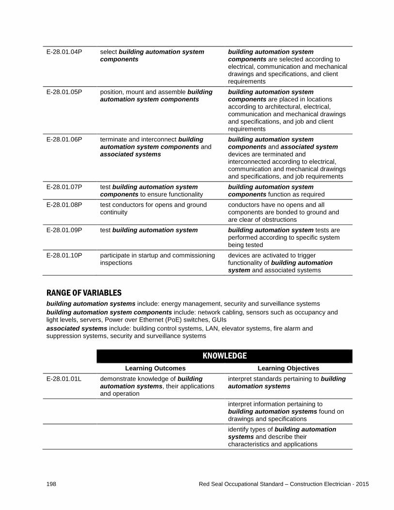
198 Red Seal Occupational Standard – Construction Electrician - 2015
E-28.01.04P select building automation system components
building automation system components are selected according to electrical, communication and mechanical drawings and specifications, and client requirements
E-28.01.05P position, mount and assemble building automation system components
building automation system components are placed in locations according to architectural, electrical, communication and mechanical drawings and specifications, and job and client requirements
E-28.01.06P terminate and interconnect building automation system components and associated systems
building automation system components and associated system devices are terminated and interconnected according to electrical, communication and mechanical drawings and specifications, and job requirements
E-28.01.07P test building automation system components to ensure functionality
building automation system components function as required
E-28.01.08P test conductors for opens and ground continuity
conductors have no opens and all components are bonded to ground and are clear of obstructions
E-28.01.09P test building automation system building automation system tests are performed according to specific system being tested
E-28.01.10P participate in startup and commissioning inspections
devices are activated to trigger functionality of building automation system and associated systems
RANGE OF VARIABLES building automation systems include: energy management, security and surveillance systems building automation system components include: network cabling, sensors such as occupancy and light levels, servers, Power over Ethernet (PoE) switches, GUIs associated systems include: building control systems, LAN, elevator systems, fire alarm and suppression systems, security and surveillance systems KNOWLEDGE
Learning Outcomes Learning Objectives E-28.01.01L demonstrate knowledge of building
automation systems, their applications and operation
interpret standards pertaining to building automation systems
interpret information pertaining to building automation systems found on drawings and specifications
identify types of building automation systems and describe their characteristics and applications

199 Red Seal Occupational Standard – Construction Electrician - 2015
identify building automation system components and describe their characteristics and applications
describe types of associated systems that interconnect with building automation systems
identify the considerations and requirements for selecting building automation systems and their components
E-28.01.02L demonstrate knowledge of the procedures used to install building automation systems
describe the procedures used to install building automation systems and their components
describe procedures for testing building automation systems and their components
describe the procedures for the commissioning and verification of building automation systems
RANGE OF VARIABLES building automation systems include: energy management, security and surveillance systems building automation system components include: network cabling, sensors such as occupancy and light levels, servers, PoE switches, GUIs associated systems include: building control system, LAN, elevator systems, fire alarm and suppression systems, security and surveillance systems
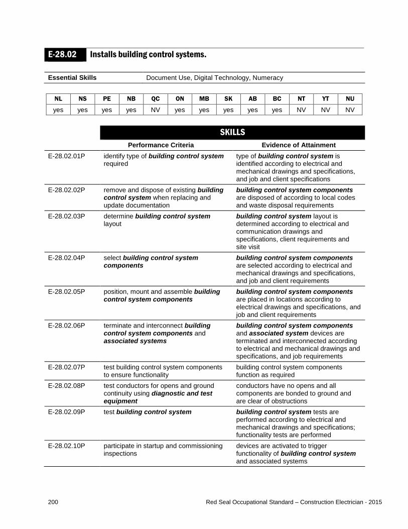
200 Red Seal Occupational Standard – Construction Electrician - 2015
E-28.02 Installs building control systems. Essential Skills Document Use, Digital Technology, Numeracy
NL NS PE NB QC ON MB SK AB BC NT YT NU
yes yes yes yes NV yes yes yes yes yes NV NV NV SKILLS
Performance Criteria Evidence of Attainment E-28.02.01P identify type of building control system
required type of building control system is identified according to electrical and mechanical drawings and specifications, and job and client specifications
E-28.02.02P remove and dispose of existing building control system when replacing and update documentation
building control system components are disposed of according to local codes and waste disposal requirements
E-28.02.03P determine building control system layout
building control system layout is determined according to electrical and communication drawings and specifications, client requirements and site visit
E-28.02.04P select building control system components
building control system components are selected according to electrical and mechanical drawings and specifications, and job and client requirements
E-28.02.05P position, mount and assemble building control system components
building control system components are placed in locations according to electrical drawings and specifications, and job and client requirements
E-28.02.06P terminate and interconnect building control system components and associated systems
building control system components and associated system devices are terminated and interconnected according to electrical and mechanical drawings and specifications, and job requirements
E-28.02.07P test building control system components to ensure functionality
building control system components function as required
E-28.02.08P test conductors for opens and ground continuity using diagnostic and test equipment
conductors have no opens and all components are bonded to ground and are clear of obstructions
E-28.02.09P test building control system building control system tests are performed according to electrical and mechanical drawings and specifications; functionality tests are performed
E-28.02.10P participate in startup and commissioning inspections
devices are activated to trigger functionality of building control system and associated systems

201 Red Seal Occupational Standard – Construction Electrician - 2015
RANGE OF VARIABLES building control systems include: pneumatic, analog electrical and direct digital control (DDC), computer control building control system components include: damper motors, valves, contactors, contacts, annunciators, thermostats, solenoids, flow and sail switches, and humidity, digital, analog, pressure differential, temperature, light level, occupancy and level/float sensors associated systems include: building automation systems, HVAC, lighting, security and surveillance systems diagnostic and test equipment include: multimeters KNOWLEDGE
Learning Outcomes Learning Objectives E-28.02.01L demonstrate knowledge of building
control systems, their applications and operation
interpret standards pertaining to building control systems
interpret information pertaining to building control systems found on drawings and specifications
identify types of building control systems and describe their characteristics and applications
identify building control system components and describe their characteristics and applications
describe types of associated systems that interconnect with building control systems
identify the considerations and requirements for selecting building control systems and their components
E-28.02.02L demonstrate knowledge of the procedures used to install building control systems
describe the procedures used to install building control systems and their components
describe the procedures for testing building control systems, their components and conductors
describe the procedures for the commissioning and verification of building control systems
RANGE OF VARIABLES building control systems include: pneumatic, analog electrical and DDC, computer control standards include: ANSI/ASHRAE 135 (BACnet), UL 916, ANSI/TIA 862 building control system components include: damper motors, valves, contactors, contacts, annunciators, thermostats, solenoids, flow and sail switches, and humidity, digital, analog, pressure differential, temperature, light level, occupancy and level/float sensors associated systems include: building automation systems, HVAC, lighting, security and surveillance systems
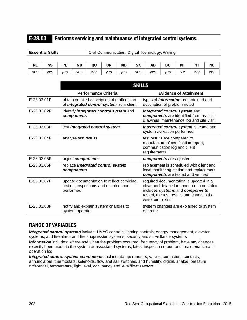
202 Red Seal Occupational Standard – Construction Electrician - 2015
E-28.03 Performs servicing and maintenance of integrated control systems. Essential Skills Oral Communication, Digital Technology, Writing
NL NS PE NB QC ON MB SK AB BC NT YT NU
yes yes yes yes NV yes yes yes yes yes NV NV NV SKILLS
Performance Criteria Evidence of Attainment E-28.03.01P obtain detailed description of malfunction
of integrated control system from client types of information are obtained and description of problem noted
E-28.03.02P identify integrated control system and components
integrated control system and components are identified from as-built drawings, maintenance log and site visit
E-28.03.03P test integrated control system integrated control system is tested and system activation performed
E-28.03.04P analyze test results test results are compared to manufacturers’ certification report, communication log and client requirements
E-28.03.05P adjust components components are adjusted E-28.03.06P replace integrated control system
components replacement is scheduled with client and local monitoring station and replacement components are tested and verified
E-28.03.07P update documentation to reflect servicing, testing, inspections and maintenance performed
required documentation is updated in a clear and detailed manner; documentation includes systems and components tested, the test results and changes that were completed
E-28.03.08P notify and explain system changes to system operator
system changes are explained to system operator
RANGE OF VARIABLES integrated control systems include: HVAC controls, lighting controls, energy management, elevator systems, and fire alarm and fire suppression systems, security and surveillance systems information includes: where and when the problem occurred, frequency of problem, have any changes recently been made to the system or associated systems, latest inspection report and, maintenance and operation log integrated control system components include: damper motors, valves, contactors, contacts, annunciators, thermostats, solenoids, flow and sail switches, and humidity, digital, analog, pressure differential, temperature, light level, occupancy and level/float sensors
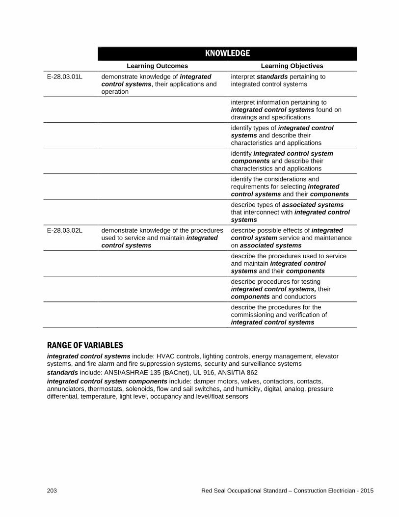
203 Red Seal Occupational Standard – Construction Electrician - 2015
KNOWLEDGE Learning Outcomes Learning Objectives
E-28.03.01L demonstrate knowledge of integrated control systems, their applications and operation
interpret standards pertaining to integrated control systems
interpret information pertaining to integrated control systems found on drawings and specifications
identify types of integrated control systems and describe their characteristics and applications
identify integrated control system components and describe their characteristics and applications
identify the considerations and requirements for selecting integrated control systems and their components
describe types of associated systems that interconnect with integrated control systems
E-28.03.02L demonstrate knowledge of the procedures used to service and maintain integrated control systems
describe possible effects of integrated control system service and maintenance on associated systems
describe the procedures used to service and maintain integrated control systems and their components
describe procedures for testing integrated control systems, their components and conductors
describe the procedures for the commissioning and verification of integrated control systems
RANGE OF VARIABLES integrated control systems include: HVAC controls, lighting controls, energy management, elevator systems, and fire alarm and fire suppression systems, security and surveillance systems standards include: ANSI/ASHRAE 135 (BACnet), UL 916, ANSI/TIA 862 integrated control system components include: damper motors, valves, contactors, contacts, annunciators, thermostats, solenoids, flow and sail switches, and humidity, digital, analog, pressure differential, temperature, light level, occupancy and level/float sensors
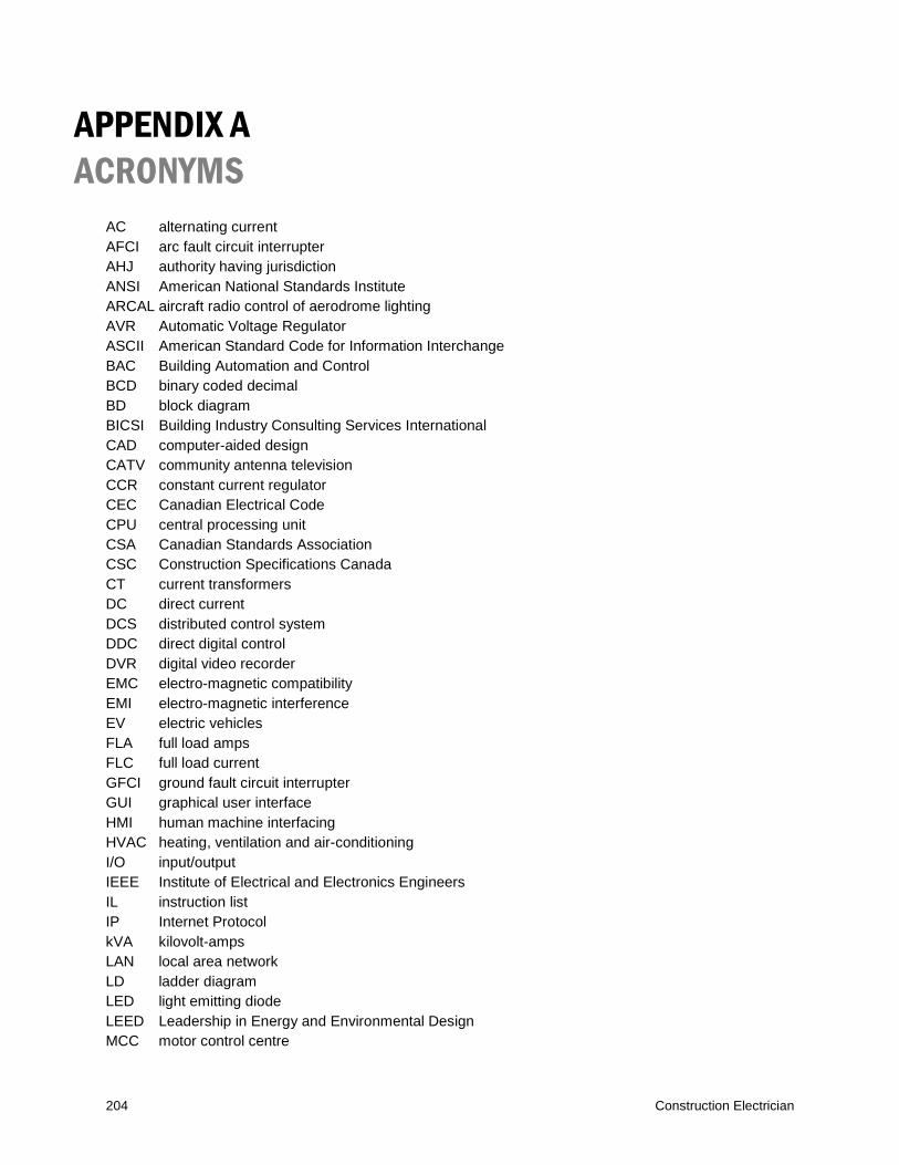
204 Construction Electrician
APPENDIX A ACRONYMS
AC alternating current AFCI arc fault circuit interrupter AHJ authority having jurisdiction ANSI American National Standards Institute ARCAL aircraft radio control of aerodrome lighting AVR Automatic Voltage Regulator ASCII American Standard Code for Information Interchange BAC Building Automation and Control BCD binary coded decimal BD block diagram BICSI Building Industry Consulting Services International CAD computer-aided design CATV community antenna television CCR constant current regulator CEC Canadian Electrical Code CPU central processing unit CSA Canadian Standards Association CSC Construction Specifications Canada CT current transformers DC direct current DCS distributed control system DDC direct digital control DVR digital video recorder EMC electro-magnetic compatibility EMI electro-magnetic interference EV electric vehicles FLA full load amps FLC full load current GFCI ground fault circuit interrupter GUI graphical user interface HMI human machine interfacing HVAC heating, ventilation and air-conditioning I/O input/output IEEE Institute of Electrical and Electronics Engineers IL instruction list IP Internet Protocol kVA kilovolt-amps LAN local area network LD ladder diagram LED light emitting diode LEED Leadership in Energy and Environmental Design MCC motor control centre

205 Construction Electrician
MOV metal oxide varistor MSDS material safety data sheets NBC National Building Code NEMA National Electrical Manufacturers’ Association NETA North American Electrical Testing Association NFC National Fire Code O&M operations and maintenance OEM original equipment manufacturer OH&S Occupational Health and Safety OTDR optical time-domain reflectometer OTE output energized PA public address PDC power distribution centre PLC programmable logic controller PoE power over Ethernet PPE personal protective equipment PQA Power Quality Analyzer PT potential transformers RFID radio frequency identification SCADA Supervisory Control and Data Acquisition SCTE Society of Cabling Telecommunications Engineers ScTP screened twisted pair SPL sound pressure level SFC sequential function chart ST structured test TDR time-domain reflectometer TIA Telecommunications Industry Association ULC Underwriters Laboratories of Canada UPS uninterruptible power supply UTP unshielded twisted pair VDV voice / data / video VFD variable frequency drive WHMIS Workplace Hazardous Materials Information System WLL working load limit XIO examine if opened XIC examine if closed
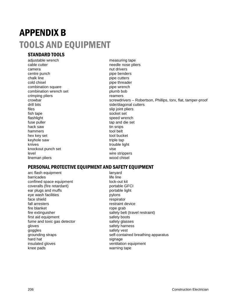
206 Construction Electrician
APPENDIX B TOOLS AND EQUIPMENT
STANDARD TOOLS adjustable wrench measuring tape cable cutter needle nose pliers camera nut drivers centre punch pipe benders chalk line pipe cutters cold chisel pipe threader combination square pipe wrench combination wrench set plumb bob crimping pliers reamers crowbar screwdrivers – Robertson, Phillips, torx, flat, tamper-proof drill bits side/diagonal cutters files slip joint pliers fish tape socket set flashlight speed wrench fuse puller tap and die set hack saw tin snips hammers tool belt hex key set tool bucket keyhole saw triple tap knives trouble light knockout punch set vise level wire strippers lineman pliers wood chisel PERSONAL PROTECTIVE EQUIPMENT AND SAFETY EQUIPMENT arc flash equipment lanyard barricades life line confined space equipment lock-out kit coveralls (fire retardant) portable GFCI ear plugs and muffs portable light eye wash facilities pylons face shield respirator fall arresters restraint device fire blanket rope grab fire extinguisher safety belt (travel restraint) first aid equipment safety boots fume and toxic gas detector safety glasses gloves safety harness goggles safety vest grounding straps self-contained breathing apparatus hard hat signage insulated gloves ventilation equipment knee pads warning tape

207 Construction Electrician
ACCESS EQUIPMENT articulated boom lift scaffolds (rolling, mechanical, stationary, ladder jack) boom lifts man basket construction elevator scissor lift ladders (extension, fixed, step) swing stage lift table POWER TOOLS AND EQUIPMENT band saws knock-out punch (powered) battery/rechargeable drill magnetic drill bench grinder pneumatic hammer drill cable puller power cable feeders chop saw power drill circular saw power pipe bender core drill power pipe cutters drill press power pipe threader grinder power puller heat gun power reel lift hammer drill PVC bender hole saw kit reciprocating saw power crimper sump pump jig saw vacuum SPECIALTY TOOLS AND EQUIPMENT chain falls powder-actuated tools come-along reel jacks communication devices (cellphones and 2-way
radio) rope
creepers and crawlers shackles extension cords shovels grip hoist sledgehammer hot stick slings inverters spud wrench laser level soldering apparatus manual hoist strain relief grips picks thermit (thermal) welder pneumatic hoist torque wrench portable generator wire rack

208 Construction Electrician
MEASURING EQUIPMENT ammeter optical time-domain reflectometer (OTDR) cable locator ohmmeter clamp ammeter oscilloscope fault locator phase/motor rotation meter frequency meter power quality analyzer ground megohmmeter recording meter (watts, volts and amps) high pot tester (dielectric tester) tachometer inductive voltage detector (non-contact voltage
detector) thermographic imaging device
insulation resistance tester thermometer (infra-red and electronic) jumpers ultrasonic testing equipment LAN meter (cable analyzer) voltage tester light meter voltmeter megohmmeter (insulation tester) watt meter multimeter

209 Construction Electrician
APPENDIX C GLOSSARY
ancillary functions performed by the fire alarm system as an output of the fire alarm system, controlled by a relay or similar device, for example, elevator recall, fan shut down and door release
bonding a low impedance path obtained by permanently joining all non-current-carrying metal parts to assure electrical continuity and having the capacity to conduct safely any current likely to be imposed on it
cathodic protection technique to control the corrosion of a metal surface by making that surface the cathode of an electrochemical cell
extra low voltage any voltage not exceeding 30V grounding a permanent and continuous conductive path to the earth with sufficient
ampacity to carry any fault current liable to be imposed on it, and of a sufficiently low impedance to limit the voltage rise above ground and to facilitate the operation of the protective devices in the circuit
high voltage any voltage exceeding 750V low energy power
circuit a circuit where the power is limited to 100 Volt Amperes (VA) where V is the open circuit voltage
low voltage any voltage exceeding 30V but not exceeding 750V luminaires a complete lighting unit designed to accommodate the lamp(s) and to connect
the lamp(s) to circuit conductors, for example, florescent, High Intensity Discharge (HID) and incandescent
raceway any channel designed for holding wires, cables, or busbars, and, unless otherwise qualified by rules of the CEC, the term includes conduit (rigid, flexible, metal, non-metallic), electrical metallic and non-metallic tubing, underfloor raceways, cellular floors, surface raceways, wireways, cable trays, busways, and auxiliary gutters
specifications an explicit set of requirements to be satisfied by a material, product or service including but not limited to local and national building codes, any documentation that holds legal obligations, schematics, manufacturers specs, local code, provincial/federal authority, engineered drawings and diagrams and schematics, client requirements, warranty documents, site drawings, shop drawings, company requirements