Embed Size (px)
Citation preview
ISBN 978-3-938666-63-0
9 7 8 3 9 3 8 6 6 6 6 3 0
Arc
hite
ctur
al R
ende
rings
Fabi
o S
chill
aci
Construction and Design ManualArchitecturalRenderings
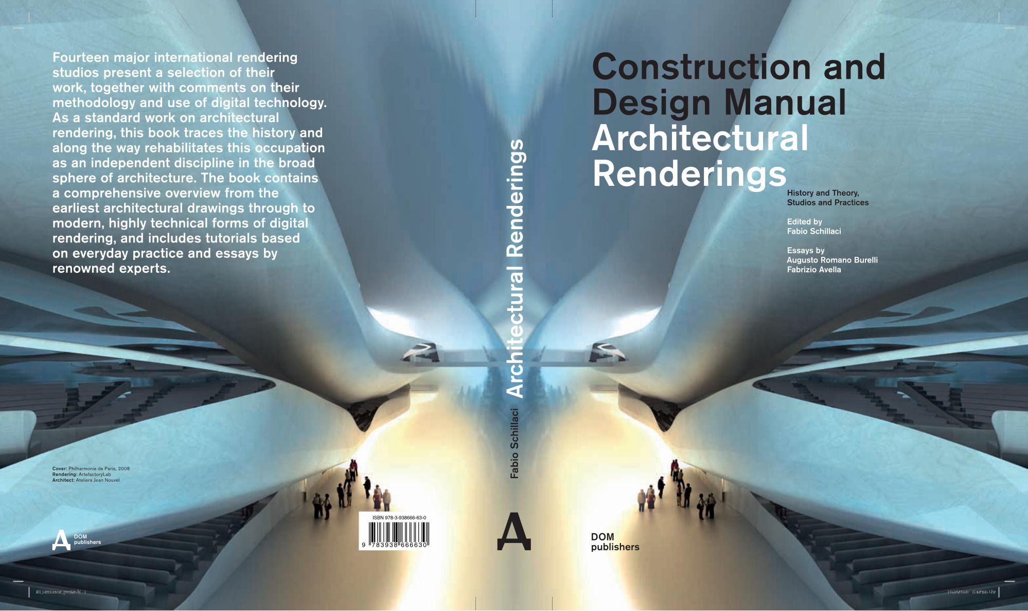
Fourteen major international rendering studios present a selection of their work, together with comments on their methodology and use of digital technology. As a standard work on architectural rendering, this book traces the history and along the way rehabilitates this occupation as an independent discipline in the broad sphere of architecture. The book contains a comprehensive overview from the earliest architectural drawings through to modern, highly technical forms of digital rendering, and includes tutorials based on everyday practice and essays by renowned experts.
Cover: Philharmonie de Paris, 2008 Rendering: ArtefactoryLab Architect: Ateliers Jean Nouvel
History and Theory, Studios and Practices
Edited byFabio Schillaci
Essays byAugusto Romano Burelli Fabrizio Avella
63_Hardcover_print.indd 1 18.09.2009 11:52:55 Uhr
Fabio SchillaciConstruction and Design ManualArchitectural Renderings
To Julienne and my family
Fabio SchillaciConstruction and Design ManualArchitectural Renderings
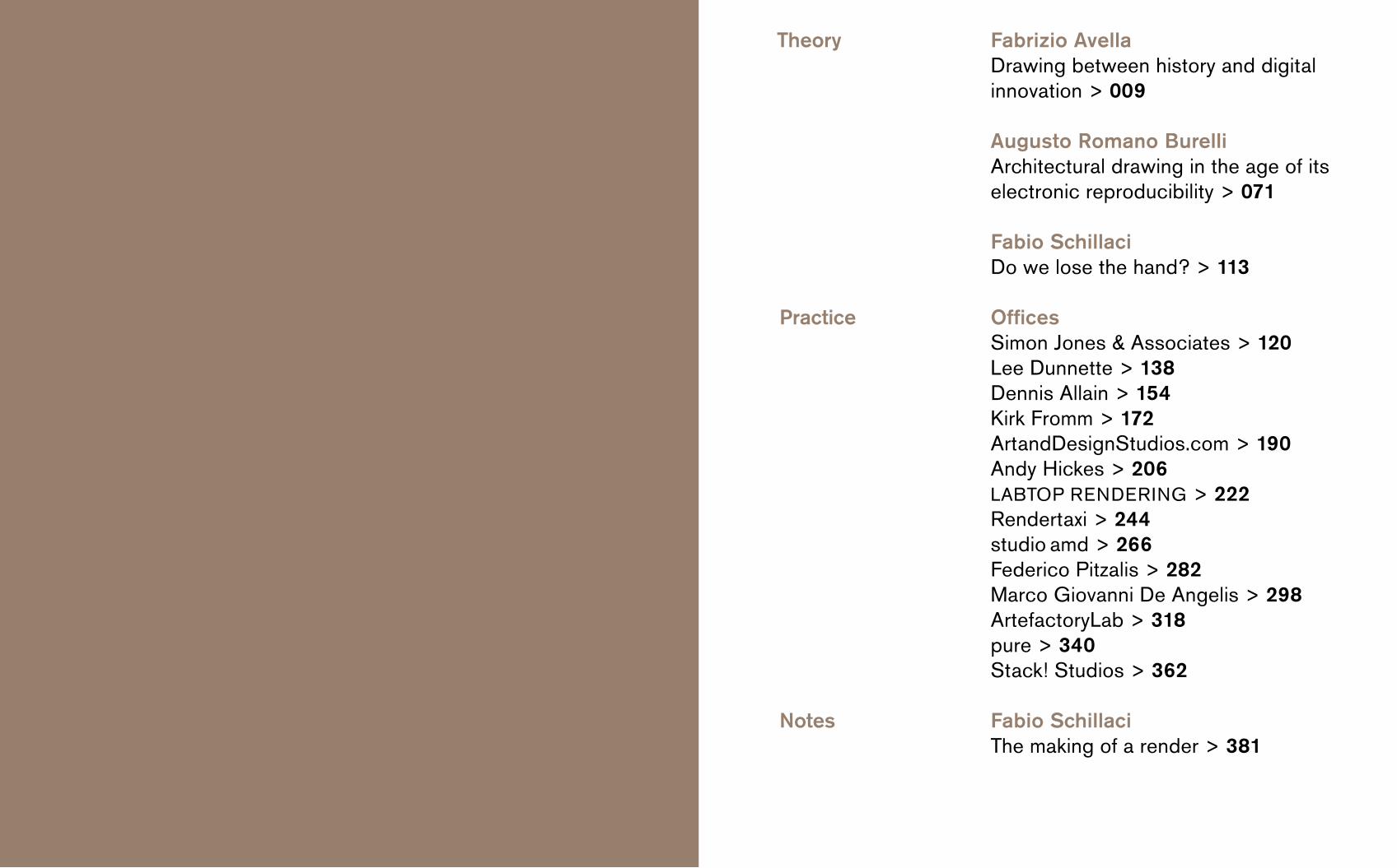
Fabrizio AvellaDrawing between history and digital innovation > 009
Augusto Romano BurelliArchitectural drawing in the age of its electronic reproducibility > 071
Fabio SchillaciDo we lose the hand? > 113
Offices Simon Jones & Associates > 120Lee Dunnette > 138Dennis Allain > 154Kirk Fromm > 172ArtandDesignStudios.com > 190Andy Hickes > 206LABTOP RENDERING > 222Rendertaxi > 244studio amd > 266 Federico Pitzalis > 282Marco Giovanni De Angelis > 298ArtefactoryLab > 318pure > 340Stack! Studios > 362
Fabio SchillaciThe making of a render > 381
Theory
Practice
Notes
discover that the most famous architectural companies in the world were outsourcing their rendering instead of doing them on their own. This led me – largely through the inter net – to discover a huge number of specialized offices doing architectural rendering. I invited the best fourteen to present and explain their work in the book. They were mostly enthusiastic about my invitation, and gave me motivation to go on with the project. Each of them agreed to publish its best images and to answer my questions concerning their work, philosophy and process. This was a big opportunity for me to learn, and so I want to pass you this knowledge too. Although each office works digitally, they do it in different ways. Their presentation goes from hand to computer, which means a way to think – and consequently draw – instead of a technical issue. The gallery is definitely a way to thank all the offices and to praise them for their great work. I am sure you probably already know some renderings because they are very famous, but you maybe do not know the name of their author.
Mostly people do not understand what rendering means, and underestimate the work. Thus, in conclusion, I de cided to show the making of render through my own work. The aim of this section is to show the process and the amount of work behind the rendering, and even if for a professional renderer this will not be a comprehensive tutorial,
I am sure this will help beginners and clients to understand more about our work and skills. Hopefully, this will also open architecture students’ minds about using digital technologies.
Fabio Schillaci
Mostly people think architectural rendering is something new and uniquely related to the computer. This is not totally true. A “render” is any depiction or interpretation that evokes something already existing or yet to exist. It does not matter if it is made digitally or by hand. We should not divide the digital from the handmade, actually it is about the same line of evolution. There would never be the digital render without the handdrawing.
In the light of the discussion about representation and the question whether digital technologies have changed the drawing paradigm, I asked Fabrizio Avella to write about the history of architectural representation for this book, and to focus especially on the tools and the way they changed the art over the course of the centuries. Avella’s essay is a very important summary of information which demonstrates that the logic used throughout history by the masters in handdrawing is the same applied today in the digital software.
So if that is true, why there is still so much reluctance to accept the digital paradigm? This was the question I wanted to ask Augusto Romano Burelli. His position was very critical about contemporary ways of using the computer. He pointed me out that the problem lies not in the tool, but in the way we use it: the computer is today becoming
the end rather than the means. Using computers implies accepting the risks of progress, but we should know the risks in order to control the tool and to not exaggerate. This is what happened to the ancient Greeks who built the Olimpieion in the colony of Akragas – today’s Agrigento in Italy. They tried to build a temple which was too big for the technical skills of the time, and fell down around the heads of its architects. This is the sin of hubris, arrogance, that Burelli reveals through incredible handmade drawings which reconstruct the architecture of the temple starting from the few ruins still present today. Quite the opposite of hubris are two works by Fiorenzo Bertan and his students at IUAV in Venice, which use computer and digital technologies in a way Burelli prizes. These are the the digital reconstruction of the Palladian Ponte di Rialto through a Canaletto “Capriccio”, which render with objectivity a completely out of scale architectural vision, and the case of the old Venetian boat “Sampierota” where the computer is used to document its manufacturing and to transmit it to the next generation, thus avoiding the disappearance of a handcrafted art without a manual.
When I began the research for this book, I had the chance to search for the – in my opinion – most interesting architectural rendering studios in the world. Because of my lack of professional experience, I was totally surprise to
Preamble
6 7
Fabrizio Avella Drawing between history and digital innovation
The introduction of digital processing techniques in architectural drawing has, in recent years, shaken the foundations of the drawing discipline. The aim of this essay is to determine what, conceptually, has remained unchanged compared to the codes of the manual drawing and how much it proposes itself as the new structure of thought. Considering technique as a dimension that creates thought with a set of biunivocal reports, one wonders if and how the use of new skills can influence and change the way we represent, and, therefore, think about architecture. In order to do this it is necessary to reflect on the codes of the methods and techniques of representation, focusing on those aspects which may help us to understand whether and how these codes have been impaired or accepted in the pro cesses of digital drawing.
The plan
It is very difficult to determine how long the plan has been used to describe architecture. The first method of representation mentioned by Vitruvio is iconography, the footprint of an object left on the soil, and traces of this method are found as early as 7200 BC.1
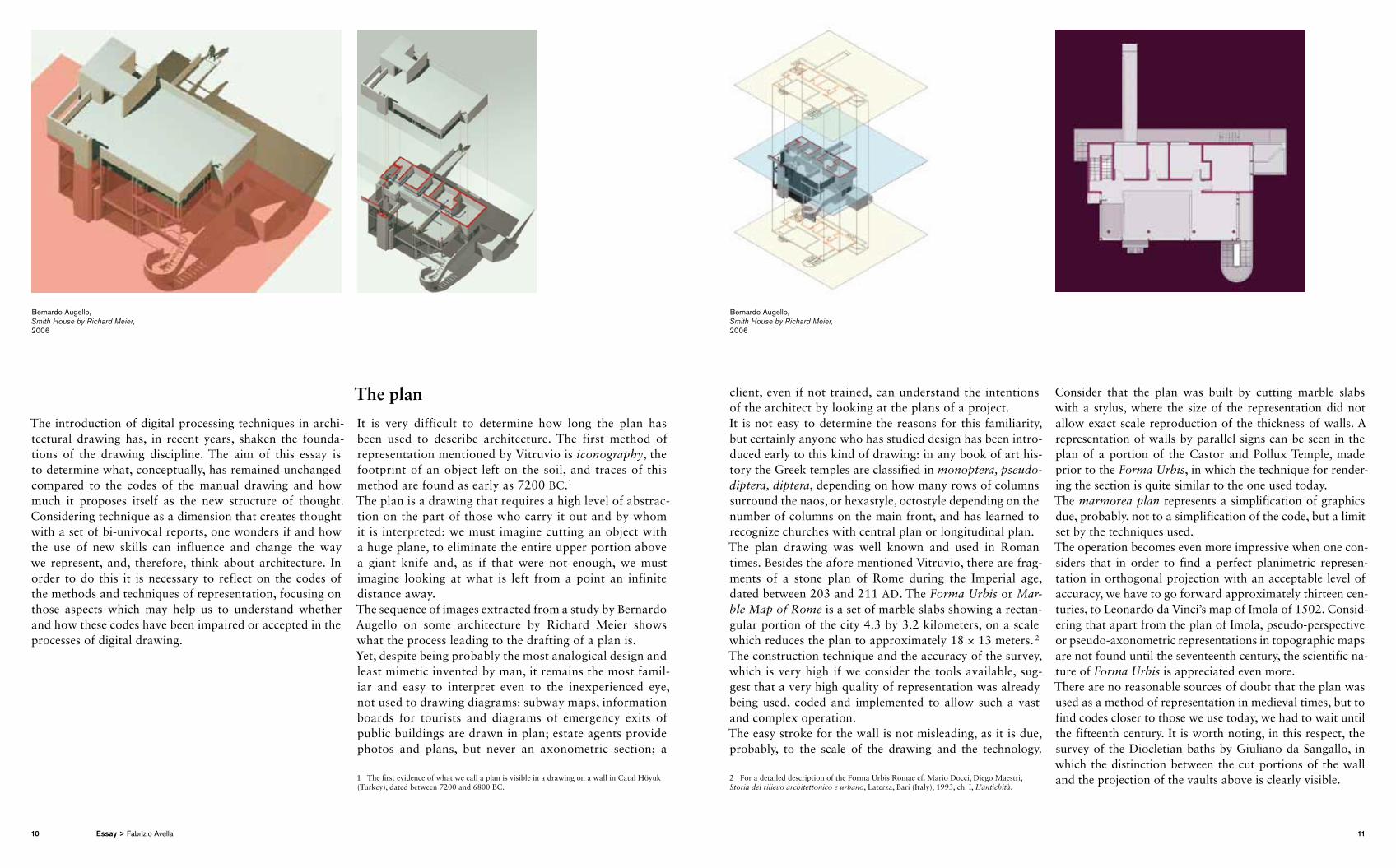
The plan is a drawing that requires a high level of abstraction on the part of those who carry it out and by whom it is interpreted: we must imagine cutting an object with a huge plane, to eliminate the entire upper portion above a giant knife and, as if that were not enough, we must imagine looking at what is left from a point an infinite distance away.The sequence of images extracted from a study by Bernardo Augello on some architecture by Richard Meier shows what the process leading to the drafting of a plan is.Yet, despite being probably the most analogical design and least mimetic invented by man, it remains the most familiar and easy to interpret even to the inexperienced eye, not used to drawing diagrams: subway maps, information boards for tourists and diagrams of emergency exits of public buildings are drawn in plan; estate agents provide photos and plans, but never an axonometric section; a
1 The first evidence of what we call a plan is visible in a drawing on a wall in Catal Höyuk (Turkey), dated between 7200 and 6800 BC.
client, even if not trained, can understand the intentions of the architect by looking at the plans of a project.It is not easy to determine the reasons for this familiarity, but certainly anyone who has studied design has been introduced early to this kind of drawing: in any book of art history the Greek temples are classified in monoptera, pseudo-diptera, diptera, depending on how many rows of columns surround the naos, or hexastyle, octostyle depending on the number of columns on the main front, and has learned to recognize churches with central plan or longitudinal plan.The plan drawing was well known and used in Roman times. Besides the afore mentioned Vitruvio, there are fragments of a stone plan of Rome during the Imperial age, dated between 203 and 211 AD. The Forma Urbis or Mar-ble Map of Rome is a set of marble slabs showing a rectangular portion of the city 4.3 by 3.2 kilometers, on a scale which reduces the plan to approximately 18 × 13 meters. 2 The construction technique and the accuracy of the survey, which is very high if we consider the tools available, suggest that a very high quality of representation was already being used, coded and implemented to allow such a vast and complex operation.The easy stroke for the wall is not misleading, as it is due, probably, to the scale of the drawing and the technology.
2 For a detailed description of the Forma Urbis Romae cf. Mario Docci, Diego Maestri, Storia del rilievo architettonico e urbano, Laterza, Bari (Italy), 1993, ch. I, L’antichità.
Consider that the plan was built by cutting marble slabs with a stylus, where the size of the representation did not allow exact scale reproduction of the thickness of walls. A representation of walls by parallel signs can be seen in the plan of a portion of the Castor and Pollux Temple, made prior to the Forma Urbis, in which the technique for rendering the section is quite similar to the one used today.The marmorea plan represents a simplification of graphics due, probably, not to a simplification of the code, but a limit set by the techniques used.The operation becomes even more impressive when one considers that in order to find a perfect planimetric representation in orthogonal projection with an acceptable level of accuracy, we have to go forward approximately thirteen centuries, to Leonardo da Vinci’s map of Imola of 1502. Considering that apart from the plan of Imo la, pseudoperspective or pseudoaxonometric representations in topographic maps are not found until the seventeenth century, the scientific nature of Forma Urbis is appreciated even more.There are no reasonable sources of doubt that the plan was used as a method of representation in medieval times, but to find codes closer to those we use today, we had to wait until the fifteenth century. It is worth noting, in this respect, the survey of the Diocletian baths by Giuliano da Sangallo, in which the distinction between the cut portions of the wall and the projection of the vaults above is clearly visible.
Bernardo Augello, Smith House by Richard Meier, 2006
Bernardo Augello, Smith House by Richard Meier, 2006
10 11Essay > Fabrizio Avella
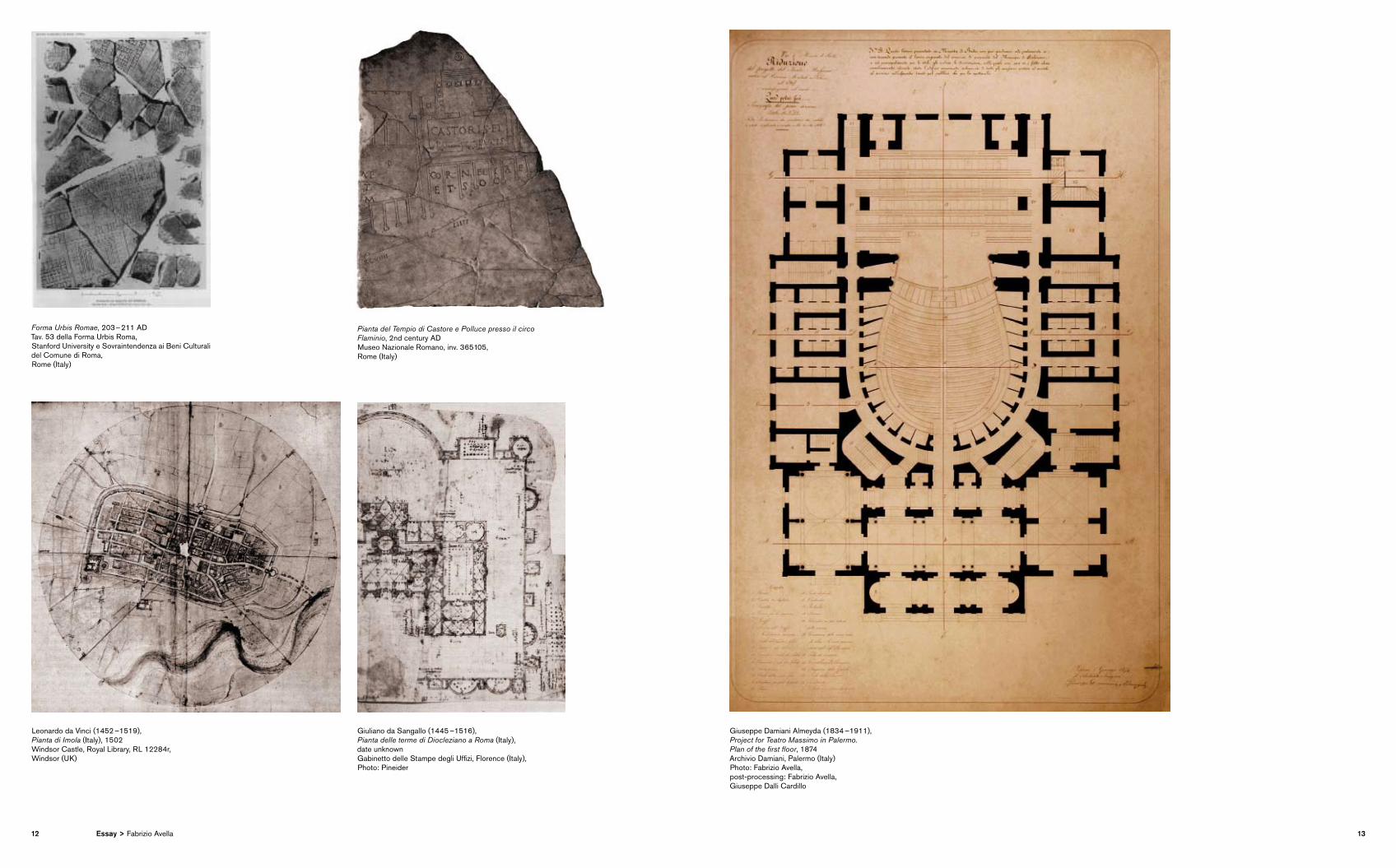
Forma Urbis Romae, 203 – 211 ADTav. 53 della Forma Urbis Roma, Stanford University e Sovraintendenza ai Beni Culturali del Comune di Roma, Rome (Italy)
Pianta del Tempio di Castore e Polluce presso il circo Flaminio, 2nd century ADMuseo Nazionale Romano, inv. 365105, Rome (Italy)
Leonardo da Vinci (1452 –1519), Pianta di Imola (Italy), 1502 Windsor Castle, Royal Library, RL 12284r, Windsor (UK)
Giuliano da Sangallo (1445 –1516), Pianta delle terme di Diocleziano a Roma (Italy), date unknown Gabinetto delle Stampe degli Uffizi, Florence (Italy), Photo: Pineider
Giuseppe Damiani Almeyda (1834 –1911), Project for Teatro Massimo in Palermo. Plan of the first floor, 1874 Archivio Damiani, Palermo (Italy) Photo: Fabrizio Avella, post-processing: Fabrizio Avella, Giuseppe Dalli Cardillo
12 13Essay > Fabrizio Avella
Orthogonal projections and flat section
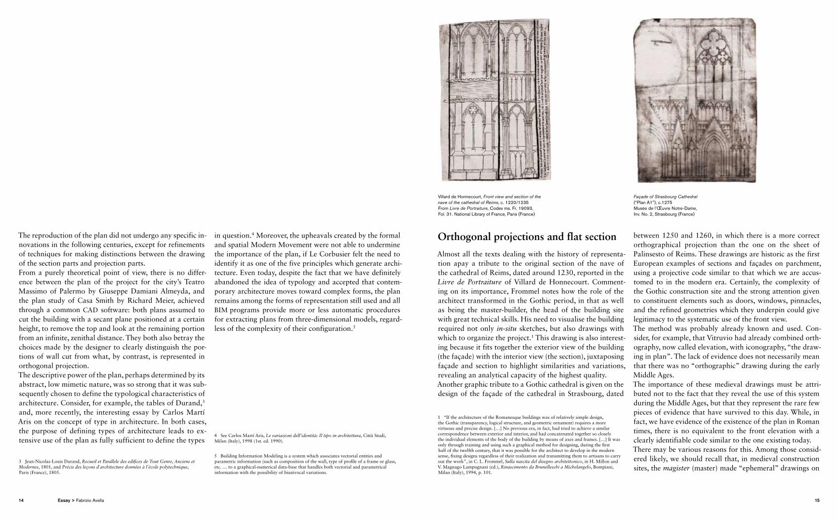
Almost all the texts dealing with the history of representation apay a tribute to the original section of the nave of the cathedral of Reims, dated around 1230, reported in the Livre de Portraiture of Villard de Honnecourt. Commenting on its importance, Frommel notes how the role of the architect transformed in the Gothic period, in that as well as being the masterbuilder, the head of the building site with great technical skills. His need to visualise the building required not only in-situ sketches, but also drawings with which to organize the project.1 This drawing is also interesting because it fits together the exterior view of the building (the façade) with the interior view (the section), juxtaposing façade and section to highlight similarities and variations, revealing an analytical cap acity of the highest quality.Another graphic tribute to a Gothic cathedral is given on the design of the façade of the cathedral in Strasbourg, dated
1 “If the architecture of the Romanesque buildings was of relatively simple design, the Gothic (transparency, logical structure, and geometric ornament) requires a more virtuous and precise design. […] No previous era, in fact, had tried to achieve a similar correspondence between exterior and interior, and had concatenated together so closely the individual elements of the body of the building by means of axes and frames. […] It was only through training and using such a graphical method for designing, during the first half of the twelfth century, that it was possible for the architect to develop in the modern sense, fixing designs regardless of their realization and transmitting them to artisans to carry out the work”, in C. L. Frommel, Sulla nascita del disegno architettonico, in H. Millon and V. Magnago Lampugnani (ed.), Rinascimento da Brunelleschi a Michelangelo, Bompiani, Milan (Italy), 1994, p. 101.
between 1250 and 1260, in which there is a more correct orthographical projection than the one on the sheet of Palinsesto of Reims. These drawings are historic as the first European examples of sections and façades on parchment, using a projective code similar to that which we are accustomed to in the modern era. Certainly, the complexity of the Gothic construction site and the strong attention given to constituent elements such as doors, windows, pinnacles, and the refined geometries which they underpin could give legitimacy to the systematic use of the front view.The method was probably already known and used. Consider, for example, that Vitruvio had already combined orthography, now called elevation, with iconography, “the drawing in plan”. The lack of evidence does not necessarily mean that there was no “ortho graphic” drawing during the early Middle Ages.The importance of these medieval drawings must be attributed not to the fact that they reveal the use of this system during the Middle Ages, but that they represent the rare few pieces of evidence that have survived to this day. While, in fact, we have evidence of the existence of the plan in Roman times, there is no equivalent to the front elevation with a clearly identifiable code similar to the one existing today.There may be various reasons for this. Among those considered likely, we should recall that, in medieval construction sites, the magister (master) made “ephemeral” drawings on
The reproduction of the plan did not undergo any specific innovations in the following centuries, except for refinements of techniques for making distinctions between the drawing of the section parts and projection parts.From a purely theoretical point of view, there is no difference between the plan of the project for the city’s Teatro Massimo of Palermo by Giuseppe Damiani Almeyda, and the plan study of Casa Smith by Richard Meier, achieved through a common CAD software: both plans assumed to cut the building with a secant plane positioned at a certain height, to remove the top and look at the remaining portion from an infinite, zenithal distance. They both also betray the choices made by the designer to clearly distinguish the portions of wall cut from what, by contrast, is represented in orthogonal projection.The descriptive power of the plan, perhaps determined by its abstract, low mimetic nature, was so strong that it was subsequently chosen to define the typological characteristics of architecture. Consider, for example, the tables of Durand,3 and, more recently, the interesting essay by Carlos Martí Aris on the concept of type in architecture. In both cases, the purpose of defining types of architecture leads to extensive use of the plan as fully sufficient to define the types
3 JeanNicolasLouis Durand, Recueil et Parallele des edifices de Tout Genre, Anciens et Modernes, 1801, and Précis des leçons d'architecture données à l’école polytechnique, Paris (France), 1805.
in question.4 Moreover, the upheavals created by the formal and spatial Modern Movement were not able to undermine the importance of the plan, if Le Corbusier felt the need to identify it as one of the five principles which generate architecture. Even today, despite the fact that we have definitely abandoned the idea of typology and accepted that contemporary architecture moves toward complex forms, the plan remains among the forms of representation still used and all BIM programs provide more or less automatic procedures for extracting plans from threedimensional models, regardless of the complexity of their configuration.5
4 See Carlos Martí Aris, Le variazioni dell’identità: Il tipo in architettura, Città Studi, Milan (Italy), 1998 (1st. ed. 1990).
5 Building Information Modeling is a system which associates vectorial entities and parametric information (such as composition of the wall, type of profile of a frame or glass, etc. … to a graphicalnumerical database that handles both vectorial and parametrical information with the possibility of biunivocal variations.
Villard de Honnecourt, Front view and section of the nave of the cathedral of Reims, c. 1220 /1235 From Livre de Portraiture, Codex ms. Fr. 19093, Fol. 31. National Library of France, Paris (France)
Façade of Strasbourg Cathedral (“Plan A1”), c.1275 Musée de l’Œuvre Notre-Dame, Inv. No. 2, Strasbourg (France)
14 15Essay > Fabrizio Avella
nondurable media, such as boards surrounded by wooden planks, where he would “draw” – or better rabble – with a steel or wooden stylus on a layer of lime. These drawings were actually an empirical tool for solving problems of implementation. They were necessary for the magister in order to communicate with apprentices. Once the problem was solved, the drawing could be removed and the “sheet” could be reused. The elevation drawing, like the plan, underwent a refinement during the Renaissance. One reason that may have played a role in this process lies in the education of the Renaissance architect, which included study through the survey of buildings, in order to infer compositional rules and codes. In painting the ancient building, little by little, orthogonal projection turned out to be even more effective, because it allowed the architectural order to be drawn and described with geometric al and impartial accuracy.If an architect begins to use a method of representation in order to understand ancient architecture, it is likely that he will also use it to think about the architecture to be built. Referring to specific essays on the role of drawing tools for developing architecture from the early Renaissance, it is useful to follow some of the steps.2 In the fifteenth century, the need to control the design process through drawing was already felt, and it is no coincidence that the
2 Please refer to W. Lotz, La rappresentazione degli interni nei disegni architettonici del Rinascimento, in Studi sull’architettura italiana del Rinascimento, Electa, Milan (Italy), 1989, (Original title Studies in the Italian Renaissance, Massachusetts 1977).
treatises devote space to specific thoughts on the methods of representation.In De re aedificatoria Leon Battista Alberti feels the need to give specific prescriptive guidance for architectural drawing that is intended for construction only, without yielding to the temptation of performing pictorial representations.3 The archi tect needs a metric precision that the painter does not and he must strive to design “the shape and extent of each front and each side using real angles and nonvariable lines: like one who wants his work to be judged not on a deceptive semblance, but precisely on the basis of verifiable measures”.4
In the early Renaissance, the perspective, despite its strong value for “measuring” space, was not used in architecture because it often produced an “illusory appearance” and for threedimensional representation wooden models were preferred, as they were indispensable tools for the verification of what was to be built, an important stage of the design process.
3 “The overall architecture consists of the drawing and construction. Concerning the drawing, its whole purpose and method is to find an exact and satisfactory way to fit together and connect lines and angles, through which the look of the building is fully defined. The function of the drawing is to assign to the buildings and their parts an appropriate location, an exact proportion, a convenient and harmonious order, so that the whole shape of the building rests entirely in the design itself.” [Author’s translation] In R. Bonelli and P. Portoghesi (eds.), Leon Battista Alberti, L’Architettura (De re aedificatoria), Book I [Il Disegno], Polifilo Edizioni, Milan (Italy), 1966, p. 18.
4 R. Bonelli and P. Portoghesi (eds.), Leon Battista Alberti, op. cit., Book II [materials], chap. I, p. 98. We recommend a comparison with the perspective method which Bramante used: A. Bruschi, Bramante, Laterza, Bari (Italy), 1990, I ed. Thames and Hudson, London (UK), 1973, pp. 13 – 32.
Thus, the model became in fact a method of representation,5 also praised by Leon Battista Alberti, who appreciates its metrical accuracy, to the point of considering its accuracy as one means of expenditure control: a sort of threedimensional cost estimate.6
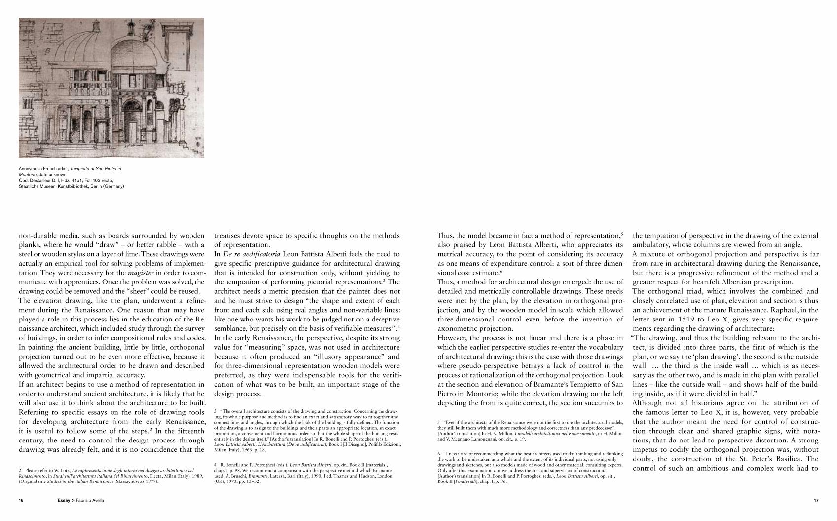
Thus, a method for architectural design emerged: the use of detailed and metrically controllable drawings. These needs were met by the plan, by the elevation in orthogonal projection, and by the wooden model in scale which allowed threedimensional control even before the invention of axon ometric projection.However, the process is not linear and there is a phase in which the earlier perspective studies reenter the vocabulary of architectural drawing: this is the case with those drawings where pseudoperspective betrays a lack of control in the process of rationalization of the orthogonal projection. Look at the section and elevation of Bramante’s Tempietto of San Pietro in Montorio; while the elevation drawing on the left depicting the front is quite correct, the section succumbs to
5 “Even if the architects of the Renaissance were not the first to use the architectural models, they still built them with much more methodology and correctness than any predecessor.” [Author’s translation] In H. A. Millon, I modelli architettonici nel Rinascimento, in H. Millon and V. Magnago Lampugnani, op. cit., p. 19.
6 “I never tire of recommending what the best architects used to do: thinking and rethinking the work to be undertaken as a whole and the extent of its individual parts, not using only drawings and sketches, but also models made of wood and other material, consulting experts. Only after this examination can we address the cost and supervision of construction.” [Author’s translation] In R. Bonelli and P. Portoghesi (eds.), Leon Battista Alberti, op. cit., Book II [I materiali], chap. I, p. 96.
the temptation of perspective in the drawing of the external ambulatory, whose columns are viewed from an angle.A mixture of orthogonal projection and perspective is far from rare in architectural drawing during the Renaissance, but there is a progressive refinement of the method and a greater respect for heartfelt Albertian prescription.The orthogonal triad, which involves the combined and closely correlated use of plan, elevation and section is thus an achievement of the mature Renaissance. Raphael, in the letter sent in 1519 to Leo X, gives very specific requirements regarding the drawing of architecture:
“The drawing, and thus the building relevant to the architect, is divided into three parts, the first of which is the plan, or we say the ‘plan drawing’, the second is the outside wall … the third is the inside wall … which is as necessary as the other two, and is made in the plan with parallel lines – like the outside wall – and shows half of the building inside, as if it were divided in half.” Although not all histor ians agree on the attribution of the famous letter to Leo X, it is, however, very probable that the author meant the need for control of construction through clear and shared graphic signs, with notations, that do not lead to perspective distortion. A strong impetus to codify the ortho gonal projection was, without doubt, the construction of the St. Peter’s Basilica. The control of such an ambitious and complex work had to
Anonymous French artist, Tempietto di San Pietro in Montorio, date unknown Cod. Destailleur D, I, Hdz. 4151, Fol. 103 recto, Staatliche Museen, Kunstbibliothek, Berlin (Germany)
16 17Essay > Fabrizio Avella
be supported by precise, metrically controllable graphics. The site, given the magnitude of the work, the design complexity and symbolic importance, was the perfect opportunity to codify the architectural drawing. Here, therefore, the requirement of the plan, of the “outside wall” and “inside wall”, is that of the elevation and of the section. The need was felt by Raphael, who grappled with the complexity of the work and who understood that he could not make use of perspective to address and solve the complex problems of the construction of St. Peter’s. The role played by Antonio da Sangallo the Younger in coding the section and the orthogonal projection is underlined by Wolfgang Lotz, who reminds us of his education as a “faber lignarius” (a carpenter): a nonphilosophical education which can be seen in Sangallo’s strength in implementing a drawing method more useful to a carpenter than a painter.7 He introduced (or reintroduced) it in the drawing of architecture with a dignity equal to that of perspective, which, while effectively describing space, is not ideal for metrically controlling the size of a
7 “The drawings we possess today, suggest that Antonio da Sangallo the Younger, the youngest apprentice of Raphael in the construction of the St. Peter Basilica, was the first to use orthogonal projections to represent an interior through the section.” [Author’s translation] In Wolfgang Lotz, Studies in Italian Renaissance Architecture, Cambridge, Massachusetts (USA), MIT Press, 1977, op. cit., p. 37.
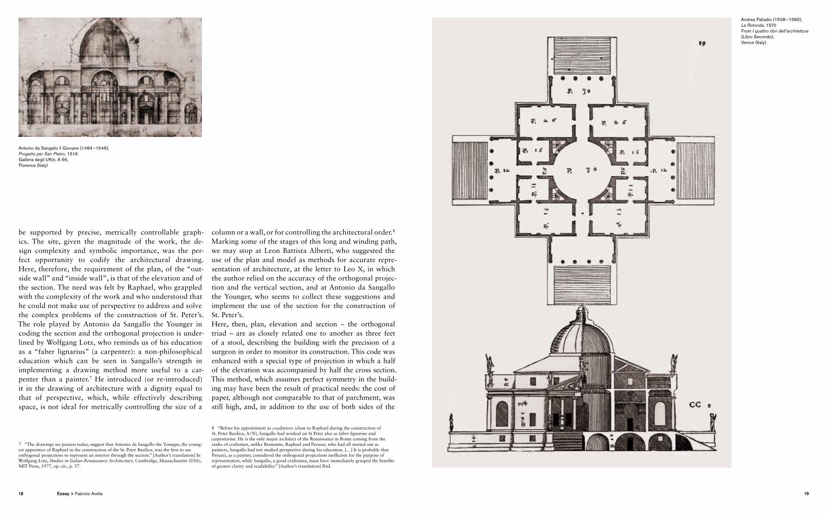
column or a wall, or for controlling the architectural order.8 Marking some of the stages of this long and winding path, we may stop at Leon Battista Alberti, who suggested the use of the plan and model as methods for accurate representation of architecture, at the letter to Leo X, in which the author relied on the accuracy of the orthogonal projection and the vertical section, and at Antonio da Sangallo the Younger, who seems to collect these suggestions and implement the use of the section for the construction of St. Peter’s.Here, then, plan, elevation and section – the orthogonal triad – are as closely related one to another as three feet of a stool, describing the building with the precision of a surgeon in order to monitor its construction. This code was enhanced with a special type of projection in which a half of the elevation was accompanied by half the cross section. This method, which assumes perfect symmetry in the building may have been the result of practical needs: the cost of paper, although not comparable to that of parchment, was still high, and, in addition to the use of both sides of the
8 “Before his appointment as coadjutore (close to Raphael during the construction of St. Peter Basilica, A / N), Sangallo had worked on St Peter also as faber lignarius and carpentarius. He is the only major architect of the Renaissance in Rome coming from the ranks of craftsmen, unlike Bramante, Raphael and Peruzzi, who had all started out as painters, Sangallo had not studied perspective during his education. […] It is probable that Peruzzi, as a painter, considered the orthogonal projections inefficient for the purpose of representation, while Sangallo, a good craftsman, must have immediately grasped the benefits of greater clarity and readability.” [Author’s translation] Ibid.
Antonio da Sangallo il Giovane (1484 –1546), Progetto per San Pietro, 1516 Galleria degli Uffizi, A 66, Florence (Italy)
Andrea Palladio (1508 –1580), La Rotonda, 1570 From I quattro libri dell’architettura (Libro Secondo), Venice (Italy)
18 19Essay > Fabrizio Avella
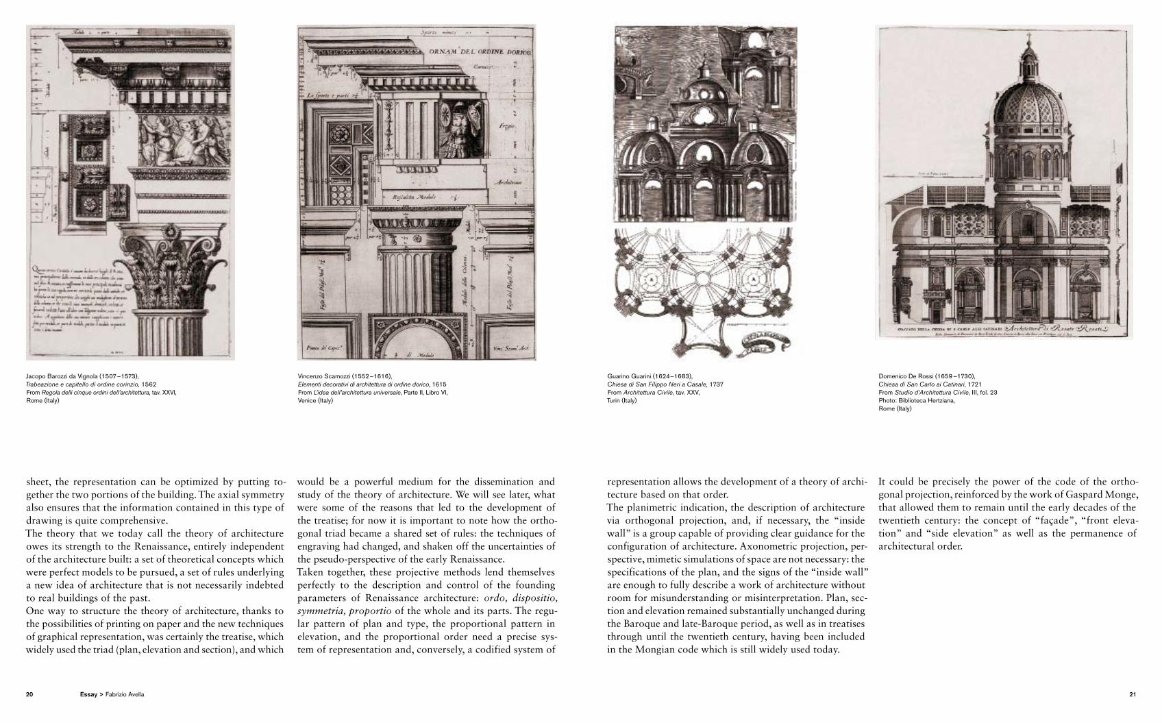
sheet, the representation can be optimized by putting together the two portions of the building. The axial sym metry also ensures that the information contained in this type of drawing is quite comprehensive.The theory that we today call the theory of architecture owes its strength to the Renaissance, entirely independent of the architecture built: a set of theoretical concepts which were perfect models to be pursued, a set of rules underlying a new idea of architecture that is not necessarily indebted to real buildings of the past. One way to structure the theory of architecture, thanks to the possibilities of printing on paper and the new techniques of graphical representation, was certainly the treatise, which widely used the triad (plan, elevation and section), and which
would be a powerful medium for the dissemination and study of the theory of architecture. We will see later, what were some of the reasons that led to the development of the treatise; for now it is important to note how the orthogonal triad became a shared set of rules: the techniques of engraving had changed, and shaken off the uncertainties of the pseudoperspective of the early Renaissance. Taken together, these projective methods lend themselves perfectly to the description and control of the founding parameters of Renaissance architecture: ordo, dispositio, symmetria, proportio of the whole and its parts. The regular pattern of plan and type, the proportional pattern in elevation, and the proportional order need a precise system of representation and, conversely, a codified system of
representation allows the development of a theory of architecture based on that order.The planimetric indication, the description of architecture via orthogonal projection, and, if necessary, the “inside wall” is a group capable of providing clear guidance for the configuration of architecture. Axonometric projection, perspective, mimetic simulations of space are not necessary: the specifications of the plan, and the signs of the “inside wall” are enough to fully describe a work of architecture without room for misunderstanding or misinterpretation. Plan, section and elevation remained substantially unchanged during the Baroque and lateBaroque period, as well as in treatises through until the twentieth century, having been included in the Mongian code which is still widely used today.
It could be precisely the power of the code of the orthogonal projection, reinforced by the work of Gaspard Monge, that allowed them to remain until the early decades of the twentieth century: the concept of “façade”, “front elevation” and “side elevation” as well as the permanence of architectural order.
Jacopo Barozzi da Vignola (1507 –1573), Trabeazione e capitello di ordine corinzio, 1562From Regola delli cinque ordini dell’architettura, tav. XXVI,Rome (Italy)
Vincenzo Scamozzi (1552 –1616), Elementi decorativi di architettura di ordine dorico, 1615From L’idea dell’architettura universale, Parte II, Libro VI, Venice (Italy)
Guarino Guarini (1624 –1683), Chiesa di San Filippo Neri a Casale, 1737From Architettura Civile, tav. XXV,Turin (Italy)
Domenico De Rossi (1659 –1730), Chiesa di San Carlo ai Catinari, 1721From Studio d‘Architettura Civile, III, fol. 23Photo: Biblioteca Hertziana, Rome (Italy)
20 21Essay > Fabrizio Avella
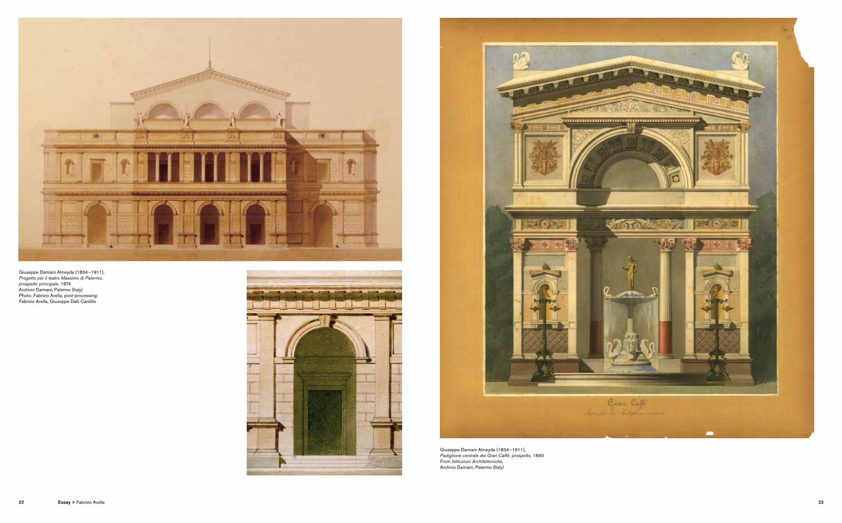
Giuseppe Damiani Almeyda (1834 –1911), Progetto per il teatro Massimo di Palermo, prospetto principale, 1874Archivio Damiani, Palermo (Italy) Photo: Fabrizio Avella, post-processing: Fabrizio Avella, Giuseppe Dalli Cardillo
Giuseppe Damiani Almeyda (1834 –1911), Padiglione centrale del Gran Caffé, prospetto, 1890 From Istituzioni Architettoniche, Archivio Damiani, Palermo (Italy)
22 23Essay > Fabrizio Avella
The “drawing, the outside wall and the inside wall” is therefore also a form of thought. Even the concept of the modern movement, based, however, on orthogonal planes, has not weakened this position: Le Corbusier felt the need to include the free plan among his five points and to control the Modulor in the elevation; the plan and the elevation lend themselves to “classicism” and the proportional severity of Mies van der Rohe.As far as the influence of the projection system on the thought of architecture is concerned, Vittorio Gregotti notes:
“As a first rough approximation we can say that the systems of repre sentation that we used are generally related to the structure of Euclidean space and its geometric representation for projections and sections, a system that has some significant limitations.” 9 The system of orthogonal projections, in fact, is able to re present architecture when it has certain characteristics: the façade of a Renaissance church is drawn on a plane parallel to the front, perpendicular to the main axis. The sections lie on vertical planes parallel to those of the elevations and any elevation belongs to planes which are all perpendicular to the plan. This system of projections reproduces (and inspires) features such as axiality and perpen-dicularity between axes and planes, referring to axes x, y, z,
9 V. Gregotti, I materiali dell’architettura, Feltrinelli, Milan (Italy), 1966, pp. 28–29. [Author’s translation]
which are orthogonal to each other. These features, though within complex space systems, have remained in many examples of modern and contemporary architecture. The spatial, formal and volumetric complexity of the emblematic architecture of the twentieth century from Rietveld to Loos, from Mies to Meier is, however, to be considered as a highly structured system of orthogonal planes. As far as digital design is concerned, nothing new was introduced, apart from a procedural point of view: the elevation is not a drawing to be attached to the plan, which generates the information needed for its construction, but is one of the infinite elaborations that can be drawn from a threedimensional model. It is a twodimensional set of threedimensional information. It can be realized as an autonomous twodimensional model, but the tendency is to cut it from a threedimensional model and submit it to a subsequent postprocessing, where information can be added, such as dimensions, notations or other technical information.Fabrizio Avella,
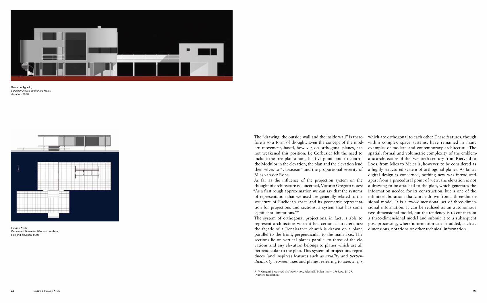
Farnsworth House by Mies van der Rohe, plan and elevation, 2006
Bernardo Agnello, Saltzman House by Richard Meier, elevation, 2006
24 25Essay > Fabrizio Avella
P
Perspective
Anyone wishing to find out the genesis of perspective can draw on essays of unsurpassed completeness: from the now “classic” essay by Erwin Panofski Perspective as Sym-bolic Form,1 to the most recent work by Martin Kemp, The Science of Art,2 to Henry Millon and Vittorio Lampugnani Magnago’s, Rinascimento da Brunelleschi a Michelangelo. La rappresentazione dell’architettura,3 to name only the most famous. Beyond the various approaches of the works cited and other essays on the topic, it seems that today we can agree on some points. First of all, as we have seen for orthogonal projections, the perspective that we know today is the result of a long process of codification, which had a strong push in the early fifteenth century. This is not to say that it did not exist previously: Panofsky points out that every era had its own perspective, a system to represent the depth of space. From the vertical axis perspective
1 Erwin Panofsky, La prospettiva come forma simbolica, Feltrinelli, Milan (Italy), 1995, [original title: Die Perspektive als “symbolische Form”, Leipzig – Berlin 1927] I ed. it. Milan (Italy) 1961.
2 Martin Kemp, La scienza dell’arte, Prospettiva e percezione visiva da Brunelleschi a Seurat, Gruppo Editoriale Giunti, Florence (Italy), 1994 [original title: The Science of Art: Optical Themes in Western Art from Brunelleschi to Seurat, Yale University Press, 1990].
3 Henry Millon, Vittorio Magnago Lampugnani (ed.), Rinascimento da Brunelleschi a Michelangelo. La rappresentazione dell’architettura, Bompiani, Milan (Italy), 1994.
with “fish bone” vanishing point perspective, to the mere juxtaposition of an array of Byzantine plans, sufficient to understand what is “in front” and what is “behind”, each era chose its own way of representing space. Even masters of painting such as Giotto and Lorenzetti, had begun to explore different ways to represent the volume and placement of figures in the depths of space, to overcome the long standing problem of the representation of the n dimensions of phenomenal reality on the two dimensions of the surface to be painted. The interest in perspective was very strong both in the pictorial as well as architectural fields and the two areas overlapped in the fifteenth century, and lost their disciplinary boundaries: it is not clear whether the perspective was borrowed from pictorial studies or if the pictorial painting absorbed a method developed to draw a rational space like that of the Renaissance. Early studies on the definition of a method can be seen in the work of one architect, Filippo Brunelleschi, who, in 1413, drew on a board the famous Baptistery of Florence; Leon Battista Alberti wrote about the perspective in De Pictura of 1436, to emphasize the fact that perspective does not belong to architectural design. The ideal city of Baltimora is dated after 1470, but it would be questionable if it is a framework or an architectural representation. De prospectiva pingendi by Piero della Francesca was produced in 1482, during his stay in Rimini, after completion of his major paintings, which are
often framed in architectural spaces, and, in the same year, the presence of Donato Bramante in Milan is documented for the construction of the choir of Santa Maria in San Satiro, which thanks to a perspective was able to simulate a depth similar to that of the transepts, deceptively expanding a space that was, in fact, relatively small.One could continue at length, but simply to highlight some aspects: the perspectiva artificialis4 focuses on the positioning of a point of view from a measurable distance, coinciding with the eye of the observer, from which the visual rays start and, intersected by a plane, give life to the representation of perspective. Point of view (V), projected perpendicular to the framework, determines the position of principal point (P), i.e. the vanishing point of lines perpendicular to the plane. Studies by Brunelleschi, the method of L. B. Alberti (“Intersection of the visual pyramid”), the experiments of Albrecht Dürer, the optical chamber of Canaletto, are all based on the same concept: given a centre of projection, the image of infinite points in space can be determined if, interposing a plane between this centre and objects in space, it is possible to draw (on the plane) the intersection between the plane and the “pyramid” of visual rays. Hoping not
4 Thus defined to distinguish it from the perspectiva naturalis, which concerned the technique to render the depth of natural landscapes. Note in this regard Leonardo’s theory that required to lighten the hills and decrease the saturation of colour as we move away from the representation framework.
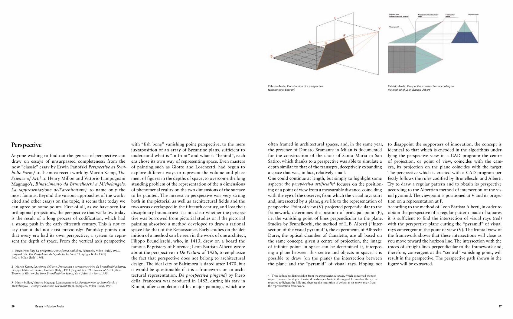
to disappoint the supporters of innovation, the concept is identical to that which is encoded in the algorithms underlying the perspective view in a CAD program: the centre of projection, or point of view, coincides with the camera, its projection on the plane coincides with the target. The perspective which is created with a CAD program perfectly follows the rules codified by Brunelleschi and Alberti. Try to draw a regular pattern and to obtain its perspective according to the Albertian method of intersection of the visual pyramid. The viewpoint is positioned at V and its projection on a representation at P.According to the method of Leon Battista Alberti, in order to obtain the perspective of a regular pattern made of squares it is sufficient to find the intersection of visual rays (red) with the perspective plane cutting the “pyramid” of visual rays convergent in the point of view (V). The frontal view of the framework shows that these intersections will close as you move toward the horizon line. The intersection with the traces of straight lines perpendicular to the framework and, therefore, convergent at the “central” vanishing point, will result in the perspective. The perspective path shown in the figure will be extracted.
Fabrizio Avella, Construction of a perspective (axonometric diagram)
Fabrizio Avella, Perspective construction according to the method of Leon Battista Alberti
26 27Essay > Fabrizio Avella
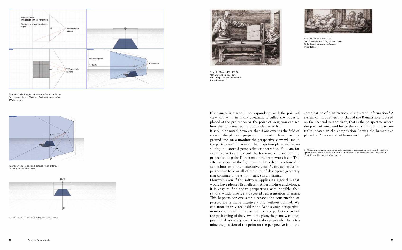
If a camera is placed in correspondence with the point of view and what in many programs is called the target is placed at the projection on the point of view, you can see how the two constructions coincide perfectly.It should be noted, however, that if one extends the field of view of the plane of projection, marked in blue, over the ground line, on a monitor the perspective view will make the parts placed in front of the projection plane visible, resulting in distorted perspective or aberration. You can, for example, vertically extend the framework to include the projection of point D in front of the framework itself. The effect is shown in the figure, where D' is the projection of D at the bottom of the perspective view. Again, construction perspective follows all of the rules of descriptive geometry that continue to have importance and meaning.However, even if the software applies an algorithm that would have pleased Brunelleschi, Alberti, Dürer and Monge, it is easy to find today perspectives with horrible aberrations which provide a distorted representation of space. This happens for one simple reason: the construction of perspective is made intuitively and without control. We can momentarily reconsider the Renaissance perspective: in order to draw it, it is essential to have perfect control of the positioning of the view in the plan, the plane was often positioned vertically and it was always possible to determine the position of the point on the perspective from the
combination of planimetric and altimetric information.5 A system of thought such as that of the Renaissance focused on the “central perspective”, that is the perspective where the point of view, and hence the vanishing point, was centrally located in the composition. It was the human eye, placed on “the centre” of humanist thought.
5 Not considering, for the moment, the perspective construction performed by means of optical rooms or other tools. For the use of auxiliary tools for mechanical construction, cf. M. Kemp, The Science of Art, op. cit.
Fabrizio Avella, Perspective scheme which extends the width of the visual field
Fabrizio Avella, Perspective of the previous scheme
Albrecht Dürer (1471–1528), Man Drawing a Lute, 1525 Bibliothèque Nationale de France,Paris (France)
Albrecht Dürer (1471–1528), Man Drawing a Reclining Woman, 1525 Bibliothèque Nationale de France,Paris (France)
Fabrizio Avella, Perspective construction according to the method of Leon Battista Alberti performed with a CAD software
28 29Essay > Fabrizio Avella
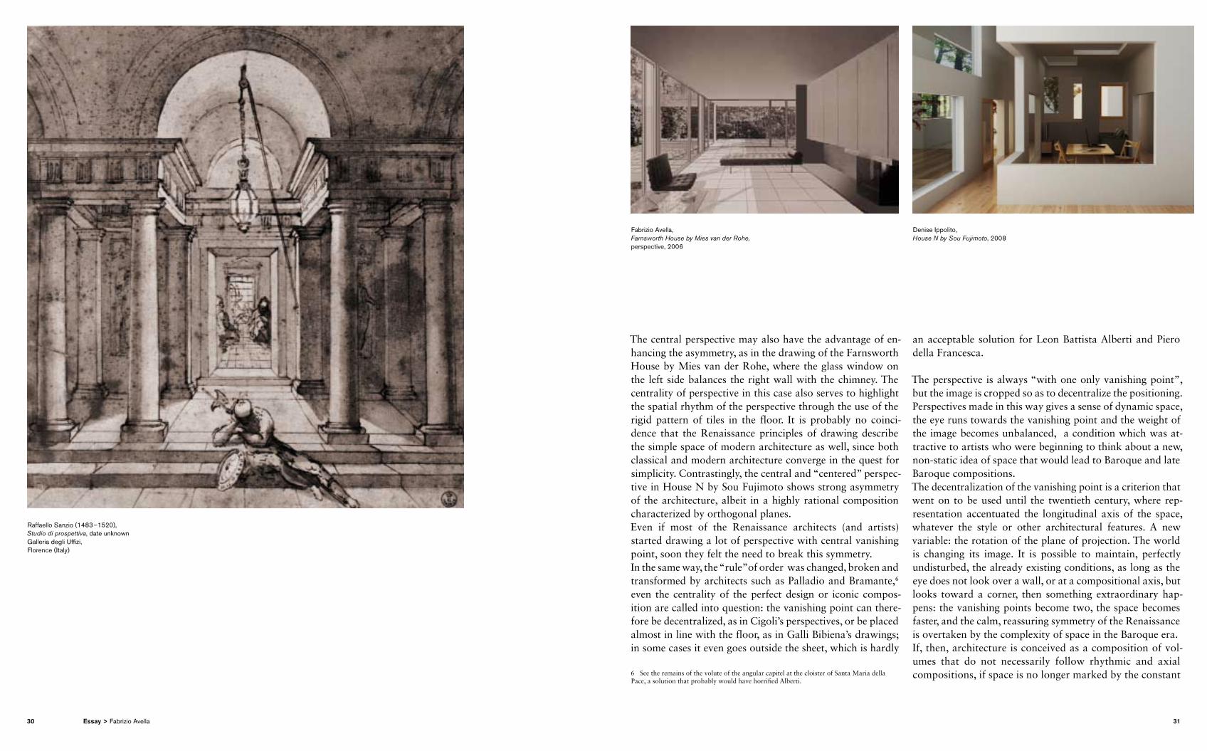
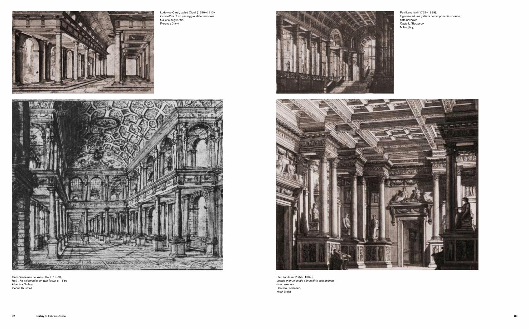
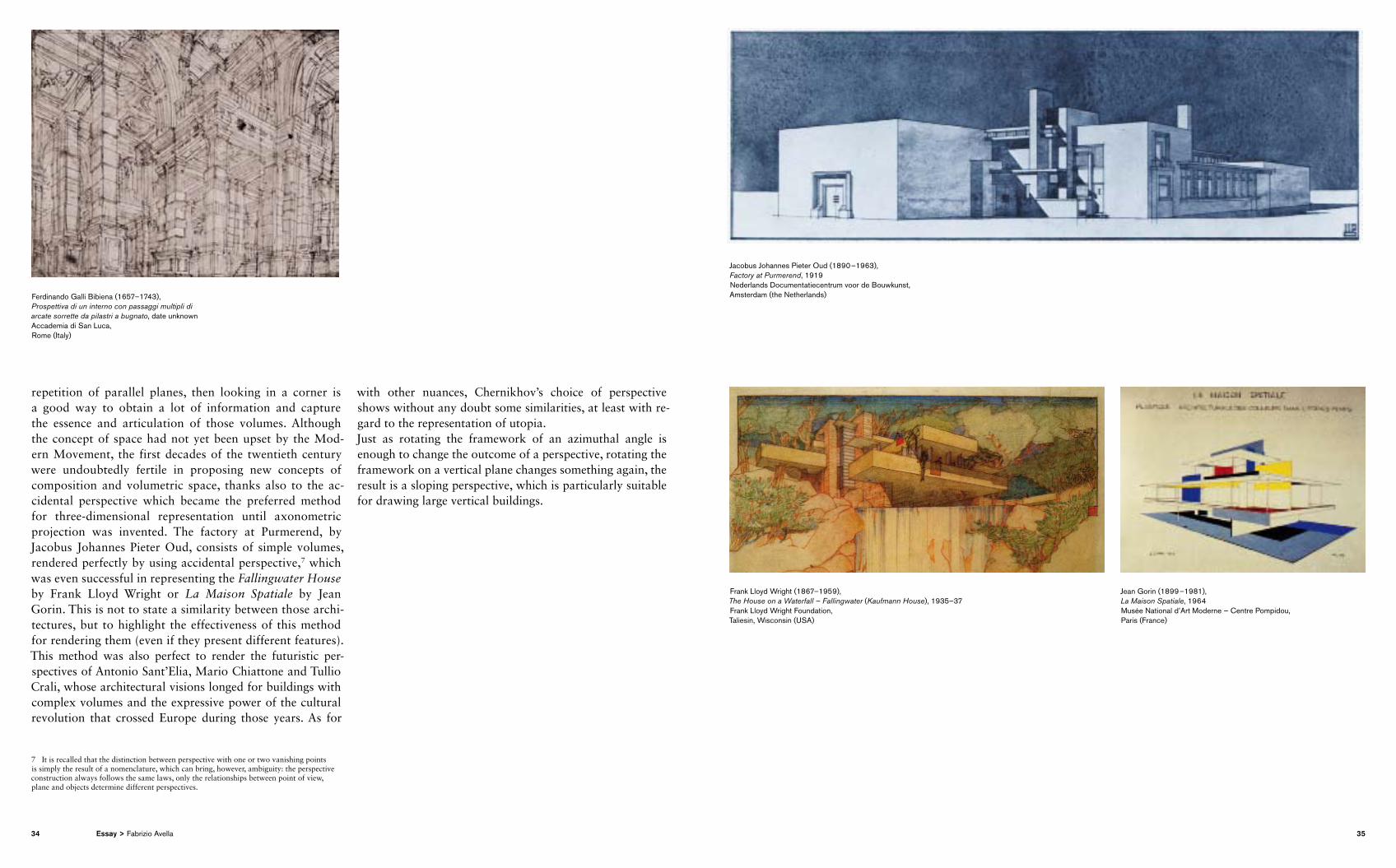
The central perspective may also have the advantage of enhancing the asymmetry, as in the drawing of the Farnsworth House by Mies van der Rohe, where the glass window on the left side balances the right wall with the chimney. The centrality of perspective in this case also serves to highlight the spatial rhythm of the perspective through the use of the rigid pattern of tiles in the floor. It is probably no coincidence that the Renaissance principles of drawing describe the simple space of modern architecture as well, since both classical and modern architecture converge in the quest for simplicity. Contrastingly, the central and “centered” perspective in House N by Sou Fujimoto shows strong asymmetry of the architecture, albeit in a highly rational composition characterized by orthogonal planes. Even if most of the Renaissance architects (and artists) started drawing a lot of perspective with central vanishing point, soon they felt the need to break this symmetry. In the same way, the “rule”of order was changed, broken and transformed by architects such as Palladio and Bramante,6 even the centrality of the perfect design or iconic composition are called into question: the vanishing point can therefore be decentralized, as in Cigoli’s perspectives, or be placed almost in line with the floor, as in Galli Bibiena’s drawings; in some cases it even goes outside the sheet, which is hardly
6 See the remains of the volute of the angular capitel at the cloister of Santa Maria della Pace, a solution that probably would have horrified Alberti.
an acceptable solution for Leon Battista Alberti and Piero della Francesca.
The perspective is always “with one only vanishing point”, but the image is cropped so as to decentralize the positioning. Perspectives made in this way gives a sense of dynamic space, the eye runs towards the vanishing point and the weight of the image becomes unbalanced, a condition which was attractive to artists who were beginning to think about a new, nonstatic idea of space that would lead to Baroque and late Baroque compositions.The decentralization of the vanishing point is a criterion that went on to be used until the twentieth century, where representation accentuated the longitudinal axis of the space, whatever the style or other architectural features. A new variable: the rotation of the plane of projection. The world is changing its image. It is possible to maintain, perfectly undisturbed, the already existing conditions, as long as the eye does not look over a wall, or at a compositional axis, but looks toward a corner, then something extraordin ary happens: the vanishing points become two, the space becomes faster, and the calm, reassuring symmetry of the Renaissance is overtaken by the complexity of space in the Baroque era.If, then, architecture is conceived as a composition of volumes that do not necessarily follow rhythmic and axial compositions, if space is no longer marked by the constant
Raffaello Sanzio (1483 –1520), Studio di prospettiva, date unknown Galleria degli Uffizi, Florence (Italy)
Fabrizio Avella, Farnsworth House by Mies van der Rohe, perspective, 2006
Denise Ippolito, House N by Sou Fujimoto, 2008
30 31Essay > Fabrizio Avella
Ludovico Cardi, called Cigoli (1559 –1613), Prospettiva di un passaggio, date unknown Galleria degli Uffizi,Florence (Italy)
Hans Vredeman de Vries (1527 –1609), Hall with colonnades on two floors, c. 1560 Albertina Gallery, Vienna (Austria)
Paul Landriani (1755 –1839), Ingresso ad una galleria con imponente scalone, date unknown Castello Sforzesco, Milan (Italy)
Paul Landriani (1755 –1839), Interno monumentale con soffitto cassettonato, date unknown Castello Sforzesco, Milan (Italy)
32 33Essay > Fabrizio Avella
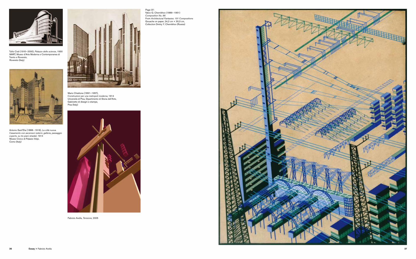
repetition of parallel planes, then looking in a corner is a good way to obtain a lot of information and capture the essence and articulation of those volumes. Although the concept of space had not yet been upset by the Modern Movement, the first decades of the twentieth century were undoubtedly fertile in proposing new concepts of com position and volumetric space, thanks also to the accidental perspective which became the preferred method for threedimensional representation until axonometric projection was invented. The factory at Purmerend, by Jacobus Johannes Pieter Oud, consists of simple volumes, rendered perfectly by using accidental perspective,7 which was even successful in representing the Fallingwater House by Frank Lloyd Wright or La Maison Spatiale by Jean Gorin. This is not to state a similarity between those architectures, but to highlight the effectiveness of this method for rendering them (even if they present different features). This method was also perfect to render the futuristic perspectives of Antonio Sant’Elia, Mario Chiattone and Tullio Crali, whose architectural visions longed for buildings with complex volumes and the expressive power of the cultural revolution that crossed Europe during those years. As for
7 It is recalled that the distinction between perspective with one or two vanishing points is simply the result of a nomenclature, which can bring, however, ambiguity: the perspective construction always follows the same laws, only the relationships between point of view, plane and objects determine different perspectives.
with other nuances, Chernikhov’s choice of perspective shows without any doubt some similarities, at least with regard to the representation of utopia.Just as rotating the framework of an azimuthal angle is enough to change the outcome of a perspective, rotating the framework on a vertical plane changes something again, the result is a sloping perspective, which is particularly suitable for drawing large vertical buildings.
Ferdinando Galli Bibiena (1657–1743), Prospettiva di un interno con passaggi multipli di arcate sorrette da pilastri a bugnato, date unknown Accademia di San Luca, Rome (Italy)
Jacobus Johannes Pieter Oud (1890 –1963), Factory at Purmerend, 1919 Nederlands Documentatiecentrum voor de Bouwkunst, Amsterdam (the Netherlands)
Frank Lloyd Wright (1867–1959), The House on a Waterfall – Fallingwater (Kaufmann House), 1935–37 Frank Lloyd Wright Foundation,Taliesin, Wisconsin (USA)
Jean Gorin (1899 –1981), La Maison Spatiale, 1964 Musée National d’Art Moderne – Centre Pompidou,Paris (France)
34 35Essay > Fabrizio Avella
Tullio Crali (1910 – 2000), Palazzo delle scienze, 1930 MART, Museo d’Arte Moderna e Contemporanea di Trento e Rovereto, Rovereto (Italy)
Antonio Sant’Elia (1888 – 1916), La città nuova. Casamento con ascensori esterni, galleria, passaggio coperto, su tre piani stradali, 1914 Museo Civico di Palazzo Volpi, Como (Italy)
Mario Chiattone (1891– 1957), Construzioni per una metropoli moderna, 1914 Università di Pisa, Dipartimento di Storia dell’Arte, Gabinetto di disegni e stampe, Pisa (Italy)
Fabrizio Avella, Tensione, 2005
Page 37:Yakov G. Chernikhov (1889 –1951) Composition No. 86From Architectural Fantasies: 101 Compositions Gouache on paper, 24,2 cm × 30,3 cm, Collection Dmitry Y. Chernikhov (Russia)
36 37Essay > Fabrizio Avella
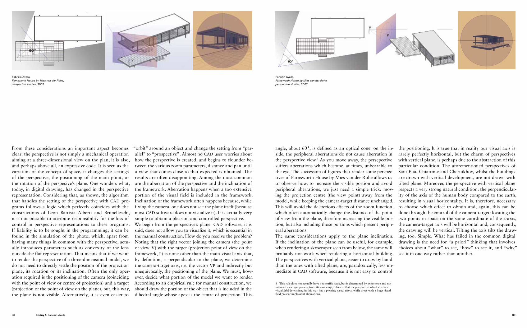
From these considerations an important aspect becomes clear: the perspective is not simply a mechanical operation aiming at a threedimensional view on the plan, it is also, and perhaps above all, an expressive code. It is seen as the variation of the concept of space, it changes the settings of the perspective, the positioning of the main point, or the rotation of the perspecive’s plane. One wonders what, today, in digital drawing, has changed in the perspective representation. Considering that, as shown, the algorithm that handles the setting of the perspective with CAD programs follows a logic which perfectly coincides with the constructions of Leon Battista Alberti and Brunelleschi, it is not possible to attribute responsibility for the loss of control in perspective representations to these programs. If liability is to be sought in the programming, it can be found in the simulation of the photo, which, apart from having many things in common with the perspective, actually introduces parameters such as convexity of the lens outside the flat representation. That means that if we want to render the perspective of a threedimensional model, we do not need to directly settle the pos ition of the projection plane, its rotation or its inclin ation. Often the only operation required is the positioning of the camera (coinciding with the point of view or centre of projection) and a target (projection of the point of view on the plane), but, this way, the plane is not visible. Alternatively, it is even easier to
“orbit” around an object and change the setting from “parallel” to “prospective”. Almost no CAD user worries about how the perspective is created, and begins to flounder between the various zoom parameters, distance and pan until a view that comes close to that expected is obtained. The results are often disappointing. Among the most common are the aberration of the perspective and the inclination of the framework. Aberration happens when a too extensive portion of the visual field is included in the framework. Inclination of the framework often happens because, while fixing the camera, one does not see the plane itself (because most CAD software does not visualize it). It is actually very simple to obtain a pleasant and controlled perspective. We begin from the perspective’s plane: CAD software, it is said, does not allow you to visualize it, which is essential in the manual construction. How do you resolve the problem? Noting that the right vector joining the camera (the point of view, V) with the target (projection point of view on the framework, P) is none other than the main visual axis that, by definition, is perpendicular to the plane, we determine the cameratarget axis, i. e. the vector VP and indirectly but unequivocally, the positioning of the plane. We must, however, decide what portion of the model we want to render. According to an empirical rule for manual construction, we should draw the portion of the object that is included in the dihedral angle whose apex is the centre of projection. This
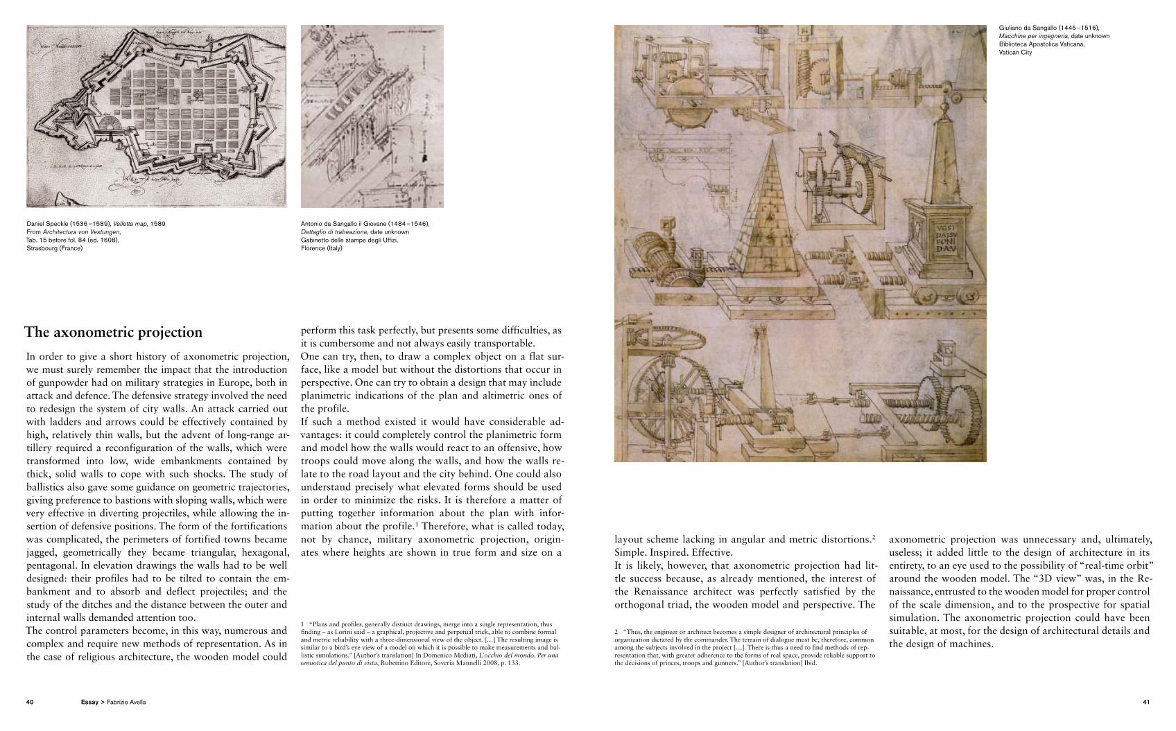
angle, about 60 °, is defined as an optical cone: on the inside, the peripheral aberrations do not cause aberration in the perspective view.8 As you move away, the persepective suffers aberrations which become, at times, unbearable to the eye. The succession of figures that render some perspectives of Farnsworth House by Mies van der Rohe allows us to observe how, to increase the visible portion and avoid peripheral aberrations, we just need a simple trick: moving the projection centre (the view point) away from the model, while keeping the cameratarget distance unchanged. This will avoid the deleterious effects of the zoom function, which often automatically change the distance of the point of view from the plane, therefore increasing the visible portion, but also including those portions which present peripheral aberrations.The same considerations apply to the plane inclination. If the inclination of the plane can be useful, for example, when rendering a skyscraper seen from below, the same will probably not work when rendering a horizontal building. The perspectives with vertical plane, easier to draw by hand than the ones with tilted plane, are, paradoxically, less immediate in CAD software, because it is not easy to control
8 This rule does not actually have a scientific basis, but is determined by experience and not intended as a rigid prescription. We can simply observe that the perspective which covers a visual field determined in this way has a pleasing visual effect, while those with a huge visual field present unpleasant aberrations.
the pos itioning. It is true that in reality our visual axis is rarely perfectly horizontal, but the charm of perspectives with vertical plane, is perhaps due to the abstraction of this particular condition. The aforementioned perspectives of Sant’Elia, Chiattone and Chernikhov, whilst the buildings are drawn with vertical development, are not drawn with tilted plane. Moreover, the perspective with vertical plane respects a very strong natural condition: the perpendicularity of the axis of the human body compared to the earth, resulting in visual horizontality. It is, therefore, necessary to choose which effect to obtain and, again, this can be done through the control of the cameratarget: locating the two points in space on the same coordinate of the zaxis, the cameratarget axis will be horizontal and, consequently, the drawing will be vertical. Tilting the axis tilts the drawing, too. Simple. What has failed in the common digit al drawing is the need for “a priori” thinking that involves choices about “what” to see, “how” to see it, and “why” see it in one way rather than another.
Fabrizio Avella, Farnsworth House by Mies van der Rohe, perspective studies, 2007
Fabrizio Avella, Farnsworth House by Mies van der Rohe, perspective studies, 2007
38 39Essay > Fabrizio Avella
The axonometric projection In order to give a short history of axonometric projection, we must surely remember the impact that the introduction of gunpowder had on military strategies in Europe, both in attack and defence. The defensive strategy involved the need to redesign the system of city walls. An attack carried out with ladders and arrows could be effectively contained by high, relatively thin walls, but the advent of longrange artillery required a reconfiguration of the walls, which were transformed into low, wide embankments contained by thick, solid walls to cope with such shocks. The study of ballistics also gave some guidance on geometric trajec tories, giving preference to bastions with sloping walls, which were very effective in diverting projectiles, while allowing the insertion of defensive positions. The form of the fortifications was complicated, the perimeters of fortified towns became jagged, geometrically they became triangular, hexagonal, pentagonal. In elevation drawings the walls had to be well designed: their profiles had to be tilted to contain the embankment and to absorb and deflect projectiles; and the study of the ditches and the distance between the outer and internal walls demanded attention too.The control parameters become, in this way, numerous and complex and require new methods of representation. As in the case of religious architecture, the wooden model could
perform this task perfectly, but presents some difficulties, as it is cumbersome and not always easily transportable.One can try, then, to draw a complex object on a flat surface, like a model but without the distortions that occur in perspective. One can try to obtain a design that may include planimetric indications of the plan and altimetric ones of the profile.If such a method existed it would have considerable advantages: it could completely control the planimetric form and model how the walls would react to an offensive, how troops could move along the walls, and how the walls relate to the road layout and the city behind. One could also understand precisely what elevated forms should be used in order to minimize the risks. It is therefore a matter of putting together information about the plan with information about the profile.1 Therefore, what is called today, not by chance, military axonometric projection, originates where heights are shown in true form and size on a
1 “Plans and profiles, generally distinct drawings, merge into a single representation, thus finding – as Lorini said – a graphical, projective and perpetual trick, able to combine formal and metric reliability with a threedimensional view of the object. […] The resulting image is similar to a bird’s eye view of a model on which it is possible to make measurements and ballistic simulations.” [Author’s translation] In Domenico Mediati, L’occhio del mondo. Per una semiotica del punto di vista, Rubettino Editore, Soveria Mannelli 2008, p. 133.
layout scheme lacking in angular and metric distortions.2 Simple. Inspired. Effective.It is likely, however, that axonometric projection had little success because, as already mentioned, the interest of the Renaissance architect was perfectly satisfied by the orthogonal triad, the wooden model and perspective. The
2 “Thus, the engineer or architect becomes a simple designer of architectural principles of organization dictated by the commander. The terrain of dialogue must be, therefore, common among the subjects involved in the project […]. There is thus a need to find methods of representation that, with greater adherence to the forms of real space, provide reliable support to the decisions of princes, troops and gunners.” [Author’s translation] Ibid.
axonometric projection was unnecessary and, ultimately, useless; it added little to the design of architecture in its entirety, to an eye used to the possibility of “realtime orbit” around the wooden model. The “3D view” was, in the Renaissance, entrusted to the wooden model for proper control of the scale dimension, and to the prospective for spatial simulation. The axonometric projection could have been suitable, at most, for the design of architectural details and the design of machines.
Daniel Speckle (1536 –1589), Valletta map, 1589 From Architectura von Vestungen, Tab. 15 before fol. 84 (ed. 1608),Strasbourg (France)
Antonio da Sangallo il Giovane (1484 –1546), Dettaglio di trabeazione, date unknown Gabinetto delle stampe degli Uffizi, Florence (Italy)
Giuliano da Sangallo (1445 –1516), Macchine per ingegneria, date unknown Biblioteca Apostolica Vaticana, Vatican City
40 41Essay > Fabrizio Avella
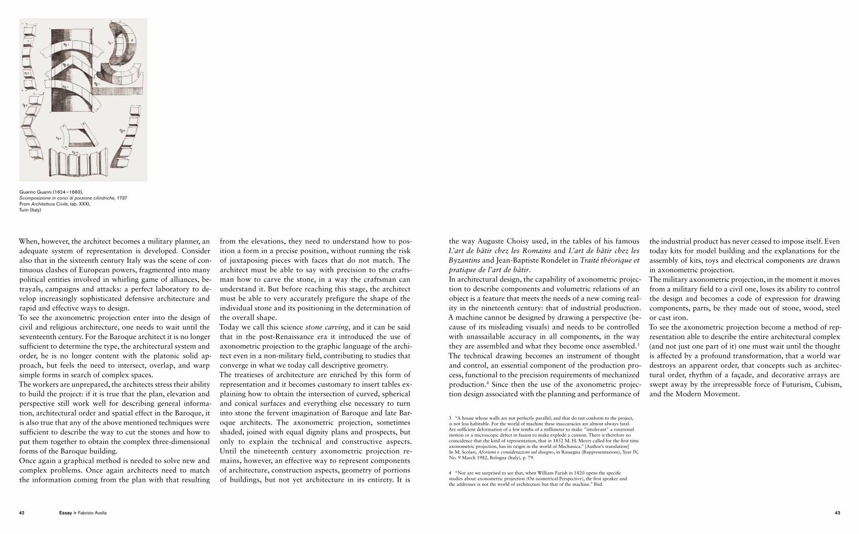
When, however, the architect becomes a military planner, an adequate system of representation is developed. Consider also that in the sixteenth century Italy was the scene of continuous clashes of European powers, fragmented into many political entities involved in whirling game of alliances, betrayals, campaigns and attacks: a perfect laboratory to develop increasingly sophisticated defensive architecture and rapid and effective ways to design. To see the axonometric projection enter into the design of civil and religious architecture, one needs to wait until the seventeenth century. For the Baroque architect it is no longer sufficient to determine the type, the architectural system and order, he is no longer content with the platonic solid approach, but feels the need to intersect, overlap, and warp simple forms in search of complex spaces.The workers are unprepared, the architects stress their ability to build the project: if it is true that the plan, elevation and perspective still work well for describing general information, architectural order and spatial effect in the Baroque, it is also true that any of the above mentioned techniques were sufficient to describe the way to cut the stones and how to put them together to obtain the complex threedimensional forms of the Baroque building.Once again a graphical method is needed to solve new and complex problems. Once again architects need to match the information coming from the plan with that resulting
from the elevations, they need to understand how to position a form in a precise position, without running the risk of juxtaposing pieces with faces that do not match. The architect must be able to say with precision to the craftsman how to carve the stone, in a way the craftsman can understand it. But before reaching this stage, the architect must be able to very accurately prefigure the shape of the individual stone and its positioning in the determination of the overall shape.Today we call this science stone carving, and it can be said that in the postRenaissance era it introduced the use of axon ometric projection to the graphic language of the architect even in a nonmilitary field, contributing to studies that converge in what we today call descriptive geometry.The treatieses of architecture are enriched by this form of representation and it becomes customary to insert tables explaining how to obtain the intersection of curved, spherical and conical surfaces and everything else necessary to turn into stone the fervent imagination of Baroque and late Baroque architects. The axonometric projection, sometimes shaded, joined with equal dignity plans and prospects, but only to explain the technical and constructive aspects. Until the nineteenth century axonometric projection remains, however, an effective way to represent components of architecture, construction aspects, geometry of portions of buildings, but not yet architecture in its entirety. It is
the way Auguste Choisy used, in the tables of his famous L’art de bâtir chez les Romains and L’art de bâtir chez les Byzantins and JeanBaptiste Rondelet in Traité théorique et pratique de l’art de bâtir. In architectural design, the capability of axonometric projection to describe components and volumetric relations of an object is a feature that meets the needs of a new coming reality in the nineteenth century: that of industrial production. A machine cannot be designed by drawing a perspective (because of its misleading visuals) and needs to be controlled with unassailable accuracy in all components, in the way they are assembled and what they become once assembled.3 The technical drawing becomes an instrument of thought and control, an essential component of the production process, functional to the precision requirements of mechanized production.4 Since then the use of the axonometric projection design associated with the planning and performance of
3 “A house whose walls are not perfectly parallel, and that do not conform to the project, is not less habitable. For the world of machine these inaccuracies are almost always fatal. Are sufficient deformation of a few tenths of a millimeter to make "intolerant" a rotational motion or a microscopic defect in fusion to make explode a cannon. There is therefore no coincidence that the kind of representation, that in 1852 M. H. Meyer called for the first time axonometric projection, has its origin in the world of Mechanica.” [Author’s translation] In M. Scolari, Aforismi e considerazioni sul disegno, in Rassegna (Rappresentazioni), Year IV, No. 9 March 1982, Bologna (Italy), p. 79.
4 “Nor are we surprised to see that, when William Farish in 1820 opens the specific studies about axonometric projection (On isometrical Perspective), the first speaker and the addressee is not the world of architecture but that of the machine.” Ibid.
the industrial product has never ceased to impose itself. Even today kits for model building and the explanations for the assembly of kits, toys and electrical components are drawn in axonometric projection.The military axonometric projection, in the moment it moves from a military field to a civil one, loses its ability to control the design and becomes a code of expression for drawing components, parts, be they made out of stone, wood, steel or cast iron.To see the axonometric projection become a method of representation able to describe the entire architectural complex (and not just one part of it) one must wait until the thought is affected by a profound transformation, that a world war destroys an apparent order, that concepts such as architectural order, rhythm of a façade, and decorative arrays are swept away by the irrepressible force of Futurism, Cubism, and the Modern Movement.
Guarino Guarini (1624 –1683), Scomposizione in conci di porzione cilindriche, 1737From Architettura Civile, tab. XXXI, Turin (Italy)
42 43Essay > Fabrizio Avella
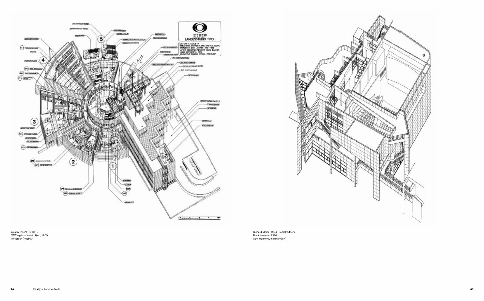
Gustav Peichl (1928 –), ORF regional studio Tyrol, 1969 Innsbruck (Austria)
Richard Meier (1934 –) and Partners, The Atheneum, 1976New Harmony, Indiana (USA)
44 45Essay > Fabrizio Avella
Everything is called into question politically: democracy, economic growth, visual arts, literary patterns. The point of view and perspective disappear from painting. Pictorial space is no longer measurable. Architectural order is banished: it is not appropriate in a world that seems to reject the order of things. It seems, moreover, that after fanciful interpretations made by architects and imitators from the Renaissance onwards, it had used up its expressive and significant strength. The beginning of the twentieth century presented fertile ground for the displacing of axonometric projection from the design of machines to that of architecture. This occured for several reasons: in the Modern Movement, architecture is considered a “living machine”. If I have to draw a car, I need a method already successfully tested in the design of machines. Modern architecture rejects “style”, order, decor ation, façade,5 in favour of a concept of space and form that tends to trap, intersect, split simple volumes, collecting the pieces in new compositions and reassembling
5 “The supremacy of the façade, so the dominant architectural expression of the past, is finally set aside thanks to a method of representation that, not proposing a dominant point of view, prefers the control of stereometric definition rather than the decoration of façade […] The axonometric projection will thus – according to the hypothesis supported by Bois and Reichlin – became a ‘symbolic form’ for the movements of the early twentieth century avantgarde, a sort of antagonist to the perspective, the vehicle of a changed relationship between space and architecture.” [Author’s translation] Ibid., p. 170.
them, preferably, however, on plans and Cartesian systems.6 The axonometric projection is perfect: a machine is designed with no decorative frills, which are now considered intolerable, it decomposes the elements, provides the cold lucidity of mechanics, and allows the composition of pieces to be observed with detachment. Again a perfect union between method of representation and thought. The method has been passed down to us and is included among those available to design technique. But a clarification is to be made regarding the type of axonometric projection. While the axonometric construction made by hand may vary between oblique and orthogonal axonometric projection, almost all programs for digital design will use orthogonal axonometric projection. The reason is simple: the algorithm that manages orthogonal projection is also perfectly applicable to axonometric projection in the sense that the calculation for drawing an object on the projection plane depends on the relationship between projecting rays and plane, not between framework and object position.It is quite irrelevant, therefore, whether the plane is perpendicular or oblique with respect to the face of an object;
6 “There is no doubting the usefulness of an axonometric projection system of representation in the process of defining the architectural form. The dual function – metric definition and volumetric control – gives it a crucial role in different stages of design. In a cultural context such as modernism, in which the architectural language was dominated by stereometry, axonometric projection becomes the primary tool of expression of the architects.” [Author’s translation] In Domenico Mediati, L’occhio del mondo. Per una semiotica del punto di vista, Rubettino Editore, Soveria Mannelli, Catanzaro (Italy), 2008, op. cit., p. 165.
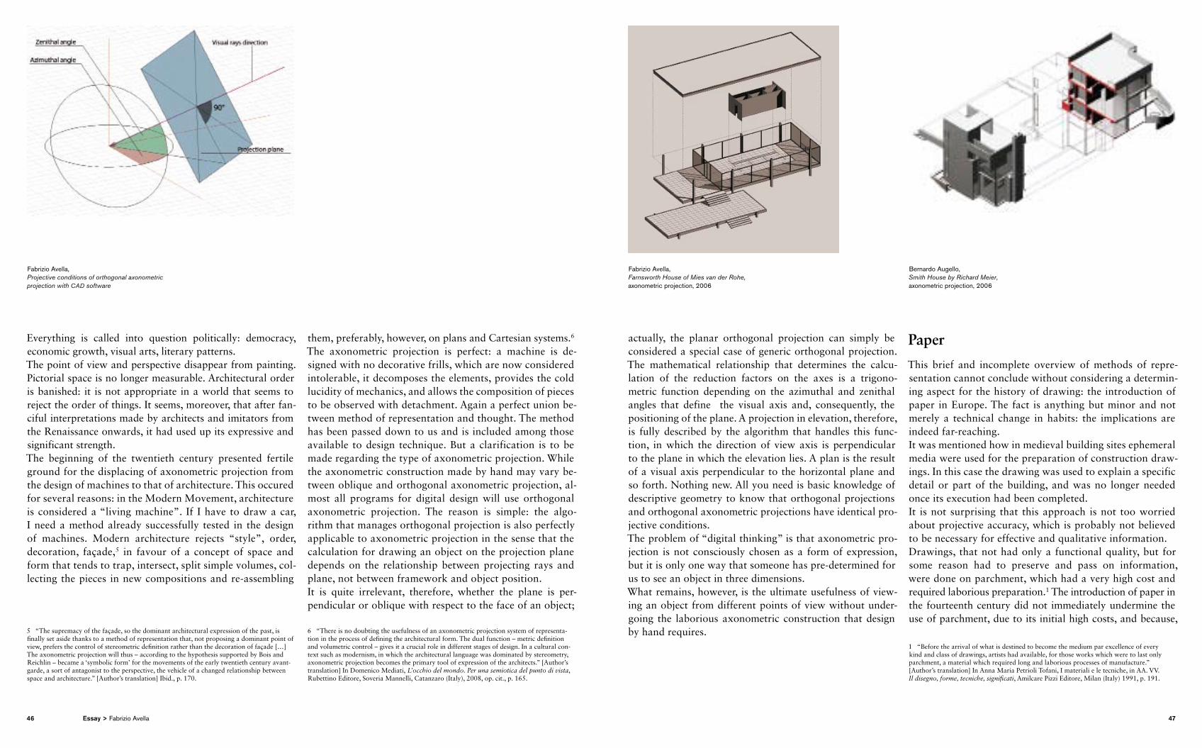
actually, the planar orthogonal projection can simply be considered a special case of generic orthogonal projection. The mathematical relationship that determines the calculation of the reduction factors on the axes is a trigonometric function depending on the azimuthal and zenithal angles that define the visual axis and, consequently, the positioning of the plane. A projection in elevation, therefore, is fully described by the algorithm that handles this function, in which the direction of view axis is perpendicular to the plane in which the elevation lies. A plan is the result of a visual axis perpendicular to the horizontal plane and so forth. Nothing new. All you need is basic knowledge of descriptive geometry to know that orthogonal projections and orthogonal axonometric projections have identical projective conditions.The problem of “digital thinking” is that axonometric projection is not consciously chosen as a form of expression, but it is only one way that someone has predetermined for us to see an object in three dimensions.What remains, however, is the ultimate usefulness of viewing an object from different points of view without undergoing the laborious axonometric construction that design by hand requires.
Paper
This brief and incomplete overview of methods of representation cannot conclude without considering a determining aspect for the history of drawing: the introduction of paper in Europe. The fact is anything but minor and not merely a technical change in habits: the implications are indeed farreaching.It was mentioned how in medieval building sites ephemeral media were used for the preparation of construction drawings. In this case the drawing was used to explain a specific detail or part of the building, and was no longer needed once its execution had been completed. It is not surprising that this approach is not too worried about projective accuracy, which is probably not believed to be necessary for effective and qualitative information.Drawings, that not had only a functional quality, but for some reason had to preserve and pass on information, were done on parchment, which had a very high cost and re quired laborious preparation.1 The introduction of paper in the fourteenth century did not immediately undermine the use of parchment, due to its initial high costs, and because,
1 “Before the arrival of what is destined to become the medium par excellence of every kind and class of drawings, artists had available, for those works which were to last only parchment, a material which required long and laborious processes of manufacture.” [Author’s translation] In Anna Maria Petrioli Tofani, I materiali e le tecniche, in AA. VV. Il disegno, forme, tecniche, significati, Amilcare Pizzi Editore, Milan (Italy) 1991, p. 191.
Fabrizio Avella, Projective conditions of orthogonal axonometric projection with CAD software
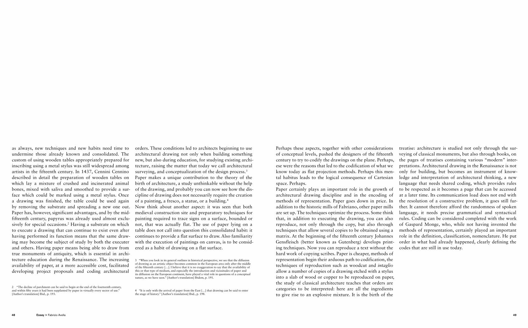
Fabrizio Avella, Farnsworth House of Mies van der Rohe, axonometric projection, 2006
Bernardo Augello, Smith House by Richard Meier, axonometric projection, 2006
46 47Essay > Fabrizio Avella
as always, new techniques and new habits need time to under mine those already known and consolidated. The custom of using wooden tables appropriately prepared for inscribing using a metal stylus was still widespread among artists in the fifteenth century. In 1437, Cennini Cennino described in detail the preparation of wooden tables on which lay a mixture of crushed and incinerated animal bones, mixed with saliva and smoothed to provide a surface which could be marked using a metal stylus. Once a drawing was finished, the table could be used again by removing the substrate and spreading a new one out. Paper has, however, significant advantages, and by the midfifteenth century, papyrus was already used almost exclusively for special occasions.2 Having a substrate on which to execute a drawing that can continue to exist even after having performed its function means that the same drawing may become the subject of study by both the executer and others. Having paper means being able to draw from true monuments of antiquity, which is essential in architecture education during the Renaissance. The increasing availability of paper, at a more accessible cost, facilitated developing project proposals and coding architectural
2 “The decline of parchment can be said to begin at the end of the fourteenth century, and within fifty years it had been supplanted by paper in virtually every sector of use.” [Author’s translation] Ibid., p. 193.
orders. These conditions led to architects beginning to use architectural drawing not only when building something new, but also during education, for studying existing architecture, raising the matter that today we call architectural surveying, and conceptualization of the design process.3
Paper makes a unique contribution to the theory of the birth of architecture, a study unthinkable without the help of the drawing, and probably you can now see how the discipline of drawing does not necessarily require the creation of a painting, a fresco, a statue, or a building.4
Now think about another aspect: it was seen that both medieval construction site and preparatory techniques for painting required to trace signs on a surface, bounded or not, that was actually flat. The use of paper lying on a table does not call into question this consolidated habit: it continues to provide a flat surface to draw. Also famil iarity with the execution of paintings on canvas, is to be considered as a habit of drawing on a flat surface.
3 “When you look in its general outlines in historical perspective, we see that the diffusion of drawing as an artistic object becomes common in the European area only after the middle of the fifteenth century […]. I believe that it is no exaggeration to say that the availability of this or that type of medium, and especially the introduction and vicissitudes of paper and its diffusion on the European continent, have played a vital role in questions of a conceptual nature, as we have seen.” [Author’s translation] Ibidem, p. 191.
4 “It is only with the arrival of paper from the East […] that drawing can be said to enter the stage of history.” [Author’s translation] Ibid., p. 198.
Perhaps these aspects, together with other considerations of conceptual levels, pushed the designers of the fifteenth century to try to codify the drawings on the plane. Perhaps, ese were the reasons that led to the codification of what we know today as flat projection methods. Perhaps this mental habitus leads to the logical consequence of Cartesian space. Perhaps. Paper certainly plays an important role in the growth of archi tectural drawing discipline and in the encoding of methods of representation. Paper goes down in price. In addition to the historic mills of Fabriano, other paper mills are set up. The techniques optimize the process. Some think that, in addition to exe cuting the drawing, you can also reproduce, not only through the copy, but also through techniques that allow several copies to be obtained using a matrix. At the beginning of the fifteenth century Johannes Gensfleisch (better known as Gutenberg) develops printing techniques. Now you can reproduce a text without the hard work of copying scribes. Paper is cheaper, methods of representation begin their arduous path to codification, the techniques of reproduction such as woodcut and intaglio allow a number of copies of a drawing etched with a stylus into a slab of wood or copper to be reproduced on paper, the study of classical architecture teaches that orders are categories to be interpreted: here are all the ingredients to give rise to an explosive mixture. It is the birth of the
treatise: architecture is studied not only through the surveying of classical monuments, but also through books, on the pages of treatises containing various “modern” interpretations. Architectural drawing in the Renaissance is not only for building, but becomes an instrument of knowledge and interpretation of architectural thinking, a new language that needs shared coding, which provides rules to be respected as it becomes a page that can be accessed at a later time. Its communication load does not end with the resolution of a constructive problem, it goes still further. It cannot therefore afford the randomness of spoken language, it needs precise grammatical and syntactical rules. Coding can be considered completed with the work of Gaspard Monge, who, while not having invented the methods of representation, certainly played an important role in the definition, classification, nomenclature. He put order in what had already happened, clearly defining the codes that are still in use today.
48 49Essay > Fabrizio Avella
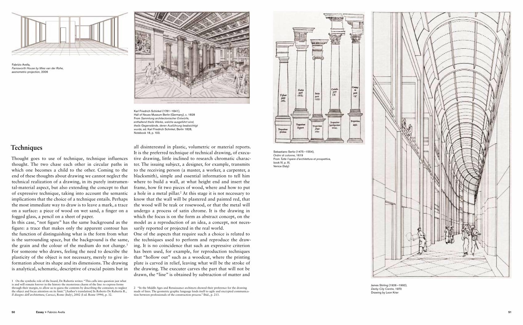
Techniques
Thought goes to use of technique, technique influences thought. The two chase each other in circular paths in which one becomes a child to the other. Coming to the end of these thoughts about drawing we cannot neglect the technical realization of a drawing, in its purely instrumentalmaterial aspect, but also extending the concept to that of expressive technique, taking into account the semantic implications that the choice of a technique entails. Perhaps the most immediate way to draw is to leave a mark, a trace on a surface: a piece of wood on wet sand, a finger on a fogged glass, a pencil on a sheet of paper. In this case, “not figure” has the same background as the figure: a trace that makes only the apparent contour has the function of distinguishing what is the form from what is the surrounding space, but the background is the same, the grain and the colour of the medium do not change.1 For someone who draws, feeling the need to describe the plasticity of the object is not necessary, merely to give information about its shape and its dimensions. The drawing is analytical, schematic, descriptive of crucial points but in
1 On the symbolic role of the board, De Rubertis writes: “This calls into question just what is and will remain forever in the history the mysterious charm of the line: to express forms through their margin, to allow us to guess the contents by describing the container, to neglect the object and focus attention on its limit.” [Author’s translation] In Roberto De Rubertis R., Il disegno dell’architettura, Carocci, Rome (Italy), 2002 (I ed. Rome 1994), p. 32.
all disinterested in plastic, volumetric or material reports. It is the preferred technique of technical drawing, of executive drawing, little inclined to research chromatic character. The issuing subject, a designer, for example, transmits to the receiving person (a master, a worker, a carpenter, a blacksmith), simple and essential information to tell him where to build a wall, at what height end and insert the frame, how fit two pieces of wood, where and how to put a hole in a metal pillar.2 At this stage it is not necessary to know that the wall will be plastered and painted red, that the wood will be teak or rosewood, or that the metal will undergo a process of satin chrome. It is the drawing in which the focus is on the form as abstract concept, on the model as a reproduction of an idea, a concept, not necessarily reported or projected in the real world.One of the aspects that require such a choice is related to the techniques used to perform and reproduce the drawing. It is no coincidence that such an expressive criterion has been used, for example, for reproduction techniques that “hollow out” such as a woodcut, where the printing plate is carved in relief, leaving what will be the stroke of the drawing. The executer carves the part that will not be drawn, the “line” is obtained by subtraction of matter and
2 “In the Middle Ages and Renaissance architects showed their preference for the drawing made of lines. The geometric graphic language lends itself to agile and encrypted communication between professionals of the construction process.” Ibid., p. 213.
Fabrizio Avella, Farnsworth House by Mies van der Rohe, axonometric projection, 2006
Karl Friedrich Schinkel (1781–1841), Hall of Neues Museum Berlin (Germany), c. 1828From Sammlung architectonischer Entwürfe, enthal tend theils Werke, welche ausgeführt sind, theils Gegenstände, deren Ausführung beabsichtigt wurde, ed. Karl Friedrich Schinkel, Berlin 1828, Notebook 18, p. 103.
Sebastiano Serlio (1475 –1554), Ordini di colonne, 1619 From Tutte l’opere d’architettura et prospettiva, book IV, p. III, Venice (Italy)
James Stirling (1926 –1992), Derby City Centre, 1970Drawing by Leon Krier
50 51Essay > Fabrizio Avella
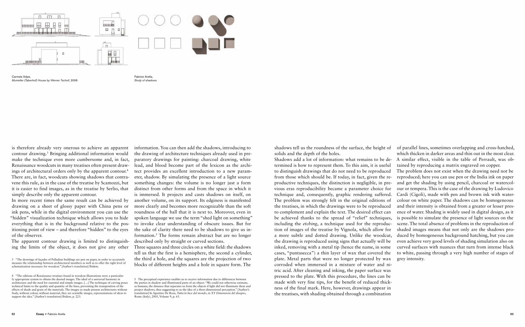
is therefore already very onerous to achieve an apparent contour drawing.3 Bringing additional information would make the technique even more cumbersome and, in fact, Renaissance woodcuts in many treatises often present drawings of architectural orders only by the apparent contour.4 There are, in fact, woodcuts showing shadows that contravene this rule, as in the case of the treatise by Scamozzi, but it is easier to find images, as in the treatise by Serlio, that simply describe only the apparent contour.In more recent times the same result can be achieved by drawing on a sheet of glossy paper with China pens or ink pens, while in the digital environment you can use the
“hidden” visualization technique which allows you to hide every thing that is in the background relative to the positioning point of view – and therefore “hidden” to the eyes of the observer.The apparent contour drawing is limited to distinguishing the limits of the object, it does not give any other
3 “The drawings of façades of Palladian buildings are pen on paper, in order to accurately measure the relationship between architectural members as well as to offer the right level of schematization necessary for woodcut.” [Author’s translation] Ibidem.
4 “The editions of Renaissance treatises found in woodcut illustrations were a particularly appropriate system to obtain the desired images. The ideal of a universal harmony in architecture and the need for essential and simple images. […] The technique of carving poses technical limits to the quality and quantity of the lines, preventing the transposition of the effects of shade and grain of the materials. The images so made present architectures without body, without colour, without material, they are scientific images, representations of ideas to support the idea.” [Author’s translation] Ibidem, p. 223.
information. You can then add the shadows, introducing to the drawing of architecture techniques already used in preparatory drawings for painting: charcoal drawing, white lead, and blood become part of the lexicon as the architect provides an excellent introduction to a new parameter, shadow. By simulating the presence of a light source something changes: the volume is no longer just a form distinct from other forms and from the space in which it is immersed. It projects and casts shadows on itself, on another volume, on its support. Its edginess is manifested more clearly and becomes more recognizable than the soft roundness of the ball that it is next to. Moreover, even in spoken language we use the term “shed light on something” to invoke clear understanding of obscure issues. But for the sake of clarity there need to be shadows to give us information.5 The forms remain abstract but are no longer described only by straight or curved sections. Three squares and three circles on a white field: the shadows tell us that the first is a hemisphere, the second a cylinder, the third a hole, and the squares are the projection of two blocks of different heights and a hole in square form. The
5 The perceptual experience enables us to receive information due to differences between the parties in shadow and illuminated parts of an object: “We could not otherwise estimate, as humans, the distance that separates us from the objects if light did not illuminate them and project shadows, thus suggesting to us the idea of a threedimensional perception.” [Author’s translation] In Agostino De Rosa, Tutta la luce del mondo, in XY Dimensioni del disegno, Rome (Italy), 2005, Volume 9, p. 63.
shadows tell us the roundness of the surface, the height of solids and the depth of the holes.Shadows add a lot of information: what remains to be determined is how to represent them. To this aim, it is useful to distinguish drawings that do not need to be reproduced from those which should be. If today, in fact, given the reproductive techniques, the distinction is negligible, in previous eras reproducibility became a parameter choice for technique and, consequently, graphic rendering suffered. The problem was strongly felt in the original editions of the treatises, in which the drawings were to be reproduced to complement and explain the text. The desired effect can be achieved thanks to the spread of “relief” techniques, including the etching, a technique used for the reproduction of images of the treatise by Vignola, which allow for a more subtle and dotted drawing. Unlike the woodcut, the drawing is reproduced using signs that actually will be inked, removing with a metal tip (hence the name, in some cases, “puntasecca”) a thin layer of wax that covered the plate. Metal parts that were no longer protected by wax cor roded when immersed in a mixture of water and nitric acid. After cleaning and inking, the paper surface was pressed to the plate. With this procedure, the lines can be made with very fine tips, for the benefit of reduced thickness of the final mark. Here, however, drawings appear in the treatises, with shading obtained through a combination
of parallel lines, sometimes overlapping and crosshatched, which thicken in darker areas and thin out in the most clear. A similar effect, visible in the table of Perrault, was obtained by reproducing a matrix engraved on copper.The problem does not exist when the drawing need not be reproduced; here you can use pen or the India ink on paper and get the shading by using pencil, charcoal or watercolour or tempera. This is the case of the drawing by Ludovico Cardi (Cigoli), made with pen and brown ink with watercolour on white paper. The shadows can be homogeneous and their intensity is obtained from a greater or lesser presence of water. Shading is widely used in digital design, as it is possible to simulate the presence of light sources on the scene. The total absence of problems in the reproduction of shaded images means that not only are the shadows produced by homog eneous background hatching, but you can even achieve very good levels of shading simulation also on curved surfaces with nuances that turn from intense black to white, passing through a very high number of stages of grey intensity.
Carmela Volpe, Mumelter (Taberhof) House by Werner Tscholl, 2006
Fabrizio Avella, Study of shadows
52 53Essay > Fabrizio Avella
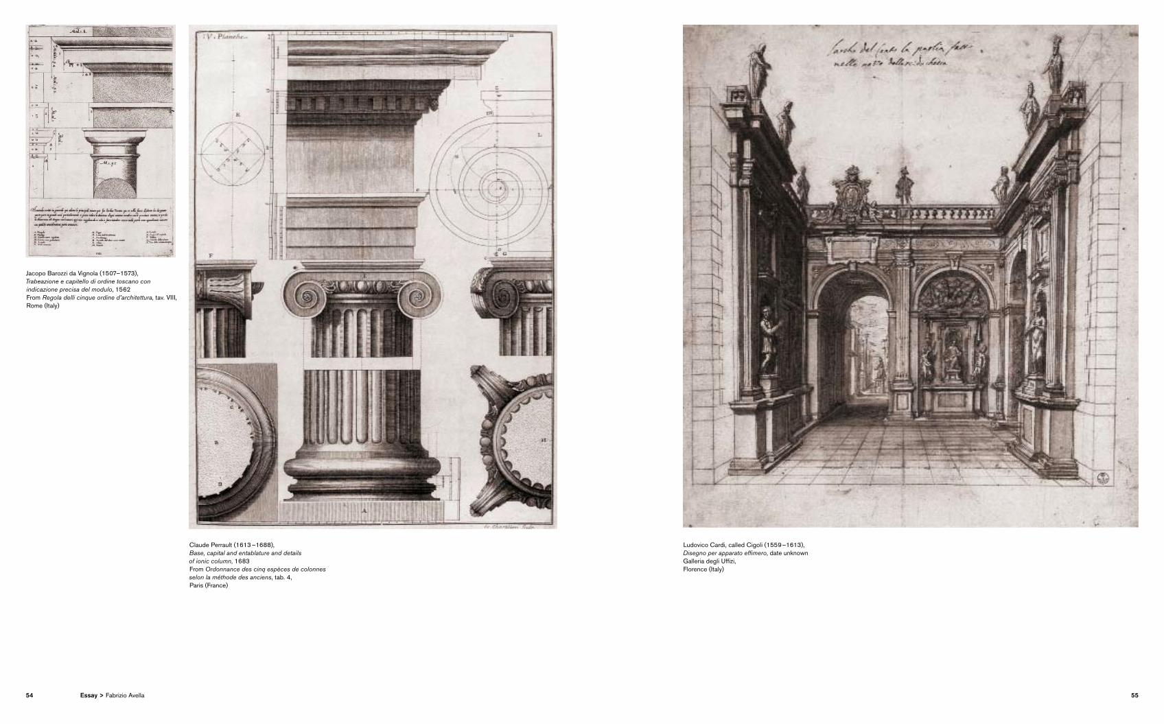
Jacopo Barozzi da Vignola (1507–1573), Trabeazione e capitello di ordine toscano con indicazione precisa del modulo, 1562 From Regola delli cinque ordine d’architettura, tav. VIII,Rome (Italy)
Claude Perrault (1613 –1688), Base, capital and entablature and details of ionic column, 1683 From Ordonnance des cinq espèces de colonnes selon la méthode des anciens, tab. 4,Paris (France)
Ludovico Cardi, called Cigoli (1559 –1613), Disegno per apparato effimero, date unknown Galleria degli Uffizi, Florence (Italy)
54 55Essay > Fabrizio Avella
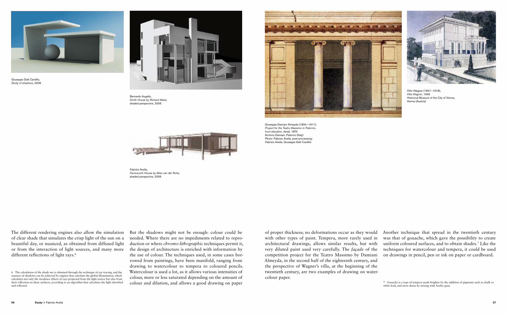
The different rendering engines also allow the simulation of clear shade that simulates the crisp light of the sun on a beautiful day, or nuanced, as obtained from diffused light or from the interaction of light sources, and many more different reflections of light rays.6
6 The calculation of the shade net is obtained through the technique of ray tracing, and the nuances of shadows can be achieved by engines that calculate the global illumination, which calculates not only the incidence effects of rays projected from the light source but also from their reflection on these surfaces, according to an algorithm that calculates the light absorbed and reflected.
But the shadows might not be enough: colour could be needed. Where there are no impediments related to reproduction or where chromo-lithographic techniques permit it, the design of architecture is enriched with information by the use of colour. The techniques used, in some cases borrowed from paintings, have been manifold, ranging from drawing to watercolour to tempera to coloured pencils. Watercolour is used a lot, as it allows various intensities of colour, more or less saturated depending on the amount of colour and dilution, and allows a good drawing on paper
of proper thickness; no deformations occur as they would with other types of paint. Tempera, more rarely used in architectural drawings, allows similar results, but with very diluted paint used very carefully. The façade of the competition project for the Teatro Massimo by Damiani Almeyda, in the second half of the eighteenth century, and the perspective of Wagner’s villa, at the beginning of the twentieth century, are two examples of drawing on watercolour paper.
Another technique that spread in the twentieth century was that of gouache, which gave the possibility to create uniform coloured surfaces, and to obtain shades.7 Like the techniques for watercolour and tempera, it could be used on drawings in pencil, pen or ink on paper or cardboard.
7 Gouache is a type of tempera made brighter by the addition of pigments such as chalk or white lead, and more dense by mixing with Arabic gum.
Giuseppe Dalli Cardillo, Study of shadows, 2008
Bernardo Augello, Smith House by Richard Meier, shaded perspective, 2006
Giuseppe Damiani Almeyda (1834 –1911), Project for the Teatro Massimo in Palermo, front elevation, detail, 1874 Archivio Damiani, Palermo (Italy) Photo: Fabrizio Avella, post-processing: Fabrizio Avella, Giuseppe Dalli Cardillo
Fabrizio Avella, Farnsworth House by Mies van der Rohe, shaded perspective, 2006
Otto Wagner (1841–1918), Villa Wagner, 1905 Historical Museum of the City of Vienna, Vienna (Austria)
56 57Essay > Fabrizio Avella
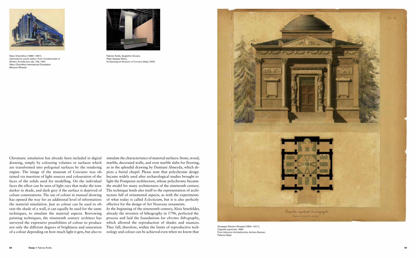
Chromatic simulation has already been included in digital drawing, simply by colouring volumes or surfaces which are transformed into polygonal surfaces by the rendering engine. The image of the museum of Corciano was obtained via insertion of light sources and colouration of the faces of the solids used for modelling. On the individual faces the effect can be seen of light rays that make the tone darker in shade, and dark grey if the surface is deprived of colour connotations. The use of colour in manual drawing has opened the way for an additional level of information: the material simulation. Just as colour can be used to obtain the shade of a wall, it can equally be used for the same techniques, to simulate the material aspects. Borrowing painting techniques, the nineteenth century architect has surveyed the expressive possibilities of colour to produce not only the different degrees of brightness and saturation of a colour depending on how much light it gets, but also to
simulate the characteristics of material surfaces. Stone, wood, marble, decorated walls, and even marble slabs for flooring, as in the splendid drawing by Damiani Almeyda, which depicts a burial chapel. Please note that polychrome design became widely used after archaeological studies brought to light the Pompeian architecture, whose polychromy became the model for many architectures of the nineteenth century. The technique lends also itself to the representation of architecture full of ornamental aspects, as with the experiments of what today is called Eclecticism, but it is also perfectly effect ive for the design of Art Nouveau ornaments. At the beginning of the nineteenth century, Alois Senefelder, already the inventor of lithography in 1796, perfected the process and laid the foundations for chromo lithography, which allowed the reproduction of shades and nuances. They fall, therefore, within the limits of reproductive technology and colour can be achieved even when we know that
Yakov Chernikhov (1889 –1951), Hydroelectric power station, From Fundamentals of Modern Architecture, tab. 149, 1931 Yakov Chernikhov International Foundation Moscow (Russia)
Fabrizio Avella, Guglielmo Acciaro, Pepe Vasquez Reina, Archaeological Museum of Corciano (Italy), 2002
Giuseppe Damiani Almeyda (1834 –1911), Cappella sepolcrale, 1890 From Istituzioni Architettoniche, Archivio Damiani, Palermo (Italy)
58 59Essay > Fabrizio Avella
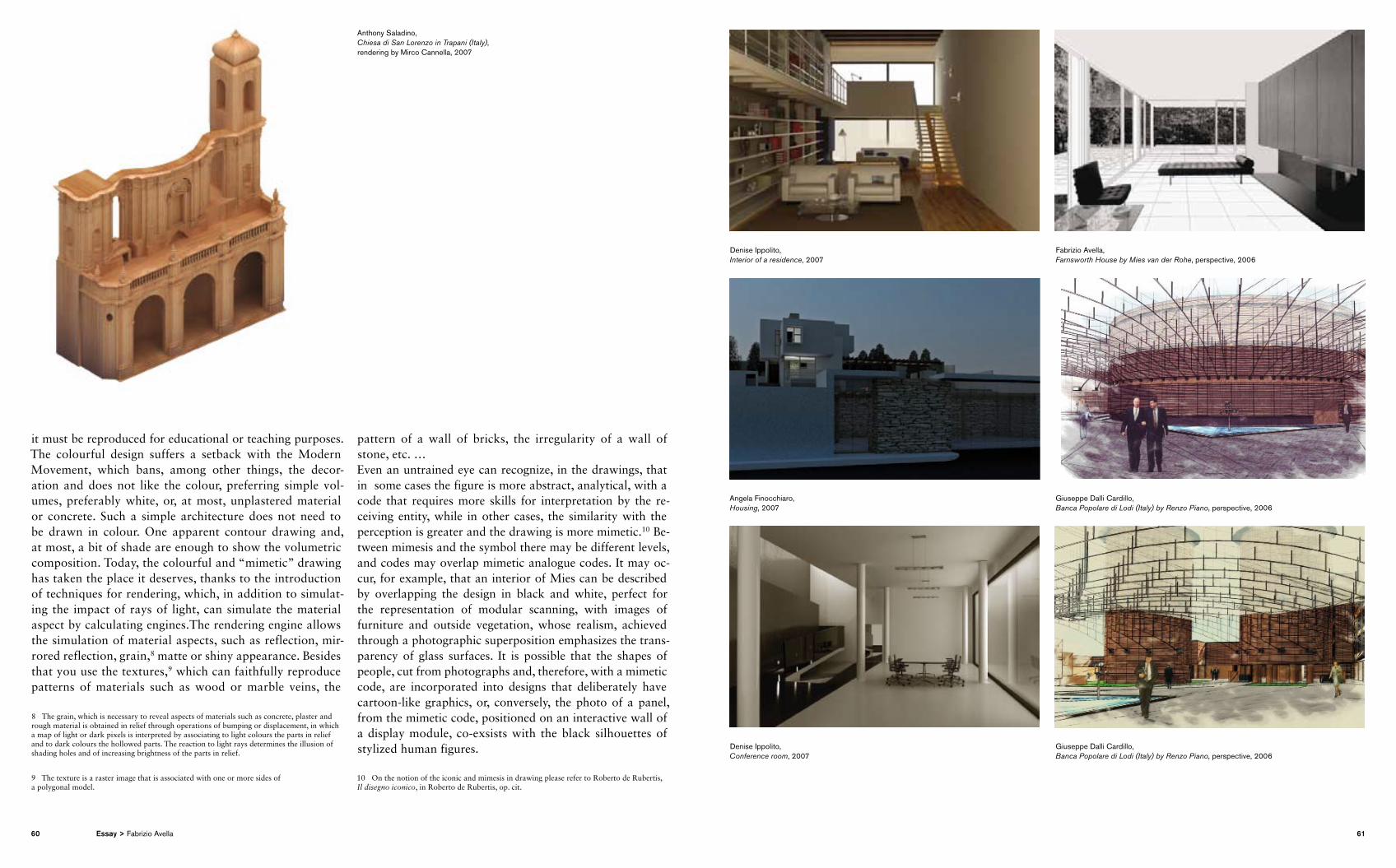
it must be reproduced for educational or teaching purposes. The colourful design suffers a setback with the Modern Movement, which bans, among other things, the decoration and does not like the colour, preferring simple volumes, preferably white, or, at most, unplastered material or concrete. Such a simple architecture does not need to be drawn in colour. One apparent contour drawing and, at most, a bit of shade are enough to show the volumetric composition. Today, the colourful and “mimetic” drawing has taken the place it deserves, thanks to the introduction of techniques for rendering, which, in addition to simulating the impact of rays of light, can simulate the material aspect by calculating engines.The rendering engine allows the simulation of material aspects, such as reflection, mirrored reflection, grain,8 matte or shiny appearance. Besides that you use the textures,9 which can faithfully reproduce patterns of materials such as wood or marble veins, the
8 The grain, which is necessary to reveal aspects of materials such as concrete, plaster and rough material is obtained in relief through operations of bumping or displacement, in which a map of light or dark pixels is interpreted by associating to light colours the parts in relief and to dark colours the hollowed parts. The reaction to light rays determines the illusion of shading holes and of increasing brightness of the parts in relief.
9 The texture is a raster image that is associated with one or more sides of a polygonal model.
pattern of a wall of bricks, the irregularity of a wall of stone, etc. …Even an untrained eye can recognize, in the drawings, that in some cases the figure is more abstract, analytical, with a code that requires more skills for interpretation by the receiving entity, while in other cases, the similarity with the perception is greater and the drawing is more mimetic.10 Between mimesis and the symbol there may be different levels, and codes may overlap mimetic analogue codes. It may occur, for example, that an interior of Mies can be described by overlapping the design in black and white, perfect for the representation of modular scanning, with images of furniture and outside vegetation, whose realism, achieved through a photographic superposition emphasizes the transparency of glass surfaces. It is possible that the shapes of people, cut from photographs and, therefore, with a mimetic code, are incorporated into designs that deliberately have cartoonlike graphics, or, conversely, the photo of a panel, from the mimetic code, positioned on an interactive wall of a display module, coexsists with the black silhouettes of stylized human figures.
10 On the notion of the iconic and mimesis in drawing please refer to Roberto de Rubertis, Il disegno iconico, in Roberto de Rubertis, op. cit.
Denise Ippolito, Interior of a residence, 2007
Angela Finocchiaro, Housing, 2007
Fabrizio Avella, Farnsworth House by Mies van der Rohe, perspective, 2006
Giuseppe Dalli Cardillo, Banca Popolare di Lodi (Italy) by Renzo Piano, perspective, 2006
Giuseppe Dalli Cardillo, Banca Popolare di Lodi (Italy) by Renzo Piano, perspective, 2006
Denise Ippolito, Conference room, 2007
Anthony Saladino, Chiesa di San Lorenzo in Trapani (Italy), rendering by Mirco Cannella, 2007
60 61Essay > Fabrizio Avella
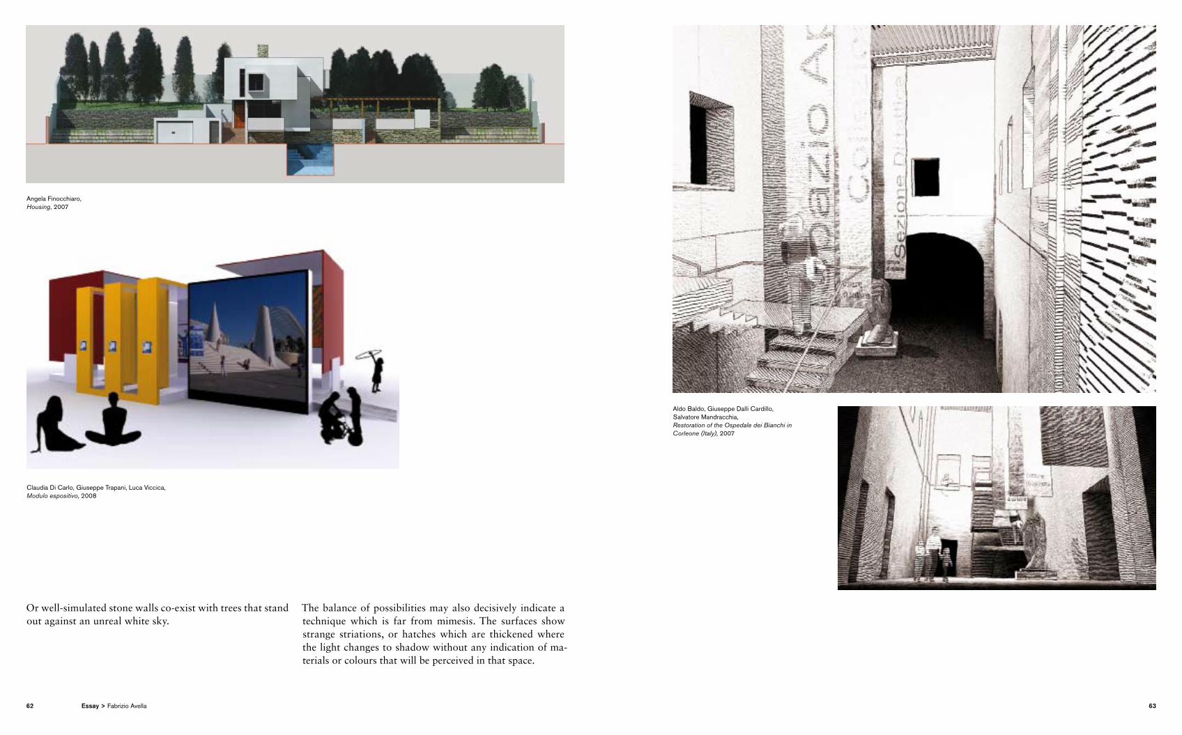
Or wellsimulated stone walls coexist with trees that stand out against an unreal white sky.
The balance of possibilities may also decisively indicate a technique which is far from mimesis. The surfaces show strange striations, or hatches which are thickened where the light changes to shadow without any indication of materials or colours that will be perceived in that space.
Angela Finocchiaro, Housing, 2007
Claudia Di Carlo, Giuseppe Trapani, Luca Viccica, Modulo espositivo, 2008
Aldo Baldo, Giuseppe Dalli Cardillo, Salvatore Mandracchia, Restoration of the Ospedale dei Bianchi in Corleone (Italy), 2007
62 63Essay > Fabrizio Avella
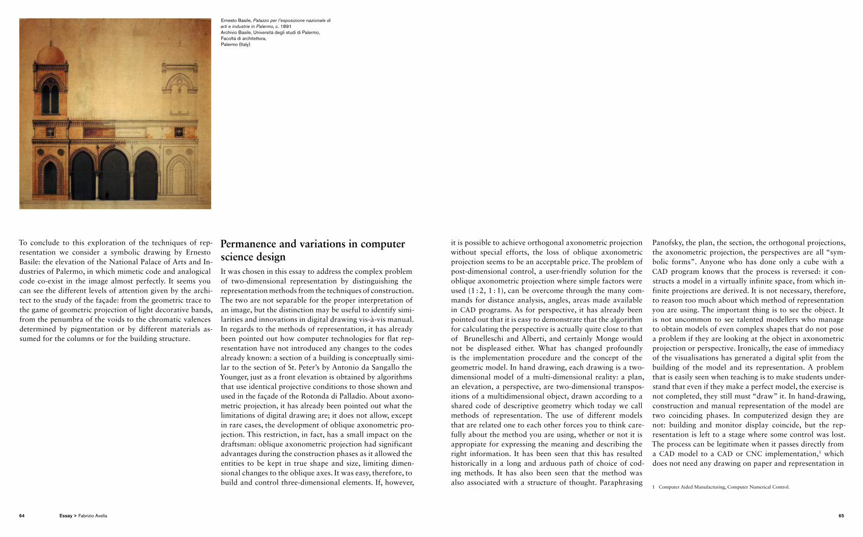
To conclude to this exploration of the techniques of representation we consider a symbolic drawing by Ernesto Basile: the elevation of the National Palace of Arts and Industries of Palermo, in which mimetic code and analogical code coexist in the image almost perfectly. It seems you can see the different levels of attention given by the architect to the study of the façade: from the geometric trace to the game of geometric projection of light decorative bands, from the penumbra of the voids to the chromatic valences determined by pigmentation or by different materials assumed for the columns or for the building structure.
Permanence and variations in computer science design It was chosen in this essay to address the complex problem of twodimensional representation by distinguishing the representation methods from the techniques of con struction. The two are not separable for the proper interpret ation of an image, but the distinction may be useful to identify similarities and innovations in digital drawing visàvis manual. In regards to the methods of representation, it has already been pointed out how computer technologies for flat representation have not introduced any changes to the codes already known: a section of a building is concep tually similar to the section of St. Peter’s by Antonio da Sangallo the Younger, just as a front elevation is obtained by algorithms that use identical projective conditions to those shown and used in the façade of the Rotonda di Palladio. About axonometric projection, it has already been pointed out what the limitations of digital drawing are; it does not allow, except in rare cases, the development of oblique axonometric projection. This restriction, in fact, has a small impact on the draftsman: oblique axonometric projection had significant advantages during the construction phases as it allowed the entities to be kept in true shape and size, limiting dimensional changes to the oblique axes. It was easy, therefore, to build and control threedimensional elements. If, however,
it is possible to achieve orthogonal axonometric projection without special efforts, the loss of oblique axonometric projection seems to be an acceptable price. The problem of postdimensional control, a userfriendly solution for the oblique axonometric projection where simple factors were used (1 : 2, 1 : 1), can be overcome through the many commands for distance analysis, angles, areas made available in CAD programs. As for perspective, it has already been pointed out that it is easy to demonstrate that the algorithm for calculating the perspective is actually quite close to that of Brunelleschi and Alberti, and certainly Monge would not be displeased either. What has changed profoundly is the implementation procedure and the concept of the geometric model. In hand drawing, each drawing is a twodimensional model of a multidimensional reality: a plan, an elevation, a perspective, are twodimensional transpositions of a multidimensional object, drawn according to a shared code of descriptive geometry which today we call methods of representation. The use of different models that are related one to each other forces you to think carefully about the method you are using, whether or not it is appropiate for expressing the meaning and describing the right information. It has been seen that this has resulted historically in a long and arduous path of choice of coding methods. It has also been seen that the method was also associated with a structure of thought. Paraphrasing
Panofsky, the plan, the section, the orthogonal projections, the axonometric projection, the perspectives are all “symbolic forms”. Anyone who has done only a cube with a CAD program knows that the process is reversed: it constructs a model in a virtually infinite space, from which infinite projections are derived. It is not necessary, therefore, to reason too much about which method of representation you are using. The important thing is to see the object. It is not uncommon to see talented modellers who manage to obtain models of even complex shapes that do not pose a problem if they are looking at the object in axonometric projection or perspective. Ironically, the ease of immediacy of the visualisations has generated a digital split from the building of the model and its representation. A problem that is easily seen when teaching is to make students understand that even if they make a perfect model, the exercise is not completed, they still must “draw” it. In handdrawing, construction and manual representation of the model are two coinciding phases. In computerized design they are not: building and monitor display coincide, but the representation is left to a stage where some control was lost. The process can be legitimate when it passes directly from a CAD model to a CAD or CNC implementation,1 which does not need any drawing on paper and representation in
1 Computer Aided Manufacturing, Computer Numerical Control.
Ernesto Basile, Palazzo per l’esposizione nazionale di arti e industrie in Palermo, c. 1891 Archivio Basile, Universitá degli studi di Palermo, Facoltá di architettura, Palermo (Italy)
64 65Essay > Fabrizio Avella
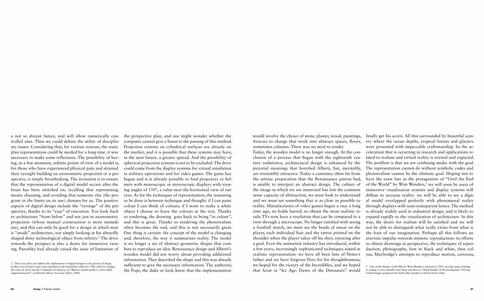
a not so distant future, and will allow numerically controlled sites. Then we could debate the utility of disciplinary issues. Considering that, for various reasons, the static plan representation could be needed for a long time, it was ne cessary to make some reflections. The possibility of having, in a few moments, infinite points of view of a model is, for those who have experienced physical pain and strained their eyesight building an axonometric projection or a perspective, is simply breathtaking. The invitation is to ensure that the representation of a digital model occurs after the brain has been switched on, recalling that representing means choosing, and avoiding that someone else (the program or the limits on its use) chooses for us. The positive aspects of digital design include the “revenge” of the perspective, thanks to its “ease” of execution. You look back to architecture “from below” and not just in axonometric projection (whose manual construction is more immediate), and this can only be good for a design in which man is “inside” architecture, not simply looking at his absurdly shaped shiny technological object from infinity.2 The drive towards the prospect is also a desire for immersive viewing. Panofsky had already raised the issue of limitation of
2 This essay does not address the implications of digital design on the genesis of shape, as this is too broad a topic and unrelated to the immediate objective. That calls for reading the essay by Livio Sacchi, Il digitale: un bilancio, in “Ikhnos, Analisi grafica e storia della rappresentazione”, Lombardi editore, Syracuse (Italy), 2008.
the perspective plan, and one might wonder whether the computer cannot give a boost to the passing of this method. Projection systems on cylindrical surfaces are already on the market, and it is possible that these systems may have, in the near future, a greater spread. And the possibility of spherical projection systems is not to be excluded. The drive could come from the display systems for virtual simulation in military operations and for video games. The game has begun and it is already possible to find projectors or helmets with monoscopic or stereoscopic displays with viewing angles of 150°, a value near the horizontal view of our eyes. As for the techniques of representation, the reasoning to be done is between technique and thought: if I can paint colour I can think of colours, if I want to make a white object I choose to leave the colours in the tray. Thanks to rendering, the drawing goes back to being “in colour”, and this is great. Thanks to rendering the photorealism often becomes the end, and this is not necessarily great. One thing is certain: the concept of the model is changing and, therefore, the way it summarizes reality. The model is no longer a set of abstract geometric shapes that combine to reproduce an idea: Renaissance design and Alberti’s wooden model did not worry about providing additional information. They described the shape and this was already sufficient to give the necessary information. The authority, the Pope, the duke or lord, knew that the implementation
would involve the choice of stone, plaster, wood, paintings, frescoes to change that work into abstract spaces, floors, sometimes columns. There was no need to render.Today, the wooden model is no longer enough. At the conclusion of a process that began with the eighteenth century vedutistica, architectural design is enhanced by the pictor ial meanings that horrified Alberti, but, inevitably, are irresistibly attractive. Today a customer, often far from the artistic preparation that the Renaissance patron had, is unable to interpret an abstract design. The culture of the image in which we are immersed has lost the common sense capacity of abstraction, we must look to understand and we must see something that is as close as possible to reality. Manufacturers of video games began a race a long time ago, no holds barred, to obtain the most realistic result; TVs now have a resolution that can be compared to a view through a microscope. No longer satisfied with seeing a football match, we must see the beads of sweat on the player, each individual hair and the tattoo printed on the shoulder when the player takes off his shirt, rejoicing after a goal. Even the animation industry has introduced, within a few years, increasingly sophisticated techniques aimed at realistic representation: we have all been fans of Nemo’s father and we have forgiven Dori for his thoughtlessness; we hoped for the victory of the Incredibles, and we hoped that Scrat in “Ice Age: Dawn of the Dinosaurs” would
finally get his acorn. All this surrounded by beautiful scenery where the ocean depths, tropical forests and glaciers were presented with impeccable craftsmanship. So the acceleration that is occurring in research and applications related to realism and virtual reality is normal and expected. The problem is that we are confusing media with the goal. The representation cannot do without symbolic codes and photorealism cannot be the ultimate goal. Hoping not to have the same fate as the protagonists of “Until the End of the World” by Wim Wenders,3 we will soon be users of immersive visualization systems and display systems will diffuse to increase reality: we will be able to see a digital model overlapped perfectly with phenomenal reality through displays with semitransparent lenses. The method is already widely used in industrial design, and is likely to expand rapidly to the visualization of architecture. In this way, the desire for realism will be satisfied and we will not be able to distinguish what really exists from what is the fruit of our imagination. Perhaps all this follows an atavistic impulse towards mimetic reproduction: its efforts to obtain drawings in perspective, the techniques of reproduction, photography, first in black and white, then colour, Muybridge’s attempts to reproduce motion, cartoons,
3 One of the themes of the film by Wim Wenders, released in 1991, was the issues relating to testing a visor, initially aims show pictures to a blind mother of the protagonist. Viewing virtual images progressively leads other people to detach from reality.
66 67Essay > Fabrizio Avella
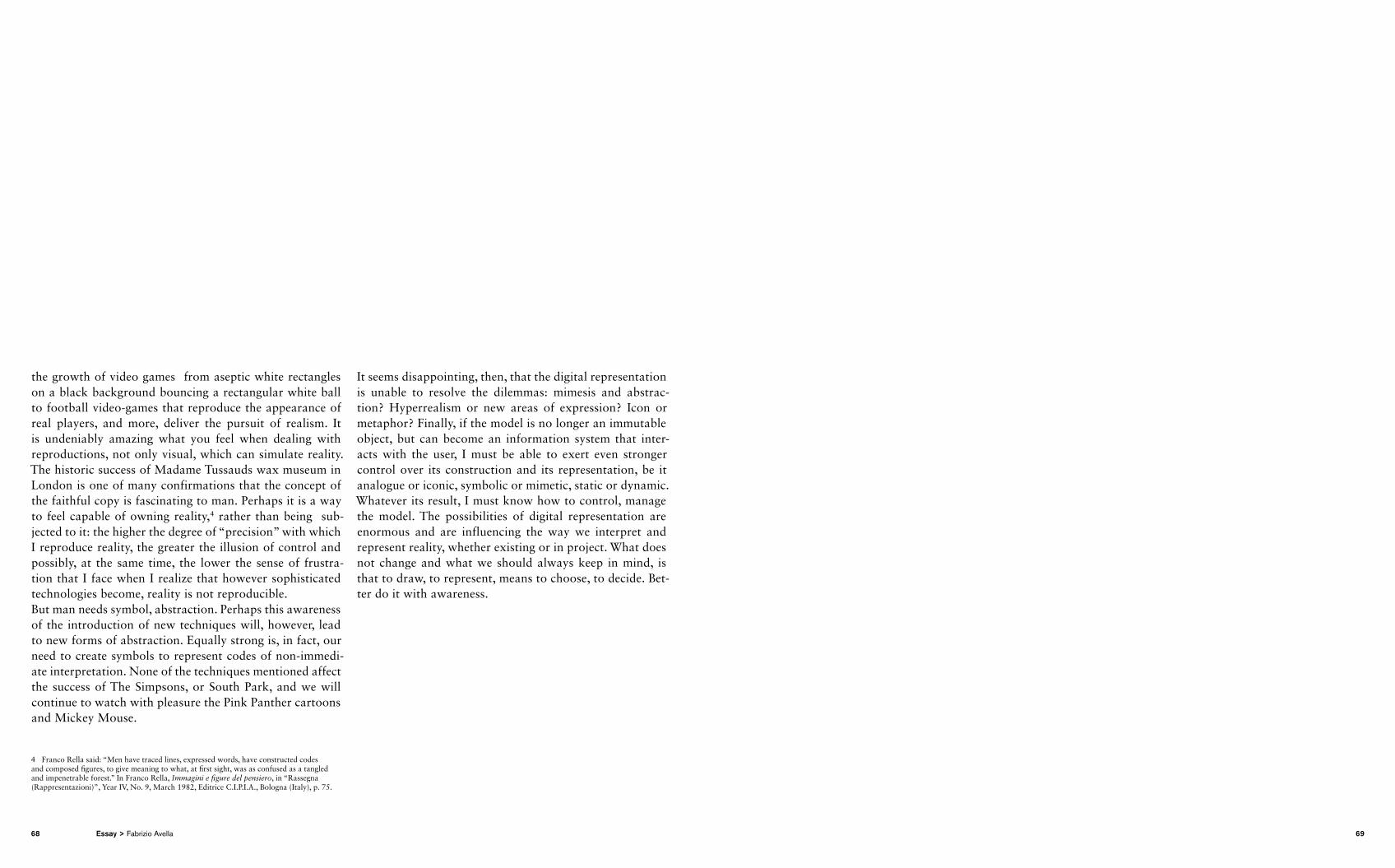
the growth of video games from aseptic white rectangles on a black background bouncing a rectangular white ball to football videogames that reproduce the appearance of real players, and more, deliver the pursuit of realism. It is undeniably amazing what you feel when dealing with reproductions, not only visual, which can simulate reality. The historic success of Madame Tussauds wax museum in London is one of many confirmations that the concept of the faithful copy is fascinating to man. Perhaps it is a way to feel capable of owning reality,4 rather than being subjected to it: the higher the degree of “precision” with which I reproduce reality, the greater the illusion of control and possibly, at the same time, the lower the sense of frustration that I face when I realize that however sophisticated technologies become, reality is not reproducible. But man needs symbol, abstraction. Perhaps this awareness of the introduction of new techniques will, however, lead to new forms of abstraction. Equally strong is, in fact, our need to create symbols to represent codes of nonimmediate interpretation. None of the techniques mentioned affect the success of The Simpsons, or South Park, and we will continue to watch with pleasure the Pink Panther cartoons and Mickey Mouse.
4 Franco Rella said: “Men have traced lines, expressed words, have constructed codes and composed figures, to give meaning to what, at first sight, was as confused as a tangled and impenetrable forest.” In Franco Rella, Immagini e figure del pensiero, in “Rassegna (Rappresentazioni)”, Year IV, No. 9, March 1982, Editrice C.I.P.I.A., Bologna (Italy), p. 75.
It seems disappointing, then, that the digital representation is unable to resolve the dilemmas: mimesis and abstraction? Hyperrealism or new areas of expression? Icon or metaphor? Finally, if the model is no longer an immutable object, but can become an information system that interacts with the user, I must be able to exert even stronger control over its construction and its representation, be it analogue or iconic, symbolic or mimetic, static or dynamic. Whatever its result, I must know how to control, manage the model. The possibilities of digital representation are enormous and are influencing the way we interpret and represent reality, whether existing or in project. What does not change and what we should always keep in mind, is that to draw, to represent, means to choose, to decide. Better do it with awareness.
68 69Essay > Fabrizio Avella
The Deutsche Bibliothek lists this publication in the Deutsche Nationalbibliografie; detailed bibliographic data is available on the internet at http://dnb.ddb.de
ISBN 9783938666630© 2009 by DOM publishers, Berlinwww.dompublishers.com
This work is subject to copyright. All rights are reserved, whether the whole or part of the material is concerned, specifically the rights of translation, reprinting, recitation, broadcasting, reproduction on microfilms or in other ways, and storage or processing in data bases. Sources and owners of rights are stated to the best of our knowledge; please signal any we have might omitted.
Editor: Fabio SchillaciEditorial Staff: Uta KeilEnglish Translation: Melanie Flynn, Angela EggersProofreading: Meredith DaleDesign: Daniela Donadei
I wish to thank all those who in different ways contributed towards the realisation of this book:
Natascha and Philipp Meuser, Mandy Kasek,Uta Keil, Ralph Petermann, Juliane Kukla, Wera Pahl, Jennifer Tobolla, Daniel Festag, Inna Bagrikova, Lena Boyko, Nicole Wolf, Daniela Donadei, Cornelia Dörries, Heiko Mattausch, Paul Angelier, Alessandra Raponi, Niels Fischer, Andrej Schmidt and Anna Jan, Omar Jaramillo Traverso, Salvator John Liotta, Alessandra Traina, Roberto Pelliccia, Carmelo Zappulla, Massimo Tepedino, Christoph Stinn, Julia Kaulbach.
Fabio Schillaci (Italy, b. 1977) is a licensed architect in Italy. He founded Architectural Noise (2000) and FAN (2006). He received an honourable mention at Europan 8 (2006) and a Design Merit Award at Feidad 2005. His works have been shown and published worldwide, for example in Tokyo, Warsaw, Quito, Taipei, Milan and Athens. Fabio Schillaci lives and works in Berlin.
Fabrizio Avella (Italy, b. 1968) graduated in architecture in 1994. In 2000 he obtained a PhD in Surveying and Representation of Architecture and the Environment at the Department of Representation of the University of Palermo. He is researcher and currently teaching at the Faculty of Architecture of the University of Palermo and at the Faculty of Architecture of the University of Agrigento. He practises as a designer, working with several architects in charge of interior renovation, restoration of civil and religious buildings, museum exhibitions, residential buildings, commercial buildings, and landscape design. Fabrizio Avella lives and works in Palermo.
Augusto Romano Burelli (Italy, b. 1938) is Professor of Architectural Composition. From 1970 to 2006 he taught at the Istituto Universitario di Architettura in Venice (Italy). He is currently the dean of the degree course in Architecture at the University of Udine (Italy). He researches on architectural design and urban planning with a specific interest in the architectural culture of the city, traditions of settlement, and their morphological and typological structures. He has been participating since 1991 in the critical reconstruction of Berlin and Potsdam (Germany). He has published books and articles on the relationship between architecture and its origins, and the relationship between architecture, its teaching and its typological codes. Among his architectural works in Friuli (Italy), Potsdam and Berlin (Germany) are residential houses, town halls, churches and university buildings. Augusto Romano Burelli lives and works in Udine, Berlin and Venice.