Embed Size (px)
Citation preview
Construction and control of a physiological articulatory modelJianwu Danga)
School of Information Science, Japan Advanced Institute of Science and Technology, Ishikawa, Japan,and ATR Human Information Science Laboratories, Kyoto, Japan
Kiyoshi HondaATR Human Information Science Laboratories, Kyoto, Japan
~Received 16 May 2003; revised 17 October 2003; accepted 6 November 2003!
A physiological articulatory model has been constructed using a fast computation method, whichreplicates midsagittal regions of the speech organs to simulate articulatory movements duringspeech. This study aims to improve the accuracy of modeling by using the displacement-basedfinite-element method and to develop a new approach for controlling the model. A‘‘semicontinuum’’ tongue tissue model was realized by a discrete truss structure with continuumviscoelastic cylinders. Contractile effects of the muscles were systemically examined based onmodel simulations. The results indicated that each muscle drives the tongue toward an equilibriumposition ~EP! corresponding to the magnitude of the activation forces. The EPs shiftedmonotonically as the activation force increased. The monotonic shift revealed a unique and invariantmapping, referred to as anEP map, between a spatial position of the articulators and the muscleforces. This study proposes a control method for the articulatory model based on the EP maps, inwhich co-contractions of agonist and antagonist muscles are taken into account. By utilizing theco-contraction, the tongue tip and tongue dorsum can be controlled to reach their targetsindependently. Model simulation showed that the co-contraction of agonist and antagonist musclescould increase the stability of a system in dynamic control. ©2004 Acoustical Society of America.@DOI: 10.1121/1.1639325#
PACS numbers: 43.70.Bk, 43.70.Aj, 43.70.Jt@AL # Pages: 853–870
ion
toehg
ap
r-eduu
bphet
hean
ry
de
eterentto
amalessium
alenalgeo-
l
d
jaw,n-of
le toruc-uta-ft
elintse-nt.
I. INTRODUCTION
The production of speech involves the fine coordinatof a serially ordered stream of changing articulatory, larygeal, and respiratory movements. These skilled articulamovements are concerned with well-practiced and ovlearned muscular behaviors. A number of speech researchave endeavored to discover the relationship between tonmovement and muscle activation via experimentalproaches such as EMG experiments~Baeret al., 1988; Dangand Honda, 1997!. For the muscles involved in speech ogans, however, experimental observations have succefor only a few large muscles, such as the extrinsic tongmuscles. The functions of the intrinsic muscles of the tonghave been investigated using tagged MRI~Niimi et al.,1994!, or tagged cine-MRI~Stoneet al., 2001!, but the ac-curacy of such investigations is questionable, since a numof muscles are generally coactivated even to form a simmovement. Furthermore, it is often difficult to determine tmechanical load of a given muscle accurately becauseload depends on the potential contribution of many otmuscles. Therefore, a physiological model of the humspeech organs is necessary for understanding the mechaof speech production.
In the literature, a few physiologically based articulatomodels have been reported. Perkell~1974! constructed thefirst computational model of the human tongue. His mowas a two-dimensional~2D! projection of the tongue in the
a!Electronic email: [email protected]
J. Acoust. Soc. Am. 115 (2), February 2004 0001-4966/2004/115(2)/8
n-ryr-ersue-
edee
erle
hernism
l
sagittal plane, which was composed of a lumped paramand a lumped force system, equivalent to the finite-elemmethod ~FEM!. The FEM approach has been appliedthree-dimensional~3D! tongue models by Kiritaniet al.~1976!, Kakita et al. ~1985!, and Hashimoto and Sug~1986!. These models were essentially based on infinitesielasticity methods, which describe the deformation procof the soft tissue as a sequence of quasistatic equilibrconfigurations. Wilhelms-Tricarico ~1995! proposed amethod for modeling the tongue’s soft tissue by large-scFEM. Based on the method, he built a three-dimensiomodel of the tongue tissue and discussed the effects ofmetric nonlinearities.
Hirai et al. ~1995! developed a 2D physiological modeunifying the tongue, jaw, and laryngeal structures~see alsoHondaet al., 1994!. The soft tissue of the tongue was formeby 2D FEM based on magnetic resonance imaging~MRI!data from a male speaker. The rigid organs such as thehyoid bone, thyroid cartilage, and cricoid cartilage were conected by muscles with elasticity. The dynamic balanceforces and moments was used as a mechanical principinterface the soft and rigid structures. Because these sttures were modeled independently, the model was comptionally slow in achieving an equilibrium between the sotissue and rigid bodies. Payan and Perrier~1997! reported a2D biomechanical tongue model built by FEM. Their modproduced V–V sequences according to the equilibrium pohypothesis~EPH!, one of the common motor control theorie~Feldman, 1986!. The model demonstrated plausible movments for the tongue without incorporating jaw moveme
85353/18/$20.00 © 2004 Acoustical Society of America

,g
bathth
inbo
donaraaleraneti
veer;l-
tasothT
ovossfosthro.
ayttaa
marsiliic
a;ioetioht o
sen-e-
siden aedershe
ttalanetheareht.of aelghlycle,ue
fanthe
gueshthe
anderthe
ittaldel. In120
dellatentgi-ctf ar-bet of
Sanguinetiet al. ~1998! employed a 2D model of the tonguejaw, hyoid bone, and larynx to develop a control stratebased on the EPH~l model!. In their study, the dynamicbehavior of the entire system was specified by its glokinetic and potential energy functions. They noted thatdynamic effects that occurred at the interface betweensoft tissue and rigid organs were not negligible in modelspeech-like movements. This often resulted in serious staity errors because the dynamic processes of these two cponents were quite different.
In previous works~Dang and Honda, 2001; 2002!, theauthors measured the structure of speech organs basevolumetric MRI data obtained from a male speaker and cstructed a partially 3D physiological articulatory model thconsisted of the tongue, jaw, hyoid bone, and the vocal-twall. To obtain a time-efficient control for the physiologicarticulatory model, both the soft tissue and rigid organs wmodeled as a mass–spring network that can efficientlyreliably simulate a large, fast deformation. A target-bascontrol strategy was developed to generate muscle activasignals and realize the model’s dynamic articulatory moments. The model was used as a synthesizer to genspeech sounds of short phrases~Dang and Honda, 1998Danget al., 1999!. It was later also used to estimate vocatract shapes from speech sounds~Dang and Honda, 2002!.The model’s disadvantage was that one of the imporphysical parameters for an elastic continuum, the Poisratio, was not taken into account, since the framework ofmodel consisted of mass points and volumeless springs.revised model described in this paper has a marked imprment: the use of a viscoelastic cylinder to replace the vumeless spring. This enhancement accounts for the Poiratio and thus achieves a ‘‘semicontinuum’’ tissue modelthe tongue body. In the present study, the new model is uto examine muscle functions for the tongue based onmodel simulations. Furthermore, a control method is pposed to handle co-contraction during speech production
II. MODELING USING DISPLACEMENT-BASEDFINITE-ELEMENT METHOD
During natural speech, the tongue forms lateral airwby narrowing the tongue blade, or it makes a midsagiconduit by grooving with bilateral tongue–palate contact,seen in some consonants~e.g., /s/! and some vowels~e.g.,/i/!. A realistic model of the tongue must be capable of foring such midsagittal conduits and side airways, whichessential behaviors of the tongue in speech production. Atrade-off between computational cost and model verisimtude, we have constructed a partial 3D model with a thsagittal layer instead of a full 3D model.
A. Configuration of physiological articulatory model
The essential configuration of the model is the samethat used in the previous studies~Dang and Honda, 20012002!. The tongue model is a partial sagittal representatof a volumetric MR image of the tongue, which was obtainfrom a male Japanese speaker. According to our observa~Danget al., 1997!, the tongue contacts the hard palate in tlateral area 1.5 cm from the midsagittal plane during mos
854 J. Acoust. Soc. Am., Vol. 115, No. 2, February 2004 Jianwu Dan
y
lee
gil-m-
on-
tct
eddon-ate
ntnehee-l-onrede-
sls
-ea
-k
s
ndns
ef
the phonations. Such a contact interferes with the repretation of the inherent characteristics of the tongue biomchanics. To achieve accurate modeling, the layer on eachof the midsagittal plane should be thinner than 1.5 cm imodel with two symmetric layers such as the proposmodel of this study. Therefore, the lateral bound of the laywas set to be 1.0 cm apart from the midsagittal plane. Toutlines of the tongue body are extracted from two sagislices: one is the midsagittal plane and the other is a pl1.0 cm apart from the midsagittal on the left side. Underassumption that the left and right sides of the tonguesymmetrical, the outline of the left side is copied to the rigThe initial shape of the model adopts the tongue shapeJapanese vowel@e#, which approximates a centralized vowin Japanese. Mesh segmentation of the tongue tissue roureplicates the fiber orientation of the genioglossus musthe largest muscle in the tongue. The outline of the tongbody in each plane is divided into ten radial sections thatout from the attachment of the genioglossus on the jaw totongue surface. In the perpendicular direction, the tontissue is divided concentrically into six sections. A 3D memodel is constructed by connecting the section nodes inmidsagittal plane to the corresponding nodes in the leftright planes, where each mesh is a ‘‘brick’’ with eight cornnodes. Thus, the model represents the principal region oftongue as a 2-cm-thick layer bounded by three sagplanes. Figure 1 shows the initial shape of the tongue mobased on the segmentation, with the surrounding organsthis segmentation, the tongue tissue is represented aseight-cornered brick meshes.
To generate a vocal-tract shape, the articulatory momust include the tongue, lips, teeth, hard palate, soft pa~the velum!, pharyngeal wall, and larynx. At the presestage, the lips and the velum are not modeled physiolocally. They are included in the construction of vocal-trashapes for speech synthesis but not in the generation oticulatory movements. The lips are defined by a short tuwith a length and cross-sectional area, and the movemen
FIG. 1. Configuration of the physiological articulatory model.
g and Kiyoushi Honda: Construction and control of articulatory model
phn
th
oonthon
od
sfohohe-alo
fof
elveeis
cx
espt
editivF
tho
thxaylt
sithoethn
isent
s–sa
r-
r’s
ter
ma-is
dsss
for-the
n ton-
rceialnotr.ingict the
sticeoff af as a
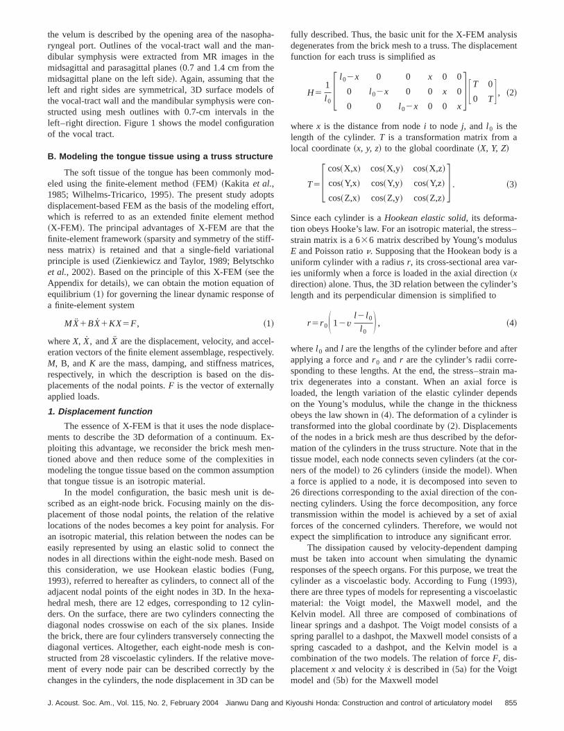
the velum is described by the opening area of the nasoryngeal port. Outlines of the vocal-tract wall and the madibular symphysis were extracted from MR images inmidsagittal and parasagittal planes~0.7 and 1.4 cm from themidsagittal plane on the left side!. Again, assuming that theleft and right sides are symmetrical, 3D surface modelsthe vocal-tract wall and the mandibular symphysis were cstructed using mesh outlines with 0.7-cm intervals inleft–right direction. Figure 1 shows the model configuratiof the vocal tract.
B. Modeling the tongue tissue using a truss structure
The soft tissue of the tongue has been commonly meled using the finite-element method~FEM! ~Kakita et al.,1985; Wilhelms-Tricarico, 1995!. The present study adoptdisplacement-based FEM as the basis of the modeling efwhich is referred to as an extended finite element met~X-FEM!. The principal advantages of X-FEM are that tfinite-element framework~sparsity and symmetry of the stiffness matrix! is retained and that a single-field variationprinciple is used~Zienkiewicz and Taylor, 1989; Belytschket al., 2002!. Based on the principle of this X-FEM~see theAppendix for details!, we can obtain the motion equation oequilibrium ~1! for governing the linear dynamic responsea finite-element system
MX1BX1KX5F, ~1!
whereX, X, andX are the displacement, velocity, and acceration vectors of the finite element assemblage, respectiM, B, andK are the mass, damping, and stiffness matricrespectively, in which the description is based on the dplacements of the nodal points.F is the vector of externallyapplied loads.
1. Displacement function
The essence of X-FEM is that it uses the node displaments to describe the 3D deformation of a continuum. Eploiting this advantage, we reconsider the brick mesh mtioned above and then reduce some of the complexitiemodeling the tongue tissue based on the common assumthat tongue tissue is an isotropic material.
In the model configuration, the basic mesh unit is dscribed as an eight-node brick. Focusing mainly on theplacement of those nodal points, the relation of the relalocations of the nodes becomes a key point for analysis.an isotropic material, this relation between the nodes caneasily represented by using an elastic solid to connectnodes in all directions within the eight-node mesh. Basedthis consideration, we use Hookean elastic bodies~Fung,1993!, referred to hereafter as cylinders, to connect all ofadjacent nodal points of the eight nodes in 3D. In the hehedral mesh, there are 12 edges, corresponding to 12 cders. On the surface, there are two cylinders connectingdiagonal nodes crosswise on each of the six planes. Inthe brick, there are four cylinders transversely connectingdiagonal vertices. Altogether, each eight-node mesh is cstructed from 28 viscoelastic cylinders. If the relative movment of every node pair can be described correctly bychanges in the cylinders, the node displacement in 3D ca
J. Acoust. Soc. Am., Vol. 115, No. 2, February 2004 Jianwu Dang and K
a--e
f-
e
-
rt,d
-ly.s,-
e--
n-inion
-s-eorbeen
e-
in-hedeen--ebe
fully described. Thus, the basic unit for the X-FEM analysdegenerates from the brick mesh to a truss. The displacemfunction for each truss is simplified as
H51
l 0F l 02x 0 0 x 0 0
0 l 02x 0 0 x 0
0 0 l 02x 0 0 xG FT 0
0 TG , ~2!
wherex is the distance from nodei to nodej, and l 0 is thelength of the cylinder.T is a transformation matrix from alocal coordinate~x, y, z! to the global coordinate~X, Y, Z!
T5F cos~X,x! cos~X,y! cos~X,z!
cos~Y,x! cos~Y,y! cos~Y,z!
cos~Z,x! cos~Z,y! cos~Z,z!G . ~3!
Since each cylinder is aHookean elastic solid, its deforma-tion obeys Hooke’s law. For an isotropic material, the stresstrain matrix is a 636 matrix described by Young’s moduluE and Poisson ration. Supposing that the Hookean body isuniform cylinder with a radiusr, its cross-sectional area vaies uniformly when a force is loaded in the axial direction~xdirection! alone. Thus, the 3D relation between the cylindelength and its perpendicular dimension is simplified to
r 5r 0S 12vl 2 l 0
l 0D , ~4!
wherel 0 andl are the lengths of the cylinder before and afapplying a force andr 0 and r are the cylinder’s radii corre-sponding to these lengths. At the end, the stress–straintrix degenerates into a constant. When an axial forceloaded, the length variation of the elastic cylinder depenon the Young’s modulus, while the change in the thickneobeys the law shown in~4!. The deformation of a cylinder istransformed into the global coordinate by~2!. Displacementsof the nodes in a brick mesh are thus described by the demation of the cylinders in the truss structure. Note that intissue model, each node connects seven cylinders~at the cor-ners of the model! to 26 cylinders~inside the model!. Whena force is applied to a node, it is decomposed into seve26 directions corresponding to the axial direction of the conecting cylinders. Using the force decomposition, any fotransmission within the model is achieved by a set of axforces of the concerned cylinders. Therefore, we wouldexpect the simplification to introduce any significant erro
The dissipation caused by velocity-dependent dampmust be taken into account when simulating the dynamresponses of the speech organs. For this purpose, we treacylinder as a viscoelastic body. According to Fung~1993!,there are three types of models for representing a viscoelamaterial: the Voigt model, the Maxwell model, and thKelvin model. All three are composed of combinationslinear springs and a dashpot. The Voigt model consists ospring parallel to a dashpot, the Maxwell model consists ospring cascaded to a dashpot, and the Kelvin model icombination of the two models. The relation of forceF, dis-placementx and velocityx is described in~5a! for the Voigtmodel and~5b! for the Maxwell model
855iyoushi Honda: Construction and control of articulatory model

tslidl.tht
uaa
ftexor
drorstioth
dcrethrersidnthisTr
hesfira
h.devaerrfaeadgn
lea
usoda
ntd;
ad in
is-sen-
herespa-romve
di-on-
0rieringueIn
lus
del.us.d
dtof 1.0pa-
eluiltesti-e.ithter,m--
nga-e ifdu-
isislon-
o
F5kx1bx, ~5a!
x5F/k1F/b, ~5b!
wherek andb denote the stiffness and viscous coefficienrespectively. The Voigt model is good for describing a sobody, while the Maxwell model is good for liquid materiaTherefore, we have adopted the Voigt model in modelingtongue tissue. Comparing~5! and ~1!, one can also see thathe Voigt model is easy to incorporate into the motion eqtion. When a force is applied on the Voigt model, a deformtion gradually builds up as the spring shares the load. Athe force is released, the dashpot displacement relaxes enentially, and the original length is restored from the defmation.
2. Volume of cylinders
As described above, a hexahedral mesh with eight noconsists of 28 cylinders. The tongue tissue is assembled f120 such hexahedral meshes. The volume of the cylindedetermined by the basic principle that the volume summaof the cylinders concerning a mesh must be equal tovolume of the mesh.
In the assembled meshes, a cylinder can be shareseveral adjacent meshes. In this case, the volume of theinder is assumed to distribute equally over the shameshes. Thus, the weight coefficient of a cylinder forrelevant meshes is equal to the reciprocal of the numbethe meshes sharing the cylinder. Among the 28 cylindthere are four cylinders connecting the diagonal nodes ina brick mesh, which are concerned with this mesh aloTherefore, their weight coefficients are 1.0 in calculatingvolume. The weight coefficient for the surface cylinders0.5 because they are shared by two adjacent meshes.weight coefficient is 0.25 for the edge cylinders that ashared by four adjacent meshes.
The length of each cylinder is calculated in terms of tnodal coordinates of the two ends. To calculate the crosectional area of the cylinders, the shape of a mesh isimagined as a uniform cylinder, whose length is the summtion of the weighted length of all cylinders of this mesThen, the cross-sectional area of the uniform cylinder istermined by the quotient of the mesh’s volume to the equilent length. As a result, the thickness of the inside cylindequals the cross-sectional area. The thickness for the sucylinders is the summation of half the cross-sectional arof two sharing meshes. Similarly, the thickness of the ecylinders is the summation of the weighted cross-sectioareas of four cylinder-sharing meshes.
In this model, the viscoelastic cylinder is the basic ement. The cylinder is a continuum that fully obeys physiclaws. To reduce the effects of the discreteness of the trstructure meshes, the Poisson ratio is also taken into accin the 3D meshes via a volume constraint that is describethe following section. Thus, this model can be thought ofa semicontinuum. This is one of the primary improvemefrom the previous version, where the meshes consistemass points and volumeless springs~Dang and Honda, 2001
856 J. Acoust. Soc. Am., Vol. 115, No. 2, February 2004 Jianwu Dan
,
e
--r
po--
esmisne
byyl-deofs,e
e.e
hee
s-st-
--sceseal
-ls-
untinssof
2002!. With this improvement, the mass matrix becomesconsistent matrix, instead of the lumped mass matrix usethe previous version.
3. Parameters and testing
In this study, the cylinder element is treated as a vcoelastic body. To describe the elastic properties, two estial parameters, Young’s modulusE and Poisson ration, areemployed. A damping property parameterb is also intro-duced to describe the viscous property.
The Young’s modulus influences the deformation of tbody in the direction of the force, which basically measuthe stiffness of the material. However, such mechanicalrameters reported in past studies, which were obtained fdifferent parts of the human body or from animals, hadiffered widely. Among them, Oka~1974! reported a valueof 300 kPa for a contracted muscle. Duck~1990! found avalue of 6.2 kPa for a human muscle under the rest contion, and a value of 110 kPa for the same muscle when ctracted. Minet al. ~1994! reported a Young’s modulus of 2kPa for the soft tissue of the vocal folds. Payan and Per~1997! used 15 kPa for the tongue tissue in their modelstudy, and values ranging from 15 to 250 kPa for the tongmuscles corresponding to different levels of contraction.this study, a value of 20 kPa is used for the Young’s moduin modeling the tongue tissue, following Minet al. ~1994!.For the viscosity, the viscous coefficient was 2 kPa•s, whichwas determined by a numerical experiment using this moThis value is about one-tenth that of the Young’s modulPoisson ration was set to 0.49, which is similar to that usein previous studies~Wilhelms-Tricarico, 1995; Payan anPerrier, 1997!. The soft tissue of the tongue is consideredpossess the same density as water. Therefore, a value og/cm3 was used for the density of tongue tissue. Theserameters are listed in Table I.
To verify the behaviors of the semicontinuum modwith the Poisson ratio, we applied a force on a cuboid bon the truss structure and compared the Poisson ratiomated from deformation of the cuboid with the original onIt was found that the estimated Poisson ratio varies wapplied forces. To reduce this artifact, one more paramethe ratio of the stress to the longitudinal strain, was eployed. Duck~1990! showed that the Young’s modulus depends to some extent on the ratio of the stress to the elotion, and is nearly constant for the soft tissue of the musclthe relative elongation is less than 20%. The Young’s molus exponentially increases when the elongation ratiolarger than 20%. Following Duck, the Young’s modulustreated as a constant of 20 kPa in this study when the e
TABLE I. Parameters used in the present model.
TongueTissue
Density Young’s modulus Viscosity Poisson rati1.0 g/cm3 20 kPa 2.0 kPa•s 0.49
Mandible Weight Young’s modulus Viscosity ¯
150 g 9.63106 kPa 9.63105 kPa•s ¯
Hyoid Weight Young’s modulus Viscosity ¯
Bone 5 g 9.63106 kPa 9.63105 kPa•s ¯
g and Kiyoushi Honda: Construction and control of articulatory model

ttho
te
heid
aionoreuue
joi
the
ed
oi
mthucts
ththesheoub
ribisf
su
her
n-od
g
meal
:
l-ol-he
s:idis
al-ec-80
ueMR
reer-
ajor
,
gi-
Thecalisofthe
cles
e.theanriorr-r-
he: theed.icthe
woarethethe
gation ratio is less than 20%, and its value increases aselongation ratio becomes larger. The increasing rate ofYoung’s modulus functions as a parameter to maintain a cstant Poisson ratio during tissue deformation.
The elongation-dependent Young’s modulus was demined using a viscoelastic cuboid with a size of 63332 cm3. The cuboid was divided into 53332 hexahedralmeshes and constructed using the truss structure. Whenplying forces on the cuboid in the longitudinal direction, tPoisson ratio was evaluated by the changes of the cubothe axial and perpendicular directions using formula~4!. Anelongation-dependent Young’s modulus was chosen to mtain the Poisson ratio around 0.49 while treating the cubeither as a brick-assembled body or as a single brick. Americal simulation was also conducted on the same cubby using ANSYS™ software, and the same behaviors weconfirmed. The simulation showed that the truss-structmodel based on X-FEM is sufficient for modeling the tongtissue.
Compared with the traditional FEM, there are two mabenefits of using this modeling. First, a fast computationachieved without significant loss in accuracy. Second,proposed model demonstrates excellent stability; no divgence was seen, even when a quite large force was loadwhen extreme deformation took place.
4. Volume constraint for tongue body
The tongue body is commonly considered to consistincompressible tissue. However, the cubic meshes lackcompressible properties in the above model. If no voluconstraint is taken into account, changes in the volume oftongue were about 5% during tongue deformation. To redthe changes, it is necessary to incorporate a constrainmaintain the volume of the tongue tissue. For this purpothe Lagrange function first comes to mind. However,constraint of the volume constancy introduced byLagrange function did not always work well; it sometiminterfered with tongue movement. One of the resulting pnomena, for example, was that on occasion the tongue cnot move in response to a small change in force. It mightthat the vectors for retaining constant volume are not distuted continuously over the multidimensional space consing of the nodes’ coordinates. For this reason, a procedureminimizing volume changes is introduced to reproduce tisincompressibility.
In the truss-structure model, the total volume of ttongue equals the summation of the volumes of all cylindeTherefore, minimizing the changes in volume for all cyliders can achieve a volume constraint on the tongue bWhen a force is applied on cylinderi in the axial direction,the change in the cylinder’s volume is
DVi~X!5pr 02l 02pr 0
2S 12nD l
l 0D 2
~ l 01D l !, ~6!
where the variation of the radius is represented by lenincrement D l and Poisson ration using ~4!. Using theHoubolt integration method~Bathe, 1996!, motion equation
J. Acoust. Soc. Am., Vol. 115, No. 2, February 2004 Jianwu Dang and K
hee
n-
r-
ap-
in
n-idu-id
re
rser-or
fn-eeetoe,ee
-lde-t-ore
s.
y.
th
~1! is rewritten in the finite difference expansions ofDX5B, whereD denotes the resultant matrix andB is the vec-tor consisting of known terms in~1!. The constraint is com-bined with the motion equation system by adding the voludifference and then minimizing the total error. Thus, the finsystem equations are derived from the following formula
]
]X F iDX2Bi21a(i
DVi~X!2G50, ~7!
wherea is the coefficient to adjust the tolerance of the voume changes in the tongue body. After introducing the vume constraint, the variation ratio of the volume of ttongue is reduced from about 5% to about 0.3%.
III. MUSCULAR STRUCTURE AND FORCEGENERATION
This model involves three kinds of external forcemuscle contraction, collision of the soft tissue with the rigboundaries, and gravitational force. Muscular contractionthe source force to drive the model. Gravitational forceways acts on all the nodes of the model in the vertical dirtion. The acceleration of gravity used in this model was 9dyne•cm/s2.
A. Modeling of muscles and rigid organs
The anatomical arrangement of the major tongmuscles was examined based on a set of high-resolutionimages obtained from the prototype speaker~Dang andHonda, 2001; 2002!. The boundaries of the muscles wefirst traced in each slice of the MR images, and then supimposed on each other so that the contours for the mmuscles could be identified. Thus, the genioglossus~GG! andgeniohyoid ~GH! were identified in the midsagittal planewhile the hyoglossus~HG! and styloglossus~SG! weremainly found in the parasagittal planes. The superior lontudinalis ~SL! and inferior longitudinalis~IL ! muscles wereseen in both the midsagittal and parasagittal planes.other intrinsic muscles such as the transversus and verticould not be identified in the MR images. The orientationthe tongue muscles was also examined with reference toliterature~Miyawaki, 1974; Warfel, 1993; Takemoto, 2001!.
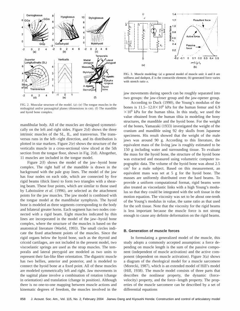
Figure 2 shows the arrangement of the tongue musused in the proposed model. Figure 2~a! shows the GG,which runs midsagittally in the central part of the tonguSince the GG is a triangular muscle, and different parts ofmuscle exert different effects on tongue deformation, it cbe functionally separated into three segments: the anteportion ~GGa! indicated by the dashed lines, the middle potion ~GGm! shown by the gray lines, and the posterior potion ~GGp! indicated by the dark lines. The thickness of tlines represents the approximate size of the muscle fibersthicker the line, the larger the maximum force generatFigures 2~b! and~c! show the arrangement of other extrinsmuscles, the HG and SG, in the parasagittal plane, wherethickest line represents the hyoid bone. In addition, ttongue-floor muscles, the geniohyoid and mylohyoid,also shown in the parasagittal planes. The top points ofmylohyoid bundles are attached to the medial surface of
857iyoushi Honda: Construction and control of articulatory model
tr
nsis
e5t
ee
awfi-senithoboc
hint
tn
twtet
cl
lei
ath
intoup.
9henyight
esealehebeateone
to-2.5an
Toreu-thenthsedmsongms.
isde-po-
erelat
p-et of
mandibular body. All of the muscles are designed symmecally on the left and right sides. Figure 2~d! shows the threeintrinsic muscles of the SL, IL, and transversus. The traversus runs in the left–right direction, and its distributionplotted in star markers. Figure 2~e! shows the structure of thverticalis muscle in a cross-sectional view sliced at thesection from the tongue floor, shown in Fig. 2~d!. Altogether,11 muscles are included in the tongue model.
Figure 2~f! shows the model of the jaw–hyoid boncomplex. The right half of the mandible is drawn in thbackground with the pale gray lines. The model of the jhas four nodes on each side, which are connected byrigid beams~thick lines! to form two triangles with a shearing beam. These four points, which are similar to those uby Laboissie`re et al. ~1996!, are selected as the attachmepoints for the jaw muscles. The jaw model is combined wthe tongue model at the mandibular symphysis. The hybone is modeled as three segments corresponding to theand bilateral greater horns. Each segment has two nodesnected with a rigid beam. Eight muscles indicated by tlines are incorporated in the model of the jaw–hyoid bocomplex, where the structure of the muscles is based onanatomical literature~Warfel, 1993!. The small circles indi-cate the fixed attachment points of the muscles. Sincerigid organs below the hyoid bone, such as the thyroid acricoid cartilages, are not included in the present model,viscoelastic springs are used as the strap muscles. Theporalis and lateral pterygoid are modeled as two unitsrepresent their fan-like fiber orientation. The digastric mushas two bellies, anterior and posterior, and is modeledconnect the hyoid bone at a fixed point. All of these muscare modeled symmetrically left and right. Jaw movementsthe sagittal plane involve a combination of rotation~changein orientation! and translation~change in position!. Althoughthere is no one-to-one mapping between muscle actionskinematic degrees of freedom, the muscles involved in
FIG. 2. Muscular structure of the model.~a!–~e! The tongue muscles in themidsagittal and/or parasagittal planes~dimensions in cm!. ~f! The mandibleand hyoid bone complex.
858 J. Acoust. Soc. Am., Vol. 115, No. 2, February 2004 Jianwu Dan
i-
-
h
ve
dt
iddy
on-nehe
hedom-oetosn
nde
jaw movements during speech can be roughly separatedtwo groups: the jaw-closer group and the jaw-opener gro
According to Duck~1990!, the Young’s modulus of thebones is 11.5– 12.03106 kPa for the human femur and 6.3106 kPa for the human tibia. In this study, we used tvalue obtained from the human tibia in modeling the bostructures, the mandible and the hyoid bone. For the weof the bones, Yamazaki~1933! investigated the weight of thecranium and mandible using 92 dry skulls from Japanspecimens. His result showed that the weight of the mjaws was around 90 g. According to this literature, tequivalent mass of the living jaw is roughly estimated to150 g including water and surrounding tissue. To evaluthe mass for the hyoid bone, the structure of the hyoid bwas extracted and measured using volumetric computerpographic data. The volume of the hyoid bone was aboutcm3 for a male subject. Based on this measurement,equivalent mass was set at 5 g for the hyoid bone. Themasses are uniformly distributed over the hard beams.provide a uniform computational format, rigid beams wealso treated as viscoelastic links with a high Young’s modlus so that they could be integrated with the soft tissue inmotion equation. The viscosity was set to be about one-teof the Young’s modulus in value, the same ratio as that ufor the soft tissue. Note that the viscosity for the rigid beais less important because the muscle force is not strenough to cause any definite deformation on the rigid bea
B. Generation of muscle forces
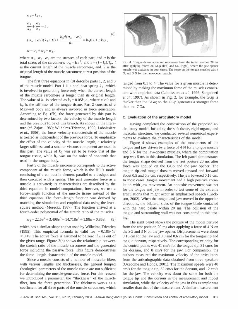
In formulating a generalized model of the muscle, thstudy adopts a commonly accepted assumption: a forcepending on muscle length is the sum of the passive comnent ~independent of muscle activation! and the active com-ponent~dependent on muscle activation!. Figure 3~a! showsa diagram of the rheological model for a muscle sarcom~Morecki, 1987!, which is an extended model of Hill’s mode~Hill, 1938!. The muscle model consists of three parts thdescribes the nonlinear property, the dynamic~force-velocity! property, and the force–length property. The proerties of the muscle sarcomere can be described by a sdifferential equations
FIG. 3. Muscle modeling:~a! a general model of muscle unit:k andb arestiffness and dashpot,E is the contractile element;~b! generated force varieswith stretch ratio«.
g and Kiyoushi Honda: Construction and control of articulatory model
th
3
thth
fnisgtra
leslyd
eat
tieanast
ethbas
s
ic
nate
epeiesoclsic
ter-is-
isorce
ar-nderi-
the
tiontesfterhe
ardcm.rre-
setme
itetede
est-
ed
utndforfortheorsers0m/sheodelsent
ms
as 4
s15k1«,
s2
k21
s2
b25 «,
~8!
~sm1s3!~k31E!1k3d~sm1s3!
dt5b3E«1Ek3«,
s5s11s21s3 ,
wheres1 , s2 , s3 are the stresses of each part, ands is thetotal stress of the sarcomere;sm5E«2, and«5( l 2 l 0)/ l 0 . lis the current length of the muscle sarcomere, andl 0 is theoriginal length of the muscle sarcomere at rest position oftongue.
The first three equations in~8! describe parts 1, 2, andof the muscle model. Part 1 is a nonlinear springk1 , whichis involved in generating force only when the current lengof the muscle sarcomere is longer than its original lengThe value ofk1 is selected ask150.05k0«, where«.0 andk0 is the stiffness of the tongue tissue. Part 2 consists oMaxwell body and is always involved in force generatioAccording to Eq.~5b!, the force generated by this partdetermined by two factors: the velocity of the muscle lenand the previous force of this branch. As shown in the liteture ~cf. Zajac, 1989; Wilhelms-Tricarico, 1995; Laboissie`reet al., 1996!, the force–velocity characteristic of the muscis treated as independent of the previous force. To emphathe effect of the velocity of the muscle length, a relativelarger stiffness and a smaller viscous component are usethis part. The value ofk2 was set to be twice that of thtongue tissue, whileb2 was on the order of one-tenth thused in the tongue body.
Part 3 of the muscle sarcomere corresponds to the accomponent of the muscle force, which is the Hill’s modconsisting of a contractile element parallel to a dashpotthen cascaded with a spring. This part generates forcemuscle is activated; its characteristics are described bythird equation. In model computations, however, we usforce–length function of the muscle tissue instead ofthird equation. The force–length function was derivedmatching the simulation and empirical data using the lesquare method~Morecki, 1987!. The function arrived at afourth-order polynomial of the stretch ratio of the muscle
s3522.5«413.498«3214.718«211.98«10.858, ~9!
which has a similar shape to that used by Wilhelms-Tricar~1995!. This empirical formula is valid for20.185,«,0.49. The active force is assumed to be zero if« is out ofthe given range. Figure 3~b! shows the relationship betweethe stretch ratio of the muscle sarcomere and the generforce including the passive force. This figure demonstrathe force–length characteristic of the muscle model.
Since a muscle consists of a number of muscular fibwith various lengths and thicknesses, the general lumrheological parameters of the muscle tissue are not sufficfor determining the muscle-generated force. For this reawe introduced a parameter, the ‘‘thickness’’ of the musfiber, into the force generation. The thickness works acoefficient for all three parts of the muscle sarcomere, wh
J. Acoust. Soc. Am., Vol. 115, No. 2, February 2004 Jianwu Dang and K
e
.
a.
h-
ize
in
velda
heaeyt-
o
teds
rsdntn,eah
ranged from 0.1 to 4. The value for a given muscle is demined by making the maximum force of the muscles constent with empirical data~Laboissiere et al., 1996; Sanguinetiet al., 1997!. As shown in Fig. 2, for example, the GGpthicker than the GGa; so the GGp generates a stronger fthan the GGa.
C. Evaluation of the articulatory model
Having completed the construction of the proposedticulatory model, including the soft tissue, rigid organs, amuscular structure, we conducted several numerical expments to evaluate the characteristics of the model.
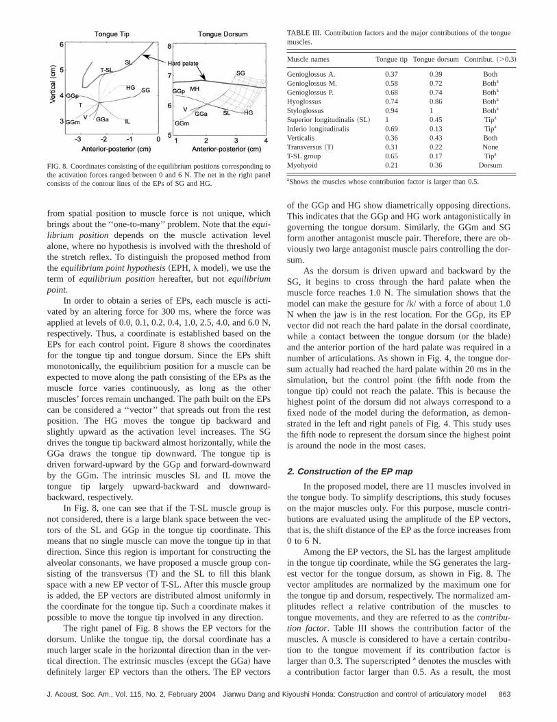
Figure 4 shows examples of the movements oftongue and jaw driven by a force of 4 N for a tongue muscleand 3 N for the jaw-opener muscles, where the computastep was 5 ms in this simulation. The left panel demonstrathe tongue shape derived from the rest posture 20 ms aforce was applied on the GGp and the jaw opener. Ttongue tip and tongue dorsum moved upward and forwabout 0.5 and 0.3 cm, respectively. The jaw lowered 0.16In most cases, tongue movement had a high positive colation with jaw movement. An opposite movement wasfor the tongue and jaw in order to test some of the extrearticulations that might occur in emphasized speech~Erick-son, 2002!. When the tongue and jaw moved in the opposdirections, the bilateral sides of the tongue blade contacwith the hard palate within 20 ms. The collision of thtongue and surrounding wall was not considered in this ting.
The right panel shows the posture of the model derivfrom the rest position 20 ms after applying a force of 4 N onthe SG and 3 N on the jawopener. Displacements were abo0.16 cm for the jaw and 0.8 and 0.6 cm for the tongue tip atongue dorsum, respectively. The corresponding velocitythe control points was 41 cm/s for the tongue tip, 31 cm/sthe dorsum, and 8 cm/s for the jaw. For comparison,authors measured the maximum velocity of the articulatfrom the articulographic data obtained from three speak~Okadome and Honda, 2001!. The maximum speeds were 4cm/s for the tongue tip, 32 cm/s for the dorsum, and 12 cfor the jaw. The velocity was about the same for both ttongue tip and the dorsum in the measurement and msimulation, while the velocity of the jaw in this example wasmaller than that of the measurement. A similar measurem
FIG. 4. Tongue deformation and movement from the initial position 20after applying forces on GGp~left! and SG~right!, where the jaw-openermuscle was activated in both cases. The force on the tongue muscles wN, and 3 N for the jaw-opener muscle.
859iyoushi Honda: Construction and control of articulatory model

soenumgune2
awcmre
emveod
thf
nggcas,oin
rnoa
tthtsare
tu
onibl oasithcuthn
e,
thethe
n
ity.tionion-en
anal-xi-osa,and
heand
ro-derhetheater,eout
40eor
eon.ceionte
ghtandr-iond onscle
in the literature~Stevens, 2000! is cited in Table II and wasused to evaluate the model simulation. The comparishowed that our simulation of the velocities was consistwith those results for the tongue tip and the tongue dors
In Fig. 4, one can see that the meshes in the tondemonstrated well-balanced deformation. In the right pathe tongue dorsum made a closure with the palate withinms, and the closure was maintained well until the jreached its stationary position with an approximately 1.0-aperture. The same test was also conducted in some extcases of applying a large force of 7 N on anumber of tonguemuscles. For the given forces, the tongue had some extrdeformations, but the deformation was smooth and no digence was seen. In these evaluations, the proposed mdemonstrated excellent performance on both static andnamic behaviors.
D. Collision of the tongue and the vocal-tract wall
In speech articulation, the tongue often contactsteeth, hard palate, and jaw as it moves. The tongue tip,example, collides with the vocal-tract wall when produciconsonants such as /t/ and /l/. The lateral parts of the toncontact the hard palate to form a narrow airway of the votract in producing the vowel /i/ or alveolar fricatives. Thuthe contact of the tongue with the vocal-tract wall is onethe important factors in achieving accuracy and stabilitythe dynamic control of the tongue. It also generates exteforces that affect tongue deformation when the contactcurs. Therefore, the realization of tongue–wall contact isessential task for a physiological articulatory model.
Since the shape of the vocal-tract wall is too complexbe described by an analytic function, the contact oftongue with the vocal-tract wall, unlike the other constraincannot be combined into the motion equations systemcally. As an alternative, we propose a method with thsteps to deal with the contact between the tongue andtract wall to check whether or not the nodes of the tongcross through the tract wall; find the equilibrium positionthe wall for the nodes outside of the vocal tract, and distrute the collision force. If a node crosses through the walthe vocal tract during articulation, its trajectory must haveintersection with the tract wall. Since the tract wall was asembled by triangle planes, we first identify the plane wwhich the trajectory intersected on the wall and then callate the collision force of the node when it is bounded onwall. The following formula is used to estimate the collisioforce:
TABLE II. Comparison of the velocities~cm/s! of the tongue tip, tonguedorsum, and mandible obtained from simulation and observations.
Tongue tip Tongue dorsum Mandible
Model 41 30~18!b 8EMMA 40 32 ~22!b 12
Stevens~2000!a 32 15b¯
aMeasured from the figures~Stevens, 2000!.bVertical movement alone.
860 J. Acoust. Soc. Am., Vol. 115, No. 2, February 2004 Jianwu Dan
nt.el,0
me
er-dely-
eor
uel
f
alc-n
oe,ti-ehee
-fn-
-e
f x5(i
~kiD l xi1biD l xi /h!, ~10!
wherei is the index of the cylinders connected to the nodandh is the computation step.ki andbi are the stiffness andviscous coefficients of cylinderi. D l xi is the increment ofcylinder i in thex dimension caused by the wall bounding.f x
is thex component of the resultant bounded force. Usingsame approach, the force can be calculated fory-dimensionf y andz-dimensionf z . To reach an equilibriumposition on the wall, the coordinates~x, y, andz! of the nodemust meet the following simultaneous equations:
A~x2px!1B~y2py!1C~z2pz!50,
a~x2px!5 f x ,~11!
a~y2py!5 f y ,
a~z2pz!5 f z ,
wherepx , py , andpz are the coordinates of the intersectioon the plane;A, B, andC are the norm of the plane; anda isan unknown equivalent factor of the stiffness and viscosSince such a deformation cannot be predicted in the moequations, the collision forces must be considered additally. In model calculation, the collision force above is takinto account at the next computation step as an input.
When the tongue slides on the wall surface to reachequilibrium position, friction between the tongue and the pate is a considerable factor. This friction can be appromated as the force generated in laminar flows of the mucsince there is much mucosa on the surfaces of the tonguethe hard palate. Such a friction force is proportional to tviscosity of mucosa, the contact area between the tonguepalate, and the velocity of the tongue, but is inversely pportional to the thickness of the mucosa. To obtain the orof the magnitude for such friction, we roughly estimate tfriction force based on the following conditions. Supposemucosa has about the same viscous coefficient as wwhich is 0.01 dyne•s/cm2 at 20 °C, and the thickness of thmucosa between the tongue and palate is very thin, ab0.01 cm. The maximum velocity of the tongue is aboutcm/s ~see Table II!. Under the given conditions, the forccaused by the friction for a unit area is about 40 dynes,431024 N. This friction force is much smaller than thforces caused by muscle contraction and wall reactiTherefore, this friction is ignored at the current model. Sinthe friction can be expected to stabilize the tight constrictto some extent, it may be helpful in achieving accuracontrol.
IV. ESTIMATION OF MUSCLE FUNCTION BY MODELSIMULATIONS
As stated in the Introduction, many studies have souto ascertain the relationship between tongue movementmuscle activation. However, it is generally difficult to detemine such a relationship from experimental observatalone because critical parameters such as mechanical loaa muscle cannot be observed. This section examines mufunctions using model simulations.
g and Kiyoushi Honda: Construction and control of articulatory model

lln-
FIG. 5. Starting point region of thetongue tip, shown by the pale smacircles, and the ending points driveby a force of 4 N with a 150-ms duration, shown by the dark crosses.
lasd
vina
engunoro
t.clGc
toilt
, asfer-
gwasasa-all
clehen-
tippe-aioneertiptipardtip
ishas
A. Muscle activations and tongue movements
In order to evaluate tongue muscle functions by simution, tongue movements are represented using two pointthe tongue tip and the tongue dorsum, which are referreas thecontrol points~Dang and Honda, 2001; 2002!.
1. Function of tongue muscles
In producing an utterance, the tongue can start its moment from many different positions or shapes. The comdeformation of the tongue involves all of the past deformtions and/or the history of the muscle forces to some extTo account for the effects of the past deformations on tonbehaviors, a scattered region of starting points was desigfor the control points, based on observations obtained frthe prototype speaker of the model using the x-ray micbeam system~Hashi et al., 1998!. The control points werefirst moved from the initial position to a given starting poinThe initialization movements were governed by four muscombinations: GGp–GGm–GGa, GGp–SG–GGa, HGGm–GGa, and HG–SG–GGa. Activation forces for eamuscle were set to be six levels between 0 and 6.0 newwith a 120-ms duration. Nonlinear intervals were adoptedthe six levels to achieve a uniform distribution. As a resu
J. Acoust. Soc. Am., Vol. 115, No. 2, February 2004 Jianwu Dang and K
-ofto
e-g-t.eedm-
e–hnsn,
864 starting points were generated for each control pointshown by the small gray circles in Figs. 5 and 6 as a reence.
After the control points arrived at the given startinpoints, all forces were released and then the tongue bodydriven by a specific muscle with a given force. The force w4 N with a 150-ms duration. Figure 5 plots the ending loctions of the tongue tip, shown by the dark crosses. The smgray circles show the starting points, and the large cirdenotes the initial location of the control point. Note that tboundary and contact force of the tract wall were not cosidered in estimating the muscle functions.
As shown in this figure, even though the tonguestarted from widely scattered points, it converges to a scific, small region for all of the muscles. When the GGcontracts, the tongue tip concentrates to a strip of a regthat is lower than the initial position, shown by the largcircle. This means that the function of the GGa is to lowthe tongue tip. Similarly, the GGm moves the tongueforward and downward, while the GGp drives the tongueforward and upward. The HG moves the tongue tip backwand slightly upward. The SG mainly drives the tonguebackward, where the convergence region for the SGsmaller than that of the others. This implies that the SG
lls
FIG. 6. Starting point region of thetongue dorsum, shown by the smagray circles, and the ending pointdriven by a force of 4 N with a 150-msduration, shown by the dark crosses.
861iyoushi Honda: Construction and control of articulatory model

is
ar
oi
anm
ntiorinitt-r
-taun
thudi
tanntioTrcn
rinduth
icegeie
troodtrtlon
esos
yonaw
em-els
tra-ntnt
henthen a
theedif-de-
.hethensthetllyiumen
isar-ec-
pastn ace
h ascleing
N.
a clearer equilibrium position for the tongue tip, or that thequilibrium position is reached faster than the others.
For the intrinsic muscles, the inferior longitudinalis~IL !has a definite function that moves the tongue tip backwand downward, while the superior longitudinalis~SL! drivesthe tongue tip upward and backward. The verticalis~V!moves the tongue tip downward. The transversus~T! andmylohyoid ~MH! did not show any definite contribution tmovement of the tongue tip. The geniohyoid is not shownthe figure because its contribution to both the tongue tipthe dorsum was small, or underestimated in the model silation.
Figure 6 shows the scattering of the starting points aending locations for the tongue dorsum, where the simulacondition was the same as that for Fig. 5. Among the extsic muscles, the GGm, GGp, HG, and SG show definfunctions that drive the dorsum to go front-lower, fronupper, back-lower, and back-upper, respectively. Thesesults are consistent with the findings in previous studies~cf.Baer et al. 1988!, while the GGa did not show any significant effect on the dorsum movement. The MH has a cereffect on the tongue body, which drives the tongue dorsupward and forward. The verticalis moves the dorsum dowward and forward to a certain extent, while the IL movesdorsum backward and upward. The SL moves the dorsslightly backward and downward, while the transversusnot show any contribution to the dorsum movement.
Putting Figs. 5 and 6 together, one can see that whenHG is activated the tongue dorsum moves backwarddownward, while the tongue tip moves backward aslightly upward. This suggests that an accompanying rotaof the tongue body takes place during such movements.above simulation shows that when the same muscle foare applied on the tongue, the control point from differestarting positions converges to a region but not a point duthe given duration. Since the duration is close to vowelration in speech with a normal rate, this suggests thatobserved vowel target regions in the electromagnetic artlographic data~cf. Danget al., 2002! may be a consequencof tongue biomechanics. The simulation results also sugthat the tongue muscles may need a longer time to achtheir equilibrium position.
2. Muscle forces and equilibrium position
The results plotted in Figs. 5 and 6 show that the conpoints were driven to arrive at specific regions in spitetheir widespread starting points. For the purpose of mocontrol, we consider two issues. One is whether the conpoints equilibrate at one point or converge to a sufficiensmall region when the activation duration is sufficiently prlonged. The other is whether the relationship betweemuscle force and an equilibrium position is unique.
A numerical experiment was conducted to answer thtwo questions. Four starting points were generated by fmuscle combinations with a force of 5.0 N for all muscleThe tongue was then driven from the starting points bspecific muscle with a 400-ms duration. The activatiforces were 1.0, 2.0, 3.5, and 5.0 N. This simulation wcarried out on all of the tongue muscles. Figure 7 sho
862 J. Acoust. Soc. Am., Vol. 115, No. 2, February 2004 Jianwu Dan
d
ndu-
dn-e
e-
inm-
emd
hed
dn
heestg-e
u-
stve
lfeloly-a
eur.a
ss
examples for three extrinsic muscles. The upper panels donstrate the results for the tongue tip, and the lower panare for the tongue dorsum. For each starting point, thejectories of the control points spread out along differepaths corresponding to the force levels. For differemuscles, the trajectories have dissimilar curvatures. Wactivating the GGp, for example, both the tongue tip anddorsum tended to reach force-dependent locations istraight path. In the cases of the GGm on the dorsum andSG on the tongue tip, the control points move along curvpaths from the starting points to the final locations. The dference between the paths is mainly caused by previousformation ~starting point! and/or the history of the forcesHowever, they finally converge at one point, where tmodel reaches an equilibrium state. In the simulation,control points generally reach their equilibrium positiowithin about 300 ms. These final points are referred to asequilibrium positionshereafter. It is interesting to find thathe equilibrium position of each muscle shifts monotonicaas the force level increases. This means that the equilibrposition and the force level have a unique relation for a givmuscle.
B. Mapping between equilibrium position andarticulatory target
In order to control the model via the muscle forces, ituseful to find a mapping between the muscle forces andticulatory targets. Such a mapping is constructed in this stion based on the equilibrium positions.
1. Equilibrium positions of muscles
As shown in Fig. 7, the equilibrium position~EP! foreach muscle corresponds to its activation level, despitedeformations. This relation provides a connection betweemuscle force and a spatial point in the articulatory spawhich is invariant for a given muscle structure. Using succonnection, a unique mapping can be obtained from a muforce to a spatial position. However, the inverse mapp
FIG. 7. Trajectories of the tongue tip~upper! and the dorsum~lower! fromdistinct starting points~indicated by squares! to certain ultimate locations~shown by circles! that correspond to the force levels of 1, 2, 3.5, and 5
g and Kiyoushi Honda: Construction and control of articulatory model
ch
eo
o
caNt
tehbe
theEenShi
rdherd
iv
hithheco
uis
.hese
to
s.in
SGob-
or-
hethethe
1.0P
ate,
in aor-the
theo aon-sesoint
inestri-ors,rom
dearg-heforam-to
eibu-ishost
gan
ue
from spatial position to muscle force is not unique, whibrings about the ‘‘one-to-many’’ problem. Note that theequi-librium position depends on the muscle activation levalone, where no hypothesis is involved with the thresholdthe stretch reflex. To distinguish the proposed method frtheequilibrium point hypothesis~EPH,l model!, we use theterm of equilibrium positionhereafter, but notequilibriumpoint.
In order to obtain a series of EPs, each muscle is avated by an altering force for 300 ms, where the force wapplied at levels of 0.0, 0.1, 0.2, 0.4, 1.0, 2.5, 4.0, and 6.0respectively. Thus, a coordinate is established based onEPs for each control point. Figure 8 shows the coordinafor the tongue tip and tongue dorsum. Since the EPs smonotonically, the equilibrium position for a muscle canexpected to move along the path consisting of the EPs asmuscle force varies continuously, as long as the otmuscles’ forces remain unchanged. The path built on thecan be considered a ‘‘vector’’ that spreads out from the rposition. The HG moves the tongue tip backward aslightly upward as the activation level increases. Thedrives the tongue tip backward almost horizontally, while tGGa draws the tongue tip downward. The tongue tipdriven forward-upward by the GGp and forward-downwaby the GGm. The intrinsic muscles SL and IL move ttongue tip largely upward-backward and downwabackward, respectively.
In Fig. 8, one can see that if the T-SL muscle groupnot considered, there is a large blank space between thetors of the SL and GGp in the tongue tip coordinate. Tmeans that no single muscle can move the tongue tip indirection. Since this region is important for constructing talveolar consonants, we have proposed a muscle groupsisting of the transversus~T! and the SL to fill this blankspace with a new EP vector of T-SL. After this muscle grois added, the EP vectors are distributed almost uniformlythe coordinate for the tongue tip. Such a coordinate makepossible to move the tongue tip involved in any direction
The right panel of Fig. 8 shows the EP vectors for tdorsum. Unlike the tongue tip, the dorsal coordinate hamuch larger scale in the horizontal direction than in the vtical direction. The extrinsic muscles~except the GGa! havedefinitely larger EP vectors than the others. The EP vec
FIG. 8. Coordinates consisting of the equilibrium positions correspondinthe activation forces ranged between 0 and 6 N. The net in the right pconsists of the contour lines of the EPs of SG and HG.
J. Acoust. Soc. Am., Vol. 115, No. 2, February 2004 Jianwu Dang and K
lf
m
ti-s,
hes
ift
her
PsstdGes
-
sec-sat
n-
pnit
ar-
rs
of the GGp and HG show diametrically opposing directionThis indicates that the GGp and HG work antagonisticallygoverning the tongue dorsum. Similarly, the GGm andform another antagonist muscle pair. Therefore, there areviously two large antagonist muscle pairs controlling the dsum.
As the dorsum is driven upward and backward by tSG, it begins to cross through the hard palate whenmuscle force reaches 1.0 N. The simulation shows thatmodel can make the gesture for /k/ with a force of aboutN when the jaw is in the rest location. For the GGp, its Evector did not reach the hard palate in the dorsal coordinwhile a contact between the tongue dorsum~or the blade!and the anterior portion of the hard palate was requirednumber of articulations. As shown in Fig. 4, the tongue dsum actually had reached the hard palate within 20 ms insimulation, but the control point~the fifth node from thetongue tip! could not reach the palate. This is becausehighest point of the dorsum did not always correspond tfixed node of the model during the deformation, as demstrated in the left and right panels of Fig. 4. This study uthe fifth node to represent the dorsum since the highest pis around the node in the most cases.
2. Construction of the EP map
In the proposed model, there are 11 muscles involvedthe tongue body. To simplify descriptions, this study focuson the major muscles only. For this purpose, muscle conbutions are evaluated using the amplitude of the EP vectthat is, the shift distance of the EP as the force increases f0 to 6 N.
Among the EP vectors, the SL has the largest amplituin the tongue tip coordinate, while the SG generates the lest vector for the tongue dorsum, as shown in Fig. 8. Tvector amplitudes are normalized by the maximum onethe tongue tip and dorsum, respectively. The normalizedplitudes reflect a relative contribution of the musclestongue movements, and they are referred to as thecontribu-tion factor. Table III shows the contribution factor of thmuscles. A muscle is considered to have a certain contrtion to the tongue movement if its contribution factorlarger than 0.3. The superscripteda denotes the muscles wita contribution factor larger than 0.5. As a result, the m
toel
TABLE III. Contribution factors and the major contributions of the tongmuscles.
Muscle names Tongue tip Tongue dorsum Contribut.~.0.3!
Genioglossus A. 0.37 0.39 BothGenioglossus M. 0.58 0.72 Botha
Genioglossus P. 0.68 0.74 Botha
Hyoglossus 0.74 0.86 Botha
Styloglossus 0.94 1 Botha
Superior longitudinalis~SL! 1 0.45 Tipa
Inferio longitudinalis 0.69 0.13 Tipa
Verticalis 0.36 0.43 BothTransversus~T! 0.31 0.22 NoneT-SL group 0.65 0.17 Tipa
Myohyoid 0.21 0.36 Dorsum
aShows the muscles whose contribution factor is larger than 0.5.
863iyoushi Honda: Construction and control of articulatory model

rshribr-
oitethtsb
e
ath
nt. Tse
a
isesthif
this
dmnbthaakth
leangthvaGh
erpe
tho
d
n
t
firstx.oflly,thejaw
o-as
innson,EPthe
owsjaws noe aPpti-ap
isthemic
theas
av-for
EPan-the
es,jaw,ge
ndjaw.12outso
extrinsic muscles~except the GGa! have larger power oveboth the tongue tip and tongue dorsum. Among the intrinmuscles, the SL and IL show definite contributions to ttongue tip. The transversus demonstrates a certain conttion when it is grouped with the SL, which plays an impotant role in increasing the control freedom. The geniohyshowed no significant contribution to any control point. Nothat this study only used two specific points to evaluatecontribution of the muscles. If different observation poinwere adopted, a dissimilar contribution factor might be otained for some muscles, e.g., the geniohyoid.
To develop a control method, it is necessary to reinspthe EP vectors based on the contribution and the freedommodel control. All of the EP vectors shown in Fig. 8 havecontribution factor larger than 0.3. In the coordinates oftongue tip, the GGa and verticalis~V! have a similar vectorwith smaller amplitude. These two vectors are taken iaccount because they increase the degree of the freedomtransversus~T! is also taken into account because it increathe degree of freedom, although its role is not explicit in2D representation.
In the dorsal coordinate, the EP vector of the MHlocated in the space between GGp and SG and contributwidening the area of contact between the dorsum andpalate, which is required for generating /k/ gestures with dferent contexts. For this reason, the MH is included indorsal coordinate for the control, although its vectorsmaller than that of the extrinsic muscles. The GGa anhave a similar EP vector to that of the GGm, but their aplitude is about half that of the GGm. These muscles areconsidered an independent factor in the control methodcause they neither contribute significantly nor increasedegree of freedom. For the same reason, the SL is not treas an independent factor. However, these muscles are tinto account in the muscle co-contraction, described insubsequent section.
Based on the above consideration, five major muscare taken into account in controlling the tongue dorsum,nine muscles and one muscle group are used for the tontip. Thus, the mapping between the spatial points andmuscle forces can be obtained based on the selected EPtors. An example is shown in the right panel of Fig. 8 bycontour net, which consists of the EPs of the SG and HThe contour lines correspond to the six force levels. Sucnet of contour lines is named theequilibrium position map~EP map!. With the EP map, any arbitrary point inside thregion of the map can be reached using the forces intelated from the contour lines. The primary difference betwethe EP map and the EPH~l model! is that the EP map is astraightforward mapping between muscle forces andequilibrium positions of the articulators, while the EPH nonly requires a muscle loading function but also thel com-mands that are involved in a hypothesis on the thresholthe stretch reflex.
3. EP map of the tongue vs jaw positions
Since there is a high correlation between the movemeof the tongue and jaw, the coordinate system consistingthe EPs depends strongly on the jaw position. To examine
864 J. Acoust. Soc. Am., Vol. 115, No. 2, February 2004 Jianwu Dan
iceu-
d
e
-
ctof
e
ohes
toe
-e
V-ote-e
tedene
sdueeec-
.a
o-n
et
of
tsofhe
relationship between the EP maps and jaw positions, weinvestigated the equilibrium position of the jaw compleFive forces of 0.5, 1.2, 2.5, 4.0, and 6.0 N with a duration300 ms were applied to the jaw-opener muscle individuaand three forces of 0.5, 1.5, and 3.0 N were applied tojaw-closer muscle. Corresponding to the forces on theopener, the jaw achieved EPs of20.16, 20.37, 20.76,21.10, and21.42 cm, where the minus sign denotes a psition lower than the rest position. When the jaw closer wactivated, the jaw reached EPs of 0.09, 0.21, and 0.47 cmthe close direction. Altogether, nine equilibrium positiowere obtained for the jaw, which includes one rest positifive opener positions, and three closer positions. Themaps for the tongue were constructed corresponding tonine positions of the jaw.
Comparison of the nine jaw-dependent EP maps shthat the entire EP map rotates and translates with themovement, but the detailed structures of the EP maps hadefinite changes. This suggests that it is possible to derivdynamicEP map for any arbitrary jaw position from one Emap by means of translation and rotation. To obtain an omal dynamic EP map for all the jaw positions, the EP mgenerated by applying 0.5 N on the jaw-opener musclechosen as the typical one, since it is the neutral one innine positions. Figure 9 shows an example using a dynaEP map~the thin lines! derived from the typical EP map torepresent the EP map~the thick lines! of the jaw opener with2.5 N. The rotation degree for the dorsal coordinate wassame as that of the jaw, while a slight inverse rotation wcarried out for the tongue tip. In this representation, theerage difference between the two EP maps was 0.049 cmthe tongue tip and 0.041 cm for the dorsum.
The accuracy of representing the jaw-dependentmaps by the typical EP map was evaluated by a mesquared error between the derived dynamic EP maps andoriginal ones. Table IV shows the evaluation for all caswhere the top corresponds to the closed positions of theand the bottom to the wide-open jaw position. The averaerror over all jaw positions is 0.043 cm for the tongue tip a0.034 cm for the dorsum. The error increases as thedeviates from the reference position. The largest error of 0cm occurred for the tongue tip when the jaw opened ab1.8 cm. For almost all articulations, the tongue tip is not
FIG. 9. Example of using a dynamic EP map~the thin lines! derived fromthe typical EP map of the jaw opener at 0.5 N to represent the EP map~thethick lines! of the jaw opener at 2.5 N.
g and Kiyoushi Honda: Construction and control of articulatory model

reciaEPhis
byle
atthtwasaclathuu
r,nd
vg
ra1
Thdndte
upelecanuimao
theittheGpthe
onIL.
nt-ardunc-aire-this
fer-ago-
ns.a
hatgueoo-
thesiceen
an-reofanin-first
a-
SL
crucial when the jaw opens wide. In other words, this repsentation does not introduce any significant error for crupoints. Figure 9 and Table IV illustrate that a dynamicmap can be obtained effectively for any jaw position via tderivation.
V. CO-CONTRACTION OF MUSCLES BASED ON THEEP MAP
The most effective way to form a tongue shapemuscle contraction, in view of the minimal energy principis for two agonist muscles to work together to achievegiven target. Thus, the muscle forces can be easily estimvia the EP map shown in Fig. 8. During speech, however,situation is much more complicated because more thanagonist muscles can work together to reach a target,some agonist–antagonist muscles can co-contract at thetime. To simulate this situation, we designed 17 two-musgroups and seven three-muscle groups for the tongue tipfive two-muscle groups and one three-muscle group fordorsum. An example of the EP map for the two-muscle grois shown in the right panel of Fig. 8. The three-muscle groconsists of an independent muscle and a muscle paiwhich the activation of the independent muscle correspoto the co-contraction level and governs amain part of thetongue, while the muscle pair manipulates the other partthe mechanism of co-contraction of the agonist and antanist muscles.
A. Co-contraction between agonist and antagonist
Eight three-muscle groups were designed to genesome potential co-contractions during speech. Figureshows the co-contractions for two three-muscle groups.thick dark lines show a part of the EP vectors of the coornates, which were generated by activating the muscles ividually. The thin dark lines and the thin gray lines denothe EP trajectories for two synergistic muscles in the grorespectively. The attachment of the thin lines on the EP vtor of the independent muscle, indicated by the open circcorresponds to activation levels of the independent musAs shown in the upper panels, the combination of the SGthe muscle group of the GGp and SL can move the dorstoward the palatal target by the SG and at the same tcontrol the tongue tip to an apical target by the muscle pThis mechanism can reach a compatible target set for b
TABLE IV. Differences between derived and original EP maps.
Status ofthe jaw
Force on thejaw muscle~N!
Position on theinitial ~cm!
Errors for theapex~cm!
Errors for thedorsum~cm!
Closer 3.0 0.407 0.037 0.030Closer 1.5 0.210 0.026 0.024Closer 0.5 0.090 0.021 0.020Initial 0.0 0.00 0.024 0.019
Openera 0.5 20.160b 0.000 0.000Opener 1.2 20.374 0.021 0.018Opener 2.5 20.761 0.049 0.041Opener 4.0 21.097 0.084 0.066Opener 6.0 21.425 0.123 0.091
aIndicates the typical EP map.bThe minus denotes jaw positions lower than the rest position.
J. Acoust. Soc. Am., Vol. 115, No. 2, February 2004 Jianwu Dang and K
-l
,aedeo
ndmeendeppins
iao-
te0e
i-i-
,c-s,le.d
me
ir.th
the tongue tip and the dorsum. It is interesting to find thatmuscle pair works in synergy for the tongue tip whilefunctions as an antagonist pair for the tongue dorsum. Ifproper force ratio is chosen for the muscle pair of the Gand SL, the dorsum can be kept in a given position whentongue tip position is manipulated, and vice versa.
The lower panels in Fig. 10 show the co-contractibetween the GGp and the muscle pair of the GGa andThis muscle group drives the dorsum to move in a froupper direction and governs the tongue tip to go downwand backward. The muscle pair demonstrates the same ftion as that in the upper panel, in which the muscle pshows a synergetic function for the tongue tip while it bhaves as an antagonist pair for the tongue dorsum. Usingcombination, the tongue tip can be retracted without interence to the dorsum because the GGa and IL work as antnists for the dorsum.
Figure 11 shows other examples of the co-contractioIn the upper panels, the combination of the GGm andmuscle pair of the SL and T-SL demonstrates a function tproduces a posture with a lower dorsum and a higher tontip. The tongue tip is governed by the muscle pair of twintrinsic muscles, SL and T-SL, and an optimal dorsum psition can be maintained by using a proper force ratio formuscle pair. Compared to the other cases, the intrinmuscles have a smaller effect on the dorsum. It can be sthat the intrinsic muscle pair also definitely works as antagonist pair for the dorsum. The lower panels of the figushow a different combination, the T-SL and a muscle pairthe GGm and HG, in which the independent muscle isintrinsic muscle, and the muscle pair consists of two extrsic muscles. In contrast to the other groups, this groupgoverns the tongue tip by the intrinsic muscle and then m
FIG. 10. Co-contractions of the SG and a muscle pair of the GGp and~upper panels!, and of the GGp and a muscle pair of the GGa and IL~lowerpanels!.
865iyoushi Honda: Construction and control of articulatory model

twfo
rka
ast
mcofd.
iredrathot
sc
Grti
powphn
cletheupset.
na-
et.dif-ereran-llyheted
sets.
s.ns,thethetheet isforthefor
an-ive
s
ets
ent,enthethehe-
-S
s ofTheicate
nipulates the dorsum by the extrinsic muscles, where theextrinsic muscles function as an antagonist muscle pairthe tongue tip.
In all of the three-muscle groups, the muscle pair woin synergy for one part of the tongue while behaving asantagonist pair for the other part. This function can increthe degree of the freedom for model control, allowing uscontrol different parts of the tongue independently to soextent. Because of this property, we might say that thecontraction can also be used to maintain the stability okinematic system when part of the system is manipulate
B. Realization of multiple features using co-contraction mechanism
Generally, in a target vector, only one crucial featuredecisive in forming the phoneme, where the other featuare referred to asindecisivefeatures. To produce a plannesound, the accuracy of the crucial feature must be guateed, while an optimal achievement is also desired forindecisive features. This requires us to deliberate over mthan one feature at the same time to find a force set thaoptimal for the concerned target features. Figure 12 showexample of realizing this procedure using a three-muscombination consisting of the HG and a muscle pair of Gand SL. In this example, we estimate muscle forces fogiven consonantal target with two features for the tongueand dorsum, respectively, where the feature for the jawsition was taken into account in generating the jadependent EP map. The crucial feature for the tongue tishown by the filled circle, and an indecisive feature for tdorsum is indicated by the larger open circle, which accoufor the coarticulatory effects of the surrounding vowels.
FIG. 11. Co-contractions of the GGm and a muscle pair of the SL and T~upper panels!, and the T-SL and a muscle pair of the GGm and HG~lowerpanels!.
866 J. Acoust. Soc. Am., Vol. 115, No. 2, February 2004 Jianwu Dan
or
sne
oe-
a
ss
n-ereis
anlepap-
-isets
In Fig. 12, one can see that the HG is the major musdriving the tongue dorsum toward the dorsal target, whilemuscle pair of the GGp and SL is one of the muscle grothat can drive the tongue tip to reach the apical targAmong the force combinations, for example, three combitions of the GGP1– SL1 , GGP2– SL2 and GGP3– SL3 arecapable of moving the tongue tip to reach the apical targThe difference between them is that they correspond toferent co-contraction levels of the HG, whose forces w0.0, 0.1, and 0.2 N. Since all three combinations can guatee the crucial feature, the decision of the force set finadepends on their behavior on the indecisive feature. Tcircled numbers in the dorsal coordinate are the prediclocations for these three force sets. The location ofc is theclosest one to the given dorsal target among the threeTherefore, the force set of the GGP3– SL3 and HG with 0.2N is the optimal one for the given target with two feature
In a general process for estimating activation patterall possible force combinations are searched out throughEP maps for a given target. The square summation ofmuscle forces is calculated for each combination, anddistance between the given target and the candidate targcomputed for the indecisive features. The cost functiondetermining the force set is the weighted summation ofsquare sum of the forces and the distance. The principledetermining the force set is that it should accurately guartee the primary feature and optimally realize the indecisfeatures.
VI. SUMMARY AND DISCUSSION
This study consists of three parts:~1! improve the mod-eling of tongue tissue;~2! investigate the muscle functionusing model simulation; and~3! develop an estimationmethod for muscle activation forces from spatial targwhile considering the co-contraction of muscles.
A. Improvement of the model
The previous version of our model~Dang and Honda2001; 2002! used volumeless springs as a mesh componwhich are replaced by viscoelastic cylinders in the currversion. The cylinder is a continuum that fully obeys tphysical laws described by the Young’s modulus andPoisson ratio. After dividing the tongue tissue into a hexa
L
FIG. 12. Setting the apical and dorsal targets simultaneously by meanthe co-contraction of the HG and a muscle pair of the GGp and SL.circles denote the targets for the control points. The circled numbers indthe candidate targets corresponding to different co-contraction levels.
g and Kiyoushi Honda: Construction and control of articulatory model
lihiribpltim
snceesenxi-
l iifi4
tsths
enae
au
antsthir
armipThththse
andi-
o-ed
/a/HGp-ring
the
nsard
n.nyndonthe
a-
r-theueSLgo-n
yonthebythe
llyriumct aand
apTheew
nceur-
pe-thealy.the
po-hod,eent
theure
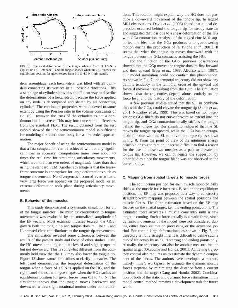
ith
dron assemblage, each hexahedron was filled with 28 cyders connecting its vertices in all possible directions. Tassemblage of cylinders provides an efficient way to descthe deformations of a hexahedron, because the force apon any node is decomposed and shared by all conneccylinders. The continuum properties were achieved to soextent by using the Poisson ratio in the volume constraintEq. ~6!. However, the truss of the cylinders is not a cotinuum but is discrete. This may introduce some differenfrom the standard FEM. The result obtained from the tcuboid showed that the semicontinuum model is sufficifor modeling the continuum body for a first-order appromation.
The major benefit of using the semicontinuum modethat a fast computation can be achieved without any signcant loss in accuracy. Computation times were abouttimes the real time for simulating articulatory movemenwhich are more than two orders of magnitude faster thanusing the standard FEM. Another advantage is that the truframe structure is appropriate for large deformations suchtongue movements. No divergences occurred even whvery large force was applied on the proposed model orextreme deformation took place during articulatory movments.
B. Behavior of the muscles
This study demonstrated a systematic simulation forof the tongue muscles. The muscles’ contribution to tongmovements was evaluated by the normalized amplitudethe EP vectors. Most extrinsic muscles~except the GGa!govern both the tongue tip and tongue dorsum. The SLIL showed clear contributions to the tongue tip movemen
The simulation revealed some differences betweenresults of the present study and those of other studies. Fthe HG moves the tongue tip backward and slightly upwbut not downward. This is somewhat different from the comonly held view that the HG may also lower the tongue tFigure 13 shows some simulations to clarify the causes.left panel demonstrates the temporal deformation oftongue when a force of 1.5 N is applied on the HG, andright panel shows the tongue shapes when the HG reacheequilibrium position for given forces from 0.1 to 4.0 N. Thsimulation shows that the tongue moves backwarddownward with a slight rotational motion under both con
FIG. 13. Temporal deformation of the tongue when a force of 1.5 Napplied on HG~left panel!, and the tongue shapes when the HG reachesequilibrium position for given forces from 0.1 to 4.0 N~right panel!.
J. Acoust. Soc. Am., Vol. 115, No. 2, February 2004 Jianwu Dang and K
n-se
iednge
of-stt
s-0,ats–as
an-
lleof
d.e
st,d-.eeean
d
tions. This rotation might explain why the HG does not prduce a downward movement of the tongue tip. In taggMRI observations, Daviset al. ~1996! found that a local de-pression occurred behind the tongue tip for steady-stateand suggested that it is due to a shear deformation of thewith GGa contraction. Analysis of the tagged cine-MRI suported the idea that the GGa produces a tongue-lowemotion during the production of /a/~Stoneet al., 2001!. Itseems that when the tongue tip moves downward withtongue dorsum the GGa contracts, assisting the HG.
For the function of the GGp, previous observatioshowed that the GGp moves the tongue dorsum first forwand then upward~Baer et al., 1988; Alfonsoet al., 1987!.Our model simulation could not confirm this phenomenoAs shown in Fig. 7, the temporal trajectory did not show adefinite tendency in the temporal order of the upward aforward movements resulting from the GGp. The simulatishowed that the trajectories depend almost entirely onforce level and the history of the deformation.
A few previous studies stated that the SL, in combintion with the GGa, could elevate the tongue tip~Stoneet al.,2001; Napadowet al., 1999!. This was based on two obsevations: GGa fibers do not curve forward or extend intotongue tip, and GGa contraction locally stiffens the tongbehind the tongue tip. Our simulation showed that themoves the tongue tip upward, while the GGa has an antanistic function with the SL to move the tongue tip as showin Fig. 8. From the point of view of the minimum energprinciple or co-contraction, it seems difficult to find a reasfor the use of these two muscles as a pair to elevatetongue tip. However, we cannot negate the suggestionother studies since the tongue blade was not observed incurrent study.
C. Mapping from spatial targets to muscle forces
The equilibrium position for each muscle monotonicashifts as the muscle force increases. Based on the equilibposition, the EP map was proposed as a way to construstraightforward mapping between the spatial positionsmuscle forces. The force estimation based on the EP mfocuses on the spatial target, i.e., the ending point, alone.estimated force activates a muscle constantly until a ntarget is coming. Such a force actually is a static force, sidynamic movements of the model were not considered ding either force estimation processing or the activationriod. For certain large deformations, as shown in Fig. 7,trajectory is not a straight line. It is difficult to define suchcurved trajectory by using its starting and ending points onActually, the trajectory can also be another measure forspatial target~Okadome and Honda, 2001!. Achieving trajec-tory control also requires us to estimate the dynamic comnent of the forces. The authors have developed a metnamelymuscle workspace, to estimate the dynamic musclforces stepwise by minimizing the distance from a currposition and the target~Dang and Honda, 2002!. Combina-tion of both of the static and dynamic force estimations inmodel control method remains a development task for futwork.
se
867iyoushi Honda: Construction and control of articulatory model

gintwth
ilenti
roera
siv
ths,ouha
thbseando
oeenka
bltivst
n.
nitr
en
e
f1
c--
-e
nd-
d
olu-n--leatee
-squi-d.eld
dyter-
ries.
dis-ere-
di-
m-cor--
brick
ased
To simulate co-contractions between agonist and antanist muscles, we designed several three-muscle combtions, consisting of one independent muscle and a pair ofmuscles. The simulation showed that the two muscles ofmuscle pair worked in synergy for one control point whfunctioning as an antagonist muscle pair for the other oThis function can be used to keep the stability of a kinemasystem when a part of the system is manipulated. This perty can be used on the model to achieve multiple targsimultaneously, based on a strategy that accurately guatees the crucial target and optimally reaches the indecitargets.
A method was proposed in this study to estimatemuscle patterns for a given target based on the EP mapwhich all possible force combinations are searchedthrough the EP maps, and then one optimal force set is csen to accurately guarantee the primary feature and optimreach the indecisive features. Model simulation showedthis method is an efficient way to achieve multiple targetsusing the co-contraction mechanism. However, our propomethod may be far different from that used by the humbrain, which is still too complicated for humans to learn ause to optimize muscle activation patterns. Therefore, a mefficient method is still desired.
ACKNOWLEDGMENTS
A part of this study was finished when the first authwas working for the Institut de la Communication Parl~ICP! Grenoble, France. The authors would like to thaPascal Perrier for general discussions as well as thank MTiede, Donna Erickson, and Pierre Badin for their valuacomments. The authors deeply appreciate their instruccomments of Anders Lo¨fqvist and two anonymous reviewerof this paper. This research has been supported in part byTelecommunications Advancement Organization of Japa
APPENDIX: ANALYSIS OF DISPLACEMENT-BASEDFINITE ELEMENT METHOD
The present study adopts a displacement-based fielement method as the basis of the modeling, which isferred to as an extended finite element method~X-FEM!. Theprincipal advantages of X-FEM are that the finite-elemframework~sparsity and symmetry of the stiffness matrix! isretained and that a single-field variational principle is us~Zienkiewicz and Taylor, 1989; Belytschkoet al., 2002!.
To apply the X-FEM to our modeling, the equilibrium oa general 3D body is first considered, as shown in Fig.The body is located in the fixed coordinate systemX, Y, Z.The body surface area is supported on the areaSu with pre-scribed displacementsUSu and is subjected to surface tration fSf on the surface areaSf . In addition, the body is subjected to the externally applied body forcefB andconcentrated loadsRi ~where i denotes the point of load application!. The displacements of the body from the unloadconfiguration are measured in the equation
P~X,Y,Z!5@U,V,W#T, ~A1!
868 J. Acoust. Soc. Am., Vol. 115, No. 2, February 2004 Jianwu Dan
o-a-oe
e.cp-tsn-e
eint
o-llyatyd
n
re
r
rkee
he
e-e-
t
d
4.
d
and P5PSu on the surface area Su. The strains correspoing to P are
«5@«XX«YY«ZZ«XY«YZ«ZX#, ~A2!
where «XX5]P/]X, «YY5]P/]Y, «ZZ5]P/]Z, «XY
5]P/]X1]P/]Y, «YZ5]P/]Y1]P/]Z, «ZX5]P/]Z1]P/]X. The stresses corresponding to« are
t5@tXXtYYtZZtXYtYZtZX#, ~A3!
wheret5C«1t I . C is the stress–strain material matrix anthe vectort I denotes given initial stresses.
The basis of the displacement-based finite-element stion is the principle of virtual displacements, i.e., the priciple of virtual work. This principle states that the equilibrium of the body in Fig. 14 requires that for any compatibsmall virtual displacements imposed on the body in its stof equilibrium, the total internal virtual work is equal to thtotal external virtual work
EV«Tt dV5E
VPTf B dV1E
sf
PsfTf sfdS1(i
PiTRi ,
~A4!
whereP is the virtual displacement and« is the correspond-ing virtual strain. When the principle of virtual displacements is satisfied for all virtual displacements with stresset,all three fundamental requirements of the mechanics, elibrium, compatibility, and the stress–strain law are fulfilleStressest are obtained from a continuous displacement fiP that satisfies the displacement boundary conditions onSu .
In the finite-element analysis, we approximate the boin Fig. 14 as an assemblage of discrete finite elements inconnected at the nodal points on the element boundaDisplacementp measured in a local coordinate systemx,y,zwithin each element is assumed to be a function of theplacement at all nodal points bounded on the element. Thfore, for elementm we have
p~m!~x,y,z!5H ~m!~x,y,z!X~m!, ~A5!
whereH (m) is the displacement interpolation matrix andX(m)
is a vector of global displacement components in threemensions for all nodal points.
Figure 14 shows a typical finite element of the asseblage. This element has eight nodal points, one at eachner, which can be thought of as a ‘‘brick’’ element. The complete body is represented as an assemblage of such
FIG. 14. General three-dimensional description of the displacement-bfinite-element method.
g and Kiyoushi Honda: Construction and control of articulatory model
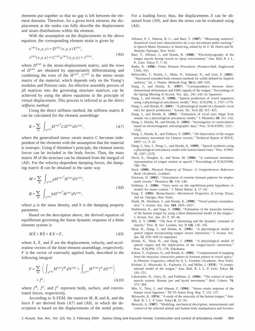
eise
ov
wsnd
g’ssbo
ertiaaop
nit
elveth
n
in
ing
g,’’.
licit
-s of
s70.
21–
E,
hS-
96,
nce
-
e
ue,’’
of
oc.
n,’’
ce,’’
e
.
ndmo-
elements put together so that no gap is left between thement domains. Therefore, for a given brick element, the dplacement at the nodes can fully describe the displacemand strain distributions within the element.
With the assumption on the displacements in the abequation, the corresponding element strain is given by
«~m!~x,y,z!5D ~m!~x,y,z!X~m!,~A6!
t~m!~x,y,z!5C~m!«~m!~x,y,z!1t I ~m!,
whereD (m) is the strain-displacement matrix, and the roof D (m) are obtained by appropriately differentiating acombining the rows of theH (m). C(m) is the stress–strainmatrix of the material, which depends only on the Younmodulus and Poisson ratio. An effective assembly procesall matrices into the governing structure matrices canachieved by using the above equations in the principlevirtual displacement. This process is referred to asthe directstiffness method.
Using the direct stiffness method, the stiffness matrixKcan be calculated for the element assemblage
K5(m
EV~m!
D ~m!TCD~m!dV~m!, ~A7!
where the generalized stress–strain matrixC becomes inde-pendent of the elements with the assumption that the matis isotropic. Using d’Alembert’s principle, the element inerforces can be included in the body forces. Thus, the mmatrix M of the structure can be obtained from the integral~A8!. For the velocity-dependent damping forces, the daming matrix B can be obtained in the same way
M5(m
EV~m!
rH ~m!TH ~m!dV~m!,
~A8!
B5(m
EV~m!
bH~m!TH ~m!dV~m!,
wherer is the mass density, andb is the damping propertyparameter.
Based on the description above, the derived equatioequilibrium governing the linear dynamic response of a finelement system is
MX1BX1KX5F, ~A9!
whereX, X, andX are the displacement, velocity, and acceration vectors of the finite element assemblage, respectiF is the vector of externally applied loads, described infollowing integral:
F5(m
S EV~m!
H ~m! f B dV~m!1ES~m!
HS~m! f S dS~m!D1 f L, ~A10!
where f B, f S, and f L represent body, surface, and concetrated forces, respectively.
According to X-FEM, the matricesM, B, andK, and theforce F are derived from~A7! and ~A8!, in which the de-scription is based on the displacements of the nodal po
J. Acoust. Soc. Am., Vol. 115, No. 2, February 2004 Jianwu Dang and K
le--nt
e
ofef
ial
ssf-
ofe
-ly.e
-
ts.
For a loading force, thus, the displacementsX can be ob-tained from~A9!, and then the stress can be evaluated us~A6!.
Alfonso, P. J., Watson, B. C., and Baer, T.~1987!. ‘‘Measuring stutterers’dynamical vocal tract characteristics by x-ray microbeam pellet trackinin Speech Motor Dynamics in Stuttering, edited by H. F. M. Peters and WHulstijn ~Springer, New York!.
Baer, T., Alfonso, J., and Honda, K.~1988!. ‘‘Electromyography of thetongue muscle during vowels in /]pvp/ environment,’’ Ann. Bull. R. I. L.P., Univ. Tokyo7, 7–18.
Bathe, K. ~1996!. Finite Element Procedures~Prentice-Hall, EnglewoodCliffs, NJ!.
Belytschko, T., Parimi, C., Moe¨s, N., Sukumar, N., and Usui, S.~2002!.‘‘Structured extended finite element methods for solids defined by impsurfaces,’’ Int. J. Numer. Methods Eng.56~4!, 609–635.
Dang, J., and Honda, K.~1997!. ‘‘Correspondence between threedimensional deformation and EMG signals of the tongue,’’ Proceedingthe Spring Meeting of Acoust. Soc. Jpn., 241–242~in Japanese!.
Dang, J., and Honda, K.~1998!. ‘‘Speech production of vowel sequenceusing a physiological articulatory model,’’ Proc. ICSLP98, 5, 1767–17
Dang, J., and Honda, K.~2001!. ‘‘A physiological model of a dynamic vocaltract for speech production,’’ Acoust. Sic. Tech22, 415–425.
Dang, J., and Honda, K.~2002!. ‘‘Estimation of vocal tract shape fromsounds via a physiological articulatory model,’’ J. Phonetics30, 511–532.
Dang, J., Honda, M., and Honda, K.~2002!. ‘‘Investigation of coarticulationbased on electromagnetic articulographic data,’’ Proc. ICSLP2002, 151524.
Dang, J., Honda, K., and Tohkura, Y.~1997!. ‘‘3D observation of the tonguearticulatory movement for Chinese vowels,’’ Technical Report of IEICSP97–11, 9–16.
Dang, J., Sun, J., Deng, L., and Honda, K.~1999!. ‘‘Speech synthesis usinga physiological articulatory model with feature-based rules,’’ Proc. ICP99, 2267–2270.
Davis, E., Douglas, A., and Stone, M.~1996!. ‘‘A continuum mechanicsrepresentation of tongue motion in speech,’’ Proceedings of ICSLP19788–792.
Duck ~1990!. Physical Property of Tissues: A Comprehensive RefereBook ~Academic, London!.
Erickson, D.~2002!. ‘‘Articulation of extreme formant patterns for emphasized vowels,’’ Phonetica59, 134–149.
Feldman, A.~1986!. ‘‘Once more on the equilibrium-point hypothesis~lmodel! for motor control,’’ J. Motor Behav.1, 17–54.
Fung, Y. ~1993!. Biomechanics—Mechanical Properties of Living Tissu,2nd ed.~Spriger, New York!.
Hashi, M., Westbury, J., and Honda, K.~1998!. ‘‘Vowel posture normaliza-tion,’’ J. Acoust. Soc. Am.104, 2426–2437.
Hashimoto, K., and Suga, S.~1986!. ‘‘Estimation of the muscular tensionsof the human tongue by using a three-dimensional model of the tongJ. Acoust. Soc. Jpn.~E! 7, 39–46.
Hill, A. V. ~1938!. ‘‘The heat of shortening and the dynamic constantsmuscle,’’ Proc. R. Soc. London, Ser. B126, 136–195.
Hirai, H., Dang, J., and Honda, K.~1995!. ‘‘A physiological model ofspeech organs incorporating tongue–larynx interaction,’’ J. Acoust. SJpn.52, 918–928~in Japanese!.
Honda, K., Hirai, H., and Dang, J.~1994!. ‘‘A physiological model ofspeech organs and the implications of the tongue-larynx interactioProc. ICSLP94, 175–178, Yokohama.
Kakita, Y., Fujimura, O., and Honda, K.~1985!. ‘‘Computational of mappingfrom the muscular contraction pattern to formant pattern in vowel spain Phonetic Linguistics, edited by A. L. Fromkin~Academic, New York!.
Kiritani, S., Miyawaki, K., Fujimura, O., and Miller, J.~1976!. ‘‘A compu-tational model of the tongue,’’ Ann. Bull. R. I. L. P. Univ. Tokyo10,243–251.
Laboissiere, R., Ostry, D., and Feldman, A.~1996!. ‘‘The control of multi-muscle system: Human jaw and hyoid movement,’’ Biol. Cybern.74,373–384.
Min, Y., Titze, I., and Alipour, F.~1994!. ‘‘Stress–strain response of thhuman vocal ligament,’’ NCVS Status Prog. Rep.7, 131–137.
Miyawaki, K. ~1974!. ‘‘A study of the muscular of the human tongue,’’ AnnBull. R. I. L. P. Univ. Tokyo8, 23–50.
Morecki, A. ~1987!. ‘‘Modeling, mechanical description, measurements acontrol of the selected animal and human body manipulation and loco
869iyoushi Honda: Construction and control of articulatory model

n,
ic
. I
sos
oc.
e,
s-.
-m.
-stry
ap-g.
tion movement,’’ inBiomechanics of Engineering—Modeling, SimulatioControl, edited by A. Morecki~Springer, New York!, pp. 1–28.
Napadow, V. J., Chen, Q., Wedeen, V. J., and Gilbert, R. J.~1999!. ‘‘Intra-mural mechanics of the human tongue in association with physiologdeformations,’’ J. Biomech.32, 1–12.
Niimi, S., Kumada, M., and Niitsu, M.~1994!. ‘‘Functions of tongue-relatedmuscles during production of the five Japanese vowels,’’ Ann. Bull. RL. P. Univ. Tokyo28, 33–40.
Oka, S.~1974!. Rheology–Biorheology~Shokabo, Tokyo, 1974!, pp. 445–456.
Okadome, T., and Honda, M.~2001!. ‘‘Generation of articulatory move-ments by using a kinematic triphone model,’’ J. Acoust. Soc. Am.109,453–463.
Payan, Y., and Perrier, P.~1997!. ‘‘Synthesis of V–V sequences with a 2Dbiomechanical tongue shape in vowel production,’’ Speech Commun.22,185–206.
Perkell, J.~1974!. ‘‘A physiological-oriented model of tongue activity inspeech production,’’ Ph.D. thesis, MIT.
Perkell, J., Cohen, M., Svirsky, M., Matthies, M., Garabieta, I., and JackM. ~1992!. ‘‘Electromagnetic midsagittal articulometer systems for tranducing speech articulatory movements,’’ J. Acoust. Soc. Am.92, 3078–3096.
Sanguineti, V., Laboissie`re, J., and Payan, Y.~1997!. ‘‘A control model ofhuman tongue movements in speech,’’ Biol. Cybern.77, 11–22.
870 J. Acoust. Soc. Am., Vol. 115, No. 2, February 2004 Jianwu Dan
al
.
n,-
Sanguineti, V., Laboissie`re, J., and Ostry, D.~1998!. ‘‘A dynamic biome-chanical model for neural control of speech production,’’ J. Acoust. SAm. 103, 1615–1627.
Stevens, K.~2000!. Acoustic Phonetics~The MIT Press, Cambridge, MA!.Stone, M., Davis, E., Douglas, A., Ness Aiver, M., Gullapalli, R., Levin
W., and Lundberg, A.~2001!. ‘‘Modeling motion of the internal tonguefrom tagged cine-MRI images,’’ J. Acoust. Soc. Am.109, 2974–2982.
Takemoto, H.~2001!. ‘‘Morphological analyses of the human tongue muculature for three-dimensional modeling,’’ J. Speech Lang. Hear. Res44,95–107.
Warfel, J.~1993!. The Head, Neck, and Trunk~Led & Febiger, Philadelphiaand London!.
Wilhelms-Tricarico, R.~1995!. ‘‘Physiological modeling of speech production: Methods for modeling soft-tissue articulators,’’ J. Acoust. Soc. A97, 3805–3898.
Yamazaki, K.~1933!. ‘‘The weight of the cranium and mandible with comparison of the dental and bony regions of the mandible,’’ Jpn. J. Denti26, 769–796~in Japanese!.
Zajac, F.~1989!. ‘‘Muscle and tendon: Properties, models, scaling, andplication to biomechanics and motor control,’’ Crit. Rev. Biomech. En17, 359–411.
Zienkiewicz, O., and Taylor, R.~1989!. The Finite Element Method~McGraw-Hill, New York!.
g and Kiyoushi Honda: Construction and control of articulatory model