Embed Size (px)
Citation preview

Page 1/16
JUMO GmbH & Co. KGDelivery address: Mackenrodtstraße 14,
36039 Fulda, GermanyPostal address: 36035 Fulda, GermanyPhone: +49 661 6003-0Fax: +49 661 6003-607E-mail: [email protected]: www.jumo.net
JUMO Instrument Co. Ltd.JUMO HouseTemple Bank, RiverwayHarlow - Essex CM20 2DY, UKPhone: +44 1279 63 55 33Fax: +44 1279 63 52 62E-mail: [email protected]: www.jumo.co.uk
JUMO Process Control, Inc.8 Technology BoulevardCanastota, NY 13032, USAPhone: 315-697-JUMO
1-800-554-JUMOFax: 315-697-5867E-mail: [email protected]: www.jumo.us
Data Sheet 90.1000
2009-07-01/00073412
The thermoelectric effectThe effect responsible for the action of ther-mocouples is the Seebeck effect. If a term-perature difference exists along a wire, this willcause a displacement of electrical charge. Theamount of the charge displacement dependson the electrical characteristics of the chosenmaterial. If two wires of different materials arejoined at one point and then subjected to atemperature, then a voltage difference will begenerated between the open ends of the twowires. This voltage depends on the tempera-ture difference along the two wires. In order tobe able to measure the temperature at thejunction, the temperature at the open end mustbe known. If the temperature of the open endis not known, then it must be extended (by acompensating cable) into the zone of knowntemperature (reference junction, usually refer-red to as the “cold junction”).
Fig. 1: Measuring circuit (schematic)
The temperature of the reference junctionmust be known and constant. If no constantreference junction temperature is available, thereference junction has to be arranged as athermostat, or its temperature has to be deter-mined by means of a second sensor.
Thermocouplesto EN 60 584 and DIN 43 710From the variety of possible metal combina-tions, certain ones have been selected (Tables1 and 2) and their voltage tables and permittedtolerances incorporated in standard specifica-tions (Fig. 2 and Tables 3 and 4).Note that two Fe-Con thermocouples (Type Jand L) and two Cu-Con thermocouples (TypeT and U) have been standardized in both EN60 584 and DIN 43 710.The “old” thermocouples L and U are now be-ing used less frequently than the thermocou-
Reference junction
Termination
Measuring junction
ples J and T to EN 60 584.
The individual thermocouples are not com-patible, because of their differing alloy com-positions. If a Fe-Con thermocouple Type L isconnected to an instrument linearized forType J, the difference in the thermal voltagesleads to errors of up to several °C. The sameapplies to thermocouples Type U and T.
The maximum temperature represents thelimit to which a tolerance is specified.The value under “defined to” is the tempera-ture limit to which the thermal voltage is cov-ered by standard specifications.In the thermocouples listed above, the firstlimb is always the positive one. The colorcodes apply both to the thermocouple itselfand to the compensating cables. If the ther-mocouple wires are not color coded, the fol-lowing differences may help to identify them.
Fe-Con: positive limb is magneticCu-Con: positive limb is copper coloredNiCr-Ni: negative limb is magneticPtRh-Pt: negative limb is softer
These distinctions do not apply to the com-pensating cables.The thermocouples are insulated inside thefittings using ceramic materials. PVC, sili-cone, PTFE or glass fiber are used in the ca-bles.
TolerancesEN 60 584 defines three tolerance classes forthermocouples. They normally apply to ther-mowires between 0.25 to 3mm diameter andto the condition as supplied. The standardcannot cover any possible subsequent age-ing, since this largely depends on the condi-tions of use. The temperature limits specifiedfor the tolerance classes are not necessarilythe recommended operating temperature lim-its (see Tables 3 and 4).The larger value applies in each case.
Fig. 2: Tolerances
Temperature/°C
Tole
ranc
e/°
C
Type T
Type B, R, S
Type E, J, K, N
Construction and application of thermocouples
Table 1: Thermocouples to EN 60 584
* Continuous temperature in pure airTable 2: Thermocouples to DIN 43 710
Thermocouple Maximumtemperature
Definedup to
Positivelimb
Negativelimb
Fe-Con JCu-Con TNiCr-Ni KNiCr-Con ENiCrSi-NiSi NPt10Rh-Pt SPt13Rh-Pt RPt30Rh-Pt6Rh B
750°C350°C
1200°C900°C
1200°C1600°C1600°C1700°C
1200°C400°C
1370°C1000°C1300°C1540°C1760°C1820°C
blackbrowngreenvioletmauveorangeorangeno data
whitewhitewhitewhitewhitewhitewhitewhite
Thermocouple Maximumtemperature
Definedup to
Positivelimb
Negativelimb
Fe-Con LCu-Con U
700°C400°C
900°C600°C
redred
bluebrown
2009-07-01/00073412
Page 2/16Data Sheet 90.1000
JUMO GmbH & Co. KGDelivery address: Mackenrodtstraße 14,
36039 Fulda, GermanyPostal address: 36035 Fulda, GermanyPhone: +49 661 6003-0Fax: +49 661 6003-607E-mail: [email protected]: www.jumo.net
JUMO Instrument Co. Ltd.JUMO HouseTemple Bank, RiverwayHarlow - Essex CM20 2DY, UKPhone: +44 1279 63 55 33Fax: +44 1279 63 52 62E-mail: [email protected]: www.jumo.co.uk
JUMO Process Control, Inc.8 Technology BoulevardCanastota, NY 13032, USAPhone: 315-697-JUMO
1-800-554-JUMOFax: 315-697-5867E-mail: [email protected]: www.jumo.us
Table 3: Tolerances to EN 60 584
Table 4: Tolerances to DIN 43 710 (1977)
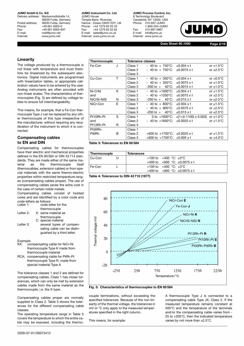
Fig. 3: Characteristics of thermocouples to EN 60 584
Thermocouple Tolerance classesFe-Con J Class 1
Class 2Class 3
- 40 to + 750°C:- 40 to + 750°C:
±0.004 x t±0.0075 x t
or ±1.5°Cor ±2.5°C
Cu-Con T Class 1Class 2Class 3
- 40 to + 350°C:- 40 to + 350°C:-200 to + 40°C:
±0.004 x t±0.0075 x t±0.0015 x t
or ±0.5°Cor ±1.0°Cor ±1.0°C
Ni-CrNi KandNiCrSi-NiSi N
Class 1Class 2Class 3
- 40 to +1000°C:- 40 to +1200°C:-200 to + 40°C:
±0.004 x t±0.0075 x t±0.015 x t
or ±1.5°Cor ±2.5°Cor ±2.5°C
NiCr-Con E Class 1Class 2Class 3
- 40 to + 800°C:- 40 to + 900°C:-200 to + 40°C:
±0.004 x t±0.0075 x t±0.015 x t
or ±1.5°Cor ±2.5°Cor ±2.5°C
Pt10Rh-Pt SandPt13Rh-Pt R
Class 1Class 2Class 3
0 to +1600°C:- 40 to +1600°C:
±[1+(t-1100) x 0.003]±0.0025 x t
or ±1.0°Cor ±1.5°C
Pt30Rh-Pt6Rh B
Class 1Class 2Class 3
+600 to +1700°C:+600 to +1700°C:
±0.0025 x t±0.005 x t
or ±1.5°Cor ±4.0°C
Thermocouple TolerancesCu-Con U +100 to +400 °C: ±3°C
+400 to +600 °C: ±0.0075 x tFe-Con L +100 to +400 °C: ±3°C
+400 to +900 °C: ±0.0075 x t
Temperature/°C
Ther
mal
vol
tage
/mV
NiCr-Con E
Fe-Con J
NiCr-Ni K
NiCrSi-NiSi N
Pt13Rh-Pt R
Pt10Rh-Pt S
Pt30Rh-Pt6Rh B
LinearityThe voltage produced by a thermocouple isnot linear with temperature and must there-fore be liniearized by the subsequent elec-tronics. Digital instruments are programmedwith linearization tables, or appropriate cali-bration values have to be entered by the user.Analog instruments are often provided withnon-linear scales. The characteristics of ther-mocouples (Fig. 3) are defined by voltage ta-bles to ensure full interchangeability.
This means, for example, that a Fe-Con ther-mocouple Type J can be replaced by any oth-er thermocouple of this type irrespective ofthe manufacturer, without requiring any reca-libration of the instrument to which it is con-nected.
Compensating cablesto EN and DINCompensating cables for thermocoupleshave their electric and mechanical propertiesdefined in the EN 60 584 or DIN 43 714 stan-dards. They are made either of the same ma-terial as the thermocouple itself(thermocables, extension cables) or from spe-cial materials with the same thermo-electricproperties within restricted temperature rang-es (compensating cables proper). The use ofcompensating cables saves the extra cost inthe case of certain noble metals.Compensating cables consist of twistedcores and are identified by a color code andcode letters as follows:
Example:
The tolerance classes 1 and 2 are defined forcompensating cables. Class 1 has closer tol-erances, which can only be met by extensioncables made from the same material as thethermocouple, i.e. the X-type.
Compensating cables proper are normallysupplied to Class 2. Table 5 shows the toler-ances for the different compensating cableclasses.The operating temperature range in Table 5covers the temperature to which the entire ca-ble may be exposed, including the thermo-
Letter 1: code letter for the thermocouple
Letter 2: X: same material as thermocouple
C: special materialLetter 3: several types of compen-
sating cable can be distin-guished by a third letter.
KX: compensating cable for NiCr-Ni thermocouple Type K made from thermocouple material
RCA: compensating cable for PtRh-Pt thermocouple Type R, made from special material Type A
couple terminations, without exceeding thespecified tolerances. Because of the non-lin-earity of the thermal voltage, the tolerances inmV or °C only apply to the measured temper-atures specified in the right column.
This means, for example:
A thermocouple Type J is connected to acompensating cable Type JX, Class 2. If themeasured temperature remains constant at500°C and the temperature of the terminalsand/or the compensating cable varies from -25 to +200°C, then the indicated temperaturevaries by not more than ±2.5°C.
2009-07-01/00073412
Page 3/16Data Sheet 90.1000
JUMO GmbH & Co. KGDelivery address: Mackenrodtstraße 14,
36039 Fulda, GermanyPostal address: 36035 Fulda, GermanyPhone: +49 661 6003-0Fax: +49 661 6003-607E-mail: [email protected]: www.jumo.net
JUMO Instrument Co. Ltd.JUMO HouseTemple Bank, RiverwayHarlow - Essex CM20 2DY, UKPhone: +44 1279 63 55 33Fax: +44 1279 63 52 62E-mail: [email protected]: www.jumo.co.uk
JUMO Process Control, Inc.8 Technology BoulevardCanastota, NY 13032, USAPhone: 315-697-JUMO
1-800-554-JUMOFax: 315-697-5867E-mail: [email protected]: www.jumo.us
Color coding ofcompensating cablesThe color coding of compensating cables islaid down in EN 60 584 and DIN 43 713 (1990).For thermocouples to EN 60 584 (Table 6) thismeans:The positive limb has the same color as thesheath, the negative limb is white. The “old”thermocouples Type L and U to DIN 43 713(Table 7) are coded differently.
There are no details for the Pt30Rh-Pt6Rhthermocouple Type B. Ordinary copper con-necting cables (plain copper) can be used ascompensating cables in this case.
According to DIN 43 714, the cable cores aretwisted together for electromagnetic screen-ing. Additional screening by foil or braidingcan be provided. The insulation resistancebetween the cores and between cores andscreening must not be less than 107Ω x m-1 atthe maximum temperature;the breakdown voltage exceeds 500 VAC.
In addition to these color codes for compen-sating cables, there are also those accordingto DIN 43 714, 1979 (Table 8). They differ incertain respects from the ones mentionedabove.
Where there are no color codes, it is not pos-sible to identify cables by magnetism, color orhardness. Compensating cables Type KCAand KCB differ from the thermocable KX andthe thermocouple Type K by having a mag-netic positive limb.
Table 5: Tolerances for thermocables and compensating cables
Table 6: Color coding for thermocouples to EN 60 584
Table 7: Color coding for thermocouples to DIN 43 713
Table 8: Color coding for thermocouples to DIN 43 714 (1979)
Thermo-couple and wiretype
Tolerance classes1 2
Operatingtemperaturerange[°C]
Measuringtemperature
[°C]JXTXEXKXNXKCAKCBNCRCARCBSCASCB
± 85µV/±1.5°C± 30µV/±0.5°C± 120µV/±1.5°C± 60µV/±1.5°C± 60µV/±1.5°C-------
± 140µV/±2.5°C± 60µV/±1.0°C± 200µV/±2.5°C± 100µV/±2.5°C± 100µV/±2.5°C± 100µV/±2.5°C± 100µV/±2.5°C± 100µV/±2.5°C± 30µV/±2.5°C± 60µV/±5.0°C± 30µV/±2.5°C± 60µV/±5.0°C
-25 to +200-25 to +100-25 to +200-25 to +200-25 to +200
0 to +1500 to +1000 to +1500 to +1000 to +2000 to +1000 to +200
500300500900900900900900
1000100010001000
Thermocouple Type Sheath Positive limb Negative limbCu-ConFe-ConNiCr-NiNiCrSi-NiSiNiCr-ConPt10Rh-PtPt13Rh-Pt
TJKNESR
brownblackgreenmauvevioletorangeorange
brownblackgreenmauvevioletorangeorange
whitewhitewhitewhitewhitewhitewhite
Thermocouple Type Sheath Positive limb Negative limbFe-ConCu-Con
LU
bluebrown
redred
bluebrown
Thermocouple Type Sheath Positive limb Negative limbNiCr-NiPt10Rh-PtPt13Rh-Pt
KSR
greenwhitewhite
redredred
greenwhitewhite
2009-07-01/00073412
Page 4/16Data Sheet 90.1000
JUMO GmbH & Co. KGDelivery address: Mackenrodtstraße 14,
36039 Fulda, GermanyPostal address: 36035 Fulda, GermanyPhone: +49 661 6003-0Fax: +49 661 6003-607E-mail: [email protected]: www.jumo.net
JUMO Instrument Co. Ltd.JUMO HouseTemple Bank, RiverwayHarlow - Essex CM20 2DY, UKPhone: +44 1279 63 55 33Fax: +44 1279 63 52 62E-mail: [email protected]: www.jumo.co.uk
JUMO Process Control, Inc.8 Technology BoulevardCanastota, NY 13032, USAPhone: 315-697-JUMO
1-800-554-JUMOFax: 315-697-5867E-mail: [email protected]: www.jumo.us
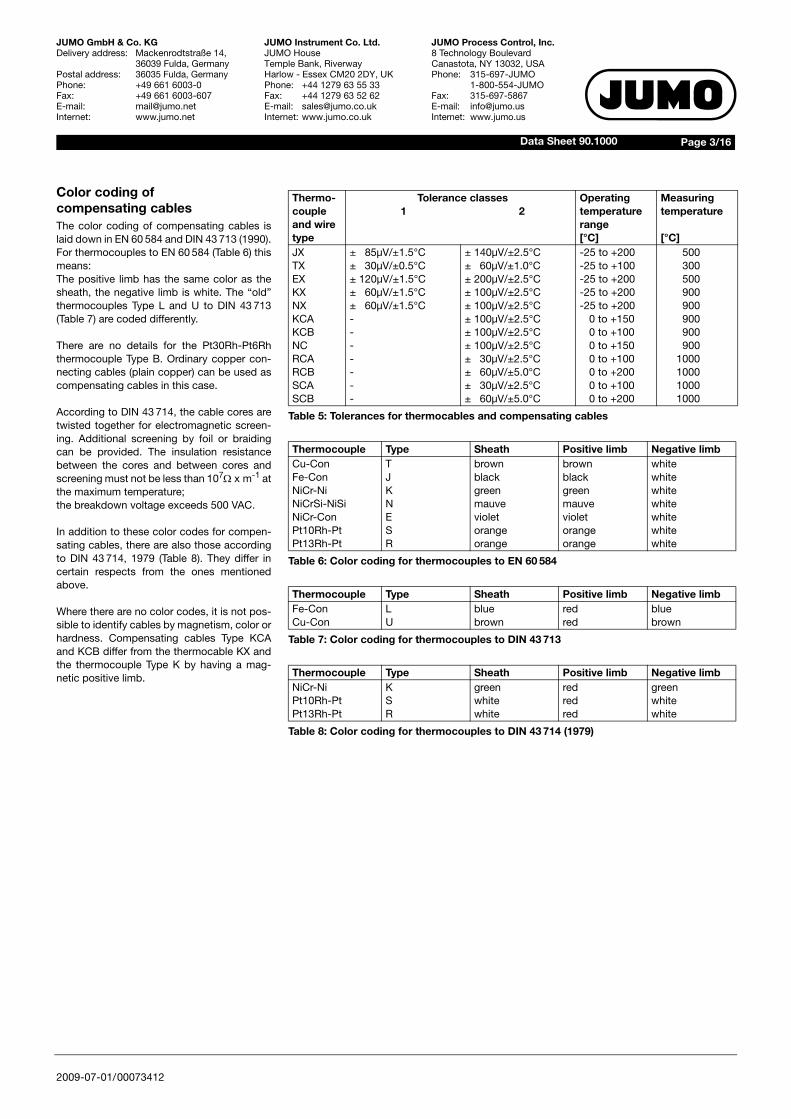
Construction of thermocouplesApart from the virtually unlimited number ofspecial models, there are also those whosecomponents are completely defined by stan-dard specifications.
Thermocouples with terminal headThese thermocouples are of modular con-struction, consisting of the thermocoupleproper, insert tube, terminal plate, protectiontube and the terminal head. A flange or ascrew fitting can be provided for mounting inposition.
Fig. 4: Construction of a thermocouple
The measuring insert is a completely fabri-cated unit consisting of thermocouple sensorand terminal plate, with the thermocouplecontained in an insert tube of 6 or 8 mm di-ameter made from bronze SnBz6 to DIN17 681 (up to 300°C) or nickel. It is insertedinto the actual protection tube, which is oftenmade from stainless steel. The tip of the inserttube is in full contact with the inside of theprotection tube end plate in order to ensuregood heat transfer. The fixing screws of theinsert are backed by springs, to maintaingood contact even with differential expansionbetween insert tube and protection tube. Thisarrangement ensures that the insert can bereadily replaced.The thermometers are available in single andtwin versions. Their dimensions are laid downin DIN 43 735. If no measuring insert is used,the thermocouple is mounted directly in theprotection tube using ceramic insulation.The choice of the protection tube material de-pends on the thermal, chemical and mechan-ical conditions on site.
Metal protection tubes in high-temperaturesteel, e.g. Material Ref. 1.4749, are used up to1150°C. The corrosion resistance of the pro-tection tube materials is described in DIN
Terminal head
Terminal plate
Screw fitting
Thermocouple wires
Insert tube
Protection tube
Thermocouple
43 720.These details are provided for general infor-mation only, and the user remains responsiblefor fully evaluating the protection tube materi-al for its suitability to the operating conditionson site. The indicated temperature refers tothe use without mechanical loads and (unlessotherwise specified) in clean air.
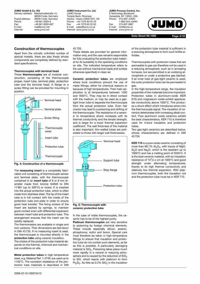
Ceramic protection tubes are employedwhere local conditions prevent the use ofmetal fittings, either for chemical reasons orbecause of high temperatures. Their main ap-plication is at temperatures between 1000and 1650°C. They may be in direct contactwith the medium, or may be used as a gas-tight inner tube to separate the thermocouplefrom the actual protection tube. Even haircracks may lead to a poisoning and drifting ofthe thermocouple. The resistance of a ceram-ic to temperature shock increases with itsthermal conductivity and the tensile strength,and is larger for a lower thermal expansioncoefficient. The wall thickness of the materialis also important; thin-walled tubes are pref-erable to those with larger wall thicknesses.
Fig. 5: Thermocouple withceramic protection tube
In the case of noble thermocouples, the ce-ramic has to be of the highest purity.Platinum thermocouples are very sensitiveto poisoning by foreign chemical elements.These include especially silicon, arsenic,phosphorus, sulfur and boron. Special caremust therefore be taken in high-temperaturefittings to ensure that insulation and protec-tion tube do not contain such elements, as faras this is possible. A particularly damagingmaterial is SiO2. Poisoning takes place muchmore rapidly in a neutral or reducing atmo-sphere and is caused by the reduction of SiO2to SiO, which reacts with platinum to formPt5Si2. As little as 0.2% SiO2 in the insulation
Terminal head
Support tube
Stop flange
Protection tube
of the protection tube material is sufficient ina reducing atmosphere to form such brittle si-licides.
Thermocouples with protection tubes that arepermeable to gas can therefore not be used ina reducing atmosphere, such as in annealingfurnaces, but are permitted in an oxidizing at-mosphere or under a protective gas blanket.If an inner tube of gas-tight ceramic is used,the outer protection tube can be permeable togas.In the high-temperature range, the insulationproperties of the materials become important.Protection tubes in aluminium-oxide (KER610) and magnesium oxide exhibit apprecia-ble conductivity above 1000°C. This produc-es a shunt effect which introduces errors intothe thermocouple signal. The insulation of ce-ramics deteriorates with increasing alkali con-tent. Pure aluminium oxide ceramics exhibitthe best characteristics. KER 710 is thereforeused for 4-bore insulators and protectiontubes.Two gas-tight ceramics are described below,whose characteristics are defined in DIN43 724:
KER 710 is a pure oxide ceramic consisting ofmore than 99.7% AI2O3, with traces of MgO,Si2O and Na2O, which is fire resistant up to1900°C and has a melting point of 2050°C. Itis the best ceramic material, with an insulationresistance of 107Ω x cm at 1000°C and goodstrength under alternating temperatures,thanks to its high thermal conductivity andrelatively low thermal expansion. With plati-num thermocouples, both the insulation rodand the protection tube must be in KER 710.

2009-07-01/00073412
Page 5/16Data Sheet 90.1000
JUMO GmbH & Co. KGDelivery address: Mackenrodtstraße 14,
36039 Fulda, GermanyPostal address: 36035 Fulda, GermanyPhone: +49 661 6003-0Fax: +49 661 6003-607E-mail: [email protected]: www.jumo.net
JUMO Instrument Co. Ltd.JUMO HouseTemple Bank, RiverwayHarlow - Essex CM20 2DY, UKPhone: +44 1279 63 55 33Fax: +44 1279 63 52 62E-mail: [email protected]: www.jumo.co.uk
JUMO Process Control, Inc.8 Technology BoulevardCanastota, NY 13032, USAPhone: 315-697-JUMO
1-800-554-JUMOFax: 315-697-5867E-mail: [email protected]: www.jumo.us
The material KER 610 has a higher alkali con-tent (60% AI2O3, 37% SiO2, 3% alkali) and,therefore, a low insulation resistance of about104Ω x cm at 1000°C. Because of the high sil-icon dioxide content, it cannot be used in a re-ducing atmosphere. Compared with KER 710,it has only one-ninth the thermal conductivity;its mechanical stability is good.The advantage of KER 610 is its price, whichis only about one-fifth that of KER 710.
For the terminal heads, DIN 43 729 definesthe two forms A and B, which differ in size andalso slightly in style.
Fig. 6: Terminal head to DIN 43 729,Form B
The material used is aluminium.
Protection is not covered by a standard; it isusually splash-proof to IP54. The nominal di-ameter of the bore to take the protection tubeis as follows:
Form A: 22, 24 or 32 mm.Form B: 15 mm or thread M 24 x 1.5.
Thermocouples to DIN EN 14 597Thermocouples for use with temperature con-trollers or temperature limiters for indirectheating systems must meet the requirementsof DIN EN 14 597 and are subject to addition-al TUV approval.
The thermocouples must withstand tempera-tures that are 15% above the upper tempera-ture limit for at least one hour and have tomeet certain response times in relation to themedium (e.g. air t0.63 = 120sec). The ther-mometers are designed to withstand me-chanical loads caused by external pressureand the flow velocity of the medium at the op-erating temperature.
No modifications to the thermometers arepermitted without obtaining a fresh TUV ap-proval!
Thermocoupleswith compensating cableThermocouples with an attached compensat-ing cable do not have a measuring insert or aterminal head. The thermocouple is directlyconnected to the thermocable or the com-pensating cable and enclosed in the protec-tion tube. Strain relief is provided by crimpingthe protection tube at the entry of the com-pensating cable.The thermocouple is normally insulated; alter-natively, it can be welded to the protectiontube tip for improved thermal contact. Themaximum temperature is determined mainlyby the thermal stability of the cable sheathand insulation. Table 9 shows as examplessome insulation materials and their uppertemperature limit.
Table 9: Temperature limits ofinsulation materials
There are many different thermometer de-signs, and they are often adapted to suit par-ticular customer requirements.Some characteristic data are given below:
- diameter: 0.5 – 6mm- protection tube length: 35 – 150mm- protection tube material: stainless steel,
heat-resistant steel or brass- mounting: fixed or sliding flange,
fixed thread or clamp
Material Max. temperature °C
PVC 80
Silicone 180
PTFE 260
Glass fiber 350
Fig. 7: Construction of a thermocouplewith compensating cable
Thermocoupleswith bayonet fittingAnother version incorporates a bayonet fit-ting. The stainless steel pressure spring (Ma-terial Ref. 1.4310) also acts as a cableprotector and ensures uniform pressure of theprotection tube and sensing tip against thebottom of the bore.
The fitting length can be varied by rotating thebayonet lock. Bayonet fittings and socketsare available in 12, 15 and 16 mm diameters.
Fig. 8: Thermocouplewith bayonet fitting
Thermocouples with a bayonet fitting arelargely employed for measuring temperaturesin solids, on bearings and moulding tools, e.g.in the plastics industry. Because of the spe-cial shape of the sensing tip, these thermo-
Compensating cable
Screw fitting
Protection tube
Thermocouple
Compensating cable
Pressure spring
Bayonet fitting
Protection tube
2009-07-01/00073412
Page 6/16Data Sheet 90.1000
JUMO GmbH & Co. KGDelivery address: Mackenrodtstraße 14,
36039 Fulda, GermanyPostal address: 36035 Fulda, GermanyPhone: +49 661 6003-0Fax: +49 661 6003-607E-mail: [email protected]: www.jumo.net
JUMO Instrument Co. Ltd.JUMO HouseTemple Bank, RiverwayHarlow - Essex CM20 2DY, UKPhone: +44 1279 63 55 33Fax: +44 1279 63 52 62E-mail: [email protected]: www.jumo.co.uk
JUMO Process Control, Inc.8 Technology BoulevardCanastota, NY 13032, USAPhone: 315-697-JUMO
1-800-554-JUMOFax: 315-697-5867E-mail: [email protected]: www.jumo.us
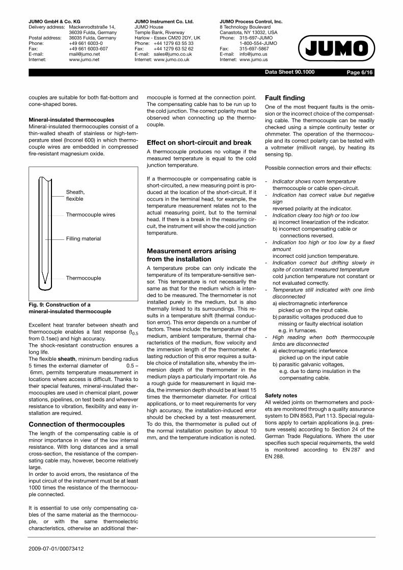
couples are suitable for both flat-bottom andcone-shaped bores.
Mineral-insulated thermocouplesMineral-insulated thermocouples consist of athin-walled sheath of stainless or high-tem-perature steel (Inconel 600) in which thermo-couple wires are embedded in compressedfire-resistant magnesium oxide.
Fig. 9: Construction of amineral-insulated thermocouple
Excellent heat transfer between sheath andthermocouple enables a fast response (t0.5from 0.1sec) and high accuracy.The shock-resistant construction ensures along life.The flexible sheath, minimum bending radius5 times the external diameter of 0.5 –6mm, permits temperature measurement in
locations where access is difficult. Thanks totheir special features, mineral-insulated ther-mocouples are used in chemical plant, powerstations, pipelines, on test beds and whereverresistance to vibration, flexibility and easy in-stallation are required.
Connection of thermocouplesThe length of the compensating cable is ofminor importance in view of the low internalresistance. With long distances and a smallcross-section, the resistance of the compen-sating cable may, however, become relativelylarge.In order to avoid errors, the resistance of theinput circuit of the instrument must be at least1000 times the resistance of the thermocou-ple connected.
It is essential to use only compensating ca-bles of the same material as the thermocou-ple, or with the same thermoelectriccharacteristics, otherwise an additional ther-
Sheath,flexible
Thermocouple wires
Filling material
Thermocouple
mocouple is formed at the connection point.The compensating cable has to be run up tothe cold junction. The correct polarity must beobserved when connecting up the thermo-couple.
Effect on short-circuit and breakA thermocouple produces no voltage if themeasured temperature is equal to the coldjunction temperature.
If a thermocouple or compensating cable isshort-circuited, a new measuring point is pro-duced at the location of the short-circuit. If itoccurs in the terminal head, for example, thetemperature measurement relates not to theactual measuring point, but to the terminalhead. If there is a break in the measuring cir-cuit, the instrument will show the cold junctiontemperature.
Measurement errors arising from the installationA temperature probe can only indicate thetemperature of its temperature-sensitive sen-sor. This temperature is not necessarily thesame as that for the medium which is inten-ded to be measured. The thermometer is notinstalled purely in the medium, but is alsothermally linked to its surroundings. This re-sults in a temperature shift (thermal conduc-tion error). This error depends on a number offactors. These include: the temperature of themedium, ambient temperature, thermal cha-racteristics of the medium, flow velocity andthe immersion length of the thermometer. Alasting reduction of this error requires a suita-ble choice of installation site, whereby the im-mersion depth of the thermometer in themedium plays a particularly important role. Asa rough guide for measurement in liquid me-dia, the immersion depth should be at least 15times the thermometer diameter. For criticalapplications, or to meet requirements for veryhigh accuracy, the installation-induced errorshould be checked by a test measurement.To do this, the thermometer is pulled out ofthe normal installation position by about 10mm, and the temperature indication is noted.
Fault findingOne of the most frequent faults is the omis-sion or the incorrect choice of the compensat-ing cable. The thermocouple can be readilychecked using a simple continuity tester orohmmeter. The operation of the thermocou-ple and its correct polarity can be tested witha voltmeter (millivolt range), by heating itssensing tip.
Possible connection errors and their effects:
- Indicator shows room temperaturethermocouple or cable open-circuit.
- Indication has correct value but negativesignreversed polarity at the indicator.
- Indication cleary too high or too lowa) incorrect linearization of the indicator.b) incorrect compensating cable or connections reversed.
- Indication too high or too low by a fixedamountincorrect cold junction temperature.
- Indication correct but drifting slowly inspite of constant measured temperaturecold junction temperature not constant ornot evaluated correctly.
- Temperature still indicated with one limbdisconnecteda) electromagnetic interference
picked up on the input cable.b) parasitic voltages produced due to
missing or faulty electrical isolatione.g. in furnaces.
- High reading when both thermocouplelimbs are disconnecteda) electromagnetic interference
picked up on the input cableb) parasitic galvanic voltages,
e.g. due to damp insulation in thecompensating cable.
Safety notesAll welded joints on thermometers and pock-ets are monitored through a quality assurancesystem to DIN 8563, Part 113. Special regula-tions apply to certain applications (e.g. pres-sure vessels) according to Section 24 of theGerman Trade Regulations. Where the userspecifies such special requirements, the weldis monitored according to EN 287 andEN 288.

2009-07-01/00073412
Page 7/16Data Sheet 90.1000
JUMO GmbH & Co. KGDelivery address: Mackenrodtstraße 14,
36039 Fulda, GermanyPostal address: 36035 Fulda, GermanyPhone: +49 661 6003-0Fax: +49 661 6003-607E-mail: [email protected]: www.jumo.net
JUMO Instrument Co. Ltd.JUMO HouseTemple Bank, RiverwayHarlow - Essex CM20 2DY, UKPhone: +44 1279 63 55 33Fax: +44 1279 63 52 62E-mail: [email protected]: www.jumo.co.uk
JUMO Process Control, Inc.8 Technology BoulevardCanastota, NY 13032, USAPhone: 315-697-JUMO
1-800-554-JUMOFax: 315-697-5867E-mail: [email protected]: www.jumo.us
Pressure loading for temperature probesThe pressure resistance of protection fittings,such as are used for electric thermometers,depends largely on the different process pa-rameters.These include:- temperature- pressure- flow velocity- vibrationIn addition, physical properties, such as ma-terial, fitting length, diameter and type of pro-cess connection have to be taken intoaccount.
The following diagrams are taken from DIN43 763 and show the load limit for the differentbasic types in relation to the temperature andthe fitting length, as well as the flow velocity,temperature and medium
.
Fig. 10: Pressure loadingfor protection tube Form B
stainless steel 1.4571velocity up to 25m/sec in airvelocity up to 3m/sec in water
Fig. 11: Pressure loadingfor protection tube Form G
stainless steel 1.4571velocity up to 40m/sec in airvelocity up to 4m/sec in water
Satu
rate
d st
eam
Sat
urat
ed s
team
2009-07-01/00073412
Page 8/16Data Sheet 90.1000
JUMO GmbH & Co. KGDelivery address: Mackenrodtstraße 14,
36039 Fulda, GermanyPostal address: 36035 Fulda, GermanyPhone: +49 661 6003-0Fax: +49 661 6003-607E-mail: [email protected]: www.jumo.net
JUMO Instrument Co. Ltd.JUMO HouseTemple Bank, RiverwayHarlow - Essex CM20 2DY, UKPhone: +44 1279 63 55 33Fax: +44 1279 63 52 62E-mail: [email protected]: www.jumo.co.uk
JUMO Process Control, Inc.8 Technology BoulevardCanastota, NY 13032, USAPhone: 315-697-JUMO
1-800-554-JUMOFax: 315-697-5867E-mail: [email protected]: www.jumo.us
As explained in the standard, the values indi-cated are guide values, which have to be indi-vidually examined for the specific application.Slight differences in the measurement condi-tions may suffice to destroy the protectiontube.If, when ordering an electric thermometer, theprotection fitting needs to be checked, theload type and the limit values must be speci-fied.
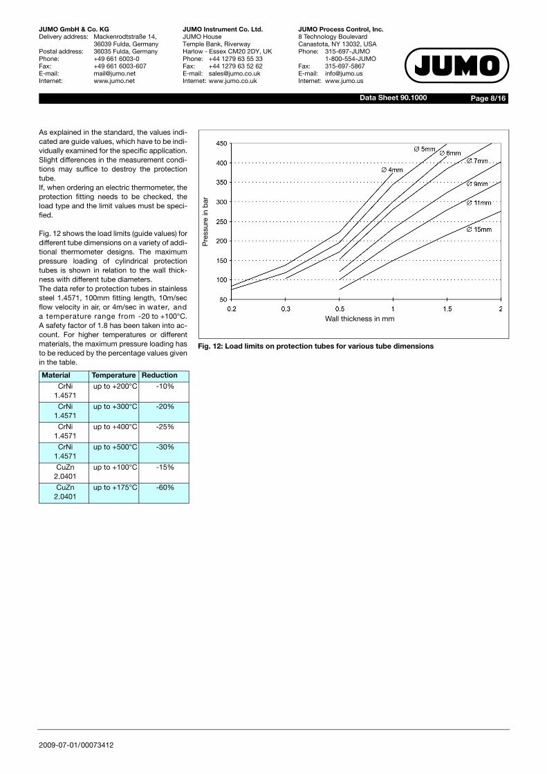
Fig. 12 shows the load limits (guide values) fordifferent tube dimensions on a variety of addi-tional thermometer designs. The maximumpressure loading of cylindrical protectiontubes is shown in relation to the wall thick-ness with different tube diameters.The data refer to protection tubes in stainlesssteel 1.4571, 100mm fitting length, 10m/secflow velocity in air, or 4m/sec in water, anda temperature range from -20 to +100°C.A safety factor of 1.8 has been taken into ac-count. For higher temperatures or differentmaterials, the maximum pressure loading hasto be reduced by the percentage values givenin the table.
Material Temperature Reduction
CrNi1.4571
up to +200°C -10%
CrNi1.4571
up to +300°C -20%
CrNi1.4571
up to +400°C -25%
CrNi1.4571
up to +500°C -30%
CuZn2.0401
up to +100°C -15%
CuZn2.0401
up to +175°C -60%
Wall thickness in mm
Pre
ssur
e in
bar
Fig. 12: Load limits on protection tubes for various tube dimensions
2009-07-01/00073412
Page 9/16Data Sheet 90.1000
JUMO GmbH & Co. KGDelivery address: Mackenrodtstraße 14,
36039 Fulda, GermanyPostal address: 36035 Fulda, GermanyPhone: +49 661 6003-0Fax: +49 661 6003-607E-mail: [email protected]: www.jumo.net
JUMO Instrument Co. Ltd.JUMO HouseTemple Bank, RiverwayHarlow - Essex CM20 2DY, UKPhone: +44 1279 63 55 33Fax: +44 1279 63 52 62E-mail: [email protected]: www.jumo.co.uk
JUMO Process Control, Inc.8 Technology BoulevardCanastota, NY 13032, USAPhone: 315-697-JUMO
1-800-554-JUMOFax: 315-697-5867E-mail: [email protected]: www.jumo.us
Pressure test for thermometerprotection fittingsThe welded protection fittings of JUMO ther-mometers are subjected to a leakage test or apressure test, depending on the constructionof the protection fitting.
Thermometers which are manufactured to DINor to application-specific guidelines (chemicalor petrochemical plant, pressure vessel regu-lation, steam boilers) require different pressuretests according to the specific application.If the thermometers are to be manufactured tosuch standards or guidelines, then the re-quired tests or standards and/or guidelineshave to be specified when ordering.
Scope of testTests can be carried out on each individualprotection fitting and documented in a test re-port or acceptance certificate to EN 10 204 (atextra cost).
Type of testTests can be performed on protection fittingsup to a fitting length of 1050mm with flangeconnection DN25 or screw connection up to 1"thread size.
The following tests can be carried out:
Leakage testA vacuum is produced inside the protectiontube. From the outside, helium is applied to theprotection fitting. If there is a leak in the pro-tection tube, helium will penetrate and will berecognized through analysis. A leakage rate isdetermined by the rise in pressure (leakagerate > 1 x 10⁻⁶ l/bar).
Pressure test IA positive pressure of nitrogen is applied to theprotection tube from the outside. If there is aleak in the fitting, a volume flow will be pro-duced inside the protection tube, which will berecognized.Pressure test IIWater pressure is applied to the protectiontube from the outside. The pressure must re-main constant for a certain length of time. Ifthis is not the case, the protection fitting has aleak.
Qualified welding processesfor the production ofprotection tubes for thermometers
In addition to using perfect materials, it is thejoining technique which ultimately determinesthe mechanical stability and quality of the pro-tection fittings. This is why the welding tech-niques at JUMO comply with the EuropeanStandards EN 287 and EN 288. Manual weld-ing is carried out by qualified welders accord-ing to EN 287. Automatic welding processesare qualified by a WPS (welding instruction) toEN 288.
The following table gives an overview of quali-fied welding processes:
Based on these experiences, our welders canalso join different materials and dimensions.
Laser beam welding is employed for wall thick-nesses of less than 0.6mm, which is monitoredby a laser beam specialist according to guide-line DSV 1187.
On customer request, material test certificatescan be issued at extra cost. Likewise, specialtests and treatments can be carried out, whichare calculated according to the extent of thework, as set out in various application guide-lines. This includes X-ray examinations, cracktest (dye penetration test), thermal treatment,special cleaning processes and markings.
Testtype
Testmedium
Pressurerange
Testdura-tion
Leakagetest
helium vacuum 10sec
Pressuretest I
nitrogen 1 — 50bar 10sec
Pressuretest II
water 50 — 300bar 10sec
Table 10: Qualified welding processes
WIG welding
Material manual automatic
W11, W11 with W01-W04 to EN 287
Tube diameter 2 — 30mmWall thickness 0.75 — 5.6mm
Tube diameter 5 — 10mmWall thickness 0.5 — 1.0mm
2009-07-01/00073412
Page 10/16Data Sheet 90.1000
JUMO GmbH & Co. KGDelivery address: Mackenrodtstraße 14,
36039 Fulda, GermanyPostal address: 36035 Fulda, GermanyPhone: +49 661 6003-0Fax: +49 661 6003-607E-mail: [email protected]: www.jumo.net
JUMO Instrument Co. Ltd.JUMO HouseTemple Bank, RiverwayHarlow - Essex CM20 2DY, UKPhone: +44 1279 63 55 33Fax: +44 1279 63 52 62E-mail: [email protected]: www.jumo.co.uk
JUMO Process Control, Inc.8 Technology BoulevardCanastota, NY 13032, USAPhone: 315-697-JUMO
1-800-554-JUMOFax: 315-697-5867E-mail: [email protected]: www.jumo.us
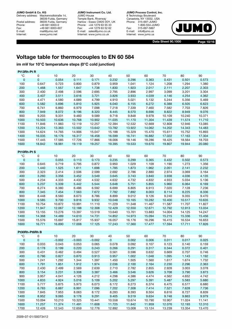
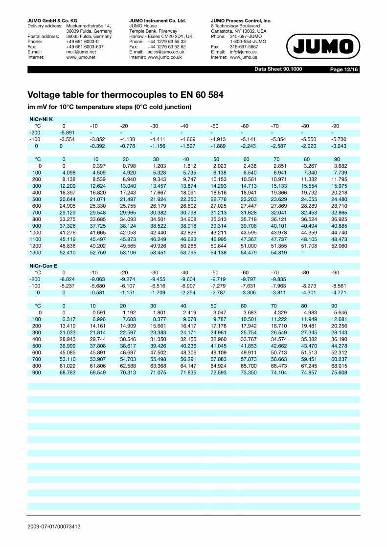
Voltage table for thermocouples to EN 60 584im mV for 10°C temperature steps (0°C cold junction)
Pt13Rh-Pt R°C 0 10 20 30 40 50 60 70 80 90
0 0 0.054 0.111 0.171 0.232 0.296 0.363 0.431 0.501 0.573100 0.647 0.723 0.800 0.879 0.959 1.041 1.124 1.208 1.294 1.380200 1.468 1.557 1.647 1.738 1.830 1.923 2.017 2.111 2.207 2.303300 2.400 2.498 2.596 2.695 2.795 2.896 2.997 3.099 3.201 3.304400 3.407 3.511 3.616 3.721 3.826 3.933 4.039 4.146 4.254 4.362500 4.471 4.580 4.689 4.799 4.910 5.021 5.132 5.244 5.356 5.469600 5.582 5.696 5.810 5.925 6.040 6.155 6.272 6.388 6.505 6.623700 6.741 6.860 6.979 7.098 7.218 7.339 7.460 7.582 7.703 7.826800 7.949 8.072 8.196 8.320 8.445 8.570 8.696 8.822 8.949 9.076900 9.203 9.331 9.460 9.589 9.718 9.848 9.978 10.109 10.240 10.371
1000 10.503 10.636 10.768 10.902 11.035 11.170 11.304 11.439 11.574 11.7101100 11.846 11.983 12.119 12.257 12.394 12.532 12.669 12.808 12.946 13.0851200 13.224 13.363 13.502 13.642 13.782 13.922 14.062 14.202 14.343 14.4831300 14.624 14.765 14.906 15.047 15.188 15.329 15.470 15.611 15.752 15.8931400 16.035 16.176 16.317 16.458 16.599 16.741 16.882 17.022 17.163 17.3041500 17.445 17.585 17.726 17.866 18.006 18.146 18.286 18.425 18.564 18.7031600 18.842 18.981 19.119 19.257 19.395 19.533 19.670 19.807 19.944 20.080
Pt10Rh-Pt S°C 0 10 20 30 40 50 60 70 80 90
0 0 0.055 0.113 0.173 0.235 0.299 0.365 0.432 0.502 0.573100 0.645 0.719 0.795 0.872 0.950 1.029 1.109 1.190 1.273 1.356200 1.440 1.525 1.611 1.698 1.785 1.873 1.962 2.051 2.141 2.232300 2.323 2.414 2.506 2.599 2.692 2.786 2.880 2.974 3.069 3.164400 3.260 3.356 3.452 3.549 3.645 3.743 3.840 3.938 4.036 4.135500 4.234 4.333 4.432 4.532 4.632 4.732 4.832 4.933 5.034 5.136600 5.237 5.339 5.442 5.544 5.648 5.751 5.855 5.960 6.064 6.169700 6.274 6.380 6.486 6.592 6.699 6.805 6.913 7.020 7.128 7.236800 7.345 7.454 7.563 7.672 7.782 7.892 8.003 8.114 8.225 8.336900 8.448 8.560 8.673 8.786 8.899 9.012 9.126 9.240 9.355 9.470
1000 9.585 9.700 9.816 9.932 10.048 10.165 10.282 10.400 10.517 10.6351100 10.754 10.872 10.991 11.110 11.229 11.348 11.467 11.587 11.707 11.8271200 11.947 12.067 12.188 12.308 12.429 12.550 12.671 12.792 12.913 13.0341300 13.155 13.276 13.397 13.519 13.640 13.761 13.883 14.004 14.125 14.2471400 14.368 14.489 14.610 14.731 14.852 14.973 15.094 15.215 15.336 15.4561500 15.576 15.697 15.817 15.937 16.057 16.176 16.296 16.415 16.534 16.6531600 16.771 16.890 17.008 17.125 17.243 17.360 17.477 17.594 17.711 17.826
Pt30Rh-Pt6Rh B°C 0 10 20 30 40 50 60 70 80 90
0 0 -0.002 - 0.003 - 0.002 - 0 0.002 0.006 0.011 0.017 0.025100 0.033 0.043 0.053 0.065 0.078 0.092 0.107 0.123 0.140 0.159200 0.178 0.199 0.220 0.243 0.266 0.291 0.317 0.344 0.372 0.401300 0.431 0.462 0.494 0.527 0.561 0.596 0.632 0.669 0.707 0.746400 0.786 0.827 0.870 0.913 0.957 1.002 1.048 1.095 1.143 1.192500 1.241 1.292 1.344 1.397 1.450 1.505 1.560 1.617 1.674 1.732600 1.791 1.851 1.912 1.974 2.036 2.100 2.164 2.230 2.296 2.363700 2.430 2.499 2.569 2.639 2.710 2.782 2.855 2.928 3.003 3.078800 3.154 3.231 3.308 3.387 3.466 3.546 3.626 3.708 3.790 3.873900 3.957 4.041 4.126 4.212 4.298 4.386 4.474 4.562 4.652 4.742
1000 4.833 4.924 5.016 5.109 5.202 5.297 5.391 5.487 5.583 5.6801100 5.777 5.875 5.973 6.073 6.172 6.273 6.374 6.475 6.577 6.6801200 6.783 6.887 6.991 7.096 7.202 7.308 7.414 7.521 7.628 7.7361300 7.845 7.953 8.063 8.172 8.283 8.393 8.504 8.616 8.727 8.8391400 8.952 9.065 9.178 9.291 9.405 9.519 9.634 9.748 9.863 9.9791500 10.094 10.210 10.325 10.441 10.558 10.674 10.790 10.907 11.024 11.1411600 11.257 11.374 11.491 11.608 11.725 11.842 11.959 12.076 12.193 12.3101700 12.426 12.543 12.659 12.776 12.892 13.008 13.124 13.239 13.354 13.470

2009-07-01/00073412
Page 11/16Data Sheet 90.1000
JUMO GmbH & Co. KGDelivery address: Mackenrodtstraße 14,
36039 Fulda, GermanyPostal address: 36035 Fulda, GermanyPhone: +49 661 6003-0Fax: +49 661 6003-607E-mail: [email protected]: www.jumo.net
JUMO Instrument Co. Ltd.JUMO HouseTemple Bank, RiverwayHarlow - Essex CM20 2DY, UKPhone: +44 1279 63 55 33Fax: +44 1279 63 52 62E-mail: [email protected]: www.jumo.co.uk
JUMO Process Control, Inc.8 Technology BoulevardCanastota, NY 13032, USAPhone: 315-697-JUMO
1-800-554-JUMOFax: 315-697-5867E-mail: [email protected]: www.jumo.us
Voltage table for thermocouples to EN 60 584im mV for 10°C temperature steps (0°C cold junction)
Cu-Con T°C 0 -10 -20 -30 -40 -50 -60 -70 -80 -90
-200 -5.603 - - - - - - - - --100 -3.378 -3.656 -3.923 -4.177 -4.419 -4.648 -4.865 -5.069 -5.261 -5.4390 0 -0.383 -0.757 -1.121 -1.475 -1.819 -2.152 -2.475 -2.788 -3.089
°C 0 10 20 30 40 50 60 70 80 900 0 0.391 0.789 1.196 1.611 2.035 2.467 2.908 3.357 3.813
100 4.277 4.749 5.227 5.712 6.204 6.702 7.207 7.718 8.235 8.757200 9.286 9.820 10.360 10.905 11.456 12.011 12.572 13.137 13.707 14.281300 14.860 15.443 16.030 16.621 17.217 17.816 18.420 19.027 19.638 20.252
Fe-Con J°C 0 -10 -20 -30 -40 -50 -60 -70 -80 -90
-200 -7.890 - - - - - - - - --100 -4.632 -5.036 -5.426 -5.801 -6.159 -6.499 -6.821 -7.122 -7.402 -7.6590 0 -0.501 -0.995 -1.481 -1.960 -2.431 -2.892 -3.344 -3.785 -4.215
°C 0 10 20 30 40 50 60 70 80 900 0 0.507 1.019 1.536 2.058 2.585 3.115 3.649 4.186 4.725
100 5.268 5.812 6.359 6.907 7.457 8.008 8.560 9.113 9.667 10.222200 10.777 11.332 11.887 12.442 12.998 13.553 14.108 14.663 15.217 15.771300 16.325 16.879 17.432 17.984 18.537 19.089 19.640 20.192 20.743 21.295400 21.846 22.397 22.949 23.501 24.054 24.607 25.161 25.716 26.272 26.829500 27.388 27.949 28.511 29.075 29.642 30.210 30.782 31.356 31.933 32.513600 33.096 33.683 34.273 34.867 35.464 36.066 36.671 37.280 37.893 38.510700 39.130 39.754 40.382 41.013 41.647 42.283 42.922 43.563 44.207 44.852
2009-07-01/00073412
Page 12/16Data Sheet 90.1000
JUMO GmbH & Co. KGDelivery address: Mackenrodtstraße 14,
36039 Fulda, GermanyPostal address: 36035 Fulda, GermanyPhone: +49 661 6003-0Fax: +49 661 6003-607E-mail: [email protected]: www.jumo.net
JUMO Instrument Co. Ltd.JUMO HouseTemple Bank, RiverwayHarlow - Essex CM20 2DY, UKPhone: +44 1279 63 55 33Fax: +44 1279 63 52 62E-mail: [email protected]: www.jumo.co.uk
JUMO Process Control, Inc.8 Technology BoulevardCanastota, NY 13032, USAPhone: 315-697-JUMO
1-800-554-JUMOFax: 315-697-5867E-mail: [email protected]: www.jumo.us
Voltage table for thermocouples to EN 60 584im mV for 10°C temperature steps (0°C cold junction)
NiCr-Ni K°C 0 -10 -20 -30 -40 -50 -60 -70 -80 -90
-200 -5.891 - - - - - - - - --100 -3.554 -3.852 -4.138 -4.411 -4.669 -4.913 -5.141 -5.354 -5.550 -5.730
0 0 -0.392 -0.778 -1.156 -1.527 -1.889 -2.243 -2.587 -2.920 -3.243
°C 0 10 20 30 40 50 60 70 80 900 0 0.397 0.798 1.203 1.612 2.023 2.436 2.851 3.267 3.682
100 4.096 4.509 4.920 5.328 5.735 6.138 6.540 6.941 7.340 7.739200 8.138 8.539 8.940 9.343 9.747 10.153 10.561 10.971 11.382 11.795300 12.209 12.624 13.040 13.457 13.874 14.293 14.713 15.133 15.554 15.975400 16.397 16.820 17.243 17.667 18.091 18.516 18.941 19.366 19.792 20.218500 20.644 21.071 21.497 21.924 22.350 22.776 23.203 23.629 24.055 24.480600 24.905 25.330 25.755 26.179 26.602 27.025 27.447 27.869 28.289 28.710700 29.129 29.548 29.965 30.382 30.798 31.213 31.628 32.041 32.453 32.865800 33.275 33.685 34.093 34.501 34.908 35.313 35.718 36.121 36.524 36.925900 37.326 37.725 38.124 38.522 38.918 39.314 39.708 40.101 40.494 40.885
1000 41.276 41.665 42.053 42.440 42.826 43.211 43.595 43.978 44.359 44.7401100 45.119 45.497 45.873 46.249 46.623 46.995 47.367 47.737 48.105 48.4731200 48.838 49.202 49.565 49.926 50.286 50.644 51.000 51.355 51.708 52.0601300 52.410 52.759 53.106 53.451 53.795 54.138 54.479 54.819 - -
NiCr-Con E°C 0 -10 -20 -30 -40 -50 -60 -70 -80 -90
-200 -8.824 -9.063 -9.274 -9.455 -9.604 -9.719 -9.797 -9.835-100 -5.237 -5.680 -6.107 -6.516 -6.907 -7.279 -7.631 -7.963 -8.273 -8.561
0 0 -0.581 -1.151 -1.709 -2.254 -2.787 -3.306 -3.811 -4.301 -4.771
°C 0 10 20 30 40 50 60 70 80 900 0 0.591 1.192 1.801 2.419 3.047 3.683 4.329 4.983 5.646
100 6.317 6.996 7.683 8.377 9.078 9.787 10.501 11.222 11.949 12.681200 13.419 14.161 14.909 15.661 16.417 17.178 17.942 18.710 19.481 20.256300 21.033 21.814 22.597 23.383 24.171 24.961 25.754 26.549 27.345 28.143400 28.943 29.744 30.546 31.350 32.155 32.960 33.767 34.574 35.382 36.190500 36.999 37.808 38.617 39.426 40.236 41.045 41.853 42.662 43.470 44.278600 45.085 45.891 46.697 47.502 48.306 49.109 49.911 50.713 51.513 52.312700 53.110 53.907 54.703 55.498 56.291 57.083 57.873 58.663 59.451 60.237800 61.022 61.806 62.588 63.368 64.147 64.924 65.700 66.473 67.245 68.015900 68.783 69.549 70.313 71.075 71.835 72.593 73.350 74.104 74.857 75.608

2009-07-01/00073412
Page 13/16Data Sheet 90.1000
JUMO GmbH & Co. KGDelivery address: Mackenrodtstraße 14,
36039 Fulda, GermanyPostal address: 36035 Fulda, GermanyPhone: +49 661 6003-0Fax: +49 661 6003-607E-mail: [email protected]: www.jumo.net
JUMO Instrument Co. Ltd.JUMO HouseTemple Bank, RiverwayHarlow - Essex CM20 2DY, UKPhone: +44 1279 63 55 33Fax: +44 1279 63 52 62E-mail: [email protected]: www.jumo.co.uk
JUMO Process Control, Inc.8 Technology BoulevardCanastota, NY 13032, USAPhone: 315-697-JUMO
1-800-554-JUMOFax: 315-697-5867E-mail: [email protected]: www.jumo.us
Tolerance classesfor thermocouples (0°C cold junction) to EN 60 584
Thermocouple Class 1Operating range Tolerance (±)1
copper/constantan T -40 to + 350°C 0.5°C or 0.004 x ltliron/constantan J -40 to + 750°C 1.5°C or 0.004 x ltlnickel-chrome/constantan E -40 to + 800°C 0.5°C or 0.004 x ltlnickel-chrome/nickel K -40 to +1000°C 1.5°C or 0.004 x ltlplatinum-13% rhodium/platinum R 0 to +1600°C 1 °C or [1+(t-1100) x 0.003]°Cplatinum-10% rhodium/platinum S 0 to +1600°C 1 °C or [1+(t-1100) x 0.003]°Cplatinum-30% rhodium/platinum-6% rhodium B - -
Thermocouple Class 2Operating range Tolerance (±)1
copper/constantan T -40 to + 350°C 1 °C or 0.0075 x ltliron/constantan J -40 to + 750°C 2.5°C or 0.0075 x ltlnickel-chrome/constantan E -40 to + 900°C 1 °C or 0.0075 x ltlnickel-chrome/nickel K -40 to +1200°C 2.5°C or 0.0075 x ltlplatinum-13% rhodium/platinum R 0 to +1600°C 1.5°C or 0.0025 x tplatinum-10% rhodium/platinum S 0 to +1600°C 1.5°C or 0.0025 x tplatinum-30% rhodium/platinum-6% rhodium B +600 to +1700°C 1.5°C or 0.0025 x t
Thermocouple Class 32
Operating range Tolerance (±)1
copper/constantan T -200 to +40°C 1 °C or 0.015 x ltliron/constantan J -200 to +40°C 2.5°C or 0.015 x ltlnickel-chrome/constantan E -200 to +40°C 1 °C or 0.015 x ltlnickel-chrome/nickel K -200 to +40°C 2.5°C or 0.015 x ltlplatinum-13% rhodium/platinum R - -platinum-10% rhodium/platinum S - -platinum-30% rhodium/platinum-6% rhodium B +600 to +1700°C 4 °C or 0.005 x t
The standard tolerance for thermocouples corresponds to DIN 43 760 or EN 60 584, Class 2.Restricted tolerance to Class 1 is possible on mineral-insulated thermocouples.
1. The tolerance is the specified value in °C or the percentage based on the actual temperature in °C,whichever is larger.
2. Thermocouples and thermocouple wires are usually supplied conforming to the tolerances according to the table abovefor the temperature range above -40°C.At temperatures below -40°C, the deviations for thermocouples of the same material may exceed the tolerances for Class 3.Where thermocouples according to tolerance classes 1, 2 and/or 3 are required, this has to be specified by the user;specially selected material is then used.
2009-07-01/00073412
Page 14/16Data Sheet 90.1000
JUMO GmbH & Co. KGDelivery address: Mackenrodtstraße 14,
36039 Fulda, GermanyPostal address: 36035 Fulda, GermanyPhone: +49 661 6003-0Fax: +49 661 6003-607E-mail: [email protected]: www.jumo.net
JUMO Instrument Co. Ltd.JUMO HouseTemple Bank, RiverwayHarlow - Essex CM20 2DY, UKPhone: +44 1279 63 55 33Fax: +44 1279 63 52 62E-mail: [email protected]: www.jumo.co.uk
JUMO Process Control, Inc.8 Technology BoulevardCanastota, NY 13032, USAPhone: 315-697-JUMO
1-800-554-JUMOFax: 315-697-5867E-mail: [email protected]: www.jumo.us
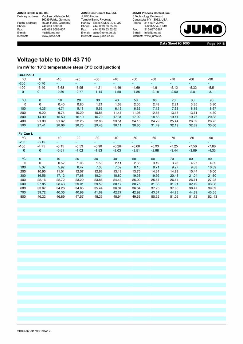
Voltage table to DIN 43 710 im mV for 10°C temperature steps (0°C cold junction)
Cu-Con U°C 0 -10 -20 -30 -40 -50 -60 -70 -80 -90
-200 -5.70 - - - - - - - - --100 -3.40 -3.68 -3.95 -4.21 -4.46 -4.69 -4.91 -5.12 -5.32 -5.51
0 0 -0.39 -0.77 -1.14 -1.50 -1.85 -2.18 -2.50 -2.81 -3.11
°C 0 10 20 30 40 50 60 70 80 900 0 0.40 0.80 1.21 1.63 2.05 2.48 2.91 3.35 3.80
100 4.25 4.71 5.18 5.65 6.13 6.62 7.12 7.63 8.15 8.67200 9.20 9.74 10.29 10.85 11.41 11.98 12.55 13.13 13.71 14.30300 14.90 15.50 16.10 16.70 17.31 17.92 18.53 19.14 19.76 20.38400 21.00 21.62 22.25 22.88 23.51 24.15 24.79 25.44 26.09 26.75500 27.41 28.08 28.75 29.43 30.11 30.80 31.49 32.19 32.89 33.60
Fe-Con L°C 0 -10 -20 -30 -40 -50 -60 -70 -80 -90
-200 -8.15 - - - - - - - - --100 -4.75 -5.15 -5.53 -5.90 -6.26 -6.60 -6.93 -7.25 -7.56 -7.86
0 0 -0.51 -1.02 -1.53 -2.03 -2.51 -2.98 -3.44 -3.89 -4.33
°C 0 10 20 30 40 50 60 70 80 900 0 0.52 1.05 1.58 2.11 2.65 3.19 3.73 4.27 4.82
100 5.37 5.92 6.47 7.03 7.59 8.15 8.71 9.27 9.83 10.39200 10.95 11.51 12.07 12.63 13.19 13.75 14.31 14.88 15.44 16.00300 16.56 17.12 17.68 18.24 18.80 19.36 19.92 20.48 21.04 21.60400 22.16 22.72 23.29 23.86 24.43 25.00 25.57 26.14 26.71 27.28500 27.85 28.43 29.01 29.59 30.17 30.75 31.33 31.91 32.49 33.08600 33.67 34.26 34.85 35.44 36.04 36.64 37.25 37.85 38.47 39.09700 39.72 40.35 40.98 41.62 42.27 42.92 43.57 44.23 44.89 45.55800 46.22 46.89 47.57 48.25 48.94 49.63 50.32 51.02 51.72 52. 43

2009-07-01/00073412
Page 15/16Data Sheet 90.1000
JUMO GmbH & Co. KGDelivery address: Mackenrodtstraße 14,
36039 Fulda, GermanyPostal address: 36035 Fulda, GermanyPhone: +49 661 6003-0Fax: +49 661 6003-607E-mail: [email protected]: www.jumo.net
JUMO Instrument Co. Ltd.JUMO HouseTemple Bank, RiverwayHarlow - Essex CM20 2DY, UKPhone: +44 1279 63 55 33Fax: +44 1279 63 52 62E-mail: [email protected]: www.jumo.co.uk
JUMO Process Control, Inc.8 Technology BoulevardCanastota, NY 13032, USAPhone: 315-697-JUMO
1-800-554-JUMOFax: 315-697-5867E-mail: [email protected]: www.jumo.us
Electrical TemperatureMeasurementwith thermocouples andresistance thermometers
Matthias NauElectrical temperature sensors have becomeindispensable in automation and domesticengineering, as well as in production technol-ogy. As a result of the rapid expansion of au-tomation in recent years, they have becomefirmly established in industrial engineering.
Fig. 13: PublicationElectrical temperature measurementwith thermocouplesand resistance thermometers
It is therefore particularly important that theuser can select the product that best fits hisapplication from the large variety of for avail-able products for electrical temperature mea-suremen.
166 pages this publication covers the theoret-ical fundamentals of electrical temperaturemeasurement, the practical construction oftemperature sensors, their standardization,tolerances and styles.
In addition, it describes in detail the differentfittings for electrical thermometers, their clas-sification to DIN and the great variety of appli-cations. The book includes an extensivesection with tables for voltage and resistanceseries to DIN and EN, thus making it a valu-able guide both for the experienced practicalengineer and the newcomer to the field ofelectrical temperature measurement.You can order a copy under Sales No. 90/00085081, or download it from www.jumo.net
Because of the high handling costs, schools,institutes and universities are asked to place abulk order.
Error Analysis of a Temperature MeasurementSystemwith worked examples
Gerd SchellerThis 40-page publication helps in the evalua-tion of measurement uncertainty, particularlythrough the worked examples in Chapter 3.Where problems arise, we are glad to discussspecific problems with our customers, and toprovide practical advice.
Fig. 14: PublicationError analysis of a temperature measure-ment system, with worked examples
In order to be able to make comparable mea-surements, their quality must be establishedthrough details of the measurement uncer-tainty. The ISO/BIPM “Guide to the Expressi-on of Uncertainty in Measurement”, publishedin 1993 and usually referred to as GUM, intro-duced a standardized method for the deter-mination and definition of measurementuncertainty. This method was adopted by ca-libration laboratories around the world. Howe-ver, the application requires a certain level ofmathematical understanding.
Further chapters present the topic of measu-rement uncertainty in a simplified and easilyunderstandable fashion for all users of tempe-rature measurement systems.Errors in the installation of the temperaturesensors and the connections to the evaluationelectronics lead to increased errors in measu-rement. To these must be added the measu-rement uncertainty components of the sensorand of the evaluation electronics itself. Theexplanation of the various components ofmeasurement uncertainty is followed by someworked examples.Knowledge of the various measurementuncertainty components and their magnitu-des enable the user to reduce individual com-ponents through the selection of equipmentor altered installation conditions. The decisivefactor is always, which level of measurementuncertainty is acceptable for a specific mea-surement task. For instance, if a standardspecifies tolerance limits for the deviation of atemperature from a nominal value, then themeasurement uncertainty of the method usedfor temperature measurement should not belarger than 1/3 of the tolerance.
You can order a copy underSales No. 90/00415704 or download from www.jumo.net
Because of the high handling costs, schools,institutes and universities are asked to place abulk order.
2009-07-01/00073412
Page 16/16Data Sheet 90.1000
JUMO GmbH & Co. KGDelivery address: Mackenrodtstraße 14,
36039 Fulda, GermanyPostal address: 36035 Fulda, GermanyPhone: +49 661 6003-0Fax: +49 661 6003-607E-mail: [email protected]: www.jumo.net
JUMO Instrument Co. Ltd.JUMO HouseTemple Bank, RiverwayHarlow - Essex CM20 2DY, UKPhone: +44 1279 63 55 33Fax: +44 1279 63 52 62E-mail: [email protected]: www.jumo.co.uk
JUMO Process Control, Inc.8 Technology BoulevardCanastota, NY 13032, USAPhone: 315-697-JUMO
1-800-554-JUMOFax: 315-697-5867E-mail: [email protected]: www.jumo.us
German Calibration Service(DKD) at JUCHHEIM
Certification laboratory fortemperatureRaised quality expectations, improved mea-surement technology and, of course, qualityassurance systems, such as ISO 9000, makeincreasing demands on the documentation ofprocesses and the monitoring of measuringdevices.In addition, there are increasing calls fromcustomers for high product quality standards.Particularly stringent demands arise fromISO 9000 and EN 45 000, whereby measure-ments must be traceable to national or inter-national standards. This provides the legalbasis for obliging suppliers and manufactur-ers (of products that are subject to processeswhere temperature is relevant) to check alltesting devices, which can affect the productquality, before use or at certain intervals. Gen-erally, this is done by calibrating or adjustingusing certified devices. Because of the highdemand for calibrated instruments and thelarge number of instruments to be calibrated,the state laboratories have insufficient capac-ity. The industry has therefore establishedand also supports special calibration labora-tories which are linked to the German Calibra-tion Service (DKD) and are subordinate to thePTB (Physikalisch-Technische-Bundesan-stalt) for all aspects of instrumentation.
The certification laboratory of the GermanCalibration Service at JUMO has carried outcalibration certification for temperature since1992. This service provides fast and econom-ical certification for everyone.DKD calibration certificates can be issued forresistance thermometers, thermocouples,measurement sets, data loggers and temper-ature block calibrators within the range -80 to +1100°C. The traceability of the refer-ence standard is the central issue here. AllDKD calibration certificates are recognized asdocuments of traceability, without any furtherspecifications. The DKD calibration laboratoryat JUMO has the identification DKD-K-09501-04 and is accredited to DIN EN ISO/IEC17 025.