Embed Size (px)
Citation preview
Constructing Process Models from Distributed Design Activity
Ph. D. DissertationPh.D. Candidate: Michael CummingFaculty of Architecture, Delft University of TechnologyDelft, The [email protected]
Title of Ph.D. Proposal (April 14, 1999):“Design Process Models for Architectural Practice.”
Committee Members Professors Ömer Akin (chair), Steven Fenves, David Garlan (Carnegie Mellon University), and Associate Professor Rudi Stouffs (Delft University of Technology).
This copy printed: December 31, 2004

ii
iii.
List of Figures ........................................................................... ix
Abstract ..........................................................................................1
Acknowledgments.....................................................................3
Dissertation thesis ....................................................................5
Chapter 1 Research definition..................................................................7
1.1 Motivation ............................................................................71.1.1 Introduction ............................................................71.1.2 Coordination of complex processes .......................71.1.3 Provision of design support while avoiding
negative consequences ............................................81.1.4 Gathering of process histories ................................8
1.2 Research problems................................................................91.2.1 Building flexible and dynamic online teams..........91.2.2 Determining design entity states ..........................101.2.3 Separating state-defining mechanisms from
entity content ......................................................... 111.3 Research scope ...................................................................12
1.3.1 Concentration on entity state determination.........121.3.2 Avoidance of handling the semantics of
entity state..............................................................121.3.3 Avoidance of role semantics ................................13
Chapter 2 Background ...............................................................................15
2.1 Integrated design systems...................................................152.1.1 IBDE.....................................................................152.1.2 STEP and IFC’s....................................................162.1.3 SEED project........................................................162.1.4 The overall SEED approach.................................172.1.5 The SEED-Pro (SP) module.................................192.1.6 Technologies in SEED-Config.............................212.1.7 Process aspects of SEED......................................23
2.2 Process modeling in design ................................................262.2.1 Introduction to the concept of ‘process’...............262.2.2 Process representations ........................................272.2.3 Simple representations .........................................272.2.4 Network representations such as CPM.................282.2.5 IDEF methods ......................................................302.2.6 Statecharts ............................................................312.2.7 Petri nets...............................................................312.2.8 CPNs and hierarchical decomposition .................32
2.3 Collaborative design theory................................................33
iv
2.3.1 Introduction ..........................................................332.3.2 Design methodologies ..........................................342.3.3 Cognitive models of design..................................362.3.4 Handbooks of professional practice .....................372.3.5 Social processes in design ....................................382.3.6 Coordination theory..............................................392.3.7 Design processes from a top-down perspective ...422.3.8 Design processes from a bottom-up perspective..43
2.4 Peer-to-peer software..........................................................452.4.1 Introduction ..........................................................452.4.2 What does P2P mean for computing? ..................452.4.3 JXTA by Sun Microsystems ................................46
2.5 Wisdom of crowds ..............................................................492.5.1 Relevance to collaborative design........................50
2.6 Centralized and distributed systems compared ..................512.6.1 Factors that promote the centralized approach
to collaborative design ..........................................512.6.2 Disadvantages of centralized systems ..................532.6.3 Advantages of distributed systems.......................542.6.4 Disadvantages of distributed systems ..................552.6.5 Conclusions regarding centralization and
decentralization .....................................................562.7 Related work: design support and coordination systems....56
2.7.1 Adaptive workflow...............................................562.7.2 Action workflow approach to process
coordination...........................................................572.7.3 Thesis by Tay-Sheng Jeng....................................592.7.4 Peer-to-peer projects in JXTA..............................59
Chapter 3 Application requirements ...................................................63
3.1 Introduction ........................................................................633.1.1 Application content ..............................................633.1.2 Application development method ........................63
3.2 Creation of a social context ................................................643.2.1 Complex processes and distributed control..........643.2.2 Process management involves communication
of process content between involved parties........643.2.3 Collaborative design processes involve
‘stakeholders’ assuming roles...............................653.3 Structured representations in design...................................66
3.3.1 Product hierarchies...............................................673.3.2 Process Hierarchies ..............................................673.3.3 Organizational hierarchies....................................68
3.4 Changing state of design entities ........................................683.4.1 Design entities defined .........................................683.4.2 Entities must be able to change state....................69
v.
3.4.3 Explicit state change mechanisms for design entities ........................................................70
3.4.4 Role, input and policy attributes for design entities ........................................................70
3.4.5 Basing state changes on user input.......................713.4.6 Linking and ‘bundling’ of entities........................713.4.7 Socially mediated and automated state change ....723.4.8 Task dependencies................................................723.4.9 Variability of state-transition models...................723.4.10 State models as simple state-transition loops.......73
3.5 Structured representations of design entities ......................733.5.1 Hierarchies of design representations ..................73
3.6 Communication between users...........................................743.6.1 Communication of large amounts of information 743.6.2 Asynchronous contributions.................................743.6.3 Decentralized configuration of software
and information .....................................................74
Chapter 4 Actors, use cases, and required objects ....................77
4.1 Introduction ........................................................................774.2 System actors......................................................................77
4.2.1 Peer.......................................................................774.3 Use cases.............................................................................78
4.3.1 Create design entity..............................................784.3.2 Create a structured container for
process-related information ..................................794.3.3 Assume role in a design entity .............................814.3.4 Make input for design entity state change............824.3.5 Link design entity to another design entity ..........834.3.6 Create a state-transition model.............................84
4.4 Required objects as described in use cases.........................854.4.1 Domain objects.....................................................854.4.2 Interface Objects ..................................................874.4.3 Control Objects ....................................................87
Chapter 5 Application design and implementation .....................89
5.1 What was implemented ......................................................895.1.1 Role of JXTA .......................................................895.1.2 Design Process Modeler (DPM) application........895.1.3 Peergroups............................................................905.1.4 Peergroup hierarchies...........................................915.1.5 State change mechanisms.....................................925.1.6 Process of defining input constraints ...................945.1.7 Information links ..................................................965.1.8 Managing data with ‘Content Storage’ ................97
5.2 Implementation decisions and alternatives.........................97
vi
5.2.1 Peergroups............................................................985.2.2 Stakeholder involvement: peers, roles,
and policies............................................................985.2.3 State change..........................................................995.2.4 DPM’s single path approach ..............................1005.2.5 Choice points......................................................1005.2.6 Security and privileges .......................................102
Chapter 6 Constructing process models by linking entities 105
6.1 Introduction ......................................................................1056.1.1 Information needs in Design ..............................105
6.2 Hierarchical peergroups....................................................1066.2.1 Design projects as information containers .........1066.2.2 Uses for hierarchical peergroups........................106
6.3 Design entity management ...............................................1076.3.1 User defined types..............................................1076.3.2 Deletion and abandonment of entities................1076.3.3 Iteration of entities .............................................1096.3.4 Reuse of entities (using prototypes) ...................109
6.4 Entity state ........................................................................1126.4.1 Determining state ...............................................1126.4.2 Link and input state changes ..............................1126.4.3 Parallel vs. sequential processes in DPM...........1136.4.4 Inputs seen as a type of voting system ...............113
6.5 Constructing process models ............................................1146.5.1 Prototypes and organizational memory:
policies and links................................................. 1146.5.2 Organizational memory vs. bootstrapping
from nothing ........................................................ 1156.5.3 Building structures using constraint links ..........1156.5.4 Sub-entity / sequential links:
branch out/in structures....................................... 1156.5.5 Planning vs. execution........................................1176.5.6 Chat messages ....................................................1176.5.7 Convergence in groups.......................................118
Chapter 7 Application testing and validation ............................... 119
7.1 Introduction to testing.......................................................1197.2 Introduction to TOI...........................................................1197.3 TOI and student processes ................................................120
7.3.1 Overall nature of these processes .......................1207.3.2 Aspects modeled for TOI by DPM ....................1217.3.3 TOI state-transition loop models........................122
7.4 Test specifics.....................................................................1257.4.1 Pre-test tasks.......................................................125
vii.
7.4.2 Test 1: Basic functionality of DPM....................1267.4.3 Test 2: Error production tasks ............................1307.4.4 Test 3: Integration test........................................131
7.5 Testing results ...................................................................1357.5.1 Things that worked well during testing..............1357.5.2 Things worked less well during testing..............1357.5.3 Safety in testing vs. usability of
distributed systems ..............................................1377.5.4 Bootstrapping of peergroups ..............................1377.5.5 Transmission of data between peers...................1377.5.6 Peergroup size and information specificity........1387.5.7 Revisions to software after testing .....................139
Chapter 8 Conclusion ...............................................................................143
8.1 Discussion of results .........................................................1438.1.1 Role of P2P.........................................................1438.1.2 Aspects impaired by P2P....................................1438.1.3 Aspects helped by a P2P implementation ..........1448.1.4 Solution to the reliability problem?....................1448.1.5 Interactive nature of DPM’s process..................1458.1.6 Leveraging external technologies.......................146
8.2 Contributions ....................................................................1478.2.1 Implementation of a working prototype
for design coordination .......................................1478.2.2 Provision of a process coordination framework.1478.2.3 Interactive collaborative modeling tool..............1478.2.4 Environment to represent and establish
organizational norms...........................................1478.2.5 Building of user-configured online teams..........147
8.3 Future research agenda .....................................................1488.3.1 Increase the reliability of information transfer...1488.3.2 Build more sophisticated prototype
mechanisms .........................................................1488.3.3 Explore information persistence.........................1488.3.4 Simplify the process of modeling
process loops .......................................................148
Chapter 9 References ...............................................................................149
Chapter 10 Appendices ..............................................................................157
10.1 Appendix A: Instructions for installing Design Process Modeler (DPM)........................................15710.1.1 Introduction ........................................................15710.1.2 Obtaining the software .......................................15710.1.3 Prerequisites for running the DPM application..15710.1.4 Configuration of JXTA ......................................158
viii
10.1.5 Reconfiguration..................................................16110.2 Appendix B: Package and class descriptions ...................163
10.2.1 dpm.container.tree..............................................16310.2.2 dpm.content ........................................................16310.2.3 dpm.content.advertisement.................................16410.2.4 dpm.content.constraint .......................................16510.2.5 dpm.content.state................................................16610.2.6 dpm.dpmApp.desktop ........................................16610.2.7 dpm.dpmApp.desktop.forms ..............................16710.2.8 dpm.peer.............................................................168
10.3 Appendix C: User interface forms....................................17010.3.1 New User Named Entity Form...........................17010.3.2 New Peergroup Form .........................................17110.3.3 New sub-entity relation Form. ...........................17110.3.4 New sequential relation Form. ...........................17210.3.5 New Constraint Link Form ................................17210.3.6 New Information Link Form..............................17310.3.7 Show Links Form...............................................17310.3.8 History Viewer Form .........................................17410.3.9 New Policy Form ...............................................17410.3.10 New Role Form ..................................................17510.3.11 New Input Form .................................................175
10.4 Appendix D: Information panels ......................................17710.4.1 DPM Information Panel .....................................17710.4.2 Petri net Loop Information Panel .......................177
10.5 Appendix E: Non-TOI sample state-transition loops .......17910.6 Appendix F: Sample advertisements ................................180
10.6.1 Design entity advertisements .............................18010.6.2 Advertisements linked to particular
design entities ......................................................18110.6.3 Advertisements linking entities..........................185
ix.
List of Figures
Fig. 1 Top-down and bottom-up design team-forming processes. ......................................................................... 10
Fig. 2 Separation of state determination mechanisms from content. .................................................................... 13
Fig. 3 In integrated generative systems, iterative processes involving Specification, Generation, and Evaluation phases are supported (Flemming et al., 2000, p.7). ....... 17
Fig. 4 Overall SEED architecture (Flemming et al., 2000, p.13). ......................................... 19
Fig. 5 Architectural programming process as supported by SEED-Pro (right), compared to a traditional process (left) (Akin et al., 1995, p.154). ............................................... 21
Fig. 6 Relationship between a building entity and associations with nodes of a technology hierarchy. The technology tree represents available construction technologies; building entities are associated with appropriate ‘and’ or ‘or’ paths through this technology tree. Similar to: (Fenves & Rivard, 2004, Fig. 4, p.10). ............................................. 22
Fig. 7 Simple node and arrow process diagram for a lump sum architectural design contract (Canadian Architectural Councils, 1995, vol.2, p.4). ............................................. 28
Fig. 8 Activity-on-arrow process diagram. ............................... 29Fig. 9 Activity-on-node process diagram. ................................. 29Fig. 10 IDEF3 process representation (KBSI, 1998). ................ 31Fig. 11 Simple statechart. ............................................................ 31Fig. 12 Simple place/transition Petri net before and after firing of
a transition, showing input and output places (Reisig, 1998, p.17). ...................................................................... 32
Fig. 13 Hierarchical Petri net using transition substitution. ....... 33Fig. 14 Spiral model of design as applied to software development
(Boehm & Hansen, 2001, p.6). ....................................... 35Fig. 15 Action and reflection cycles in design (Smith, 2004). ... 35Fig. 16 Components of a cognitive information processing system
(Akin, 1986, p.13). .......................................................... 37Fig. 17 Process model based on a professional contractual
arrangement (Canadian Architectural Councils, 1995, vol.2, p.7). ........................................................................ 38
Fig. 18 Peergroups as logical partitions of the top-level ‘world’ peergroup. ........................................................................ 47
x
Fig. 19 Commitment-based process loops found in ActionWorks (Action Technologies, 1998). .......................................... 58
Fig. 20 UML diagram of peers and their roles. .......................... 66Fig. 21 A product hierarchy, under the relation ‘componentOf.’ 67Fig. 22 A process hierarchy, under the relation ‘doBefore.’ ...... 68Fig. 23 An organizational hierarchy under the relation
‘reportsTo.’ ...................................................................... 68Fig. 24 Interdependency of tasks and products in
design descriptions. ......................................................... 69Fig. 25 State change based on Petri net-based constraints in which
incoming arrows represent constraints. .......................... 70Fig. 26 Interaction diagram: Create design entity. ...................... 78Fig. 27 Interaction diagram: Create a structured container for
process-related information. ........................................... 80Fig. 28 Interaction diagram: Assume role in a design entity. ..... 81Fig. 29 Interaction diagram: Make input for design entity
state change. ..................................................................... 82Fig. 30 Interaction diagram: Link design entity to another
design entity. .................................................................... 83Fig. 31 Interaction diagram: Create a state-transition model. .... 84Fig. 32 Link constraints. .............................................................. 93Fig. 33 Input constraints that specify which roles must
contribute to specific transitions of an entity’s state-transition loop. ................................................................. 93
Fig. 34 Top-level state change method from DPM’s Java code. 94Fig. 35 Link constraint. ................................................................ 96Fig. 36 Choice point constructed using a mutual exclusion
structure. ........................................................................ 101Fig. 37 State determination method. ..........................................112Fig. 38 Policies and linked entities from a prototype used to
recreate new entity structures. .......................................114Fig. 39 Complex constraint-linked entity network. ...................115Fig. 40 Sub-entity relation in DPM. The black dots signify the
current states of the entities. ...........................................116Fig. 41 Alternative diagram showing sub-entity relation. .........116Fig. 42 Sequential relation between entities in DPM ................116Fig. 43 Alternative diagram showing sequential relation. ........117Fig. 44 Branch-out and Branch-in precedence structures based on
sequential relations. ........................................................117Fig. 45 TOI course process. ....................................................... 121Fig. 46 Assignment process. ...................................................... 122Fig. 47 Examination process. .................................................... 122Fig. 48 TOI_Course state-transition loop. ................................ 123Fig. 49 TOI_Assignment state-transition loop. ........................ 123Fig. 50 TOI_Examination state-transition loop. ....................... 124Fig. 51 One possible peergroup organization for the
integration test. .............................................................. 132Fig. 52 Revised peergroup node refresh code. .......................... 140
xi.
Fig. 53 Basic JXTA configuration panel. .................................. 158Fig. 54 Advanced JXTA configuration panel. .......................... 159Fig. 55 Rendezvous/relay JXTA configuration panel. ............. 160Fig. 56 Security JXTA configuration panel. ............................. 161Fig. 57 Typical local user cache in JXTA. ................................ 162Fig. 58 UML diagram of package: dpm.container.tree ............ 163Fig. 59 UML diagram of package: dpm.content ....................... 164Fig. 60 UML diagram of package: dpm.content.advertisement 165Fig. 61 UML diagram of package: dpm.content.constraint ..... 166Fig. 62 UML diagram of package: dpm.content.state .............. 166Fig. 63 UML diagram (abridged) of package:
dpm.dpmApp.desktop ................................................... 167Fig. 64 UML diagram of package:
dpm.dpmApp.desktop.forms ......................................... 168Fig. 65 UML diagram of package: dpm.peer ............................ 169Fig. 66 Top Frame Form. ........................................................... 170Fig. 67 New Design Entity Form. ............................................. 171Fig. 68 New Peergroup Form. ................................................... 171Fig. 69 New sub-entity relation form. ....................................... 172Fig. 70 New sequential relation Form. ...................................... 172Fig. 71 New Constraint Link Form. .......................................... 173Fig. 72 New Information Link Form. ........................................ 173Fig. 73 Show Links Form. ......................................................... 174Fig. 74 History Viewer Form. .................................................... 174Fig. 75 New Policy Form. .......................................................... 175Fig. 76 New Role Form. ............................................................ 175Fig. 77 New Input Form. ........................................................... 176Fig. 78 DPM Information Panel. ............................................... 177Fig. 79 Petri net Loop Information Panel. ................................ 178Fig. 80 Design Task state-transition loop. ................................. 179Fig. 81 Design Product state-transition loop. ........................... 179

xii
1.
Abstract
Collaborative design is a complex cognitive and social activity that requires coordination of both processes and products between its participants. Information required for this coordinative activity are descriptions of the various tasks and products found within a design project, and of the current state of these entities. State descriptions can arise from technical analysis, perhaps employing automated, machine-based methods, or can arise from a social process of consensual, collaborative assessment that results in design team members applying informal linguistic descriptions to processes. In the event that no automated process exists for state determination, then members of the design team must work together and find a mutually agreeable assessment of state. With this information designers are better able to determine the progress and status of a design process, and to assess their roles and responsibilities within a design team.
This research describes the design and implementation of a design support tool that enables distributed teams to collaboratively determine the state of design entities, such as tasks and products. The tool is role-based, and enables users to communicate simple looped state-transition models that they feel suitably describe the possible states and transitions that a design entity could experience. These state models can describe the degree of completion, degree of acceptance within a team, or progress with respect to a series of milestones. By attaching entities to simple state-transition loops, users make input based on simple questions about the state of individual entities, rather than complex ones arising from the interaction of entities. Complex branching process structures can be created by composing entities. The tool automatically handles state assessment of complex, linked compositions of entities, while users handle assessment of simple, non-linked entities. It provides users with information regarding design state and structure, and supports a form of bottom-up design coordination that requires no centralized policies or inputs, prior to deployment.

2.
3.
Acknowledgments
This research would not have been completed without the loving support of my wife Cornelia Peckart.
I thank my advisor, Professor Ömer Akin for working with me over many years, and providing helpful and intelligent direction at every turn.
I also wish to thank the other members of my thesis committee: Professors Steven Fenves, David Garlan, and Rudi Stouffs. The quality of their contributions and influence cannot be overemphasized.
Special thanks to Professor Ulrich Flemming for providing leadership within the intellectually formative SEED project, for defining the relationship between architectural design and software engineering, and for exploration of the technical issues and design strategies out of which complex software is born.
Also very important to my intellectual development were fellow student members of the SEED team at Carnegie Mellon University. These friends include: Rana Sen, Magd Donia, Ye Zhang, Halil Erhan, Jonah Tsai, Sheng-fen Chien, James Snyder, Hoda Moustapha, Zeyno Aygen, Han Kiliççöte, Ipek Özkaya, and Hugues Rivard. A more interesting or more intelligent group of graduate students would be hard to find. They made the years spent in Pittsburgh golden ones that allowed many doors to be opened and exciting concepts to be explored.
Special thanks to Robert Ries and Patty Murphy for opening up your homes and hearts to our friends and family.
Thanks to Professor Sevil Sariyildiz, Chair of Technical Design and Informatics, Faculty of Architecture at TU Delft for her support and encouragement. Also to Bige Tunçer and Özer Ciftcioglu for many enlightening discussions over the nature of information and design, and to Ernst Janssen Groesbeek and Jan Poot for organizing test sessions within TOI, on short notice.
Thanks to Professors Ramesh Krishnamurti, Robert Woodbury, and Luis Rico-Gutierrez for being sympathetic at crucial times, and to Darlene Covington-Davis, Liz Fox, and Judy Kampert, of the School of Architecture for being supportive in a particularly open and kind way.
Thanks to Eric Griffiths and Van Woods of USACERL for providing useful input during the evolution of this research, and within the SEED-Pro project.
This research was sponsored in part by the US Army Corps of Engineers Construction Engineering Research Laboratory (USACERL). The National Science Foundation through the former Engineering Design Research Center (EDRC), and the Institute for Complex Engineered Systems (ICES) at Carnegie Mellon University provided additional funds.

4.
The Dutch Organization for Scientific Research (Nederlandse Organisatie voor Wetenschappelijk Onderzoek: NWO) provided funding under the project ‘Dynamic Digital Design Representations’ coordinated by Rudi Stouffs.
The views and conclusions contained herein are those of the author and should not be interpreted as representing official policies or endorsements, either expressed or implied, of the funding agencies.
5.
Dissertation thesis
Collaborative design practice takes place within dynamic social and technical environments, involving complex interactions between wide varieties of interested parties. In order to manage collaborative design, and in order for designers to work successfully within it, it is necessary to have information on the content and structure of design entities such as tasks and products, as well as their current state.
It is often difficult to determine this state, since most design entities do not have self-describing states, have no automated means of determining their state, or may have high degrees of ambiguity, even to well-informed design team participants. Without automated means of determining entity state, design team members must collaborate on deciding what the state should be. This should be role-based such that a person’s input is based on a specific role that has been assumed within the social context of the design team. This information is required for design coordination, both from a top-down and bottom-up perspective. Supporting design requires providing resources for coordinating design projects as a whole, as well as coordinating individual relationships between members of a design team.
At the beginning of design projects it may not be clear what the content, structure, or state of tasks and products should be. One aspect of collaborative design processes is how design task and product information structures are constructed incrementally, using the social and cognitive resources of the design team.
Collaborative design processes have both static and dynamic aspects. Processes can change substantially due to evolving design requirements, team participants, and other contextual factors. Processes can also remain static and can become design practice norms. In creative design practice it is often unclear whether to employ proven processes from the past, or to explore new ways of doing things.
Processes such as those required to determine state and to assign roles are often expensive, since they are generally not computer supported, and often depend on face-to-face contact to arrive at common ground within the team. An important aspect of face-to-face contact between design team members—despite possible expense—is that team members are better able to construct common understandings of design problems that can be essential in avoiding misunderstandings and errors. Face-to-face contact between design team members is important, or is unlikely to be replaced by peer-to-peer on-line interactions. However, enabling designers to collaborate on determination of design entity state in a geographically distributed, and asynchronous fashion, can provide useful design support, whatever the geographical distribution of a design team.

6.
7.
1 Research definition
1.1 Motivation
1.1.1 Introduction
My motivation for this research comes primarily from my own experience of architectural design practice in Canada, the UK and Germany. During this time (1981-1994) it occurred to me that certain types of design support tools were not available to architects. The problems which these imagined tools would address, seemed to revolve around issues of design process:
1. How to represent design processes such that a designer could understand their overall structure, could plan them adequately, could predict which resources they would likely require, and could view how far along in a design process a particular design had progressed.
2. How to enable the lessons learned from past design processes to inform cur-rent design processes.
As I later learned, these are issues are of concern in many other domains, such as computer-supported collaborative work, software engineering, and of business management.
1.1.2 Coordination of complex processes
Complex design processes need to be coordinated. One of the motivations of this research is to try to generalize collaborative approaches such that they can be used to coordinate complex activity in a variety of domains.
Often design processes if viewed in isolation may not seem that complicated. What can make them overwhelmingly complex are their linked dependencies to other products and processes. One approach to design support and design coordination is for software to deal with the semantic content of design processes, and to try to steer them in preferred directions. Another approach is to coordinate whatever processes designers might want to pursue, and attempt to support them in ways not dependent on their meaning.
The first approach could be called a ‘semantic’ or ‘knowledge-based’ approach, while the second could be called a ‘syntactic’ or ‘interaction-based’ approach. The syntactic approach is based on the nature of collaborative mechanisms rather than the meaning of that which is being coordinated. A syntactic approach to design process coordination is explored in this research. This is also one the principal motivations of the field called coordination science in which general patterns for coordinating various types of work are explored.
8.
1.1.3 Provision of design support while avoiding negative consequences
To manage a process is to provide, however implicitly, a theory about what is involved in design. There is not, however, wide consensus shared within academia and practice, of a theory about what is involved in collaborative design. Such a theory is still in development. Development of various types of design support software is seen as an attempt for working towards such a theory and to arrive at a profession-wide consensus, rather than a software implementation of established theory.
Collaborative design is a difficult process to support, both because of its complexity, but because many designers, who are the consumers of design support, see their design processes as something not amenable to management or outside support. Designers’ objections to design management also concern issues of freedom, accountability, and effectiveness:• whether management introduces prescriptions into a design process for which
designers have not consented,• whether it reduces the flexibility of design approach and actually make design
teams less capable of handling complexity, and • whether design management has a negative effect on design quality, or
encourages design processes to develop in less interesting ways.
These are legitimate concerns. However, collaborative design is a large industry in all developed nations and has a significant role to play in productive economies. Support must be forthcoming for these processes, because they are so economically significant.
Collaborative design is not the only industry that has similar issues. It is not difficult to come up with examples of industries, which like collaborative design, seem to demand both high levels of creativity, combined with high degrees of organization and control. Examples of such industries are computer software development, media production, and product design. These industries demand intelligent and creative responses to enormously difficult problems, while also demanding that processes are organized in a such that their complexity does not overwhelm those participating in these processes. Since the design and construction industries are enormously important in most countries, managing their processes in a way that doesn’t decrease the quality or agility of these process is important. Computer-based tools and methods appear to be a promising way of doing this.
1.1.4 Gathering of process histories
Designers in practice acquire experience while they practice design. Their personal histories are important resources for them, as they maneuver through their design careers. These histories are often not recorded in archival type documents that future historians might be in a position to study.
Organizations find that their organizational histories are a valuable resource that can help explain how processes and products evolved to their current configuration, and how similar problems were addressed and solved in the past.
9.
Designers and the organizations that employ them, generally do not document this experience in any kind of systematized, or computer-readable format. Experience is recorded cognitively and conceptually in designers’ brains. This knowledge can quickly vanish when the designer dies or stops practicing. One advantage of process support tools is that they are in a position of gathering coherent historical data in a machine-readable format. If such data is gathered, it could become a useful resource for documenting and analyzing design practice, and for informing the design of future design support tools.
1.2 Research problems
1.2.1 Building flexible and dynamic online teams
Design teams, either virtual or real, are seen as the most important context in which collaborative design takes place. Without design teams, it is inconceivable that collaborative design could take place. Therefore, support for designers is seen as closely aligned with the issue of support for design teams.
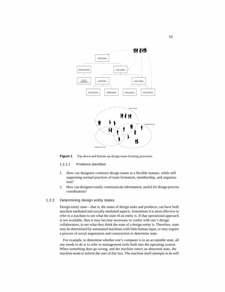
To support design teams, it is necessary to be able to form teams in a flexible manner, and to enable designers to join these teams easily. This need not be purely a top-down process. It is possible that design teams can be built incrementally as designers individually decide, and are allowed, to join them. All invitations to join a design team—that might come from a client or the partner in a design firm—are balanced by an acceptance or rejection of the invitation by the invited designer. How design teams are formed tends to be a highly interactive process that requires negotiation.
In addition to enable designers to construct teams, it is also necessary for team members to be able to communicate information required within the domain of design process coordination. This communication process should be an easy one, that doesn’t place undue cognitive or social burdens on designers.
It makes sense to enable computer-supported teams to interact online, since the Internet is the dominant communication medium of our age. The types of information that can be gleaned from it, and the types of inter-personal interactions it enables and encourages, grows almost daily.
10.
Figure 1 Top-down and bottom-up design team-forming processes.
1.2.1.1 Problems identified
1. How can designers construct design teams in a flexible manner, while still supporting normal practices of team formation, membership, and organiza-tion?
2. How can designers easily communicate information, useful for design process coordination?
1.2.2 Determining design entity states
Design entity state—that is, the states of design tasks and products, can have both machine mediated and socially mediated aspects. Sometimes it is most effective to refer to a machine to see what the state of an entity is. If that operational approach is not available, then it may become necessary to confer with one’s design collaborators, to see what they think the state of a design entity is. Therefore, state may be determined by automated machines with little human input, or may require a process of social negotiation and construction to determine state.
For example, to determine whether one’s computer is in an acceptable state, all one needs to do is to refer to management tools built into the operating system. When something does go wrong, and the machine enters an abnormal state, the machine tends to inform the user of this fact. The machine itself attempts to be self-
CAD manager
Chief Designer
Database manager
Chief detailer Plans manager
Services detailer Cladding detailer Plans assistant 1 Plans assistant 2
Databaseprogrammer
Detailing Group
Plans Group
Database Group
11.
regulating. However, to determine the state of one’s family, it is usually necessary to confer with the family members themselves. The family is a collective entity like a design team, but it is not self-regulating in the same sense as a computer is. Its ‘management’ requires active communication between its members.
As in many aspects of collaborative design, there are few tools to quantitatively assess the ‘state’ of such socially interactive systems as families and design teams. In such systems, the perceptions and interactive behaviors of individuals affect how they work as social units capable of problem solving.
One way of automating collaborative design, or at least to encourage it to avoid abnormal states, is to fully plan it in advance. In this way the plan becomes a kind of deterministic machine that has explicit and well-defined representations of states and state transitions. However, it is difficult to fully pre-plan a design process, if the intention is to maintain it as a creative design process, and to enable various collaborators to make meaningful, contextually appropriate input into it.
In the absence of quantifiable, or operational methods of assessing state, social negotiation becomes necessary for deciding the state their projects are in. This consensual social process is needed both for knowledge acquisition: ‘what is the informed opinion’, as well as for risk management: ‘how can the risk of making this decision be shared amongst other willing participants.’
1.2.2.1 Problems identified
1. How can design entities be arranged to have both machine-mediated and so-cially mediated states?
2. How can designers work together to determine the state of design entities?3. How can an application provide state changing mechanisms?
1.2.3 Separating state-defining mechanisms from entity content
This research aims to enable the coordination of a variety of process content. This coordination process is based on the idea that designers need to know what the state of design entities is, and that designers themselves play a role in determining this state.
In order to offer some kind of open, generalizable process, designers should be able to add their own design entities—ones appropriate for the design processes they experience. The application must provide state-changing mechanisms that can be applied to the variety of design content found in design practice. In this way the state-changing mechanisms can be generalized, while designers are free to add their own particular, context-dependent content.
There are three components to design entity content:
1. Names, and other attributes of the design entity.2. The structured relationships to other design entities, such as hierarchical rela-
tion, and other types of links.
12.
3. The state/transition model: the possible states and transitions that the design entity can enter into.
All of the above items should be modifiable by users of the application. The first two items are dependent on user input. The third point is a bit more challenging, and is less obvious how users might be able to contribute state/transition models. It is also not clear how the application can define either machine-based or socially-based state change mechanisms.
1.2.3.1 Problems identified
1. How do users add content to design entities? Of particular importance—how can they specify the states and transitions that entities can enter into?
1.3 Research scope
1.3.1 Concentration on entity state determination
This research concentrates on user-provided descriptions of state-changeable design entities, and the establishment of on-line communities that enable users to manage these entities collaboratively. This is seen as an important, even essential aspect of process management. However, there are other aspects of process management which could have been addressed, but have not been, such as:
1. Facilities for making detailed plans, and providing an ability to ‘re-plan.’ One problematic aspect of planning, is the cost of re-planning, which concerns the question about what to do when circumstances—assumed in the plan—change. Aspects of creative, dynamic design processes tend to make them less amenable to detailed planning. However, it is possible that using similar types of ideas in this dissertation, a plan-based approach could be completed.
2. Facilities for deriving plans from smaller process-related components.
1.3.2 Avoidance of handling the semantics of entity state
Users can add any kind of process content they want including state-transition ‘loops.’
One of the early criticisms of AI research software is the use of state descriptions that imply that a knowledge-based application acquires an understanding of states, based on the meaning of their state names. William Clancey describes this kind of state labeling in the context of the influential medical diagnosis expert system MYCIN. Clancey promotes the intellectual separation of what the application might ‘know’, and the descriptive, if not rhetorical labels applied by intelligent software designers (Clancey, 1997).
The application described in this research has been designed in this spirit. It works the same regardless of the content of any available state-transition loops. Since users can add any kind of loop, the application does not make any inferences about this user-added process content.
13.
1.3.3 Avoidance of role semantics
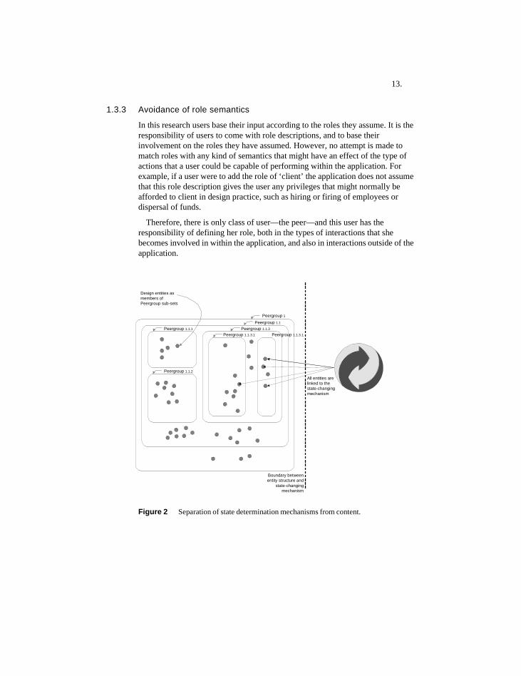
In this research users base their input according to the roles they assume. It is the responsibility of users to come with role descriptions, and to base their involvement on the roles they have assumed. However, no attempt is made to match roles with any kind of semantics that might have an effect of the type of actions that a user could be capable of performing within the application. For example, if a user were to add the role of ‘client’ the application does not assume that this role description gives the user any privileges that might normally be afforded to client in design practice, such as hiring or firing of employees or dispersal of funds.
Therefore, there is only class of user—the peer—and this user has the responsibility of defining her role, both in the types of interactions that she becomes involved in within the application, and also in interactions outside of the application.
Figure 2 Separation of state determination mechanisms from content.
State-changingmechanism
Peergroup 1Peergroup 1.1
Peergroup 1.1.1
Peergroup 1.1.2
Peergroup 1.1.3
Peergroup 1.1.3.1 Peergroup 1.1.3.1
Design entities asmembers ofPeergroup sub-sets
Boundary betweenentity structure and
state-changingmechanism
All entities arelinked to thestate-changingmechanism

14.
15.
2 Background
2.1 Integrated design systemsIntegrated design system attempt to structure and coordinate complex design projects and processes in a rational, well-ordered manner. There have been many such systems within the domains of architecture and building-related structural design. Stouffs and Krishnamurti (2001) point out that these often adopt an a-priori approach in which systems attempt to establish an agreement on concepts and their relationships, in order to offer a complete and uniform description of project data. Integration efforts are often inspired by the promise of computer-based systems for rationalizing design processes and organizing complex data.
2.1.1 IBDE
The IBDE project began in the late eighties at the Engineering Design Research Center (EDRC) at Carnegie Mellon University (Fenves et al., 1994). IBDE was not seen as a prototype for a commercial design system, but more as an experimental test-bed for the exploration of issues such as integration and communication between design agents. IBDE combines the work of various computer-based design agents that mirrors the inter-disciplinary nature of building design. These agents are divided into two classes: generators—those that contribute towards developing and refining design descriptions, and critics—agents that evaluate design descriptions as they emerge, and make redesign recommendations. The generator support tasks such as development of building design concepts (in the ARCHIPLAN module), to construction planning (in the PLANEX module). Critics include ones for providing constructability and structural evaluation.
IBDE research is critical of an approach to integrated design systems it calls ‘tool-centered.’ Tool-centered systems tightly couple available design tools and a design environment meant to integrate these tools. This is seen as restricting the evolution of tools, given that any tool is unlikely to fully address the range of problems found in practice, nor be standardized throughout an industry. Instead, a more flexible, more generalizable, and less prescriptive ‘problem-centered’ approach is taken in IBDE, in which tools can be integrated into a general framework as new tools develop. A problem-centered approach requires that tool-independent representations of information and process be developed.
IBDE concluded that tighter integration of design processes should not necessarily result in more consolidated and integrated organizations addressing design projects, but that there should be a common, formalized language developed for use between design team participants. Such a language could be used to standardize the communication of designer intent, of downstream consequences of design decisions, and of descriptions of the multiple functions in which design products usually participate (Fenves et al., 1994, p.227).
16.
2.1.2 STEP and IFC’s
STEP, the Standard for the Exchange of Product Model Data, is a comprehensive ISO standard (ISO 10303) that describes how to represent and exchange digital product information (Step Tools, 2004). STEP was conceived to reduce design and manufacturing errors due to data incompatibility between the various agents involved in product design. STEP presents a unifying effort started under the International Standards Organization (ISO) to produce an international standard for all aspects of technical product data. Nearly every major CAD/CAM system now contains a module to read and write data defined by one of the STEP Application Protocols (AP's).
The Industry Alliance for Interoperability (IAI) is a global, industry-based consortium for the construction and building management industries and aims to define object-oriented information models for data exchange. Its mission is to enable interoperability among processes of different professional domains, and to enable computer applications to share and exchange project information. The IAI's goals are to define, publish and promote a specification—called the Industry Foundation Classes (IFCs)—for sharing data throughout the project life cycle, globally, across disciplines and technical applications. The IFCs are used to assemble a project model in a neutral computer language that describes building project objects and represents common information requirements (IAI, 2004).
As Stouffs and Krishnamurti (2001) assert, the STEP/IFC effort is a prime example of a top-down, a-priori approach (2001, p.78). Such efforts depend on diverse parties coming together and agreeing on the semantics of a wide variety of product concepts and configurations. This consensus-based approach appears to take much effort. Yet, it is debatable whether such semantic-based agreement will be able to handle new product or computer technologies as they emerge, or whether this standardization effort will ultimately result in greater industrial productivity, quality, or agility.
2.1.3 SEED project‘The software Environment to Support the Early Phases in Building De-sign (SEED) aims at providing computational support for the early phas-es of in building design in all aspects that can benefit from such support. It especially intends to encourage an exploratory mode of design by mak-ing it easy for designers to generate and evaluate alternative design con-cepts and versions.’ (Flemming et al., 2000, p.1)
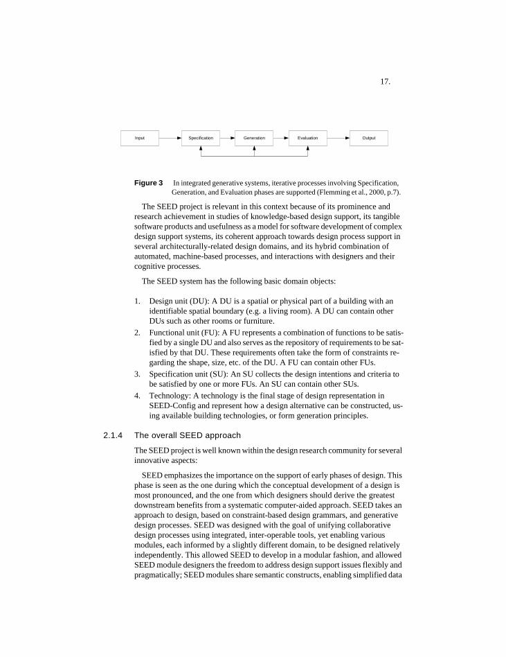
SEED is a computer-aided generative architectural design system, developed at Carnegie Mellon University, and at other institutions (Flemming & Woodbury, 1995) (Snyder, 1998) (Fenves, Rivard, Gomez, & Chiou, 1995). It features an open-ended modular architecture, where each module provides support for design activities taking place in early design phases. Each module consists of five main components: input, specification, generation, evaluation, and output. These are supported by a database to store and retrieve information, as well as a user interface to support the interaction with designers.
17.
Figure 3 In integrated generative systems, iterative processes involving Specification, Generation, and Evaluation phases are supported (Flemming et al., 2000, p.7).
The SEED project is relevant in this context because of its prominence and research achievement in studies of knowledge-based design support, its tangible software products and usefulness as a model for software development of complex design support systems, its coherent approach towards design process support in several architecturally-related design domains, and its hybrid combination of automated, machine-based processes, and interactions with designers and their cognitive processes.
The SEED system has the following basic domain objects:
1. Design unit (DU): A DU is a spatial or physical part of a building with an identifiable spatial boundary (e.g. a living room). A DU can contain other DUs such as other rooms or furniture.
2. Functional unit (FU): A FU represents a combination of functions to be satis-fied by a single DU and also serves as the repository of requirements to be sat-isfied by that DU. These requirements often take the form of constraints re-garding the shape, size, etc. of the DU. A FU can contain other FUs.
3. Specification unit (SU): An SU collects the design intentions and criteria to be satisfied by one or more FUs. An SU can contain other SUs.
4. Technology: A technology is the final stage of design representation in SEED-Config and represent how a design alternative can be constructed, us-ing available building technologies, or form generation principles.
2.1.4 The overall SEED approach
The SEED project is well known within the design research community for several innovative aspects:
SEED emphasizes the importance on the support of early phases of design. This phase is seen as the one during which the conceptual development of a design is most pronounced, and the one from which designers should derive the greatest downstream benefits from a systematic computer-aided approach. SEED takes an approach to design, based on constraint-based design grammars, and generative design processes. SEED was designed with the goal of unifying collaborative design processes using integrated, inter-operable tools, yet enabling various modules, each informed by a slightly different domain, to be designed relatively independently. This allowed SEED to develop in a modular fashion, and allowed SEED module designers the freedom to address design support issues flexibly and pragmatically; SEED modules share semantic constructs, enabling simplified data
Specification EvaluationGenerationInput Output

18.
exchange between modules. In order to arrive at this common logic, the overall design process was divided into distinct tasks or phases. A common architecture and interface was based on a uniform problem solving view (Flemming & Woodbury, 1995). They also enable and encourage design exploration through design alternative management, and design iteration. This iteration can occur both within a module, and between modules. SEED modules also share an ability to store and retrieve past solutions and problem sets, in the manner of case-based reasoning systems.
The combination of the above factors meant that the SEED system benefited from an interdisciplinary view of design, and from an interdisciplinary view of the types of academic approaches that must be brought together to advance the state of the art in CAD research.
2.1.4.1 Existing SEED modules
SEED is divided into domain-specific modules. Modules are expected to work both as stand-alone applications and as components in the larger system. SEED modules, once connected by a communication channel via a shared database, could be used together within an integrated design support system.
SEED being a collaborative system, assumes that different modules address different tasks. The expertise contained within SEED-Config (SC), SEED-Layout (SL), and SEED-Pro (SP) is quite distinct and maps to different pre-computational knowledge domains such as structural, construction, architectural, and requirements design.
SEED-Pro (SP): Design requirements and user specification design. Supports a task normally done by architectural designers, or by professional design requirements programmers, who, within the construction industry produce a document of design requirements called the ‘architectural program.’ This module has been developed within the School of Architecture, at Carnegie Mellon University (CMU) (Akin, Sen, Donia, & Zhang, 1995).
SEED-Layout (SL): Conceptual 2D or 2 1/2 D layout design. Supports a task normally done by architectural designers. This module was developed within the School of Architecture at CMU (Flemming & Chien, 1995).
SEED-Config (SC): Conceptual structural, and construction detailing design. Supports a task normally done by structural engineers and architectural detailers. This module is being developed within the Department of Civil and Environmental Engineering at CMU, and at the University of Adelaide, in Australia (Fenves et al., 1995).
19.
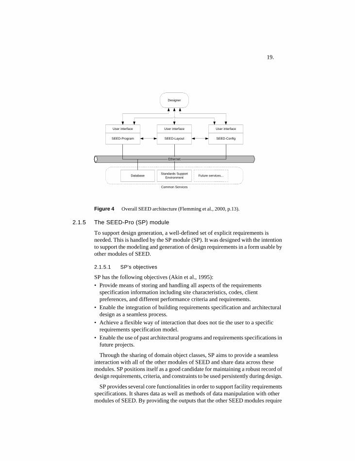
Figure 4 Overall SEED architecture (Flemming et al., 2000, p.13).
2.1.5 The SEED-Pro (SP) module
To support design generation, a well-defined set of explicit requirements is needed. This is handled by the SP module (SP). It was designed with the intention to support the modeling and generation of design requirements in a form usable by other modules of SEED.
2.1.5.1 SP’s objectives
SP has the following objectives (Akin et al., 1995):• Provide means of storing and handling all aspects of the requirements
specification information including site characteristics, codes, client preferences, and different performance criteria and requirements.
• Enable the integration of building requirements specification and architectural design as a seamless process.
• Achieve a flexible way of interaction that does not tie the user to a specific requirements specification model.
• Enable the use of past architectural programs and requirements specifications in future projects.
Through the sharing of domain object classes, SP aims to provide a seamless interaction with all of the other modules of SEED and share data across these modules. SP positions itself as a good candidate for maintaining a robust record of design requirements, criteria, and constraints to be used persistently during design.
SP provides several core functionalities in order to support facility requirements specifications. It shares data as well as methods of data manipulation with other modules of SEED. By providing the outputs that the other SEED modules require
User interface User interface User interface
Ethernet
Designer
Database Standards SupportEnvironment Future services...
Common Services
SEED-Program SEED-ConfigSEED-Layout
20.
as input and through the shared domain object classes and libraries in SEED, SP complements the basic steps of early design: architectural problem specification, two dimensional design and three dimensional configuration design.
Sharing of domain object classes, which represent entities like Functional Unit (FU), Design Unit (DU), and Specification Unit (SU) to enable SP to translate between organizational, functional, and spatial concepts.
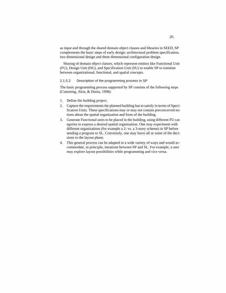
2.1.5.2 Description of the programming process in SP
The basic programming process supported by SP consists of the following steps (Cumming, Akin, & Donia, 1998):
1. Define the building project.2. Capture the requirements the planned building has to satisfy in terms of Speci-
fication Units. These specifications may or may not contain preconceived no-tions about the spatial organization and form of the building.
3. Generate Functional units to be placed in the building, using different FU cat-egories to express a desired spatial organization. One may experiment with different organizations (for example a 2- vs. a 3-story scheme) in SP before sending a program to SL. Conversely, one may leave all or some of the deci-sions to the layout phase.
4. This general process can be adapted in a wide variety of ways and would ac-commodate, in principle, iterations between SP and SL. For example, a user may explore layout possibilities while programming and vice versa.
21.
Figure 5 Architectural programming process as supported by SEED-Pro (right), compared to a traditional process (left) (Akin et al., 1995, p.154).
2.1.6 Technologies in SEED-Config
SEED-Config is the module within SEED that supports configuration design. The term ‘configuration design’ refers to the design of a three-dimensional building model in terms of spaces, subsystems, and actual physical components (Flemming et al., 2000, p.47). The inputs to SEED-Config are the requirements, specifications, and constraints for the overall structure stemming from the architectural program, space layout, and the massing definition (Fenves & Rivard, 2004, p.7).
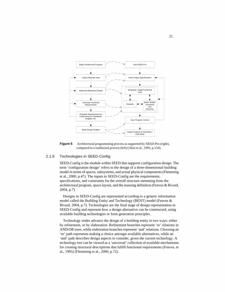
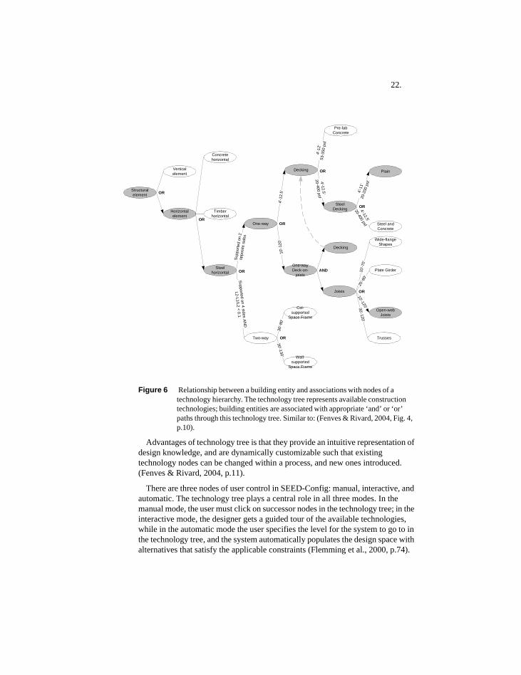
Designs in SEED-Config are represented according to a generic information model called the Building Entity and Technology (BENT) model (Fenves & Rivard, 2004, p.7). Technologies are the final stage of design representation in SEED-Config and represent how a design alternative can be constructed, using available building technologies or form generation principles.
Technology nodes advance the design of a building entity in two ways: either by refinement, or by elaboration. Refinement branches represent ‘or’ relations in AND/OR trees, while elaboration branches represent ‘and’ relations. Choosing an ‘or’ path represents making a choice amongst available alternatives, while an ‘and’ path describes design aspects to consider, given the current technology. A technology tree can be viewed as a ‘universal’ collection of available mechanisms for creating structural descriptions that fulfill functional requirements (Fenves, et al., 1995) (Flemming et al., 2000, p.72).
Begin Architectural Program
Collect Relevant Data
Determine Behavioral Needs
Generate FunctionalRequirements
Evalulate Requirements forConformance to Standards,
Budgets, etc.
State Design Problem
Start SEED-Pro
Enter Project Specifications
Save Program Version
Output Program to Data Base /Case Base
Instantiate / Adapt FunctionalUnits
EvaluateBuild / Modify
FunctionalUnit
Hierarchy
22.
Figure 6 Relationship between a building entity and associations with nodes of a technology hierarchy. The technology tree represents available construction technologies; building entities are associated with appropriate ‘and’ or ‘or’ paths through this technology tree. Similar to: (Fenves & Rivard, 2004, Fig. 4, p.10).
Advantages of technology tree is that they provide an intuitive representation of design knowledge, and are dynamically customizable such that existing technology nodes can be changed within a process, and new ones introduced. (Fenves & Rivard, 2004, p.11).
There are three nodes of user control in SEED-Config: manual, interactive, and automatic. The technology tree plays a central role in all three modes. In the manual mode, the user must click on successor nodes in the technology tree; in the interactive mode, the designer gets a guided tour of the available technologies, while in the automatic mode the user specifies the level for the system to go to in the technology tree, and the system automatically populates the design space with alternatives that satisfy the applicable constraints (Flemming et al., 2000, p.74).
Verticalelement
Structuralelement
Horizontalelement
Concretehorizontal
Timberhorizontal
Steelhorizontal
One-way
Two-way
Supp
orte
d on
2op
posi
te s
ides
Suppor ted o n 4 sides AND
L2- L1/L2 < 0.1
Decking
One-wayDeck-on-
joists10
'-120
'4'
-12.
5'
Pre-fabConcrete
SteelDecking
Decking
Joists
AND
4'-1
2'53
-350
psf
4' -12.5'
20-400 psf
Col-supported
Space Frame
Wall-supported
Space Frame
30'-8
0'
30'-130'
OR
OR
OR
OR
OR
Wide-flangeShapes
Plate Girder
Open-webJoists
Trusses
10'-7
0'25
'-80'
10'-120'30'-120'
OR
OR
Plain
Steel andConcrete
4'-1
1'20
-200
psf
4'-12.5'
20-400 psf
OR
23.
2.1.6.1 Discussion of the SEED-Config design process
SEED-Config processes are driven by technological norms. These norms are expressed in SEED-Config’s technology trees. A technology tree may deal with steel or concrete construction methods, and the knowledge contained within it is likely has developed over many years. For most users such norms appear to be a static body of knowledge, and for most purposes they can be considered as such. However, technologies—even those applied to routine designs—do change over time, sometimes substantially. In this case the technology trees will have to be revised. In some cases it is conceivable that a technology tree might have to be completely rearranged in order to handle a new technological or regulatory environment. Therefore, it is not always clear that technology trees can be kept up to date with incremental changes—such as adding new refinement or elaboration nodes to existing trees. In some cases fundamental reorganization might be required.
SEED-Config technologies are seen as available resources that can be used, rather than something that has to be developed within a design process itself. For many non-routine design projects, it may not be clear their designers know how to solve problems with existing technologies. In that case, a new technology may have to developed.
In SEED-Config functional and technological factors lead in the design process. This, of course is quite typical in engineering design contexts. However, it is not always the case in architectural design processes, in which formal and spatial ideas are sometimes explored with less concern about the construction technologies that might be required to instantiate these ideas.
SEED-Config emphasizes the engineering inputs and decision-making while placing less emphasis on the interactions between others on the design team such as architects. Ideally, architectural design processes seems to work best when there are early interactions between those on the team whose input might affect the design in fundamental ways. In the building and construction industry, structural engineers and architects are the two most prominent examples of such participants. Therefore, in principle design projects that require at least two different disciplines at the earliest stages—say at minimum the structural engineer and the architect. The manner in which these two parties interact needs to be a part of the basic user process for a design support application. Developments of SEED-Config in this direction are taking place in the work of Hugues Rivard (Fenves & Rivard, 2004, p.14).
2.1.7 Process aspects of SEED
Design processes are not explicitly modeled in SEED modules. That is, they do not present to their users models of actions that users are expected to perform, or representations of what the application is performing. They do have available paper-based reference and tutorial manuals describing how to use the applications to perform design tasks (Cumming et al., 1998; Donia, Flemming, Akin, Sen, & Cumming, 1998; Flemming, 1998; Flemming & Chien, 1998).

24.
SEED modules do not provide a deterministic process model for design, and do provide a large degree of flexibility in how design problems can be solved, using these tools. Despite this lack of determinism, all SEED modules though, share a similar approach to the design process. This approach is based on one of the basic ideas behind generative design: that one of the first tasks in design should be an attempt to formally define design problem requirements. Once this is done, these requirements provide input for automated or semi-automated generation of design solutions, based on constraints found within the requirements.
Each SEED module contains a problem specification component that enables designers to specify and modify dynamically the design problem to be solved. In addition, all have generation and evaluation components (Flemming & Chien, 1995).
For many processes in which requirements can be defined unambiguously, and generation algorithms are available, the generative approach is powerful and very productive. This is especially true in constraint-based layout generation, in which topological constraints between required spaces can be defined clearly, and relatively easily.
2.1.7.1 Designer control of the design process
SEED modules were designed from the beginning to have a clear idea of aspects of a design process that should be under the designer’s control and those that can easily be automated without loss of design quality or intelligent control. In SEED, human users provide intelligent control.
In generative systems, the basic idea is to automate some aspects of the design process. Therefore, it should be clear which aspects are controlled algorithmically, and which humans should control. In a SEED module the two aspects explicitly controlled by designers are:
1. the definition of problems and requirements, and 2. selection of preferred generated alternatives, such that they can be further re-
fined and elaborated.
This in general seems to be a good approach: leverage the capabilities of human designers using generative techniques, yet maintaining a clear position that the human designers still need to be in control.
The generative approach tends to be highly interactive: if the results generated are less than satisfactory (a common occurrence in generative design), then users adjust input constraints to see how they might affect the generative process. One of the interesting aspects of the behavior of generative systems is the aspect of unpredictability in their results: surprises that result from slight tweaking of the inputs, can be intellectually gratifyingly, and can help define the real meaning of the input constraints.
Design processes in generative systems such as the SEED modules, are hybrid manual/machine supported processes: they can move quickly, and iterate often
25.
between different modules, and within various process aspects within each module.
2.1.7.2 Routine design and SEED
‘The SEED-Config project (Woodbury & Chang, 1995) clearly demon-strated the promise of a generative design system for routine design tasks, which present a good starting point for work in this direction not only because they are conceptually and computationally manageable with current technologies, but also because so much of the daily practice of an architect is routine design’ (Flemming, 2004, p.10).
Design processes can be characterized by their level of innovation. The standard classification scheme involves the categories creative, innovative, and routine. See for instance (Dym & Levitt, 1991) and (Coyne, Rosenman, Radford, & Gero, 1987). These levels either can be decided at the outset, or can be an emergent product of the design processes themselves. These categories are not fixed—there exists a continuum between design processes that might change substantially from design project to project, to those that are quite stable and exhibit little change.
Innovation and creativity imply unpredictably in a design process. The greater the design team desires to pursue innovative design processes, the greater is the uncertainty among the design participants about how a design project should proceed, and how it might turn out.
Providing design process support in situations where the processes never change is much easier than in situations where they do. SEED modules tend to emphasize their utility within routine design projects. In routine design processes, the participants may have long experience, and work within conceptual frameworks that are unlikely to change dramatically. In routine design, the issue of design freedom is not normally relevant. Preconceived goals in such design situations are not really unwelcome constraints, but rather an essential feature of this type of design.
Routine design tends to occur when designers handle recurring building types (Flemming & Woodbury, 1995, p.147). These building types are common in the building industry, since they reuse tested design processes, design team configurations, materials, and assemblies. This reuse can save significant amounts of money. Designers though, must be careful not to allow the attractions of routine practice blind them to the improvements needed to maintain design competitiveness. As Klein points out, a reliance on routine design is certainly economically useful—especially in the short term—but can lead to antipathy towards innovation and the search for, perhaps subtle, improvements in product and process (Klein, Sayama, Faratin, & Bar-Yam, 2001).
An open question in design support systems is whether a design process support that is useful in routine situations can also be applied to more creative or intentionally innovative types of design processes.
26.
2.1.7.3 SEED’s changes to a traditional design process
The SEED generative design support tools encourage the early documentation of spatial data and assembling it into computer readable form. This data covers the names, areas, number, and spatial constraints for all the spaces to be included in the building. This data is usually available at an early design stage from a building’s design program—if one exists. In normal design practice it is the client’s responsibility to either provide this building program for the architect, at the start of her design process, or to contract this task to the architect or some other consultant.
In SL, once spaces are documented, they then can be laid out graphically according to their spatial constraints. This layout process in SL can be fully automated. This is in contrast to current design practice when using either manual or CAD tools, there is generally no automation in the layout of spaces: all required areas must be placed manually into a drawing.
This layout automation in SL enables the creation of alternative layouts very quickly, all satisfying given spatial constraints. SEED encourages the modeling of various alternative organizational and spatial structures, using the spaces which are to be included in the building. This automation of the layout process in SL is a fundamental change in how design is performed using SL. More empirical study is needed to come a deeper understanding of its advantages and disadvantages.
The SEED system is a multi-disciplinary system. It assumes a highly iterative process in which partially completed design entities can be communicated to other SEED modules, and to external tools and process. Therefore, it doesn’t assume a strict sequential process. However, it does assume that large amounts of information are gathered at the start, and constraints are constructed according to this information. Therefore, it is an information-led process: the greater the quantity and the quality of the information at the beginning, the greater the quality of the generation that takes place downstream.
2.2 Process modeling in design
2.2.1 Introduction to the concept of ‘process’
Notions of ‘process’, and ‘design process’ can be broad and wide-ranging. These notions do not necessarily converge into a concept that is compact and illuminating for current research purposes.
One definition of process: Etymology: Middle English ‘process’ from Middle French, from Latin ‘processus’, f, from ‘procedere.’ Date: 14th century. 1. Something going on. 2.A natural phenomenon marked by gradual changes that lead toward a particular result. 3.Aseries of actions or operations conducing to an end... (Merriam-Webster Inc., 1999).
Some definitions stress the operational or action-related aspect of design, such as Herbert Simon’s definition of a designer as “Everyone...who devises courses of action aimed at changing existing situations into preferred ones” (Simon, 1984).
27.
While others emphasize the cognitive activity required for designing that requires mental representations, search processes and strategies, to find solutions to design problems. Akin writes that a design process “connotes a comprehensive concept: the totality of the cognitive activities that occur during design” (Akin, 1991). Or “a reflective conversation with the situation” (Schön, 1983).
Design processes are usually seen as activities that are created and are developed in a social context, where social behaviors such as conflict, conflict resolution and consensus, are important factors in determining the nature of the design product produced. Lu and Jin write that engineering design and practice “consists of collaborative negotiation” (1998). While Lu writes that collaborative design is “...a socio-technical co-constructive process” (Lu, Udwadia, Burkett, Cai, & Jin, 1998).
“The activity of design (as in a design process) is commonly thought to be what the designer does, alone, at the drawing board... imagine instead that every individual with a voice in the design process is a kind of de-signer—the client, the engineer, the contractor, the inhabitants, the col-lege president, the fund-raiser and so on. The architect-designer, among other individuals, has the added responsibilities of coordinating all con-tributions and giving them some spatial expression. Design, then, is tak-ing place whenever any of these actors makes plans about the future en-vironment” (Cuff, 1991).
Processes also have a distinct meaning in computer science referring to an entity created during execution of a computer application: Hoare writes that a process is “The behavior pattern of an object insofar as it can be described in terms of the limited set of events selected by its alphabet... The actual occurrence of each event in the life of an object should be regarded as an instantaneous or an atomic action without duration” (1985). While Silberschatz and Peterson state: “a process is a program in execution... a program is a passive entity, while a process is an active entity. The execution of a process must progress in a sequential fashion” (1988).
2.2.2 Process representations
There are many different representations for processes. This is because the concept of process is a very broad one, which almost all domains address in some way. This is because most knowledge domains deal with events or activities that occur over time. This survey has a bias towards process representations with graphic representations, rather than more data structure oriented representations such as object oriented, e.g. (Gorti, Gupta, Kim, Sriram, & Wong, 1998), or knowledge-based ones, e.g. (Genesereth & Fikes, 1992). This bias is due to the position that architects, being often visually oriented, would probably prefer to manipulate processes graphically within an application, in the manner of modern GUI interfaces rather than as lower level data structures.
2.2.3 Simple representations
Architects in education and practice usually produce simple diagrams, which include boxes and arrows. These can be found in all professional practice handbooks e.g. (Canadian Architectural Councils, 1995), (American Institute of
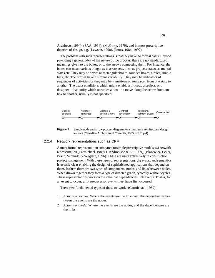
28.
Architects, 1994), (SAA, 1984), (McGinty, 1979), and in most prescriptive theories of design, e.g. (Lawson, 1990), (Jones, 1984, 1992).
The problem with such representations is that they have no formal basis. Beyond providing a general idea of the nature of the process, there are no standardized meanings given to the boxes, or to the arrows connecting them. For instance, the boxes can mean various things: as discrete activities, as projects states, as mental states etc. They may be drawn as rectangular boxes, rounded boxes, circles, simple lists, etc. The arrows have a similar variability. They may be indicators of sequences of activities, or they may be transitions of some sort, from one state to another. The exact conditions which might enable a process, a project, or a designer—that entity which occupies a box—to move along the arrow from one box to another, usually is not specified.
Figure 7 Simple node and arrow process diagram for a lump sum architectural design contract (Canadian Architectural Councils, 1995, vol.2, p.4).
2.2.4 Network representations such as CPM
A more formal representation compared to simple prescriptive models is a network representation (Carmichael, 1989), (Hendrickson & Au, 1989), (Blazewicz, Ecker, Pesch, Schmidt, & Weglarz, 1996). These are used extensively in construction project management. With these types of representations, the syntax and semantics is usually clear enabling the design of sophisticated applications that depend on them. In them there are two types of components: nodes, and links between nodes. When drawn together they form a type of directed graph, typically without cycles. These representations work on the idea that dependencies link events. That is, for an event to occur, all it predecessor events must have first occurred.
There two fundamental types of these networks (Carmichael, 1989):
1. Activity on arrow: Where the events are the links, and the dependencies be-tween the events are the nodes.
2. Activity on node: Where the events are the nodes, and the dependencies are the links.
Budgetapproval
Architectappointed
Briefing &design stages
Contractdocuments
Tendering/contract award Construction
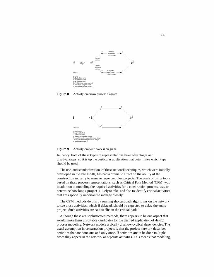
29.
Figure 8 Activity-on-arrow process diagram.
Figure 9 Activity-on-node process diagram.
In theory, both of these types of representations have advantages and disadvantages, so it is up the particular application that determines which type should be used.
The use, and standardization, of these network techniques, which were initially developed in the late 1950s, has had a dramatic effect on the ability of the construction industry to manage large complex projects. The goals of using tools based on these process representations, such as Critical Path Method (CPM) was in addition to modeling the required activities for a construction process, was to determine how long a project is likely to take, and also to identify critical activities that are especially important to manage closely.
The CPM methods do this by running shortest path algorithms on the network to see those activities, which if delayed, should be expected to delay the entire project. Such activities are said to ‘lie on the critical path.’
Although these are sophisticated methods, there appears to be one aspect that would make them unsuitable candidates for the desired application of design process modeling. Network models typically disallow cyclical dependencies. The usual assumption in construction projects is that the project network describes activities that are done one and only once. If activities are to be done multiple times they appear in the network as separate activities. This means that modeling
Choosearchitect
Approvebudget
Completepreliminaryarch. design
Choosestructuralengineer
Completepreliminarystruc. design
A. B.
C.
D.
E.
F.
G.
States:
A. StartB. Budget approvedC. Architect chosenD. Engineer chosenE. Architectural design startedF. Structural design startedG. Preliminary design started
A. B.
C.
D.
E.
F.
G.
Activities:
A. Start projectB. Approve budgetC. Choose architectD. Choose structural engineerE. Complete preliminary architectural designF. Complete preliminary structural designG. Start detailed design
30.
of iteration, which is seen as a major feature of design activity, cannot be done transparently.
2.2.5 IDEF methods
IDEF (Integrated Definition Methods) were originally developed in the 1970s and comprise a whole suite of methodologies and representations. Originally developed under contract for the US Air Force, they are now being developed by the company Knowledge-Based Systems Inc. (KBSI, 1998).
The IDEF system models the following aspects of organizations and enterprises (KBSI, 1998): IDEF (Integrated Computer-Aided Manufacturing (ICAM) DEFinition) is a group of methods used to perform modeling in support of enterprise integration. It was originally developed by the US Air Force Program for Integrated Computer Aided Manufacturing (ICAM).
There are actually 16 IDEF methods, running from IDEF0 through IDEF14 (and including IDEF1 and 1x). In practice, three IDEF methods form the core of IDEF use in the field. They are IDEF0: Systems from a functional and organizational perspective, IDEF1x: Design of data models and conceptual schema, and IDEF3: Process flows and object states and captures all temporal information, including precedence and causality relationships associated with enterprise processes.
For the purpose of process modeling, the IDEF3 method is the most suitable and is intended to capture the behavioral aspects of systems. It comprises two types of models: 1. a process flow description, and 2. an object state transition description. Process flow descriptions are composed of two elements: nodes and links. The nodes, represented as boxes, are termed ‘Units of Behavior’ (UOBs). These can be hierarchically composed of other UOBs. As well they can be ‘elaborated’ such that the participating objects and their relations are shown. Circles represent object states, and lines connecting circles are the state transition links (KBSI, 1998).
The IDEF methods are static modeling environments and construction of executable process models is not possible. According to the documentation for a colored Petri net (CPN) modeling application (Meta Software Corp., 1993), IDEF0 methods are similar to those of Petri nets, except that IDEF is a static modeling method and is unable to represent system behavior over time.
It is apparently common for CPNs and IDEF0 models to be used together to do systems modeling. The parts of a system design which can be understood statically are modeled using IDEF0, while the parts which require a dynamic execution, can be modeled using CPNs. The use of IDEF0 for the purpose of modeling sequences of activities is not recommended according to KBSI, Inc. (1998), although this usage is possible using the representation.
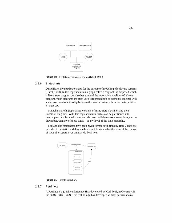
31.
Figure 10 IDEF3 process representation (KBSI, 1998).
2.2.6 Statecharts
David Harel invented statecharts for the purpose of modeling of software systems (Harel, 1988). In this representation a graph called a ‘higraph’ is proposed which is like a state diagram but also has some of the topological qualities of a Venn diagram. Venn diagrams are often used to represent sets of elements, together with some structured relationship between them—for instance, how two sets partition a larger set.
Statecharts are higraph-based versions of finite-state machines and their transition diagrams. With this representation, states can be partitioned into overlapping or subsumed states, and also arcs, which represent transitions, can be drawn between any of these states—at any level of the state hierarchy.
Higraph and statecharts have been given formal definitions by Harel. They are intended to be static modeling methods, and do not enable the view of the change of state of a system over time, as do Petri nets.
Figure 11 Simple statechart.
2.2.7 Petri nets
A Petri net is a graphical language first developed by Carl Petri, in Germany, in the1960s (Petri, 1962). This technology has developed widely, particular as a
3
Finalize Funding
1
Choose Site
Projectstarted
Pre-designcompleted
2
CompleteArchitectural
Program
Choose material
Choose texture
Choose color
Set budget
Calculatequantities
Set material costbudget allowance
cost
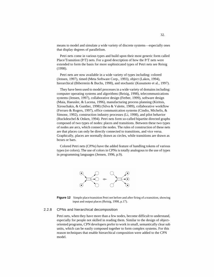
32.
means to model and simulate a wide variety of discrete systems—especially ones that display degrees of parallelism.
Petri nets come in various types and build upon their most generic form called Place/Transition (P/T) nets. For a good description of how the P/T nets were extended to form the basis for more sophisticated types of Petri nets see Reisig (1998).
Petri nets are now available in a wide variety of types including: colored (Jensen, 1997), timed (Meta Software Corp., 1993), object (Lakos, 1994), hierarchical (Biberstein & Buchs, 1998), and stochastic (Kusumoto et al., 1997).
They have been used to model processes in a wide variety of domains including: computer operating systems and algorithms (Reisig, 1998), telecommunications systems (Jensen, 1997), collaborative design (Ferber, 1999), software design (Maia, Haeusler, & Lucena, 1996), manufacturing process planning (Kiritsis, Xirouchakis, & Gunther, 1998) (Silva & Valette, 1989), collaborative workflow (Ferraro & Rogers, 1997), office communication systems (Cindio, Michelis, & Simone, 1992), construction industry processes (Li, 1998), and pilot behavior (Ruckdeschel & Onken, 1994). Petri nets form so-called bipartite directed graphs composed of two types of nodes: places and transitions. Between these two types of nodes are arcs, which connect the nodes. The rules of construction of these nets are that places can only be directly connected to transitions, and vice versa. Graphically, places are normally drawn as circles, while transitions are drawn as boxes or bars.
Colored Petri nets (CPNs) have the added feature of handling tokens of various types (or colors). The use of colors in CPNs is totally analogous to the use of types in programming languages (Jensen, 1996, p.9).
Figure 12 Simple place/transition Petri net before and after firing of a transition, showing input and output places (Reisig, 1998, p.17).
2.2.8 CPNs and hierarchical decomposition
Petri nets, when they have more than a few nodes, become difficult to understand, especially for people not skilled in reading them. Similar to the design of object-oriented programs, CPN developers prefer to work in small, semantically clear sub units, which can be easily composed together to form complex systems. For this reason techniques that enable hierarchical composition were added to the CPN model.
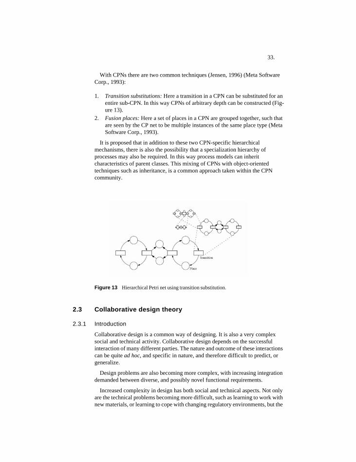
33.
With CPNs there are two common techniques (Jensen, 1996) (Meta Software Corp., 1993):
1. Transition substitutions: Here a transition in a CPN can be substituted for an entire sub-CPN. In this way CPNs of arbitrary depth can be constructed (Fig-ure 13).
2. Fusion places: Here a set of places in a CPN are grouped together, such that are seen by the CP net to be multiple instances of the same place type (Meta Software Corp., 1993).
It is proposed that in addition to these two CPN-specific hierarchical mechanisms, there is also the possibility that a specialization hierarchy of processes may also be required. In this way process models can inherit characteristics of parent classes. This mixing of CPNs with object-oriented techniques such as inheritance, is a common approach taken within the CPN community.
Figure 13 Hierarchical Petri net using transition substitution.
2.3 Collaborative design theory
2.3.1 Introduction
Collaborative design is a common way of designing. It is also a very complex social and technical activity. Collaborative design depends on the successful interaction of many different parties. The nature and outcome of these interactions can be quite ad hoc, and specific in nature, and therefore difficult to predict, or generalize.
Design problems are also becoming more complex, with increasing integration demanded between diverse, and possibly novel functional requirements.
Increased complexity in design has both social and technical aspects. Not only are the technical problems becoming more difficult, such as learning to work with new materials, or learning to cope with changing regulatory environments, but the
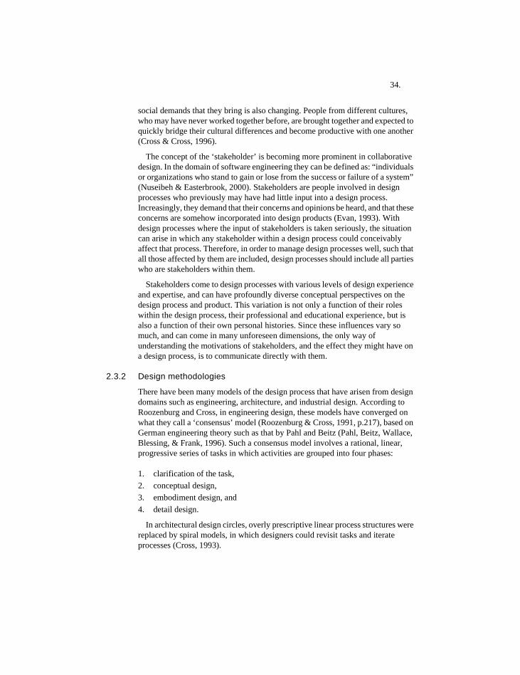
34.
social demands that they bring is also changing. People from different cultures, who may have never worked together before, are brought together and expected to quickly bridge their cultural differences and become productive with one another (Cross & Cross, 1996).
The concept of the ‘stakeholder’ is becoming more prominent in collaborative design. In the domain of software engineering they can be defined as: “individuals or organizations who stand to gain or lose from the success or failure of a system” (Nuseibeh & Easterbrook, 2000). Stakeholders are people involved in design processes who previously may have had little input into a design process. Increasingly, they demand that their concerns and opinions be heard, and that these concerns are somehow incorporated into design products (Evan, 1993). With design processes where the input of stakeholders is taken seriously, the situation can arise in which any stakeholder within a design process could conceivably affect that process. Therefore, in order to manage design processes well, such that all those affected by them are included, design processes should include all parties who are stakeholders within them.
Stakeholders come to design processes with various levels of design experience and expertise, and can have profoundly diverse conceptual perspectives on the design process and product. This variation is not only a function of their roles within the design process, their professional and educational experience, but is also a function of their own personal histories. Since these influences vary so much, and can come in many unforeseen dimensions, the only way of understanding the motivations of stakeholders, and the effect they might have on a design process, is to communicate directly with them.
2.3.2 Design methodologies
There have been many models of the design process that have arisen from design domains such as engineering, architecture, and industrial design. According to Roozenburg and Cross, in engineering design, these models have converged on what they call a ‘consensus’ model (Roozenburg & Cross, 1991, p.217), based on German engineering theory such as that by Pahl and Beitz (Pahl, Beitz, Wallace, Blessing, & Frank, 1996). Such a consensus model involves a rational, linear, progressive series of tasks in which activities are grouped into four phases:
1. clarification of the task,2. conceptual design,3. embodiment design, and 4. detail design.
In architectural design circles, overly prescriptive linear process structures were replaced by spiral models, in which designers could revisit tasks and iterate processes (Cross, 1993).
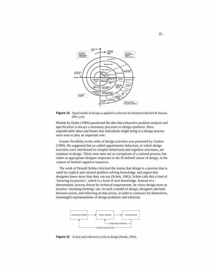
35.
Figure 14 Spiral model of design as applied to software development (Boehm & Hansen, 2001, p.6).
Models by Darke (1984) questioned the idea that exhaustive problem analysis and specification is always a necessary precursor to design synthesis. Here, unpredictable ideas and biases that individuals might bring to a design process were seen to play an important role.
Greater flexibility in the order of design activities was promoted by Guidon (1990). He suggested that so-called opportunistic behaviors, in which design activities were interleaved in complex behavioral and cognitive structures, are common in design. These were seen not as corruptions of a rational process, but rather as appropriate designer responses to the ill-defined nature of design, in the context of limited cognitive resources.
The work of Donald Schön criticized the notion that design is a process that is ruled by explicit and rational problem solving knowledge, and argues that designers know more than they can say (Schön, 1983). Schön calls this a kind of ‘knowing-in-practice’, which is a form of tacit knowledge. Instead of a deterministic process driven by technical requirements, he views design more as iterative ‘meaning-forming’ one. In such a model of design, designers alternate between action, and reflecting on that action, in order to construct for themselves, meaningful representations of design problems and solutions.
Figure 15 Action and reflection cycles in design (Smith, 2004).
Governing variable Action strategy Consequences
Single-loop reflection
Double-loop learning
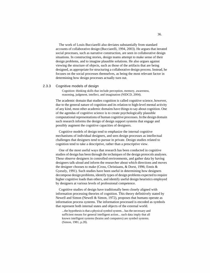
36.
The work of Louis Bucciarelli also deviates substantially from standard accounts of collaborative design (Bucciarelli, 1994, 2003). He argues that iterated social processes, such as narrative construction, are seen in collaborative design situations. In constructing stories, design teams attempt to make sense of their design problems, and to imagine plausible solutions. He also argues against viewing the structure of objects, such as those of the artifacts that are being designed, as appropriate for structuring a collaborative design process. Instead, he focuses on the social processes themselves, as being the most relevant factor in determining how design processes actually turn out.
2.3.3 Cognitive models of designCognition: thinking skills that include perception, memory, awareness, reasoning, judgment, intellect, and imagination (NIDCD, 2004).
The academic domain that studies cognition is called cognitive science, however, due to the general nature of cognition and its relation to high-level mental activity of any kind, most other academic domains have things to say about cognition. One of the agendas of cognitive science is to create psychologically plausible computational representations of human cognitive processes. In the design domain such research informs the design of design support systems that engage and possibly augment the cognitive capacities of designers.
Cognitive models of design tend to emphasize the internal cognitive mechanisms of individual designers, and sees design processes as intellectual challenges that designers tend to pursue in private. Design studies related to cognition tend to take a descriptive, rather than a prescriptive view.
One of the most useful ways that research has been conducted in cognitive studies of design has been through the techniques of the design protocols analyses. These observe designers in controlled environments, and gather data by having designers talk-aloud and inform the researcher about which directions and moves the designer chooses to make (Cross, Christiaans, & Dorst, 1996; Ennis & Gyeszly, 1991). Such studies have been useful in determining how designers decompose design problems, identify types of design problems expected to require higher cognitive loads than others, and identify useful design heuristics employed by designers at various levels of professional competence.
Cognitive studies of design have traditionally been closely aligned with information processing theories of cognition. This theory definitively stated by Newell and Simon (Newell & Simon, 1972), proposes that humans operate as information process systems. The information processed is encoded as symbols that represent both internal states and objects of the external world.
...the hypothesis is that a physical symbol system... has the necessary and sufficient means for general intelligent action... such data imply that all known intelligent systems (brains and computers) are symbol systems. (Simon, 1981, p.28).
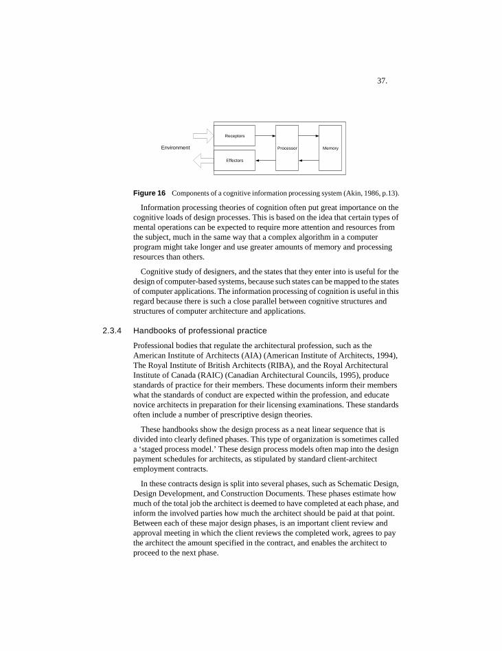
37.
Figure 16 Components of a cognitive information processing system (Akin, 1986, p.13).
Information processing theories of cognition often put great importance on the cognitive loads of design processes. This is based on the idea that certain types of mental operations can be expected to require more attention and resources from the subject, much in the same way that a complex algorithm in a computer program might take longer and use greater amounts of memory and processing resources than others.
Cognitive study of designers, and the states that they enter into is useful for the design of computer-based systems, because such states can be mapped to the states of computer applications. The information processing of cognition is useful in this regard because there is such a close parallel between cognitive structures and structures of computer architecture and applications.
2.3.4 Handbooks of professional practice
Professional bodies that regulate the architectural profession, such as the American Institute of Architects (AIA) (American Institute of Architects, 1994), The Royal Institute of British Architects (RIBA), and the Royal Architectural Institute of Canada (RAIC) (Canadian Architectural Councils, 1995), produce standards of practice for their members. These documents inform their members what the standards of conduct are expected within the profession, and educate novice architects in preparation for their licensing examinations. These standards often include a number of prescriptive design theories.
These handbooks show the design process as a neat linear sequence that is divided into clearly defined phases. This type of organization is sometimes called a ‘staged process model.’ These design process models often map into the design payment schedules for architects, as stipulated by standard client-architect employment contracts.
In these contracts design is split into several phases, such as Schematic Design, Design Development, and Construction Documents. These phases estimate how much of the total job the architect is deemed to have completed at each phase, and inform the involved parties how much the architect should be paid at that point. Between each of these major design phases, is an important client review and approval meeting in which the client reviews the completed work, agrees to pay the architect the amount specified in the contract, and enables the architect to proceed to the next phase.
Receptors
Processor
Effectors
MemoryEnvironment
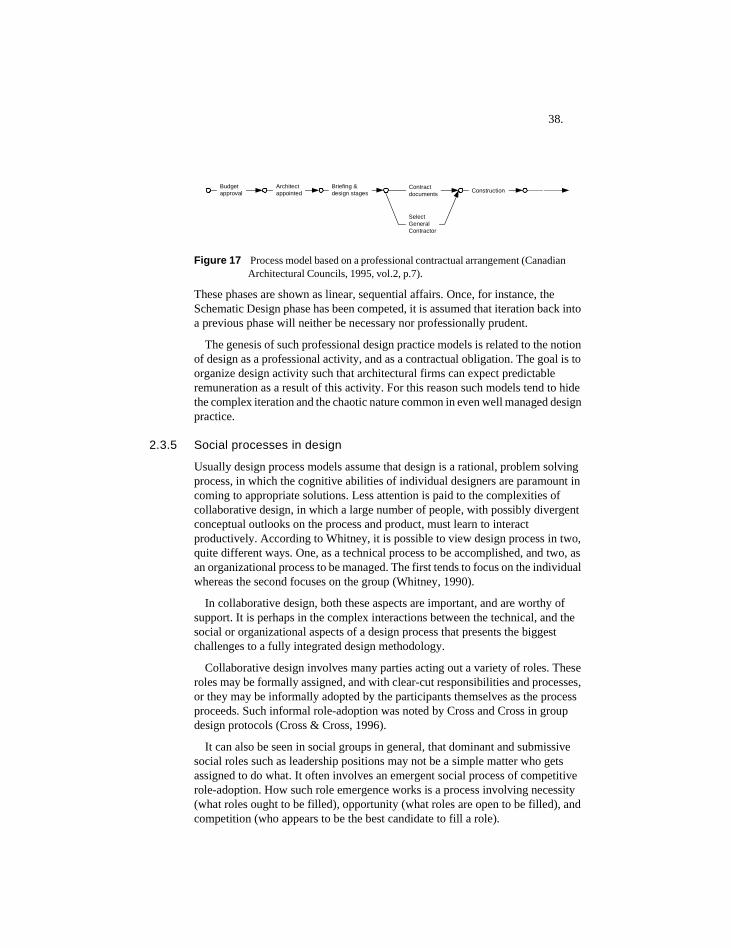
38.
Figure 17 Process model based on a professional contractual arrangement (Canadian Architectural Councils, 1995, vol.2, p.7).
These phases are shown as linear, sequential affairs. Once, for instance, the Schematic Design phase has been competed, it is assumed that iteration back into a previous phase will neither be necessary nor professionally prudent.
The genesis of such professional design practice models is related to the notion of design as a professional activity, and as a contractual obligation. The goal is to organize design activity such that architectural firms can expect predictable remuneration as a result of this activity. For this reason such models tend to hide the complex iteration and the chaotic nature common in even well managed design practice.
2.3.5 Social processes in design
Usually design process models assume that design is a rational, problem solving process, in which the cognitive abilities of individual designers are paramount in coming to appropriate solutions. Less attention is paid to the complexities of collaborative design, in which a large number of people, with possibly divergent conceptual outlooks on the process and product, must learn to interact productively. According to Whitney, it is possible to view design process in two, quite different ways. One, as a technical process to be accomplished, and two, as an organizational process to be managed. The first tends to focus on the individual whereas the second focuses on the group (Whitney, 1990).
In collaborative design, both these aspects are important, and are worthy of support. It is perhaps in the complex interactions between the technical, and the social or organizational aspects of a design process that presents the biggest challenges to a fully integrated design methodology.
Collaborative design involves many parties acting out a variety of roles. These roles may be formally assigned, and with clear-cut responsibilities and processes, or they may be informally adopted by the participants themselves as the process proceeds. Such informal role-adoption was noted by Cross and Cross in group design protocols (Cross & Cross, 1996).
It can also be seen in social groups in general, that dominant and submissive social roles such as leadership positions may not be a simple matter who gets assigned to do what. It often involves an emergent social process of competitive role-adoption. How such role emergence works is a process involving necessity (what roles ought to be filled), opportunity (what roles are open to be filled), and competition (who appears to be the best candidate to fill a role).
Architectappointed
Budgetapproval
Briefing &design stages
Contractdocuments
SelectGeneralContractor
Construction
39.
2.3.6 Coordination theory
Coordination science is a new discipline that has been developed to help explain and manage complex collaborative situations that tend to overwhelm existing process management theory and technique. Whitfield, Coates, Duffy, and Hills (2000), Klein (1998), and Malone and Crowston (1992) provide excellent overviews. Coordination of action is required, according to Klein (1998), when distributed activities, such as those found in collaborative design, are interdependent.
Malone and Crowston provide a good, concise definition of coordination: “the act of working together harmoniously” (1992). Malone and Crowston also provide a list of technical definitions others have proposed for the term. A useful discussion is provided by Jennings (1996) regarding the three main reasons why the actions of multiple agents need to be coordinated. 1. because there are dependencies between agents' actions, 2. because there is a need to meet global constraints, and 3. because no one individual has sufficient competence, resources, or information to solve the entire problem.
According to Klein (1998), the most fundamental aspect of support for coordination comes through communication. That is, it is inconceivable that in whatever design coordination regime, whether software-based or otherwise, that agents will be able to coordinate their work without actually communicating with one another. In hierarchical control situations, this communication may be indirect, through, for example, an agent's manager or controller, while in distributed cases it occurs directly between agents.
Jennings proposes that coordination is built upon four main structures: commitments, conventions, social conventions, and local reasoning capabilities. If an agent commits to performing a particular action, then, if circumstances do not change, it will endeavor to honor that pledge (Jennings, 1996). Non-performance of a commitment, made in a social setting, can entail social costs, which people sometimes go to extraordinary lengths to avoid. However, commitments are not irrevocable, since the circumstances that inspired them in the first often change. The longer the time between making a commitment, and the time that action is required, increases the likelihood that the commitment may need revision. From a distributed systems perspective, commitment by agents to a course of action adds a degree of certainty to future events. This is an important consideration in such systems, since due to their distributed nature they experience a great deal of uncertainty.
40.
2.3.6.1 Centrality of commitments and conventions hypothesis
Jennings offers a hypothesis that has the potential of providing structure and order within the domain of collaborative design. Jennings proposes the following (1996):
1. all coordination mechanisms can ultimately be reduced to commitments and their associated (social) conventions,
2. commitments are viewed as pledges to undertake a specified course of action, and
3. conventions provide a means of monitoring commitments in changing cir-cumstances.
The work of Terry Winograd incorporates well-known criticisms of the rationalist approach to design, cognition, and intelligence (Winograd & Flores, 1987). He emphasizes, like Schön (Schön, 1983) and Bucciarelli (Bucciarelli, 1994), the social processes required for groups to come to some common understanding. He sees the interactive nature of language use, such as described in speech act theory (Searle, 1991), to be a primary factor in such social processes.
2.3.6.2 'Plans-as-programs' vs. ‘plans-as-communications’
Agre and Chapman in their influential report “What are plans for?” distinguish between two uses for symbolic plans: one as ‘plans-as-programs’, and ‘plans-as-communications’ (Agre & Chapman, 1989).
Plans-as-programs are intended as algorithmic accounts of the steps to be followed in order to fulfill certain goals. This approach is consistent with the theories of an influential faction in cognitive science, which posits that following symbolic plans is necessary to enable rational, goal-directed activity. Plans-as-communication are seen as much more informal, linguistically based accounts of what should be done. They suggest that complex activity depends both on symbolic descriptive models, as well as real-time, situated improvisation. For the symbolic-modeling side of this vigorously debated issue see Vera and Simon (1993) while for the opposing, situated view see Clancey (1993).
According to Agre and Chapman, the plans-as-program approach suffers from the following problems: 1. it poses computationally intractable problems, 2. it is inadequate for a world characterized by unpredictable events such as the actions of other agents, 3. it requires that plans be too detailed, and 4. it fails to address the problem of relating the plan text to the concrete situation (Agre & Chapman, 1989).
Plans-as-programs are seen as being insufficiently flexible, in that appropriate real world activity depends on real-time adaptive responses to uncertainties. These uncertainties are difficult or impossible to predict in advance. How to deal with uncertainties and contingencies is especially important in the field of robotics. A central problem within robotics is how to design robots capable of negotiating real-world environments. One approach to this problem is the work of Brooks, in which non-deliberative, reactive interactions between robots and the
41.
environmental stimuli they might encounter is favored, instead of plan construction and plan following (Brooks, 1991).
In agreement with the position of Brooks, Agre and Chapman view the problem with the plan-as-program view is that it understands activity as a matter of problem solving and control, rather than one that involves fashioning real-time adaptive responses to constantly changing situations. Similar issues are relevant in the domain of design process support, in which adaptive, 'opportunistic' responses to complex, dynamic situations are also important. Yet, Agre and Chapman do not see plans-as-programs as necessarily ineffectual: in situations that have relatively static, well-defined semantics, and low levels of uncertainty, they can be very useful.
In contrast, the plan-as-communication approach sees plans as resources, among many other resources, which agents may choose to use or not to use, in the context of complex activities. Additional resources could be many things such as the opinions of others, clues from the environment, the contents of other plans, etc.
Here, the contents of a plan are not directly connected to a cognitive, perceptual, and motor system that depends on access to detailed plans in order to function at all—which is the case with plan-directed robots. Therefore, items in a plan have a much less central role to play than in the plans-as-program view, where plan contents are used not only to inform, but also to structure and to effect activity. The plans-as-communications approach assumes the existence of a general cognitive ability beyond that of plan construction and execution, and depends on an agent understanding the meaning of an item on a plan.
Plans-as-programs are useful in agents that inhabit simple, static environments in which the execution of relatively static symbolic plans is suitable. This assumes that there exists some agent who is capable of creating the plan in the first place, and that once created, the plan will not have to be re-planned at every step of its execution, due to unforeseen contingencies.
These criticisms are relevant to collaborative design where there is usually no one party that is capable of devising a plan that will enable all the activities of a design team to be structured. In addition, even if a plan did exist it is unclear how closely a design team would want or be capable of following it. Finally, due to the unpredictable nature of collaborative design, it is clear that any plan will have to be under constant revision, in order to cope with the changing circumstances, re-interpretations of requirements, and design opportunism common within design teams. Therefore, the plans-as-communications approach appears to be a more realistic model of how plans are actually used in collaborative design.
2.3.6.3 Recurrent social processes
Collaborative design involves both the search for solutions to artistic and technical problems, and also the specification and coordination of the recurrent social interactions encountered during a collaborative design process. These interactions involve many activities: the assembly of the collaborative team, the generation and communication of relevant ideas to other team members, the resolution of design conflicts—which seem to inevitably arise from most collaborative activity—and
42.
the negotiation required to assess whether a design proposal is an appropriate solution given a perceived set of design requirements. Within collaborative design all of these processes are seen as socially mediated ones, depending crucially on interpretation, negotiation, and the construction of meaning in a social context.
Collaborative design process should not be seen as a problem that can be viewed objectively, or one that exists independently, of the people who are asked to solve it. Rather, both architectural problems and design processes require interpretation. This interpretation must be communicated to others in the team, and various consensuses must be arrived at within the team for the design problem to be solved adequately, and to everyone’s satisfaction.
This socially mediated and constructed process however, is seen to be one that is greatly constrained by the patterns of social and technical interactions that design team participants bring to the table. The sources of such patterns of behavior are thought to be their previous experiences working in design teams, and by their experiences working in collaborative social situations in general. Since designers usually have similar experiences of doing design, this is expected to converge into recurrent social patterns of interaction.
This approach—that social behaviors such as collaborative design are both socially constructed by their participants while they occur, as well as constrained by the participants experiences performing related activities in the past—can be found in many domains, for instance, cognitive science (Varela, Thompson, & Rosch, 1991), theory of the collaborative use of language (Clark, 1996), and accounts of engineering design processes (Bucciarelli, 1994).
2.3.7 Design processes from a top-down perspective
Collaborative design has important top-down aspects that can structure both product and process. Top-down, or centralized process control can be derived from many factors, including:• Social and cultural factors: a strong personality or common culture that drives
teams to perform design in a certain way.• Technical factors: a focused expertise that has a strong effect on the design
direction.• Organizational factors: when the hierarchy of organizations is reflected in the
structure of a design product or process. • Financial factors: when the money flows from centrally controlled sources. • Contractual factors: when parties agree in a legally binding manner to submit to
some central authority.• Consensual factors: make parties commit themselves to an agreed course of
action.
From a product perspective, certain global aspects of a design product are normally required to facilitate management of collaborative design, such as the total cost, or the quantities of materials used in a proposed product model.
However, centralized process control and product representation do have their limitations. As Klein notes (1998), centralized control requires that a single person
43.
or software system have some deep understanding of the entire design. As noted above, this is not so difficult for small projects, but becomes impractical for large ones, with large dependency networks.
It is especially difficult for projects that require inputs from multi-disciplinary teams who often speak different ‘languages.’ In order to understand and participate in the coordination of various contributions, a central controlling party therefore must be ‘multi-lingual.’ This is a tall order if the composition of a design team includes a wide variety of experts, each speaking very specialized languages. Here, a practical expectation is that outsiders will only be able to understand a small subset of what is what is important within such domains of expertise. It might be feasible to standardize languages such that everyone speaks the same one, but this, as Stouffs and Krishnamurti (2001) note, is likely to be at the expense of expressiveness and flexibility.
In theory then, centralized control may become impractical once design projects attain a certain size and complexity. If centralized control is impractical in certain situations, which may not be that uncommon, then forms of distributed, localized control may become necessary.
2.3.8 Design processes from a bottom-up perspective
From a bottom-up perspective, collaborative design can be modeled as a complex system. Complex systems research addresses at a fundamental level, the behaviors of interdependent entities (Klein et al., 2001). Complex systems typically have no central controller, and the global behaviors they exhibit, emerge because of local concurrent actions. Biological systems, such as ecosystems and organisms, are perhaps the most commonly presented examples of complex systems (Resnick, 1994). Concepts from complex system theory can also be applied to social systems, in which individuals forming social groups are seen as interdependent entities (Axelrod, 1997). Complex systems can be inorganic, or non-biological, as well.
According to Klein (2001), designers, as well as design issues, can be modeled as 'nodes' in dependency networks. In such a view, completing a collaborative design process, involves designers attempting to maximize the value of a (hypothetical) global utility function. This usually takes place in the context of extremely large design spaces. One difficulty in collaborative design is knowing what the global utility of a proposed design might be, prior to actually building a completed artifact. Even with a completed artifact, interpretations regarding the global utility of a design can vary.
Klein notes that the problem with collaborative design in general, is that the networks that most realistically model how collaborative design is done in practice, and ought to be done in practice, are also the ones that display the most complicated behaviors.
Dependency networks can have a variety of dynamics including non-linear, asymmetric, and non-convergent ones. Linear networks are those with single attractors. This situation is helpful in a collaborative design process, since it means, despite complex interdependencies and interactions between nodes, design
44.
solutions converge to a single point. This point corresponds to a global optimum. Klein notes that only routine design processes have been successfully modeled as linear networks.
Networks that exhibit non-linear network dynamics complicate the situation considerably, in that their utility function can have many peaks instead of single ones. These peaks represent local optima. Since local optima are often surrounded by valleys, search for global optima is made much more difficult. This applies to both software-supported design processes, as well as manual ones.
In collaborative design, this situation means that incremental improvements to a given design configuration, such as product models as they currently appear, may improve the designs, but will not necessarily lead to global optima. To discover global optima, design teams may need to consider radically different configurations of design components. This is often an expensive and risky proposition. The history of product development often shows such dramatic re-configurations, in addition to incremental improvement of existing configurations (Bijker, 1995).
Hogg notes the prevalence of non-linear interactions in distributed systems (1998). He states that such systems can display a wide range of behaviors including stable equilibria, continual oscillations, and chaos. Chaos is considered a destructive aspect of distributed systems in that it introduces global unpredictability into the system. Hogg proposes that simple reward mechanisms, based on the assessed performance of software-based agents, can help eliminate such chaos.
Within the Distributed Artificial Intelligence (DAI) community, the strategy of distributing control, data, as well as knowledge sources, is now widely supported (Whitfield et al., 2000). Such an approach has been shown to have several advantages, including the reduction of performance bottlenecks, the increase in reliability, and the soft, rather than steep or complete degradation of performance when systems are under stress.
Distributing control and data can also have disadvantages according to Jennings (Jennings, 1996), in that 1. each agent only has a partial and imprecise perspective, 2. there is increased uncertainty about each agent's actions, 3. it is more difficult to attain global behavior, and 4. the dynamics of such systems become extremely complex.
However, distributed control when placed in a design context is a concept that may not have much appeal to designers. Designers are usually trained to view their primary job description as ‘controllers of design processes.’ The traditional expectation is that in order for a designed product to have some kind of aesthetic or functional coherence and integrity, a single cognitive entity such as a designer, must conceive and coordinate the design in its entirety. For smaller design problems, this is quite possible. For more complex problems, or for those that take place over an extended period, it becomes more difficult. For example, the centers of old European cities, or vernacular settlements such as Italian hill towns, may take several hundred years to be designed. Their design processes involve the accumulation of contributions from many designers. Despite the distributed nature
45.
of their conception and construction, such designed products are considered by many to be the height of western architectural achievement. The reason that they are seen to exude such charm seems related to how each local contribution is coordinated with that of its neighbors, such that the whole exhibits an ‘organic’ quality. Such adaptable and locally coordinated design processes are quite difficult to emulate using centrally controlled processes.
Complex collaborative design processes can indeed be centrally controlled. However, once design projects get to a certain degree of complexity, central control introduces limitations into the collaborative process. This is especially true if this complexity is combined with designers' attempts to be innovative and creative, such that new global design optima might be discovered.
A similar argument could be made for the desirability of market-based rather than centrally planned economies. Once the number of economic transactions reaches a certain level, the ability of any central authority to allocate resources effectively, becomes compromised. Thereafter, more distributed, emergent, ‘invisible hand’ approaches become necessary.
2.4 Peer-to-peer software
2.4.1 Introduction
Peer-to-peer (P2P) involves having computers on a network—peers—acting as both suppliers, as well as consumers of information. P2P does not constitute a new idea—it has been around as long as computing itself.
The idea behind P2P technology is to enable the sharing of information between distributed peers, without the necessity of first setting up a centralized system to do this. One promising approach to the P2P is the JXTA initiative by Sun Microsystems (Sun Microsystems, 2002). This standardized, open-source initiative provides a protocol, with language bindings for several languages that enables for the easy design and implementation of secure P2P applications.
2.4.2 What does P2P mean for computing?
The supporters of P2P list its many apparent advantages (Oaks, Traversat, & Gong, 2002) (Peer-to-Peer Working Group, 2002):• Scalability: the ability of P2P applications to increase their performance as more
users are added, rather than to decrease it.• Robustness and fault tolerance: the ability of P2P to degrade gracefully when
network connections, or computing resources in general become unavailable or corrupted.
• Dynamic behavior: the ability to handle and dynamically adjust to the presence or absence of specific computer resources.
• Spontaneity: the ability of applications to respond to changes brought to computer systems by inputs from new peers and new computing resources,
46.
without having to preconceive these changes or to do special work to handle them when they do occur.
• Self-organization: the ability of people working on a P2P network to organize into specific peer groups of their own design, without the requirement of any centralized interventions.
2.4.3 JXTA by Sun Microsystems
JXTA (a term meaning ‘juxtapose’) is a standardized, open-source initiative that provides a protocol, with language bindings for several languages, that enables the design and implementation of secure P2P applications. JXTA is based on open-source, standards-based protocol specification, and can be implemented in Java or any other languages (Oaks et al., 2002). JXTA also provides a generic infrastructure to deploy P2P services and applications (Gong, 2001). JXTA is built out of five key abstractions: uniform peer ID addressing, peergroups, advertisements, resolvers, and pipes (Oaks et al., 2002).
2.4.3.1 Peers
Peers are the basic unit of JXTA. Peers can be both the consumers as well as producers of services found on a JXTA network. As defined in the JXTA specification, a peer is a device that implements one or more of the JXTA protocols. From the user’s point of view, a peer is the user of a P2P application. One of the basic ideas of P2P is to reduce the barriers to communication by flattening communication hierarchies and making everyone a potential 'peer'.
2.4.3.2 Peergroups
Peergroups in P2P systems act as virtual social spaces in which peers can interact and exchange information. In the JXTA protocol, the technical definition of a peergroup is a collection of peers that have agreed upon a common set of services (Sun Microsystems, 2002). It is up to cooperating peers to define groups, join groups, and leave groups (Oaks et al., 2002, p.16).
The purpose of peergroups is to:
1. Define a set of services and resources
For instance, the ‘dpmNet’ peergroup created by the application in this thesis has specialized services that enable peers to vote on the state of design entities. Other peergroups could have other services, such as access to secure information sources, or ways to interact with their fellow peers.
2. Provide a secure region
Peers must be members of the same peergroup in order to share information. Peergroups can be designed with strict membership requirements. Therefore, peergroups can be designed such that they are suitable to share sensitive information if they are configured to enable only qualified peers to join the peergroup. By default, all peers become members of a ‘world’ peergroup when
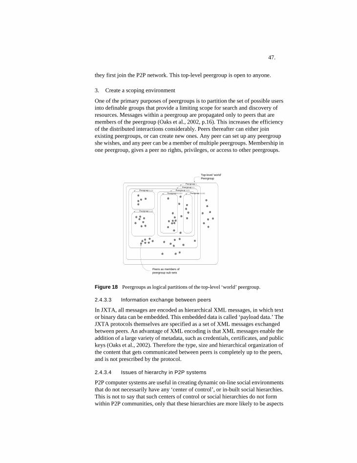
47.
they first join the P2P network. This top-level peergroup is open to anyone.
3. Create a scoping environment
One of the primary purposes of peergroups is to partition the set of possible users into definable groups that provide a limiting scope for search and discovery of resources. Messages within a peergroup are propagated only to peers that are members of the peergroup (Oaks et al., 2002, p.16). This increases the efficiency of the distributed interactions considerably. Peers thereafter can either join existing peergroups, or can create new ones. Any peer can set up any peergroup she wishes, and any peer can be a member of multiple peergroups. Membership in one peergroup, gives a peer no rights, privileges, or access to other peergroups.
Figure 18 Peergroups as logical partitions of the top-level ‘world’ peergroup.
2.4.3.3 Information exchange between peers
In JXTA, all messages are encoded as hierarchical XML messages, in which text or binary data can be embedded. This embedded data is called ‘payload data.’ The JXTA protocols themselves are specified as a set of XML messages exchanged between peers. An advantage of XML encoding is that XML messages enable the addition of a large variety of metadata, such as credentials, certificates, and public keys (Oaks et al., 2002). Therefore the type, size and hierarchical organization of the content that gets communicated between peers is completely up to the peers, and is not prescribed by the protocol.
2.4.3.4 Issues of hierarchy in P2P systems
P2P computer systems are useful in creating dynamic on-line social environments that do not necessarily have any ‘center of control’, or in-built social hierarchies. This is not to say that such centers of control or social hierarchies do not form within P2P communities, only that these hierarchies are more likely to be aspects
Peergroup 1Peergroup 1.1
Peergroup 1.1.1
Peergroup 1.1.2
Peergroup 1.1.3
Peergroup 1.1.3.1 Peergroup 1.1.3.1
Peers as members ofpeergroup sub-sets
Top-level 'world'Peergroup
48.
of the social interactions themselves, rather than a reflection of the design of software systems that support these interactions. This lack of inherent hierarchy is clearly a useful feature for domains that depend on the easy transfer of information between ordinary users, and on the flexible and dynamic construction of social groups online.
P2P systems appear to have promise within collaborative design support, since collaborative design requires the dynamic construction and re-construction of various social environments and groups, such as design teams and sub-groups within design teams. The concept of peergroup enables such social construction to take place in an on-line, geographically distributed fashion.
49.
2.5 Wisdom of crowdsIn his book The Wisdom of Crowds: Why the Many are Smarter than the Few, James Surowiecki (2004) explores the decision-making capability of decentralized, distributed groups of people. He writes “under the right circumstances, groups are remarkably intelligent, and are often smarter than the smartest people in them. Groups do not need to be dominated by exceptionally intelligent people in order to be smart.” (p.xiii)
Surowiecki focuses on three types of problems:
1. Cognition problems: problems involving conceptualization of appropriate problems and solutions alternatives. According to Surowiecki, these are prob-lems that have or will have definitive solutions.
2. Coordination problems: problems involving adapting their behaviors to the behaviors of others, so that people can work productively together.
3. Cooperation problems: these involve getting people to work together on com-mon projects that involve the self-interest of multiple parties.
It is clear that collaborative design also involves these three types of problems: designers must solve problems involving the conceptualization of alternatives to complex problems, they must adapt their behavior to the behaviors of others such that some kind of collaborative order is created, and they must cooperate with their peers, such that self-interested parties manage to work together.
His argument is mainly supported from finding from psychological research and the world of business and finance, and he sees his basic message as somewhat counter-intuitive. He does emphasize that groups are not always smarter, just that in some specific circumstances, they can become smarter. The conditions that must be present for ‘wise crowds’ to result, are the following:
1. Diversity of opinion: what people know and believe, or the conceptual and cognitive perspective they have on events of common interest, is different to that of others.
2. Independence: people are in a position to think about events in a way not un-duly influenced by the opinions of others.
3. Decentralization: people have access to local or specialized knowledge.4. Aggregation: A mechanism exists to covert distributed private judgments into
a collective decision—which may not correspond to the opinion of any one contributor to the decision (Surowiecki, 2004, p.10).
As a mathematical explanation of how this mechanism works: At heart, the answer rests on a mathematical truism, If you ask a large enough group of diverse, independent people to make a prediction or es-timate a probability, and then average those estimates, the errors each of them makes in coming up with an answer will cancel themselves out. Each person’s guess, you might say, has two components: information and error. Subtract the error, and you’re left with the information (p.10).
50.
The first three conditions are quite similar and distinguish groups of people in which members are in a position to think for themselves and whose opinions are valued. Such is the case with the normal collaborative design team, members of a design team are chosen normally for their diversity of opinion, and their specialized knowledge. Structural engineers are seen as valuable and necessary colleagues for architects precisely because engineers’ professional training and experiences enable them to propose structural solutions and solve problems that architects are not specialized to perform.
Being on a team, however may work against this independence of thought. To become part of a team implies that a certain degree of individual autonomy is lost in order to conform to the social norms that the team creates. Working together with people, as a design team implies must occur, by definition reduces the independence of each individual member.
The fourth condition, however, is quite different than the first three in that it involves a technical mechanism rather than a social structure. The first three conditions are commonly found when people are in a position to view distributed events, or acquire specialized knowledge, and therefore perspectives. As Surowiecki points out, teams often get the first three points right, but not the final one. Teams often allow intelligent people to come with sufficient resources to make ‘wise’ collective decisions, but do not provide a mechanism for translating this diversity into specific decisions that takes into account everyone’s contribution.
The three most common aggregation mechanisms are:
1. Voting, or rating systems: found in democratic elections, the page-ranking al-gorithm of Google, or self-organizing web sites in which highly-rated content can ‘bubble to the top’ (Hafner, 2001).
2. Markets, in which buyers and sellers coordinate their behavior. This is found in financial markets of all kinds including stock and commodity markets, and also in decision markets such as the Iowa Electronic Markets (Iowa Electronic Markets, 2004).
3. Imitation and influence systems: in which people base their behavior by imi-tating what others do. This can be found in fads, stylistic movements, trends, fashions, and riots. Such behaviors can often turn out badly since each mem-ber loses independence of decision-making, and may do things that if they were independently considered, the member would not have done.
2.5.1 Relevance to collaborative design
Collaborative design exhibits all three types of problems identified above: cognitive, coordination, and cooperation. Design teams come in various sizes and often only have a small pool of ‘voters.’ The smaller is the pool from which information can come, the less is the effect of the ‘wisdom on the crowd.’ Collective wisdom appears to depend on a large sample size. There is also tension between independence and conformity: In collaborative design teams, members are both expected to work independently and provide ideas and information
51.
informed by specialized knowledge. In contrast, designers are also expected to conform to the design team’s objectives and behaviors, and learn to get along with others on the team. This tension between wanting to be independent of the group, as well as cognizant and respectful of the team’s emerging social norms, appears to be an essential aspect of collaborative design. It reflects the fact that designers must in the end produce a conceptually, unified artifact informed by the aggregated contributions of agents with varying degrees of conceptual and social independence.
In design teams, the lack of technical aggregation mechanisms is not necessarily a problem. In normal practice, design teams do not have access to technical intervention of aggregating mechanisms such as elections, rating systems, or markets. Decisions are made based on available alternatives and on the intellectual resources of the team. This means that it is conceivable for good decisions to be made, despite the lack of technical aggregation systems, if contributions provided by individuals are taken into account when making final decisions.
In summary, Surowiecki writes:Decentralization’s great strength is that it encourages independence and specialization on the one hand while still allowing people to coordinate their activities and solve difficult problems on the other. Decentraliza-tion’s great weakness is that there’s no guarantee that valuable informa-tion, which is uncovered in one part of the system, will find its way through the rest of the system (2004, p.71).
2.6 Centralized and distributed systems comparedInformation systems that support collaborative design, can be designed either as centralized or decentralized systems. Up to now the tendency has been to build centralized systems, such as those that employ client-server architectures.
P2P are seen as one end of a spectrum of available network topologies, in which completely centralized systems are at the other end. Here, the author attempts to analyze the implications of the two ends of the spectrum, rather than spend time discussing the myriad shades of grey in between. It seems likely that the most profitable approach in design systems will be to make hybrid systems that take advantage of the inherent advantages of both the distributed and centralized approaches.
2.6.1 Factors that promote the centralized approach to collaborative design
2.6.1.1 The suitability of centralized architectures in development of centralized, integrated product models
As it is usually a single unified artifact that is the intended result of a collaborative design process, it seems to make sense to attempt to make unified design representations from the beginning stages of design. Since the goal is to produce a single unified model, it makes sense to keep this model in one, centralized location. Integrated product models have the potential advantage of having a high level of internal consistency and rationality in their design. Models in which all
52.
design description information resides in one location, can be, for instance, very convenient when checking for completeness and consistency of design product models (Flemming & Woodbury, 1995).
2.6.1.2 An approach towards collaborative design that favors rationally planned processes
The dominant design paradigm within the computer-aided design community has been one inspired by the promise of rational and scientific reasoning and planning in solving complex problems. One goal of technical reasoning is to provide a supportable rationale for design decisions, such that the overt subjectivity and biases of individuals are avoided. When design problems are seen primarily as ones that can be solved by application of technical or scientific reason, then it becomes important that the actors involved in a design process have technical or scientific reasoning, and problem solving skills. A rational, defensible design path then should be clear to most of the participants engaged in the design process, provided they are competent thinkers and professionals. Therefore, with a rational approach, specific actors, and their attendant biases, are seen as less important, and it becomes more acceptable that a reasoning engine that orders a complex design process, be located in a single, centralized location.
2.6.1.3 The lack of credible alternatives to centralized systems, such as P2P
Popularity of P2P depends on both a conceptual shift, such that they can be seen to useful in theory, as well as a technological shift, such that P2P computer systems become practical to develop. P2P in its modern embodiment is a relatively new idea that has failed to achieve a ‘critical mass’ of popularity among users, researchers and developers—except in domains such as on-line file sharing or instant messaging (IM). Until recently, there has been a lack of reliable P2P technology and of suitable P2P application development frameworks. These frameworks enable a standards-based, non-proprietary approach for P2P application development, which is seen as an important factor in popularizing P2P theory and applications. It is the author’s opinion that the appearance of JXTA by Sun has changed this situation, and that there are now few technical impediments to discourage the growth of P2P. However, there appears to some legal ones, which could impede development of P2P systems, especially in the short term.
2.6.1.4 Accessibility of unified design representations
Having a centralized representation means that this representation is available without any additional effort on the part of the administrators of this data. Therefore, the documentation process does not require the burden of a process of assembly of documents, from their variety of authors, such as from the various consultants involved in a collaborative design process. Such an assembly process can sometimes be prohibitively expensive. This means, for instance, that historical records of building projects can be maintained much more easily when there are integrated and centralized design representations.
53.
2.6.1.5 Rational design of information infrastructures
Despite the fact that various design agents may have different conceptualizations of design data and of the design process, there remains the fact that information infrastructure design, such as database design, can be helped enormously when people skilled in this domain design it. Distributed logic may enable design participants in theory to express anything they wish to express. However, this kind of freedom may not be necessary in many cases. Simple logical structures may satisfy most, if not all of the design participants.
2.6.1.6 Usefulness in routine design processes
In the context of design systems, the intended degree of innovation in the design process is an important factor. In routine design processes—ones in which the participants may have long experience, working within conceptual frameworks that are unlikely to change dramatically—centralized systems can obviously provide useful support for designers. In routine design, the issue of design freedom is not normally relevant. Preconceived goals in such design situations are not really unwelcome constraints, but rather an essential feature of this type of design.
2.6.2 Disadvantages of centralized systems
2.6.2.1 Covert conceptual prescriptions
The process of conceptual design usually involves coming to a consensus with your design collaborators as to what an appropriate conceptual organization for the project should be. In centralized design systems, this type of consensual pre-design work is often contained implicitly within the design of the computer system itself. In some cases this pre-definition of the semantics of design objects of interest, could conceivably have an unwelcome and constraining effect on the types of solutions that could result from the use of such a system. The same could be true of P2P systems, although it is expected that the type of covert prescriptions might be of a different type.
2.6.2.2 Location of proprietary data
Centralized systems usually assume that participating designers in the collaborative design process are willing, or able, to submit their design contributions to a party, or a computer-based system, that maintains a central data store or representation. In order to conform to a central representation, data translation and formatting work may be involved on the part of individual contributors. Some designers and consultants may have a proprietary interest in not allowing their specialized design representations to reside in any location other than their own private and secure databases. They may only share a subset of their data such that design collaboration is possible, without offering the full richness of the data, they may use internally within their own organizations (Snyder, 1998).
2.6.2.3 Necessity of 'up-front' work
Centralized architectures tend to depend on substantial quantities of 'up-front' work to build suitable information infrastructures. Centralized systems, by
54.
definition, require the people they might affect—their 'stake-holders'—get together and work out what would be an appropriate, supportive system. Such consensus-building work takes much effort, and ideas what constitutes an appropriate system may vary widely, even among skilled professionals acting in good faith. Work on computer-based information infrastructure is usually work of a technical nature that designers in many domains may be unqualified to perform, without support from specialized information professionals. Such work, especially with centralized systems, tends to require making prescriptive and predictive assumptions about the nature of the information to be exchanged, as well as the composition and organizational hierarchy of the design team. Such aspects of collaborative practice may become clear to the design team only once a design process is well established.
This is commonly recognized problem with design, especially in early design support systems: how to support a design process without unduly shaping it to conform to a computer system designer’s preconceptions. In order for a computer system to be useful in supporting design, the system must exist. The same is true for both centralized or distributed systems. What is important is the effort required to get useful systems working, and whether these systems support or unduly shape the nature of a design process. It appears that centralized systems tend to be weak in both these respects. However, with the absence of complex P2P design systems to compare them to, it is difficult to determine at this time whether P2P systems would be any better.
2.6.3 Advantages of distributed systems
2.6.3.1 A better model of data sharing?
In collaborative design, similar to what happens in P2P systems, individual agents often assume the roles of information providers as well as information consumers. The fact that P2P systems enable this process to occur transparently is seen as a major advantage of this technology.
2.6.3.2 Distributed control
Decentralized systems do not require that one party assumes a position of control over the work of others. This may or may not be the organizational approach that is appropriate for a specific design project. However, recent managerial trends that emphasize the advantages of flatter, leaner management hierarchies in developing more agile and productive organizations, suggest it is a trend growing in popularity.
In complex, collaborative design projects, where the input of specialized design experts may be crucial to finding acceptable solutions, hierarchical control of such experts may not be, for instance, politically appropriate. Instead, complex systems rely on independent or autonomous agents interacting with each other in plausible ways, generally without access to global knowledge. Some would argue that this approach better simulates the behavior of real designers as they perform their jobs—especially in complex, non-routine design situations.
55.
2.6.3.3 Chance of creative emergence
Decentralized systems work by enabling independent agents to interact in a manner that does not rely on pre-articulated or pre-conceived goals. In complex systems research, of which design of decentralized systems is a part, mechanisms of self-organization have been used to explain behaviors and constructions that appear to have resulted from hierarchically controlled, top-down processes, but in fact were not. In nature, ant colonies are prime examples of such a ‘design without designers’ phenomenon (Gordon, 1999).
2.6.3.4 No requirement for 'global' knowledge
Decentralized systems do not require a top-level party who is responsible for acquiring and maintaining 'global knowledge' within the context of what may be a dynamic, distributed, and highly interactive process. In the complex systems literature, the idea of global knowledge is questioned on practical as well as on theoretical grounds. In practice, it is often difficult for any one party to actually have sufficient insight, and objectivity to acquire such knowledge. What individual design agents 'know' tends to be influenced by their specific educational and professional backgrounds. Usually this diversity of conceptual outlooks is considered a positive feature of multi-disciplinary design teams. In theory, the basic idea that there exists global knowledge that is qualitatively more reliable or objective than the subjective knowledge that any single agent might acquire is also questioned.
2.6.3.5 Multiple knowledge sources rather than singular ones
Designers of P2P applications tend to view on-line resources as something that increase in quality with the increased diversity of these resources. For instance, if a user is on the hunt for specific music files by a particular artist, it is probably preferable to him if there are a variety of these types of files available for him to download. In this situation, a little bit of data redundancy is also not a bad thing. With diversity of data resources, of course there is the possibility that the quality of some of these resources may be inadequate.
2.6.4 Disadvantages of distributed systems
2.6.4.1 Lack of a central representation
The most salient feature of distributed systems is that their control and data are distributed. To maintain data integrity and consistency in distributed environments is usually much more difficult, than in centralized situations (Ferber, 1999). Since construction of centralized data models is often seen to be an important aspect of collaborative design practice, it appears that P2P is best suited for tasks other than the development of consistent and logical product representations.
2.6.4.2 Lack of central control
As described above, distributed systems suffer from the locality and limited visibility of each agent’s perspective.
56.
2.6.4.3 Possibility of behavioral chaos
Distributed systems since they lack central control, often exhibit non-linear interactions, as noted by Hogg (1998). Obviously, in collaborative design, the goal is usually to avoid such chaos.
2.6.5 Conclusions regarding centralization and decentralization
Situations that appear to favor the centralized approach to design are ones where one party assumes a central, authoritative role. This, of course, happens frequently in collaborative design. When design processes and the conceptual organization of product models are well understood, and are unlikely to evolve significantly, this suggests that local knowledge will be of less importance to a design process. When design collaborators understand appropriate roles they should assume, rather than having these roles defined dynamically within a design process, and when there is a requirement for complete data reliability and coherence, this tends to favor centralized design process approaches, in which designers usually have access to standardized and centralized data models.
Situations that favor the decentralized approach are ones in which the intention of the design team is to design in a highly innovative fashion, or when the design problem presents great conceptual or technical challenges. In such cases suitable, time-tested design approaches may not be available and team members may have little conclusive knowledge about their current design problem, and may lack experience working together as a design team.
2.7 Related work: design support and coordination systems
2.7.1 Adaptive workflow
Adaptive workflow involves a similar approach to that presented in this thesis. Workflow applications are a popular type of software for which there are many vendors, developers, and academic researchers (Workflow Management Coalition, 2004). The importance of workflow lies in its centrality to many business processes: how to inform people about what to do while they perform their job, in a context-sensitive manner.
In the 1990s workflow was often used as part of a business process reengineering exercise to automate ‘reengineered’ business processes. The emphasis was on technology, i.e. applications and systems, with less thought towards human interaction within the process and, as a result, workflow developed a poor reputation. However, with the ability for business processes to be modeled and monitored in real time, and for those processes to be more easily changed in response to volatile market trends and technology, interest is again growing in business process man-agement (Prior, 2004, p.17).
Workflow management of processes requires a process definition tool, a process execution engine, user and application interfaces to access and action work requests, monitoring and management tools, and reporting
57.
capabilities... Process modeling tools allow business users to coordinate business activities, people and applications, and to model routing of work requests within a process and across processes (Prior, 2004, p.20-21).
The term Workflow Management actually refers to the logistics of busi-ness processes. Workflow management does not focus on what informa-tion is being passed in a business process, but more on the control of the activity chain that is necessary to execute the business process (Aalst et al., 1999, p.37).
Like coordination of work of any type workflow has top-down and bottom-up control aspects. Some types of enterprise are inherently top-down oriented, while others are more bottom-up. Most, such as collaborative design, have a combination of the two.
In business, as in design, changes to processes are common and workflow management systems must be able to adapt to these changes, in an intelligence way. Adaptive workflow aims at providing process support like normal workflow systems do, but in such a way that the system is able to deal with certain types of changes (Aalst et al., 1999, p.36).
Change is seen an inevitable result of technological advances, changes in business environments, new laws governing business, new market requirements, or simply, unanticipated situations that require ad-hoc responses. These types of ad-hoc changes are referred to in the workflow literature as ‘exceptions.’
Business processes such as those addressed in workflow modeling, usually have a top-down emphasis. In business especially, employees expect to be told what to do in many situations. In management, the job of a manager is to manage. This job often entails definition of effective work processes that can benefit both the enterprise’s customers as well its employees. This inherent top-down nature of business management greatly affects the design of workflow systems meant for this domain.
2.7.2 Action workflow approach to process coordination
The design of the groupware application the ‘Coordinator’ is based on a theory of ‘language as social action’ (Flores, Graves, Hartfield, & Winograd, 1992; Medina-Mora, Winograd, Flores, & Flores, 1992). In its current commercial version, it comprises a suite of workflow tools called ActionWorks:
After years of studying human interaction, Action Technologies, Inc.'s founders, Terry Winograd, Ph.D. (Stanford) and Fernando Flores, Ph.D. (UC Berkeley), mapped every state and act in which people can work to-gether. Based on exhaustive research, they developed the closed-loop Business Interaction Model (set forth in their 1983 book, Understanding Computers and Cognition) (Winograd & Flores, 1987) that is at the heart of ActionWorks Business Process Management software...The solution coordinates interactions between an individual or group making a request (the Customer) and the individual or group who is the recipient of that request (the Performer) in four phases:
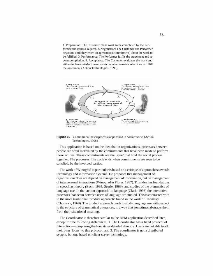
58.
1. Preparation: The Customer plans work to be completed by the Per-former and issues a request. 2. Negotiation: The Customer and Performer negotiate until they reach an agreement (commitment) about the work to be fulfilled. 3. Performance: The Performer fulfils the agreement and re-ports completion. 4. Acceptance: The Customer evaluates the work and either declares satisfaction or points out what remains to be done to fulfill the agreement (Action Technologies, 1998).
Figure 19 Commitment-based process loops found in ActionWorks (Action Technologies, 1998).
This application is based on the idea that in organizations, processes between people are often motivated by the commitments that have been made to perform these actions. These commitments are the ‘glue’ that hold the social process together. The processes’ life cycle ends when commitments are seen to be satisfied, by the involved parties.
The work of Winograd in particular is based on a critique of approaches towards technology and information systems. He proposes that management of organizations does not depend on management of information, but on management of interpersonal interactions (Winograd & Flores, 1987). This idea has foundations in speech act theory (Bach, 1995; Searle, 1969), and studies of the pragmatics of language use. In the ‘action approach’ to language (Clark, 1996) the interactive processes that occur between users of language are studied. This is contrasted with to the more traditional ‘product approach’ found in the work of Chomsky (Chomsky, 1969). The product approach tends to study language use with respect to the structure of grammatical utterances, in a way that sometimes abstracts them from their situational meaning.
The Coordinator is therefore similar to the DPM application described later, except for the following differences: 1. The Coordinator has a fixed protocol of interaction—comprising the four states detailed above. 2. Users are not able to add their own ‘loops’ to this protocol, and 3. The coordinator is not a distributed system, but one based on client-server technology.
59.
2.7.3 Thesis by Tay-Sheng Jeng
Tay-Sheng Jeng’s Ph.D. thesis: ‘Design Coordination Modeling: A Distributed Computer Environment for Managing Design Activities’ (Jeng, 1998) has similar goals to this thesis. His goal is “to develop an effective multi-user computer environment that supports design collaboration.”
He does this through proposing new representations for design process capable of reasoning about design process, managing dependencies between activities, and supporting dynamic coordination protocols for interaction. His emphasis is on management of remote collaboration, and distributed coordination, under a knowledge-based approach. The software developed is implemented using a three-tier approach with application interface, model server, and server database components.
The research sees visibility of coordination logic to be an important goal. A design coordination model (DCM) that takes a rules-based approach that attempts to ‘capture all meaningful process semantics used by designers to effectively realize work.’ (p.2)
The thesis focuses on the coordination level of design-related processes. He states that an important aspect of coordination is to bridge the gap between high-level project scheduling, and actual design operations (p.5). The process of design is seen as an activity in which tasks are articulated, and these tasks are composed or decomposed into task hierarchies. Therefore, he sees design management as fundamentally a top-down process in which a central authority assigns tasks for others, rather than a self-organizing activity between peers. His software prototype is called Design Back Office, which is described as a “distributed and persistent object system focusing in the design of computer environments supporting, managing, and controlling activities.” (p.70)
This work emphasizes coordination of design activities in a general way. How it differs from this thesis is its assumption that a top-down process should always be present to define and articulate design processes, rather than enabling bottom-up processes to also perform these functions.
2.7.4 Peer-to-peer projects in JXTAJXTA technology is a set of open protocols that allow any connected de-vice on the network ranging from cell phones and wireless PDAs to PCs and servers to communicate and collaborate in a P2P manner. JXTA peers create a virtual network where any peer can interact with other peers and resources directly even when some of the peers and resources are behind firewalls and NATs, or are on different network transports (JXTA, 2004).
There are many developments and research projects, in various stages of completion, under the JXTA umbrella. At the moment there appear to be no JXTA-based P2P applications under development that specifically address the design domain, nor ones that attempt to create structured role-based interactions, as described in this thesis. The examples below though give one a flavor of
60.
applications that the JXTA community are working on, and which do have some relevance to the current research.
2.7.4.1 Jxcube: Jxta eXtreme Cube - Fully Distributed Collaboration Platform
JXCube is a fully distributed collaborative application that enables users to collaborate, using various functions such as chat, messenger, file shar-ing or schedule management. It adopts a group-based communication style. Once a user joins in the group, the group space will be given. Each collaborative function added into JXCube is deployed to that group space. Features: 1. No explicit servers are needed. 2. collaborative func-tions can be added in plug-in form. 3. users can use same id on different machines (clone peer). 4. user can check other user's presence in real time. 5. support for auto configuration. 6. provide for the mediation ser-vice that mediate synchronization, consistency, sequencing, delay differ-ences (Jxcube, 2004).
2.7.4.2 P2pconference: A tool to conduct remote, text-based conferences
P2PConference is a tool developed using the Java binding of the JXTA P2P platform. It is based on an existing project, eWorkshop, from Ce-BASE. While it uses a web-based, chat application, eWorkshop is struc-tured to accommodate the needs of a workshop without becoming an un-constrained, on-line chat discussion. Goal: The original project's main idea is to develop a simple, web-based, collaboration tool to organize and conduct remote, text-based workshops, in order to synthesize knowledge from a group of invited experts. Assuming that direct, face-to-face dis-cussion cannot be totally avoided or replaced by the remote, text-based one, eWorkshop proved it can be effectively used to reduce the number of real meetings (and the economic costs they imply) by running several eWorkshops and, eventually, one or more unavoidable, real workshops (P2pconference, 2004).
2.7.4.3 AngeloPeerRendezvous: p2p-based software for intra-enterprise communication
A complete p2p based software for intra-enterprise communication. The motivation for doing this project is that companies disallow/discourage the use of instant messengers like MSN and Yahoo and though there exist custom made software for intra enterprise communication, they are ex-tremely expensive. So we have developed Peer Rendezvous, which is open-source software built on the JXTA platform for intra-enterprise communication purposes. Currently, Peer Rendezvous supports the fol-lowing features: 1. Instant Messaging with Buddy List capability. 2. Off-line Messaging. 3. Event Notification. 4. Bulletin Board. 5. Discussion Board. Peer Rendezvous was undertaken as a part of the Distributed Sys-tems (DS) course at Carnegie Mellon University (CMU) this spring (An-geloPeerRendezvous, 2004).
2.7.4.4 Coalesce: A seedbed for growing ideas
The goal of this group is to track down, assemble and use the best avail-able tools to catalyze creative thinking in virtual communities... Our oth-

61.
er strong interest is in A.I., which we see as having an important role to play in aggregating and coalescing ideas, and providing relevant content links via trainable search agents. We are looking to synergise with other project developers with hopeful advantage to all involved projects, ac-cording to the principle of social synergy (Coalesce, 2004).

62.
63.
3 Application requirements
3.1 IntroductionPrior to this chapter relevant background research has been presented. However, there is yet no definition of application requirements, use cases, or required objects. By the end of this chapter conceptual requirements for the application are defined. Use cases and objects used for implementation are defined in Chapter 4.
3.1.1 Application content
This research concerns itself with design process support: how to support designers as they go about their jobs as designers. Emphasis is on the interactive, interpersonal aspects of collaborative design, and the need to coordinate the action that takes place between people working together on a design team. Several inter-related ideas have been presented that need to be translated into software requirements:
1. The idea that design coordination requires communication between design team members. This communication helps to create a social context that pro-vides useful information.
2. The need to provide designers, on a real-time basis, representations of the tasks they need to perform.
3. The need to represent the state of tasks, and to inform the user at all times what action is required, dependent on this state.
4. The usefulness of structured representations of tasks, to help organize the de-sign process.
As requirements are discussed, they are enumerated in summaries. Once the overall conceptual approach to the domain is discussed, required actors and use cases will be described in the next chapter.
3.1.2 Application development method
Software development method used is based on a ‘use-case driven’ approach in which the needs of a software application’s users are taken to be of paramount importance to software design (Jacobson, Christerson, Jonsson, & Overgaard, 1992). The primary description of users’ needs using this method is the ‘Use Case’ (Jacobson, 1995). This software development method is sometimes referred to as ‘OOSE’—an acronym for Object Oriented Software Engineering—the title of Jacobson’s book (1992). OOSE is based-on a late-commitment strategy, such that requirements are well defined and well understood before specific software implementations are considered and decided upon. This means that requirements analyses can become useful analytical tools, even if these requirements are not subsequently translated into software applications.
64.
OOSE ideas have largely been incorporated and standardized in UML, which is now the industry standard as a general purpose software design methodology (Oestereich, 1999). The following chapters document an abbreviated version of the OOSE process with the most salient decisions and aspects presented:
Chapter 3: Description of requirements in a general and abstract way, that avoids dealing with particular software, or software implementation issues.
Chapter 4: Description of how a potential user will interact with the proposed system: This describes actors and use cases—how users interact with the proposed system, as described in OOSE. This forms a shortened version of the ‘requirements model’ found in OOSE.
Chapter 5: A design and implementation model that describes specific design decisions and implementation-specific issues. This is similar to the ‘design and implementation model’ found in OOSE.
3.2 Creation of a social context
3.2.1 Complex processes and distributed control
Design teams are subject to a variety of control mechanisms, which stem from various contractual, legal, and professional commitments. Sometimes, clients in a design process are dominant, and may steer the design process according to their own specific goals. As clients and their representatives generally pay the bills in collaborative design, such a situation is not uncommon.
Often, though in collaborative design a dominant party has neither the desire nor the ability to control a design process completely, and design team members must work together to come to some mutual understanding of what goals are appropriate in their current design context. This process of cooperation involves communication between actors. If successful, leads to a perception within the group of the growth of mutually-held common understandings, or ‘common ground’ (Clark, 1996, p.12).
Req’t 1 Enable design team members to interact in a flexible and agile way, without assuming, a-priori, that certain role-players necessarily have the means or desire to control the process. However, do not assume collaborative design ought to necessarily be a ‘democracy.’
3.2.2 Process management involves communication of process content between involved parties
In design teams, especially ones with decentralized configurations, it is important that designers are able to communicate with each other easily such that their common design work is well coordinated. The current system focuses on representation of design processes. Therefore, the process content it communicates between these parties is computable representations of processes.
65.
When communicating design information between designers, it is important to select its recipients carefully, in order to avoid inundating people with possibly irrelevant design information. There are two ways of approaching the issue of who to send information to in a design team: 1. Communicate directly to those who you know have an interest in these processes, or 2. Communicate to an open forum in which these processes are discussed. The first approach maximizes security of information and only sends it to particular parties, while the second tends to create a more open ‘peer-reviewed’ social context that can be helpful in coordinating work (Cumming, 2003).
Req’t 2 Enable users to communicate information relevant to design processes.Req’t 3 Maximize the chance of creating ‘common ground’ by having people
communicate in a public or semi-public forum, rather than privately between individuals.
3.2.3 Collaborative design processes involve ‘stakeholders’ assuming roles
Design processes exist in social environments, and may involve many parties playing the roles of:
ClientSomeone who want tasks to be performed by others, for the client’s benefit.
PerformerSomeone wanting to perform tasks for others, and to benefit in some manner for successful performance.
ObserverSomeone involved in a task, but not directly as a client or performer.
AuthorA person who originally writes or articulates the content of process representations.
The above list is not exhaustive of course. Design projects often have particular technical and administrative requirements that can multiply the number of stakeholders, and therefore the number of required roles considerably. These actor categories are similar to those found in the interactive groupware tool described in: (Medina-Mora et al., 1992).
In routine collaborative design processes, role such as architect, client, structural engineering consultant, mechanical engineering consultant, and statutory official, etc. are commonly found. In non-routine design work, a certain role may not be anticipated, but suddenly emerge as a result of a design decision, or because of the discovery of a technical problem. For example, if a design team decides that a cable-supported roof is the most appropriate way to cover a sports arena, then the role of ‘cable-supported roof consultant’ may suddenly arise.
Some authority can either assign roles, or the role-players themselves can assume them. With a distributed approach in which no higher authority is necessarily assumed, users should be in the position to judge for themselves whether they should be involved in a process or not. As in most professional and
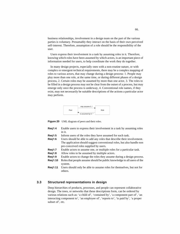
66.
business relationships, involvement in a design team on the part of the various parties is voluntary. Presumably they interact on the basis of their own perceived self-interest. Therefore, assumption of a role should be the responsibility of the user.
Users express their involvement in a task by assuming roles in it. Therefore, knowing which roles have been assumed by which actors, is an important piece of information needed for users, to help coordinate the work they do together.
In many design projects, especially ones with a non-routine nature, or with complex or emergent technical requirements, there may be a complex mapping of roles to various actors, that may change during a design process: 1. People may play more than one role, at the same time, or during different phases of a design process, 2. Certain roles may be assumed by more than one actor, 3. The roles to be filled in a design process may not be clear from the outset of a process, but may emerge only once the process is underway, 4. Conventional role names, if they exist, may not necessarily be suitable descriptions of the actions a particular actor may perform.
Figure 20 UML diagram of peers and their roles.
Req’t 4 Enable users to express their involvement in a task by assuming roles in it.
Req’t 5 Inform users of the roles they have assumed for each task.Req’t 6 Users should be able to add any roles that describe their involvement.
The application should suggest conventional roles, but also handle non pre-conceived roles supplied by users.
Req’t 7 Enable actors to assume one, or multiple roles for a particular task.Req’t 8 Allow roles to be assumed by multiple actors.Req’t 9 Enable actors to change the roles they assume during a design process.Req’t 10 Roles that people assume should be public knowledge to all users of the
system.Req’t 11 Users should only be able to assume roles for themselves, but not for
others.
3.3 Structured representations in designDeep hierarchies of products, processes, and people can represent collaborative design. The trees, or networks that these descriptions form, can be ordered by various relations such as: ‘a child of’, ‘contained by’, ‘a component part of’, ‘an interacting component to’, ‘an employee of’, ‘reports to’, ‘is paid by’, ‘a proper subset of’, etc.
Peer Role
may assume 0..*
is assumed by 0..*
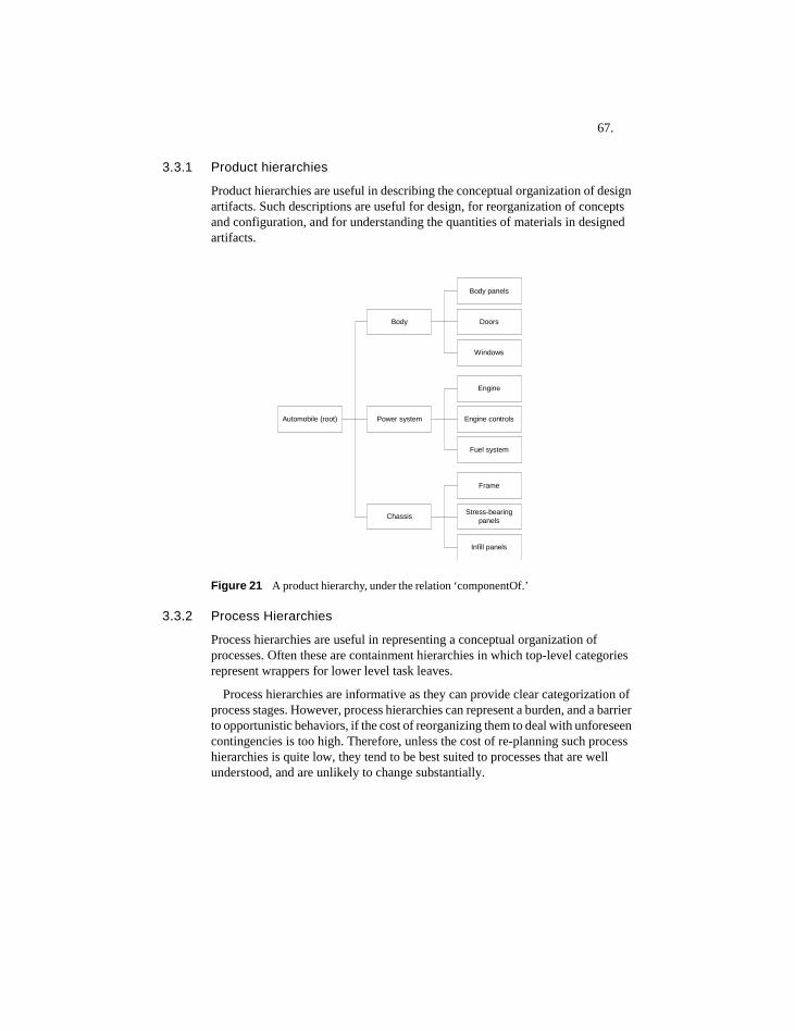
67.
3.3.1 Product hierarchies
Product hierarchies are useful in describing the conceptual organization of design artifacts. Such descriptions are useful for design, for reorganization of concepts and configuration, and for understanding the quantities of materials in designed artifacts.
Figure 21 A product hierarchy, under the relation ‘componentOf.’
3.3.2 Process Hierarchies
Process hierarchies are useful in representing a conceptual organization of processes. Often these are containment hierarchies in which top-level categories represent wrappers for lower level task leaves.
Process hierarchies are informative as they can provide clear categorization of process stages. However, process hierarchies can represent a burden, and a barrier to opportunistic behaviors, if the cost of reorganizing them to deal with unforeseen contingencies is too high. Therefore, unless the cost of re-planning such process hierarchies is quite low, they tend to be best suited to processes that are well understood, and are unlikely to change substantially.
Automobile (root)
Chassis
Power system
Body
Infill panels
Frame
Stress-bearingpanels
Windows
Body panels
Doors
Fuel system
Engine
Engine controls
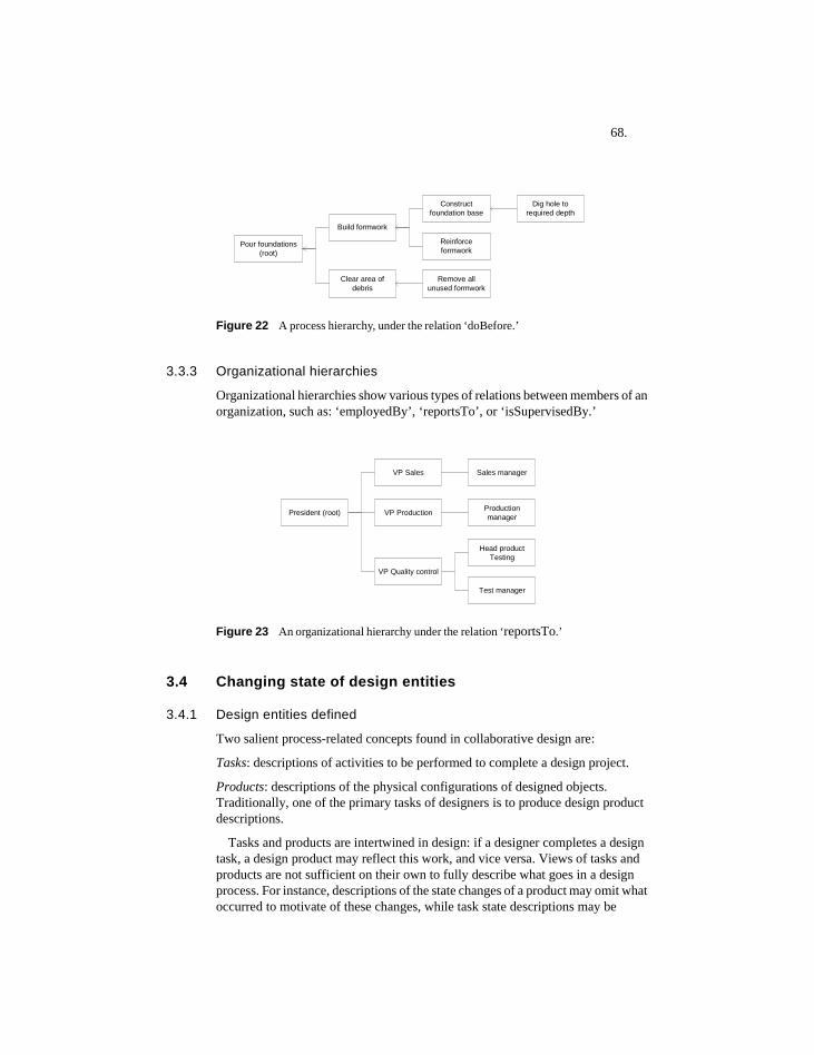
68.
Figure 22 A process hierarchy, under the relation ‘doBefore.’
3.3.3 Organizational hierarchies
Organizational hierarchies show various types of relations between members of an organization, such as: ‘employedBy’, ‘reportsTo’, or ‘isSupervisedBy.’
Figure 23 An organizational hierarchy under the relation ‘reportsTo.’
3.4 Changing state of design entities
3.4.1 Design entities defined
Two salient process-related concepts found in collaborative design are:
Tasks: descriptions of activities to be performed to complete a design project.
Products: descriptions of the physical configurations of designed objects. Traditionally, one of the primary tasks of designers is to produce design product descriptions.
Tasks and products are intertwined in design: if a designer completes a design task, a design product may reflect this work, and vice versa. Views of tasks and products are not sufficient on their own to fully describe what goes in a design process. For instance, descriptions of the state changes of a product may omit what occurred to motivate of these changes, while task state descriptions may be
Build formwork
Constructfoundation base
Pour foundations(root)
Clear area ofdebris
Remove allunused formwork
Dig hole torequired depth
Reinforceformwork
VP Sales Sales manager
President (root) VP Production Productionmanager
VP Quality control
Head productTesting
Test manager
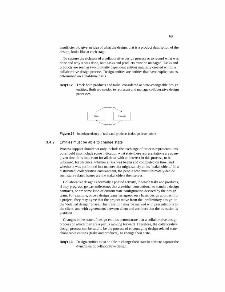
69.
insufficient to give an idea of what the design, that is a product description of the design, looks like at each stage.
To capture the richness of a collaborative design process or to record what was done and why it was done, both tasks and products must be managed. Tasks and products are seen as two mutually dependent entities naturally created within a collaborative design process. Design entities are entities that have explicit states, determined on a real-time basis.
Req’t 12 Track both products and tasks, considered as state-changeable design entities. Both are needed to represent and manage collaborative design processes.
Figure 24 Interdependency of tasks and products in design descriptions.
3.4.2 Entities must be able to change state
Process support should not only include the exchange of process representations, but should also include some indication what state these representations are at any given time. It is important for all those with an interest in this process, to be informed, for instance, whether a task was begun and completed on time, and whether it was performed in a manner that might satisfy all its ‘stakeholders.’ In a distributed, collaborative environment, the people who must ultimately decide such state-related issues are the stakeholders themselves.
Collaborative design is normally a phased activity, in which tasks and products, if they progress, go past milestones that are either conventional to standard design contracts, or are some kind of custom state configuration devised by the design team. For example, once a design team has agreed on a basic design approach for a project, they may agree that the project move from the ‘preliminary design’ to the ‘detailed design’ phase. This transition may be marked with presentations to the client, and with agreements between client and architect that the transition is justified.
Changes in the state of design entities demonstrate that a collaborative design process of which they are a part is moving forward. Therefore, the collaborative design process can be said to be the process of encouraging design-related state-changeable entities (tasks and products), to change their state.
Req’t 13 Design entities must be able to change their state in order to capture the dynamism of collaborative design.
Tasks Products
dependent on
dependent on
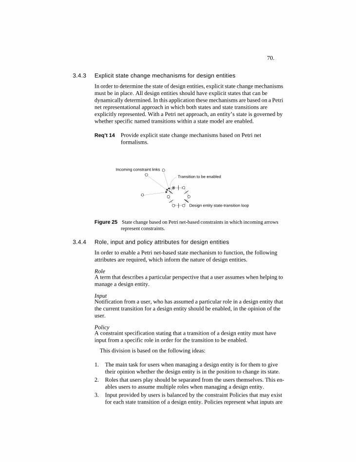
70.
3.4.3 Explicit state change mechanisms for design entities
In order to determine the state of design entities, explicit state change mechanisms must be in place. All design entities should have explicit states that can be dynamically determined. In this application these mechanisms are based on a Petri net representational approach in which both states and state transitions are explicitly represented. With a Petri net approach, an entity’s state is governed by whether specific named transitions within a state model are enabled.
Req’t 14 Provide explicit state change mechanisms based on Petri net formalisms.
Figure 25 State change based on Petri net-based constraints in which incoming arrows represent constraints.
3.4.4 Role, input and policy attributes for design entities
In order to enable a Petri net-based state mechanism to function, the following attributes are required, which inform the nature of design entities.
RoleA term that describes a particular perspective that a user assumes when helping to manage a design entity.
InputNotification from a user, who has assumed a particular role in a design entity that the current transition for a design entity should be enabled, in the opinion of the user.
PolicyA constraint specification stating that a transition of a design entity must have input from a specific role in order for the transition to be enabled.
This division is based on the following ideas:
1. The main task for users when managing a design entity is for them to give their opinion whether the design entity is in the position to change its state.
2. Roles that users play should be separated from the users themselves. This en-ables users to assume multiple roles when managing a design entity.
3. Input provided by users is balanced by the constraint Policies that may exist for each state transition of a design entity. Policies represent what inputs are
Incoming constraint links
Design entity state-transition loop
Transition to be enabled
71.
required for a single state transition, while Inputs represent inputs that users are willing to provide.
All of the above should be implemented in a voluntary, non-prescriptive fashion.
3.4.5 Basing state changes on user input
The most salient input that a design collaborator can make is to agree that a design entity can change its state, and to communicate this agreement to others on the design team. In normal design practice, making an input to a task may involve such behaviors as attending meetings, completing design drawings, offering opinions, approving design approaches, etc. State change may require much background work, in addition to the social tasks of attending meetings and making agreements.
Req’t 15 Enable users to provide input based on whether design entities can change their state, and to communicate this input to others on a design team.
3.4.6 Linking and ‘bundling’ of entities
Having stakeholders make inputs to advance state can place a large burden on users. If all design entities require input from many users, this may demand more user input than some users may be willing to provide. Normally in design practice, an entire project goes through a state change, for instance from preliminary, to detailed design. What is often important for designers is some indication that the project is progressing (and that the client is willing to continue employing the design team). This progress is indicated by state changes to the whole project. Therefore, there must be some way to ‘bundle’, or link design entities together such that if one entity manages to get sufficient user input to change its state, then dependent entities can also change their state as well.
For instance if a project changes into ‘detailed design’ this might imply that the designers have considered, in a preliminary way, such things as site and building planning, structural systems, overall style, and appropriate materials. Therefore, it should be possible with a single coordinated input from users, for many entities to change their state as a result of one entity changing its state. In this way the input of users can be leveraged or multiplied by linking their action automatically to other actions.
Note that when we talk of a project here, it concerns two concepts: one of linking design entities and their state-change behaviors, and another of organizing design entities into structured entities, such that users can view them in a conceptually ordered way. Both of these requirements can be implemented separately, since conceptually they are separate issues.
Req’t 16 Enable the state change of design entities to be linked with the state change of other design entities.
72.
3.4.7 Socially mediated and automated state change
The enabling of transitions of design entities can be done in two ways: one is based on the inputs of stakeholders who elect to participate in these design entities, while another is based on the state of other design entities to which these transitions are linked.
3.4.7.1 Socially mediated state change
A socially mediated mechanism based on the inputs of participating peers, requires that users participate with the system, and with each other, for design entities to change their state. If there is no user participation, then there is no state change. This appears suitable for design process coordination, since in many design situations there may be no automated means of determining a design entity’s state, without conferring with the stakeholders involved in the design entity.
3.4.7.2 Automated state change
The second is a mechanism in which the state change of one entity can be designed to trigger state changes in other linked entities. Using this mechanism semi-automated processes can be designed, which though ultimately based on user inputs, could have complex, cascading effects on other design entities. Users can choose to use the social-input features of the application, the semi-automated features, or could use some mix of the two.
3.4.8 Task dependencies
In project management, tasks are structured in relation to other tasks. For example, in a construction project, before pouring concrete it might be necessary to have the concrete framework ready, and the electrical conduits in place.
These form the normal branch-out, branch-in dependencies found in project management: Once one task is finished, others can proceed; or once many tasks are finished, one specific task can proceed (Hendrickson & Au, 1990).
Req’t 17 Enable the representation of ‘branch-in’, and ‘branch-out’ tasks.
3.4.9 Variability of state-transition models
An important aspect to the design of an entity is the content of the state-transition model to which the entity is linked. Often entities have conventional state models, such as those specified by building design contracts that usually specify well-defined state models, and include states such as ‘Requirements Gathering’, ‘Construction Review’, etc. These state models are common in design management, and are promoted and standardized by national architectural associations.
However, such models have the following qualities: First, they are not universally applicable. They may be appropriate in a particular country, or region, but none can be said to apply everywhere, as a matter of rational principle. Second, there is no indication that some model—for instance the one promoted by the
73.
American Institute of Architects—is becoming a standard for all design practice, in places outside the US. The cultural, business, and technical differences between different places seem to discourage such standardization. Third, such models tend to be specific to particular industries. The states that an architectural design project might enter into may be quite distinct to those that a product design project might enter into. Given the differences that might occur between local contexts and situations, users should be in the position to set state-transition models themselves, in order to specify the intended behavior of any design entity.
Req’t 18 State change models should depend on the entity, and users should be able to specify different state-transition models for each design entity.
3.4.10 State models as simple state-transition loops
Simple loops are seen as the simplest state-transition model. In that: 1. Design entity can only be in one state at a time, 2. States and transitions are connected by single incoming and outgoing arcs, thus eliminating indeterminism or complexity in transitions, and 3. Final states (e.g. ‘Retired’) connect with initial states (e.g. ‘New’). Looped state configurations encourage the idea that design entities are intended to be reused, and that design processes are often recurrent ones.
Req’t 19 To reduce complexity and indeterminism in entity state changes, represent state-transition models as simple state-transition loops.
3.5 Structured representations of design entities
3.5.1 Hierarchies of design representations
Deep, information-rich hierarchies can be very informative because they describe concepts and configurations of arbitrary depth, and can have arbitrary degrees of detail and refinement. Such descriptions can be essential in acquiring a conceptual overview with respect to an entire artifact, organization, or process. For example, contractors who construct buildings usually require an accurate picture of all the parts in a building, and what their aggregate costs will be. Individual parts of design configurations must be represented one way or another, when building complex artifacts in a modern industrial society. In computational design, information hierarchies are a standard way of doing this.
Req’t 20 Enable design entities to be arranged in information hierarchies, and enable these hierarchies to be rearranged to reflect changing circumstances.
74.
3.6 Communication between users
3.6.1 Communication of large amounts of information
Design coordination, both in general and with respect to the above requirements, means that designers when working together on a design team communicate large amounts of information. This information concerns both design entities such as tasks and products, but also the interaction that characterize how the team works together. This information concerns both individual designers communicating between themselves in a point-to-point fashion, but is also needed for the team as a whole to come to some common view of the design project’s progress.
It is assumed that this communication should be computer-mediated, and that it uses the Internet as its transport network.
Req’t 21 Provide a communication network that connects users together, and enables them to view the work of their design colleagues.
When people do work together over a computer network they need to have their identities known to each other, and that there be some assurance that users are who they say they are. This involves creation of online identities, in which there are some security provisions such that users’ identities cannot be easily borrowed or stolen.
Req’t 22 Enable users to create secure online identities.
3.6.2 Asynchronous contributions
Design teams, especially those working on complex, multi-disciplinary projects, often have members from more than one country. This means that design teams may be geographically distributed, and may work at different times during the day, due to time-zone variations. Designers therefore, may not be in the position to work synchronously on items of common interest with fellow members of their design teams.
Req’t 23 Enable users to make asynchronous contributions to all domain objects.
3.6.3 Decentralized configuration of software and information
With the geographical distribution of design team members, and with the possibility of non-hierarchical nature of design team configurations, it may not be clear where software components should be situated or where generated data should be stored.
This tendency towards decentralization is given more power with a non-prescriptive approach to design process management in which no party—with the possible exception of the software developers themselves—are in a position of power or authority with respect to other users.
75.
From the technical point of view however, the required functionality could be completed in either a centralized or decentralized software implementation. From a user’s point of view, such implementation details may not make any difference to their experience, even those with concerns about social hierarchies and how they are manifested in software.
From a developer’s point of view, however, in the current domain decentralized software has some compelling advantages:
1. Ease of communication system development: P2P frameworks provide com-munication facilities that link users, and enable them to build social forums (i.e. peergroups) for their interactions.
2. Modularization of communication components: using P2P all of the commu-nication requirements are implemented in the P2P component, and are sepa-rated from other domain components such as those concerned with roles and inputs from users.
3. Reduction of the number of software components: using P2P technologies, only one software package has to deployed or maintained—the client por-tion—rather than two or more.

76.
77.
4 Actors, use cases, and required objects
4.1 IntroductionThis chapter describes the design of the application, in terms of software development constructs such as actors and use cases, without specifying particular software implementations or technologies.
4.2 System actorsThe actor construct describes roles that a user can play when using the application. Therefore, individual users could play various actor roles while using the application. Actors represent the outside world when it interacts with the software. As Jacobsen points out, unlike other objects in the application, an actor’s actions are non-deterministic (Jacobson et al., 1992, p.127).
4.2.1 Peer• Someone who uses the software in the context of a collaborative distributed
design team.• A Peer models design entities, assumes roles in them, and provides inputs. This
user action enables them to change their state.• Peers connect to other Peers, using this system and an Internet connection.
4.2.1.1 Discussion
How to define actor in a system is an important decision because choice of actors indicates how processes are structured outside of the relatively abstract and ideal world of the software system itself.
Currently there is only one class of user, or actor—that of the ‘Peer.’
A peer, which comes from the domain of P2P software, reflects the basic approach found in P2P computing, which tends to collapse multiple user categories into single ones. This approach is a result of the basic technology of P2P computing, but also reflects non-technical concerns common in the P2P community, such as reduction of the social stratification of users, encouragement of open processes, and provision of resources to enable distributed phenomena to self-organize. In general, technical systems of this sort, especially ones that deal with distributed social processes, cannot be designed without consideration of these types of non-technical issues.
However, the intention in this chapter is to describe a system design without assuming that a particular implementation is required. Therefore, despite being named ‘peer’ which suggests that P2P implementations should be used, it should still be possible to implement the described system and its functionality using a non-P2P implementation.
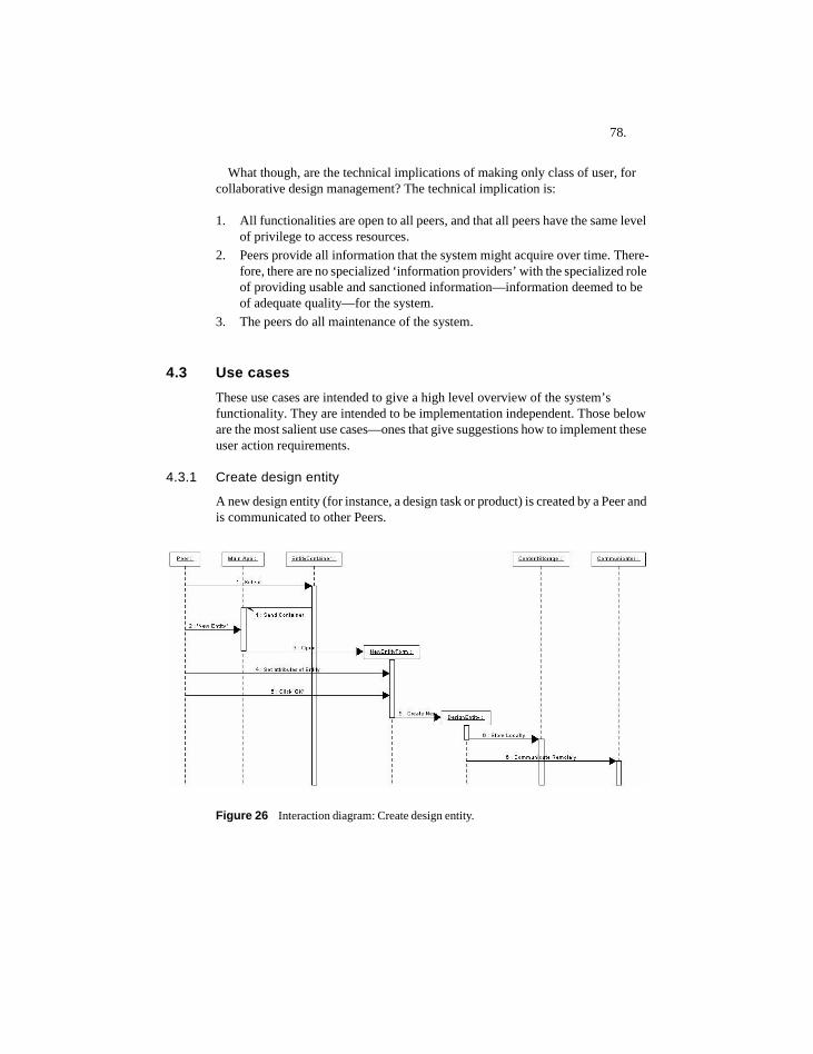
78.
What though, are the technical implications of making only class of user, for collaborative design management? The technical implication is:
1. All functionalities are open to all peers, and that all peers have the same level of privilege to access resources.
2. Peers provide all information that the system might acquire over time. There-fore, there are no specialized ‘information providers’ with the specialized role of providing usable and sanctioned information—information deemed to be of adequate quality—for the system.
3. The peers do all maintenance of the system.
4.3 Use casesThese use cases are intended to give a high level overview of the system’s functionality. They are intended to be implementation independent. Those below are the most salient use cases—ones that give suggestions how to implement these user action requirements.
4.3.1 Create design entity
A new design entity (for instance, a design task or product) is created by a Peer and is communicated to other Peers.
Figure 26 Interaction diagram: Create design entity.
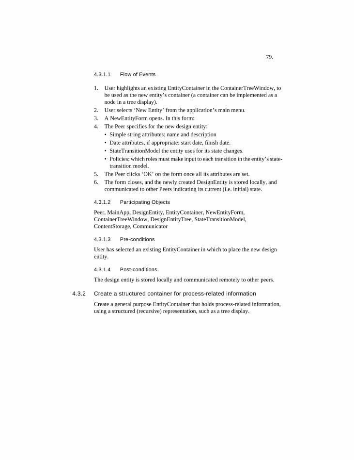
79.
4.3.1.1 Flow of Events
1. User highlights an existing EntityContainer in the ContainerTreeWindow, to be used as the new entity’s container (a container can be implemented as a node in a tree display).
2. User selects ‘New Entity’ from the application’s main menu.3. A NewEntityForm opens. In this form:4. The Peer specifies for the new design entity:
• Simple string attributes: name and description• Date attributes, if appropriate: start date, finish date.• StateTransitionModel the entity uses for its state changes.• Policies: which roles must make input to each transition in the entity’s state-
transition model.5. The Peer clicks ‘OK’ on the form once all its attributes are set.6. The form closes, and the newly created DesignEntity is stored locally, and
communicated to other Peers indicating its current (i.e. initial) state.
4.3.1.2 Participating Objects
Peer, MainApp, DesignEntity, EntityContainer, NewEntityForm, ContainerTreeWindow, DesignEntityTree, StateTransitionModel, ContentStorage, Communicator
4.3.1.3 Pre-conditions
User has selected an existing EntityContainer in which to place the new design entity.
4.3.1.4 Post-conditions
The design entity is stored locally and communicated remotely to other peers.
4.3.2 Create a structured container for process-related information
Create a general purpose EntityContainer that holds process-related information, using a structured (recursive) representation, such as a tree display.
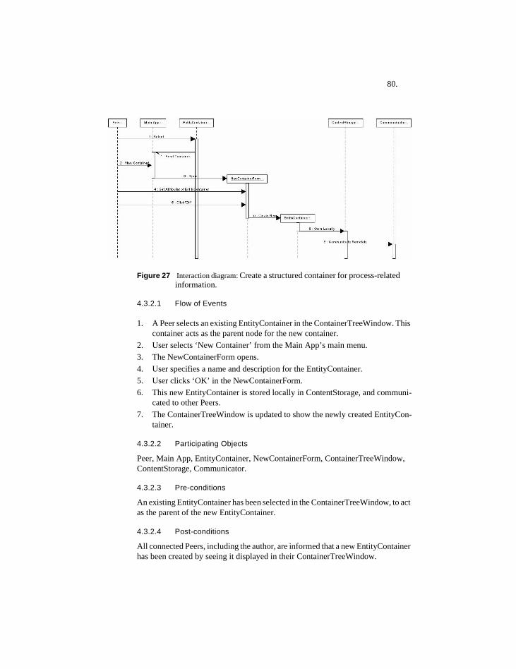
80.
Figure 27 Interaction diagram: Create a structured container for process-related information.
4.3.2.1 Flow of Events
1. A Peer selects an existing EntityContainer in the ContainerTreeWindow. This container acts as the parent node for the new container.
2. User selects ‘New Container’ from the Main App’s main menu.3. The NewContainerForm opens.4. User specifies a name and description for the EntityContainer.5. User clicks ‘OK’ in the NewContainerForm.6. This new EntityContainer is stored locally in ContentStorage, and communi-
cated to other Peers. 7. The ContainerTreeWindow is updated to show the newly created EntityCon-
tainer.
4.3.2.2 Participating Objects
Peer, Main App, EntityContainer, NewContainerForm, ContainerTreeWindow, ContentStorage, Communicator.
4.3.2.3 Pre-conditions
An existing EntityContainer has been selected in the ContainerTreeWindow, to act as the parent of the new EntityContainer.
4.3.2.4 Post-conditions
All connected Peers, including the author, are informed that a new EntityContainer has been created by seeing it displayed in their ContainerTreeWindow.
81.
4.3.3 Assume role in a design entity
A Peer signs up for a role in an existing design entity. This role applies to all transitions of this design entity.
Figure 28 Interaction diagram: Assume role in a design entity.
4.3.3.1 Flow of Events
1. User highlights an existing DesignEntity in the ContainerTreeWindow (a De-signEntity can be implemented as a leaf node in a tree display).
2. User selects ‘New Role’ from the Main App’s main menu.3. A NewRoleForm opens.4. The user either selects an existing Role, or adds a new Role term.5. The user clicks ‘OK’ and the NewRoleForm closes. 6. The new Role that links the DesignEntity to the role and its author is commu-
nicated to other Peers. 7. The DesignEntity’s display in the ContainerTreeWindow is updated to reflect
the new role addition.
4.3.3.2 Participating Objects
Peer, MainApp, DesignEntity, NewRoleForm, Role, RoleName, DesignEntityTree, ContainerTreeWindow, Communicator.
4.3.3.3 Pre-conditions
The ContainerTreeWindow is open, and a DesignEntity is selected within it.
4.3.3.4 Post-conditions
Peers are informed that the Peer, who authored the new Role, has assumed a Role in the entity.
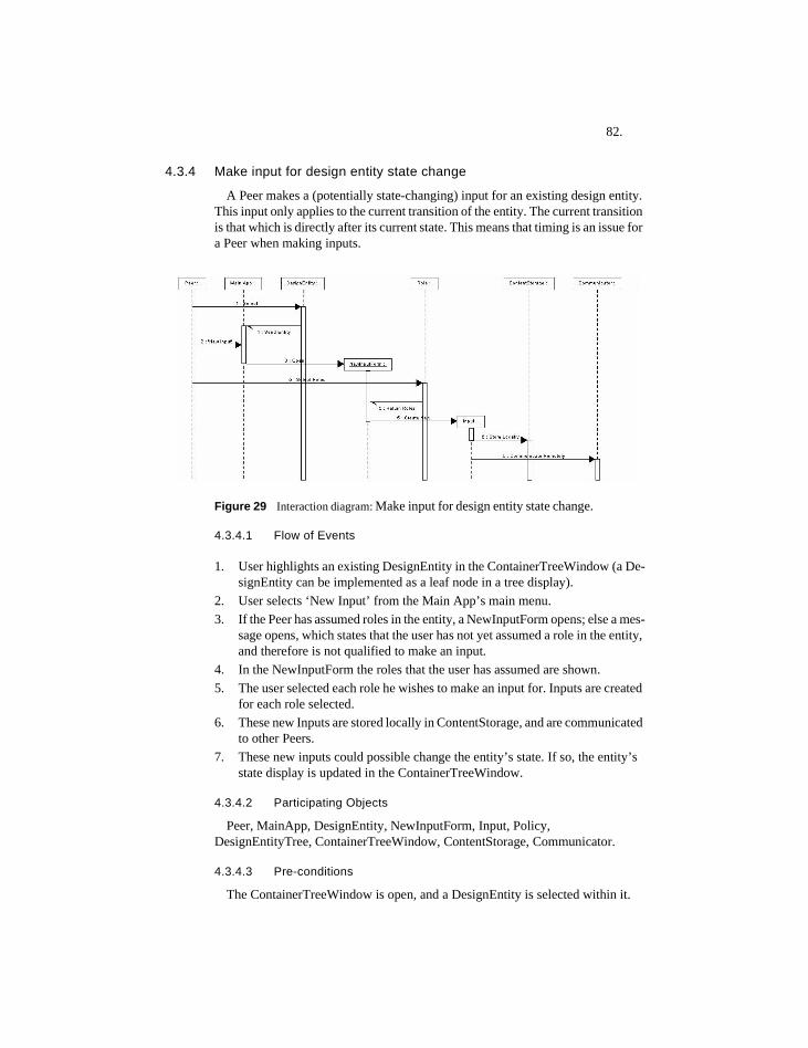
82.
4.3.4 Make input for design entity state change
A Peer makes a (potentially state-changing) input for an existing design entity. This input only applies to the current transition of the entity. The current transition is that which is directly after its current state. This means that timing is an issue for a Peer when making inputs.
Figure 29 Interaction diagram: Make input for design entity state change.
4.3.4.1 Flow of Events
1. User highlights an existing DesignEntity in the ContainerTreeWindow (a De-signEntity can be implemented as a leaf node in a tree display).
2. User selects ‘New Input’ from the Main App’s main menu.3. If the Peer has assumed roles in the entity, a NewInputForm opens; else a mes-
sage opens, which states that the user has not yet assumed a role in the entity, and therefore is not qualified to make an input.
4. In the NewInputForm the roles that the user has assumed are shown.5. The user selected each role he wishes to make an input for. Inputs are created
for each role selected.6. These new Inputs are stored locally in ContentStorage, and are communicated
to other Peers. 7. These new inputs could possible change the entity’s state. If so, the entity’s
state display is updated in the ContainerTreeWindow.
4.3.4.2 Participating Objects
Peer, MainApp, DesignEntity, NewInputForm, Input, Policy, DesignEntityTree, ContainerTreeWindow, ContentStorage, Communicator.
4.3.4.3 Pre-conditions
The ContainerTreeWindow is open, and a DesignEntity is selected within it.
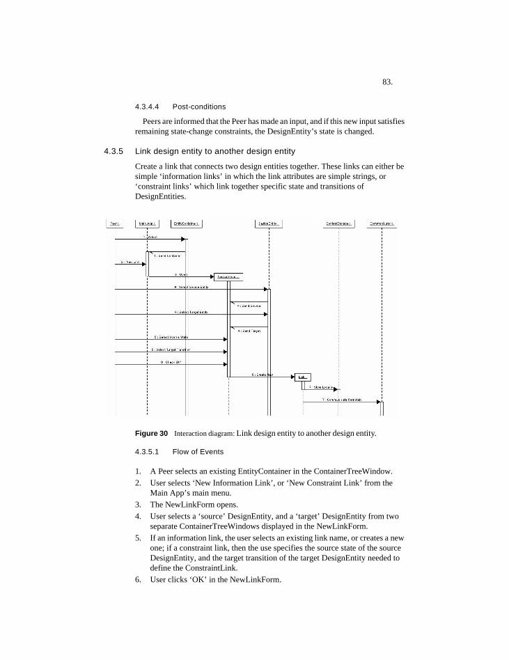
83.
4.3.4.4 Post-conditions
Peers are informed that the Peer has made an input, and if this new input satisfies remaining state-change constraints, the DesignEntity’s state is changed.
4.3.5 Link design entity to another design entity
Create a link that connects two design entities together. These links can either be simple ‘information links’ in which the link attributes are simple strings, or ‘constraint links’ which link together specific state and transitions of DesignEntities.
Figure 30 Interaction diagram: Link design entity to another design entity.
4.3.5.1 Flow of Events
1. A Peer selects an existing EntityContainer in the ContainerTreeWindow.2. User selects ‘New Information Link’, or ‘New Constraint Link’ from the
Main App’s main menu.3. The NewLinkForm opens.4. User selects a ‘source’ DesignEntity, and a ‘target’ DesignEntity from two
separate ContainerTreeWindows displayed in the NewLinkForm.5. If an information link, the user selects an existing link name, or creates a new
one; if a constraint link, then the use specifies the source state of the source DesignEntity, and the target transition of the target DesignEntity needed to define the ConstraintLink.
6. User clicks ‘OK’ in the NewLinkForm.
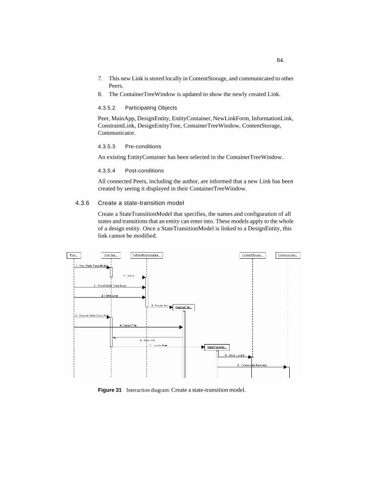
84.
7. This new Link is stored locally in ContentStorage, and communicated to other Peers.
8. The ContainerTreeWindow is updated to show the newly created Link.
4.3.5.2 Participating Objects
Peer, MainApp, DesignEntity, EntityContainer, NewLinkForm, InformationLink, ConstraintLink, DesignEntityTree, ContainerTreeWindow, ContentStorage, Communicator.
4.3.5.3 Pre-conditions
An existing EntityContainer has been selected in the ContainerTreeWindow.
4.3.5.4 Post-conditions
All connected Peers, including the author, are informed that a new Link has been created by seeing it displayed in their ContainerTreeWindow.
4.3.6 Create a state-transition model
Create a StateTransitionModel that specifies, the names and configuration of all states and transitions that an entity can enter into. These models apply to the whole of a design entity. Once a StateTransitionModel is linked to a DesignEntity, this link cannot be modified.
Figure 31 Interaction diagram: Create a state-transition model.
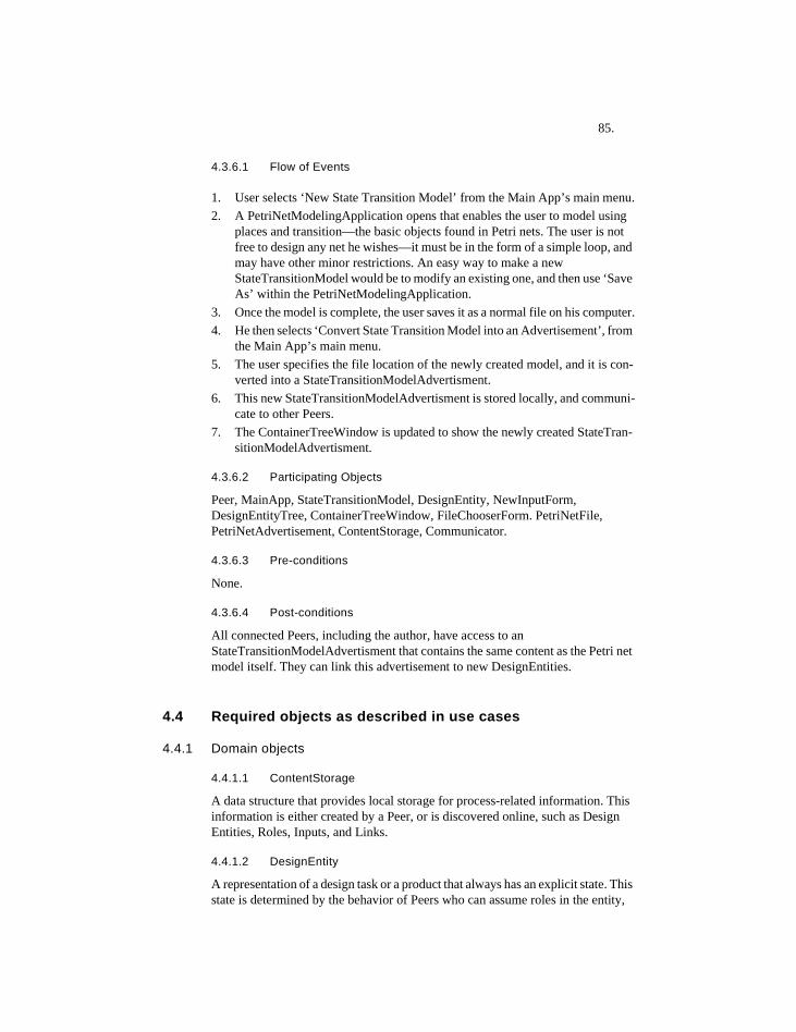
85.
4.3.6.1 Flow of Events
1. User selects ‘New State Transition Model’ from the Main App’s main menu.2. A PetriNetModelingApplication opens that enables the user to model using
places and transition—the basic objects found in Petri nets. The user is not free to design any net he wishes—it must be in the form of a simple loop, and may have other minor restrictions. An easy way to make a new StateTransitionModel would be to modify an existing one, and then use ‘Save As’ within the PetriNetModelingApplication.
3. Once the model is complete, the user saves it as a normal file on his computer.4. He then selects ‘Convert State Transition Model into an Advertisement’, from
the Main App’s main menu. 5. The user specifies the file location of the newly created model, and it is con-
verted into a StateTransitionModelAdvertisment.6. This new StateTransitionModelAdvertisment is stored locally, and communi-
cate to other Peers. 7. The ContainerTreeWindow is updated to show the newly created StateTran-
sitionModelAdvertisment.
4.3.6.2 Participating Objects
Peer, MainApp, StateTransitionModel, DesignEntity, NewInputForm, DesignEntityTree, ContainerTreeWindow, FileChooserForm. PetriNetFile, PetriNetAdvertisement, ContentStorage, Communicator.
4.3.6.3 Pre-conditions
None.
4.3.6.4 Post-conditions
All connected Peers, including the author, have access to an StateTransitionModelAdvertisment that contains the same content as the Petri net model itself. They can link this advertisement to new DesignEntities.
4.4 Required objects as described in use cases
4.4.1 Domain objects
4.4.1.1 ContentStorage
A data structure that provides local storage for process-related information. This information is either created by a Peer, or is discovered online, such as Design Entities, Roles, Inputs, and Links.
4.4.1.2 DesignEntity
A representation of a design task or a product that always has an explicit state. This state is determined by the behavior of Peers who can assume roles in the entity,
86.
and make state-changing inputs to them. A DesignEntity’s state changes are modeled by a state-transition model that is specified at its construction.
4.4.1.3 EntityContainer (Peergroup)
A data container that holds various types of process-related information. EntityContainer can be implemented as a folder in a hierarchical tree display.
4.4.1.4 Input
Notification from a user, who has assumed a particular role in a design entity that the current transition for a design entity should be enabled, in the opinion of the user.
4.4.1.5 Link
A directed edge that links two design entities together. Links have a named value. Links are of two types: information links, and constraint links. Information links connect whole entities together, while constraint links connect the state of a source entity to the transition of the target entity.
4.4.1.6 Peer
The user of the application. Peers are responsible for providing information for the application, and for providing appropriate inputs, which allow DesignEntities to change their state. Peers exchange process-related information between themselves.
4.4.1.7 PetriNetAdvertisement
A text-based document exchanged between Peers that represents the content of a state-transition model.
4.4.1.8 PetriNetFile
The binary file that represents a state-transition model for use by a Petri net application. A PetriNetFile is used to create a PetriNetAdvertisement, which can be shared between Peers.
4.4.1.9 Policy
A constraint specification stating that a transition of a design entity must have input from a specific role, in order for the transition to be enabled.
4.4.1.10 Role
A name that describes a particular perspective that a user assumes when helping to manage a design entity.
4.4.1.11 StateTransitionModel
A model that explicitly represents the states and transition that a DesignEntity can enter into, throughout its life span. These models form simple closed state-
87.
transition loops. State-transition models can be modeled using Petri nets, which explicitly model both states and transitions.
4.4.2 Interface Objects
4.4.2.1 ContainerTreeWindow
A window that displays a hierarchical representation of EntityContainers, and shows the process-related information that EntityContainers can contain.
4.4.2.2 DesignEntityTree
The hierarchical tree representation that has EntityContainers as its nodes, and various types of process-related information as its leaves.
4.4.2.3 FileChooserForm
A form that enables users to choose a binary file from a file directory.
4.4.2.4 NewContainerForm
A form that enables users to specify a name and description of a new EntityContainer.
4.4.2.5 NewEntityForm
A form that enables a Peer to specify all needed attributes for a new DesignEntity. The most important of these are its name, and the state-transition model that governs its state changes.
4.4.2.6 NewInputForm
A form that enables a Peer to make a potentially state-changing input for a DesignEntity, from the perspective of a Role that the Peer has previously assumed.
4.4.2.7 NewRoleForm
A form that enables a Peer to assume a Role in a DesignEntity. Peers can choose existing role names, or they can create new ones.
4.4.2.8 Petri net Modeling Application
An application that enables a Peer to model and view state-transition loops.
4.4.3 Control Objects
4.4.3.1 Communicator
The object that enables process-related information to be communicated with other Peers over the Internet.

88.
4.4.3.2 Main App
The application that provides users with access to needed forms to create all required domain objects, and enables Peers to communicate with each other.
89.
5 Application design and implementation
5.1 What was implementedThe software implementation side of this research developed with the idea that P2P software, and distributed processes in general, can be used and extended, to serve the domain of design process management. Some ideas in the research could be implemented using a variety of technologies, while others are dependent on the P2P approach to make them viable.
5.1.1 Role of JXTA
The application is based on the open-source JXTA point-to-point (P2P) protocol-based framework. It would be possible to build a traditional non-decentralized client/server application using the same use cases of this dissertation. However, JXTA and how it operates, is more in line with the basic intent of the dissertation, which favors non-prescriptive and decentralized design communication and coordination.
JXTA is an open-source development project of Sun Microsystems Inc. that provides all the necessary infrastructure to build secure P2P applications in Java and in other languages. The objectives of JXTA are: • Interoperability: to enable different peer-to-peer systems and communities to
interact.• Platform independence: to enable P2P communication between multiple/
diverse languages, systems, and networks. • Ubiquity: to handle interactive communication between a wide range of digital
devices (Sun Microsystems, 2002).
The JXTA framework appears well designed and comprehensive from a software engineering perspective. JXTA is also an active area of research and development, with many active projects concerning various aspects of distributed computing. Its open source nature enables easy customization and reuse of its code. The current application leverages and expands the functionality of JXTA to suit the domain of design process coordination.
5.1.2 Design Process Modeler (DPM) application
The DPM application is conceived as an application that enables users to model and coordinate their design processes. This enables users to define collaboratively the state of so-called design entities, such as Design Tasks and Products.
Users of the DPM application can customize the use of the application to suit their particular design processes. One of the most important ways that users can customize the application is the ability of users to define their own state-transition models (‘loops’) for each design entity they define.
90.
5.1.3 Peergroups
In JXTA, peers can self-organize into groups called peergroups. Peergroups are used as venues of interaction for groups of stakeholders interested in various aspects of a design project. Within the bounds of peergroups, all communication and data exchange takes place. Using peergroups, member peers are able to easily share specialized information. To do this peers must become members of the peergroup.
Peergroups enable the creation of a well-defined scoping, security, and monitoring environment (Oaks et al., 2002). Without the construct of a peergroup, sharing information within a distributed community is much less efficient, since then all information would have to be shared with all known peers, rather than a smaller subset of these peers.
5.1.3.1 Peergroups as data containers and online social venues
Peergroups enable the integration of both design data, and people who have some kind of interest or stake in these design data. Types of entities that can be published and displayed in peergroups include: • member peers of the peergroup,• sub-peergroups of the peergroup,• advertisements that represent design entities,• links that define both so-called information and constraint links between design
entities in the peergroup, and• Petri net models that represent state-transition loops.
In this application, hierarchical peergroups are used as containers for design data. The hierarchies described by peergroups do not have any formal semantics associated with them, beyond that which the users choose to apply to them.
5.1.3.2 Peergroups as forum for advertisements
In JXTA, documents called ‘advertisements’ are used to represent persistent and semi-persistent design data. Advertisements are the principal data communicated between peers. In JXTA, advertisements are implemented as text-based XML-encoded documents. An important core of the functionality of JXTA is the conversion of these XML documents from a simple text-based form, which is stored and communicated between peers to a Java (or other language) object representation that is used internally within JXTA-based applications.
The data foundation of this application is various advertisement representations. These are sub-classes of the advertisement classes found in JXTA. All entities that form the contents of peergroups have advertisements associated with them. For example, Peers are represented by PeerAdvertisements, DesignEntities by DesignEntityAdvertisements, and Links by LinkAdvertisements. These advertisements are communicated in a P2P manner between peers.
There are two basic ways of sending information in a P2P system: peers can send messages to other peers directly, or peers can publish advertisements within peergroups, where other peers who might frequent these peergroups can view
91.
them. In the message-passing approach, users communicate with individuals, while with the peergroup and advertisement approach users communicate with self-organizing social forums, represented by the peergroup. The DPM application uses the peergroup and advertisement approach.
5.1.3.3 DPM peergroups are distinguished
DPM instantiates a peergroup called ‘dpmNet’ when it opens. All DPM users join the same DPM peergroup (rather than a peergroup with simply the same name). To do this DPM must have access to a persistent, that is text-based record of the peergroup ID for this DPM peergroup, in order to re-create it each time a user opens the DPM application. In JXTA various entities are distinguished by unique IDs, rather than by their names.
5.1.4 Peergroup hierarchies
DPM enables users to build peergroup hierarchies and thereby define areas of interest in a structured, organized way. Users describe these areas of interest by the names they give to peergroups, and sub-peergroups. Hierarchically structured peergroups combine the conceptual modeling capability of hierarchies—which form a core of computational support for design, with the ability for people to self-organize these peergroups into any configuration they wish.
Peergroups can form hierarchical structures of arbitrary depth. They can provide a social environment in which to share a wide variety of information. They can thus serve as a metaphorical ‘place’ in which various types of information can be shared between self-selected parties.
The application does not however prescribe a tree-structuring relation that would lend formal meanings to peergroup hierarchies. This is up to users to do themselves. The application does not infer any semantics from the peergroup a design entity is located. Therefore, hierarchies created by users are descriptive, informal ones, rather than ones with formal properties, such as inheritance. This informality causes no confusion within JXTA itself, since it identifies each peergroup as a unique entity through reference to its unique ID.
This informal approach gives users the freedom to label peergroups any way they wish, and also enables them to experiment with various hierarchical structures. On the negative side, it enables users to create hierarchies that may be arranged in a disorderly, or conceptually confusing manner. As the information sciences clearly show, formation of conceptually clear information categorization schemes is surprisingly difficult—even for professionals—and requires iterated processes of negotiation between interested parties before they are properly designed (Bowker & Star, 1999).
5.1.4.1 Hierarchical aspects of peergroups found in JXTA
Hierarchical aspects of a DPM peergroup take their basic hierarchical nature from JXTA. In JXTA, all peergroups are created based on a parent peergroup. DPM uses this fact to create and re-create hierarchical peergroups. Therefore, peergroup hierarchies are built into JXTA’s implementation, although JXTA applications
92.
generally do not yet make use of this feature. In order to create any peergroup in JXTA you must first have an existing peergroup to act as its parent. A method of the parent peergroup called newGroup() is used. For example:
PeerGroup newChildPeerGroup = parentPG.newGroup(childPgAdv);
Here, a new peergroup called ‘newChildPeerGroup’ is created using a peergroup advertisement called ‘childPgAdv.’
A peergroup advertisement describes a peer group, and references additional information required for instantiating it. The PeerGroup method newGroup performs the task of instantiating a PeerGroup given its advertisement. Peergroups are formed as a collection of peers that have agreed upon a common set of services. Each peer group is assigned a unique peer group ID and a peer group advertisement. The peer group advertisement contains a ModuleSpecID, which refers to a module specification for this peer group (Sun Microsystems, 2002).
Once a new child peergroup is created, it can be published both locally and remotely. This involves a peergroup advertisement being created by JXTA and communicating it to other peers.
5.1.5 State change mechanisms
5.1.5.1 Two separate state constraint mechanisms
Design entities change state according to two separate constraint mechanisms. If both of these mechanisms provide no constraint, then the entity is allowed to change state to its ‘next state.’ This next state is determined by the content of a state-transition loop that is linked to the entity by its author at the time of its construction.
The first mechanism involves so-called Input Constraints, while the second involves Link Constraints. Input constraints are ones that require peer input to an entity, while link constraints are constraints imposed by the state of other design entities.
Links constraints specify that a linked object (the source of the link) must attain a certain state before a specific transition of an entity (the target of the link) can be enabled. For example, a peer could specify that a task must be ‘retired’ (fully completed) before another task’s transition ‘agree to perform’ can be enabled. Link constraints do not need user input except when they are first defined, and as implemented enable a fine degree of constraint specification. This enables a greater level of control then simply stating a task must be ‘done’ before another can be started.
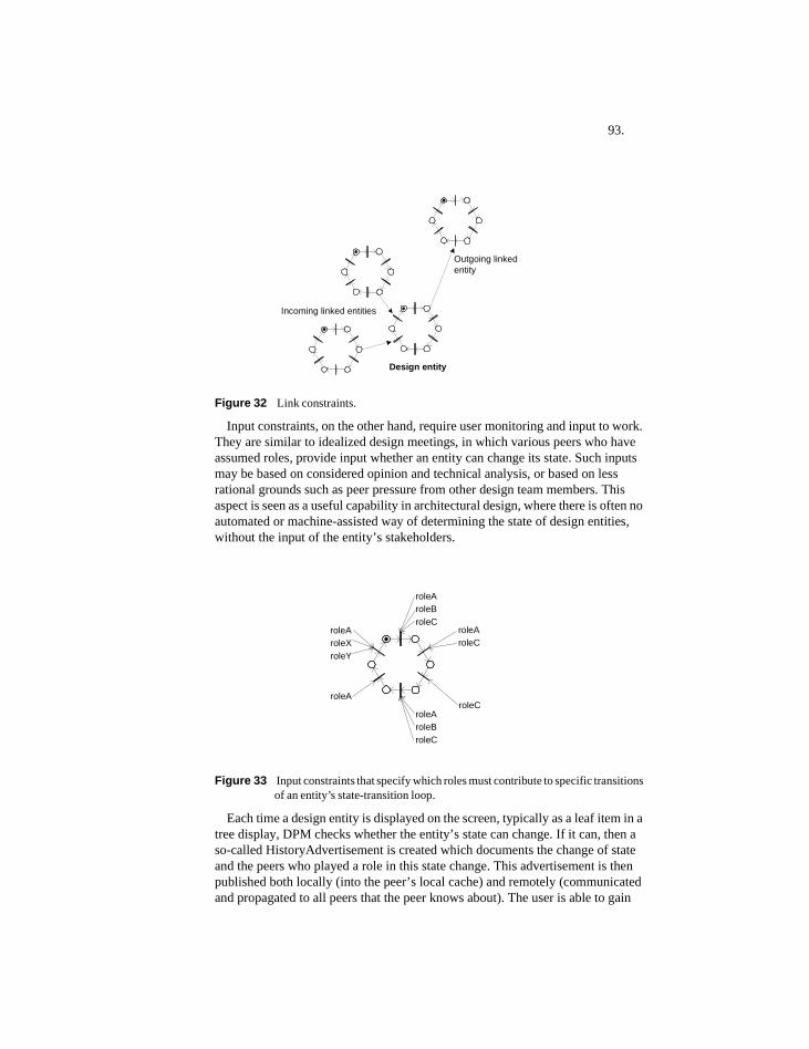
93.
Figure 32 Link constraints.
Input constraints, on the other hand, require user monitoring and input to work. They are similar to idealized design meetings, in which various peers who have assumed roles, provide input whether an entity can change its state. Such inputs may be based on considered opinion and technical analysis, or based on less rational grounds such as peer pressure from other design team members. This aspect is seen as a useful capability in architectural design, where there is often no automated or machine-assisted way of determining the state of design entities, without the input of the entity’s stakeholders.
Figure 33 Input constraints that specify which roles must contribute to specific transitions of an entity’s state-transition loop.
Each time a design entity is displayed on the screen, typically as a leaf item in a tree display, DPM checks whether the entity’s state can change. If it can, then a so-called HistoryAdvertisement is created which documents the change of state and the peers who played a role in this state change. This advertisement is then published both locally (into the peer’s local cache) and remotely (communicated and propagated to all peers that the peer knows about). The user is able to gain
Incoming linked entities
Outgoing linkedentity
Design entity
roleAroleC
roleCroleAroleBroleC
roleA
roleAroleXroleY
roleAroleBroleC
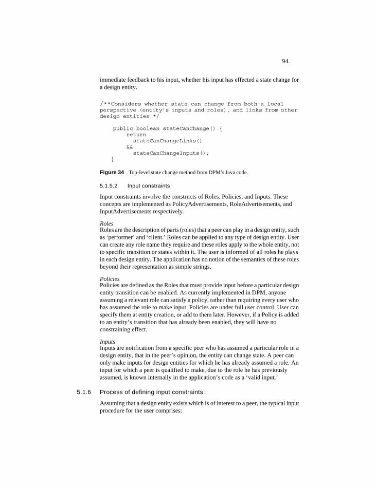
94.
immediate feedback to his input, whether his input has effected a state change for a design entity.
/**Considers whether state can change from both a local perspective (entity's inputs and roles), and links from other design entities */
public boolean stateCanChange() { return
stateCanChangeLinks() &&
stateCanChangeInputs();}
Figure 34 Top-level state change method from DPM’s Java code.
5.1.5.2 Input constraints
Input constraints involve the constructs of Roles, Policies, and Inputs. These concepts are implemented as PolicyAdvertisements, RoleAdvertisements, and InputAdvertisements respectively.
RolesRoles are the description of parts (roles) that a peer can play in a design entity, such as ‘performer’ and ‘client.’ Roles can be applied to any type of design entity. User can create any role name they require and these roles apply to the whole entity, not to specific transition or states within it. The user is informed of all roles he plays in each design entity. The application has no notion of the semantics of these roles beyond their representation as simple strings.
PoliciesPolicies are defined as the Roles that must provide input before a particular design entity transition can be enabled. As currently implemented in DPM, anyone assuming a relevant role can satisfy a policy, rather than requiring every user who has assumed the role to make input. Policies are under full user control. User can specify them at entity creation, or add to them later. However, if a Policy is added to an entity’s transition that has already been enabled, they will have no constraining effect.
InputsInputs are notification from a specific peer who has assumed a particular role in a design entity, that in the peer’s opinion, the entity can change state. A peer can only make inputs for design entities for which he has already assumed a role. An input for which a peer is qualified to make, due to the role he has previously assumed, is known internally in the application’s code as a ‘valid input.’
5.1.6 Process of defining input constraints
Assuming that a design entity exists which is of interest to a peer, the typical input procedure for the user comprises:
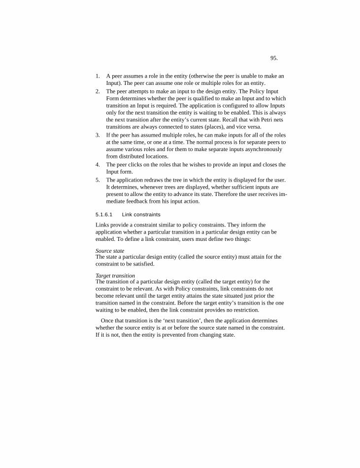
95.
1. A peer assumes a role in the entity (otherwise the peer is unable to make an Input). The peer can assume one role or multiple roles for an entity.
2. The peer attempts to make an input to the design entity. The Policy Input Form determines whether the peer is qualified to make an Input and to which transition an Input is required. The application is configured to allow Inputs only for the next transition the entity is waiting to be enabled. This is always the next transition after the entity’s current state. Recall that with Petri nets transitions are always connected to states (places), and vice versa.
3. If the peer has assumed multiple roles, he can make inputs for all of the roles at the same time, or one at a time. The normal process is for separate peers to assume various roles and for them to make separate inputs asynchronously from distributed locations.
4. The peer clicks on the roles that he wishes to provide an input and closes the Input form.
5. The application redraws the tree in which the entity is displayed for the user. It determines, whenever trees are displayed, whether sufficient inputs are present to allow the entity to advance its state. Therefore the user receives im-mediate feedback from his input action.
5.1.6.1 Link constraints
Links provide a constraint similar to policy constraints. They inform the application whether a particular transition in a particular design entity can be enabled. To define a link constraint, users must define two things:
Source stateThe state a particular design entity (called the source entity) must attain for the constraint to be satisfied.
Target transition The transition of a particular design entity (called the target entity) for the constraint to be relevant. As with Policy constraints, link constraints do not become relevant until the target entity attains the state situated just prior the transition named in the constraint. Before the target entity’s transition is the one waiting to be enabled, then the link constraint provides no restriction.
Once that transition is the ‘next transition’, then the application determines whether the source entity is at or before the source state named in the constraint. If it is not, then the entity is prevented from changing state.
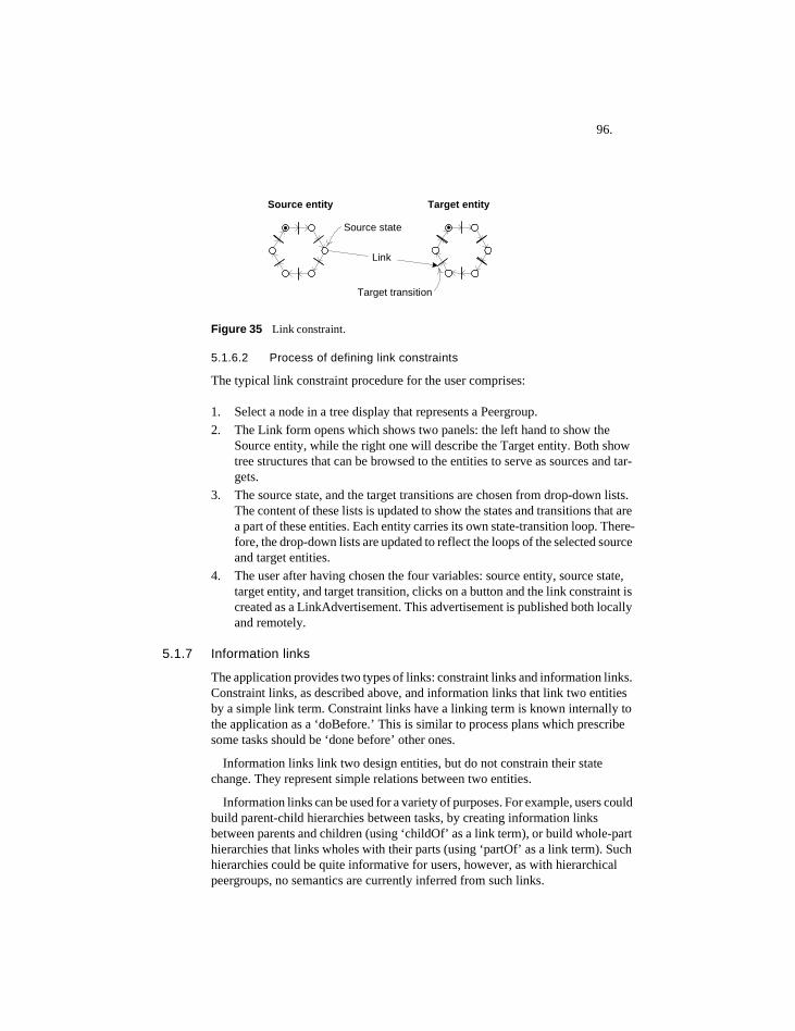
96.
Figure 35 Link constraint.
5.1.6.2 Process of defining link constraints
The typical link constraint procedure for the user comprises:
1. Select a node in a tree display that represents a Peergroup. 2. The Link form opens which shows two panels: the left hand to show the
Source entity, while the right one will describe the Target entity. Both show tree structures that can be browsed to the entities to serve as sources and tar-gets.
3. The source state, and the target transitions are chosen from drop-down lists. The content of these lists is updated to show the states and transitions that are a part of these entities. Each entity carries its own state-transition loop. There-fore, the drop-down lists are updated to reflect the loops of the selected source and target entities.
4. The user after having chosen the four variables: source entity, source state, target entity, and target transition, clicks on a button and the link constraint is created as a LinkAdvertisement. This advertisement is published both locally and remotely.
5.1.7 Information links
The application provides two types of links: constraint links and information links. Constraint links, as described above, and information links that link two entities by a simple link term. Constraint links have a linking term is known internally to the application as a ‘doBefore.’ This is similar to process plans which prescribe some tasks should be ‘done before’ other ones.
Information links link two design entities, but do not constrain their state change. They represent simple relations between two entities.
Information links can be used for a variety of purposes. For example, users could build parent-child hierarchies between tasks, by creating information links between parents and children (using ‘childOf’ as a link term), or build whole-part hierarchies that links wholes with their parts (using ‘partOf’ as a link term). Such hierarchies could be quite informative for users, however, as with hierarchical peergroups, no semantics are currently inferred from such links.
Source entity Target entity
Source state
Target transition
Link
97.
Information links are represented with three parts:
1. A source entity2. A link string that defines the link. For example: ‘related to’, ‘composed of’,
‘part of’, ‘depends on’, etc.3. A target entity
Users are free to add any kind of link string they wish. Therefore information links define labelled edges between design entities, in which the entities are nodes in a graph.
Information links have the advantage of linking two entities that may be situated in distant peergroups, and connecting them in an easily accessible manner. This can provide useful information for process coordination and planning.
5.1.8 Managing data with ‘Content Storage’
With this application there is need for management of the large amount of data—XML-encoded advertisements—communicated between peers. This is accomplished in the application using a custom data structure called Content Storage. Content Storage is not a part of JXTA but was designed and implemented by the author using the data structure resources of the Java language.
The Content Storage object is a composition of a HashMap, in which object values are accessed using string keys, and a sorted TreeSet—that is a set (meaning repeats are not allowed), which is sorted according to various types of comparators. Comparators are objects in Java that define how to sort various types of user-defined objects so they can be placed in a linear order (java.sun.com, 2004). This combination of a sorted set with a mapped access enables advertisements to be ordered according to which peergroup they are a member, and which design entities they concern.
Whenever advertisements are communicated in the application, they not only make it to the local JXTA cache, but they are also placed in the user’s various Content Storage instances. This speeds access to relevant data, that design entities need to determine their current state in real-time. Maintaining sorted and easily accessible ContentStorages has proven to be useful for taming the complexity of managing advertisements—which are the core of the data representation used in the application.
5.2 Implementation decisions and alternativesThe current application is the result of many design decision made at various points during its design and implementation. These major decisions are documented below due to reasons that: 1. they may be difficult for researchers to infer the content of these decisions from either the application, or its code, and 2. they could lead to other kinds of applications, and suggest future research agendas, by taking different branches in this decision tree.
98.
5.2.1 Peergroups
5.2.1.1 Have one type of peergroup, then filter the display
Peergroups are used as general purpose containers for all various types of information found in the application, such as Peers, DesignEntities, Links etc. An alternative approach would be to specialize the peergroup class so that different types would hold one type of information. For instance, one type of peergroup could hold only Peers, another only Design Entities, etc. Instead of having different types of peergroups holding only one type of thing, the approach taken was to enable the user to filter the display such that the user can choose which types of information are shown, for instance only Peers, etc.
5.2.1.2 Model design projects as peergroups
Both peergroups and design projects are seen simply as flexible containers for a wide variety of design-related information. One type of peergroup could be distinguished as a ‘design project’ type peergroup. This was not done, however, since currently there are no behavioral differences identified between the concepts of ‘peergroup’ and that of ‘design project.’ With no behavioral differences, there is no compelling reason to distinguish them. This situation could change if one wanted to add some differences. This could then be implemented by sub-classing the PeerGroup class in JXTA. Therefore, users need to know that as far as the author is concerned, if one wants to model a design project, then using a peergroup is currently the most appropriate approach.
5.2.2 Stakeholder involvement: peers, roles, and policies
5.2.2.1 Apply roles to whole design entity rather than specific transitions within it
In the current application, roles apply to the whole of a design entity, including all of its state transitions. A more detailed degree of constraint specification could be achieved if peers could assume roles for single transitions, rather than for whole entities. It could be argued that with some design processes, people do assume multiple roles depending on the state transition. It does however place a higher burden on users to specify what these roles are for each transition. In the interest of reducing user burdens, roles were limited to the whole entity. It would not entail much change to the code however to make them specific to single transitions.
5.2.2.2 Enable users to add roles and policies after an entity’s creation
In DPM, roles describe a relationship between a peer and design entity, while policies are in effect simple attributes of a design entity. With roles in DPM, it is normal practice that one peer constructs a design entity, while a possibly different peer later decides to participate in this design entity, by signing up for a role in it. Therefore, the act of constructing a design entity is separate from the act of signing up for a role in it, and can be performed at different times.
Policies, however, all could conceivably be done at the time of construction of the design entity. However, this would mean that the peer who constructs a design
99.
entity be in the position to know what appropriate policies should be, at the time of construction. It is difficult to decide at an entity’s creation what its policies should be, for the entire life of that entity. It is quite conceivable that changing circumstances, or evolving design team perspectives, may encourage adding policies after the fact. Requirements that emerge without being anticipated are quite common in design practice.
5.2.2.3 Suggest policies for each entity transition, rather than prescribe them
Design entities can be assigned any state-transition loop. Therefore, policy prescriptions that rely on the content of these loops are not possible, since users have the freedom to assign any state-transition loop they wish, for any design entity. All DPM can do, is to make policy suggestions, which users are free to adapt to their own situation and purpose.
5.2.3 State change
5.2.3.1 Separate the content of state-transition loops from state change mechanisms
With the application, the content of a state-transition loop and the mechanisms used to change state are separate. This enables users to substitute their own loops for the ones provided, without affecting the functioning of DPM’s state change mechanism.
5.2.3.2 Enable each design entity to have different state-transition loops, if desired
Each design entity has its own state-transition loop. This is a consequence of separating the content of state change from its mechanism. It is a topic for future research whether this approach provides users with excessive freedom or not.
An alternative approach would be to enable users to add various types of design entities, which they could name, each with their own particular state-transition loop, which users could not alter.
5.2.3.3 Enable users to design and specify their own state-transition loops
Giving users the freedom to specify different state-transition loops for design entities requires that they also have the ability to design their own loops, within DPM. Users can do this using the Petri net application Renew, which is built into DPM (Renew, 2004).
5.2.3.4 Use internal Java code, instead of Petri nets, to change state
Currently, all state change is done using internal Java code, to which ordinary users have no access. Algorithmically, a Petri net model that performs the same state-constraining function could replace this code. By using Petri net model-based state changes, users could conceivably have a graphical overview of the state change process, and could design their own state change mechanisms.
100.
Actually, this Petri net-based approach was partially implemented. However, this approach was not pursued due to concerns about performance—it was unwieldy to open a Petri net each time one wanted to check if a DesignEntity could change its state. This checking for state changes occurs extremely frequently in DPM: every time a peergroup’s content is re-displayed. It was decided that users would prefer adequate performance, and real-time assessment of state, rather than visible representations of state-change mechanisms.
5.2.4 DPM’s single path approach
In DPM entities can only be at a single state within the loop process model attached to the entity. This approach assumes that this single model has some relevance to users. This could be called the ‘single path’ approach. The advantage of this approach is that it is relatively straightforward to assess what state the entity is in, despite the complexity of recording inputs from distributed peers.
5.2.4.1 Alternatives to the single path approach
An alternative approach would be to enable users to assign multiple models to a single entity. Thus each entity could be in several well-defined states at a time. However, this would increase the burden of the user to assume roles and make input into several loops referenced to the same entity. It is unclear whether this increase in complexity would provide comparable rewards for the user.
In DPM instead of many states for a single entity, the approach is to have many entities with single states. If these multiple entities are to interact in process flows, then they must be linked together using constraint links. An example of this is the technique for modeling choice points in DPM.
5.2.5 Choice points
In process management systems entities often have choice points. Choice points define what happens when a process model reaches a specific juncture. With choice points entities can switch between various paths, depending on input either from users, or from some control test.
Choice points are used to create a multiple-exclusion scope for a set of process paths. Creating a choice point set of options means that selecting one option turns off all other options in the set. This is similar to radio buttons in user interfaces, where selecting one radio button disables all other buttons in the selection set.
DPM currently does not have an automated choice point feature—although it is conceivable that this could be useful in future versions of the software. It is unclear whether choice points are needed, and whether existing techniques in DPM don’t provide adequate choice point functionality.
5.2.5.1 Choices that users of DPM can make
In the absence of automated choice points, users of DPM can still make the following choices:
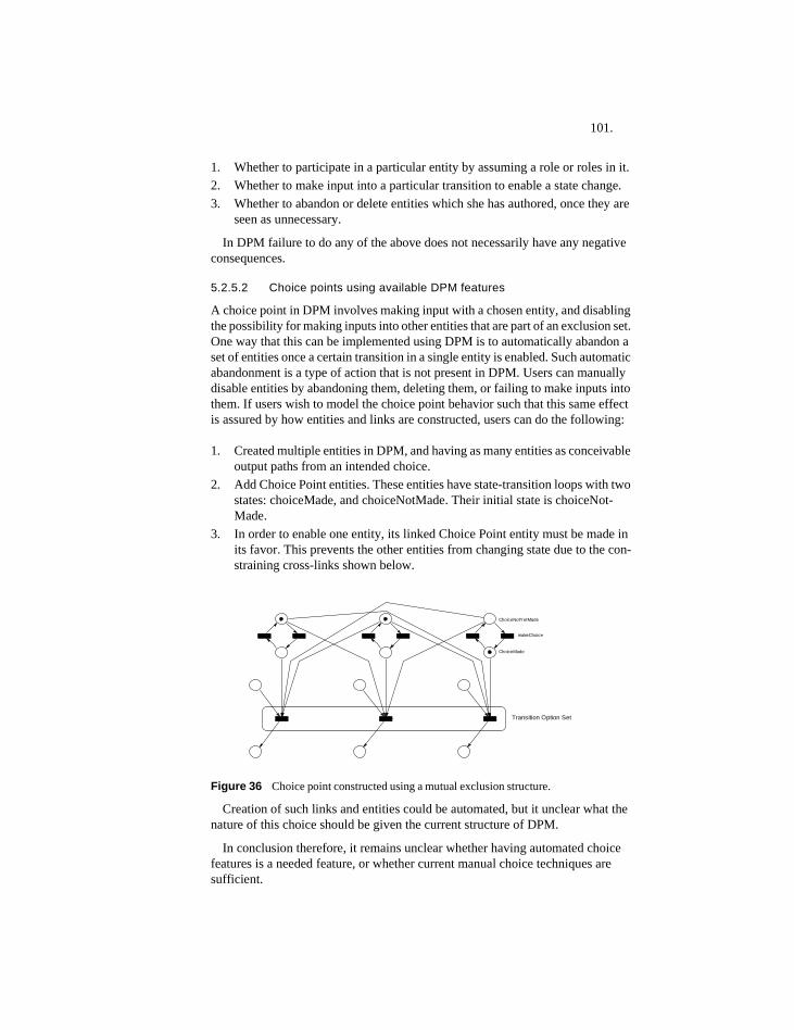
101.
1. Whether to participate in a particular entity by assuming a role or roles in it.2. Whether to make input into a particular transition to enable a state change.3. Whether to abandon or delete entities which she has authored, once they are
seen as unnecessary.
In DPM failure to do any of the above does not necessarily have any negative consequences.
5.2.5.2 Choice points using available DPM features
A choice point in DPM involves making input with a chosen entity, and disabling the possibility for making inputs into other entities that are part of an exclusion set. One way that this can be implemented using DPM is to automatically abandon a set of entities once a certain transition in a single entity is enabled. Such automatic abandonment is a type of action that is not present in DPM. Users can manually disable entities by abandoning them, deleting them, or failing to make inputs into them. If users wish to model the choice point behavior such that this same effect is assured by how entities and links are constructed, users can do the following:
1. Created multiple entities in DPM, and having as many entities as conceivable output paths from an intended choice.
2. Add Choice Point entities. These entities have state-transition loops with two states: choiceMade, and choiceNotMade. Their initial state is choiceNot-Made.
3. In order to enable one entity, its linked Choice Point entity must be made in its favor. This prevents the other entities from changing state due to the con-straining cross-links shown below.
Figure 36 Choice point constructed using a mutual exclusion structure.
Creation of such links and entities could be automated, but it unclear what the nature of this choice should be given the current structure of DPM.
In conclusion therefore, it remains unclear whether having automated choice features is a needed feature, or whether current manual choice techniques are sufficient.
ChoiceNotYetMade
ChoiceMade
makeChoice
Transition Option Set
102.
5.2.6 Security and privileges
5.2.6.1 Enable any user to contribute peergroups, roles, policies or inputs
Currently the application has no security in place other than the log-on procedure in JXTA that gives users secure users names and passwords, and enables them to access the JXTA system. This is basic level security and it applies to all JXTA-based applications.
Users of DPM also have the capability of creating peergroups and design entities, and adding roles, policies and inputs to these design entities. Additional security procedures could conceivably be put in place to handle all these types of user actions, to assure for instance that only qualified peers can make certain inputs and create certain types of objects.
What prevents chaos in the use of DPM is that normal social constraints can provide a degree of security. Peers when they make contributions, publish contributions in a semi-public forum. In design processes, reputations are important assets that designers usually work to protect. This is seen as a powerful constraining force, with the condition that the identity of those who provide inputs to the system are known to other users, at all times.
5.2.6.2 Possible security problems
1. Lack of authority or competence
Description: A user creates entities, signs up for roles, or defines policies for which they are unqualified to provide.
Discussion: Further work would be required to provide a system in which users could gain qualifications from some authority. In a distributed system it is not clear how to do this, or whether it is a desirable feature.
2. Masking of identity
Description: Someone uses the application pretending to be someone else.
Discussion: It is assumed that the basic security of JXTA, which requires login by all users, is sufficient to prevent this at a basic level.
3. Error in input
Description: User simply makes mistakes in the information they enter into the system.
Discussion: This is possible in all information systems in which input is not tested as it is entered. This is difficult since the information added in DPM is difficult to test for correctness, since its correctness depends on complex semantics. If users are not allowed to make anonymous inputs and are able to correct any mistakes, then it is assumed that other users will be able to spot and inform the user, such that mistakes can be corrected.
103.
4. Backtracking state changes
Description: Users participate in a state change that is later seen to be premature or erroneous and wish to undo the state change.
Discussion: In DPM, state changes go forward, but are not allowed to go backwards. The implicit assumption is that all inputs can only move an entity forwards. In order to generalize the act of making inputs to enable users to move an entity’s state backwards could be a useful feature for DPM. Other than the factor of possible complexity of implementing such a feature, the idea warrants future study.
5. Creation of false information
Description: A user inputs information into the system that does not correspond to any real design activity.
Discussion: This can be discouraged if users are not able to add information to the system anonymously, and are thus subject to peer disapproval if poor quality information is entered under their name.
6. Duplication of existing information
Description: A user unnecessarily duplicates information that already exists on the system.
Discussion: This is valid concern, and similar to simple errors and requires that if errors are spotted, it is possible for users to correct them.
7. Creation of contradictory, or deadlocking constraints
Description: A user constrains an entity in such a way that its state will never be able to advance.
Discussion: This is valid concern, and requires further work to create greater protection against this occurring.

104.
105.
6 Constructing process models by linking entities
6.1 IntroductionOne of DPM’s goals is to avoid excessive prescriptiveness in the manner in which the overall system operates, and in the types of semantic constructs that the support system provides the user. This avoidance of prescriptiveness is intended to make the system more flexible for a variety of users. Of course, avoidance of prescriptiveness has its dangers: if a system is truly non-prescriptive, then quite possibly it provides no guidance or support for its users.
In general there are two ways of supporting users in process support systems: 1. Build semantic constructs into the system, or 2. Enable users to build them, and then enable subsequent users to reuse them. The first approach could be called ‘prescription by design’, while the other ‘prescription by user behavior.’
The latter approach requires that users can be encouraged or motivated to build structures that later users might find useful or interesting. This approach is found in many P2P systems which usually have implicit design goals to maximize the opportunities for users to build unanticipated, emergent structures as a result of their distributed activity. The current research has been inspired by the promise of this approach.
The main mechanism that DPM uses in order to have prescriptions by user behavior available, is to use the distributed memory of past user actions, that resides in the P2P system. This memory records what users have used the system for in the past. The emerging contents of this memory are beyond the control of the software developer.
This use of memory of past actions is often fundamental to how P2P systems work at all: they are dependent on users actually using them in the past to make them useful for new users. This creates one of the most admirable qualities of P2P systems: how their performance can improve as their user base increases.
DPM uses prototypes based on either real entities or on aggregations of information from many entities. Prototypes serve as mechanisms to record organizational memory. A memory-based approach enables users to influence organization norms, and to affect how future users might use the software. Without using a system memory, every time a user builds new entities and structures, they start off at the beginning and are in effect ‘re-inventing the wheel.’
6.1.1 Information needs in Design
In the domain of design process management it is desirable to model the following:
106.
1. Representations of design projects, such that their participants can get the sense they are working on a common endeavor.
2. Places to store information related to design projects, including among other things, process representations that duplicate common task compositions, such as branch-in / branch-out constructs.
As detailed later in this chapter, the above entities can be constructed using the three main building blocks in DPM: hierarchical peergroups, design entities, and constraint links. Peergroups serve as virtual containers for information.
6.2 Hierarchical peergroups
6.2.1 Design projects as information containers
Design projects usually represent a contractually-defined business relationship between various people, either for a specific period of time, or until their work together is completed. This relationship is a dynamic entity in which people and information flow in and out during its life span. Therefore, a ‘design project as flexible container’ metaphor seems appropriate. This container can contain the following types of information: • people participating in the design project,• roles that people assume with their participation,• design-related tasks these people are expected to perform, to fulfill their
contractual obligations,• representations of the products that result from the design process, and• other types of miscellaneous information that might naturally accumulate during
a project such as meeting minutes, agreements, reports, etc.
DPM addresses the first three of these. It is unclear in general whether single, integrated applications should handle all these, or whether a suite of applications is more appropriate.
Many-to-many mappings can exist between these information representations, and the design projects of which they might be a part. For instance, designers might work on more than one project at a time, similar tasks might be used on different projects, and report formats and agreements might be re-used between projects. In professional design environments, designers may work on many projects simultaneously. They must be able to manage their time such that multiple projects are well coordinated, and that diverse types of commitments from many sources are dealt with in a timely fashion.
6.2.2 Uses for hierarchical peergroups
In DPM, there is no semantics attached to hierarchical peergroups other than the parent-child relation inherent in the hierarchical structure. This gives users the freedom to produce any kind of hierarchies they wish, since however users structure their peergroups, the DPM system is not affected. The behavior of links and entities does not depend on the particular peergroup in which they are situated.
107.
6.3 Design entity management
6.3.1 User defined types
In DPM users are allowed to provide type descriptions of the design entities they construct. In DPM all such entities are instances of ‘DesignEntity.’ These are similar to object types. For example a user can define the following entities: Course1: [TOI_Course], or Task1: [DesignTask]. The string within the square brackets indicates the entity type in DPM.
The major behavior of DesignEntities is to describe their current state. Since entities with different entity types don’t currently have differences in basic behavior, it makes no sense to implement them as different object types in Java.
What can distinguish a [TOI_Course] and a [DesignTask] is the state-transition loop, and the types of policy and link constraints that are connected to the DesignEntity. The full behavior of these user-named entities then becomes a combination of the process behaviors of DesignEntities, combined with the constraints that are attached to them. These policy and link constraints determine the dynamic behavior of design entities in DPM.
The use of prototypes in DPM, as explained below, enables what one user might design for one DesignEntity, to be reused when constructing another design entity of the same entity type.
Another approach is to enable users to define prototypes explicitly, and specify the types of state-transition loops to be used, and the composition of constraint links that would connect a new instance of the prototype to other instances of other prototypes. In this way, users could create complex configurations of linked entities quickly, all based on approved process policies.
However, it is not clear whether such an approach would be superior to the current approach based on dynamically generated prototypes. This issue requires future study and may be closely related to the nature of management policies of the enterprise in which DPM is used. In some enterprises process must be tightly controlled, while in others flexibility and ease of adaptation are more important.
6.3.2 Deletion and abandonment of entities
In DPM users can either delete objects of a few selected types, or can abandon DesignEntities, if they are its author. The delete action makes the object effectively disappear, while the abandon action notifies that the entity is no longer to be used, but keeps it around as a reminder for users.
Currently actions that authors can perform on an existing entity are: they can use them as provided, they can delete them, or they can abandon them. Other than that there is no editing possible of entities beyond that available when a user first creates an entity.
108.
6.3.2.1 Deletion of entities
A normal use case for users of computer applications is to both create, and to delete information. If users are free to create a type of object, then the same users generally have the opportunity to delete it as well. However, with distributed applications the process of deletion is problematic.
Distributed applications depend on the presence of distributed information for them to work. This entails information being communicated to, and saved by multiple peers. This redundancy of information gives distributed systems security and dependability. If one peer happens to be off-line one day, the information that resides on her computer is usually not inaccessible, since it may have been duplicated on other peers to which she is normally connected. With centralized server-based systems, if a server contains vital information, then operation of the system will depend on that server being available to all users at all times.
Creation of redundant information, which is a basic approach to data used in distributed systems, creates a problem when it comes to deleting information. Deletion is then a more complex issue than simply going to the centralized data store in which the information is kept and deleting it at its source.
6.3.2.2 Deletion approaches
One approach to deletion in distributed systems is to have an automated agent search for information to delete on all peers it discovers. This approach has the disadvantage of not working in peers that do not happen to be online while this agent does its work. It also means that peers must enable a destructive external agent to work with one’s own data store.
The approach used in DPM is not to search for information to delete, but rather to advertise the fact that some user has decided to delete a particular piece of information. The act of deletion then involves creating a deletion type of advertisement in DPM: a DeleteAdvertisement. This advertisement is then communicated to all other peers using JXTA’s data propagation techniques. This delete advertisement then becomes like any other kind of information communicated between peers in DPM. There is no guarantee that any one peer will receive it, but if a peer does, it prevents the object of that information from being displayed, communicated to other peers, or stored on the peer’s computer.
In this way, information is not actually deleted, it just becomes invisible to users. Once information becomes invisible in JXTA, it then dies a ‘natural death’ due to the temporal-based garbage collection system built into JXTA.
The current approach in DPM is to enable any users to delete a variety of object types including: Design Entities, Role Advertisements, Policy Advertisements, and PeerGroups.
6.3.2.3 Deletion policies within Wikis
A similar situation to DPM’s, with respect to deletion, occurs in the world of ‘wikis.’ A wiki is a collection of interlinked web pages, any of which can be visited
109.
and edited by anyone at any time from any place. The wiki concept and software were invented by Ward Cunningham (Wikimedia.org, 2004).
The Wikipedia is a collaborative project that has produced an extensive on-line wiki encyclopedia, in which any user—that is, anyone viewing its web pages—has edit and delete privileges. The Wikipedia has grown quickly, with fewer destructive deletions and editing than one might think. To manage this freedom requires various community-based control mechanisms that encourage thoughtful edits and non-anonymous deletions. Wikis are web-based and therefore depend on centralized web servers to operate. Wikipedia’s editors closely manage and review its content as it evolves. The basic wiki concept is therefore defined by its lack of security with respect to deletion and edits. Despite this user freedom, the world of wiki appears to be flourishing.
The one major constraint in DPM is that only the peer who originally authored information is able to delete it. Therefore there is less freedom to delete than found in any wiki. Alternatives to author-only deletion are conceivable, such as requiring that all those who have assumed roles must give their consensual agreement for an entity to be deleted. It is likely though that such policies would be impractical and overly bureaucratic in practice, and that the open policy of wikis might be most suitable in the long run.
6.3.2.4 Abandoning entities
To abandon means to signal to other users that an entity is no longer being used, yet the abandoned entity is still visible to users. Evidence of entities being abandoned is expected to be quite informative for historical purposes, as opposed to simply deleting entities and have them vanish instantly. As with deletions, the current rule is that only the author of an entity can abandon it. Once an entity is abandoned, its display icon changes and further state changes are prevented.
6.3.3 Iteration of entities
In DPM users are allowed to iterate entities. Once these entities reach the end of their ‘life cycle’ they can be reused. This involves making an entirely new entity using the previous one as a prototype. For example, if an entity is named courseA, after iteration it becomes courseA_2.
Therefore, iteration is the opposite of abandonment. The more iterations that an entity experiences, suggests greater success this entity has had in the real world. Abandonment implies that an entity has been found unsuited for continued survival.
6.3.4 Reuse of entities (using prototypes)
In DPM, when users create a new entity, they have available information that has built up from the use of the system—assuming the system has some user history. This information is based on design entity prototypes. These prototypes can either be natural prototypes based on real entities (usually the latest entity of that type created), or can be synthetic in that information is derived from attributes of many entities.

110.
There are two types of information currently derived from prototypes: policy constraints that apply to each transition in the entity’s state-transition loop, and the linked entities that affect how an entity changes its state in relation to other entities. These linked entities can be based on either incoming or outgoing links.
Different methods for deriving prototypes are selectable by user when they create new entities. User can set two variables: 1. The entity population selector for specifying the population from which a prototype is derived, and 2. A prototype algorithm that specifies the specific method for retrieving an entity from a particular population of entities. Therefore, the number of prototype retrieval methods is the Cartesian product of population selectors X prototype algorithms.
6.3.4.1 Current entity population selectors
1. ALL_PEERS (default): finds all entities authored by any user.2. THIS_PEER_ONLY: only finds entities that have been authored by the user.
6.3.4.2 Current prototype algorithms
1. LATEST (default): finds the most recent entity of a specific entity type, e.g. [DesignTask].
2. MOST_ACTIVE: finds the entity that has had the greatest number of state changes during its history.
3. SUM_OF_EXISTING: makes a logical sum of all information found for an entity of a particular entity type, from which the user can pick and choose. This type of prototypes is called ‘synthetic’ in that it is not based on any one entity, but on aggregated information from many entities. The usefulness of such an algorithm is dependent on the number of entities contained within the system.
6.3.4.3 Adding new prototypes
To add new prototype algorithms or population selectors is not a difficult task. Currently, only developers, not users, can perform these functions. Conceivable enhancements to this list could be population selectors, which consider only entities authored by members of specific peergroups, or by peers who have accumulated specific experience, or reputations within the system. In the meantime it is expected that using the defaults of ALL_PEERS combined with LATEST will be useful for most users.
6.3.4.4 Current limitation of prototypes
Prototypes are used to replicate only the links and linked entities that are directly linked to a prototype. Therefore, an entire chain of links is not recursively traversed and cloned.
Prototypes are based on entity type. For example, if a user is creating a new DesignTask, then only other DesignTasks are used to inform the prototype. In DPM there is no notion of emergent types—that is, types defined by the type of links or policies an entity has acquired.

111.
6.3.4.5 Bootstrapping needed at beginning
Prototypes only work if the system has a history of entities within it. At beginning of using the system, this is not the case. This ‘pre-historical’ stage of system use tends to be brief and be used for testing purposes.
When single users are using the system, as was the case during system development and testing, then the only existing cache of DPM data was on one computer that was not shared with other DPM peers. A tester in order to test the system in a ‘bootstrap’ situation, and to remove obsolete information can remove DPM’s JXTA cache manually.
DPM is a specialized type of JXTA application. Therefore, most of the information it shares with DPM peers is of a type that non-DPM peers will not be able to understand, despite working according to the JXTA P2P protocol. This means JXTA peers can make use of some of DPM’s information such as Peer and PeerGroup advertisements, but not with DPM advertisements such as DesignEntity advertisements, which are sub-classes of the JXTA class ‘Advertisement.’
Currently, DPM suggests standard state-transition loops and standard policies for each transition of an entity’s loop. This information is dependent on the type of loop selected by the user. When no prototypes can be found, simple policies for each transition of the entity are created. Links between entities will not be found in the system, since there are no existing entities to be found. Once entities exist in a user's local cache, then the following prototype-based objects are created:
1. Policies for each transition,2. Incoming and outgoing constraint links, and 3. Linked entities that are connected by these links.
6.3.4.6 Summary of prototype process
Whenever users are creating new entities, the entire history of the use of DPM is readily available—assuming the parts making up this history are available locally. This leverages its capabilities considerably and appears to make it more practical as a collaborative tool, since it records the history of past collaborations.
In the normal non-bootstrap condition, prototypes inform entity creation, since prototypes policies and linked entities are automatically included in the NewDesignEntity form. Users then just need to select those prototype-derived suggestions that they feel are appropriate. When designers are first modeling complex linked entities, it may require a lengthy modeling process at the beginning. Once that work is done however, it can be reused by anyone else.
Any information that a prototype does suggest can later be deleted. Therefore, entity creation in DPM is a risk-free process, which doesn’t lock the user into using any information that may later turn out not to be suitable for the entity.
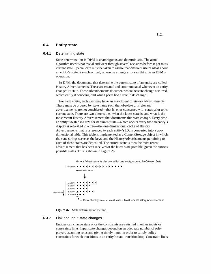
112.
6.4 Entity state
6.4.1 Determining state
State determination in DPM is unambiguous and deterministic. The actual algorithm used is not trivial and went through several revisions before it got to its current state. Special care must be taken to assure that different user’s ideas about an entity’s state is synchronized, otherwise strange errors might arise in DPM’s operation.
In DPM, the documents that determine the current state of an entity are called History Advertisements. These are created and communicated whenever an entity changes its state. These advertisements document when the state change occurred, which entity it concerns, and which peers had a role in its change.
For each entity, each user may have an assortment of history advertisements. These must be ordered by state name such that obsolete or irrelevant advertisements are not considered—that is, ones concerned with states prior to its current state. There are two dimensions: what the latest state is, and what is the most recent History Advertisement that documents this state change. Every time an entity is tested in DPM for its current state—which occurs every time an entity’s display is refreshed in a tree—the one-dimensional cache of History Advertisements that is referenced to each entity’s ID, is converted into a two-dimensional table. This table is implemented as a ContentStorage object in which the state strings serve as the keys, and the HistoryAdvertisements pertaining to each of these states are deposited. The current state is then the most recent advertisement that has been received of the latest state possible, given the entities possible states. This is shown in Figure 26.
Figure 37 State determination method.
6.4.2 Link and input state changes
Entities can change state once the constraints are satisfied in either inputs or constraints links. Input state changes depend on an adequate number of role-players assuming roles and giving timely input, in order to satisfy policy constraints for each transitions in an entity’s state-transition loop. Constraint links
Latest state
EntityID
0.State1.State2.State3.State4.State
History Advertisements discovered for one entity; ordered by Creation Date
Current entity state = Latest state X Most recent History Advertisement
Most recent
113.
depend on linked-in entities achieving a particular specified state, specified in the constraint link.
It is conceivable that an entity will lack both these types of constraints for a particular transition. Users can cause this simply by deleting all policy or link constraints from a transition. In order to prevent an entity changing state in a runaway fashion, DPM is currently configured to prevent such unconstrained state change.
6.4.3 Parallel vs. sequential processes in DPM
Parallel processes are ones that can work independently, while sequential processes depend on completion of one to enable progress of another. In DPM, parallel processes are ones that are not linked together by constraints links. This means they place no constraints on each other and lead independent lives.
A sequential process can be modeled using constraint links to constrain two entities together. This means that the preceding entity must reach its final state, before the subsequent entity’s first transition is enabled. Therefore, a preceding entity must be completed before the second entity can continue past its initial state. This is shown in Figure 42 below.
Users can also add constraints that do not require that the first entity reaches its final state but can reach any other state leading to the final state. Therefore, users can model sequences in which the preceding entity need not finish completely before the start of the subsequent entity.
6.4.4 Inputs seen as a type of voting system
DPM has a type of voting system in which assuming a role in an entity, registers the peer for little asynchronous ‘elections’ held at each transition. These elections depend on all registered voters actually voting, with the election choice being: can this entity advance its state? If ‘yes’, add an input, if ‘no’ do nothing.
Voters can provide their vote at any time, or can choose not to vote at all even after registering. These elections require 100% voter participation, and a unanimous ‘yes’ vote from all registered voters.
If a person assumes a role (registers to vote) and then doesn’t vote, this effectively deadlocks an entity’s state-change process. Therefore, once peers assume a role, there may be some peer pressure put on eligible voters to cast their votes in a timely fashion. Clearly this is an aspect of DPM that needs future work. Currently the only mechanism for exerting ‘peer pressure’ on users of DPM to provide timely input into entities is the text listing of inputs requiring user input, shown in the entity’s mouse-over label popup. A more pro-active mechanism would be helpful in DPM.
6.4.4.1 Conceivable voting enhancements
This unanimous consensus-based voting policy is rather strict and unforgiving, and may create deadlock, as peers assumes roles, but then forget to vote.
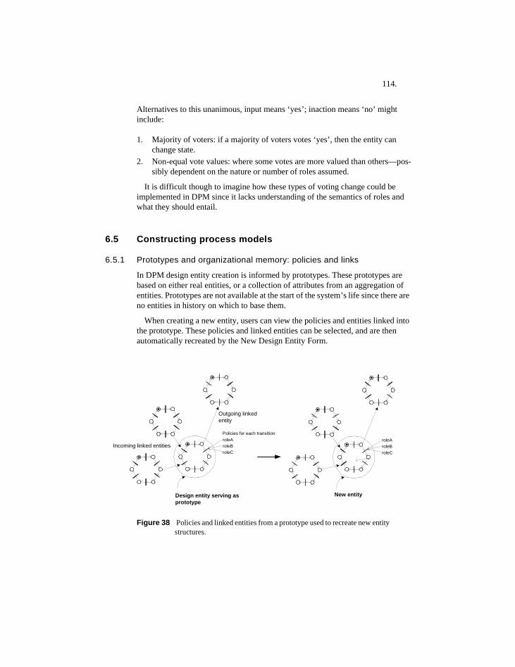
114.
Alternatives to this unanimous, input means ‘yes’; inaction means ‘no’ might include:
1. Majority of voters: if a majority of voters votes ‘yes’, then the entity can change state.
2. Non-equal vote values: where some votes are more valued than others—pos-sibly dependent on the nature or number of roles assumed.
It is difficult though to imagine how these types of voting change could be implemented in DPM since it lacks understanding of the semantics of roles and what they should entail.
6.5 Constructing process models
6.5.1 Prototypes and organizational memory: policies and links
In DPM design entity creation is informed by prototypes. These prototypes are based on either real entities, or a collection of attributes from an aggregation of entities. Prototypes are not available at the start of the system’s life since there are no entities in history on which to base them.
When creating a new entity, users can view the policies and entities linked into the prototype. These policies and linked entities can be selected, and are then automatically recreated by the New Design Entity Form.
Figure 38 Policies and linked entities from a prototype used to recreate new entity structures.
Design entity serving asprototype
Incoming linked entitiesroleAroleBroleC
Outgoing linkedentity
Policies for each transition:
New entity
roleAroleBroleC
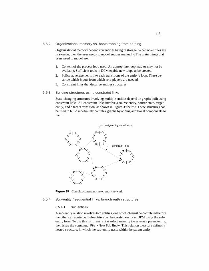
115.
6.5.2 Organizational memory vs. bootstrapping from nothing
Organizational memory depends on entities being in storage. When no entities are in storage, then the user needs to model entities manually. The main things that users need to model are:
1. Content of the process loop used. An appropriate loop may or may not be available. Sufficient tools in DPM enable new loops to be created.
2. Policy advertisements into each transitions of the entity’s loop. These de-scribe which inputs from which role-players are needed.
3. Constraint links that describe entities structures.
6.5.3 Building structures using constraint links
State-changing structures involving multiple entities depend on graphs built using constraint links. All constraint links involve a source entity, source state, target entity, and a target transition, as shown in Figure 39 below. These structures can be used to build indefinitely complex graphs by adding additional components to them.
Figure 39 Complex constraint-linked entity network.
6.5.4 Sub-entity / sequential links: branch out/in structures
6.5.4.1 Sub-entities
A sub-entity relation involves two entities, one of which must be completed before the other can continue. Sub-entities can be created easily in DPM using the sub-entity form. To use this form, users first select an entity to serve as a parent entity, then issue the command: File > New Sub Entity. This relation therefore defines a nested structure, in which the sub-entity nests within the parent entity.
design entity state loops
constraint links
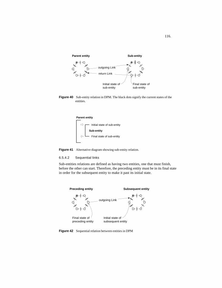
116.
Figure 40 Sub-entity relation in DPM. The black dots signify the current states of the entities.
Figure 41 Alternative diagram showing sub-entity relation.
6.5.4.2 Sequential links
Sub-entities relations are defined as having two entities, one that must finish, before the other can start. Therefore, the preceding entity must be in its final state in order for the subsequent entity to make it past its initial state.
Figure 42 Sequential relation between entities in DPM
Parent entity Sub-entity
Initial state ofsub-entity
outgoing Link
Final state ofsub-entity
return Link
Initial state of sub-entity
Final state of sub-entity
Parent entity
Sub-entity
Preceding entity Subsequent entity
Initial state ofsubsequent entity
outgoing Link
Final state ofpreceding entity
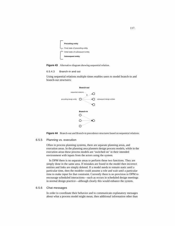
117.
Figure 43 Alternative diagram showing sequential relation.
6.5.4.3 Branch-in and out
Using sequential relations multiple times enables users to model branch-in and branch-out structures:
Figure 44 Branch-out and Branch-in precedence structures based on sequential relations.
6.5.5 Planning vs. execution
Often in process planning systems, there are separate planning areas, and execution areas. In the planning area planners design process models, while in the execution areas these process models are ‘switched on’ in their intended environment with inputs from the actors using the system.
In DPM there is no separate areas to perform these two functions. They are simply done in the same area. If mistakes are found in the model then incorrect entities and links are simply deleted. If a model needs to remain static until a particular time, then the modeler could assume a role and wait until a particular time to make input for that constraint. Currently there is no provision in DPM to encourage scheduled interactions—such as occurs in scheduled design meetings in normal design practice—although clearly this would enhance the system.
6.5.6 Chat messages
In order to coordinate their behavior and to communicate explanatory messages about what a process model might mean, then additional information other than
Preceding entity
Subsequent entity
Initial state of subsequent entity
Final state of preceding entity
preceding design entity
sequential relations
Branch-out
subsequent design entities
Branch-in
118.
entity structures are needed. Text messages are useful for coordinating group activity, and for adding information that may be difficult from possibly complex linked entity structures.
To add additional information, chat messages enable user to post messages to any peergroup. These can be open messages that appear for any user who displays the contents of the peergroups, or they can be private messages that only appear to particular users. Therefore, private messages are simply invisible to users other than the intended recipient.
6.5.7 Convergence in groups
Successful use of system like DPM depends not only on people building useful entity and peergroup structures, but also on the group coming to some consensus about how to approach design problems, and how to structure their processes.
The use of prototypes is the greatest factor in this respect, Using prototypes to aid in new entity construction, enables lessons learned from anyone using the system to influence how users create entities.
The second technique is to use text chat messages that are identified by their author and date to inform users of the system. Both prototypes and messages have been found to be necessary to make DPM useful in a distributed social context.
119.
7 Application testing and validation
7.1 Introduction to testingSoftware testing is the process of executing software and comparing the observed behavior to the desired behavior. This can be done both in the context of users of the software, and before the software gets into users’ hands. ‘Beta testing is typically conducted by end users of a software product who are not paid a salary for their efforts.” (Rivest, 2004)
It is impossible to develop software of any complexity without testing it during development. Every time a developer attempts to compile code, it involves performing a basic type of software test.
Ulrich Flemming writes, “...in the context of a Ph.D. thesis, time and financial constraints often limit the participants needed for tests to fellow students, a group that is often self-selected and not representative of the envisaged end-users. It is better to do this than forego testing altogether, but carefully designed experiments with end-users remain the gold standard for validation.” (Flemming, 2004).
A promising and sophisticated approach to software development is the ‘test first, implement later’ approach found in extreme programming (Extreme Programming Organization, 2004). The unit testing framework ‘JUnit’ enables developers to write unit tests, then enables developers to test code until it passes pre-written tests (JUnit Organization, 2004). The programming effort represented in this research unfortunately was not completed using JUnit. However, the author believes that automated unit testing is essential in taming the complexity of software development. The complexity of such development can grow quickly and go beyond that which is manually controllable, and manageable. Tools like JUnit are especially useful when requirements change at a late stage in software development—as they often do.
The goal of testing is not to confirm the obvious, but to learn from ‘interesting failures’ (Stellingwerff, 2004). Therefore, failure in a test is not an undesirable result. Failures can provide more useful information than can a successful test. Given the nature of the software, and the ill-defined nature of the domain to which it is applied, various types of failure are much more likely than success.
7.2 Introduction to TOITOI (Technisch Ontwerp & Informatica) is the institutional environment in which DPM was tested. It is the department that provides most of the computer-support related education for students and faculty within the Faculty of Architecture at TU Delft.
The chair of Technical Design and Informatics (TOI) develops comput-er-supported techniques and methods for design and construction in ar-
120.
chitectural design. The chair provides education at the bachelor and mas-ters levels in construction technology, architecture, and urban design, us-ing ICKT (Information, Communication and Knowledge Technology) as a tool, medium, and partner, for integration, cooperation, and communi-cation of design processes (TOI, 2004).
7.3 TOI and student processesThe beginning classes of the architectural program (BSc1 and BSc2) have well-defined milestones that students are expected to fulfill over time. The order and structure of these milestones is fixed, however, students have considerable freedom in deciding when they complete each milestone. Therefore, a student’s process is based on her individual progress, rather than on a pre-set course schedule navigated by groups of students within a class block. Due to the educational course structure of the faculty, students are at various stages within these processes.
It is difficult both for students and administration staff to know if a student has finished all courses, submitted all assignments, or is in the process of re-sitting examinations. Keeping track of such information in TOI is difficult, and consumes considerable managerial and computational resources.
Therefore, BSc1 and BSc2 are like state machines, in which, if students progress past well-defined milestones, they can continue on with their studies. It is often difficult to manage students’ progress through this process, since each student may be at a slightly different stage within it. The testing within TOI involves keeping track of a student’s ‘state’ within TOI processes.
TOI has evolving, difficult-to-manage processes. These processes involve from the student perspective of taking courses, handing in assignments, and writing and passing examinations. These processes involve many actors, such as students, TOI support staff, professors, teachers, graders, etc. They also involve turn-taking interactions between actors. For example, when a student submits assignment, then TOI staff must grade the assignment submitted.
7.3.1 Overall nature of these processes
TOI processes can be quite complex in practice, due to several factors:• The unlimited time period students have to fulfill some requirements.• The dynamic nature of the course offerings by TOI. These involve many
different types of courses, taught by a large number of teachers at various times.• The large numbers of students who are required to take the courses offered by
TOI.• The transient population of student employees of TOI, who do much of the work
in providing backup to TOI’s courses, and in coordinating with students regarding their current state and remaining course requirements.
These factors make course processes difficult to manage within TOI. They also provide motivation to explore alternatives to current management systems. For
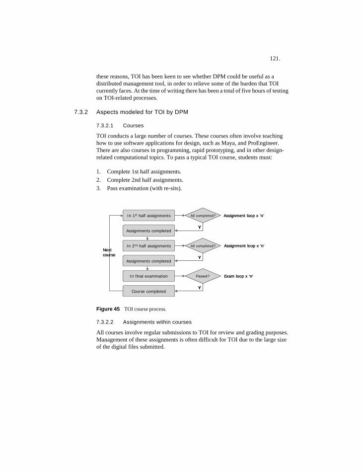
121.
these reasons, TOI has been keen to see whether DPM could be useful as a distributed management tool, in order to relieve some of the burden that TOI currently faces. At the time of writing there has been a total of five hours of testing on TOI-related processes.
7.3.2 Aspects modeled for TOI by DPM
7.3.2.1 Courses
TOI conducts a large number of courses. These courses often involve teaching how to use software applications for design, such as Maya, and ProEngineer. There are also courses in programming, rapid prototyping, and in other design-related computational topics. To pass a typical TOI course, students must:
1. Complete 1st half assignments. 2. Complete 2nd half assignments.3. Pass examination (with re-sits).
Figure 45 TOI course process.
7.3.2.2 Assignments within courses
All courses involve regular submissions to TOI for review and grading purposes. Management of these assignments is often difficult for TOI due to the large size of the digital files submitted.
In 1st half assignments
Assignments completed
In 2nd half assignments
Y
All completed?
Assignments completed
Y
All completed?
In final examination
Y
Passed?
Course completed
Nextcourse
Assignment loop x ‘n’
Assignment loop x ‘n’
Exam loop x ‘n’
In 1st half assignments
Assignments completed
In 2nd half assignments
Y
All completed?
YY
All completed?
Assignments completed
Y
All completed?
YY
All completed?
In final examination
Y
Passed?
YY
Passed?
Course completed
Nextcourse
Assignment loop x ‘n’
Assignment loop x ‘n’
Exam loop x ‘n’
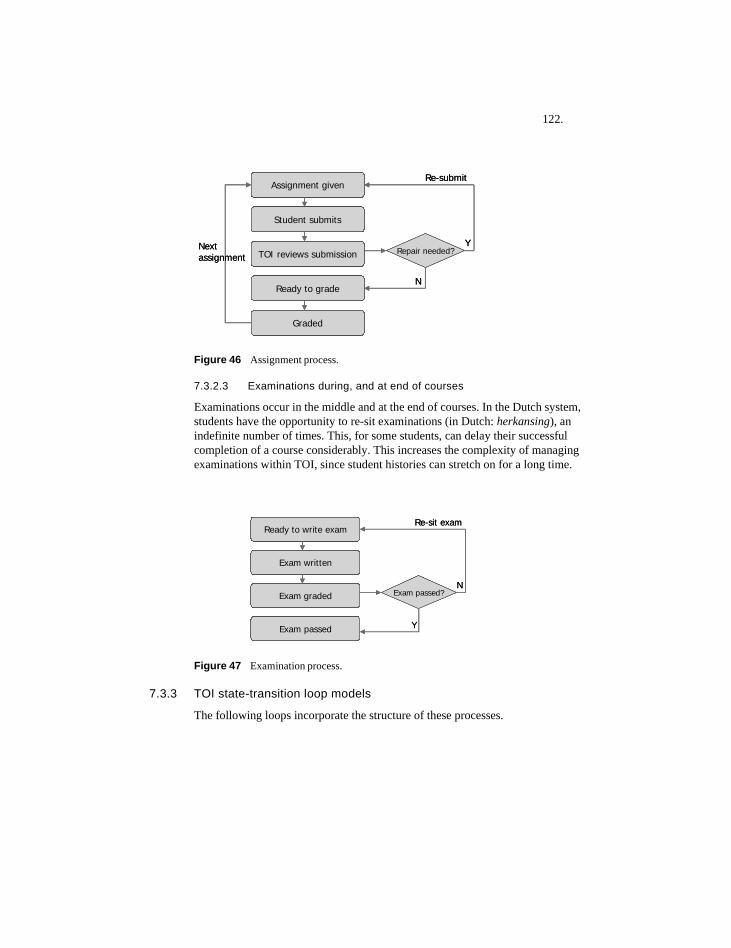
122.
Figure 46 Assignment process.
7.3.2.3 Examinations during, and at end of courses
Examinations occur in the middle and at the end of courses. In the Dutch system, students have the opportunity to re-sit examinations (in Dutch: herkansing), an indefinite number of times. This, for some students, can delay their successful completion of a course considerably. This increases the complexity of managing examinations within TOI, since student histories can stretch on for a long time.
Figure 47 Examination process.
7.3.3 TOI state-transition loop models
The following loops incorporate the structure of these processes.
Assignment given
Student submits
TOI reviews submission Repair needed?
Ready to grade
Graded
N
Y
Re-submit
Next assignment
Assignment given
Student submits
TOI reviews submission Repair needed?
Ready to grade
Graded
N
Y
Re-submit
Next assignment
Ready to write exam
Exam written
Exam graded Exam passed?
Exam passed Y
N
Re-sit examReady to write exam
Exam written
Exam graded Exam passed?
Exam passed Y
N
Re-sit exam
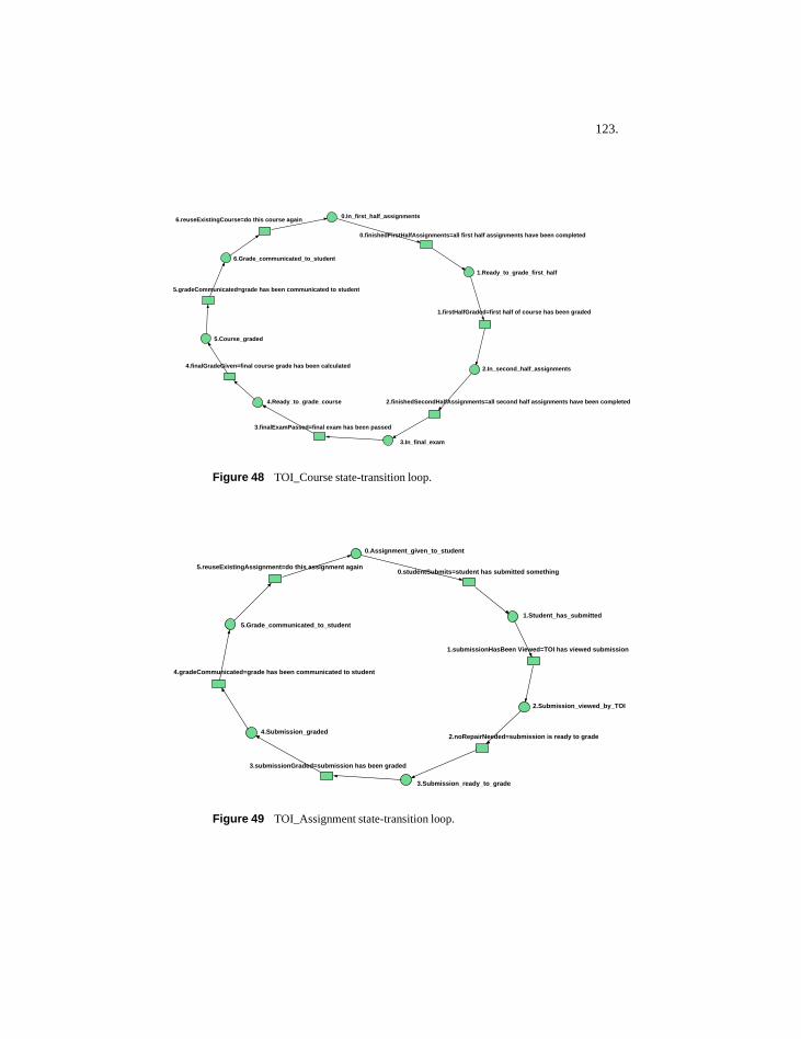
123.
Figure 48 TOI_Course state-transition loop.
Figure 49 TOI_Assignment state-transition loop.
0.finishedFirstHalfAssignments=all first half assignments have been completed
3.finalExamPassed=final exam has been passed
4.Ready_to_grade_course
4.finalGradeGiven=final course grade has been calculated
5.gradeCommunicated=grade has been communicated to student
6.reuseExistingCourse=do this course again
2.finishedSecondHalfAssignments=all second half assignments have been completed
2.In_second_half_assignments
1.firstHalfGraded=first half of course has been graded
3.In_final_exam
5.Course_graded
6.Grade_communicated_to_student
0.In_first_half_assignments
1.Ready_to_grade_first_half
5.reuseExistingAssignment=do this assignment again0.studentSubmits=student has submitted something
1.Student_has_submitted
1.submissionHasBeen Viewed=TOI has viewed submission
2.Submission_viewed_by_TOI
2.noRepairNeeded=submission is ready to grade
3.Submission_ready_to_grade
3.submissionGraded=submission has been graded
4.Submission_graded
4.gradeCommunicated=grade has been communicated to student
5.Grade_communicated_to_student
0.Assignment_given_to_student
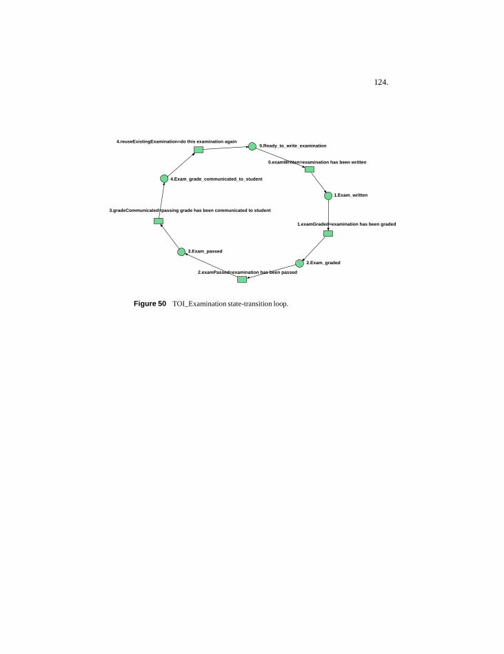
124.
Figure 50 TOI_Examination state-transition loop.
0.examWritten=examination has been written
1.examGraded=examination has been graded
2.Exam_graded
2.examPassed=examination has been passed
3.gradeCommunicated=passing grade has been communicated to student
4.Exam_grade_communicated_to_student
3.Exam_passed
1.Exam_written
0.Ready_to_write_examination4.reuseExistingExamination=do this examination again
125.
7.4 Test specificsTests of DPM should answer the following basic questions:
1. Does the application work as advertised?2. Does the performance of the application degrade excessively when confront-
ed with large amounts, and possibly contradictory data, from multiple users?3. What insights does the application suggest for the planning and management
of collaborative design processes?4. What does testing suggest as being the most promising or appropriate direc-
tion for future work?
The goal, as with all testing, is to maximize the chance that anomalies are discovered during the testing period, such that they can be eliminated before the application is put into wider circulation. Therefore, successful tests are considered ones in which anomalies are found. As with any testing, finding no errors does not necessarily mean that the software is error-free.
7.4.1 Pre-test tasks
Some preparation and setup work is required before tests can be conducted:
1. Briefing the TOI department about the general research concepts that have in-formed the design and implementation of DPM, and how DPM could be suit-able as a tool to manage processes within TOI, as well as form a topic for fur-ther research.
2. Assembling a pool of testers interested in learning about DPM, and distribut-ed P2P applications in general. Training this pool about how DPM operates such that they have sufficient knowledge about how DPM operates to perform the tests.
3. Installing DPM on several testers’ machines. Some testers had single instanc-es of DPM, while others had multiple instances. Multiple instances involved having a tester assuming multiple peer names, and that separate instances of DPM ran from separate directories on the tester’s computer. The software in-stallation process involved giving testers a single executable called: ‘dpm.exe’ If Java is properly installed on the machine, double-clicking on this executable will start DPM. For new users this opens the JXTA configuration tool. For return users, a user-defined password is required to gain access to DPM.
126.
7.4.2 Test 1: Basic functionality of DPM
7.4.2.1 Description
Tests whether DPM functions properly at its basic level.
7.4.2.2 Participants
Four student assistants from the TOI department, Faculty of Architecture, TU Delft.
7.4.2.3 Venue
TOI computer lab, 6th floor, Architecture Building at TU Delft.
7.4.2.4 Duration
Over two days in November 2004. Total test time: 2 hours.
7.4.2.5 Tasks to be performed by each tester
1. Join the DPM network and establish a peer identity that is visible to other us-ers of DPM. How this is done is covered in the Appendix: Instructions for in-stalling Design Process Modeler (DPM).
2. Create several sample hierarchical peergroups. To create a new peergroup:2.1 Select a peergroup node to serve as the parent.2.2 Issue the menu command: File > New Peergroup.2.3 Enter a new peergroup’s name in the form that opens.2.4 Repeat this multiple times to create a peergroup hierarchy, with at least
three branches, and at least three levels deep.2.5 Once such a peergroup hierarchy is created, exit DPM and see if it still
exists when DPM is opened again.
3. See if peergroups created are visible to other peers:3.1 This requires that testers work in pairs, or in groups, and manually ob-
serve whether peergroups are communicated successfully between peers.
4. Join and leave peergroups:4.1 Select a peergroup node and issue the command: Peergroup > Join Peer-
group.4.2 See if the peer is added to the peergroup. Also, see if this membership is
communicated to other peers. 4.3 Repeat this process by leaving by issuing the command: Peergroup >
Leave Peergroup.
5. Create design entities of various entity types and communicate these entities to other DPM peers.5.1 Select a peergroup node to serve as the parent peergroup.
127.
5.2 Issue the menu command: File > New User Named Entity.5.3 Create several sample TOI_Courses, TOI_Assignments, and
TOI_Examinations.
6. Set up policy constraints for design entities: (Note: policy constraints are specifications regarding which roles are needed for a design entity to advance its state).6.1 Select a design entity.6.2 Issue the menu command: File > New Policy.6.3 Add test roles to each transition: e.g. TOI_Grader. If such a role is not
present in the list, then manually enter this role name. 6.4 See if these policy constraints have been added: select the entity they
were added to, then issue the menu command: Entities > Show Input Policy (All Transitions). The newly added policies should be visible.
7. Add link constraints between design entities:7.1 Select a design entity, e.g. a TOI_Course, to serve as a parent in a sub-
entity relation.7.2 Issue the menu command: File > New SubEntity Link.7.3 In the form that opens, select an entity to serve as a child, e.g.
TOI_Assignment. This child entity then must be completed before its parent can be completed.
7.4 Select the target transition of the sub-entity link. In the SubEntity form, this is shown as: ‘Completion of Child required to enable this transition of <parent name>.’ For TOI_Courses, an appropriate transition to select is: ‘0.finishedFirstHalfAssignments.’ The intended meaning of this sub-entity relation is that a number of TOI_Assignments must be completed for a student to complete the first half assignments of a TOI_Course.
7.5 Do this multiple times for each required TOI_Assignment.
8. Assume roles in entities:8.1 Roles in design entities means that the peer can effect state changes. If a
role assumed matches a policy constraint, then this peer can block an en-tity from changing state until that user makes an input into that entity. A user assumes a role by doing the following:
8.2 Select a design entity.8.3 Issue the menu command: File > New Role.8.4 In the form that opens, enter the name of the new role by selecting an item
from the list in the form, or adding a new term.8.5 Check to see if the role has been added, by putting the mouse over an en-
tity and viewing the popup label that displays: ‘Your roles....’
9. Observe state changes of these entities, constrained by both their policy and link constraints.
128.
9.1 State changes in design entities are enabled by either: 1. Adding inputs to satisfy policy constraints, or 2. Having incoming link constraints satisfied by having the incoming linked entity attain the state that is specified in the constraint link. For example, for sub-entity or sequential relations, ei-ther the sub-entity or the preceding entity must be at their final states, which is the last state found in their loop model—that is, the state with the largest number prefix.
9.2 The loop that an entity uses is listed in the entity’s popup label. If the user opens the ‘loopNets’ peergroup folder, all the states and transitions for each loop can be seen in each loop’s popup label (made visible by placing the mouse pointer over the loop).
9.3 If an entity has no constraints, then DPM is currently configured not to allow state changes. In detailed process models, design entities can have a complex mix of both link and policy constraints.
9.4 Add inputs to satisfy policy constraints to assure that incoming entities are in an appropriate state to enable link constraints. View whether DPM changes the entity’s state automatically and whether these state changes are communicated to other peers.
10. Deletion and abandonment of entities.10.1In DPM, users can create, delete, and abandon entities. Users can also de-
lete a number of other objects that are shown in the ‘Edit’ menu. These include: loop nets, links, messages, peergroups, and policy constraints.
10.2Testers should attempt to create each of these delete-able objects, and then delete them. This is done by selecting each item, then issuing the menu command: File > Delete <x>.
10.3Design entities can also be abandoned. This means they are still visible, but state changes are no longer possible. Abandoned entities have a cross icon that distinguishes them from normal entities.
10.4Select a design entity, then issue the menu command: Edit > Abandon En-tity. See if entities are also abandoned on others peers’ systems (this may require a refresh of the tree in which they are displayed. Double-clicking on the peergroup node does this.
7.4.2.6 Criteria for above tests
1. Effort of setting up peer accounts.1.1 Is the setup procedure easy for users of DPM?1.2 Can installation and setup of DPM be more automated, and thus avoid
novice users having to make decisions to get rendezvous and relay peers?
2. Reliability and synchronization of information communicated between peers, including entity attributes, and entity states.2.1 If a peer creates an object in DPM, do other peers receive it?
129.
2.2 Can the latency period between creating information and its propagation to other peers create corrupted information in DPM?
3. User comprehension of domain concepts such as: entities, entity types, and roles, and constraints.3.1 Are the basic domain concepts of DPM difficult for users to understand?
4. Reachability of peers behind possible firewalls, using JXTA relays or proxies.4.1 Do some peers have more difficulty than others in receiving DPM infor-
mation?
5. Ability to create peergroups hierarchies containing various types of informa-tion.5.1 Are current peergroup tree mechanisms easy to use?
6. Performance of DPM in common tasks.6.1 Is DPM responsive enough for common user actions?
7. Ability of users to return to DPM and find information in predictable loca-tions.7.1 Should peergroup trees appear the same way each time a user opens them
up, down to their lowest leaves?

130.
7.4.3 Test 2: Error production tasks
One way to see if software works is to attempt to produce errors. Testers should purposely attempt to create the following error situations:
1. Register as a peer in DPM, then not have your peer identity visible to other peers. • Note: this should not be possible in JXTA (unless no other DPM peers are
on-line), even if the peer is behind a firewall. Being behind a firewall re-quires special configuration of JXTA by specifying a proxy server.
2. Create hierarchical peergroups that are not navigable for other peers.• Note: very deep peergroup trees can possibly create non-navigable peer-
groups. Deep tree hierarchies also assumed that each chain in the tree struc-ture is communicated to all peers. Deep hierarchies must be opened one tree level at a time in DPM.
3. Create design entities that are not visible to other peers.• Note: This should not be possible other than the short latency period re-
quired to propagate information between peers in JXTA. This latency may be several minutes, depending on peer location and network configuration, and is similar to the time that email messages take to travel to their recipi-ents.
4. Have an entity attain a state that is not the same as the same entity’s state as shown on another computer. • Note: Correct synchronization of entity states between peers, is a funda-
mentally important aspect of DPM.
5. Add policy, and link constraints that are not communicated to others.• Note: this should not be possible in JXTA, unless no other DPM peers are
on-line.
6. Omit all constraints from an entity and see if its state changes (it shouldn’t).
7. Omit all policy constraints from an entity, and but include several link con-straints, and attempt to create state changes by making the incoming entities attain the state specified in the link constraint. See if this produces errors.
8. Omit all links constraints from an entity, and but include several policy con-straints, and attempt to create state changes by adding inputs to an entity. See if this produces errors.
9. Attempt to create deadlocked constraints that are impossible for peers to re-move—that is, ones that forever prevent a design entity from advancing its state.
131.
7.4.4 Test 3: Integration test
7.4.4.1 Description
Tests whether DPM can be used as a process support tool for use in TOI course-related processes. These processes deal with a student’s state of progress within the BSc-level courses that TOI offers. DPM is intended to be a tool that could be useful both for TOI’s as well as each student’s informational needs. Currently such information is managed manually, using student lists and spreadsheets. The principal objects used within these processes are: TOI_Courses, TOI_Assignments, and TOI_Examinations. State-transition loop models customized for these TOI processes are available in the current version of DPM.
7.4.4.2 Participants
Six student assistants from the TOI department, Faculty of Architecture, TU Delft.
7.4.4.3 Venue
TOI computer lab, 6th floor, Architecture Building at TU Delft.
7.4.4.4 Duration
Over three days in November 2004. Total test time: 2 hours.
7.4.4.5 Tasks to be performed by each tester
1. Peergroup structure to be completed by testers altogether:1.1 Space for 30 students taking 3 TOI courses each.1.2 Each course (per student) would have: 1 TOI_Course entity, 5
TOI_Assignment entities, and 1 TOI_Examination entity (which can be repeated an indefinite number of times).
2. Each tester will assume the role of several students, in order to test a reason-able number of participants. The goal is to create 30 test student accounts in total. With six testers, this involves each tester assuming five different student roles. When configuring DPM to run several instances on the same computer, if this is necessary, care must be taken to specify correctly, and remember, passwords, user names, and port numbers. One method of doing this that has proved workable is:2.1 Copy the DPM executable to five separate directories on your computer.2.2 Have one term that identifies: the tester, and the peer number, and the
password. For example, if ‘michaelC’ is to test five different peers by in-stalling DPM five times on the same computer, then one approach is to set:• Peer Names as: michaelC01, michaelC02, michaelC03, etc.• Secure User Names as: michaelC01, michaelC02, michaelC03, etc.• Passwords as: michaelC01, michaelC02, michaelC03, etc.
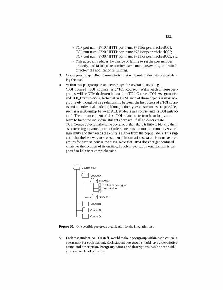
132.
• TCP port num: 9710 / HTTP port num: 9711for peer michaelC01;TCP port num: 9720 / HTTP port num: 9721for peer michaelC02;TCP port num: 9730 / HTTP port num: 9731for peer michaelC03, etc.
• This approach reduces the chance of failing to set the port number properly, and failing to remember user names, passwords, or in which directory the application is running.
3. Create peergroup called ‘Course tests’ that will contain the data created dur-ing the test.
4. Within this peergroup create peergroups for several courses, e.g. ‘TOI_course1’, TOI_course2’, and ‘TOI_course3.’ Within each of these peer-groups, will be DPM design entities such as TOI_Courses, TOI_Assignments, and TOI_Examinations. Note that in DPM, each of these objects is most ap-propriately thought of as a relationship between the instructors of a TOI cours-es and an individual student (although other types of semantics are possible, such as a relationship between ALL students in a course, and its TOI instruc-tors). The current content of these TOI-related state-transition loops does seem to favor the individual student approach. If all students create TOI_Course objects in the same peergroup, then there is little to identify them as concerning a particular user (unless one puts the mouse pointer over a de-sign entity and then reads the entity’s author from the popup label). This sug-gests that the best way to keep students’ information separate is to make peer-groups for each student in the class. Note that DPM does not get confused whatever the location of its entities, but clear peergroup organization is ex-pected to help user comprehension.
Figure 51 One possible peergroup organization for the integration test.
5. Each test student, or TOI staff, would make a peergroup within each course’s peergroup, for each student. Each student peergroup should have a descriptive name, and description. Peergroup names and descriptions can be seen with mouse-over label pop-ups.
Course tests
Course A
Course D
Course B
Course C
Student A
Student B
Entities pertaining toeach student
133.
6. Each student who takes this course would join the peergroup, using the menu command: Entities > Join Peergroup. Note that the join action must be done by each peer himself or herself. In DPM currently, it is not possible for a user to join a peergroup on someone else’s behalf.
7. Simulate a course scenario with the following overall process:7.1 A student joins an existing course, or a member of the TOI staff, sets up
the course structure for the student.7.2 All ‘stakeholders’ in each student’s progress—normally the student her-
self, and several members of TOI (say, instructor, and grader) will join each student’s peergroup for each course. It is not clear that this is the best way to approach such a problem. To DPM, it matters little how de-sign entities are arranged, or in which peergroups they are situated. But for users, as explained above, it can make a large difference.
7.3 Create multiple assignments for each course, with variable constraints on completion. See when particular assignments are most suitable due with-in the course structure, such as within the first half of the course, or sec-ond half, etc. How the course is structured overall is reflected in the con-tent of the state-transition loop model. For example, if courses have a first half and a second half, then this organizational fact can be embedded into the loop model. This suggests that customized loop models will evolve to reflect different course structures.
7.4 Work through state changes for each entity for each student, such that each student attains a final state such as:• 1. Student successfully completes the course. • 2. Student completes the course work but must repeat the final exami-
nations several times.• 3. Student withdraws from the course without completing it.• 4. Student fails the course and must withdraw from it.
7.5 View the history of course changes. This is viewed by selecting a design entity, then using the menu command: Entities > Show Entity History. This panel shows the complete state change history of the entity.
134.
7.4.4.6 Criteria
1. Suitability for TOI’s processes.1.1 Are there any advantages in using DPM over current TOI information
systems?1.2 Does DPM provide a new type of information, or does it duplicate infor-
mation that is already available within TOI?1.3 Can TOI users create suitable places to put information using DPM?1.4 Do different users put information in similar places?1.5 Is the granularity of information suitable for what students and TOI need
to manage their processes?1.6 Is DPM able to adapt to changing processes within TOI?
2. Entities in DPM.2.1 Is the concept of ‘User Named Entity’ clear to users?2.2 Is the process of attaching loop state models clear to users?2.3 Is having an entity in a particular state significant to users?2.4 Do users add inputs when it is suitable for them to do so?
3. Roles in DPM.3.1 Do users comprehend roles and their meanings?3.2 Do users continue to create new roles—that may duplicate the meaning
of previously used ones?3.3 Do roles acquire generally accepted meanings that are clear to users?
4. Quality of information provided4.1 Is information provided by DPM reliable and accurate—that is, do users
trust the information that DPM provides?4.2 Is information provided by DPM secure?
135.
7.5 Testing results
7.5.1 Things that worked well during testing
7.5.1.1 State change mechanisms
State change mechanisms work as intended. This is one of the fundamental aspects of the DPM system. This applies to both input-based, and to link-based state change mechanisms.
7.5.1.2 Synchronization of information
Either information was not available at all, or it tended to be correct. There was no evidence of obvious discrepancies of entity state.
7.5.1.3 Prototype system
The prototype system creates new entities based on the history of ones created in the system. The current dynamic approach appears to be suitable for the task. There was little discussion of the prototype system, since it did not figure prominently in the tests. There was no demand for other types of prototype systems, such as explicit modeling of prototypes and storing these as models in the system.
7.5.2 Things worked less well during testing
7.5.2.1 Performance
Performance when used in a group setting was at first poor. Each DPM instance consumes an increasing amount of memory, suggesting a memory leak. The leading theory to explain this is that as users search for content within peergroups, new threads are created in DPM, which appear to multiply and consume increasing resources. The effect of this poor performance is that simple actions take too long, or fail to happen at all within a reasonable period. The solution to this major problem was to:• examine the code to see where memory leaks might occur, • profile the application using Java profiling tools, to see if certain components
use excessive resources, and • create more coherent thread policies, such that resource-hungry threads are
turned off when not needed. These things were all done and performance of DPM has improved substantially. See the section below: ‘Revisions to software after testing.’
7.5.2.2 Reliability of communication of basic information
For the first round of testing, information was not reliably transmitted between users, such that users received information created by fellow testers. After revision of the software reliability was improved. However, some sources of reliability problems are not simple implementation errors in the software that can be easily
136.
improved, but are related to the basic nature of P2P software. These are discussed below.
7.5.2.3 Complexity of whole concept
As mentioned above, the basic concept of DPM is complex and difficult for testers to comprehend at first. It is unclear during testing whether this can be solved by either educating the tester more thoroughly, or whether the fault lies with the basic approach taken by the application. It is also unclear whether the basic terminology used by DPM: roles, policies, inputs, peergroups trees, are as simple and straightforward as they could be.
7.5.2.4 Poor visibility of process structures
Users of DPM can create complex linked entity structures. To view these structures, users must leave the main DPM window, which shows the contents of various peergroups organized into tree nodes, and open another window in which links (both constraint and information) are shown as trees. In future versions of DPM, a more integrated approach, in which this information is shown in the main window, or perhaps one that is less tree-based, and more graph-based, might be appropriate.
7.5.2.5 Difficulty in configuration
JXTA Configuration requires manually setting port numbers, and specifying other options that are not necessarily relevant or interesting to users—especially testers. This occurs when users first become peers on a JXTA network, and uses a tool within JXTA called the Configurator. If testers need to configure multiple instances of DPM on their machine, as occurred during testing, different port numbers for each DPM instance must be set. This is annoying and is error-prone since it is easy to forget to do this task. If not done then DPM does not communicate information between peers correctly.
JXTA Configuration can be automated, and set programmatically in the latest version of JXTA. This means specification of ports, relays, rendezvous addresses, etc. can be done without involving the users. The next version of DPM will incorporate this feature.
7.5.2.6 Steep learning curve of basic concepts
DPM combines concepts from both P2P computing as well as Petri net technologies. In order to do a thorough job, in which users are not confused by how DPM works, then they should have some foundation in both these subjects. This is difficult to do in a test situation, in which there is seldom time enough to do this well.
With Petri nets, a little demonstration can go a long way in giving people an intuitive understanding in how states and transitions interact to form state machines. A live graphical demonstration of a simple loop Petri net showing a model of how DPM design entities will work as distributed process models is necessary in future to give users and testers a sufficient understanding of Petri net
137.
concepts to be able to use the application quickly. Perhaps such a visual demonstration could be built into the application itself.
7.5.3 Safety in testing vs. usability of distributed systems
During testing, there tends to be few users, since having many testers (say dozens or more) is harder to manage, and is less safe. During testing, large errors could be discovered in the software, DPM could begin to consume excessive network bandwidth (as did Napster), or it could be seen as a malicious virus (Fortunately, none of these things have yet occurred.) Such things could conceivably harm the computer network of the Architecture Faculty, and make popularization of DPM problematic. Therefore, it is preferable to limit possible damage during testing (before wide-scale roll-out of DPM) by limiting the number of testers.
One important aspect of P2P computing is with more users performance of the system usually increases. With few users, overall performance of the system remains low. Therefore, safety in testing, and creating a workable distributed information system, work at cross-purposes. For safety, limiting initial testers is desirable, but for creating workable P2P systems, increasing the number of testers is desirable.
7.5.4 Bootstrapping of peergroups
When a peergroup is first created, the user who creates it is the only peer who is aware of its existence, and knows about possible resources the peergroup might contain. For other users to acquire this information, they must first discover the peergroup, and then make another discovery request for the contents of the peergroup. If the original author of the peergroup does not happen to be online when the second discovery request is made, then it is likely that the request will not be answered, and the peergroup’s contents will be invisible to other users.
One work-around for this problem is synchronize the usage of DPM by peers who are working together. They could do this by agreeing to have DPM on at the same time, such that information about peergroups of common interest is exchanged reliably between the cooperating peers. This however, is quite limiting. Ideally, users of DPM should not have to synchronize their work patterns in any way with other peers—even those with whom they are working together on a common design entity. P2P should lend support for asynchronous work, such that peers can make contributions whenever they want.
7.5.5 Transmission of data between peers
In JXTA, information is communicated within peergroups. When there are many users in these peergroups, communication of information within them tends to be more successful. With many users, information is duplicated in users’ local caches and tends to be reliably available to other users. If all users are on-line all of the time, then they will tend to get all the information that is to be had within the peergroups they have open. However, this is not usually the case. Users often open DPM for a short time and then close it. This limits the number of local user caches that information can dwell in and live to be communicated to other users.
138.
Information is published (or broadcast) in DPM when information is first created. It is then published locally and remotely by DPM—using the JXTA methods publish()and remotePublish()respectively. If peers are open at the time, then they receive this information. However, if peergroup trees have too few members, then it is probable that this new information is communicated only into the local cache of the information’s author.
The best-case scenario for reliable communication in DPM is when: 1. users always have DPM open and online, 2. peergroups have more than one or two members, 3. There are direct connections, with few network hops between users. In such a case, communication of information between users of DPM happens within seconds. This is the case in a normal test situation. The responsiveness of the system may not be as immediate as a client-server system, but seems adequate.
The least reliable scenario is when: 1. use of DPM by its users is sporadic, 2. peergroup have solitary members, and 3. users are separated from one another by many network hops. In this scenario information may simple never arrive to its intended or potential audience. This seems to more approximate the real-world usage of DPM before it is widely distributed and used.
Information can also be re-broadcast in DPM either manually or automatically. Re-broadcasting involves taking all the information found locally by a user in a particular peergroup, and re-publishing it within the scope of the peergroup. Tests demonstrated that re-broadcasting of information, takes many seconds and appears to consume excessive bandwidth. It does communicate information reliably between users when one user can view some information and another user cannot.
However, it is not the case that by assuming the performance penalty of re-broadcasting really solves the reliability problem. Re-broadcasting suffers from the same basic problem as does the original publishing process: there is no guarantee that there will be an audience for the re-broadcasted information, if too few peers are in a position to receive this information.
Re-broadcasting is now viewed as a work-around for actions that should be done automatically and transparently in JXTA and DPM. The preferred approach is for information to be published only when it is first created in DPM. It is not clear whether re-broadcasting is necessary in cases where peergroup member populations are small, or whether other mechanisms in JXTA, which may not be known to the author, can be used to achieve the same effect.
7.5.6 Peergroup size and information specificity
Increasing the number of peers with an interest in a peergroup tends to make it more reliable. However, this tends to make the peergroup less specific to particular student’s needs. For example, it is beneficial to make peergroups that concern single students, since in this way students can have all the information that concerns them in one spot. However, this means that only the student, some worker in TOI and perhaps a few others will ever have any interest in instantiating this peergroup, and discovering what it might contain.
139.
Therefore, a compromise might have to be made: make peergroups large enough so they involve a lot of people, but don’t make them so large that the information they contain covers too many subject matters. Like the option of synchronization work patterns in DPM, this requirement is limiting. Ideally users should not have consider what the optimal membership size of peergroups should be, since this is hard to predict, depends of factors outside of the user’s control such as network topologies, and therefore places an unwelcome burden of users.
The main factor related to optimal peergroup size is the usage patterns of DPM users: whether they use DPM all the time, or whether they only use it sporadically. With sporadic use, optimal peergroup size would be much larger than with constant use. Additional real-world testing would be required to gain more idea of what an optimal peergroup size would be, if such a thing exists. Ideally, of course, any peergroup size should function as well as any other.
7.5.7 Revisions to software after testing
The two main aspects that proved problematic during testing were: 1. excessive and increasing consumption of computing resources by DPM, and 2. the reliability of communication of essential information between users, such as new entities and entities states.
7.5.7.1 Reduction of resource consumption
After preliminary testing, DPM was profiled using the NetBeans Profiler (NetBeans, 2004). This tool can analyze resource consumption of various parts of a Java application. The main consumer of resources, in a part of DPM that was easily reconfigurable, was the method by which remote peergroup searching threads were created. By minor changes to this code, the resource consumption problems in DPM were alleviated.
Before testing, when users created a new peergroup node, they would instantiate a peergroup advertisement, then create a thread which sent out a remote discovery requests every thirty seconds to all peers who are members of the peergroup. Remote peers could then respond to these requests and send back newly discovered peergroup resources to be included in a peergroup’s display. These threads would continue running until the user switched them off. As users created more peergroup nodes these threads would multiply and consume increasing resources. Quickly, this process made DPM unusable.
The revised approach is now not to create new threads that search for remote resources, but simply to create a single discovery request for remote resources, after refresh of the node, which reflects the latest content of the local JXTA cache. This solved the DPM performance problem. The revised node refresh code is shown below:
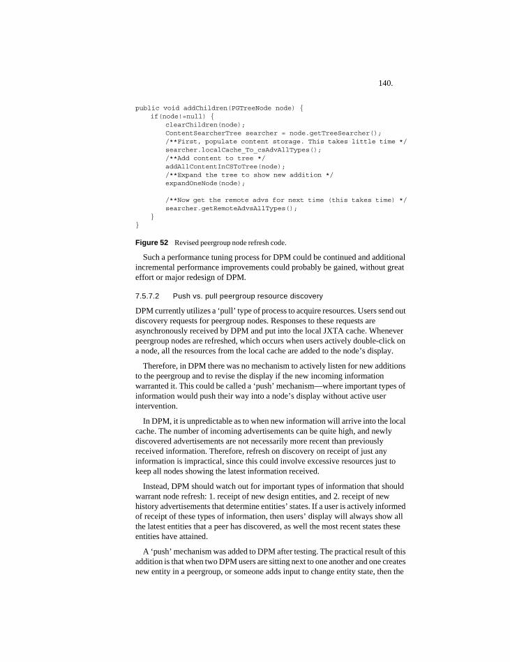
140.
public void addChildren(PGTreeNode node) {if(node!=null) {
clearChildren(node);ContentSearcherTree searcher = node.getTreeSearcher();/**First, populate content storage. This takes little time */searcher.localCache_To_csAdvAllTypes(); /**Add content to tree */ addAllContentInCSToTree(node);/**Expand the tree to show new addition */expandOneNode(node);
/**Now get the remote advs for next time (this takes time) */searcher.getRemoteAdvsAllTypes();
}}
Figure 52 Revised peergroup node refresh code.
Such a performance tuning process for DPM could be continued and additional incremental performance improvements could probably be gained, without great effort or major redesign of DPM.
7.5.7.2 Push vs. pull peergroup resource discovery
DPM currently utilizes a ‘pull’ type of process to acquire resources. Users send out discovery requests for peergroup nodes. Responses to these requests are asynchronously received by DPM and put into the local JXTA cache. Whenever peergroup nodes are refreshed, which occurs when users actively double-click on a node, all the resources from the local cache are added to the node’s display.
Therefore, in DPM there was no mechanism to actively listen for new additions to the peergroup and to revise the display if the new incoming information warranted it. This could be called a ‘push’ mechanism—where important types of information would push their way into a node’s display without active user intervention.
In DPM, it is unpredictable as to when new information will arrive into the local cache. The number of incoming advertisements can be quite high, and newly discovered advertisements are not necessarily more recent than previously received information. Therefore, refresh on discovery on receipt of just any information is impractical, since this could involve excessive resources just to keep all nodes showing the latest information received.
Instead, DPM should watch out for important types of information that should warrant node refresh: 1. receipt of new design entities, and 2. receipt of new history advertisements that determine entities’ states. If a user is actively informed of receipt of these types of information, then users’ display will always show all the latest entities that a peer has discovered, as well the most recent states these entities have attained.
A ‘push’ mechanism was added to DPM after testing. The practical result of this addition is that when two DPM users are sitting next to one another and one creates new entity in a peergroup, or someone adds input to change entity state, then the

141.
other user’s peergroup display is automatically updated to reflect this newly created information.

142.
143.
8 Conclusion
8.1 Discussion of results
8.1.1 Role of P2P
One of the most interesting points of discussion were the questions during the TOI testing of DPM was ‘why use P2P’? This concerned the general suitability of P2P systems for information systems. In the domain used for testing—student processes within the TOI, there was little compelling advantage for using such a system since, from a user/tester’s perspective:
1. information may not as reliably transmitted between users as would a client-server system, and
2. trustworthiness and freshness of some data can be low when there is low peer-group membership.
Such problems can be avoided by adopting a client-server architecture, but then new problems are introduced, such as the effort and cost required to design and maintain client-server systems, and the concentration of processing loads and security issues inherent to centralized systems.
P2P is both an implementation technology, as well as an approach to self-organizing social and technical processes. This research co-mingles both of these aspects. In some domains, if P2P is seen purely as an implementation technology, there may be insufficient reasons to adopt it. It is unclear whether P2P has actually reduced the number of lines of code for this research, since the client-server alternative was not implemented (the author feels it probably has). However, if the goal is also to explore whether distributed process-support applications can be designed that structure processes in a formalized manner, then the P2P aspect of the research goes beyond being merely an implementation decision. It has been shown that a distributed implementation for design process coordination is workable—though not problem-free.
8.1.2 Aspects impaired by P2P
Access to all information at all times: communication of information in P2P is dependent on number of users in general, and on the membership of peergroups. Low user numbers lead to low performance in P2P systems. This results in lower reliability of information, and doubts in users whether the information that some peers can access is all the information that exists.
It is not clear that P2P implementations are well suited for supporting small groups of people who may not want to share information with larger populations of users. Unfortunately, small design teams—the most common kind—can usually be described as small groups of people who do not want to share information

144.
(often secret and proprietary) with just anyone. However, it is not clear that this constitutes a fatal flaw in the technology with respect to collaborative design applications.
8.1.3 Aspects helped by a P2P implementation
1. Avoidance of ‘global’ information: in a client-server system it is easy to store information that applies to all other users. In a P2P implementation such in-formation can be stored within the application itself—for instance the inclu-sion of a number of basic state-transition loops for use by TOI testers. If the goal is to enable peers to self-organize, then there is much less opportunity in P2P implementations to ‘cheat’ and introduce behind-the-scenes prescrip-tions. Yet, it is also clear that the boundary between what prescriptions devel-opers add to P2P applications, and what users self-organize on their own, is still quite ambiguous.
2. Probability of scalable performance: in the event that DPM is used by large numbers of users, then its performance should improve as information is dis-tributed and duplicated between peers.
3. Distribution and installation of the software is easy: all that is required of po-tential users or testers is to download the DPM software, have Java installed on the computer (which is usually the case), and double-click on an execut-able.
4. Maintenance and security safe-guarding of a server is not required. 5. All development can happen locally on a single machine without having to
gain access to a server. The development process then is centered on use of Java and of JXTA code. This proved straightforward to manage.
8.1.4 Solution to the reliability problem?
Testing of DPM shows that a degree of user synchronization of DPM is currently necessary. This is to avoid the problem of having information communicated within the scope of peergroups, without having sufficient members within these peergroups to store and transmit this information to other peers. What then are the possible solutions to this problem?
1. Have all peers store all information regarding all peergroups on their comput-ers. Comment: this works against the spirit of P2P computing and imposes centralized loads on every peer. P2P systems are built to distribute loads, which is why in JXTA information is shared within the limited scope of peer-groups.
2. Have all users do all their work in limited numbers of peergroups. Comment: If all users did all their work in one peergroup then the reliability problem would be solved. This would also tend to centralize loads onto each user. It also would prevent users from structuring information into smaller catego-ries—which currently in DPM is achieved through construction of peergroup hierarchies.
145.
3. Separation of information hierarchies from peergroup hierarchies. Comment: this appears promising and may be worthy of further study, however, peer-groups seem to be the natural approach in P2P of creating specialized places to put information.
4. Transfer information directly between peers rather than within peergroups. Comment: this also appears to be a promising direction. in JXTA, peers can create virtual pipe connections between individual peers such that informa-tion can be directly transferred along the pipe. This requires that both peers be online at the time. It is not clear whether this solve the problem of when two peers, who are directly interacting, are not online at the same time.
5. Have users synchronize their work patterns. Comment: This synchronization might involve only having DPM on when other users are likely to use it. This constraint is similar to client-server systems where in order to have reliable service for clients, the server is assumed to be always on and available to cli-ents. Having to synchronize usage adds an unwelcome and limiting constraint but may be necessary in cases when small number of users are working to-gether on shared information that will, at the best of times, interest only small numbers of people.
6. How so many users that information is duplicated and shared widely. Com-ment: this is the normal approach in P2P computing and assumes that reliabil-ity comes through increased numbers of users. For many domains, such as music sharing or distributed file systems, this approach has proven effective. It is unclear whether collaborative design processes will necessarily have suf-ficient user populations to make this approach always reliable.
8.1.5 Interactive nature of DPM’s process
DPM is an interactive system. It requires participation from many people for it to work as intended. For this participation to occur, the tool must provide useful information for all parties. In DPM’s case, in the context of the TOI department at TU Delft, this means it must satisfy information needs both of TOI as well as its students.
Therefore, in DPM’s case this means that the process of determining a student’s state within the educational process of TOI, is not solely up to TOI, but also up the students as well. Both the student and TOI personnel function as ‘peers.’ This is quite different in basic approach to current information systems at TOI. Since all role-players in DPM are not defined in any way that distinguishes them according to their role in the administration of TU Delft, this tends to blur the roles and rank of those who use DPM. It may not be clear to users if a role-player has a role of authority in the institution, or not. This is not necessarily always a good thing. In this way DPM tends not to be seen as a tool that has been imposed by the administration onto students. Rather it is a collaborative tool that requires cooperation and mutual participation.

146.
8.1.6 Leveraging external technologies
8.1.6.1 The technology of Petri nets
DPM depends on the technology of Petri nets. As it turned out, this process of modeling loops in Petri net form appears to be a process best left to the author. It appears that such modeling is beyond the interests and capabilities of the ordinary user. The concept of how a Petri net model is constructed and operates is not completely self-evident. Talk of states and transitions is technical and can be confusing for some. The fluent use of DPM depends on a greater understanding of how Petri nets work than expected.
8.1.6.2 Leverage of JXTA
Development of DPM involved leveraging basic JXTA capabilities within a custom domain. This approach relies on JXTA working as advertised. DPM therefore is dependent on future versions of JXTA for it to evolve and grow. This appears not to be a problem, since the developer community using JXTA is strong and is growing.
8.1.6.3 Role of the Java language
Java has been a significant and relatively recent development in computing technology, is now largely taken for granted. Java’s basic approach, and the ease of use of using an integrated development environment (or IDE—specifically NetBeans 3.6) made this research relatively easy to implement.
Standardization towards UML graphical representation of project structures (as used in the TogetherSoft IDEs) is seen as a further improvement towards implementation ease and power, using the Java language.
147.
8.2 Contributions
8.2.1 Implementation of a working prototype for design coordination
This research involved design and implementation of a working software prototype. This prototype demonstrated that a distributed P2P approach to the description and coordination of collaborative design processes is workable. The implementation phase of the research was extremely useful for attaining sufficient knowledge of P2P technologies to make a balanced assessment of the technology, as well as providing countless opportunities to investigate various approaches to collaborative processes and social interactions.
8.2.2 Provision of a process coordination framework
DPM enables users to participate in a structured coordination process that involves roles, and collaborative specification of entity state. DPM also enables users to communicate task, task dependency, and actor dependencies for tasks, in a low-cost, non-prescriptive manner. This enables distributed designers to coordinate their work on a real-time basis.
8.2.3 Interactive collaborative modeling tool
DPM enables distributed users to model not only design entities and their contents, but also to build hierarchies of peergroups. These peergroups enables users to browse collaboratively defined information structures, to see who else has joined these groups, and to see what kind of information exists within them. This information includes both design entities of various kinds as well as simple chat messages that users can post to hierarchical peergroups in a ‘blog’ fashion. Online collaboration can take place by simply exchanging information in simple message form, as opposed to the more complicated process of becoming involved in design entities and assuming roles in them.
8.2.4 Environment to represent and establish organizational norms
In DPM organizational norms are defined by the content of process loop models, as well as the type of constraints and linked entities that are created. Using the prototype feature that in DPM is built into the process of creating new entities, enables users to learn quickly about how others are using the system and to adjust their behavior correspondingly.
DPM depend on group of people creating histories of working together and to see histories of collaborations between various peers assuming a variety of roles. This process of producing a visible common, collaborative history is of great importance in structuring collaborative work.
8.2.5 Building of user-configured online teams
Enables users to build online teams and other types of communities quickly, using minimal software. This is a result of DPM leveraging the capabilities of JXTA—a sophisticated open-source P2P framework.
148.
8.3 Future research agenda
8.3.1 Increase the reliability of information transfer
As detailed above there are ways of possibly improving the reliability of information transfer, without corrupting the basic P2P approach and its benefits. This process could involve investigating whether peers could hold information about peergroups they may not have a direct involvement in, but have an interest in storing for other peers, without going so far as having all peers hold information about every peergroup found in the whole system. Use of pipe connections that would directly connect peers should also be investigated.
8.3.2 Build more sophisticated prototype mechanisms
The manner in which prototypes are found or created in DPM is in fact fundamental to its operation, although the testing process barely touched on this aspect. It is the mechanism in which group activity is encouraged to converge towards user-defined organizational norms. Greater study is required to see how this process works exactly and whether more sophisticated prototype algorithms could enhance it.
8.3.3 Explore information persistence
DPM up to now has had little study in how the life spans (or ‘time to live’) of design entities created in DPM should be manipulated to best effect. Distributed systems depend on distributed objects created within them having limited life spans. If objects do not have limited life spans, then the distributed system is soon choked with obsolete information.
It is expected that some information should never become obsolete and should endure in process histories for a long time. It is also expected that users should not be able to set life spans manually, since they lack sufficient knowledge of the issues involved to do it well. The consequence of doing it badly is that the distributed system could soon become unusable.
It is unclear what the criteria for setting life spans should be. Presumably, this life span setting process should be an emergent process that depends on how users make use of existing information. It should also be a process that is transparent to the user.
8.3.4 Simplify the process of modeling process loops
Currently, modeling using Petri net models is cumbersome for users. It is unclear how to make this process easier. It appears that most users simply lack a background in process representation techniques, and therefore must be exposed to this technology and its concepts quickly when exposed to DPM for the first time. The basic Petri net-based technology of the DPM approach has been of fundamental importance in providing distributed process models that peers can create, modify and run. Therefore, the basic technical foundation of DPM will remain Petri net-based.
149.
9 References
Aalst, W. v. d., Basten, T., Verbeek, H., Verkoulen, P., & Voorhoeve, M. 1999, August. Adaptive Workflow: An Approach Based on Inheritance Proceedings of 16th. Interna-tional Joint Conference on Artificial Intelligence. M. Ibrahim & B. Drabble Eds. Stock-holm, Sweden. 36-45.
Action Technologies. 1998. Business Process Integrity in ActionWorks. Action Technolo-gies Inc. Available: www.actiontech.com.
Agre, P., & Chapman, D. 1989. What are plans for? A.I. Memo 1050a. Cambridge, MA: Artificial Intelligence Laboratory, MIT.
Akin, Ö. 1986. Psychology of Architectural Design. London, UK: Pion.
Akin, Ö. 1991. A structure and function-based theory for design reasoning. In N. Cross & K. Dorst & N. Roozenburg Eds. Research in Design Thinking. Delft, Netherlands: Delft University Press.
Akin, Ö., Sen, R., Donia, M., & Zhang, Y. 1995. SEED-Pro: Computer-Assisted Architec-tural Programming in SEED. Journal of Architectural Engineering. vol.1. No.4. 153-161.
American Institute of Architects. 1994. Architects Handbook of Professional Practice. Washington, DC: AIA.
AngeloPeerRendezvous. 2004. AngeloPeerRendezvous: p2p-based software for intra-en-terprise communication. Available: http://angelopeerrendezvous.jxta.org/servlets/Pro-jectHome [2004, August 2].
Axelrod, R. 1997. The Complexity of Cooperation: Agent-Based Models of Competition and Collaboration. Princeton, NJ: Princeton University Press.
Bach, K. 1995. Speech act theory. In R. Audi Ed. Cambridge Dictionary of Philosophy. Cambridge, UK: Cambridge University Press.
Biberstein, O., & Buchs, D. 1998. An Object-oriented Specification Language based on Hi-erarchical Algebraic Petri Nets. Available: http://lglwww.epfl.ch.
Bijker, W. 1995. Of bicycles, bakelites, and bulbs: toward a theory of sociotechnical change. Cambridge, MA: The MIT Press.
Blazewicz, J., Ecker, K., Pesch, E., Schmidt, G., & Weglarz, J. 1996. Scheduling Computer and Manufacturing Processes. Berlin: Springer Verlag.
Boehm, B., & Hansen, W. 2001. The Spiral Model as a Tool for Evolutionary Acquisition. Crosstalk: The Journal of Defense Software Engineering. May. 4-11.
Bowker, G., & Star, S. L. 1999. Sorting Things Out: Classification and its Consequences. Cambridge, MA: The MIT Press.
Brooks, R. 1991. Intelligence without Representation. Artificial Intelligence. 47. 139-160.
Bucciarelli, L. L. 1994. Designing Engineers. Cambridge, MA: The MIT Press.
Bucciarelli, L. L. 2003. Engineering Philosophy. Delft, Netherlands: DUP Satellite, Delft University Press.
150.
Canadian Architectural Councils. 1995. Canadian Handbook of Practice for Architects: RAIC, and Committee of Canadian Architectural Councils. Ottawa: Royal Architectural Institute of Canada.
Carmichael, D. 1989. Construction engineering networks: techniques, planning, and man-agement. New York, NY: John Wiley & Sons.
Chomsky, N. 1969. Aspects of the Theory of Syntax. Cambridge, MA: The MIT Press.
Cindio, F. d., Michelis, G. d., & Simone, C. 1992. The Communication of Disciplines of CHAOS. In D. Marca & G. Bock Eds. Groupware: Software for Computer-Supported Cooperative Work. Los Alamitos, CA: IEEE Computer Society Press.
Clancey, W. 1993. Situated Action: A Neuropsychological Interpretation Response to Vera and Simon. Cognitive Science. No.17. 87-116.
Clancey, W. 1997. Situated Cognition: On Human Knowledge and Computer Representa-tions. Cambridge, UK: Cambridge University Press.
Clark, H. H. 1996. Using Language. Cambridge, UK: Cambridge University Press.
Coalesce. 2004. Coalesce: A seedbed for growing ideas. Available: http://coalesce.jxta.org/servlets/ProjectHome [2004, August 2].
Coyne, R., Rosenman, M., Radford, A., & Gero, J. 1987. Innovation and Creativity in Knowledge-Based CAD. In J. Gero Ed. Expert Systems in Computer-Aided Design. Am-sterdam: Elsevier.
Cross, N. 1993. Science and Design Methodology: A Review. Research in Engineering De-sign. vol.5. 63-69.
Cross, N., Christiaans, H., & Dorst, K. 1996. Introduction: The Delft Protocols Workshop. In N. Cross & H. Christiaans & K. Dorst Eds. Analysing Design Activity. Chichester, UK: John Wiley & Sons.
Cross, N., & Cross, A. C. 1996. Observations of Teamwork and Social Processes in Design. In N. Cross & H. Christiaans & K. Dorst Eds. Analysing Design Activity. Chichester, UK: John Wiley & Sons.
Cuff, D. 1991. Architecture: The story of practice. Cambridge, MA: The MIT Press.
Cumming, M. 2003, 26-30 July 2003. Sharing knowledge within organizational hierarchies using flexible peergroups Proceedings of 10th ISPE International Conference on Concur-rent Engineering: Research and Applications. J. Cha & R. Jardim-Gonçalves & A. Steiger-Garção Eds. Madeira, Portugal. 591-598.
Cumming, M., Akin, Ö., & Donia, M. 1998. SEED-Pro Tutorial Manual Unpublished soft-ware manual. Pittsburgh, PA: School of Architecture, and Institute for Complex Engi-neered Systems, Carnegie Mellon University.
Darke, J. 1984. The Primary Generator and the Design Process. In N. Cross Ed. Develop-ments in Design Methodology. New York, NY: John Wiley & Sons.
Donia, M., Flemming, U., Akin, Ö., Sen, R., & Cumming, M. 1998. SEED-Pro Reference Manual Unpublished software manual. Pittsburgh, PA: School of Architecture, and Insti-tute for Complex Engineered Systems, Carnegie Mellon University.
Dym, C., & Levitt, R. 1991. Knowledge-Based Systems in Engineering. New York, NY: McGraw-Hill.
Ennis, C., & Gyeszly, S. 1991. Protocol Analysis of the Engineering Systems Design Pro-cess. Research in Engineering Design. vol.3. 15-22.
Evan, W. 1993. Organizational Theory: Research and Design. New York, NY: Macmillan.
151.
Extreme Programming Organization. 2004. Extreme Programming: A gentle introduction., [Web site]. extremeprogramming.org. Available: http://www.extremeprogramming.org/index.html [2004, August 2].
Fenves, S., Flemming, U., Hendrickson, C., Maher, M. L., Quadrel, R., Terk, M., & Wood-bury, R. 1994. Concurrent Computer-Integrated Building Design. Englewood Cliffs, NJ: Prentice Hall.
Fenves, S., & Rivard, H. 2004. Generative Systems in Structural Engineering Design Pro-ceedings of GCAD '04: Generative CAD Systems Symposium. Ö. Akin & R. Krishna-murti & K. P. Lam Eds. Carnegie Mellon University, Pittsburgh, PA.
Fenves, S., Rivard, H., Gomez, N., & Chiou, S. 1995. Conceptual Structural Design in SEED. Journal of Architectural Engineering. vol.1. No.4. 179-186.
Ferber, J. 1999. Multi-agent Systems: An introduction to distributed artificial intelligence. Harlow: Addison-Wesley.
Ferraro, A., & Rogers, E. 1997. Petri Nets in the Evaluation of Collaborative Systems Pro-ceedings of The 1997 IEEE International Conference on Systems, Man, and Cybernetics Orlando, FL.
Flemming, U. 1998. SEED-Layout Tutorial Unpublished software tutorial. Pittsburgh, PA: School of Architecture, and Institute for Complex Engineered Systems, Carnegie Mellon University.
Flemming, U. 2004. Computer-aided architectural design: looking back, looking forward Proceedings of GCAD '04: Generative CAD Systems Symposium. Ö. Akin & R. Krish-namurti & K. P. Lam Eds. Carnegie Mellon University, Pittsburgh, PA.
Flemming, U. 2004. Keynote address: Computer-aided Architectural Design: Looking back, looking forward Proceedings of GCAD '04: International Symposium on Genera-tive CAD Systems. Ö. Akin & R. Krishnamurti & K. P. Lam Eds. School of Architecture, Carnegie Mellon University, Pittsburgh, PA.
Flemming, U., Aygen, Z., Burrow, A., Chan, T. W., Chien, S.-F., Chiou, S., Choi, B., Cum-ming, M., Datta, S., Donia, M., Drogemuller, R., Erhan, H., Fenves, S., Garrett, J., Go-mez, N., Johnstone, J., Han, K., Moustapha, H., Ozkaya, I., Rivard, H., Sen, R., Snyder, J., Tsai, J., Woodbury, R., & Zhang, Y. 2000. The SEED Experience Unpublished Tech-nical Report prepared at the end of the SEED contract for: US Army Corps of Engineers Construction Engineering Research Laboratory (USACERL). Pittsburgh, PA: School of Architecture, and the Institute for Complex Engineered Systems (ICES), Carnegie Mel-lon University.
Flemming, U., & Chien, S.-F. 1995. Schematic Layout Design in the SEED Environment. Journal of Architectural Engineering. vol.1. No.4. 162-169.
Flemming, U., & Chien, S.-F. 1998. SEED-Layout Reference Manual Unpublished soft-ware manual. Pittsburgh, PA: School of Architecture, and Institute for Complex Engi-neered Systems, Carnegie Mellon University.
Flemming, U., & Woodbury, R. 1995. Software Environment to Support Early Phases in Building Design (SEED): Overview. Journal of Architectural Engineering. 1. 4. 147-152.
Flores, F., Graves, M., Hartfield, B., & Winograd, T. 1992. Computer Systems and the De-sign of Organizational Interaction. In D. Marca & G. Bock Eds. Groupware: Software for Computer-Supported Cooperative Work. Los Alamitos, CA: IEEE Computer Society Press.
152.
Genesereth, M., & Fikes, R. 1992. Knowledge Interchange Format, Version 3.0 Reference Manual Logic-92-1. Stanford, CA: Computer Science Department, Stanford University.
Gong, L. 2001. JXTA: A Network Programming Environment. IEEE Internet Computing. 5. 88-95.
Gordon, D. 1999. Ants at Work: How an Insect Society is Organized. New York, NY: The Free Press.
Gorti, S., Gupta, A., Kim, G., Sriram, R., & Wong, A. 1998. An object-oriented represen-tation for product and design processes. Computer-Aided Design. vol.30. No.7. 489-501.
Guindon, R. 1990. Designing the Design Process: Exploiting Opportunistic Thoughts. Hu-man-Computer Interaction. vol.5. 305-344.
Hafner, K. 2001, January 18, 2001. Web Sites Begin to Self Organize, [Newspaper article]. Available: http://www.nytimes.com/2001/01/18/technology/18SELF.html?pagewant-ed=1&ei=5070&en=571d62b7ace54095&ex=1094702400.
Harel, D. 1988. On Visual Formalisms. Communications of the ACM. vol.31. No.5. 514-530.
Hendrickson, C., & Au, T. 1989. Project Management for Construction. Englewood Cliffs, NJ: Prentice Hall.
Hendrickson, C., & Au, T. 1990. Project Management for Construction. Englewood Cliffs, NJ: Prentice Hall.
Hoare, C. 1985. Communicating Sequential Processes. Englewood Cliffs, NJ: Prentice Hall.
Hogg, T. 1998. Controlling Chaos in Distributed Computational Systems. IEEE Transac-tions on Systems, Man, and Cybernetics. 1. 632-637.
IAI. 2004. International Alliance for Interoperability. IAI. Available: http://www.iai-inter-national.org/iai_international/ [2004, Oct. 23].
Iowa Electronic Markets. 2004. Trader's Manual, [web page]. Iowa Electronic Markets. Tippie College of Business. University of Iowa. Available: http://www.biz.uiowa.edu/iem/trmanual/ [2004, 14 June].
Jacobson, I. 1995. The Use-Case Construct in Object-Oriented Software Engineering. In J. Carroll Ed. Scenario-Based Design: Envisioning Work and Technology in System Devel-opment. New York, NY: John Wiley & Sons.
Jacobson, I., Christerson, M., Jonsson, P., & Overgaard, G. 1992. Object-Oriented Software Engineering: A Use Case Driven Approach. Reading, MA: Addison-Wesley.
java.sun.com. 2004. Online documentation for Class java.util.HashMap. Available: http://java.sun.com/j2se/1.4.2/docs/api/java/util/HashMap.html [2004, August 26].
Jeng, T.-S. 1998. Design Coordination Modeling: A Distributed Computer Environment for Managing Design Activities. Ph.D. Thesis. Department of Architecture, Georgia Institute of Technology, Atlanta, GA.
Jennings, N. R. 1996. Coordination techniques for distributed artificial intelligence. In G. O'Hare & N. R. Jennings Eds. Foundations of Distributed Artificial Intelligence. 187-210. New York, NY: John Wiley & Sons.
Jensen, K. 1996. Coloured Petri Nets: Basic Concepts. 2nd ed. vol. 1. Berlin: Springer Ver-lag.
Jensen, K. 1997. A Brief Introduction to Coloured Petri Nets. Computer Science Depart-ment, University of Aarhus. Available: http://www.daimi.au.dk/CPnets/.
153.
Jones, J. C. 1984. A Method of Systematic Design. In N. Cross Ed. Developments in Design Methodology. New York, NY: John Wiley & Sons.
Jones, J. C. 1992. Design Methods. New York, NY: Van Nostrand Reinhold.
JUnit Organization. 2004. Introduction to Software Testing Using JUnit, [Web site]. Junit.org. Available: http://www.junit.org/index.htm [2004, August 2].
Jxcube. 2004. Jxcube: Jxta eXtreme Cube - Fully Distributed Collaboration Platform. Available: http://jxcube.jxta.org/servlets/ProjectHome [2004, August 2].
JXTA. 2004. Project JXTA, [Web site for JXTA.org]. jxta.org. Available: http://www.jx-ta.org [2004, Jan 23].
KBSI. 1998. IDEF Methods. Knowledge Based Systems, Inc. Available: www.kbsi.com [2004, Jan 26].
Kiritsis, D., Xirouchakis, P., & Gunther, C. 1998. Petri Net Representation for the Process Specification Language - Part 1: Manufacturing Process Planning. CAD/CAM Labora-tory, EPFL, Lausanne, Switzerland. Available: http://www.mel.nist.gov/psl/pubs.html.
Klein, M. 1998. Coordination Science: Challenges and Directions. In W. Conen & G. Neu-mann Eds. Coordination Technology for Collaborative Applications. 161-176. Berlin: Springer Verlag.
Klein, M., Sayama, H., Faratin, P., & Bar-Yam, Y. 2001. What Complex Systems Research Can Teach Us About Collaborative Design Proceedings of International Workshop on CSCW in Design. London, Ontario, Canada. 5-12.
Kusumoto, S., Mizuno, O., Kikuno, T., Hirayama, Y., Takagi, Y., & Sakamoto, K. 1997. A New Software Project Simulator based on Generalized Stochastic Petri nets Proceedings of 1997 International Conference on Software Engineering. Boston, MA.
Lakos, C. 1994. From Coloured Petri Nets to Object Petri Nets Technical Report TR94-9. Hobart: Computer Science Department, University of Tasmania.
Lawson, B. 1990. How Designers Think 3rd ed. Oxford, UK: Butterworth Architecture.
Li, H. 1998. Petri net as a formalism to assist process improvement in the construction in-dustry. Automation in Construction. vol.7. 349-356.
Lu, S., & Jin, Y. 1998. Engineering as Collaborative Negotiation. The IMPACT Laborato-ry, University of Southern California. Available: http://impact.usc.edu/.
Lu, S., Udwadia, F., Burkett, W., Cai, J., & Jin, Y. 1998. Conflict Management in Collab-orative Engineering Design Research Workshop Report. Los Angeles, CA: The IM-PACT Research Laboratory, University of Southern California.
Maia, A., Haeusler, E., & Lucena, C. d. 1996. A model for cooperative software design Pro-ceedings of Descriptive Models of Design Conference. Ö. Akin & G. Saglamer Eds. Istanbul, Turkey.
Malone, T., & Crowston, K. 1992. What is Coordination Theory and How Can It Help De-sign Cooperative Work Systems? In D. Marca & G. Bock Eds. Groupware: Software for Computer-Supported Cooperative Work. Los Alamitos, CA: IEEE Computer Society Press.
McGinty, T. 1979. Design and the Design Process. In J. C. Snyder & A. Catanese Eds. In-troduction to Architecture. New York, NY: McGraw-Hill.
Medina-Mora, R., Winograd, T., Flores, R., & Flores, F. 1992, 31 October - 4 November. The Action Workflow Approach to Workflow Management Technology Proceedings of CSCW '92. J. Turner & R. Kraut Eds. Toronto. 281-288.
154.
Merriam-Webster Inc. 1999. Merriam-Webster Online, [Online dictionary]. Available: ht-tp://www.m-w.com/dictionary.htm [1999, Jan. 14].
Meta Software Corp. 1993. Design/CPN Tutorial for X-Windows. Cambridge, MA: Meta Software Corp.
NetBeans. 2004. The NetBeans Profiler Project. NetBeans.org. Available: http://profil-er.netbeans.org/ [2004, Dec 10].
Newell, A., & Simon, H. 1972. Human Problem Solving. New York, NY: Prentice-Hall Inc.
NIDCD. 2004. Glossary. National Institute on Deafness and Other Communication Disor-ders. Available: http://www.nidcd.nih.gov/health/glossary/glossary.asp#C [2004, July 4].
Nuseibeh, B., & Easterbrook, S. 2000, June 4-11. Requirements engineering: a roadmap Proceedings of ICSE 2000: The Future of Software Engineering. Limerick, Ireland. 35-46.
Oaks, S., Traversat, B., & Gong, L. 2002. JXTA in a Nutshell. Sebastopol, CA: O'Reilly.
Oestereich, B. 1999. Developing Software with UML: Object-Oriented Analysis and Design in Practice. Reading, MA: Addison-Wesley.
P2pconference. 2004. P2pconference: A tool to conduct remote, text-based conferences. Available: http://p2pconference.jxta.org/servlets/ProjectHome [2004, August 2].
Pahl, G., Beitz, W., Wallace, K., Blessing, L., & Frank, B. 1996. Engineering Design: A Systematic Approach 2nd ed. Berlin: Germany: Springer-Verlag Telos.
Peer-to-Peer Working Group. 2002. Peer-to-Peer Working Group, [web site]. Available: http://www.peer-to-peerwg.org/ [24 Jan, 2002].
Petri, C. 1962. Kommunikation mit Automaten (Communicating with automata). Ph.D. the-sis. Technical University Darmstadt, Darmstadt, Germany.
Prior, C. 2004. Workflow and Process Management, [Section of the Workflow Manage-ment Coalition Process Handbook]. wfmc.org. Available: http://www.wfmc.org/infor-mation/Workflow_and_Process_Management.pdf [2004, June 13].
Reisig, W. 1998. Elements of Distributed Algorithms: Modeling and Analysis with Petri Nets. Berlin: Springer Verlag.
Renew. 2004. Renew: The Reference Net Workshop. Theoretical Foundations Group, De-partment for Informatics, University of Hamburg. Available: http://www.renew.de/ [2004, Feb. 23].
Resnick, M. 1994. Turtles, Termites, and Traffic Jams: Explorations in massively parallel microworlds. Cambridge, MA: The MIT Press.
Rivest, R. 2004. comp.software.testing Frequently Asked Questions (FAQ), [Web page]. comp.software.testing newsgroup. Available: http://www.faqs.org/faqs/software-eng/testing-faq/ [2004, August 2].
Roozenburg, N., & Cross, N. 1991. Models of the design process: integrating across the dis-ciplines. Design Studies. vol.12. No.4. 215-220.
Ruckdeschel, W., & Onken, R. 1994. Modeling of Pilot Behavior Using Petri Nets Proceed-ings of 15th International Conference on the Application and Theory of Petri Nets. Zara-goza, Spain.
SAA. 1984. Handbook for Architectural Administrators: A manual of design office prac-tice. Washington, DC: The Society of Architectural Administrators.
155.
Schön, D. 1983. The Reflective Practitioner: How Professionals Think in Action. New York, NY: Basic Books.
Searle, J. 1969. Speech Acts. Cambridge, UK: Cambridge University Press.
Searle, J. 1991. Response: Meaning, Intentionality, and Speech Acts. In E. Lepore & R. v. Gulick Eds. John Searle and his Critics. Oxford, UK: Blackwell.
Silberschatz, A., & Peterson, J. 1988. Operating System Concepts. Reading, MA: Addison-Wesley.
Silva, M., & Valette, R. 1989. Petri Nets and Flexible Manufacturing. In G. Rozenberg Ed. Advances in Petri Nets 1989. Berlin: Springer Verlag.
Simon, H. 1981. The Sciences of the Artificial 2nd ed. Cambridge, MA: The MIT Press.
Simon, H. 1984. The Structure of Ill-structured Problems. In N. Cross Ed. Developments in Design Methodology. New York, NY: John Wiley & Sons.
Smith, M. 2004. Donald Schon (Schön): Learning, Reflection, and Change. The Encyclo-paedia of Informal Education. Available: http://www.infed.org/thinkers/et-schon.htm [2004, July 10].
Snyder, J. 1998. Conceptual Modeling and Application Integration in CAD: The Essential Elements. Ph.D. Dissertation. School of Architecture, Carnegie Mellon University, Pitts-burgh, PA.
Stellingwerff, M. C. 2004. Reality, mind & media: virtual views in an urban and architec-tural design context. Ph.D. dissertation. Faculty of Architecture, Delft University of Technology, Delft, Netherlands.
Step Tools, I. 2004. What is STEP?, [Web site]. Step Tools, Inc. Available: http://www.steptools.com/library/standard/step_1.html [2004, Nov 2].
Stouffs, R., & Krishnamurti, R. 2001. On the road to standardization Proceedings of CAAD Futures 2001. B. d. Vries & J. v. Leeuwen & H. Achten Eds. Eindhoven, Netherlands. 75-88.
Sun Microsystems, I. 2002. Project JXTA v2.0: Java Programmer's Guide. Sun Microsys-tems Inc. Available: http://www.jxta.org/docs/jxtaprogguide_final.pdf [2003, 30 May].
Surowiecki, J. 2004. The Wisdom of Crowds: Why the Many are Smarter than the Few. London, UK: Little, Brown.
TOI. 2004. Technical Design and Informatics, [Web site]. Chair of Technical Design and Informatics, Faculty of Architecture, TU Delft. Available: http://www.bk.tudelft.nl/bt/toi/ [2004, July 2].
Varela, F., Thompson, E., & Rosch, E. 1991. The Embodied Mind: Cognitive Science and Human Experience. Cambridge, MA: The MIT Press.
Vera, A., & Simon, H. 1993. Situated Action: Reply to William Clancey. Cognitive Science. No.17. 117-133.
Whitfield, R. I., Coates, G., Duffy, A., & Hills, B. 2000. Coordination Approaches and Sys-tems - Part I: A Strategic Perspective. Research in Engineering Design. 12. 48-60.
Whitney, D. 1990. Designing the Design Process. Research in Engineering Design. vol.2. 3-13.
Wikimedia.org. 2004. Wikipedia: The Free Encyclopedia. Wikimedia Foundation. Avail-able: http://en.wikipedia.org/wiki/Main_Page [2004, Nov. 2].
Winograd, T., & Flores, F. 1987. Understanding Computers and Cognition: A new founda-tion for design. Reading, MA: Addison-Wesley.

156.
Woodbury, R., & Chang, T. W. 1995. Massing and Enclosure Design with SEED-Config. Journal of Architectural Engineering. vol.1. No.4. 170-178.
Workflow Management Coalition. 2004. Website for the WfMC. wfmc.org. Available: ht-tp://www.wfmc.org/ [2004, August 12].
157.
10 Appendices
10.1 Appendix A: Instructions for installing Design Process Modeler (DPM)Michael [email protected] revision: 30 November 2004
10.1.1 Introduction
DPM is a design process coordination tool, which enables users to:• Communicate information to other users in a peer-to-peer (P2P) fashion, using
the JXTA P2P framework (see: www.jxta.org).• Build collaborative description hierarchies of design entities.• Assume roles, and collaboratively specify the state of these entities.• Assign various state/transition models for each entity.• Link design entities to other entities to form process models.
10.1.2 Obtaining the software
There are two ways of obtaining the software:
1. Download it from the author’s web site• Download link:
www.bk.tudelft.nl/users/cumming/internet/dpm.zip• Download by entering this URL in your browser. File download should
start automatically. Please contact Michael Cumming if it doesn’t ([email protected]).
• Save the zip file in an empty folder anywhere on your computer.• Extract the zip file into the same folder.• Run the application by double-clicking on dpm.0.75.exe
2. Get it on CD:• Save the zip file in an empty folder on your computer.• Extract the zip file into the same folder.• Run the application by double-clicking on dpm.0.75.exe
10.1.3 Prerequisites for running the DPM application
1. Your computer is connected to the Internet. This application requires an open Internet connection.
1. Java 1.4, or later, is installed on your system. Download Java at: http://ja-va.sun.com/j2se/1.4.2/download.html. The java version installed on your
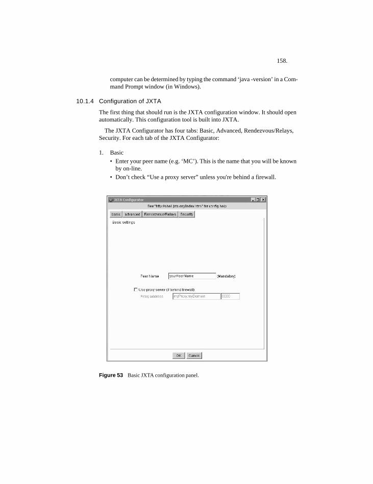
158.
computer can be determined by typing the command ‘java -version’ in a Com-mand Prompt window (in Windows).
10.1.4 Configuration of JXTA
The first thing that should run is the JXTA configuration window. It should open automatically. This configuration tool is built into JXTA.
The JXTA Configurator has four tabs: Basic, Advanced, Rendezvous/Relays, Security. For each tab of the JXTA Configurator:
1. Basic • Enter your peer name (e.g. ‘MC’). This is the name that you will be known
by on-line.• Don’t check “Use a proxy server” unless you're behind a firewall.
Figure 53 Basic JXTA configuration panel.
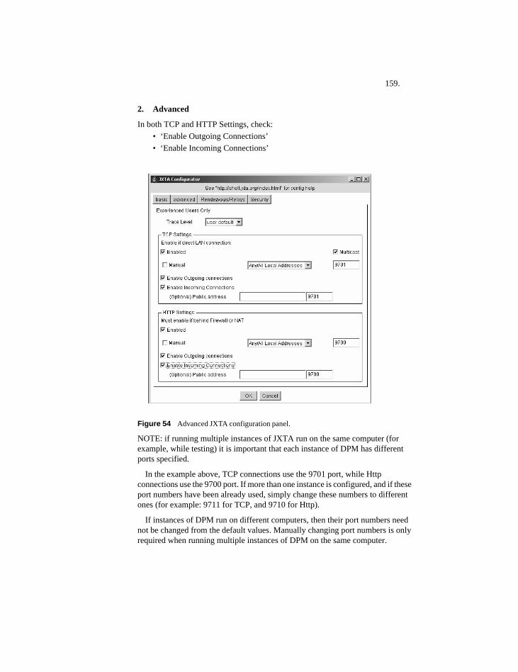
159.
2. Advanced
In both TCP and HTTP Settings, check:• ‘Enable Outgoing Connections’• ‘Enable Incoming Connections’
Figure 54 Advanced JXTA configuration panel.
NOTE: if running multiple instances of JXTA run on the same computer (for example, while testing) it is important that each instance of DPM has different ports specified.
In the example above, TCP connections use the 9701 port, while Http connections use the 9700 port. If more than one instance is configured, and if these port numbers have been already used, simply change these numbers to different ones (for example: 9711 for TCP, and 9710 for Http).
If instances of DPM run on different computers, then their port numbers need not be changed from the default values. Manually changing port numbers is only required when running multiple instances of DPM on the same computer.
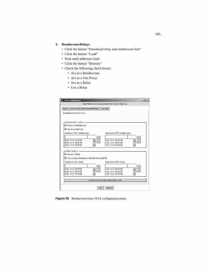
160.
3. Rendezvous/Relays• Click the button “Download relay and rendezvous lists”• Click the button “Load”• Wait until addresses load• Click the button “Dismiss”• Check the following check boxes:
• Act as a Rendezvous• Act as a Jxta Proxy• Act as a Relay• Use a Relay
Figure 55 Rendezvous/relay JXTA configuration panel.
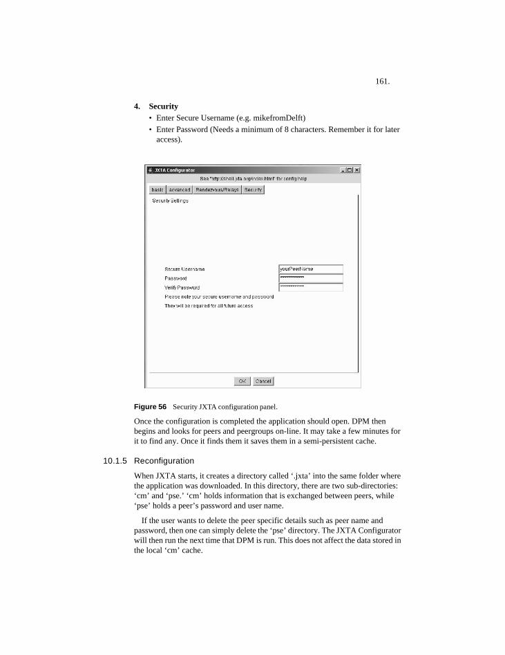
161.
4. Security• Enter Secure Username (e.g. mikefromDelft)• Enter Password (Needs a minimum of 8 characters. Remember it for later
access).
Figure 56 Security JXTA configuration panel.
Once the configuration is completed the application should open. DPM then begins and looks for peers and peergroups on-line. It may take a few minutes for it to find any. Once it finds them it saves them in a semi-persistent cache.
10.1.5 Reconfiguration
When JXTA starts, it creates a directory called ‘.jxta’ into the same folder where the application was downloaded. In this directory, there are two sub-directories: ‘cm’ and ‘pse.’ ‘cm’ holds information that is exchanged between peers, while ‘pse’ holds a peer’s password and user name.
If the user wants to delete the peer specific details such as peer name and password, then one can simply delete the ‘pse’ directory. The JXTA Configurator will then run the next time that DPM is run. This does not affect the data stored in the local ‘cm’ cache.
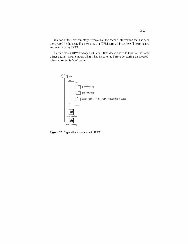
162.
Deletion of the ‘cm’ directory, removes all the cached information that has been discovered by the peer. The next time that DPM is run, this cache will be recreated automatically by JXTA.
If a user closes DPM and opens it later, DPM doesn't have to look for the same things again—it remembers what it has discovered before by storing discovered information in its ‘cm’ cache.
Figure 57 Typical local user cache in JXTA.
uuid-3FD35406FFC44A81A406B8C1C7C79E1302
.jxta
cm
pse
jxta-NetGroup
PlatformConfig
jxta.properties
jxta-NetGroup
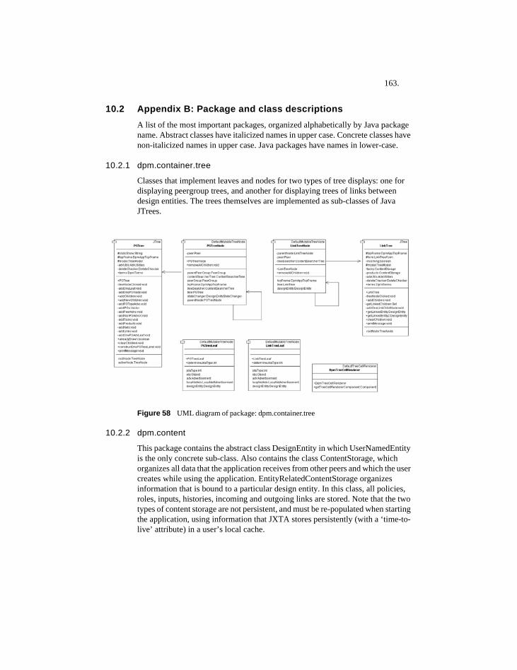
163.
10.2 Appendix B: Package and class descriptionsA list of the most important packages, organized alphabetically by Java package name. Abstract classes have italicized names in upper case. Concrete classes have non-italicized names in upper case. Java packages have names in lower-case.
10.2.1 dpm.container.tree
Classes that implement leaves and nodes for two types of tree displays: one for displaying peergroup trees, and another for displaying trees of links between design entities. The trees themselves are implemented as sub-classes of Java JTrees.
Figure 58 UML diagram of package: dpm.container.tree
10.2.2 dpm.content
This package contains the abstract class DesignEntity in which UserNamedEntity is the only concrete sub-class. Also contains the class ContentStorage, which organizes all data that the application receives from other peers and which the user creates while using the application. EntityRelatedContentStorage organizes information that is bound to a particular design entity. In this class, all policies, roles, inputs, histories, incoming and outgoing links are stored. Note that the two types of content storage are not persistent, and must be re-populated when starting the application, using information that JXTA stores persistently (with a ‘time-to-live’ attribute) in a user’s local cache.
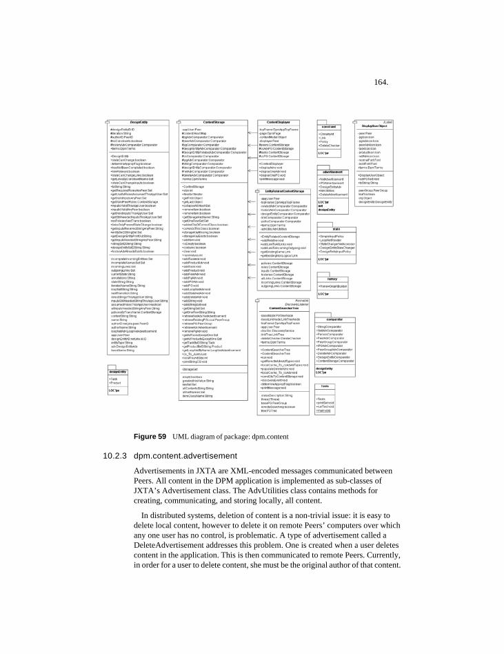
164.
Figure 59 UML diagram of package: dpm.content
10.2.3 dpm.content.advertisement
Advertisements in JXTA are XML-encoded messages communicated between Peers. All content in the DPM application is implemented as sub-classes of JXTA’s Advertisement class. The AdvUtilities class contains methods for creating, communicating, and storing locally, all content.
In distributed systems, deletion of content is a non-trivial issue: it is easy to delete local content, however to delete it on remote Peers’ computers over which any one user has no control, is problematic. A type of advertisement called a DeleteAdvertisement addresses this problem. One is created when a user deletes content in the application. This is then communicated to remote Peers. Currently, in order for a user to delete content, she must be the original author of that content.
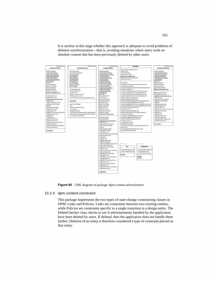
165.
It is unclear at this stage whether this approach is adequate to avoid problems of deletion synchronization—that is, avoiding situations where users work on obsolete content that has been previously deleted by other users.
Figure 60 UML diagram of package: dpm.content.advertisement
10.2.4 dpm.content.constraint
This package implements the two types of state-change constraining classes in DPM: Links and Policies. Links are constraints between two existing entities, while Policies are constraints specific to a single transition in a design entity. The DeleteChecker class checks to see if advertisements handled by the application have been deleted by users. If deleted, then the application does not handle them further. Deletion of an entity is therefore considered a type of constraint placed on that entity.
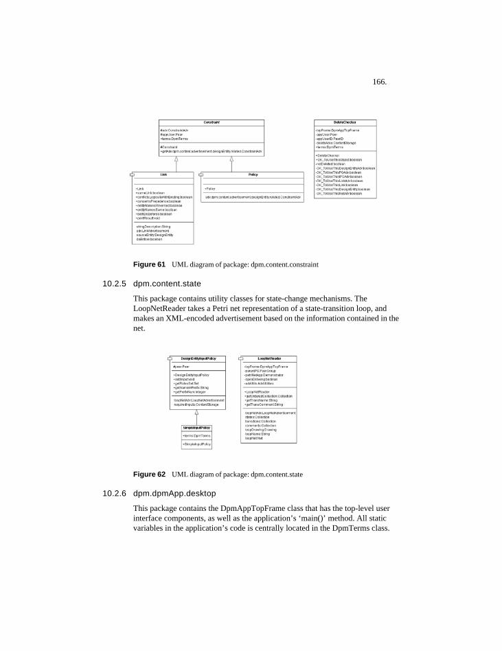
166.
Figure 61 UML diagram of package: dpm.content.constraint
10.2.5 dpm.content.state
This package contains utility classes for state-change mechanisms. The LoopNetReader takes a Petri net representation of a state-transition loop, and makes an XML-encoded advertisement based on the information contained in the net.
Figure 62 UML diagram of package: dpm.content.state
10.2.6 dpm.dpmApp.desktop
This package contains the DpmAppTopFrame class that has the top-level user interface components, as well as the application’s ‘main()’ method. All static variables in the application’s code is centrally located in the DpmTerms class.
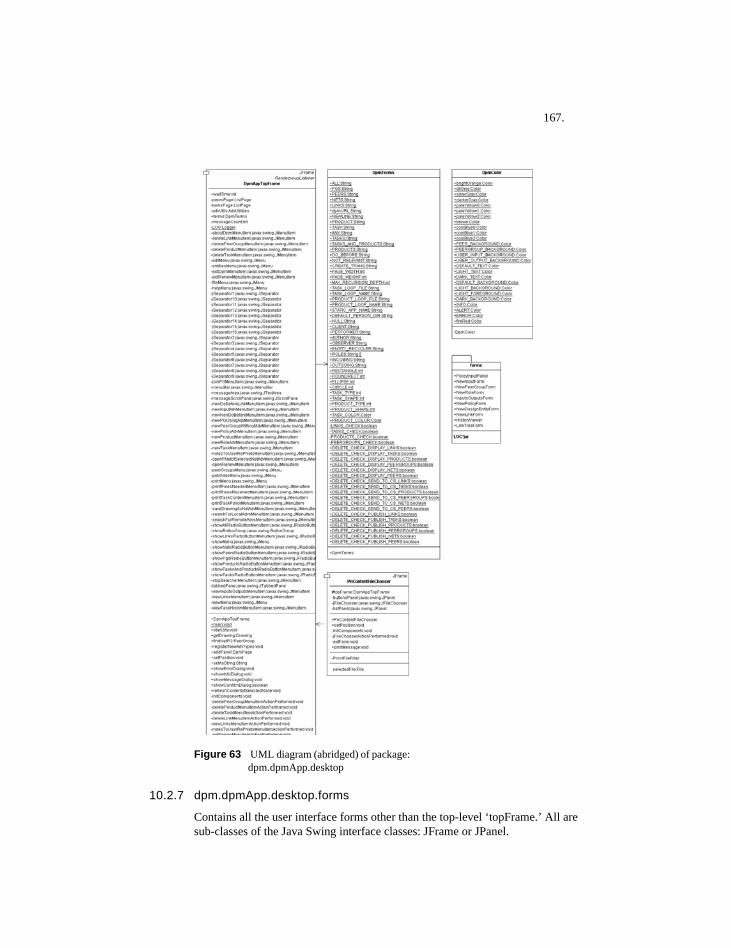
167.
Figure 63 UML diagram (abridged) of package: dpm.dpmApp.desktop
10.2.7 dpm.dpmApp.desktop.forms
Contains all the user interface forms other than the top-level ‘topFrame.’ All are sub-classes of the Java Swing interface classes: JFrame or JPanel.
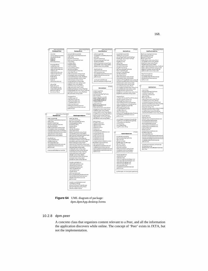
168.
Figure 64 UML diagram of package: dpm.dpmApp.desktop.forms
10.2.8 dpm.peer
A concrete class that organizes content relevant to a Peer, and all the information the application discovers while online. The concept of ‘Peer’ exists in JXTA, but not the implementation.
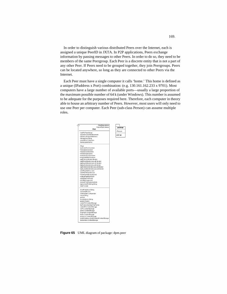
169.
In order to distinguish various distributed Peers over the Internet, each is assigned a unique PeerID in JXTA. In P2P applications, Peers exchange information by passing messages to other Peers. In order to do so, they need to be members of the same Peergroup. Each Peer is a discrete entity that is not a part of any other Peer. If Peers need to be grouped together, they join Peergroups. Peers can be located anywhere, so long as they are connected to other Peers via the Internet.
Each Peer must have a single computer it calls ‘home.’ This home is defined as a unique (IPaddress x Port) combination: (e.g. 130.161.162.233 x 9701). Most computers have a large number of available ports—usually a large proportion of the maximum possible number of 64 k (under Windows). This number is assumed to be adequate for the purposes required here. Therefore, each computer in theory able to house an arbitrary number of Peers. However, most users will only need to use one Peer per computer. Each Peer (sub-class Person) can assume multiple roles.
Figure 65 UML diagram of package: dpm.peer
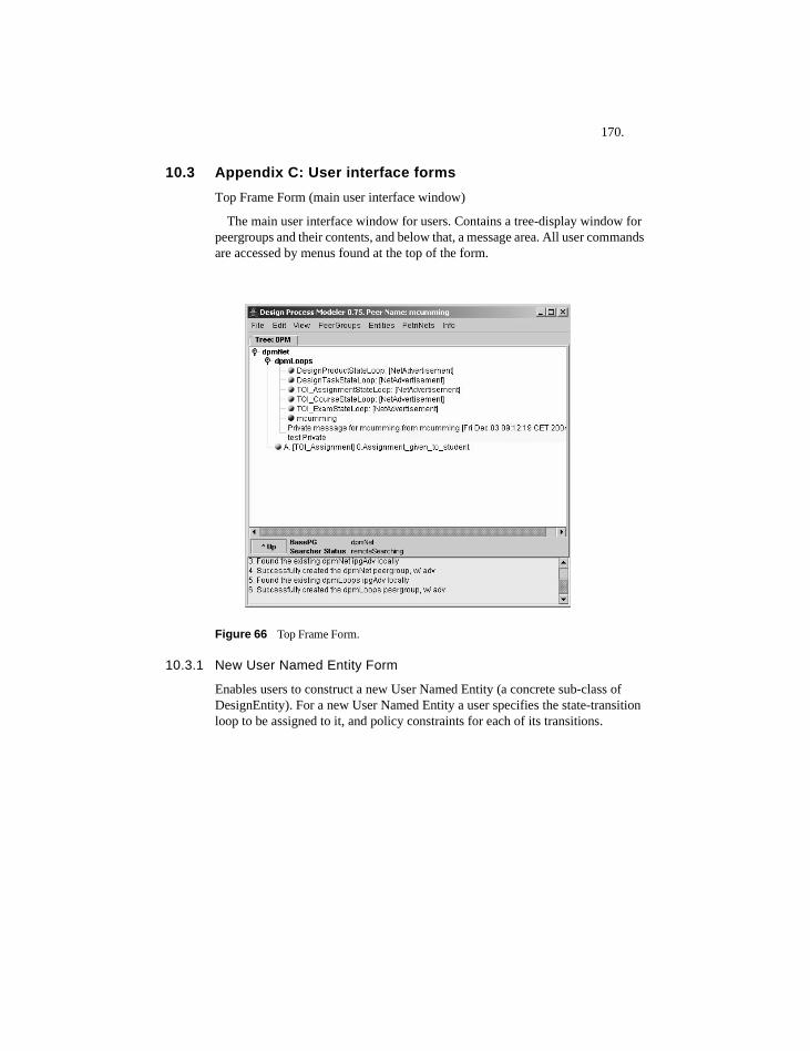
170.
10.3 Appendix C: User interface formsTop Frame Form (main user interface window)
The main user interface window for users. Contains a tree-display window for peergroups and their contents, and below that, a message area. All user commands are accessed by menus found at the top of the form.
Figure 66 Top Frame Form.
10.3.1 New User Named Entity Form
Enables users to construct a new User Named Entity (a concrete sub-class of DesignEntity). For a new User Named Entity a user specifies the state-transition loop to be assigned to it, and policy constraints for each of its transitions.
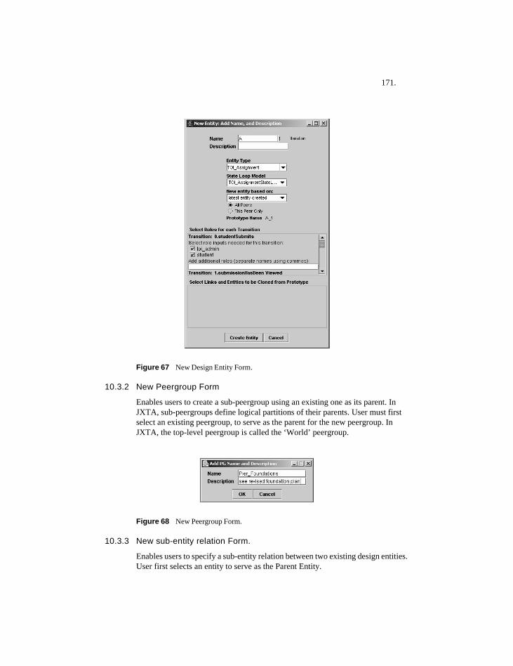
171.
Figure 67 New Design Entity Form.
10.3.2 New Peergroup Form
Enables users to create a sub-peergroup using an existing one as its parent. In JXTA, sub-peergroups define logical partitions of their parents. User must first select an existing peergroup, to serve as the parent for the new peergroup. In JXTA, the top-level peergroup is called the ‘World’ peergroup.
Figure 68 New Peergroup Form.
10.3.3 New sub-entity relation Form.
Enables users to specify a sub-entity relation between two existing design entities. User first selects an entity to serve as the Parent Entity.
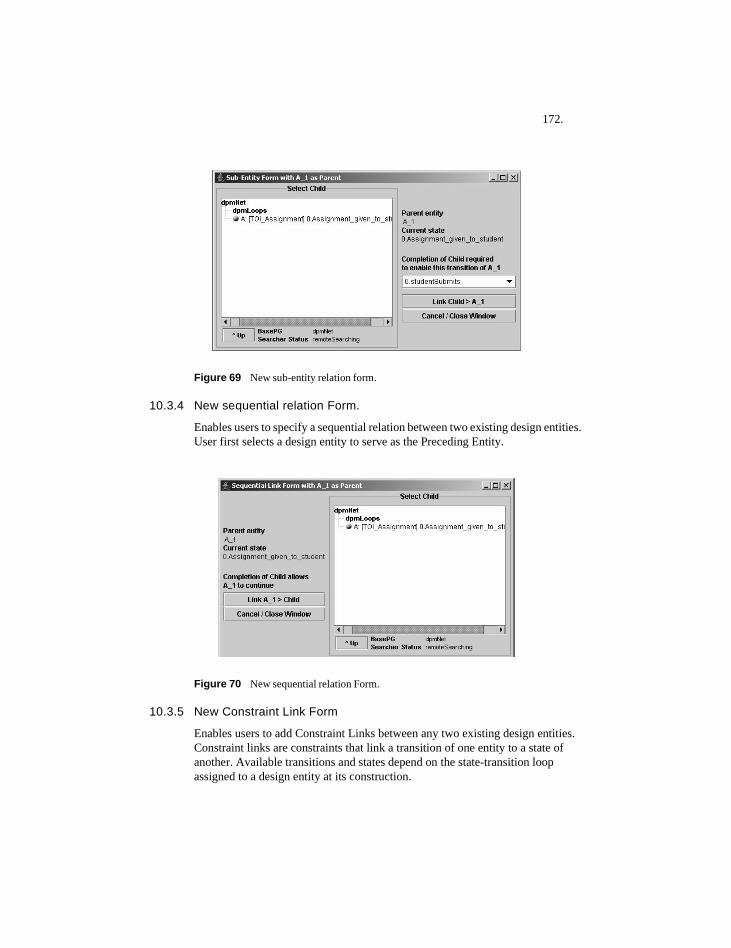
172.
Figure 69 New sub-entity relation form.
10.3.4 New sequential relation Form.
Enables users to specify a sequential relation between two existing design entities. User first selects a design entity to serve as the Preceding Entity.
Figure 70 New sequential relation Form.
10.3.5 New Constraint Link Form
Enables users to add Constraint Links between any two existing design entities. Constraint links are constraints that link a transition of one entity to a state of another. Available transitions and states depend on the state-transition loop assigned to a design entity at its construction.
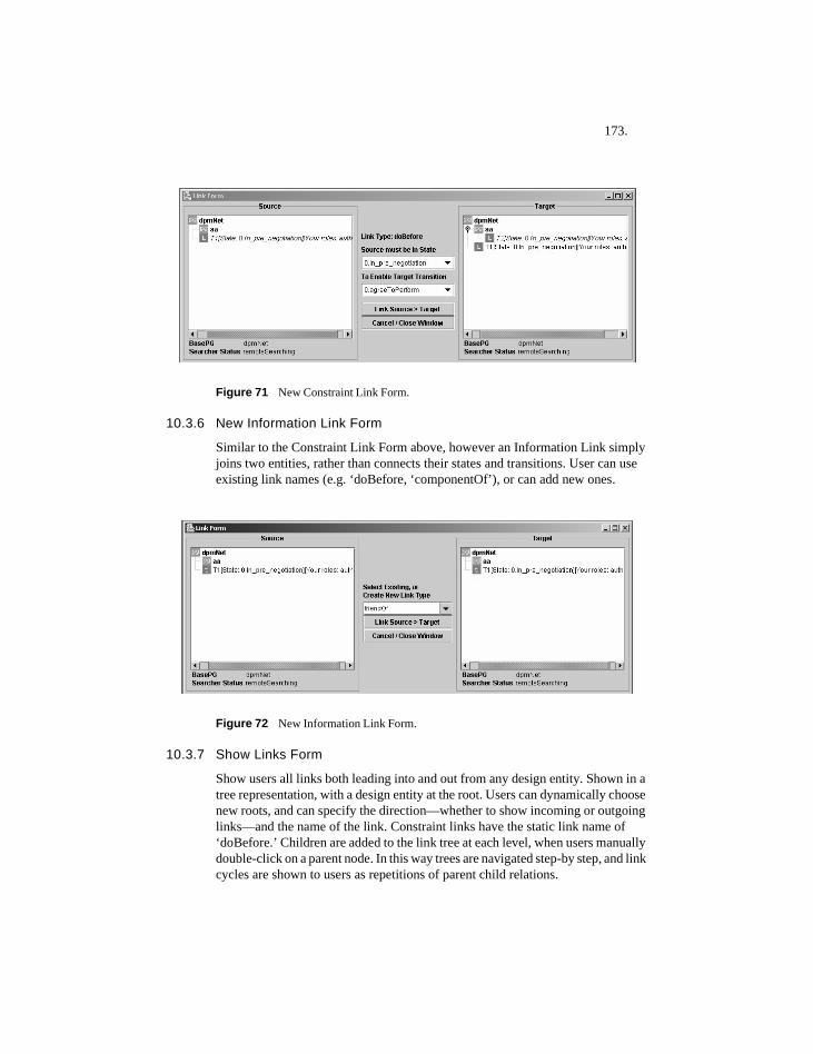
173.
Figure 71 New Constraint Link Form.
10.3.6 New Information Link Form
Similar to the Constraint Link Form above, however an Information Link simply joins two entities, rather than connects their states and transitions. User can use existing link names (e.g. ‘doBefore, ‘componentOf’), or can add new ones.
Figure 72 New Information Link Form.
10.3.7 Show Links Form
Show users all links both leading into and out from any design entity. Shown in a tree representation, with a design entity at the root. Users can dynamically choose new roots, and can specify the direction—whether to show incoming or outgoing links—and the name of the link. Constraint links have the static link name of ‘doBefore.’ Children are added to the link tree at each level, when users manually double-click on a parent node. In this way trees are navigated step-by step, and link cycles are shown to users as repetitions of parent child relations.
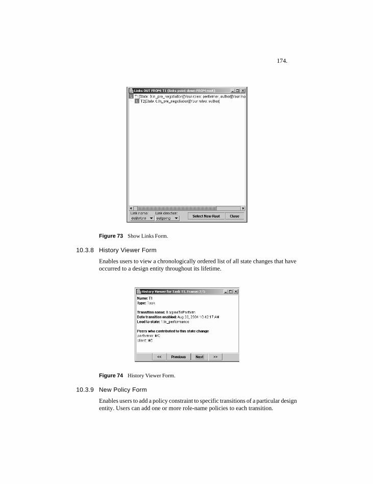
174.
Figure 73 Show Links Form.
10.3.8 History Viewer Form
Enables users to view a chronologically ordered list of all state changes that have occurred to a design entity throughout its lifetime.
Figure 74 History Viewer Form.
10.3.9 New Policy Form
Enables users to add a policy constraint to specific transitions of a particular design entity. Users can add one or more role-name policies to each transition.
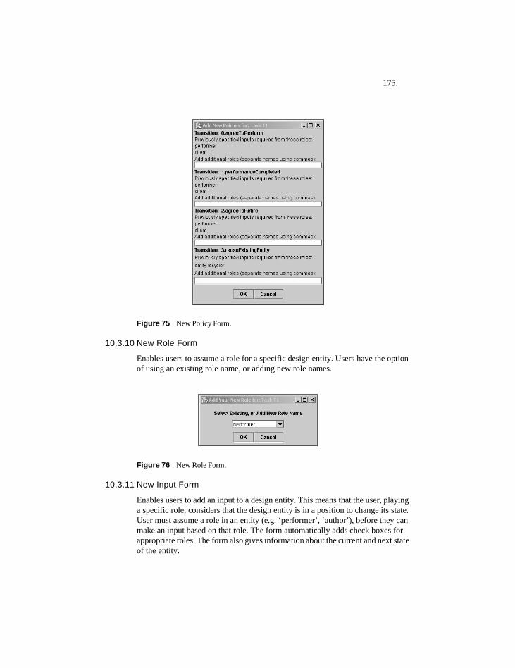
175.
Figure 75 New Policy Form.
10.3.10 New Role Form
Enables users to assume a role for a specific design entity. Users have the option of using an existing role name, or adding new role names.
Figure 76 New Role Form.
10.3.11 New Input Form
Enables users to add an input to a design entity. This means that the user, playing a specific role, considers that the design entity is in a position to change its state. User must assume a role in an entity (e.g. ‘performer’, ‘author’), before they can make an input based on that role. The form automatically adds check boxes for appropriate roles. The form also gives information about the current and next state of the entity.
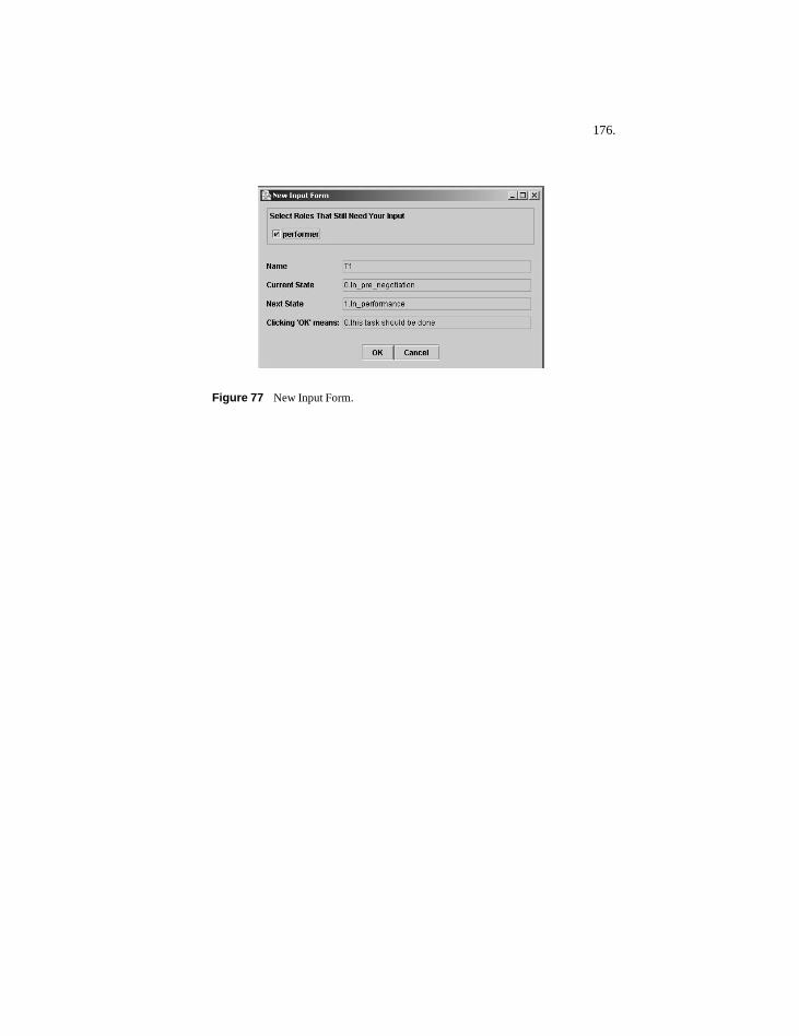
176.
Figure 77 New Input Form.
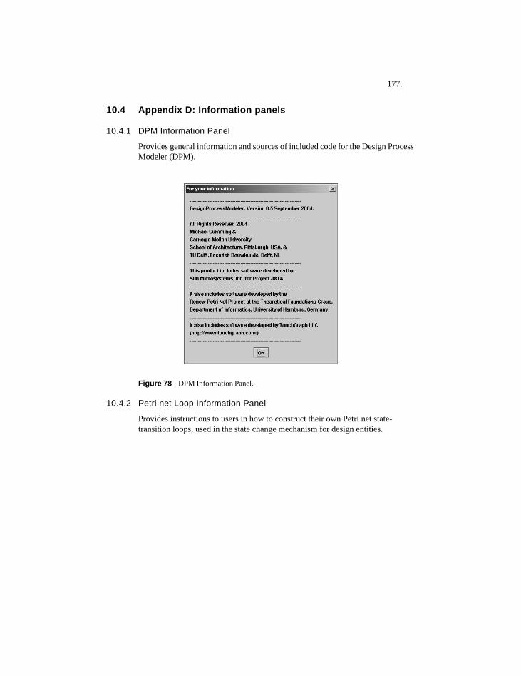
177.
10.4 Appendix D: Information panels
10.4.1 DPM Information Panel
Provides general information and sources of included code for the Design Process Modeler (DPM).
Figure 78 DPM Information Panel.
10.4.2 Petri net Loop Information Panel
Provides instructions to users in how to construct their own Petri net state-transition loops, used in the state change mechanism for design entities.
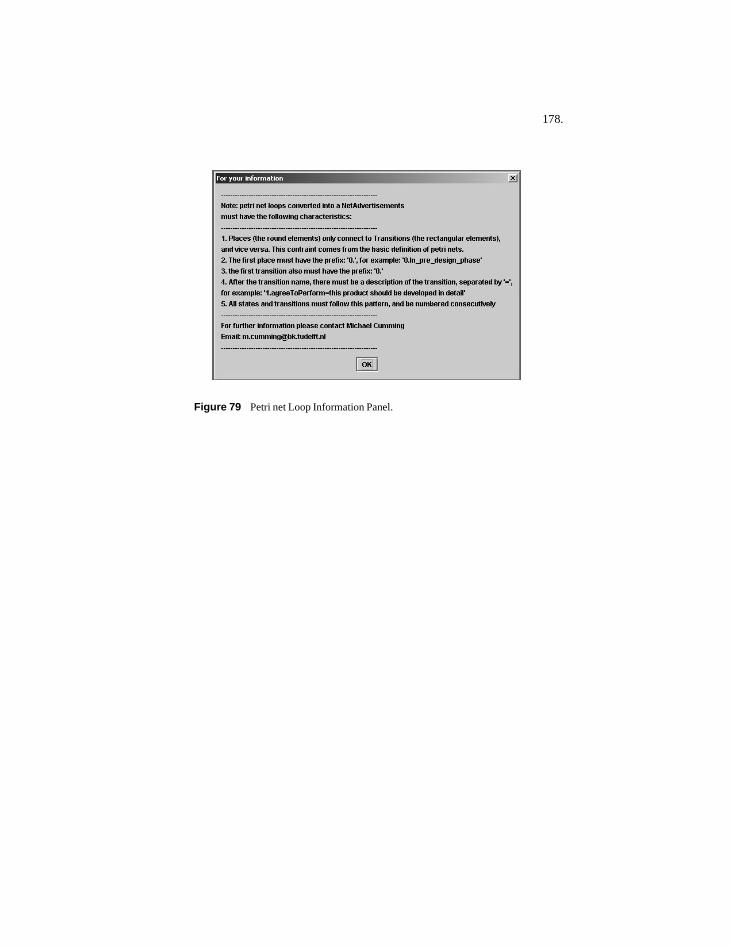
178.
Figure 79 Petri net Loop Information Panel.
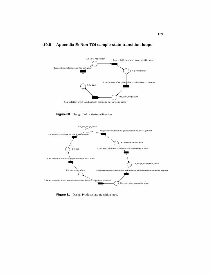
179.
10.5 Appendix E: Non-TOI sample state-transition loops
Figure 80 Design Task state-transition loop.
Figure 81 Design Product state-transition loop.
0.In_pre_negotiation
1.In_performance
2.In_post_negotiation
3.Retired
0.agreeToPerform=this task should be done
1.performanceCompleted=this task has been completed
2.agreeToRetire=this task has been completed to your satisfaction
3.reuseExistingEntity=use this task again
0.In_pre_design_phase
1.In_schematic_design_phase
2.In_design_development_phase
3.In_construction_documents_phase
4.In_post_design_phase
5.Retired
0.requirementsGathered=design requirements have been gathered
1.agreeToDesignInDetail=this product should be developed in detail
2.designDevelopmentCompleted=this product should have construction documents prepared
3.documentsCompleted=this product's construction documents have been completed
4.postDesignComplete=the design contract has been fulf illed
5.reuseExistingEntity=use this task or product again
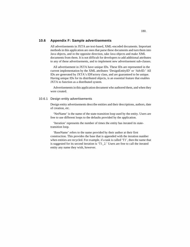
180.
10.6 Appendix F: Sample advertisementsAll advertisements in JXTA are text-based, XML-encoded documents. Important methods in this application are ones that parse these documents and turn them into Java objects, and in the opposite direction, take Java objects and make XML documents from them. It is not difficult for developers to add additional attributes to any of these advertisements, and to implement new advertisement sub-classes.
All advertisement in JXTA have unique IDs. These IDs are represented in the current implementation by the XML attributes ‘DesignEntityID’ or ‘AdvID.’ All IDs are generated by JXTA’s IDFactory class, and are guaranteed to be unique. Having unique IDs for its distributed objects, is an essential feature that enables JXTA to function as a distributed system.
Advertisements in this application document who authored them, and when they were created.
10.6.1 Design entity advertisements
Design entity advertisements describe entities and their descriptions, authors, date of creation, etc.
‘NetName’ is the name of the state-transition loop used by the entity. Users are free to use different loops to the defaults provided by the application.
‘Iteration’ represents the number of times the entity has iterated its state-transition loop.
‘BaseName’ refers to the name provided by their author at their first construction. This provides the base that is appended with the iteration number when entities are recycled. For example, if a task is called ‘T1’, then the name that is suggested for its second iteration is ‘T1_2.’ Users are free to call the iterated entity any name they wish, however.
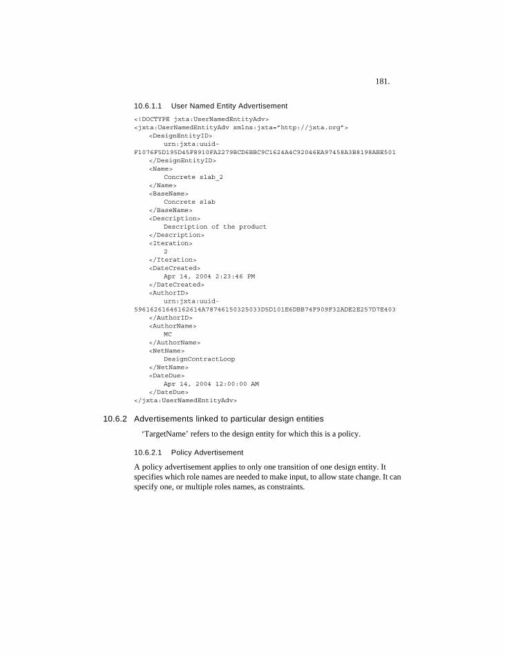
181.
10.6.1.1 User Named Entity Advertisement
<!DOCTYPE jxta:UserNamedEntityAdv><jxta:UserNamedEntityAdv xmlns:jxta=”http://jxta.org”>
<DesignEntityID>urn:jxta:uuid-
F1076F5D195D45F8910FA2279BCD6BBC9C1624A4C92046EA97458A3B8198ABE501</DesignEntityID><Name>
Concrete slab_2</Name><BaseName>
Concrete slab</BaseName><Description>
Description of the product</Description><Iteration>
2</Iteration><DateCreated>
Apr 14, 2004 2:23:46 PM</DateCreated><AuthorID>
urn:jxta:uuid-59616261646162614A78746150325033D5D101E6DBB74F909F32ADE2E257D7E403
</AuthorID><AuthorName>
MC</AuthorName><NetName>
DesignContractLoop</NetName><DateDue>
Apr 14, 2004 12:00:00 AM</DateDue>
</jxta:UserNamedEntityAdv>
10.6.2 Advertisements linked to particular design entities
‘TargetName’ refers to the design entity for which this is a policy.
10.6.2.1 Policy Advertisement
A policy advertisement applies to only one transition of one design entity. It specifies which role names are needed to make input, to allow state change. It can specify one, or multiple roles names, as constraints.
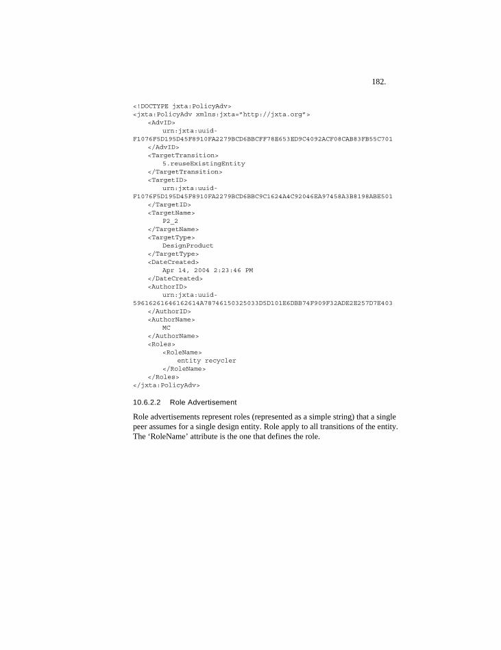
182.
<!DOCTYPE jxta:PolicyAdv><jxta:PolicyAdv xmlns:jxta=”http://jxta.org”>
<AdvID>urn:jxta:uuid-
F1076F5D195D45F8910FA2279BCD6BBCFF78E653ED9C4092ACF08CAB83FB55C701</AdvID><TargetTransition>
5.reuseExistingEntity</TargetTransition><TargetID>
urn:jxta:uuid-F1076F5D195D45F8910FA2279BCD6BBC9C1624A4C92046EA97458A3B8198ABE501
</TargetID><TargetName>
P2_2</TargetName><TargetType>
DesignProduct</TargetType><DateCreated>
Apr 14, 2004 2:23:46 PM</DateCreated><AuthorID>
urn:jxta:uuid-59616261646162614A78746150325033D5D101E6DBB74F909F32ADE2E257D7E403
</AuthorID><AuthorName>
MC</AuthorName><Roles>
<RoleName>entity recycler
</RoleName></Roles>
</jxta:PolicyAdv>
10.6.2.2 Role Advertisement
Role advertisements represent roles (represented as a simple string) that a single peer assumes for a single design entity. Role apply to all transitions of the entity. The ‘RoleName’ attribute is the one that defines the role.
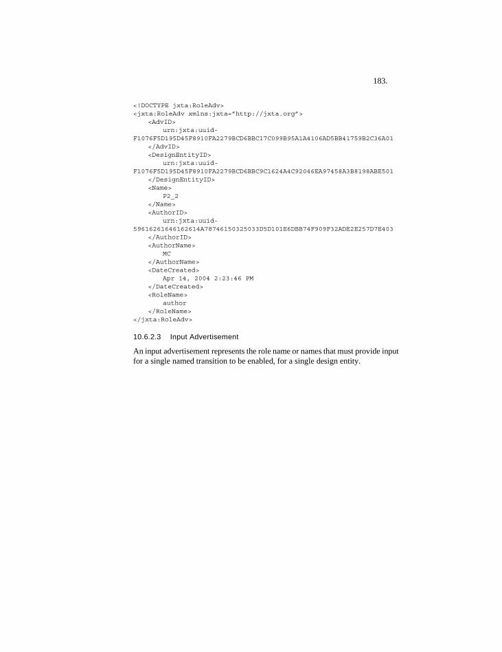
183.
<!DOCTYPE jxta:RoleAdv><jxta:RoleAdv xmlns:jxta=”http://jxta.org”>
<AdvID>urn:jxta:uuid-
F1076F5D195D45F8910FA2279BCD6BBC17C099B95A1A4106AD5BB41759B2C36A01</AdvID><DesignEntityID>
urn:jxta:uuid-F1076F5D195D45F8910FA2279BCD6BBC9C1624A4C92046EA97458A3B8198ABE501
</DesignEntityID><Name>
P2_2</Name><AuthorID>
urn:jxta:uuid-59616261646162614A78746150325033D5D101E6DBB74F909F32ADE2E257D7E403
</AuthorID><AuthorName>
MC</AuthorName><DateCreated>
Apr 14, 2004 2:23:46 PM</DateCreated><RoleName>
author</RoleName>
</jxta:RoleAdv>
10.6.2.3 Input Advertisement
An input advertisement represents the role name or names that must provide input for a single named transition to be enabled, for a single design entity.
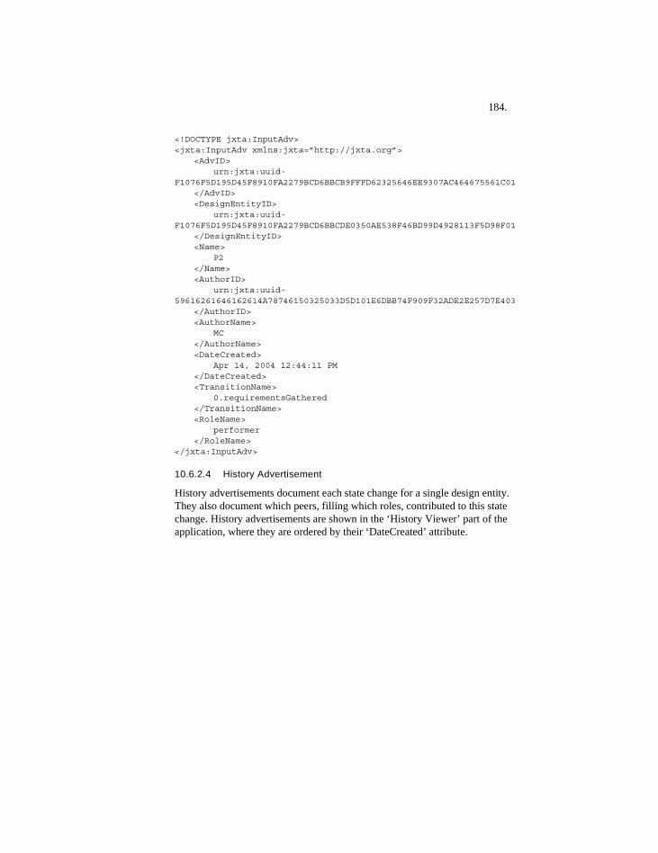
184.
<!DOCTYPE jxta:InputAdv><jxta:InputAdv xmlns:jxta=”http://jxta.org”>
<AdvID>urn:jxta:uuid-
F1076F5D195D45F8910FA2279BCD6BBCB9FFFD62325646EE9307AC464675561C01</AdvID><DesignEntityID>
urn:jxta:uuid-F1076F5D195D45F8910FA2279BCD6BBCDE0350AE538F46BD99D4928113F5D98F01
</DesignEntityID><Name>
P2</Name><AuthorID>
urn:jxta:uuid-59616261646162614A78746150325033D5D101E6DBB74F909F32ADE2E257D7E403
</AuthorID><AuthorName>
MC</AuthorName><DateCreated>
Apr 14, 2004 12:44:11 PM</DateCreated><TransitionName>
0.requirementsGathered</TransitionName><RoleName>
performer</RoleName>
</jxta:InputAdv>
10.6.2.4 History Advertisement
History advertisements document each state change for a single design entity. They also document which peers, filling which roles, contributed to this state change. History advertisements are shown in the ‘History Viewer’ part of the application, where they are ordered by their ‘DateCreated’ attribute.
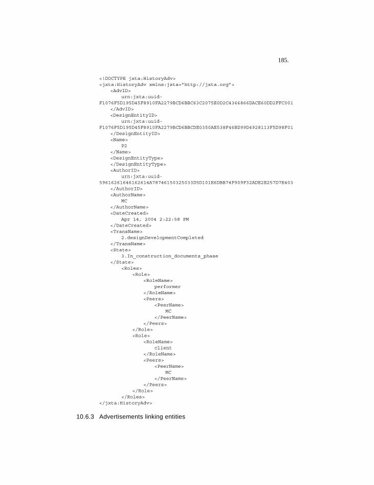
185.
<!DOCTYPE jxta:HistoryAdv><jxta:HistoryAdv xmlns:jxta=”http://jxta.org”>
<AdvID>urn:jxta:uuid-
F1076F5D195D45F8910FA2279BCD6BBC63C2075E0D2C4366866DACE60DD2FFC001</AdvID><DesignEntityID>
urn:jxta:uuid-F1076F5D195D45F8910FA2279BCD6BBCDE0350AE538F46BD99D4928113F5D98F01
</DesignEntityID><Name>
P2</Name><DesignEntityType></DesignEntityType><AuthorID>
urn:jxta:uuid-59616261646162614A78746150325033D5D101E6DBB74F909F32ADE2E257D7E403
</AuthorID><AuthorName>
MC</AuthorName><DateCreated>
Apr 14, 2004 2:22:58 PM</DateCreated><TransName>
2.designDevelopmentCompleted</TransName><State>
3.In_construction_documents_phase</State>
<Roles><Role>
<RoleName>performer
</RoleName><Peers>
<PeerName>MC
</PeerName></Peers>
</Role><Role>
<RoleName>client
</RoleName><Peers>
<PeerName>MC
</PeerName></Peers>
</Role></Roles>
</jxta:HistoryAdv>
10.6.3 Advertisements linking entities
186.
Link advertisements are of two types: those that provide constraint for state changes (Constraint Links), and those that are merely informative (Information Links).
The state of the source entity, and the target transition must be specified for constraint links. For information links, such information is not required or relevant.
Constraint link advertisements currently have the static ‘ConstraintName’ of ‘doBefore.’ For information links, any ‘ConstraintName’ value is acceptable.
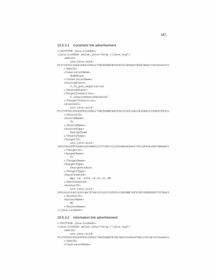
187.
10.6.3.1 Constraint link advertisement
<!DOCTYPE jxta:LinkAdv><jxta:LinkAdv xmlns:jxta=”http://jxta.org”>
<AdvID>urn:jxta:uuid-
F1076F5D195D45F8910FA2279BCD6BBCE0868CC32E5E497B987BAA37583D46D301</AdvID><ConstraintName>
doBefore</ConstraintName><SourceState>
0.In_pre_negotiation</SourceState><TargetTransition>
0.requirementsGathered</TargetTransition><SourceID>
urn:jxta:uuid-F1076F5D195D45F8910FA2279BCD6BBC4899961F18514A12836AA3535D892F8301
</SourceID><SourceName>
T1</SourceName><SourceType>
DesignTask</SourceType><TargetID>
urn:jxta:uuid-3FD35406FFC44A81A406B8C1C7C79E13532964A896684079912F95A38876B84A01
</TargetID><TargetName>
P1</TargetName><TargetType>
DesignProduct</TargetType><DateCreated>
Apr 14, 2004 12:21:01 PM</DateCreated><AuthorID>
urn:jxta:uuid-59616261646162614A78746150325033D5D101E6DBB74F909F32ADE2E257D7E403
</AuthorID><AuthorName>
MC</AuthorName>
</jxta:LinkAdv>
10.6.3.2 Information link advertisement
<!DOCTYPE jxta:LinkAdv><jxta:LinkAdv xmlns:jxta=”http://jxta.org”>
<AdvID>urn:jxta:uuid-
F1076F5D195D45F8910FA2279BCD6BBCE7E47AD0358840F9B23C810A781454A001</AdvID><ConstraintName>
188.
friendOf</ConstraintName><SourceState>
not relevant</SourceState><TargetTransition>
not relevant</TargetTransition><SourceID>
urn:jxta:uuid-F1076F5D195D45F8910FA2279BCD6BBC4899961F18514A12836AA3535D892F8301
</SourceID><SourceName>
T1</SourceName><SourceType>
DesignTask</SourceType><TargetID>
urn:jxta:uuid-3FD35406FFC44A81A406B8C1C7C79E13532964A896684079912F95A38876B84A01
</TargetID><TargetName>
P1</TargetName><TargetType>
DesignProduct</TargetType><DateCreated>
Apr 14, 2004 12:11:59 PM</DateCreated><AuthorID>
urn:jxta:uuid-59616261646162614A78746150325033D5D101E6DBB74F909F32ADE2E257D7E403
</AuthorID><AuthorName>
MC</AuthorName>
</jxta:LinkAdv>

189.

190.