Embed Size (px)
Citation preview
JOURNAL OF INFORMATION SCIENCE AND ENGINEERING 18, 59-84 (2002)
59
Constructing an Object-Oriented Architecture for Web Application Testing
JI-TZAY YANG, JIUN-LONG HUANG, FENG-JIAN WANG
AND WILLIAM. C. CHU*
Department of Computer Science and Information Engineering National Chiao Tung University
Hsinchu, 300 Taiwan E-mail: {jjyang,jlhuang,fjwang}@csie.nctu.edu.tw
* Department of Computer Information Science TungHai University
Taichung, 400 Taiwan E-mail: [email protected]
The variety of existing web application frameworks has lead to the development of
a wide range of Web applications for both the Internet and intranets. Web applications are constructed based on various frameworks ranging from simple HTML-based forms to complicated distributed-object computations based on Java and CORBA. Web soft-ware enables programmers to choose a proper framework for their own Web applications. The prevalence of Web-based applications has also led to the need to adapt software testing frameworks and tools for them. This study presents a software testing architecture that integrates several common but enhanced testing tools as a sub-architecture to fit a common Web application framework. The architecture reuses several software patterns and architectures from traditional testing environments. A Web application testing envi-ronment prototype is also constructed to demonstrate the feasibility of the proposed ar-chitecture.
Keywords: web application testing, software architecture, framework reuse, object- ori-
entation, software testing
1. INTRODUCTION
The frameworks of Web-based applications provide application designers with flexibility in choosing proper development tools for their implementations of Web-based applications. The author in [1] radically investigated and identified several categories of solutions for Web application development. However, developers of large Web applica-tions currently do not have enough powerful tools to debug or test their Web applications. The author in [2] addressed the necessity of software testing support to handle the com-plexity of Web applications. Existing Web testing tools generally verify the syntax in HTML documents, confirm the hyper-link integrity of a set of HTML documents, test the
Received December 3, 1999; revised April 17 & July 25, 2000; accepted July 31, 2000. Communicated by Michael R. Lyu.

JI-TZAY YANG, JIUN-LONG HUANG, FENG-JIAN WANG AND WILLIAM CHENG-CHUNG CHU
60
GUI components embedded in the browsers, and measure the performance of the Web application. Few products support overall Web application testing [3]. The researchers in [4] and [5] tested software components, such as Java Applet and ActiveX controls, that are frequently embedded in Web pages. The author in [6] extended traditional GUI test-ing tools to analyze GUI events inside Web browsers. The author in [7] justified the con-tents of a Web browser's window by matching text patterns or performing a pixel-level comparison. The researcher in [8] checked popular Web browser documents for syntax and compatibility. Each of the tools mentioned above tests only one or some aspects of Web applications. To thoroughly test Web-based application, an adapted software testing architecture that integrates both traditional testing techniques and modern web-related software testing support is needed.
This work presents a software architecture that integrates several testing tools by extending traditional software testing architectures and software patterns [9, 10] to coor-dinate the design and specification of Web-application testing tasks. Integrating Web-testing components can reduce the insufficiency of available independent Web test-ing tools mentioned above for complicated Web application testing. This object-oriented architecture provides a clear picture of the software components to be reused, including tool reuse and architecture reuse. A testing environment for Web applications is con-structed to demonstrate the reusability of the proposed architecture.
The rest of the paper is organized as follows. Section 2 discusses the Web applica-tion testing issues based on popular Web application development models and traditional testing techniques. Section 3 presents the software architecture that accommodates the Web software testing tools. Section 4 presents a prototype of the testing environment constructed under the architecture while a conclusion is provided in Section 5.
2. CUSTOMIZE TESTING ARCHITECTURES TO TEST WEB APPLICATIONS
2.1 Web Application Constituents
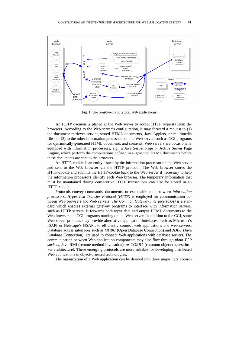
The structure of a Web application allows application platforms or application de-signers to place code for Web computation at several locations. Fig. 1 depicts the typical constituents of the Web application. The contents of a Web application (static HTML documents, image files, video files, or even programs that run on Web servers or Web clients) are normally stored on the Web server or database server. The information processor in the Web application model accepts incoming requests and responds to them with the appropriate contents. A request is either processed and returned directly or translated and delegated to another information processor prior to the response.
The Web browser is capable of retrieving requested hyper-text documents from the Web server via the HTTP protocol. The hyper-text document is rendered in HTML (Hy-per-Text Markup Language) format on the screen. Contemporary Web browsers also embed a Java virtual machine and a Java Script interpreter to execute the Java Applets or Java Scripts specified in the documents. Additional information processors, such as Net-scape Communicator’s plug-in modules and Microsoft Explorer’s ActiveX controls, are browser-loadable software modules that can extend a browser’s functionality.
CONSTRUCTING AN OBJECT-ORIENTED ARCHITECTURE FOR WEB APPLICATION TESTING
61
AugmentedHTML
Document
DatabaseServer
Socket/RMI/
CORBA
Image, Sound, Animation
Plain HTML Document
Java Applet
ServerSide
Intepreter
WebBrowser
WebServer
DatabaseServer
JavaVM
JavaScript
Intepreter
Plug-InProcessor
HTMLRender
CGIPrograms
NetworkApplication
Server
Front
End
Tier
Protocol /Interface
InformationFlow
InformationProcessor
WebDocument
LegendCommonGatewayInterface
(CGI)
HTTP
Database AccessProtocol
Database AccessProtocol
Database AccessProtocol
Fig. 1. The constituents of typical Web applications.
An HTTP daemon is placed at the Web server to accept HTTP requests from the
browsers. According to the Web server’s configuration, it may forward a request to (1) the document retriever serving stored HTML documents, Java Applets, or multimedia files, or (2) to the other information processors on the Web server, such as CGI programs for dynamically generated HTML documents and contents. Web servers are occasionally equipped with information processors, e.g., a Java Server Page or Active Server Page Engine, which perform the computations defined in augmented HTML documents before these documents are sent to the browsers.
An HTTP-cookie is an entity issued by the information processor on the Web server and sent to the Web browser via the HTTP protocol. The Web browser stores the HTTP-cookie and submits the HTTP-cookie back to the Web server if necessary to help the information processors identify each Web browser. The temporary information that must be maintained during consecutive HTTP transactions can also be stored in an HTTP-cookie.
Protocols convey commands, documents, or executable code between information processors. Hyper-Text Transfer Protocol (HTTP) is employed for communication be-tween Web browsers and Web servers. The Common Gateway Interface (CGI) is a stan-dard which enables external gateway programs to interface with information servers, such as HTTP servers. It forwards both input data and output HTML documents to the Web browser and CGI programs running on the Web server. In addition to the CGI, some Web server products may provide alternative application interfaces, such as Microsoft’s ISAPI or Netscape’s NSAPI, to efficiently connect web applications and web servers. Database access interfaces such as ODBC (Open Database Connection) and JDBC (Java Database Connection), are used to connect Web applications with database servers. The communication between Web application components may also flow through plain TCP sockets, Java RMI (remote method invocation), or CORBA (common object request bro-ker architecture). These emerging protocols are more suitable for developing distributed Web applications in object-oriented technologies.
The organization of a Web application can be divided into three major tiers accord-
JI-TZAY YANG, JIUN-LONG HUANG, FENG-JIAN WANG AND WILLIAM CHENG-CHUNG CHU
62
ing to the placement of the components: a Web browser tier, a Web server tier, and a da-tabase server tier. The information processed in the application is processed tier by tier. For example, user interaction is performed in the Web-browser tier, program logic com-putation is executed in the Web server tier, and the database operations are completed in the database-server tier. This Web application model is known as a kind of three-tier ap-plication architecture. Information communication between tiers is categorized as top-down and bottom-up types, in which information can be only passed from the ith tier to the i + j tier for j = 1 or j = −1. 2.2 Domain Components for Web Application Testing
Several approaches have been adopted by Web application developers to construct
Web applications according to user interaction and program logic. The following are typical and combinable scenarios in Web application construction: (1) Applications that consist of augmented HTML documents that are handled by the
processors at the server-side. The processors range from macro processors to em-bedded script (e.g. Microsoft Active Server Page, Server-side JavaScript, Java Server Page) processors.
(2) Applications that are designed as client-side scripts and are run at the client-side. Scripts written in JavaScript or VB Script are executed at the browser to perform user interaction and data validation.
(3) Applications that are originally developed in traditional languages, such as C++ or Perl, and interact with the Web client through the CGI equip themselves with Web features by adding modules to receive requests and reply to the results through the CGI (or its alternatives – Microsoft’s ISAPI and Netscape’s NSAPI).
(4) Applications that send HTTP-cookies back and forth between the Web server and the browser to track the session status and other variables.
(5) Applications that connect to database servers and primarily employ SQL statements and ODBC to communicate with the database servers. The architectures for software testing environments have been divided into the fol-
lowing five subsystems [11, 12]: (1) test development, (2) test measurement, (3) test exe-cution, (4) test failure analysis, and (5) test management. The author in [13] classified the software architecture reuse approaches as either abstraction or integration. The abstrac-tion software architecture comes from the application domain and is realized by defining objects and their operations in a domain language while the integration software architecture integrates diverse domain components into a single application.
A testing environment for Web applications can serve to specialize traditional soft-ware testing environments. An architecture that supports testing of Web applications can be obtained from a traditional one by specializing the architecture and introducing some unique domain components that support the testing tasks for Web applications. Tradi-tional software testing architectures can divide a testing system into subsystems accord-ing to the domain primitives. Both abstraction and integration aspects can be considered when revamping a traditional Web testing architecture. The abstraction aspects may be overhauled by constructing Web-related domain components (primitives) that facilitate
CONSTRUCTING AN OBJECT-ORIENTED ARCHITECTURE FOR WEB APPLICATION TESTING
63
specification of Web-related testing operations. The integration aspects may be amended by formatting the architecture in an object-oriented approach that can integrate the do-main components and perform specific tasks in a testing environment.
Domain components might be included as primitives in the testing environment to facilitate specification of web application testing tasks for the above scenarios. The pos-sible domain components (tools) are listed in terms of the Web application testing archi-tecture subsystems in Section 3. 2.3 Testing With Domain Components
Tools that perform Web application testing can be created by selecting proper do-
main components from Web-enhanced software testing architectures based on the do-main components. Testers can easily discover several new testing tools in a Web applica-tion’s testing process to increase the testing efficiency and reduce the testing effort. For example, a tool that tests Web applications written in Microsoft ASP scripts may employ a Server-Side Script Analyzer to fetch the source code of the scripts from the Web servers. It can then extract the executable code fragments in order to analyze the control and data flow within the scripts. The control-flow or data-flow information can be passed to tradi-tional flow-based test cases generators for test cases generation.
Test cases for Web application may contain the user interface operations of Web browser users. Therefore, the Test Case Executor for Web application must be designed so as to have the capability to recognize a new file format which can represent a mouse click on a Web link, an embedded image or the values filled into an HTML form. To automate the testing process, the testers can utilize testing execution components, such as Form Filler and GUI Event Generator, so that each operation predefined in the test script can be executed without the need for the testers to perform the operation manually.
Whether an application fails or passes a test case can be manually judged by the testing staff or automatically judged by the Test Oracle according to pre-defined rule(s). A Test Coverage Analyzer and its related reporting components can produce a testing report based on the percentage of the tested part and the outcome of each test case.
3. WEB TESTING ENVIRONMENT ARCHITECTURE
The authors in [11, 12] reviewed several software testing environments for tradi-tional software applications. The author in [14] also summarized several research and practitioner reports on testing object-oriented software. Based on the testing environ-ments commonly used, the authors in [11, 12] generalized software testing architectures in order to represent traditional software testing environments. This work adopts the gen-eralized architecture as a basis for developing a suitable architecture for constructing Web application testing environments. In this section, the testing architecture and its augmentation are described.
3.1 The Architecture
A software testing environment consists of five subsystems based on the reference
JI-TZAY YANG, JIUN-LONG HUANG, FENG-JIAN WANG AND WILLIAM CHENG-CHUNG CHU
64
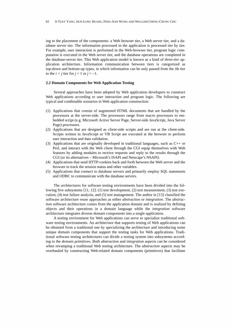
architecture given in [11]. More Web programming styles (e.g., Active Server Page and JavaScript) continue to be proposed as the number of Web applications increase. These programming styles have introduced several new-fashioned techniques that were not used in traditional software. For example, one document may contain several code frag-ments written in various programming languages, and these fragments may be inter-preted in either the browser, server, or database tiers. Therefore, one Web application should be analyzed in the browser, server, or even database tier to produce the corre-sponding analysis services for various programming languages. A novel subsystem called the Source Document Analysis Subsystem (SDAS), is added to the above architecture to solve the testing problems introduced by these unique programming styles. Fig. 2 depicts an overview of this architecture.
Source
Documents
Source Document
Analysis
Subsystem
Test Management Subsystem
Test Development
Subsystem
Test Measurement
Subsystem
Test Failure
Analysis
Subsystem
Test Execution
Subsystem
Data Flow
Original Subsystem
New Subsystem
Legend
Fig. 2. Web application testing environment architecture. (NOTE: the solid lines indicate data flow.)
An SDAS is employed in this architecture to analyze source documents and extract some useful information, such as the control flow model. A Test Management Subsystem (TMS) serves as a warehouse that stores all extracted information and provides access interfaces which other subsystems can use to manipulate the stored information. A Test Development Subsystem (TDS) provides maintenance functions which testers can use to create, modify, or delete test cases that are stored in the TMS. A Test Execution Subsys-tem (TES) is employed to execute test cases, activate Web applications with designated paths, fill corresponding test data, and capture execution results. A Test Failure Analysis Subsystem (TFAS) verifies the test cases by analyzing the captured execution results needed to determine whether or not these test cases match the Web application specifica-tions before sending the results to the TMS. The TFAS also summarizes all the verifica-tion results of all the test cases in order to determine how many test cases have been executed, and verified. A Test Measurement Subsystem (TMES) measures whether and how much of a test criterion is adequately satisfied.
Although the architecture described in this paper is not particular to test ob-ject-oriented Web applications, it does not hinder testing tools which are used to test the object-oriented features of the software. Testing tools which incorporate traditional ob-ject-oriented testing techniques [14-16] can still utilize the defined interfaces in order to interact with existing testing tools in the proposed testing architecture.
3.2 The Source Document Analysis Subsystem (SDAS)
Different programming approaches employed for Web application development
CONSTRUCTING AN OBJECT-ORIENTED ARCHITECTURE FOR WEB APPLICATION TESTING
65
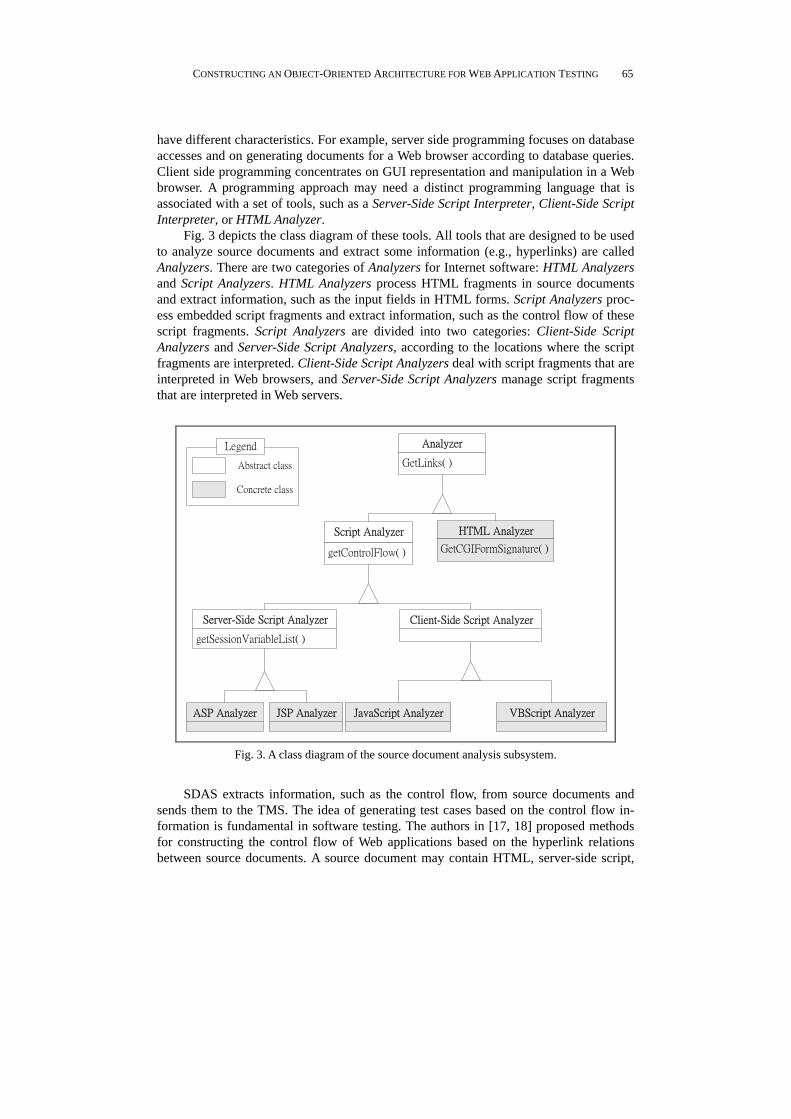
have different characteristics. For example, server side programming focuses on database accesses and on generating documents for a Web browser according to database queries. Client side programming concentrates on GUI representation and manipulation in a Web browser. A programming approach may need a distinct programming language that is associated with a set of tools, such as a Server-Side Script Interpreter, Client-Side Script Interpreter, or HTML Analyzer.
Fig. 3 depicts the class diagram of these tools. All tools that are designed to be used to analyze source documents and extract some information (e.g., hyperlinks) are called Analyzers. There are two categories of Analyzers for Internet software: HTML Analyzers and Script Analyzers. HTML Analyzers process HTML fragments in source documents and extract information, such as the input fields in HTML forms. Script Analyzers proc-ess embedded script fragments and extract information, such as the control flow of these script fragments. Script Analyzers are divided into two categories: Client-Side Script Analyzers and Server-Side Script Analyzers, according to the locations where the script fragments are interpreted. Client-Side Script Analyzers deal with script fragments that are interpreted in Web browsers, and Server-Side Script Analyzers manage script fragments that are interpreted in Web servers.
GetLinks( )
Analyzer
GetCGIFormSignature( )
HTML Analyzer
getControlFlow( )
Script Analyzer
Client-Side Script Analyzer
getSessionVariableList( )
Server-Side Script Analyzer
JSP AnalyzerASP Analyzer JavaScript Analyzer VBScript Analyzer
Abstract class
Concrete class
Legend
Fig. 3. A class diagram of the source document analysis subsystem.
SDAS extracts information, such as the control flow, from source documents and
sends them to the TMS. The idea of generating test cases based on the control flow in-formation is fundamental in software testing. The authors in [17, 18] proposed methods for constructing the control flow of Web applications based on the hyperlink relations between source documents. A source document may contain HTML, server-side script,

JI-TZAY YANG, JIUN-LONG HUANG, FENG-JIAN WANG AND WILLIAM CHENG-CHUNG CHU
66
and client-side script all at the same time. Analyzers are designed to extract hyperlinks in three steps. Fig. 4 depicts an SDAS architecture that can construct the control flow of Web applications. The analysis process contains the following steps:
1. Source documents are sent to a Server-Side Script Analyzer, which analyzes the server-side script (i.e. ASP) fragments, which are then sent to a Server-Side Script Interpreter, which interprets the server-side script fragments.
2. The interpreted source documents are sent to a Client-Side Script Analyzer which analyzes the client-side script (i.e. JavaScript) fragments, which are then sent to Cli-ent-Side Script Interpreter, which interprets the client-side script fragments.
3. The source documents interpreted in step 2 are sent to an HTML Analyzer which analyzes the HTML fragments.
4. All hyperlinks extracted in steps 1, 2, and 3 are sent to a Control Flow Builder which constructs the control flow of the Web application, which is then stored in the TMS.
ASP
Analyzer
JSP
Analyzer
JavaScript
Analyzer
VBScript
Analyzer
HTML
Analyzer
Server Side
Script
Interpreter
Client Side
Script
Interpreter
Control Flow Builder
Source
Documents
Test
Management
Subsystem
Document Analysis Subsystem
Client Side
Script Analyzer
Server Side
Script Analyzer
Fig. 4. Source document analysis subsystem.
CONSTRUCTING AN OBJECT-ORIENTED ARCHITECTURE FOR WEB APPLICATION TESTING
67
3.3 The Test Management Subsystem (TMS)
Testing (and validation) deals with many artifacts that may be created during earlier development phase(s) or even the validation phase [11]. Compared with traditional soft-ware, Web applications play additional roles with respect to Web servers and browsers, and have additional control mechanisms, such as cookies and sessions. Therefore, testing of Web applications is diverse (and might be more complicated than) than testing of traditional software since test artifact management (e.g., manipulation of test cases) is more important. The TMS serves as a warehouse for other subsystems and provides test-ing artifact management as it contains an Application Information Repository and a Test Suite/Case Repository, which both have a manager that handles repository manipulation.
A Web application testing model defined in [17] is adopted to represent and store the control and data flow of Web applications in the Application Information Repository. The Test Suite/Case Repository stores test suites (and cases) that include test data, execu-tion paths, execution results, and test reports. The TMS provides a set of repository ac-cess interfaces and separates the interfaces from their implementations. Other subsystems can create, manipulate, delete and query repositories by means of these access interfaces. The TMS Manager pattern [10] is designed to achieve this goal.
Fig. 5 depicts the TMS architecture based on the Manager pattern. The client sub-system sends request messages to the Test Suite/Case Manager, which then loads or cre-ates the Test Case corresponding objects, and manipulate the test suites or cases. The client subsystem can directly employ the Test Case object after manipulation. The client subsystem does not need modification when testers change the implementation of the Test Suite/Case Repository because the two are not connected. The Application Informa-tion Manager is implemented in a manner similar to that for the Test Suite/Case Man-ager.
The test process becomes too time-consuming and complicated to be performed by only one tester as the testing environments expand. Therefore, the TMS adopts the Bodyguard pattern [10] to provide shared object access, fine-grained control of access restrictions, and dynamic access rights manipulation.
3.4 The Test Development Subsystem (TDS)
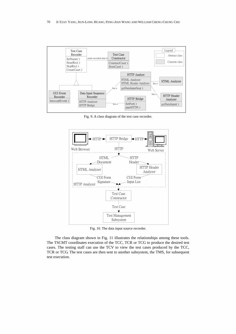
The TDS allows testers to manipulate test suites and cases by automatically gener-ating test cases or constructing them manually based on the application information gen-erated by the SDAS. The test suites and cases are stored in the TMS. The TDS sends the user’s request to the TMS for execution after receiving these requests. The TDS contains five tools: a Test Case Generator (TCG), a Test Suite/Case Maintenance Tool (TSCMT), a Test Case Recorder (TCR), a Test Case Constructor (TCC), and a Test Case Viewer (TCV).
The TCG can automatically generate test cases under a testing criterion, such as all-statement or all-branch coverage for Web applications. The Test Data Definition Grammar is a context-free grammar that is designed to enable testers to specify the for-mat or pattern of test data. The test data for these test cases are generated according to the specifications. Fig. 6 presents an example fragment of the Test Data Definition Grammar. All non-terminal symbols start with $. In this example, u8417805 and U8217506 are two of the candidate test data generated by the grammar defined in the example.

JI-TZAY YANG, JIUN-LONG HUANG, FENG-JIAN WANG AND WILLIAM CHENG-CHUNG CHU
68
task
Client
Subsystem
collection of Test
Cases
create( )
search( )
retire( )
Test Suite/Case
Managercreates,destroys
retrivevs
test casescollection of Test
Steps
initialize( )
destroy( )
gotoFirstStep( )
nextStep( )
Test Case
test data
getUrl( )
getTestData( )
Test Stepcontains
use
task
Client
Subsystem
collection of
Application
Information
create( )
search( )
retire( )
Application
Information
Managercreates,destroys
retrivevs
test cases
collection of
information
initialize( )
destroy( )
gotoFirstStep( )
nextStep( )
Application
Information
data
getEntryNode( )
Control Flowcontains
use
data
getVarInfo( )
Data Flowcontains
Fig. 5. The test management subsystem.
$StudentID�$IDPrefix+$Num+$Num+$Num+$Num+$Num+$Num+$Num $IDPrefix�u|U $Num�0|1|2|3|4|5|6|7|8|9
Fig. 6. An example fragment of the test data definition language.
There are at least two problems in automatic test case generation: the test cases may
not be practical, and they may not cover all significant scenarios. Fig. 7 shows an exam-ple control flow for a sample Web application. Three test cases may be generated based on the stated coverage criterion as illustrated in Fig. 8. Test case 3 is impractical since the test data in N1 may cause N4 to not contain a hyperlink to N5. Moreover, an N1�N4�N3�N5 execution path is not covered in the generated test cases even though it may be a significant and practical scenario.
The TSCMT includes functions which enable it to help the tester manipulate the test suites/cases so as to solve the problem introduced by the TCG. These functions include test suite/case editing, deleting, and reviewing. The testers can review these test cases using a TCV, a graphic tool used to view the test cases, and modify or even delete these test cases using the TSCMT.
The TCR semi-automatically creates test cases in order to defeat the weakness of the TCG mentioned above. A desired test case, which is not generated by the TCG, can be created with the TCR as follows. When the tested Web application is executed, the TCR can record the execution scenario. The execution steps in the recorded scenario are then translated into test cases. Testers can thus utilize the Web browser to acquire these test cases.

CONSTRUCTING AN OBJECT-ORIENTED ARCHITECTURE FOR WEB APPLICATION TESTING
69
N1
N5
N3N2 N4
Fig. 7. An example control flow for a web application.
Test Cases No. Execution Path
1 N1�N2�N5 2 N1�N3�N5 3 N1�N4�N5
Fig. 8. The test paths generated from the control flow shown in Fig. 7.
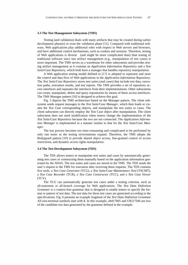
There are at least two TCR subclasses: the Data Input Sequence Recorder (DISR) and the GUI Event Recorder (GUIER). Fig. 9 depicts a TCR’s class diagram. The DISR tracks the execution sequences and data fields entered by the testers in HTML forms, and it also constructs the test cases. The DISR contains two modules, the HTTP Bridge and HTTP Analyzer, and its architecture is depicted in Fig. 10. The HTTP Bridge captures the HTTP communication between the Web server and browser. The captured communication is analyzed by the HTTP Analyzer which constructs the test cases. The HTTP Header Ana-lyzer analyzes the header of the HTTP communication in order to extract the values of the HTML form inputs. The HTML Analyzer analyzes the HTML part in order to extract information related to the HTML form (e.g., the field names in the HTML form). The HTTP Header Analyzer and HTML Analyzer then send the analysis results to the Test Case Constructor, which constructs the test cases.
The author in [19] noted that more applications have been built with complex graphical user interfaces (GUI), and that testing of GUI-based systems is now vital to validating the behavior of the GUI. Web applications are treated as GUI-based systems only when the GUI behavior is of concern. A GUI Event Recorder(GUIER) records the user-caused GUI events related to Web applications (mouse movements, button clickings, etc.) by intercepting the application and operating system events and constructing the test cases. The GUIER can also test the GUI behavior about ActiveX controls and Java Ap-plets. The recorded execution information of the tested Web application is gathered by the DISR or the GUIER and stored in a format recognizable by the TCC for subsequent test case refinement. The TCC is an editing tool that can modify a test case, refine exist-ing test cases, and manually create test cases. It can also solve the second problem intro-duced by the TCC. Testers can manually develop test cases by writing test scripts using the TCC if they are familiar with the Web applications and testing environment.
JI-TZAY YANG, JIUN-LONG HUANG, FENG-JIAN WANG AND WILLIAM CHENG-CHUNG CHU
70
SetName( )
StrartRec( )
StopRec( )
CreateCase( )
Test Case
Recorder
HTTP Analyzer
HTTP Bridge
Data Input Sequence
Recorder
InterceptEvent( )
GUI Event
Recorder
SetPort( )
pipeHTTP( )
HTTP Bridge
HTML Analyzer
HTML Header Analyzer
getDataInputSeq( )
HTTP Analyer
has a
has a
getDataInput( )
HTTP Header
Analyzer
has a
Abstract class
Concrete class
Legend
ConstructCase( )
StoreCase( )
Test Case
Constructorsends recorded data to
HTML Analyzerhas a
Fig. 9. A class diagram of the test case recorder.
Web Browser Web Server
HTTPHTTP
HTTP
HTTP
Header
HTML
Document
CGI Form
Signature
CGI Form
Input List
HTTP Bridge
HTTP Header
AnalyzerHTML Analyzer
Test Case
Constructor
Test Case
HTTP Analyzer
Test Management
Subsystem
Fig. 10. The data input source recorder.
The class diagram shown in Fig. 11 illustrates the relationships among these tools. The TSCMT coordinates execution of the TCC, TCR or TCG to produce the desired test cases. The testing staff can use the TCV to view the test cases produced by the TCC, TCR or TCG. The test cases are then sent to another subsystem, the TMS, for subsequent test execution.
CONSTRUCTING AN OBJECT-ORIENTED ARCHITECTURE FOR WEB APPLICATION TESTING
71
LoadSuite( )
GenTestCases( )
Store( )
Test Case
Generator
ListAllSuite( )
NewSuite( )
DeleteSuite( )
ListCaseFromSuite( )
NewTestCase( )
EditTestCase( )
DeleteTestCase( )
ViewTestCase( )
Test Suite/Case
Maintenance Tool
InsertTestStep( )
AppendTestStep( )
Store( )
Test Case
Composer
SetName( )
StartRec( )
StopRec( )
CreateCases( )
Test Case
Recorder
Invoke
Invoke
Invoke
Test Management
Subsystem
Access
Access
Access
Test Development Subsystem
ViewTestCase( )
Test Case Viewer
Invoke
Access
Fig. 11. A class diagram of the test development subsystem.
3.5 The Test Execution Subsystem (TES)
The Test Case Executor (TCE) executes test cases automatically or manually by
following the parameters specified by the tester and retrieving the appropriate informa-tion from the Test Suite/Case Repository. Each execution is checked by either the Test Oracle or the tester in order to determine whether the execution matches the Web appli-cation specifications. Test data in normal software testing environments are input into tested software via a standard input (stdin). However, there are two kinds of test data input for Web applications: user-input data and user-caused GUI events. The Data Filler and GUI Event Generator are designed to automatically input test data and send GUI events into the Web applications.
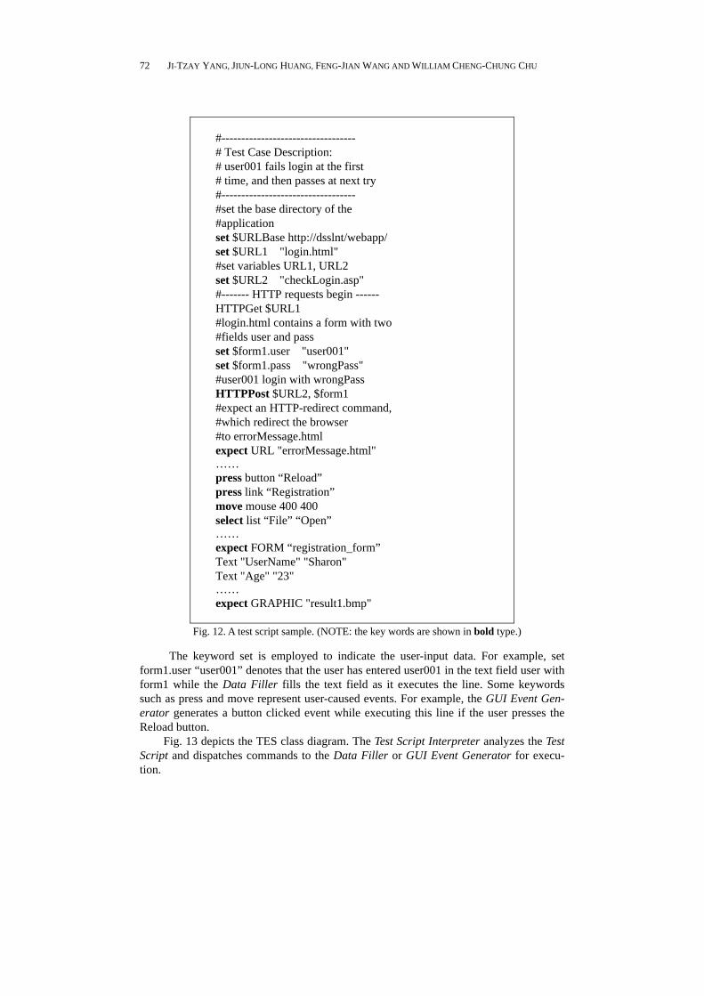
Fig. 12 shows a test script sample. The grammar of the sample script defines the ac-tions: (1) input of data into HTML forms, such as text boxes, text areas, list boxes, toggle buttons; (2) verification of the Web server’s response, such as a URL, text and image contained in the HTML response. To obtain details about GUI operations that are indi-rectly related to the HTML form of the Web application, testers can import traditional GUI testing tools and augment the testing script’s grammar to enhance Web application testing environments.
JI-TZAY YANG, JIUN-LONG HUANG, FENG-JIAN WANG AND WILLIAM CHENG-CHUNG CHU
72
#---------------------------------- # Test Case Description: # user001 fails login at the first # time, and then passes at next try #---------------------------------- #set the base directory of the #application set $URLBase http://dsslnt/webapp/ set $URL1 "login.html" #set variables URL1, URL2 set $URL2 "checkLogin.asp" #------- HTTP requests begin ------ HTTPGet $URL1 #login.html contains a form with two #fields user and pass set $form1.user "user001" set $form1.pass "wrongPass" #user001 login with wrongPass HTTPPost $URL2, $form1 #expect an HTTP-redirect command, #which redirect the browser #to errorMessage.html expect URL "errorMessage.html" …… press button “Reload” press link “Registration” move mouse 400 400 select list “File” “Open” …… expect FORM “registration_form” Text "UserName" "Sharon" Text "Age" "23" …… expect GRAPHIC "result1.bmp"
Fig. 12. A test script sample. (NOTE: the key words are shown in bold type.)
The keyword set is employed to indicate the user-input data. For example, set form1.user “user001” denotes that the user has entered user001 in the text field user with form1 while the Data Filler fills the text field as it executes the line. Some keywords such as press and move represent user-caused events. For example, the GUI Event Gen-erator generates a button clicked event while executing this line if the user presses the Reload button.
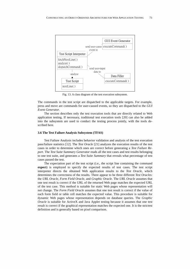
Fig. 13 depicts the TES class diagram. The Test Script Interpreter analyzes the Test Script and dispatches commands to the Data Filler or GUI Event Generator for execu-tion.
CONSTRUCTING AN OBJECT-ORIENTED ARCHITECTURE FOR WEB APPLICATION TESTING
73
nextLine( )
Test Script
fetchNextLine( )
analyze( )
dispatchCommand( )
Test Script Interpreter
executeCommand( )
GUI Event Generator
executeCommand( )
Data Filler
send user-cause
event to
send user-input
data toanalyze
Fig. 13. A class diagram of the test execution subsystem.
The commands in the test script are dispatched to the applicable targets. For example, press and move are commands for user-caused events, so they are dispatched to the GUI Event Generator.
The section describes only the test execution tools that are directly related to Web application testing. If necessary, traditional test execution tools [20] can also be added into the subsystem are used to conduct the testing process jointly, with the tools de-scribed here.
3.6 The Test Failure Analysis Subsystem (TFAS)
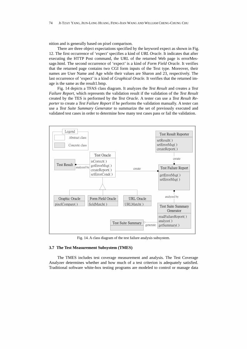
Test Failure Analysis includes behavior validation and analysis of the test execution pass/failure statistics [12]. The Test Oracle [21] analyzes the execution results of the test cases in order to determine which ones are correct before generating a Test Failure Re-port. The Test Suite Summary Generator reads all the test cases and test results belonging to one test suite, and generates a Test Suite Summary that reveals what percentage of test cases passed the test.
The expectation part of the test script (i.e., the script line containing the command expect) is employed to specify the expected results of test cases. The test script interpreter directs the obtained Web application results to the Test Oracle, which determines the correctness of the results. There appear to be three different Test Oracles: the URL Oracle, Form Field Oracle, and Graphic Oracle. The URL Oracle assumes that one test result is correct if the URL of the returned Web page matches the expected URL of the test case. This method is suitable for static Web pages whose representation will not change. The Form Field Oracle assumes that one test result is correct if the value of each form field or table cell matches the expected value. This procedure is suitable for dynamic Web pages whose representation depends on database queries. The Graphic Oracle is suitable for ActiveX and Java Applet testing because it assumes that one test result is correct if the graphical representation matches the expected one. It is the strictest definition and is generally based on pixel comparison.
JI-TZAY YANG, JIUN-LONG HUANG, FENG-JIAN WANG AND WILLIAM CHENG-CHUNG CHU
74
nition and is generally based on pixel comparison. There are three object expectations specified by the keyword expect as shown in Fig.
12. The first occurrence of ‘expect’ specifies a kind of URL Oracle. It indicates that after executing the HTTP Post command, the URL of the returned Web page is errorMes-sage.html. The second occurrence of ‘expect’ is a kind of Form Field Oracle. It verifies that the returned page contains two CGI form inputs of the Text type. Moreover, their names are User Name and Age while their values are Sharon and 23, respectively. The last occurrence of ‘expect’ is a kind of Graphical Oracle. It verifies that the returned im-age is the same as the result1.bmp.
Fig. 14 depicts a TFAS class diagram. It analyzes the Test Result and creates a Test Failure Report, which represents the validation result if the validation of the Test Result created by the TES is performed by the Test Oracle. A tester can use a Test Result Re-porter to create a Test Failure Report if he performs the validation manually. A tester can use a Test Suite Summary Generator to summarize the set of previously executed and validated test cases in order to determine how many test cases pass or fail the validation.
isCorrect( )
getErrorMsg( )
createReport( )
setErrorCond( )
Test Oracle
getErrorMsg( )
setErrorMsg( )
Test Failure Report
readFailureReport( )
analyze( )
getSummary( )
Test Suite Summary
Generator
Test Suite Summary
create
analyzed by
URLMatch( )
URL Oracle
fieldMatch( )
Form Field Oracle
pixelCompare( )
Graphic Oracle
generate
Abstract class
Concrete class
Legend
Test Resultanalyzed by
setResult( )
setErrorMsg( )
createReport( )
Test Result Reporter
create
Fig. 14. A class diagram of the test failure analysis subsystem.
3.7 The Test Measurement Subsystem (TMES)
The TMES includes test coverage measurement and analysis. The Test Coverage Analyzer determines whether and how much of a test criterion is adequately satisfied. Traditional software white-box testing programs are modeled to control or manage data
CONSTRUCTING AN OBJECT-ORIENTED ARCHITECTURE FOR WEB APPLICATION TESTING
75
flow, and the coverage is the percentage of statements or branches that a set of test cases covers if the all-statements or all-branches criterion are employed. The author in [17] modeled Web pages or programming modules as statements and modeled hyperlinks as execution flow in traditional software testing. The coverage criterion in traditional soft-ware testing can also be applied here.
Test coverage can be defined in an inter-module or intra-module manner in Web ap-plications. Each Web page and programming module is modeled as statements when the inter-module definition is applied. Test coverage should also consider the control flows of the server-side or client-side script fragments inside Web pages and programming modules according to the intra-module definition.
Fig. 15 depicts the structure of the TMES. The test coverage of the Web application is computed by the Test Coverage Analyzer (TCA) based on the following two factors: (1) the test case execution history, collected by the TES, is information regarding the mod-ules/statements/branches executed for each test cases; (2) the information, provided by the SDAS, includes, for example, control-flow information consisting of modules, state-ments and branches contained in the Web application. In object-oriented Web application testing, information about object-relations and object-states can be added in to improve above coverage computation. This is done by constructing tools in the SDAS and TES that keep track of the object-relation and states information of the application.
Test Case
Execution
History
Application
Information
createReport( )
Test Coverage
Analyzer Test Coverage
Report
analyzed by
analyzed by
create
Fig. 15. A Class Diagram of the Test Measurement Subsystem.
4. APPLYING THE ARCHITECTURE
A Web application testing environment prototype was implemented based on the Web application testing architecture to establish its practicality as discussed in Section 2.4. Fig. 16 is an overview of the Web application testing environment. The tools inside the tool set are controlled by the WWW control interface, to which authorized Web browsers can connect via HTTP. Although the sample testing environment does not apply all of the testing artifacts in the architecture, it can perform fundamental testing tasks on Web applications. To apply the architecture, the Web application testing environment constructors can divide the construction process into five phases: (1) planning, (2) selec-tion, (3) specialization, (4) integration, and (5) implementation.

JI-TZAY YANG, JIUN-LONG HUANG, FENG-JIAN WANG AND WILLIAM CHENG-CHUNG CHU
76
Fig. 16. The web application testing environment.
Planning The tasks that the sample testing environment should perform include: (1) testing
Web applications written in Microsoft ASP, (2) construction and composition of test cases, (2) execution of test cases, and (3) generation of test failure and coverage reports. Both the tested application and the testing environment are operated under the Web en-vironment. The sample environment only needs to provide semi-automatic and manual test case construction. In addition, the control flow information of the source program is needed and aids the test case design. Therefore, the six subsystems SDAS, TDS, TMS, TES, TFAS, and TMES are all employed.
Selections
The Active Server Page analyzer in the SDAS is selected and used to analyze the tested Web application, which consists of *.asp files. The TCR, TCC, and TSCMT from the TDS are selected since the sample testing environment supports semi-automatic and manual test case generation and test case maintenance. The Test Script Interpreter and the Data Filler from the TES are selected because the sample testing environment sup-ports user-input data as input while test cases are being executed. The TCA in the TMES is used to compute the test coverage. The Test Result Composer and the Test Suite Sum-mary Generator from the TFAS were favored because the sample testing environment supports user determination of the correctness of test cases while the test failure report is being generated. Finally, the Test Suite/Case Repository, Application Information Re-pository, and the manager from the TMS are used to manage the testing artifacts.
CONSTRUCTING AN OBJECT-ORIENTED ARCHITECTURE FOR WEB APPLICATION TESTING
77
Specialization After the domain components from the subsystems are selected, they are altered to
fit the demands of the sample testing environment. For example, the Test Suite/Case Re-pository and Application Information Repository are stored in a file system instead of a database system for the sake of simplicity.
Integration
The interfaces of each component and the communication among these components can be defined since all domain components have been specialized. Incompatible inter-faces can be modified, or an Adapter [9] pattern can be applied to convert the interfaces of one component into the interfaces expected by another component if some compo-nents are incompatible.
Implementation
A concrete design architecture is built after the above phases are completed, and it is implemented based on the specification of each component as well as through commu-nication among components. The details of the finished sample testing environment are given in the following subsection. The whole environment need not be implemented from scratch in most cases as some domain components can be employed in the selection phase if they are available. Moreover, the interface compatibility of the newly developed components can be checked against that of existing components in the integration phase.
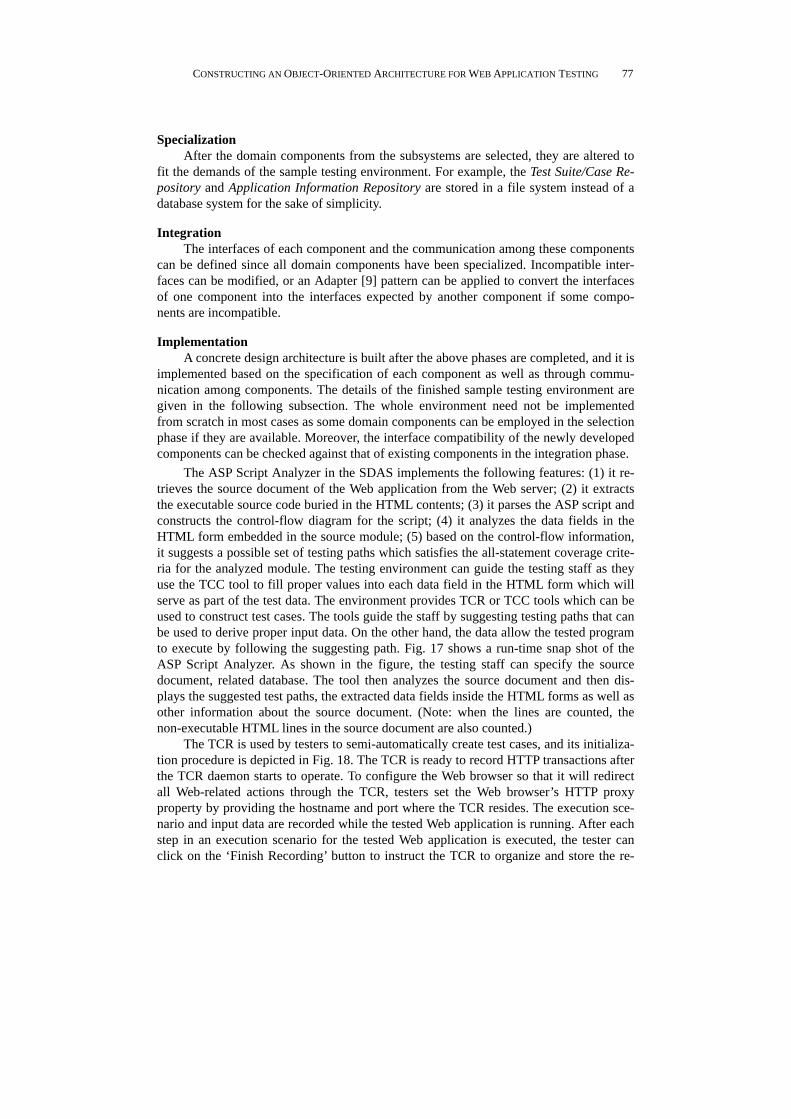
The ASP Script Analyzer in the SDAS implements the following features: (1) it re-trieves the source document of the Web application from the Web server; (2) it extracts the executable source code buried in the HTML contents; (3) it parses the ASP script and constructs the control-flow diagram for the script; (4) it analyzes the data fields in the HTML form embedded in the source module; (5) based on the control-flow information, it suggests a possible set of testing paths which satisfies the all-statement coverage crite-ria for the analyzed module. The testing environment can guide the testing staff as they use the TCC tool to fill proper values into each data field in the HTML form which will serve as part of the test data. The environment provides TCR or TCC tools which can be used to construct test cases. The tools guide the staff by suggesting testing paths that can be used to derive proper input data. On the other hand, the data allow the tested program to execute by following the suggesting path. Fig. 17 shows a run-time snap shot of the ASP Script Analyzer. As shown in the figure, the testing staff can specify the source document, related database. The tool then analyzes the source document and then dis-plays the suggested test paths, the extracted data fields inside the HTML forms as well as other information about the source document. (Note: when the lines are counted, the non-executable HTML lines in the source document are also counted.)
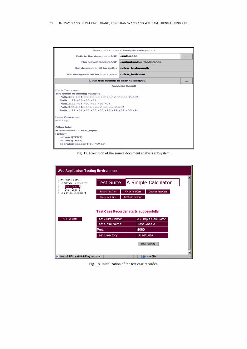
The TCR is used by testers to semi-automatically create test cases, and its initializa-tion procedure is depicted in Fig. 18. The TCR is ready to record HTTP transactions after the TCR daemon starts to operate. To configure the Web browser so that it will redirect all Web-related actions through the TCR, testers set the Web browser’s HTTP proxy property by providing the hostname and port where the TCR resides. The execution sce-nario and input data are recorded while the tested Web application is running. After each step in an execution scenario for the tested Web application is executed, the tester can click on the ‘Finish Recording’ button to instruct the TCR to organize and store the re-
JI-TZAY YANG, JIUN-LONG HUANG, FENG-JIAN WANG AND WILLIAM CHENG-CHUNG CHU
78
Fig. 17. Execution of the source document analysis subsystem.
Fig. 18. Initialization of the test case recorder.
CONSTRUCTING AN OBJECT-ORIENTED ARCHITECTURE FOR WEB APPLICATION TESTING
79
corded data. The tester needs to provide an identifier and testing description for the re-corded test case. The recorded execution steps can be directly replayed during the test case execution period. The recorded execution steps can also be modified by the TCC if necessary.
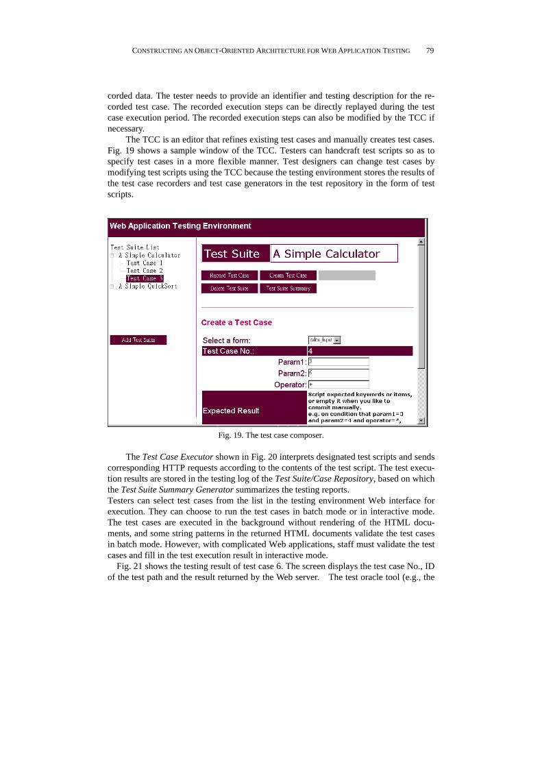
The TCC is an editor that refines existing test cases and manually creates test cases. Fig. 19 shows a sample window of the TCC. Testers can handcraft test scripts so as to specify test cases in a more flexible manner. Test designers can change test cases by modifying test scripts using the TCC because the testing environment stores the results of the test case recorders and test case generators in the test repository in the form of test scripts.
Fig. 19. The test case composer.
The Test Case Executor shown in Fig. 20 interprets designated test scripts and sends
corresponding HTTP requests according to the contents of the test script. The test execu-tion results are stored in the testing log of the Test Suite/Case Repository, based on which the Test Suite Summary Generator summarizes the testing reports. Testers can select test cases from the list in the testing environment Web interface for execution. They can choose to run the test cases in batch mode or in interactive mode. The test cases are executed in the background without rendering of the HTML docu-ments, and some string patterns in the returned HTML documents validate the test cases in batch mode. However, with complicated Web applications, staff must validate the test cases and fill in the test execution result in interactive mode. Fig. 21 shows the testing result of test case 6. The screen displays the test case No., ID of the test path and the result returned by the Web server. The test oracle tool (e.g., the

JI-TZAY YANG, JIUN-LONG HUANG, FENG-JIAN WANG AND WILLIAM CHENG-CHUNG CHU
80
Fig. 20. The test case executor.
Fig. 21. The test execution result viewer.
Graphic oracle, form-field oracle and URL oracle) in the TFAS subsystem also con-tributes information to the testing result by comparing the expected content with the ac-tual one. In the example, test case No.6 defines a text oracle ‘45+15=60’, so the text ora-cle tool searches the result for the text string ‘45+15=60’ to verify the correctness of the

CONSTRUCTING AN OBJECT-ORIENTED ARCHITECTURE FOR WEB APPLICATION TESTING
81
test case. The figure shows that the text ‘45+15=60’ is found and is indicated by an arrow. The fact that the test oracle for test case No. 6 is correct is also displayed on the screen.tem).
Fig. 22 displays the test report produced by the Test Suite Summary Generator, which is a tool selected from the TFAS subsystem. In the test report, testing staff can examine the test result of each test case and compute the statement-level coverage of executed or selected test cases. The coverage percentage shown in the report is contrib-uted by the TCA tool of the TMES subsystem. The TCA utilizes control-flow information from the ASP script analyzer of the SDAS as well as the log of executed statements kept by the Application Information Repository in the TMS to compute the coverage percent-age.
Fig. 22. The test suite summary generator.
5. CONCLUSIONS
This work has proposed a reusable architecture which can be used to construct a Web application testing environments by extending an well-evaluated architecture and applying some design patterns. With the architecture, an Web application testing envi-ronment can be constructed by reusing existing tools and constructing new tools under the following six subsystems: SDAS (source document analysis subsystem), TMS (test management subsystem), TDS (test development subsystem), TES (test execution sub-system), TFAS (test failure analysis subsystem) and TMES (test measurement subsys-tem).
The Web application testing processes (e.g., test case design and execution) can be conducted by employing the six subsystems contained within the architecture. To adapt

JI-TZAY YANG, JIUN-LONG HUANG, FENG-JIAN WANG AND WILLIAM CHENG-CHUNG CHU
82
to the Web’s characteristics, several supplementary tools for testing Web applications have been also proposed in this work, e.g., the test case recorder and player for Web ap-plications. In addition, a tool integration interface for each subsystem is designed and provided as shown in the class diagram of each subsystem. Constructors of software testing environments for Web applications can utilize the architecture and reuse the pre-pared tools in each subsystem to achieve their goals without designing them from scratch.
To demonstrate its overall viability and practicality, a prototype Web application testing environment has been built on the proposed architecture. The prototype contains typical and necessary testing tools to achieve the required functionality in each subsys-tem. In a prototype testing environment, the SDAS can analyze an application written in Microsoft ASP. The TMS and the TDS work together to guide the testing staffs as they develop test cases. The effort required to construct test cases for Web applications is re-duced by the prototype environment’s ability to record application operating procedures and data input in HTML Form via an Web browser. The TES and TFAS help the testing staff execute test cases and verify the execution result. The TMES produces a test sum-mary. The TES and TFAS can aid testing execution and reduce the effort required of the testing staffs to automate application data input as well as result checking procedures in the Web environments.
Because the scope of and techniques of employed Web application development are still evolving, the Web application testing environment need to be upgraded when new elements are added during Web application development. For example, a source codes analyzer for Web applications may need to be used to separate program statements exe-cuted by the Web server and browser that are mixed together in one source file. It may be necessary to use the program analysis tools to analyze the of hyper-links navigation in the Web application as well as the control-flow or data-flow buried in the program state-ments. However, the architecture of the traditional software testing environment can still be used to Web application testing after minor adaptation is done and additional en-hanced tools are provided based on the integration interfaces defined in each subsystem.
ACKNOWLEDGEMENTS
The authors would like to thank Chunghwa Telecom Laboratories for financially supporting this research under Contract No. TL-89-8701.
REFERENCES
1. P. Fraternali, “Tools and approaches for developing data-intensive web applications: a survey,” ACM Computing Surveys, Vol. 31, 1999, pp. 227-263.
2. B. Fromme, “Web software testing – challenges and solutions,” InterWorks 98 Con-ference, 1998. (Also available in http://www.interex.org/conference/sessions/home. html)
3. Software Methods and Tools Company, “A collection of testing and testing manage-ment tools,” in http://www.methods-tools.com/tools/testing.html.
4. Sun Microsystems, “SunTest suite,” in http://www.sun.com/suntest. 5. Softbridge Inc., “Web Analyst,” in http://www.softbridge.com.

CONSTRUCTING AN OBJECT-ORIENTED ARCHITECTURE FOR WEB APPLICATION TESTING
83
6. Mercury Interactive Corp., “Powerful test automation for enterprise – Mercury Inter-active’s WinRunner,” in http://secure.merc-int.com/products/winrunner5/.
7. Mercury Interactive Corp., “Visual web site management – Mercury interactives’s astra sitemanager,” in http://www.merc-int.com/products/astrasmguide.html.
8. Rational Software, “Visual test 4.0 white paper,” in http://www.rational.com/pro- ducts/visual_test/prodinfo/whitepapers/dynamic.jtmpl?doc_key=100464.
9 E. Gamma, R. Helm, R. Johnson, and J. Vlissides, Design Patterns: Elements of Re-usable Object-Oriented Software, Addison-Wesley, 1994.
10. R. Martin, D. Riehle, and F. Buschmann, Pattern Languages of Program Design 3, Addison-Wesley, 1998.
11. D. J. Richardson, “TAOS: testing with analysis and oracle support,” in Proceedings of ACM SIGSOFT International Symposium on Software Testing and Analysis (ISSTA 94), 1994, pp. 138-153.
12. N. S. Eickelmann and D. J. Richardson, “An evaluation of software test environment architectures,” International Conference on Software Engineering (ICSE96), 1996, pp. 353-364.
13. C. W. Krueger, “Software reuse,” ACM Computing Surveys, 1992, pp. 131-183. 14. R. V. Binder, “Testing object-oriented software: a survey,” Software Testing, Verifica-
tion and Reliability, Vol. 6, 1996, pp. 125-252. 15. D. C. Kung, J. Gao, P. Hsia, Y. Toyoshima, C. Chen, Y.-S. Kim, and Y.-K. Song,
“Developing an object-oriented software testing and maintenance environment,” Communications of the ACM, Vol. 38, 1995, pp. 75-87.
16. D. C. Kung, P. Hsia, and J. Gao, Testing Object-Oriented Software, IEEE Computer Society Press, Los Alamitos, California, 1998.
17. J.-T. Yang, J.-L. Huang, and F.-J. Wang, “A tool set to support web application test-ing,” in Proceedings of the International Computer Symposium (ICS98), 1998.
18. C.-L. Hsu and F.-J. Wang, “A web database application model for software mainte-nance,” Master Thesis, Dept. of Computer Science and Information Engineering, Na-tional Chiao-Tung University, 1998.
19. T. Ostrand, A. Anodide, H. Foster, and T. Goradia, “A visual test development envi-ronment for GUI systems,” in Proceedings of ACM SIGSOFT International Sympo-sium on Software Testing and Analysis (ISSTA 98), 1998, pp. 82-92.
20. M. Fewster and D. Graham, Effective Use of Test Execution Tools, Addison-Wesley, Harlow, Essex, U.K., 1999.
21. B. Beizer, Software Testing Techniques, 2nd ed., Van Nostrand Reinhold, 1990.
Ji-Tzay Yang (楊基載) received his B.S., M.S. and Ph.D. in Computer Science and Information Engineering from National Chiao-Tung University, Hsinchu, Taiwan, in 1993, 1995 and 2000 respectively. From 1996 to 1997, he was an instructor of National Chiao Tung University, where he taught network man-agement and Internet services construction. Since 2000, he has involved in a research project of National Chiao Tung University on an Agent-based workflow system. His research involves software engineering, Internet computing, software process mod-eling and workflow system.
JI-TZAY YANG, JIUN-LONG HUANG, FENG-JIAN WANG AND WILLIAM CHENG-CHUNG CHU
84
Jiun-Long Huang (黃俊龍) received the B.S. and M.S. de-grees in Computer Science and Information Engineering from National Chiao Tung University, Hsinchu, Taiwan, R.O.C., in 1997 and 1999, respectively. He is currently working toward the Ph.D. degree at Electrical Engineering Department in National Taiwan University. His research interests include mobile com-puting, database techniques and software engineering.
Feng-Jian Wang (王豐堅) got his B.S. degree from Na-tional Taiwan University, 1980, and M.S. and Ph.D. degrees from Northwestern University, U.S.A., 1986 and 1988 respectively. He is currently a professor in the Department of Computer Sci-ence and Information Engineering, National Chiao Tung Univer-sity, Hsinchu. His research interests include software engineering, OO & related techniques, the Internet, workflow and agent appli-cations, and distributed software systems.
William Cheng-Chung Chu (朱正忠) received his M.S. and Ph.D. degrees from Northwestern University, Evanston, Illi-nois, in 1987 and 1989 respectively, all in computer science. Since 1998, has been with the Department of Computer and In-formation Science at the TungHai University, Taiwan, where he is now a professor and department head. From 1994 to 1998, he has been an Associate Professor at the Department of Information Engineering at the Feng Chia University, Taiwan. Prior to join-ing the Feng Chia University, he was a research scientist at Soft-ware Technology Center of Palo Alto Research laboratories of
Lockheed Missiles and Space Company, Inc., where he served as a member of Software Reverse Engineering and Software Reuse Projects and a principal investigator of Con-verting Programming Languages to Ada project. He had received special contribution awards from Lockheed both in the year of 1992 and 1993. In 1992, he was a Visiting Scholar to Department of Engineering Economic System at Standford University, where he was involved in projects related to the design and development of Intelligent Knowl-edge Based Expert System. His current research interests include the fields of software re-engineering, maintenance, reuse, software quality, and E-commerce.
![Object-oriented Programming with PHP · Object-oriented Programming with PHP [2 ] Object-oriented programming Object-oriented programming is a popular programming paradigm where concepts](https://img.pdfslide.us/doc/110x75/5e1bb46bfe726d12f8517bf0/object-oriented-programming-with-php-object-oriented-programming-with-php-2-object-oriented.jpg)