Embed Size (px)
Citation preview

Constructal T-shaped ®ns
Adrian Bejan*, Majed Almogbel
Department of Mechanical Engineering and Materials Science, Duke University, Durham, NC 27708-0300, USA
Received 30 March 1999; received in revised form 10 September 1999
Abstract
This paper reports the geometric (constructal) optimization of T-shaped ®n assemblies, where the objective is tomaximize the global thermal conductance of the assembly, subject to total volume and ®n-material constraints.Assemblies of plate ®ns and cylindrical ®ns are considered. It is shown that every geometric feature of the assembly
is delivered by the optimization principle and the constraints. These optimal features are reported in dimensionlessterms for this entire class of ®n assemblies. Corresponding results are developed for more evolved versions of the T-shaped assembly, namely, the tau-shaped assembly where the free ends of the thinner ®ns are bent, the tau-shapedassembly that is narrower than the space allocated to it, and the umbrella-shaped construct containing cylindrical
®ns. The results show that some of the optimized geometrical features are relatively robust, i.e., insensitive tochanges in some of the design parameters. # 2000 Elsevier Science Ltd. All rights reserved.
1. Introduction
Constructal theory is the thought that the geometricform visible in natural ¯ow systems is generated by(i.e., it can be deduced from) a single principle that
holds the rank of law [1]. The constructal law was ®rststated for open (or ¯ow) systems: ``For a ®nite-size sys-tem to persist in time (to live), it must evolve in such away that it provides easier access to the imposed cur-
rents that ¯ow through it''. This statement has twoparts. First, it recognizes the natural tendency ofimposed currents to construct shapes, i.e., paths of op-
timal access through constrained open systems. Thesecond part accounts for the changes (i.e., improve-ments) in these paths, which occur in an identi®able
direction that is aligned with time itself.The formulation of the constructal law refers to an
open system with imposed through ¯ow. If the system
is isolated and initially in a state of internal nonequi-librium, it will create optimal geometric paths for itsinternal currents. The constructal law then is the state-
ment that the isolated system selects and optimizes itsinternal structure (the ¯ow paths) to maximize itsspeed of approach to equilibrium (uniformity, no ¯ow)
[2]. The constructal law was conceived as a purelytheoretical way of accounting for the billions and bil-lions of natural patterns that have been recognizedempirically as ``self-organization'' and ``self-optimiz-
ation'' in systems far from equilibrium.The constructal optimization of paths for internal
currents was ®rst proposed in the context of pure
heat conduction [1], with application to the coolingof heat generating electronics in the limit ofdecreasing dimensions. The constructal method
shows us how to minimize geometrically the thermalresistance between a volume and one point, whenthe total system volume and the volume fractionoccupied by high-conductivity ``channels'' are con-
strained. The application of this heat transfer
International Journal of Heat and Mass Transfer 43 (2000) 2101±2115
0017-9310/00/$ - see front matter # 2000 Elsevier Science Ltd. All rights reserved.
PII: S0017-9310(99 )00283-5
www.elsevier.com/locate/ijhmt
* Corresponding author. Tel.: +1-919-660-5310; fax: +1-
919-660-8963.
E-mail address: [email protected] (A. Bejan).

enhancement method to systems with pure conduc-
tion showed that the optimized architecture has a
tree-shaped skeleton formed by high-conductivity
material. The rest of the material ®lls the interstices,
and generates heat at every point of the given
volume. The tree of high-conductivity channels cap-
tures the heat current generated by the entire
volume, and leads it out of the system through the
root point of the tree structure. The interstices of
the tree channels are equally important: in every
optimized volume element there is a perfect balance
between the resistance through the low-conductivity
Nomenclature
a, b dimensionless parameters, Eqs. (5) and (20)A area [m2]f, f� fractions, Eq. (16)
h heat transfer coe�cient [W mÿ2 Kÿ1]k ®n thermal conductivity [W mÿ1 Kÿ1]L length [m]
m ®n parameter, Eq. (6)q heat current [W]t thickness [m]
T temperature [K]V volume [m3]W width [m]y fraction, Eq. (17)
Greek symbolse small dimensionless numbery dimensionless junction temperature, Eq. (9)
f1 volume fraction of ®n material
Subscripts
f ®n materialm maximized oncemm maximized twice
Superscript( ~) dimensionless variables, Eqs. (4), (10) and (21)
Fig. 1. T-shaped assembly of plate ®ns.
A. Bejan, M. Almogbel / Int. J. Heat Mass Transfer 43 (2000) 2101±21152102

and high-conductivity materials, i.e., a perfect bal-ance between the two ``¯ow regimes''.
The constructal tree is determined completely fromone principle: the minimization of global resistancesubject to size constraints. Constructal trees have been
determined for heat conduction in two dimensions [1]and for ¯uid ¯ow through a heterogeneous porousmedium [3]. The wide applicability of this deterministic
principle to the physics of naturally shaped (organized,optimized) ¯ow systems was discussed in a recentreview [4].
In this paper we extend the constructal method to aclass of systems that transfer heat (between a volumeand one point) through a combination of conductionand convection. The system is the assembly of rigidly
connected ®ns that ®lls a given space, and has a ®xedamount of ®n material. The heat current (input or out-put) touches every point of the volume by convection,
because the volume is bathed by a steady stream of¯uid. This current continues by conduction into thesolid links of the ®n assembly, and makes contact with
the root of the assembly.Individual ®ns and assemblies of ®ns have long been
recognized as e�ective means to augment heat transfer.
The literature on this subject is sizeable, as shown bythe most current reviews [5,6]. The new aspect that iscontributed by the constructal method is the completegeometric optimization of the assembly of ®ns when
the total volume inhabited by the assembly is ®xed. Inorder to illustrate this aspect in the most transparentterms, we apply the constructal method to some of the
simplest assembly types that have been recognized inpractice [5±10].
2. Unidirectional conduction model
Consider the T-shaped assembly of ®ns sketched inFig. 1. Two ``elemental'' ®ns of thickness t0 and lengthL0 serve as tributaries to a stem of thickness t1 and
length L1. The con®guration is two-dimensional, withthe third dimension (W ) su�ciently long in compari-son with L0 and L1. The heat transfer coe�cient h is
uniform over all the exposed surfaces. Speci®ed are thetemperatures of the root (T1) and the ¯uid (T1). Thetemperature at the T junction (T0) is one of theunknowns, and varies with the geometry of the assem-
bly.The objective of the following analysis is to deter-
mine the optimal geometry �L1=L0, t1=t0� that is
characterized by the maximum global thermal conduc-tance q1=�T1 ÿ T1�, where q1 is the heat currentthrough the root section. As in the constructal optimiz-
ation of conduction trees [1], the present optimizationis subjected to two constraints, namely, the totalvolume (i.e., frontal area) constraint,
A � 2L0L1 �constant� �1�
and the ®n-material volume constraint,
Af � 2L0t0 � t1L1 �constant� �2�
The latter can be expressed as the ®n volume fractionf1 � Af=A, which is a constant considerably smallerthan 1.
The analysis that delivers the global conductance asa function of the assembly geometry consists ofaccounting for conduction along the L0 and L1 ®ns,and invoking the continuity of temperature and heat
current at the T junction. For each ®n we use the uni-directional conduction model, the validity of which istested later in Eqs. (13) and (14).
For the two elemental ®ns we used the classicalassumptions [5,6,11] and the solution for a ®n withnon-negligible heat transfer through the tip,
q0kW�T0 ÿ T1�
� a~t 1=20
sinh�a ~L0 ~tÿ1=20 � � �a=2� ~t 1=20 cosh�a ~L0 ~tÿ1=20 �cosh�a ~L0 ~tÿ1=20 � � �a=2� ~t 1=20 sinh�a ~L0 ~tÿ1=20 �
�3�where
� ~L0, ~t0� � �L0, t0�A1=2
�4�
a ��2hA1=2
k
�1=2
�5�
Eq. (3) shows the emergence of the dimensionless par-
ameters �a, ~L0, ~t0� which in¯uence the dimensionless el-emental conductance q0=�kW�T0 ÿ T1��: Note the useof A 1/2 as length scale in the nondimensionalization of
the linear dimensions.The temperature distribution along the stem T(x ),
from the root (x=0) to the junction (x=L1), is
T�x� ÿ T1 � �T1 ÿ T1� cosh�m1x� ��
T0 ÿ T1sinh�m1L1�
ÿ �T1 ÿ T1� cosh�m1L1�sinh�m1L1�
�sinh�m1x� �6�
The ®n parameter m1 � �2h=kt1�1=2 can be expressed asm1L1 � a ~L1=~t
1=21 : Next, we use T(x ) in the equation
for the continuity of heat current at the T0 junction.
ÿkt1W�@T
@x
�x�L1
� 2q0 �7�
which can be arranged in the following dimensionlessform:
A. Bejan, M. Almogbel / Int. J. Heat Mass Transfer 43 (2000) 2101±2115 2103

1ÿ y cosh�a ~L1=~t1=21 �
� 2
�~t0~t1
�1=2
y tanh�a ~L0=~t1=20 � sinh�a ~L1 ~t
1=21 � �8�
Eq. (8) establishes the dimensionless junction tempera-ture as a function of the ®ve dimensionless parametersof the ®n assembly,
y � T0 ÿ T1T1 ÿ T1
� function�a, ~L0, ~t0, ~L1, ~t1� �9�
Finally, the global thermal conductance is obtained byusing Eq. (6) in evaluating the heat current throughthe root, q1 � ÿkt1W�@T=@x�x�0: The result can be
expressed as a dimensionless global conductance,
~q1 �q1
kW�T1 ÿ T1� � a~t 1=21
cosh�a ~L1=~t 1=21 � ÿ y
sinh�a ~L1=~t 1=21 �� �10�
Fig. 2. The double maximization of the overall thermal conductance of the T-shaped construct of Fig. 1.
A. Bejan, M. Almogbel / Int. J. Heat Mass Transfer 43 (2000) 2101±21152104

for which y is provided by Eq. (9). The conductance qÄ1emerges as a function of a, ~L0, ~t0, ~L1 and ~t1: only threeof these parameters are free to vary, because of the
volume and ®n material constraints (1) and (2), whichnow read
2 ~L0~L1 � 1 �11�
f1 � 2 ~L0 ~t0 � ~L1 ~t1 �12�
In the optimization runs we used t1/t0 and L1/L0 asdegrees of freedom, while assigning discrete values tothe parameter a. Fig. 2 shows that qÄ1 can be maxi-mized with respect to both L1/L0 and t1/t0, i.e., with
respect to the external and internal shapes of the ®nassembly. In the ®rst frame of the ®gure the overallconductance is maximized with respect to L1/L0 by
holding t1/t0 constant. The result is the maximized con-ductance qÄ1,m shown in the second frame. This oper-ation is repeated many times for other values of t1/t0,
until qÄ1,m can be maximized for the second time. Theend result of this double maximization is the conduc-tance qÄ1,mm shown in the third frame: here we also
show that we repeated the double maximization pro-cedure for an entire range of a and f1 values, whichare consistent with practical values. For example, in
forced convection to gas ¯ow the order of magnitudeof h is 102 W/m2 K, while the thermal conductivities ofaluminum and copper are of order 102 W/m K. Substi-tuting these values and A 1/2 0 1 cm in Eq. (5) we
obtain a010ÿ1.
3. Optimal T-shaped geometry
Results for the optimal geometry of the T-shapedconstruct can be generated by using the procedure of
Table 1
Numerical examples of optimized T-shaped ®n assemblies
(f1=0.086, a=0.185)
LÄ0 LÄ1 tÄ0 tÄ1 qÄ1
Constructal 1.33 0.376 0.0194 0.091 0.0516
Kraus [5] 0.71 0.689 0.0191 0.086 0.040
Fig. 3. The optimized geometry of the T-shaped construct of Fig. 1.
A. Bejan, M. Almogbel / Int. J. Heat Mass Transfer 43 (2000) 2101±2115 2105
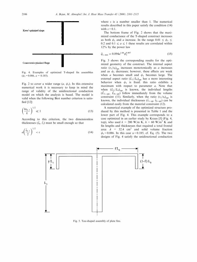
Fig. 2 to cover a wider range (a, f1). In this extensive
numerical work it is necessary to keep in mind therange of validity of the unidirectional conductionmodel on which the analysis is based. The model is
valid when the following Biot number criterion is satis-®ed [12]:�ht0, 1k
�1=2
� 1 �13�
According to this criterion, the two dimensionless
thicknesses (tÄ0, tÄ1) must be small enough so that
a
�~t0, 12
�1=2
< e �14�
where e is a number smaller than 1. The numericalresults described in this paper satisfy the condition (14)
with e=0.1.The bottom frame of Fig. 2 shows that the maxi-
mized conductance of the T-shaped construct increases
as both f1 and a increase. In the range 0.01 R f1 R0.2 and 0.1 R a R 1 these results are correlated within12% by the power law
~q1, mm � 0:894a1:08f0:4071 �15�
Fig. 3 shows the corresponding results for the opti-
mized geometry of the construct. The internal aspectratio �t1=t0�opt increases monotonically as a increasesand as f1 decreases; however, these e�ects are weak
when a becomes small and f1 becomes large. Theexternal aspect ratio �L1=L0�opt has a more interestingbehavior when f1 is ®xed: this ratio exhibits amaximum with respect to parameter a. Note that
when �L1=L0�opt is known, the individual lengths� ~L1, opt, ~L0, opt� follow immediately from the volumeconstraint (11). Similarly, when the ratio �t1=t0�opt is
known, the individual thicknesses � ~t1, opt ~t0, opt� can becalculated easily from the material constraint (12).A numerical example of the optimized structure pro-
duced by this method is presented in Table 1 and thelower part of Fig. 4. This example corresponds to acase optimized in an earlier study by Kraus [5] (Fig. 4,top), who used k = 200 W/m K, h = 60 W/m2 K and
®n lengths and thicknesses that required a total frontalarea A = 32.4 cm2 and solid volume fractionf1=0.086. In this case a=0.185, cf. Eq. (5). The two
designs of Fig. 4 satisfy the unidirectional conduction
Fig. 4. Examples of optimized T-shaped ®n assemblies
(f1=0.086, a=0.185).
Fig. 5. Tau-shaped assembly of plate ®ns.
A. Bejan, M. Almogbel / Int. J. Heat Mass Transfer 43 (2000) 2101±21152106

criterion (14); in both cases the left side of Eq. (14) has
the values a�t0=2�1=2 � 0:018 and a�~t1=2�1=2 � 0:04:Table 1 shows that the constructal-optimized thick-
nesses are nearly the same as in Kraus' design, and
that the geometric di�erences result from the ®n
lengths. In the constructal case the elemental ®ns (L0)
are considerably longer. The main di�erence in the
constructal design is the 29% increase in the global
thermal conductance of the T-shaped assembly.
4. Tau-shaped ®n assemblies
The slenderness of the elemental ®ns in the construc-tal design (Fig. 4) may turn into a disadvantage if the
Fig. 6. The optimized geometry and global performance of tau-shaped ®n assemblies (f1=0.05).
A. Bejan, M. Almogbel / Int. J. Heat Mass Transfer 43 (2000) 2101±2115 2107

design is limited by ¯ow induced vibrations. One wayof extending the applicability of the constructalapproach is to bend the ends of the L0 ®ns, as shown
in Fig. 5. This technique was also described by Kraus[5]. It is particularly important in the constructal de-sign because the bending of the elemental ends allows
the structure to ``®ll better'' its allotted volume. Fillingvolumes in an optimal way (with objective, or purpose,relative to the use of volume-to-point ¯ows) is theessence of the constructal method.
The bending of the L0 ®ns introduces a new dimen-sionless parameter: the fraction f, such that the turnedend is of length (1ÿf )L0, and the portion that is in
thermal contact with the stem is of length fL0. Thefrontal area constraint (1) is replaced by A � 2fL0L1,which means that the dimensionless size constraint is
now
2f ~L0~L1 � 1 �16�
The rest of the mathematical apparatus is the same as
in Section 3. The new parameter f can take values inthe range f� < fR1, where f = 1 represents the T-shaped assembly documented in Section 3, and f� �1ÿ L1=L0 represents the extreme where the bent endwould be as long as the stem, �1ÿ f �L0 � L1: We con-tinue to assume that in each case the ®n thickness is
considerably smaller than the ®n length, and that theunidirectional conduction model [13,14] applies.The important question for the tau-shaped design is
how the f parameter in¯uences the optimal geometry
and performance of the assembly. In other words, it isimportant to determine the thermal-design impact ofincreasing the sti�ness of the assembly. This question
is answered in Fig. 6. We used three f values such thatthe length of the turned end of the L0 ®n is 25, 50 and,®nally, 75% of the stem length L1. Note the graphic
de®nition of the y fraction on Fig. 5, namely f �1ÿ yL1=L0: The T-shaped designs of Fig. 2 correspondto y=0.
The bottom frame of Fig. 6 shows that the overallconductance of the assembly decreases just slightlywhen the ends of the elemental ®ns are bent. The opti-
mized aspect ratios �L1=L0�opt and �t1=t0�opt are alsorelatively insensitive to bending the ends. Fig. 7 showsthe optimized ``tau'' geometry that corresponds to the
case of Fig. 4 when y = 0.25. This design satis®es theunidirectional conduction criterion (14), becausea� ~t0=2�1=2 � 0:18 and a� ~t1=2�1=2 � 0:04:In conclusion, the optimized geometry and perform-
ance of T-shaped ®ns (Section 3) is ``robust'', and canbe used as a good approximation for tau-shaped con-structs that ®ll the same frontal area. The bending of
the elemental ®ns introduces a small thermal conduc-tance penalty, which may be acceptable in view of theincreased sti�ness of the assembly.
5. Narrower tau-shaped assemblies
The tau-shaped con®guration needs an additional
adjustment if several such ®ns are to be mounted onthe same wall (Fig. 8). The uniform-h assumptionmakes it necessary to leave a space between the bent
ends of consecutive elemental ®ns. This means that therectangle circumscribed to each ``tau'' must be some-what narrower than the volume (frontal rectangular
area) allocated and kept constant for that assembly.In Fig. 8 we chose an end-to-end spacing that equals
the spacing between each bent end and its own stem.Since the horizontal portion of the elemental ®n has
Fig. 7. Optimized tau-shaped constructs for f1=0.086 and a=0.185.
Fig. 8. Narrower tau-shaped constructs mounted on the same
wall.
A. Bejan, M. Almogbel / Int. J. Heat Mass Transfer 43 (2000) 2101±21152108

the length L0 ÿ yL1, the distance from the L1 stem tothe vertical side of the allocated frontal area is �3=2���L0 ÿ yL1�: The frontal area constraint isA � 2�3=2��L0 ÿ yL1�L1, which assumes the dimension-less form
3� ~L0 ÿ y ~L1� ~L1 � 1 �17�
Fig. 9 reports the dimensions of the tau-shaped assem-
bly optimized subject to constraint (17). These results
were developed for the same parameters as in Fig. 6:
their purpose is to show that the new constraint (17)
has almost no e�ect on the optimized dimensions of
the assembly.
The same conclusion is drawn from Fig. 7, which
compares the shapes of the tau-shaped assemblies opti-
mized subject to constraints (16) and (17). The conduc-
tion along the narrower tau-shaped ®n shown in Fig. 7
Fig. 9. The optimized geometry and global performance of the narrower tau-shaped assemblies of Fig. 8.
A. Bejan, M. Almogbel / Int. J. Heat Mass Transfer 43 (2000) 2101±2115 2109

is unidirectional because a� ~t0=2�1=2 � 0:02 and
a� ~t1=2�1=2 � 0:04, cf. criterion (14).The two designs of Fig. 7 occupy the same fron-
tal area (the dashed-line rectangle). The two shapes
are nearly the same: the assembly that is narrowerthan its allocated area (the lower drawing) has ashorter and thicker stem than the assembly that
spans the entire width of the area (the upper draw-ing). The maximized thermal conductances of thetop and bottom designs of Fig. 7 are qÄ1=0.0507
and 0.0526, respectively. These values indicate slightdeterioration in performance relative to the optimizeddesign with straight elemental ®ns (Table 1, constructal
design).In conclusion, the optimized assembly is robust not
only with respect to the bending of the tips of the el-
emental (L0) ®ns, but also with respect to the spacingleft between the bent tip and the margin of the frontal¯ow area allocated to the assembly.
6. Umbrellas of cylindrical ®ns
The preceding material outlined several classes of
results that are generated by a single principle. In thissection we consider an additional example of how themethod may be applied to a new class of ®n-assem-
blies: the ``umbrella'' arrangement shown in Fig. 10. Acylindrical ®n of length L1 and diameter D1 serves asstem for the spokes of the wheel formed by n1 elemen-
tal ®ns of length L0 and diameter D0. The case illus-trated in Fig. 10 for n1=2. The total space allocated tothis construct is the cylinder of radius L0 and heightL1,
V � pL20L1 �constant� �18�
The total volume occupied by the ®n material is alsoconstrained,
Fig. 10. Umbrella-shaped assembly of cylindrical ®ns (n1=2).
A. Bejan, M. Almogbel / Int. J. Heat Mass Transfer 43 (2000) 2101±21152110
Vf � p4D2
1L1 � n1p4D2
0L0 �constant� �19�
The dimensionless alternative to constraint (19) is the
solid volume fraction f1 � Vf=V, which is ®xed.The objective is to determine the optimal umbrella
geometry such that the global thermal conductance
q1=�T1 ÿ T1� is maximum. The analysis follows the
same steps as in Sections 2 and 3, and is not detailed
here. The role of plate thicknesses (t0, t1) is now played
by the cylinder diameters (D0, D1), and the constraints
(1) and (2) are replaced by Eqs. (18) and (19). The
main step is the continuity of heat current through the
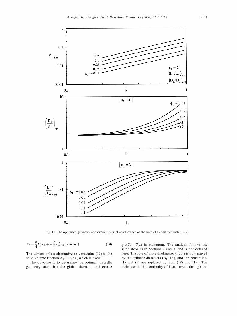
Fig. 11. The optimized geometry and overall thermal conductance of the umbrella construct with n1=2.
A. Bejan, M. Almogbel / Int. J. Heat Mass Transfer 43 (2000) 2101±2115 2111

umbrella hub of temperature T0. We report only theemerging dimensionless groups, and the optimizationresults. In place of parameter a of Eq. (5) we nowhave
b ��4hV 1=3
k
�1=2
�20�
The dimensionless global conductance de®nition (10) is
replaced by
~q1 �q1
kV 1=3�T1 ÿ T1� �21�
The optimized geometry for the case with two spokes
is summarized in Fig. 11. The geometry is representedby the aspect ratios �D1=D0�opt and �L1=L0�opt, whichare functions of b and f1. The ratio �D1=D0�opt
Fig. 12. The e�ect of the number of spokes n1 on the optimized geometry and overall thermal conductance of the umbrella con-
struct.
A. Bejan, M. Almogbel / Int. J. Heat Mass Transfer 43 (2000) 2101±21152112

approaches 1.82 as b drops below 0.1. The ratio�L1=L0�opt is nearly constant (00.4) when b is of theorder of 1. The twice maximized conductance behaves
as a power law in both b and f1; the data of the topframe of Fig. 11 are correlated within 12% by an ex-pression that is quite similar to Eq. (15),
~q1, mm � 0:77b1:47f0:611 �22�
The double optimization procedure (Fig. 11) was
repeated for larger n1 values. The results covering the
range 2R n1 R 15 are reported in Fig. 12a for constant
f1 and varying b, and in Fig. 12b for constant b and
varying f1. In both presentations the e�ect of n1 on
the twice-maximized conductance is weak. The ratio
�D1=D0�opt increases as n1 increases, i.e., the spokes
become relatively thinner when they are more numer-
Fig. 12 (continued)
A. Bejan, M. Almogbel / Int. J. Heat Mass Transfer 43 (2000) 2101±2115 2113
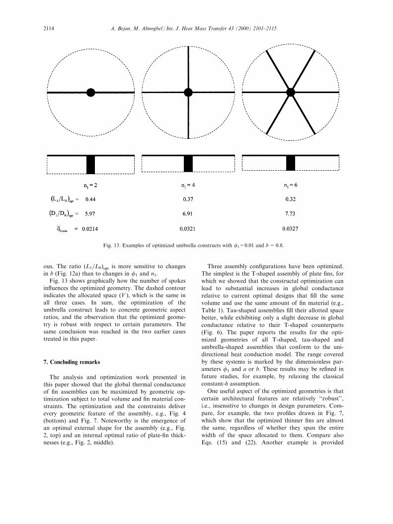
ous. The ratio �L1=L0�opt is more sensitive to changesin b (Fig. 12a) than to changes in f1 and n1.Fig. 13 shows graphically how the number of spokes
in¯uences the optimized geometry. The dashed contourindicates the allocated space (V ), which is the same inall three cases. In sum, the optimization of theumbrella construct leads to concrete geometric aspect
ratios, and the observation that the optimized geome-try is robust with respect to certain parameters. Thesame conclusion was reached in the two earlier cases
treated in this paper.
7. Concluding remarks
The analysis and optimization work presented in
this paper showed that the global thermal conductanceof ®n assemblies can be maximized by geometric op-timization subject to total volume and ®n material con-
straints. The optimization and the constraints deliverevery geometric feature of the assembly, e.g., Fig. 4(bottom) and Fig. 7. Noteworthy is the emergence of
an optimal external shape for the assembly (e.g., Fig.2, top) and an internal optimal ratio of plate-®n thick-nesses (e.g., Fig. 2, middle).
Three assembly con®gurations have been optimized.
The simplest is the T-shaped assembly of plate ®ns, for
which we showed that the constructal optimization can
lead to substantial increases in global conductance
relative to current optimal designs that ®ll the same
volume and use the same amount of ®n material (e.g.,
Table 1). Tau-shaped assemblies ®ll their allotted space
better, while exhibiting only a slight decrease in global
conductance relative to their T-shaped counterparts
(Fig. 6). The paper reports the results for the opti-
mized geometries of all T-shaped, tau-shaped and
umbrella-shaped assemblies that conform to the uni-
directional heat conduction model. The range covered
by these systems is marked by the dimensionless par-
ameters f1 and a or b. These results may be re®ned in
future studies, for example, by relaxing the classical
constant-h assumption.
One useful aspect of the optimized geometries is that
certain architectural features are relatively ``robust'',
i.e., insensitive to changes in design parameters. Com-
pare, for example, the two pro®les drawn in Fig. 7,
which show that the optimized thinner ®ns are almost
the same, regardless of whether they span the entire
width of the space allocated to them. Compare also
Eqs. (15) and (22). Another example is provided
Fig. 13. Examples of optimized umbrella constructs with f1=0.01 and b=0.8.
A. Bejan, M. Almogbel / Int. J. Heat Mass Transfer 43 (2000) 2101±21152114
by the optimized external and internal ratios��L1=L0�opt, �t1=t0�opt; Fig. 6), which do not vary signi®-
cantly with the lengths of the bent ends of the thinner®ns. The feature of robustness was also revealed by theoptimized architectures of other tree paths and duct
cross-sections produced by the constructal method [4].The robustness of some of the results, i.e., their
weak dependence on some of the constrained design
parameters, is also related to the idealizations thathave been adopted. An important idealization is theassumption that the heat transfer coe�cient is indepen-
dent of the free ¯ow area shape. Future studies mayaddress the e�ect of relaxing this assumption on T-assembly architecture. An example of how one mayproceed is given in Refs. [13,14], where the heat trans-
fer coe�cient was linked to (i.e., derived from) the op-timal spacing between adjacent parallel plates. Thechoice is based on the well known principle of optimiz-
ing internal spacings for both forced convection andnatural convection [15].
Acknowledgements
The work reported in this paper was supported by
the National Science Foundation and the General Or-ganization for Technical Education and VocationalTraining, Riyadh, Saudi Arabia.
References
[1] A. Bejan, Constructal-theory network of conducting
paths for cooling a heat generating volume,
International Journal of Heat and Mass Transfer 40
(1997) 799±816.
[2] N. Dan, A. Bejan, Constructal tree networks for the
time-dependent discharge of a ®nite-size volume to one
point, Journal of Applied Physics 84 (1998) 3042±3050.
[3] A. Bejan, M.R. Errera, Deterministic tree networks for
¯uid ¯ow: geometry for minimal ¯ow resistance between
a volume and one point, Fractals 5 (1997) 685±695.
[4] A. Bejan, Advanced Engineering Thermodynamics, 2nd
ed., Wiley, New York, 1997.
[5] A.D. Kraus, Developments in the analysis of ®nned
arrays, Donald Q. Kern Award Lecture, National Heat
Transfer Conference, Baltimore, MD, August 11, 1997,
International Journal of Transport Phenomena, 1 (1999)
141±164.
[6] A. Aziz, Optimum dimensions of extended surfaces
operating in a convective environment, Applied
Mechanics Reviews 45 (5) (1992) 155±173.
[7] W.R. Hamburgen, Optimal, ®nned heat sinks, WRL
Research Report 86/4, Digital, Western Research
Laboratory, Palo Alto, CA, 1986.
[8] D.J. Lee, W.W. Lin, Second-law analysis on a fractal-
like ®n under cross¯ow, AIChE Journal 41 (1995) 2314±
2317.
[9] W.W. Lin, D.J. Lee, Di�usion-convection process in a
branching ®n, Chemical Engineering Communications
158 (1997) 59±70.
[10] W.W. Lin, D.J. Lee, Second-law analysis on a pin-®n
array under cross-¯ow, International Journal of Heat
and Mass Transfer 40 (1997) 1937±1945.
[11] K.A. Gardner, E�ciency of extended surfaces,
Transactions ASME 67 (1945) 621±631.
[12] A. Bejan, Heat Transfer, Wiley, New York, 1993.
[13] A. Alebrahim, A. Bejan, Constructal trees of circular
®ns for conductive and convective heat transfer,
International Journal of Heat and Mass Transfer 42
(1999) 3585±3597.
[14] A. Bejan, N. Dan, Constructal trees of convective ®ns,
Journal of Heat Transfer 121 (1999) 675±682.
[15] A. Bejan, Convection Heat Transfer, 2nd ed., Wiley,
New York, 1995 (chapters 3 and 4).
A. Bejan, M. Almogbel / Int. J. Heat Mass Transfer 43 (2000) 2101±2115 2115


![Constructal Law & Second Law Conference 2019 CLC 2019 ... · [1] A. Bejan, “Constructal-theory network of conducting paths for cooling a heat generating volume,” Int. J. Heat](https://img.pdfslide.us/doc/110x75/60c5f72f8176ed7a690acebd/constructal-law-second-law-conference-2019-clc-2019-1-a-bejan-aoeconstructal-theory.jpg)


![[PPT]Constructal Theory - Faculty of Mechanical Engineering –mohsin/mmj1413/constructal.ppt · Web viewConstructal Theory Adrian Bejan, 1996 Constructal Law "For a finite-size system](https://img.pdfslide.us/doc/110x75/5b33c4597f8b9aa0238d287e/pptconstructal-theory-faculty-of-mechanical-engineering-mohsinmmj1413.jpg)