Embed Size (px)
Citation preview
Constructability and Challenges of the Slims and Duke Bridges Project
Mekdam Nima, Ph.D., P.Eng., Manager, Bridges, AECOM
Kian Mirza, Ph.D., P.Eng.
Asnee Pochanart, Ph.D., P.Eng.,
Amin Abdullah, P.Eng.
Paper prepared for presentation at the “Bridges – Successes: Let’s Build on Them
(B)” Session of the 2011 Annual Conference of the Transportation Association of Canada
Edmonton, Alberta
Constructability and Challenges of the Slims and Duke Bridges Project; Mekdam Nima et al. 1 _
Constructability and Challenges of the Slims and Duke Bridges Project By: Mekdam Nima, Ph.D., P.Eng., Kian Mirza, Ph.D., P.Eng., Asnee
Pochanart, Ph.D., P.Eng., and Amin Abdullah, P.Eng.
The Annual Conference of the Transportation Association of Canada, September 11‐14, 2011, Edmonton, Alberta
ABSTRACT
This paper discusses constructability implementation, lessons learned, and challenges encountered during the design and construction phases of projects. Slims River and Duke River Bridges replacement project on the Alaska Highway was selected as a case study.
The Slims River and Duke River are two major rivers in the Yukon. The replacement of the Slims River and the Duke River bridges on the Alaska Highway is part of the US-funded Shakwak project. The Shakwak project is part of the Shakwak agreement between the Canadian and United States Governments for the purpose of improving the Canadian highway sections that link the Alaskan panhandle to the Alaskan interior.
Since 1977, more than $1.8 billion has been spent rebuilding and maintaining the Alaska Highway through the international Shakwak Agreement. Slims River and Duke River Bridges Replacement Project is one of the major improvements undertaken under the Shakwak project.
Several challenges were encountered and mitigated during work on this project including:
Environmental Sensitive Zone Complex Hydraulics Active Seismic Zone Densification of Liquefiable Soil Traffic Management
Constructability implemented in many aspects of the project including:
Tight Schedule Extreme Weather Conditions Bridge Sliding Bridge Launching
In this paper we will analyze the factors that impacted project costs and summarize the specific approaches that were adopted for design and project delivery. We will also discuss the challenges that were encountered on this project and the lessons learned. The authors concluded that innovation during the design phase and constructability input at the preliminary and design phases of a project has a positive outcome on project budget and schedule during the construction phase. Ultimately, recommendations and strategies for future projects are presented herein.
INTRODUCTION
The Case Study
Slims and Duke are two major rivers in the Yukon. The Alaska Highway crosses the Slims River at Kilometre 1702 and the Duke River at Kilometre 1768. The two bridges were built at the two river crossing during the construction of Alaska Highway which was completed in 1942. It was decided to replace the bridges during the upgrading of the Alaska Highway as part of the US-funded Shakwak project. The new Duke River Bridge consists of 2 spans of 50 meters each, whereas Slims River Bridge consists of a single span of 80 meters. The
Constructability and Challenges of the Slims and Duke Bridges Project; Mekdam Nima et al. 2 _
replacement of these two bridges was considered one of the major improvements for the Alaska Highway.
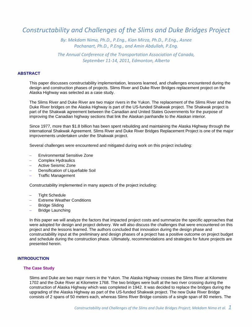
Figure 01 shows the location of the two bridges. The first author was the consultant’s project manager for this project. As part of this paper, he will be sharing the experience that he and the project team gained, the challenges, constructability implementation, and lessons learned from this project during the design and construction phases.
Project challenges discussed in this paper include; project location in an environmentally sensitive zone, complex hydraulics of rivers, bridges location in an active seismic zone, densification of liquefiable soil, and traffic management.
Figure 01 ‐ Yukon & Alaska Map
In response to the aforementioned and other challenges, constructability concepts were implemented in the project and will also be discussed in this paper. These concepts include; maintaining an aggressive construction schedule, designing for and constructing in extreme weather conditions, sliding of the bridges, and launching of the Slims Bridge.
Constructability and Challenges
The lack of constructability implementation in the construction industry has caused numerous problems, such as increased project costs and delays, reduced productivity of project personnel and equipment, and low quality work. One of the major constructability concepts is maintaining evaluation, documentation, and feedback regarding constructability issues throughout projects’ phases to be used on future projects as lessons learned [7,8].
Constructability review is an integral part of the success in design-build projects delivery model. In this model, constructability review is available to designers since they have access to the construction contractors. In this type of projects, collaboration between designers and builders results in a positive outcome on project budget and schedule during the construction phase [1]. In the traditional design-award-build, the selection of the project construction contractor is not decided at the design stage. Therefore, it is more challenging and difficult to implement constructability as designers are not in direct contact with construction contractors.
The design-award-build method of project delivery was used for the Slims River and Duke River project. As such, it was very difficult to smoothly implement constructability at an early stage of the project. Contacting contractors during the design phase of design-award-build projects could be considered a conflict of interest as project details could be revealed to some but not all contractors before the bidding process started.
Despite these challenges, some of the constructability concepts were implemented in this project. Working in the far north is challenging. The saying “Necessity is the Mother of All Inventions” could be applied to many aspects of the northern projects. Probably, that was one of the reasons behind spending more effort on these projects to study the ease of construction during the design and construction phases which led to the implementation of
Constructability and Challenges of the Slims and Duke Bridges Project; Mekdam Nima et al. 3 _
many constructability concepts.
Owners and designers recognized that construction at those far north sites is not traditional or easy. Consequently, many constructability concepts were discussed during the design phase of the project, such as overcoming extreme weather conditions, methods of construction, learning from previous similar project in the same environment, and documenting lessons learnt. This paper is part of the project documentation that hopefully will be used in future projects.
PROJECT DESCRIPTION AND BACKGROUND
The Alaska Highway
Slims and Duke are two major rivers in the Yukon. The Alaska Highway crosses the Slims River at Kilometre 1702 and the Duke River at Kilometre 1768. The two bridges were built at the two river crossing during the construction of Alaska Highway which was completed in 1942. It was decided to replace the bridges during the upgrading of the Alaska Highway as part of the US-funded Shakwak project. The new Duke River Bridge consists of 2 spans of 50 meters each, whereas the new Slims River Bridge consists of a single span of 80 meters. The replacement of these two bridges was considered one of the major improvements for the Alaska Highway.
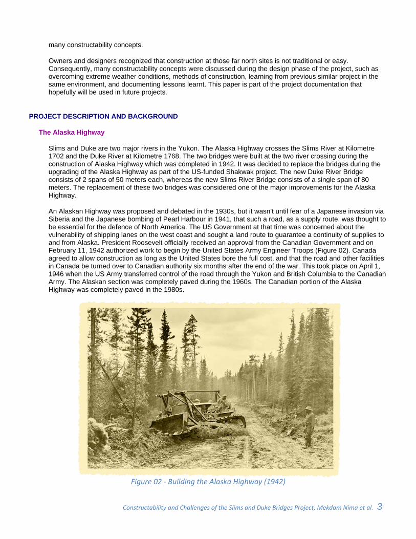
An Alaskan Highway was proposed and debated in the 1930s, but it wasn’t until fear of a Japanese invasion via Siberia and the Japanese bombing of Pearl Harbour in 1941, that such a road, as a supply route, was thought to be essential for the defence of North America. The US Government at that time was concerned about the vulnerability of shipping lanes on the west coast and sought a land route to guarantee a continuity of supplies to and from Alaska. President Roosevelt officially received an approval from the Canadian Government and on February 11, 1942 authorized work to begin by the United States Army Engineer Troops (Figure 02). Canada agreed to allow construction as long as the United States bore the full cost, and that the road and other facilities in Canada be turned over to Canadian authority six months after the end of the war. This took place on April 1, 1946 when the US Army transferred control of the road through the Yukon and British Columbia to the Canadian Army. The Alaskan section was completely paved during the 1960s. The Canadian portion of the Alaska Highway was completely paved in the 1980s.
Figure 02 ‐ Building the Alaska Highway (1942)
Constructability and Challenges of the Slims and Duke Bridges Project; Mekdam Nima et al. 4 _
Shakwak Agreement, Slims River Bridge, and Duke River Bridge
In 1976, the United States and Canada reached a highway construction funding agreement for the Shakwak Project. The agreement, covering the Canadian portions of the Haines Highway and Alaska Highway, addressed the long-standing requests from Alaskans for improvement of the roads connecting the panhandle with the rest of the state of Alaska. Since 1977, more than $1.8 billion has been spent rebuilding and maintaining the Alaska Highway through the international Shakwak Agreement [11]. Slims River and Duke River Bridges Replacement Project is part of the Shakwak Agreement.
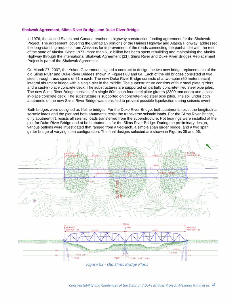
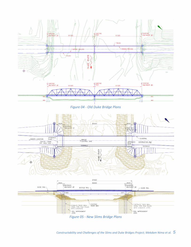
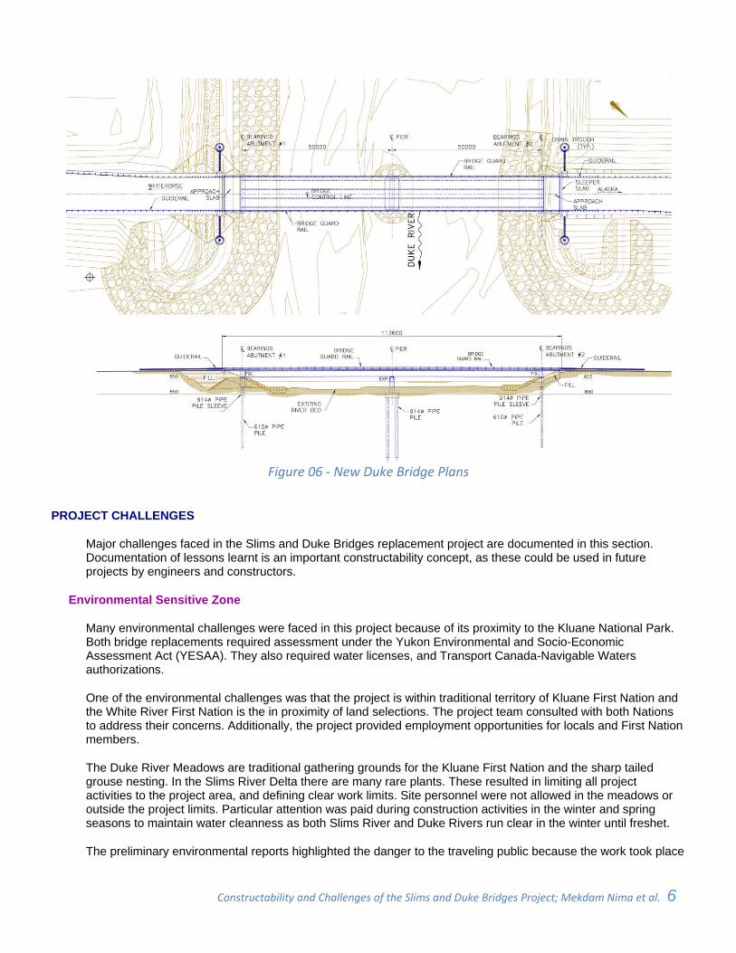
On March 27, 2007, the Yukon Government signed a contract to design the two new bridge replacements of the old Slims River and Duke River Bridges shown in Figures 03 and 04. Each of the old bridges consisted of two steel through truss spans of 61m each. The new Duke River Bridge consists of a two-span (50 meters each) integral abutment bridge with a single pier in the middle. The superstructure consists of four steel plate girders and a cast-in-place concrete deck. The substructures are supported on partially concrete-filled steel pipe piles. The new Slims River Bridge consists of a single 80m span four steel plate girders (3300 mm deep) and a cast-in-place concrete deck. The substructure is supported on concrete-filled steel pipe piles. The soil under both abutments of the new Slims River Bridge was densified to prevent possible liquefaction during seismic event.
Both bridges were designed as lifeline bridges. For the Duke River Bridge, both abutments resist the longitudinal seismic loads and the pier and both abutments resist the transverse seismic loads. For the Slims River Bridge, only abutment #1 resists all seismic loads transferred from the superstructure. Pot bearings were installed at the pier for Duke River Bridge and at both abutments for the Slims River Bridge. During the preliminary design, various options were investigated that ranged from a tied-arch, a simple span girder bridge, and a two span girder bridge of varying span configuration. The final designs selected are shown in Figures 05 and 06.
Figure 03 ‐ Old Slims Bridge Plans
Constructability and Challenges of the Slims and Duke Bridges Project; Mekdam Nima et al. 5 _
Figure 04 ‐ Old Duke Bridge Plans
Figure 05 ‐ New Slims Bridge Plans
Constructability and Challenges of the Slims and Duke Bridges Project; Mekdam Nima et al. 6 _
Figure 06 ‐ New Duke Bridge Plans
PROJECT CHALLENGES
Major challenges faced in the Slims and Duke Bridges replacement project are documented in this section. Documentation of lessons learnt is an important constructability concept, as these could be used in future projects by engineers and constructors.
Environmental Sensitive Zone
Many environmental challenges were faced in this project because of its proximity to the Kluane National Park. Both bridge replacements required assessment under the Yukon Environmental and Socio-Economic Assessment Act (YESAA). They also required water licenses, and Transport Canada-Navigable Waters authorizations.
One of the environmental challenges was that the project is within traditional territory of Kluane First Nation and the White River First Nation is the in proximity of land selections. The project team consulted with both Nations to address their concerns. Additionally, the project provided employment opportunities for locals and First Nation members.
The Duke River Meadows are traditional gathering grounds for the Kluane First Nation and the sharp tailed grouse nesting. In the Slims River Delta there are many rare plants. These resulted in limiting all project activities to the project area, and defining clear work limits. Site personnel were not allowed in the meadows or outside the project limits. Particular attention was paid during construction activities in the winter and spring seasons to maintain water cleanness as both Slims River and Duke Rivers run clear in the winter until freshet.
The preliminary environmental reports highlighted the danger to the traveling public because the work took place
Constructability and Challenges of the Slims and Duke Bridges Project; Mekdam Nima et al. 7 _
directly adjacent to the road. This issue was considered in the traffic management plans of the project.
During construction, many mitigation procedures were implemented to minimize or eliminate soil and water contamination or spills during equipment operation and maintenance. Those include disposing of waste materials appropriately, conducting equipment repair and maintenance activities away from waterways, not allowing any fuelling within 30m of open water, and not permitting any leaky equipment near stream activities.
Complex Hydraulics
The hydraulic studies were done with the structural and geotechnical factors in mind. Changing the water course configuration could lead to global stability issues. In a previous project (North Saskatchewan River Bridge Project, Edmonton, Alberta), additional weight of the large approach fills was found to cause a slide beneath the approaches. To solve that problem tangent pile walls were used as prevention [4]. Whereas, similar concerns could be raised with major soil cuts, if weak soil is exposed during the cut. In the Saint Albert Bridge Project, (Edmonton, Alberta) exposing weak soil caused geotechnical and soil stability issues. This was dealt with by using secant pile walls [1]. In the Slims and Duke Bridges Replacement Project, these problems were not faced. Only riprap was used to ensure stability of the berms and protection from scour erosion.
During the hydrotechnical studies, eight bridge models for the Duke River Bridge and nine models for the Slims River Bridge were studied to assess the channel hydraulics at each bridge site. The models were simulated to determine the design water surface elevation, velocity, and potential scour. This was done to find the best and most economical opening configuration option for each bridge, and minimize effects on the water flow and scour. Bridge alternatives studied included single span and multiple span options.
Both the Slims River and Duke River channels at the bridge site are in wide floodplains. Hydrotechnical studies of both rivers were conducted in 2007. The flood flow estimation is based on 22 years of observed data for the Duke River. However, there were no long term hydrometric data for the Slims River. As a result, combinations of longer periods of hydrometric data from neighbouring stations were used to enhance the previous flow estimations for the Slims River.
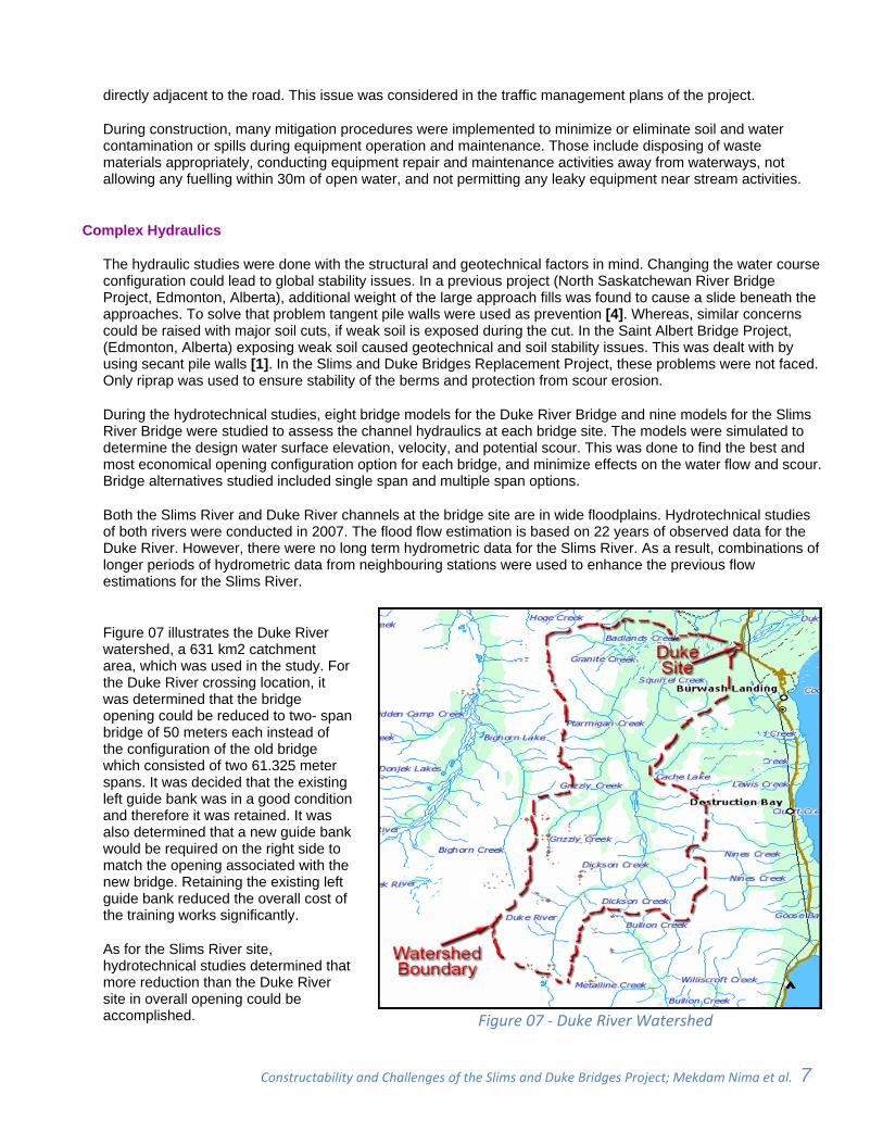
Figure 07 illustrates the Duke River watershed, a 631 km2 catchment area, which was used in the study. For the Duke River crossing location, it was determined that the bridge opening could be reduced to two- span bridge of 50 meters each instead of the configuration of the old bridge which consisted of two 61.325 meter spans. It was decided that the existing left guide bank was in a good condition and therefore it was retained. It was also determined that a new guide bank would be required on the right side to match the opening associated with the new bridge. Retaining the existing left guide bank reduced the overall cost of the training works significantly.
As for the Slims River site, hydrotechnical studies determined that more reduction than the Duke River site in overall opening could be accomplished.
Figure 07 ‐ Duke River Watershed
Constructability and Challenges of the Slims and Duke Bridges Project; Mekdam Nima et al. 8 _
A single span of 80 meters could replace the two spans of the old bridge totalling 122.65 meters. At the Slims River site, the proposed training works included guide banks upstream and downstream of the bridge. The old guide banks were protected by rip rap with rocks of about 200 mm diameter each. The old guide banks did not provide sufficient scour protection based on the calculated river velocities and potential scour. Therefore, the guide banks were reconstructed and tied into the proposed new bridge opening. The guide banks were extended approximately 150 m upstream and 50 m downstream of the crossing. New plans of Slims River Bridge and Duke River Bridge in Figures 05 and 06 respectively show these details.
Active Seismic Zone
Another challenge was the seismic design of these two bridges. Opening the Alaska Highway after an earthquake event is a crucial matter for both Governments of Canada and the US. Both Slims River and Duke River bridges are in a high seismic activity zone. Also there is a high potential of liquefaction during a seismic event at the Slims River Bridge site, because of the soil condition and high water table. History recorded the 1964 Alaska earthquake as disastrous earthquake that took place on Good Friday, March 27, 1964. It caused about 131 deaths. Lasting nearly four minutes, it was the most powerful recorded earthquake in the US and the North American history. It had a magnitude of 9. 2 on the Richter scale, making it the second largest earthquake in recorded history at that time.
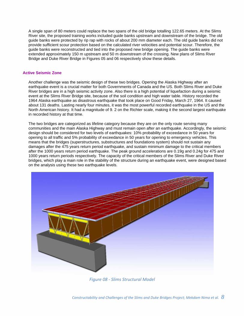
The two bridges are categorized as lifeline category because they are on the only route serving many communities and the main Alaska Highway and must remain open after an earthquake. Accordingly, the seismic design should be considered for two levels of earthquakes: 10% probability of exceedance in 50 years for opening to all traffic and 5% probability of exceedance in 50 years for opening to emergency vehicles. This means that the bridges (superstructures, substructures and foundations system) should not sustain any damages after the 475 years return period earthquake, and sustain minimum damage to the critical members after the 1000 years return period earthquake. The peak ground accelerations are 0.19g and 0.24g for 475 and 1000 years return periods respectively. The capacity of the critical members of the Slims River and Duke River bridges, which play a main role in the stability of the structure during an earthquake event, were designed based on the analysis using these two earthquake levels.
Figure 08 ‐ Slims Structural Model
Constructability and Challenges of the Slims and Duke Bridges Project; Mekdam Nima et al. 9 _
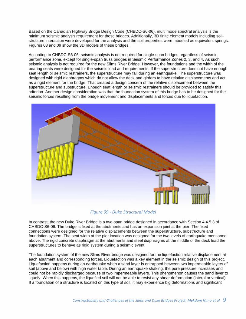
Based on the Canadian Highway Bridge Design Code (CHBDC-S6-06), multi mode spectral analysis is the minimum seismic analysis requirement for these bridges. Additionally, 3D finite element models including soil-structure interaction were developed for the analysis and the soil properties were modeled as equivalent springs. Figures 08 and 09 show the 3D models of these bridges.
According to CHBDC-S6-06; seismic analysis is not required for single-span bridges regardless of seismic performance zone, except for single-span truss bridges in Seismic Performance Zones 2, 3, and 4. As such, seismic analysis is not required for the new Slims River Bridge. However, the foundations and the width of the bearing seats were designed for the seismic load and requirements. If the superstructure does not have enough seat length or seismic restrainers, the superstructure may fall during an earthquake. The superstructure was designed with rigid diaphragms which do not allow the deck and girders to have relative displacements and act as a rigid element for the bridge. That created a design concern of the relative displacement between the superstructure and substructure. Enough seat length or seismic restrainers should be provided to satisfy this criterion. Another design consideration was that the foundation system of this bridge has to be designed for the seismic forces resulting from the bridge movement and displacements and forces due to liquefaction.
Figure 09 ‐ Duke Structural Model
In contrast, the new Duke River Bridge is a two-span bridge designed in accordance with Section 4.4.5.3 of CHBDC-S6-06. The bridge is fixed at the abutments and has an expansion joint at the pier. The fixed connections were designed for the relative displacements between the superstructure, substructure and foundation system. The seat width at the pier location was designed for the two levels of earthquake mentioned above. The rigid concrete diaphragm at the abutments and steel diaphragms at the middle of the deck lead the superstructures to behave as rigid system during a seismic event.
The foundation system of the new Slims River bridge was designed for the liquefaction relative displacement at each abutment and corresponding forces. Liquefaction was a key element in the seismic design of this project. Liquefaction happens during an earthquake when a sand layer is entrapped between two impermeable layers of soil (above and below) with high water table. During an earthquake shaking, the pore pressure increases and could not be rapidly discharged because of two impermeable layers. This phenomenon causes the sand layer to liquefy. When this happens, the liquefied soil will not be able to resist any shear deformation (lateral or vertical). If a foundation of a structure is located on this type of soil, it may experience big deformations and significant
Constructability and Challenges of the Slims and Duke Bridges Project; Mekdam Nima et al. 10 _
damages that cause instability of the structure.
Liquefaction for different levels of earthquakes, and the relative displacement and the acting forces on the foundation system should be studied. If the forces and displacements are so enormous that the foundation cannot reasonably be design for them, mitigation procedures should be considered for the specific site.
Densification procedure (vibro-replacement method) was used for the Slims River Bridge, as the level of forces and settlements were found to be high. This topic will be discussed in details along with an introduction to the other approaches in the next section.
Potential of liquefaction was studied for different return period earthquakes to investigate the occurrence of this phenomenon at each level, and its effects on the p-y curves. This is described in the following section in details.
Densification of Liquefiable Soil
Alaska’s powerful earthquake of March 27, 1964 produced soil liquefaction in the region. On June 16, 1964 another powerful earthquake of a magnitude of 7.5 hit Niigata, Japan. Remarkable ground failures occurred causing soil bearing capacity failures and causing building to tilt severely. Despite this tilting, the buildings themselves suffered remarkably little structural damage. The Niigata earthquake and the Alaska earthquake of 1964, brought liquefaction phenomena and their devastating effects to the attention of engineers and seismologists [10].
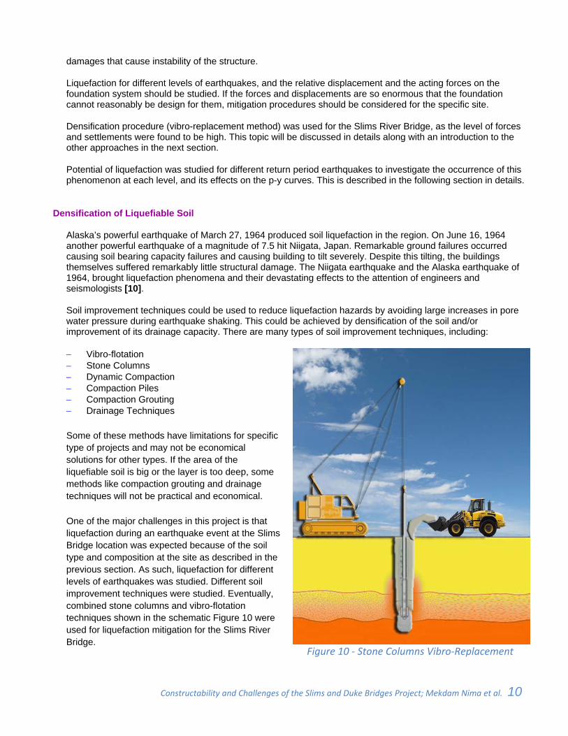
Soil improvement techniques could be used to reduce liquefaction hazards by avoiding large increases in pore water pressure during earthquake shaking. This could be achieved by densification of the soil and/or improvement of its drainage capacity. There are many types of soil improvement techniques, including:
Vibro-flotation Stone Columns Dynamic Compaction Compaction Piles Compaction Grouting Drainage Techniques
Some of these methods have limitations for specific type of projects and may not be economical solutions for other types. If the area of the liquefiable soil is big or the layer is too deep, some methods like compaction grouting and drainage techniques will not be practical and economical.
One of the major challenges in this project is that liquefaction during an earthquake event at the Slims Bridge location was expected because of the soil type and composition at the site as described in the previous section. As such, liquefaction for different levels of earthquakes was studied. Different soil improvement techniques were studied. Eventually, combined stone columns and vibro-flotation techniques shown in the schematic Figure 10 were used for liquefaction mitigation for the Slims River Bridge.
Figure 10 ‐ Stone Columns Vibro‐Replacement
Constructability and Challenges of the Slims and Duke Bridges Project; Mekdam Nima et al. 11 _
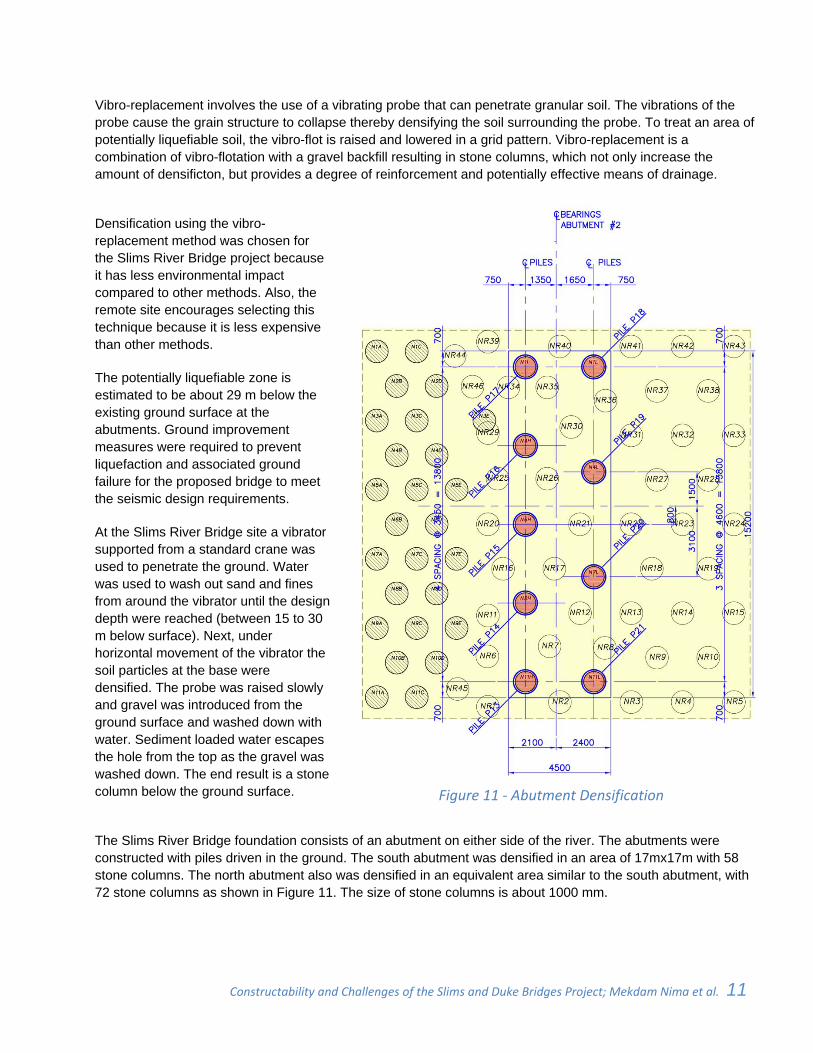
Vibro-replacement involves the use of a vibrating probe that can penetrate granular soil. The vibrations of the probe cause the grain structure to collapse thereby densifying the soil surrounding the probe. To treat an area of potentially liquefiable soil, the vibro-flot is raised and lowered in a grid pattern. Vibro-replacement is a combination of vibro-flotation with a gravel backfill resulting in stone columns, which not only increase the amount of densificton, but provides a degree of reinforcement and potentially effective means of drainage.
Densification using the vibro-replacement method was chosen for the Slims River Bridge project because it has less environmental impact compared to other methods. Also, the remote site encourages selecting this technique because it is less expensive than other methods.
The potentially liquefiable zone is estimated to be about 29 m below the existing ground surface at the abutments. Ground improvement measures were required to prevent liquefaction and associated ground failure for the proposed bridge to meet the seismic design requirements.
At the Slims River Bridge site a vibrator supported from a standard crane was used to penetrate the ground. Water was used to wash out sand and fines from around the vibrator until the design depth were reached (between 15 to 30 m below surface). Next, under horizontal movement of the vibrator the soil particles at the base were densified. The probe was raised slowly and gravel was introduced from the ground surface and washed down with water. Sediment loaded water escapes the hole from the top as the gravel was washed down. The end result is a stone column below the ground surface. Figure 11 ‐ Abutment Densification
The Slims River Bridge foundation consists of an abutment on either side of the river. The abutments were constructed with piles driven in the ground. The south abutment was densified in an area of 17mx17m with 58 stone columns. The north abutment also was densified in an equivalent area similar to the south abutment, with 72 stone columns as shown in Figure 11. The size of stone columns is about 1000 mm.
Constructability and Challenges of the Slims and Duke Bridges Project; Mekdam Nima et al. 12 _
Traffic Management
Nowadays, there are greater pressures and incentives for engineers and contractors to construct new bridges with minimal disruption to existing transport systems and the environment. Work zone planning and traffic management have become increasingly challenging because of increased travel demand and an aging roadway network infrastructure requiring more frequent maintenance and major rehabilitations.
When works take place on provincial or territorial highways there may be disruptions or delays to existing traffic that cause inconvenience to highway users. There is a need to ensure the continued effective function of the highway during any such work, and careful consideration of acceptable delays.
Traffic management was a key challenge and an essential part of the Slims River and Duke River Bridges replacement project. Maintaining traffic during construction was the most important facet. It was crucial to ensured safe and efficient traffic flow while constructing the bridges.
Bridge replacements impede existing traffic patterns. To maintain traffic through the bridge site, few alternatives are available which include:
1. Detour on other routes, 2. Stage construction, 3. Construction of shooflies.
For the Slims and Duke project, the first option was eliminated, because there is no other practical route available to serve the surrounding communities in Canada and no other land connection between Alaska and the rest of the United States in the south.
The second option was also eliminated for many reasons. Firstly, over the years, truck loads increased and the seismic requirements became more stringent in the new codes versus old codes. Thus, the existing bridge substructures were not sufficient enough to carry new superstructures. Secondly, Slims River and Duke River Bridges are through truss structures which limit the widening of the bridges. Thirdly, there is no way to construct the new bridges in stages at the same highway alignment.
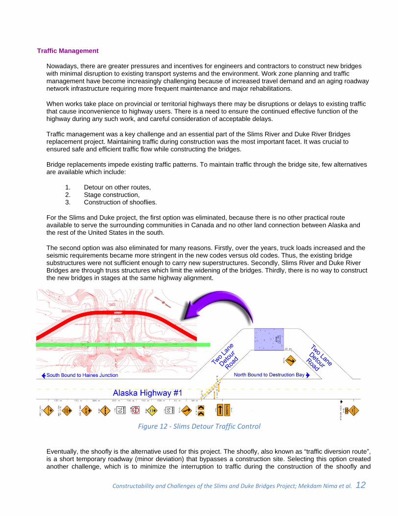
Figure 12 ‐ Slims Detour Traffic Control
Eventually, the shoofly is the alternative used for this project. The shoofly, also known as “traffic diversion route”, is a short temporary roadway (minor deviation) that bypasses a construction site. Selecting this option created another challenge, which is to minimize the interruption to traffic during the construction of the shoofly and
Constructability and Challenges of the Slims and Duke Bridges Project; Mekdam Nima et al. 13 _
diverting traffic. It was also important to keep the road closure to an absolute minimum. The concept and final design of this detour is shown in Figure 12.
Thorough studies at the early stages of the project recommended using one of the truss spans of each bridge as a temporary bridge on the shoofly. This led the project team to start thinking of sliding the bridges, which is explained in another section in this paper.
CONSTRUCTABILITY
Tight Schedule
A major constructability consideration is the right balance between schedule, budget and quality [6]. The duration of construction projects has been assuming greater importance in the construction industry. Owners and clients are no longer content merely with minimal costs of their projects. In many instances, it is more cost-effective to complete a project within the shortest possible time in order to minimize the economical impacts of traffic delays, missing construction seasons, interest rates, inflation, and uncertainty of price changes [5]. For the Slims River and Duke River Bridges, scheduling are of the essence, not only for the above-mentioned reason but also because of the short construction season and unique remote location of the bridges.
The Alaska Highway, also known as the Alcan (Alaska-Canadian) Highway, is the only land route between the State of Alaska and other US states and connecting many Yukon communities. As an integral part of the highway, Slims River and Duke River Bridges are considered lifeline bridges under Clause 4. 4. 2 (Importance categories) of the CHBDC-S6-06. According to this code, lifeline bridges are generally those that carry or cross over routes that need to remain open to all traffic after the occurrence of the design earthquake. A design earthquake is an event with a 10% probability of exceedance in 50 years (equivalent to a 15% probability of exceedance in 75 years and a return period of 475 years). Lifeline bridges also need to be usable by emergency vehicles and for security and defence purposes immediately after a major earthquake, e.g., a 1000-year return period event (7.5% probability of exceedance in 75 years). This requirement is another reason for the importance of schedule and minimum disturbance to the Alaska Highway.
The remoteness of the Slims River and Duke River Bridges is another factor that added to the importance of the project schedule. In many remote sites, the cost to mobilize personnel, materials, and equipment is very high; and the on-going costs for re-supply, crew changes, potential lost time in obtaining equipment repair parts, etc. , are also very high [3]. Accordingly, the more accurate planning and scheduling, the less risk associated with the project.
To complicate the project schedule and make it even more challenging; the two bridges are located in extreme weather climate. The site is susceptible to unpredictable high wind with snow or dust. Because of the limited construction season and the extreme weather conditions slip in the schedule’s activities and milestones must be avoided. Delays in the project schedule could shift the project completion by an additional construction season, the result of which could increase the construction costs and inconvenience to the public significantly.
The project design and construction phases were maintained as originally planned and scheduled, as a result of implementing many constructability measures, including: work zone planning and traffic management, planning ahead for sideway sliding of existing bridges and using construction methods such as bridge launching, as described in the next sections.
Extreme Weather Conditions
The extreme unpredicted weather conditions at the project sites called for considering constructability and imposing many design constrains and additional requirements. During the design phase of any project, designers play a major role in the success of the project by planning in advance. The constructability concept of “early project planning should actively involve individuals with current construction knowledge and experience” was applied here. Extreme weather conditions should be one of the considerations for designers during the
Constructability and Challenges of the Slims and Duke Bridges Project; Mekdam Nima et al. 14 _
design phase [9]. In the Slims River and Duke River Bridges Project, adverse weather conditions at the site were considered in the conceptual design phase by choosing the construction method. Adverse weather conditions also have significant influence on the design as will be described later in this section.
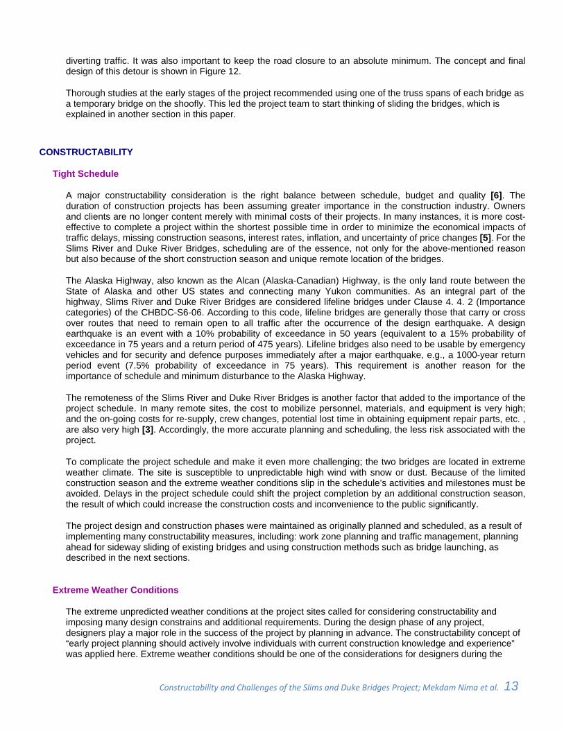
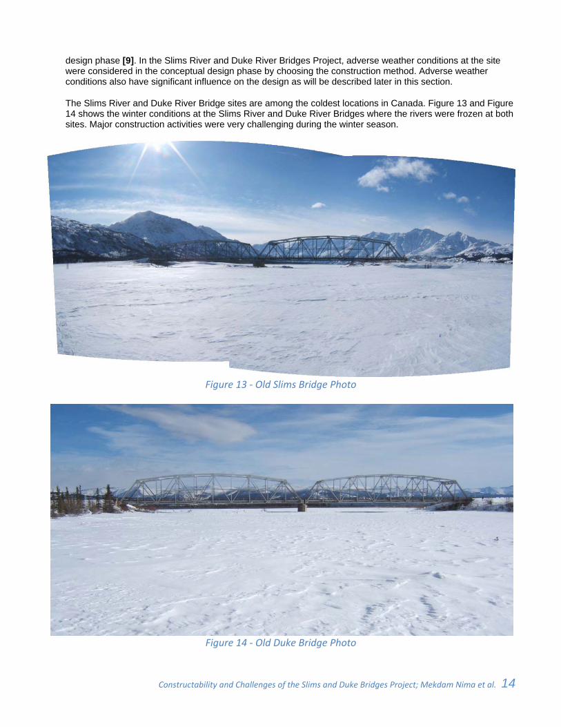
The Slims River and Duke River Bridge sites are among the coldest locations in Canada. Figure 13 and Figure 14 shows the winter conditions at the Slims River and Duke River Bridges where the rivers were frozen at both sites. Major construction activities were very challenging during the winter season.
Figure 13 ‐ Old Slims Bridge Photo
Figure 14 ‐ Old Duke Bridge Photo
Constructability and Challenges of the Slims and Duke Bridges Project; Mekdam Nima et al. 15 _
Cold temperatures often bring snow, cause icing, and other adverse conditions that warrant special equipment that include the normal construction personal protective equipment in addition to clothing such as gloves, facemasks, and ice/snow traction devices attached to heavy boots. Unpredictable high wind with snow or dust could shut down the work at any time of the day. Other requirements include enclosures for trailers, heaters, winter fuels mixed with anti-gelling additives, hot water pressure washers and anti-freezing biodegradable washer fluid for washing, concrete blankets and plastic tarps for concrete placing, and enclosures for grouting activates.
Executing concrete work at remote locations under extreme cold weather was challenging. When the temperature dipped below 5C, the cold weather requirements per the Canadian Standards Association Code (CSA A23.1) had to be followed. Aggregates had to be pre-heated prior to concrete mixing. Reinforcing bars had to be kept warm within the required temperature range prior to the concrete placement. The concrete discharge temperature had to be between 10C and 18C. Under specific conditions the concrete was cured under supplemental heat. Construction crews used extra heaters and heavy insulated concrete blankets to ensure that the structures cured even in very cold temperatures. For the first three days, the concrete temperature had to be kept between 15C and 27C. After that it was kept at above 10C for additional 4 days and 10 days for substructure and superstructure respectively.
With the minimum daily mean temperature at the Slims River and Duke River Bridge sites of -47C and maximum daily mean temperature of 22C, i.e. temperature range of 69C, the corresponding large bridge superstructure movement had to be taken into account in the design of bearings and expansion joints. Pot bearings and conventional strip seal expansion joint with sliding cover plates were used for the 80 m single span Slims River Bridge. At the expansion ends of the bridge, allowance for a large bridge superstructure movement range had to be accounted for in the sliding plate design for the pot bearings. While for the Duke River Bridge, the two ends of the double span (50 m each) were supported on integral abutments. The large bridge superstructure movement had to be accounted for by encircling each pipe pile with a larger diameter pipe sleeve. Conventional expansion joints similar to those used at the Slims River Bridge were used at the end of the two approach slabs of the Duke River Bridge.
For the two-span Duke River Bridge, both the effects of the temperature gradient and differential support settlement had to be accounted for in the cracks control of the deck at the central pier under the Service Limit State Design.
Bridge Sliding
As mentioned earlier, one of the challenges faced in this project was to keep the Alaska Highway open at all times as this is a major travel route for Canadians and the Americans. For Slims River and Duke River there was no option available for the diversion of traffic and the temporary bridge needed to be installed as quickly as possible with minimum disruption to traffic. Studies during the conceptual and final design phases determined that to slide bridges on a shoofly was the most efficient method. That solution involved moving one of the two spans from each of the old bridges to be used as part of the detour.
Sliding the bridges was considered one of the most constructable and innovative solutions used in the Slims River and Duke River Bridges replacement project. However, there was a substantial number of temporary items that were erected as a part of this process that needed to be removed after the slide operation was completed.
As discussed in the previous Section, a shoofly was used for this project. At both sites, the old bridges were slid transversely and used as detour bridges in locations that created space to build the new structures in a single stage. Temporary foundations were constructed for the detour bridges on one side of the old bridge.
The existing bridges truss spans were relocated about 75 meters from the sides of the old bridges locations, turning them into detour bridges that stayed in place during the construction period. Before the spans were moved, new temporary foundations and abutments were built beside the old bridges. Temporary steels rails supported on concrete lock blocks, and jacks were used to move the spans. Those were also being built at the temporary detour bridge location. Once the new bridge was completed, the old span and temporary supports
Constructability and Challenges of the Slims and Duke Bridges Project; Mekdam Nima et al. 16 _
were removed. Bridge sliding requires substantial planning, co-ordination and extensive temporary work. Extra space needs to be available to allow for site preparation, a work fabrication area and for any special equipment.
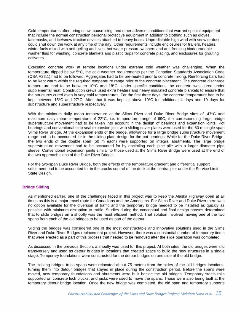
The Slims River and Duke River Bridges old spans were jacked up; positioned on sliding rails, slid sideways, then lowered down on new temporary foundations. The roadway detours for both bridges were prepared before the jacking. Final adjustments and fill on the temporary bridge approaches have been done before opening the detour to traffic.
Figure 15 shows the preparation process few hours before starting the sliding of the Duke River Bridge. The photo shows that the railings were installed and the workers were preparing to jack up the bridge from its old abutment to position it on the sliding rails.
Figure 15 ‐ Preparation for Moving Duke Bridge
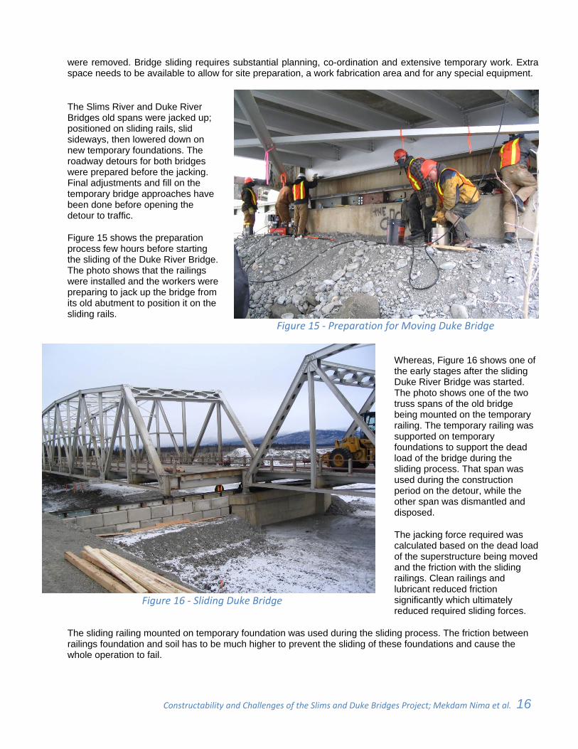
Figure 16 ‐ Sliding Duke Bridge
Whereas, Figure 16 shows one of the early stages after the sliding Duke River Bridge was started. The photo shows one of the two truss spans of the old bridge being mounted on the temporary railing. The temporary railing was supported on temporary foundations to support the dead load of the bridge during the sliding process. That span was used during the construction period on the detour, while the other span was dismantled and disposed.
The jacking force required was calculated based on the dead load of the superstructure being moved and the friction with the sliding railings. Clean railings and lubricant reduced friction significantly which ultimately reduced required sliding forces.
The sliding railing mounted on temporary foundation was used during the sliding process. The friction between railings foundation and soil has to be much higher to prevent the sliding of these foundations and cause the whole operation to fail.
Constructability and Challenges of the Slims and Duke Bridges Project; Mekdam Nima et al. 17 _
Bridge Launching
Recently, bridge designers and constructors started to experiment more and more with bridge launching as a construction method. Dr. Nima worked on several projects that utilized this method. Lessons learnt from previous projects were utilized in this projects as suggested by one of the constructability concept.
One scenario in bridge launching project is when bridge designers are aware of methods of construction and aware of constructability concepts, then they could utilize these lessons during the design phase, particularly for bridge launching technique. A second scenario is when launching is not considered during the design phase, and for specific site requirements, the contractor finds that this method is the most efficient.
Using bridge launching method might require increasing some of the girders section. In the second scenario, the contractor will be phased with redesign or rechecking the design in hand to beef up some girder sections. The reason is that there are additional stresses in the girder due to the cantilever action of girders during launching that might exceed the stresses created by live, dead and other loads in the girders at their final position.
For Slims River Bridge, the superstructure consists of cast-in-situ concrete slab on four lines of steel plate girders. Few girder erection options were studied during the design phase of this project. The incremental launching was determined to be the most suitable method for girder installation at this location during the design phase and was considered in the design.
The bridge lunching method was used for the Slims River Bridge because of many reasons including the remote location and environmental issues. Using crane on barges was found to be unfeasible. Considering unpredictable high wind with snow or dust, use of a heavy crane on the banks was not desirable. Due to the combination of these factors, launching was determined to be the best option for construction.
Launching was investigated from both approach embankments. It was decided during the design that the girders could be launched from either sides of the bridge. A 20m long launching nose was used, with Hillman rollers installed at all supports. The most suitable locations for temporary supports were considered to reduce reactions at supports and reduce bending moments and shear forces in the girders during launching. The findings and conclusions of the analysis were as follows:
The deflections at the tip of the girders, which were in the order of 350mm could be easily accommodated by flap jacks or vertical jacks attached to the girder ends or to the side of the existing pier.
The Hilman Rollers provided very little resistance during launching; therefore the launching forces were insignificant and did not detrimentally affect the existing bridge abutments and pier.
After the analysis and based on the results, the following procedure was considered for lunching method:
Laying out a launching area, to serve as work area where the bridge was assembled. This area required excavation.
Providing vertical rollers (side guides) and horizontal rollers at several key locations. Horizontal rollers were equipped with hydraulic jacks to provide steering and alignment control.
Erecting all of the steel structure including all four girder lines, diaphragms and upper and lower lateral bracing in the construction area.
Attaching a tail section to the trailing end of the girders, and a jacking device to the leading end of the girders to lift the deflected girders on top of the landing pier roller or landing abutment roller.
Pulling and pushing the four connected girders forward from one abutment to the other. The existing pier was used as a temporary support to reduce the cantilever forces during the launching. The girders were pulled from the front and pushed from the back into place on top of Hillman rollers. With very little change to the girder designs for dead and live loads; all four girders were launched at the same time.
Braking devices were provided to control the movement of the girders during launching. Bracing of both flanges of all four girders were also provided during launching.
Constructability and Challenges of the Slims and Duke Bridges Project; Mekdam Nima et al. 18 _
The first author has been involved in the design and construction of several bridges, where launching was used during construction. He concluded in a similar study on another remote bridge location (Great Bear River Bridge in Northwest Territories, Canada) that bridge launching is most cost effective when site conditions allow [2,3]. It could be used efficiently in projects with similar environments and circumstances to expedite project schedule and optimize budget. Same conclusion was reached while studying the Slims River Bridge erection methods.
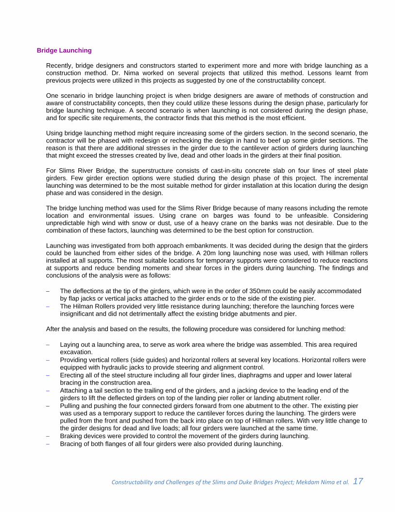
Figure 17 ‐ Bridge Launching Procedures
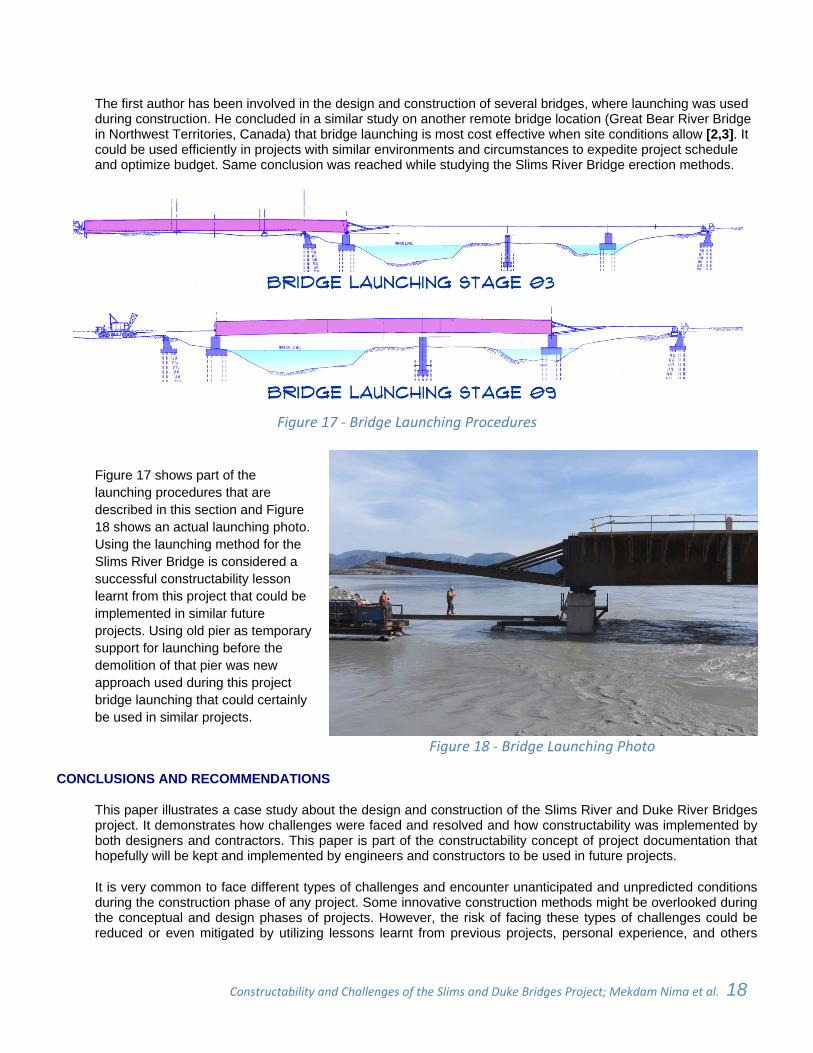
Figure 17 shows part of the launching procedures that are described in this section and Figure 18 shows an actual launching photo. Using the launching method for the Slims River Bridge is considered a successful constructability lesson learnt from this project that could be implemented in similar future projects. Using old pier as temporary support for launching before the demolition of that pier was new approach used during this project bridge launching that could certainly be used in similar projects.
Figure 18 ‐ Bridge Launching Photo
CONCLUSIONS AND RECOMMENDATIONS
This paper illustrates a case study about the design and construction of the Slims River and Duke River Bridges project. It demonstrates how challenges were faced and resolved and how constructability was implemented by both designers and contractors. This paper is part of the constructability concept of project documentation that hopefully will be kept and implemented by engineers and constructors to be used in future projects.
It is very common to face different types of challenges and encounter unanticipated and unpredicted conditions during the construction phase of any project. Some innovative construction methods might be overlooked during the conceptual and design phases of projects. However, the risk of facing these types of challenges could be reduced or even mitigated by utilizing lessons learnt from previous projects, personal experience, and others
Constructability and Challenges of the Slims and Duke Bridges Project; Mekdam Nima et al. 19 _
experiences during conceptual design and construction phases.
During the design phase, and after engineers found out about the liquefaction phenomena, designers started to pay particular attention to the densification of liquefiable soil in active seismic zones. The paper discussed this phenomenon, its possible and available solutions, and how designers mitigated this problem in the Slims River Bridge Project. A specific attention must be paid by designers to the liquefaction in active seismic zones.
During the construction phase, traffic management was found to be of a great influence on the success of bridge projects, especially when limited detour or diversion options are available. It is recommended to have specialized engineers studying the work zone and traffic management in the early phases of similar bridge and highway projects.
Extreme weather conditions in the far north impose many challenges for designers and contractors. It is recommended that designers and contractors pay specific attention and consider measurements to mitigate these types of challenges. Available codes also provide guidance to designers and contractors as was discussed in details in the paper.
Many constructability lessons learned that could benefit similar bridge projects are documented in this paper. Two interesting construction techniques were used in the Slims River and Duke River Bridges project; namely: sliding and launching bridges. It was concluded that using these methods during construction is very efficient for both schedule and budget. It is recommended not to wait until the construction phase to think about the possibility of using these methods. Considering these construction methods as early as conceptual or design phases is essential. Bridge launching in particular requires precise planning during the design phase to prepare for the construction phase of a project.
REFERENCES
[1] Mekdam Nima, Nolan Domenico, and Tony Roban, (2010). “Design and Construction of the Saint Albert Bridge” Proceedings of the 2010 Annual Conference of the Transportation Association of Canada, Halifax, Nova Scotia.
[2] Zichao Wu, Mekdam Nima, Michel Lanteigne, Naheed Ahmad, and Nick Bevington, (2007). “Design for Launching The Great Bear River Bridge near the Arctic Circle” Proceedings of the Transportation Research Board (TRB) 86th Annual Meeting, Washington, D. C.
[3] Mekdam Nima, Michel Lanteigne, Zichao Wu, and Naheed Ahmad, (2006). “Challenges of the Great Bear River Bridge Project” Proceedings of the 2006 Annual Conference of the Transportation Association of Canada, Charlottetown, Prince Edward Island.
[4] Mekdam Nima, Paul Bassi, and Matthew Spratlin, (2005). “Constructability of the North Saskatchewan River Bridge” Proceedings of the 2005 Annual Conference of the Transportation Association of Canada, Calgary, Alberta.
[5] Mekdam Nima, Abdul-Kadir, M. R., Jaafar, M. S., and Alghulami, R. G. (2004). “Constructability Concepts in Kuala Selangor Cable-Stayed Bridge in Malaysia” Journal of Construction Engineering and Management, ASCE, 130(3), 315–321.
[6] Mekdam Nima, Abdul-Kadir, M. R., Jaafar, M. S., and Alghulami, R. G. (2002). “Constructability Concepts in West Port Highway in Malaysia” Journal of Construction Engineering and Management, ASCE, 128(4), 348–356.
[7] Mekdam Nima, Abdul-Kadir, M. R., and Jaafar, M. S. (2001). “Evaluation of the Contractor’s Personnel Role in Enhancing the Project Constructability” Structural Survey, UK, 19(4), 193–200.
[8] Mekdam Nima, Abdul-Kadir, M. R., Jaafar, M. S., and Alghulami, R. G. (2001). “Constructability implementation: A Survey in the Malaysian Construction Industry” Construction Management and Economics, University of Reading, UK, 19(8), 423–430.
[9] Mekdam Nima, Abdul-Kadir, M. R. , and Jaafar, M. S. (1999). “Evaluation of the Engineer’s Personnel’s Role in Enhancing the Project Constructability” Facilities, UK, 17(11), 423–430.
[10] Department of Civil Engineering, “Soil Liquefaction Web Site”, University of Washington.
[11] Larissa Johnston (2010). "Millions Melting into Highway", Yukon News, Yukon.