Embed Size (px)
Citation preview
1 AE/PJ-APS-Hepp, CC/ECS4 | 04/06/2012 | ©
Robert Bosch GmbH 2012. All rights reserved, also regarding any
disposal, exploitation, reproduction, editing, distribution, as well as in the event of applications for industrial property rights.
PSI5
Chassis Systems Control
Considerations on Functional Safety of the PSI5 Interface in the Scope of the ISO26262
part 1 –
presentation
part 2 –
paper
1 AE/PJ-APS | CC/PJ-SMI7 | 01/02/2012 | ©
Robert Bosch GmbH 2012. All rights reserved, also regarding any
disposal, exploitation, reproduction, editing, distribution, as well as in the event of applications for industrial property rights.
safe.tech
2012
Automotive Electronics
Considerations on Functional Safety of the PSI5
Interface in the Scope of the ISO26262
M. Baus, Dr. A. Hepp, Robert Bosch GmbH

2 AE/PJ-APS | CC/PJ-SMI7 | 01/02/2012 | ©
Robert Bosch GmbH 2012. All rights reserved, also regarding any
disposal, exploitation, reproduction, editing, distribution, as well as in the event of applications for industrial property rights.
safe.tech
2012
Automotive Electronics
The Presented Results are Output of a Joint Collaboration Work within the PSI5 Consortium
For more information see http://www.psi5.org
3 AE/PJ-APS | CC/PJ-SMI7 | 01/02/2012 | ©
Robert Bosch GmbH 2012. All rights reserved, also regarding any
disposal, exploitation, reproduction, editing, distribution, as well as in the event of applications for industrial property rights.
safe.tech
2012
Automotive Electronics
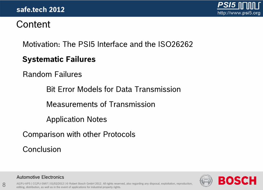
Content
Motivation: The PSI5 Interface and the ISO26262
Systematic Failures
Random Failures
Bit Error Models for Data Transmission
Measurements of Transmission
Application Notes
Comparison with other Protocols
Conclusion

4 AE/PJ-APS | CC/PJ-SMI7 | 01/02/2012 | ©
Robert Bosch GmbH 2012. All rights reserved, also regarding any
disposal, exploitation, reproduction, editing, distribution, as well as in the event of applications for industrial property rights.
safe.tech
2012
Automotive Electronics
Content
Motivation: The PSI5 Interface and the ISO26262
Systematic Failures
Random Failures
Bit Error Models for Data Transmission
Measurements of Transmission
Application Notes
Comparison with other Protocols
Conclusion
5 AE/PJ-APS | CC/PJ-SMI7 | 01/02/2012 | ©
Robert Bosch GmbH 2012. All rights reserved, also regarding any
disposal, exploitation, reproduction, editing, distribution, as well as in the event of applications for industrial property rights.
safe.tech
2012 -
Motivation
Automotive Electronics
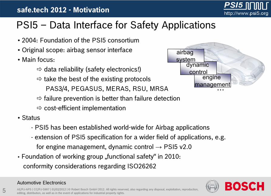
PSI5 –
Data Interface for Safety Applications• 2004: Foundation of the PSI5 consortium• Original scope: airbag sensor interface• Main focus:
data reliability (safety electronics!)
take the best of the existing protocols
PAS3/4, PEGASUS, MERAS, RSU, MRSA
failure prevention is better than failure detection
cost-efficient implementation• Status
- PSI5 has been established world-wide for Airbag applications-
extension of PSI5 specification for a wider field of applications, e.g. for engine management, dynamic control → PSI5 v2.0
•
Foundation of working group „functional safety“
in 2010: conformity considerations regarding ISO26262
engine management
dynamic control
airbag system
...
6 AE/PJ-APS | CC/PJ-SMI7 | 01/02/2012 | ©
Robert Bosch GmbH 2012. All rights reserved, also regarding any
disposal, exploitation, reproduction, editing, distribution, as well as in the event of applications for industrial property rights.
Automotive Electronics
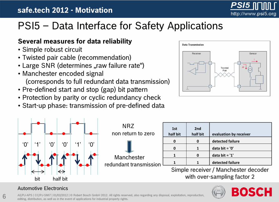
‘1’ ‘1’ ‘0’‘0’‘0’‘0’ ‘1’ ‘1’ ‘0’‘0’‘0’‘0’
Several measures for data reliability• Simple robust circuit• Twisted pair cable (recommendation)• Large SNR (determines „raw failure rate“)•
Manchester encoded signal (corresponds to full redundant data transmission)
• Pre-defined start and stop (gap) bit pattern• Protection by parity or cyclic redundancy check• Start-up phase: transmission of pre-defined data
bit
safe.tech
2012 -
Motivation
half bit
NRZ
Manchester
1st half bit
2nd half bit evaluation by receiver
0 0 detected failure
0 1 data bit = '0'
1 0 data bit = '1'
1 1 detected failure
Simple receiver / Manchester decoder with over-sampling factor 2
PSI5 –
Data Interface for Safety Applications
redundant transmission
non return to zero
7 AE/PJ-APS | CC/PJ-SMI7 | 01/02/2012 | ©
Robert Bosch GmbH 2012. All rights reserved, also regarding any
disposal, exploitation, reproduction, editing, distribution, as well as in the event of applications for industrial property rights.
Automotive Electronics
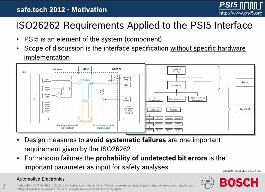
•
Design measures to avoid systematic failures
are one important requirement given by the ISO26262
•
For random failures the probability of undetected bit errors
is the important parameter as input for safety analyses
ISO26262 Requirements Applied to the PSI5 Interface•
PSI5 is an element of the system (component) •
Scope of discussion is the interface specification without specific hardware implementation
Source: ISO26262, BL18 FDIS
Systemarray
System …
E/EComponents
Sensor
Hardware
HardwareComponents
HardwareParts
Software
SoftwareComponents
SoftwareUnits
Controller
Hardware
HardwareComponents
Software
SoftwareComponents
SoftwareUnits
Actuator
Hardware
HardwareComponents
HardwareParts
Software
SoftwareComponents
SoftwareUnits
Communication Other technologyComponents
Item
Element
HardwareParts
shiftregister
Control and timing
supply
“sensor”(see of gates,
mechanic, analog, …)
Receiver SensoruC
receiver logic
“receiver”(external interfacesupply,control
logic, …)
sensor supply
sync generation
depends partly on specific implementation
depends partly on specific implementation
PSI5 data
PSI5 GND
Cable
safe.tech
2012 -
Motivation
8 AE/PJ-APS | CC/PJ-SMI7 | 01/02/2012 | ©
Robert Bosch GmbH 2012. All rights reserved, also regarding any
disposal, exploitation, reproduction, editing, distribution, as well as in the event of applications for industrial property rights.
safe.tech
2012
Automotive Electronics
Content
Motivation: The PSI5 Interface and the ISO26262
Systematic Failures
Random Failures
Bit Error Models for Data Transmission
Measurements of Transmission
Application Notes
Comparison with other Protocols
Conclusion
9 AE/PJ-APS | CC/PJ-SMI7 | 01/02/2012 | ©
Robert Bosch GmbH 2012. All rights reserved, also regarding any
disposal, exploitation, reproduction, editing, distribution, as well as in the event of applications for industrial property rights.
Automotive Electronics
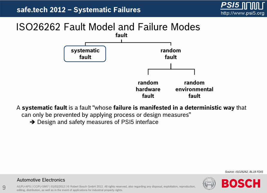
ISO26262 Fault Model and Failure Modes
Source: ISO26262, BL18 FDIS
A systematic fault
is a fault “whose failure is manifested in a deterministic way
that can only be prevented by applying process or design measures” Design and safety measures of PSI5 interface
safe.tech
2012 –
Systematic Failures
fault
systematic
faultrandom
fault
random
environmentalfault
random
hardware
fault
10 AE/PJ-APS | CC/PJ-SMI7 | 01/02/2012 | ©
Robert Bosch GmbH 2012. All rights reserved, also regarding any
disposal, exploitation, reproduction, editing, distribution, as well as in the event of applications for industrial property rights.
safe.tech
2012 –
Systematic Failures
Automotive Electronics
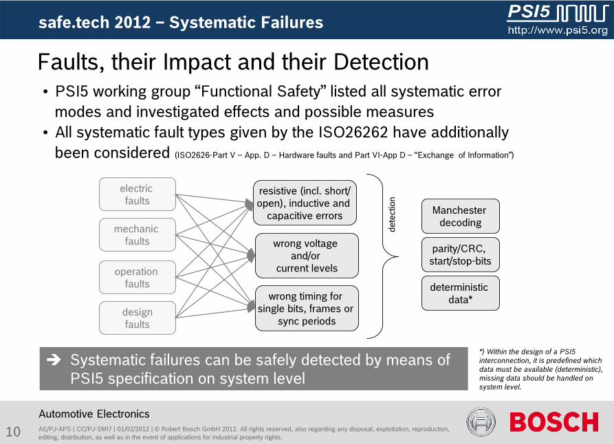
Systematic failures can be safely detected by means of PSI5 specification on system level
•
PSI5 working group “Functional Safety”
listed all systematic error modes and investigated effects and possible measures
•
All systematic fault types given by the ISO26262 have additionally been considered (ISO2626-Part V –
App. D –
Hardware faults and Part VI-App D –
“Exchange of Information”)
*) Within the design of a PSI5 interconnection, it is predefined which data must be available (deterministic), missing data should be handled on system level.
Manchester decoding
deterministic data*
electric faults
mechanic faults
designfaults
resistive (incl. short/open), inductive and
capacitive errors
wrong voltage and/or
current levels
wrong timing for single bits, frames or
sync periods
dete
ctio
n
operation faults
parity/CRC, start/stop-bits
Faults, their Impact and their Detection
11 AE/PJ-APS | CC/PJ-SMI7 | 01/02/2012 | ©
Robert Bosch GmbH 2012. All rights reserved, also regarding any
disposal, exploitation, reproduction, editing, distribution, as well as in the event of applications for industrial property rights.
safe.tech
2012
Automotive Electronics
Content
Motivation: The PSI5 Interface and the ISO26262
Systematic Failures
Random Failures
Bit Error Models for Data Transmission
Measurements of Transmission
Application Notes
Comparison with other Protocols
Conclusion
12 AE/PJ-APS | CC/PJ-SMI7 | 01/02/2012 | ©
Robert Bosch GmbH 2012. All rights reserved, also regarding any
disposal, exploitation, reproduction, editing, distribution, as well as in the event of applications for industrial property rights.
Automotive Electronics
ISO26262 Fault Model and Failure Modes
Source: ISO26262, BL18 FDIS
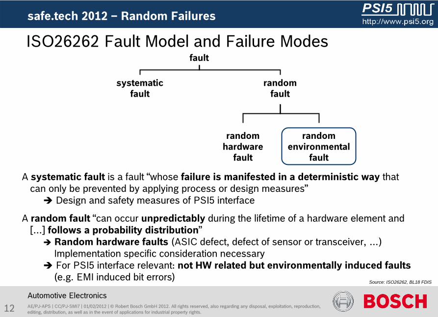
A systematic fault
is a fault “whose failure is manifested in a deterministic way
that can only be prevented by applying process or design measures” Design and safety measures of PSI5 interface
A random fault “can occur unpredictably during the lifetime of a hardware element and […] follows a probability distribution”
Random
hardware
faults
(ASIC defect, defect
of sensor
or
transceiver, …) Implementation
specific
consideration
necessary For PSI5 interface relevant: not HW related but environmentally induced faults
(e.g. EMI induced bit errors)
safe.tech
2012 –
Random Failures
fault
systematic
faultrandom
fault
random
environmentalfault
random
hardware
fault
13 AE/PJ-APS | CC/PJ-SMI7 | 01/02/2012 | ©
Robert Bosch GmbH 2012. All rights reserved, also regarding any
disposal, exploitation, reproduction, editing, distribution, as well as in the event of applications for industrial property rights.
safe.tech
2012 –
Random Failures
Automotive Electronics
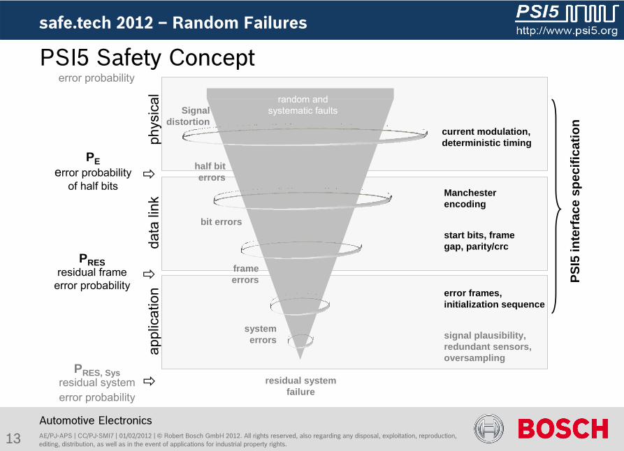
PSI5 Safety Concept
half bit errors
Signal distortion
PSI5
inte
rfac
e sp
ecifi
catio
n
phys
ical
data
link
appl
icat
ion
Manchester encoding
start bits, frame gap, parity/crc
current modulation, deterministic timing
error frames, initialization sequence
signal plausibility, redundant sensors, oversampling
residual system failure
random and systematic faults
bit errors
frame errors
system errors
PRESresidual frame
error probability
PEerror probability
of half bits
PRES, Sysresidual system error probability
error probability
14 AE/PJ-APS | CC/PJ-SMI7 | 01/02/2012 | ©
Robert Bosch GmbH 2012. All rights reserved, also regarding any
disposal, exploitation, reproduction, editing, distribution, as well as in the event of applications for industrial property rights.
safe.tech
2012 –
Random Failures
Automotive Electronics
PSI5 Safety Concept
half bit errors
Signal distortion
PSI5
inte
rfac
e sp
ecifi
catio
n
phys
ical
data
link
appl
icat
ion
Manchester encoding
start bits, frame gap, parity/crc
current modulation, deterministic timing
error frames, initialization sequence
signal plausibility, redundant sensors, oversampling
residual system failure
random and systematic faults
bit errors
frame errors
system errors
PRESresidual frame
error probability
PEerror probability
of half bits
PRES, Sysresidual system error probability
error probability
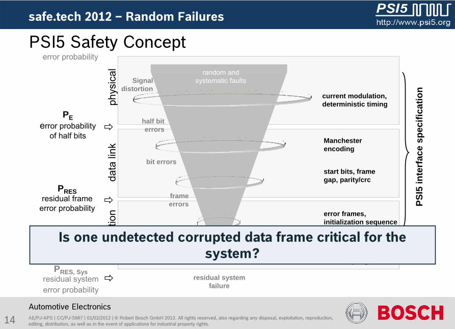
Is one undetected corrupted data frame critical for the system?
15 AE/PJ-APS | CC/PJ-SMI7 | 01/02/2012 | ©
Robert Bosch GmbH 2012. All rights reserved, also regarding any
disposal, exploitation, reproduction, editing, distribution, as well as in the event of applications for industrial property rights.
safe.tech
2012 –
Random Failures
Automotive Electronics
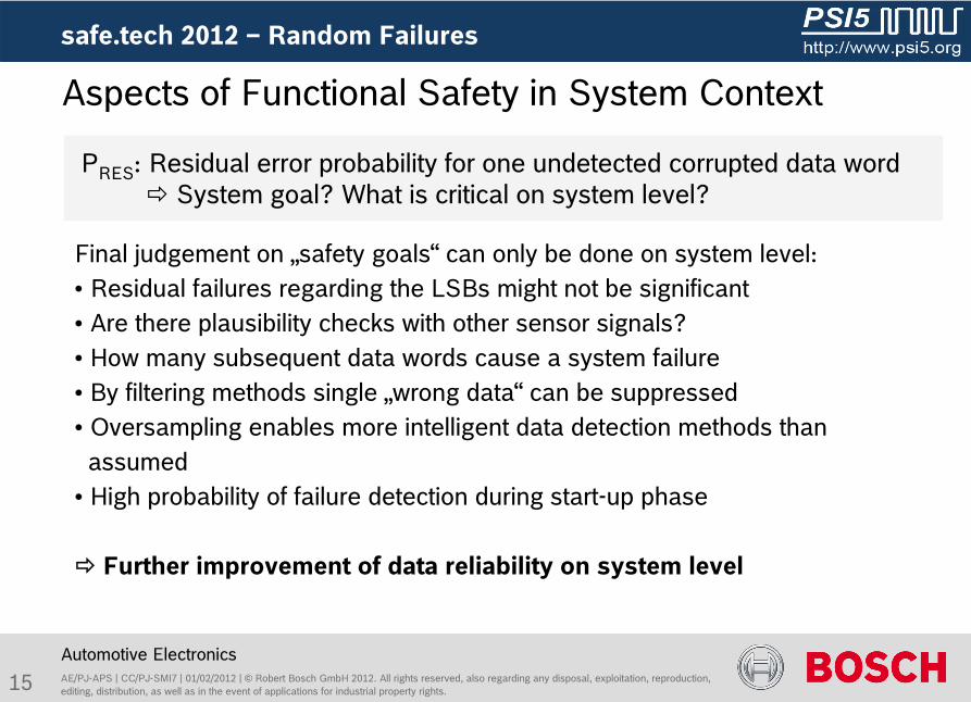
Final judgement
on „safety
goals“
can
only
be
done
on system
level:• Residual failures
regarding
the
LSBs
might
not
be
significant• Are there
plausibility
checks
with
other
sensor
signals?• How
many
subsequent
data
words
cause a system
failure• By
filtering
methods
single
„wrong
data“
can
be
suppressed•
Oversampling
enables
more
intelligent data
detection
methods
than
assumed• High probability
of failure
detection
during
start-up
phase
Further
improvement
of data
reliability
on system
level
PRES
: Residual error
probability
for
one
undetected
corrupted
data
word
System goal? What
is
critical
on system
level?
Aspects of Functional Safety in System Context

16 AE/PJ-APS | CC/PJ-SMI7 | 01/02/2012 | ©
Robert Bosch GmbH 2012. All rights reserved, also regarding any
disposal, exploitation, reproduction, editing, distribution, as well as in the event of applications for industrial property rights.
safe.tech
2012
Automotive Electronics
Content
Motivation: The PSI5 Interface and the ISO26262
Systematic Failures
Random Failures
Bit Error Models for Data Transmission
Measurements of Transmission
Application Notes
Comparison with other Protocols
Conclusion
17 AE/PJ-APS | CC/PJ-SMI7 | 01/02/2012 | ©
Robert Bosch GmbH 2012. All rights reserved, also regarding any
disposal, exploitation, reproduction, editing, distribution, as well as in the event of applications for industrial property rights.
safe.tech
2012 –
Bit Error Models
Automotive Electronics
0 10 0 1
S1 S0 PDnD0
0 10 0 1
S1 S0 PDnD0
0 10 0 1
S1 S0 PDnD0
0 10 0 1
S1 S0 PDnD0
nois
eof
fset
continious
0 10 0 1
S1 S0 PDnD0
0 10 0 1
S1 S0 PDnD0
sino
sida
l
burst
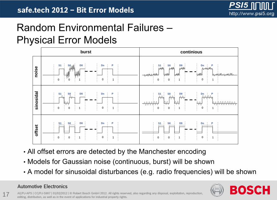
• All offset errors are detected by the Manchester encoding• Models for Gaussian noise (continuous, burst) will be shown• A model for sinusoidal disturbances (e.g. radio frequencies) will be shown
Random Environmental Failures –Physical Error Models
18 AE/PJ-APS | CC/PJ-SMI7 | 01/02/2012 | ©
Robert Bosch GmbH 2012. All rights reserved, also regarding any
disposal, exploitation, reproduction, editing, distribution, as well as in the event of applications for industrial property rights.
safe.tech
2012 –
Bit Error Models
Automotive Electronics
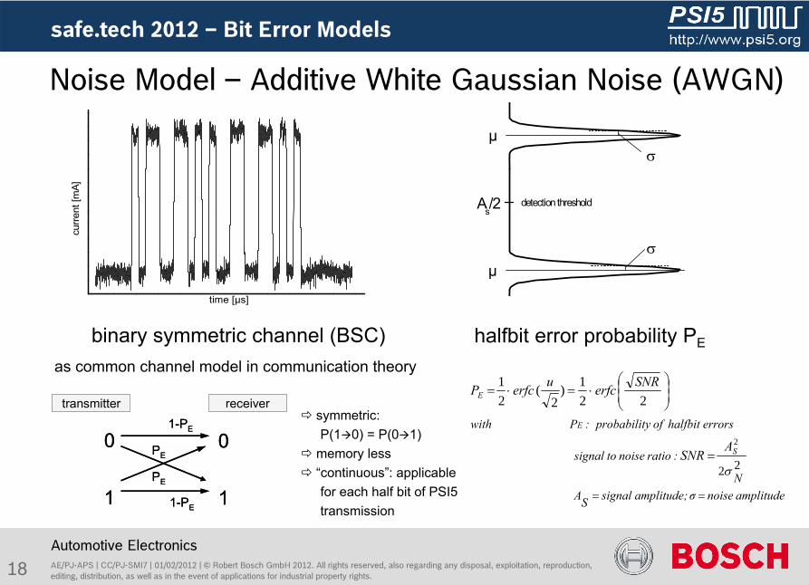
Noise Model –
Additive White Gaussian Noise (AWGN)
halfbit
error probability PE
symmetric: P(10) = P(01)
memory less
“continuous”: applicable for each half bit of PSI5 transmission
binary symmetric channel (BSC) as common channel model in communication theory
curre
nt [m
A]
time [µs]
amplitude noiseσ amplitude; signalSAN
:ratio noise to signal
errors halfbit ofy probabilit :Pwith
S
E
E
ASNR
SNRerfcuerfcP
22
2
221)
2(
21
µ
µ
detection thresholdAs/2
0
1
0
1
transmitter receiver
PE
PE
1-PE
1-PE
0
1
0
1
transmitter receiver
PE
PE
1-PE
1-PE
19 AE/PJ-APS | CC/PJ-SMI7 | 01/02/2012 | ©
Robert Bosch GmbH 2012. All rights reserved, also regarding any
disposal, exploitation, reproduction, editing, distribution, as well as in the event of applications for industrial property rights.
Automotive Electronics
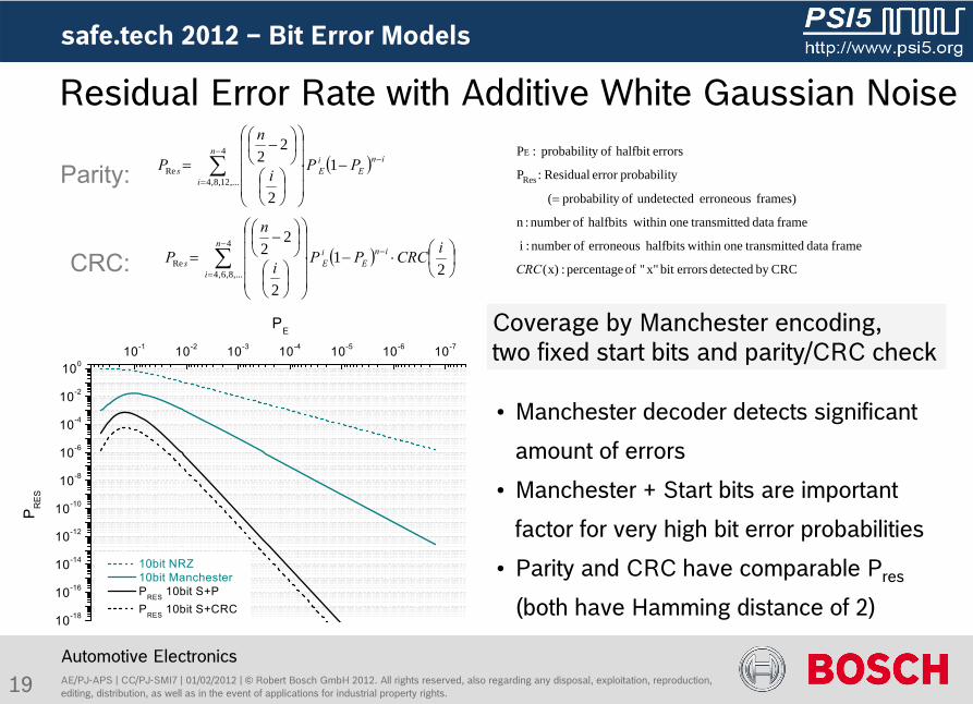
Residual Error Rate with Additive White Gaussian Noise
Coverage by Manchester encoding, two fixed start bits and parity/CRC check
CRCby detected errorsbit x"" of percentage :x)(
frame data ed transmittone within halfbits erroneous ofnumber :i
frame data ed transmittone within halfbits ofnumber :n
frames) erroneous undetected ofy probabilit (
y probabiliterror Residual:P
errorshalfbit ofy probabilit :P
Res
E
CRC
4
,...12,8,4Re 1
2
22n
i
inE
iEs PP
i
n
P
21
2
224
,...8,6,4Re
iCRCPPi
n
Pn
i
inE
iEs
Parity:
CRC:
•
Manchester decoder detects significant
amount of errors
•
Manchester + Start bits are important
factor for very high bit error probabilities
•
Parity and CRC have comparable Pres
(both have Hamming distance of 2)10-18
10-16
10-14
10-12
10-10
10-8
10-6
10-4
10-2
10010-1 10-2 10-3 10-4 10-5 10-6 10-7
PE
10bit NRZ 10bit Manchester PRES 10bit S+P PRES 10bit S+CRC
PR
ES
safe.tech
2012 –
Bit Error Models
20 AE/PJ-APS | CC/PJ-SMI7 | 01/02/2012 | ©
Robert Bosch GmbH 2012. All rights reserved, also regarding any
disposal, exploitation, reproduction, editing, distribution, as well as in the event of applications for industrial property rights.
Automotive Electronics
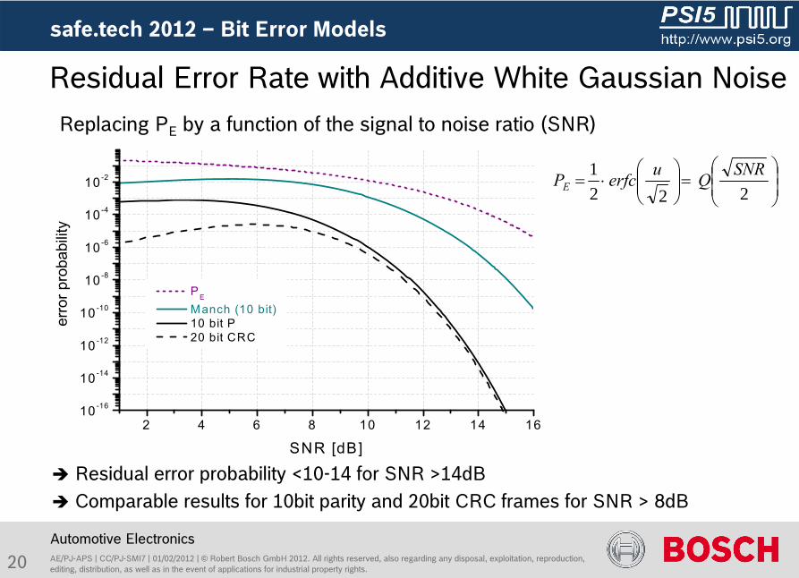
Residual Error Rate with Additive White Gaussian Noise
2221 SNRQuerfcPE
Replacing PE
by a function of the signal to noise ratio (SNR)
Residual error probability <10-14 for SNR >14dB Comparable results for 10bit parity and 20bit CRC frames for SNR
> 8dB
2 4 6 8 10 12 14 1610-16
10-14
10-12
10-10
10-8
10-6
10-4
10-2
PE
Manch (10 bit) 10 bit P 20 bit CRCbi
t erro
r pro
babi
lity
SNR [dB]
safe.tech
2012 –
Bit Error Models
21 AE/PJ-APS | CC/PJ-SMI7 | 01/02/2012 | ©
Robert Bosch GmbH 2012. All rights reserved, also regarding any
disposal, exploitation, reproduction, editing, distribution, as well as in the event of applications for industrial property rights.
Automotive Electronics
Parity / CRC dominated
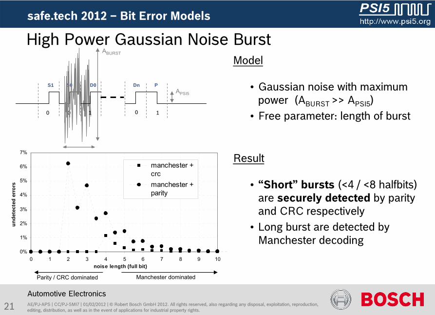
High Power Gaussian Noise Burst
0 10 0 1
S1 S0 PDnD0
ABURST
APSI5
TBURST
0%
1%
2%
3%
4%
5%
6%
7%
0 1 2 3 4 5 6 7 8 9 10noise length (full bit)
unde
tect
ed e
rror
s
manchester +crcmanchester +parity
Model
•
Gaussian noise with maximum power (ABURST >> APSI5
)•
Free parameter: length of burst
Result
•
“Short”
bursts (<4 / <8 halfbits) are securely detected
by parity and CRC respectively
•
Long burst are detected by Manchester decoding
Manchester dominated
safe.tech
2012 –
Bit Error Models
22
4
,...12,8,42
2Re 1
2
22n
i
inE
iE
bg
gbs PP
i
n
pp
P
AE/PJ-APS | CC/PJ-SMI7 | 01/02/2012 | ©
Robert Bosch GmbH 2012. All rights reserved, also regarding any
disposal, exploitation, reproduction, editing, distribution, as well as in the event of applications for industrial property rights.
Automotive Electronics
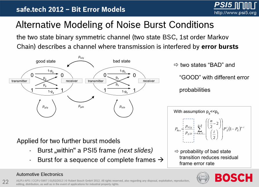
the two state binary symmetric channel (two state BSC, 1st order
Markov Chain) describes a channel where transmission is interfered by error bursts
Applied for two further burst models -
Burst „within“
a PSI5 frame (next slides)-
Burst for a sequence of complete frames
Alternative Modeling of Noise Burst Conditions
two states “BAD”
and
“GOOD”
with different error
probabilities
probability of bad state transition reduces residual frame error rate
With assumption pg
<<pb
0
1
0
1
good state bad state
0
1
0
1
transmitter receiverpg
pg
1-pg
1-pg
pb
pb
1-pb
1-pb
pg2b
pb2g
pg2g pb2b
transmitter receiver
safe.tech
2012 –
Bit Error Models
23 AE/PJ-APS | CC/PJ-SMI7 | 01/02/2012 | ©
Robert Bosch GmbH 2012. All rights reserved, also regarding any
disposal, exploitation, reproduction, editing, distribution, as well as in the event of applications for industrial property rights.
Automotive Electronics
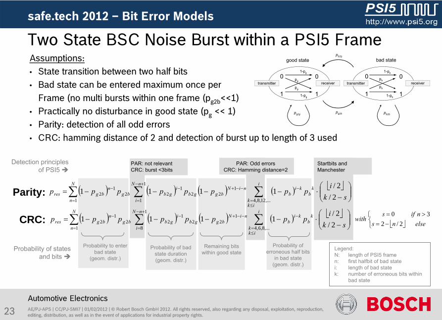
Assumptions:•
State transition between two half bits•
Bad state can be entered maximum once per Frame (no multi bursts within one frame (pg2b
<<1)•
Practically no disturbance in good state (pg
<< 1)•
Parity: detection of all odd errors •
CRC: hamming distance of 2 and detection of burst up to length of 3 used
Two State BSC Noise Burst within a PSI5 Frame
0
1
0
1
good state bad state
0
1
0
1
transmitter receiverpg
pg
1-pg
1-pg
pb
pb
1-pb
1-pb
pg2b
pb2g
pg2g pb2b
transmitter receiver
safe.tech
2012 –
Bit Error Models
Startbits
and Manchester
Probability to enter bad state
(geom. distr.)
Probability of bad state duration(geom. distr.)
Probability of erroneous half bits
in bad state(geom. distr.)
PAR: not relevantCRC: burst <3bits
PAR: Odd errorsCRC: Hamming distance=2
Legend:N:
length of PSI5 framen:
first halfbit
of bad statei:
length of bad statek:
number of erroneous bits within bad state
Parity:
CRC:
Remaining bits within good stateProbability of states
and bits
Detection principles of PSI5
N
n
nN
i
i
ikk
kb
kib
niNbggb
igbbg
nbgres
N
n
nN
i
i
ikk
kb
kib
niNbggb
igbbg
nbgres
ski
pppppppp
ski
pppppppp
1
1
8 ,...8,6,4
122
122
12
1
1
1 ,...12,8,4
122
122
12
2/2/
1111
2/2/
1111
elsensnifs
with2/2
30
24 AE/PJ-APS | CC/PJ-SMI7 | 01/02/2012 | ©
Robert Bosch GmbH 2012. All rights reserved, also regarding any
disposal, exploitation, reproduction, editing, distribution, as well as in the event of applications for industrial property rights.
Automotive Electronics
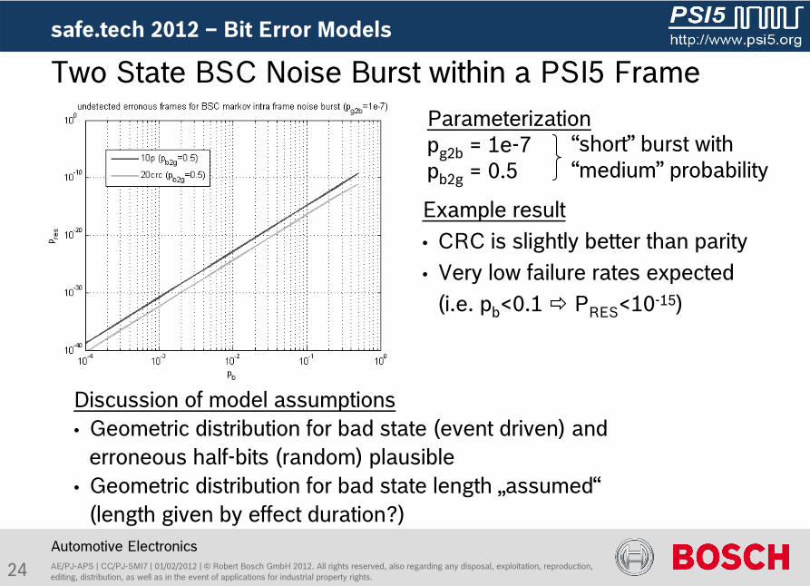
Discussion of model assumptions•
Geometric distribution for bad state (event driven) and erroneous half-bits (random) plausible
•
Geometric distribution for bad state length „assumed“(length given by effect duration?)
Two State BSC Noise Burst within a PSI5 Frame
Example result•
CRC is slightly better than parity•
Very low failure rates expected(i.e. pb
<0.1
PRES
<10-15)
safe.tech
2012 –
Bit Error Models
Parameterizationpg2b
= 1e-7pb2g
= 0.5“short”
burst with “medium”
probability
25
sample points
APSI5
1 1 1 0 1
Parity(CRC)
frame
start bits
1/fPSI5
data bits
ASIN
1/fSIN
sinosidal disturbance
undisturbedPSI5 communication
zero level(mean free)
AE/PJ-APS | CC/PJ-SMI7 | 01/02/2012 | ©
Robert Bosch GmbH 2012. All rights reserved, also regarding any
disposal, exploitation, reproduction, editing, distribution, as well as in the event of applications for industrial property rights.
Automotive Electronics
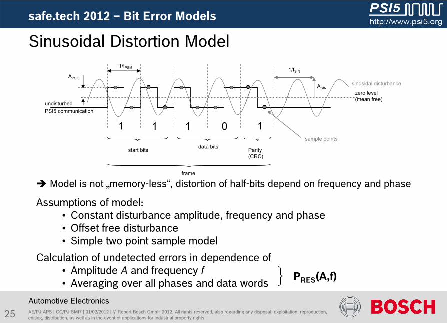
Assumptions of model:•
Constant disturbance amplitude, frequency and phase•
Offset free disturbance•
Simple two point sample model
Calculation of undetected errors in dependence of •
Amplitude A
and frequency f•
Averaging over all phases and data words
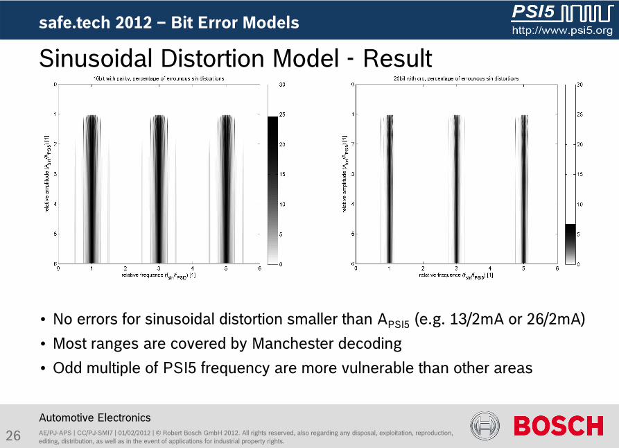
Sinusoidal Distortion Model
Model is not „memory-less“, distortion of half-bits depend on frequency and phase
safe.tech
2012 –
Bit Error Models
PRES
(A,f)
26 AE/PJ-APS | CC/PJ-SMI7 | 01/02/2012 | ©
Robert Bosch GmbH 2012. All rights reserved, also regarding any
disposal, exploitation, reproduction, editing, distribution, as well as in the event of applications for industrial property rights.
Automotive Electronics
Sinusoidal Distortion Model -
Result
•
No errors for sinusoidal distortion smaller than APSI5
(e.g. 13/2mA or 26/2mA)
•
Most ranges are covered by Manchester decoding
•
Odd multiple of PSI5 frequency are more vulnerable than other areas
safe.tech
2012 –
Bit Error Models
27 AE/PJ-APS | CC/PJ-SMI7 | 01/02/2012 | ©
Robert Bosch GmbH 2012. All rights reserved, also regarding any
disposal, exploitation, reproduction, editing, distribution, as well as in the event of applications for industrial property rights.
Automotive Electronics
Offset distortion uncritical for PSI5 interface (Manchester)
Different error models with distinct modeling properties presented
(Noise, Bursts, Sinusoidal)
Protection mechanism of PSI5 interface within error models described
Models can be used during system design to evaluate systems
Parameterization depends on implementation and real life effects
(see next section!)
Conclusion Error Models
safe.tech
2012 –
Bit Error Models

28 AE/PJ-APS | CC/PJ-SMI7 | 01/02/2012 | ©
Robert Bosch GmbH 2012. All rights reserved, also regarding any
disposal, exploitation, reproduction, editing, distribution, as well as in the event of applications for industrial property rights.
safe.tech
2012
Automotive Electronics
Content
Motivation: The PSI5 Interface and the ISO26262
Systematic Failures
Random Failures
Bit Error Models for Data Transmission
Measurements of Transmission
Application notes
Comparison with other Protocols
Conclusion
29 AE/PJ-APS | CC/PJ-SMI7 | 01/02/2012 | ©
Robert Bosch GmbH 2012. All rights reserved, also regarding any
disposal, exploitation, reproduction, editing, distribution, as well as in the event of applications for industrial property rights.
safe.tech
2012 -
Measurements
Automotive Electronics
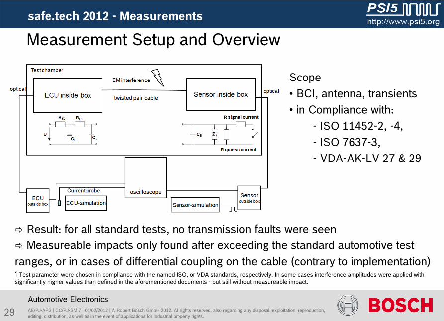
Measurement Setup and Overview
*) Test parameter were chosen in compliance with the named ISO, or VDA standards, respectively. In some cases interference amplitudes were applied with significantly higher values than defined in the aforementioned documents -
but still without measureable impact.
Result: for all standard tests, no transmission faults were seen
Measureable impacts only found after exceeding the standard automotive test ranges, or in cases of differential coupling on the cable (contrary to implementation)
Scope• BCI, antenna, transients• in Compliance with:
-
ISO 11452-2, -4, - ISO 7637-3, -
VDA-AK-LV 27 & 29
30 AE/PJ-APS | CC/PJ-SMI7 | 01/02/2012 | ©
Robert Bosch GmbH 2012. All rights reserved, also regarding any
disposal, exploitation, reproduction, editing, distribution, as well as in the event of applications for industrial property rights.
safe.tech
2012 -
Measurements
Automotive Electronics
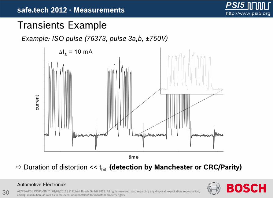
Duration of distortion << tbit
(detection by Manchester or CRC/Parity)
Transients ExampleExample: ISO pulse (76373, pulse 3a,b, ±750V)
no data failure detected in experiments
(depends on receiver implementation)
cu
rren
t
time
IS = 10 mA
31 AE/PJ-APS | CC/PJ-SMI7 | 01/02/2012 | ©
Robert Bosch GmbH 2012. All rights reserved, also regarding any
disposal, exploitation, reproduction, editing, distribution, as well as in the event of applications for industrial property rights.
safe.tech
2012 -
Measurements
Automotive Electronics
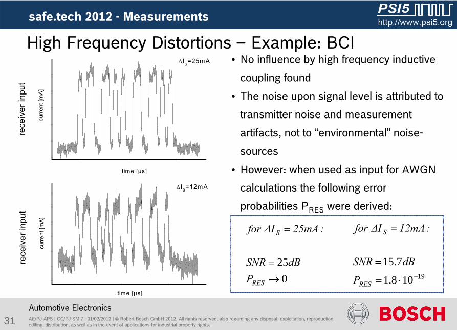
IS=12mA
curre
nt [m
A]
time [µs]
IS=25mA
time [µs]
curre
nt [m
A]
•
No influence by high frequency inductive
coupling found
•
The noise upon signal level is attributed to
transmitter noise and measurement
artifacts, not to “environmental”
noise-
sources
•
However: when used as input for AWGN
calculations the following
error
probabilities PRES
were derived:
19108.1
7.15
RES
S
P
dBSNR
:12mAΔI for
High Frequency Distortions –
Example: BCI
025
RES
S
PdBSNR
:25mAΔI for
rece
iver
inpu
tre
ceiv
er in
put
32 AE/PJ-APS | CC/PJ-SMI7 | 01/02/2012 | ©
Robert Bosch GmbH 2012. All rights reserved, also regarding any
disposal, exploitation, reproduction, editing, distribution, as well as in the event of applications for industrial property rights.
safe.tech
2012
Automotive Electronics
Content
Motivation: The PSI5 Interface and the ISO26262
Systematic Failures
Random Failures
Bit Error Models for Data Transmission
Measurements of Transmission
Application Notes
Comparison with other Protocols
Conclusion
33 AE/PJ-APS | CC/PJ-SMI7 | 01/02/2012 | ©
Robert Bosch GmbH 2012. All rights reserved, also regarding any
disposal, exploitation, reproduction, editing, distribution, as well as in the event of applications for industrial property rights.
safe.tech
2012 –
Application Notes
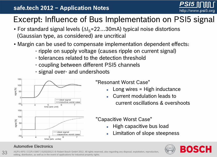
“Resonant Worst Case"
Long wires = High inductance
Current modulation leads to
current oscillations & overshoots
"Capacitive Worst Case"
High capacitive bus load
Limitation of slope steepness
Automotive Electronics
Excerpt: Influence of Bus Implementation on PSI5 signal•
For standard signal levels (IS
=22…30mA) typical noise distortions (Gaussian type, as considered) are uncritical
•
Margin can be used to compensate implementation dependent effects:
-
ripple on supply voltage (causes ripple on current signal)
-
tolerances related to the detection threshold -
coupling between different PSI5 channels
-
signal over-
and undershoots
34 AE/PJ-APS | CC/PJ-SMI7 | 01/02/2012 | ©
Robert Bosch GmbH 2012. All rights reserved, also regarding any
disposal, exploitation, reproduction, editing, distribution, as well as in the event of applications for industrial property rights.
safe.tech
2012 –
Application Notes
Automotive Electronics
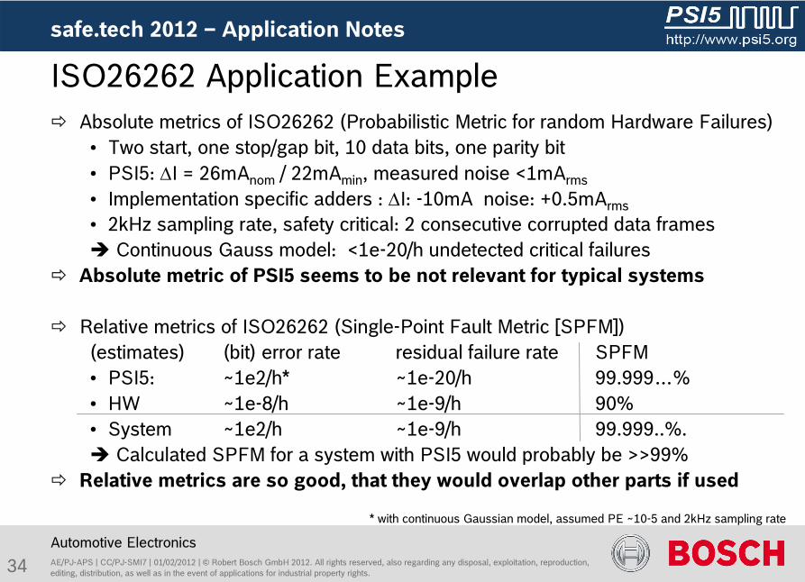
Absolute metrics of ISO26262 (Probabilistic Metric for random Hardware Failures)•
Two start, one stop/gap bit, 10 data bits, one parity bit •
PSI5: I = 26mAnom
/ 22mAmin
, measured noise <1mArms
•
Implementation specific adders : I: -10mA noise: +0.5mArms
•
2kHz sampling rate, safety critical: 2 consecutive corrupted data frames Continuous Gauss model: <1e-20/h undetected critical failures
Absolute metric of PSI5 seems to be not relevant for typical systems
Relative metrics of ISO26262 (Single-Point Fault Metric [SPFM])(estimates) (bit) error rate
residual failure rate
SPFM•
PSI5: ~1e2/h*
~1e-20/h
99.999…%•
HW
~1e-8/h ~1e-9/h
90%•
System
~1e2/h
~1e-9/h
99.999..%. Calculated SPFM for a system with PSI5 would probably be >>99%
Relative metrics are so good, that they would overlap other parts if used
ISO26262 Application Example
* with continuous Gaussian model, assumed PE ~10-5 and 2kHz sampling rate
35 AE/PJ-APS | CC/PJ-SMI7 | 01/02/2012 | ©
Robert Bosch GmbH 2012. All rights reserved, also regarding any
disposal, exploitation, reproduction, editing, distribution, as well as in the event of applications for industrial property rights.
safe.tech
2012 –
Measurements & Application Notes
Automotive Electronics
EMI robustness of the PSI5 interface was shown
No data failures detected due to robust physical layer
Residual error probabilities for measured PSI5 signals PRES
<<10-19
Be careful when using the PSI5 failure rates for ISO26262 metric
calculations
Summary Measurement Results and Application Notes

36 AE/PJ-APS | CC/PJ-SMI7 | 01/02/2012 | ©
Robert Bosch GmbH 2012. All rights reserved, also regarding any
disposal, exploitation, reproduction, editing, distribution, as well as in the event of applications for industrial property rights.
safe.tech
2012
Automotive Electronics
Content
Motivation: The PSI5 Interface and the ISO26262
Systematic Failures
Random Failures
Bit Error Models for Data Transmission
Measurements of Transmission
Application Notes
Comparison with other Protocols
Conclusion
37 AE/PJ-APS | CC/PJ-SMI7 | 01/02/2012 | ©
Robert Bosch GmbH 2012. All rights reserved, also regarding any
disposal, exploitation, reproduction, editing, distribution, as well as in the event of applications for industrial property rights.
safe.tech
2012 -
Comparison
Automotive Electronics
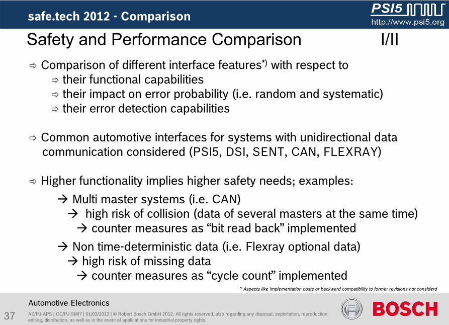
Safety and Performance Comparison
I/II Comparison of different interface features*)
with respect to their functional capabilities their impact on error probability (i.e. random and systematic) their error detection capabilities
Common automotive interfaces for systems with unidirectional data communication considered (PSI5, DSI, SENT, CAN, FLEXRAY)
Higher functionality implies higher safety needs; examples: Multi master systems (i.e. CAN)
high risk of collision (data of several masters at the same time) counter measures as “bit read back”
implemented Non time-deterministic data (i.e. Flexray
optional data) high risk of missing data counter measures as “cycle count”
implemented*)
Aspects like Implementation costs or backward compatibility to former revisions not considerd
safe.tech
2012 -
Comparison
38 AE/PJ-APS | CC/PJ-SMI7 | 01/02/2012 | ©
Robert Bosch GmbH 2012. All rights reserved, also regarding any
disposal, exploitation, reproduction, editing, distribution, as well as in the event of applications for industrial property rights.
safe.tech
2012 -
Comparison
Automotive Electronics
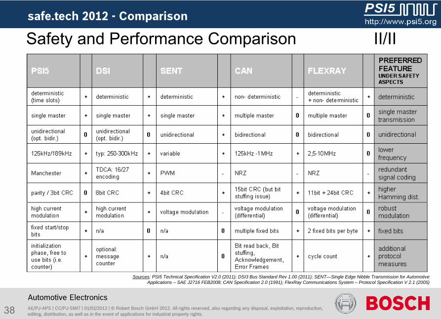
Safety and Performance Comparison
II/II
Sources: PSI5 Technical Specification V2.0 (2011); DSI3 Bus Standard Rev 1.00 (2011); SENT—Single Edge Nibble Transmission for Automotive Applications – SAE J2716 FEB2008; CAN Specification 2.0 (1991); FlexRay Communications System – Protocol Specification V 2.1 (2005)
39
Comparison between interfaces needs to consider performance and
safety features (higher performance needs distinct safety features)
The safety concept of the PSI5 is “State of the Art”
considering its
functional capabilities (i.e. no need of bit read back, frame counter, …)
For systems which need advanced functionality (i.e. multi node
bidirectional communication, ensured availability, ….) protocols like
CAN, Flexray
or others, which therefore feature additional safety
mechanisms, should be used
AE/PJ-APS | CC/PJ-SMI7 | 01/02/2012 | ©
Robert Bosch GmbH 2012. All rights reserved, also regarding any
disposal, exploitation, reproduction, editing, distribution, as well as in the event of applications for industrial property rights.
Automotive Electronics
Comparing PSI5 to Other Interfaces
safe.tech
2012 -
Comparison

40 AE/PJ-APS | CC/PJ-SMI7 | 01/02/2012 | ©
Robert Bosch GmbH 2012. All rights reserved, also regarding any
disposal, exploitation, reproduction, editing, distribution, as well as in the event of applications for industrial property rights.
safe.tech
2012
Automotive Electronics
Content
Motivation: The PSI5 Interface and the ISO26262
Systematic Failures
Random Failures
Bit Error Models for Data transmission
Measurements of Transmission
Application Notes
Comparison with other Protocols
Conclusion
41 AE/PJ-APS | CC/PJ-SMI7 | 01/02/2012 | ©
Robert Bosch GmbH 2012. All rights reserved, also regarding any
disposal, exploitation, reproduction, editing, distribution, as well as in the event of applications for industrial property rights.
safe.tech
2012 -
Conclusion
Automotive Electronics
Conclusion
Systematic failure prevention was one main focus of PSI5 development
The PSI5 interface shows very high data reliability:
residual error probability <10-14
for SNR >14dB
Parity check sufficient for small data words, CRC recommended for large frames
10bit parity and 20bit CRC frames have comparable PRES for SNR > 8dB
PSI5 interface is comparable in safety to other automotive interfaces and a state
of the art sensor interface
Presented methods and argumentations support conformity considerations
regarding ISO26262 for systems rated up to ASIL D.
42 AE/PJ-APS | CC/PJ-SMI7 | 01/02/2012 | ©
Robert Bosch GmbH 2012. All rights reserved, also regarding any
disposal, exploitation, reproduction, editing, distribution, as well as in the event of applications for industrial property rights.
safe.tech
2012 -
Conclusion
Automotive Electronics
This presentation was made possible by valuable
contributions from the PSI5 Working Group “Functional Safety”; namely
Acknowledgements
D. Daecke (Bosch), T. Dittfeld
(Infineon), J.P. Ebersol
(Autoliv),
M. Fischer (TRW), A. Gesell (Continental), M. Jordan (Freescale),
R. Kewitz
(IHR), V. Neumann (IHR), F. Ocker (TRW),
F. Plötzl
(Continental), J. Seidel (Bosch), T. Weiss (Bosch)
1
CONSIDERATIONS ON FUNCTIONAL SAFETY OF THE PSI5 INTERFACE IN THE SCOPE OF THE ISO26262
M. Baus, A. Hepp, J. Seidel, T. Weiss, Robert Bosch GmbH, Germany
A. Gesell, F. Ploetz, Continental, Germany
J.-P. Ebersohl, Autoliv Electronics Europe, France
M. Fischer, TRW Automotive GmbH, Germany
Abstract
With PSI5 (peripheral sensor interface) a standard for data transmission in
automotive safety applications has been established. Originally designed for
airbag applications, the new specification 2.0 covers additional fields of
application like engine management and vehicle dynamics. In this paper
several aspects of PSI5 related to the road vehicles functional safety
standard (ISO26262) are discussed.
The safety mechanisms of the PSI5 interface are described and its particular
ability to handle systematic errors is shown. Different error models are
discussed and compared to measurements. Reference is given to other standard
interfaces used in automotive E/E networks.
Results and conclusions support conformity considerations regarding ISO26262
for systems rated up to ASIL D.
Keywords: PSI5, Communication Protocol, Manchester, bit error probability,
ISO26262, Functional Safety
2
1 Introduction ......................................................... 3 1.1 ISO26262........................................................... 3
2 PSI5 Interface ....................................................... 4 2.1 Concept............................................................ 4 2.2 Measures for data reliability...................................... 5 2.3 Parity and cyclic redundancy check (CRC) detection capabilities.... 7
3 ISO26262 requirements to PSI5 ........................................ 8 3.1 Considerations on systematic faults of the PSI5 interface.......... 9 3.2 Systematic fault considerations required by the ISO26262.......... 11 3.3 Systematic faults in comparison with other automotive interfaces.. 12 3.4 Random faults..................................................... 13
4 Bit error models .................................................... 14 4.1 Continuous Gaussian white noise................................... 15 4.2 Gaussian noise burst model........................................ 19 4.2.1 Burst for a sequence of complete frames....................... 19 4.2.2 Burst within a PSI5 frame..................................... 21
4.3 High power Gaussian noise burst................................... 22 4.4 Sinusoidal continuous disturbances................................ 24
5 Measurements ........................................................ 27 6 PSI5 interface integration .......................................... 32 6.1 Hardware implementation aspects besides EMI....................... 32 6.2 Calculating residual error rates for an actual system............. 33 6.3 ISO26262 conformal calculation of relative metrics................ 34
7 Summary and Conclusions ............................................. 35 8 Acknowledgments ..................................................... 37
3
1 Introduction
The PSI5 consortium was founded in 2004. The original scope was the
development of a robust interface between sensors and electric control units
(ECU) for airbag applications.
Dealing with safety electronics – wrong data may cause a non-deployment of
an airbag during a crash, or an airbag deployment without crash – a high
data reliability was the main focus within the PSI5 consortium. Therefore,
many existing interface protocols, like PAS3/4, PEGASUS, MERAS, RSU or MRSA
have been considered[OHL], taking the best of each. One important aspect for
the design of PSI5 was that failure prevention is better than failure
detection.
Since then, PSI5 has been established world-wide for airbag applications.
Now, the PSI5 specification has been extended for a wider field of
applications. The specification version 2.0 contains extensions for engine
management and dynamic control applications [PSI5], [REIM], [BOCK].
In 2010 the working group “functional safety” was founded within the PSI5
consortium. Main target was to give guidance for conformity considerations
regarding the ISO26262 standard of functional safety for road vehicles
[ISO], also with respect to the new applications that require a partly
widened parameter field.
1.1 ISO26262
The ISO26262 standard is a vehicle to master the permanently increasing
safety requirements within the automotive area. With the final release of
the ISO standard, published in 2011, the safety requirements and methodology
described within are universally claimed not only to system manufacturers
but also to each part of the system development process, i.e. to each (sub-)
supplier in the whole production chain.
This paper intends to give support for those who develop automotive systems
or components that use the PSI5 interface for communication between
peripheral sensors/actuators and the control unit. Its goal is to give basic
technical considerations and conclusions that can be used for application
specific safety analyses.
4
An evidence of compliance with or violation of safety goals cannot be given
from this reflection level, neither a common statement of residual random
hardware failure rates of the PSI5 interface because detailed system
requirements and knowledge about system architecture are necessary for
validation.
2 PSI5 Interface
This chapter describes the main aspects of PSI5, its measures to provide a
robust interface and details about its protection mechanisms.
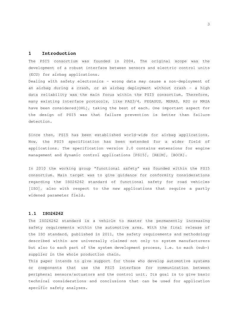
2.1 Concept
PSI5 connects sensors or actuators to a control unit on the basis of a 2-
wire cable. The cable serves both for power supply of the sensors or
actuators and for data communication. For that purpose the ECU transmits so-
called “sync-pulses” by modulation of the voltage. The sensor or actuator
responds within predefined time slots with current-modulated data. A
schematic of the interface is depicted in Figure 1. Accordingly, PSI5 allows
a cost-efficient implementation.
Figure 1 Implementation scheme of the PSI5 interface
Optionally, data can be transmitted also asynchronously: Data words are sent
in specified intervals. Sync pulses are not required in that case.
For bidirectional communication specific sync pulse patterns are used to
transmit commands to the sensors/actuators, e.g. for sensor addressing in
case of a daisy chain bus, the configuration of bus devices or the
activation of actuators.
5
Synchronous transmission enables time-division multiple-access, i.e. the
data words of various sensors or actuators are assigned to different time
slots. This way several sensors (actuators) can share one cable. In
principle, PSI5 supports parallel and daisy chain bus, the former in star
and parallel bus topologies, the latter in parallel mode.
2.2 Measures for data reliability
As mentioned above, data reliability is the key requirement of PSI5. On the
physical layer this is realized by a simple concept; high signal current
levels with a maximum level of 30mA provide a large signal to noise ratio
(SNR) and hence, good electromagnetic compatibility. Besides, the twisted
pair cable compensates for distortions within a homogenous field.
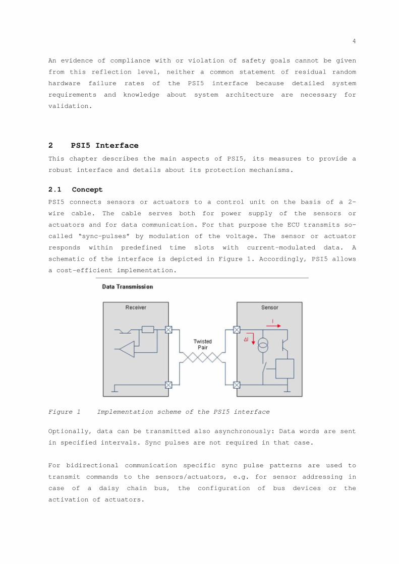
On the data link layer there are several further measures to guarantee a
high transmission performance: The signal data is Manchester-encoded, i.e.
most of all potential signal distortion can be detected by missing or
implausible signal transitions. As shown in Figure 2, compared to a non
return to zero (NRZ) signal, Manchester encoding corresponds to a fully
redundant transmission: Data information is given by transitions instead of
signal levels.
Figure 2 Redundant Data Transmission of Manchester decoded data
compared to a NRZ signal
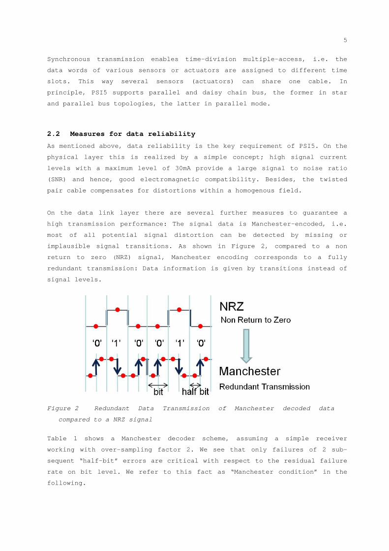
Table 1 shows a Manchester decoder scheme, assuming a simple receiver
working with over-sampling factor 2. We see that only failures of 2 sub-
sequent “half-bit” errors are critical with respect to the residual failure
rate on bit level. We refer to this fact as “Manchester condition” in the
following.
6
Table 1 Manchester decoder scheme
In addition, data words are protected by a parity bit or by cyclic
redundancy check (CRC) bits. By means of start and stop bits (defined
minimum gap between two frames) timing failures can be detected.
Furthermore, failure detection can be enhanced by evaluating data during
initialization phase.
half bit errors
Signal distortion
PSI5
inte
rfac
e sp
ecifi
catio
n
phys
ica
lda
ta li
nkap
plic
atio
n
Manchester Encoding
start bits, frame gap, parity/crc
current modulation, deterministic timing
error frames, initialization sequence
signal plausibility, redundant sensors, oversampling
residual system failure
random and systematic faults
bit errors
frame errors
system errors
PRESresidual frame
error probability
PEerror Probability
of half bits
PRES, SysResidual system error probability
Error probability
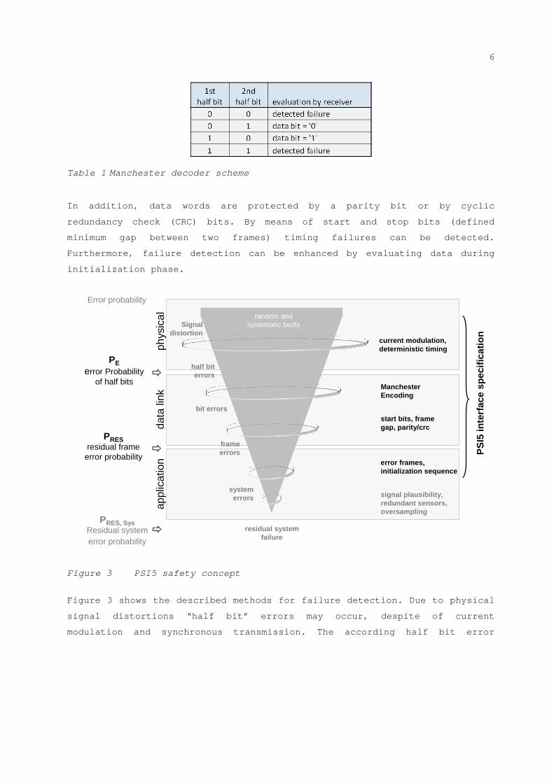
Figure 3 PSI5 safety concept
Figure 3 shows the described methods for failure detection. Due to physical
signal distortions “half bit” errors may occur, despite of current
modulation and synchronous transmission. The according half bit error
7
probability is called PE1. After the Manchester decoding full bit errors
might remain undetected. Applying additional measures on data link layer the
probability for residual frame errors – PRES – is further reduced. Finally,
there are even more means on system level for failure detection, resulting
in the residual system error probability. Furthermore, residual failures
regarding LSBs might not be significant, failure detection could be enhanced
on the basis of plausibility checks with other sensor signals, one single
frame error may not cause a system failure, single frame failures can be
suppressed by filtering methods and higher oversampling enables smarter data
detection methods than the ones assumed above.
This paper addresses the residual frame error probability; a final judgment
on “safety goals” cannot be given here. It can only be done on a system
level.
Summarizing this list, there is additional space for improvement of data
reliability on a system level. Additionally, the mentioned methods also
contribute significantly to the avoidance of systematic faults as will be
discussed in more detail in chapter 3.
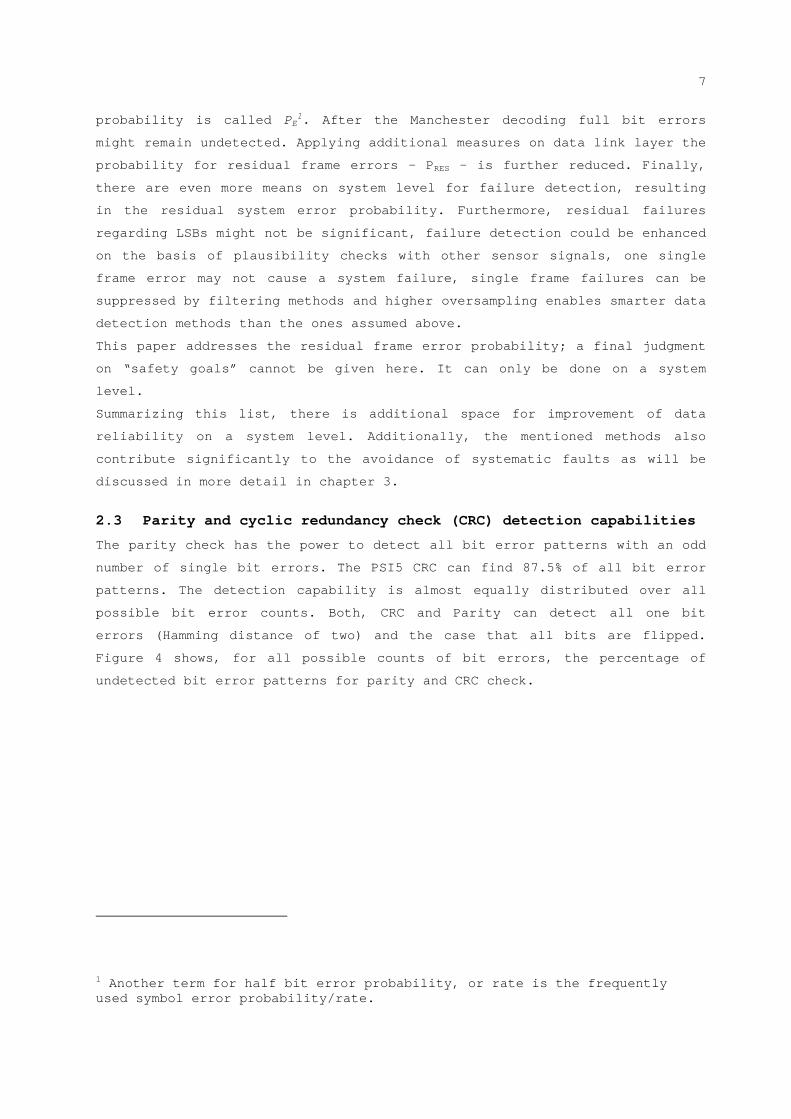
2.3 Parity and cyclic redundancy check (CRC) detection capabilities
The parity check has the power to detect all bit error patterns with an odd
number of single bit errors. The PSI5 CRC can find 87.5% of all bit error
patterns. The detection capability is almost equally distributed over all
possible bit error counts. Both, CRC and Parity can detect all one bit
errors (Hamming distance of two) and the case that all bits are flipped.
Figure 4 shows, for all possible counts of bit errors, the percentage of
undetected bit error patterns for parity and CRC check.
1 Another term for half bit error probability, or rate is the frequently used symbol error probability/rate.
8
0%
20%
40%
60%
80%
100%
0 5 10 15 20
no of disturbed bits
un
de
tect
ed
co
mb
ina
tion
s 20bit crc
10bit parity
Figure 4 Single bit error detection capabilities of parity and CRC
mechanisms
Additionally, the CRC can detect a high number of bit burst errors. A bit
burst of the length n is an error where up to n consecutive bit errors are
present. For the PSI5 CRC the following three properties are given [FRIE]:
100% of all bit burst up to n=3 are detected
75% of all bit burst up to n=4 are detected
87.5% of all bit burst of n>4 are detected
The properties of the parity and CRC checksum respectively will be used in
later sections. The ISO conformity will be discussed in chapter 3.2. Other
frame length and checksum combinations can be easily derived.
3 ISO26262 requirements to PSI5
As mentioned above, it is not the intention of this paper to make a
statement concerning the safety classification of the PSI5 interface itself,
since such a statement must be done for the whole system and requires
detailed knowledge about its requirements and architecture. Thus, it is
necessary to define certain prerequisites for the following discussion. The
first and essential conclusion is that the PSI5 interface is an element of
the system according to the ISO26262. Therefore systematic failures have to
be considered and prevented. The failure rate of the interface is the
important parameter for safety metric calculations.
The ISO26262 standard distinguishes between systematic and random faults. A
systematic fault is a fault “whose failure is manifested in a deterministic
way that can only be prevented by applying process or design measures”
whereas a random hardware fault “can occur unpredictably during the lifetime
9
of a hardware element and […] follows a probability distribution”. The
ISO26262 only knows random failures for hardware elements. However the PSI5
communication can not be considered as a hardware element, but might also be
a source of errors in certain circumstances. Electromagnetic interference,
for example, is also an unpredictable fault following a certain probability
distribution over lifetime resulting from an external influence which is not
related to damaged hardware. This kind of fault is classified as a random
environmental fault since it is caused by a defined environmental
circumstance in an unpredictable way. In contrast, a random hardware fault
would be, for example, a damaged EMI protection capacitor. The
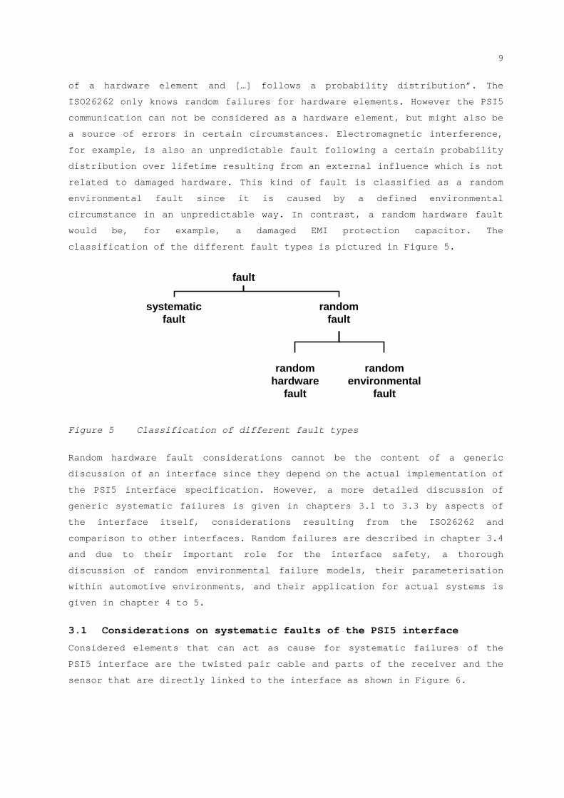
classification of the different fault types is pictured in Figure 5.
fault
systematicfault
randomfault
randomenvironmental
fault
randomhardware
fault
Figure 5 Classification of different fault types
Random hardware fault considerations cannot be the content of a generic
discussion of an interface since they depend on the actual implementation of
the PSI5 interface specification. However, a more detailed discussion of
generic systematic failures is given in chapters 3.1 to 3.3 by aspects of
the interface itself, considerations resulting from the ISO26262 and
comparison to other interfaces. Random failures are described in chapter 3.4
and due to their important role for the interface safety, a thorough
discussion of random environmental failure models, their parameterisation
within automotive environments, and their application for actual systems is
given in chapter 4 to 5.
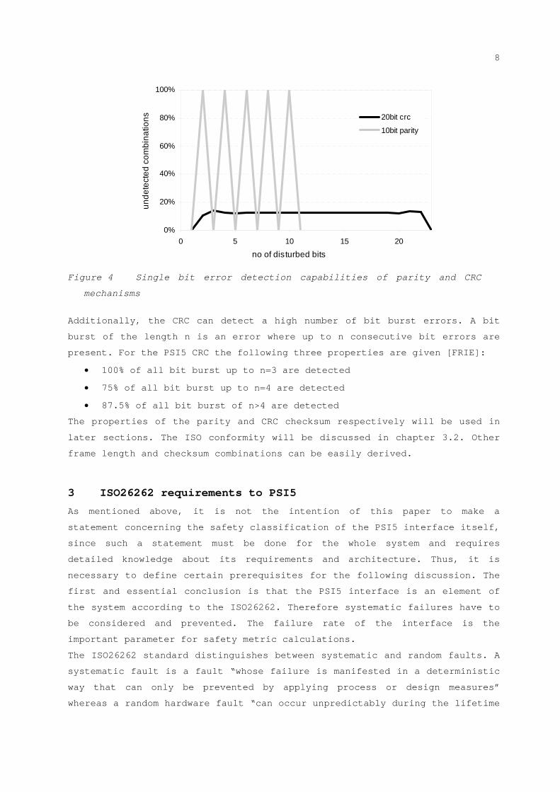
3.1 Considerations on systematic faults of the PSI5 interface
Considered elements that can act as cause for systematic failures of the
PSI5 interface are the twisted pair cable and parts of the receiver and the
sensor that are directly linked to the interface as shown in Figure 6.
10
scope of PSI5 safety consideration within PSI5 consortium
shiftregister
control and timing
supply
“sensor”(see of gates, mechanic, analog, …)
Receiver SensoruC
receiver logic
“receiver” (external interface supply, control logic, …)
sensor supply
sync generation
depends partly on specific implementation
depends partly on specific implementation
PSI5 data
PSI5 GND
Cable
Figure 6 Scheme of the PSI5 interface and visualization of the
considered scope
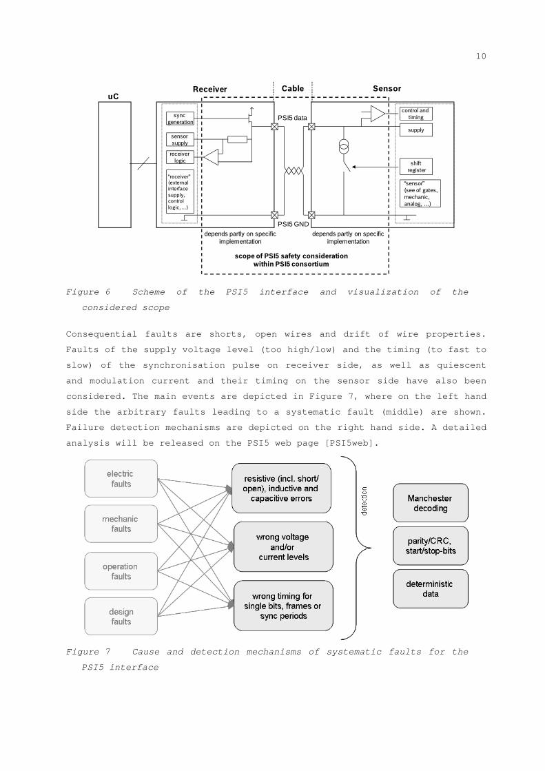
Consequential faults are shorts, open wires and drift of wire properties.
Faults of the supply voltage level (too high/low) and the timing (to fast to
slow) of the synchronisation pulse on receiver side, as well as quiescent
and modulation current and their timing on the sensor side have also been
considered. The main events are depicted in Figure 7, where on the left hand
side the arbitrary faults leading to a systematic fault (middle) are shown.
Failure detection mechanisms are depicted on the right hand side. A detailed
analysis will be released on the PSI5 web page [PSI5web].
Figure 7 Cause and detection mechanisms of systematic faults for the
PSI5 interface

11
As stated above, the faults can only be assessed on functional level and the
detailed hardware fault analysis has to be done for the final implementation
of the interface. However, the PSI5 interface specification has been
analyzed for its ability to cope with several generic faults. With the
following results:
For synchronous operation modes all systematic faults will be detected
if the receiver can detect a Manchester error and a missing frame (due
to a deterministic data flow). The parity/CRC check is not even needed
to detect these faults.
For Bidirectional communication the additional CRC is needed to detect
a missing or wrongly added / detected sync pulse.
An unintended sensor restart due to a low voltage or short time supply
interruption will lead again to sensor initialization. Initialisation
data is marked specially and will thus not lead to a safety critical
state. However, the temporary unavailability of the sensor signals
should not affect the system.
3.2 Systematic fault considerations required by the ISO26262
The ISO26262 gives several hints on failure modes that should be analysed
and even proposals on prevention mechanisms are given (see ISO26262, Part 5
Appendix D, and Part 6, Appendix D). All given hints have been analysed in
the context of the PSI5 interface. Due to the simple and thus robust design
specification of the PSI5 interface, it was found that all aspects are
covered, if applicable. A complete listing is given on the PSI5 web pages
[PSI5web].
One requirement of the ISO26262, which is often discussed, is the question
of the Hamming distance that is needed for failsafe communication. For the
Hamming distance of the PSI5 interface, not only the parity and CRC
mechanism respectively, but also the Manchester encoding has to be
considered, leading to an effective distance of 3. However, even a “Medium
diagnostic coverage: Hamming distance of 3 or more” [ISO] does not
necessarily suggest an insufficient interface. For systematic faults it was
shown in section 3.1 that even a one Hamming distance would be sufficient to
cover all systematic faults. For random faults the probability of a fault
has significant influence on the system performance. For a, not yet
invented, wireless airbag firing switch a hamming distance of 4 may not even
be enough, while for on board serial communications within an engine control
unit even unprotected data still is state of the art and sufficient to
guarantee a safe system.
12
Another suggestion from the ISO26262 is the insertion of a frame counter.
Even if the PSI5 interface provides the possibility to use such a counter,
it is unnecessary in many cases and may be omitted in favour of a higher
protocol payload. The PSI5 information is transmitted in a deterministic
way, missing data can easily be detected by a reasonable receiver design.
Switching information of two independent sensors within a PSI5 bus is
impossible. Mixed signals due to broken hardware should be avoided by a
robust hardware design.
3.3 Systematic faults in comparison with other automotive interfaces
To judge the safety performance of the PSI5 interface, it is compared with
other interfaces used in safety related automotive E/E systems. The safety
of an interface is not only given by its safety mechanisms. Also the
performance capabilities have to be considered. A simple deterministic
point-2-point connection does not need the same safety mechanism as a multi
master non deterministic high speed interface. Also the physical properties
and the environment in which an interface is used are important to evaluate
the power of the safety mechanism. A wireless connection of four tire
pressure sensors within a fleet of vehicles might be much more error prone
than a local hard wired and shielded connection. In the following comparison
mainly the scope of operation where PSI5 is used is considered. In operation
areas that require higher functionality, which is provided by other
protocols like CAN or Flexray, additional and more sophisticated safety
measures might be needed. However, within a system where an unidirectional
communication is needed, using an interface with a multi master
functionality increases the complexity unnecessarily and should be avoided
according to the ISO26262 [ISO26262 – part 5 table 2].
The features and functions outlined here are reduced to single master
functionality and assessed against the background of specific implementation
cases.
Each protocol has its specific advantages. The safety mechanisms are
adjusted to the protocol specific needs. A message counter for example is
important for non deterministic protocols with intermediate hubs where there
is a realistic probability for faults that lead to a mixing up of signals.
It is obvious that a simple discussion of the CRC order is not enough to
judge the safety of a protocol. For modern designs of robust interfaces, a
lot of effort is put on the physical layer which enables a design where
(bit) errors are very unlikely to occur. The features of the protocols are
adjusted precisely to the needs of the users enabling protocol specific
safety measures. At this point it has to be emphasized that PSI5 is not

13
designed for multi master application. Hence, safety requirements only have
to address single master aspects.
Table 2 shows an overview over the prevalently used automotive protocols
with a subjective judgment of the features. To simplify the discussion, only
the sensor (slave) to master communication is compared. Complex features
with higher risk for safety issues or the need for stronger safety
mechanisms are rated negative (-) as well as missing safety mechanisms.
Protocol features which focus on an error robust design or error detection
methods are rated positive (+). A zero judgment (0) has been given to
features which do not belong completely to the positive or negative.
robust modulation
0voltage modulation (differential)
0voltage modulation (differential)
-voltage modulation+high currentmodulation
+high currentmodulation
fixed bits+2 fixed bits per byte+multiple fixed bits0n/a0n/a+fixed start/stop bits
additional protocol measures
+cycle count+
Bit read back, Bit stuffing, Acknowledgement, Error Frames
0n/a+optional: message counter
+
initialization phase, free to use bits (i.e. counter)
higher Hamming dist.
+11bit + 24bit CRC+15bit CRC (but bit stuffing issue)
+4bit CRC+8bit CRC0parity / 3bit CRC
redundant signal coding
lower frequency
unidirectional
single master transmission
deterministic
PREFERRED FEATUREUNDER SAFETY ASPECTS
-NRZ-NRZ-PWM+TDCA: 16/27 encoding
+Manchester
02,5-10MHz+125kHz -1MHz+variable+typ: 250-300kHz+125kHz/189kHz
0bidirectional0bidirectional+unidirectional0unidirectional(opt. bidir.)
0unidirectional(opt. bidir.)
0multiple master0multiple master+single master+single master+single master
+deterministic + non- deterministic
-non- deterministic+deterministic+deterministic+deterministic (time slots)
FLEXRAYCANSENTDSIPSI5
Table 2 Comparison of different automotive interface specifications (see
[PSI5], [SENT], [DSI] ,[CAN], [FLEX])
As demonstrated in the above table, the PSI5 interface performs well within
the different automotive protocols. Not having the same capabilities as CAN
and FLEXRAY, it allows an adjusted level of safety features. The difference
to the very similar DSI protocol is negligible. The simple design and robust
physical layer further contribute to the safety properties of the PSI5
interface.
3.4 Random faults
Both, random hardware and environmental faults can be influenced by design
measures and will have comparable effects within the system. They mainly
differ in the way they are provoked. Random hardware faults depend on
specific implemented hardware elements and are usually of permanent
14
existence once they are generated. For the PSI5 interface itself the random
environmental faults, which usually are attributed to electromagnetic
interference (EMI), are of high importance. EMI upon the PSI5 channel can
induce random environmental faults in terms of signal distortions, which
again result in bit errors. The incidence of such bit errors is described by
the so called bit error probability PE. Attention should be paid to the fact
that EMI induced random faults of system components (that could also lead to
random hardware faults or bit errors) are not subject of this discussion due
to the fact that circuit chips or building blocks on a chip are defined by
specific implementation modalities and differ for each implementation.
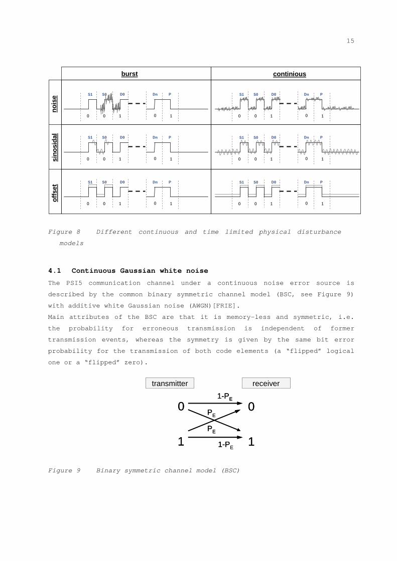
4 Bit error models
Coming from a physical point of view, different disturbance characteristics
can be distinguished. They are basically defined as (time) continuous
distortions and burst errors (limited in their duration). Figure 8 shows the
different error models that are considered with respect to environmental
random hardware faults. For the noise disturbance multiple parallel noise
signals are assumed with normally distributed disturbance levels (Gaussian
white noise). In chapter 4.1 the basic continuous noise model is described
while in chapter 4.2 and 4.3 different models for noise bursts are
discussed. For sinusoidal disturbances (e.g. radio or mobile phone
frequencies) section 4.4 describes a model and its solution. Offset errors
might result from hardware errors or within a specific system set up as
parasitic effect (e.g. voltage drops). However, no separate discussion of
offset disturbances is needed as all offset disturbances will safely lead to
a Manchester error. For avoidance of offset failure mode, hardware measures
(i.e. offset control at the receiver) can additionally be used to improve
the availability of the interface.
15
0 10 0 1
S1 S0 PDnD0
0 10 0 1
S1 S0 PDnD0
0 10 0 1
S1 S0 PDnD0
0 10 0 1
S1 S0 PDnD0
nois
eof
fset
continious
0 10 0 1
S1 S0 PDnD0
0 10 0 1
S1 S0 PDnD0
sino
sida
l
burst
Figure 8 Different continuous and time limited physical disturbance
models
4.1 Continuous Gaussian white noise
The PSI5 communication channel under a continuous noise error source is
described by the common binary symmetric channel model (BSC, see Figure 9)
with additive white Gaussian noise (AWGN)[FRIE].
Main attributes of the BSC are that it is memory-less and symmetric, i.e.
the probability for erroneous transmission is independent of former
transmission events, whereas the symmetry is given by the same bit error
probability for the transmission of both code elements (a “flipped” logical
one or a “flipped” zero).
Figure 9 Binary symmetric channel model (BSC)
0
1
0
1
transmitter receiver
PE
PE
1-PE
1-PE
0
1
0
1
transmitter receiver
PE
PE
1-PE
1-PE
16
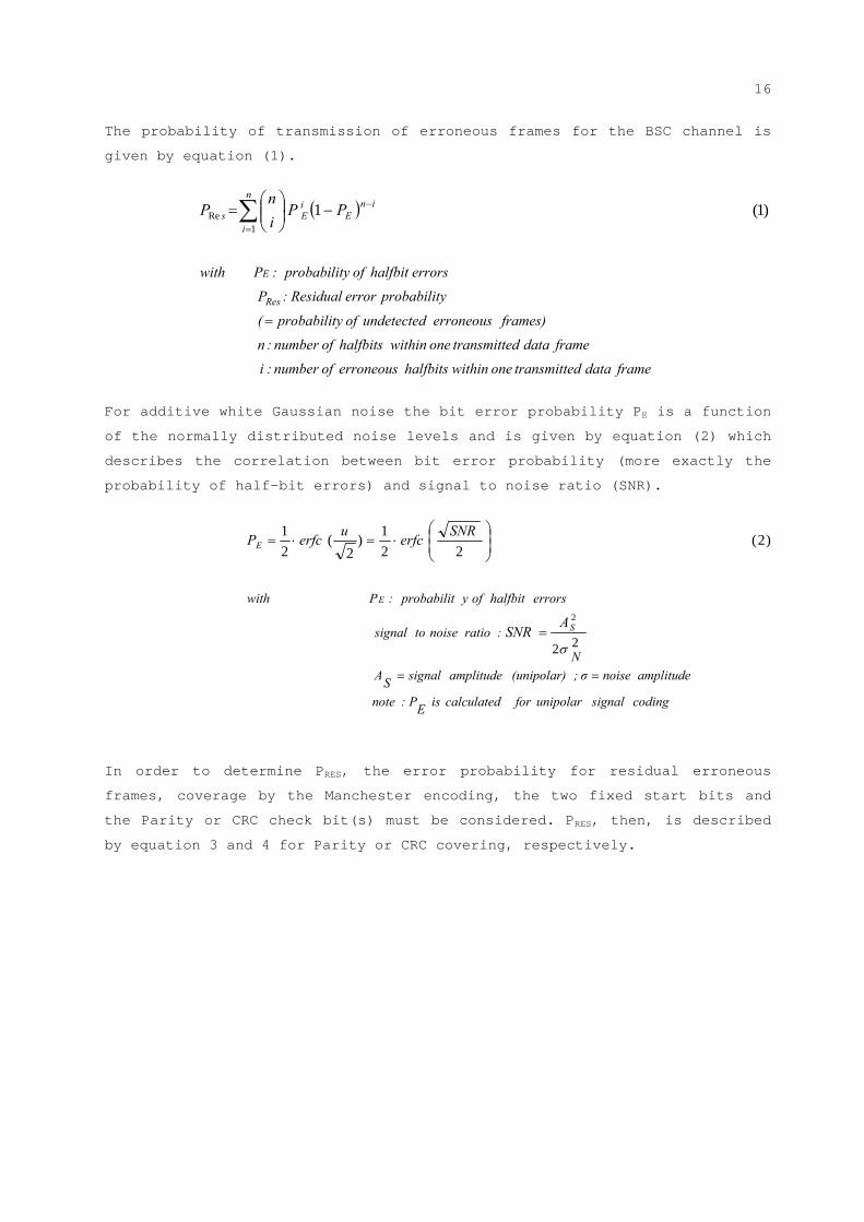
The probability of transmission of erroneous frames for the BSC channel is
given by equation (1).
frame data dtransmitte one withinhalfbits erroneous of number :i
frame data dtransmitte one withinhalfbits of number : n
frames) erroneous undetected ofy probabilit (
y probabilit error Residual:P
errors halfbit ofy probabilit :Pwith
Res
E
n
i
inE
iEs PP
i
nP
)1(1
1Re
For additive white Gaussian noise the bit error probability PE is a function
of the normally distributed noise levels and is given by equation (2) which
describes the correlation between bit error probability (more exactly the
probability of half-bit errors) and signal to noise ratio (SNR).
In order to determine PRES, the error probability for residual erroneous
frames, coverage by the Manchester encoding, the two fixed start bits and
the Parity or CRC check bit(s) must be considered. PRES, then, is described
by equation 3 and 4 for Parity or CRC covering, respectively.
coding signalunipolar for calculatedisE
P :note
amplitude noiseσ ;(unipolar) amplitude signalS
A
N
:ratio noise to signal
errors halfbit ofy probabilit :Pwith
S
E
E
ASNR
SNRerfc
uerfcP
22
2
)2(22
1)2
(21
17
CRCby detected not errors bit x"" of percentage :x)CRC
frame data dtransmitte one withinhalfbits erroneous of number :i
frame data dtransmitte one withinhalfbits of number : n
frames) erroneous undetected ofy probabilit (
y probabilit error Residual:P
errors halfbit ofy probabilit :Pwith
Res
E
n
i
inE
iEs
n
i
inE
iEs
iCRCPP
i
n
P
PPi
n
P
(
)4(2
1
2
22
)3(1
2
22
4
,...8,6,4Re
4
,...12,8,4Re
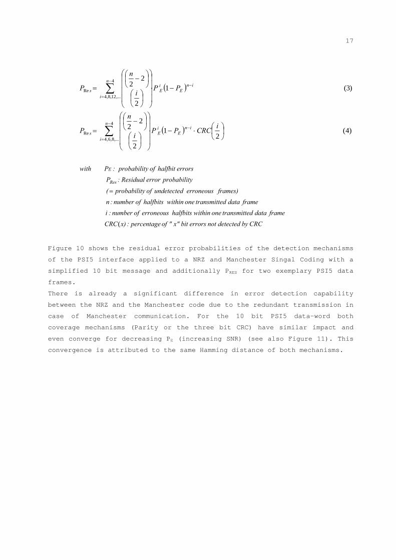
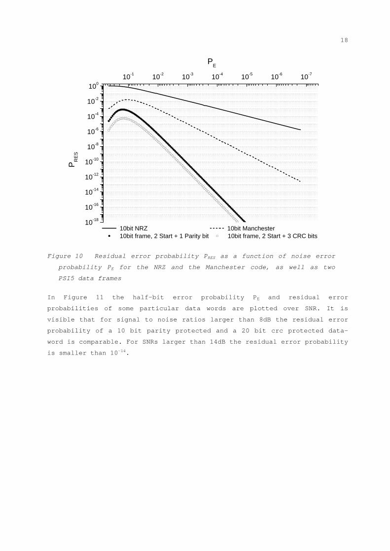
Figure 10 shows the residual error probabilities of the detection mechanisms
of the PSI5 interface applied to a NRZ and Manchester Singal Coding with a
simplified 10 bit message and additionally PRES for two exemplary PSI5 data
frames.
There is already a significant difference in error detection capability
between the NRZ and the Manchester code due to the redundant transmission in
case of Manchester communication. For the 10 bit PSI5 data-word both
coverage mechanisms (Parity or the three bit CRC) have similar impact and
even converge for decreasing PE (increasing SNR) (see also Figure 11). This
convergence is attributed to the same Hamming distance of both mechanisms.
18
10-18
10-16
10-14
10-12
10-10
10-8
10-6
10-4
10-2
10010-1 10-2 10-3 10-4 10-5 10-6 10-7
10bit NRZ 10bit Manchester 10bit frame, 2 Start + 1 Parity bit 10bit frame, 2 Start + 3 CRC bits
PE
PR
ES
Figure 10 Residual error probability PRES as a function of noise error
probability PE for the NRZ and the Manchester code, as well as two
PSI5 data frames
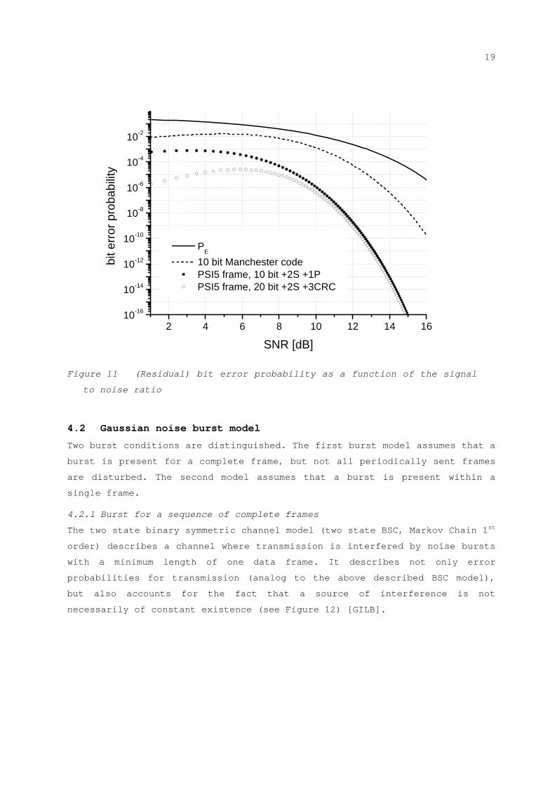
In Figure 11 the half-bit error probability PE and residual error
probabilities of some particular data words are plotted over SNR. It is
visible that for signal to noise ratios larger than 8dB the residual error
probability of a 10 bit parity protected and a 20 bit crc protected data-
word is comparable. For SNRs larger than 14dB the residual error probability
is smaller than 10-14.
19
2 4 6 8 10 12 14 1610-16
10-14
10-12
10-10
10-8
10-6
10-4
10-2
PE
10 bit Manchester code PSI5 frame, 10 bit +2S +1P PSI5 frame, 20 bit +2S +3CRC
bit e
rror
pro
babi
lity
SNR [dB]
Figure 11 (Residual) bit error probability as a function of the signal
to noise ratio
4.2 Gaussian noise burst model
Two burst conditions are distinguished. The first burst model assumes that a
burst is present for a complete frame, but not all periodically sent frames
are disturbed. The second model assumes that a burst is present within a
single frame.
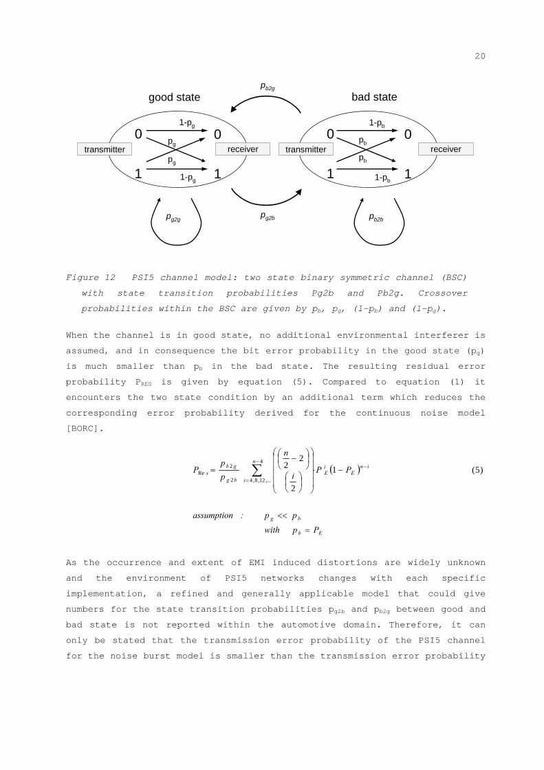
4.2.1 Burst for a sequence of complete frames
The two state binary symmetric channel model (two state BSC, Markov Chain 1st
order) describes a channel where transmission is interfered by noise bursts
with a minimum length of one data frame. It describes not only error
probabilities for transmission (analog to the above described BSC model),
but also accounts for the fact that a source of interference is not
necessarily of constant existence (see Figure 12) [GILB].
20
0
1
0
1
good state bad state
0
1
0
1
transmitter receiverpg
pg
1-pg
1-pg
pb
pb
1-pb
1-pb
pg2b
pb2g
pg2g pb2b
transmitter receiver
Figure 12 PSI5 channel model: two state binary symmetric channel (BSC)
with state transition probabilities Pg2b and Pb2g. Crossover
probabilities within the BSC are given by pb, pg, (1-pb) and (1-pg).
When the channel is in good state, no additional environmental interferer is
assumed, and in consequence the bit error probability in the good state (pg)
is much smaller than pb in the bad state. The resulting residual error
probability PRES is given by equation (5). Compared to equation (1) it
encounters the two state condition by an additional term which reduces the
corresponding error probability derived for the continuous noise model
[BORC].
As the occurrence and extent of EMI induced distortions are widely unknown
and the environment of PSI5 networks changes with each specific
implementation, a refined and generally applicable model that could give
numbers for the state transition probabilities pg2b and pb2g between good and
bad state is not reported within the automotive domain. Therefore, it can
only be stated that the transmission error probability of the PSI5 channel
for the noise burst model is smaller than the transmission error probability
Eb
bg
n
i
inE
iE
bg
gbs
Ppwith
pp:assumption
PPi
n
p
pP
)5(1
2
224
,...12,8,42
2Re
21
of the continuous noise model, minimized by the factor bg
gb
p
p
2
2. A range of 10-3
has been assumed in that context for the CAN interface. [UNRU]
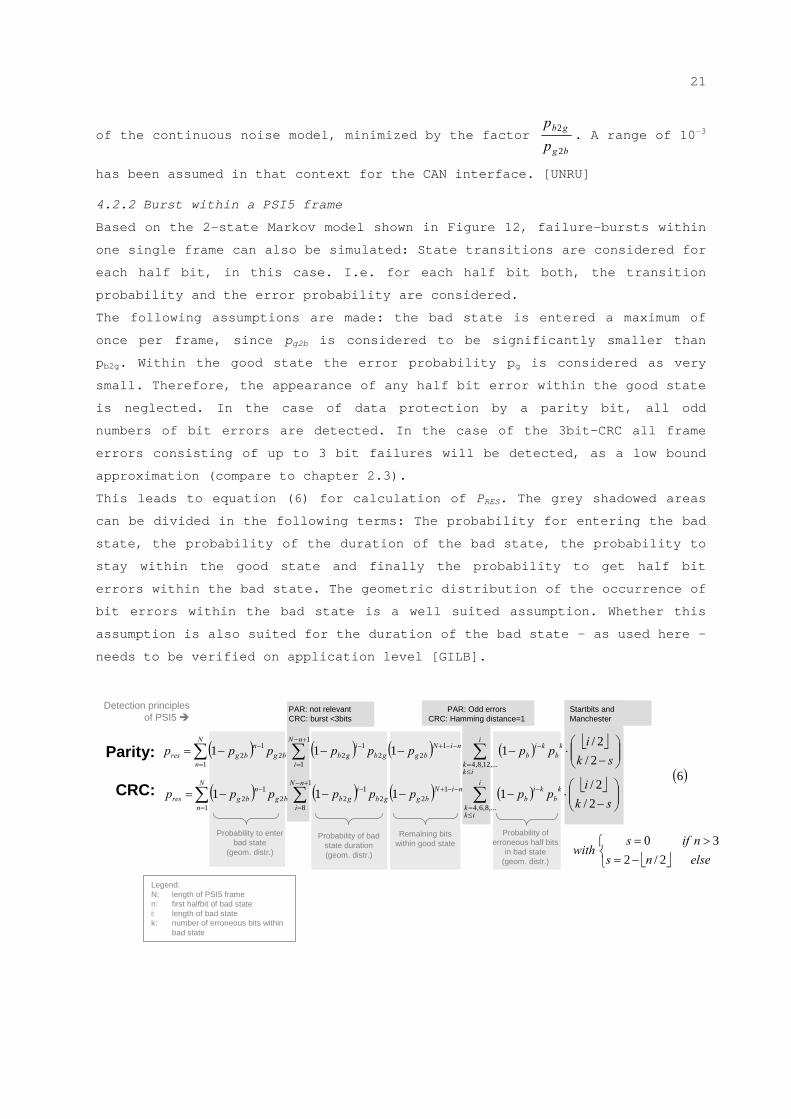
4.2.2 Burst within a PSI5 frame
Based on the 2-state Markov model shown in Figure 12, failure-bursts within
one single frame can also be simulated: State transitions are considered for
each half bit, in this case. I.e. for each half bit both, the transition
probability and the error probability are considered.
The following assumptions are made: the bad state is entered a maximum of
once per frame, since pg2b is considered to be significantly smaller than
pb2g. Within the good state the error probability pg is considered as very
small. Therefore, the appearance of any half bit error within the good state
is neglected. In the case of data protection by a parity bit, all odd
numbers of bit errors are detected. In the case of the 3bit-CRC all frame
errors consisting of up to 3 bit failures will be detected, as a low bound
approximation (compare to chapter 2.3).
This leads to equation (6) for calculation of PRES. The grey shadowed areas
can be divided in the following terms: The probability for entering the bad
state, the probability of the duration of the bad state, the probability to
stay within the good state and finally the probability to get half bit
errors within the bad state. The geometric distribution of the occurrence of
bit errors within the bad state is a well suited assumption. Whether this
assumption is also suited for the duration of the bad state – as used here -
needs to be verified on application level [GILB].
Startbits and Manchester
Probability to enter bad state
(geom. distr.)
Probability of bad state duration(geom. distr.)
Probability of erroneous half bits
in bad state(geom. distr.)
PAR: not relevantCRC: burst <3bits
PAR: Odd errorsCRC: Hamming distance=1
Legend:N: length of PSI5 framen: first halfbit of bad statei: length of bad statek: number of erroneous bits within
bad state
Parity:
CRC:
Remaining bits within good state
Detection principles of PSI5
6
2/2/
1111
2/2/
1111
1
1
8 ,...8,6,4
122
122
12
1
1
1 ,...12,8,4
122
122
12
N
n
nN
i
i
ikk
kb
kib
niNbggb
igbbg
nbgres
N
n
nN
i
i
ikk
kb
kib
niNbggb
igbbg
nbgres
sk
ipppppppp
sk
ipppppppp
elsens
nifswith
2/230
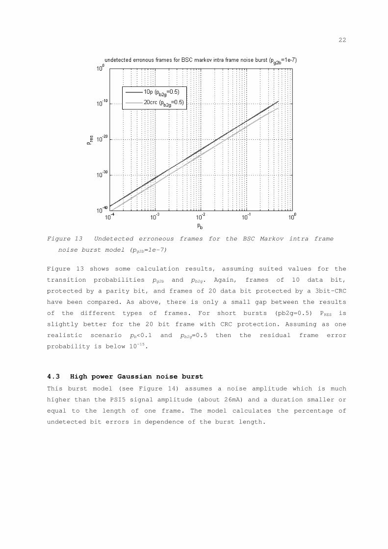
22
Figure 13 Undetected erroneous frames for the BSC Markov intra frame
noise burst model (pg2b=1e-7)
Figure 13 shows some calculation results, assuming suited values for the
transition probabilities pg2b and pb2g. Again, frames of 10 data bit,
protected by a parity bit, and frames of 20 data bit protected by a 3bit-CRC
have been compared. As above, there is only a small gap between the results
of the different types of frames. For short bursts (pb2g=0.5) PRES is
slightly better for the 20 bit frame with CRC protection. Assuming as one
realistic scenario pb<0.1 and pb2g=0.5 then the residual frame error
probability is below 10-15.
4.3 High power Gaussian noise burst
This burst model (see Figure 14) assumes a noise amplitude which is much
higher than the PSI5 signal amplitude (about 26mA) and a duration smaller or
equal to the length of one frame. The model calculates the percentage of
undetected bit errors in dependence of the burst length.

23
0 10 0 1
S1 S0 PDnD0
ABURST
APSI5
TBURST
Figure 14 Model of a high power Gaussian noise burst within a PSI5
frame
With this assumption, the probability that a half bit exposed to the noise
burst is flipped, is 50% and 50% to stay at its old value. The possible
consequences have been calculated for different noise burst lengths assuming
a simple two sample point receiver model. However, synchronization problems,
which would improve the detection capability because wrong frame lengths
would be detected, are excluded from the following considerations.
In a first step the probability of a bit error without Manchester error
(both half bits flipped) is calculated. If the burst length is smaller than
a full bit, there will be at 50% no effect and at 50% a Manchester error. If
the length is as long as a full bit, there are 3 possibilities: at 25%
chance no error since the noise burst does not alter both half bits. At 25%
there is a bit flip because the noise burst alters both half bits. And at
50% chance there is a Manchester error since the noise burst alters either
the first or the second half bit. This calculation can be continued for
longer noise bursts in the same way.
From the resulting bit error probability without Manchester error, the
probability for undetected bit errors can be calculated very easily for the
parity protection. All odd number of bit errors will be detected by the
parity check. All even numbers of bit errors will be undetected.
The PSI5 CRC has a hamming distance of two having the same effect as the
parity check. Additionally, the bit error burst detection capabilities as
described in chapter 2.3 are used. The result is shown in Figure 15 giving
the percentage of undetected errors over the length of the noise burst given
in units of the length of full bits.
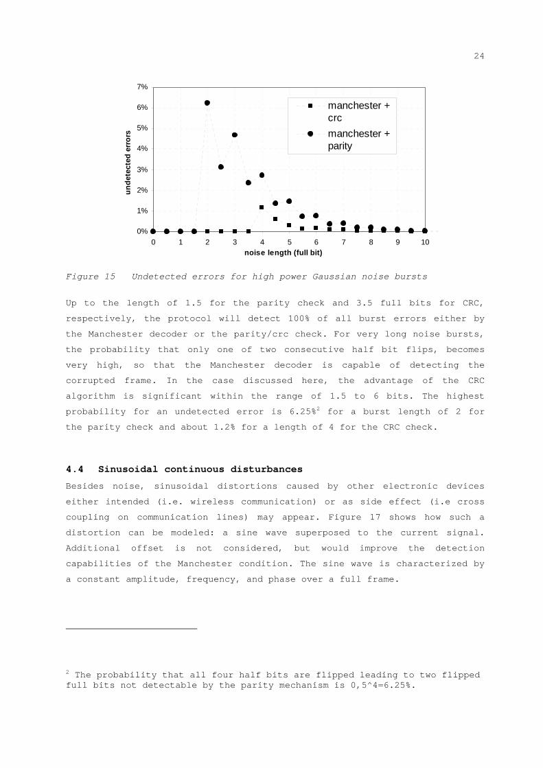
24
0%
1%
2%
3%
4%
5%
6%
7%
0 1 2 3 4 5 6 7 8 9 10
noise length (full bit)
unde
tect
ed e
rror
s
manchester +crc
manchester +parity
Figure 15 Undetected errors for high power Gaussian noise bursts
Up to the length of 1.5 for the parity check and 3.5 full bits for CRC,
respectively, the protocol will detect 100% of all burst errors either by
the Manchester decoder or the parity/crc check. For very long noise bursts,
the probability that only one of two consecutive half bit flips, becomes
very high, so that the Manchester decoder is capable of detecting the
corrupted frame. In the case discussed here, the advantage of the CRC
algorithm is significant within the range of 1.5 to 6 bits. The highest
probability for an undetected error is 6.25%2 for a burst length of 2 for
the parity check and about 1.2% for a length of 4 for the CRC check.
4.4 Sinusoidal continuous disturbances
Besides noise, sinusoidal distortions caused by other electronic devices
either intended (i.e. wireless communication) or as side effect (i.e cross
coupling on communication lines) may appear. Figure 17 shows how such a
distortion can be modeled: a sine wave superposed to the current signal.
Additional offset is not considered, but would improve the detection
capabilities of the Manchester condition. The sine wave is characterized by
a constant amplitude, frequency, and phase over a full frame.
2 The probability that all four half bits are flipped leading to two flipped full bits not detectable by the parity mechanism is 0,5^4=6.25%.

25
Figure 16 Sinusoidal disturbance model for a PSI5 frame
Averaging over all phases and data words the residual frame error
probability can be calculated as a function of amplitude A and frequency f
PRES(A,f). As before, a simple receiver model with oversampling factor 2 (one
sample per half bit) is assumed.
Figure 17 shows the results, again for a 10 bit frame with parity protection
and a frame of 20 data bits and 3bit-CRC. The x-axis represents the relative
frequency, the y-axis the relative amplitude. Here, APSI5 is half of the
delta between high and low current signal levels, i.e. the distance signal
level to detection threshold. The percentage of residual frame errors PRES is
given by the intensity of grey out areas. Most frequency ranges are covered
by the Manchester decoder, i.e. the Manchester condition is not fulfilled
and frame/bit errors are detected. Undetected frame errors are most probable
for odd multiples of the PSI5 frequency and only when the amplitude of the
sinusoidal distortion exceeds APSI5.
Figure 17 Probability of undetected bit errors in dependence of
distortion frequency and amplitude for parity and CRC protection

26
This calculation model does not consider the gap between single frames. By
suited measures at the receiver (e.g. by a check for data within the frame
gap or by bit-counting), undetected failures due to sinusoidal distortions
which start before, or last longer than, a PSI5 frame can be avoided. Hence,
all distortions which last longer than one frame might be detected
significantly better.
In case of sine wave distortions with amplitudes below APSI5 the continuous
noise distortion models can be used for calculation of PE / PRES by adopting
the SNR accordingly (compare chapter 6.2). Higher distortions are considered
unlikely due to the robust current modulation. Nevertheless, such
distortions should be avoided. For very high frequencies, the input stage of
a receiver represents a low pass filter (e.g. anti-aliasing filter)
suppressing the high frequencies making the interface even more robust to
high frequency distortions. The cut off frequency depends on the actual
design.
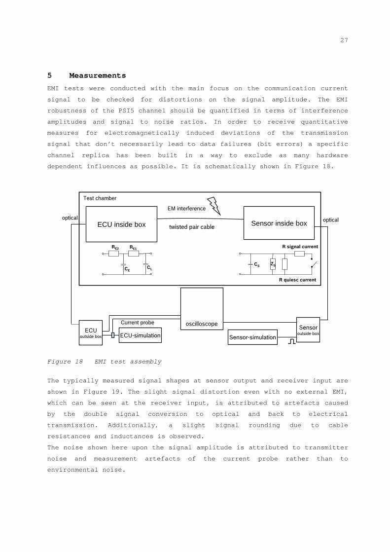
27
5 Measurements
EMI tests were conducted with the main focus on the communication current
signal to be checked for distortions on the signal amplitude. The EMI
robustness of the PSI5 channel should be quantified in terms of interference
amplitudes and signal to noise ratios. In order to receive quantitative
measures for electromagnetically induced deviations of the transmission
signal that don’t necessarily lead to data failures (bit errors) a specific
channel replica has been built in a way to exclude as many hardware
dependent influences as possible. It is schematically shown in Figure 18.
Figure 18 EMI test assembly
The typically measured signal shapes at sensor output and receiver input are
shown in Figure 19. The slight signal distortion even with no external EMI,
which can be seen at the receiver input, is attributed to artefacts caused
by the double signal conversion to optical and back to electrical
transmission. Additionally, a slight signal rounding due to cable
resistances and inductances is observed.
The noise shown here upon the signal amplitude is attributed to transmitter
noise and measurement artefacts of the current probe rather than to
environmental noise.
twisted pair cable
CLCE
RE1 R signal current
ECUoutside box ECU-simulation Sensor-simulation
Current probe
optical optical
Test chamber
EM interference
oscilloscopeSensor
outside box
RE2
R quiesc current
ZSCS
ECU inside box Sensor inside box
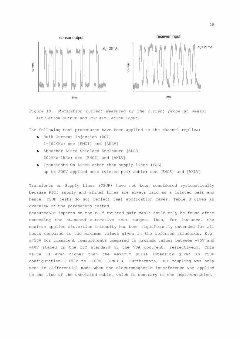
28
sensor output
IS= 25mA
time
cu
rren
t
time
curr
ent
IS= 21mA
receiver input
Figure 19 Modulation current measured by the current probe at sensor
simulation output and ECU simulation input.
The following test procedures have been applied to the channel replica:
Bulk Current Injection (BCI)
1-400MHz; see [EMC1] and [AKLV]
Absorber Lined Shielded Enclosure (ALSE)
200MHz-1kHz; see [EMC2] and [AKLV]
Transients On Lines other than supply lines (TOL)
up to 200V applied onto twisted pair cable; see [EMC3] and [AKLV]
Transients on Supply Lines (TSUP) have not been considered systematically
because PSI5 supply and signal lines are always laid as a twisted pair and
hence, TSUP tests do not reflect real application cases. Table 3 gives an
overview of the parameters tested.
Measureable impacts on the PSI5 twisted pair cable could only be found after
exceeding the standard automotive test ranges. Thus, for instance, the
maximum applied distortion intensity has been significantly extended for all
tests compared to the maximum values given in the referred standards. E.g.
±750V for transient measurements compared to maximum values between -75V and
+40V stated in the ISO standard or the VDA document, respectively. This
value is even higher than the maximum pulse intensity given in TSUP
configuration (-150V to -100V, [EMC4]). Furthermore, BCI coupling was only
seen in differential mode when the electromagnetic interference was applied
to one line of the untwisted cable, which is contrary to the implementation.
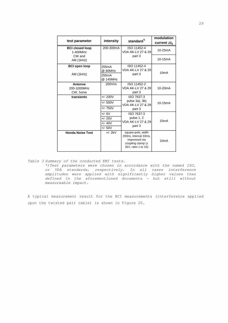
29
test parameter intensity standard*)
255mA@ 80MHz
255mA@ 145MHz
+/- 200V
+/- 500V
+/- 750V
+/- 6V
+/- 20V
+/- 40V
+/- 50V
ISO 11452-4VDA AK-LV 27 & 29
part 3
Antenne200-1000MHz
CW, ho/ve10-20mA
transients
200V/m
BCI closed loop1-400MHzCW and
AM (1kHz)
200-300mA
ISO 7637-3pulse 1, 2
VDA AK-LV 27 & 29 part 3
Honda Noise Test square-puls, width 200ns, interval 33ms,
impressed via coupling clamp (± 2kV, ratio 1 to 10)
ISO 11452-2VDA AK-LV 27 & 29
part 3
10-15mA
15mA
ISO 7637-3pulse 3a), 3b)
VDA AK-LV 27 & 29 part 3
BCI open loop
AM (1kHz)
ISO 11452-4VDA AK-LV 27 & 29
part 3
modulation current IS
10mA
+/- 2kV
10mA
10-25mA
10-15mA
Table 3 Summary of the conducted EMI tests.
*)Test parameters were chosen in accordance with the named ISO, or VDA standards, respectively. In all cases interference amplitudes were applied with significantly higher values than defined in the aforementioned documents - but still without measureable impact.
A typical measurement result for the BCI measurements (interference applied
upon the twisted pair cable) is shown in Figure 20.
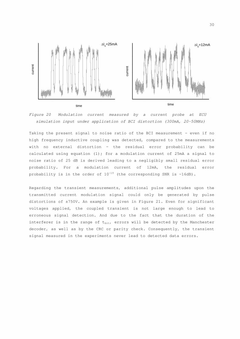
30
IS=12mA
curr
ent
time
IS=25mA
time
curr
ent
Figure 20 Modulation current measured by a current probe at ECU
simulation input under application of BCI distortion (300mA, 20-50MHz)
Taking the present signal to noise ratio of the BCI measurement - even if no
high frequency inductive coupling was detected, compared to the measurements
with no external distortion – the residual error probability can be
calculated using equation (1); for a modulation current of 25mA a signal to
noise ratio of 25 dB is derived leading to a negligibly small residual error
probability. For a modulation current of 12mA, the residual error
probability is in the order of 10-19 (the corresponding SNR is ~16dB).
Regarding the transient measurements, additional pulse amplitudes upon the
transmitted current modulation signal could only be generated by pulse
distortions of ±750V. An example is given in Figure 21. Even for significant
voltages applied, the coupled transient is not large enough to lead to
erroneous signal detection. And due to the fact that the duration of the
interferer is in the range of tbit, errors will be detected by the Manchester
decoder, as well as by the CRC or parity check. Consequently, the transient
signal measured in the experiments never lead to detected data errors.
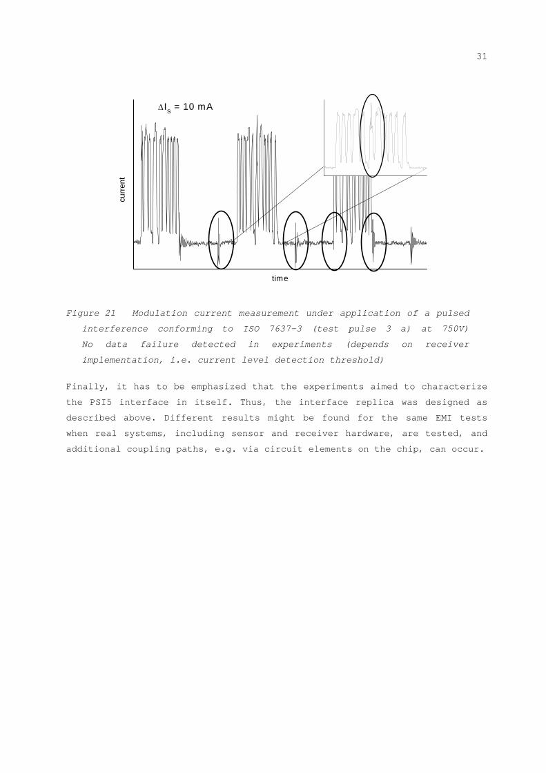
31
curr
ent
time
IS = 10 mA
Figure 21 Modulation current measurement under application of a pulsed
interference conforming to ISO 7637-3 (test pulse 3 a) at 750V)
No data failure detected in experiments (depends on receiver
implementation, i.e. current level detection threshold)
Finally, it has to be emphasized that the experiments aimed to characterize
the PSI5 interface in itself. Thus, the interface replica was designed as
described above. Different results might be found for the same EMI tests
when real systems, including sensor and receiver hardware, are tested, and
additional coupling paths, e.g. via circuit elements on the chip, can occur.
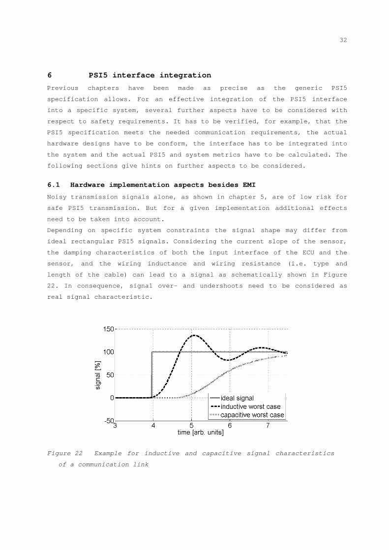
32
6 PSI5 interface integration
Previous chapters have been made as precise as the generic PSI5
specification allows. For an effective integration of the PSI5 interface
into a specific system, several further aspects have to be considered with
respect to safety requirements. It has to be verified, for example, that the
PSI5 specification meets the needed communication requirements, the actual
hardware designs have to be conform, the interface has to be integrated into
the system and the actual PSI5 and system metrics have to be calculated. The
following sections give hints on further aspects to be considered.
6.1 Hardware implementation aspects besides EMI
Noisy transmission signals alone, as shown in chapter 5, are of low risk for
safe PSI5 transmission. But for a given implementation additional effects
need to be taken into account.
Depending on specific system constraints the signal shape may differ from
ideal rectangular PSI5 signals. Considering the current slope of the sensor,
the damping characteristics of both the input interface of the ECU and the
sensor, and the wiring inductance and wiring resistance (i.e. type and
length of the cable) can lead to a signal as schematically shown in Figure
22. In consequence, signal over- and undershoots need to be considered as
real signal characteristic.
Figure 22 Example for inductive and capacitive signal characteristics
of a communication link

33
Ripples on the supply voltage can also cause a current ripple depending on
the input interface circuit, the signal may also be distorted due to
coupling from other PSI5 channels and finally tolerances of the detection
threshold need to be regarded.
All these implementation aspects can be considered for SNR calculation
according to the following equation (7):
)7(2
' 222 impleff
eff
s withaA
SNR
For any effect which reduces the signal distance, we can reduce the signal
level AS by an implementation dependent amplitude a. Considering additional
impacts on signal level that can be modeled as noise with approximately
Gaussian distribution, the standard deviation can be adopted to an
effective noise level eff by adding an implementation specific noise term
impl.
6.2 Calculating residual error rates for an actual system
This chapter will give an example approach to calculate the bit error rate
for an implemented system that is exposed to continuous Gaussian noise (see
chaper 4.1). Implementation aspects considered are: the nominal quiescent
and signal current levels, possible signal ripples, over- and undershoots
within the individual system, the tolerance range of the detection threshold
and potential coupling of other signals. The reduced SNR level (increased
noise / reduced distance of relevant signal levels for calculating the error
probability) is included in the calculation of the half-bit error
probability pE according to equation (2).
We consider a typical airbag application (two start, 10 data bits, one
parity bit and at least one stop bit): the nominal distance between
quiescent and signal current level is 26mA, the minimum value is 22mA.
Typical noise shows a standard deviation below 1mA. For the exemplary
implementation case, the SNR is adapted by reducing the delta current by
10mA and increasing the noise standard deviation up to 1.5mA. Based on the
so calculated half-bit error probability of PE=3.10-5 the residual frame
error rate PRES after Manchester decoding and parity check, is below 10-16.
With 2 kHz data rate, and the assumption that a single corrupted undetected
frame violates the safety goal on system level, A residual failure rate <10-
10 of undetected failures per hour is derived.

34
More intelligent receiver designs, which do not just use two point sampling,
will render the values even better. For most systems a single frame error
will not be safety critical. When assuming that at least two (consecutive)
corrupted frames have to remain undetected, the residual failure rate for
above example drops to below 10-20/h which seems to be out of scope to be
considered.
Following the above considerations, which is considered as worst case
example, the PSI5 interface will not be the safety critical element within
an ASIL D system. However, the confirmation has to be made on a system level
since there may be other faults (hardware faults of all parts of the system)
which additionally contribute to the safety metric target.
6.3 ISO26262 conformal calculation of relative metrics
The ISO26262 requires the consideration of an absolute failure metric
(Probabilistic metric for random Hardware Failures (PMHF)) and two relative
metrics (Single-point fault metric (SPFM) and latent-point fault
metric (LPFM)). The PMHF can be calculated using the failure rate of the
PSI5 interface as exemplary shown in chapter 6.2.
The SPFM for the safety goal is specified as the quotient of all undetected
single faults and all faults at all. According to equation C.5 in Part 5 of
the ISO26262 and applying the calculation example of chapter 6.2 the
following result is achieved: The overall failure rate of the PSI5 interface
is very high (i.e ~PSI5=2.2•10+2/h for PE=3•10-5 with 2kHz sampling) compared
to other hardware elements (typically much below 1.10-8/h) But the residual
failure rate (res,PSI5=10-10/h), again, is comparable to other hardware
elements. Thus, the SPFM of the system would be misleadingly determined by
the PSI5 failure rate. Due to this effect, inclusion of the PSI5 interface
in the relative SPFM should be avoided.
The LPFM is the second relative metric which shall be considered according
to the ISO26262. An example for a latent fault within the PSI5 interface
would be a wrong quiescent current. If this current drops below the
specification, the system might still work correctly, however, the SNR ratio
drops significantly resulting in a degraded EMI robustness. Such failures
should be included within the considerations of systematic faults of the
hardware elements (which are application specific) and the calculation of
their LPFM.
Hence, it is adequate to include the PSI5 interface in the absolute metrics
but not in the relative ones. However, it might explain the following
statement of the ISO26262: “These quantitative target […] do not have any

35
absolute significance and are only useful to compare a new design with
existing ones”.
7 Summary and Conclusions
Within this paper the application of the ISO26262 to the new PSI5
specification 2.0 is discussed with a practical background considering
systematic and random faults.
PSI5 provides many means for systematic error avoidance and detection, both
on physical and on data link layer. The considerations have shown evidence
that all systematic effects can be well handled by the PSI5 interface.
For conformity considerations regarding the ISO26262, the probability of
undetected random hardware failures needs to be assessed. Within this paper
the probability of undetected environmental random faults is emphasized and
several models to calculate the residual frame error probability have been
presented. Furthermore, offset failures are uncritical due the Manchester
condition, as well as sinusoidal disturbances are uncritical up to a certain
disturbance level.
Measurements have been conducted and the results were used to parameterize
the theoretical models to real world environments. However, these
experiments show that the effects of “real world disturbances” upon the PSI5
line (as reproduced by the applied test procedures) are so small that all
applied models are in a range where practically no errors are present. In
other words, there are no disturbances to be detected due to the robust
interface.
Regarding new, low current operation modes as optionally specified for the
power train substandard, the definition of the current levels plus
constraints regarding the implementation (e.g. tolerance with respect to the
detection threshold, maximum signal ripple, etc.) will mainly define the
values PE and PRES. Referring to the measurement results of chapter 5, the
lower signal levels itself still make individual safety applications
conceivable, but need to be investigated thoroughly with respect to their
effective implementation and resulting constraints.
Summing up, all aspects suggested by the ISO26262 have been analysed and
several methods were presented to handle the possible faults. The
application standard protocol definitions seem to be well suited for their
intended applications.
Overall, the presented methods support conformity considerations regarding
ISO26262 for systems rated up to ASIL D. However, the final judgment on

36
functional safety of a system is always subject to an application and
implementation specific safety analysis and can only be done on system
level.

37
8 Acknowledgments
This paper concludes the results of the PSI5 working group “Functional
safety” which met on several occasions from 2010 to 2011. As well as from
the above named authors, valuable contributions to this work were made by
members of several associated companies of the PSI5 consortium, in
particular Autoliv, Continental, Freescale, IHR, Infineon, TRW, Bosch.
38
References
[OHL] ch. Ohl, T. Weiss, R. Gschwind-Schilling, PSI5:
Sensorschnittstellen für universells Anwendungen, „Sensoren im
Automobil II“, 2007
[PSI5] Peripheral Sensor Interface for Automotive Applications,
Technical Specification V2.0, 01.06.2011
[REIM] M. Reiman et al., PSI5 Interface for Ultra Compact Inertial
Sensor Cluster, Advanced Microsystems for Automotive
Applications of Smart Systems for Electric, Safe and Networked
Mobility 2011, Editors: G. Meyer, J. Valldorf
[BOCK] J. Bock, Weiterentwicklung des PSI5 Sensorbus für
Applikationen im Bereich Powertrain und Chassis, 31. Tagung
"Elektronik im Kraftfahrzeug", Haus der Technik, Essen, 08.-
09.11.2011
[ISO] Road Vehicles – Functional safety, Final Draft International
Standard ISO/TC 22/SC 3 BL18 Date: 2010-11-20 ISO/FDIS 26262-
3:2010(E) ISO/TC 22/SC 3/WG 16
[FRIE] B. Friedrichs, Kanalcodierung – Grundlagen und Anwendungen in
modernen Kommunikationssystemen, Springer Verlag, Berlin,
1996, ISBN/EAN 3540593535
[PSI5web] http://www.psi5.org [accessed 02.02.2012]
[SENT] Single Edge Nibble Transmission for Automotive Applications,
SAE J2716, Jan. 2010.
[DSI] DSI3 Bus Standard, Rev. 1.0, Denso Corporation, Freescale
Semiconductor Inc. and TRW Automotive Inc., 16.02.2011
[CAN] CAN Specification 2.0, Robert Bosch GmbH, 1991
[FLEX] FlexRay Communication Systems, Protocol Specification Version
2.0, FlexRay Consortium 30.06.2004
[GILB] E.N. Gilbert, Capacity of a Burst-Noise Channel, Bell System
Technical Journal, Vol. 39, pp. 1253-1265, 1960
[BORC] J. Börcsök, H.-T. Hannan, Determination of Bit Error and
Residual Error Rates for Safety Critical Communication, Second
International Conference on Systems, IEEE Computer Society,
2007
39
[UNRU] J. Unruh, H.-J. Mathony, K.-H. Kaiser, Error Detection
Analysis of Automotive Communication Protocols, SAE paper
900699, 1990
[EMC1] International Standard ISO 11452-4, Bulk Current Injection
(BCI), 01.04.2005
[AKLV] AK-LV 27 / AK-LV 29, Teil 3, EMV-Anforderungen, V2.06,
09.03.2010, VDA Arbeitskreis Sicherheitselektronik
[EMC2] International Standard ISO 11452-2, Absorber-Lined Shielded
Enclosure, 01.11.2004
[EMC3] International Standard ISO 7637-3, Electrical Transient
Transmission By Capacitive And Inductive Coupling Via Lines
Other Than Supply Lines, 01.07.2007
[EMC4] International Standard ISO 7637-2, Electrical transient
conduction along supply lines only, 2004