Embed Size (px)
Citation preview
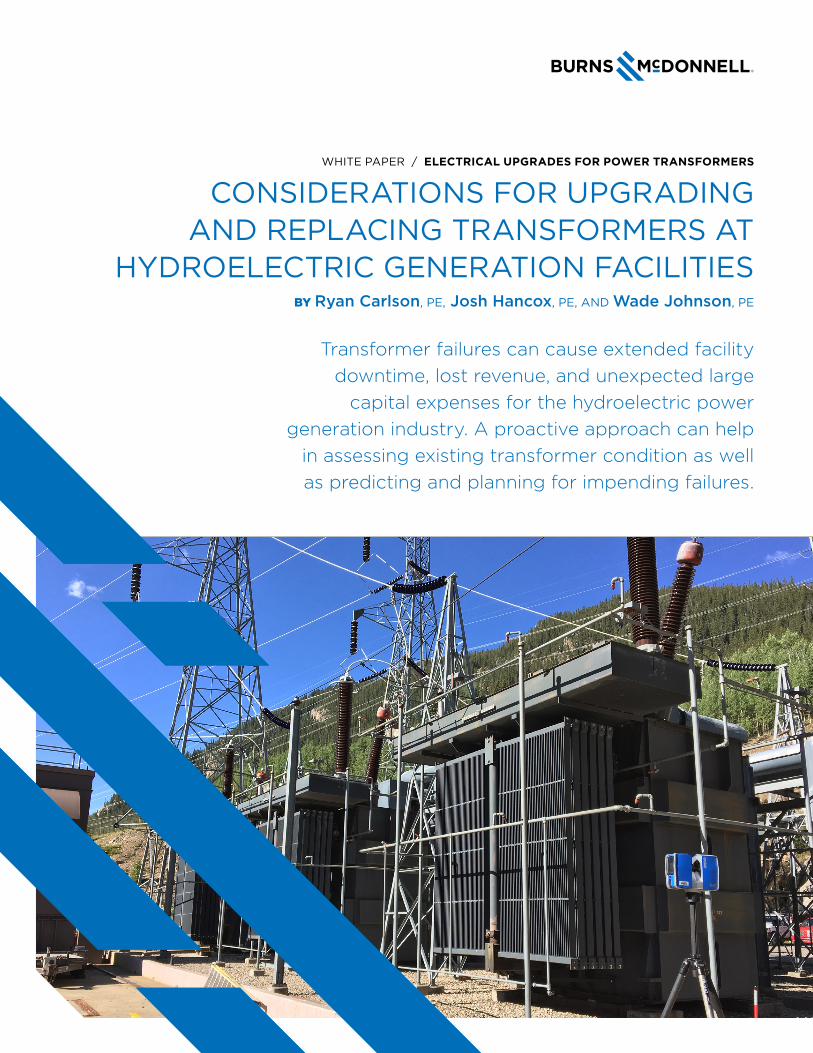
WHITE PAPER / ELECTRICAL UPGRADES FOR POWER TRANSFORMERS
CONSIDERATIONS FOR UPGRADING AND REPLACING TRANSFORMERS AT
HYDROELECTRIC GENERATION FACILITIESBY Ryan Carlson, PE, Josh Hancox, PE, AND Wade Johnson, PE
Transformer failures can cause extended facility downtime, lost revenue, and unexpected large
capital expenses for the hydroelectric power generation industry. A proactive approach can help
in assessing existing transformer condition as well as predicting and planning for impending failures.
WHITE PAPER / ELECTRICAL UPGRADES FOR AGING TRANSFORMERS
© 2020 PAGE 2 OF 6
According to the U.S. Energy Information Administration,
the average age of a hydroelectric power generation
facility in the United States is 64 years. With the recent
push to decarbonize the power industry, hydropower
remains an integral part of our energy future. As a
result, many aging hydroelectric facilities will pursue life
extension projects in the coming years, including the
replacement of large generator step-up and unit auxiliary
transformers. This paper outlines the considerations facility
owners should make to monitor existing transformers and
to execute power transformer replacment projects.
Transformers are a critical part of the power generation
infrastructure. The generator step-up transformer converts
the generator voltage to a higher voltage for transmission,
while auxiliary transformers reduce the generator or
transmission system voltage for use by the facility’s
process equipment. These large power transformers
are often made-to-order, and equipment lead times of
12 months or more are fairly common. Failure of any
individual transformer could render a facility unusable for
an extended period while a replacement transformer is
procured and installed. As a result, transformer failures
may lead to significant loss in revenue to hydroelectric
power generation facility owners. Traditionally, one of the
only ways to guard against the severe financial impact of a
transformer failure was to have a spare transformer on-site
and ready for installation should it be needed.
The probability of a transformer failure depends on
many factors. However, in general, if power transformers
operate within their design parameters, the chance of
failure follows a “bathtub curve.” For the first few years
of operation, the chance of failure is higher because of
potential design defects or manufacturing flaws. After a
transformer has been in service for a few years, it enters its
period of most reliable operation with the lowest chance
of failure. Typically, after 30-40 years, the likelihood of
transformer failure rises again as the equipment reaches
the end of its design life. Mitigating risks associated with
transformers reaching the end of their useful service
lives needs to be part of the long-term operation and
maintenance plan of a facility.
CONDITION MONITORING OF EXISTING TRANSFORMERSIdentifying appropriate ways to assess the health and
longevity of transformers is imperative. There are various
means and methods to perform condition monitoring of
transformers. The following is a summary of some key
types, as well as explanation of the benefits and how
various transformer parameters can help in foreseeing and
preventing a failure.
DISSOLVED GAS ANALYSISA dissolved gas analysis (DGA) is an assessment of the
transformer insulating oil used to determine the gas
concentrations within the oil. A particular type of gas
and its concentration can provide early indication of an
imminent transformer failure. While oil samples can be
taken manually and sent to a laboratory for analysis,
transformers can also be retrofitted with modern online
DGA monitors that measure gas composition in real time.
Whether it is electrical insulation paper aging, long time
overloads or internal arcing, most DGA monitors can
trigger an alarm to notify the user of a potential problem,
and some of the advanced models can even report the
constituent gases and respective quantities. It is a best
practice to perform DGA testing of the transformer oil
at regular intervals to understand how the equipment’s
condition is changing over time, as results are most
meaningful when compared to baseline measurements.
ELECTRICAL TESTSElectrical tests including insulation resistance, winding
resistance, turns ratio and other tests that may be
performed when the transformer is deenergized and
properly locked-out and tagged-out, can also provide
valuable diagnostic and condition information. Sweep
Frequency Response Analysis (SFRA) is a recommended
additional test that can provide valuable information about
the internal mechanical condition of the transformer.
As is the case with DGA testing, it is best to perform
electrical tests at regular, although less frequent,
intervals to understand how the condition is changing
over time. Occasionally there are concerns that certain
electrical tests such as insulation resistance may weaken
transformers that are nearing their end of life.
WHITE PAPER / ELECTRICAL UPGRADES FOR AGING TRANSFORMERS
© 2020 PAGE 3 OF 6
ADVANCED WINDING AND OIL TEMPERATURE MONITORINGThe per-unit life of a transformer, per Institute of Electrical
and Electronics Engineers (IEEE) standard C57.91, is a
function of temperature (i.e., loading). Consequently,
most large power transformers have various instruments
(gauges or relays) to show winding temperature
and/or oil temperature, with measurements most
commonly derived from a “hot-spot” current transformer
and a capillary type thermometer or a resistance
temperature detector (RTD) submerged in the transformer
oil. New intelligent monitors, installed locally at the
transformer, can actively monitor this temperature data
to predict life consumption, manage transformer cooling
systems, and transmit temperature information back to
the facility distributed control system (DCS), or other
supervisory control and data acquisition (SCADA) system,
for trending and monitoring. Intelligent monitoring and
automatic cooling systems can reduce the transformer
temperature and prevent premature failure from thermal
overload conditions.
BUSHING AND SURGE ARRESTOR POWER FACTOR, CAPACITANCE AND PARTIAL DISCHARGEFailed bushings and surge arresters are common causes of
catastrophic failure in transformers. Transformer bushings
and arresters undergo power factor testing in the factory
to establish a baseline for insulation health throughout
their lives. Typically, transformers have to be deenergized
and disconnected to perform the required routine
maintenance testing, which can require a facility outage
or, in some cases, local blackout conditions. Alternatively,
transformers can now be equipped with online bushing
power factor and capacitance or partial discharge
monitoring systems to detect insulation degradation over
time and highlight the need for repair prior to failure.
ON-LOAD TAP CHANGER DIAGNOSTICSA on-load tap changer controls the output voltage of a
transformer by automatically modifying the number of
turns in a winding, which changes the voltage ratio of
the transformer. Because it is one of the few transformer
components with moving parts, it is more prone to failure.
A reliability study by Hydro-Quebec noted that on-load
tap changers (and bushings) were the cause of two-thirds
of its transformer failures. Failures occur in the electrical
insulation and in the mechanical portions of the on-load
tap changer. Actively monitoring the on-load tap changer
motor, position and contact wear — as well as automation
of other tap changer preventive maintenance items — can
help to lengthen the life of the on-load tap changer and
prevent early transformer failures.
CONSIDERATIONS FOR REPLACING TRANSFORMERSShould a transformer show signs of aging, there are
many steps in the replacement process that need to be
considered to minimize facility downtime and provide an
efficient installation. Without detailed planning, improper
transformer physical designs, inadequate ancillary
systems and unrecognized site conditions can lead to
unanticipated schedule and cost impacts.
CAPITAL COST DEVELOPMENTWhen planning a major transformer replacement, it is
important to recognize ancillary costs that are in addition
to the basic cost of the transformer itself. Even turnkey
supplier installations will require additional scope that
must be executed by others. Some of the scope items that
could represent additional costs include:
• Disposal of the existing transformers and oil.
• Facility owner project management, safety and
technician support.
• Fire protection deluge system modifications
or upgrades.
• Integration of new advanced transformer monitoring
instrumentation into the facility control system.
• Isolated phase bus modifications
and/or refurbishment.
• Third-party electrical testing.
• Transformer protection modifications or upgrades
due to new transformer characteristics, such as
megavolt-ampere (MVA) rating, impedance, etc.
WHITE PAPER / ELECTRICAL UPGRADES FOR AGING TRANSFORMERS
© 2020 PAGE 4 OF 6
MANUFACTURING LOCATION AND TRANSPORTATIONAn important part of the transformer procurement
process is identifying where each bidder’s transformers
are manufactured to evaluate risks associated with
shipping logistics. Many high-quality transformers are
manufactured both domestically and internationally, but
shipping methods and the associated logistics need to be
considered early in the procurement cycle. Understanding
logistics and planning accordingly can help to maintain
delivery schedules and minimize potential outage delays.
PHYSICAL DESIGNSpecial care should be taken during the transformer
design phase when reviewing physical arrangements
submitted by the manufacturer. It is common for
many transformers to have fixed primary and/or
secondary bushing interfaces, such as isolated phase
or nonsegregated bus duct, that can require costly,
time-consuming field modifications if new bushing heights
or locations do not align with field conditions. Control
panel locations might be fixed in situations where auxiliary
power and control conduits are embedded in the existing
transformer foundation. To minimize potential design
errors and mitigate overall risk it is important to perform
a detailed 3D scan of the existing transformer area to
obtain safe, accurate measurements without deenergizing
the transformer. These measurements are critical in
performing a proper review of the new transformer’s
physical design characteristics.
SUPERVISION AND SAFETYFacility owners should consider requiring the manufacturer
to supply on-site supervision for the duration of the
installation effort, including project managers
and/or superintendents responsible for subcontractor
coordination and site safety. Many turnkey solutions
provided by manufacturers will require demolition,
heavy-haul and electrical subcontractors. This approach
provides the owner with a single point of contact for any
coordination or issues that may arise and simplifies the
installation process.
FACILITY SPACE CONSTRAINTSWhile transformer replacements are relatively short in
duration, they require the use of a large amount of space
during installation, typically in high-traffic areas of the
facility. Space will be needed for the following and should
be clearly identified on a site plan of the facility outage:
• Crane staging area
• Heavy-haul rig parking for offloading
• Laydown space for transformer accessories
(bushings, conservator tank, radiators, etc.)
• Space for oil processing rigs and equipment
For facilities where space is at a premium, such as
hydroelectric plants, alternate installation methods may
need to be considered. Where a crane cannot be staged
in a convenient location and is unable to reach the existing
transformer pad, the use of a “jack-and-slide” installation
technique may be required, using hydraulic skidding
systems to push the transformer into place.
FIRE PROTECTIONWhere transformer deluge systems are required, special
consideration should be made early in the procurement
process regarding whether the existing deluge piping
should be reused or replaced. In many cases, new
transformer geometries will require a complete redesign
and replacement of the deluge piping system to maintain
proper spray coverages. At a minimum, the deluge piping
will need to be removed in preparation for the installation
of the new transformer(s). Additionally, modern firewall
requirements should be reviewed and oil containment
volumes analyzed if the new transformer oil quantity data
differs from the existing to confirm that fire protection
measures comply with the latest National Fire Protection
Association (NPFA) standards. NPFA 851 provides fire
protection recommendations and best practices for large
power transformer installations at hydroelectric generating
facilities and should be used for guidance through
this process.
OTHER CONSIDERATIONSMany replacement transformers that are larger in capacity
due to unit uprates, or of a more robust design, may
weigh more than the units being replaced. In this case,
a structural evaluation must be performed to determine
whether foundation modifications are required. For
WHITE PAPER / ELECTRICAL UPGRADES FOR AGING TRANSFORMERS
© 2020 PAGE 5 OF 6
facilities where sister units must remain online during a
transformer replacement outage, the following items may
need to be considered as part of constructability review
and planning efforts:
• Adjacent, energized transformers and bus ducts
• High-voltage line clearances
• Operations and maintenance pathways
Likewise, if key transformer design parameters, such as
base MVA rating, winding voltages/taps, or impedance,
change during a replacement, a detailed electrical system
study should be completed. The scope of the study
should include not only the new transformer, but also
the electrical equipment associated with it. Examples of
electrical system parameters that may change during a
transformer replacement include:
• Arc flash hazards (i.e., incident energy levels)
• Breaker interrupting capabilities
• Bus short circuit withstand levels
• Protective relay settings
COMMISSIONINGPrior to placing a replacement power transformer in
service, it is common to perform a no-load “soak” of the
unit in which the transformer primary is back fed from
a utility source with the secondary disconnected or
unloaded. The soak typically occurs for 24 hours and is
used to monitor the transformer for any abnormalities —
such as high temperature, excessive vibration and liquid
leaks — prior to the application of load.
For generator step-up transformers that do not have
a low-side generator circuit breaker, extra caution and
planning must be performed during this process, as
the generator is required to be disconnected from the
transformer through removal of flexible links in the isolated
phase bus. Additionally, control system and electrical
protection system modifications may also be required to
allow closure of the high-side generator circuit breaker
during the test. For these reasons, it is recommended
that a detailed back feed procedure be developed with all
stakeholders before transformer installation.
CONCLUSIONTransformers are critical and valuable generating facility
assets that have a major impact to facility capacity
factors and unit performance. Because there are minimal
moving parts, transformers are often neglected as part
of routine maintenance cycles. However, with advances in
technology, a more proactive maintenance and monitoring
approach can extend the life of a power transformer
and accurately predict equipment life expectancy. While
replacing a transformer at a power generating facility
can be a complex effort spanning a year or more, outage
durations and unexpected cost overruns can be minimized
with careful planning at early project stages.
BIOGRAPHIES
RYAN CARLSON, PE, is a senior electrical engineer
at Burns & McDonnell. He has more than 10 years of
experience working on industrial and power generation
projects, including transformer upgrade and replacement
projects. He often leads electrical equipment upgrade
and replacement projects to increase system reliability
and safety. He is also an active participant in the IEEE
Power System Relaying Committee. He has a Bachelor
of Science in electrical engineering from the University
of Nebraska-Lincoln and a Master of Engineering
Management from the University of Kansas.
JOSH HANCOX, PE, is a department manager for
the Southeast region at Burns & McDonnell. He
has nearly two decades of experience in electrical
engineering and construction, encompassing nuclear,
fossil and hydropower stations, and pharmaceutical,
chemical and manufacturing projects. He specializes
in calculation/system studies, relay protection
calculations/settings, relay testing, substation
(switchyard and plant) automation (utilizing
various control and communication protocols) and
substation startup. He earned a Bachelor of Science
in electrical engineering from Clemson University.
WHITE PAPER / ELECTRICAL UPGRADES FOR AGING TRANSFORMERS
© 2020 PAGE 6 OF 6
WADE JOHNSON, PE, is a department manager
at Burns & McDonnell. He has more than 13 years
of experience as an electrical power engineer and
project manager in the power generation industry. His
experience includes project management, lead engineer,
construction/field engineer and system checkout and
startup engineer roles for thermal, hydro and renewable
energy facilities. Wade specializes in power generation
capital upgrade projects, including transformer,
switchgear, control system and protection upgrades. He
has a Bachelor of Science in electrical engineering from
the South Dakota School of Mines and Technology.
ABOUT BURNS & McDONNELLBurns & McDonnell is a family of companies
bringing together an unmatched team of
engineers, construction professionals,
architects, planners, technologists and
scientists to design and build our critical
infrastructure. With an integrated construction and design
mindset, we offer full-service capabilities with offices,
globally. Founded in 1898, Burns & McDonnell is a
100% employee-owned company and proud to be
on Fortune’s list of 100 Best Companies to Work For.
For more information, visit burnsmcd.com
166
94
-EU
T-10
20