Embed Size (px)
Citation preview
Pergamon
PI1 : SOO20-7683(96)00117-5
All rights reserved. Prmted I” Great Br~lam 0020 7683!Y7 $17 00 + 00
CONSIDERATION OF INTERNAL FOLDING AND NON-SYMMETRIC FOLD FORMATION IN AXI-
SYMMETRIC AXIAL COLLAPSE OF ROUND TUBES
N. K. GUPTA and R. VELMURUGAN Department of Applied Mechanics. Indian Institute of Technology. New Delhi-l 10016.
India
(Rewired 18 Ma! 1995 : in rtvised form 7 Juna 1996)
Abstract-Experiments were performed on short aluminium and steel round tubes to study the nature of their axisymmetric folding and the extent by which a tube folds internally. The mean diameter to thickness (o/t) ratios of these tubes varied from 12 to 30. Typical histories of specimen deformation and load-compression curves obtained in these tests are presented. It is seen that the fold formation is not symmetric about its mid plane and the extent of internal folding in each tube is dependent on its O/t ratio. Based on the experimental observations and considering the formation of plastic hinges in a perfectly plastic material, a simple analysis is first presented by assuming the fold formation to be symmetric. The effect of the non-symmetric fold formation is then considered. Various features like the fold length, the mean collapse load and the load-compression curve are derived from the analysis and the computer results are compared with the experiments. P: 1997 Elsevier Science Ltd.
INTRODUCTION
Round tubes which collapse progressively in axi-symmetric concertina, diamond or mixed mode are very good energy absorbers and consequently several experimental and analytical studies have been devoted to the understanding of the mechanics of deformation involved in their collapse.
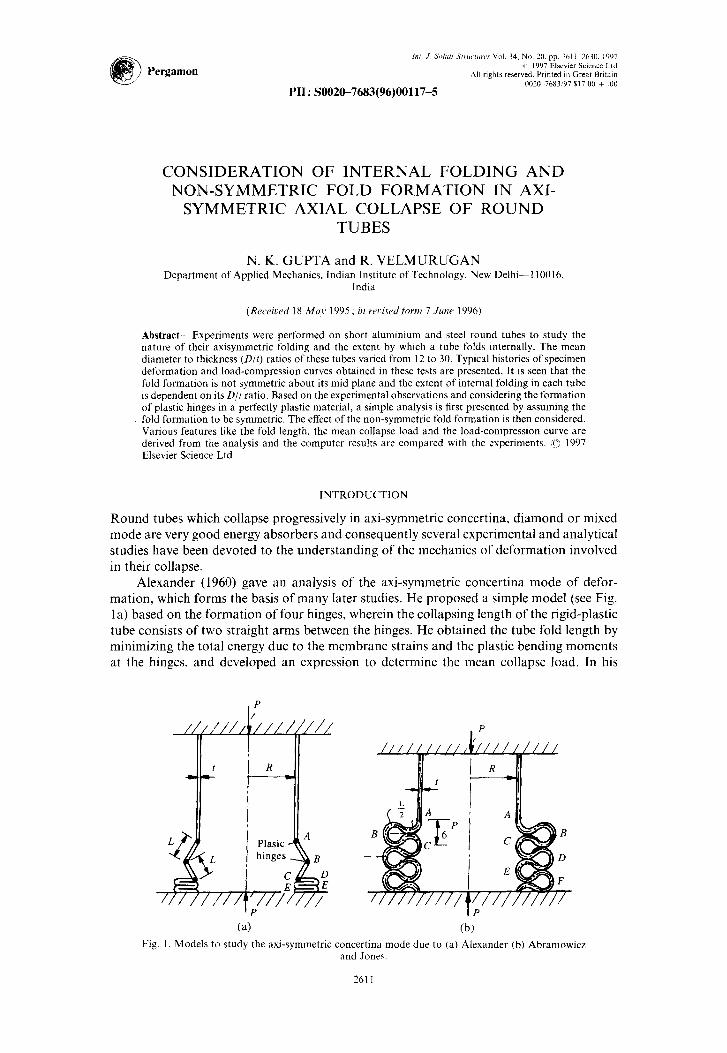
Alexander (1960) gave an analysis of the axi-symmetric concertina mode of defor- mation, which forms the basis of many later studies. He proposed a simple model (see Fig. 1 a) based on the formation of four hinges, wherein the collapsing length of the rigid-plastic tube consists of two straight arms between the hinges. He obtained the tube fold length by minimizing the total energy due to the membrane strains and the plastic bending moments at the hinges. and developed an expression to determine the mean collapse load. In his
P
/ /’
-i_
(4 (b)
//r R ! --I
Fig. I. Models to study the axi-symmetric concertina mode due to (a) Alexander (b) Abramowicz and Jones.
2611
2612 N. K. Gupta and R. Velmurugan
analysis, Alexander took bending moment capacity per unit length Mb = (1/2J’3)a,t’. where CT~ was the yield stress of the material. This simple model did provide very good results of the fold length L = 1.347fi (where R is the mean diameter of the tube), however, the mean collapse load is under estimated (see Grzebeita (1990)).
Abramowicz and Jones (1984) later modified Alexander’s model by introducing cur- vature in the deforming fold length (see Fig. l(b)). They used ultimate stress instead of the yield stress to account for the strain hardening, while the material considered was again rigid plastic. Effective crushing distance was introduced in their analysis and the mean collapse load thus obtained showed improved results. The bending moment capacity used in the analysis was Mb = (l/2,,/ 3)a,,r’ ( cu being ultimate stress) and the folding length was
found as L = 1.24fi (about 92% of the length found by Alexander). Both of the above analyses were directed towards determining the mean collapse load.
Grzebeita (1990), however, gave a method to determine the load history between a peak and a minimum in a load oscillation ofthe load-compression curve. The bending moment capacity that he assessed was Mb = (2/J 3)[ 1 - (3/4)P’] M,,. If the second term in the bracket
is neglected, one obtains M; = (31 vl?)M,, where M,, = a,,(t’/4) is the plastic moment per unit length. Grzebeita proposed a model wherein the curvature was confined around hinges, and the central span of length, equal to L/3. was flat. In his analysis the fold length was taken from the analysis given by Alexander (1960), arguing that it agreed with experiments quite well. In all the above analyses [Alexander (1960), Abramowicz and Jones (1984), Grzebeita (1990)], the Von-Mises yield criterion has been employed. Wierzbicki et ul. (1992) have studied the axi-symmetric collapse mode of round tubes by considering the internal folding. The half fold length determined in their analysis is L = 1.76&. The plastic hinge moment capacity taken by them is equal to the hinge moment, i.e. M,, = a,,(t”/4), where CT,, is the average Bow stress which is equal to 92% of the ultimate stress of the material. In this study it was shown that the load-compression curve is dependent on the internal folding, while the mean collapse load and the folding length are independent of it.
In the present study, experiments were performed on tubes of annealed aluminium and as received mild steel tubes, with Dir ranging from 12 to 30. All these tubes collapsed in concertina mode (see N. K. Gupta and S. K. Gupta (1993)), with folds forming both internally and externally. Their typical load-compression curves are presented. It was seen that the extent of internal folding varied with D/t. Typical histories of deforming specimens are presented to illustrate the mechanism of fold formation. Considering the fold formation to be symmetric and assuming the formation of plastic hinges. analytical expressions were obtained to determine the fold length. the mean collapse load, and the post collapse load compression curve. The results thus obtained have been compared with experimental results. Analysis shows that the fold length, mean collapse load and load compression curve depend on the extent of internal folding. An approximate analysis is then carried out by considering the fold formation to be non-symmetric, as observed in the experiments. Here, all hinge angles are taken to be different at any time. The post collapse load-compression curves thus obtained are presented and compared with experiments.
EXPERIMENTAL
Round mild steel and aluminium tubes with diameters ranging from 2.5 mm to 79 mm and thicknesses from 1.2 mm to 2.9 mm, were subjected to axial compression in an Instron machine. Aluminium tubes were annealed in an oven for 40 minutes at 3OO’C and were cooled for 24 hours, while steel tubes were tested in ‘as received’ condition.
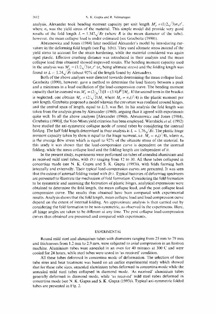
All these tubes deformed in concertina mode of deformation. The selection of these tube sizes and heat treatment was based on an earlier experimental study which showed that for these tube sizes. annealed aluminium tubes deformed in concertina mode while the annealed mild steel tubes collapsed in diamond mode. ‘As received’ aluminium tubes generally deformed in diamond mode, while ‘as received’ mild steel tubes deformed in concertina mode (see N. K. Gupta and S. K. Gupta (1993)). Typical axi-symmetric folded tubes are presented in Fig. 2.
Internal folding and non-symmetric fold formation in tubes ‘613
Fig. 2. Typical axis-symmetric folded round aluminium tube (D = 49.6 mm, t = 1.6 mm) and steel tube (D = 43 mm, t = 1.8 mm). (a) Typical concertina mode: (i) aluminium tube; (ii) steel tube. (b) Vertically cut deformed steel tube after seven folds. (c) and (d) Vertically cut steel and alumin-
ium tubes at different load levels.
Internal folding and non-symmetric fold formation in tubes 2615
0.5- o Aluminium
0 Steel
0.4- _ N= (
A = 1O.E = 225, 0.3 - n=3.1
N
0.2 -
0.1 -
I I 0 4 8 12 16 20 24 28 32 36
D/l
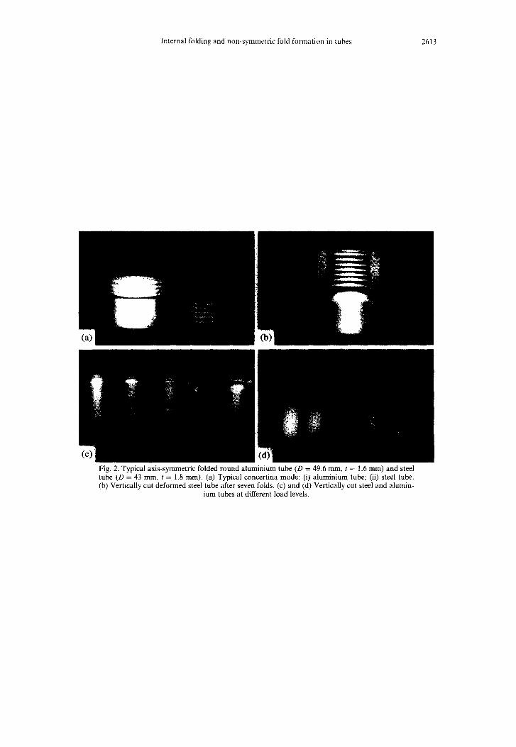
Fig. 3. Variation of N (ratio of internal fold to external fold) with D,‘f.
The internal and external fold lengths that were measured experimentally from the deformed tubes are given in Table 1. It is seen that the ratio (N) of internal folding to the external folding varies with tube dimensions. This variation is shown in Fig. 3, and is written in the form of the relation ;
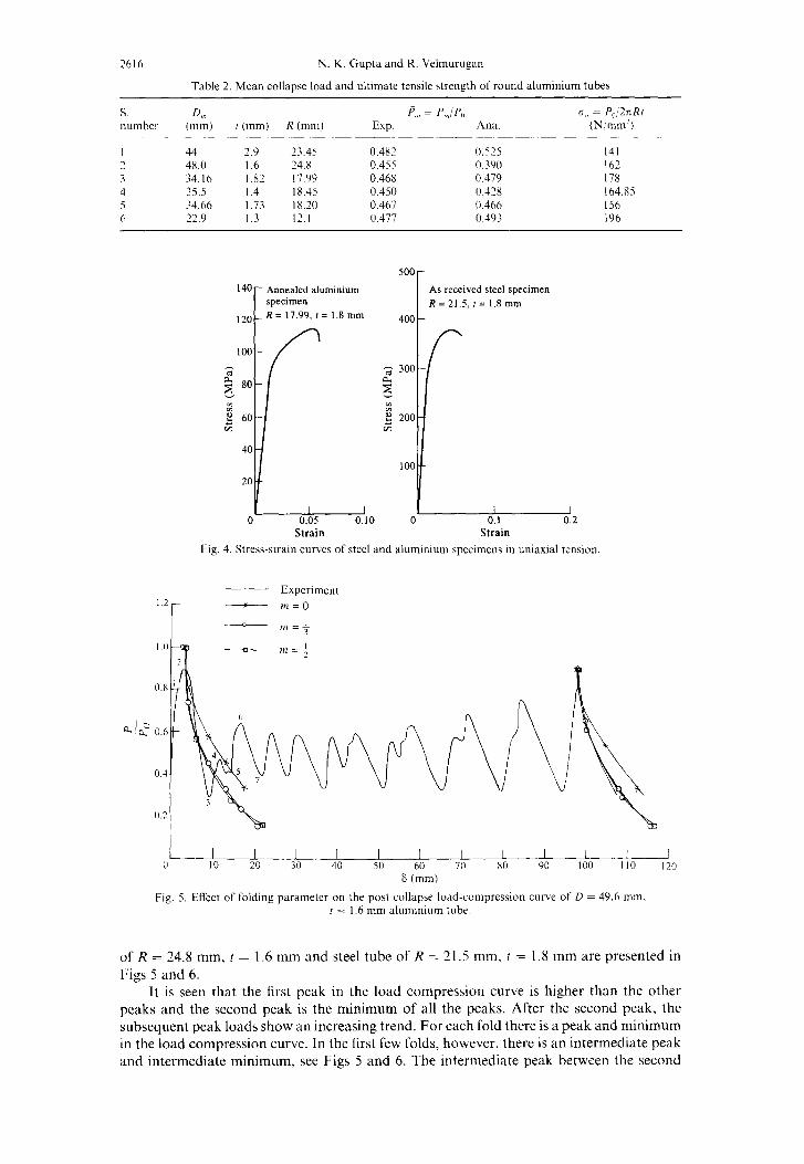
where A = 10, B := 225 and n = 3.1. The mean collapse load for all the tubes was calculated from the load compression curves, the values thus obtained for some typical tubes are presented in Table 2. The ultimate tensile strength of these tube specimens were obtained by testing the standard tensile specimens made out of these tubes and are reported in Table 2. Typical stress-strain curve of an annealed aluminium specimen and an as-received steel specimen are shown in Fig. 4.
To study the histories of deformation of the tubes in concertina mode, several alu- minium and mild steel tubes of identical dimensions were tested up to different load levels namely, the first peak, first minimum, first intermediate peak, first intermediate minimum. second peak and second minimum. Load-deformation curves for typical aluminium tube
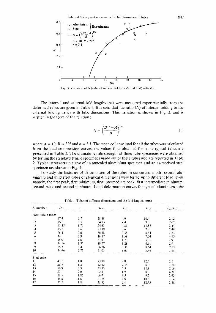
Table 1. Tubes of different dimensions and the fold lengths (mm)
S. number DZ, t D/i L,,, L Ill,l L,,U,iLl,,
Aluminium tubes 1 47.4 2 35.6 3 41.35 4 35.5 5 76.4 6 44 7 48.0 8 34.16 9 35.5
IO 34.66
1.7 28.88 4.Y 10.4 2.12 1.5 24.73 4.4 9.3 2.07 1.75 24.63 4.85 11.85 2.44 1.6 23.19 3.6 7.7 2.40 2.6 30.38 3.38 8.54 7.53 2.9 16.17 1.58 7.34 4.65 1.6 31.0 1.73 5.01 2.9 1.82 19.77 1.28 4.61 2.9 1.4 26.36 3.38 8.54 2.53 1.73 21.03 1 07 3.46 3.24
Steel tubes 11 12 13 14 15 16 17
41.2 1.8 23.89 -1.8 12.7 2.6 25.7 1.2 22.42 2.36 6.0 2.54 50.9 2.3 23.13 5.5 11.9 2.16 23 2.0 12.5 1.9 8.2 4.31 28.5 1.85 16.4 3.5 9.2 2.63 35.8 1.6 23.38 4.8 10.3 2.14 37.5 1.8 21.83 5.4 12.33 2.28
2616 N. K. Gupta and R. Velmurugan
Table 2. Mean collapse load and ultimate tensile strength of round aluminium tubes
s. D,ll number (mm)
I 44 2 48.0 3 34.16 4 35.5 5 34.66 6 72.9
r (mm)
2.9 I .6 I.82 I .4 I .73 1.3
R (mm)
23.45 24.x 17.99 1x.45 18.10 12.1
p,,, = p,,,: PC Exp.
0.482 0.455 0.468 0.450 0.467 0.477
AXi.
0.575 0.390 0.479 0.428 0.466 0.493
ci,, = P,,ZnR/ (N/mm’)
141 162 178 164.85 156 196
140 Annealed aluminium specimen
120 R = 17.99, f = 1.8 mm
As received steel specimen R = 21.5, r = 1.8 mm
400
- I I I
0 0.10 0 0.1 0.2 Strain Strain
Fig. 4. Stress-strain curves of steel and aluminium specimens in uniaxial tension
___ Experiment 1.2 -
I - m=O
0.8
0.6
I I I I I I I I I I I I 0 10 20 30 40 50 60 70 80 90 100 110 120
6 (mm)
Fig. 5. Effect of folding parameter on the post collapse load-compression curve of D = 49.6 mm. t = 1.6 mm aluminium tube.
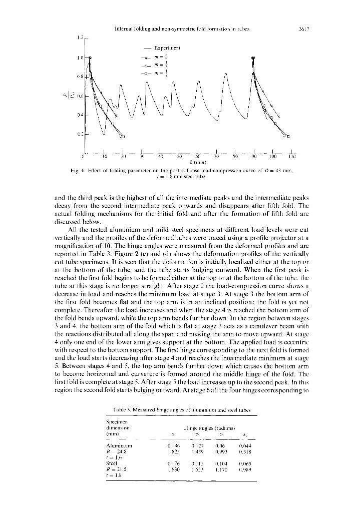
of R = 24.8 mm, t = 1.6 mm and steel tube of R = 21.5 mm, t = 1.8 mm are presented in Figs 5 and 6.
It is seen that the first peak in the load compression curve is higher than the other peaks and the second peak is the minimum of all the peaks. After the second peak, the subsequent peak loads show an increasing trend. For each fold there is a peak and minimum in the load compression curve. In the first few folds, however, there is an intermediate peak and intermediate minimum, see Figs 5 and 6. The intermediate peak between the second
Internal folding and non-symmetric fold formatjon in tubes 2617
l.‘
T _ Experiment
1.0 + m=O
0.8
1 I I I I I I I I I I I 0 10 20 30 40 50 60 70 80 90 100 110
6 (mm)
Fig. 6. Effect of folding parameter on the post collapse load-compression curve of D = 43 mm. t = I .8 mm steel tube.
and the third peak is the highest of all the intermediate peaks and the intermediate peaks decay from the second intermediate peak onwards and disappears after fifth fold. The actual folding mechanisms for the initial fold and after the formation of fifth fold are discussed below.
All the tested aluminium and mild steel specimens at different load levels were cut vertically and the profiles of the deformed tubes were traced using a profile projector at a magnification of 10. The hinge angles were measured from the deformed profiles and are reported in Table 3. Figure 2 (c) and (d) shows the deformation profiles of the vertically cut tube specimens. It is seen that the deformation is initially localized either at the top or at the bottom of the tube, and the tube starts bulging outward. When the first peak is reached the first fold begins to be formed either at the top or at the bottom of the tube, the tube at this stage is no longer straight. After stage 2 the load-compression curve shows a decrease in load and reaches the minimum load at stage 3. At stage 3 the bottom arm of the first fold becomes flat and the top arm is in an inclined position; the fold is yet not complete. Thereafter the load increases and when the stage 4 is reached the bottom arm of the fold bends upward, while the top arm bends further down. In the region between stages 3 and 4, the bottom arm of the fold which is flat at stage 3 acts as a cantilever beam with the reactions distributed all along the span and making the arm to move upward. At stage 4 only one end of the lower arm gives support at the bottom. The applied load is eccentric with respect to the bottom support. The first hinge corresponding to the next fold is formed and the load starts decreasing after stage 4 and reaches the intermediate minimum at stage 5. Between stages 4 and 5, the top arm bends further down which causes the bottom arm to become horizontal and curvature is formed around the middle hinge of the fold. The first fold is complete at stage 5. After stage 5 the load increases up to the second peak. In this region the second fold starts bulging outward. At stage 6 all the four hinges corresponding to
Table 3. Measured hinge angles of alummium and steel tubes
Specimen dimension (mm)
____
Hinge angles (radians) El x2 %; a.l
Aluminium 0.146 0.127 0.06 0.044 R = 14.8 I.825 1.459 0.993 0.518 I = 1.6 Steel 0.176 0.115 0.104 0.065 R = ‘1.5 1.830 1.513 1.170 0.989 f= 1.8
1618 N. K. Gupta and R. Velmurugan
the second fold are formed and stages from 1 to 6 are repeated for the first four to five folds.
Some tube specimens were tested up to 6 to 7 folds and were cut vertically. The fold formation after the 5th fold is different from the earlier folds and the intermediate peak in the corresponding load compression curve disappears after the fifth fold. In the earlier stages (first five folds) even after the minimum load is reached, the bending of the top arm of the fold is very much controlled by the bottom arm of the immediate fold to follow and the first hinge corresponding to this fold is formed only when the intermediate peak is reached. As soon as this hinge is formed the top arm of the earlier fold is allowed to bend freely and the fold is completely formed when the intermediate minimum is reached. In the first five folds, the fold is controlled by the next fold to follow. As the folding process continues the control of one fold over the previous fold decreases and becomes ineffective after five folds. Each fold is then independent of the next fold.
ANALYSIS
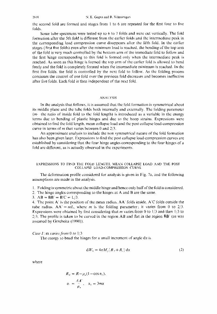
In the analysis that follows, it is assumed that the fold formation is symmetrical about its middle plane and the tube folds both internally and externally. The folding parameter (m-the ratio of inside fold to the fold length) is introduced as a variable in the energy terms due to bending of plastic hinges and due to the hoop strains. Expressions were obtained to find the fold length, mean collapse load and the post collapse load-compression curve in terms of m that varies between 0 and 2/3.
An approximate analysis to include the non symmetrical nature of the fold formation has also been given later. Expressions to find the post collapse load-compression curves are established by considering that the four hinge angles corresponding to the four hinges of a fold are different, as is actually observed in the experiments.
EXPRESSIONS TO FlND THE FOLD LENGTH, MEAN COLLAPSE LOAD AND THE POST COLLAPSE LOAD-COMPRESSION CURVE
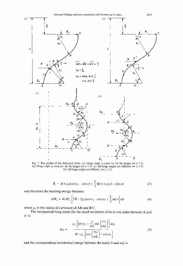
The deformation profile considered for analysis is given in Fig. 7a, and the following assumptions are made in the analysis.
1. Folding is symmetric about the middle hinge and hence only half of the fold is considered. 2. The hinge angles corresponding to the hinges at A and B are the same. 3. AB = BB’ = B’C = L/3. 4. The point A’ is the position of the mean radius. AA’ folds inside. A’C folds outside the tube radius. AA’ = ML, where nz is the folding parameter; it varies from 0 to 2/3. Expressions were obtained by first considering that wz varies from 0 to l/3 and then l/3 to 2/3. The profile is taken to be curved in the region AB and flat in the region BB’ (as was assumed by Grzebeita ( 1990)).
Cuse I: m caries from 0 to l/3 The energy to bend the hinges for a small increment of angle dx is
dW,, = hrM;,;R,fR,.) dci (2)
where
R, = R-p,(l -cosa,),
AA’ a, =-, cc, = 3mct
P,
Internal folding and non-symmetric fold formatlon in tubes 2619
(al -
L
RC
Q C
a
PCl
CC)
--
@
2
t_
a, = 3ma, m I f
=a,m>+
L
I
I
I
I
I
I
I
I
I
I
I
-+
I
I
I
Cd)
RH
---
RA Fig. 7. The profile of the deformed tubes. (a) Hinge angle is same for all the hinges (m < l/3). (b) Hinge angle is same for all the hinges (nz > IO). (c) All hinge angles are different (m 6 IO).
(d) All hinge angles are different (m > l/3).
R,. = R+p,,(cos~(, -cosc()+ $sinr+ptz(l -cost) (3)
and therefore the bending energy becomes
dW, = 4xMj, i
2R+2p,,(coscr, -cosr)+ fsinz dcc 1
(4)
where p. is the radius of curvature of AB and B’C. The incremental hoop strain for the small increment of da at any point between A and
A’ is
(5)
and the corresponding incremental energy between the limits 0 and nzL is
2620 N. K. Gupta and R. Velmurugan
In the region A’B the incremental Hoop strain and the corresponding incremental energy are given by
dW,,, = 2nG,jtL’{-rn(;-iz)?- 3iI ( _t - nzcosc(, - -COSCL + g,i(sing-since,) dx ; j ’ ]
(7)
Similarly in the region BB’
L p,(sinrdcc-sincx, dcx,]+7cos-*dt(
de,, = J
R+p,(cosx, -cosa)+ $sina
and between B’ and C,
L p,(sinada-sinrx, dcc,)+ jcosMdcr+p,sm
d&,, = ~~ _~ __--
L pO(~~~~, -cosa)+ 3slnx+p,
(8)
The total incremental strain energy for the small increment of da is
Internal folding and non-symmetric fold formation in tubes
dW,=dW,,+2;dW,,,+dW,,,+dW,,+dW,,,)
+4no,,rL~ i m(2m- 1) s’e”
2 since 2 +9-~~ + ~,1
i
I IMCOSC(l- jCOS”
3 1 . + ;-&sin:!-sina,)+ ,cosx dr.
I
From Fig. 7(a) the expression for the deformation S is given by
ii = L- f;cosl-2p,,sinr
2
Differentiating 6, the incremental displacement d6 is given by
2L 2sinr d6 = ,ol
i __ -3cosa+Xsinr
c(
263 1
(10)
(11)
(12)
The corresponding work done by the applied load is given by
dlV = Pd6. (13)
The post collapse load-compression curve corresponding to an oscillation from a peak to a minimum in a load-compression curve. is obtained by equating eqns (10) and (13).
EXPRESSIONS TO FIND THE FOLD LENGTH
The half fold length is obtained by minimizing the total potential energy with respect to L. Integrating the total incremental energy between 0 to a,,-the maximum hinge angle, the total energy is given by
x* = (14)
and
I’” = WZ(PH - 1) - sin a,,,)
1 1 + 3~
( i
1
f?l jcosx~Z-mcoscc,,,, + Zsm
Jm %, I = 3tm,,,
The total work done by the applied load is given by
(15)
2622 N. K. Gupta and R. Velmurugan
w, = Pb,
where 6, = 2L - t -2p,, is the effective crushing distance corresponding to one complete fold. Equating the above equations and minimizing with respect to L. the expression for L is given by
The maximum hinge angle x,,, is obtained from the equation
3ty+fL-2Lc(cosa-4c(sincx = 0 (17)
which is obtained by equating eqns ( 11) and (I 5a).
MEAN COLLAPSE LOAD
The final expression to find the mean collapse load corresponding to one complete fold is obtained by equating the total internal energy to the total work done by the applied load, and the final expression is given by
2Rct,,,+ $1 -cosa,,)+ TX*
(18)
The values of L, a, and P, are obtained by solving eqns ( 16). (17) and ( 18) iteratively.
Post collapse load-compression curve The post collapse load-compression curve (corresponding to the concertina mode)
from the peak to the minimum in an oscillation of the load-compression curve is obtained by equating the total incremental strain energy and the work done by the applied load due to the incremental displacement d6. The final expression to find the load-compression curve is given by
1 +47TcJ,,L’
i m(2nt- I)=1
2sina 2 + jj my- + G2
( mcosx, - jcosu
)
+ $&sin@-sinx,)I:coscz] = P r$] {e -2cosH+riinir) (19)
where
Internal folding and non-symmetric fold formation m tubes 3623
Here P = P/P”, where PO is the load corresponding to the ultimate stress (0,) in the uni- axial tension. For a known value of 6, c( is calculated from eqn (11) and is used in eqn (19) to get P.
Case II-Folding parameter m varies betuyeen 1! 3 and 2j3 In the previous case it was considered that VI varies from 0 to l/3. The same formulation
cannot be continued further, the reason being that the region AB is curved and BB’ is Aat. The position of radius R at A’ lies between B and B’ (see Fig. 7(b)). The mean radii at A and C are given by
and
respectively. Substituting these values in eqn (2). the bending energy term becomes
dW, =4nM~j2R+L(l-2m)sinxj dcc (21)
and the energy due to the hoop strains is given by
dW, -4n(i~tL2~~+{:+i((,,i-:j2+(:-m~)jcosirjdir. (22)
Equating the total incremental energy (d W, = d W, + d W,,) to the total work done by the applied load due to the incremental displacement d6 and substituting for ML and co in terms of A4, and o,, , the final expression to find the load deflection curve is given by
2cosccfasina - 4 I- ifj’ {2R+L(l-2m)sina) i J3 \ i
The expression to find the maximum fold length is given by
where
(24)
and the corresponding expression for the mean collapse load is
N. K. Gupta and R. Velmurugan
0 0.1 0.2 0.3 0.4 0.5 0.6 0.7 m
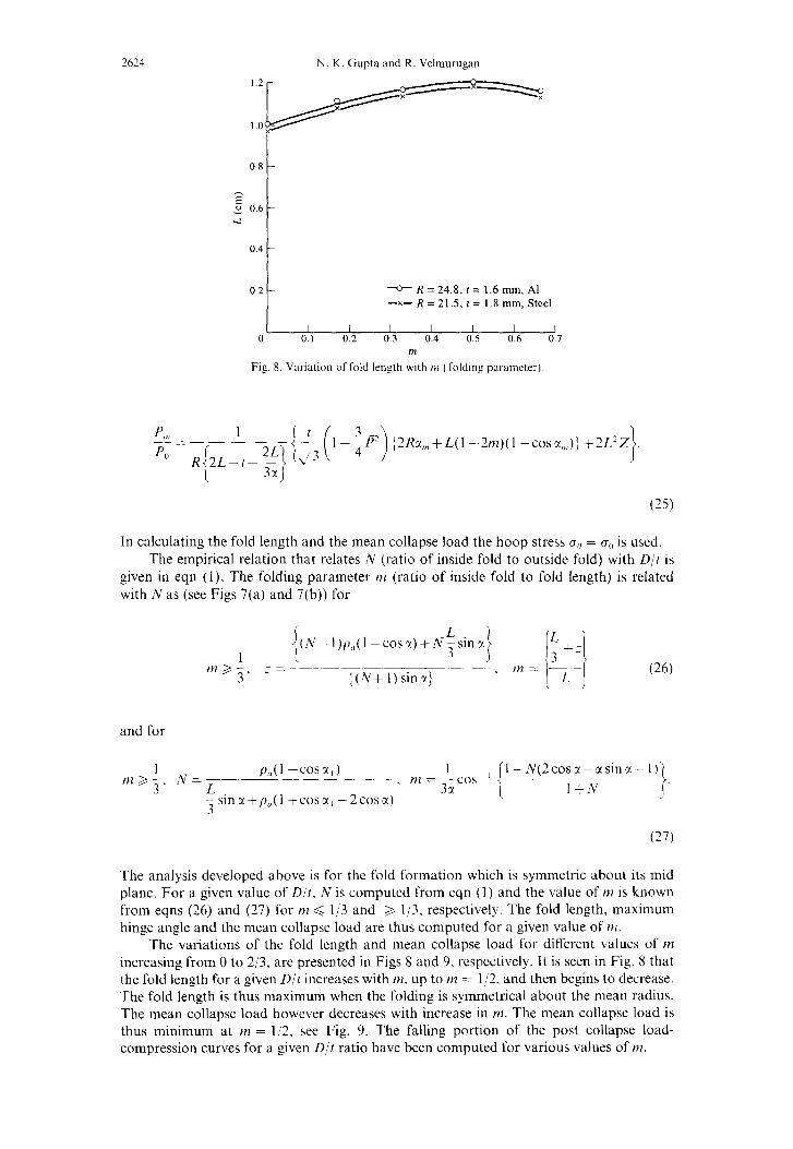
Fig. 8. Variation of fold length with IM ( folding parameter).
In calculating the fold length and the mean collapse load the hoop stress G,, = CJ() is used. The empirical relation that relates N (ratio of inside fold to outside fold) with D/t is
given in eqn (1). The folding parameter 1~ (ratio of inside fold to fold length) is related with N as (see Figs 7(a) and 7(b)) for
1 {(N-I)p.(l-corr)+fV$sin~
?,.j 3 __ = =~~_~~__-~-~.-~-~ ~ 3 ((N+l)smxj
(26)
and for
P<,(l -cosx(,) nl>;, NzL--- 1
- . n7 = 33( cos , l+N(2cos2-rsinx-1)
-sinr+y,(l +cosc(, -2cosa) i l+N
3
(27)
The analysis developed above is for the fold formation which is symmetric about its mid plane. For a given value of D/t, N is computed from eqn (1) and the value of IH is known from eqns (26) and (27) for MZ < l/3 and > l/3, respectively. The fold length, maximum hinge angle and the mean collapse load are thus computed for a given value of m.
The variations of the fold length and mean collapse load for different values of tn increasing from 0 to 2,‘3, are presented in Figs 8 and 9, respectively. It is seen in Fig. 8 that the fold length for a given D/t increases with ~1, up to nz = l/2. and then begins to decrease. The fold length is thus maximum when the folding is symmetrical about the mean radius. The mean collapse load however decreases with increase in HZ. The mean collapse load is thus minimum at PZ = 1,‘2. see Fig. 9. The falling portion of the post collapse load- compression curves for a given D/t ratio have been computed for various values of nr.
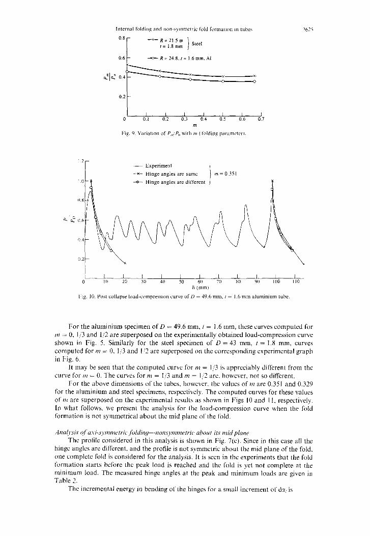
Internal folding and non-symmetric fold formation 111 tubes 2675
0.8
0.6
-x-R=21.5m f = 1.8 mm Steel
- R = 24.8, I = 1.6 mm, Al
I I I I I I I 0 0.1 0.2 0.3 0.4 0.5 0.6 0.7
m
Fig. 9. Variation of P,,,/P,, with ,)I ( folding parameter).
- Experiment
* Hinge angles are same
--g Hinge angles are different
L--L I I I I I I I I I I 0 10 20 30 40 50 60 70 80 90 100 110
6 (mm) Fig. IO. Post collapse load-compression curve of 11 = 49.6 mm, f = 1.6 mm aluminium tube
For the aluminium specimen of D = 49.6 mm, t = 1.6 mm, these curves computed for r~z = 0, l/3 and l/2 are superposed on the experimentally obtained load-compression curve shown in Fig. 5. Similarly for the steel specimen of D = 43 mm, t = 1.8 mm, curves computed for m = 0. l/3 and I,!3 are superposed on the corresponding experimental graph in Fig. 6.
It may be seen that the computed curve for m = l/3 is appreciably different from the curve for rn = 0. The curves for nz = l/3 and m = 1 /2 are, however. not so different.
For the above dimensions of the tubes. however, the values of vz are 0.351 and 0.329 for the aluminium and steel specimens, respectively. The computed curves for these values of nz are superposed on the experimental results as shown in Figs 10 and 11, respectively. In what follows. we present the analysis for the load-compression curve when the fold formation is not symmetrical about the mid plane of the fold.
.4nul~~si.s c?f usi-sq~nlnletric foldirlg--wons~mmrtri~~ about its mid plum The profile considered in this analysis is shown in Fig. 7(c). Since in this case all the
hinge angles are different, and the profile is not symmetric about the mid plane of the fold, one complete fold is considered for the analysis. It is seen in the experiments that the fold formation starts before the peak load is reached and the fold is yet not complete at the minimum load. The measured hinge angles at the peak and minimum loads are given in Table 2.
The incremental energy in bending of the hinges for a small increment of dcc, is
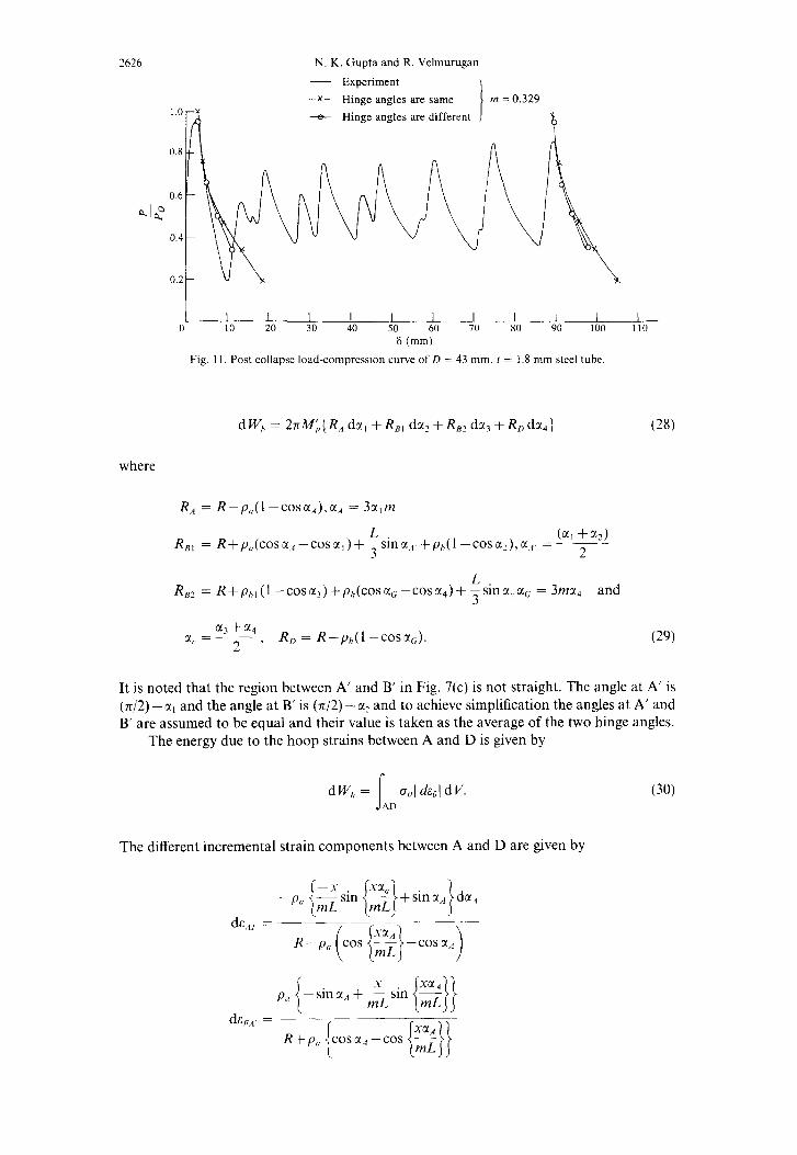
2626 N. K. Gupta and R. Velmurugan
- Experiment
--SC Hinge angles are same
+ Hinge angles are different
0.8
0 10 20 30 40 50 60 70 80 90 100 110 6 (mm)
Fig. 11. Post collapse load-compression curve of D = 43 mm. I = 1.8 mm steel tube.
dW, =2nM~{R,dcc,+R,,da,fRB2d~?+RDda,)
where
R, = R-p,(l -COSC(,),CI~ = 3c(,m
R,, = R+p,(cosa,~ L (a, +a,)
-toss(,)+ 3smr, +p,(l -co~fx~),a,~. =--- 2
Rs2 = R+phl(l -cosE~)+~,,(cosc~~;-cosc~~)+ isinc+a, = 3ma, and
m3+%
c1.=2’ ‘ Rn = R-p,(l -COSU~).
(28)
(29)
It is noted that the region between A’ and B’ in Fig. 7(c) is not straight. The angle at A’ is (742) -a, and the angle at B’ is (n/2) -a, and to achieve simplification the angles at A’ and B’ are assumed to be equal and their value is taken as the average of the two hinge angles.
The energy due to the hoop strains between A and D is given by
dW,, = gHI da,\ dV. (30)
The different incremental strain components between A and D are given by
Internal folding and non-symmetric fold formation in tubes 1627
p,[sinr, da,-sina,ddcc,}+
d& 4,F =
R+p,(COScc,--COsa,)+
p<, (sin o!, dcc, - sin CX.~ da,, ]
R+p,(cosdcr,-cosa,)+ isinn,,-p, I -cos
de,, =
R-p, (,,, i(2L;;)~~}_Cosx,;)~
-sina,+ 2L-x
c’h x sin {%;&I} dgG
ph {sin 6!, du, - sin xc dcc,) +
dEc.C = __-__-
R+p,,(coscc,-cosa,)+
pl, [sin CI~ da, -sin czG dz,J
+ ~cosar,da,,+p,,
R+pt,(cosda,--coscr,)+ $sin&.-p,,
The corresponding energy terms are given by
L
3
-
,
-
1. (31)
dw,, =2na,,t{m~}? da,
1 1 1 + 3~;
4 vz cos xc - ?cos x4 + $sm CI, -sin (x,)
4
1 dW h 7 -r~sinr,+ 3 mmsinr,
dz, I - + 6 -o(,< cosqdx,. 34 (32)
and
The total energy is given by
dWT = dWb+dW,,, +dW,,~+dW,/;,~+dW~~~+dW,,+dW,,~+dW,,~+dW,~~. (33)
From Fig. 7(c), the expression for the deformation d is given by
L L n‘ = 6,+6,, = 2L-p,,sinr,- -cosx,.-p,,, since; -ph sin%? - m-coscxl -PC, sina,.
3 3
(34)
The incremental deformation d6 is given by
Internal folding and non-symmetric fold formation in tubes ‘629
The expression for the post load compression curve is obtained by equating the total incremental energy to the incremental work done by the applied load
dW, = Pd6. (36)
For the known value of ai, d6 is calculated from eqn (35) and the corresponding P is obtained by equating eqns (33) and (36). The value of the fold length in this analysis is taken from the symmetric case.
In the case of m >, l/3,
R, = R-pa(l -cosu,)-(no-;)LCOSQ
R,, = R+($~)Lcos~,,~+p,(l-cosslz)
RB2 = R+(;-m)LcosxC+PU(l -cost(,)
R, = R-p,(l -cosr,)-(nz-f)Lcoscc,
The energy due to the hoop strains are
L’ -t ~~ccJ,~,, t T
dW,,z = 2na,,,,tp -------cos ozl. dr, 2
dw,,, = 2no,, t-+-cosa,,,du,
dW,,, = 2na,,t- COSX4 + 7_ _. s’““4 da,
a, CC.:
d W,,, = 2rw,& 2
cos z<- du,
d W,,, = 2zo,+ct
1630 N. K. Gupta and R. Velmurugan
dW,,, = 271o,,,f y -nzL fcosa,idz<; C 1
The total incremental internal energy is
d Wr = d W,, + d W,, here
dW,, = dW,,, +dW/,2+dW,z~+dW,,J+dW,,5+dW,,h+dW,,7+dW,~X
d W, = 2nM;:R., da, + Rm du: + RB2 dr, + R,j dx,;
The computed falling portion of the load-compression curve for a aluminium tube of D = 49.6 mm, t = 1.6 mm is shown superposed on the experimental results and those obtained from the analysis of the symmetric case in Fig. 10. In Fig. 11, similar results for a mild steel tube of D = 43 mm, t = 1.8 mm are presented.
It is seen that the results obtained from the analysis which considers the fold formation as asymmetric about its mid plane match the experiments better.
CONCLUSIONS
Experiments in axial compression of aluminium and mild steel round cylinders which collapse in axisymmetric concertina mode show that the tubes fold both internally and externally. The extent of internal folding is seen to depend on D/t ratio. Both the fold length and the mean collapse load vary with the variation in folding parameter HZ.
The actual fold is seen to be nonsymmetric about its mid plane. Analysis is first presented by considering the fold formation to be symmetric and the results are compared with the experiments. It is seen that the fold length increases with the increase in the folding parameter from 0 to I:‘2 and thereafter it begins to decrease. Thus the fold length is maximum when internal and external folding are equal. The mean collapse load is minimum when internal and external folding are equal. Analysis for the non-symmetric fold formation is also presented for the case when the fold formation is non-symmetric about the mid plane of the fold. The results obtained are seen to fit the experimental results better.
Ach-n~,lI.IL’~~~:Yenl(‘)lt--This work was done under a project sponsored by the structures panel of the Aeronautical Research and Development Board. Directorate of Aeronautics, Ministry of Defence (R&D). New Delhi. India.
REFERENCES
Abramowicz. W. and Jones. N. ( 1984). Dynamic axial crushing of cucular tubes. Irtter.ncrtionu/ Jorrrr~l of Irq~/ Enginewiq 2, 263-Z 1.
Alexander, J. M. (1960). An approximate analysis of the collapse of thin cylindrical shells under axial loading. Quarterly Jourr~al of Mechanics and .4pplid Mathematics 13, 10-I 5.
Grzebeita, R. H. (1990). An alternative method for determining the behavtour of round stocky tubes subjected to an axial crushing load. Thin UhlkJ Structurrs 9, 61-W
Gupta, N. K. and Gupta. S. K. (1993). Effect of annealing. size and cut-outs on axial collapse behavjiour 01 circular tubes, Intcvwational Joumul qf Mechanical Science 35, 597 -6 13.
Wierzbicki. T. Bhat. S. U.. Abramowicz. W. and Brodkin. D. (1992). Alexander revisited -A two folding elements model of progressive crushing of tubes. fr~ternafionul Journal ofSo/itf.~ ard S/ructures 29, 3269 3288.