Embed Size (px)
Citation preview
J.H. RALL FEBRUARY 2006
1
SOUTH AFRICAN COLLIERY ENGINEERS ASSOCIATION TECHNICAL SYMPOSIUM 1. A CONSIDERATION OF DRIVES IN THE MINING INDUSTRY
The largest number of drives would normally be on material handling equipment and this paper concentrates on those drives. It will hopefully encourage an understanding which can be applied in a variety of cases to work towards lowest owning and operating costs, rather that low initial cost and high running costs and low reliability.
In general the gearbox or speed and torque change device is as important as any other vital part of machinery as its malfunction would affect the entire process to which it is employed. In many cases the cost of the drive train is small in comparison to the rest of the driven machinery and tends to be neglected, as it does not normally “scream” for regular attention. Unfortunately, the saying of “a stitch in time saves nine” is rarely more applicable than in industrial gearboxes.
In a 3 stage speed reducer with surface hardened and ground gears, as a very rough estimate, bearings make up approximately 5% to 10% of the costs, the gears approximately 45% to 55%, housing covers, low speed shaft, and other non-wearing hardware, 35% to 40%. Apart from accidents or abuse the main wearing parts are normally the bearings and the uncorrected wear of a bearing, which may be only 1% of the costs can be the cause of progressive damage to the rest of the rotating parts.
Normally, the calculated expected life of the various bearings will easily be a factor of 5 between the highest and lowest expected life. Careful analysis of requirements, specifying and enforcing the written specification blindly, and harshly, will pay handsome dividends.
2. INDUSTRIAL GEARING 2.1.1 A Look at Involute Gearing (a reminder)
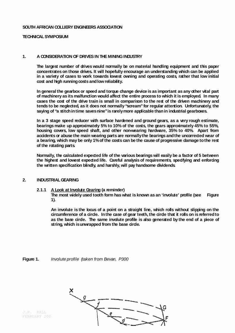
The most widely used tooth form has what is known as an ‘involute’ profile (see Figure 1). An involute is the locus of a point on a straight line, which rolls without slipping on the circumference of a circle. In the case of gear teeth, the circle that it rolls on is referred to as the base circle. The same involute profile is also generated by the end of a piece of string, which is unwrapped from the base circle.
Figure 1. Involute profile (taken from Bevan, P300

J.H. RALL FEBRUARY 2006
2
2.1.2 Conjugate Action To be able to transmit a uniform rotary motion from one shaft to another the peripheral speeds at the pitch circles of the two gears must be identical. Referring to Figure 2, one can imagine the two gears as two cylinders of diameter the same as the base circle connected together by means of a non-extendable band along the line of action.
Figure 2: Involute Teeth – exaggerated clearance.

J.H. RALL FEBRUARY 2006
3
A single point on this band would generate an involute from each of the two base circles and as the same point generated both involutes it is clear that the involute tooth profile would duplicate the movement of the two base circles at exactly the same peripheral speed. It is important to note that any variations from the true involute tooth shape will introduce varying circumferential speeds between the teeth and consequently generate vibration, noise and other problems. The angle that this line of action forms with a tangent to the two pitch circles is the pressure angle.
At the pitch point the contact between the two involute teeth is purely rolling. Above and below the pitch point along the line of action there is relative sliding between the tooth surfaces. The velocity of sliding is proportional to the distance from the pitch point. It is also clear that the involute profile is not affected by distance between the centres of the base circles. Small variations in centre distances of a gear set will there for not affect the accuracy of the transfer of rotational speed from one gear to another. A small variation in “Backlash” is therefore irrelevant.
2.1.3 Involute Generation
Figure 3, shows some teeth of a rack and pinion engaged. It can be seen from this that as the radius of the base circle is extended to infinity; the involute line becomes a straight line at right angles to the line of action. The majority of gear generating equipment uses this principle and the involute is therefore generated by a series of flats that approximate the involute profile. These are generated by a cutter with a tooth profile of the straight-sided basic rack. There are some grinding machines that generate a true involute by mounting the gear onto the shaft which is attached to two steel discs of the same diameter as the base circle and two steel bands hold the discs so that as the shaft is moved a true involute is generated. Figure 3 : Some teeth of a rack and pinion engaged.
Axis Rack Path of Contact

J.H. RALL FEBRUARY 2006
4
Base Circle Pitch Circle Base Pitch
2.1.4 Contact Ratio Clearly in order to obtain continuity of motion, one pair of teeth must pick up the drive before a previously engaged pair has disengaged. While over a considerable portion of the cycle of contact the load is borne by one pair of teeth, at the beginning and end it is shared between two pairs of teeth. Figure 4 shows the zone of meshing of a tooth. Contact of the teeth begins at the intersection of the addendum circle with the pressure line or line of action and ends with the intersection of the other addendum circle with the same pressure line. The sum of the arcs of approach and recess is the arc of contact. For one tooth to pick up the drive before another has disengaged, the circular pitch of the gear teeth must be less that the arc of action. The contact ratio is the ratio of the arc of action divided by the circular pitch and in modern gearing this would vary between 1.4 and some higher figure for high speed, quiet, gearing. Figure 4 : The zone of meshing of a gear tooth (from Shigley, p 581)
2.1.5 Helical Gearing

J.H. RALL FEBRUARY 2006
5
Another method of improving the smoothness of load transfer from one tooth to the other is to cut the teeth on a helix. (see Figure 5). The teeth are therefore not in line with the axis of rotation but are at an angle to this. This transfer of load from one tooth to the other therefore occurs progressively over the width of the tooth face in the case of the helical gear. The helix angle induces an axial thrust, which has to be absorbed by the shaft bearings. The larger the helix angle, the more gently the transfer of loads but the larger the thrust on the bearings. In modern gearing, therefore, the helix angles are kept as small as possible and with a good quality of involute profile very efficient power transmissions is achieved.
Figure 5 : Helical gear and rack. (taken from Dudley, p. 2-6)
2.2 Developments to Improve Gear Ratings
Assume that one starts with a gear set made from alloy steel through hardened to between 30 HRC and 35 HRC. The calculation will yield a rating for surface durability (Hertizian Stress) and for root bending strength. The strength rating is likely to be much higher than the durability.

J.H. RALL FEBRUARY 2006
6
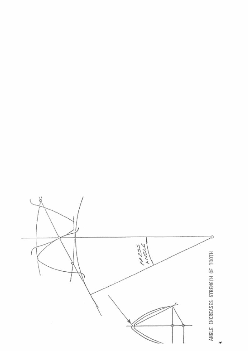
The first improvement is therefore the use of alloy steel which is suitable for surface hardening. Surface hardening can be done by induction, or flame hardening, or nitriding or gas carburising etc. As an example with a material such as 655H13 to BS970 or 17 Cr Ni MoS6 according to D.I.N. 17210, a surface hardness around 60 HRC is achieved to a depth of approximately 1mm and a core hardness of 40 HRC to 45 HRC. The allowable surface pressure will increase dramatically and is likely to be higher than the bending strength. To take advantage of the higher surface durability, corrections can be made to the teeth by adapting the centre distances and so the working pressure angle. The effect of this is to produce a tooth broader at its base and smaller at the tip to give improved bending strength, as shown in the diagram of macro geometric changes. It is not essential but a good philosophy to follow, to aim for a design, which has a higher strength rating than durability rating. Under overload or abuse, the teeth are therefore more likely to suffer surface damage than to break out resulting in catastrophic failure. The increase in working pressure angle does increase the radial component relative to the tangential component increasing the bearing loading for a fixed torque. A reasonable balance must therefore be aimed for. Modern high torque gearing would therefore be surface hardened and use a working pressure angle of the order of 25º and a helix angel below 10º. The copy of page 12 of DIN 3961 gives a comparison of the various quality numbers.
SEE COMPARISON ON NEXT PAGE…………………………………Pg8

J.H. RALL FEBRUARY 2006
7
J.H. RALL FEBRUARY 2006
8
GEO
MET
RIC
CH
ANG
ES

J.H. RALL FEBRUARY 2006
9

J.H. RALL FEBRUARY 2006
10

J.H. RALL FEBRUARY 2006
11
2.3 Gearbox Bearing Layouts and Developments
2.3.1 Bearing Types: Standard catalogued bearings fall into two main groups – ball and roller bearings.
Ball bearings use a spherical rolling element and roller bearings use a variety of rollers as rolling elements, such as, cylindrical, taper and various types of crowned rollers. Fig. 2.1, 2.2 & 2.3.
Bearing choice is influenced by many criteria such as available space, loads, speed, alignment, requirement for precision, silence or stiffness, need for ease of displacement or mounting and stripping etc.
In gearboxes, the main consideration in bearing choice is the load. Standard ball bearings i.e. deep groove ball bearings are normally only used in smaller gearboxes. They can take radial as well as axial loads. Angular contact bearings are designed to accommodate mainly thrust loads and/or radial loads. Without thrust load their radial location is lost.
The 4-point contact ball bearing is designed exclusively for thrust in both directions and it would normally be fitted with clearance on its outside diameter to avoid it taking radial load. Roller & ball thrust bearings are also only for thrust loads and are normally fitted with no radial location.
Spherical roller bearings can accommodate radial as well as thrust loads but again they are primarily designed for radial loads and can accommodate thrust loads only if the radial load is dominant. Taper roller bearings can accommodate radial as well a thrust loads and the balance between radial and axial loads depends on the taper angle of the bearing. It is important to remember that a radial load on the bearing will generate an axial load.
There are other variations such as the spherical thrust bearing and needle and full complement roller bearing. Apart from the spherical roller bearing, the spherical roller thrust bearing and the new S.K.F. CARB bearing, others are adversely affected by misalignment.
Parallel roller bearings (without lips on either side of one race) are good for radial loads but can accommodate no axial load. Arrangements with lips on the races can accommodate thrust but the thrust faces slide rather than roll. In the standard roller bearing the contact is as near as possible to pure rolling.
The middle industrial range of gear units now under consideration use mainly parallel, taper, spherical roller and thrust bearings.

J.H. RALL FEBRUARY 2006
12
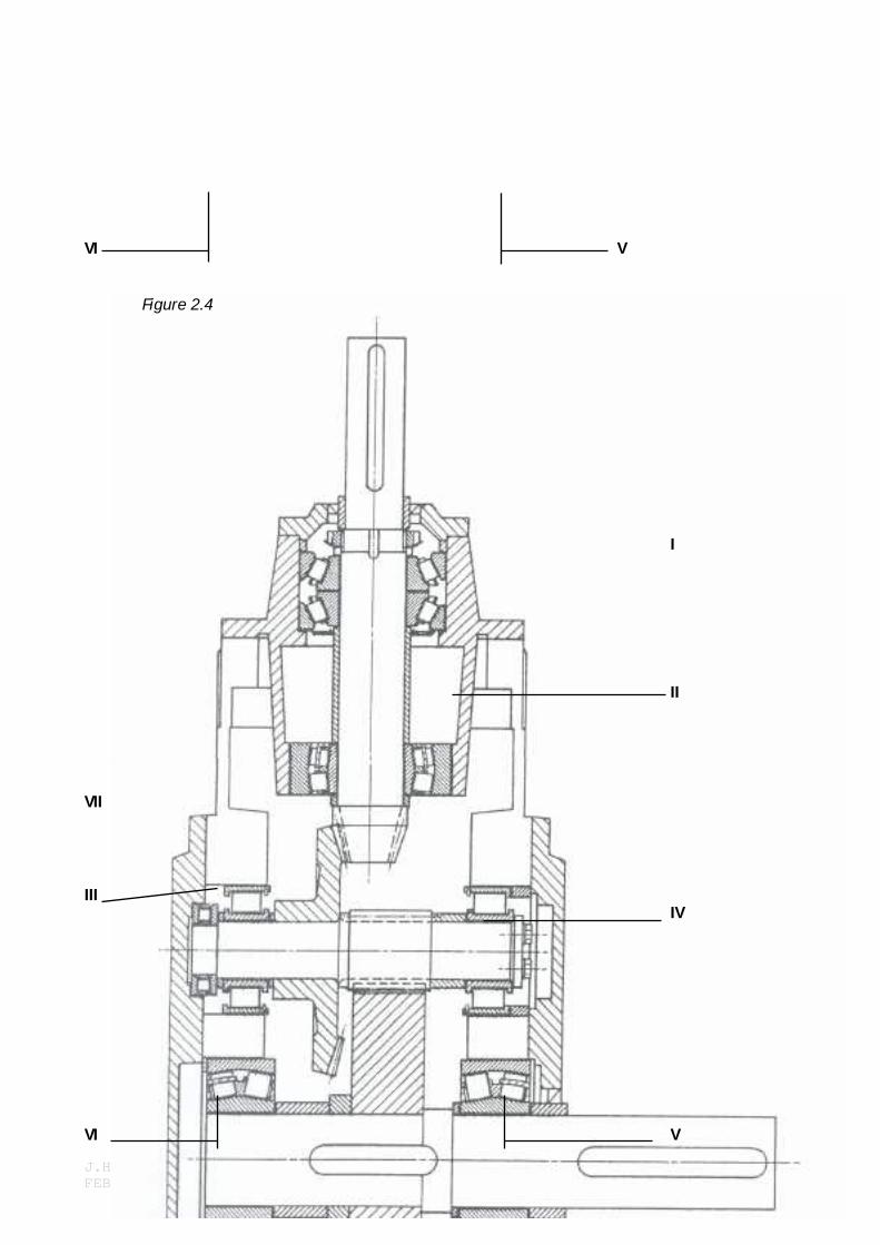
2.3.2 Bearing Loading Consider a typical bevel / helical gearbox shaft layout in Figure 2.4.
Ignoring external loads, the high-speed shaft will have a load approximately vertically up or down (say 20º from vertical along the pressure angle dependent on direction of rotation) at the gear teeth, and a load along the shaft probably away from the gear depending on the spiral angle of the bevel.
The intermediate shaft will be subjected to two (determined by pressure angle) approximately vertical loads up and down (depending on direction of rotation) and two forces along the shaft; one the thrust from the bevel gear and the other the helix thrust. They may act in the same direction or oppose each other.
The low speed shaft will again have two forces acting on it, the approximate vertical load between the gear teeth, and the helix thrusts both being equal and opposite to two of the forces on the intermediate shaft.
Figure 2.4 shows the layout of a set of bearings with bearing II set to take only radial load. Bearings III, IV, V and VI are all arranged for radial and thrust load.
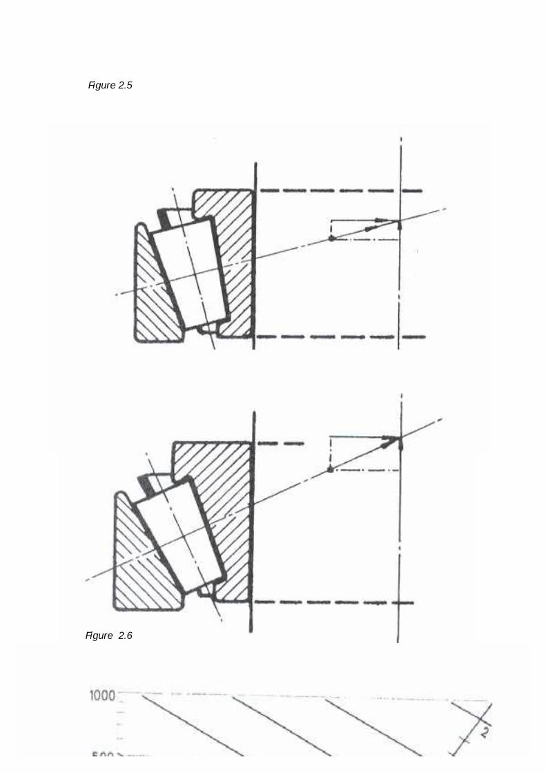
For simplicity, consider the low speed shaft bearing, Fig. 2.5 as drawn; bearing V being nearest to the wheel will sense the helix thrust and more than half the tooth load. Bearing VI will sense externally only the radial tooth loading, but due to its construction it resists loads perpendicular to the track and the radial load therefore causes a thrust component. This thrust component has to be resisted by bearing V in addition to the two gear loads. This induced thrust, as well as the gear thrust is partly resisted by the thrust induced by the radial load. The pair of steep angle taper roller bearings at ‘I’ cause larger induced thrust from radial load and consequently resist thrust with a relatively smaller induced radial load.
The spherical roller bearings at ‘V’ and ‘VI’ in Figure 2.5 and the parallel rollers at ‘III’ and ‘IV” do not normally induce thrust loads from radial loads (except where the spherical rollers are preloaded against each other). The roller thrust bearing at ‘VII’ would resist the bevel and helix thrust leaving the parallel rollers only the radial load to cope with.
2.3.3 Load Criteria
Bearings can become unsuitable for service in gearboxes for two main reasons. Fatigue and flaking of the tracks and rolling elements or wear, both of which cause excessive clearance.
The generally accepted life calculation is based on the catalogued rating of the bearings determined by its fatigue life. Two definitions are roughly quoted from leading bearing manufacturers:-
The rating life of a comparatively large number of identical bearings running under identical operating conditions is defined as the number of revolutions attained or exceeded by 90% of the bearings tested before the firt evidence of fatigue failure develops. 10% of the bearings tested may fail earlier. The basic dynamic load rating, C, which is used for calculations involving dynamically stressed bearings expresses the bearing load which will give a basic rating life of 1 000 000 revolutions – Dynamic load ratings are based on the life that 90% of a sufficiently large group of apparently identical bearings can be expected to attain or exceed.
Statistically the median life is approximately 5 times the calculated rating life.

J.H. RALL FEBRUARY 2006
13
q C P
10/3 1000000 C 60 xn P
In practice, a bearing may become unserviceable due to excessive wear rather than from fatigue and this was discussed earlier. A considerable amount of damage is caused to gears due to excessive clearance or wear in bearings.
2.3.4 Static Capacity:
Co, the basic static load rating is the load, which will produce a total permanent deformation of the rolling element and raceway on the most heavily stressed rolling element/raceway contact of 0,0001 of the rolling element diameter. A later I.S.O. recommendation has changed this and the manufacturer’s catalogue should be studied for the correct information.
This Co ratings needs to be considered on slow moving bearings and bearings subject to heavy shock loads. It is especially important in industrial gear units subject to external static loads on shaft exteriors.
2.3.5 Bearing Life Formula
Fatigue: The relationship between the basic rating life L10, the basic dynamic rating C and
the bearing load P is expressed by L10 in millions of revolutions reached before 10% of the bearings fail.
For roller bearings, exponent q is 10/3 and 3 for Ball bearings.
Thus in hours, “L10”, bearing life is
Where ‘n’ is the rotational speed in rev. per minute. For gearbox catalogue purposes, the generally accepted convention is to calculate the power, the gearbox can transmit in Kw for a calculated L10 life of 5000 hours, of necessity this must exceed the calculated Kw rating of the weakest element.
The actual load ‘P’, on a bearing to be used in the life calculation, has to be a realistic average. On applications like a fan, the maximum calculated absorbed power is likely to be present for the majority of the running time and will be affected by temperature, air density, wind and back pressure etc., which may cause variations of ± 10%.
A conveyor on a mine is likely to run on some overload for say 5% of the time – on full load 30% of the time and the rest of the time can range down to no load. To use the maximum calculated absorbed power for the bearing life calculation is unrealistic and an objective average needs to be determined by the system designer. On the other hand, if the system designer specified the average as 90% of motor power, the gearbox supplier is obliged to calculate bearing life with this load.
2.3.6 Wear:
The following is an edited extract from the literature of a bearing manufacturer:
“The amount of wear causing an increase in radial clearance depends on the bearing bore diameter and other bearing characteristics. Wear life depends on conditions at the rolling or sliding surfaces and on the accuracy demanded by the machine. In clinically clean test running conditions with perfect lubrication, there would theoretically not be wear and the bearing life would depend on the fatigue life.”
In practice, there is usually some contamination of the lubricant, which depends on the environment. In the consideration of gear quality, one can translate the

J.H. RALL FEBRUARY 2006
14
10/3 C P
allowable deviation in helix angle into a movement from wear, which will determine acceptable wear allowance. The wear life is to a large extent under the control of the end user and not the gearbox designer.
2.3.7 Life Adjustment Factors
The adjusted life Lna is the product of the calculated life and the adjustment factors for; all failure probability (or reliability), A2 material and A3 operating conditions (or application conditions)
Lna = a1 x a2 x a3 = (for roller bearings)
By definition of the catalogue rating of the bearing factor ‘a1’ is unity for a 10% chance of failure or 90% reliability. For other probabilities the following table indicates values of ‘a1’.
FAILURE PROBAILITY: 10% 5% 4% 3% 2% 1% RELIABILITY: 90% 95% 96% 96% 98% 99% VALUE ‘a1’ 1 0.62 0.53 0.44 0.33 0.21
The material adjustment factor ‘a2’ = 1 for “normal” through – hardened rolling bearing steel (or steels on which ISO 281 equations are based). Leading manufacturers use better steels such as vacuum de-gassed vacuum re-melted and electro slag re-melted steels. This factor changes with operating conditions and the bearing manufacturers include it with the operating conditions or application conditions) to from factor a23.
Quoted from catalogue of a leading manufacturer:- “The highest life values are reached with a hydrodynamic state of lubrication, that is, where no metal-to-metal contact exists between rolling elements and raceways. Under such lubricating conditions the extended life of the vacuum re-melted steels is fully exploited.
These optimum conditions, however, are not present with a thinner lubricating film and increasing metal-to-metal contact.
At hydrodynamic lubrication the formation of pitting emanating from in-homogeneities in the subsurface of the raceway terminates the life. At mixed friction fatigue damages arise at the surface of the raceways. Hence, in the case of mixed friction the advantages of the improved steels are null and void, therefore, it may not be assumed that the life can be extended by using a cleaner steel.”
2.3.8 Life Adjustment Factor a23:
With the interdependence of the adjustment factors for material (a2) and application conditions (a3) the combination factor (a23) is used. (See diagrams) Figures 2.7 / 2.8 and 2.9.
As modern gear units are invariably lubricated with extreme pressure oil of suitable viscosity for the operating temperature, the factor ‘a23’ will be above one, except for very slow running bearings. Part of the actual practical effect of this factor is in the hands of the user and a practical realistic figure is determined by the graphs and so influences calculated bearing life considerably. In specifying a calculated expected bearing life, the buyer should indicate from his knowledge of operating conditions, the factors to be used, or at least ask what factor the supplier used for this. It can be seen that by moving from the pessimistic to the

J.H. RALL FEBRUARY 2006
15
optimistic view on the graph, the calculated bearing life can be doubled. The factor to be used is partly under the control of the end user.
In ideal conditions of lubrication and loading the latest theory points to the possibility of much higher adjustment factors than 3, and it is therefore now more important that this factor used should be noted in comparisons.
The likely life of a gearbox bearing in service is more dependent on the end user that the gear unit manufacturer and special attention should be given to type, quality and viscosity of gear lubricant to ensure good bearing and therefore gear life.
2.3.9 Temperature:
Operating temperature may also affect bearing life and the factors given by the leading manufacturers differ depending on whether they are applied like the above ‘a’ factors or applied to the catalogue rating (in which case it is inside the brackets).
They quote a factor 1 for a temperature of 150ºC indicating that at that temperature bearing life is not reduced.
This refers to actual metal; temperature and a considerable temperature difference can be expected between lubricant and bearing surface with poor lubrication. With a modern design providing for adequate lubricant movement the limiting element is normally the seal material or the lubricant life.
A gearbox operating temperature of 120ºC using the correct lubricant can be accepted without affecting the life. With standard mineral oils and neoprene seals 90ºC is a realistic practical maximum operating temperature.
2.3.10 Shaft Deflections:
Under operating loads, shaft deflections, no matter how small, do occur and these cause bearing misalignment. Figure 2.10 roughly shows the effect of shaft deflection on various bearing types.
The worst affected are the deep groove ball race and the pair of tapered roller bearings with cups facing outwards and standard parallel roller. Spherical roller bearings and barrel roller bearings are manufactured specifically to accommodate misalignment without any influence on operating life.
In practice, spherical roller bearings are available in an extensive range of sizes and they also have relatively high load carrying capacity per shaft diameter as well as being able to resist some thrust and they are therefore a popular choice for larger shaft sizes.
The full complement (cage-less) roller bearings also offer relatively high load carrying capacities and high reliability. They are well suited to modern gearbox applications.
2.3.11 Bearing Life (Statistical Distribution)
Information extracted from papers published by two leading European Bearing Manufacturers on their work is quoted here. When fatigue tests are conducted they have to be completed in reasonable times and runs of 5 million to 100 million revolutions are aimed for.
Returning to the life formula, this means running under a load of between 20% and 60% of the dynamic RATING. In practice, the mean range of application is quoted as being between 8% and 15% of the rating requiring extrapolation of the

J.H. RALL FEBRUARY 2006
16
test results. “It has not yet been clarified whether and to what extend very low loads might result in a horizontal life curve identifying indefinite life. None of the result so far conducted up to 500 million revolutions – have proved the existence of indefinite life”.
Bearing life experiments are done under controlled conditions and the leading manufacturers appear to agree that the Waybill distribution fits the experimental data better that the standard distribution. The histogram shown in Figure 2.11 is taken from “Design of machine element” (Vergil Monitoring Fears) and it shows the skewed distribution.
Unfortunately the life scale is not given but if it were to be taken as approximately 2 million revolutions per division ie. 24 million total, then the L10 life would be about 2 million and the median life 9 million, and it would fit the generally accepted statement that the L50 life is between 4 and 5 times the L10 life (above ref. quotes the same).
In practice therefore, one can never eliminate a failure belonging to that acceptable percentage say 10% occurring in the early part of the life of a machine.
Again quoting a manufacturer: “fatigue causes flaking of the tracks and/or rolling elements.” Flaking of the raceways will continue once started and this leads to gradual increase in bearing noise. The vibrations caused by the flaking are stated to be of a high frequency – above 40k HZ. These so called shock pulses can be monitored externally but even more reliably if probes are installed close to the loaded zone of the bearing for measurement. Recording of the shock pulse readings taken from commissioning can be taken on a regular basis and can give a very effective maintenance guide which economically is likely to be many times more cost effective than regular replacements.
2.3.12 Some Aspects of Practical Experience:
Consider the use of two taper roller bearings on an intermediate shaft of a gearbox. The shaft will have a pinion and wheel on it. As shown in Figure 2.12, the radial load from the pinion will be higher that that from the wheel. The bearing next to the pinion will therefore carry a larger radial load that the one next to the wheel. Over many operating hours both bearings will wear a small amount, generating clearances.
Figure 2.12 – Sketch 1, illustrates how this clearance will show up in a pair of taper roller bearings. This type of bearing resists a radial load by a force at right angles to the track resulting in radial and axial components. On the bearing with the maximum radial gear load, the axial component will be larger that that of the bearing next to the wheel. The axial force will drive the one bearing out of its cup, forcing the other into its cup at a slight angle.
The nett result is that the total clearance of both bearings is shown as a clearance in the bearing with the larger radial load, thus moving the shaft from its original intended position. On the gear teeth the load will not be distributed across the full face width, but only part thereof. In cases of excessive bearing wear, as little as 50% of the tooth width carries the load towards the end of this progressive process, and severe pitting is likely to occur.
If one does not look at the bearings very carefully, one arrives at the erroneous conclusion that the helix angles of the gears were not matched. The outer race with the heavier radial load will normally show a reduced area of contact with the rollers, and the wear pattern of the opposite bearing will be asymmetric.

J.H. RALL FEBRUARY 2006
17
To maintain a good contact pattern on the gear teeth, it is therefore vitally important that the correct setting of the taper roller bearings is maintained and checked annually. As a very crude rule of thumb, taper roller bearings of below 100mm bore running at speed below 700rpm, need virtually no clearance, ie. The bearings should have a neutral setting. This also applies to larger bearings running at lower speeds. Generally they can be run on the smallest clearance that will not generate excessive heat. Spherical roller bearings on the other hand Figure 2.12 (Sketch 2), are manufactured with a stated clearance and need to be selected according to the required duty. Sketch 2, shows a pair of spherical rollers on a shaft similar to the previous example. In this case it is essential that there is some clearance to ensure that both sets of rollers carry load. The enlarged cross-section of the bearing shows the situation with too little clearance in the assembly (not in the manufacture of the bearings). This same condition can occur with an inappropriate balance between radial and axial load, as the dominant load has to be radial with this type of bearing. In practice where spherical roller bearings are assembled with too little clearance the bearing with the least radial load will suffer. What happens is that the bearing with the heavier load would cause the rollers to centralize so forcing the outer roller on the other bearing into an overload situation causing them to fail. This is not uncommon where two spherical rollers are used on a shaft with a bevel wheel and helical pinion. See Figure’s 2.13 & 2.14.
ACKNOWLEDGEMENTS: During preparation of this material, extensive use was made of published research papers, books, etc. In particular, I consulted “Ball Bearing Journal 188” and “Ball and Roller Bearing Engineering 2/66”. I would like to express my appreciation – their catalogues provided much useful data.

J.H. RALL FEBRUARY 2006
18
Figure2.1

J.H. RALL FEBRUARY 2006
19
Figure 2.2

J.H. RALL FEBRUARY 2006
20
Figure 2.3
I II III IV
J.H. RALL FEBRUARY 2006
21
VI V
Figure 2.4 I II VII III IV VI V
J.H. RALL FEBRUARY 2006
22
Figure 2.5 Figure 2.6

J.H. RALL FEBRUARY 2006
23
Figure 2.7

J.H. RALL FEBRUARY 2006
24
Figure 2.8

J.H. RALL FEBRUARY 2006
25
Figure 2.9

J.H. RALL FEBRUARY 2006
26
Figure 2.10
Figure 2.11

J.H. RALL FEBRUARY 2006
27
Figure 2.12 Figure 2.13

J.H. RALL FEBRUARY 2006
28
Figure 2.14
3 SOME TYPICAL DRIVE LAYOUTS
(IMPORTANT CAUSES OF TROUBLE - LOW S.F. & RUN OUT) 3.1 HORIZONTAL SHAFTS

J.H. RALL FEBRUARY 2006
29
Many conveyors, pumps, crushers, mills, etc., are driven by horizontal shaft gear units and when parallel shafts are used they would generally be single helical units. These units would be fitted with spherical roller bearings, parallel roller bearings with thrust bearings, taper roller bearings or in the case of smaller units, deep groove ball bearings.
On larger units double helical gearing is also used. The assembly of double helical gearing needs attention as only one shaft can be located axially to allow the double helical gears to find their own running centre and share the load on both flanks by allowing other shafts to float axially. For heavy loads and or high speeds, double helical gears are often used. On single helical multi stage gear units the helical thrust has to be taken by the bearings and their lubrication needs careful attention.
In the case of the shaft mounted gear units for instance on conveyors, right angle gear units would be favoured.
The section covering bearings shows the use of taper roller bearing on various shafts.
On taper roller bearings one cannot rely on splash lubrication from the inside, as they tend to pump towards the larger diameter of the cup. Provision has to be made to allow oil to reach the smaller diameter of the cup. In the case of the two bearings on the high speed shaft mounted cups facing inwards they need to be supplied with oil from each side and provision needs to be made for the oil pumped to the space between them to be returned to the oil sump. This is important as there are many gear units without adequate allowance for oil re-circulation to the bearings and bearing lives are often reduced because of an oversight of this.
3.2 DRIVE INSTALLATION At one stage virtually all drives to conveyors and similar equipment were installed on some form of foundation and low speed shaft, connected by a flexible coupling to the driven machine. Drives on mobile equipment, like bucket reclaimer wheel drives, have been shaft mounted for many years, some by key, or key and taper, by internal expanding locking element or by external shrink disc. The most common method of shaft mounting a system many years ago was probably by internal expanding friction locking element as in Sketch 1.
The advantage of this system is that the gear unit may be used with the driven shaft entering from either side. The disadvantages are that it required considerable skill to fit the unit and correctly tighten the locking elements. Furthermore, more than one locking element was often required to transmit the required torque and if the hollow shaft should stretch a small amount on tightening a second element, the load on the fist would be partly released and it is impossible to reach it for adjustment of the tightening torque. Centralising the unit is also difficult. The external shrink disc as shown in Sketch 2 also requires a lot of skill to install properly but will normally run very accurately. Both systems require at least the total width of the hollow shaft to be

J.H. RALL FEBRUARY 2006
30
able to fit and remove a gear unit. Another problem with all friction type driving elements is the risk of slipping under shock or other overload conditions. Once a unit has slipped, the hollow or solid shaft is damaged by “grooving”. This makes it virtually impossible to remove the locking element if it is internal. If it is external or internal, the complete gear unit will most likely be “friction welded” to the driven shaft and removal usually results in the flame cutting of the shafts. SEALED & LUBRICATED TO SOLID AND HOLLOW SHAFTS PREVENT CORROSION TO BE COMPLETELY DECREASED WHERE LOCKING EL EMENT FITS SEALED & LUBRICATED TO PREVENT CORROSION SOLID AND HOLLOW SHAFTS TO BE COMPLETELY DEGREASED
BEFORE ASSEMBLY
L
It appears that, if a hollow shaft design of shaft-mounted gear unit is required, the external shrink disc, if carefully fitted, is one of the safest. The alternative method of shaft mounting a drive is by rigid coupling on the low speed shaft as shown in Sketch 3. The disadvantage of this arrangement is that it requires a bit more space during normal operation than the hollow shaft arrangement. However, the advantages are that it requires less space to remove and is simple to assemble on to the driven coupling by friction grip bolts in the flanges. On the gearbox side, flanges integrally forged with the low speed shaft have been used as well as fitting a loose coupling by other means such as a shrink fit, or by friction locking element, etc. The fitting of a rigid coupling by means of a friction locking element can have problems similar to those on a hollow shaft gearbox. Getting a coupling to run true to the shaft is difficult and under shock conditions “grooving” and friction welding also happen, making it impossible to remove the coupling. Sketch 4 shows one type of friction locking element. When tightening up this type of unit, the outside surface (A) needs to be clean and dry, surfaces (B) need to slide during locking and also transmit torque due to the clamping bolts going through the flange of the outer element so they need to be lubricated. (Surfaces (C) however have to slide during the locking operation and then need to transmit torque without slipping during normal operations, which tends to be a contradiction. In spite of the difference in the force of the bolts compared to the driving torque, experience has been that roughly half of these couplings cannot be removed normally due to slipping and then need to be machined out. Sketch 5 shows yet another method of attaching a rigid coupling to a plain shaft by means of an external shrink disc. When clamping the locking element on the extension of the coupling, it is clear that the stiffness of the part under the locking element would be much smaller than that under the flange. Consequently, the load distribution will be such that there will be a considerable pressure between the

J.H. RALL FEBRUARY 2006
31
shaft and the coupling hub under the locking element but, virtually no load between the coupling and shaft in the flange area. A problem, which is common between this system and that shown in Sketch 4, is that the locking elements require plain shafts without keyways and can therefore not be used on a standard keyed shaft. The various problems outlined so far led to the coupling arrangement shown in Sketch 6. In this, a plain taper bush is used with a number of long bolts to pull the bush into the coupling. With this arrangement, a friction grip can be achieved which is marginally better that that shown in the previous arrangements but, to make sure, a small keyway can be used to increase the maximum torque before any damage is done to the coupling fit. A factor of safety of the order of four or more is achieved. In addition to this, the coupling can be fitted to a standard keyed shaft with a key of reduced height but standard widths. This coupling arrangement has been successfully in use on shaft-mounted drives for many years. The only disadvantage found so far was the fact that, to remove the bush, a plate has to be bolted across the face of the coupling to pull the bush out. On large couplings, the requirements for very long bolts not normally available off the shelf, led to the development of the arrangement shown in Sketch 7. A plain flange bush can be used and pulled into the taper bore with standard bolts; the problem is that the stiffness of the bush varies and under the flange it would be considerably stiffer. One is back with the same problem as the coupling with the external locking element, which does not have an even pressure between the bush and the shaft along the full length of the engaged area. This led to the patented “double taper” bush, where the outside diameter of the bush flange has the same taper as the rest of the bush. As the bush is pulled into the bore of the coupling, pressure is applied between the shaft and bush evenly along its full length. To be able to remove the bush from the coupling, there are tapped holes in between the holes for pulling the bush into the coupling and the same bolts can therefore be used to extract the taper sleeve from the coupling, thus easing the removal of the coupling from the shaft. In this arrangement, the tapered faces between the coupling and the outside diameter of the taper bush would be lubricated with molybdenum disulphide grease or other extreme pressure lubricant, but the bore of the bush in contact with the shaft would be clean and dry. A considerable increase in driving torque is achieved by this method over those mentioned previously. In addition to this, the coupling can be used with a standard keyed shaft with a reduced height key or, if fitted to a special shaft, a smaller keyway can be fitted to achieve a service factor on the nominal drive torque well in excess of four or five. These rigid
couplings have been successfully used on large drives and the standard range goes up to 710mm outside diameter coupling, but is available considerably bigger than this. This is the ideal way of mounting large couplings on shafts, either for rigid mounting of gearboxes to driven machinery, or for any other purpose.

J.H. RALL FEBRUARY 2006
32
This is clearly not a cheap solution, but very effective and from a maintenance point of view, has many advantages and the all round peace of mind it brings, makes it a most inexpensive solutions.
3.3 ANTI-RUNBACK DEVICES
There are normally two ways of stopping an inclined conveyor from running back when the drive is switched off. - A large backstop on the head pulley shaft or more than one on the pulleys in a multiple
drive arrangement. - A backstop on the drive unit or on multiple drives a backstop on each drive.
Large backstops used on the head pulley (or pulleys where primary and secondary drives are involved) are usually of the roller and ramp type. These all suffer high wearing problems as they wear themselves out while waiting to stop the conveyor and the state of wear cannot be detected from the outside without stripping the unit. When a similar type of sliding contact type backstop is used on a shaft of the drive unit the same problem exist. When using multiple units on the same belt for instance two on the head pulley or one on each gearbox in a multiple drive arrangement it is essential to provide some means of load sharing. As the mechanical systems are relatively rigid one unit will always lock before the others and so suffer overload and more damage apart from wear. The advantage of fitting the backstop to the gearbox is that its size and cost is reduced by the gear ratio between the shaft it is fitted to, and the low speed shaft of the gear unit. The disadvantage is it would run faster in the same ratio and if it is a rubbing contact type it may wear faster. To overcome this problem there is a design on the market which has centrifugal release mechanisms which enable the unit to normally run above a certain minimum speed without contact and it is a major improvement provided accurate concentric location is maintained and some lubrication provided with load sharing catered for on multiple drive arrangements. Another design by Bibby Turboflex has the non lubricated system where lock rollers are used in slots but it requires a certain degree of return running to bring the lock rollers into the slots. In the case of centrifugal release units and the Bibby Turboflex design the outer race can be located in a friction brake arrangement, spring loaded to enable it to slip a certain amount and thus take up shock and share load between various units. Richards Bay Coal Terminal for instance have standardized on the Bibby arrangement with load sharing.
4. ELECTRIC MOTOR CHARACTERISTICS AND STARTING METHODS
The graph of torque against percentage full load speed taken from a leading motor manufacturer’s technical publication shows the important features one has to keep in mind.
Torque Characteristics
“The torque of a typical Induction Motor switched direct on to full line voltage is shown in Figure 4.1, curve A. The starting torque is approximately 130% full load torque (FLT). As the motor accelerates, the torque increases to its maximum, or Pull Out Torque, of approximately 200/250% FLT at approximately 75% synchronous speed and then rapidly falls away to the value

J.H. RALL FEBRUARY 2006
33
required to drive load, or under no load conditions, the near synchronous speed. The starting current of such a typical motor is approximately 600% Full Load Current (FLC) and falls away, to the current taken to drive the load, or to the no-load current at near synchronous speed. The starting torque/current performance is improved by increasing the resistance of the rotor circuit. The effect of progressively increasing the resistance of the rotor circuit is shown in curves ‘B’ and ‘C’ – Figure 4.1.
Figure 4.1
Starting large inertias such as crushers or long conveyor belts it is common to use “slip couplings“ to allow the motor to get up to speed quickly and reduce the length of time the starting current has to be sustained. Note that the lower the rotor resistance the steeper the curve at ‘A’ and the higher the electrical efficiency. Over the past 10 or more years the leading European manufacturers have constantly attempted to increase the efficiency of their motors and in doing so, the curve has become effectively steeper.
The use of variable speed drives to control starting of conveyors has also become much more popular and also to change speed according to load to reduce wear and tear.
A squirrel cage motor supplied with lower frequency than 50Hz will keep the same starting torque characteristics but the whole of the curve is squashed, against the left axis, and it may take only a few revolutions for the peak torque to be reached.
The difference in speed at a specific torque at low frequencies can therefore be quite significant from one motor to the next. Where two motors are supplied from a common variable frequency source load sharing is likely to be a problem.
On larger drives independent controls are normally supplied but there are installations where more than one motor is fed from the same variable frequency source and one of gear units have suffered.
5. HYDRODYNAMIC SLIP COUPLINGS
The working principle of all traction type fluid couplings is essentially the same in that the driven element (pump) converts the mechanical energy into hydrodynamic energy in the working fluid which drives the mating element (turbine), transmitting power to the driven machine.

J.H. RALL FEBRUARY 2006
34
In contrast to a torque converter, a normal fluid coupling acts as slip coupling only and will transmit the same torque as the motor delivers or conversely, the torque required by the driven machine, will be expected from the motor and depending on where it is on the characteristic curve of the coupling, the slip will be determined by this characteristic.
The percentage of slip will be dependant upon the torque, the selection of the coupling relative to the required torque and the quantity of oil in the coupling.
Because of the construction of the working elements, the starting characteristics of a standard coupling (without delay chamber) will be roughly the same regardless of whether the loose runner is driven or whether the housing, containing the other working element , is driven.
In the case of a delay chamber being fitted to the coupling, the starting characteristics will be markedly different whether the runner is driven or whether the housing is driven (housing containing one part of the working element). The object of fitting a delay chamber is to allow some part of the working fluid to remain in the delay chamber allowing a lower torque on the motor for start-up and then allowing the oil in the delay chamber to be pumped into the main working circuit and minimise the slip of the coupling for its normal working duty. Consider a fluid coupling with a delay chamber fitted in such a way that the loose runner element inside the coupling is connected to the electric motor; it can be seen that, unless the motor drives the driven machine up to speed and the centrifugal force is then allowed to force the oil out of the delay chamber, the starting torque will be maintained and will not increase unless the driven machine starts up. The effect of this is that the maximum torque of the coupling can be limited by the volume of oil in the coupling and with this pre-determined torque; one can assure that no damage is done to the driven machine regardless of how badly it may be jammed. If the machine does not break away, the energy will go into heat into the coupling and ultimately melt the fusible plug and allow the oil to be discharged and disconnect the drive completely.
Consider now the coupling with a delay chamber where the housing and delay chamber with one working element is connected to the prime mover. Once the prime mover is up to speed, the oil from the delay chamber will be pumped into the working chamber, controlled only by size of the orifice and if the driven machine does not break away, the total amount of oil in the delay chamber will be pumped into the working chamber and the coupling will deliver the maximum torque that it is capable of. This arrangement has the advantage that you will be able to generate the maximum torque, but has the disadvantage that it is not possible to control the maximum torque of the coupling as easily as in the previous example and will give less protection to the driven machine.
Clearly under light load conditions with delay chamber couplings, the starting characteristic would not be vastly different whether the unit is housing or runner driven but under heavy load, it is clear that the runner driven arrangement will give much longer and softer starting up characteristics than the housing driven arrangement. The only disadvantage of the runner driven arrangement is that the housing of the fluid coupling in which the fusible plugs and filling plugs are fitted, will be connected to the driven machine and the driven machine would have to be moved to get the filling plug to the correct position. This appears to be a small price to pay for the increased protection that the runner driven arrangement gives to the driven equipment and one can specify to the supplier to fit say 5 filling plugs.
The following graphs have been extracted from actual comparative tests between “Housing driven” and Runner driven” couplings and they show clearly the effect of the oil being pumped out of the delay chamber at a fixed rate in the case of the housing driven arrangement; reducing the start up time to roughly half and being unable to limit the stall torque.

J.H. RALL FEBRUARY 2006
35
Figure 5.1
HHOOUUSSIINNGG DDRRIIVVEENN vvss.. RRUUNNNNEERR DDRRIIVVEENN Start test at motorspeed = 1480 min_1
min_1 Pnom = 141 kW J = 8.95 kgm2
HOUSING DRIVEN
RUNNER DRIVEN
1500
1000
500
0 0 20 40 60 80 100
TIME (S)

J.H. RALL FEBRUARY 2006
36
Figure 5.2
Figure 5.3
HHOOUUSSIINNGG DDRRIIVVEENN vvss RRUUNNNNEERR DDRRIIVVEENN start test at motorspeed = 1480 min_1
Torque (Nm) Pnom = 141kW J = 8.95 kgm2
RUNNER DRIVEN
HOUSING DRIVEN
0 20 40 60 80 100 TIME (s)
2000
1500
1000 Tnom
500
0
HHOOUUSSIINNGG DDRRIIVVEENN vv ss RRUUNNNNEERR DDRRIIVVEENN 100% SLIP TEST RUN AT 1480 MIN_1
Torque (Nm)
2000
1500
1000
500
0 0 10 20 30 40 50 60
TIME (S)
RUNNER DRIV EN
HOUSING DRIV EN

J.H. RALL FEBRUARY 2006
37
6. PURCHASING OF COMPONENTS
(INGWE COAL SPECIFICATION FOR DESIGN MANUFACTURE AND SUPPLY OF GEARBOXES)
There are many companies that can produce a component which, although it may look like a gear it is not in the true sense a gear, until one is certain of the material, heat treatment and all the important measurable gear characteristics.
In the present environment the chances of purchasing an industrial gear unit which does not use carburised and ground gears is close to zero. It is therefore wise when purchasing spares to obtain these from the original supplier provided their equipment worked well and you have confidence in their abilities. It is also wise to consult the original manufacturer on what make of bearings are acceptable from their experience.
The Ingwe specification is included with permission of Ingwe Coal Corporation and it has been applied with limited success, hence the latest explanatory appendix, to close the loopholes which have cost them some breakdowns. However, where some mines have demanded the 5 year guarantee they have fared better and I assume they will go back to it judging by the latest explanatory notes.
7. SOME CONCLUSIONS
The gearbox specification given is published with permission of Ingwe Coal Corporation, and some comments have been added from experience with the use of their specifications. A few point on the use of a specification:
7.1 Use the specification given and draw up one which suites your requirements but is
specific; choose the calculation that you want DIN. BS. or AGMA etc., with the correct number; never allow a choice as it makes comparison impossible. An important point; there is no either or, just one specification.
7.2 Before issuing a specification make very sure you have the intention to apply it absolutely,
rigidly and blindly otherwise it is a waste of time. If you allow concessions to one tendered, advise all tenders to enable them to present their alternatives as well.
In the majority of unusual failures where there is for instance a mismatch of helix after some years of operation the chances are it is related to bearing wear or wrongly set bearings. We are not talking about the ones which have clearly run without oil or a spanner or bolt has gone through the mesh. The problem is that early stages of bearing wear causing some mis-alignment of gears will not show up on vibration graphs. It is therefore important to do vibration monitoring and oil monitoring and at least once a year – to open an inspection cover and to look at the gear markings. Look after the bearings and the gears will look after themselves.