Embed Size (px)
Citation preview
Railwayline | Industrial connectors
Connectors for battery packs CT-HE
2 Connectors for battery packs CT-HE
The connectors described in this docu-
ment meet the specific requirements of
the railway industry and are particularly
suited for the use in railway rolling stock.
These connectors are based on the
components of our modular connector
system CombiTac.
The following configurations feature the
connections dedicated for battery packs:
The connectors can be combined with
Ø 12 mm power contacts and Ø 1.6 mm
signal contacts, i.e. electrical connection
and monitoring of battery packs.
When both contact types are combined, the
signal contacts on page 9 have an inter-
lock function (“first break / last mate”)
Characteristics
■ Special configurations are based on the
modular connector system CombiTac,
preassembled and tested
■ Configuration can have modules with or
without signal contacts
■ Small cables for signal contacts can be
secured by attaching them with cable
ties on the plastic walls
■ Misalignment correction in a blind con-
nection (max. 3° and ±1 mm)
■ Fully compliant with railways fire and
smoke industry norm EN 45545-2
■ Power contacts equipped with touch
protection safety IP2X
■ Several power contacts available for
a wide range of cable cross sections
available
■ Insulation voltage according to
coordination industry norm EN 50124-1
used in railway applications
Optional modules
Additional modules of the product range
CombiTac can complete the configurations
presented in this document. In this case, a
configuration is necessary, do not hesitate to
contact us if needed.
System description
Required tools
For the required tools please refer to MA091.
MAIch bin eine Montageanleitung.
Man sollte mich unbedingt le-
sen, bevor man das Produkt ver-
wendet! Ich beinhalte wertvolle
Hinweise zur korrekten Montage
und zum richtigen Einsatz des
Produktes. Im Moment ist die
Schrift zwar ein bischen klein,
aber später geht das dann ganz
gut zu lesen, da die MA dann
Assembly instructions MA091
www.staubli.com/electrical
Connectors for battery packs CT-HE 3
General data, configurations
Max. permissible mounting angular misalignment during mating 3°
Max. permissible mounting offset ± 1 mm
Degree of protection (unmated) IP2X (up to 1000 V)
Rated insulation voltage (UNm) Power contacts Ø 12 mm
Signal contacts Ø 1.6 mmsee Table page 10
Surge voltage (UNi) power contacts Ø 12 mm signal contacts Ø 1.6 mm
UNi at PD1/PD2/PD3 : 8 kV12 kV
Carrier material PA
Power contacts material Cu (Ag)
Signal contacts material CuZn (Au)
Screws Stainless steel
End piece Zamak
Supporting rail Aluminium
Norms
Railway applications – Rolling stock – Electrical connectors, requirements and test methods
EN 50467
Railway rolling stock – Electrical connectors – Generalities. NF F 61030
Connectors – Safety requirements and tests EN 61984
Connectors for electronic equipment – Tests and measurements – Part 5-2: Current-carrying capacity tests; Test 5b: Current-temperature derating
EN 60512-5
Railway applications – Insulation coordination – Part 1: basic requirements – Cleareances and creepage distances for all electrical and electronic equipment
EN 50124-1
Railway applications – Fire protection on railway vehicles. Part 2: Requirements for fire behaviour of materials and components
EN 45545-2
Rolling stock – Fire behaviour – Materials choosing NF F 16101
Railway rolling stock – Fire behaviour – Materials choosing, application for electric equipments.
NF F 16102
Railway applications – Rolling stock equipment – Shock and vibration tests
EN 61373
Technical data, contacts
Nominal Ø, Power contacts 12 mm
Nominal Ø, Signal contacts 1.6 mm
Operating temperature –40 °C / +120 °C
Mating cycles 10'000
Technical data
4 Connectors for battery packs CT-HE
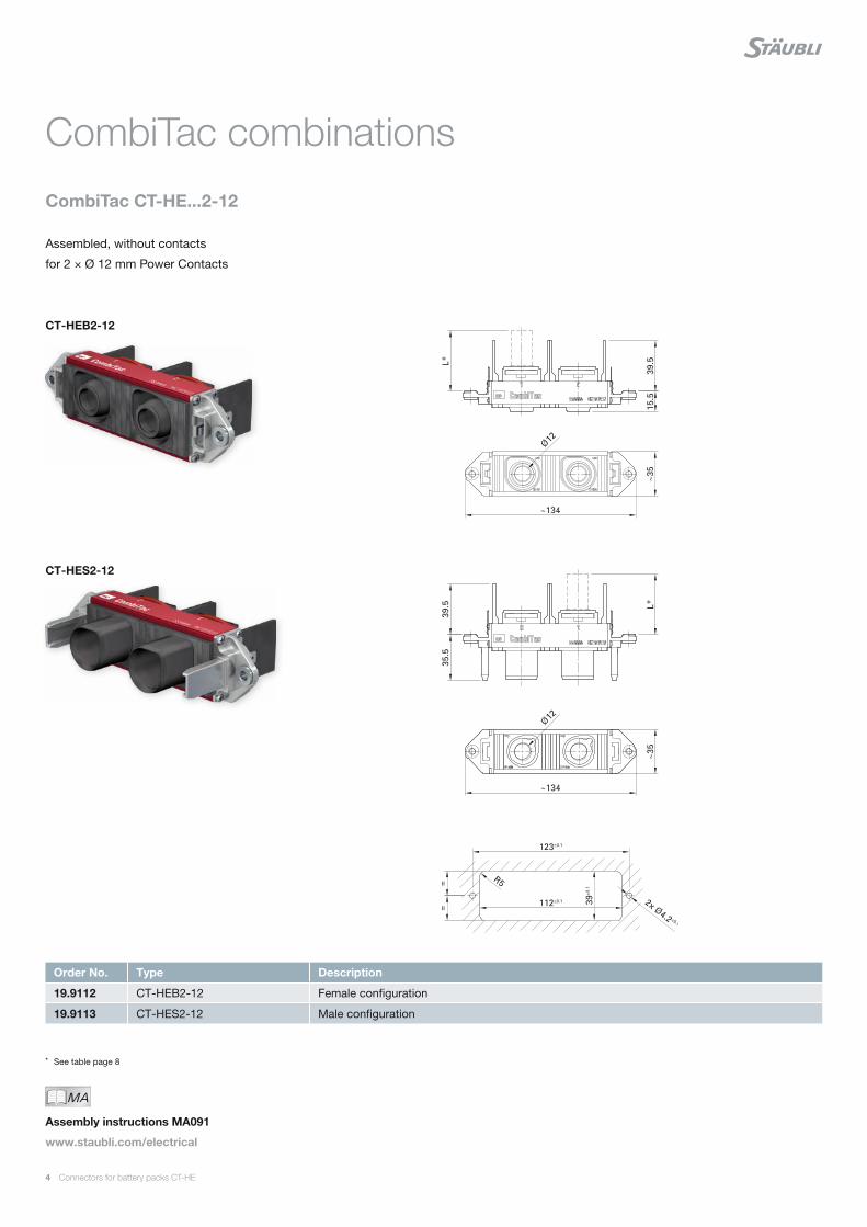
Order No. Type Description
19.9112 CT-HEB2-12 Female configuration
19.9113 CT-HES2-12 Male configuration
MAIch bin eine Montageanleitung.
Man sollte mich unbedingt le-
sen, bevor man das Produkt ver-
wendet! Ich beinhalte wertvolle
Hinweise zur korrekten Montage
und zum richtigen Einsatz des
Produktes. Im Moment ist die
Schrift zwar ein bischen klein,
aber später geht das dann ganz
gut zu lesen, da die MA dann
Assembly instructions MA091
www.staubli.com/electrical
* See table page 8
Assembled, without contacts
for 2 × Ø 12 mm Power Contacts
CombiTac combinations
CombiTac CT-HE...2-12
CT-HEB2-12
CT-HES2-12
Connectors for battery packs CT-HE 5
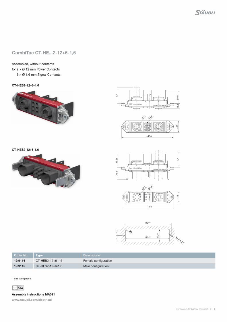
Order No. Type Description
19.9114 CT-HEB2-12+6-1,6 Female configuration
19.9115 CT-HES2-12+6-1,6 Male configuration
MAIch bin eine Montageanleitung.
Man sollte mich unbedingt le-
sen, bevor man das Produkt ver-
wendet! Ich beinhalte wertvolle
Hinweise zur korrekten Montage
und zum richtigen Einsatz des
Produktes. Im Moment ist die
Schrift zwar ein bischen klein,
aber später geht das dann ganz
gut zu lesen, da die MA dann
Assembly instructions MA091
www.staubli.com/electrical
* See table page 8
Assembled, without contacts
for 2 × Ø 12 mm Power Contacts
6 × Ø 1.6 mm Signal Contacts
CombiTac CT-HE...2-12+6-1,6
CT-HEB2-12+6-1,6
CT-HES2-12+6-1,6

6 Connectors for battery packs CT-HE
Order No. Type Description
19.9116 CT-HEB2-12+12-1,6 Female configuration
19.9117 CT-HES2-12+12-1,6 Male configuration
MAIch bin eine Montageanleitung.
Man sollte mich unbedingt le-
sen, bevor man das Produkt ver-
wendet! Ich beinhalte wertvolle
Hinweise zur korrekten Montage
und zum richtigen Einsatz des
Produktes. Im Moment ist die
Schrift zwar ein bischen klein,
aber später geht das dann ganz
gut zu lesen, da die MA dann
Assembly instructions MA091
www.staubli.com/electrical
* See table page 8
Assembled, without contacts
for 2 × Ø 12 mm Power Contacts
12 × Ø 1.6 mm Signal Contacts
CT-HEB2-12+12-1,6
CombiTac CT-HE...2-12+12-1,6
CT-HES2-12+12-1,6
Connectors for battery packs CT-HE 7
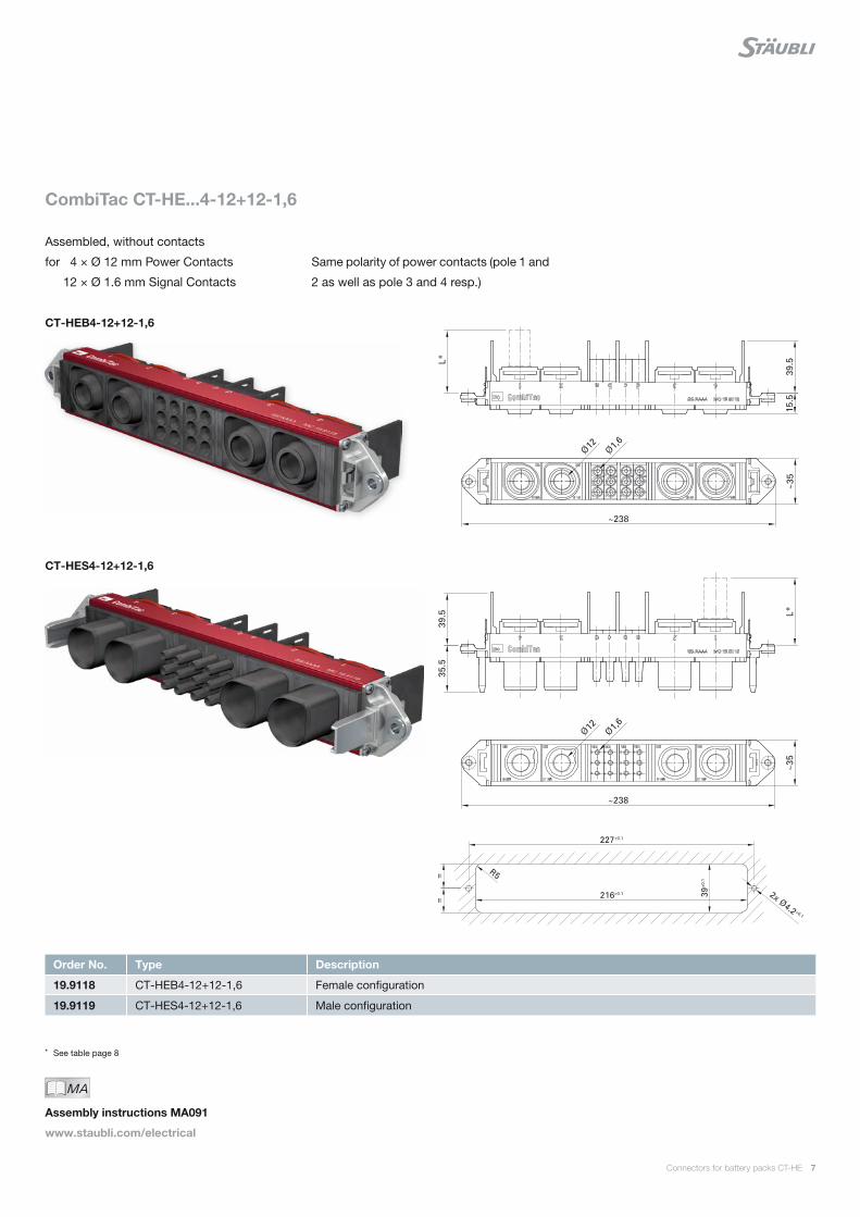
Order No. Type Description
19.9118 CT-HEB4-12+12-1,6 Female configuration
19.9119 CT-HES4-12+12-1,6 Male configuration
MAIch bin eine Montageanleitung.
Man sollte mich unbedingt le-
sen, bevor man das Produkt ver-
wendet! Ich beinhalte wertvolle
Hinweise zur korrekten Montage
und zum richtigen Einsatz des
Produktes. Im Moment ist die
Schrift zwar ein bischen klein,
aber später geht das dann ganz
gut zu lesen, da die MA dann
Assembly instructions MA091
www.staubli.com/electrical
* See table page 8
CT-HEB4-12+12-1,6
Assembled, without contacts
for 4 × Ø 12 mm Power Contacts
12 × Ø 1.6 mm Signal Contacts
CombiTac CT-HE...4-12+12-1,6
Same polarity of power contacts (pole 1 and
2 as well as pole 3 and 4 resp.)
CT-HES4-12+12-1,6
8 Connectors for battery packs CT-HE
1) Heating dT = 50 °K, see Derating-Diagram, page 112) See drawings on pages 4 to 7
Order No. Type Socket Pin Plating Conductor cross section
Rated current1) Max. depth2)
Type of termination
mm² A L (mm)
19.1007 19.1006
CTR-BP12/50 CTR-SP12/50
× ×
Ag
50 250 46
c
19.1009 19.1008
CTR-BP12/70 CTR-SP12/70
× ×
Ag
70 300 50
c
19.1011 19.1010
CTR-BP12/95 CTR-SP12/95
× ×
Ag
95 360 50
c
19.1013 19.1012
CTR-BP12/120 CTR-SP12/120
× ×
Ag
120 400 56
c
19.1015 19.1014
CTR-B12/M10 CTR-S12/M10
× ×
Ag
50 70 95 120
250 300 360 430
61
s
MAIch bin eine Montageanleitung.
Man sollte mich unbedingt le-
sen, bevor man das Produkt ver-
wendet! Ich beinhalte wertvolle
Hinweise zur korrekten Montage
und zum richtigen Einsatz des
Produktes. Im Moment ist die
Schrift zwar ein bischen klein,
aber später geht das dann ganz
gut zu lesen, da die MA dann
Assembly instructions MA091
www.staubli.com/electrical
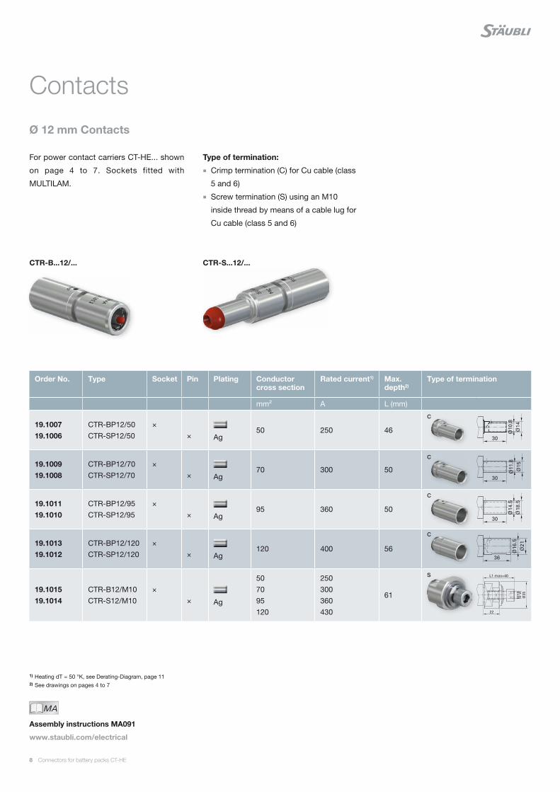
For power contact carriers CT-HE... shown
on page 4 to 7. Sockets fitted with
MULTILAM.
Ø 12 mm Contacts
Contacts
Type of termination:
■ Crimp termination (C) for Cu cable (class
5 and 6)
■ Screw termination (S) using an M10
inside thread by means of a cable lug for
Cu cable (class 5 and 6)
CTR-B...12/... CTR-S...12/...
Connectors for battery packs CT-HE 9
Order No. Type Socket Pin Plating Conductor cross section
Rated current Type of termination
mm² A
19.6777 19.6778
BP-C1,6/0,5-1,5 AU SP-C1,6/0,5-1,5 AU
× ×
Au
0.5 – 1.5 16
c
MAIch bin eine Montageanleitung.
Man sollte mich unbedingt le-
sen, bevor man das Produkt ver-
wendet! Ich beinhalte wertvolle
Hinweise zur korrekten Montage
und zum richtigen Einsatz des
Produktes. Im Moment ist die
Schrift zwar ein bischen klein,
aber später geht das dann ganz
gut zu lesen, da die MA dann
Assembly instructions MA091
www.staubli.com/electrical
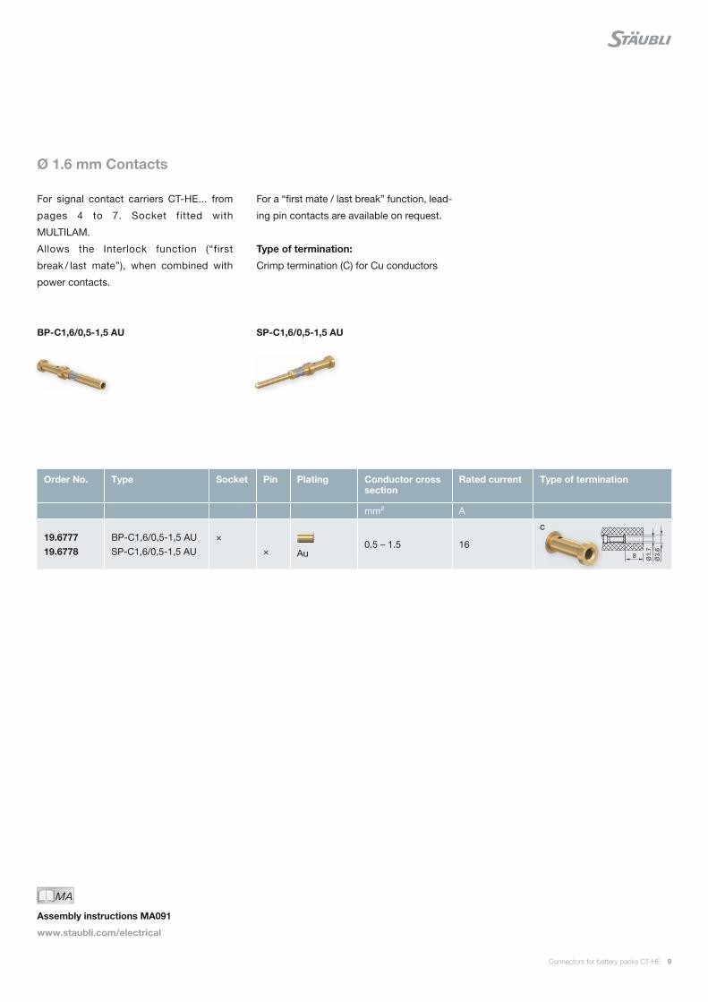
For signal contact carriers CT-HE... from
pages 4 to 7. Socket fitted with
MULTILAM.
Allows the Interlock function (“first
break / last mate”), when combined with
power contacts.
Ø 1.6 mm Contacts
For a “first mate / last break” function, lead-
ing pin contacts are available on request.
Type of termination:
Crimp termination (C) for Cu conductors
BP-C1,6/0,5-1,5 AU SP-C1,6/0,5-1,5 AU
10 Connectors for battery packs CT-HE
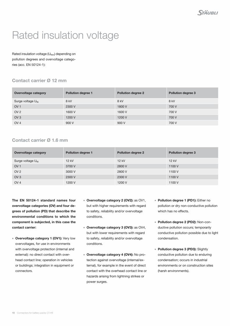
Rated insulation voltage
Rated insulation voltage (UNm) depending on
pollution degrees and overvoltage catego-
ries (acc. EN 50124-1):
Contact carrier Ø 12 mm
Overvoltage category Pollution degree 1 Pollution degree 2 Pollution degree 3
Surge voltage UNi 8 kV 8 kV 8 kV
OV 1 2300 V 1800 V 700 V
OV 2 1600 V 1600 V 700 V
OV 3 1200 V 1200 V 700 V
OV 4 900 V 900 V 700 V
Overvoltage category Pollution degree 1 Pollution degree 2 Pollution degree 3
Surge voltage UNi 12 kV 12 kV 12 kV
OV 1 3700 V 2800 V 1100 V
OV 2 3000 V 2800 V 1100 V
OV 3 2300 V 2300 V 1100 V
OV 4 1200 V 1200 V 1100 V
Contact carrier Ø 1.6 mm
The EN 50124-1 standard names four
overvoltage categories (OV) and four de-
grees of pollution (PD) that describe the
environmental conditions to which the
component is subjected, in this case the
contact carrier:
■ Overvoltage category 1 (OV1): Very low
overvoltages, for use in environments
with overvoltage protection (internal and
external): no direct contact with over-
head contact line; operation in vehicles
or buildings; integration in equipment or
connectors.
■ Overvoltage category 2 (OV2): as OV1,
but with higher requirements with regard
to safety, reliability and/or overvoltage
conditions.
■ Overvoltage category 3 (OV3): as OV4,
but with lower requirements with regard
to safety, reliability and/or overvoltage
conditions.
■ Overvoltage category 4 (OV4): No pro-
tection against overvoltage (internal/ex-
ternal), for example in the event of direct
contact with the overhead contact line or
hazards arising from lightning strikes or
power surges.
■ Pollution degree 1 (PD1): Either no
pollution or dry non-conductive pollution
which has no effects.
■ Pollution degree 2 (PD2): Non-con-
ductive pollution occurs; temporarily
conductive pollution possible due to light
condensation.
■ Pollution degree 3 (PD3): Slightly
conductive pollution due to enduring
condensation; occurs in industrial
environments or on construction sites
(harsh environments).
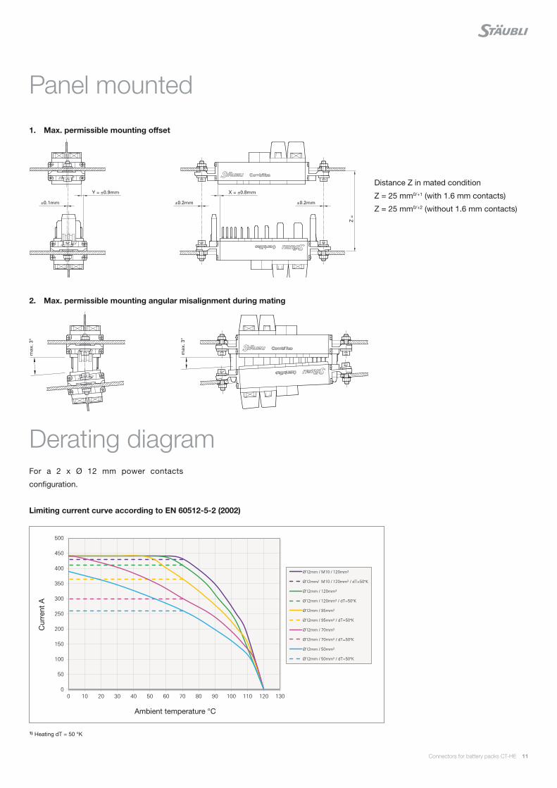
0
50
100
150
200
250
300
350
400
450
500
0 10 20 30 40 50 60 70 80 90 100 110 120 130
Ø12mm / M10 / 120mm²
Ø12mm/ M10 / 120mm² / dT=50°K
Ø12mm / 120mm²
Ø12mm / 120mm² / dT=50°K
Ø12mm / 95mm²
Ø12mm / 95mm² / dT=50°K
Ø12mm / 70mm²
Ø12mm / 70mm² / dT=50°K
Ø12mm / 50mm²
Ø12mm / 50mm² / dT=50°K
Connectors for battery packs CT-HE 11
Panel mounted
Derating diagram
Distance Z in mated condition
Z = 25 mm0/+1 (with 1.6 mm contacts)
Z = 25 mm0/+2 (without 1.6 mm contacts)
For a 2 x Ø 12 mm power contacts
configuration.
1) Heating dT = 50 °K
1. Max. permissible mounting offset
2. Max. permissible mounting angular misalignment during mating
Limiting current curve according to EN 60512-5-2 (2002)
Cur
rent
A
Ambient temperature °C

Global presenceof the Stäubli Group
Stäubli Units Agents
Staubli is a trademark of Stäubli International AG, registered in Switzerland and other countries.We reserve the right to modify product specifi cations without prior notice. © Stäubli [email protected] | Photo credits: Stäubli
www.staubli.com
IS R
ai C
T-H
E
1101
4033
-en
B
11.2
019