Embed Size (px)
Citation preview

MAXCONNEUROPEEdlingerstrasse 3D-81543 Munich/MünchenTel: 49 (0) 89-65 11 30 88Fax: 49 (0) 89-65 11 30 87E-Mail: [email protected]: eucon-elektronik.com
Connectors and Custom Cablesfor Worldwide Applications

MAXCONN, INC. - 2151 DEL FRANCO STREETo SAN JOSE, CALIFORNIA 95131 - 408-435-5050,, FAX: 408-435-8377MAXCONN EUROPE. - Edlingerstr. 3 - D-81543 Munich/München Tel: 49 (0) 89-65 11 30 88, Fax: 49 (0) 89-65 11 30 88
E-Mail: [email protected] - Web: http://www.eucon-elektronik.com
Please visit also our WebSite http://www.maxconn.com - or eucon-elektronik.com for Europe
"Globally Connecting today's
world with tomorrowsTechnology!"
Maxconn Inc. USA4255 Business Center DriveFremont, California 94538Tel: 510-979-0979Fax: 510-360-1599E-mail:[email protected]
Maxconn Cable & Connector Ltd.Taiwan Branch4th Floor, 3 Lane Si Wei, Chung Cheng RoadHsin Tien CityTaipei Hsein, Taiwan R.O.C.Tel: 886-2-2218-8336Fax: 886-2-2218-2370E-mail: [email protected]
Maxconn EuropeEdlingerstrasse 3D-81543Munchen GermanyTel: 089-6-511-3088Fax: 089-6-511-3087E-mail:[email protected]
About News Email Catalog Comments
Product Distributors | Sales RepresentativesRequest For Sample/Quote Form
Search For:
Boolean: AND Case Insensitive
Search! Zurücksetzen
©Copyright 1997 by Maxconn Incorporated. All rights reserved.4255 Business Center Drive, Fremont, CA 94538
Telephone: (510) 979-0979 | Fax: (510) 360-1599 | http://www.maxconn.com

TABLE OF CONTENTS
Page
Section I - D-Subminiature ConnectorsMRS Series - Right Angle Termination .318 Footprint 1-2MRSF Series - Right Angle Termination Filtered Capacitor Contact 1-4MRL Series - Right Angle Termination .590 Footprint 1-6MRH Series - High Density, Right Angle Termination .350 Footprint 1-8MST Series - Dual Port Connectors 9/9, 15115, 25/25, 37/37 1-10MSD Series - Slimline Right Angle. 197 (5 mm) Footprints 1-16MSMD Series - Surface Mount, Right Angle 1-18MSMDH Series - Surface Mount, High Density, Right Angle 1-19MD Series - Vertical Pin and Solder Cup Termination 1-20MDH Series - High Density Vertical Pin and Solder Cup Termination 1-22MC Series - Housing for Crimp Contacts 1-24MCH Series - High Density Housing for Crimp Contacts 1-26Hoods-Plastic, Metal - Accessories and Hardware 1-28Slide Lock Assembly - Accessories and Hardware 1-29
Section 2 - Modular Jack ConnectorsMJDS Series - Stacked Modular Jacks (27.80 mm) 8 to 12 Ports, Shielded and Non-Shielded 2-2MJDS-LG5 Series - Stacked Modular Jacks 2 to 16 Ports, Shielded 2-4MJFS Series - Filtered Transformer, Shielded, Standard PCB Footprint 2-6MJH Series - Low Profile (.498 Height) Non-Shielded, Partially Shielded 2-10MJH-R Series - Single Cavity, Standard Height, Non-Shielded, Shielded 2-11MJH-V Series - Vertical, Non-Shielded, Shielded 2-13MJH-G Series - Non-Shielded, Shielded 2 to 12 Ports 2-14MJL Series - Ultra-Low Profile, (.453 Height) Non-Shielded 2-16MJL-G Series - Gang Ultra-Low Profile Height, Non-Shielded, Shielded 2-17MJLS Series - Ultra-Low Profile, (.460 Height) Shielded 2-18MJLSS Series - Ultra-Low Profile (.460 Height) Surface Mount, Shielded, Non-Shielded 2-20MJH-C Series - RJII /RJ45 Combination, Low Profile, .543 High 2-22MJA Series - Right Angle, PC Mount 2-23MJB Series - Right Angle, PC Mount 2-24MJG Series - 6 or 8 Position, Right Angle, Ganged, Non-Shielded 2-25MJG Series - 6 or 8 Position, Vertical, Ganged, Non-Shielded 2-26MJF Series - Right Angle, PC Mount 2-27MJM Series - Right Angle, PC Mount 2-28MJP Series - Vertical, PC Mount 2-29MCJ-P Series - IDC Panel Jack 2-30MJC-88 Series - Modular Jack Coupler Non-Shielded, Shielded 2-31MP Series - Non-Shielded, Shielded 2-32MP8B Series - Cable Boots with and without Latch Protectors 2-34MP Series - Male Cable Assembly 2-35
Section 3 - Flat Flex Circuit ConnectorsMFPC Series - 1.00mm Right Angle Surface Mount, Vertical Contact 3-2
Section 4 - Ribbon Connectors (no longer carried by Maxconn)
Section 5 - Back Plane Connectors (no longer carried by Maxconn)
Section 6 - Euro DIN Connectors (no longer carried by Maxconn)
MAXCONN, INC. - 2151 DEL FRANCO STREETo SAN JOSE, CALIFORNIA 95131 - 408-435-5050,, FAX: 408-435-8377MAXCONN EUROPE. - Edlingerstr. 3 - D-81543 Munich/München Tel: 49 (0) 89-65 11 30 88, Fax: 49 (0) 89-65 11 30 88
E-Mail: [email protected] - Web: http://www.eucon-elektronik.com

Section 7 - Headers5210, 5220 Series - 0.05 (1.27 mm) Centers, Single and Dual Row 7-25S210, 5S220 Series - 0.05 (1.27 mm) Centers, Surface Mount, Single and Dual Row 7-35410, 5420 Series - 0.05 (1.27 mm) Centers Single and Dual Row 7-45S410, 5S420 Series - 0.05 (1.27 mm) Centers, Surface Mount, Single and Dual Row 7-52M210, 2M220 Series - 0.079 (2 mm) Centers Single and Dual Row 7-62MS220 Series - 0.079 (2mm) Centers, Surface Mount, Dual Row 7-72M21013S, 2M22013S Series - 0.079 (2mm) Centers Single and Dual Row 7-82M410, 2M420 Series - 0.079 (2 mm) Centers Single and Dual Row 7-92MS420 Series - 0.079 (2 mm) Surface Mount, Dual Row, 6 to 60 Positions 7-10210, 220, 230 Series - 0.1 (2.54 mm) Centers Single, Dual and Three Row 7-1121013S, 220BS Series - 0.1 (2.54 mm) Centers Single and Dual Row 7-13410, 420 Series - 0.1 (2.54 mm.) Centers Single and Dual Row 7-14EH Series - 0.1 (2.54 mm.) Centers Dual Row 7-15SH Series - 0.1 (2.54 mm) Centers Dual Row 7-16320 Series - 0.1 (2.54 mm) Centers Dual Row 7-17S100, S200, S300 Series - 0.1 (2.54 mm) Centers 7-18S9 Series - 0.1 (2.54 mm) Centers 7-19
Section 8 - Sockets (no longer carried by Maxconn)
Section 9 - Mini DIN ConnectorsMMDF Series - Circular Non-Shielded, Shielded, and Fully Shielded 9-2MMDS Series - Circular, Shielded and Fully Shielded with Switch 9-4MMDV Series - Circular Connectors Vertical Type, 3 to 8 Contacts 9-5MMDV Series - Circular Connectors Vertical Type, 9 Contacts 9-6MMDM Series - Shielded Male Plug 9-7MMDFS Series - Stacked, 4 Positions, Top and Bottom 9-8MMDFS Series - Stacked, 6 Positions, Top and Bottom 9-9MMDFS Series - Stacked, 8 Positions, Top and Bottom 9-10
Section 10 - BNC ConnectorsMBNC Series - Right Angle, Vertical, Surface Mount Receptical withTerminating Resistors and Filtering Capacitors 10-2MBNC Series - Right Angle, Vertical, Terminators, and Filtered Board Level Connectors 10-5MBNC-AT Series - Auto-Termination SMT Compatible PCB Mount Double Female Connector 10-6MNF Series - Right Angle, F-Connector PCB Mount Receptical 10-8MBNC Series - BNC Connector Right Angle PCB Mount Receptical 10-9MBNC Series - BNC Connector Right Angle PCB Mount Receptical with LED Indicator 10-10MNF Series - F-Connector, Right Angle, PCB Mount Receptical 10-11MNF Series - F-Connector, Right Angle, PCB Mount Receptical with LED 10-12
Section 11 - Smart Card ConnectorMSC Series - Excepts ISO 7818 IC Card 11-2
Section 12 - Universal Serial BusMUSB Series - Right Angle Termination, Single and Stacked 12-2MIEEE-P1394 Series - Fire Wire Connector 12-5
Section 13 - Insulation Displacement Connectors (no longer carried by Maxconn)
Section 14 - Circular DIN Connectors (no longer carried by Maxconn)
Section 15 - Power Connectors (no longer carried by Maxconn)
Section 16 - Custom CablesMCBL Series 16-2
MAXCONN, INC. - 2151 DEL FRANCO STREETo SAN JOSE, CALIFORNIA 95131 - 408-435-5050,, FAX: 408-435-8377MAXCONN EUROPE. - Edlingerstr. 3 - D-81543 Munich/München Tel: 49 (0) 89-65 11 30 88, Fax: 49 (0) 89-65 11 30 88
E-Mail: [email protected] - Web: http://www.eucon-elektronik.com

D-SubminiatureConnectors
MRS Series - Right Angle Termination .318 Footprint 1-2MRSF Series - Right Angle Termination Filtered Capacitor Contact 1-4MRL Series - Right Angle Termination .590 Footprint 1-6MRH Series - High Density, Right Angle Termination .350 Footprint 1-8MST Series - Dual Port Connectors 9/9, 15/15, 25/25, 37/37 1-10MSD Series - Slimline Right Angle. 197 (5mm) Footprints 1-16
MSMD Series - Surface Mount, Right Angle 1-18MSMDH Series - Surface Mount, High Density, Right Angle 1-19MD Series - Vertical Pin and Solder Cup Termination 1-20MDH Series - High Density Vertical Pin and Solder Cup Termination 1-22MC Series - Housing for Crimp Contacts 1-24MCH Series - High Density Housing for Crimp Contacts 1-26Hoods-Plastic, Metal - Accessories and Hardware 1-28Slide Lock Assembly - Accessories and Hardware 1-29
MAXCONN, INC. - 2151 DEL FRANCO STREETo SAN JOSE, CALIFORNIA 95131 - 408-435-5050,, FAX: 408-435-8377MAXCONN EUROPE. - Edlingerstr. 3 - D-81543 Munich/München Tel: 49 (0) 89-65 11 30 88, Fax: 49 (0) 89-65 11 30 88
E-Mail: [email protected] - Web: http://www.eucon-elektronik.com
D-SUBMINIATURE CONNECTORS
MAXCONN, INC. • 2151 DEL FRANCO STREET • SAN JOSE, CALIFORNIA 95131 • 408-435-5050 • FAX: 408-435-83771-2
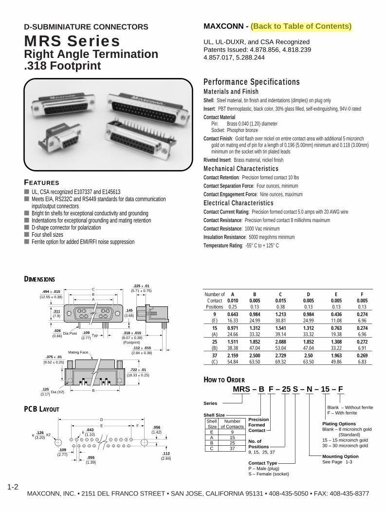
MRS SeriesRight Angle Termination.318 Footprint
Performance SpecificationsMaterials and FinishShell : Steel material, tin finish and indentations (dimples) on plug onlyInsert : PBT thermoplastic, black color, 30% glass filled, self-extinguishing, 94V-0 ratedContact Material
Pin: Brass 0.040 (1.20) diameterSocket: Phosphor bronze
Contact Finish : Gold flash over nickel on entire contact area with additional 5 microinch gold on mating end of pin for a length of 0.196 (5.00mm) minimum and 0.118 (3.00mm) minimum on the socket with tin plated leads
Riveted Insert : Brass material, nickel finish
Mechanical CharacteristicsContact Retention : Precision formed contact 10 lbsContact Separation Force : Four ounces, minimumContact Engagement Force : Nine ounces, maximum
Electrical CharacteristicsContact Current Rating : Precision formed contact 5.0 amps with 20 AWG wireContact Resistance : Precision formed contact 8 milliohms maximumContact Resistance : 1000 Vac minimumInsulation Resistance : 5000 megohms minimumTemperature Rating : -55° C to + 125° C
Number of A B C D E F Contact 0.010 0.005 0.015 0.005 0.005 0.005
Positions 0.25 0.13 0.38 0.13 0.13 0.13
9 0.643 0.984 1.213 0.984 0.436 0.274(E) 16.33 24.99 30.81 24.99 11.08 6.96
15 0.971 1.312 1.541 1.312 0.763 0.274(A) 24.66 33.32 39.14 33.32 19.38 6.96
25 1.511 1.852 2.088 1.852 1.308 0.272(B) 38.38 47.04 53.04 47.04 33.22 6.91
37 2.159 2.500 2.729 2.50 1.963 0.269(C) 54.84 63.50 69.32 63.50 49.86 6.83
.311(7.9)
CBA
.494 ± .015(12.55 ± 0.38)
.026(0.66)
Dia Post .109(2.77)
Typ
.145(3.68)
Mating Face.375 ± .01
(9.52 ± 0.25)
.125(3.17)
B
.722 ± .01(18.33 ± 0.25)
.225 ± .01(5.71 ± 0.75)
.318 ± .015(8.07 ± 0.38)
Dia (X2)
.112 ± .015(2.84 ± 0.38)
(Footprint)
FEATURES■ UL, CSA recognized E107337 and E145613■ Meets EIA, RS232C and RS449 standards for data communication
input/output connectors■ Bright tin shells for exceptional conductivity and grounding■ Indentations for exceptional grounding and mating retention■ D-shape connector for polarization■ Four shell sizes■ Ferrite option for added EMI/RFI noise suppression
DIMENSIONS
HOW TO ORDER
E
D
F
f.043
(1.10)
.109(2.77)
.055(1.39)
f.126
(3.20)X2
.056(1.42)
.112(2.84)
PCB LAYOUT
MRS – B F – 25 S – N – 15 – F
Series
Shell SizeShell NumberSize of ContactsE 9A 15B 25C 37
Blank – Without ferriteF – With ferrite
Plating OptionsBlank – 8 microinch gold
(Standard)15 – 15 microinch gold30 – 30 microinch gold
Mounting OptionSee Page 1-3
PrecisionFormedContact
No. ofPositions9, 15, 25, 37
Contact TypeP – Male (plug)S – Female (socket)
UL, UL-DUXR, and CSA RecognizedPatents Issued: 4.878.856, 4.818.2394.857.017, 5.288.244
MAXCONN - (Back to Table of Contents)

MountingHole
JackScrew
.375(9.53)
Bracket
.318Footprint
MRS SeriesRight Angle T ermination .318 Footprint
Mounting Options
Option M0.375 mounting flange hole dimension, with0.130 diameter non-threaded mounting holes,and with riveted threaded inserts.
Option MJIncludes Option M and with jack screwsassembled to connector.
GroundingBracket
.318Footprint
GroundingBracket
.375(9.53)
4-40 ThreadedRiveted Insert
.110(2.79)
.140(3.56)
GroundingBracket
Option NWith grounding brackets (locking-type) andwith riveted threaded inserts.
Option NJIncludes Option N and with jack screwsassembled to connector.
4-40 ThreadedRiveted Insert with
Jack Screw
(
.375(9.53)
Option NSWith grounding brackets (locking-type) andwith round 4-40 fixed standoff.
Option OWith grounding straps, with 0.125 diameternon-threaded mounting holes, and withriveted threaded inserts.
Option OJIncludes Option O and with round 4-40 fixedstandoff. Mounting
Hole
4-40 ThreadedRiveted Insert
with Jack Screw
.375(9.53)
.318Footprint
GroundingBracket
Round 4-40Fixed Standoff
.236(6.00)
Option OSWith grounding straps, with 0.125 diameternon-threaded mounting holes, and withround 4-40 fixed standoff.
MAXCONN, INC. • 2151 DEL FRANCO STREET • SAN JOSE, CALIFORNIA 95131 • 408-435-5050 • FAX: 408-435-8377
MAXCONN - (Back to Table of Contents)D-SUBMINIATURE CONNECTORS
.110(2.79)
GroundingBracket
GroundingBracket
.318Footprint
GroundingBracket
Rounded 4-40 Fixed Standoff
.140(3.56)
.236
.375(9.53)
1-3
Option M Option MJ
Option N Option NJ
Option NS
Option O Option OJ
Option OS
GroundingStrap
.318Footprint
MountingHole
4-40 ThreadedRiveted Insert
.375(9.53)

MAXCONN - (Back to Table of Contents)
MAXCONN, INC. • 2151 DEL FRANCO STREET • SAN JOSE, CALIFORNIA 95131 • 408-435-5050 • FAX: 408-435-8377
D-SUBMINIATURE CONNECTORS
1-4
MRSF SeriesRight Angle T erminationFiltered Capacitor Contact
Performance SpecificationsMaterials and FinishShell : Steel material, tin finish and indentations (dimples) on plug onlyInsert : PBT thermoplastic, 30% glass filled, self-extinguishing, 94V-0 ratedContact Material
Pin: Copper alloy, gold platedSocket: Copper alloy, gold plated
Contact Finish : Gold flash over nickel on entire contact, 30 microinch gold on mating end of pin for a length of 0.196 (5.00mm) minimum and 0.118 (3.00mm) minimum on the socket (standard)
Riveted Insert : Brass material, nickel finishBracket and Board Lock : Brass material, nickel finish
Mechanical CharacteristicsContact Retention : Precision formed contact 10 lbsContact Separation Force : Maximum 0.8N per pair of mating contactsContact Engagement Force : Maximum 0.8N per pair of mating contacts
Electrical CharacteristicsMating Cycles : 500 minimumsContact Current Rating : 5.0 amps or 7.5 amps contactOperating Voltage : 250VTest Voltage Between Contacts : 1000 50/60 Hz, 1 min. Resistance per Based Contact : ²2.7m ohm/A (MIL-C-24308)Test Voltage Between Shell and Contact : 1000 Vac 50/60 Hz minimumInsulation Resistance : 5000 megohms minimumTemperature Rating : -67° F to + 311° F
Number of A B C D E F Contact 0.015 0.005 0.010 0.005 0.005 0.005
Positions 0.38 0.13 0.25 0.13 0.13 0.13
9 1.213 0.984 0.643 0.984 0.436 0.274(E) 30.81 24.99 16.33 24.99 11.08 6.96
15 1.541 1.312 0.971 1.312 0.763 0.274(A) 39.14 33.32 24.66 33.32 19.38 6.96
25 2.088 1.852 1.511 1.852 1.308 0.272(B) 53.04 47.04 38.38 47.04 33.32 6.91
37 2.729 2.500 2.159 2.500 1.963 0.269(C) 69.32 63.50 54.84 63.50 49.86 6.83
C
B
A
0.100(2.54)
0.494 ± 0.015(12.55 ± 0.38) 0.318
(8.07)
0.109(2.77)DIA.
0.022(0.57)
0.311(7.90)
FEATURES■ UL and CSA recognized E107337 and E145613■ Meets EIA, RS232C and RS449 standards for data communication
input/output connectors■ Bright tin shells for exceptional conductivity and grounding■ Indentations for exceptional grounding and mating retention■ D-shape connector for polarization■ Four shell sizes■ Ferrite option for added EMI/RFI noise suppression
DIMENSIONS
HOW TO ORDER
MRSF – X F – X X – –XXXX
Series
Shell SizeShell SizeE—9A—15B—25C—37
Board Mounting OptionBRBL -W/4-40 Insert
Mtg Bracket and Board LockBRPL -W/4-40 Insert
Mtg Bracket, Face Plateand Board Lock
FerriteF – Ferrite BlockCapacitance1— 47pF 4 — 470pF2 — 220pF 5 — 1000pF3 — 330pF 6 — 2000pF
PrecisionFormedContact
NumberofPositions9, 15, 25, 37
ContactTypeP—Male (plug)S—Female (socket)
UL, UL-DUXR, and CSA RecognizedPatents Issued: 4.878.856, 4.818.2394.857.017, 5.288.244

ED
0.043(3.20)
DIA. 0.112(2.845)
0.056(1.422)F
0.043(3.20)
DIA.
0.109(2.769)0.055(1.39)
PCB LAYOUT (TOP VIEW)
MAXCONN - (Back to Table of Contents)
MAXCONN, INC. • 2151 DEL FRANCO STREET • SAN JOSE, CALIFORNIA 95131 • 408-435-5050 • FAX: 408-435-8377
D-SUBMINIATURE CONNECTORS
1-5
MRSF SeriesRight Angle T erminationFiltered Capacitor Contact
Options
Option BRPL Without FerriteShown with 4–40 insert, face plate, mounting bracket and board
Option BRPL With FerriteShown with 4–40 insert, face plate, mounting bracket and board
Option BRBL TypeShown with 4–40 insert, mounting bracket and board
1.312(33.32)
0.853(21.68)
4-40UNC-2B
0.452(11.48)
0.297(7.55)
1.312(33.32)
1.312(33.32)
4-40UNC-2B
Face Plate Face Plate
0.452(11.48)
1.312(33.32)
1.312(33.32)
4-40UNC-2B
FacePlate Face PlateFerrite Block
0.452(11.48)

D-SUBMINIATURE CONNECTORS MAXCONN - (Back to Table of Contents)
MAXCONN, INC. • 2151 DEL FRANCO STREET • SAN JOSE, CALIFORNIA 95131 • 408-435-5050 • FAX: 408-435-8377
D-SUBMINIATURE CONNECTORS
1-6
MRL SeriesRight Angle Termination.590 Footprint
Performance SpecificationsMaterials and FinishShell : Steel material, tin finish and indentations (dimples) on plug onlyInsert : PBT thermoplastic, black color, 30% glass filled, self-extinguishing, 94V-0 ratedContact Material
Pin: Brass 0.040 (1.20) diameterSocket: Phosphor bronze
Contact Finish : Gold flash over nickel on entire contact area with additional 5 microinch gold on mating end of pin for a length of 0.196 (5.00mm) minimum and 0.118 (3.00mm) minimum on the socket
Riveted Insert : Brass material, nickel finish
Mechanical CharacteristicsContact Retention : Precision formed contact 10 lbsContact Separation Force : Four ounces, minimumContact Engagement Force: Nine ounces, maximum
Electrical CharacteristicsContact Current Rating : Precision formed contact 5.0 amps with 20 AWG wireContact Resistance : Precision formed contact 8 milliohms maximumContact Resistance : 1000 Vac minimumInsulation Resistance : 5000 megohms minimumTemperature Rating : -55° C to + 125° C
Number of A B C D E F Contact 0.010 0.005 0.015 0.005 0.005 0.005
Positions 0.25 0.13 0.38 0.13 0.13 0.13
9 0.643 0.984 1.213 0.984 0.436 0.274(E) 16.33 24.99 30.81 24.99 11.08 6.96
15 0.971 1.312 1.541 1.312 0.763 0.274(A) 24.66 33.32 39.14 33.32 19.38 6.96
25 1.511 1.852 2.088 1.852 1.308 0.272(B) 38.38 47.04 53.04 47.04 33.22 6.91
37 2.159 2.500 2.729 2.500 1.963 0.269(C) 54.84 63.50 69.32 63.50 49.86 6.83
.112 ± .015(2.84 ± 0.38)
.311(7.9)
CBA
.494 ± .015(12.55 ± 0.38)
.026(0.66)
Dia Post .109(2.77)
Typ
.110(2.79)
Mating Face
.125(3.17)
B
.990 ± .01(25.14 ± 0.25)
.225 ± .01(5.71 ± 0.75)
.590 ± .015(14.99 ± 0.38)
(Footprint)
See MountingOptions
Dia (X2)
FEATURES■ UL and CSA recognized E107337 and E145613■ Meets EIA, RS232C and RS449 standards for data communication
input/output connectors■ Bright tin shells for exceptional conductivity and grounding■ Indentations for exceptional grounding and mating retention■ D-shape connector for polarization■ Four shell sizes
DIMENSIONS
HOW TO ORDER
PCB LAYOUTContact factory for PCB layout options.
MRL – B F – 25 S – P – 15
Series
Shell SizeShell NumberSize of ContactsE 9A 15B 25C 37
Plating OptionsBlank – 8 microinch gold
(Standard)15 – 15 microinch gold30 – 30 microinch gold
Mounting OptionSee Page 1-5
Contact TypeP – Male (plug)S – Female (socket)
PrecisionFormedContact
No. ofPositions9, 15, 25, 37
UL, UL-DUXR, and CSA RecognizedPatents Issued: 4.878.856, 4.818.2394.857.017, 5.288.244
MAXCONN - (Back to Table of Contents)
MAXCONN, INC. • 2151 DEL FRANCO STREET • SAN JOSE, CALIFORNIA 95131 • 408-435-5050 • FAX: 408-435-8377
D-SUBMINIATURE CONNECTORS
1-7
.590Footprint
GroundingBracket
4-40 ThreadedRiveted Insert
.110(2.79)
.140(3.56)
GroundingBracket
GroundingBracket
.315(8.00)
MountingHole
.630(16.00)
4-40 Threaded RivetedInsert with Jack Screw
MountingHole
GroundingBracket
.315(8.00)
.630(16.00)
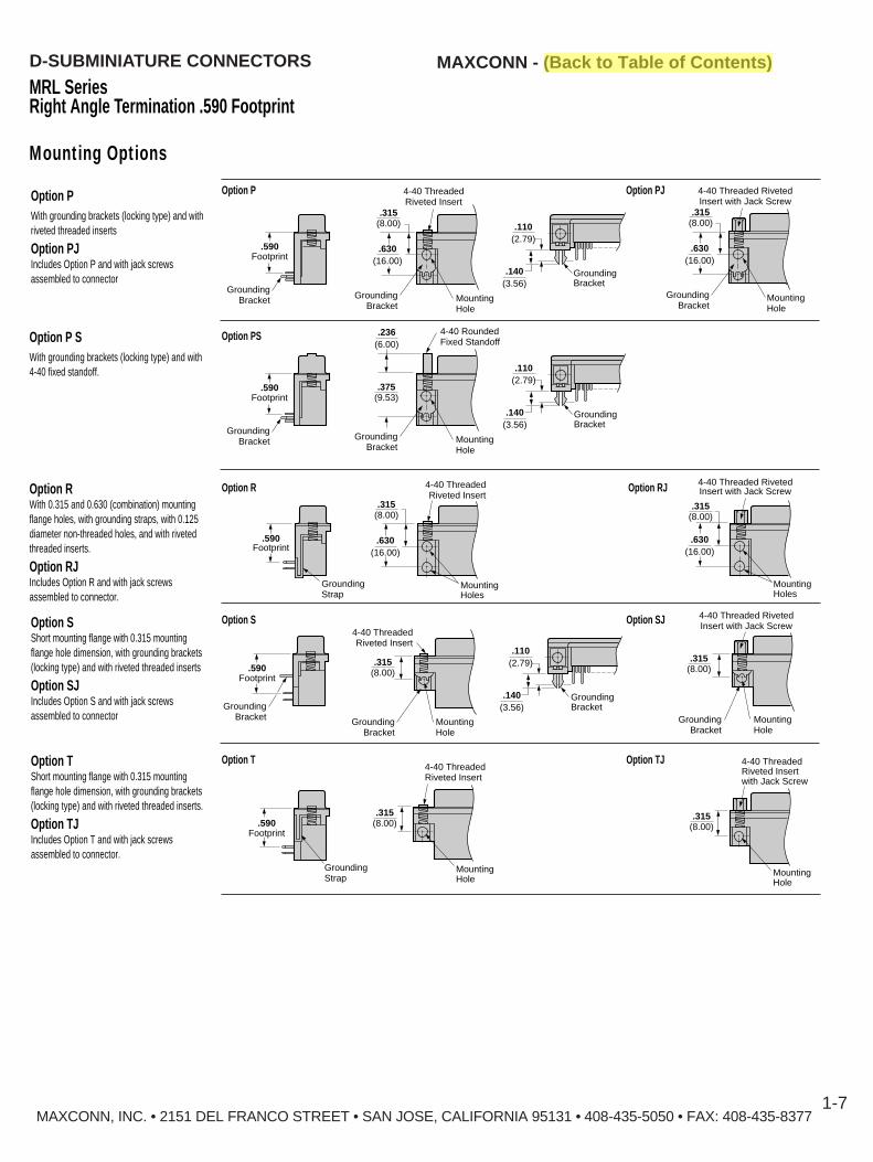
MRL SeriesRight Angle T ermination .590 Footprint
Mounting Options
Option PWith grounding brackets (locking type) and withriveted threaded inserts
Option PJIncludes Option P and with jack screwsassembled to connector
Option RWith 0.315 and 0.630 (combination) mountingflange holes, with grounding straps, with 0.125diameter non-threaded holes, and with rivetedthreaded inserts.
Option RJIncludes Option R and with jack screwsassembled to connector.
4-40 ThreadedRiveted Insert
GroundingStrap
MountingHoles
.590Footprint
.315(8.00)
.630(16.00)
4-40 Threaded RivetedInsert with Jack Screw
ding MountingHoles
.315(8.00)
.630(16.00)
.590Footprint
GroundingBracket
Option SShort mounting flange with 0.315 mountingflange hole dimension, with grounding brackets(locking type) and with riveted threaded inserts
Option SJIncludes Option S and with jack screwsassembled to connector Mounting
Hole
4-40 Threaded RivetedInsert with Jack Screw
GroundingBracket
.315(8.00)
GroundingStrap
.590Footprint
Option TShort mounting flange with 0.315 mountingflange hole dimension, with grounding brackets(locking type) and with riveted threaded inserts.
Option TJIncludes Option T and with jack screwsassembled to connector.
4-40 ThreadedRiveted Insertwith Jack Screw
MountingHole
.315(8.00)
Option P Option PJ
Option R Option RJ
Option S Option SJ
Option T Option TJ
Option P SWith grounding brackets (locking type) and with4-40 fixed standoff.
Option PS
.590Footprint
GroundingBracket
4-40 RoundedFixed Standoff
.110(2.79)
.236(6.00)
.140(3.56)
GroundingBracket
GroundingBracket
MountingHole
.375(9.53)
MountingHole
4-40 ThreadedRiveted Insert
.110(2.79)
.140(3.56)
GroundingBracket
GroundingBracket
.315(8.00)
4-40 ThreadedRiveted Insert
MountingHole
.315(8.00)

MRH SeriesHigh-Density , Right Angle Termination .350 Footprint
Performance SpecificationsMaterials and FinishShell : Steel material, tin finish and indentations (dimples) on plug onlyInsert : PBT thermoplastic, black color, 30% glass filled, self-extinguishing, 94V-0 ratedContact Material
Pin: Brass 0.040 (1.20) diameterSocket: Phosphor bronze
Contact Finish : Gold flash over nickel on entire contact area with additional 5 microinch gold on mating end of pin for a length of 0.196 (5.00mm) minimum and 0.118 (3.00mm) minimum on the socket
Riveted Insert : Brass material, nickel finish
Mechanical CharacteristicsContact Retention : Precision formed contact 10 lbsContact Separation Force : Four ounces, minimumContact Engagement Force: Nine ounces, maximum
Electrical CharacteristicsContact Current Rating : 5.0 amps with 20 AWG wireContact Resistance : 8 milliohms maximumContact Resistance : 1000 Vac minimumInsulation Resistance : 5000 megohms minimumTemperature Rating : -55° C to + 125° C
FEATURES■ ULand CSA recognized E107337 and E145613■ Meets EIA, RS232C and RS449 standards for data communication
input/output connectors■ Bright tin shells for exceptional conductivity and grounding■ Indentations for exceptional grounding and mating retention■ D-shape connector for polarization■ Four shell sizes■ Ferrite option for added EMI/RFI noise suppression
CBA
.350 ± .01(8.89 ± 0.25)
.236 ± .004(6.0 ± 0.10)
.100 ± .01(2.54 ± 0.25)
.311 ± .015(7.90 ± 0.38)
.024 ± .030(0.60 ± 0.76)
.157 ± .01(4.00 ± 0.25)
.450 ± .010(11.43 ± 0.25)
.984 ± .005(24.99 ± .013)
.875 ± .015(22.22 ± 0.38)
.494 ± .015(12.55 ± 0.38)
DIMENSIONS
.100(2.54)f
.125(3.18)
X2
f.043
(1.10).100
(2.54)
FE
D
G
PCB LAYOUT (TOP VIEW)
Number of A B C D E F GContact 0.010 0.005 0.015 0.005 0.005 0.005 0.005
Positions 0.25 0.13 0.38 0.13 0.13 0.13 0.13
15 0.643 0.984 1.213 0.984 0.492 0.215 0.090(E) 16.33 24.99 30.81 24.99 12.50 5.45 2.29
26 0.971 1.312 1.541 1.312 0.656 0.385 0.090(A) 24.66 33.32 39.14 33.32 16.66 9.78 2.29
44 1.511 1.852 2.088 1.852 0.926 0.655 0.090(B) 38.38 47.04 53.04 47.04 23.52 16.64 2.29
62 2.169 2.500 2.729 2.500 1.250 0.974 0.095(C) 54.84 63.50 69.23 63.50 31.75 24.75 2.41
MAXCONN, INC. • 2151 DEL FRANCO STREET • SAN JOSE, CALIFORNIA 95131 • 408-435-5050 • FAX: 408-435-8377
MAXCONN - (Back to Table of Contents)D-SUBMINIATURE CONNECTORS
1-8
DIMENSIONS – MALE
DIMENSIONS – FEMALE
Number of A B C D E F GContact 0.010 0.005 0.015 0.005 0.005 0.005 0.005
Positions 0.25 0.13 0.38 0.13 0.13 0.13 0.13
15 0.656 0.984 1.213 0.984 0.492 0.215 0.090(E) 18.92 24.99 30.81 24.99 12.50 5.45 2.29
26 0.994 1.312 1.541 1.312 0.656 0.385 0.090(A) 25.25 33.32 39.14 33.32 16.66 9.78 2.29
44 1.543 1.850 2.088 1.852 0.926 0.655 0.090(B) 38.95 47.04 53.04 47.04 23.52 16.64 2.29
62 2.182 2.500 2.729 2.500 1.250 0.974 0.095(C) 55.42 63.50 69.23 63.50 31.75 24.75 2.41
UL, UL-DUXR, and CSA RecognizedPatents Issued: 4.878.856, 4.818.2394.857.017, 5.288.244

MRH Series, High-DensityRight Angle T ermination .350 Footprint
Mounting Options
GroundingBracket
.450 ± .010(11.43 ± 0.25)
Option NGrounding brackets (locking type)
Option NJIncludes option N and with jack screwsassembled to connector.
MAXCONN, INC. • 2151 DEL FRANCO STREET • SAN JOSE, CALIFORNIA 95131 • 408-435-5050 • FAX: 408-435-8377
MAXCONN - (Back to Table of Contents)D-SUBMINIATURE CONNECTORS
1-9
Special MRH Receptacle Connectors Available (15 position only)
Part Number DescriptionMRH-EF-15S-N9B With number 9 position blockedMRH-EF-15S-NJ9B With number 9 position blocked, and with jack screwsMRH-EF-15S-N9V With number 9 position voidMRH-EF-15S-NJ9V With number 9 position void, with jack screwsMRH-EF-15S-N9R With number 9 position recessed
(Industry standard blue color housing)MRH-EF-15S-NJ9R With number 9 position recessed, with jack screws
(Industry standard blue color housing)
HOW TO ORDER
MRH – E F – 15 S – N – 15 – F
Series
Shell SizeShell NumberSize of ContactsE 15A 26B 44C 62
Blank – Without FerriteF – With Ferrite(Only available in 15 position)
Plating OptionsBlank – 8 microinch gold (Standard)15 – 15 microinch gold30 – 30 microinch gold
Mounting OptionN – Grounding bracketsNJ – Grounding brackets
with jack screws
Contact TypeP – Male (plug)(15 and 26 only)S – Female (socket)
PrecisionFormedContact
Number ofPositions15, 26, 44, 62
Option N Option NJ
.450 ± .010(11.43 ± 0.25)
4-40 Threaded RivetedInsert with Jack Screw

D-SUBMINIATURE CONNECTORS MAXCONN - (Back to Table of Contents)
FEATURES■ UL and CSA recognized E107337 and E145613■ Vertical dual port construction allows for space savings on the panel and printed
circuit board■ Meets EIA, RS232C and RS449 standards for data communication
input/output connection■ Three types of mounting options are available for exceptional grounding to the
printed circuit board■ Available in 0.625, 0.750, and 0.900 heights■ Bright tin shell for exceptional conductivity and grounding■ Grounding indentations (dimples) on plug shell
MAXCONN, INC. • 2151 DEL FRANCO STREET • SAN JOSE, CALIFORNIA 95131 • 408-435-5050 • FAX: 408-435-83771-10
MST SeriesDual-Port Connectors9/9, 15/15, 25/25, 37/37
Performance SpecificationsMaterials and FinishShell : Steel material, tin finish and indentations (dimples on plug only)Insert : PBT thermoplastic, black color, 30% glass filled, self-extinguishing, 94V-0 ratedContact Material
Pin: Brass 0.040 (1.20) diameterSocket: Phosphor bronze
Contact Finish : Gold flash over nickel on entire contact area with additional 5 microinch gold on mating end of pin for a length of 0.196 (5.00mm) minimum and 0.118 (3.00mm) minimum on the socket
Riveted Insert : Brass material, nickel finish
Mechanical CharacteristicsContact Retention : Precision formed contact 10 lbsContact Separation Force : Four ounces, minimumContact Engagement Force : Nine ounces, maximum
Electrical CharacteristicsContact Current Rating : Precision machined contact 5.0 amps with 20 AWG wireContact Resistance : Precision machined contact 8 milliohms maximumDielectric Withstanding Voltage : 1000 Vac minimumInsulation Resistance : 5000 megohms minimumTemperature Rating : -55° C to + 125° C
UL, UL-DUXR, and CSA RecognizedPatents Issued: 4.878.856, 4.818.2394.857.017, 5.288.244
Number of A B C D EContact 0.010 0.005 0.015 0.010 0.015
Positions 0.25 0.13 0.38 0.25 0.38(Shell Size)
9 0.643 0.984 1.230 0.625 1.119(E) 16.33 24.99 30.81 15.88 28.42
15 0.971 1.312 1.541 0.750 1.244(A) 24.66 33.32 39.41 19.05 31.60
25 1.511 1.852 2.088 0.900 1.394(B) 38.38 47.04 53.04 22.86 35.41
37 2.159 2.500 2.729(C) 54.84 63.50 69.32
.225 ± .010(5.71 ± 0.25)
.318 ± .015(8.07 ± 0.38)
.112 ± .015(2.84 ± 0.38).150 ± .015
(3.81 ± 0.38).112 ± .015
(2.84 ± 0.38)
.765 ± .010(19.43 ± 0.25)
.494 ± .015(12.55 ± 0.38)
B
A
D E
.494 ± .015(12.55 ± 0.38)
.026(0.66)
Post
GroundingBrackets (4 ea)
Mating Face
f
f .130(3.30)
x4
.104(2.77)
Typ
.305 ± .010(7.75 ± 0.25)
.615 ± .010(15.62 ± 0.25)
C

MST Series Dual-Port Connectors9/9, 15/15, 25/25, 37/37
PC Board Layouts (Top View Standard Configurtions)
MAXCONN, INC. • 2151 DEL FRANCO STREET • SAN JOSE, CALIFORNIA 95131 • 408-435-5050 • FAX: 408-435-8377
MAXCONN - (Back to Table of Contents)D-SUBMINIATURE CONNECTORS
1-11
1.250(31.75)
0.978(24.84)
0.297(7.54)
0.924(23.47)
0.035(0.89)
Typ
Sym.
0.013(0.33) 0.055
(1.40)
Typ0.109(2.77)
0.926(35.62)
0.652(16.56)
0.297(7.54)
0.598(5.19)
0.035(0.89)
Typ
Sym.
0.013(0.33) 0.055
(1.40)
Typ0.109(2.77)
0.656(16.66)
0.378(9.60)
0.297(7.54)
0.324(8.23)
0.035(0.89)
0.108(2.74)
Typ
Sym.
0.013(0.33)
Typ0.054(1.37)
0.492(12.50)
0.216(5.49)
0.297(7.54)
0.162(4.11)
0.035(0.89)
0.108(2.74)
Typ
Typ
Sym.
0.013(0.33) 0.054
(1.37)
PCB Layout – 9/9 PCB Layout – 15/15
PCB Layout – 25/25 PCB Layout – 37/37

MST SeriesDual-Port Connectors
0.276(7.02)
0.322(8.17)
PCB Edge
0.120(3.05)
Dia.
0.043(1.09)1
15
Dia.
0.346(8.79)
0.350(8.89)
0.100(2.54)
0.100(2.54)
0.035(0.89)
0.090(2..29)
0.010(0.25)
0.090(2.29)
1.213(30.81)
15
15
1
1
0.125(3.18)
0.984(24.99)
#4-40 UNCx4
1.244 ± .015(31.60 ± .38)
.643(16.33)
0.984(24.99)
f 0.126(f 3.20)
0.919(23.34)
0.345(8.75)
0.350(8.89) Mating Face
0.100(2.54)
0.100(2.54)
0.100(2.54)
0.100(2.54)
0.090(2.29)
.750(19.05)
0.494(12.55)
0.311(7.90)
0.234(5.95)
1.155(29.34)
MaxcommLogo
0.350(8.89)
0.100(2.54)
0.100(2.54)
PCB Board Lock x2
MAXCONN - (Back to Table of Contents)D-SUBMINIATURE CONNECTORS
1-12MAXCONN, INC. • 2151 DEL FRANCO STREET • SAN JOSE, CALIFORNIA 95131 • 408-435-5050 • FAX: 408-435-8377
Dimensions MST-9S/HD15S-BN9 Position Female (Top)15 Position Female High Density (Bottom)
1.213 ± .015(30.81 ± 0.38)
.247(6.27) .235 ± .01
(5.97 ± 0.25)
.984 ± .005(24.99 ± 0.13)
#4-40 UNCThreadedInsert
.643 ± .010(16.33 ± 0.25)
f .125 ± .01(f 3.2 ± 0.25)
(4 Holes)
.717(18.21)
.630(16.0)
.315(8.0)
.750(19.05)
1.244(31.60)
.109(2.77)
.10(2.54)
.15(3.81)
.112(2.84)
.984(24.99)
.274(6.96)
.10(2.54) .090
(2.29).277
(7.04)
.035(0.89)
.315(8.0)
PCB LAYOUT – 9S/15SHD
Dimensions MST-HD15S/HD15S-BN15 Position Female High Density (Top)15 Position Female High Density (Bottom)
PCB LAYOUT – 15SHD/15SHD
UL, UL-DUXR, and CSA RecognizedPatents Issued: 4.878.856, 4.818.2394.857.017, 5.288.244
Note: Please contact the factory for any configuration not shown.
MAXCONN - (Back to Table of Contents)D-SUBMINIATURE CONNECTORS
MAXCONN, INC. • 2151 DEL FRANCO STREET • SAN JOSE, CALIFORNIA 95131 • 408-435-5050 • FAX: 408-435-83771-13
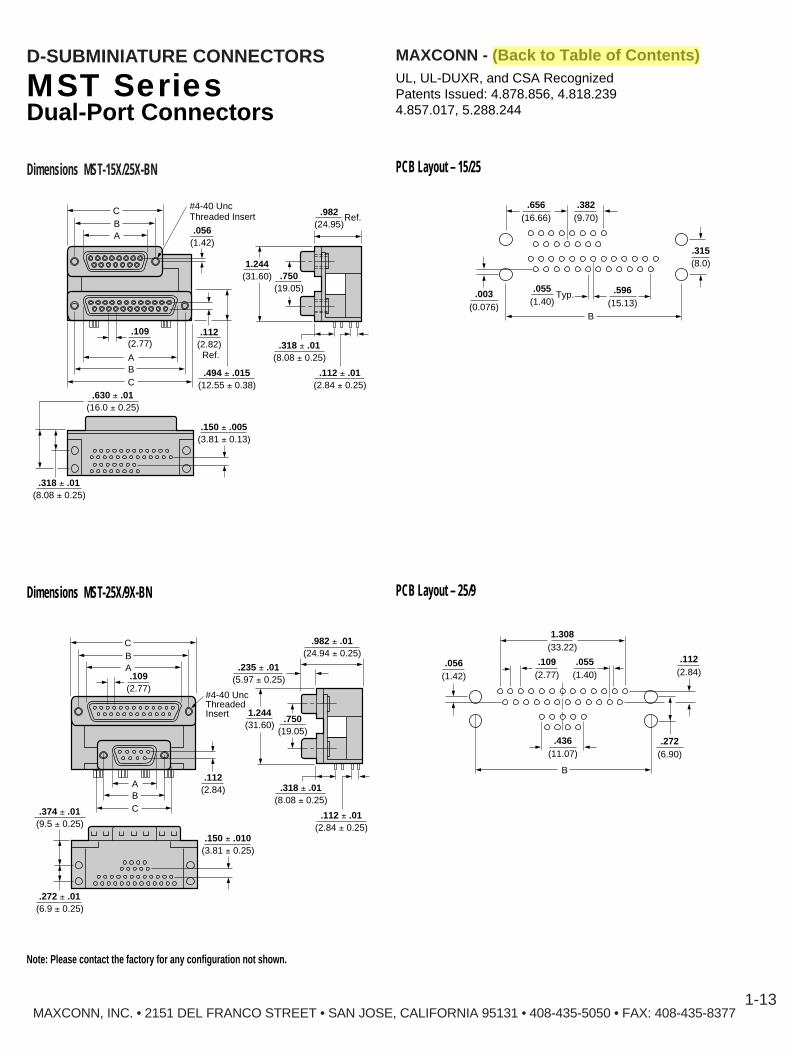
Dimensions MST-15X/25X-BN
#4-40 UncThreadedInsert
.272 ± .01(6.9 ± 0.25)
.150 ± .010(3.81 ± 0.25)
.374 ± .01(9.5 ± 0.25)
.318 ± .01(8.08 ± 0.25)
.112 ± .01(2.84 ± 0.25)
CB
.982 ± .01(24.94 ± 0.25)
.235 ± .01(5.97 ± 0.25)
.112(2.84)
.109(2.77)
A
ABC
.750(19.05)
1.244(31.60)
#4-40 UncThreaded Insert
.318 ± .01(8.08 ± 0.25)
.150 ± .005(3.81 ± 0.13)
.630 ± .01(16.0 ± 0.25)
.494 ± .015(12.55 ± 0.38)
.318 ± .01(8.08 ± 0.25)
.112 ± .01(2.84 ± 0.25)
.056(1.42)
CBA
ABC
.112(2.82)
.982(24.95)
Ref.
Ref.
.750(19.05)
1.244(31.60)
.109(2.77)
.003(0.076)
.656(16.66)
.382(9.70)
.315(8.0)
.055(1.40)
Typ. .596(15.13)
B
.056(1.42)
.112(2.84)
.055(1.40)
.109(2.77)
1.308(33.22)
.436(11.07)
.272(6.90)
B
Dimensions MST-25X/9X-BN PCB Layout – 25/9
PCB Layout – 15/25
MST SeriesDual-Port Connectors
Note: Please contact the factory for any configuration not shown.
UL, UL-DUXR, and CSA RecognizedPatents Issued: 4.878.856, 4.818.2394.857.017, 5.288.244

f .041 ± .003(f 1.04 ± 0.076)
.112(2.84)
Dia. (34 Holes)
.100(2.54)
.085(2.16)
.275(6.99)
.350(8.89)
.085(2.16)
.100(2.54)
.275(6.99)
.109(2.76)
.055(1.40)
.109(2.76)
.404(10.26)
.055(1.40)
.436(11.08)
Edge of PCB
PCB HOLE LAYOUT 15/13W3
MAXCONN - (Back to Table of Contents)D-SUBMINIATURE CONNECTORS
DIMENSIONS MST-15S/13W3-BN15 POSITION FEMALE (TOP)13W3 COAXIAL (BOTTOM)
1.244(31.60)
1.312(33.32)
.750(19.05)
.112(2.84)
.311(7.80)
.235(5.97)
.100(2.54)
.112(2.84)
.404(10.26)
.784(19.91)
.125(3.18)Ref.
.247(627)
.494(12.55)
.971(24.66)
1.541(39.14)
1.312(33.32)
2.088(53.04)
1.852(47.04)
1.511(38.38)
.100(2.54)
MAXCONN, INC. • 2151 DEL FRANCO STREET • SAN JOSE, CALIFORNIA 95131 • 408-435-5050 • FAX: 408-435-83771-14
MST SeriesDual-Port Connectors
DIMENSIONS MST-25S/9P & HD15S–BN25 POSITION FEMALE (TOP)9 POSITION & HIGH DENSITY 15 POSITION (BOTTOM)
2.401(60.98)
0.104(2.64)
0.709(18.00)
1
6
16
11
55
10
15
13
25
1
14
9 0.522(13.26)
PCB Edge0.350(8.89)
0.100(2.54)
0.100(2.54)
0.146(3.71)
0.056(1.42)
0.318(8.08)
0.696(17.68)
0.125(3.18)Dia.
x20.043(1.09)
x49 Dia.
0.546(13.87)
0.109(2.77)
0.090(2.29)
0.055(1.38)0.109
(2.77)#4-40 Uncx6
0.311(7.90)
1.511 ± 0.010(38.38 ± 0.25)
0.329(8.36)
0.666(16.92)0.984
(24.99)
0.374(9.50)
2.637(66.98)
2.401 ± 0.007(60.98 ± 0.19)
Mating Face
0.643
159
(16.33)0.984
(24.99)
1.244(31.60)
0.126(3.20)
Dia.
0.125(3.18)
7.50(19.06)
0.234(5.95)
MaxconnLogo
0.350(8.89)0.100(2.54)0.100(2.54)
PC BoardLock x2
0.090(2.29)
1.852 ± 0.005(47.04 ± 0.13)
PCB HOLE LAYOUT 25/9 & HD15
UL, UL-DUXR, and CSA RecognizedPatents Issued: 4.878.856, 4.818.2394.857.017, 5.288.244
Note: Please contact the factory for any configuration not shown.

MAXCONN - (Back to Table of Contents)D-SUBMINIATURE CONNECTORS
MAXCONN, INC. • 2151 DEL FRANCO STREET • SAN JOSE, CALIFORNIA 95131 • 408-435-5050 • FAX: 408-435-83771-15
MST SeriesRight Angle Termination
Mounting Options
HOW TO ORDER
PLATING OPTIONS
Option KFour threaded (4-40) mounting holes
.31 ± .015(8.00 ± .38)
.16 ± .015(4.00 ± .38)
Option NFour grounding brackets (locking type)
Option OFour 0.130 diameter non-threaded
Series
Number of Positions (Top)9, 15, 25, 37, HD15
Top Connector GenderP — PlugS — Socket
Number of Positions (Bottom)9, 15, 25, 37, HD15, 13W3
Bottom Connector GenderP — PlugS — Socket
Center to Center Dimension*(D Dimension on Drawing)
A — 0.625B — 0.750 (Most standard)C — 0.900
*Applies to standard configurations. Example: 9 over 9. All othersare B — 0.750 footprint center to center dimenions.
Plating OptionJack Screw (4-40)
Blank — Without jack screwsJ — Four jack screws installed
Mounting OptionsO — Four 0.130 diameter
non-threaded mounting holesK — Four threaded (4-40)
mounting holesN — Four grounding brackets
N2 — Two grounding brackets
MST 25 P / 25 S — A N J 15
Designation Plating Description
Blank Gold flash over 100 microinch (min.) nickel on entire contact area with additional 5 microinch gold (making a totalof 8 microinch gold) on mating end of pin for a length of 0.196 (5.0) min. and 0.118 (3.0) min. on the socket
15 100 microinch (min.) nickel on the entire contact area with 15 microinch gold on mating end of pin for a length of0.196 (5.00mm) min. and 0.118 (3.00mm) min. on the socket. 150 microinch of bright tin-lead is plated on the termination end of the contact
30 100 microinch (min.) nickel on the entire contact area with 30 microinch gold on mating end of pin for a length of0.196 (5.00mm) min. and 0.118 (3.00mm) min. on the socket. 150 microinch of bright tin-lead is plated on the termination end of the contact
Note: Please contact the factory for any configuration not shown.
UL, UL-DUXR, and CSA RecognizedPatents Issued: 4.878.856, 4.818.2394.857.017, 5.288.244

SeriesMSD5MSDH5
Shell SizeE - 9 positions (male)B - 25 positions(female)E - 15 position high-density
PrecisionFormed Contact
Number ofContacts9-Male25-Female15-High-density, female
MAXCONN - (Back to Table of Contents)D-SUBMINIATURE CONNECTORS
MAXCONN, INC. • 2151 DEL FRANCO STREET • SAN JOSE, CALIFORNIA 95131 • 408-435-5050 • FAX: 408-435-83771-16
MSD SeriesSlimline Right-Angle.197 (5mm) Footprints
FEATURES■ Provides two optimum space saving footprints■ UL and CSA recognized E107337 and E145613■ Meets EIA, RS232C and RS449 standards for data communications
input/output connectors■ Bright tin shells for exceptional conductivity and grounding■ Indentations for exceptional grounding and mating retention\■ D-shape connector for polarization
Performance SpecificationsMaterials and FinishShell : Steel material, tin finish and indentations (dimples)Insert : PBT thermoplastic, black color, 30% glass filled, self-extinguishing, 94V-0 ratedContact Material :
Pin – BrassSocket – Phosphor bronze
Contact Finish : Gold flash over nickel on entire contact area with additional 5 microinch gold on mating end of the contact
Riveted Insert : Brass material, nickel finish
Mechanical CharacteristicsContact Retention : Precision formed contact 10 lbsContact Separation Force : 1.0 kg, minimum (total connector)Contact Engagement Force : 12.7 kg, maximum (total connector)
Electrical CharacteristicsContact Current Rating : 3.0 ampsContact Resistance : 20 milliohms maximumDielectric Withstanding Voltage : 500 Vac minimum (250 Vdc)Insulation Resistance : 5000 megohms (5000Vdc) minimumTemperature Rating : -55° C to + 125° C
HOW TO ORDER
MSD5 - E F - 25 S -N -
UL, UL-DUXR, and CSA RecognizedPatents Issued: 4.878.856, 4.818.2394.857.017, 5.288.244
Gold PlatingBlank - 8 microinch
(Standard)1 - 15 microinch2 - 30 microinch
Mounting OptionN - Grounding BracketsNJ - Grounding Brackets
with Jack Screws
Contact TypeP - Male (plug) S - Female (socket)
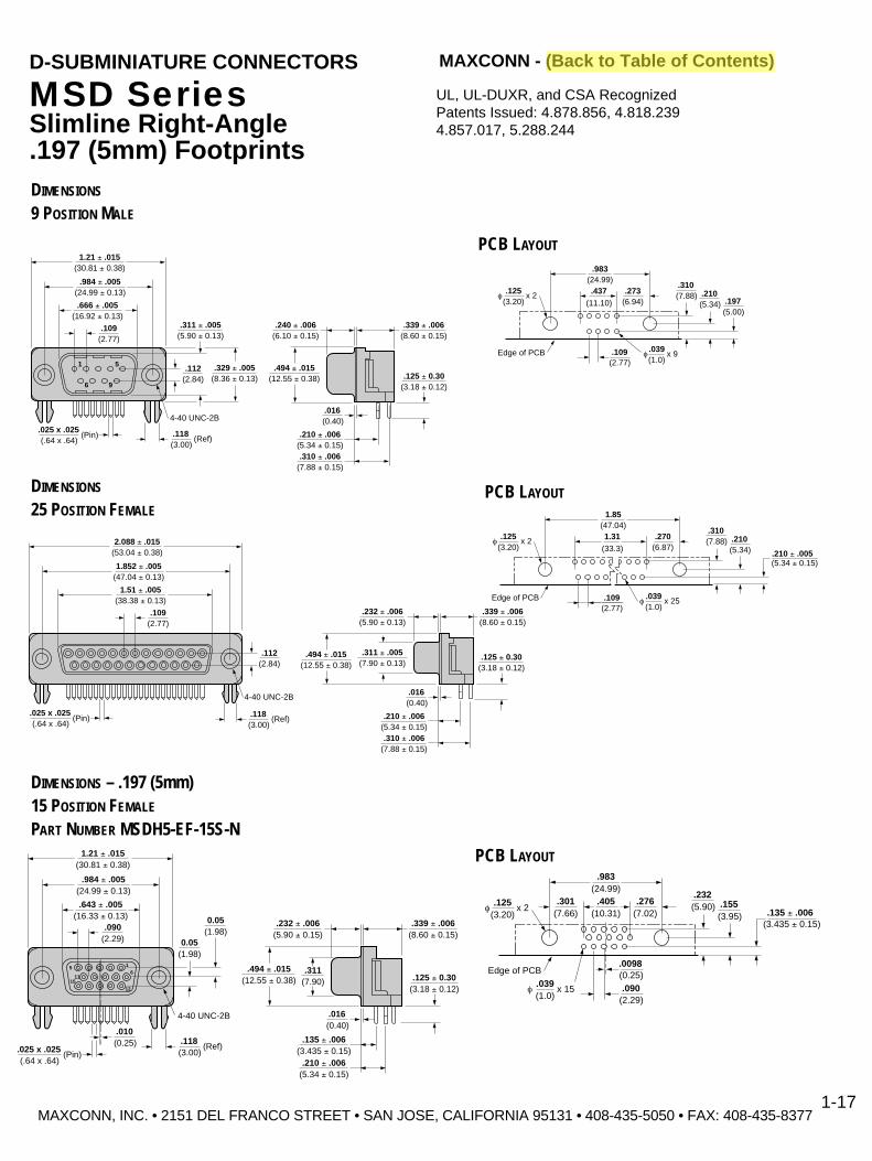
.039(1.0)
x 9f
.437(11.10)
.273(6.94)
.983(24.99)
.109(2.77)
.310(7.88) .210
(5.34) .197(5.00)
Edge of PCB
.125(3.20)
x 2f
PCB LAYOUT
DIMENSIONS
9 POSITION MALE
.984 ± .005(24.99 ± 0.13)
1.21 ± .015(30.81 ± 0.38)
.329 ± .005(8.36 ± 0.13)
.311 ± .005(5.90 ± 0.13)
.240 ± .006(6.10 ± 0.15)
.339 ± .006(8.60 ± 0.15)
.125 ± 0.30(3.18 ± 0.12)
.494 ± .015(12.55 ± 0.38)
.210 ± .006(5.34 ± 0.15)
.109
1
6 9
5
(2.77)
.112(2.84)
4-40 UNC-2B
(Ref).118(3.00)
.016(0.40)
.025 x .025(.64 x .64)
(Pin)
.310 ± .006(7.88 ± 0.15)
.666 ± .005(16.92 ± 0.13)
MAXCONN - (Back to Table of Contents)D-SUBMINIATURE CONNECTORS
MSD SeriesSlimline Right-Angle.197 (5mm) Footprints
1.852 ± .005(47.04 ± 0.13)
2.088 ± .015(53.04 ± 0.38)
.109(2.77)
.112(2.84)
4-40 UNC-2B
(Ref).118(3.00)
.025 x .025(.64 x .64)
(Pin)
1.51 ± .005(38.38 ± 0.13)
.232 ± .006(5.90 ± 0.13)
.339 ± .006(8.60 ± 0.15)
.125 ± 0.30(3.18 ± 0.12)
.494 ± .015(12.55 ± 0.38)
.311 ± .005(7.90 ± 0.13)
.210 ± .006(5.34 ± 0.15)
.016(0.40)
.310 ± .006(7.88 ± 0.15)
PCB LAYOUTDIMENSIONS
25 POSITION FEMALE
.125(3.20)
x 2f
.039(1.0)
x 25f
1.31(33.3)
.270(6.87)
1.85(47.04)
.109(2.77)
.310(7.88) .210
(5.34) .210 ± .005(5.34 ± 0.15)
Edge of PCB
MAXCONN, INC. • 2151 DEL FRANCO STREET • SAN JOSE, CALIFORNIA 95131 • 408-435-5050 • FAX: 408-435-8377
UL, UL-DUXR, and CSA RecognizedPatents Issued: 4.878.856, 4.818.2394.857.017, 5.288.244
1-17
4-40 UNC-2B
.984 ± .005(24.99 ± 0.13)
1.21 ± .015(30.81 ± 0.38)
.090
1511
5 16
12
(2.29)
0.05(1.98)
(Ref)
0.05(1.98)
.118(3.00)
.010(0.25)
.643 ± .005(16.33 ± 0.13)
.025 x .025(.64 x .64)
(Pin)
.232 ± .006(5.90 ± 0.15)
.339 ± .006(8.60 ± 0.15)
.125 ± 0.30(3.18 ± 0.12)
.494 ± .015(12.55 ± 0.38)
.311(7.90)
.135 ± .006(3.435 ± 0.15)
.016(0.40)
.210 ± .006(5.34 ± 0.15)
PCB LAYOUT
.301(7.66)
.125(3.20)
x 2f
.039(1.0)
x 15f
.405(10.31)
.983(24.99)
.276(7.02)
.0098(0.25).090
(2.29)
.232(5.90) .155
(3.95) .135 ± .006(3.435 ± 0.15)
Edge of PCB
DIMENSIONS – .197 (5mm)15 POSITION FEMALE
PART NUMBER MSDH5-EF-15S-N

MSMD – E F – 9 P – N J –
MAXCONN - (Back to Table of Contents)D-SUBMINIATURE CONNECTORS
MSMD SeriesSurface Mount, Right Angle
FEATURES■ Meets EIA, RS232C and RS449 standards for data communications■ Bright tin shell for exceptional conductivity and grounding■ D-shape connector for polarization
Performance SpecificationsMaterials and FinishShell : Steel material, tin finish and indentations (dimples)Insert : Thermoplastic, black color, 30% glass filled, self-extinguishing, 94V-0 ratedContact Material :
Pin – BrassSocket – Phosphor bronze
Contact Finish : Gold flash over nickel on entire contact area with additional 5 microinch gold on mating end of the contact
Riveted Insert : Brass material, nickel finish
Mechanical CharacteristicsContact Retention: Precision formed contact 10 lbsContact Separation Force : 1.0 kg, minimum (total connector)Contact Engagement Force : 12.7 kg, maximum (total connector)
Electrical CharacteristicsContact Current Rating : 3.0 ampsContact Resistance : 20 milliohms maximumDielectric Withstanding Voltage : 500 Vac minimum (250 Vdc)Insulation Resistance : 5000 megohms (5000Vdc) minimumTemperature Rating : -55° C to + 125° CDIMENSIONS
UL, UL-DUXR, and CSA RecognizedPatents Issued: 4.878.856, 4.818.2394.857.017, 5.288.244
PCB LAYOUT
HOW TO ORDER
Series
Shell SizeE – 9 (male)A – 15 (female)B – 25 (female)
Precision Formed Contact
Number of Positions9 – Male15 – Female25 – Female
Gold PlatingBlank – 8 microinch15 – 15 microinch30 – 30 microinch
Mounting OptionN – Grounding BracketNJ – Grounding Bracket
with Jack Screws
Contact TypeP – Male (plug)S – Female (socket)
(± .13)"A" ± .005
(± .38)"C" ± .015
(± .25)"B" ± .010
(8.36 ± .13).329 ± .005
(5.97 ± .25).235 ± .010(4.50 ± .25)
2-4 #-40UNC
.177 ± .010
(6.00 ± .25).236 ± .010
(1.80 ± .25).071 ± .010
(2.0 ± .38).079 ± .015
(12.54 ± .38).494 ± .015
(± .13)"D" ± .005
(± .13)"B" ± .005
(1.38).055 (0.70)
.028
(2.10)f .083(1.60)
f .063(2.00).079
(5.00).197
(1.80).071
(1.00).039
(3.50).138
(2.00).079
(3.25).128
(1.60).063
(0.50).020
MAXCONN, INC. • 2151 DEL FRANCO STREET • SAN JOSE, CALIFORNIA 95131 • 408-435-5050 • FAX: 408-435-83771-18
Number ofContact A B C D
Positions9 0.660 0.984 0.213 0.551
16.92 24.99 30.81 14.0015 0.994 1.312 1.541 1.011
25.25 33.32 39.14 25.6925 1.534 1.852 2.008 1.557
38.96 47.04 53.04 39.54

MAXCONN - (Back to Table of Contents)D-SUBMINIATURE CONNECTORS
MSMDH SeriesSurface Mount, HighDensity , Right Angle
FEATURES■ Meets EIA, RS232C and RS449 standards for data communications■ Bright tin shell for exceptional conductivity and grounding■ D-shape connector for polarization
Performance SpecificationsMaterials and FinishShell : Steel material, tin finish and indentations (dimples)Insert : Thermoplastic, black color, 30% glass filled, self-extinguishing, 94V-0 ratedContact Material :
Pin – BrassSocket – Phosphor bronze
Contact Finish : Gold flash over nickel on entire contact area with additional 5 microinch gold on mating end of contact
Riveted Insert : Brass material, nickel finish
Mechanical CharacteristicsContact Retention: Precision formed contact 10 lbsContact Separation Force : 1.0 kg, minimum (total connector)Contact Engagement Force : 12.7 kg, maximum (total connector)
Electrical CharacteristicsContact Current Rating : 3.0 ampsContact Resistance : 20 milliohms maximumDielectric Withstanding Voltage : 500 Vac minimum (250 Vdc)Insulation Resistance : 5000 megohms (5000Vdc) minimumTemperature Rating : -55° C to + 125° CDIMENSIONS
UL, UL-DUXR, and CSA RecognizedPatents Issued: 4.878.856, 4.818.2394.857.017, 5.288.244
PCB LAYOUT
HOW TO ORDER
MSMDH – E F – 15 S – N –
Series
Shell SizeE
Precision Formed Contact
Number of Positions15
Contact TypeS – Female (socket only)
Gold PlatingBlank – 8 microinch15 – 15 microinch30 – 30 microinch
Mounting OptionN – Grounding BracketNJ – Grounding Bracket
with Jack Screws
(± .13)"A" ± .005
(± .38)"C" ± .015
(± .25)
1510
5 16
11
"B" ± .010
(7.9 ± .13).311 ± .005
(6.17 ± .25).243 ± .010(4.50 ± .25)
2-4 #-40UNC
.177 ± .010
(0.15 ± .10).006 ± .004
(3.4 ± .38).134 ± .015
(1.90 ± .25).075 ± .010
(2.0).079
(12.54 ± .381).494 ± .015
("D" ± .13)"D" ± .005
("B" ± .13)"B" ± .005
(0.76).030 (0.46)
.018
(2.10)f .083
(160)f .063
(2.00).079
(4.00).157
(1.80).071
(1.00).039
(3.50).138
(2.00).079
(3.25).128
(1.60).063
(0.13).005
MAXCONN, INC. • 2151 DEL FRANCO STREET • SAN JOSE, CALIFORNIA 95131 • 408-435-5050 • FAX: 408-435-83771-19
Number of A B C DContact
Positions
15 0.643 0.984 1.213 0.63016.33 24.99 30.81 10.00
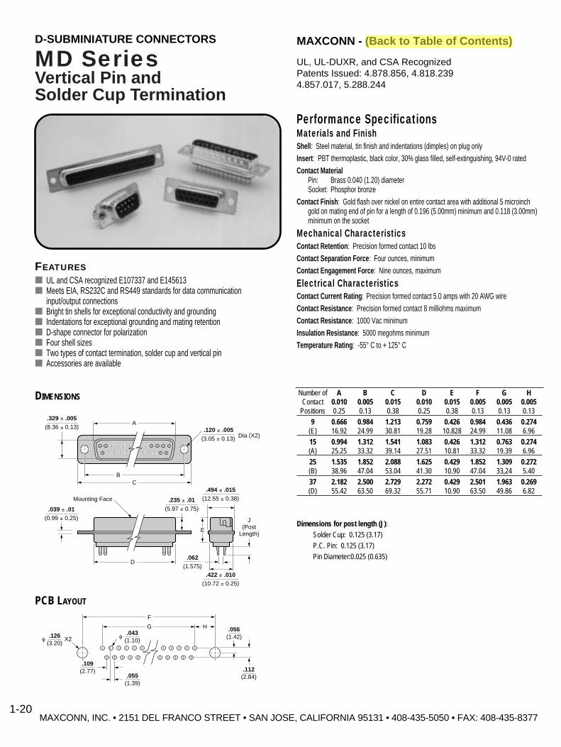
MD SeriesVertical Pin andSolder Cup T ermination
FEATURES■ UL and CSA recognized E107337 and E145613■ Meets EIA, RS232C and RS449 standards for data communication
input/output connections■ Bright tin shells for exceptional conductivity and grounding■ Indentations for exceptional grounding and mating retention■ D-shape connector for polarization■ Four shell sizes■ Two types of contact termination, solder cup and vertical pin■ Accessories are available
Performance SpecificationsMaterials and FinishShell : Steel material, tin finish and indentations (dimples) on plug onlyInsert : PBT thermoplastic, black color, 30% glass filled, self-extinguishing, 94V-0 ratedContact Material
Pin: Brass 0.040 (1.20) diameterSocket: Phosphor bronze
Contact Finish : Gold flash over nickel on entire contact area with additional 5 microinch gold on mating end of pin for a length of 0.196 (5.00mm) minimum and 0.118 (3.00mm) minimum on the socket
Mechanical CharacteristicsContact Retention : Precision formed contact 10 lbsContact Separation Force : Four ounces, minimumContact Engagement Force : Nine ounces, maximum
Electrical CharacteristicsContact Current Rating : Precision formed contact 5.0 amps with 20 AWG wireContact Resistance : Precision formed contact 8 milliohms maximumContact Resistance : 1000 Vac minimumInsulation Resistance : 5000 megohms minimumTemperature Rating : -55° C to + 125° C
Number of A B C D E F G HContact 0.010 0.005 0.015 0.010 0.015 0.005 0.005 0.005
Positions 0.25 0.13 0.38 0.25 0.38 0.13 0.13 0.13
9 0.666 0.984 1.213 0.759 0.426 0.984 0.436 0.274(E) 16.92 24.99 30.81 19.28 10.828 24.99 11.08 6.96
15 0.994 1.312 1.541 1.083 0.426 1.312 0.763 0.274(A) 25.25 33.32 39.14 27.51 10.81 33.32 19.39 6.96
25 1.535 1.852 2.088 1.625 0.429 1.852 1.309 0.272(B) 38.96 47.04 53.04 41.30 10.90 47.04 33,24 5.40
37 2.182 2.500 2.729 2.272 0.429 2.501 1.963 0.269(D) 55.42 63.50 69.32 55.71 10.90 63.50 49.86 6.82
Dimensions for post length (J):Solder Cup: 0.125 (3.17)
P.C. Pin: 0.125 (3.17)
Pin Diameter:0.025 (0.635)
DIMENSIONS
G
F
H
f.043
(1.10)
.109(2.77)
.055(1.39)
f.126
(3.20)X2
.056(1.42)
.112(2.84)
PCB LAYOUT
.329 ± .005(8.36 ± 0.13)
A
BC
.120 ± .005(3.05 ± 0.13)
.039 ± .01(0.99 ± 0.25)
D
Mounting Face .235 ± .01(5.97 ± 0.75)
.494 ± .015(12.55 ± 0.38)
.422 ± .010(10.72 ± 0.25)
E
J(Post
Length)
.062(1.575)
Dia (X2)
MAXCONN, INC. • 2151 DEL FRANCO STREET • SAN JOSE, CALIFORNIA 95131 • 408-435-5050 • FAX: 408-435-8377
MAXCONN - (Back to Table of Contents)D-SUBMINIATURE CONNECTORS
1-20
UL, UL-DUXR, and CSA RecognizedPatents Issued: 4.878.856, 4.818.2394.857.017, 5.288.244

MD SeriesVertical Pin and Solder Cup Termination
Mounting Options
Option KWith #4-40 threaded riveted bushing
Bushing
0.157 ± 0.2(4.0 ± 0.008)
Option KJWith #4-40 threaded riveted bushing andjack screws assembled to connector
Option BR1, BR2With #4-40 threaded riveted bushing, andPCB brackets
Option BRJ1, BRJ2With #4-40 threaded riveted bushing, PCBbrackets and jack screws assembled toconnector
MAXCONN, INC. • 2151 DEL FRANCO STREET • SAN JOSE, CALIFORNIA 95131 • 408-435-5050 • FAX: 408-435-8377
D
D
MAXCONN - (Back to Table of Contents)D-SUBMINIATURE CONNECTORS
1-21
Option K
Option KJ
Option BR
Option BRJ
Dimensions
BR1 0.236 (6.00mm)
BR2 With ferrite
Dimensions
BRJ1 0.236 (6.00mm)
BRJ2 With ferrite
HOW TO ORDER
MD – E C – 25 P – K
Series
Shell SizeShell NumberSize of ContactsE 9A 15B 25C 37
Mounting Option(As shown above)
Contact TypeP – Male (plug)S – Female (socket)
PrecisionFormedContactA – Solder cupC – Vertical pin
No. ofPositions9, 15, 25, 37
Option KS, KSJ, and KSJXStandard fixed hex and fixed roundedstandoff sizes 3.0(0.118), 4.0(0.157),5.7(0.225), 6.0(0.236), 6.35(0.25),6.5(0.256)
.118(3.00)
Option KS.118(3.00)
Option KSJ
5.7(.225)
Option KSJX
4-40 Fixed round standoff (Standard) 4-40 Fixed hex nut (Standard) 4-40 Fixed hex nut (Standard)
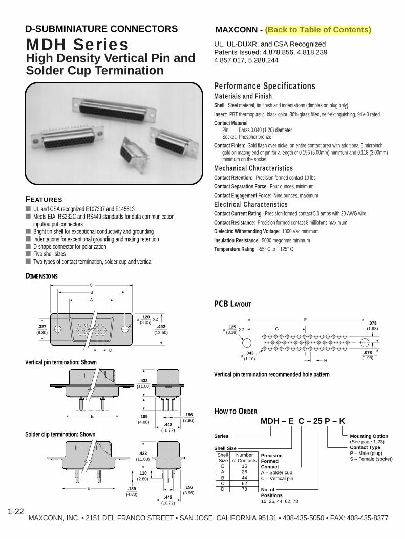
Performance SpecificationsMaterials and FinishShell : Steel material, tin finish and indentations (dimples on plug only)Insert : PBT thermoplastic, black color, 30% glass filled, self-extinguishing, 94V-0 ratedContact Material
Pin: Brass 0.040 (1.20) diameterSocket: Phosphor bronze
Contact Finish : Gold flash over nickel on entire contact area with additional 5 microinch gold on mating end of pin for a length of 0.196 (5.00mm) minimum and 0.118 (3.00mm) minimum on the socket
Mechanical CharacteristicsContact Retention : Precision formed contact 10 lbsContact Separation Force : Four ounces, minimumContact Engagement Force : Nine ounces, maximum
Electrical CharacteristicsContact Current Rating : Precision formed contact 5.0 amps with 20 AWG wireContact Resistance : Precision formed contact 8 milliohms maximumDielectric Withstanding Voltage : 1000 Vac minimumInsulation Resistance : 5000 megohms minimumTemperature Rating : -55° C to + 125° C
MAXCONN, INC. • 2151 DEL FRANCO STREET • SAN JOSE, CALIFORNIA 95131 • 408-435-5050 • FAX: 408-435-8377
MDH SeriesHigh Density V ertical Pin andSolder Cup T ermination
FEATURES■ UL and CSA recognized E107337 and E145613■ Meets EIA, RS232C and RS449 standards for data communication
input/output connectors■ Bright tin shell for exceptional conductivity and grounding■ Indentations for exceptional grounding and mating retention■ D-shape connector for polarization■ Five shell sizes■ Two types of contact termination, solder cup and vertical
DIMENSIONS
.078(1.98)f
.125(3.18)
X2
f.043
(1.10)
.078(1.98)
G
F
H
PCB LAYOUT
E
E
.156(3.96)
.442(10.72)
.189(4.80)
.433(11.00)
.156(3.96)
.442(10.72)
.189(4.80)
.433(11.00)
.110(2.80)
.327(8.30)
C
D
B
A
f.120
(3.05)X2
.492(12.50)
MAXCONN - (Back to Table of Contents)D-SUBMINIATURE CONNECTORS
Vertical pin termination recommended hole pattern
Vertical pin termination: Shown
Solder clip termination: Shown
1-22
UL, UL-DUXR, and CSA RecognizedPatents Issued: 4.878.856, 4.818.2394.857.017, 5.288.244
HOW TO ORDER
MDH – E C – 25 P – K
Series
Shell SizeShell NumberSize of ContactsE 15A 26B 44C 62D 78
Mounting Option(See page 1-23)Contact TypeP – Male (plug)S – Female (socket)
PrecisionFormedContactA – Solder cupC – Vertical pin
No. ofPositions15, 26, 44, 62, 78

Number of A B C D E F G HContact
Positions
15 Male 0.665 0.984 1.213 0.090 0.760 0.984 0.492 0.090(E) 16.90 24.99 30.80 2.29 19.30 24.99 12.50 2.29
15 Female 0.642 0.984 1.213 0.090 0.760 0.984 0.492 0.090(E) 16.30 24.99 30.80 2.29 10.30 24.99 12.50 2.29
26 Male 0.996 1.312 1.539 0.090 1.083 1.312 0.656 0.090(A) 25.30 33.32 39.10 2.29 27.50 33.32 16.66 2,29
26 Female 0.972 1.312 1.539 0.090 1.083 1.312 0.656 0.090(A) 24.79 33.32 39.10 2.29 27.50 33.32 16.66 2.29
44 Male 1.535 1.852 2.087 0.090 1.626 1.852 0.926 0.090(B) 39.00 47.04 53.00 2.29 41.30 47.04 23.52 2.29
44 Female 1.512 1.852 2.0870 0.090 1.626 1.852 0.926 0.090(B) 38.40 47.04 53.00 2.29 41.30 47.04 23.52 2.29
62 Male 2.181 2.500 2.728 0.095 2.272 2.500 1.250 0.095(C) 55.40 63.50 69.30 2.41 57.70 63.50 31.75 2.41
62 Female 2.157 2.500 2.728 0.095 2.272 2.500 1.250 0.095(C) 54.80 63.500 69.30 2.41 57.70 63.50 31.75 2.41
78 Male 2.406 2.406 2.638 0.089 2.178 2.406 1.203 0.089(D) 61.12 61.12 67.00 2.41 55.32 61.12 30.56 2.41
78 Female 2.406 2.406 2.638 0.089 2.178 2.406 1.203 0.089(D) 61.12 61.12 67.00 2.41 55.32 61.12 30.56 2.41
Bushing
0.157 ± 0.2(4.0 ± 0.008)
MDH Series High-Density, Vertical Pin andSolder Cup Termination
Mounting OptionsOption K
With riveted threaded 4-40 bushing
MAXCONN, INC. • 2151 DEL FRANCO STREET • SAN JOSE, CALIFORNIA 95131 • 408-435-5050 • FAX: 408-435-8377
MAXCONN - (Back to Table of Contents)D-SUBMINIATURE CONNECTORS
1-23
Option KJWith #4-40 threaded riveted clinch nuts andjack screws assembled to connector
Option BR1, BR2With #4-40 threaded riveted brackets
Option BRJ1, BRJ2With #4-40 threaded riveted brackets andjack screws assembled to connector
D
D
Option K
Option KJ
Option BR
Option BRJ
Dimensions
BR1 0.236 (6.00mm)
BR2 With ferrite
Dimensions
BRJ1 0.236 (6.00mm)
BRJ2 With ferrite
Option KS (Not Shown)With #4-40 threaded round standoff on PCBside

MC SeriesHousing forCrimp Contacts
Performance SpecificationsMaterials and FinishShell : Steel material, tin finish and indentations (dimples) on plug onlyInsert : PBT thermoplastic, black color, 30% glass filled, self-extinguishing, 94V-0 ratedContact Material
Pin: Brass 0.040 (1.20) diameterSocket: Phosphor bronze
Contact Finish : Type A: Gold flash over 100 microinch nickel on entire contact area with additional
15 microinch gold on mating end of pin for a length of 0.196 (5.00mm) minimum and0.118 (3.00mm) minimum on socket
Type B: Gold flash over 100 microinch nickel on entire contact area with additional 5 microinch gold on mating end of pin for a length of 0.196 (5.00mm) minimum and 0.118 (3.00mm) minimum on socket
Mechanical CharacteristicsContact Retention : Precision formed contact 10 lbsContact Separation Force : Four ounces, minimumContact Engagement Force : Nine ounces, maximumTensile Strength for Crimping Contact : With 24 AWG wire 10 pounds, for 26 AWG wire
7 pounds, and for 28 AWG wire 5 pounds
Electrical CharacteristicsContact Current Rating : Precision formed contact 5.0 amps with 20 AWG wireContact Resistance : Precision formed contact 8 milliohms maximumContact Withstanding Voltage : 1000 Vac minimumInsulation Resistance : 5000 megohms minimumTemperature Rating : -55° C to + 125° C
FEATURES■ UL and CSA recognized E107337 and E145613■ Meets EIA, RS232C and RS449 standards for data communication
input/output connections■ Bright tin shells for exceptional conductivity and grounding■ Indentations for exceptional grounding and mating retention■ D-shape connector for polarization■ Four shell sizes■ Crimp termination
.329 ± .005(8.36 ± 0.13)
A
BC
.120 ± .005
(3.05 ± 0.13)
.039 ± .01(0.99 ± 0.25)
D
Mounting Face.235 ± .01
(5.97 ± 0.75)
.494 ± .015(12.55 ± 0.38)
.422 ± .010(10.72 ± 0.25)
E
.432(10.98)
Max
Dia (X2)
DIMENSIONS
Number of A B C D E Contact 0.010 0.005 0.015 0.010 0.015
Positions 0.25 0.13 0.38 0.25 0.38
9 0.666 0.984 1.213 0.759 0.426(E) 16.923 24.99 30.81 19.28 10.82
15 0.994 1.312 1.541 1.083 0.426(A) 25.256 33.32 39.14 27.51 10.82
25 1.535 1.852 2.088 1.625 0.429(B) 38.96 47.04 53.041 41.30 10.90
37 2.182 2.50 2.729 2.272 0.429(C) 55.428 63.50 69.32 57.71 10.90
HOW TO ORDER
MAXCONN, INC. • 2151 DEL FRANCO STREET • SAN JOSE, CALIFORNIA 95131 • 408-435-5050 • FAX: 408-435-8377
MAXCONN - (Back to Table of Contents)D-SUBMINIATURE CONNECTORS
1-24
MC – B 25 P – K
Series
Shell SizeShell NumberSize of ContactsE 9A 15B 25C 37
Mounting Option(See page 1-13)
Contact TypeP – Male (plug)S – Female (socket)
No. ofPositions9, 15, 25, 37
PIN SPECIFICATIONS
Wire Size Range Ins. Dia. Contact Strip Form Contact Loose Piece Contact No.AWG (mm) (Max.) Finish Pin Socket Pin Socket
0.04 A MP-AT MS-AT MP-AL MS-AL1.02
28-24 0.08-0.20.04 B MP-BT MS-BT MP-BL MS-BL1.02
UL, UL-DUXR, and CSA RecognizedPatents Issued: 4.878.856, 4.818.2394.857.017, 5.288.244

Bushing
0.157 ± 0.2(4.0 ± 0.008)
MC SeriesHousing for Crimp Contacts
Mounting Options
Option K
With 4-40 threaded riveted bushing
MAXCONN, INC. • 2151 DEL FRANCO STREET • SAN JOSE, CALIFORNIA 95131 • 408-435-5050 • FAX: 408-435-8377
MAXCONN - (Back to Table of Contents)D-SUBMINIATURE CONNECTORS
1-25
Pin Socket
PACKAGING SPECIFICATIONSStrip Form: 5,000 contacts per reelLoose Piece : 1,000 per bag
With Insulation Support

MCH SeriesHigh Density Housing forCrimp Contacts
FEATURES■ UL and CSA recognized E107337 and E145613■ Meets EIA, RS232C and RS449 standards for data communication
input/output connections■ Bright tin shells for exceptional conductivity and grounding■ Indentations for exceptional grounding and mating retention■ D-shape connector for polarization■ Five shell sizes■ Crimp termination
Performance SpecificationsMaterials and FinishShell : Steel material, tin finish and indentations (dimples) on plug onlyInsert : PBT thermoplastic, black color, 30% glass filled, self-extinguishing, 94V-0 ratedContact Material
Pin: Brass 0.040 (1.20) diameterSocket: Phosphor bronze
Plating Options :
Type A Gold flash over 100 microinch nickel on entire contact area with additional 15 microinch gold on mating end of pin for a length of 0.196 (5.00mm) minimum and 0.118 (3.00mm) minimum on the socket.
Type B Gold flash over 100 microinch nickel on entire contact area with additional 5 microinch gold on mating end of pin for a length of 0.196 (5.00mm) minimum and 0.118 (3.00mm) minimum on the socket.
Mechanical CharacteristicsContact Retention : Precision formed contact 10 lbsContact Separation Force : Four ounces, minimumContact Engagement Force: Nine ounces, maximum
Electrical CharacteristicsContact Current Rating : 5.0 amps with 20 AWG wireContact Resistance : 8 milliohms maximumContact Resistance : 1000 Vac minimumInsulation Resistance : 5000 megohms minimumTemperature Rating : -55° C to + 125° CDIMENSIONS
E
.492(12.50)
.421(10.70)
.232(5.90)
.433(11.00)
.354(9.00)
ABC
.311(7.90)
10¡D
f.118
(3.00)X2
.156(3.96)
MAXCONN, INC. • 2151 DEL FRANCO STREET • SAN JOSE, CALIFORNIA 95131 • 408-435-5050 • FAX: 408-435-8377
MAXCONN - (Back to Table of Contents)D-SUBMINIATURE CONNECTORS
1-26
UL, UL-DUXR, and CSA RecognizedPatents Issued: 4.878.856, 4.818.2394.857.017, 5.288.244
Number of A B C D EContact
Positions
15 Male 0.666 0.984 1.213 0.090 0.759(E) 16.92 24.99 30.80 2.29 19.28
15 Female 0.643 0.984 1.213 0.090 0.760(E) 16.33 24.99 30.80 2.29 19.30
26 Male 0.994 1.312 1.539 0.090 0.847(A) 25.25 33.32 39.10 2.29 21.51
26 Female 0.971 1.312 1.539 0.090 1.083(A) 24.66 33.32 39.10 2.29 27.50
44 Male 1.510 1.852 2.087 0.090 1.6.26(B) 38.35 47.04 53.00 2.29 41.30
44 Female 1.510 1.852 2.087 0.090 1.6.26(B) 38.35 47.04 53.00 2.29 41.30
62 Male 2.182 2.500 2.728 0.095 2.272(C) 55.42 63.50 69.30 2.41 57.71
62 Female 2.159 2.500 2.728 0.095 2.272(C) 54,84 63.50 69.30 2.41 57.71
78 Male 2.079 2.406 2.638 0.095 2.178(D) 52.81 61.12 67.00 2.41 55.32
78 Female 2.079 2.406 2.638 0.095 2.178(D) 52.43 61.12 67.00 2.41 55.32

Bushing
0.157 ± 0.2(4.0 ± 0.008)
MCH SeriesHigh-Density Housing forCrimp Contacts
Mounting Options
MAXCONN, INC. • 2151 DEL FRANCO STREET • SAN JOSE, CALIFORNIA 95131 • 408-435-5050 • FAX: 408-435-8377
MAXCONN - (Back to Table of Contents)
Option K
With riveted threaded 4-40 bushing
D-SUBMINIATURE CONNECTORS
1-27
MCH – A – 26 – P – K
Series
Shell SizeShell NumberSize of ContactsE 15A 26B 44C 62D 78
Mounting Option(See option K above)
Contact TypeP – PlugS – Socket
No. ofPositions15, 26, 44, 62, 78
Pin Socket
PIN SPECIFICATIONSWire Size Range Ins. Dia. Contact Strip Form Contact Loose Piece Contact No.AWG (mm) (Max.) Finish Pin Socket Pin Socket
0.04 A MPH-AT MSH-AT MPH-AL MSH-AL1.02
28-24 0.08-0.20.04 B MPH-BT MSH-BT MPH-BL MSH-BL1.02
Packaging SpecificationsStrip Form: 5,000 contacts per reelLoose Piece : 1,000 per bag
With Insulation Support
HOW TO ORDER

MAXCONN, INC. • 2151 DEL FRANCO STREET • SAN JOSE, CALIFORNIA 95131 • 408-435-5050 • FAX: 408-435-83771-28
Hoods – Plastic,Metal
MAXCONN - (Back to Table of Contents)D-SUBMINIATURE HARDWARE
FEATURES■ Available in 9, 15, 25 and 37 positions■ Available in blue, ivory, black, medium grey and chrome■ Available in steel, nickel finish■ Supplied with saddle screws and washers
DIMENSIONS – 9 POSITIONS
HOW TO ORDERHDM – 25
Series Shell SizeHDM – ABS (UL 94V-0 rated) plastic, blue color 9, 15, 25, 37HDN – ABS (UL 94V-0 rated) plastic, ivory colorHDO – ABS (UL 94V-0 rated) plastic, black colorHDP – ABS (UL 94V-0 rated) plastic, medium grey colorHDC – ABS (UL 94V-0 rated) plastic, chrome colorHDDC – Steel material, nickel finish
DIMENSIONS – 15 POSITIONS
DIMENSIONS – 25 POSITIONS
DIMENSIONS – 37 POSITIONS
.291 ± .004(7.40 ± 0.1)
f
.496 ± .004(12.60 ± 0.1)
.509 ± .004(12.95 ± 0.1)
.413 ± .004(10.50 ± 0.1)
.649 ± .004(16.50 ± 0.1)
1.54 ± .004(39.30 ± 0.1)
.983 ± .004(24.99 ± 0.1)
1.22 ± .004(31.10 ± 0.1)
.393 ± .004(10.0 ± 0.1)
.295 ± .004(7.50 ± 0.1)
1.85 ± .004(47.04 ± 0.1)
.437 ± .004(11.10 ± 0.1)
f
1.63 ± .004(41.40 ± 0.1)
.287 ± .004(7.30 ± 0.1)
.507 ± .004(12.90 ± 0.1)
.041 ± .004(1.05 ± 0.1)
.641 ± .004(16.30 ± 0.1)
.385 ± .004(9.80 ± 0.1)
.523 ± .004(13.30 ± 0.1)2.10 ± .004
(53.50 ± 0.1)
.547 ± .004(13.90 ± 0.1)
f
2.50 ± .004(63.50 ± 0.1)
.515 ± .004(13.10 ± 0.1)
2.021 ± .004(51.30 ± 0.1)
.791 ± .004(20.10 ± 0.1)
.295 ± .004(7.50 ± 0.1) .047 ± .004
(1.20 ± 0.1)
.50 ± .004(12.70 ± 0.1)
.956 ± .004(24.30 ± 0.1)
.40 ± .004(10.15 ± 0.1)
.661 ± .004(16.80 ± 0.1)
2.75 ± .004(69.80 ± 0.1)
.401(10.20)
f
.527 ± .004(13.40 ± 0.1)
.141 ± .004(3.60 ± 0.1)
.511 ± .004(13.0 ± 0.1)
1.47 ± .004(37.55 ± 0.1)
.708 ± .004(18.0 ± 0.1)
.503 ± .004(12.80 ± 0.1)
.511 ± .004(13.0 ± 0.1)
.370 ± .004(9.40 ± 0.1)
.633 ± .004(16.10 ± 0.1)
1.08 ± .004(27.62 ± 0.1)
.877 ± .004(22.30 ± 0.1)
.716 ± .004(18.20 ± 0.1)
1.09 ± .004(27.70 ± 0.1)
1.31 ± .004(33.32 ± 0.1)
1.53 ± .004(38.95 ± 0.1)

.157(4.00)Metal-Shell or
All Plastic Plugor Receptacle
(Shown forRef. Only)
1.713(43.50)
.425(10.80)
.157(4.00)
4-40 Screw(2 Supplied)
Slide Lock(15 Position)
.039(1.00)
.157(4.00)
.039(1.00) 4-40
0.1C
.106 ± 0.0007(2.70 ± 0.02)
45¡-0.5C
.132 ± 0.0007(3.35 ± 0.02)
.047(1.20)
.049 ± 0.07(1.25 ± 0.02)
.250(6.35)
.346 ± 0.04(8.80 ± 0.10)
Slide Lock Assembly
4-40 SCREW DIMENSIONSDIMENSIONS
Specifications
Slide Lock AssemblyMaterials : Spring steel, 0.024 — 0.026 thick, tempered and heat treated to Rockwell RC44-46 specificationsFinish : Nickel plated
4-40 ScrewMaterial : BrassFinish : None
MAXCONN, INC. • 2151 DEL FRANCO STREET • SAN JOSE, CALIFORNIA 95131 • 408-435-5050 • FAX: 408-435-8377
MAXCONN - (Back to Table of Contents)D-SUBMINIATURE HARDWARE
1-29
PART NUMBER MDA51220-1
Kit(2 Sets per Bag)P/N MD20418-50
BulkP/N JS-40
Kit(2 Sets per Bag)P/N MD20418-2
BulkP/N JS-15
.429(10.9) Flat Washers
(2 Supplied)
Lock Washer
Hex Nut
Flat Washers(2 Supplied)
Lock Washer
Hex Nut
.264(6.7)
.264(6.7)
.375(9.53)
JACK SCREWS
Accessories and Hardware


MJDS Series - Stacked Modular Jacks (27.80 mm) 8 to 12 Ports, Shielded and Non-Shielded 2-2
MJDS-LG5 Series - Stacked Modular Jacks 2 to 16 Ports, Shielded 2-4MJFS Series - Filtered Transformer, Shielded, Standard PCB Footprint 2-6MJH Series - Low Profile (.498 Height) Non-Shielded,
Partially Shielded 2-10MJH-R Series - Single Cavity, Standard Height, Non-Shielded,
Shielded 2-11MJH-V Series - Vertical, Non-Shielded, Shielded 2-13MJH-G Series - Non-Shielded, Shielded 2 to 12 Ports 2-14MJL Series - Ultra-Low Profile, (.453 Height) Non-Shielded 2-16MJL-G Series - Gang Ultra-Low Profile Height, Non-Shielded,
Shielded 2-17MJLS Series - Ultra-Low Profile, (.460 Height) Shielded 2-18MJLSS Series - Ultra-Low Profile (.460 Height) Surface Mount,
Shielded, Non-Shielded 2-20MJH-C Series - RJII /RJ45 Combination, Low Profile, .543 High 2-22MJA Series - Right Angle, PC Mount 2-23MJB Series - Right Angle, PC Mount 2-24MJG Series - 6 or 8 Position, Right Angle, Ganged, Non-Shielded 2-25MJG Series - 6 or 8 Position, Vertical, Ganged, Non-Shielded 2-26MJF Series - Right Angle, PC Mount 2-27MJM Series - Right Angle, PC Mount 2-28MJP Series - Vertical, PC Mount 2-29MCJ-P Series - IDC Panel Jack 2-30MJC-88 Series - Modular Jack Coupler Non-Shielded, Shielded 2-31MP Series - Non-Shielded, Shielded 2-32MP8B Series - Cable Boots with and without Latch Protectors 2-34MP Series - Male Cable Assembly 2-35
MAXCONN, INC. - 2151 DEL FRANCO STREETo SAN JOSE, CALIFORNIA 95131 - 408-435-5050,, FAX: 408-435-8377MAXCONN EUROPE. - Edlingerstr. 3 - D-81543 Munich/München Tel: 49 (0) 89-65 11 30 88, Fax: 49 (0) 89-65 11 30 88
E-Mail: [email protected] - Web: http://www.eucon-elektronik.com
Modular JackConnectors

MAXCONN - (Back to Table of Contents)MODULAR JACK CONNECT ORS
MJDS SeriesStacked Modular Jacks (27.80mm)8 to 12Ports, Shielded & Non-Shielded
MAXCONN, INC. • 2151 DEL FRANCO STREET • SAN JOSE, CALIFORNIA 95131 • 408-435-5050 • FAX: 408-435-83772-2
FEATURES■ Meets FCC requirements■ Non-shielded, shielded■ Snapp peg mounting■ 8 and 12 ports■ UL and CSA approved
DIMENSIONS (12 PORT SHOWN)
1.094(27.80)
1.122(28.50)
B
A
Performance SpecificationsMaterials and FinishHousing : Glass filled polyester, Zytel FR50,UL 94V-0 rated, blackContacts : 0.35mm phosphor bronze, gold plated, with tin leads, over nickelShielding : 0.25mm thickness copper alloy plated with 90 microinch tin
Mechanical CharacteristicsDurability : 1000 mating cycles
Electrical CharacteristicsCurrent/Voltage : 150Vac at 1.5 amps maximum at 25°CDielectric Withstanding Voltage : 1000 Vac RMS minimum, 60 HzInsulation Resistance : 500 megohms minimumContact Resistance : 30 milliohms maximumOperating Temperature : -40° C to + 125° C
No. of Ports A Band Style
8* 2.33 2.1059.12 53.34
12* 3.43 3.2087.12 81.28
NOTE: Consult factory for recommended PCB layout.
* Also available in 25.3mm height(MJDS-LG5-Series)

MAXCONN - (Back to Table of Contents)MODULAR JACK CONNECT ORS
MAXCONN, INC. • 2151 DEL FRANCO STREET • SAN JOSE, CALIFORNIA 95131 • 408-435-5050 • FAX: 408-435-83772-3
MJDS SeriesStacked Modular Jacks8 to 12 Ports, Shielded and Non-shielded
Grounding Tab Combinations (12 Ports Shown)
HOW TO ORDER
MJDS - G - 8 8 - 2 - PG4 T - 30
SeriesS – Shielded
GangedG – Standard 27.8mm height
Number of Positions8
Number of Contacts8
Number of Ports8, 12
Contact PlatingBlank — 10 microinch gold
30 — 30 microinch gold (Std)50 — 50 microinch gold
PCB Grounding OptionsBlank — Standard one backside,
three per sideT — Grounding pins between
each port. (backside)S — Between each port
(middle row/backside)X — No rear ground pin
Panel Grounding OptionBlank – Without grounding tabs PG4 – Grounding flange (sides)
Grounding tabs (top/bottom)
Shown with Panel Ground Option (PG4 Option)
0.065 (1.65) x 20 0.115 (2.92)
15¡ x 20

MAXCONN - (Back to Table of Contents)MODULAR JACK CONNECT ORS
MJDS-LG5 SeriesStacked Modular Jacks2 to 16 Ports, Shielded
MAXCONN, INC. • 2151 DEL FRANCO STREET • SAN JOSE, CALIFORNIA 95131 • 408-435-5050 • FAX: 408-435-83772-4
FEATURES■ Low profile■ Meets FCC requirements■ Non-shielded, shielded■ Category 5E compliant■ Enhanced panel and ground shield options■ UL and CSA approved E107337 and E145613
DIMENSIONS
Performance SpecificationsMaterials and FinishHousing : Glass filled polyester, Zytel FR50, UL 94V-0 rated, blackContacts : 0.35mm phosphor bronze, gold plated with tin leads over nickelShielding : 0.25mm thickness copper alloy plated with 90 microinch tin
Mechanical CharacteristicsDurability : 1000 mating cycles
Electrical CharacteristicsCurrent/Voltage : 150 Vac at 1.5 amps maximum at 25°CDielectric Withstanding Voltage : 1000 Vac RMS minimum, 60 HzInsulation Resistance : 500 megohms minimumContact Resistance : 30 milliohms maximumOperating Temperature : -40° C to + 125° C
Description No. of Ports A Band Style
2 x 1 Ports 2 0.680 0.45017.27 11.43
2 x 2 Ports 4 1.230 1.00031.24 25.40
2 x 3 Ports 6 1.780 1.55045.21 39.37
2 x 4 Ports 8 2.330 2.10059.18 53.34
2 x 6 Ports 12 3.430 3.20087.12 81.28
2 x 8 Ports 16 4.530 4.300115.06 109.22
NOTE: Consult factory for recommended PCB layout.
Max
A
B
0.165 ± 0.010(4.19 ± 0.25)
0.143 ± 0.010(3.62 ± 0.25)
0.353(8.96)
0.425(10.80)
0.995(25.27)
1.120(28.44)

MAXCONN - (Back to Table of Contents)MODULAR JACK CONNECT ORS
0.039(1.00)
0.118(3.00)Max
Detail AGF Type Tab
0.030(0.076)
0.040(1.02)
Detail ATF Type Tab
MAXCONN, INC. • 2151 DEL FRANCO STREET • SAN JOSE, CALIFORNIA 95131 • 408-435-5050 • FAX: 408-435-83772-5
MJDS SeriesStacked Modular Jacks,2 to 16 Port
HOW TO ORDER
MJDS - LG5-8 8 -X XXX X - 30
SeriesS – Shielded
GangedLG5 – Low profile (25.27)
Number of Positions6, 8
Number of Contacts6 – 6 Contacts8 – 8 Contacts
Number of Ports2, 4, 6, 8, 12, 16
Contact PlatingBlank — 10 microinch gold
30 — 30 microinch gold (standard)50 — 50 microinch gold.
PCBGrounding OptionBlank — Standard one backside,
three per side T — Grounding pins between every
port (rear)(backside) Available only on 4, 6, 8 and 12 ports
P — Grounding pins between every other port
S — Grounding pins between each port(backside) and in the center of front and rear contact rows
X — No rear ground pins
Panel Grounding OptionsBlank — Without grounding tabsTF5 — Forward grounding flang (sides)GF5 — Rearward grounding flang (1 piece)GF8 — Rearward grounding flang and
forward bottomGF9 — Rearward grounding flang and
rearward bottom

MAXCONN - (Back to Table of Contents)MODULAR JACK CONNECT ORS
MJFS SeriesFiltered T ransformer , Shielded,Standard PCB Footprint
MAXCONN, INC. • 2151 DEL FRANCO STREET • SAN JOSE, CALIFORNIA 95131 • 408-435-5050 • FAX: 408-435-83772-6
Performance SpecificationsMaterials and FinishHousing : Glass filled polyester, UL 94V-0 rated, high-temp.,blackContacts : 0.35mm Phosphor bronze (C5210)Contact Plating : Palladium nickel 50 microinchShielding : 0.25mm thickness copper alloy plated with 90 microinch tin
Mechanical CharacteristicsDurability : 1000 mating cycles
Electrical CharacteristicsCurrent/Voltage : 150Vac at 1.5 amps maximum at 25°CDielectric Withstanding Voltage : 1000 Vac RMS minimum, 60 HzContact Resistance : 30 milliohms maximumInsulation Resistance : 500 megohms minimumOperating Temperature : –40°C to +125°C
DIMENSIONS
0.625(15.88)
.125 MaxPatented
(317)
(3.05)
1.20
.550(13.97)
(27.94)
.120
R1-FrontGround
Pin
Max
Rear Ground Pin
PCB LAYOUT TOP VIEW
0.250(6.35)
0.035(0.89)
±.003f
0.062(1.57)
f
0.125(3.18) (3.25 Max)
2x ±.003
2x ±.003
2x
f
0.305(7.75)0.08
(2.032)
0.200(5.08)
0.450(11.43)
0.610(15.49)
0.050(1.27) 0.025
(0.64)0.100(2.54)
0.100(2.54)
0.120(3.05)
FEATURES■ UL and CSA approved E107337 and E145613■ Meets FCC requirements■ Meets IEEE 802.3 requirements 10/100BaseT, and 100BaseT■ Space saving■ Optimized performance■ Standard PCB layout■ Drop in replacement for existing connector
HOW TO ORDER
MJFS - R - 8 8 - - GF5 - XXF1
Series
MountingR – Right angleR1 – Right angle
Front ground pinG – Gand type
Number of Positions6, 8
Number of Contacts6, 8
Number of Ports2, 4, 6, 8Blank – Single port
Grounding TabsBlank No grounding tabsGF5 Ground Flange
Notes: *Consult factory for panel cutout, and further specifications. Custom designswelcomed. ** Request from factory a detailed filter diagram for each specific application. Alsoprovide factory with the specific semiconductor needing the filtering and Maxconn canprovide a specification which will match the recommendation given by thesemiconductor manufacturer.
FilterXXF1 — ISDNXXF2 — 10BaseTXXF3 — 100BaseTXXF4 — Tokin RIng
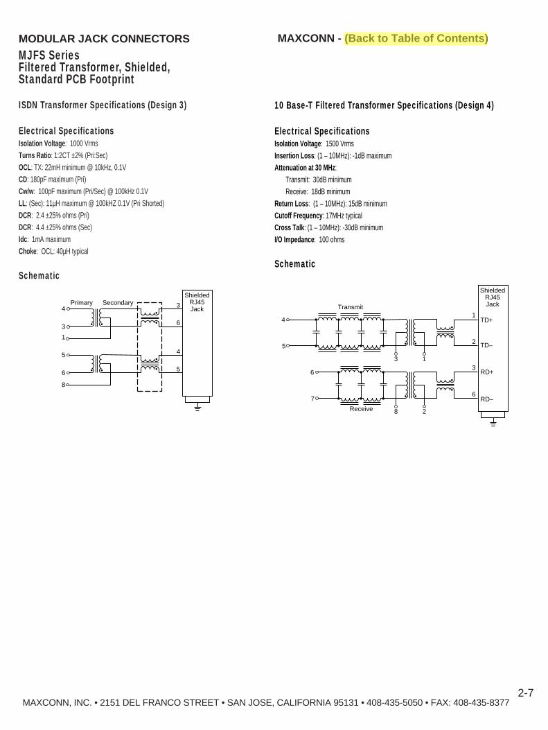
MAXCONN, INC. • 2151 DEL FRANCO STREET • SAN JOSE, CALIFORNIA 95131 • 408-435-5050 • FAX: 408-435-83772-7
MAXCONN - (Back to Table of Contents)
MJFS SeriesFiltered Transformer, Shielded,Standard PCB Footprint
MODULAR JACK CONNECT ORS
ISDN Transformer Specifications (Design 3)
Electrical SpecificationsIsolation Voltage : 1000 VrmsTurns Ratio : 1:2CT ±2% (Pri:Sec)OCL: TX: 22mH minimum @ 10kHz, 0.1VCD: 180pF maximum (Pri)Cw/w : 100pF maximum (Pri/Sec) @ 100kHz 0.1VLL : (Sec): 11µH maximum @ 100kHZ 0.1V (Pri Shorted)DCR: 2.4 ±25% ohms (Pri)DCR: 4.4 ±25% ohms (Sec)Idc : 1mA maximumChoke : OCL: 40µH typical
Schematic
Primary Secondary4
3
1
3
6
4
5
ShieldedRJ45Jack
5
6
8
Transmit
Receive
3 1
1
2
ShieldedRJ45Jack
TD+
TD–
RD+
RD–
5
4
8 2
3
67
6
10 Base-T Filtered Transformer Specifications (Design 4)
Electrical SpecificationsIsolation Voltage : 1500 VrmsInsertion Loss : (1 – 10MHz): -1dB maximumAttenuation at 30 MHz :
Transmit: 30dB minimumReceive: 18dB minimum
Return Loss : (1 – 10MHz): 15dB minimumCutoff Frequency : 17MHz typicalCross Talk : (1 – 10MHz): -30dB minimumI/O Impedance : 100 ohms
Schematic

MAXCONN - (Back to Table of Contents)
MJFS SeriesFiltered Transformer, Shielded,Standard PCB Footprint
MODULAR JACK CONNECT ORS
100 Base Combo Filtered Transformer Specifications (Design 6)
Electrical SpecificationsIsolation Voltage : 1500 Vrms (Input to Output)Turns Ratio : TX: 2:1 (±2%), RX: 1:1:1 (±2%)OCL: TX: 140µH minimum, RX: 350 µH minimum @ 100kHz, 100mVRise Time : (10 – 90%): 3.0ns typicalInsertion Loss : (1M – 125 MHz): –1.0dB maximumReturn Loss :
100 kHz – 60 MHz -15 dB minimum (Tx)/ -17 dB minimum Rx60MHz – 100MHz -11dB minimum Tx)/ -15dB minimum Rx)
Common Mode to Differential Mode Attenuation: :100 kHz – 60 MHz -45 dB minimum (Tx)/ -40 dB minimum Rx60MHz – 100MHz -40dB minimum Tx)/ -35dB minimum Rx)
Schematic
8
7
1:1:1 CT
2 CT: 1 CT4
2
3
XF6692Combo
R3, R4, R5, R6, R7, R8: 50 OhmsR1, R2: 75 Ohms
6
5
R1 R2 R8
10nF1KV
R7
Shield
RJ45
8
7
6
5
4
3
2
1
1
R6 R5 R4 R3
ATM 100 Base Filtered Transformer Specifications(Design7)
Electrical SpecificationsIsolation Voltage : 1500 Vrms Rise Time : 2ns typical @ 10 – 90%Insertion Loss : (0.1 – 125 MHz): –1.1dB maximumReturn Loss :
0.1 – 60 MHz -15 dB (Tx)/ -17 dB Rx typical 60 – 125MHz -11dB Tx)/ -15dB (Rx) typical
Cross Talk :0.1 – 60 MHz -40 dB minimum60 – 125MHz -38 dB minimum
Common Mode to Differential Mode Rejection :100 kHz – 60 MHz -45 dB minimum (Tx)/ -40 dB minimum Rx60MHz – 100MHz -40dB minimum Tx)/ -35dB minimum (Rx)
Schematic
MAXCONN, INC. • 2151 DEL FRANCO STREET • SAN JOSE, CALIFORNIA 95131 • 408-435-5050 • FAX: 408-435-83772-8
8
6
RD–
RD+
7 CT
4
2
RX–
RX+
3
CT
TD–
TD+
CT
TX–
TX+
R1 R2 R8
10nF1KV
R7 Shield
RJ45
8
7
6
5
4
3
2
1
1
CMT

MAXCONN, INC. • 2151 DEL FRANCO STREET • SAN JOSE, CALIFORNIA 95131 • 408-435-5050 • FAX: 408-435-83772-9
ATM 100 Base Filtered Transformer Specifications(Design 8)
Electrical SpecificationsIsolation Voltage : 1500 VrmsRise Time : 2.5ns typical @ 10 – 90%Insertion Loss : (0.1 – 125MHz) -1.1dB maximumReturn Loss : (0.1 – 60MHz) -15dB Tx/-17dB Rx typical
(60 – 125MHz) -11dB Tx/-15dB Rx typicalCross Talk : (0.1 –60MHz) -40dB minimum
(60 – 125MHz) -38dB minimumCommon Mode to Differential Mode Rejection :
(0.1 – 60MHz) -45dB Tx/-40dB Rx minimum(60 – 125MHz) -40dB Tx/-35dB Rx minimum
Schematic
8
7
RD–
RD+
6 CT
4
3
RX–
RX+
2
CT
TD–
TD+
CT
TX–
TX+
R1 R2 R8
10nF1KV
R7
Shield
RJ45
8
7
6
5
4
3
2
1
1
CMT
R6 R5 R4 R3
10/100 Base TX Filtered Transformer Specifications(Design 5)
Electrical SpecificationsIsolation Voltage : 2000 VrmsTurns Ratio : 1:1CTPri/Sec DCR : 0.90 ohms maximumRise Time/Fall Time : 4ns tmaximumCw/w (Pri/Sec) : 15pF maximumLeakage Inductance : (Pri): 0.4µH maximumInsertion Loss : (0.1 – 125MHz) -1.1dB maximumReturn Loss : (0.1 – 60MHz) -18dB minimum
(60 – 125MHz) -12dB minimumCross Talk : (0.1 – 125MHz) -38dB minimum
Schematic
8Transmit
Receive4
3
XFATM6Combo
7
R1 R2 R8
10nF2KV
R7
Shield
RJ45
8
7
6
5
4
3
2
1
1
R6 R5 R4 R3
MAXCONN - (Back to Table of Contents)
MJFS SeriesFiltered Transformer, Shielded,Standard PCB Footprint
MODULAR JACK CONNECT ORS

MAXCONN, INC. • 2151 DEL FRANCO STREET • SAN JOSE, CALIFORNIA 95131 • 408-435-5050 • FAX: 408-435-83772-10
MODULAR JACK CONNECT ORS
MJH SeriesLow Profile (.498 Height)Non-Shielded, Partially Shielded
MAXCONN - (Back to Table of Contents)
FEATURES■ Low profile (.498 Height)■ Meets FCC requirements■ UL and CSA approved E107337 and E145613■ 6 and 8 positions■ Non-shielded and partially shielded
Performance SpecificationsMaterials and FinishHousing : Glass filled polyester, UL 94V-0 rated, blackShielding : 0.35mm thickness copper alloy plated with 90 microinch tinContacts : 0.35mm Phosphor bronze, gold plated with 90 microinch tin over nickel
Mechanical CharacteristicsDurability : 1000 mating cycles
Electrical CharacteristicsCurrent/Voltage : 150 Vac at 1.5 amps maximum, at 25°CDielectric Withstanding Voltage : 1000 Vac RMS minimum, 60 HzInsulation Resistance : 500 megohms minimumContact Resistance : 30 milliohms maximumOperating Temperature : -55°C to +125°C
DIMENSIONS
MJH Non-Shielded6 Positions — Shown with panel stops
.400(10.16)
.020(0.51) 0.498 ± .005
(12.65 ± 0.127)
PanelStop
0.150 ± .020(3.81 ± 0.51)
0.350 ± .010(8.89 ± 0.25)
.310 ± .007(7.87 ± 0.18)
.520(13.21)
.138(3.50)
.100(2.54)
.620(15.75)(2.36)
2 Pls
.710(18.03)
.050(1.27)
.0930
.450(11.43)
.020(0.51) 0.498 ± .005
(12.65 ± 0.127)
PanelStop
0.150 ± .020(3.81 ± 0.51)
0.350 ± .010(8.89 ± 0.25)
.310 ± .007(7.87 ± 0.18)
.600(15.24)
.138(3.50)
.100(2.54)
.700(17.78)
Unkeyed
(2.36)2 Pls
.710(18.03)
Keyed
.0930
DIMENSIONS
MJH Non-Shielded8 Positions — Shown with panel stops
DIMENSIONS
MJHS- Shielded8 Positions — Shown with PC ground and shield
.450(11.43)
.105(2.67)
0.538 ± .005(13.66 ± 0.127)
Shield
Typ
WithMetalShield
0.150 ± .020(3.81 ± 0.51)
0.350 ± .010(8.89 ± 0.25)
0.320 ± .010(8.12 ± 0.25)
.625(15.88)
.700(17.78)
.138(3.50)
.100(2.54)
.180(4.57)
.120(3.05)
(1.27)Typ
.720(18.29).050
HOW TO ORDER
MJHS - 8 8 - P - 30
SeriesBlank = Unshielded*S = Shielded
Number of Positions6, 8*
Number of Contacts2, 4, 6, 8, 10**10 available 8P only
StopsBlank — No stopsP — With panel stops (standard for
sheilded version)
PlatingBlank — 10 microinch
gold (Std)30 — 30 microinch
gold50 — 30 microinch
gold
*NOTE: Pin 1 is located to the extreme left of the latch looking inside of the cavity.Consult factory for recommended panel cutouts and PCB layout.

MAXCONN - (Back to Table of Contents)
MAXCONN, INC. • 2151 DEL FRANCO STREET • SAN JOSE, CALIFORNIA 95131 • 408-435-5050 • FAX: 408-435-8377
MODULAR JACK CONNECT ORS
MJH-R SeriesSingle Cavity , Standard Height, Non-Shielded, Shielded
DIMENSIONS
C
BA
0.100(2.54)
0.250(6.35)
0.125
Max
(3.18)
Shown with panelstop (Optional)
2-11
FEATURES■ UL, UL-DUXR and UL-CSA approved E107337 and E145613■ Meets FCC requirements■ Low profile standard height■ Shielded and non-shielded
Performance SpecificationsMaterials and FinishHousing : Glass filled poyester, Zytel FR50, UL 94V-0 rated, blackContacts : 0.45mm Phosphor bronze, gold plated (round wire)orContacts : 0.35mm Phosphor bronze, gold platted (flat wire)Shielding : 0.25mm thickness copper alloy plated with 90 microinch tin over nickel
Mechanical CharacteristicsDurability : 1000 mating cycles
Electrical CharacteristicsContact Current Rating : 125 V at 1.5 amps maximumContact Resistance : 30 milliohms maximumDielectric Withstanding Voltage : 1000 V RMS minimum, 60 HzInsulation Resistance : 500 megohms minimumOperating Temperture : –40°C to +125°C
No. of No. of Dimensions for Shielded VersionPositions Contacts A B C D E
4 4 0.468 0.850 0.537 0.150 0.25011.88 21.60 13.63 3.81 6.35
6 6 0.545 0.850 0.537 0.250 0.35013.84 21.60 13.63 6.35 8.89
8 8 0.625 0.850 0.537 0.350 0.45015.88 21.60 13.63 8.89 11.43
Dimensions for non-shielded Version4 4 0.443 0.810 0.500 — —
11.26 20.54 12.706 6 0.520 0.810 0.500 — —
13.21 20.54 12.708 8 0.600 0.810 0.500 — —
15.24 20.54 12/70
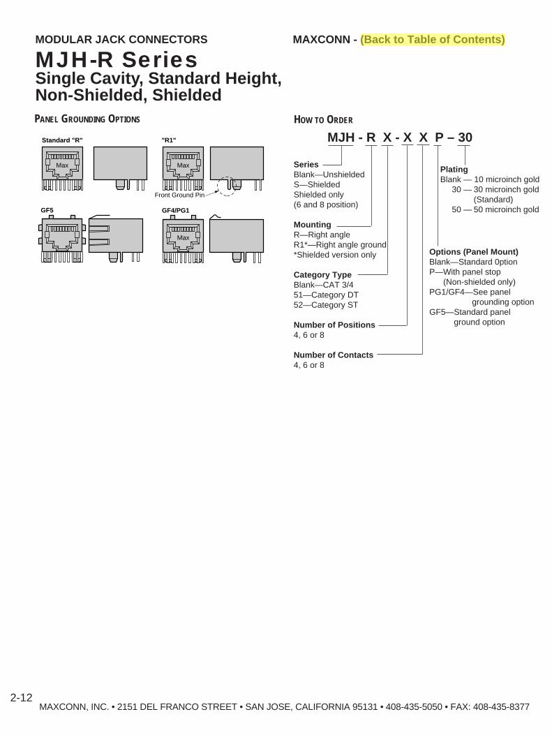
HOW TO ORDER
MJH - R X - X X P – 30
SeriesBlank—UnshieldedS—ShieldedShielded only(6 and 8 position)
MountingR—Right angleR1*—Right angle ground*Shielded version only
Category TypeBlank—CAT 3/451—Category DT52—Category ST
Number of Positions4, 6 or 8
Number of Contacts4, 6 or 8
PlatingBlank — 10 microinch gold
30 — 30 microinch gold(Standard)
50 — 50 microinch gold
Options (Panel Mount)Blank—Standard 0ptionP—With panel stop
(Non-shielded only)PG1/GF4—See panel
grounding optionGF5—Standard panel
ground option
MAXCONN, INC. • 2151 DEL FRANCO STREET • SAN JOSE, CALIFORNIA 95131 • 408-435-5050 • FAX: 408-435-83772-12
MAXCONN - (Back to Table of Contents)MODULAR JACK CONNECT ORS
MJH-R SeriesSingle Cavity , Standard Height, Non-Shielded, ShieldedPANEL GROUNDING OPTIONS
Standard "R" "R1"
GF4/PG1GF5
Front Ground Pin
Max Max
Max

MODULAR JACK CONNECT ORS
MJH-V SeriesVertical, Non-Shielded, Shielded
MAXCONN - (Back to Table of Contents)
MAXCONN, INC. • 2151 DEL FRANCO STREET • SAN JOSE, CALIFORNIA 95131 • 408-435-5050 • FAX: 408-435-8377
FEATURES■ UL and CSA approved E107337 and E145613■ Meets FCC requirements■ Shielded, non-shielded■ Category 5 next TSB 40
Performance SpecificationsMaterials and FinishHousing : Glass filled polyester, UL 94V-0 rated, blackShielding : 0.25mm thickness copper alloy plated with 90 microinch tinContacts : 0.35mm Phosphor bronze, gold plated
Mechanical CharacteristicsDurability : 1000 mating cyclesContact Engagement Force : 1.60 ounces, maximum
Electrical CharacteristicsCurrent/Voltage : 150 Vac at 1.5 amps maximum, at 25°CDielectric Withstanding Voltage : 1000 Vac RMS minimum, 60 HzInsulation Resistance : 500 megohms minimumContact Resistance : 30 milliohms maximumOperating Temperature : -40°C to + 125°C
DIMENSIONS PCB LAYOUT TOP VIEW
MJH-V Non-Shielded 8 Positions 8 Contacts
0.250(6.35)
0.035(0.89)
x8f
0.128 (3.25)0.125 (3.18)
x2f0.450
(11.43)
0.050(1.27)0.640
(16.26)
0.025(0.64)
0.100(2.54)
0.100(2.54)
0.125(3.18)
0.650(16.51)
0.635(16.13)
0.125 ± 0.01(3.18 ± 0.25)
DIMENSIONS PCB LAYOUT TOP VIEW
MJH-V Non-Shielded8 Positions 10 Contacts
0.250(6.35)
0.035(0.89)
x10f
0.128 (3.25)0.125 (3.18)
x2f0.450
(11.43)
0.050(1.27)0.640
(16.26)
0.025(0.64)
0.100(2.54)
0.100(2.54)
0.125(3.18)
0.650(16.51)
0.635(16.13)
0.125 ± 0.01(3.18 ± 0.25)
DIMENSIONS PCB LAYOUT TOP VIEW
MJHS-V Shielded8 Positions 8 Contacts
DIMENSIONS PCB LAYOUT TOP VIEW
MJHS-V Shielded8 Positions 10 Contacts
0.640(16.26)
0.125(3.18)
.267(6.78)
0.155 ± 0.01(3.94 ± 0.25)
0.125 ± 0.01(3.18 ± 0.25)
0.250(6.35)
0.153(3.89)
0.035(0.89)
x10f
0.065(1.65)
x2f
0.128 (3.25)0.125 (3.18)
x2f
0.450(11.43)0.620
(15.75)
0.050(1.27) 0.025
(0.64)0.100(2.54)
0.100(2.54)
0.670(17.02)
0.670(17.02)
0.640(16.26)
0.125(3.18)
.267(6.78)
0.155 ± 0.01(3.94 ± 0.25)
0.125 ± 0.01(3.18 ± 0.25)
0.250(6.35)
0.153(3.89)
0.035(0.89)
x8f
0.065(1.65)
x2f
0.128 (3.25)0.125 (3.18)
x2f
0.450(11.43)0.620
(15.75)
0.050(1.27) 0.025
(0.64)0.100(2.54)
0.100(2.54)
0.670(17.02)
0.670(17.02)
2-13
*NOTE: Pin 1 is located to the extreme left of the latch looking inside of the cavity.Consult factory for recommended panel cutouts.

MAXCONN - (Back to Table of Contents)MODULAR JACK CONNECT ORS
MJH-G SeriesNon-Shielded, Shielded 2 to 12 Ports
MAXCONN, INC. • 2151 DEL FRANCO STREET • SAN JOSE, CALIFORNIA 95131 • 408-435-5050 • FAX: 408-435-83772-14
FEATURES■ Low Profile (.543 high)■ 2 throu 12 ports■ Shielded and non-shielded■ Meets FCC requirements■ Non-shielded, shielded■ 1000 mating cycles■ UL and CSA approved E107337 and E145613
Performance SpecificationsMaterials and FinishHousing : Glass filled polyester, Zytel FR50, UL 94V-0 rated, blackContacts : 0.35mm phosphor bronze (C5210)Plating : Gold plated with tin leads over nickelShielding : 0.25mm thickness copper alloy plated with 90 microinch tin
Mechanical CharacteristicsDurability : 1000 mating cycles
Electrical CharacteristicsCurrent/Voltage : 150 Vac at 1.5 amps maximum, at 25°CDielectric Withstanding Voltage : 1000 Vac RMS minimum, 60 HzInsulation Resistance : 500 megohms minimumContact Resistance : 30 milliohms maximumOperating Temperature : –40°C to +125°C
DIMENSIONS
.543(13.80)
A
B B
C
.132(3.35)
.112(2.85)
0.837(21.27)
0.429(10.89)
0.35(8.89)
0.102(2.60)
.675(17.15)
No. of Ports A B Cand Style Non-Shielded Shielded Style A Style B2A, 2B 1.200 1.225 0.60 0.180 0.145
30.48 31.12 15.24 4.57 3.684A, 4B 2.300 2.325 1.150 0.180 0.145
58.42 59.06 29.21 4.57 3.685A, 5B 2.850 2.880 1.425 0.180 0.145
72.39 73.03 36.195 4.57 3.686A, 6B 3.400 3.425 1.700 0.180 0.145
86.36 87.00 43.18 4.57 3.688A, 8B 4.500 4.525 2.250 0.180 0.145
114.30 114.94 57.15 4.57 3.6810A, 10B 5.600 5.625 2.800 0.180 0.145
142.24 142.88 71.12 4.57 3.6812A, 12B 6.700 6.725 3.350 0.180 0.145
170.18 170.82 85.09 4.57 3.68

MAXCONN - (Back to Table of Contents)MODULAR JACK CONNECT ORS
MJH-G SeriesNon-Shielded,Shielded 2 to 12 Ports
MAXCONN, INC. • 2151 DEL FRANCO STREET • SAN JOSE, CALIFORNIA 95131 • 408-435-5050 • FAX: 408-435-83772-15
HOW TO ORDERMJH - G - 8 8 - 2 A - T – 30
Series
Blank – Non-shieldedS – Shielded
G – GangedG5 – Category 5
Number of Positions8
Number of Contacts8
Number of Ports2, 4, 6, 8, 10, 12
Contact PlatingBlank — 10 microinch gold
30 — 30 microinch gold (Std)50 — 50 microinch gold
PC Grounding OptionsBlank — Standard one
backside, one per sideT — Grounding pins between
each port. (backside)X — No grounding pin in back
Panel Grounding OptionSee options shown aboveBlank — No panel ground options
FootprintStyle (See tab C for dimensions)A or B
Blank
GF4
GF5
Consult factory for recommened PCB layout.
PANEL GROUND OPTIONS

MAXCONN - (Back to Table of Contents)MODULAR JACK CONNECT ORS
MJL SeriesUltra-Low Profile, (.453 Height)Non-Shielded
FEATURES■ UL and CSA approved E107337 and E145613■ Meets FCC requirements■ Ultra-low profile■ Non-shielded
Performance SpecificationsMaterials and FinishHousing : Glass filled polyester, UL 94V-0 rated, blackContacts : 0.45mm Phosphor bronze (round wire)Contact Finish : Gold plated over nickel
Electrical CharacteristicsCurrent/Voltage : 150 Vac at 1.5 amps maximum, at 25°CDielectric Withstanding Voltage : 1000 Vac RMS minimum, 60 HzInsulation Resistance : 500 megohms minimumContact Resistance : 30 milliohms maximumOperating Temperature : –55°C to +125°C
DIMENSIONS
.142(3.00)
.050(1.78)
.040(1.02)
CA
.310(7.88)
.350(8.89)
.100(2.54)
.129(3.28)
.453(11.50)
.050(1.27)
B
.708(18.00)
.100(2.54)
0.05(1.27)
.350(8.89)
(3.25)
B
.128± .003 x2f
± .003 x6.035
(0.90)f
6Pos. 1
.100(2.54)
0.05(1.27)
.350(8.89)
(3.25)
± .003 x4
B
.128± .003 x2f
.035(0.90)
f
4
Pos. 1
PCB LAYOUT
4 Positions Top View 6 Positions Top View
.100(2.54)
0.05(1.27)
.350(8.89)
(3.25)
B
.128± .003 x2f
± .003 x8.035
(0.90)f
8
Pos. 1
PCB LAYOUT
8 Positions Top View
No. of No. of DimensionsPositions Contacts A B C
4 4 0.440 0.300 0.15011.18 7.62 3.81
6 6 0.520 0.400 0.25013.20 10.16 6.35
6 4 0.520 0.400 0.25013.20 10.16 6.35
6 2 0.520 0.400 0.25013.20 10.16 6.35
8 8 0.600 0.450 0.35015.24 11.43 8.89
8 6 0.600 0.450 0.25015.24 11.43 6.35
MAXCONN, INC. • 2151 DEL FRANCO STREET • SAN JOSE, CALIFORNIA 95131 • 408-435-5050 • FAX: 408-435-83772-16
MJL - 8 8 -
Series
Number of Positions4, 6, 8
Number of Contacts2, 4, 6, 8
Contact PlatingBlank — 10 microinch
gold (Standard)30 —30 microinch
gold50 —50 microinch
gold
HOW TO ORDER

Series
*Shielded
Ganded
Number of Positions6 or 8
Number of Contacts4, 6 or 8
Number of Ports2, 3, 4, 6 or 8
Contact PlatingBlank—10 microinch gold(Standard)
30—30 microinch gold50—50 microinch gold
MAXCONN - (Back to Table of Contents)
MAXCONN, INC. • 2151 DEL FRANCO STREET • SAN JOSE, CALIFORNIA 95131 • 408-435-5050 • FAX: 408-435-8377
MODULAR JACK CONNECT ORS
MJL-G SeriesGang Ultra-Low Profile Height, Non-Shielded, Shielded
DIMENSIONS 6-POSITION
0.460(11.68)
0.138(3.50)
0.708(18.00)
0.065(1.65)
0.136(3.46)
B0.309(7.85)
0.102(2.60)
0.050(1.27)
A
PCB Layout (Top View)
0.100(2.54)
D
0.050(1.27)
8
611
41
E0.100(2.54)
0.250(6.35)
0.128(3.25)
Dia.
0.035(0.89)
Dia.
2-17
FEATURES■ UL and CSA approved E107337 and E145613■ Meets FCC requirements■ Ultra-low profile■ Optional shielding
Performance SpecificationsMaterials and FinishHousing : Glass filled polyester, UL 94V-0 rated, blackContacts : 0.45mm Phosphor bronze, round wireContacts Finish : Gold plated entire contact over nickel
Mechanical CharacteristicsDurability : 1000 mating cycles
Electrical CharacteristicsContact Current Rating : 150 V at 1.5 amps maximum, at 25°CContact Resistance : 30 milliohms maximumDielectric Withstanding Voltage : 1000 V RMS minimum, 60 HzInsulation Resistance : 500 megohms minimumOperating Temperture : –55°C to +125°C
HOW TO ORDER
MJL * – G – XX – X – X
No. of RJ-11 Type RJ-45 TypePositions A B A B
2 1.04 0.80 1.20 0.9026.42 20.32 30.48 22.86
3 1.56 1.20 1.80 1.3539.62 30.48 45.72 34.29
4 2.08 1.60 2.40 1.8052.83 40.64 60.96 45.72
5 2.60 2.00 3.00 2.2566.04 50.80 76.20 57.15
6 3.12 2.40 3.60 2.7079.25 60.96 91.44 68.58
7 3.64 2.80 4.20 3.1592.46 71.12 106.68 80.01
8 4.16 3.20 4.80 3.60105.66 81.28 121.92 91.44
DIMENSIONS 8-POSITION
0.453(11.50)
0.050(1.27)
0.129(3.28)0.142
(3.00)
0.050(1.27)
B
0.580(14.74)
0.310(7.88)
0.102(2.59)
0.350(8.89)
0.050(1.27)
A
0.708(18.00)

MAXCONN, INC. • 2151 DEL FRANCO STREET • SAN JOSE, CALIFORNIA 95131 • 408-435-5050 • FAX: 408-435-83772-18
MAXCONN - (Back to Table of Contents)MODULAR JACK CONNECT ORS
MJLS SeriesUltra-Low Profile, (.460 Height)Shielded
FEATURES■ UL and CSA approved E107337 and E145613■ Fully shielded■ Enhanced grounding flange■ Available in 4, 6, 8 and 10 positions
Performance SpecificationsMaterials and FinishHousing : Glass filled polyester, Zytel FR50, UL 94V-0 rated, blackContacts : 0.35mm Phosphor bronze, gold plated with tin leads over nickelShielding : 0.25mm thickness copper alloy plated with 90 microinch tin
Mechanical CharacteristicsDurability : 1000 mating cycles
Electrical CharacteristicsCurrent/Voltage : 150 Vac at 1.5 amps maximum, at 25°CDielectric Withstanding Voltage : 1000 Vac RMS minimum, 60 HzInsulation Resistance : 500 megohms minimumContact Resistance : 30 milliohms maximumOperating Temperature : –40°C to +125°C
DIMENSIONS PCB Layout — 6P6C and 8P8C Top View
0.59(14.95)
0.45(11.43)
0.46(11.75)
0.735(18,67)
.120(3.05)
0.35(8.89)
0.45(11.43)
0.10(2.54)
0.10(2.54)
0.05(1.27) f
0.03(0.89)
x8 ±.003
f.128
(3.25)x2 ±.003
f.062
(1.60)x2 ±.003
0.611(15.54)
8
Pos. 1
6
Pos. 1
PCB Layout — 8P10C Top View
.120(3.05)
0.35(8.89)
0.45(11.43)
0.10(2.54)
0.10(2.54)
0.05(1.27) f
0.03(0.89)
x10 ±.003
f.128
(3.25)x2 ±.003
f.062
(1.60)x2 ±.003
0.611(15.54)
10
Pos. 1
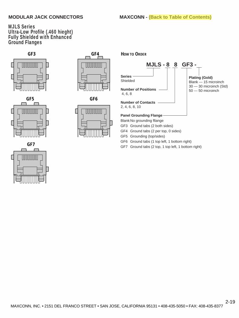
HOW TO ORDER
MJLS - 8 8 GF3 -
SeriesShielded
Number of Positions4, 6, 8
Number of Contacts2, 4, 6, 8, 10
Plating (Gold)Blank — 15 microinch 30 — 30 microinch (Std) 50 — 50 microinch
MAXCONN - (Back to Table of Contents)MODULAR JACK CONNECT ORS
MJLS SeriesUltra-Low Profile (.460 hieght)Fully Shielded with EnhancedGround Flanges
Panel Grounding FlangeBlank No grounding fllangeGF3 Ground tabs (2 both sides)GF4 Ground tabs (2 per top, 0 sides)GF5 Grounding (top/sides)GF6 Ground tabs (1 top left, 1 bottom right)GF7 Ground tabs (2 top, 1 top left, 1 bottom right)
GF3 GF4
GF5 GF6
GF7
MAXCONN, INC. • 2151 DEL FRANCO STREET • SAN JOSE, CALIFORNIA 95131 • 408-435-5050 • FAX: 408-435-83772-19
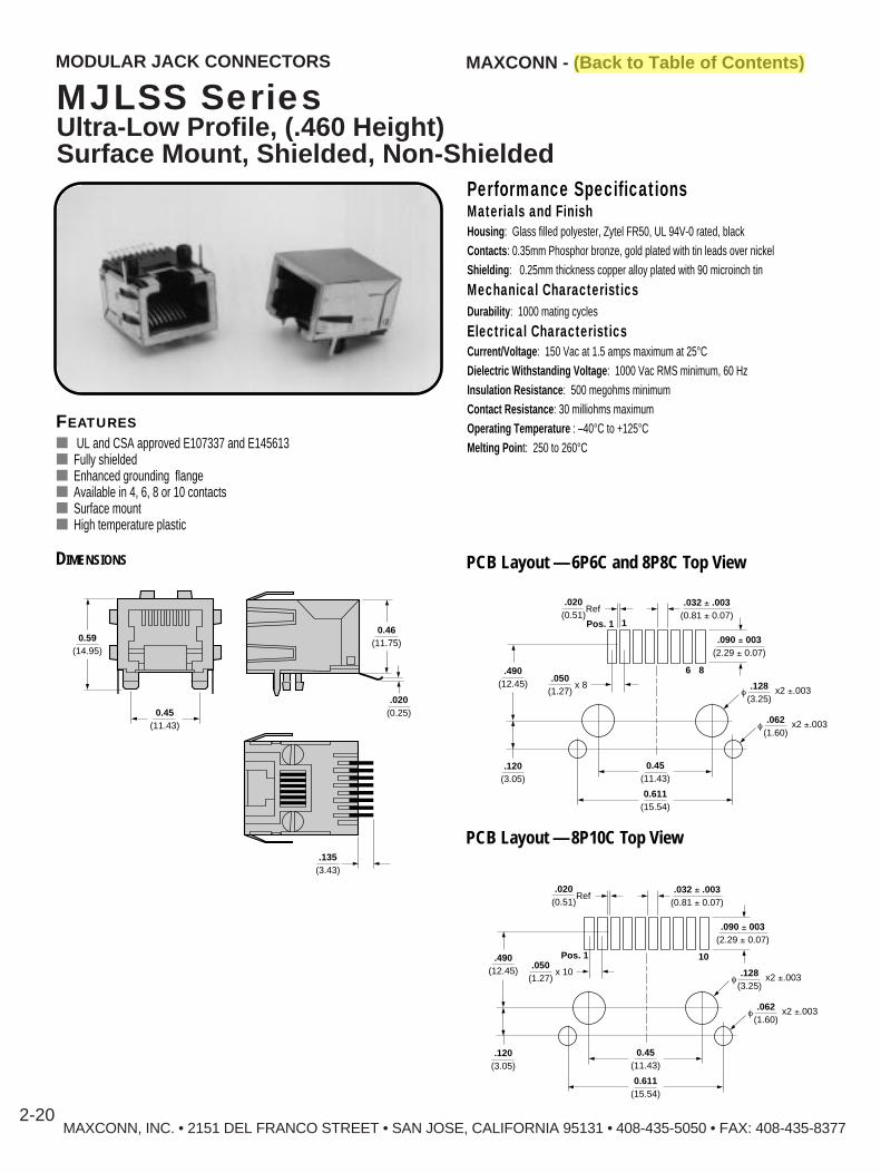
MAXCONN, INC. • 2151 DEL FRANCO STREET • SAN JOSE, CALIFORNIA 95131 • 408-435-5050 • FAX: 408-435-83772-20
MAXCONN - (Back to Table of Contents)MODULAR JACK CONNECT ORS
MJLSS SeriesUltra-Low Profile, (.460 Height)Surface Mount, Shielded, Non-Shielded
FEATURES■ UL and CSA approved E107337 and E145613■ Fully shielded■ Enhanced grounding flange■ Available in 4, 6, 8 or 10 contacts■ Surface mount■ High temperature plastic
Performance SpecificationsMaterials and FinishHousing : Glass filled polyester, Zytel FR50, UL 94V-0 rated, blackContacts : 0.35mm Phosphor bronze, gold plated with tin leads over nickelShielding : 0.25mm thickness copper alloy plated with 90 microinch tin
Mechanical CharacteristicsDurability : 1000 mating cycles
Electrical CharacteristicsCurrent/Voltage : 150 Vac at 1.5 amps maximum at 25°CDielectric Withstanding Voltage : 1000 Vac RMS minimum, 60 HzInsulation Resistance : 500 megohms minimumContact Resistance : 30 milliohms maximumOperating Temperature : –40°C to +125°CMelting Poin t: 250 to 260°C
DIMENSIONS PCB Layout — 6P6C and 8P8C Top View
0.59(14.95)
0.45(11.43)
0.46(11.75)
.020(0.25)
.135(3.43)
.120(3.05)
.490(12.45)
0.45(11.43)
.050(1.27) f
.128(3.25)
x2 ±.003
.090 ± 003(2.29 ± 0.07)
.032 ± .003(0.81 ± 0.07)
.020(0.51)
Ref
x 8
f.062
(1.60)x2 ±.003
0.611(15.54)
8
Pos. 1
6
1
PCB Layout — 8P10C Top View
.120(3.05)
.490(12.45)
0.45(11.43)
.050(1.27) f
.128(3.25)
x2 ±.003
.090 ± 003(2.29 ± 0.07)
.032 ± .003(0.81 ± 0.07)
.020(0.51)
Ref
x 10
f.062
(1.60)x2 ±.003
0.611(15.54)
10Pos. 1

HOW TO ORDER
MJLS - S - 8 8 - ST - GF3 - 30
SeriesShielded
SMTS — Surface monut
Number ofPositions4, 6, 8
Number of Contacts2, 4, 6, 8, 10
PCB OptionsST — Solder TabSTP — Solder tab with PCB locator Blank – Standard through hole pin
Plating (Gold)Blank — 15 microinch 30 — 30 microinch
(Standard) 50 — 50 microinch
MAXCONN - (Back to Table of Contents)MODULAR JACK CONNECT ORS
MJLSS SeriesUltra-Low Profile (.460 hieght)Surface MountFully Shielded and Non-shielded with Enhanced Grounding Flanges
*Panel Grounding FlangeBlank No grounding flangeGF3 Ground tabs (2 both sides)GF4 Ground tabs (2 per top, 0 sides)GF5 Grounding (top/sides)GF6 Ground tabs (1 top left, 1 bottom right)GF7 Ground tabs (2 top, 1 top left, 1 bottom right)
*Panel grounding options only available in 8-position cavity.
GF3
GF5
GF7
GF4
GF6
GF3 GF4
GF5 GF6
GF7
MAXCONN, INC. • 2151 DEL FRANCO STREET • SAN JOSE, CALIFORNIA 95131 • 408-435-5050 • FAX: 408-435-83772-21

MAXCONN - (Back to Table of Contents)MODULAR JACK CONNECT ORS
MJH-C SeriesRJ11/RJ45 Combination,Low Profile, .543 High
MAXCONN, INC. • 2151 DEL FRANCO STREET • SAN JOSE, CALIFORNIA 95131 • 408-435-5050 • FAX: 408-435-83772-22
FEATURES■ Meets FCC and UL specifications■ Low profile .543 Hight■ Non-shielded, shielded■ 1000 mating cycles
Performance SpecificationsMaterials and FinishHousing : Glass filled polyester, UL 94V-0 rated, blackContacts : 0.35mm Phosphor bronze, gold platedShielding : 0.25mm thickness copper alloy plated with 90 microinch tin
Mechanical CharacteristicsDurability : 1000 mating cyclesContact Engagement Force : 1.60 ounces, maximum
Electrical CharacteristicsCurrent/Voltage : 150 Vac at 1.5 amps maximum at 25°CDielectric Withstanding Voltage : 1000 Vac RMS minimum, 60 HzInsulation Resistance : 500 megohms minimumTemperature Rating : -55° C to + 125° C
DIMENSIONS PCB Layout
0.500(12.78)
0.100(2.54) 0.100
(2.54)
0.850(21.59)
0.050(1.27) 0.050
(1.27)
0.108(2.73)
x2
x2
0.500(12.78)
1.215(30.87)
0.35(8.89)
.145(3.68)
0.063(1.60)
f ± .003 x3
0.047(1.20)
f ± .003 x16
0.128(3.25)
f ± .003 x2
.543(13.80)
.132(3.35)
.112(2.85)
0.837(21.27)
0.429(10.89)
0.35(8.89)
0.102(2.60)
.145(3.68)
.675(17.15)
MJH - C - 6 6 / 8 6 - 2B
SeriesBlank – Non-ShieldedS – Shielded
Combination
Number of Positions 6
Number of Contacts2, 4, 6
Positions6
PlatingBlank – 10 microinch gold30 – 30 microinch gold50 – 50 microinch gold
2 Port
Contacts6 or 8
HOW TO ORDER

MAXCONN - (Back to Table of Contents)
MAXCONN, INC. • 2151 DEL FRANCO STREET • SAN JOSE, CALIFORNIA 95131 • 408-435-5050 • FAX: 408-435-8377
MODULAR JACK CONNECT ORS
MJA SeriesRight Angle, PC Mount
FEATURES■ UL and CSA approved E107337 and E145613■ Meets FCC requirements■ Non-shielded■ 4, 6 and 8 positions
2-23
DIMENSIONS
.590(15.00)
.760(19.20)
.6.18(15.70)
.500(12.70) .630
(16.00)
.400(10.16) .050
(1.27)
.250(6.35)
A(20.60).811
(1.27).050
(2.36).093
C
B
f .035(0.89)
f .126(3.20)
D
C
.075(1.905)
.050(1.27)
.350(8.89).100
(2.54)
PCB LAYOUT TOP VIEW
MJA - 4 4 - 30
Series
Number of Positions4, 6, 8
Number of Contacts2, 4, 6, 8
Contact PlatingBlank —6 microinch gold
(Standard)30 — 30 microinch gold50 — 50 microinch gold
HOW TO ORDER
Performance SpecificationsMaterials and FinishHousing : Glass filled polyester, UL 94V-0 rated, blackContacts : 0.35mm Phosphor bronze, gold plated with tin leads
Electrical CharacteristicsCurrent/Voltage : 150 Vac at 1.5 amps maximum at 25°CDielectric Withstanding Voltage : 1000 Vac RMS minimum, 60 HzInsulation Resistance : 500 megohms minimumContact Resistance : 20 milliohms maximumOperating Temperature : -55°C to +125°C
Positions A B C D4 0.540 0.440 0.300 0.150
13.70 11.18 7.62 3.816 0.618 0.520 0.400 0.250
15.70 13.21 10.16 6.358 0.700 0.600 0.450 0.350
17.78 15.24 11.43 8.89

MAXCONN - (Back to Table of Contents)
MAXCONN, INC. • 2151 DEL FRANCO STREET • SAN JOSE, CALIFORNIA 95131 • 408-435-5050 • FAX: 408-435-8377
MODULAR JACK CONNECT ORS
MJB SeriesRight Angle, PC Mount
FEATURES■ UL and CSA approved E107337 and E145613■ Meets FCC requirements■ Non-shielded■ 4, 6 and 8 positions
2-24
DIMENSIONS
.825(20.96)
.125(3.20)
.070(1.78)
.480(12.19)
A
B
E
f .030(0.76)
f .093(2.36)
C
D
.040(1.02)
.024(0.61)
.100(2.54)
PCB LAYOUT TOP VIEW
Performance SpecificationsMaterials and FinishHousing : Glass filled polyester, UL 94V-0 rated, blackContacts : 0.45 mm Phosphor bronze, gold plated round wire
Electrical CharacteristicsCurrent/Voltage : 150 Vac at 1.5 amps maximum at 25°CDielectric Withstanding Voltage : 1000 Vac RMS minimum, 60 HzInsulation Resistance : 500 megohms minimumContact Resistance : 20 milliohms maximumOperating Temperature : -55°C to +125°C
MJB - 4 4 - 30
Series
Number of Positions4, 6, 8
Number of Contacts2, 4, 6, 8
Contact PlatingBlank —6 microinch gold
(Standard)30 — 30 microinch gold50 — 50 microinch gold
HOW TO ORDER
Positions A B C D E4 0.730 0.480 0.625 0.120 0.225
18.54 12.19 15.88 3.06 5.726 0.730 0.480 0.625 0.200 0.225
18.54 12.19 15.88 5.08 5.778 0.730 0.630 0.630 0.280 0.315
18.54 16.00 16.00 7.12 8.00
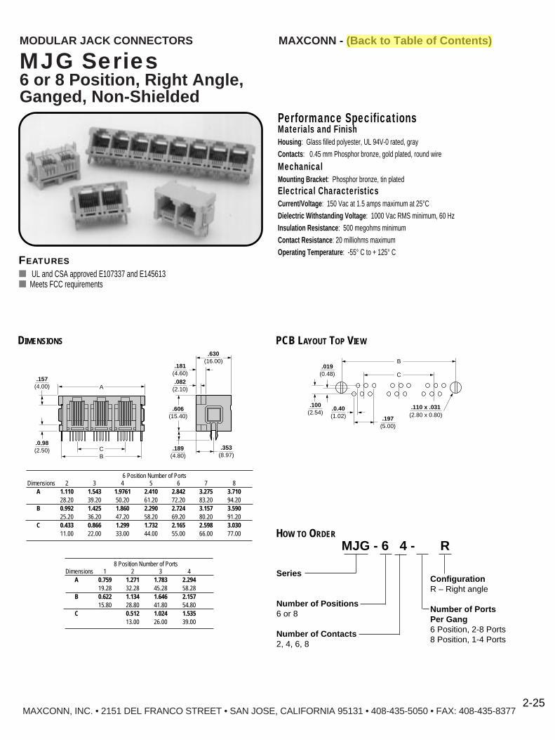
MAXCONN - (Back to Table of Contents)
MAXCONN, INC. • 2151 DEL FRANCO STREET • SAN JOSE, CALIFORNIA 95131 • 408-435-5050 • FAX: 408-435-8377
MODULAR JACK CONNECT ORS
MJG Series6 or 8 Position, Right Angle,Ganged, Non-Shielded
FEATURES■ UL and CSA approved E107337 and E145613■ Meets FCC requirements
2-25
DIMENSIONS
.082(2.10)
.189(4.80)
.353(8.97)
.606(15.40)
.181(4.60)
.157(4.00)
.0.98(2.50)
.630(16.00)
A
CB
.100(2.54)
C
B.019
(0.48)
.110 x .031(2.80 x 0.80)
.197(5.00)
.0.40(1.02)
PCB LAYOUT TOP VIEW
MJG - 6 4 - R
Series
Number of Positions6 or 8
Number of Contacts2, 4, 6, 8
ConfigurationR – Right angle
Number of PortsPer Gang6 Position, 2-8 Ports8 Position, 1-4 Ports
HOW TO ORDER
Performance SpecificationsMaterials and FinishHousing : Glass filled polyester, UL 94V-0 rated, grayContacts : 0.45 mm Phosphor bronze, gold plated, round wire
MechanicalMounting Bracket : Phosphor bronze, tin platedElectrical CharacteristicsCurrent/Voltage : 150 Vac at 1.5 amps maximum at 25°CDielectric Withstanding Voltage : 1000 Vac RMS minimum, 60 HzInsulation Resistance : 500 megohms minimumContact Resistance : 20 milliohms maximumOperating Temperature : -55° C to + 125° C
6 Position Number of PortsDimensions 2 3 4 5 6 7 8
A 1.110 1.543 1.9761 2.410 2.842 3.275 3.71028.20 39.20 50.20 61.20 72.20 83.20 94.20
B 0.992 1.425 1.860 2.290 2.724 3.157 3.59025.20 36.20 47.20 58.20 69.20 80.20 91.20
C 0.433 0.866 1.299 1.732 2.165 2.598 3.03011.00 22.00 33.00 44.00 55.00 66.00 77.00
8 Position Number of PortsDimensions 1 2 3 4
A 0.759 1.271 1.783 2.29419.28 32.28 45.28 58.28
B 0.622 1.134 1.646 2.15715.80 28.80 41.80 54.80
C 0.512 1.024 1.53513.00 26.00 39.00

MAXCONN - (Back to Table of Contents)
MAXCONN, INC. • 2151 DEL FRANCO STREET • SAN JOSE, CALIFORNIA 95131 • 408-435-5050 • FAX: 408-435-8377
MODULAR JACK CONNECT ORS
FEATURES■ UL and CSA approved E107337 and E145613■ Meets FCC requirements
2-26
DIMENSIONS
.082(2.10)
.070(1.78)
.323(8.20)
.342(8.68)
.433(11.00)
.189(4.80)
.138(3.50)
.606(15.40)
.181(4.60)
.157(4.00)
.0.98(2.50)
.630(16.00)
A
C
.100(2.54)
C
B
.019(0.48)
.035(0.90)
.175(3.18).435
(11.00)
PCB LAYOUT TOP VIEW
MJG 6 4 - - V
Series
Number of Positions6 or 8
Number of Contacts2, 4, 6, 8
ConfigurationV – Vertical
Number of PortsPer Gang6 Position, 2-8 Ports8 Position, 1-4 Ports
HOW TO ORDER
Performance SpecificationsMaterials and FinishHousing : Glass filled polyester, UL 94V-0 rated, grayContacts : 0.45 mm Phosphor bronze, gold plated, round wire
MechanicalMounting Bracket : Phosphor bronze, tin platedElectrical CharacteristicsCurrent/Voltage : 150 Vac at 1.5 amps maximum at 25°CDielectric Withstanding Voltage : 1000 Vac RMS minimum, 60 HzInsulation Resistance : 500 megohms minimumContact Resistance : 20 milliohms maximumOperating Temperature : -55° C to + 125° C
6 Position Number of PortsDimensions 2 3 4 5 6 7 8
A 1.110 1.543 1.976 2.410 2.842 3.275 3.71028.20 39.20 50.20 61.20 72.20 83.20 94.20
B 0.992 1.425 1.860 2.290 2.724 3.157 3.59025.20 36.20 47.20 58.20 69.20 80.20 91.20
C 0.433 0.866 1.299 1.732 2.165 2.598 3.03011.00 22.00 33.00 44.00 55.00 66.00 77.00
8 Position Number of PortsDimensions 1 2 3 4
A 0.759 1.271 1.783 2.29419.28 32.28 45.28 58.28
B 0.622 1.134 1.646 2.15715.80 28.80 41.80 54.80
C 0.512 1.024 1.53513.00 26.00 39.00
MJG Series6 or 8 Position, V ertical, Ganged, Non-Shielded

Performance SpecificationsMaterials and FinishHousing : Glass filled polyester, UL 94V-0 rated, blackContacts : Phosphor bronze, gold platedElectrical CharacteristicsCurrent/Voltage : 150 Vac at 1.5 amps maximum at 25°CDielectric Withstanding Voltage : 1000 Vac RMS minimum, 60 HzInsulation Resistance : 500 megohms minimumContact Resistance : 30 milliohms maximumOperating Temperature : -55° C to + 125° C
MJF - 4 4 - 30
Series
Number of Positions4, 6, 8
Number of Contacts2, 4, 6, 8
Contact PlatingBlank —6 microinch gold
(Standard)30 — 30 microinch gold50 — 50 microinch gold
HOW TO ORDER
MAXCONN - (Back to Table of Contents)
MAXCONN, INC. • 2151 DEL FRANCO STREET • SAN JOSE, CALIFORNIA 95131 • 408-435-5050 • FAX: 408-435-8377
MODULAR JACK CONNECT ORS
MJF SeriesRight Angle, PC Mount
FEATURES■ UL and CSA approved E107337 and 145613■ Meets FCC requirements■ Non-shielded
2-27
DIMENSIONS
����
0.099(2.50)
0.356(9.05)
0.399(10.14)
0.681(17.30)
BA
0.750(19.06)
3.25(0.128)
C
Dia.
0.89(0.035)
0.625(0.024)
6.55(0.258)
9.05(0.356)
1.25(0.049)
Dia.
PCB LAYOUT TOP VIEW
Positions A B C4 0.570 0.810 0.288
14.48 20.57 7.316 0.650 0.810 0.388
16.51 20.57 9.858 0.730 0.810 0.488
18.54 20.57 12.39

MODULAR JACK CONNECT ORS
MJM SeriesRight Angle, PC Mount
MAXCONN - (Back to Table of Contents)
FEATURES■ Meets FCC specifications■ UL, and CSA approved E107337 and E145613■ Top latch
Performance SpecificationsMaterials and FinishHousing : Glass filled polyester, UL 94V-0 rated, grayContacts : 0.45mm Phosphor bronze, gold plated, round wire
Mechanical CharacteristicsContact Engagement Force : 1.60 ounces, maximum
Electrical CharacteristicsCurrent/Voltage : 150 Vac at 1.5 amps maximum at 25°CDielectric Withstanding Voltage : 1000 Vac RMS minimum, 60 HzInsulation Resistance : 500 megohms minimumOperatingTemperature : -55° C to + 125° C
DIMENSIONS
MJM 6P4C (Shown)0.480
(12.20)
0.571(14.50)
0.125(3.20)
0.236(6.00)
0.472(12.00)
0.125(3.20)
0.040(1.02)
0.201(5.10)
DIMENSIONS
MJM 6P6C (Shown)0.480
(12.20)
0.571(14.50)
0.125(3.20)
0.236(6.00)
0.472(12.00)
0.125(3.20)
0.040(1.02)
0.201(5.10)
.472(12.0)f .091
(2.30)x2
f .031(0.79)
x6
.091(2.30)
.040(1.02)
.201(5.10)
.100(2.54)6
Pos. 1
.472(12.0)f .091
(2.30)x2
f .031(0.79)
x4
.091(2.30)
.040(1.02)
.121(3.06)
.100(2.54)
4
Pos. 1
PCB Layout6 Positions, 4 Contacts 6 Positions, 6 Contacts MJM - 8 8 F - 2
Series
Number of Positions4, 6, 8
Number of Contacts2, 4, 6, 8
Contact Plating1 — 10 microinch gold
(Standard)2 — 30 microinch gold3 — 50 microinch gold
CableBlank — Without flangeF — Flange
HOW TO ORDER
MAXCONN, INC. • 2151 DEL FRANCO STREET • SAN JOSE, CALIFORNIA 95131 • 408-435-5050 • FAX: 408-435-83772-28

MAXCONN - (Back to Table of Contents)
MAXCONN, INC. • 2151 DEL FRANCO STREET • SAN JOSE, CALIFORNIA 95131 • 408-435-5050 • FAX: 408-435-8377
MODULAR JACK CONNECT ORS
MJP SeriesVertical, PC Mount
FEATURES■ UL and CSA approved E107337 and E145613■ Meets FCC requirements■ Non-shielded■ 4, 6 and 8 positions
2-29
DIMENSIONS
.625(15.88)
.100(2.54)
.130(3.30)
.645(16.38)
A
B
.157(4.00) C
.100(2.54)
f .035(0.89)
f .125(3.18) C
D
.050(1.27)
.350(8.89)
PCB LAYOUT TOP VIEW
Performance SpecificationsMaterials and FinishHousing : Glass filled polyester, UL 94V-0 rated, blackContacts : 0.45 mm phosphor bronze, gold plated, round wire
Electrical CharacteristicsCurrent/Voltage : 150 Vac at 1.5 amps maximum at 25°CDielectric Withstanding Voltage : 1000 Vac RMS minimum, 60 HzInsulation Resistance : 500 megohms minimumContact Resistance : 20 milliohms maximumOperating Temperature : -55°C to +125°C
MJP - 4 4 - 30
Series
Number of Positions4, 6, 8
Number of Contacts2, 4, 6, 8
Contact PlatingBlank — 6 microinch gold
(Standard)30 — 30 microinch gold50 — 50 microinch gold
HOW TO ORDER
Positions A B C D4 0.550 0.450 0.300 0.150
13.97 11.43 7.62 3.816 0.630 0.530 0.400 0.250
16.00 13.46 10.16 6.358 0.70 0.605 0.465 0.350
17.84 15.36 11.80 8.89
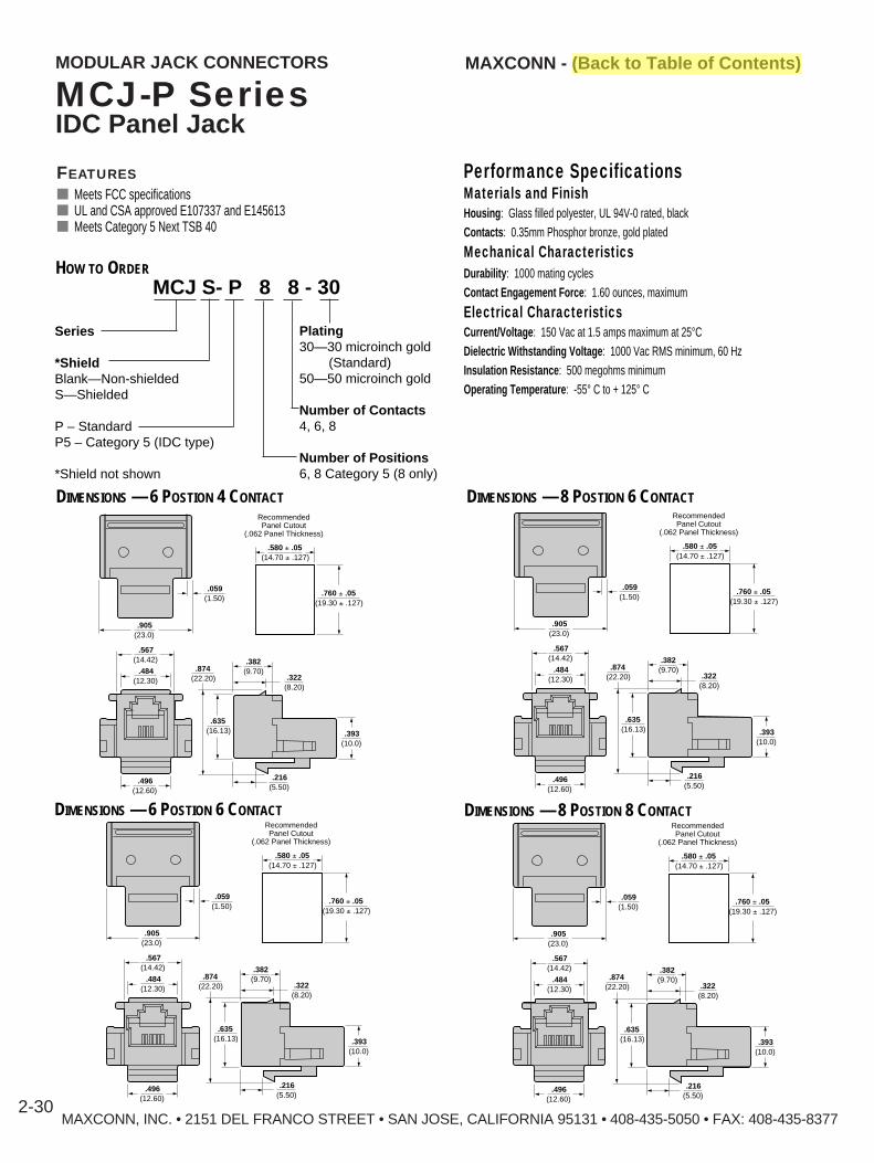
MAXCONN, INC. • 2151 DEL FRANCO STREET • SAN JOSE, CALIFORNIA 95131 • 408-435-5050 • FAX: 408-435-83772-30
MODULAR JACK CONNECT ORS
MCJ-P SeriesIDC Panel Jack
MAXCONN - (Back to Table of Contents)
FEATURES■ Meets FCC specifications■ UL and CSA approved E107337 and E145613■ Meets Category 5 Next TSB 40
Performance SpecificationsMaterials and FinishHousing : Glass filled polyester, UL 94V-0 rated, blackContacts : 0.35mm Phosphor bronze, gold plated
Mechanical CharacteristicsDurability : 1000 mating cyclesContact Engagement Force : 1.60 ounces, maximum
Electrical CharacteristicsCurrent/Voltage : 150 Vac at 1.5 amps maximum at 25°CDielectric Withstanding Voltage : 1000 Vac RMS minimum, 60 HzInsulation Resistance : 500 megohms minimumOperating Temperature : -55° C to + 125° C
DIMENSIONS — 6 POSTION 4 CONTACT
.580 ± .05
RecommendedPanel Cutout
(.062 Panel Thickness)
(14.70 ± .127)
.760 ± .05(19.30 ± .127)
.905(23.0)
.484(12.30) .322
(8.20)
.382(9.70)
.496(12.60)
.567(14.42)
.874(22.20)
.635(16.13) .393
(10.0)
.216(5.50)
.059(1.50)
DIMENSIONS — 8 POSTION 6 CONTACT
.580 ± .05
RecommendedPanel Cutout
(.062 Panel Thickness)
(14.70 ± .127)
.760 ± .05(19.30 ± .127)
.905(23.0)
.484(12.30) .322
(8.20)
.382(9.70)
.496(12.60)
.567(14.42)
.874(22.20)
.635(16.13) .393
(10.0)
.216(5.50)
.059(1.50)
.580 ± .05
RecommendedPanel Cutout
(.062 Panel Thickness)
(14.70 ± .127)
.760 ± .05(19.30 ± .127)
.905(23.0)
.484(12.30) .322
(8.20)
.382(9.70)
.496(12.60)
.567(14.42)
.874(22.20)
.635(16.13) .393
(10.0)
.216(5.50)
.059(1.50)
.580 ± .05
RecommendedPanel Cutout
(.062 Panel Thickness)
(14.70 ± .127)
.760 ± .05(19.30 ± .127)
.905(23.0)
.484(12.30) .322
(8.20)
.382(9.70)
.496(12.60)
.567(14.42)
.874(22.20)
.635(16.13) .393
(10.0)
.216(5.50)
.059(1.50)
DIMENSIONS — 6 POSTION 6 CONTACT DIMENSIONS — 8 POSTION 8 CONTACT
MCJ S- P 8 8 - 30
Series
*ShieldBlank—Non-shieldedS—Shielded
P – StandardP5 – Category 5 (IDC type)
*Shield not shown
HOW TO ORDER
Plating30—30 microinch gold
(Standard)50—50 microinch gold
Number of Contacts4, 6, 8
Number of Positions6, 8 Category 5 (8 only)

MAXCONN - (Back to Table of Contents)MODULAR JACK COUPLERS
MJC-88 SeriesModular Jack CouplerNon-Shielded, Shielded
MAXCONN, INC. • 2151 DEL FRANCO STREET • SAN JOSE, CALIFORNIA 95131 • 408-435-5050 • FAX: 408-435-83772-31
FEATURES■ Meets FCC requirements■ Non-shielded, shielded■ 6 and 8 position cavity sizes■ UL and CSA approved E107337 and E145613
DIMENSIONS0.573
Side Rear Face
(14.55)Pin 1
Panel Face
Pin 1
0.579(14.73)
Non-ShieldedRecommendedPanel Cutout
0.640(16.25)
0.640(16.25)
0.630
Side Rear Face
(16.00)Pin 1
Front Face
Pin 1
0.866(21.99)
0.573
Side Rear Face
(14.55)Pin 1
Panel Face
Pin 1
0.579(14.73)
ShieldedRecommendedPanel Cutout
0.640(16.25)
0.740(18.80)
WiringDiagram
1 12 23 34 45 56 67 78 8
WiringDiagramInverse
1 82 73 64 55 46 37 28 1
MJC S - 88 - 1 - 0 - 30
SeriesNP – Non-panel series
(Inverse only)S – Shielded
(Panel mount only)
Number ofPositions/Contacts6P4C, 6P6C, 8P8C
WiringBlank – 1 to 11 – Inverse (non-panel mount only)
Gold PlatingBlank –10 microinch30 – 30 microinch
(Standard)50 – 50 microinch
Color (Non-shielded)0– Black1 – Beige2 – Red4 – Yellow5 – Green9 – White
HOW TO ORDER
Performance SpecificationsMaterials and FinishHousing : Glass filled polyester, UL 94V-0 rated, blackContacts : 0.35mm phosphor bronze, gold platedShielding : 0.25mm thickness copper alloy plated with 90 microinch tin
Mechanical CharacteristicsDurability : 1000 mating cycles
Electrical CharacteristicsCurrent/Voltage : 150 Vac at 1.5 amps maximum at 25°CDielectric Withstanding Voltage : 1000 Vac RMS minimum, 60 HzInsulation Resistance : 500 megohms minimumContact Resistance : 30 milliohms maximumOperating Temperature : -55°C to +125°C
WiringDiagram
1 12 23 34 45 56 67 78 8

MP SeriesNon-Shielded, Shielded
FEATURES■ UL and CSA approved E107337 and E145613■ Meets FCC requirements■ Flat and round cable■ Shielded 6P, 8P and 8P10C
Performance SpecificationsMaterials and FinishHousing : Polycarbonate UL 94V-0 ratedContacts : Phosphor bronzeContact Finish : Gold plated
Mechanical CharacteristicsDurability : 1,000 mating cycles
Electrical CharacteristicsCurrent/Voltage : 150Vac at 1.5 Amps at 25°CDielectric Withstanding Voltage : 1,000 Vac RMS minimum, 60 HzInsulation Resistance : 500 megohms minimumContact Resistance : 30 milliohms maximumOperating Temperature : -40° C to + 60° C
DIMENSIONS
MP88 Non-Shielded8 Positions, 8 Contacts
.287(7.29)
.312(7.92)
.109(2.77)
.895(22.73)
.052(1.32)
.040(1.02)
.232(5.89)
.128
.460(11.68)
Flat Cable Entry Round Cable Entry
.240(6.1)
(3.25)
MAXCONN, INC. • 2151 DEL FRANCO STREET • SAN JOSE, CALIFORNIA 95131 • 408-435-5050 • FAX: 408-435-8377
MAXCONN - (Back to Table of Contents)MODULAR PLUG CONNECT ORS
2-32
MPS88 Shielded8 Positions, 8 Contacts
MP810 Non-Shielded8 Positions, 10 Contacts
MPS810 Shielded8 Positions, 10 Contacts
.287(7.29)
.312(7.92)
.109(2.77)
.895(22.73)
.052(1.32)
.040(1.02)
.232(5.89)
.128
.460(11.68)
Round Cable Entry
.240(6.1)
(3.25)
.287(7.29)
.312(7.92)
.109(2.77)
.895(22.73)
.052(1.32)
.040(1.02)
.232(5.89)
.460(11.68)
Flat Cable Entry Round Cable Entry
.128
.240(6.1)
(3.25)
��������.287
(7.29).312
(7.92)
.109(2.77)
.895(22.73)
.052(1.32)
.040(1.02)
.232(5.89)
.128
.460(11.68)
Round Cable Entry
.240(6.1)
(3.25)
�����

MAXCONN, INC. • 2151 DEL FRANCO STREET • SAN JOSE, CALIFORNIA 95131 • 408-435-5050 • FAX: 408-435-8377
MAXCONN - (Back to Table of Contents)
2-33
MP44 Non-Shielded4 Positions, 4 Contacts
MP66 Non-Shielded6 Positions, 6 Contacts
.287(7.29)
.260(6.6)
.109(2.77)
FlatCable Entry
Round Cable Entry
.525(13.34)
.052(1.32)
.040(1.02)
.232(5.89)
.100(2.54)
.300(7.62)
.195(4.95)
.287(7.29)
.260(6.6)
.109(2.77)
FlatCable Entry
Round Cable Entry
.525(13.34)
.052(1.32)
.040(1.02)
.232(5.89)
.128
.380(9.65)
.240(6.1)
(3.25)
MP SeriesNon-Shielded, Shielded
Dimensions
MODULAR PLUG CONNECT ORS
MP - 8 8 F - 30
SeriesBlank – UnshieldedS* – Shielded 6P and 8P onlyNumber of Positions4, 6, 8
Number of Contacts2, 4, 6, 8, 10**Available in 6P and 8P only
Contact PlatingBlank–10 microinch gold30–30 microinch gold50–50 microinch gold
CableF – FlatR – Round
HOW TO ORDER

MAXCONN - (Back to Table of Contents)MODULAR JACK CONNECT ORS
MAXCONN, INC. • 2151 DEL FRANCO STREET • SAN JOSE, CALIFORNIA 95131 • 408-435-5050 • FAX: 408-435-8377
Performance SpecificationsMaterials and FinishDielectric Body : PVC thermoplastic, UL 94V-0 rated
FEATURES■ UL and CSA approved E107337 and E145613■ RJ45 8-position cable boot■ With or without latch cover■ Strain relief options■ Various color code
MP8B SeriesCable Boots with andwithout Latch Protectors
HOW TO ORDER
MP8B — — — X
Series
Type
DIMENSIONS
0.555(14.10)
Side view
Dia.
Front view
0.453(11.51)
0.236(6.00)
0.315(8.00)
0.413(10.50)
0.610(15.50)
2-34
Option andCable Exit
Color Code
0.555(14.10)
Side view
Dia.
Front view
0.315(8.00)
0.469(11.90)
0.236(6.00)
0.295(7.50)
0.413(10.50)
0.524(13.30)
Side view Front view
0.197(5.00)
0.398(10.10)
0.413(10.50)
0.071(1.80)
0.045(1.16)
0.394(10.00)
0.445(11.30)
0.555(14.10)
Side view Front view
0.469(11.90)
0.374(9.50)
0.413(10.50)
0.469(11.90)
( )
Side view Front view
0.591(15.00)
(10.50)0.413
0.071(1.80)
0.394(10.00)
0.445(11.30)
MP8B-SRF
MP8B-SRMP8B
MP-8P
MP8B-T
MP8B-SRF-T

MAXCONN - (Back to Table of Contents)MODULAR JACK CONNECT ORS
MP SeriesMale Cable Assembly
FEATURES■ Custom pin out■ Category 5■ UL and CSA approved
Length
P1 P2Pin 1
Pin 8
Pin 1
Pin 8
MP_ - 4 2 F - - 1 - 0
SeriesBlank – UnshieldedS – Shielded(8 position only)
Number of Positions4, 6, 8
Contacts2, 4, 6, 8, 10**Available 8P only
CableF – Flat cableR – Round cableR5 – Category 5
ColorBlank – Silver satin0 – Black1 – Beige
Length (Feet)
HOW TO ORDER
MAXCONN, INC. • 2151 DEL FRANCO STREET • SAN JOSE, CALIFORNIA 95131 • 408-435-5050 • FAX: 408-435-83772-35
DIMENSIONS
Wiring Diagram1 – 1-1 (standard)2 – 1-8XX – Factory assigned
Pin-OutWiring
DiagramPositions P1 P2
1 _ _2 _ _3 _ _4 _ _5 _ _6 _ _7 _ _8 _ _9 _ _
10 _ _


MFPC Series - 1.00mm Right Angle Surface Mount, Vertical Contact 3-2
MAXCONN, INC. - 2151 DEL FRANCO STREETo SAN JOSE, CALIFORNIA 95131 - 408-435-5050,, FAX: 408-435-8377MAXCONN EUROPE. - Edlingerstr. 3 - D-81543 Munich/München Tel: 49 (0) 89-65 11 30 88, Fax: 49 (0) 89-65 11 30 88
E-Mail: [email protected] - Web: http://www.eucon-elektronik.com
Flat Flex CircuitConnectors

MAXCONN - (Back to Table of Contents)
MAXCONN, INC. • 2151 DEL FRANCO STREET • SAN JOSE, CALIFORNIA 95131 • 408-435-5050 • FAX: 408-435-8377
Features■ UL and CSA approved E107377 and E145613■ Low profile construction surface mount■ High temperature■ Top, Bottom and vertical mounted
MFPC Series1.00mm Right AngleSurface Mount, V erticalContact
DIMENSIONS
0.011 ± .002(0.30 ± 0.05) 0.039 ± .003
No. 1 Contact Locator
Connector Bottom VIew
Actuator Open
Actuator Closed
Vertical Entry
(1.00 ± 0.10)A
0.007 ± .003(0.20 ± 0.10)
Bottom EntryTop Entry
0.29 ± .003(7.54 ± 0.10)
0.051 ± .002(1.30 ± 0.05)
0.216 ± .003(0.55 ± 0.10)
0.033 ± .003(0.85 ± 0.10)
0.112 ± .003(2.85 ± 0.10)
0.130 ± .003(3.30 ± 0.10)
0.354(9.00)
B
C
D
0.134 ± .003(3.40 ± 0.10)
.208 ± .003(5.30 ± .10)
0.059 ± .003(1.50 ± 0.10)
0.013 ± .002(0.35 ± 0.10)
0.007 ± .003(0.20 ± 0.05)
PERFORMANCE SPECIFICATIONSMaterials and FinishHousing : Nylon 6T, UL94V-0 RatedActuator : PPS (Brown Color)Contact : Phosphor bronzeContact Solder Tab : BrassContact Finish : Minimum 0.0020 tin/leadSolder Tab : Minimum 0.0015 tin plated
3-2
HOW TO ORDER
MFPC – XX – X – X – X
Series
Number of Positions3 — 32
TypeR – Right anglev – Vertical
TypeX – Vertical entry*T – Top entry*B – Bottom entry*Pertains to right angle type only
PlatingT – Tin plated
FLAT FLEX CIRCUIT CONNECTORS

Number of DimensionsPositions A B C D
±.0004 ±.0006 ±.0006 ±.0006±0.010 ±0.015 ±0.015 ±0.015
3 0.078 0.161 0.307 03852.00 4.10 7.80 9.80
4 0.118 0.200 0.346 0.4253.00 5.10 8.80 10.80
5 0.157 0.240 0.385 0.4644.00 6.10 9.80 11.80
6 0.197 0.279 0425 0.5045.00 7.10 10.80 12.80
7 0.236 0.319 0.464 0.5046.00 8.10 11.80 13.80
8 0.275 0.358 0.504 0.5837.00 9.10 12.80 14.80
9 0.315 0.397 0.543 0.6228.00 10.10 13.80 15.80
10 0.354 0.437 0.583 0.6619.00 11.10 14.80 16.80
11 0.393 0.476 0.622 0.70010.00 12.10 15.80 17.80
12 0.433 0.515 0.661 0.74011.00 13.10 16.80 18.80
13 0.472 0.555 0.700 0.77912.00 14.10 17.80 19.80
14 0.512 0.594 0.740 0.81813.00 15.10 18.80 20.80
15 0.551 0.633 0.779 0.85814.00 16.10 19.80 21.80
16 0.590 0.673 0.818 0.89715.00 17.10 20.80 22.80
17 0.629 0.712 0.858 0.93716.00 18.10 21.80 23.80
MAXCONN - (Back to Table of Contents)FLAT FLEX CIRCUIT CONNECTORS
MAXCONN, INC. • 2151 DEL FRANCO STREET • SAN JOSE, CALIFORNIA 95131 • 408-435-5050 • FAX: 408-435-83773-3
Number of DimensionsPositions A B C D
±.0004 ±.0006 ±.0006 ±.0006±0.010 ±0.015 ±0.015 ±0.015
18 0.669 0.752 0.897 0.97617.00 19.10 22.80 24.80
19 0.708 0.791 0.937 1.01518.00 20.10 23.80 25.80
20 0.748 0.830 0.976 1.05519.00 21.10 24.80 26.80
21 0.787 0.870 1.015 1.09420.00 22.10 25.80 27.80
22 0.826 0.909 1.055 1.13321.00 23.10 26.80 28.80
23 0.866 0.948 1.094 1.17322.00 24.10 27.80 29.80
24 0.905 0.988 1.133 1.21223.00 25.10 28.80 30.80
25 0.945 1.027 1.173 1.25224.00 26.10 29.80 31.80
26 0.984 1.066 1.212 1.29125.00 27.10 30.80 32.80
27 1.023 1.106 1.252 1.33026.00 28.10 31.80 33.80
28 1.062 1.114 1.291 1.37027.00 29.10 32.80 34.80
29 1.102 1.185 1.330 1.40928.00 30.10 33.80 35.80
30 1.141 1.224 1.370 1.44829.00 31.10 34.80 36.80
31 1.181 1.263 1.409 1.48830.00 32.10 35.80 37.80
32 1.220 1.303 1.448 1.52731.00 33.10 36.80 38.80
MFPC Series1.00mm Right Angle, Surface Mouent,Vertical Contact


5210, 5220 Series - 0.05 (1.27 mm) Centers, Single and Dual Row 7-2
5S210, 5S220 Series - 0.05 (1.27 mm) Centers, Surface Mount, Single and Dual Row 7-3
5410, 5420 Series - 0.05 (1.27 mm) Centers Single and Dual Row 7-4
5S410, 5S420 Series - 0.05 (1.27 mm) Centers, Surface Mount, Single and Dual Row 7-5
2M210, 2M220 Series - 0.079 (2 mm) Centers Single and Dual Row 7-6
2MS220 Series - 0.079 (2mm) Centers, Surface Mount, Dual Row 7-7
2M21013S, 2M22013S Series - 0.079 (2mm) Centers Single and Dual Row 7-8
2M410, 2M420 Series - 0.079 (2 mm) Centers Single and Dual Row 7-9
2MS420 Series - 0.079 (2 mm) Surface Mount, Dual Row, 6 to 60 Positions 7-10
210, 220, 230 Series - 0.1 (2.54 mm) Centers Single, Dual and Three Row 7-11
21013S, 220BS Series - 0.1 (2.54 mm) Centers Single and Dual Row 7-13
410, 420 Series - 0.1 (2.54 mm.) Centers Single and Dual Row 7-14
EH Series - 0.1 (2.54 mm.) Centers Dual Row 7-15SH Series - 0.1 (2.54 mm) Centers Dual Row 7-16320 Series - 0.1 (2.54 mm) Centers Dual Row 7-17S100, S200, S300 Series - 0.1 (2.54 mm) Centers 7-18S9 Series - 0.1 (2.54 mm) Centers 7-19
MAXCONN, INC. - 2151 DEL FRANCO STREETo SAN JOSE, CALIFORNIA 95131 - 408-435-5050,, FAX: 408-435-8377MAXCONN EUROPE. - Edlingerstr. 3 - D-81543 Munich/München Tel: 49 (0) 89-65 11 30 88, Fax: 49 (0) 89-65 11 30 88
E-Mail: [email protected] - Web: http://www.eucon-elektronik.com
Headers

MAXCONN - (Back to Table of Contents)
7-2MAXCONN, INC. • 2151 DEL FRANCO STREET • SAN JOSE, CALIFORNIA 95131 • 408-435-5050 • FAX: 408-435-8377
MAXCONN
5210, 5220 Series0.05 (1.27mm) Centers, Single and Dual Row
PERFORMANCE SPECIFICATIONSMaterials and FinishDielectric Body : PBT thermoplastic, black color, 30% glass filled, self-extinguishing,
94V-0 ratedContact Material : Brass Contact Finish : 1 – Tin: 100 microinch tin over 70 microinch copper
Gold: 2 – 10 microinch gold over 50 microinch nickel3 – 15 microinch gold over 50 mircoinch nickel4 – 30 microinch gold over 50 microinch nickel
Electrical CharacteristicsContact Current Rating : 3 ampsContact Resistance : 10 milliohms maximumDielectric Withstanding Voltage : 1000VrmsInsulation Resistance : 5,000 megohms minimumTemperature Rating : -55° C to + 125° C
Mechanical CharacteristicsPin Push-Out Force : 3 lbs
HOW TO ORDER
5210 V — B 40 — 2���
0.10(2.54)
.110(2.80)
.100(2.54)
.102(2.60)
.110(2.80)
.100(2.54)
.102(2.60)
0.098(2.50)
0.20(5.00)
FEATURES
■ Stack headers end-to-end or side-to-side without loss of positions■ Easy breakaway to required size■ Tin or three types of gold plating options■ Single row, 1-32 positions■ Dual row, 2-80 positions
(1.27) (0.46)0.0180.05
(1.27)0.05
(1.27)0.05
Pin
(0.51) +0.01–0.00
+0.0004–0.00
Dia.
Sq.
0.02Pin
x No. of Contacts
x No. of Positions
DIMENSIONS — SINGLE AND DUAL ROW
Single Row Dual Row
Code Plating Options
1 100 microinch tin
2 10 microinch gold
3 15 microinch gold
4 30 microinch gold
Series5210- Single Row5220- Dual Row
Pin TypeV – Vertical Pins
MaterialBrass Number of
Contacts Per Row1-32, SIngle Row2-40, Dual Row
HEADERS

MAXCONN, INC. • 2151 DEL FRANCO STREET • SAN JOSE, CALIFORNIA 95131 • 408-435-5050 • FAX: 408-435-8377
MAXCONN - (Back to Table of Contents)
5S210, 5S220 Series0.05 (1.27mm) Centers, SurfaceMount, Single and Dual Row
7-3
Performance SpecificationsMaterials and FinishDielectric Body : PBT thermoplastic, black color, 30% glass filled, self-extinguishing,
94V-0 ratedContact Material : Brass Contact Finish : 1 – Tin: 100 microinch tin over 70 microinch copper
Gold: 2 – 10 microinch gold over 50 microinch nickel3 – 15 microinch gold over 50 mircoinch nickel4 – 30 microinch gold over 50 microinch nickel
Electrical CharacteristicsContact Current Rating : 3 ampsContact Resistance : 10 milliohms maximumDielectric Withstanding Voltage : 1000VrmsInsulation Resistance : 5,000 megohms minimumTemperature Rating : -55° C to + 125° C
Mechanical CharacteristicsPin Push-Out Force : 3 lbs
FEATURES
■ Ideal for board stacking applications■ Notches for easy breakaway■ Single row, 1 to 32 positions■ Dual row, 2 to 80 positions
HOW TO ORDER
5S210 - 32 - V - 2
Series5S210 – Single row5S220 – Dual row
Number of ContactsPer Row1 to 32 Single Row2 to 40 Dual Row
Connector TypeV – Vertical
(1.27) (0.46)0.0180.05
(1.27)0.05
(1.27)0.05
(1.27)0.05
Pin
(0.51) +0.01–0.00
+0.0004–0.00
Dia.
Sq.
0.02Pin
x No. of Contacts –
x No. of Positions
DIMENSIONS – SINGLE AND DUAL ROW
0.098
0.20(5.00)
(2.54)0.10
0.05(1.27)
0.198(5.04)
0.29(7.54)
(2.50)
.110(2.80)
.100(2.54)
.110(2.80)
.100(2.54)
0.05(1.27)
Single Row Dual Row
Code Plating Options
1 100 microinch tin
2 10 microinch gold
3 15 microinch gold
4 30 microinch gold
.220(5.50)
0.76(.030)
.100(2.54) (1.27)
.050
0.76(.030)
.220(5.50)
.295(7.49)
.245(6.22)
PCB LAYOUT — RECOMMENDED
Single Row Dual Row
HEADERS

MAXCONN - (Back to Table of Contents)HEADERS
7-4MAXCONN, INC. • 2151 DEL FRANCO STREET • SAN JOSE, CALIFORNIA 95131 • 408-435-5050 • FAX: 408-435-8377
MAXCONN
5410, 5420 Series0.05 (1.27mm) CentersSingle and Dual Row
FEATURES
■ Low profile and high density is suitable for devices which require small and light internal parts
■ High reliability contact structure provides normal-force after repeated cycles■ Mating with 1.27mm pitch 0.46mm square pin headers■ Single row 2 to 50 positions■ Dual row 4 to 100 positions
Performance SpecificationsMaterials and FinishDielectric Body : PBT thermoplastic, black color, 30% glass filled, self-extinguishing,
94V-0 ratedContact Material : Phosphor bronzeContact Finish : 1 – Tin: 100 microinch tin over 70 microinch copper
2 – 10 microinch gold over 50 microinch nickel3 – 15 microinch gold over 50 mircoinch nickel4 – 30 microinch gold over 50 microinch nickel
Electrical CharacteristicsContact Current Rating : 3 ampsContact Resistance : 10 milliohms maximumDielectric Withstanding Voltage: 1000 Vdc minimumInsulation Resistance : 5,000 megohms minimumTemperature Rating : -55° C to + 125° CPin Push-Out Force : 3 lbs
(1.27)
(1.27)
0.05
(1.27)0.05
(0.46)0.018
0.05
Pin Dia.
x No. of Contacts
x No. of Positions
DIMENSIONS – SINGLE AND DUAL ROW
0.098 0.20(5.10)
0.118(3.00)
0.02 0.02(0.50) (0.50)
f 0.04(1.00)
0.14(3.50)
0.024(6.10)
(2.50)
0.23(6.00)
0.23(6.00)
Single Row Dual Row
HOW TO ORDER
5410 - 40 - 2Series5410 Single Row5420 Dual Row
Number of ContactsPer Row5410 – 2 to 50 Single Row5420 – 4 to 100 Dual Row
Code Plating Options
1 100 microinch tin
2 10 microinch gold
(Standard)
3 15 microinch gold
4 30 microinch gold

MAXCONN - (Back to Table of Contents)HEADERS
MAXCONN, INC. • 2151 DEL FRANCO STREET • SAN JOSE, CALIFORNIA 95131 • 408-435-5050 • FAX: 408-435-83777-5
5S410, 5S420 Series0.05 (1.27mm) Centers, SurfaceMount, Single and Dual Row
FEATURES
■ Low profile: 6.0mm height■ Dual beam phosphor bronze contacts■ Designed for board to board small spacing interconnection■ Mating with 1.27mm pitch 0.46mm square headers■ Single row – 4 to 50 positions■ Dual row – 8 to 60 positions
Performance SpecificationsMaterials and FinishDielectric Body : PBT thermoplastic, black color, 30% glass filled, self-extinguishing,
94V-0 ratedContact Material : Phosphor bronzeContact Finish : 1 – Tin: 100 microinch tin over 70 microinch copper
Gold: 2 – 10 microinch gold over 50 microinch nickel3 – 15 microinch gold over 50 mircoinch nickel4 – 30 microinch gold over 50 microinch nickel
Electrical CharacteristicsContact Current Rating : 3 ampsContact Resistance : 10 milliohms maximumDielectric Withstanding Voltage: 1000 Vdc minimumInsulation Resistance : 5,000 megohms minimumTemperature Rating : -55° C to + 125° CPin Push-Out Force : 3 lbs
(1.27)
(0.23 +1.27)
0.05
(1.27)0.05
(5.80)0.22
(1.20).047
(0.42 x 0.2).016 x 0.08
.009 + 0.05
Pin
Optional Locating Peg
Dia.
x No. of Contacts
x No. of Positions
DIMENSIONS – SINGLE AND DUAL ROW
0.098 0.20(5.10)
0.118(3.00)
0.02 0.02(0.50) (0.50)
f 0.04(1.00)
0.14(3.50)
0.024(6.10)
(2.50)
0.23(6.00)
0.23(6.00)
Single Row Dual Row
HOW TO ORDER
5S410 - 40 - 2Series5S410 Single Row5S420 Dual Row
Number of ContactsPer Row5410 –4 to 50 Single Row5420 –8 to 60 Dual Row
PCB LAYOUT – RECOMMENDED
DUAL ROW
.047
.025(0.63)
.080(2.03)
.100(2.54)
(1.19)Typ
.050(1.27)
.025(0.63)
f
.200(5.08)
Code Plating Options
1 100 microinch tin
2 10 microinch gold
3 15 microinch gold
4 30 microinch gold
Blank – Without PegL – With Peg
SINGLE ROW.025(0.63)
.080(2.03)
.100(2.54)
.050(1.27)

MAXCONN - (Back to Table of Contents)MALE HEADERS
MAXCONN, INC. • 2151 DEL FRANCO STREET • SAN JOSE, CALIFORNIA 95131 • 408-435-5050 • FAX: 408-435-83777-6
2M210, 2M220 Series0.079 (2mm) CentersSingle and Dual Row
HOW TO ORDER
2M210 V - B 10 A - 2
FEATURES
■ 0.020 (0.50mm) square contact post■ 0.079 (2mm) centers between post spacing■ Stack headers end to end or side to side without loss of positions■ Mates with 0.079 x 0.079 grid female connector■ Single row from 1 to 40 positions■ Dual row from 2 to 40 positions■ ANy pin can be void of gold plating option■ Tin or three types of gold plating options■ Any pin length available to 3.5 inches maximum
�.079
(2.00)
.147(3.68)
.079(2.00)
x No. of Contacts
.079(2.00)
.079(2.00)
x No. of Positions
.020(0.50)
Contacts End:�.144
(3.68)
.039(1.0).039
(1.0)
.079(2.00)
.118(3.00)
.118(3.00)
DIMENSIONS — SINGLE ROW
Series2M210 – SIngle row2M220 – Dual row
Type of PinsV – Vertical pinsR – Right angle pins
B – Brass
Number ofContacts per Row2M210 – 40 maximum2M220 – 40 per row
Performance SpecificationsMaterials and FinishDielectric Body : PBT thermoplastic, black color, 30% glass filled, self-extinguishing,
94V-0 ratedContact Material : BrassContact Finish : Tin: 100 microinch tin over 70 microinch copper
Gold: (A) 10 microinch gold over 50 microinch nickel(B) 15 microinch gold over 50 mircoinch nickel(C) 30 microinch gold over 50 microinch nickel
Electrical CharacteristicsContact Current Rating : 3 ampsContact Resistance : 10 milliohms maximumDielectric Withstanding Voltage : 1000VrmsInsulation Resistance : 5,000 megohms minimumTemperature Rating : -55° C to + 125° C
Mechanical CharacteristicsPin Push-Out Force : 3 lbs
.079(2.00)
.079(2.00)
x No. of Contacts
.079(2.00)
.079(2.00)
x No. of Positions
.020(0.50)
Contacts End:
�.118
(3.00)
.144(3.68)
.079(2.00)
�.144(3.68)
.079(2.00)
.157(4.0)
DIMENSIONS — DUAL ROW
Configuration Code Dimensions
A B
Vertical A 0.118 0.145
Right Angle C 0.149 0.295
Vertical/Rt Angle X Any pin length available to3.5 inches maximum(upon request)
Code Plating Options
1 100 microinch tin
2 10 microinch gold
3 15 microinch gold
4 30 microinch gold

MALE HEADERS
MAXCONN, INC. • 2151 DEL FRANCO STREET • SAN JOSE, CALIFORNIA 95131 • 408-435-5050 • FAX: 408-435-8377
Series
Type of PinsV – Vertical Pins
B – Brass
Number of Contacts per Row
Pin Length(0.157 inches)
2MS220 Series0.079 (2mm) Centers, Surface Mount, Dual Row
MAXCONN - (Back to Table of Contents)
7-7
HOW TO ORDER
2MS220 V - B - 40 A - 2
PERFORMANCE SPECIFICATIONSMaterials and FinishDielectric Body : PBT thermoplastic, black color, 30% glass filled, self-extinguishing,
94V-0 ratedContact Material : Brass
Contact Finish : Tin: 100 microinch tin over 70 microinch copperGold: (A) 10 microinch gold over 50 microinch copper
(B) 15 microinch gold over 50 mircoinch copper(C) 30 microinch gold over 50 microinch copper
Electrical CharacteristicsContact Current Rating : 3 ampsContact Resistance : 10 milliohms maximumDielectric Withstanding Voltage : 1000VrmsInsulation Resistance : 5,000 megohms minimumTemperature Rating : -55° C to + 125° C
Mechanical CharacteristicsPin Push-Out Force : 3 lbs
FEATURES
■ 0.02 (0.50mm) square contact post■ 0.079 (2mm) centers between post spacing■ Stack headers end to end or side to side without loss of positions■ Mates with 0.079 x 0.079 grid female connector■ Dual row from 4 to 50 positions per row■ Any pin can be void of polarization■ Tin or three types of gold plating options■ Any pin length to 3.5 inches maximum
0.15(4.00)
(2.00) (0.5 x 0.5).02 x .020.079
(2.00)0.079
(2.00)0.079
Pin
(0.3 x 0.5).011 x .02Pin
Optical Locating Peg
x No. of Contacts
A
0.06(1.50)
0.079(2.00)
0.18(4.80)
x No. of Positions
DIMENSIONS
Code Plating Options
1 100 microinch tin
2 10 microinch gold
3 15 microinch gold
4 30 microinch gold
.079 ± .002(2.00 ± 0.05)
.080(2.03)
.180 ± .002(4.57 ± 0.05)
.035 ± .002(4.57 ± 0.05)
PCB LAYOUT
Blank – Without Locating PegL – With Locating Peg

MAXCONN - (Back to Table of Contents)
MAXCONN, INC. • 2151 DEL FRANCO STREET • SAN JOSE, CALIFORNIA 95131 • 408-435-5050 • FAX: 408-435-8377
Series2M210BS – Single Row2M220BS – Double Row
ContactsV – Vertical
ContactsB – Brass
Number of ContactsPer Row
7-8
2M210BS, 2M220BS Series0.079 (2mm) CentersSingle and Dual Row
FEATURES
■ 0.020 (0.50mm) square contact post■ 0.079 (2mm) centers between post spacing■ Single row from 2 to 40 positions■ Dual row from 4 to 80 positions■ Tin or three types of gold plating options■ Side and end stackable (on unbroken edges)■ Notches for easy breakage■ Maintains dimension between two PC boards■ Standoffs facilitate post soldering clean
�0.079
B
C
A
(2.00)
0.079(2.00)
x No. of Positions
0.079(2.00)
0.079(2.00)
0.079(2.00)
x No. of Positions
0.020(0.50)
Contacts End:
DIMENSIONS – 2M210BS SINGLE ROW DIMENSIONS – 2M220BS DUAL ROW
�BC
A
x No. of Contacts
0.079(2.00)
0.079(2.00)
0.079(2.00)
0.079(2.00)
0.15(4.00)
0.079(2.00)
x No. of Positions
0.020(0.50)
Contacts End:
Performance SpecificationsMaterials and FinishDielectric Body : PBT thermoplastic, black color, 30% glass filled, self-extinguishing,
94V-0 ratedContact Material : BrassContact Finish : Tin: 100 microinch tin over 70 microinch copper
Gold: (A) 10 microinch gold over 50 microinch nickel(B) 15 microinch gold over 50 mircoinch nickel(C) 30 microinch gold over 50 microinch nickel
Electrical CharacteristicsContact Current Rating : 1 ampContact Resistance : 10 milliohms maximumDielectric Withstanding Voltage : 630Vdc minimumInsulation Resistance : 5,000 megohms minimumTemperature Rating : -55° C to + 125° C
HOW TO ORDER
2M210BS - V - B 40 - .XXX -.XXX - .XXX - 2
Code Plating Options
1 100 microinch tin
2 10 microinch gold
3 15 microinch gold
4 30 microinch gold
Dimension C
Dimension B
Dimension A
HEADERS

MAXCONN - (Back to Table of Contents)
7-9MAXCONN, INC. • 2151 DEL FRANCO STREET • SAN JOSE, CALIFORNIA 95131 • 408-435-5050 • FAX: 408-435-8377
HEADERS
2M410, 2M420 Series0.079 (2mm) Centers Single and Dual Row
Performance SpecificationsMaterials and FinishDielectric Body : PBT thermoplastic, black color, 30% glass filled, self-extinguishing,
94V-0 ratedContact Material : Phosphor bronzeContact Finish : Tin: 100 microinch tin over 70 microinch copper
Gold: (A) 10 microinch gold over 50 microinch nickel(B) 15 microinch gold over 50 mircoinch nickel(C) 30 microinch gold over 50 microinch nickel
Electrical CharacteristicsContact Current Rating : 3 ampsContact Resistance : 10 milliohms maximumDielectric Withstanding Voltage : 1000Vdc minimumInsulation Resistance : 5,000 megohms minimumTemperature Rating : -55° C to + 125° C
Mechanical CharacteristicsPin Push-Out Force : 3 lbs
FEATURES■ Low profile: 4.3mm height■ Designed for parallel and vertical board stacking■ Mating with 2.0mm grid, dual row male header■ 4-80 positions
DIMENSIONS – 2M420 DUAL ROW
DIMENSIONS – SINGLE ROW
2M410 – TOP ENTRY
(2.00) (0.5 x 0.2)0.02 x .0080.08
(2.00)0.08
(2.00)0.08
Pin
x No. Contacts –
(0.4 + 2.0).016 + 0.08 x No. of Positions
0.06(1.50)
0.17(4.50)
0.12(3.00)
0.79(2.00)
(0.45)0.02 .161
(4.10)
0.06(1.50)
0.17(4.30)
0.12(3.00)
(0.45)0.02
0.20(5.00)
0.18(4.60)
0.06(1.50)
0.16(4.30)
0.12(3.00)
(0.45)0.02
0.24(6.00)
0.18(4.60)
0.06(1.50)
.177(4.50)
.126(3.00)
(0.45)0.02 .079
(2.00)
2.0 Pin 0.5 x 0.2
2.0 x Number of Contacts
0.7 x 2.0 x Number of Positions
DIMENSIONS – 2M420 TOP ENTRY
DIMENSIONS – 2M421 TOP/BOTTOM ENTRY
DIMENSIONS – 2M422 TOP/BOTTOM ENTRY
HOW TO ORDER
2M410 - 10 - 2
Code Plating Options
1 100 microinch tin
2 10 microinch gold
3 15 microinch gold
4 30 microinch gold
Series2M410 – Single row top entry2M420 – Dual row top entry
2mm between rows2M421 – Dual row top/bottom entry
5mm between rows2M422 – Dual row top/bottom entry
6mm between rows
Number of Contacts per RowSingle – 2 to 40Dual – 4 to 80

MAXCONN - (Back to Table of Contents)HEADERS
7-10MAXCONN, INC. • 2151 DEL FRANCO STREET • SAN JOSE, CALIFORNIA 95131 • 408-435-5050 • FAX: 408-435-8377
MAXCONN
2MS420 Series0.079 (2mm) Surface Mount,Dual Row , 6 to 60 Positions
FEATURES
■ Low profile: 4.1mm height■ Dual beam phosphor bronze contacts■ Designed for board to board small spacing interconnection■ Mating with 1.27mm pitch 0.46mm square headers
0.06(1.50)
0.047(1.20)
Optional Locating Peg
0.16(4.10)
0.04(1.0)
f
0.17(4.30)
(0.5 x 0.2).02 x .008Pin
0.08(2.00)
0.23(6.00)
0.31(8.00)
0.16(4.00) 0.23
(6.00)
0.16(4.00)
0.08(2.00)
DIMENSIONS
HOW TO ORDER
2MS420 - 60 - 1Series2MS420
Number ofContacts6 to 60
Performance SpecificationsMaterials and FinishDielectric Body : PBT thermoplastic, black color, 30% glass filled, self-extinguishing,
94V-0 ratedContact Material : Phosfor BronzeContact Finish : 1 Tin: 100 microinch tin over 70 microinch copper
Gold: 2 – 10 microinch gold over 50 microinch nickel3 – 15 microinch gold over 50 mircoinch nickel4 – 30 microinch gold over 50 microinch nickel
Electrical CharacteristicsContact Current Rating : 3 ampsContact Resistance : 10 milliohms maximumDielectric Withstanding Voltage : 1000VrmsInsulation Resistance : 5,000 megohms minimumTemperature Rating : -55° C to + 125° C
Mechanical CharacteristicsPin Push-Out Force : 3 lbs
Code Plating Options
1 100 microinch tin
2 10 microinch gold
3 15 microinch gold
4 30 microinch gold
Blank – Without Locating PegL – With Locating Peg
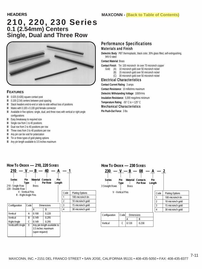
MAXCONN, INC. • 2151 DEL FRANCO STREET • SAN JOSE, CALIFORNIA 95131 • 408-435-5050 • FAX: 408-435-8377
MAXCONN - (Back to Table of Contents)
7-11
210, 220, 230 Series0.1 (2.54mm) CentersSingle, Dual and Three Row
Performance SpecificationsMaterials and FinishDielectric Body : PBT thermoplastic, black color, 30% glass filled, self-extinguishing,
94V-0 ratedContact Material : BrassContact Finish : Tin: 100 microinch tin over 70 microinch copper
Gold: (A) 10 microinch gold over 50 microinch nickel(B) 15 microinch gold over 50 mircoinch nickel(C) 30 microinch gold over 50 microinch nickel
Electrical CharacteristicsContact Current Rating : 3 ampsContact Resistance : 10 milliohms maximumDielectric Withstanding Voltage : 1000VrmsInsulation Resistance : 5,000 megohms minimumTemperature Rating : -55° C to + 125° C
Mechanical CharacteristicsPin Push-Out Force : 3 lbs
FEATURES
■ 0.025 (0.635) square contact post■ 0.100 (2.54) centers between post spacing■ Stack headers end-to-end or side-to-side without loss of positions■ Mates with 0.100 x 0.100 grid female connector■ Available in five options: single, dual, and three rows with vertical or right angle
configurations■ Easy breakaway to required size■ Single row from 1 to 40 positions■ Dual row from 2 to 40 positions per row■ Three rows from 3 to 40 positions per row■ Any pin can be void for polarization■ Tin or three types of gold plating options■ Any pin length available to 3.5 inches maximum
HOW TO ORDER — 210, 220 SERIES
210 — V — B — 40 — A — 1
Series Pin Material Contacts PinType Per Row Length
210 - Single Row Brass220 - Double Row
V - Vertical PinsR - Right Angle Pins
Configuration Code Dimensions
A B
Vertical A 0.100 0.220
Vertical B 0.149 0.295
Right Angle C 0.149 0.295Vertical/Rt Angle X Any pin length available to
3.5 inches maximum(upon request)
Code Plating Options
1 100 microinch tin
2 10 microinch gold
3 15 microinch gold
4 30 microinch gold
HOW TO ORDER — 230 SERIES
230 — V — B — 08 — A — 2
Series Pin Material Contacts PinType Per Row Length
3 Straight Rows Brass
V - Vertical Pins
Configuration Code Dimensions
A B
Vertical C 0.120 0.230
Code Plating Options
1 100 microinch tin
2 10 microinch gold
3 15 microinch gold
4 30 microinch gold
HEADERS

MAXCONN - (Back to Table of Contents)
MAXCONN, INC. • 2151 DEL FRANCO STREET • SAN JOSE, CALIFORNIA 95131 • 408-435-5050 • FAX: 408-435-83777-12
210, 220, 230 Series0.1 (2.54mm) CentersSingle, Dual and Three Row
Mounting Options210V SeriesSingle Row , Straight
�.100
(2.54)
.100(2.54)
.100(2.54)
.100(2.54)
x No. of Positions
.100(2.54)
x No. of Positions
.025(0.64)
Solder End:
.025(0.64)
Contacts End:
.118(3.00)
.236(6.00)
220V SeriesDual Row , Straight
�.100
(2.54).100
(2.54)
.100(2.54)
.100(2.54)
.200(5.08)
.100(2.54)
x No. Positions
.100(2.54)
x No. of Positions
.025(0.64)
Sq.Solder End:
.025(0.64)
Sq.Contact End:
.236(6.00)
.118(3.00)
210R SeriesSingle Row , Right Angle
�.100
(2.54) .100(2.54)
.120(3.05)
.236(6.00)
.118(3.00)
220R SeriesDual Row , Right Angle
�.200
(5.08)
.059(1.50)
.236(6.00)
.118(3.00)
230 SeriesThree Row , Straight
�.100(2.54)
.100(2.54)
0.20(5.08)
.100(2.54)
.100(2.54)
x No. Positions
.100(2.54)
0.03(7.62)
x No. of Positions
.025(0.64)
Contacts End:
.025(0.64)
Solder End:
.118(3.00)
.236(6.00)
HEADERS

MAXCONN - (Back to Table of Contents)
MAXCONN, INC. • 2151 DEL FRANCO STREET • SAN JOSE, CALIFORNIA 95131 • 408-435-5050 • FAX: 408-435-8377
210BS, 220BS Series0.1 (2.54mm) CentersSingle and Dual Row
7-13
FEATURES
■ 0.025 (0.635) square contact post■ 0.100 (2,54) centers between post spacing■ Single row from 2 to 40 positions■ Dual row from 4 to 80 positions■ Tin or three types of gold plating options■ Side and end stackable (on unbroken edges)■ Notches for easy breakage■ Maintains dimension between two PC boards■ Standoffs facilitate post soldering cleaning
Performance SpecificationsMaterials and FinishDielectric Body : PBT thermoplastic, black color, 30% glass filled, self-extinguishing,
94V-0 ratedContact Material : BrassContact Finish : Tin: 100 microinch tin over 70 microinch copper
Gold: (A) 10 microinch gold over 50 microinch nickel(B) 15 microinch gold over 50 mircoinch nickel(C) 30 microinch gold over 50 microinch nickel
Electrical CharacteristicsContact Current Rating : 1 ampContact Resistance : 10 milliohms maximumDielectric Withstanding Voltage : 500 Vdc minimumInsulation Resistance : 5,000 megohms minimumTemperature Rating : -55° C to + 125° C
�.100
B
C
A
(2.54)
.100(2.54)
x No. of Positions
.100(2.54)
.100(2.54)
.098(2.50)
x No. of Positions
.025(0.64)
Contacts End:
�.100
B
C
A
(2.54)
.100(2.54)
x No. of Positions
.100(2.54)
.100(2.54)
0.20(5.08)
x No. of Positions
.025(0.64)
Contacts End:
DIMENSIONS – 210BS (SINGLE ROW) DIMENSIONS – 220BS (DUAL ROW)
HOW TO ORDER
210BS - V - B 40 - .XXX -.XXX - .XXX - 2Series210BS – Single Row220BS – Dual Row
ContactsV – Vertical
ContactsB – Brass
Number of ContactsPer Row
Code Plating Options
1 100 microinch tin
2 10 microinch gold
3 15 microinch gold
4 30 microinch gold
Dimension C
Dimension B
Dimension A
HEADERS

MAXCONN - (Back to Table of Contents)HEADERS
7-14MAXCONN, INC. • 2151 DEL FRANCO STREET • SAN JOSE, CALIFORNIA 95131 • 408-435-5050 • FAX: 408-435-8377
410, 420 Series0.1 (2.54mm) Centers Single and Dual Row
PERFORMANCE SPECIFICATIONSMaterials and FinishDielectric Body : PBT thermoplastic, black color, 30% glass filled, self-extinguishing,
94V-0 ratedContact Material : Phosphor bronzeContact Finish : 1 – Tin: 100 microinch tin over 70 microinch copper
Gold: 2 – 10 microinch gold over 50 microinch nickel3 – 15 microinch gold over 50 mircoinch nickel4 – 30 microinch gold over 50 microinch nickel
Electrical CharacteristicsContact Current Rating : 3 ampsContact Resistance : 10 milliohms maximumDielectric Withstanding Voltage : 1000Vdc minimumInsulation Resistance : 5,000 megohms minimumTemperature Rating : -55° C to + 125° C
Mechanical CharacteristicsPin Push-Out Force : 3 lbs
FEATURES■ Mates with 0.025 (0.635mm) square contact post■ Available in four options: single or dual rows, with straight tails■ Single row from 4 to 86 positions■ Dual row from 4 to 40 positions■ 0.100 x 0.100 grid
.100
0.5 + 2.54 x No. of positions
2.54 x No. of positions – 2.54
(2.54)
.200(5.08)
DIMENSIONS – 420 DUAL ROW
HOW TO ORDER
410 - 40 - 1
Code Plating Options
1 100 microinch tin
2 10 microinch gold
3 15 microinch gold
4 30 microinch gold
Series410 – Single row top entry420 – Dual row top entry
2.54mm between rows421 – Dual row top/bottom entry
3.81mm between rows422 – Dual row top/bottom entry
5.08mm between rows423 – Dual row top/bottom entry
7.62mm between rows
Number of Contacts per RowSingle – 2 to 40Dual – 4 to 80
DIMENSIONS – 410 SINGLE ROW
410 – TOP ENTRY
420 – TOP ENTRY
421 – TOP/BOTTOM ENTRY
422 – TOP/BOTTOM ENTRY
423 – TOP/BOTTOM ENTRY
.050(1.27)
.094(2.40)
.332(8.45)
.110(2.8)
.100(2.54)
Pin 0.7 x 0.4
2.54 x No. of Contacts
0.5 + 2.54 x No. of Positions
.165 ± .007(4.2 ± 0.2)
.200(5.08)
.150(3.81)
.197(5.00)
.197* Se(5.00)
.200(5.08)
.200(5.08)
.197(5.00)
.197(5.00)
.100(2.54)
.332(8.43)
.332(8.43)
.200(5.08)
.300(7.62)
.197(5.00)
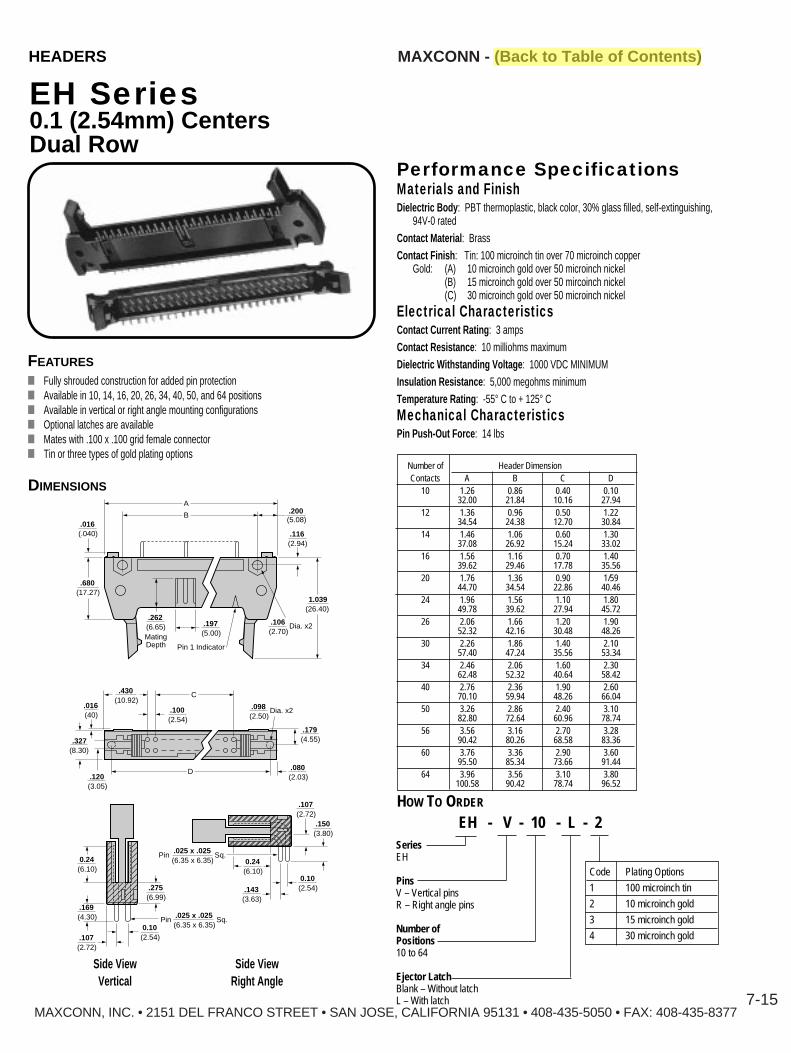
MAXCONN, INC. • 2151 DEL FRANCO STREET • SAN JOSE, CALIFORNIA 95131 • 408-435-5050 • FAX: 408-435-8377
MAXCONN - (Back to Table of Contents)
7-15
EH Series0.1 (2.54mm) CentersDual Row
FEATURES
■ Fully shrouded construction for added pin protection■ Available in 10, 14, 16, 20, 26, 34, 40, 50, and 64 positions■ Available in vertical or right angle mounting configurations■ Optional latches are available■ Mates with .100 x .100 grid female connector■ Tin or three types of gold plating options
.200(5.08)
.116(2.94)
.106(2.70)
.197(5.00)
.100(2.54)
.179(4.55)
.080(2.03).120
(3.05)
.327(8.30)
.016(40)
.430(10.92)
.016(.040)
.262(6.65)MatingDepth Pin 1 Indicator
Dia. x2
.098(2.50)
Dia. x2
.680(17.27)
1.039(26.40)
B
C
D
A
DIMENSIONS
���
(2.72).107
(2.72).107
(2.54)
Pin Sq.0.10
(2.54)0.10
(3.63).143
(3.80).150
(6.10)0.24
(6.10)0.24
(6.99).275
(6.35 x 6.35).025 x .025
Pin Sq.(6.35 x 6.35).025 x .025
(4.30).169
Side ViewVertical
Side ViewRight Angle
HOW TO ORDER
EH - V - 10 - L - 2SeriesEH
PinsV – Vertical pinsR – Right angle pins
Number ofPositions10 to 64
Ejector LatchBlank – Without latchL – With latch
Performance SpecificationsMaterials and FinishDielectric Body : PBT thermoplastic, black color, 30% glass filled, self-extinguishing,
94V-0 ratedContact Material : BrassContact Finish : Tin: 100 microinch tin over 70 microinch copper
Gold: (A) 10 microinch gold over 50 microinch nickel(B) 15 microinch gold over 50 mircoinch nickel(C) 30 microinch gold over 50 microinch nickel
Electrical CharacteristicsContact Current Rating : 3 ampsContact Resistance : 10 milliohms maximumDielectric Withstanding Voltage : 1000 VDC MINIMUMInsulation Resistance : 5,000 megohms minimumTemperature Rating : -55° C to + 125° C
Mechanical CharacteristicsPin Push-Out Force : 14 lbs
Code Plating Options
1 100 microinch tin
2 10 microinch gold
3 15 microinch gold
4 30 microinch gold
Number of Header DimensionContacts A B C D
10 1.26 0.86 0.40 0.1032.00 21.84 10.16 27.94
12 1.36 0.96 0.50 1.2234.54 24.38 12.70 30.84
14 1.46 1.06 0.60 1.3037.08 26.92 15.24 33.02
16 1.56 1.16 0.70 1.4039.62 29.46 17.78 35.56
20 1.76 1.36 0.90 1/5944.70 34.54 22.86 40.46
24 1.96 1.56 1.10 1.8049.78 39.62 27.94 45.72
26 2.06 1.66 1.20 1.9052.32 42.16 30.48 48.26
30 2.26 1.86 1.40 2.1057.40 47.24 35.56 53.34
34 2.46 2.06 1.60 2.3062.48 52.32 40.64 58.42
40 2.76 2.36 1.90 2.6070.10 59.94 48.26 66.04
50 3.26 2.86 2.40 3.1082.80 72.64 60.96 78.74
56 3.56 3.16 2.70 3.2890.42 80.26 68.58 83.36
60 3.76 3.36 2.90 3.6095.50 85.34 73.66 91.44
64 3.96 3.56 3.10 3.80100.58 90.42 78.74 96.52
HEADERS

MAXCONN - (Back to Table of Contents)
MAXCONN, INC. • 2151 DEL FRANCO STREET • SAN JOSE, CALIFORNIA 95131 • 408-435-5050 • FAX: 408-435-8377
SH Series0.1 (2.54mm) CentersDual Row
7-16
FEATURES
■ Fully shrouded construction for added pin protection■ Available in 10, 14, 16, 20, 26, 34, 40, 50, 60, 64 positions■ Available in vertical or right angle mounting configurations■ Low profile■ Mates with .100 x .100 grid female connector■ Tin or three types of gold plating options
HOW TO ORDER
SH - V - 10 - 1
Series
Pin StyleV – Vertical pinsR – Right angle pins
Number ofPositions10 to 64(See table)
.197
.350(8.89)
.017(.43)
(5.00).270
(6.84)MatingDepth
ArrowMarks
Position 1
.203(5.15).159
(4.05)
B
A
.017(.43)
.330(8.37)
.250(6.35)
DIMENSIONS
.157(4.00)
.100(2.54)
.118(3.00)
.118(3.00).100
(2.54)
.100(2.54)
.045(1.15)
Side ViewVertical
Side ViewRight Angle
No. of Header DimensionsPins A B10 0.80 0.40
20.30 10.1612 0.90 0.50
22.84 12.7014 1.00 0.60
25.38 15.2416 1.10 0.70
27.92 17.7820 1.30 0.90
33.00 22.8624 1.50 1.10
38.08 27.9426 1.60 1.20
40.62 30.4830 1.80 1.40
45.70 35.56
No. of Header DimensionsPins A B34 2.00 1.60
50.78 40.6440 2.30 1.90
58.40 48.2644 2.50 2.10
63.48 53.3450 2.80 2.40
71.10 60.9656 3.10 2.70
78.72 68.5860 3.30 2.90
83.80 73.6664 3.50 3.10
88.88 78.74
Performance SpecificationsMaterials and FinishDielectric Body : PBT thermoplastic, black color, 30% glass filled, self-extinguishing,
94V-0 ratedContact Material : BrassContact Finish : Tin: 100 microinch tin over 70 microinch copper
Gold: (A) 10 microinch gold over 50 microinch nickel(B) 15 microinch gold over 50 mircoinch nickel(C) 30 microinch gold over 50 microinch nickel
Electrical CharacteristicsContact Current Rating : 3 ampsContact Resistance : 10 milliohms maximumDielectric Withstanding Voltage : 1000VacInsulation Resistance : 5,000 megohms minimumTemperature Rating : -55° C to + 125° C
Mechanical CharacteristicsPin Push-Out Force : 14 lbs
Code Plating Options
1 100 microinch tin
2 10 microinch gold
3 15 microinch gold
4 30 microinch gold
HEADERS

HEADERS
MAXCONN, INC. • 2151 DEL FRANCO STREET • SAN JOSE, CALIFORNIA 95131 • 408-435-5050 • FAX: 408-435-8377
MAXCONN - (Back to Table of Contents)
7-17
320 Series0.1 (2.54mm) Centers Dual Row
Performance SpecificationsMaterials and FinishDielectric Body : PBT thermoplastic, black color, 30% glass filled, self-extinguishing,
94V-0 ratedContact Material : BrassContact Finish : Tin: 100 microinch tin over 70 microinch copper
Gold: (A) 10 microinch gold over 50 microinch nickel(B) 15 microinch gold over 50 mircoinch nickel(C) 30 microinch gold over 50 microinch nickel
Electrical CharacteristicsContact Current Rating : 3 ampsContact Resistance : 10 milliohms maximumDielectric Withstanding Voltage : 1000VrmsInsulation Resistance : 5,000 megohms minimumTemperature Rating : -55° C to + 125° C
Mechanical CharacteristicsPin Push-Out Force : 14 lbs
FEATURES
■ Large plastic body for added mechanical stability and strength■ 0.025 (0.635mm) square contact post■ 0.100 (2.54mm) centers between post spacing■ Mates with 0.100 x 0.100 grid female connector■ Available in dual rows with vertical or right angle configuration■ Tin or three types of gold plating options■ Dual row from 2 to 80 positions
(1.37)0.35
(1.37)0.35
(7.00).275
(7.40).291
(3.55).140
(6.32).249
(3.55).140
(3.55).140
(6.32).249
(2.54)
Front View Front View
Side View Side View
.100
(6.32).249
(7.00).275
(7.40).291
(3.55).140
(2.54).100
(2.54).100
(2.25).167
(2.25).167
(7.40).291
(2.54).100
DIMENSIONS HOW TO ORDER
320 — V — B — 40 — 1
Series320 – Dual Row
Pin TypeV– Vertical PinsR – Right Angle Pins
MaterialB – Brass
Number of Contacts Per Row
Code Plating Options
1 100 microinch tin
2 10 microinch gold
3 15 microinch gold
4 30 microinch gold
VerticalRight Angle

MAXCONN - (Back to Table of Contents)
MAXCONN, INC. • 2151 DEL FRANCO STREET • SAN JOSE, CALIFORNIA 95131 • 408-435-5050 • FAX: 408-435-8377
MAXCONN
S100, S200, S300 Series0.1 (2.54mm) Centers
FEATURES
■ Low or high insertion force is available■ Low or high profile is available■ Black or blue colors (other colors are available upon request)■ Mate with 0.025 (0.635) square contact post on 0.100 centers■ Unique dual leaf contact gives balanced forces and low resistance■ Chamfered entry for mating alignment■ Fully stackable side to side or end to end without loss of positions■ Tin of three types of gold plating options■ Open top to accommodate mating with long contact post
�.197
.236(6.00)
.096(2.44)
(5.00)
.145(3.68)
MatingDepth
.100(2.54)
DIMENSIONS — S100 SERIES
HIGH PROFILE, LOW INSERTION FORCE
HOW TO ORDER
S100 0 - T - 2SeriesS100S200S300
Color0 – Black6 – Blue
TabsBlank – Without tabT – With tab�
(5.00).197
.236(6.00)
.105(2.66)
MatingDepth
.096(2.44)
.100(2.54)
S200 SERIES
HIGH PROFILE, HIGH INSERTION FORCE
�(4.98).196
.177(4.50)
.067(1.70)
MatingDepth
.096(2.44)
.100(2.54)
S300 SERIES
LOW PROFILE, LOW INSERTION FORCE
(5.00).197
(2.54).100
.531(13.5)
S100 -T SERIES
PERFORMANCE SPECIFICATIONSMaterials and FinishDielectric Body : PBT thermoplastic, black color, 30% glass filled, self-extinguishing,
94V-0 ratedContact Material : Phosfor BronzeContact Finish : Tin: 100 microinch tin over 70 microinch copper
Gold: (A) 10 microinch gold over 50 microinch nickel(B) 15 microinch gold over 50 mircoinch nickel(C) 30 microinch gold over 50 microinch nickel
Electrical CharacteristicsContact Current Rating : 2 ampsContact Resistance : 10 milliohms maximumDielectric Withstanding Voltage : 630Vdc minimumInsulation Resistance : 5,000 megohms minimumTemperature Rating : -55° C to + 125° C
Mechanical CharacteristicsSeries Nominal Nominal
Contact ContactSeparation Engangement
Force ForceS100 4 ounce 4 ounceS200 5 ounce 7 ounceS300 4 ounce 4 ounce
Code Plating Options
1 100 microinch tin
2 10 microinch gold
3 15 microinch gold
4 30 microinch gold
7-18
HEADERS

MAXCONN, INC. • 2151 DEL FRANCO STREET • SAN JOSE, CALIFORNIA 95131 • 408-435-5050 • FAX: 408-435-8377
MAXCONN - (Back to Table of Contents)
7-19
DIMENSIONS
S9 Series0.1 (2.54mm) Centers
FEATURES
■ Two to ten positions■ Mates with 0.025 (0.635) square contact post on 0.100 centers■ Unique dual leaf contact gives balanced forces and low resistance■ Fully stackable side to side or end to end without loss of positions■ Tin or three types of gold plating options■ Open top to accommodate mating with long contact post
HOW TO ORDER
S9 08 0 - 2SeriesS9
Number ofShunts2 to 10
Color0 – Black
��(4.57 ± 0.200).180 ± 0.008 (6.09 ± 0.200)
A
.240 ± 0.008
(.630 ± 0.200).025 ± 0.008
(3.81 ± 0.200).150 ± 0.008
(.630 ± 0.200).025 ± 0.008
(5.00 ± 0.200).200 ± 0.008
(2.54 ± 0.200)Centers
.100 ± 0.008(.760 ± 0.200).030 ± 0.008 No. of Dimensions
Shunts A2 0.3003 0.4004 0.5005 0.6006 0.7007 0.8008 0.9009 1.000
10 1.100
Performance SpecificationsMaterials and FinishDielectric Body : PBT thermoplastic, black color, 30% glass filled, self-extinguishing,
94V-0 ratedContact Material : Phosphor bronzeContact Finish : Tin: 100 microinch tin over 70 microinch copper
Gold: (A) 10 microinch gold over 50 microinch nickel(B) 15 microinch gold over 50 mircoinch nickel(C) 30 microinch gold over 50 microinch nickel
Electrical CharacteristicsContact Current Rating : 2 ampsContact Resistance : 10 milliohms maximumDielectric Withstanding Voltage : 630Vdc minimumInsulation Resistance : 5,000 megohms minimumTemperature Rating : -55° C to + 125° C
Code Plating Options
1 100 microinch tin
2 10 microinch gold
3 15 microinch gold
4 30 microinch gold
HEADERS


9-2
MM
Mini DINConnectors
MMDF Series - Circular Non-Shielded, Shielded, and Fully Shielded
MMDS Series - Circular, Shielded and Fully Shielded with Switch 9-4
MMDV Series - Circular Connectors Vertical Type, 3 to 8Contacts 9-5
MMDV Series - Circular Connectors Vertical Type, 9 Contacts 9-6
MMDM Series - Shielded Male Plug 9-7MMDFS Series - Stacked, 4 Positions, Top and Bottom 9-8MMDFS Series - Stacked, 6 Positions, Top and Bottom 9-9MMDFS Series - Stacked, 8 Positions, Top and Bottom 9-10
AXCONN, INC. - 2151 DEL FRANCO STREETo SAN JOSE, CALIFORNIA 95131 - 408-435-5050,, FAX: 408-435-8377AXCONN EUROPE. - Edlingerstr. 3 - D-81543 Munich/München Tel: 49 (0) 89-65 11 30 88, Fax: 49 (0) 89-65 11 30 88
E-Mail: [email protected] - Web: http://www.eucon-elektronik.com

MMDF SeriesCircular Non-Shielded, Shielded,and Fully Shielded
FEATURES■ Miniature size■ One shell size, 3 to 9 positions■ Non-shielded, shielded, and fully shielded■ Polarization key■ Switch option (consult factory)■ Choice of colors: black, platinum* pearl white* ■ Grounding tabs or brackets■ Ferrite option for added EMI/RFI noise suppression
Performance SpecificationsMaterials and FinishShield (outer) : Steel, nickel finishShield (inner) : Phosphor bronze, nickel finishInsert : PBT thermoplastic, 30% glass filled, self-extinguishing, 94V-0 ratedContact Material : Phosphor bronzeContact Finish : Standard 50 microinch silver over 100 microinch copper
Optional: 10, 15, or 30 microinch gold over 50 microinch nickelGrounding Bracket/Tab : Phosphor bronze, nickel finish
Mechanical CharacteristicsContact Separation Force : 1.35 ounces, minimumContact Engagement Force : 1.60 ounces, maximum
Electrical CharacteristicsContact Current Rating : 1 amp, 100 Vac, 2 amp 12 VdcContact Resistance : 30 milliohms maximumDielectric Withstanding Voltage : 250 Vdc minimum for one minute, 5000 megohms min.Insulation Resistance : 50 megohms minimumTemperature Rating : -55° C to + 125° C
DIMENSIONS
Non-Shielded (grounding brackets only)
6.5
2.5 0.4 0.8
4.72.6
6.8 8.5 2.5
12.8
14.0 13.0
MAXCONN, INC. • 2151 DEL FRANCO STREET • SAN JOSE, CALIFORNIA 95131 • 408-435-5050 • FAX: 408-435-8377
MAXCONN - (Back to Table of Contents)MINI-DIN CONNECTORS
9-2
6.5
2.5
0.35
0.8±0.054.70.7 2.6 +0.0
–0.1
2.0 +0.0–0.1
6.8 8.5 2.5
12.8
14.0 13.0
HOW TO ORDER
MMDF - 8 S N B - F 1Series
Number ofPositions3, 4, 5, 6,7, 8, 9**
S — Shielded (4 sides)FS — Fully Shielded (5 sides)
N — Grounding Bracket0 — Grounding Tab
Plating1 — 50 microinch Silver 2 — 10 microinch Gold3 — 15 microinch Gold 4 — 30 microinch Gold
FerriteBlank — Without ferriteF — With ferrite
6.5
2.00.8
4.7
0.8 0.5
2.6
2.0
6.814.4
8.5 2.5
12.8
14.0 13.0
DIMENSIONS
Shielded Four Sides(grounding brackets only)
DIMENSIONS
Fully Shielded Five Sides(grounding tab only)
** 9 position available fully shielded withgrounding tab only.
* 5,000 piece minimum order.
ColorB — Black (Standard)A — Platinum* (Apple Computer)I — Pearl white* (IBM)

MMDF SeriesCircular Non-Shielded, Shielded, and Fully Shielded
Dimensions
Arrangementof Contacts
6.8
5.58.5 11.0
4.7
13.5
0.9
2.2
MAXCONN, INC. • 2151 DEL FRANCO STREET • SAN JOSE, CALIFORNIA 95131 • 408-435-5050 • FAX: 408-435-8377
5.58.5 11.0
4.7
13.56.8
2.2
MAXCONN - (Back to Table of Contents)MINI-DIN CONNECTORS
9-3
Numberof Contacts
PCB Layout
5.58.5 11.0
4.7
0.92.6
13.56.8
2.2
5.58.5 11.0
4.7
0.92.6
13.56.8
2.2
5.58.5 11.0
4.7
0.71.3
f0.90 Typ
4.08.0
f2.2
14.5
5.58.5 11.0
4.7
2.6
13.56.8
2.2
5.58.5 11.0
4.7
1.3
13.56.8
2.2
Arrangementof Contacts
Numberof Contacts
PCB Layout
3
4
5
6
7
8
9*
* 9 position available fully shielded withgrounding tab only.

MAXCONN - (Back to Table of Contents)
MAXCONN, INC. • 2151 DEL FRANCO STREET • SAN JOSE, CALIFORNIA 95131 • 408-435-5050 • FAX: 408-435-8377
MINI-DIN CONNECTORS
9-4
MMDS SeriesCircular , Shielded and Fully Shielded with Switch
6.5
6.3
0.5 0.82.52.52.5
5.52.64.7
6.8
14.0
8.5
12.8
14.0 20.8DIMENSIONS
Arrangementof Contacts
Numberof Contacts
PCB Layout
Arrangementof Contacts
Numberof Contacts
PCB Layout
HOW TO ORDER
MMDS - 8 S B - 1
Series
Number ofPositions3, 4, 5, 6, 7, 8
S — ShieldedF — Fully Shielded
Plating1 — 50 microinch Silver2 — 10 microinch Gold3 — 15 microinch gold4 — 30 microinch gold
8.5
0.9
11.013.5
16.0
4.7
13.5
f2.2 x 2
6.8
f0.9 x 5
5.5
8.511.0
13.516.0
4.7
13.5
f2.2 x 2
6.8
f0.9 x 6
5.58.5 11.0
13.516.0
4.7
13.5
0.9
f2.2 x 2
2.6
6.8
f0.9 x 10
5.5
8.511.0
13.516.0
4.7
13.5
f2.2 x 2
1.36.8
f0.9 x 7
5.5
3
4
5
8
8.5 11.013.5
16.0
4.7
13.5
0.9
f2.2 x 2
2.6
6.8
f0.9 x 9
5.5
8.511.0
13.516.0
4.7
13.5
f2.2 x 2
2.66.8
f0.9 x 8
5.5
6
7
** 9 position not available* 5,000 piece minimum order
ColorB — Black (Standard)A — Platinum* (Apple Computer)I — Pearl white* (IBM)
Performance SpecificationsSame as MMDF Series
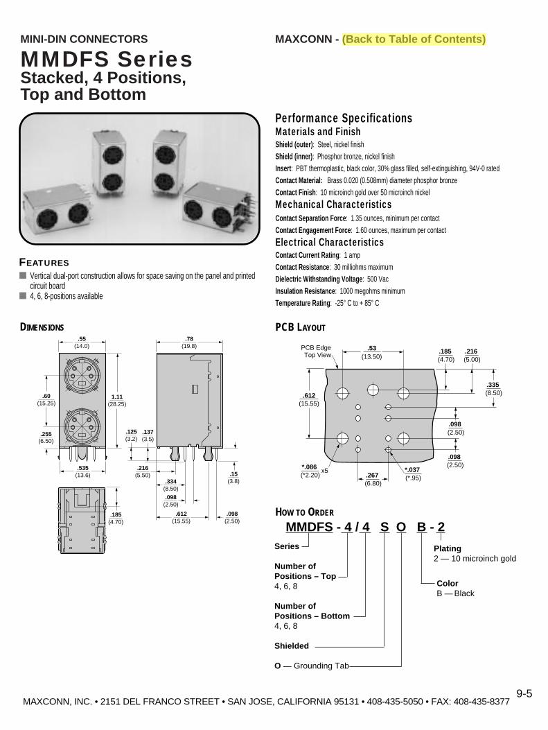
MAXCONN - (Back to Table of Contents)MINI-DIN CONNECTORS
MMDFS SeriesStacked, 4 Positions,Top and Bottom
Performance SpecificationsMaterials and FinishShield (outer) : Steel, nickel finishShield (inner) : Phosphor bronze, nickel finishInsert : PBT thermoplastic, black color, 30% glass filled, self-extinguishing, 94V-0 ratedContact Material: Brass 0.020 (0.508mm) diameter phosphor bronzeContact Finish : 10 microinch gold over 50 microinch nickel
Mechanical CharacteristicsContact Separation Force : 1.35 ounces, minimum per contactContact Engagement Force : 1.60 ounces, maximum per contact
Electrical CharacteristicsContact Current Rating : 1 ampContact Resistance : 30 milliohms maximumDielectric Withstanding Voltage : 500 VacInsulation Resistance : 1000 megohms minimumTemperature Rating : -25° C to + 85° C
FEATURES■ Vertical dual-port construction allows for space saving on the panel and printed
circuit board■ 4, 6, 8-positions available
.15(3.8)
.185(4.70)
.098(2.50)
.60(15.25)
.137(3.5)
.125(3.2)
.216(5.50)
.255(6.50)
1.11(28.25)
.55(14.0)
.78(19.8)
.334(8.50)
.098(2.50)
.612(15.55)
.535(13.6)
DIMENSIONS
.612(15.55)
(13.50)PCB EdgeTop View
(*2.20)x5*.086
(*.95)*.037
(6.80).267
(2.50).098
(2.50).098
(4.70).185
(5.00).216
(8.50).335
.53
PCB LAYOUT
HOW TO ORDER
MMDFS - 4 / 4 S O B - 2Series
Number ofPositions – Top4, 6, 8
Number ofPositions – Bottom4, 6, 8
Shielded
O — Grounding Tab
Plating2 — 10 microinch gold
ColorB — Black
MAXCONN, INC. • 2151 DEL FRANCO STREET • SAN JOSE, CALIFORNIA 95131 • 408-435-5050 • FAX: 408-435-8377 9-5

MAXCONN, INC. • 2151 DEL FRANCO STREET • SAN JOSE, CALIFORNIA 95131 • 408-435-5050 • FAX: 408-435-83779-6
MAXCONN - (Back to Table of Contents)MINI-DIN CONNECTORS
MMDFS SeriesStacked, 6 Positions,Top and Bottom
.15(3.8)
.185(4.70)
.098(2.50)
.60(15.25)
.137(3.5)
.125(3.2)
.216(5.50)
.255(6.50)
1.11(28.25)
.55(14.0)
.78(19.8)
.334(8.50)
.098(2.50)
.612(15.55)
.535(13.6)
DIMENSIONS
.612(15.55)
(2.60)
(13.50)PCB EdgeTop View
.102(*2.20)x5*.086
(*.95)*.037
(6.80).267
(2.50).098
(2.50).098
(4.70).185
(5.00).216
(8.50).335
.53
PCB LAYOUT
HOW TO ORDER
MMDFS - 6 / 6 S O B - 2Series
Number ofPositions – Top4, 6, 8
Number ofPositions – Bottom4, 6, 8
Shielded
O — Grounding Tab
Plating2 — 10 microinch gold
ColorB — Black
FEATURES■ Vertical dual-port construction allows for space saving on the panel and printed
circuit board■ 4, 6, 8-positions available
Performance SpecificationsMaterials and FinishShield (outer) : Steel, nickel finishShield (inner) : Phosphor bronze, nickel finishInsert : PBT thermoplastic, black color, 30% glass filled, self-extinguishing, 94V-0 ratedContact Material: Brass 0.020 (0.508mm) diameter phosphor bronzeContact Finish : 10 microinch gold over 50 microinch nickel
Mechanical CharacteristicsContact Separation Force : 1.35 ounces, minimum per contactContact Engagement Force : 1.60 ounces, maximum per contact
Electrical CharacteristicsContact Current Rating : 1 ampContact Resistance : 30 milliohms maximumDielectric Withstanding Voltage : 500 VacInsulation Resistance : 1000 megohms minimumTemperature Rating : -25° C to + 85° C

MAXCONN, INC. • 2151 DEL FRANCO STREET • SAN JOSE, CALIFORNIA 95131 • 408-435-5050 • FAX: 408-435-83779-7
MAXCONN - (Back to Table of Contents)MINI-DIN CONNECTORS
MMDFS SeriesStacked, 8 Positions,Top and Bottom
.15(3.8)
.185(4.70)
.098(2.50)
.60(15.25)
.137(3.5)
.125(3.2)
.216(5.50)
.255(6.50)
1.11(28.25)
.55(14.0)
.78(19.8)
.334(8.50)
.098(2.50)
.612(15.55)
.535(13.6)
DIMENSIONS
.612(15.55)
(2.60)
(13.50)PCB EdgeTop View
.102(*2.20)x5*.086
(*.95)*.037
(6.80).267
(2.50).098
(2.50).098
(4.70).185
(5.00).216
(8.50).335
.53
PCB LAYOUT
FEATURES■ Vertical dual-port construction allows for space saving on the panel and
printed circuit board■ 4, 6, 8-positions available
Performance SpecificationsMaterials and FinishShield (outer) : Steel, nickel finishShield (inner) : Phosphor bronze, nickel finishInsert : PBT thermoplastic, black color, 30% glass filled, self-extinguishing, 94V-0 ratedContact Material: Brass 0.020 (0.508mm) diameter phosphor bronzeContact Finish : 10 microinch gold over 50 microinch nickel
Mechanical CharacteristicsContact Separation Force : 1.35 ounces, minimum per contactContact Engagement Force : 1.60 ounces, maximum per contact
Electrical CharacteristicsContact Current Rating : 1 ampContact Resistance : 30 milliohms maximumDielectric Withstanding Voltage : 500 VacInsulation Resistance : 1000 megohms minimumTemperature Rating : -25° C to + 85° C
HOW TO ORDER
MMDFS - 8 / 8 S O B - 2Series
Number ofPositions – Top4, 6, 8
Number ofPositions – Bottom4, 6, 8
Shielded
O — Grounding Tab
Plating2 — 10 microinch gold
ColorB — Black

MAXCONN, INC. • 2151 DEL FRANCO STREET • SAN JOSE, CALIFORNIA 95131 • 408-435-5050 • FAX: 408-435-83779-8
MINI-DIN CONNECTORS
MMDV SeriesCircular ConnectorsVertical T ype, 3 to 8 Contacts
Arrangementof Contacts
5.6
1.6
0.41 EE 2
3
9.6
12
3
12
34
4.6
5.6
1.6
0.41 EE 2
3 4
9.4
1
23
45
Numberof Contacts
PCB Layout
12
34
56
4.6
1.35.6
1.61.9
0.4
2.7 2.4
12 EE
3 4
5 6
9.4
4.6
1.05.6
1.6 0.4
2.7
1 EE
2 3
4 5
9.4
f13.5
f148
1
3.5
0.8
9.5
1
DIMENSIONS— 3 TO 8 CONTACTS
4.6
1.01.3
5.6
1.61.9
0.4
2.7 2.4
12 EE
3 4
5 6 7
9.4
12
34
567
12
34
5
678
4.6
0.11.0
1.35.6
1.61.9
0.4
2.7 2.4
12 EE
3 4 5
6 7 8
9.4
Arrangementof Contacts
Numberof Contacts
PCB Layout
HOW TO ORDER
MMDV - 8
Series
Number ofPositions3, 4, 5, 6, 7, 8
3
4
5
6
8
7
Performance SpecificationsMaterials and FinishShield/Shield : Steel, nickel finishInsert : PBT thermoplastic, black color, 30% glass filled, self-extinguishing, 94V-0 ratedContact Material: Phosphor bronzeContact Finish : Plated silver 30 microinch over 50 microinch nickel
Mechanical CharacteristicsContact Separation Force : 0.9 Kg to 3 KgContact Engagement Force : 4.5 Kg maximum
Electrical CharacteristicsContact Current Rating : 100 Vac, 1 amp maximum or 12Vdc, 2 amp maximumContact Resistance : 30 milliohms maximumDielectric Withstanding Voltage : 250 Vac/1 minuteInsulation Resistance : 50 megohms minimum at 250 VdcTemperature Rating : -25° C to + 85° C
MAXCONN - (Back to Table of Contents)

f13
f158
1
4.09.513.5
1
MINI-DIN CONNECTORS
MMDV SeriesCircular ConnectorsVertical T ype, 9 Contacts
MAXCONN - (Back to Table of Contents)
DIMENSIONS— 9 CONTACTS
Performance SpecificationsMaterials and FinishShield/Shield : Steel, nickel finishInsert : PBT thermoplastic, black color, 30% glass filled, self-extinguishing, 94V-0 ratedContact Material: Phosphor bronzeContact Finish : Plated silver 30 microinch over 50 microinch nickel
Mechanical CharacteristicsContact Separation Force : 0.9 Kg to 3 KgContact Engagement Force : 4.5 Kg maximum
Electrical CharacteristicsContact Current Rating : 100 Vac, 1 amp maximum or 12Vdc, 2 amp maximumContact Resistance : 30 milliohms maximumDielectric Withstanding Voltage : 250 Vac/1 minuteInsulation Resistance : 50 megohms minimum at 250 VdcTemperature Rating : -25° C to + 85° C
Arrangementof Contacts
Numberof Contacts
PCB Layout
123456
9 8 7
3.23.2
1.80.40.6
2.3
2.5
0.6
2.7 2.7
1.01.0
5.2 5.2
1 2
3 4 5 6
7 8 99
MAXCONN, INC. • 2151 DEL FRANCO STREET • SAN JOSE, CALIFORNIA 95131 • 408-435-5050 • FAX: 408-435-83779-9
PART NUMBER: MMDV-9

MAXCONN, INC. • 2151 DEL FRANCO STREET • SAN JOSE, CALIFORNIA 95131 • 408-435-5050 • FAX: 408-435-83779-10
MAXCONN - (Back to Table of Contents)MINI-DIN CONNECTORS
MMDM SeriesShielded Male Plug
f9.00
f13.40
6.0036.16
51.16
f5.10
f8.20
Polarizing KeyContact
Shield
Boot andStrain Relief
DIMENSIONS
HOW TO ORDER
3 4
21
3
21
3
54
21
3
5 76
4
21
3 5
7 86
4
21
3
5 6
4
21
Arrangementof Contacts
Numberof Contacts
Arrangementof Contacts
Numberof Contacts
3
4
5
6
7
8
MMDM - 8 - S - B - 1
Series
Number ofPositions3, 4, 5, 6, 7, 8
S — Shielded
Plating1 — 50 microinch Silver2 — 10 microinch Gold
Performance SpecificationsMaterials and FinishShield/Shield : Steel, nickel finishInsert : PBT thermoplastic, black color, 30% glass filled, self-extinguishing, 94V-0 ratedContact Material: BrassContact Finish : Plated silver 30 microinch over 50 microinch nickel
Mechanical CharacteristicsContact Separation Force : 1.35 ounces, minimum per contactContact Engagement Force : 1.60 ounces, maximum per contact
Electrical CharacteristicsContact Current Rating : 1 ampContact Resistance : 30 milliohms maximumDielectric Withstanding Voltage : 500 VacInsulation Resistance : 1000 megohms minimumTemperature Rating : -25° C to + 85° C
FEATURES■ Male — Shielded■ Polarizing key
* 5,000 piece minimum order
ColorB — Black (Standard)A — Platinum* (Apple Computer)I — Pearl white* (IBM)
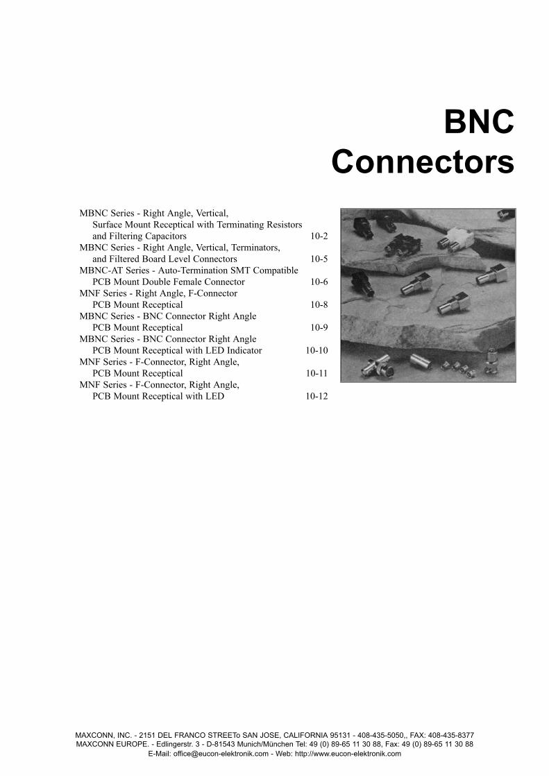
MBNC Series - Right Angle, Vertical, Surface Mount Receptical with Terminating Resistors and Filtering Capacitors 10-2
MBNC Series - Right Angle, Vertical, Terminators, and Filtered Board Level Connectors 10-5
MBNC-AT Series - Auto-Termination SMT Compatible PCB Mount Double Female Connector 10-6
MNF Series - Right Angle, F-Connector PCB Mount Receptical 10-8
MBNC Series - BNC Connector Right Angle PCB Mount Receptical 10-9
MBNC Series - BNC Connector Right Angle PCB Mount Receptical with LED Indicator 10-10
MNF Series - F-Connector, Right Angle, PCB Mount Receptical 10-11
MNF Series - F-Connector, Right Angle, PCB Mount Receptical with LED 10-12
MAXCONN, INC. - 2151 DEL FRANCO STREETo SAN JOSE, CALIFORNIA 95131 - 408-435-5050,, FAX: 408-435-8377MAXCONN EUROPE. - Edlingerstr. 3 - D-81543 Munich/München Tel: 49 (0) 89-65 11 30 88, Fax: 49 (0) 89-65 11 30 88
E-Mail: [email protected] - Web: http://www.eucon-elektronik.com
BNCConnectors

MBNC SeriesRight Angle, V ertical, SurfaceMount Receptical with T erminatingResistors and Filtering Capacitors
Performance SpecificationsMaterials and FinishMetal Housing: 100 microinch minimum nickel plating over zinc alloy Contact : Contact area 1--–200 microinch tin/lead plating over
50 microinch nickel plating overallPlastic Insulator : PBT UL94V-0 rated black or whiteContact Insulator : PolypropyleneMounting Post : Tin plating over brassGrounding Terminal : Tin plating over copper wire
Electrical CharacteristicsImpedance : 75 ohmFrequency Range: 50 ohms 0–1 GHz
75 ohms 0–4 GHzOperating Voltage : 500 Volts RMSContact Resistance : 3.0 mohms maximum (gold)Dielectric Withstanding Voltage : 1500 Volts RMSInsulation Resistance : 5000 Megohms minimum
Mechanical CharacteristicsDurability : 500 cycles/mated/unmatedCeramic Capacitor : 4700PF @ 10% x 2 (9400PF)Resistive Value : 1/2 Watt 5% 50, 75, and 93 ohmsOperating Temperature : -40° C to + 85° C
Environmental CharacteristicsTemperature Range : -50°C to +85°CThermal Shock-Mill-Std : 1344, Method 1033, Condition ASalt Spray-Mill-Std : 1344, Methond 1001, Condition BPhysical Shock-Mill-Std : 1344, Method 2004, Condition GHumidity-Mill-Std : 1344, Method 1002, Procedure B Type 2
MAXCONN - (Back to Table of Contents)
MAXCONN, INC. • 2151 DEL FRANCO STREET • SAN JOSE, CALIFORNIA 95131 • 408-435-5050 • FAX: 408-435-837710-2
BNC CONNECTORS
FEATURES■ UL and CSA approved E107337 and E145613■ 50 and 75 ohm impedance■ 9400pF filtered option■ Terminating resistors
HOW TO ORDER
MBNC – – –
SeriesMBNC – SingleMSBNC – Stacked
FilteredBlank – Non-FilteredF – Filtered
R – Right AngleV – Vertical
InsulatorB – BlackW – WhiteM – All metal
PCB MountingBlank – Through holeS – SMT
Plating1 – Tin plated2 – Gold plated (Standard)
OptionsBlank – 50 ohms75 – 75 ohms

BNC CONNECTORS MAXCONN - (Back to Table of Contents)
MAXCONN, INC. • 2151 DEL FRANCO STREET • SAN JOSE, CALIFORNIA 95131 • 408-435-5050 • FAX: 408-435-837710-3
0.400 ± .0060.20 ± .006(5.08 ± 0.15) (10.16 ± 0.15)
0.10 ± .002(2.54 ± 0.05)
0.20 ± .006(5.08 ± 0.15)
0.79 ± .006(2.01 ± 0.05)
f
0.35 ± .006(0.89 ± 0.05)
f
PCB LAYOUT
MBNC-RW-150 ohm, Right Angle, Low Profile.516 Height, Thru Hole (White body) (Black optional)
DIMENSIONS
0.470(11.95)
0.505(12.83)
0.566 ± .009(14.40 ± 0.25) 1.386 ± .014
(35.20 ± 0.38)1/2 x 28 Unef
0.309 ± .014(7.87 ± 0.38)
0.340 ± .014(8.60 ± 0.38)
0.815 ± .014(20.70 ± 0.38)
0.516 ± .009(13.10 ± 0.25)0.272 ± .009
(6.90 ± 0.25)
0.112 ± .005(2.85 ± 0.13)
0.157 ± .009(4.00 ± 0.25)
Panel Cutout
0.4000.200(5.08)
(10.16)
0.100(2.54)
0.200(5.08)
0.79(2.01)
f
0.35(0.89)
f
PCB LAYOUT
MBNCF-RB-250 ohm, Right Angle, Filtered9400pf, .516 Height, Thru Hole (Black body standard)
DIMENSIONS
0.505(12.83 )
0.468(11.9)
Panel Cutout
4700PF ±10% 4700PF ±10%
SignalGround
(Spring Washer)
To Logic Ground
0.566(14.40)
1.386(35.20)
1/2 x 28 Unef
0.657(16.70)
0.516(13.10) 0.112
(2.85)
0.309(7.87)
0.340(8.60)
0.815(20.70)
0.272(6.90)
0.157(4.00)
MBNC-R-150 ohm, Right Angle, Low Profile.340 Height, Non-Insulated, Thru HoleDIMENSIONS
0.38(9.65)
f 0.38(9.85)
0.340(8.64)
0.44(11.20)
0.11(2.79)
0.340(8.64)
0.38(9.65)
0.860(21.84)
0.550(13.97)
0.70(17.78)
0.30(7.62)
0.94(2.4)
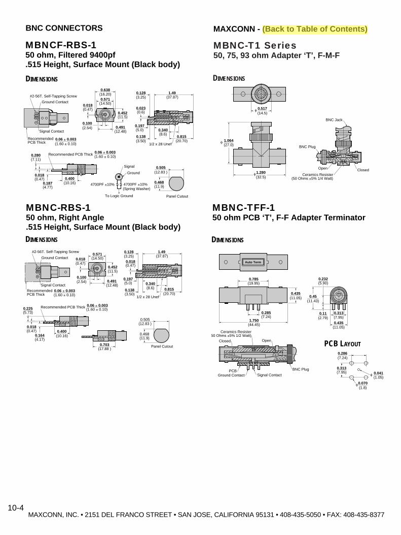
MBNC-T1 Series50, 75, 93 ohm Adapter ‘T’, F-M-F
DIMENSIONS
1.064(27.0)
f
f 0.517(14.5)
BNC Plug
BNC Jack
Open Closedf1.280
(32.5)���������Ceramics Resister(50 Ohms ±5% 1/4 Watt)
MBNC-TFF-150 ohm PCB ‘T’, F-F Adapter T erminator
DIMENSIONS
���������������0.435
(11.05)
0.313(7.95)
0.435(11.05)
BNC Plug
Signal ContactGround ContactPCB
Closed Open
Ceramics Resister50 Ohms ±5% 1/2 Watt)
0.232(5.90)
0.45(11.43)
0.11(2.79)
0.785
Auto Term
(19.95)
0.285(7.24)
1.750(44.45)
0.313(7.95)
0.286(7.24)
0.041(1.05)
f
0.070(1.8)
f
PCB LAYOUT
MAXCONN, INC. • 2151 DEL FRANCO STREET • SAN JOSE, CALIFORNIA 95131 • 408-435-5050 • FAX: 408-435-8377
MAXCONN - (Back to Table of Contents)BNC CONNECTORS
10-4
MBNCF-RBS-150 ohm, Filtered 9400pf.515 Height, Surface Mount (Black body)
DIMENSIONS
���������0.280(7.11)
0.018(0.47)
#2-56T. Self-Tapping Screw
Ground Contact
Signal Contact
RecommendedPCB Thick
0.187(4.77)
0.400(10.16) 4700PF ±10% 4700PF ±10%
0.505(12.83 )
Signal
Ground
(14.50)
0.468(11.9)
Panel Cutout
(Spring Washer)
To Logic Ground
0.06 ± 0.003(1.60 ± 0.10)
Recommended PCB Thick 0.06 ± 0.003(1.60 ± 0.10)
0.571(16.20)0.638
(37.87)1.49
(12.48)0.491
0.018(0.47)
0.100(2.54)
0.452(11.5)
0.023(0.6)
0.197(5.0) 0.340
(8.6)0.815
(20.70)1/2 x 28 Unef
0.138(3.50)
0.128(3.25)
MBNC-RBS-150 ohm, Right Angle.515 Height, Surface Mount (Black body)
DIMENSIONS
������������0.225(5.73)
0.018(0.47)
#2-56T. Self-Tapping Screw
Ground Contact
Signal Contact
RecommendedPCB Thick
0.164(4.17)
0.400(10.16)
0.703(17.88 )
0.505(12.83 )
(14.50)
0.468(11.9)
Panel Cutout
0.06 ± 0.003(1.60 ± 0.10)
Recommended PCB Thick 0.06 ± 0.003(1.60 ± 0.10)
0.571 (37.87)1.49
(12.48)0.491
0.018(0.47)
0.100(2.54)
0.452(11.5)
0.018(0.47)
0.197(5.0) 0.340
(8.6) 0.815(20.70)
1/2 x 28 Unef
0.138(3.50)
0.128(3.25)
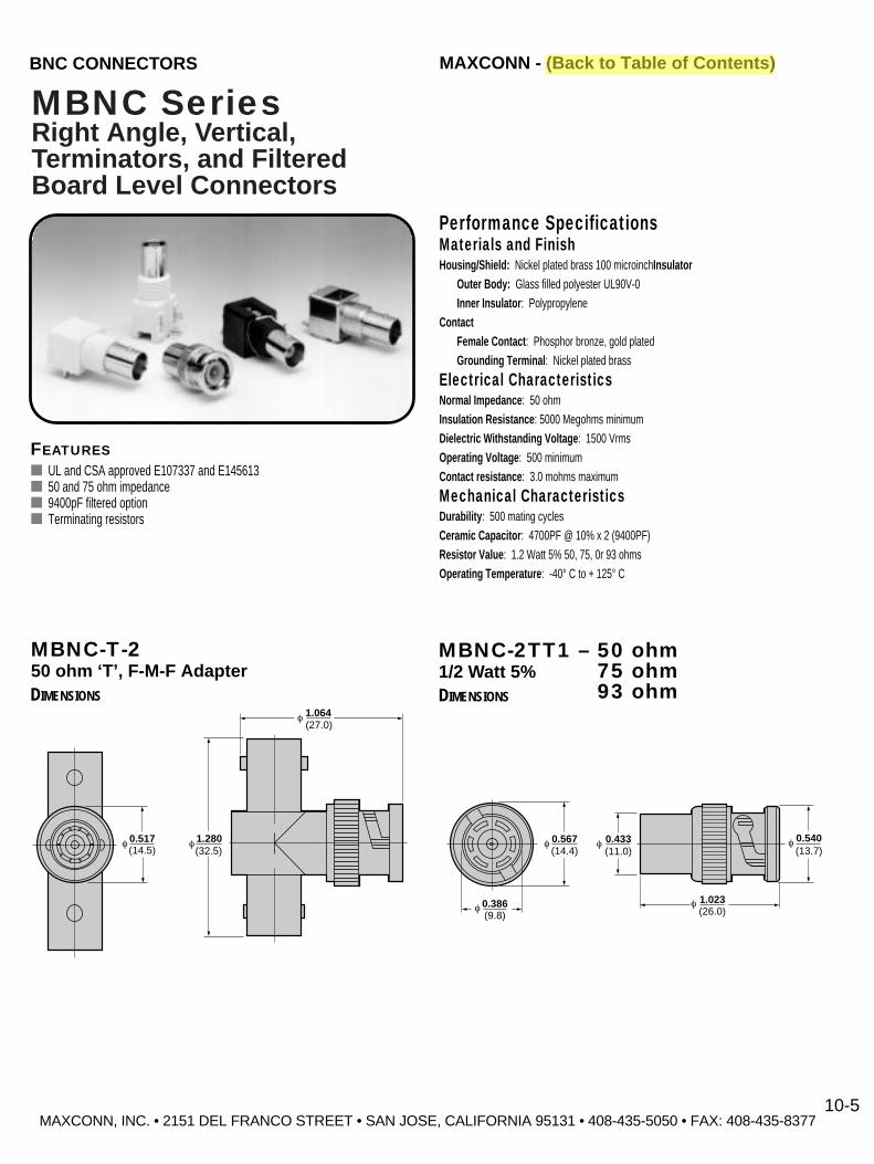
MBNC SeriesRight Angle, V ertical, Terminators, and Filtered Board Level Connectors
Performance SpecificationsMaterials and FinishHousing/Shield: Nickel plated brass 100 microinchInsulator
Outer Body: Glass filled polyester UL90V-0Inner Insulator : Polypropylene
ContactFemale Contact : Phosphor bronze, gold platedGrounding Terminal : Nickel plated brass
Electrical CharacteristicsNormal Impedance : 50 ohmInsulation Resistance : 5000 Megohms minimumDielectric Withstanding Voltage : 1500 VrmsOperating Voltage : 500 minimumContact resistance : 3.0 mohms maximum
Mechanical CharacteristicsDurability : 500 mating cyclesCeramic Capacitor : 4700PF @ 10% x 2 (9400PF)Resistor Value : 1.2 Watt 5% 50, 75, 0r 93 ohmsOperating Temperature : -40° C to + 125° C
MAXCONN - (Back to Table of Contents)
MAXCONN, INC. • 2151 DEL FRANCO STREET • SAN JOSE, CALIFORNIA 95131 • 408-435-5050 • FAX: 408-435-837710-5
BNC CONNECTORS
MBNC-2TT1 – 50 ohm1/2 Watt 5% 75 ohm
93 ohmDIMENSIONS
0.386(9.8)
f
0.567(14.4)
1.023(26.0)
f
f f 0.540(13.7)
f 0.433(11.0)
1.064(27.0)
f
f 0.517(14.5)
f 1.280(32.5)
MBNC-T-250 ohm ‘T’, F-M-F Adapter
DIMENSIONS
FEATURES■ UL and CSA approved E107337 and E145613■ 50 and 75 ohm impedance■ 9400pF filtered option■ Terminating resistors

MBNC-AT SeriesAuto-T ermination SMTCompatible PCB Mount Double Female Connector
Performance SpecificationsMaterials and FinishBody: 100µ inch minimum nickel plating over zinc alloyFemale Insulator: Polypropylene UL 94HBRetaintion Insulator: TeflonMale Contact: Gold plating over brassFemale Contact: Gold plating over high strength copperRetaintion Washer: Gold plating over copper wireThick Film Chip Resistors: 50 ohms ±1/4 Watt (max. over load voltage –400Vdc)Retaintion Washer: Nickel plating over copper stripRetaintion Cover: Nickel plating over Zinc alloy
Electrical CharacteristicsNormal Impedance : 50 ohmsFrequency Range : 0~1GHzOperating Voltage : 500 VrmsContact Resistance : 3.0 milliohms maximumDielectric Withstanding Voltage : 500 VrmsInsulation Resistance : 5000 Megohms minimumCeramic Resistor: Thick film chip resistors: 50 ohms ±5%, 1.4 Watt
Voltage RatingE=Ã PRE=Voltage Rating (V)P=Power Rating at 70°C (W)R=Standard Resitance Values (½)
Mechanical CharacteristicsMating/Unmating : 500 cycles
Envionmental CharacteristicsTemperature Rating : -55° C to + 85° CThermal Shock : MIL-STD-1344, Method 1003, Cond. ASalt Spray : MIL-STD-1344, Method 1001, Cond. BPhysical Shock : MIL-STD-1344, Method 2004, Cond. GHunidity : MIL-STD-1344, Method 1002, Cond. B (type 2)
MAXCONN - (Back to Table of Contents)
MAXCONN, INC. • 2151 DEL FRANCO STREET • SAN JOSE, CALIFORNIA 95131 • 408-435-5050 • FAX: 408-435-837710-6
BNC CONNECTORS
DIMENSIONS
0.441(11.2)
0.441(11.2)
1.280
Auto Term.
(32.5)
0.677(17.2)
0.224(5.7)
0.122(28.50)
0.079(2.0)
0.079(2.0)
f
f
0.079(2.0)0.087
(2.2)
0.067(1.7)
0.067(1.7)
0.067(1.7)
0.067(1.7)
0.063 ± 0.004(1.60 ± 0.10)
0.150(3.8)
0.098(2.5)
0.098(2.5)
0.472(12.0)
0.472(12.0)
0.244(6.2)
Typ.0.244(6.2)
0.150(3.8)
Typ.
PCB LAYOUT

����������������
PCB
BNC Plug
Open
Ceramic Resister(50W ±5% 1/4 Watt)
Close
USED VERTICALUSED HORIZONTAL
BNC CONNECTORS MAXCONN - (Back to Table of Contents)
MAXCONN, INC. • 2151 DEL FRANCO STREET • SAN JOSE, CALIFORNIA 95131 • 408-435-5050 • FAX: 408-435-837710-7
MBNC-AT SeriesAuto-T ermination, SMT -CompatiblePCB Mount Double Female Connector
���������������
0.063 ± 0.004PCB Thick
BNC Plug
Open
Ceramic Resister(50W ±5% 1/4 Watt)
Close
(1.60 ± 0.10)

MBNC SeriesBNC Connector Right Angle PCB Mount Receptical
MAXCONN - (Back to Table of Contents)
MAXCONN, INC. • 2151 DEL FRANCO STREET • SAN JOSE, CALIFORNIA 95131 • 408-435-5050 • FAX: 408-435-837710-8
BNC CONNECTORS
DIMENSIONS
0.522(13.26)
BoardLock
0.100(2.54)
A
C
0.286(7.25)
Center Contact/SignalOuter Contact/Ground
0.543(13.79)
1.094(27.78)
0.075 ± .005(1.905 ± 0.13)
Recommended Panel Thickness Max.
(Round Cutout Only)
0.102(2.59)
0.276(7.00)
0.100(2.54)
0.039(0.98)
0.219(5.56)
0.250(6.35) 0.050
(1.27)B
0.157(3.99)
0.276(7.00)
12
1
2
Ports A B C1 0.571 0.400 —
14.50 10.16 —2 1.272 1.10 0.701
32.31 27.97 17.814 2.67 2.50 0.701
68.89 63.53 17.81
FEATURES■ UL and CSA approved E107337 and E145613■ Low profile■ Space saving■ High frequency
Performance SpecificationsMaterials and FinishContact: Contact area 100–200 microinch tin/lead plating over 50 microinch
nickle plating overallGround Terminal: Tin plating over copper wireThreaded Body: 100 microinch minimum nickel plating over zinc alloyInsulator: Polypropylene UL 94HBHousing: PBT (UL 94V-O)Mounting Post: Tin plating over brass
Electrical CharacteristicsNormal Impedance : Non-constantFrequency Range : 0~2GHzOperating Voltage : 250 VrmsContact Resistance : 3.0 milliohms maximum (gold)Dielectric Withstanding Voltage : 1500 VrmsInsulation Resistance : 5000 Megohms minimum
Mechanical CharacteristicsDurability : 500 cycles/mated/unmatedContact Separation Force : 1.0 kg minimum (total connector)Contact Enganement Force : 1.27 kg maximum (total connector)
Envionmental CharacteristicsTemperature Rating : -55° C to + 85° CThermal Shock : MIL-STD-1344, Method 1003, Cond. ASalt Spray : MIL-STD-1344, Method 1001, Cond. BPhysical Shock : MIL-STD-1344, Method 2004, Cond. GHunidity : MIL-STD-1344, Method 1002, Cond. B (type 2)

MBNC SeriesBNC Connector Right Angle PCB Mount RecepticalWith LED Indicator
MAXCONN - (Back to Table of Contents)
MAXCONN, INC. • 2151 DEL FRANCO STREET • SAN JOSE, CALIFORNIA 95131 • 408-435-5050 • FAX: 408-435-837710-9
BNC CONNECTORS
DIMENSIONS
0.522(13.26)
LED1(Green Color)
BoardLock
LED2(Yellow Color)
0.100(2.54)
A
C
0.286(7.25)
0.543(13.79)
1.094(27.78)
0.075 ± .005(1.905 ± 0.13)
Recommended Panel Thickness Max.
(Round Cutout Only)
0.102(2.59)
0.276(7.00)
0.100(2.54)
0.039(0.98)
0.219(5.56)
0.250(6.35) 0.050
(1.27)B
0.157(3.99)
0.276(7.00)
+ –+ –+ –+ –+ –+ –+ –+ –
12 3
3
Center Contact/SignalCenter Contact/SignalLED Contact x16
1
2
FEATURES■ UL and CSA approved E107337 and E145613■ Low profile■ Space saving■ High frequency■ Optional LED
Performance SpecificationsMaterials and FinishContact: Contact area 100–200 microinch tin/lead plating over 50 microinch
nickle plating overallGround Terminal: Tin plating over copper wireThreaded Body: 100 microinch minimum nickel plating over zinc alloyInsulator: Polypropylene UL 94HBHousing: PBT (UL 94V-O)Mounting Post: Tin plating over brass
Electrical CharacteristicsNormal Impedance : Non-constantFrequency Range : 0~2GHzOperating Voltage : 250 VrmsContact Resistance : 3.0 milliohms maximum (gold)Dielectric Withstanding Voltage : 1500 VrmsInsulation Resistance : 5000 Megohms minimum
Mechanical CharacteristicsDurability : 500 cycles/mated/unmatedContact Separation Force : 1.0 kg minimum (total connector)Contact Enganement Force : 1.27 kg maximum (total connector)
Envionmental CharacteristicsTemperature Rating : -55° C to + 85° CThermal Shock : MIL-STD-1344, Method 1003, Cond. ASalt Spray : MIL-STD-1344, Method 1001, Cond. BPhysical Shock : MIL-STD-1344, Method 2004, Cond. GHunidity : MIL-STD-1344, Method 1002, Cond. B (type 2)
Optional LED CharacteristicsLED: Yellow LED: GaASP/GaP
Green LED: GaPLuninous Intensity(mcd) :
The maximum for 10mA is 1.25 VsThe minimum for 10mA is 0.5 Vs
Wavelength (nm) :LED1 green: 565 nmLED2 yellow: 590 nm
Viewing Angle : 2q1/2: 110°
Ports A B C1 0.571 0.400 —
14.50 10.16 —2 1.272 1.10 0.701
32.31 27.97 17.814 2.67 2.50 0.701
68.89 63.53 17.81

MNF SeriesRight Angle, F-ConnectorPCB Mount Receptical
MAXCONN - (Back to Table of Contents)
MAXCONN, INC. • 2151 DEL FRANCO STREET • SAN JOSE, CALIFORNIA 95131 • 408-435-5050 • FAX: 408-435-837710-10
BNC CONNECTORS
FEATURES■ UL and CSA approved E107337 and E145613■ 50 and 75 ohm impedance■ 9400pF filtered option■ Terminating resistors
HOW TO ORDER
MNF – – –
SeriesMBNC – BNCMNF – F-type
ShieldingBlank – Withour shieldS – Shielded
GangedS – SingleG – Ganged
MountingR – Right angleV – Vertical
Number of Ports1, 2, 4
OptionsBlank – Without LEDL1 – LED green/yellow (Standard)L2 – LED yellow/greenBlank – Without combinationC – Combination (F and BNC, RJ-11, RJ45)
Contact Plating1 – Tin plated over nickel2 – Gold plated over nickel (Standard)
Performance SpecificationsMaterials and FinishContact: Contact area 100–200 microinch tin/lead plating over 50 microinch
nickle plating overallGround Terminal: Tin plating over copper wireThreaded Body: 100 microinch minimum nickel plating over zinc alloyInsulator: Polypropylene UL 94HBHousing: PBT (UL 94V-O)Mounting Post: Tin plating over brass
Electrical CharacteristicsNormal Impedance : Non-constantFrequency Range : 0~2GHzOperating Voltage : 250 VrmsContact Resistance : 3.0 milliohms maximum (gold)Dielectric Withstanding Voltage : 1500 VrmsInsulation Resistance : 5000 Megohms minimum
Mechanical CharacteristicsDurability : 500 cycles/mated/unmatedContact Separation Force : 1.0 kg minimum (total connector)Contact Enganement Force : 1.27 kg maximum (total connector)
Envionmental CharacteristicsTemperature Rating : -55° C to + 85° CThermal Shock : MIL-STD-1344, Method 1003, Cond. ASalt Spray : MIL-STD-1344, Method 1001, Cond. BPhysical Shock : MIL-STD-1344, Method 2004, Cond. GHunidity : MIL-STD-1344, Method 1002, Cond. B (type 2)
Optional LED CharacteristicsLED: Yellow LED: GaASP/GaP
Green LED: GaPLuninous Intensity(mcd) :
The maximum for 10mA is 1.25 VsThe minimum for 10mA is 0.5 Vs
Wavelength (nm) :LED1 green: 565 nmLED2 yellow: 590 nm
Viewing Angle : 2q1/2: 110°

MNF SeriesF-Connector , Right Angle,PCB Mount Receptical
MAXCONN - (Back to Table of Contents)
MAXCONN, INC. • 2151 DEL FRANCO STREET • SAN JOSE, CALIFORNIA 95131 • 408-435-5050 • FAX: 408-435-837710-11
BNC CONNECTORS
DIMENSIONS
0.522(13.26)
BoardLock
0.100(2.54)
A
C
0.286(7.25)
0.543(13.79)
1.094(27.78)
0.075 ± .005(1.905 ± 0.13)
Recommended Panel Thickness Max.
(Round Cutout Only)
0.102(2.59)
0.100(2.54)
0.039(0.98)
0.219(5.56)
0.250(6.35) 0.050
(1.27)B
0.157(3.99)
0.276(7.00)
12
Center Contact/SignalCenter Contact/Signal
3/8 – 32UNEF x4
1
2
FEATURES■ UL and CSA approved E107337 and E145613■ Low profile■ Space saving■ High frequency■ Optional LED
Performance SpecificationsMaterials and FinishContact: Contact area 100–200 microinch tin/lead plating over 50 microinch
nickle plating overallGround Terminal: Tin plating over copper wireThreaded Body: 100 microinch minimum nickel plating over zinc alloyInsulator: Polypropylene UL 94HBHousing: PBT (UL 94V-O)Mounting Post: Tin plating over brass
Electrical CharacteristicsNormal Impedance : Non-constantFrequency Range : 0~2GHzOperating Voltage : 250 VrmsContact Resistance : 3.0 milliohms maximum (gold)Dielectric Withstanding Voltage : 1500 VrmsInsulation Resistance : 5000 Megohms minimum
Mechanical CharacteristicsDurability : 500 cycles/mated/unmatedContact Separation Force : 1.0 kg minimum (total connector)Contact Enganement Force : 1.27 kg maximum (total connector)
Envionmental CharacteristicsTemperature Rating : -55° C to + 85° CThermal Shock : MIL-STD-1344, Method 1003, Cond. ASalt Spray : MIL-STD-1344, Method 1001, Cond. BPhysical Shock : MIL-STD-1344, Method 2004, Cond. GHunidity : MIL-STD-1344, Method 1002, Cond. B (type 2)
Optional LED CharacteristicsLED: Yellow LED: GaASP/GaP
Green LED: GaPLuninous Intensity(mcd) :
The maximum for 10mA is 1.25 VsThe minimum for 10mA is 0.5 Vs
Wavelength (nm) :LED1 green: 565 nmLED2 yellow: 590 nm
Viewing Angle : 2q1/2: 110°
Ports A B C1 0.571 0.400 —
14.50 10.16 —2 1.272 1.10 0.701
32.31 27.97 17.814 2.67 2.50 0.701
68.89 63.53 17.81

MNF SeriesF-Connector , Right Angle,PCB Mount Recepticalwith LED
MAXCONN - (Back to Table of Contents)
MAXCONN, INC. • 2151 DEL FRANCO STREET • SAN JOSE, CALIFORNIA 95131 • 408-435-5050 • FAX: 408-435-837710-12
BNC CONNECTORS
DIMENSIONS
0.522(13.26)
LED1(Green Color)
BoardLock
LED2(Yellow Color)
0.100(2.54)
A
C
0.286(7.25)
0.543(13.79)
1.094(27.78)
0.075 ± .005(1.905 ± 0.13)
Recommended Panel Thickness Max.
(Round Cutout Only)
0.102(2.59)
0.100(2.54)
0.039(0.98)
0.219(5.56)
0.250(6.35) 0.050
(1.27)B
0.157(3.99)
0.276(7.00)
+ –+ –+ –+ –+ –+ –+ –+ –
12 3
3
Center Contact/SignalCenter Contact/SignalLED Contact x16
3/8 – 32UNEF x4
1
2
FEATURES■ UL and CSA approved E107337 and E145613■ Low profile■ Space saving■ High frequency■ Optional LED
Performance SpecificationsMaterials and FinishContact: Contact area 100–200 microinch tin/lead plating over 50 microinch
nickle plating overallGround Terminal: Tin plating over copper wireThreaded Body: 100 microinch minimum nickel plating over zinc alloyInsulator: Polypropylene UL 94HBHousing: PBT (UL 94V-O)Mounting Post: Tin plating over brass
Electrical CharacteristicsNormal Impedance : Non-constantFrequency Range : 0~2GHzOperating Voltage : 250 VrmsContact Resistance : 3.0 milliohms maximum (gold)Dielectric Withstanding Voltage : 1500 VrmsInsulation Resistance : 5000 Megohms minimum
Mechanical CharacteristicsDurability : 500 cycles/mated/unmatedContact Separation Force : 1.0 kg minimum (total connector)Contact Enganement Force : 1.27 kg maximum (total connector)
Envionmental CharacteristicsTemperature Rating : -55° C to + 85° CThermal Shock : MIL-STD-1344, Method 1003, Cond. ASalt Spray : MIL-STD-1344, Method 1001, Cond. BPhysical Shock : MIL-STD-1344, Method 2004, Cond. GHunidity : MIL-STD-1344, Method 1002, Cond. B (type 2)
Optional LED CharacteristicsLED: Yellow LED: GaASP/GaP
Green LED: GaPLuninous Intensity(mcd) :
The maximum for 10mA is 1.25 VsThe minimum for 10mA is 0.5 Vs
Wavelength (nm) :LED1 green: 565 nmLED2 yellow: 590 nm
Viewing Angle : 2q1/2: 110°
Ports A B C1 0.571 0.400 —
14.50 10.16 —2 1.272 1.10 0.701
32.31 27.97 17.814 2.67 2.50 0.701
68.89 63.53 17.81

MSC Series - Excepts ISO 7818 IC Card 11-2
MAXCONN, INC. - 2151 DEL FRANCO STREETo SAN JOSE, CALIFORNIA 95131 - 408-435-5050,, FAX: 408-435-8377MAXCONN EUROPE. - Edlingerstr. 3 - D-81543 Munich/München Tel: 49 (0) 89-65 11 30 88, Fax: 49 (0) 89-65 11 30 88
E-Mail: [email protected] - Web: http://www.eucon-elektronik.com
Smart CardConnector

MSC SeriesExcepts ISO 7818 IC Card
Performance SpecificationsMaterials and FinishInsert: PBT thermoplastic, black color, 30% glass filled, self-extinguishing, 94V-0 ratedContact Material: Phosphor bronzeContact Finish : 30 microinch gold over nickel
Mechanical CharacteristicsCard Separation Force : 102 grams minimumCard Engagement Force : 511 grams maximum
Electrical CharacteristicsTemperature Rating: –40° C to + 100°C
DIMENSIONS
MSC-8 (8 contacts)
.157(4.00)
.118(3.00)
1.57(40.00)
1.57(40.00)
Through Hole Mounting
.039(1.00)
ConnectorBoundry
.368(9.35)
.129(3.28)
.870(22.10)
1.17(29.72)
2.28(58.00)
2.44(62.00)
.393(10.00)
.787(20.00)
1.50(38.10)
.118(3.00)
.150(3.28)
2X f f
f
.126(3.20)
4X f
1.25(31.74)
2.44(62.00)
Test Hole
Card Insertion Direction
Card Insertion Direction
5
3
1
12
14
6
8
10
16
18
MAXCONN, INC. • 2151 DEL FRANCO STREET • SAN JOSE, CALIFORNIA 95131 • 408-435-5050 • FAX: 408-435-8377
MAXCONN - (Back to Table of Contents)SMART CARD CONNECTOR
11-2
PCB LAYOUT

MSC SeriesExcepts ISO 7818 IC Card
MAXCONN, INC. • 2151 DEL FRANCO STREET • SAN JOSE, CALIFORNIA 95131 • 408-435-5050 • FAX: 408-435-8377
MAXCONN - (Back to Table of Contents)
11-3
SMART CARD CONNECTOR
�����.792
(20.12)
Card Insertion Direction
2.135(54.25)
2.283(58.00)
6
1015
18
5
111
14
.157(4.00)
.027(0.70)
Card
ContactConfiguration
(C5, 6)
ContactConfiguration(All Others)
0.10(2.54)
.283(7.20)
.303(7.70)
1.39(35.30)
.463(11.77)
.035(0.90)
.787(20.00)
.393(10.00)
DIMENSIONS
MSC-16 (16 contacts)
CARD INSERTION SPECIFICATIONCard Insertion End to Contact Center: 11.7mmContact Point Species: 7.7mmCard Insertion Depth: 35.5mmCard Thickness: 1.0mm Maximum

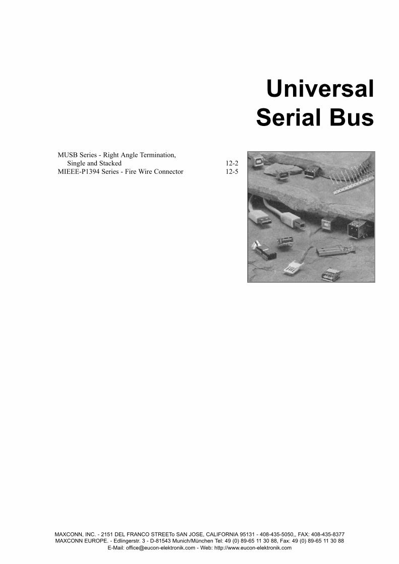
MUSB Series - Right Angle Termination, Single and Stacked 12-2
MIEEE-P1394 Series - Fire Wire Connector 12-5
MAXCONN, INC. - 2151 DEL FRANCO STREETo SAN JOSE, CALIFORNIA 95131 - 408-435-5050,, FAX: 408-435-8377MAXCONN EUROPE. - Edlingerstr. 3 - D-81543 Munich/München Tel: 49 (0) 89-65 11 30 88, Fax: 49 (0) 89-65 11 30 88
E-Mail: [email protected] - Web: http://www.eucon-elektronik.com
UniversalSerial Bus

MUSB SERIESRight Angle T ermination,Single and Stacked
FEATURES■ Plug and play technology■ Hot pluggable■ Single 4, 8-position connectors■ Consolidates serial ports and parallel ports, keyboard ports, mouse ports, and
game ports■ Compatible with asynchronous and isochronous data transfer methods■ Compatible with Windows ‘95 operating system■ Standard feature in new PC chipsets■ Eliminates the need for terminators■ UL and CSA approved E107337 and E145613
Performance SpecificationsMaterials and FinishShell: Tin plated, copper alloyInsert: PBT type D202G30, self-extuishing, 94V-0 rated, black colorContact Material: Phospher bronzeContact Finish: Palladium nickel
Electrical CharacteristicsContact Current Rating: 1 Amp 100Vac, 2 Amp 12VdcContact Resistance : 30 milliohms maximumDielectric Withstanding Voltage : 750 Vac for one minuiteInsulation Resistance : 1000 megohms minimum
Mechanical CharacteristicsTemperature Rating : -40° C to + 245° C
MAXCONN - (Back to Table of Contents)
MAXCONN, INC. • 2151 DEL FRANCO STREET • SAN JOSE, CALIFORNIA 95131 • 408-435-5050 • FAX: 408-435-837712-2
UNIVERSAL SERIAL BUSS
DIMENSIONS – SINGLE TYPE A
���
.20(5.12)
.55(14.00)
.404(10.28)
.492(12.50)
.517(13.13)
.226(5.75)
.111(2.84)
.146(3.72)
.28(7.12)
MUSB-4R-P
.107(2.71).404
(10.28)
.517(13.14)
Edge of Connector
.098(2.50)
.090 ± .003(2.30 ± .08)
x2
x8
f
.036 ± .003(0.92 ± .08)
f.079(2.00)
PCB LAYOUT (TOP VIEW)
HOW TO ORDER
MUSB – 4X – X – X – HT
Series
Number ofContacts4, *8
Termination TypeR—Right angleV—VerticalS—SMT
TypeBlank—Standard USB Type AB — USB Type B
PlatingP—Palladium nickel
High-Temperature
*8P right angle only

MAXCONN - (Back to Table of Contents)
MAXCONN, INC. • 2151 DEL FRANCO STREET • SAN JOSE, CALIFORNIA 95131 • 408-435-5050 • FAX: 408-435-837712-3
MUSB-4R-SRight Angle T ermination, Single, Surface Mount
UNIVERSAL SERIAL BUSS
MUSB-4VVertical T ermination, Single V ertical PCB Mount
DIMENSIONS – SINGLE TYPE A
DIMENSIONS – VERTICAL TYPE A
0.517(13.13)
0.7395(18.78)
0.523(13.30)
0.492
1 2 3 4
(12.50)
0.293(7.44)
0.225(5.71) 0.286
(7.26)
0.200(5.12)
0.555(14.09)
0.120(3.05)
0.617(15.67)
0.098
1 2 3 4
(2.5)0.079(2.0)
0.276(7.0)
0.178(4.52)
0.492(12.5)
0.516(13.1)
0.555(4.10)
0.277(7.0)
0.145(3.7)
0.405(10.3)
0.586(4.88)
0.579(14.7)
0.226(5.75)
0.291(7.40)
0.113(2.87)
0.141(3.58) 1 2 3 4
0.092(2.34)
Dia. 0.517(13.14)
0.044(1.12)
0.080(2.03)
0.276(7.01)
0.098(2.49)
0.517(13.14)
0.107(2.71)
0.098(2.50)
0.090 ± .003(2.3 ± 0.08)
x2 Dia.
0.036 ± .003(0.92 ± 0.08)
x4 Dia.
0.079(2.0)
PCB LAYOUT (TOP VIEW)
PCB LAYOUT (TOP VIEW)

MAXCONN - (Back to Table of Contents)
MAXCONN, INC. • 2151 DEL FRANCO STREET • SAN JOSE, CALIFORNIA 95131 • 408-435-5050 • FAX: 408-435-837712-4
.224(5.68)
.107(2.71)
.210(5.33)
.404(10.28)
.517(13.14)
Edge of Connector
.098(2.50)
.090 ± .003(2.30 ± .08)
x4 x8f.036 ± .003(0.92 ± .08)
f.079(2.00)
PCB LAYOUT (TOP VIEW)
MUSB-8R-PRight Angle T ermination, Single,Stacked PCB Mount
DIMENSIONS – STACKED TYPE A�������
.492(12.50)
.921(23.40)
.165(4.19)
.63(16.00)
.492(12.50)
.16(4.06)
.16(4.06)
.196(4.98)
.243(6.18)
.213(5.42)
.252(6.42)
.586(14.89)
.515(13.10)
.578(14.70)
.755(19.20)
UNIVERSAL SERIAL BUSS
MUSB-4R-BRight Angle T ermination, T ype ASingle PCBMountDIMENSIONS – SINGLE TYPE B PCB LAYOUT (TOP VIEW)
0.476(12.10)
0.630(16.01)
0.404(10.26)
0.333(8.45)
0.098(2.50)
0.151(3.84)
0.136(3.47)
0.435(11.05)
0.305(7.73)
0.079(2.00)
0.107(2.71)
0.098(2.50)
0.185(4.71)
0.188(4.77)
0.474(12.04)
12
3 4
0.036(0.91)Dia.
0.091(2.30)Dia.

MIEEE-P1394 SERIESFire Wire Connector
FEATURES■ Compliance with TA1394, IEEE, and JEDEC standards■ UL and CSA approved■ Hot pluggable■ Fast data 100 Mbps – 1Gbps■ Through hole or surface mount■ UL and CSA approved E107337 and E145613
Performance SpecificationsMaterials and FinishShell: Phospher bronze 100 microinch, tin plated over 40 microinch minimum nickelHousing: PBT UL 94V-0 type D202G30, black colorContact Material: Brass, selective gold flash over paladium nickel with tin leadsContact Finish: 1.05 microinch minimum,gold flash over 0.75 microinch minimum palladiumin mating area over 1.25 microinch minimum nickel
Electrical CharacteristicsContact Current Rating: 1 Amp 100Vac, 2 Amp 12VdcContact Resistance : 30 milliohms maximumDielectric Withstanding Voltage : 750 Vac for one minuiteInsulation Resistance : 1000 megohms minimum
Mechanical CharacteristicsTemperature Rating : -40° C to + 245° C ± 5° C
MAXCONN - (Back to Table of Contents)UNIVERSAL SERIAL BUSS
DIMENSIONS – SINGLE, SIDE RIGHT ANGLE
0.283(7.20)
0.246(6.25) 0.246
(6.25)
0.440(11.2)
0.240(6.10)
135
246
0.535(13.60)
0.338(8.60)
0.319(8.10)
0.484(12.30)
0.126(3.20)
0.059(1.50)
0.059(1.50)
0.118(3.00)
0.079(2.00)
0.079(2.00)
Pos. 2
Pos. 1
0.258(6.55)
0.079(2.00)
0.071(1.80)
0.079(2.00)
0.055(1.40) Dia.
Dia.0.032(0.80)
0.079(2.00)
0.071(1.79)
0.283(7.20)
0.142(3.60)
0.059(1.50)
0.059(1.50)
0.039(1.00)
0.079(2.00)
0.110(2.80)
0.039(1.00)
0.134(3.40)
0.079(2.00)
0.079(2.00)
0.079(2.00)
PCB LAYOUT (TOP VIEW)
HOW TO ORDER
MIEEE – P1394 – 6 – XX X – P
Series
Number ofContacts6—Single12—Dual row (side by side)
Termination Typ eBlank—Through holeSR—Side right angleR—Right angleV—VerticalPCB TerminationBlank—Through-holeS—Surface mount
PlatingP—Palladium
nickel
MAXCONN, INC. • 2151 DEL FRANCO STREET • SAN JOSE, CALIFORNIA 95131 • 408-435-5050 • FAX: 408-435-837712-5

MAXCONN - (Back to Table of Contents)
16-1MAXCONN, INC. • 2151 DEL FRANCO STREET • SAN JOSE, CALIFORNIA 95131 • 408-435-5050 • FAX: 408-435-8377
Sketch AP1 P2❏ Mini-DIN ❏ Mini-DIN❏ DIN ❏ DINGender Gender❏ Male ❏ Male❏ Female ❏ FemalePin Out (P1) Pin Out (P2)Shield Pin # Pin # 1 Pin # Pin # 2 Pin # Pin # 3 Pin # Pin # 4 Pin # Pin # 5 Pin # Pin # 6 Pin # Pin # 7 Pin # Pin # 8 Pin # Pin # 9 Pin #
P1
P1 P2
P2Sketch A
Sketch B
Sketch C
Length
Length
Make your own sketch and use list belowfor connector and cable type requirements.
Sketch BConnector TypeP1 Positions M/F P2 M/F❏ D-Subminiature ❏
❏ SCSI I ❏
❏ SCSI II ❏
❏ Centronics/Ribbon ❏
❏ 13W3 Coax Combo ❏
❏ Hi-Density D-Subminiature ❏
❏ Other Type Other Type Thumb Screws: Pin Out (P1) Pin Out (P2)❏ Metal *NOTE: Please provide pin-out specification for skecth B & C.❏ Molded❏ None
Cable Specifications❏ Straight ❏ Coiled LengthUL Approved (Y/N) AWG Number Conductors Paired (Y/N) Shielded: ❏ Braid ❏ FoilColor: Comments:
CUSTOM CABLES
MCBL Series


![[XLS] · Web view3.5000000000000003E-2 0.05 2.5000000000000001E-2 3.5000000000000003E-2 0.05 2.5000000000000001E-2 4.4999999999999998E-2 0.05 2.5000000000000001E-2 0.04 0.05 2.5000000000000001E-2](https://img.pdfslide.us/doc/110x75/5c8e2bb809d3f216698ba826/xls-web-view35000000000000003e-2-005-25000000000000001e-2-35000000000000003e-2.jpg)