Embed Size (px)
Citation preview
Connections

SERIAL DATA
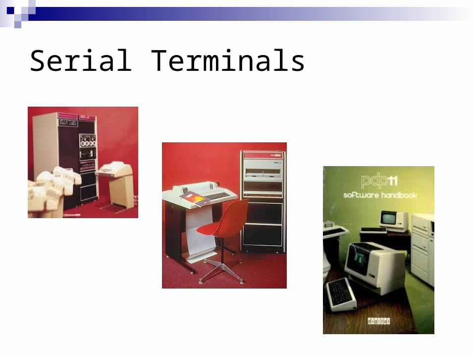
Serial Terminals
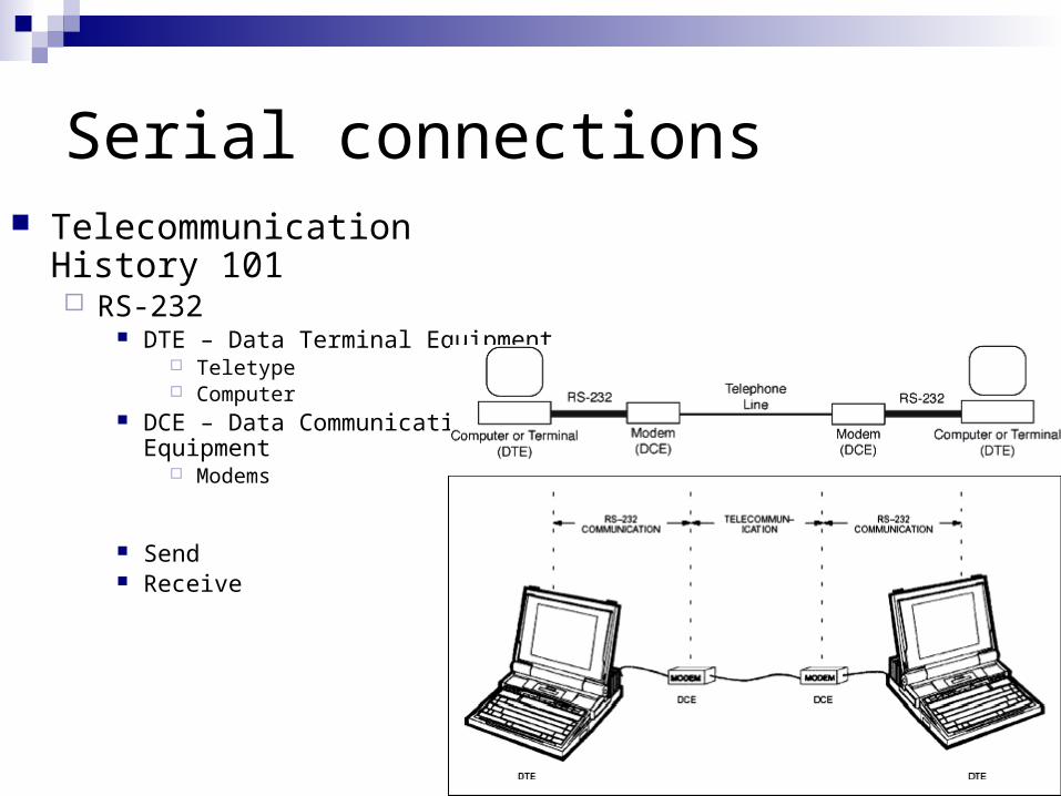
Serial connections Telecommunication History 101
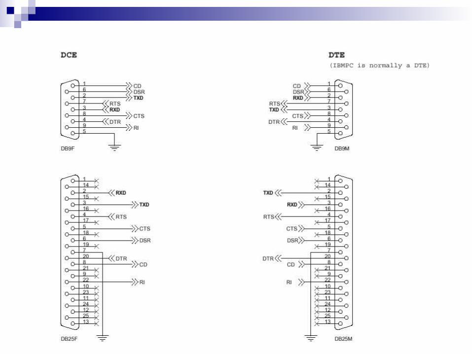
RS-232 DTE – Data Terminal Equipment
Teletype Computer
DCE – Data Communications Equipment
Modems
Send Receive
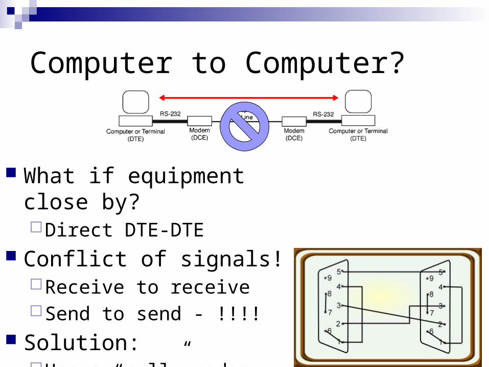
Computer to Computer?
What if equipment close by?Direct DTE-DTE
Conflict of signals!Receive to receiveSend to send - !!!!
Solution:Use a “null” modem
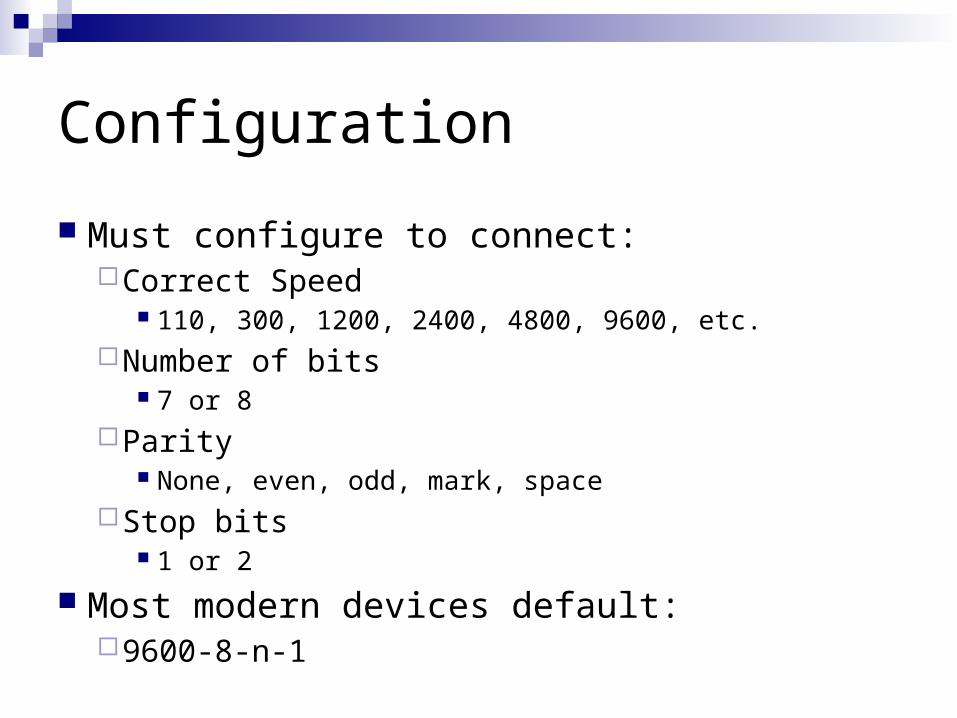
Configuration
Must configure to connect: Correct Speed
110, 300, 1200, 2400, 4800, 9600, etc. Number of bits
7 or 8 Parity
None, even, odd, mark, space Stop bits
1 or 2
Most modern devices default: 9600-8-n-1

ETHERNET
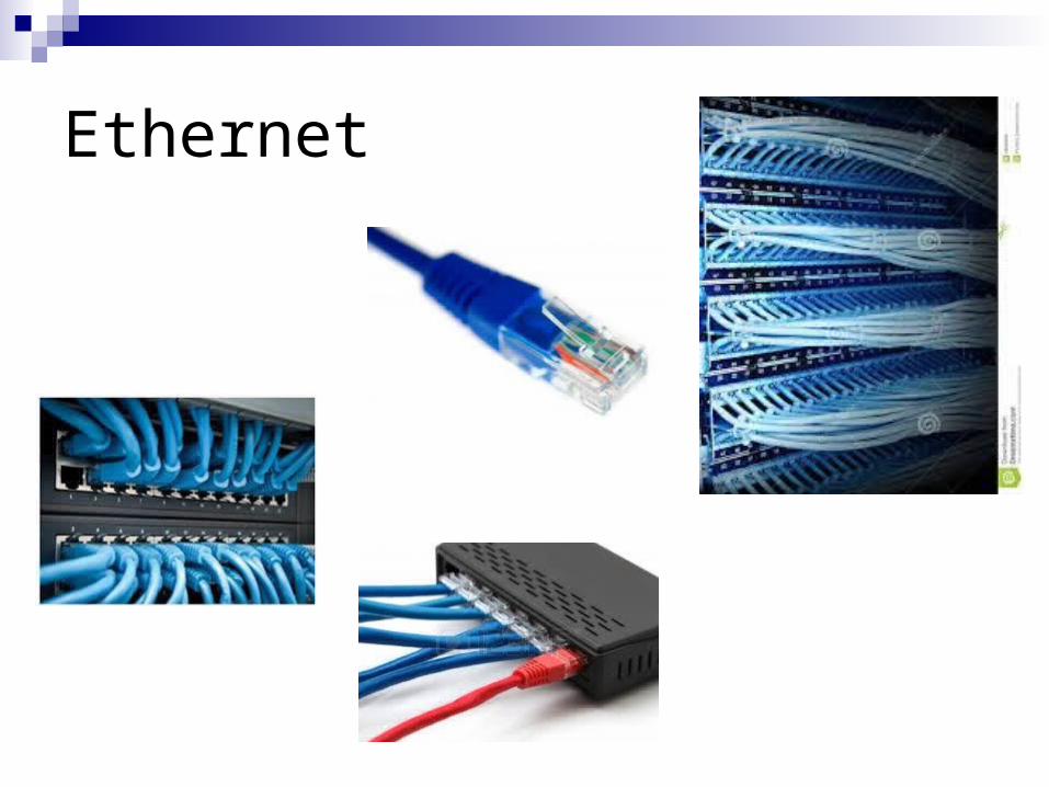
Ethernet
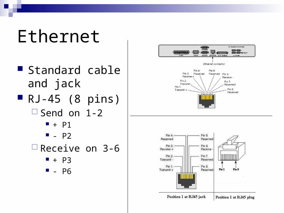
Ethernet
Standard cable and jack
RJ-45 (8 pins) Send on 1-2
+ P1 - P2
Receive on 3-6 + P3 - P6
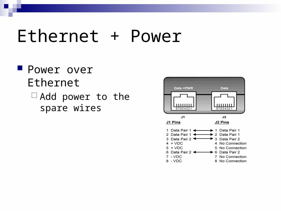
Ethernet + Power
Power over Ethernet Add power to the
spare wires
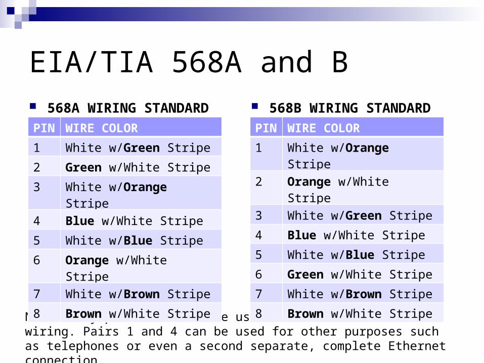
EIA/TIA 568A and B 568A WIRING STANDARD 568B WIRING STANDARD
Note: Only pairs 2 and 3 are used for Standard Ethernet wiring. Pairs 1 and 4 can be used for other purposes such as telephones or even a second separate, complete Ethernet connection.
PIN WIRE COLOR
1 White w/Green Stripe
2 Green w/White Stripe
3 White w/Orange Stripe
4 Blue w/White Stripe
5 White w/Blue Stripe
6 Orange w/White Stripe
7 White w/Brown Stripe
8 Brown w/White Stripe
PIN WIRE COLOR
1 White w/Orange Stripe
2 Orange w/White Stripe
3 White w/Green Stripe
4 Blue w/White Stripe
5 White w/Blue Stripe
6 Green w/White Stripe
7 White w/Brown Stripe
8 Brown w/White Stripe
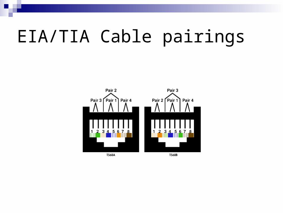
EIA/TIA Cable pairings
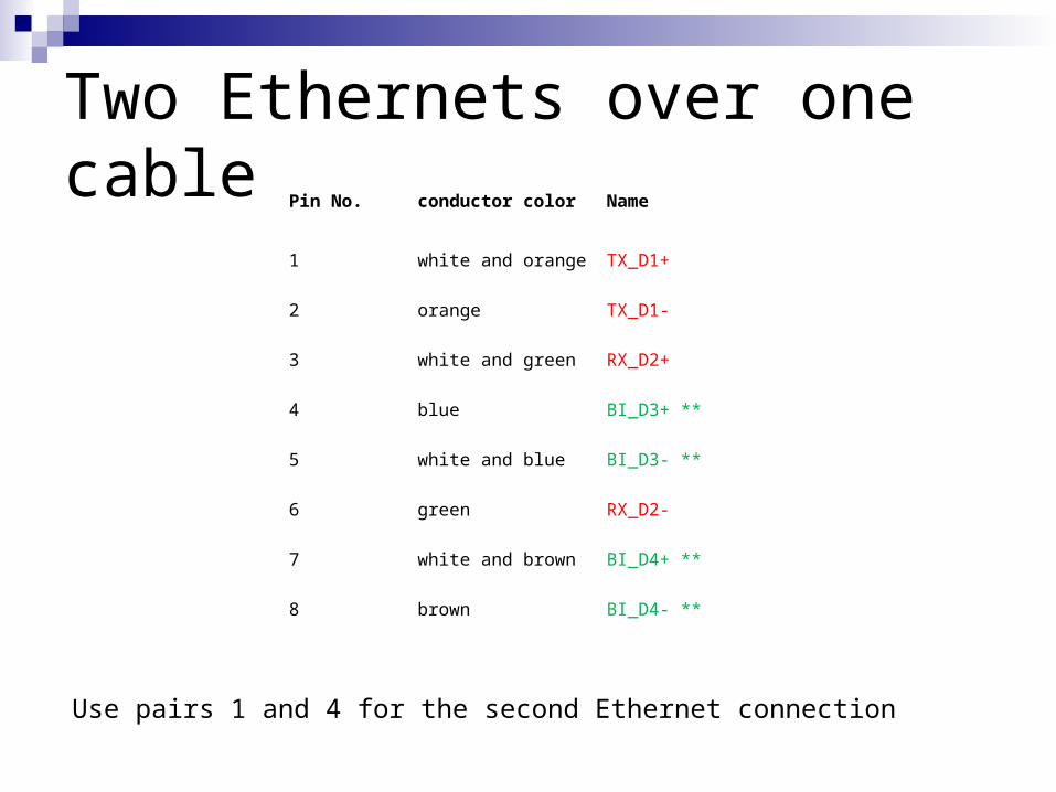
Two Ethernets over one cablePin No. conductor color Name
1 white and orange TX_D1+
2 orange TX_D1-
3 white and green RX_D2+
4 blue BI_D3+ **
5 white and blue BI_D3- **
6 green RX_D2-
7 white and brown BI_D4+ **
8 brown BI_D4- **
Use pairs 1 and 4 for the second Ethernet connection
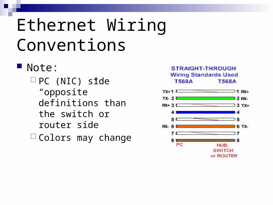
Ethernet Wiring Conventions
Note: PC (NIC) side
“opposite” definitions than the switch or router side
Colors may change
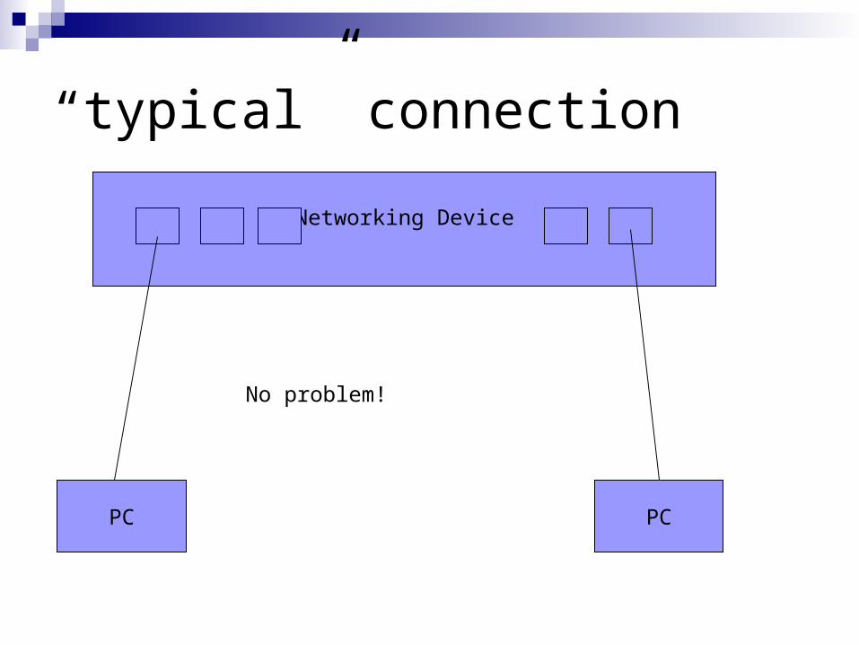
“typical” connection
PC PC
Networking Device
No problem!
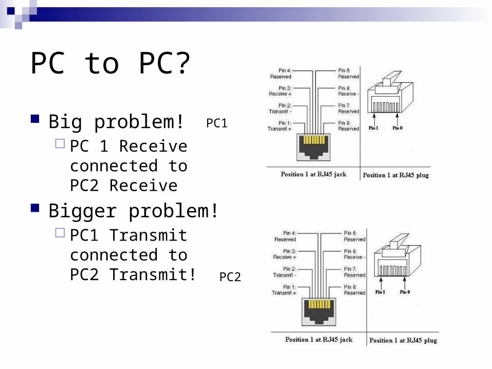
PC to PC?
Big problem! PC 1 Receive
connected toPC2 Receive
Bigger problem! PC1 Transmit
connected to PC2 Transmit!
PC1
PC2
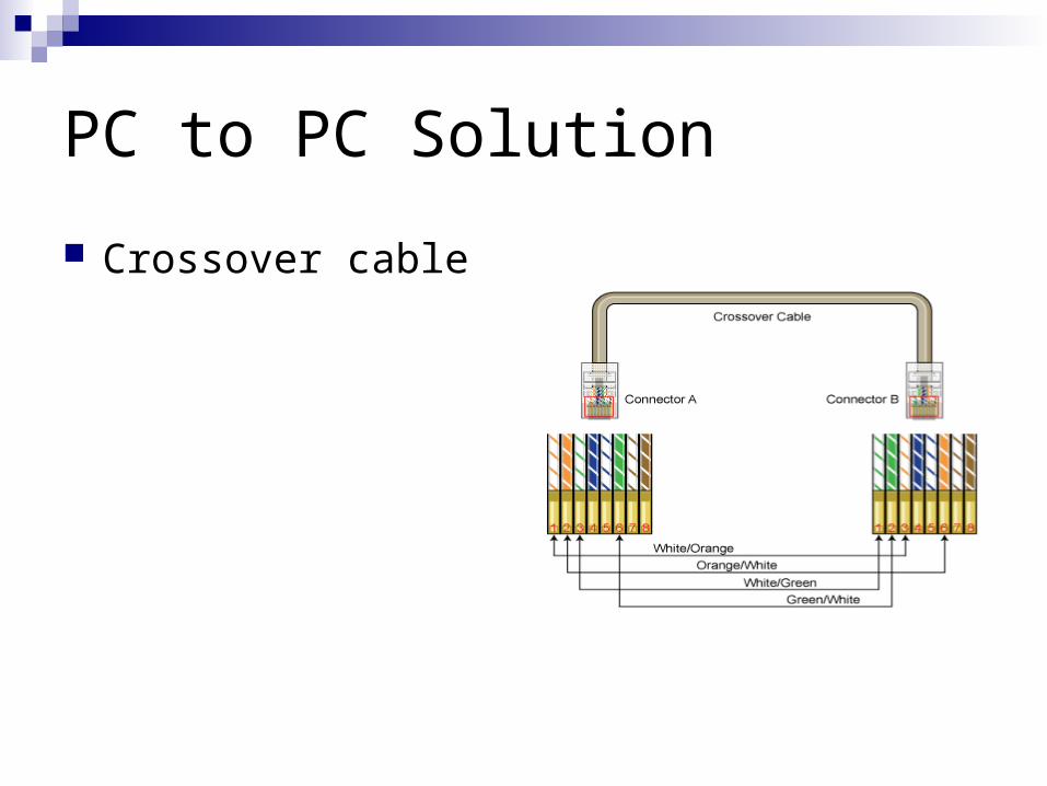
PC to PC Solution
Crossover cable
Auto Sense
Some devices “auto sense” and set up the proper connections