Embed Size (px)
Citation preview
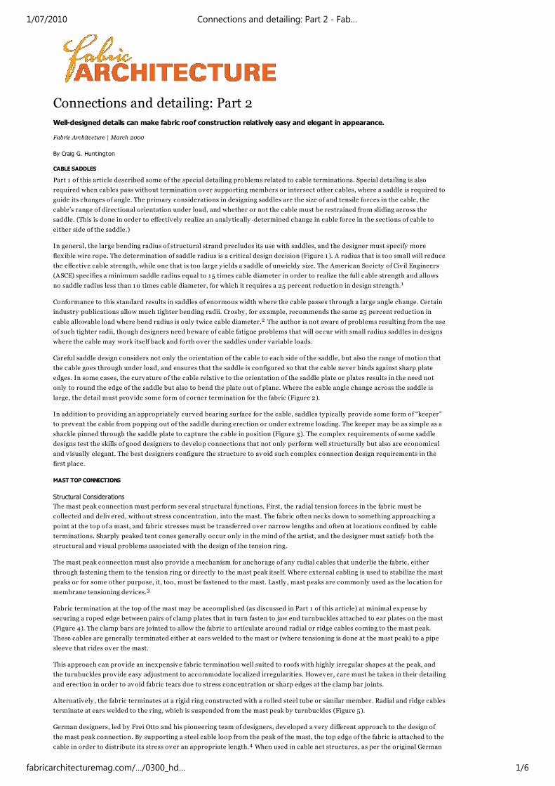
Connections and detailing: Part 2
Well-designed details can make fabric roof construction relatively easy and elegant in appearance.
Fabric Architecture | March 2000
By Craig G. Huntington
CABLE SADDLES
Part 1 of this article described some of the special detailing problems related to cable terminations. Special detailing is also
required when cables pass without termination over supporting members or intersect other cables, where a saddle is required to
guide its changes of angle. The primary considerations in designing saddles are the size of and tensile forces in the cable, the
cable’s range of directional orientation under load, and whether or not the cable must be restrained from sliding across the
saddle. (This is done in order to effectively realize an analytically -determined change in cable force in the sections of cable to
either side of the saddle.)
In general, the large bending radius of structural strand precludes its use with saddles, and the designer must specify more
flex ible wire rope. The determination of saddle radius is a critical design decision (Figure 1). A radius that is too small will reduce
the effective cable strength, while one that is too large y ields a saddle of unwieldy size. The American Society of Civ il Engineers
(ASCE) specifies a minimum saddle radius equal to 15 times cable diameter in order to realize the full cable strength and allows
no saddle radius less than 10 times cable diameter, for which it requires a 25 percent reduction in design strength.1
Conformance to this standard results in saddles of enormous width where the cable passes through a large angle change. Certain
industry publications allow much tighter bending radii. Crosby , for example, recommends the same 25 percent reduction in
cable allowable load where bend radius is only twice cable diameter.2 The author is not aware of problems resulting from the use
of such tighter radii, though designers need beware of cable fatigue problems that will occur with small radius saddles in designs
where the cable may work itself back and forth over the saddles under variable loads.
Careful saddle design considers not only the orientation of the cable to each side of the saddle, but also the range of motion that
the cable goes through under load, and ensures that the saddle is configured so that the cable never binds against sharp plate
edges. In some cases, the curvature of the cable relative to the orientation of the saddle plate or plates results in the need not
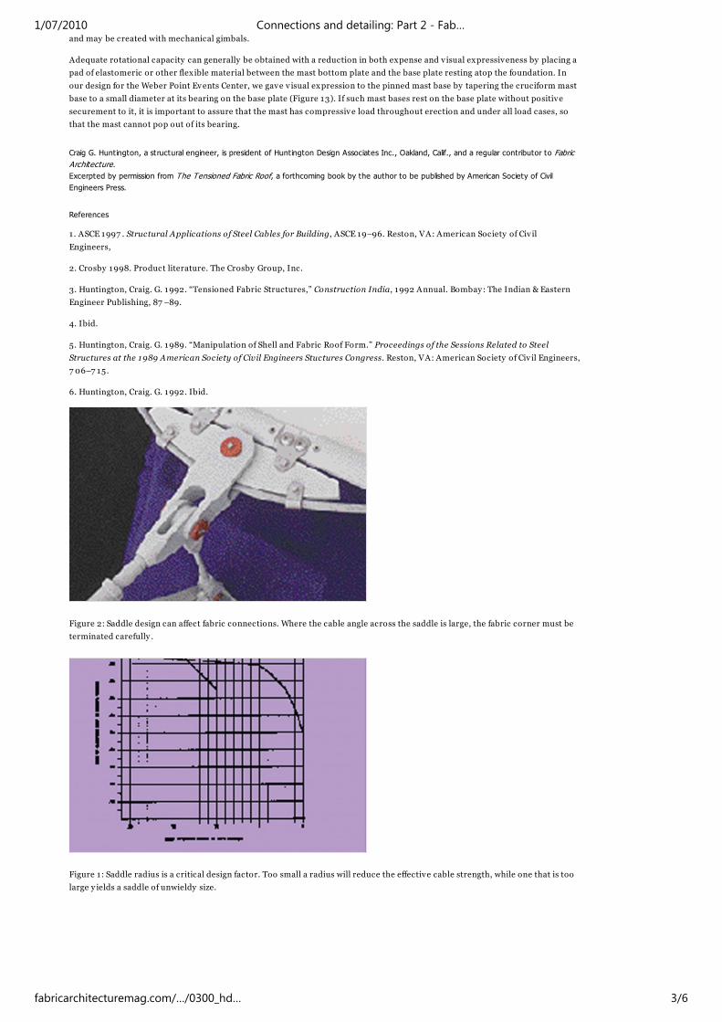
only to round the edge of the saddle but also to bend the plate out of plane. Where the cable angle change across the saddle is
large, the detail must provide some form of corner termination for the fabric (Figure 2).
In addition to providing an appropriately curved bearing surface for the cable, saddles typically provide some form of “keeper”
to prevent the cable from popping out of the saddle during erection or under ex treme loading. The keeper may be as simple as a
shackle pinned through the saddle plate to capture the cable in position (Figure 3). The complex requirements of some saddle
designs test the skills of good designers to develop connections that not only perform well structurally but also are economical
and v isually elegant. The best designers configure the structure to avoid such complex connection design requirements in the
first place.
MAST TOP CONNECTIONS
Structural Considerations
The mast peak connection must perform several structural functions. First, the radial tension forces in the fabric must be
collected and delivered, without stress concentration, into the mast. The fabric often necks down to something approaching a
point at the top of a mast, and fabric stresses must be transferred over narrow lengths and often at locations confined by cable
terminations. Sharply peaked tent cones generally occur only in the mind of the artist, and the designer must satisfy both the
structural and v isual problems associated with the design of the tension ring.
The mast peak connection must also provide a mechanism for anchorage of any radial cables that underlie the fabric, either
through fastening them to the tension ring or directly to the mast peak itself. Where external cabling is used to stabilize the mast
peaks or for some other purpose, it, too, must be fastened to the mast. Lastly , mast peaks are commonly used as the location for
membrane tensioning devices.3
Fabric termination at the top of the mast may be accomplished (as discussed in Part 1 of this article) at minimal expense by
securing a roped edge between pairs of clamp plates that in turn fasten to jaw end turnbuckles attached to ear plates on the mast
(Figure 4). The clamp bars are jointed to allow the fabric to articulate around radial or ridge cables coming to the mast peak.
These cables are generally terminated either at ears welded to the mast or (where tensioning is done at the mast peak) to a pipe
sleeve that rides over the mast.
This approach can prov ide an inexpensive fabric termination well suited to roofs with highly irregular shapes at the peak, and
the turnbuckles provide easy adjustment to accommodate localized irregularities. However, care must be taken in their detailing
and erection in order to avoid fabric tears due to stress concentration or sharp edges at the clamp bar joints.
Alternatively , the fabric terminates at a rigid ring constructed with a rolled steel tube or similar member. Radial and ridge cables
terminate at ears welded to the ring, which is suspended from the mast peak by turnbuckles (Figure 5).
German designers, led by Frei Otto and his pioneering team of designers, developed a very different approach to the design of
the mast peak connection. By supporting a steel cable loop from the peak of the mast, the top edge of the fabric is attached to the
cable in order to distribute its stress over an appropriate length.4 When used in cable net structures, as per the original German
1/07/2010 Connections and detailing: Part 2 - Fab…
fabricarchitecturemag.com/…/0300_hd… 1/6
application, the cables in the net are fixed to the cable loop with clamps in a manner that allows transfer of the tension in the net
into the entire length of the loop. In a pure fabric membrane that terminates in a conventional cable cuff, however, the fabric can
slip down the sides of the loop in a manner that prevents the transfer of membrane tension without stress concentration. Stiff
webbing connected to the mast peak and sewn to the fabric alongside the cable may alleviate the problem. (Figure 3).
Non-Structural Considerations
The mast peak performs important non-structural functions, as well. Sometimes, it is designed to allow ventilation of hot rising
air through the inside of the tension ring (with or without the addition of a cap configured to keep out rainwater), while others
are sealed against both air ventilation and water infiltration. Mast peak design must carefully address aesthetics, as well, because
the mast peak’s position at the top of the structure and its function as the point of transference between membrane tension and
mast compression makes it a v isual singularity whose natural drama ought best to complement the inherent bravura of the cone
form itself.5
The non-structural requirements of the mast peak have been addressed in widely divergent ways on different projects. In 197 3,
Birdair completed installation of the roof of the La Verne University Campus Center, the first structure to use a PTFE-coated
fiberglass fabric roof. As designed by architect The Shaver Partnership and structural engineers Bob D. Campbell and Lin Kulka
Tang & Associates, the finished roof gives no v isual hint of the transfer of load from the fabric and cabling into the mast, because
the entire connection is covered by a steel baffle (Figure 6). The baffle itself, is a cone shaped to continue the curve of the
terminated fabric upward from the tension ring to a sharp peak. The mast peak design reflects a sculptural approach that offers
no clue as to the configuration of the structure that underlies it.
While structurally ambiguous, the LaVerne cones are sculpturally appropriate and pleasing. Other approaches have proven less
so, as at Florida Festival, where the tension ring and mast peak are hidden by a hemispherical glazed dome reminiscent of the
gun turret on a World War II bomber (Figures 7 & 8).
Cable loops can maintain the drama of the sharply peaked cone, where desired, while adding the elegant curve of the loop. The
designs clearly express the collection of fabric tension and its transfer into the mast. However the cable loop has drawbacks
when it is necessary to close off the area within the cable loop to provide a weathertight roof. On some structures, clear acry lic
has been used, but the difficulty of providing a correctly curved edge and maintaining a weathertight seal to the flex ible cable
must be overcome.
Extending the mast up well beyond the top of the fabric and the tension ring has sometimes increased the dramatic impact of the
mast peak. The results often appear contrived. At the stadium in Riyadh, Saudi Arabia (Figure 9), the cy lindrical structural masts
terminate at the elevation of the tension ring. During construction, immediately following the prestressing of the fabric over the
masts, the structure had an elegant but lively beauty . To complete construction, slender mast extensions were secured atop the
tension rings. The daggerlike forms, reminiscent of ancient minarets, are a disappointing addition to the structurally expressive
and modern design, created by architect Ian Fraser and engineers Horst Berger Partners and Schlaich Bergerman & Partners.
The vertical orientation of the Riyadh mast and its ex tension also requires comment. Masts are most efficiently constructed so
that they align with the resultant of the accumulated forces at the peak of the fabric. External cabling to the top of the mast
serves primarily to stabilize it in the event of a strong wind load or a tear in the fabric. At Riyadh, though, the resultant of the
fabric membrane shape pulls markedly inward at its peak while the mast is vertical in order to satisfy non-structural
considerations, so that the external stay cables must perform the additional function of resisting the horizontal resultant force at
the top of the mast.
A highly successful use of the ex tended mast was made on the Independence Mall Pavilion erected in Philadelphia for the 197 6
United States bicentennial (Figure 10). The aesthetic here, as created by architect H2L2 and structural engineer Geiger Berger,
has a strong structural element, as the exposed cabling carries its tension from the fabric to the mast as palpably as a halyard
raising a mainsail.6
Mast Base Connections
The connection at the base of the mast requires only the termination of a single compression member, without the complex ities
of fabric and cable termination that occur at the mast peak. While the technical requirements of the mast base are simple, it too
is an important v isual element in the design, and one whose refinement is made more important by its proximity to v iewers at
grade level.
The fundamental design variable in the mast base design lies in the “degree of freedom” of the connection. Depending on its
configuration, the mast may be fixed in a manner that prevents rotation about its base, or it may be allowed to rotate about one
or both axes of the mast.
Fixed bases have the advantage of allowing the mast to stand vertical like a flagpole during erection, without benefit of any
guy ing cables, and they are appropriate where lateral movements at the top of the mast do not induce excessive bending in the
mast or where it is not possible to use guys or other devices to resist lateral loads at the top of the mast. The most prominent of
all fabric structure fixed mast bases is that on the 17 0m-high tower from which the Montreal Stadium membrane is suspended
(Figure 11). As designed by the French architect Roger Taillibert, the massiveness of this tower relates less to its structural
function than its architectural roles of enclosing space and giv ing form. It is nonetheless a heavy-handed sculptural element, and
ill-suited to the v isually delicate membrane that it supports. On masts of modest size, fixed bases are typically achieved by
welding a steel mast directly to its base plate and securing the base with broadly spaced anchor bolts to a foundation designed
against overturning.
Single degree of freedom bases are useful in applications such as posts at the perimeter of a structure where the roof is tensioned
by shortening tie back cables in a manner that displaces the top of the post outward (Figure 12). In a manner analogous to a
cable jaw end, a single degree of freedom mast base can be achieved by knifing a plate welded vertically to either the mast or the
base plate between a pair of plates welded to the opposing element.
Mast bases with two degrees of freedom allow the top of the member to displace freely about both its axes, as is required when
such displacements may occur either during erection or in serv ice. Bases that are true “pins” may be created with spherical
bearing plates. Mast bases that are stable over wide angle changes about both axes are sometimes required for deployable roofs,
1/07/2010 Connections and detailing: Part 2 - Fab…
fabricarchitecturemag.com/…/0300_hd… 2/6
and may be created with mechanical gimbals.
Adequate rotational capacity can generally be obtained with a reduction in both expense and v isual expressiveness by placing a
pad of elastomeric or other flexible material between the mast bottom plate and the base plate resting atop the foundation. In
our design for the Weber Point Events Center, we gave v isual expression to the pinned mast base by tapering the cruciform mast
base to a small diameter at its bearing on the base plate (Figure 13). If such mast bases rest on the base plate without positive
securement to it, it is important to assure that the mast has compressive load throughout erection and under all load cases, so
that the mast cannot pop out of its bearing.
Craig G. Huntington, a structural engineer, is president of Huntington Design Associates Inc., Oakland, Calif., and a regular contributor to Fabric
Architecture.
Excerpted by permission from The Tensioned Fabric Roof, a forthcoming book by the author to be published by American Society of Civil
Engineers Press.
References
1 . ASCE 1997 . Structural Applications of Steel Cables for Building, ASCE 19–96. Reston, VA: American Society of Civ il
Engineers,
2. Crosby 1998. Product literature. The Crosby Group, Inc.
3. Huntington, Craig. G. 1992. “Tensioned Fabric Structures,” Construction India, 1992 Annual. Bombay: The Indian & Eastern
Engineer Publishing, 87 –89.
4. Ibid.
5. Huntington, Craig. G. 1989. “Manipulation of Shell and Fabric Roof Form.” Proceedings of the Sessions Related to Steel
Structures at the 1989 American Society of Civil Engineers Stuctures Congress. Reston, VA: American Society of Civ il Engineers,
7 06–7 15.
6. Huntington, Craig. G. 1992. Ibid.
Figure 2: Saddle design can affect fabric connections. Where the cable angle across the saddle is large, the fabric corner must be
terminated carefully .
Figure 1 : Saddle radius is a critical design factor. Too small a radius will reduce the effective cable strength, while one that is too
large y ields a saddle of unwieldy size.
1/07/2010 Connections and detailing: Part 2 - Fab…
fabricarchitecturemag.com/…/0300_hd… 3/6
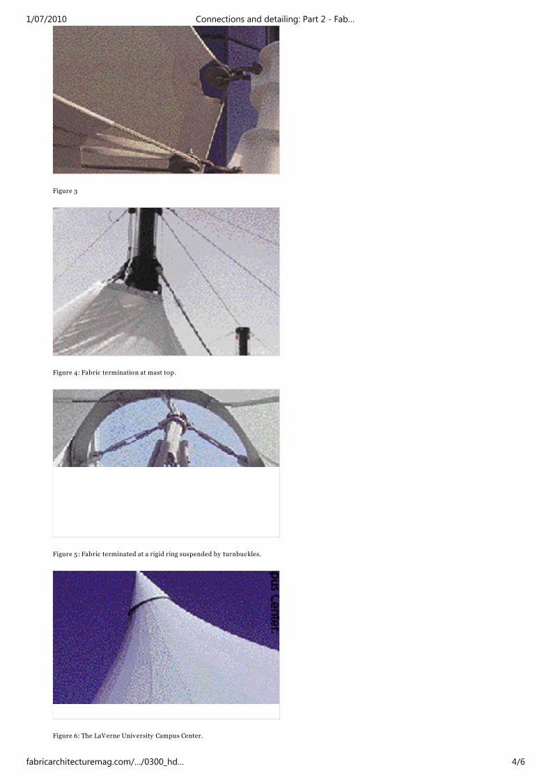
Figure 3
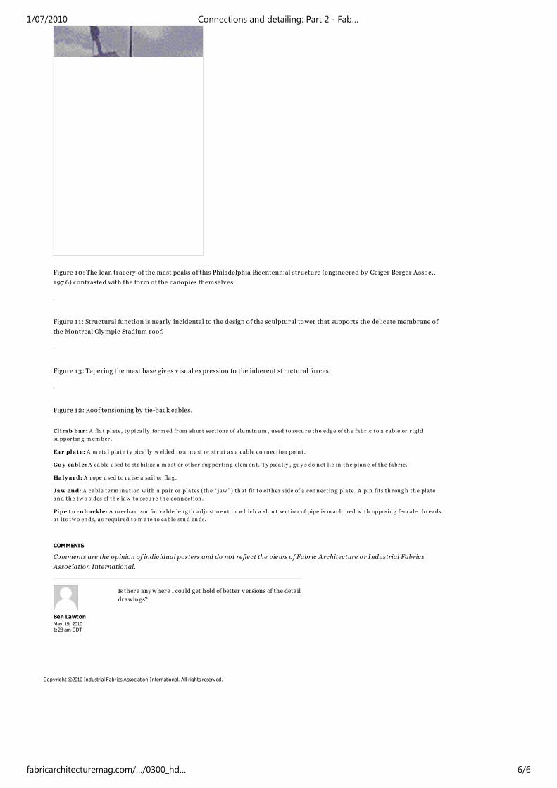
Figure 4: Fabric termination at mast top.
Figure 5: Fabric terminated at a rigid ring suspended by turnbuckles.
Figure 6: The LaVerne University Campus Center.
1/07/2010 Connections and detailing: Part 2 - Fab…
fabricarchitecturemag.com/…/0300_hd… 4/6
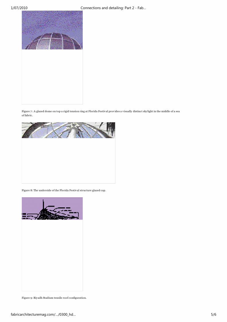
Figure 7 : A glazed dome on top a rigid tension ring at Florida Festival prov ides a v isually distinct sky light in the middle of a sea
of fabric.
Figure 8: The underside of the Florida Festival structure glazed cap.
Figure 9: Riyadh Stadium tensile roof configuration.
1/07/2010 Connections and detailing: Part 2 - Fab…
fabricarchitecturemag.com/…/0300_hd… 5/6
Ben Lawton
May 19, 20101:28 am CDT
Figure 10: The lean tracery of the mast peaks of this Philadelphia Bicentennial structure (engineered by Geiger Berger Assoc.,
197 6) contrasted with the form of the canopies themselves.
Figure 11 : Structural function is nearly incidental to the design of the sculptural tower that supports the delicate membrane of
the Montreal Olympic Stadium roof.
Figure 13: Tapering the mast base gives v isual expression to the inherent structural forces.
Figure 12: Roof tensioning by tie-back cables.
Climb bar: A fla t pla te, ty pica lly form ed from shor t sect ions of a lum inum , u sed to secu re the edge of th e fabr ic to a cable or r ig id
suppor t in g m em ber .
Ear pla te: A m eta l pla te ty pica lly w elded to a m ast or str u t a s a cable connect ion poin t .
Guy cable: A cable u sed to stabilize a m ast or other suppor t ing elem en t. Ty pica lly , gu y s do not lie in th e plane of the fabr ic.
Halyard: A rope u sed to r a ise a sa il or flag .
Jaw end: A cable term ina tion w ith a pa ir or pla tes (the “ jaw ”) tha t fit to either side of a connect ing pla te. A pin fits th rou gh the pla te
and the tw o sides of th e jaw to secu r e the connect ion .
Pipe turnbuckle: A m echan ism for cable leng th adju stm ent in wh ich a shor t sect ion of pipe is m ach ined w ith opposing fem a le th reads
a t its tw o ends, a s r equ ired to m ate to cable stu d ends.
COMMENTS
Comments are the opinion of individual posters and do not reflect the views of Fabric Architecture or Industrial Fabrics
Association International.
Is there anywhere I could get hold of better v ersions of the detail
drawings?
Copyright ©2010 Industrial Fabrics Association International. All rights reserved.
1/07/2010 Connections and detailing: Part 2 - Fab…
fabricarchitecturemag.com/…/0300_hd… 6/6