Embed Size (px)
Citation preview
CONNECTIONLESS INTER-DOMAINTRAFFIC ENGINEERING
By
Mehul Doshi
A Thesis Submitted to the Graduate
Faculty of Rensselaer Polytechnic Institute
in Partial Fulfillment of the
Requirements for the Degree of
MASTER OF SCIENCE
Approved:
Prof. Shivkumar KalyanaramanThesis Adviser
Rensselaer Polytechnic InstituteTroy, New York
August 2002(For Graduation August 2002)
CONTENTS
LIST OF TABLES . . . . . . . . . . . . . . . . . . . . . . . . . . . . . . . . . iv
LIST OF FIGURES . . . . . . . . . . . . . . . . . . . . . . . . . . . . . . . . v
ACKNOWLEDGMENT . . . . . . . . . . . . . . . . . . . . . . . . . . . . . . vi
ABSTRACT . . . . . . . . . . . . . . . . . . . . . . . . . . . . . . . . . . . . vii
1. Introduction . . . . . . . . . . . . . . . . . . . . . . . . . . . . . . . . . . . 1
2. Inter-Domain TE and Routing Models . . . . . . . . . . . . . . . . . . . . 2
2.1 Hop-by-Hop vs Signaled Routing Models . . . . . . . . . . . . . . . . 2
2.2 Inter-Domain Traffic Engineering . . . . . . . . . . . . . . . . . . . . 4
3. Connectionless Framework for Inter-Domain TEThe Building Blocks . . . . . . . . . . . . . . . . . . . . . . . . . . . . . . 7
3.1 PathID concept . . . . . . . . . . . . . . . . . . . . . . . . . . . . . . 7
3.1.1 PathID vs MPLS Labels . . . . . . . . . . . . . . . . . . . . . 7
3.1.2 PathID Uniqueness . . . . . . . . . . . . . . . . . . . . . . . . 8
3.2 Forwarding Concepts . . . . . . . . . . . . . . . . . . . . . . . . . . . 9
4. Explicit Forwarding in BGP . . . . . . . . . . . . . . . . . . . . . . . . . . 11
4.1 Explicit AS-Path Forwarding . . . . . . . . . . . . . . . . . . . . . . 11
4.2 Explicit Exit Forwarding . . . . . . . . . . . . . . . . . . . . . . . . . 13
4.3 Partial Upgrade Implementation . . . . . . . . . . . . . . . . . . . . . 15
5. Control Plane Issues . . . . . . . . . . . . . . . . . . . . . . . . . . . . . . 19
5.1 Explicit AS-Path Routing: Re-advertisement & Synchronization . . . 19
5.2 Explicit Exit Routing . . . . . . . . . . . . . . . . . . . . . . . . . . . 20
6. Pseudo-code . . . . . . . . . . . . . . . . . . . . . . . . . . . . . . . . . . . 21
7. Conclusions . . . . . . . . . . . . . . . . . . . . . . . . . . . . . . . . . . . 24
LITERATURE CITED . . . . . . . . . . . . . . . . . . . . . . . . . . . . . . 25
APPENDICES
A. Modified IP Header format . . . . . . . . . . . . . . . . . . . . . . . . . . . 27
ii

B. SSFNet . . . . . . . . . . . . . . . . . . . . . . . . . . . . . . . . . . . . . 28
B.1 Implementation Hurdles and Difficulties . . . . . . . . . . . . . . . . 28
iii
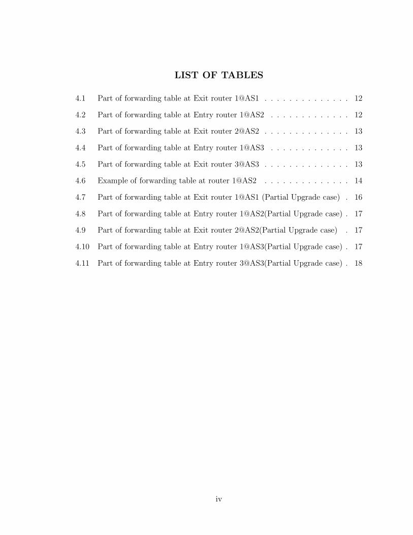
LIST OF TABLES
4.1 Part of forwarding table at Exit router 1@AS1 . . . . . . . . . . . . . . 12
4.2 Part of forwarding table at Entry router 1@AS2 . . . . . . . . . . . . . 12
4.3 Part of forwarding table at Exit router 2@AS2 . . . . . . . . . . . . . . 13
4.4 Part of forwarding table at Entry router 1@AS3 . . . . . . . . . . . . . 13
4.5 Part of forwarding table at Exit router 3@AS3 . . . . . . . . . . . . . . 13
4.6 Example of forwarding table at router 1@AS2 . . . . . . . . . . . . . . 14
4.7 Part of forwarding table at Exit router 1@AS1 (Partial Upgrade case) . 16
4.8 Part of forwarding table at Entry router 1@AS2(Partial Upgrade case) . 17
4.9 Part of forwarding table at Exit router 2@AS2(Partial Upgrade case) . 17
4.10 Part of forwarding table at Entry router 1@AS3(Partial Upgrade case) . 17
4.11 Part of forwarding table at Entry router 3@AS3(Partial Upgrade case) . 18
iv

LIST OF FIGURES
4.1 TE Simulation Topology model in SSFnet[13] . . . . . . . . . . . . . . . 12
4.2 Example of Explicit Exit Forwarding . . . . . . . . . . . . . . . . . . . 14
4.3 TE Simulation Topology model in SSFnet[13]– Partial Upgrade case . . 16
A.1 Modified IP header . . . . . . . . . . . . . . . . . . . . . . . . . . . . . 27
v

ACKNOWLEDGMENT
I am greatly indebted to Prof. Shivkumar Kalyanaraman. Prof. Shiv, as we fondly
call him, for being my inspiration and guide. He has been the key driving force in
steering me towards completion of this work.
I wish to sincerely thank B.J.Premore of SSFnet for his help and suggestions
at various points in time. I also wish to sincerely thank my colleague Andreas Weiss
for joining forces with me to try and change SSFnet modules. Together we were
able to cross many implementation hurdles. It would have been very tough to have
achieved it without his help and support.
I also wish to show my appreciation to all my project members Ayesha Gandhi,
Shifalika Kanwar, Hemang Nagar, Niharika Mateti and Hema Kaur for their valuable
inputs from time to time. I also wish to take this opportunity to thank all the
members of Networks and Testbed labs for being such wonderful friends who helped
out whenever in need of ideas and gave valuable suggestions.
Last but not the least, a big thanks to my family and friends both here and
back in India who have boosted my confidence and helped me come so far.
vi
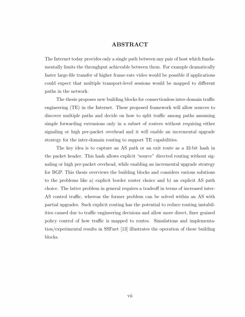
ABSTRACT
The Internet today provides only a single path between any pair of host which funda-
mentally limits the throughput achievable between them. For example dramatically
faster large-file transfer of higher frame-rate video would be possible if applications
could expect that multiple transport-level sessions would be mapped to different
paths in the network.
The thesis proposes new building blocks for connectionless inter-domain traffic
engineering (TE) in the Internet. These proposed framework will allow sources to
discover multiple paths and decide on how to split traffic among paths assuming
simple forwarding extensions only in a subset of routers without requiring either
signaling or high per-packet overhead and it will enable an incremental upgrade
strategy for the inter-domain routing to support TE capabilities.
The key idea is to capture an AS path or an exit route as a 32-bit hash in
the packet header. This hash allows explicit “source” directed routing without sig-
naling or high per-packet overhead, while enabling an incremental upgrade strategy
for BGP. This thesis overviews the building blocks and considers various solutions
to the problems like a) explicit border router choice and b) an explicit AS path
choice. The latter problem in general requires a tradeoff in terms of increased inter-
AS control traffic, whereas the former problem can be solved within an AS with
partial upgrades. Such explicit routing has the potential to reduce routing instabil-
ities caused due to traffic engineering decisions and allow more direct, finer grained
policy control of how traffic is mapped to routes. Simulations and implementa-
tion/experimental results in SSFnet [13] illustrates the operation of these building
blocks.
vii

CHAPTER 1
Introduction
Traffic Engineering (TE) is defined as “...that aspect of Intenet network engineering
dealing with the issue of performance evaluation and performance optimization of
operational IP networks...” [2]. The term “traffic engineering” (TE) has been used
to imply a range of objectives, including but not limited to load-balancing [3, 4],
constraint-based routing,[5, 6], multi-path routing [7], fast re-routing and protection
switching [15]. Most work in TE has focussed on solving one or more of the above
problems within a single, flat routing domain or area.
This research is based on a new connectionless framework, called BANANAS
[1], that allows the incremental deployment of TE capabilities for both intra-domain
and inter-domain settings within the hop-by-hop(or connectionless) routing model
on the Internet. However this thesis focusses primarily on the Inter-domain connec-
tionless routing model. The objective of the TE is primarily of efficient utilization of
network resources by using multi-path routing. The solution consists of multi-path
computation and forwarding (at intermediate nodes) and multi-path computation
(or discovery) and traffic splitting (at the source.)1 With partial upgrades, a sub-
set of sources can benefit from these capabilities. With a fully upgraded network,
every source can control how traffic is mapped to paths and therefore network-wide
objectives can be achieved. This thesis presents an SSFNet [13] implementation of
the fully upgraded case.
1“Source” refers to some node in the data-path that takes multi-path computation (or discovery)and traffic-splitting decisions on behalf of the traffic originator (i.e. source host). Upgradedintermediate nodes provide next-hop forwarding to implement the source’s path selection decision.
1

CHAPTER 2
Inter-Domain TE and Routing Models
BGPv4 is the Inter-domain routing protocol in the Internet. It is a path vector
protocol which announces paths to a destination prefix if the AS is actively using
those paths. One of the goals of this research was to enable multi-AS paths from
the source to the destination. Within each transit AS, multi-paths may be chosen
under the control of the entry border router (entry AS-BR).
A single AS can be extended to autonomously support multi-AS-path forward-
ing. It can then leverage BGP to advertise multiple AS paths (to any destination
prefix) to its neighbor ASs. Therefore any AS can infer that its neighbor AS has
multi-AS-path capabilities merely from the fact that it is advertising multiple AS-
paths (and that the neighbor AS is the forking point for the multi-AS paths) to the
destination prefix of interest.
Moreover, since BGPv4 is a path-vector protocol, the multi-path computation
algorithm extension at any BGP router is trivial. Today, BGPv4 applies policies as a
series of tie-breaker rules to choose one route to a prefix. A multi-path computation
extension would allow multiple paths to be chosen after they are pre-qualified by a
set of filtering rules. But upgrading a single BGP router in an AS is not sufficient.
BGP expects synchronization between all i-BGP and e-BGP routers in an AS before
routes can be advertised outside the AS. Also, because of the DV-nature of BGP, the
multi-AS-path information may not be propagated beyond the immediate neighbors
of a multi-AS-path enabled AS. This is because such neighbor AS’s may not support
multi-path forwarding. The following chapters propose solutions to address the
above issues.
2.1 Hop-by-Hop vs Signaled Routing Models
Two broad classes of routing models dominate the current debate on next-
generation routing and traffic engineering: hop-by-hop model 2 (distance-vector
2a.k.a the connectionless model in BANANAS [1] paper
2

3
(DV), path-vector (PV) and link-state (LS)) and signaled model (implemented in
technologies like MPLS, ATM and frame-relay).
In the hop-by-hop model, local knowledge is distributed to immediate neigh-
bors, and ultimately reaches all nodes. Every node infers routes based upon this
information. A consistency criterion ensures that the independent decisions made
by nodes lead to valid, loop-free routes. The forwarding algorithm in this model is
related to the control-plane algorithm because both use the same global identifiers
(e.g. addresses, prefixes, link metrics, AS numbers). This relationship has, in the
past, required changes in the forwarding algorithm whenever the control-plane algo-
rithm was significantly changed (e.g. subnet masking, CIDR). However, hop-by-hop
routing protocols dominate the control-plane of the Internet (e.g. RIP, EIGRP,
OSPF, IS-IS, BGP) for three important reasons (a) They support connectionless
forwarding, (b) They can be inter-networked easily and (c) They scale reasonably
well.
Traffic engineering capabilities in the hop-by-hop model, though attempted
[7], have not found wide adoption in the Internet. Source routing in this model has
typically meant that the entire path is enumerated in the packet – an undesirable
overhead (e.g. IP, IPv6 options for strict/loose source route). Multi-path algorithms
for this model (eg: [7]) have usually required the cooperation and upgrade of all
routers in the network; and the decision of traffic-splitting is typically done in an
ad-hoc manner at intermediate nodes without source control.
In the signaled model, local knowledge may be sent to all nodes through an
approach similar to hop-by-hop algorithms. However, it is the source node or some
central entity that, a) computes the desired paths and, b) decides what traffic is
mapped to those paths. The intermediate nodes (switches) then set up local path
identifiers (called “labels” in MPLS) for the paths. The signaling protocol allows
autonomy in the choice of labels at switches, but ensures the consistency between
label assignments at adjacent switches in the path. This leads to a label-switching
forwarding algorithm where labels are switched at every hop. The forwarding al-
gorithm in the signaled model is de-coupled from the control algorithms. This is
because the forwarding algorithm uses local identifiers (labels), whereas the con-

4
trol algorithms use global identifiers (addresses). The signaling protocol maps and
ensures consistency between local and global identifiers. This de-coupling between
forwarding and control-planes allows the introduction of new TE capabilities (e.g.
multi-path routing, traffic splitting, path protection) by modifying the control plane
alone. However, signaled approaches have historically been hard to inter-network
(e.g. IP over ATM [9], or multi-domain signaled TE), and hence have been limited
to intra-domain or intra-area deployments (e.g. MPLS, ATM).
The key reasons for the lag in adoption of connectionless TE capabilities in-
clude the need for complete network upgrades, lack of source-based or explicit op-
erator control over TE decisions, lack of a common reference framework that allows
long-term evolution of TE capabilities. The proposed BANANAS[1] framework
promises to fill these needs.
• A framework, called BANANAS[1], which allows sources to compute (or discover)
multiple paths within the connectionless routing model and decide on how to split
traffic among these paths.
• Allowing a subset of nodes to participate in the TE process, i.e., allowing some
TE capabilities with partial upgrades.
• Developing a simple and efficient path encoding to specify the path as a short,
fixed-length field in a packet; and a corresponding forwarding algorithm.
• Mapping the BANANAS[1] framework to current inter-domain protocols viz.
BGPv4.
• Examining preliminary options for various sub-blocks of this framework (eg: multi-
path and traffic splitting algorithms for partially upgraded networks)
The BANANAS[1] framework is an attempt to provide an incremental upgrade
strategy for connectionless TE, and to support a broad set of TE capabilities for the
inter-domain case in the Internet.
2.2 Inter-Domain Traffic Engineering
Inter-domain protocols of the Internet were not originally designed with the
goals of TE. However they provided some hooks for gaining limited TE function-
ality. This section presents a brief overview of prior inter-domain TE work which

5
includes in-bound/out-bound load-balancing between adjacent AS’s using BGP at-
tributes(eg: MED, LOCAL PREF, stuffed AS-PATHs)[10].
BGPv4 [11]provides some simple hooks for TE between neighbors [10]. The
MED attribute can be used by an AS to inform its neighbor of a preference among
multiple physical connections for inbound traffic to a particular address prefix. Usu-
ally it is used by ISPs on the request of their customers who are multi-homed to
it. Lately, it is also being used between ISPs. The LOCAL PREF attribute is
used locally within the AS to prefer an outbound direction for a chosen address
prefix, AS or exit router. Recent work by our group [12] shows that it is possible
to automatically tune the LOCAL PREF parameters of “hot-prefixes” to control
outbound traffic subject to a range of policy constraints. The AS-PATH attribute
in BGP provides another TE hook. The AS-PATH attribute may be “stuffed” or
“padded” with additional instances of the same ASN to increase its length to lower
the expected amount of inbound traffic from the neighbor AS to whom the attribute
is announced.
Another way to leverage inbound TE functionality in BGP is to subvert the
BGP-CIDR address aggregation process. In particular an AS may take an address
aggregate, “punch address holes” in it (i.e. extract more-specifics, or de-aggregate
it) and re-advertise the more-specifics to other AS’s. The longest-prefix match rule
in IP forwarding will lead to a different route for the “punched address hole” at the
expense of larger entries in the forwarding tables. Our work [12] shows a way of
subverting CIDR aggregation in the case of multi-homed stub AS’s. The idea is to
map the inbound load-balancing problem as an address management problem. In
particular, chosen flows can be assigned or internal address aggregates to different
inbound links(or inbound providers) by chosing public address from that provider’s
allocation for the chosen flows. The dynamic mapping between the chosen public
address and the private address of the flow can be done through dynamic NAT. In
short BGP is completely avoided for the particular case.
In summary, BGP is an example of a tunable Internet routing protocol that
was not originally designed for traffic engineering, but some limited TE capabilities
can be leveraged by careful parameter tuning. The signaled protocols that use a

6
label-swapping paradigm are hard to map to such protocols.

CHAPTER 3
Connectionless Framework for Inter-Domain TE
The Building Blocks
The framework allows for partial upgrade of intermediate nodes to support multi-
path computation and multi-path forwardingand partial upgrade of sources to support
multi-path computation (or discovery)and traffic splitting strategies. The “source”
is a node in the data-path that takes multi-path discovery/traffic-splitting decisions
on behalf of the traffic originator (i.e. source host) and has some visibility into
the available paths in the network. The following sub-sections introduce abstract
forwarding-plane concepts (such as paths, path suffixes and path identifier), develop
a forwarding algorithm based upon these concepts, and compare these concepts to
labels in the signaled routing model.
3.1 PathID concept
The PathID concept [14] introduced in the Bananas [1] paper comes largely
from the needs of the connectionless inter-domain requirements as shown in [14].
Below shown is a comparison of the notion of PathID to the notion of “label” used
in the signaled models such as ATM and MPLS.
3.1.1 PathID vs MPLS Labels
• The forwarding tuple (destination address, PathID) can be thought of as a
globally significant path identifier, just like an IP address is a globally signif-
icant interface ID and an IP prefix is a globally significant network ID. In
contrast, the MPLS label has only a local meaning, requiring a signaling pro-
tocol to map labels to global addresses. The signaling requirement makes it
hard to map a label-swapped routing system to BGP. A caveat is that unlike
addresses, non-unique forwarding tuples are possible with low probability.
• The PathID field by itself does not designate the path; it needs to be inter-
7

8
preted along with the destination address. In contrast, the label is a stand-
alone field.
• Both PathID and labels are updated at every (upgraded) hop. But PathID
is updated through a computation (subtract operation) whereas a label is
swapped with a completely new label entry based upon a table entry.
• Since PathID can be defined in terms of ASNs, it can be mapped to inter-
domain protocol with minor modifications as discussed in later sections. In
contrast, the label-swapping and the signaled model are hard to map to current
inter-domain protocols (BGPv4).
• Though the use of the (Destination address, PathID) tuple still relates the
forwarding and control planes due to the use of global IDs, it gives a valuable
handle (global path identifier) for TE functions. Given this handle, a range
of future TE control-plane functions may be deployed without any further
forwarding-plane support at intermediate nodes. Recall that in MPLS, the
use of local IDs (labels) for forwarding and global IDs (addresses) for control
de-couples the two planes, and allows deployment of new TE control functions
without affecting the forwarding plane.
3.1.2 PathID Uniqueness
Consider a network of links and nodes, where links are given weights(not nec-
essarily unique). Consider a path from node i to node j, which passes through nodes
i, 1, 2, ..., m− 1, j and links of weights w1, w2, ..., wm. This path can be represented
as a sequence of: [i, w1, 1, w2, ...wm, j], and path suffix of this path from node k
to j represented as the sequence: [k, wk + 1, ..., wm, j]. This path sequence can be
parsimoniously represented by a hash function of the elements of the sequence (or
subsequence). These concepts are illustrated in figure in [8].
In the case of BGP, we are interested in choosing explicit AS-paths, then
the node ID’s above could also be considered as the AS numbers(ASNs) which
are well known for each AS-path that is available. If we are interested in an exit
AS-border router (a.k.a. Exit ASBR), then the hash is simply the exit-ASBR IP

9
address. Hashing such a sequence of globally known quantities allows us to avoid
signaling because each upgraded router on the path can unambiguously interpret
the hash. Recall that one purpose of signaling in ATM and MPLS is to map global
IDs (addresses, path specifications) to local IDs (labels). Since we obtain our local
IDs from the global IDs through the hashing procedure, signaling for path selection
is not necessary.
The choice of the hash function is dictated by the need to minimize the collision
probability which directly affects the uniqueness and utility of the hash. A simple
hash of the path sequence is the sum of the link weights, but it may lead to a
high collision probability. Therefore the hash proposed is a 128 bit MD5 hash of the
sequence of ASNs in the path, followed by a 32-bit CRC of the 128 bit MD5 to result
in a 32 bit hash field. For the exit router choice, the hash is simply the IP address
of the exit ASBR. Based on the above it is safe to assume that the forwarding tuples
(Destination, PathID) are unique.
3.2 Forwarding Concepts
The abstract forwarding concept is as follows: Routers which are not upgraded
have forwarding table entries of the form [destination prefix, outgoing interface],
as usual. Upgraded routers have forwarding table entries of the form[destination
prefix, incoming hash, outgoing interface, outgoing hash]. The “incoming hash”
field represents the hash of the explicit path starting from the current router to the
destination prefix. The “outgoing hash” field is the hash of the path suffix from
the next upgraded router on the explicit path to the destination. Incoming packets
at the upgraded routers may come with a pathID = [j, hash] if an explicit path is
chosen for the packet or with a regular destination address field j and no hash field.
The hash field may be stored in a new routing header in IP packets.
The router first matches the destination IP address using the longest prefix
match procedure, and then it does an exact match of the hash for that destination. If
matched, the hash in the packet is replaced with the outgoing hash, and the packet
is sent to the outgoing interface. It is basically a hybrid of IP’s longest prefix match
and MPLS’s label swapping, but using the hash instead of labels and without the

10
need for signaling. If the exact match is not found (i.e. errant hash value in the
packet), then the hash value of the packet is set to zero and the packet is sent on
the default path based on the default policy route.
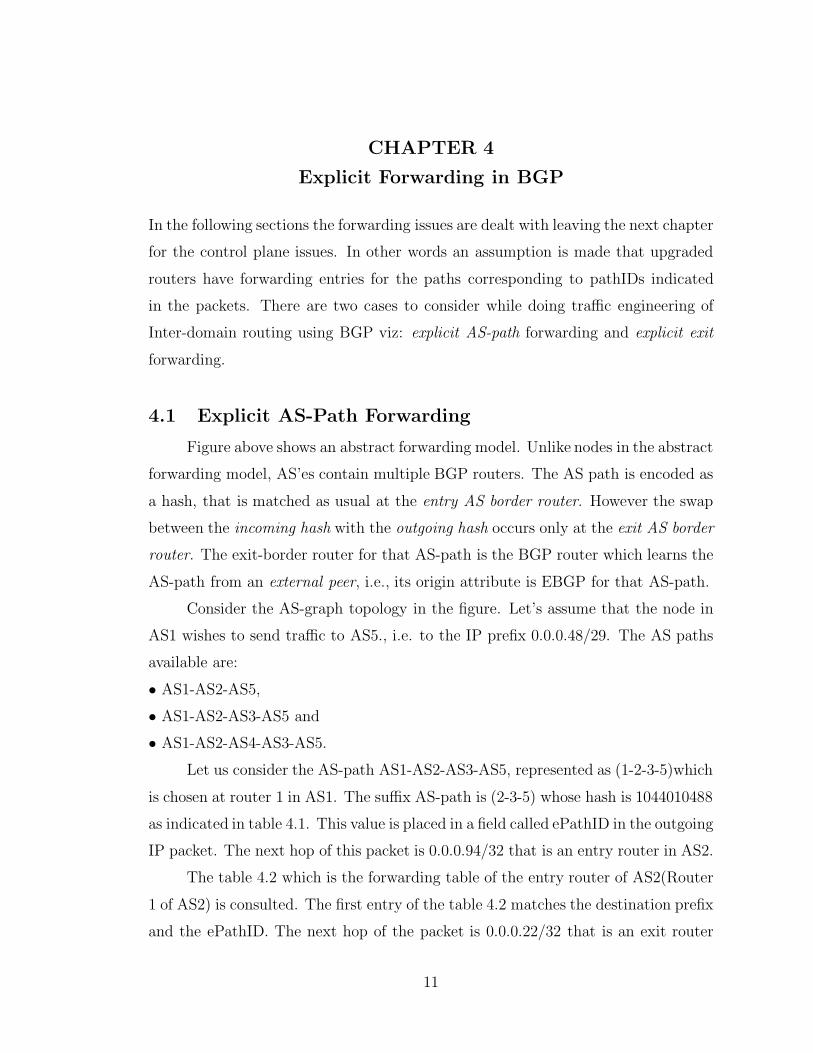
CHAPTER 4
Explicit Forwarding in BGP
In the following sections the forwarding issues are dealt with leaving the next chapter
for the control plane issues. In other words an assumption is made that upgraded
routers have forwarding entries for the paths corresponding to pathIDs indicated
in the packets. There are two cases to consider while doing traffic engineering of
Inter-domain routing using BGP viz: explicit AS-path forwarding and explicit exit
forwarding.
4.1 Explicit AS-Path Forwarding
Figure above shows an abstract forwarding model. Unlike nodes in the abstract
forwarding model, AS’es contain multiple BGP routers. The AS path is encoded as
a hash, that is matched as usual at the entry AS border router. However the swap
between the incoming hash with the outgoing hash occurs only at the exit AS border
router. The exit-border router for that AS-path is the BGP router which learns the
AS-path from an external peer, i.e., its origin attribute is EBGP for that AS-path.
Consider the AS-graph topology in the figure. Let’s assume that the node in
AS1 wishes to send traffic to AS5., i.e. to the IP prefix 0.0.0.48/29. The AS paths
available are:
• AS1-AS2-AS5,
• AS1-AS2-AS3-AS5 and
• AS1-AS2-AS4-AS3-AS5.
Let us consider the AS-path AS1-AS2-AS3-AS5, represented as (1-2-3-5)which
is chosen at router 1 in AS1. The suffix AS-path is (2-3-5) whose hash is 1044010488
as indicated in table 4.1. This value is placed in a field called ePathID in the outgoing
IP packet. The next hop of this packet is 0.0.0.94/32 that is an entry router in AS2.
The table 4.2 which is the forwarding table of the entry router of AS2(Router
1 of AS2) is consulted. The first entry of the table 4.2 matches the destination prefix
and the ePathID. The next hop of the packet is 0.0.0.22/32 that is an exit router
11

12
Figure 4.1: TE Simulation Topology model in SSFnet[13]
Dst NextHop Learnt ePathID AS-Path OutgoingFrom ePathID
0.0.0.48/29 0.0.0.94/32 EBGP 1996809222 2 5 40383367210.0.0.48/29 0.0.0.94/32 EBGP 1473492148 2 3 5 10440104880.0.0.48/29 0.0.0.94/32 EBGP 1272272860 2 4 3 5 3884942939
Table 4.1: Part of forwarding table at Exit router 1@AS1
from AS2 to reach AS3.
Dst NextHop Learnt ePathID AS-Path OutgoingFrom ePathID
0.0.0.48/29 0.0.0.22/32 IBGP 1044010488 2 3 5 10440104880.0.0.48/29 0.0.0.10/32 IBGP 4038336721 2 5 40383367210.0.0.48/29 0.0.0.18/32 IBGP 3884942939 2 4 3 5 3884942939
Table 4.2: Part of forwarding table at Entry router 1@AS2
The table 4.3 which is the forwarding table of the exit router of AS2 to reach
AS3(i.e. Router 2 of AS2) is consulted. The first entry of the table 4.3 matches the
destination prefix and the ePathID. The next hop of the packet is 0.0.0.90/32 that
is an entry router from AS2 to AS3.
The table 4.4 which is the forwarding table of the entry router of AS3(Router

13
Dst NextHop Learnt ePathID AS-Path OutgoingFrom ePathID
0.0.0.48/29 0.0.0.90/32 EBGP 1044010488 3 5 15722061470.0.0.48/29 0.0.0.2/32 IBGP 4038336721 2 5 40383367210.0.0.48/29 0.0.0.14/32 IBGP 3884942939 2 4 3 5 3884942939
Table 4.3: Part of forwarding table at Exit router 2@AS2
1 of AS3) is consulted. The second entry of the table 4.4 matches the destination
prefix and the ePathID. The next hop of the packet is 0.0.0.38/32 that is an exit
router from AS3 to reach AS5.
Dst NextHop Learnt ePathID AS-Path OutgoingFrom ePathID
0.0.0.48/29 0.0.0.89/32 EBGP 2195846196 2 5 40383367210.0.0.48/29 0.0.0.38/32 IBGP 1572206147 3 5 15722061470.0.0.48/29 0.0.0.42/32 IBGP 1398088657 3 4 2 5 1398088657
Table 4.4: Part of forwarding table at Entry router 1@AS3
The table 4.5 which is the forwarding table of the exit router of AS3 to reach
AS5(i.e. Router 3 of AS3) is consulted. The second entry of the table 4.5 matches
the destination prefix and the ePathID. The next hop of the packet is 0.0.0.77/32
that is an entry router from AS3 to AS5.
Dst NextHop Learnt ePathID AS-Path OutgoingFrom ePathID
0.0.0.48/29 0.0.0.37/32 IBGP 2195846196 3 2 5 21958461960.0.0.48/29 0.0.0.77/32 EBGP 3690458478 5 00.0.0.48/29 0.0.0.33/32 IBGP 1398088657 3 4 2 5 1398088657
Table 4.5: Part of forwarding table at Exit router 3@AS3
4.2 Explicit Exit Forwarding
A simplifying assumption made in previous section is that the entry ASBR is
directly connected to the Exit ASBR. If not, the packet needs to be sent explicitly to
the Exit ASBR. In this section, consider the problem of explicitly routing a packet
from either an EBGP router or an IBGP router to an Exit ASBR. One simple way

14
Figure 4.2: Example of Explicit Exit Forwarding
of accomplishing this objective is through IP-in-IP tunneling, or using the loose-
source-routing IP option.
Dst SwapDst NextHop Learnt ePathID AS-Path OutgoingFrom ePathID
0.0.0.48/29 0.0.0.22/32 0.0.0.11/32 IBGP 1044010488 2 3 5 10440104880.0.0.48/29 0.0.0.10/32 0.0.0.16/32 IBGP 4038336721 2 5 40383367210.0.0.48/29 0.0.0.18/32 0.0.0.12/32 IBGP 3884942939 2 4 3 5 3884942939
Table 4.6: Example of forwarding table at router 1@AS2
An alternative technique which bears similarity to the MPLS label stacking
feature can also achieve the same objective. In particular, a 32-bit “address stack”
field in the routing header. The EBGP or IBGP router that decides and explicit
exit for a destination prefix can simply “push” the destination IP address into the
address stack field and replace it with the Exit ASBR’s IP address. The IP checksum
is also updated appropriately. This is equivalent to using the hash of the Exit ASBR
in the packet. Any other upgraded IBGP router on the path will observe that the
destination address has already been stacked. Non-upgraded IGP or IBGP routers
will merely see the packet as destined to the Exit ASBR and forward the packet

15
normally.
When the packet reaches the Exit ASBR (assumed to be upgraded), it will
observe the destination address on the stack, and simply pop it out back into the
IP destination address field (and adjust the IP checksum), before performing its
ePathID processing as described in the earlier section. This address stacking pro-
cedure operates in the fast processing path at all routers (both upgraded and non-
upgraded) unlike tunneling and loose-source-routing. Also it allows flexibility for
only a subset of routers to be upgraded to support such explicit exit choice.
For example in Figure 4.2, the multi-AS path were not available, but the IBGP
router (say router 1 in AS2) gets a packet that originates in AS2 and is destined to
AS5, i.e. to 0.0.0.48/29. It can choose one of three exit routers (router 2, router
3 and router 4) for the packet. This implies a choice of an AS-path for each case
(2-3-5, 2-4-3-5, 2-5) respectively. The packet can then be effectively tunneled to the
exit router using the address stacking procedure described above even if the exit
router is not directly connected to the router 1.
At the same time, it should also be noted that for incoming packets from
another AS without the ePathID field, only the default exit should be chosen. If the
ePathID field contains the correct value then it can be tunneled as explained above.
4.3 Partial Upgrade Implementation
Consider the AS-graph topology in the figure. Let’s assume that the node in
AS1 wishes to send traffic to AS5., i.e. to the IP prefix 0.0.0.48/29. The AS paths
available are:
• AS1-AS2-AS5,
• AS1-AS2-AS3-AS5 and
• AS1-AS2-AS4-AS3-AS5.
In this partial upgrade case, I have selected AS1 and AS2 to be upgraded
while the AS3, AS4 and AS5 are not upgraded ones. Let us consider the AS-path
AS1-AS2-AS3-AS5, represented as (1-2-3-5)which is chosen at router 1 in AS1. The
suffix AS-path is (2-3-5) whose hash is 1044010488 as indicated in table 4.7. This
value is placed in a field called ePathID in the outgoing IP packet. The next hop of

16
Figure 4.3: TE Simulation Topology model in SSFnet[13]– Partial Up-grade case
this packet is 0.0.0.94/32 that is an entry router in AS2.
Dst NextHop Learnt ePathID AS-Path OutgoingFrom ePathID
0.0.0.48/29 0.0.0.94/32 EBGP 1996809222 2 5 40383367210.0.0.48/29 0.0.0.94/32 EBGP 1473492148 2 3 5 10440104880.0.0.48/29 0.0.0.94/32 EBGP 1272272860 2 4 3 5 3884942939
Table 4.7: Part of forwarding table at Exit router 1@AS1 (Partial Up-grade case)
Now when the packet reaches the entry router (router 1) of AS2, the router
checks to see if ePathID is implemented in the packet header. In the example the
ePathID has been initialised by the AS1 router and hence the packet does carry
the ePathID. Next it verifies the authenticity of the ePathID value in the header.
This is done by cross checking the ePathID value in the packet with the tuple of
destination, incoming ePathID .
The partial routing tables of AS2 routers for the destination 0.0.0.48/29 are
shown below:
Let us assume that the value in the ePathID is not erroneous value. Now a

17
Dst NextHop Learnt ePathID AS-Path OutgoingFrom ePathID
0.0.0.48/29 0.0.0.22/32 IBGP 1044010488 2 3 5 10440104880.0.0.48/29 0.0.0.10/32 IBGP 4038336721 2 5 40383367210.0.0.48/29 0.0.0.18/32 IBGP 3884942939 2 4 3 5 3884942939
Table 4.8: Part of forwarding table at Entry router 1@AS2(Partial Up-grade case)
look up is made to the forwarding table to see where the packet has to be sent
to based on the forwarding tuple. It is forwarded to router 2 of AS2. It is to be
noted that since the operation is an IBGP one no change is made to the ePathID.
Change in ePathID is made only for outgoing AS traffic . This is shown clearly in
the forwarding table of Exit router 2@ AS2.
Dst NextHop Learnt ePathID AS-Path OutgoingFrom ePathID
0.0.0.48/29 0.0.0.90/32 EBGP 1044010488 3 5 15722061470.0.0.48/29 0.0.0.2/32 IBGP 4038336721 2 5 40383367210.0.0.48/29 0.0.0.14/32 IBGP 3884942939 2 4 3 5 3884942939
Table 4.9: Part of forwarding table at Exit router 2@AS2(Partial Upgradecase)
The above is generally tunneled to router2 (of AS2) from router 1 (of AS2)
but since the next hop is the same as the swap address tunneling is not required
in the above process. Again here ePathID field is checked and validated before any
computations or forwarding decisions are made on it. Once validated then, a look
up is made in the forwarding table as to what the next hop for it should be. We
see that the first entry in the forwarding table of router 2@AS2, matches the tuple
of destination,incoming ePathID. Here a new ePathID is put into the packet header
and the checksum is recomputed.
Dst NextHop Learnt AS-PathFrom
0.0.0.48/29 0.0.0.38/32 IBGP 3 5
Table 4.10: Part of forwarding table at Entry router 1@AS3(Partial Up-grade case)

18
Now the AS3 is not an upgraded one. So when router 1(of AS3) receives the
updated packet but ignores the extra header bytes. It just looks into its forwarding
table and forwards the packet to router 3(of AS3) based on its lone entry. The
ePathID value though in the packet remains irrelevant in AS3. No changes are made
on the IP headers extra bits. In the simplistic case demonstrated in the simultaion
model there is a direct link from router 1 to router 3 of AS3 but in reality the packet
goes via several nodes and links before reaching the router 3(of AS3).
Dst NextHop Learnt AS-PathFrom
0.0.0.48/29 0.0.0.77/32 EBGP 5
Table 4.11: Part of forwarding table at Entry router 3@AS3(Partial Up-grade case)
Once it reaches router 3(of AS3), a lookup at the forwarding table of router 3
is done and it is forwarded to AS5. No change of ePathID field happens here.
However if AS5 were also to be upgraded, AS2 which is an upgraded AS would
compute the path from AS5 and put the correct hash of that value in the ePathID
field which would be 0 as compared to AS3-AS5 value which is 1572206147. This
means that should a neighbor AS not be upgraded but if further AS’es are not
upgraded and the destination AS is upgraded.

CHAPTER 5
Control Plane Issues
Basically there are two cases in control plane for the connectionless inter domain
traffic engineering as envisaged in [1]. viz. The case to allow explicit AS-path choice
by extending BGP interactions between AS’es and The case of setting up explicit
exit ASBRs for chosen destination prefixes. This can be achieved completely using
partial router upgrades within a single AS without any requirements on other AS’es
to upgrade.
5.1 Explicit AS-Path Routing: Re-advertisement & Syn-
chronization
BGP is a path vector routing protocol. Hence extra control traffic is needed
to convey the existence of multiple AS-paths between neighboring AS’es. Due to
scalability and instability issues with adding control traffic, ISP’s may choose to only
advertise a small set of multiple AS-paths only for a small subset of destination
prefixes. This advertisement will be useless unless the neighbor AS is upgraded
to take advantage of the multiple-AS-paths available. Moreover if neighbor AS’es
don’t re-advertise atleast a subset of these paths then remote AS’es cannot also
make use of the multi-AS-paths feature. This means that EBGP routers of the
neighbor AS should store a subset of the multiple AS-paths to a prefix in their
Routing Information Bases (RIB’s) and re-advertise them, even though they need
not support multi-path forwarding entries in their Forwarding Information Bases
(FIB’s). Another issue is that, within a multi-AS-path capable AS, at least the
entry and exit ASBRs need to be upgraded and synchronized on the multiple AS-
paths available through the AS before such re-advertisements are made to other
AS’es. Observe that other IBGP routers within this AS need not be upgraded
about the multiple AS-paths to the destination prefixes.
19

20
5.2 Explicit Exit Routing
To enable explicit exit routing, all that is needed is the upgrade of selected
IBGP and EBGP and corresponding exit ASBR routers that participate in the
explicit exit process. Only the set of upgraded IBGP and EBGP routers need to
synchronize on a subset of exits for a selected set of destination prefixes. All BGP
routers whether upgraded or not participate in the regular BGP process i.e syn-
chronize on a default policy route (and exit ASBR) to every destination prefix.
The upgraded IBGP routers then can autonomously choose a subset of the exits
available for a destination prefix and install these entries in their forwarding table.
As specified earlier these explicit exits should not be chosen for packets originat-
ing in other AS’es and not carrying an explicitly initialized ePathID field. For all
these packets the default exit must be chosen. Therefore the upgraded IBGP router
must always have the default exit ASBR in its forwarding table. The filtering at
the EBGP routers (to advertise the availability of exits to particular prefixes or
at IBGP routers to add exits to particular prefixes is an autonomous local policy
matter. Once the upgraded routers synchronize on the available exits, any traffic
mapping decision is done autonomously at the IBGP router, possibly on a packet
by packet or a flow by flow basis. Moreover no new control traffic is required for
making TE changes as long as the underlying exits and implied AS paths are stable
(unlike the use of LOCAL PREF for outbound load balancing that results in IBGP
control traffic).
Looking at the above issues that it can be seen that the explicit AS-path
selection needs to have more co-ordination between AS’es compared to the explicit-
exit-ASBR model that can be implemented within a single AS.
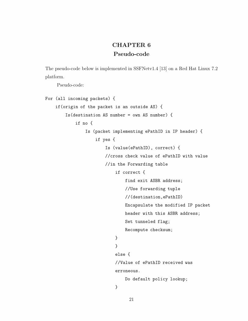
CHAPTER 6
Pseudo-code
The pseudo-code below is implemented in SSFNetv1.4 [13] on a Red Hat Linux 7.2
platform.
Pseudo-code:
For (all incoming packets) {
if(origin of the packet is an outside AS) {
Is(destination AS number = own AS number) {
if no {
Is (packet implementing ePathID in IP header) {
if yes {
Is (value(ePathID), correct) {
//cross check value of ePathID with value
//in the Forwarding table
if correct {
find exit ASBR address;
//Use forwarding tuple
//(destination,ePathID)
Encapsulate the modified IP packet
header with this ASBR address;
Set tunneled flag;
Recompute checksum;
}
}
else {
//Value of ePathID received was
erroneous.
Do default policy lookup;
}
21

22
}
forward the packet;
}
}
else {
//packet doesn’t support ePathID in header
forward the packet;
}
}
}
else {
// Destination AS number is same as own AS number
do normal routing;
}
}
else {
// Origin of the incoming packet is own AS
Is (tunneled flag set){
if yes {
//The packet was coming from an EBGP router via
//encapsulation
Decapsulate the packet;
//Swap the real destination address back in its
//place
Replace incoming ePathID with outgoing ePathID;
Recompute checksum;
forward the packet;
}
}
else {
// tunneled flag is not set

23
Decide on which path to send;
//The above is to be based on policy decisions,
//traffic splitting decisions based on flows etc.
Calculate the sum of AS paths of path chosen = tempID;
Do MD5-Hash + CRC of tempID = ePathID;
find exit ASBR address;
is (tunneling required){
if yes {
//Use forwarding tuple
//(destination,ePathID)
Encapsulate the modified IP packet header with this
ASBR address;
Set tunneled flag;
Recompute checksum;
}
else {
//tunneling is not required
Recompute checksum as ePathID added;
}
}
forward the packet;
}
}
}

CHAPTER 7
Conclusions
The preceding chapters of the thesis provide a detailed look at the connectionless
inter-domain framework that can be used for traffic engineering for a limited set of
goals. These changes can work as proven by once the scheme was implemented on
SSFnet [13]. The code has been implemented in Java on a Red Hat Linux platform
and has been rigourously tested and quite admirably performs the tasks which have
been described in previous chapters.
The simulation results have not yet taken into account the actual control traffic
flow that takes place. Due to this an estimate of the added control traffic due to
implementation code changes can’t be given. This is in tune with the research
requirements of establishing “building blocks” for connectionless TE for the inter-
domain world. However with the “building blocks” in place future research can focus
on how to achieve various TE objectives by composing these building blocks and
investigating how end-to-end applications can leverage the availability of multiple
paths. Moreover the next step is to implement it on Zebra along Emulab [16] which
will lead to quantifying of trade-offs and more rigourously testing the framework.
24

LITERATURE CITED
[1] S.Kalyanaraman et al, “BANANAS: A New Connectionless TrafficEngineering Framework for the Internet,” Submitted for Publication 2002.
[2] D. Awaduche et al, “Overview and Principles of Internet Traffic Engineering,”IETF Internet Draft draft-ietf-tewg-principles-02.txt, Work-in-progress, Jan2002.
[3] A.Elwalid et al,“MATE:MPLS Adaptive Traffic Engineering,”INFOCOMM’01, April 2001.
[4] C.Hopps,“Analysis of an Equal-Cost Multi-Path Algorithm,” IETF RFC2992,2002.
[5] J.Ash,“Traffic Engineering and QoS Methods for IP-,ATM-,&TDM-basedMultiservice Networks,”Internet draft, draft-ietf-tewg-qos-routing-04.txt,Work in progress, October 2001.
[6] D.Awaduche“MPLS and Traffic Engineering in IP Networks,“IEEECommunications Magazine,”Vol.37, No.12, pp. 42-47, 1999.
[7] J.Chen, P.Druschel, D.Subramanian, “An Efficient Multipath ForwardingMethod,” in INFOCOMM’98, March 1998.
[8] S.Kalyanaraman et al. “Connectionless Building Blocks for Intra and InterDomain Traffic Engineering,” submitted for publication in Hotnets, July 2002.
[9] J.Luciani et al “NMBA Next Hop Resolution Protocol (NHRP),” IETF RFC2332, April 1998.
[10] G.Huston, “Commentary on Inter-Domain Routing in the Internet,” IRTFROuting Research Draft draft-iab-bgparch-02, Work in progress, Sept 2001.
[11] J.W.Stewart “BGP4 Inter-Domain Routing in the Internet,” Addison-Wesley,1999.
[12] S.Kalyanaraman et al. “ Load Balancing Traffic in a BGP Environment UsingOn-Line Simulation and Dynamic NAT techniques,”ISMA Winter Workshopon Routing and Topology Analysis, San Diego, December 2001. Available fromhttp://www.caida.org/outreach/isma/0112/talks/shiv/
[13] Scalable Simulation Framework (SSF) Network Models available fromhttp://www.ssfnet.org
25
26
[14] Hema Tahilramani Kaur, “Traffic-Sensitive Routing and Traffic Engineering,”Ph.D. Thesis Rensselaer Polytechnic Institute, Troy, NY 2002
[15] J.Boyle, et al, “Network Hierarchy and Multi-layer Survivability,” InternetDraft, draft-ietf-multi6-multihoming-requirements-02,Work-in-progress,Novemeber 2001.
[16] J.Lepreau, “The Utah Emulab Network Testbed,” http://www.emulab.net/
APPENDIX A
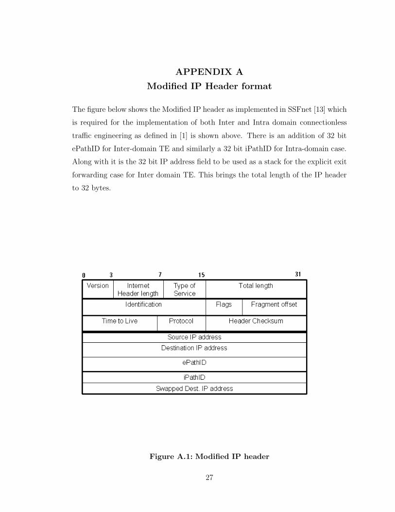
Modified IP Header format
The figure below shows the Modified IP header as implemented in SSFnet [13] which
is required for the implementation of both Inter and Intra domain connectionless
traffic engineering as defined in [1] is shown above. There is an addition of 32 bit
ePathID for Inter-domain TE and similarly a 32 bit iPathID for Intra-domain case.
Along with it is the 32 bit IP address field to be used as a stack for the explicit exit
forwarding case for Inter domain TE. This brings the total length of the IP header
to 32 bytes.
Figure A.1: Modified IP header
27

APPENDIX B
SSFNet
The entire implementation will be online in Testbed lab homepage which can be
accessed via Networks lab webpage at http://networks.ecse.rpi.edu
B.1 Implementation Hurdles and Difficulties
Implementation in SSFnetv1.4 was a very difficult task to do at first with very
less of documentation and support available on account of it being a student version
while the commercial version of the product was being marketed. Moreover there
was no mailing list of it where one could post questions with other users of the
package. However with the help of a number of people in the SSFnet community
implementation difficulties could be overcome.
The full upgrade case could be done with much ease after that due to the fact
that since all routers are upgraded a lot of the debugging can be easily done. All
the time was required in making sure that the right ePathID parameters in the dml
script file are passed to the right entity.
The partial upgrade case is yet in the process of being fully tested and working.
It works under most cases but falters a number of times. The reason for it is partly
because of the timers. If the computations are large then it takes a long time for
the simulation to complete and hence at times it eschews out erroneous data in the
forwarding tables.
28