Embed Size (px)
Citation preview
Schneider Electric - Electrical installation guide 2008
C�
© S
chne
ider
Ele
ctric
- a
ll rig
hts
rese
rved
Chapter CConnection to the LV utility distribution network
Contents Low-voltage utility distribution networks C2
1.1 Low-voltage consumers C2 1.2 Low-voltage distribution networks C10 1.3 The consumer service connection C11 1.4 Quality of supply voltage C15
Tariffs and metering C�6
�
2

Schneider Electric - Electrical installation guide 2008
C - Connecion to the LV public distribution network
C2
© S
chne
ider
Ele
ctric
- a
ll rig
hts
rese
rved
�.� Low-voltage consumers
In Europe, the transition period on the voltage tolerance to “230V/400V + 10% / - 10%” has been extended for another 5 years up to the year 2008.
Low-voltage consumers are, by definition, those consumers whose loads can be satisfactorily supplied from the low-voltage system in their locality.
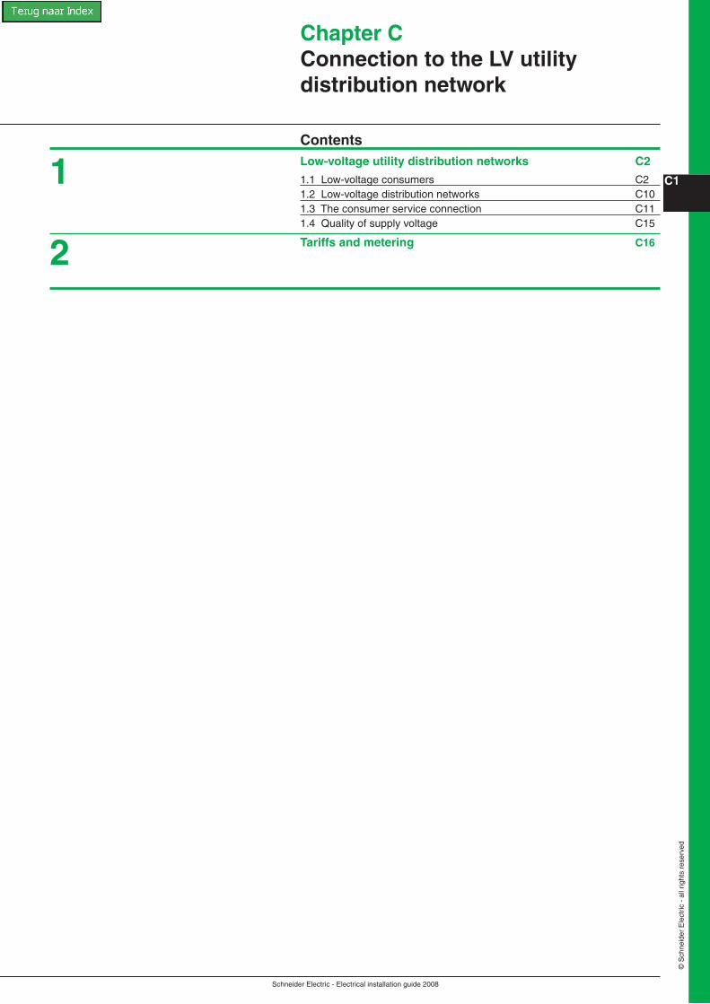
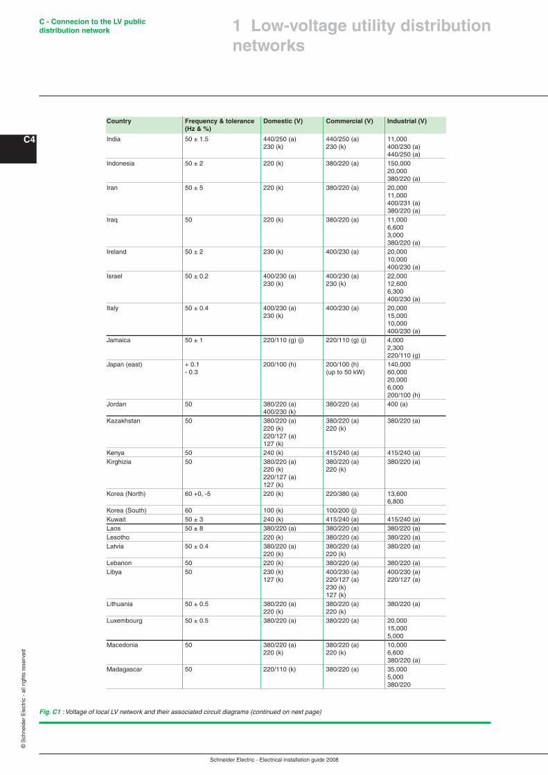
The voltage of the local LV network may be 120/208 V or 240/415 V, i.e. the lower or upper extremes of the most common 3-phase levels in general use, or at some intermediate level, as shown in Figure C�.
An international voltage standard for 3-phase 4-wire LV systems is recommended by the IEC 60038 to be 230/400 V.
Loads up to 250 kVA can be supplied at LV, but power-supply organizations generally propose a MV service at load levels for which their LV networks are marginally adequate.
� Low-voltage utility distribution networks
The most-common LV supplies are within the range 120 V single phase to 240/415 V 3-phase 4-wires.Loads up to 250 kVA can be supplied at LV, but power-supply organizations generally propose a MV service at load levels for which their LV networks are marginally adequate.An international voltage standard for 3-phase 4-wire LV systems is recommended by the IEC 60038 to be 230/400 V
Fig. C1 : Voltage of local LV network and their associated circuit diagrams (continued on next page)
Country Frequency & tolerance Domestic (V) Commercial (V) Industrial (V) (Hz & %) Afghanistan 50 380/220 (a) 380/220 (a) 380/220 (a) 220 (k)
Algeria 50 ± 1.5 220/127 (e) 380/220 (a) 10,000 220 (k) 220/127 (a) 5,500 6,600 380/220 (a)
Angola 50 380/220 (a) 380/220 (a) 380/220 (a) 220 (k)
Antigua and Barbuda 60 240 (k) 400/230 (a) 400/230 (a) 120 (k) 120/208 (a) 120/208 (a)
Argentina 50 ± 2 380/220 (a) 380/220 (a) 220 (k) 220 (k)
Armenia 50 ± 5 380/220 (a) 380/220 (a) 380/220 (a) 220 (k) 220 (k)
Australia 50 ± 0.1 415/240 (a) 415/240 (a) 22,000 240 (k) 440/250 (a) 11,000 440 (m) 6,600 415/240 440/250
Austria 50 ± 0.1 230 (k) 380/230 (a) (b) 5,000 230 (k) 380/220 (a)
Azerbaijan 50 ± 0.1 208/120 (a) 208/120 (a) 240/120 (k) 240/120 (k)
Bahrain 50 ± 0.1 415/240 (a) 415/240 (a) 11,000 240 (k) 240 (k) 415/240 (a) 240 (k)
Bangladesh 50 ± 2 410/220 (a) 410/220 (a) 11,000 220 (k) 410/220 (a)
Barbados 50 ± 6 230/115 (j) 230/115 (j) 230/400 (g) 115 (k) 200/115 (a) 230/155 (j) 220/115 (a)
Belarus 50 380/220 (a) 380/220 (a) 380/220 (a) 220 (k) 220 (k) 220/127 (a) 127 (k)
Belgium 50 ± 5 230 (k) 230 (k) 6,600 230 (a) 230 (a) 10,000 3N, 400 3N, 400 11,000 15,000
Bolivia 50 ± 0.5 230 (k) 400/230 (a) 400/230 (a) 230 (k)
Botswana 50 ± 3 220 (k) 380/220 (a) 380/220 (a)
Brazil 60 220 (k) 220/380 (a) 13,800 127 (k) 127/220 (a) 11,200 220/380 (a) 127/220 (a)
Brunei 50 ± 2 230 230 11,000 68,000
Bulgaria 50 ± 0.1 220 220/240 1,000 690 380

Schneider Electric - Electrical installation guide 2008
C - Connecion to the LV public distribution network
C�
© S
chne
ider
Ele
ctric
- a
ll rig
hts
rese
rved
Fig. C1 : Voltage of local LV network and their associated circuit diagrams (continued on next page)
Cambodia 50 ± 1 220 (k) 220/300 220/380 Cameroon 50 ± 1 220/260 (k) 220/260 (k) 220/380 (a)Canada 60 ± 0.02 120/240 (j) 347/600 (a) 7,200/12,500 480 (f) 347/600 (a) 240 (f) 120/208 120/240 (j) 600 (f) 120/208 (a) 480 (f) 240 (f) Cape Verde 220 220 380/400Chad 50 ± 1 220 (k) 220 (k) 380/220 (a)Chile 50 ± 1 220 (k) 380/220 (a) 380/220 (a)China 50 ± 0.5 220 (k) 380/220 (a) 380/220 (a) 220 (k) 220 (k) Colombia 60 ± 1 120/240 (g) 120/240 (g) 13,200 120 (k) 120 (k) 120/240 (g)Congo 50 220 (k) 240/120 (j) 380/220 (a) 120 (k) Croatia 50 400/230 (a) 400/230 (a) 400/230 (a) 230 (k) 230 (k) Cyprus 50 ± 0.1 240 (k) 415/240 11,000 415/240 Czech Republic 50 ± 1 230 500 400,000 230/400 220,000 110,000 35,000 22,000 10,000 6,000 3,000 Denmark 50 ± 1 400/230 (a) 400/230 (a) 400/230 (a)Djibouti 50 400/230 (a) 400/230 (a)Dominica 50 230 (k) 400/230 (a) 400/230 (a)Egypt 50 ± 0.5 380/220 (a) 380/220 (a) 66,000 220 (k) 220 (k) 33,000 20,000 11,000 6,600 380/220 (a)Estonia 50 ± 1 380/220 (a) 380/220 (a) 380/220 (a) 220 (k) 220 (k) Ethiopia 50 ± 2.5 220 (k) 380/231 (a) 15 000 380/231 (a)Falkland Islands 50 ± 3 230 (k) 415/230 (a) 415/230 (a)Fidji Islands 50 ± 2 415/240 (a) 415/240 (a) 11,000 240 (k) 240 (k) 415/240 (a)Finland 50 ± 0.1 230 (k) 400/230 (a) 690/400 (a) 400/230 (a)France 50 ± 1 400/230 (a) 400/230 20,000 230 (a) 690/400 10,000 590/100 230/400Gambia 50 220 (k) 220/380 380 Georgia 50 ± 0.5 380/220 (a) 380/220 (a) 380/220 (a) 220 (k) 220 (k) Germany 50 ± 0.3 400/230 (a) 400/230 (a) 20,000 230 (k) 230 (k) 10,000 6,000 690/400 400/230 Ghana 50 ± 5 220/240 220/240 415/240 (a)Gibraltar 50 ± 1 415/240 (a) 415/240 (a) 415/240 (a)Greece 50 220 (k) 6,000 22,000 230 380/220 (a) 20,000 15,000 6,600 Granada 50 230 (k) 400/230 (a) 400/230 (a)Hong Kong 50 ± 2 220 (k) 380/220 (a) 11,000 220 (k) 386/220 (a)Hungary 50 ± 5 220 220 220/380 Iceland 50 ± 0.1 230 230/400 230/400
Country Frequency & tolerance Domestic (V) Commercial (V) Industrial (V) (Hz & %)
� Low-voltage utility distribution networks
Schneider Electric - Electrical installation guide 2008
C - Connecion to the LV public distribution network
C�
© S
chne
ider
Ele
ctric
- a
ll rig
hts
rese
rved
Fig. C1 : Voltage of local LV network and their associated circuit diagrams (continued on next page)
India 50 ± 1.5 440/250 (a) 440/250 (a) 11,000 230 (k) 230 (k) 400/230 (a) 440/250 (a)Indonesia 50 ± 2 220 (k) 380/220 (a) 150,000 20,000 380/220 (a)Iran 50 ± 5 220 (k) 380/220 (a) 20,000 11,000 400/231 (a) 380/220 (a)Iraq 50 220 (k) 380/220 (a) 11,000 6,600 3,000 380/220 (a)Ireland 50 ± 2 230 (k) 400/230 (a) 20,000 10,000 400/230 (a)Israel 50 ± 0.2 400/230 (a) 400/230 (a) 22,000 230 (k) 230 (k) 12,600 6,300 400/230 (a)Italy 50 ± 0.4 400/230 (a) 400/230 (a) 20,000 230 (k) 15,000 10,000 400/230 (a)Jamaica 50 ± 1 220/110 (g) (j) 220/110 (g) (j) 4,000 2,300 220/110 (g)Japan (east) + 0.1 200/100 (h) 200/100 (h) 140,000 - 0.3 (up to 50 kW) 60,000 20,000 6,000 200/100 (h)Jordan 50 380/220 (a) 380/220 (a) 400 (a) 400/230 (k) Kazakhstan 50 380/220 (a) 380/220 (a) 380/220 (a) 220 (k) 220 (k) 220/127 (a) 127 (k) Kenya 50 240 (k) 415/240 (a) 415/240 (a)Kirghizia 50 380/220 (a) 380/220 (a) 380/220 (a) 220 (k) 220 (k) 220/127 (a) 127 (k)Korea (North) 60 +0, -5 220 (k) 220/380 (a) 13,600 6,800 Korea (South) 60 100 (k) 100/200 (j) Kuwait 50 ± 3 240 (k) 415/240 (a) 415/240 (a)Laos 50 ± 8 380/220 (a) 380/220 (a) 380/220 (a)Lesotho 220 (k) 380/220 (a) 380/220 (a)Latvia 50 ± 0.4 380/220 (a) 380/220 (a) 380/220 (a) 220 (k) 220 (k) Lebanon 50 220 (k) 380/220 (a) 380/220 (a)Libya 50 230 (k) 400/230 (a) 400/230 (a) 127 (k) 220/127 (a) 220/127 (a) 230 (k) 127 (k)Lithuania 50 ± 0.5 380/220 (a) 380/220 (a) 380/220 (a) 220 (k) 220 (k) Luxembourg 50 ± 0.5 380/220 (a) 380/220 (a) 20,000 15,000 5,000 Macedonia 50 380/220 (a) 380/220 (a) 10,000 220 (k) 220 (k) 6,600 380/220 (a)Madagascar 50 220/110 (k) 380/220 (a) 35,000 5,000 380/220
Country Frequency & tolerance Domestic (V) Commercial (V) Industrial (V) (Hz & %)
� Low-voltage utility distribution networks

Schneider Electric - Electrical installation guide 2008
C - Connecion to the LV public distribution network
C�
© S
chne
ider
Ele
ctric
- a
ll rig
hts
rese
rved
Fig. C1 : Voltage of local LV network and their associated circuit diagrams (continued on next page)
� Low-voltage utility distribution networks
Country Frequency & tolerance Domestic (V) Commercial (V) Industrial (V) (Hz & %)
Malaysia 50 ± 1 240 (k) 415/240 (a) 415/240 (a) 415 (a) Malawi 50 ± 2.5 230 (k) 400 (a) 400 (a) 230 (k)Mali 50 220 (k) 380/220 (a) 380/220 (a) 127 (k) 220/127 (a) 220/127 (a) 220 (k) 127 (k)Malta 50 ± 2 240 (k) 415/240 (a) 415/240 (a)Martinique 50 127 (k) 220/127 (a) 220/127 (a) 127 (k) Mauritania 50 ± 1 230 (k) 400/230 (a) 400/230 (a)Mexico 60 ± 0.2 127/220 (a) 127/220 (a) 13,800 220 (k) 220 (k) 13,200 120 (l) 120 (l) 277/480 (a) 127/220 (b)Moldavia 50 380/220 (a) 380/220 (a) 380/220 (a) 220 (k) 220 (k) 220/127 (a) 127 (k) Morocco 50 ± 5 380/220 (a) 380/220 (a) 225,000 220/110 (a) 150,000 60,000 22,000 20,000 Mozambique 50 380/220 (a) 380/220 (a) 6,000 10,000Nepal 50 ± 1 220 (k) 440/220 (a) 11,000 220 (k) 440/220 (a)Netherlands 50 ± 0.4 230/400 (a) 230/400 (a) 25,000 230 (k) 20,000 12,000 10,000 230/400 New Zealand 50 ± 1.5 400/230 (e) (a) 400/230 (e) (a) 11,000 230 (k) 230 (k) 400/230 (a) 460/230 (e)Niger 50 ± 1 230 (k) 380/220 (a) 15,000 380/220 (a)Nigeria 50 ± 1 230 (k) 400/230 (a) 15,000 220 (k) 380/220 (a) 11,000 400/230 (a) 380/220 (a)Norway 50 ± 2 230/400 230/400 230/400 690 Oman 50 240 (k) 415/240 (a) 415/240 (a) 240 (k) Pakistan 50 230 (k) 400/230 (a) 400/230 (a) 230 (k) Papua New Guinea 50 ± 2 240 (k) 415/240 (a) 22,000 240 (k) 11,000 415/240 (a)Paraguay 50 ± 0.5 220 (k) 380/220 (a) 22,000 220 (k) 380/220 (a)Philippines (Rep of the) 60 ± 0.16 110/220 (j) 13,800 13,800 4,160 4,160 2,400 2,400 110/220 (h) 440 (b) 110/220 (h)Poland 50 ± 0.1 230 (k) 400/230 (a) 1,000 690/400 400/230 (a)Portugal 50 ± 1 380/220 (a) 15,000 15,000 220 (k) 5,000 5,000 380/220 (a) 380/220 (a) 220 (k)Qatar 50 ± 0.1 415/240 (k) 415/240 (a) 11,000 415/240 (a)
Schneider Electric - Electrical installation guide 2008
C - Connecion to the LV public distribution network
C6
© S
chne
ider
Ele
ctric
- a
ll rig
hts
rese
rved
Fig. C1 : Voltage of local LV network and their associated circuit diagrams (continued on next page)
Romania 50 ± 0.5 220 (k) 220/380 (a) 20,000 220/380 (a) 10,000 6,000 220/380 (a) Russia 50 ± 0.2 380/220 (a) 380/220 (a) 380/220 (a) 220 (k) 220 (k) Rwanda 50 ± 1 220 (k) 380/220 (a) 15,000 6,600 380/220 (a)Saint Lucia 50 ± 3 240 (k) 415/240 (a) 11,000 415/240 (a)Samoa 400/230 San Marino 50 ± 1 230/220 380 15,000 380 Saudi Arabia 60 220/127 (a) 220/127 (a) 11,000 380/220 (a) 7,200 380/220 (a)The Solomon Islands 50 ± 2 240 415/240 415/240 Senegal 50 ± 5 220 (a) 380/220 (a) 90,000 127 (k) 220/127 (k) 30,000 6,600 Serbia and Montenegro 50 380/220 (a) 380/220 (a) 10,000 220 (k) 220 (k) 6,600 380/220 (a)Seychelles 50 ± 1 400/230 (a) 400/230 (a) 11,000 400/230 (a)Sierra Leone 50 ± 5 230 (k) 400/230 (a) 11,000 230 (k) 400 Singapore 50 400/230 (a) 400/230 (a) 22,000 230 (k) 6,600 400/230 (a)Slovakia 50 ± 0.5 230 230 230/400 Slovenia 50 ± 0.1 220 (k) 380/220 (a) 10,000 6,600 380/220 (a)Somalia 50 230 (k) 440/220 (j) 440/220 (g) 220 (k) 220/110 (j) 220/110 (g) 110 (k) 230 (k) South Africa 50 ± 2.5 433/250 (a) 11,000 11,000 400/230 (a) 6,600 6,600 380/220 (a) 3,300 3,300 220 (k) 433/250 (a) 500 (b) 400/230 (a) 380/220 (a) 380/220 (a)Spain 50 ± 3 380/220 (a) (e) 380/220 (a) 15,000 220 (k) 220/127 (a) (e) 11,000 220/127 (a) 380/220 (a) 127 (k)Sri Lanka 50 ± 2 230 (k) 400/230 (a) 11,000 230 (k) 400/230 (a)Sudan 50 240 (k) 415/240 (a) 415/240 (a) 240 (k) Swaziland 50 ± 2.5 230 (k) 400/230 (a) 11,000 230 (k) 400/230 (a)Sweden 50 ± 0.5 400/230 (a) 400/230 (a) 6,000 230 (k) 230 (k) 400/230 (a)Switzerland 50 ± 2 400/230 (a) 400/230 (a) 20,000 10,000 3,000 1,000 690/500 Syria 50 220 (k) 380/220 (a) 380/220 (a) 115 (k) 220 (k) 200/115 (a) Tadzhikistan 50 380/220 (a) 380/220 (a) 380/220 (a) 220 (k) 220 (k) 220/127 (a) 127 (k)
Country Frequency & tolerance Domestic (V) Commercial (V) Industrial (V) (Hz & %)
� Low-voltage utility distribution networks

Schneider Electric - Electrical installation guide 2008
C - Connecion to the LV public distribution network
C�
© S
chne
ider
Ele
ctric
- a
ll rig
hts
rese
rved
Fig. C1 : Voltage of local LV network and their associated circuit diagrams (continued on next page)
� Low-voltage utility distribution networks
Country Frequency & tolerance Domestic (V) Commercial (V) Industrial (V) (Hz & %)
Tanzania 50 400/230 (a) 400/230 (a) 11,000 400/230 (a)Thailand 50 220 (k) 380/220 (a) 380/220 (a) 220 (k) Togo 50 220 (k) 380/220 (a) 20,000 5,500 380/220 (a)Tunisia 50 ± 2 380/220 (a) 380/220 (a) 30,000 220 (k) 220 (k) 15,000 10,000 380/220 (a)Turkmenistan 50 380/220 (a) 380/220 (a) 380/220 (a) 220 (k) 220 (k) 220/127 (a) 127 (k) Turkey 50 ± 1 380/220 (a) 380/220 (a) 15,000 6,300 380/220 (a)Uganda + 0.1 240 (k) 415/240 (a) 11,000 415/240 (a)Ukraine + 0.2 / - 1.5 380/220 (a) 380/220 (a) 380/220 (a) 220 (k) 220 (k) 220 (k) United Arab Emirates 50 ± 1 220 (k) 415/240 (a) 6,600 380/220 (a) 415/210 (a) 220 (k) 380/220 (a)United Kingdom 50 ± 1 230 (k) 400/230 (a) 22,000 (except Northern 11,000 Ireland) 6,600 3,300 400/230 (a)United Kingdom 50 ± 0.4 230 (k) 400/230 (a) 400/230 (a) (Including Northern 220 (k) 380/220 (a) 380/220 (a) Ireland) United States of 60 ± 0.06 120/240 (j) 265/460 (a) 14,400 America 120/208 (a) 120/240 (j) 7,200 Charlotte 120/208 (a) 2,400 (North Carolina) 575 (f) 460 (f) 240 (f) 265/460 (a) 120/240 (j) 120/208 (a)United States of 60 ± 0.2 120/240 (j) 480 (f) 13,200 America 120/208 (a) 120/240 (h) 4,800 Detroit (Michigan) 120/208 (a) 4,160 480 (f) 120/240 (h) 120/208 (a)United States of 60 ± 0.2 120/240 (j) 4,800 4,800 America 120/240 (g) 120/240 (g) Los Angeles (California) United States of 60 ± 0.3 120/240 (j) 120/240 (j) 13,200 America 120/208 (a) 120/240 (h) 2,400 Miami (Florida) 120/208 (a) 480/277 (a) 120/240 (h)United States of 60 120/240 (j) 120/240 (j) 12,470 America New York 120/208 (a) 120/208 (a) 4,160 (New York) 240 (f) 277/480 (a) 480 (f) United States of 60 ± 0.03 120/240 (j) 265/460 (a) 13,200 America 120/240 (j) 11,500 Pittsburg 120/208 (a) 2,400 (Pennsylvania) 460 (f) 265/460 (a) 230 (f) 120/208 (a) 460 (f) 230 (f)
Schneider Electric - Electrical installation guide 2008
C - Connecion to the LV public distribution network
C�
© S
chne
ider
Ele
ctric
- a
ll rig
hts
rese
rved
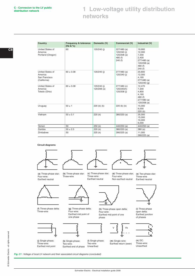
Country Frequency & tolerance Domestic (V) Commercial (V) Industrial (V) (Hz & %)United States of 60 120/240 (j) 227/480 (a) 19,900 America 120/240 (j) 12,000 Portland (Oregon) 120/208 (a) 7,200 480 (f) 2,400 240 (f) 277/480 (a) 120/208 (a) 480 (f) 240 (f)United States of 60 ± 0.08 120/240 (j) 277/480 (a) 20,800 America 120/240 (j) 12,000 San Francisco 4,160 (California) 277/480 (a) 120/240 (g)United States of 60 ± 0.08 120/240 (j) 277/480 (c) 12,470 America 120/208 (a) 120/240(h) 7,200 Toledo (Ohio) 120/208 (j) 4,800 4,160 480 (f) 277/480 (a) 120/208 (a)Uruguay 50 ± 1 220 (b) (k) 220 (b) (k) 15,000 6,000 220 (b) Vietnam 50 ± 0.1 220 (k) 380/220 (a) 35,000 15,000 10,000 6,000 Yemen 50 250 (k) 440/250 (a) 440/250 (a)Zambia 50 ± 2.5 220 (k) 380/220 (a) 380 (a) Zimbabwe 50 225 (k) 390/225 (a) 11,000 390/225 (a)
Fig. C1 : Voltage of local LV network and their associated circuit diagrams (concluded)
(f) Three-phase delta: Three-wire
(g) Three-phase delta; Four-wire: Earthed mid point of one phase
(h) Three-phase open delta; Four-wire: Earthed mid point of one phase
(i) Three-phase open delta: Earthed junction of phases
(j) Single-phase; Three-wire: Earthed mid point
(k) Single-phase; Two-wire: Earthed end of phase
(l) Single-phase; Two-wire Unearthed
(m) Single-wire: Earthed return (swer)
V kV
(b) Three-phase star: Three-wire
Circuit diagrams
(a) Three-phase star; Four-wire: Earthed neutral
(c) Three-phase star; Three-wire: Earthed neutral
(d) Three-phase star; Four-wire: Non-earthed neutral
(e) Two-phase star; Three-wire Earthed neutral
(n) DC: Three-wire: Unearthed
� Low-voltage utility distribution networks
Schneider Electric - Electrical installation guide 2008
C - Connecion to the LV public distribution network
C�
© S
chne
ider
Ele
ctric
- a
ll rig
hts
rese
rved
Residential and commercial consumersThe function of a LV “mains” distributor is to provide service connections (underground cable or overhead line) to a number of consumers along its route.
The current-rating requirements of distributors are estimated from the number of consumers to be connected and an average demand per consumer.
The two principal limiting parameters of a distributor are:b The maximum current which it is capable of carrying indefinitely, andb The maximum length of cable which, when carrying its maximum current, will not exceed the statutory voltage-drop limit
These constraints mean that the magnitude of loads which utilities are willing to connect to their LV distribution mains, is necessarily restricted.
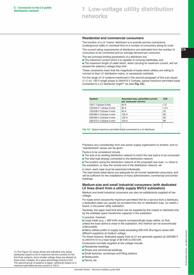
For the range of LV systems mentioned in the second paragraph of this sub-clause (1.1) viz: 120 V single phase to 240/415 V 3-phase, typical maximum permitted loads connected to a LV distributor might(1) be (see Fig. C2):
(1) The Figure C2 values shown are indicative only, being (arbitrarily) based on 60 A maximum service currents for the first three systems, since smaller voltage drops are allowed at these lower voltages, for a given percentage statutory limit. The second group of systems is (again, arbitrarily) based on a maximum permitted service current of 120 A.
Fig. C2 : Typical maximum permitted loads connected to a LV distributor
Practices vary considerably from one power supply organization to another, and no “standardized” values can be given.
Factors to be considered include:b The size of an existing distribution network to which the new load is to be connectedb The total load already connected to the distribution networkb The location along the distribution network of the proposed new load, i.e. close to the substation, or near the remote end of the distribution network, etc
In short, each case must be examined individually.The load levels listed above are adequate for all normal residential consumers, and will be sufficient for the installations of many administrative, commercial and similar buildings.
Medium-size and small industrial consumers (with dedicated LV lines direct from a utility supply MV/LV substation)Medium and small industrial consumers can also be satisfactorily supplied at low-voltage.
For loads which exceed the maximum permitted limit for a service from a distributor, a dedicated cable can usually be provided from the LV distribution fuse- (or switch-) board, in the power utility substation.
Generaly, the upper load limit which can be supplied by this means is restricted only by the available spare transformer capacity in the substation.
In practice, however:b Large loads (e.g. > 300 kVA) require correspondingly large cables, so that, unless the load centre is close to the substation, this method can be economically unfavourableb Many utilities prefer to supply loads exceeding 200 kVA (this figure varies with different suppliers) at medium voltageFor these reasons, dedicated supply lines at LV are generally applied (at 220/380 V to 240/415 V) to a load range of 80 kVA to 250 kVA.Consumers normally supplied at low voltage include:b Residential dwellingsb Shops and commercial buildingsb Small factories, workshops and filling stationsb Restaurantsb Farms, etc
� Low-voltage utility distribution networks
System Assumed max. permitted current kVA per consumer service120 V 1-phase 2-wire 60 A 7.2120/240 V 1-phase 3-wire 60 A 14.4120/208 V 3-phase 4-wire 60 A 22220/380 V 3-phase 4-wire 120 A 80230/400 V 3-phase 4-wire 120 A 83240/415 V 3-phase 4-wire 120 A 86

Schneider Electric - Electrical installation guide 2008
C - Connecion to the LV public distribution network
C�0
© S
chne
ider
Ele
ctric
- a
ll rig
hts
rese
rved
�.2 LV distribution networks
In European countries the standard 3-phase 4-wire distribution voltage level is 230/400 V. Many countries are currently converting their LV systems to the latest IEC standard of 230/400 V nominal (IEC 60038). Mediumto large-sized towns and cities have underground cable distribution systems.MV/LV distribution substations, mutually spaced at approximately 500-600 metres, are typically equipped with:b A 3-or 4-way MV switchboard, often made up of incoming and outgoing load-break switches forming part of a ring main, and one or two MV circuit-breakers or combined fuse/ load-break switches for the transformer circuitsb One or two 1,000 kVA MV/LV transformersb One or two (coupled) 6-or 8-way LV 3-phase 4-wire distribution fuse boards, or moulded-case circuit-breaker boards, control and protect outgoing 4-core distribution cables, generally referred to as “distributors”
The output from a transformer is connected to the LV busbars via a load-break switch, or simply through isolating links.
In densely-loaded areas, a standard size of distributor is laid to form a network, with (generally) one cable along each pavement and 4-way link boxes located in manholes at street corners, where two cables cross.
Recent trends are towards weather-proof cabinets above ground level, either against a wall, or where possible, flush-mounted in the wall.
Links are inserted in such a way that distributors form radial circuits from the substation with open-ended branches (see Fig. C3). Where a link box unites a distributor from one substation with that from a neighbouring substation, the phase links are omitted or replaced by fuses, but the neutral link remains in place.
In cities and large towns, standardized LV distribution cables form a network through link boxes. Some links are removed, so that each (fused) distributor leaving a substation forms a branched open-ended radial system, as shown in Figure C3
Fig. C3 : Showing one of several ways in which a LV distribution network may be arranged for radial branched-distributor operation, by removing (phase) links
4-way link box
HV/LVsubstation
Servicecable
Phase links removed
� Low-voltage utility distribution networks
Schneider Electric - Electrical installation guide 2008
C - Connecion to the LV public distribution network
C��
© S
chne
ider
Ele
ctric
- a
ll rig
hts
rese
rved
In less-densely loaded urban areas a more-economic system of tapered radial distribution is commonly used, in which conductors of reduced size are installed as the distance from a substation increases
Improved methods using insulated twisted conductors to form a pole mounted aerial cable are now standard practice in many countries
� Low-voltage utility distribution networks
This arrangement provides a very flexible system in which a complete substation can be taken out of service, while the area normally supplied from it is fed from link boxes of the surrounding substations.
Moreover, short lengths of distributor (between two link boxes) can be isolated for fault-location and repair.
Where the load density requires it, the substations are more closely spaced, and transformers up to 1,500 kVA are sometimes necessary.
Other forms of urban LV network, based on free-standing LV distribution pillars, placed above ground at strategic points in the network, are widely used in areas of lower load density. This scheme exploits the principle of tapered radial distributors in which the distribution cable conductor size is reduced as the number of consumers downstream diminish with distance from the substation.
In this scheme a number of large-sectioned LV radial feeders from the distribution board in the substation supply the busbars of a distribution pillar, from which smaller distributors supply consumers immediately surrounding the pillar.
Distribution in market towns, villages and rural areas generally has, for many years, been based on bare copper conductors supported on wooden, concrete or steel poles, and supplied from pole-mounted or ground-mounted transformers.
In recent years, LV insulated conductors, twisted to form a two-core or 4-core self supporting cable for overhead use, have been developed, and are considered to be safer and visually more acceptable than bare copper lines.
This is particularly so when the conductors are fixed to walls (e.g. under-eaves wiring) where they are hardly noticeable.
As a matter of interest, similar principles have been applied at higher voltages, and self supporting “bundled” insulated conductors for MV overhead installations are now available for operation at 24 kV.
Where more than one substation supplies a village, arrangements are made at poles on which the LV lines from different substations meet, to interconnect corresponding phases.
North and Central American practice differs fundamentally from that in Europe, in that LV networks are practically nonexistent, and 3-phase supplies to premises in residential areas are rare.
The distribution is effectively carried out at medium voltage in a way, which again differs from standard European practices. The MV system is, in fact, a 3-phase 4-wire system from which single-phase distribution networks (phase and neutral conductors) supply numerous single-phase transformers, the secondary windings of which are centre-tapped to produce 120/240 V single-phase 3-wire supplies. The central conductors provide the LV neutrals, which, together with the MV neutral conductors, are solidly earthed at intervals along their lengths.
Each MV/LV transformer normally supplies one or several premises directly from the transformer position by radial service cable(s) or by overhead line(s).
Many other systems exist in these countries, but the one described appears to be the most common.
Figure C� (next page) shows the main features of the two systems.
�.� The consumer-service connection
In the past, an underground cable service or the wall-mounted insulated conductors from an overhead line service, invariably terminated inside the consumer’s premises, where the cable-end sealing box, the utility fuses (inaccessible to the consumer) and meters were installed.
A more recent trend is (as far as possible) to locate these service components in a weatherproof housing outside the building.
The utility/consumer interface is often at the outgoing terminals of the meter(s) or, in some cases, at the outgoing terminals of the installation main circuit-breaker (depending on local practices) to which connection is made by utility staff, following a satisfactory test and inspection of the installation.
A typical arrangement is shown in Figure C� (next page).
In Europe, each utility-supply distribution substation is able to supply at LV an area corresponding to a radius of approximately 300 metres from the substation.North and Central American systems of distribution consist of a MV network from which numerous (small) MV/LV transformers each supply one or several consumers, by direct service cable (or line) from the transformer location
Service components and metering equipment were formerly installed inside a consumer’s building. The modern tendency is to locate these items outside in a weatherproof cabinet

Schneider Electric - Electrical installation guide 2008
C - Connecion to the LV public distribution network
C�2
© S
chne
ider
Ele
ctric
- a
ll rig
hts
rese
rved
Fig. C4 : Widely-used American and European-type systems
Fig. C5 : Typical service arrangement for TT-earthed systems
N
2
N
N
1
N
3
N
N
2
1 2 3
N
13.8 kV / 2.4-4.16 kV
N3
2
1
21 N
Ph N
}HV (1)
MV (2)
1 ph MV / 230 Vservice transformerto isolated consumer(s)(rural supplies)
For primary voltages > 72.5 kV (see note) primary winding may be:- Delta- Earthed star- Earthed zigzagDepending on the country concerned
Tertiary delta normally (not always) used if the primary winding is not delta
Main 3 ph and neutral MV distributor
(1) 132 kV for example (2) 11 kV for example
Note: At primary voltages greater than 72.5 kV in bulk-supply substations, it is common practice in some European countries to use an earthed-star primary winding and a delta secondary winding. The neutral point on the secondary side is then provided by a zigzag earthing reactor, the star point of which is connected to earth through a resistor. Frequently, the earthing reactor has a secondary winding to provide LV 3-phase supplies for the substation. It is then referredto as an “earthing transformer”.
LV distribution network1 2 3
3 phMV / 230/400 V4-wire distributiontransformer
Resistor replaced by a Petersen coil on O/H line systems in somecountries
2.4 kV / 120-240 V1 ph - 3 wiredistributiontransformer
Each MV/LV transformer shownrepresents many similar units
CB
F
A
M
� Low-voltage utility distribution networks

Schneider Electric - Electrical installation guide 2008
C - Connecion to the LV public distribution network
C��
© S
chne
ider
Ele
ctric
- a
ll rig
hts
rese
rved
A MCCB -moulded case circuit-breaker- which incorporates a sensitive residual-current earth-fault protective feature is mandatory at the origin of any LV installation forming part of a TT earthing system. The reason for this feature and related leakage-current tripping levels are discussed in Clause 3 of Chapter G.
A further reason for this MCCB is that the consumer cannot exceed his (contractual) declared maximum load, since the overload trip setting, which is sealed by the supply authority, will cut off supply above the declared value. Closing and tripping of the MCCB is freely available to the consumer, so that if the MCCB is inadvertently tripped on overload, or due to an appliance fault, supplies can be quickly restored following correction of the anomaly.
In view of the inconvenience to both the meter reader and consumer, the location of meters is nowadays generally outside the premises, either:b In a free-standing pillar-type housing as shown in Figures C6 and C�
b In a space inside a building, but with cable termination and supply authority’s fuses located in a flush-mounted weatherproof cabinet accessible from the public way, as shown in Figure C� next pageb For private residential consumers, the equipment shown in the cabinet in Figure C5 is installed in a weatherproof cabinet mounted vertically on a metal frame in the front garden, or flush-mounted in the boundary wall, and accessible to authorized personnel from the pavement. Figure C� (next page) shows the general arrangement, in which removable fuse links provide the means of isolation
� Low-voltage utility distribution networks
LV consumers are normally supplied according to the TN or TT system, as described in chapters F and G. The installation main circuit-breaker for a TT supply must include a residual current earth-leakage protective device. For a TN service, overcurrent protection by circuit-breaker or switch-fuse is required
Fig. C6 : Typical rural-type installation
In this kind of installation it is often necessary to place the main installation circuit-breaker some distance from the point of utilization, e.g. saw-mills, pumping stations, etc.
CB
M
F
A
Fig. C7 : Semi-urban installations (shopping precincts, etc.)
The main installation CB is located in the consumer’s premises in cases where it is set to trip if the declared kVA load demand is exceeded.
CB
M
F
A
Schneider Electric - Electrical installation guide 2008
C - Connecion to the LV public distribution network
C��
© S
chne
ider
Ele
ctric
- a
ll rig
hts
rese
rved
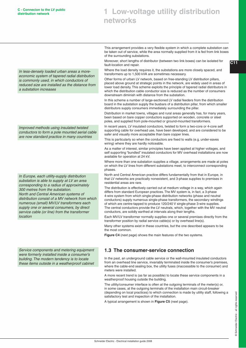
Fig. C8 : Town centre installations
CBM
F
A
The service cable terminates in a flushmounted wall cabinet which contains the isolating fuse links, accessible from the public way. This method is preferred for esthetic reasons, when the consumer can provide a suitable metering and main-switch location.
In the field of electronic metering, techniques have developed which make their use attractive by utilities either for electricity metering and for billing purposes, the liberalisation of the electricity market having increased the needs for more data collection to be returned from the meters. For example electronic metering can also help utilities to understand their customers’ consumption profiles. In the same way, they will be useful for more and more power line communication and radio-frequency applications as well.
In this area, prepayment systems are also more and more employed when economically justified. They are based on the fact that for instance consumers having made their payment at vending stations, generate tokens to pass the information concerning this payment on to the meters. For these systems the key issues are security and inter-operability which seem to have been addressed successfully now. The attractiveness of these systems is due to the fact they not only replace the meters but also the billing systems, the reading of meters and the administration of the revenue collection.
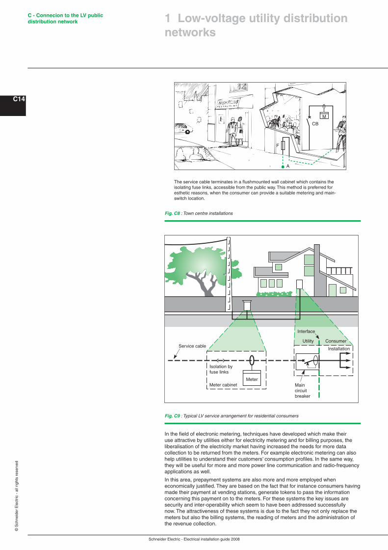
Fig. C9 : Typical LV service arrangement for residential consumers
Isolation by fuse links
Interface
Meter cabinetMeter
Main circuit breaker
InstallationConsumerUtility
Service cable
� Low-voltage utility distribution networks
Schneider Electric - Electrical installation guide 2008
C - Connecion to the LV public distribution network
C��
© S
chne
ider
Ele
ctric
- a
ll rig
hts
rese
rved
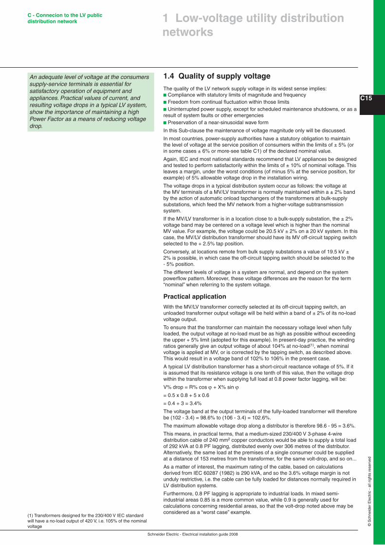
�.� Quality of supply voltage
The quality of the LV network supply voltage in its widest sense implies:b Compliance with statutory limits of magnitude and frequencyb Freedom from continual fluctuation within those limitsb Uninterrupted power supply, except for scheduled maintenance shutdowns, or as a result of system faults or other emergenciesb Preservation of a near-sinusoidal wave form
In this Sub-clause the maintenance of voltage magnitude only will be discussed.
In most countries, power-supply authorities have a statutory obligation to maintain the level of voltage at the service position of consumers within the limits of ± 5% (or in some cases ± 6% or more-see table C1) of the declared nominal value.
Again, IEC and most national standards recommend that LV appliances be designed and tested to perform satisfactorily within the limits of ± 10% of nominal voltage. This leaves a margin, under the worst conditions (of minus 5% at the service position, for example) of 5% allowable voltage drop in the installation wiring.
The voltage drops in a typical distribution system occur as follows: the voltage at the MV terminals of a MV/LV transformer is normally maintained within a ± 2% band by the action of automatic onload tapchangers of the transformers at bulk-supply substations, which feed the MV network from a higher-voltage subtransmission system.
If the MV/LV transformer is in a location close to a bulk-supply substation, the ± 2% voltage band may be centered on a voltage level which is higher than the nominal MV value. For example, the voltage could be 20.5 kV ± 2% on a 20 kV system. In this case, the MV/LV distribution transformer should have its MV off-circuit tapping switch selected to the + 2.5% tap position.
Conversely, at locations remote from bulk supply substations a value of 19.5 kV ± 2% is possible, in which case the off-circuit tapping switch should be selected to the - 5% position.
The different levels of voltage in a system are normal, and depend on the system powerflow pattern. Moreover, these voltage differences are the reason for the term “nominal” when referring to the system voltage.
Practical application
With the MV/LV transformer correctly selected at its off-circuit tapping switch, an unloaded transformer output voltage will be held within a band of ± 2% of its no-load voltage output.
To ensure that the transformer can maintain the necessary voltage level when fully loaded, the output voltage at no-load must be as high as possible without exceeding the upper + 5% limit (adopted for this example). In present-day practice, the winding ratios generally give an output voltage of about 104% at no-load(1), when nominal voltage is applied at MV, or is corrected by the tapping switch, as described above. This would result in a voltage band of 102% to 106% in the present case.
A typical LV distribution transformer has a short-circuit reactance voltage of 5%. If it is assumed that its resistance voltage is one tenth of this value, then the voltage drop within the transformer when supplying full load at 0.8 power factor lagging, will be:
V% drop = R% cos ϕ + X% sin ϕ= 0.5 x 0.8 + 5 x 0.6
= 0.4 + 3 = 3.4%
The voltage band at the output terminals of the fully-loaded transformer will therefore be (102 - 3.4) = 98.6% to (106 - 3.4) = 102.6%.
The maximum allowable voltage drop along a distributor is therefore 98.6 - 95 = 3.6%.
This means, in practical terms, that a medium-sized 230/400 V 3-phase 4-wire distribution cable of 240 mm2 copper conductors would be able to supply a total load of 292 kVA at 0.8 PF lagging, distributed evenly over 306 metres of the distributor. Alternatively, the same load at the premises of a single consumer could be supplied at a distance of 153 metres from the transformer, for the same volt-drop, and so on...
As a matter of interest, the maximum rating of the cable, based on calculations derived from IEC 60287 (1982) is 290 kVA, and so the 3.6% voltage margin is not unduly restrictive, i.e. the cable can be fully loaded for distances normally required in LV distribution systems.
Furthermore, 0.8 PF lagging is appropriate to industrial loads. In mixed semi-industrial areas 0.85 is a more common value, while 0.9 is generally used for calculations concerning residential areas, so that the volt-drop noted above may be considered as a “worst case” example.
� Low-voltage utility distribution networks
An adequate level of voltage at the consumers supply-service terminals is essential for satisfactory operation of equipment and appliances. Practical values of current, and resulting voltage drops in a typical LV system, show the importance of maintaining a high Power Factor as a means of reducing voltage drop.
(1) Transformers designed for the 230/400 V IEC standard will have a no-load output of 420 V, i.e. 105% of the nominal voltage
Schneider Electric - Electrical installation guide 2008
C - Connecion to the LV public distribution network
C16
© S
chne
ider
Ele
ctric
- a
ll rig
hts
rese
rved
(1) Ripple control is a system of signalling in which a voice frequency current (commonly at 175 Hz) is injected into the LV mains at appropriate substations. The signal is injected as coded impulses, and relays which are tuned to the signal frequency and which recognize the particular code will operate to initiate a required function. In this way, up to 960 discrete control signals are available.
2 Tariffs and metering
No attempt will be made in this guide to discuss particular tariffs, since there appears to be as many different tariff structures around the world as there are utilities.
Some tariffs are very complicated in detail but certain elements are basic to all of them and are aimed at encouraging consumers to manage their power consumption in a way which reduces the cost of generation, transmission and distribution.
The two predominant ways in which the cost of supplying power to consumers can be reduced, are:b Reduction of power losses in the generation, transmission and distribution of electrical energy. In principle the lowest losses in a power system are attained when all parts of the system operate at unity power factorb Reduction of the peak power demand, while increasing the demand at low-load periods, thereby exploiting the generating plant more fully, and minimizing plant redundancy
Reduction of losses
Although the ideal condition noted in the first possibility mentioned above cannot be realized in practice, many tariff structures are based partly on kVA demand, as well as on kWh consumed. Since, for a given kW loading, the minimum value of kVA occurs at unity power factor, the consumer can minimize billing costs by taking steps to improve the power factor of the load (as discussed in Chapter L). The kVA demand generally used for tariff purposes is the maximum average kVA demand occurring during each billing period, and is based on average kVA demands, over fixed periods (generally 10, 30 or 60 minute periods) and selecting the highest of these values. The principle is described below in “principle of kVA maximum-demand metering”.
Reduction of peak power demand
The second aim, i.e. that of reducing peak power demands, while increasing demand at low-load periods, has resulted in tariffs which offer substantial reduction in the cost of energy at:b Certain hours during the 24-hour dayb Certain periods of the year
The simplest example is that of a residential consumer with a storage-type water heater (or storage-type space heater, etc.). The meter has two digital registers, one of which operates during the day and the other (switched over by a timing device) operates during the night. A contactor, operated by the same timing device, closes the circuit of the water heater, the consumption of which is then indicated on the register to which the cheaper rate applies. The heater can be switched on and off at any time during the day if required, but will then be metered at the normal rate. Large industrial consumers may have 3 or 4 rates which apply at different periods during a 24-hour interval, and a similar number for different periods of the year. In such schemes the ratio of cost per kWh during a period of peak demand for the year, and that for the lowest-load period of the year, may be as much as 10: 1.
Meters
It will be appreciated that high-quality instruments and devices are necessary to implement this kind of metering, when using classical electro-mechanical equipment. Recent developments in electronic metering and micro-processors, together with remote ripple-control(1) from an utility control centre (to change peak-period timing throughout the year, etc.) are now operational, and facilitate considerably the application of the principles discussed.
In most countries, some tariffs, as noted above, are partly based on kVA demand, in addition to the kWh consumption, during the billing periods (often 3-monthly intervals). The maximum demand registered by the meter to be described, is, in fact, a maximum (i.e. the highest) average kVA demand registered for succeeding periods during the billing interval.
Schneider Electric - Electrical installation guide 2008
C - Connecion to the LV public distribution network
C17
© S
chne
ider
Ele
ctric
- a
ll rig
hts
rese
rved
2 Tariffs and metering
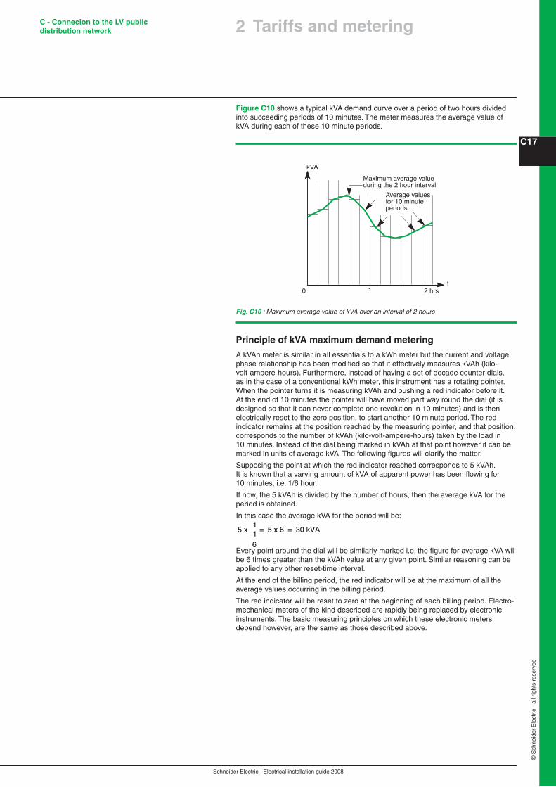
Figure C10 shows a typical kVA demand curve over a period of two hours divided into succeeding periods of 10 minutes. The meter measures the average value of kVA during each of these 10 minute periods.
Fig. C10 : Maximum average value of kVA over an interval of 2 hours
0 1 2 hrst
kVAMaximum average valueduring the 2 hour interval
Average valuesfor 10 minuteperiods
Principle of kVA maximum demand metering
A kVAh meter is similar in all essentials to a kWh meter but the current and voltage phase relationship has been modified so that it effectively measures kVAh (kilo-volt-ampere-hours). Furthermore, instead of having a set of decade counter dials, as in the case of a conventional kWh meter, this instrument has a rotating pointer. When the pointer turns it is measuring kVAh and pushing a red indicator before it. At the end of 10 minutes the pointer will have moved part way round the dial (it is designed so that it can never complete one revolution in 10 minutes) and is then electrically reset to the zero position, to start another 10 minute period. The red indicator remains at the position reached by the measuring pointer, and that position, corresponds to the number of kVAh (kilo-volt-ampere-hours) taken by the load in 10 minutes. Instead of the dial being marked in kVAh at that point however it can be marked in units of average kVA. The following figures will clarify the matter.
Supposing the point at which the red indicator reached corresponds to 5 kVAh. It is known that a varying amount of kVA of apparent power has been flowing for 10 minutes, i.e. 1/6 hour.
If now, the 5 kVAh is divided by the number of hours, then the average kVA for the period is obtained.
In this case the average kVA for the period will be:
5 x 1
= 5 x 6 = 30 kVA16
Every point around the dial will be similarly marked i.e. the figure for average kVA will be 6 times greater than the kVAh value at any given point. Similar reasoning can be applied to any other reset-time interval.
At the end of the billing period, the red indicator will be at the maximum of all the average values occurring in the billing period.
The red indicator will be reset to zero at the beginning of each billing period. Electro-mechanical meters of the kind described are rapidly being replaced by electronic instruments. The basic measuring principles on which these electronic meters depend however, are the same as those described above.


![· LV 01 - LV 02 - 14 - LV LV Of - LV - LV - LV - Skat Foru Out] Profil PM E-Mail Q Pik, Grand? 1272 x) Vorhand ist dran nach passe pa s se. Nach Skatauffiahme:](https://img.pdfslide.us/doc/110x75/5e0d1071f8f59d3156471103/lv-01-lv-02-14-lv-lv-of-lv-lv-lv-skat-foru-out-profil-pm-e-mail-q.jpg)