Embed Size (px)
Citation preview
820
92325_EL 001103
ILPH D-SubSerial Data Converters
Power supplySupply voltageCurrent consumption
With external supply (Pin 9)Supplied on RS 232 signal lines
Connection
RS 232 InterfaceProtectionMax. speed / Max. distanceConnectionStatus indication
RS 422 - RS 485 InterfaceProtectionMax. speed / Max. distanceNo. of connected equipment, max.Line driver managementLine driver termination resistanceLine polarizationConnection
Current loop InterfaceType of current loopMax. speed / Max. distanceNo. of connected equipment, max.ProtectionConnectionStatus indication
Fiber optic InterfaceSize of the fiberWave lengthMax. transmission powerMin. reception sensitivityMax. speed / Max. distance
Connection
Other characteristicsGalvanic isolationOperating temperature rangeDimensions (LxWxH)Weight, approximate
Ser
ial D
ata
Co
nver
ters
These products connect equipment containing RS 232 serialports with other equipment containing serial portswith different communication protocols.The ILPH D-Sub products:
- extend transmission distance of the RS 232 serial portbeyond 15 m (50 ft)
- can be used in "noisy" environments,- perform multidropping (networking) for RS 485 and current loop- act as active or passive current loop,- isolate the two interface systems- protect against overvoltages with fiber optic
(e.g. lightning strikes)
Good EMC performance
The small, rugged metal enclosure ensures that theproducts have very good EMC performance.
Protection against overvoltage and its galvanicisolation make these products safe in very harshindustrial environments.
Host powered by RS 232 signals
An external power supply is not required to operatethe ILPH D-Sub products. The RS 232 signals powerthe interface modules, making them easy andconvenient to use.
Easy configuration and handling
Configuration is performed with Dip-switches. Theconnection cable is secured with cable holders,which also supply shielding continuity.
This new self-powered product range allows a directconnection from an RS 232 serial port to an RS 422-485, 20 mA current loop or plastic fiber optic serialinterface.
The three D-Sub products offer users:
Small rugged metal D-Sub housing Host powered by the RS 232 signals High protection against overvoltages Easy configuration and handling Galvanic isolation (RS 232 / BdC and FO -P) Baud rate up to 115.2 kbits/s
Serial Data Converters
Approvals (contact Entrelec)
Technical characteristic
ILPH D-SubRS 232 / RS 422-485
ILPH D-SubRS 232 / BdC
ILPH D-SubRS 232 / FO-P

821
92325_ER 001103
Derived from RS 232 signal lines or on Pin 9 of the D-Sub5 V DC to 15 V DC max. (Pin 9)
6 to 75 mA (depending on the choosen distance)6 to 12 mA max.
Female 25 pin D-Sub connector
EIA RS 232 / CCITT V 24 V 28no
38.4 kbps - 2 mFemale 25 pin D-Sub connector
Plastic fiber optic1000 micro m - 0.23 dB/km
600 nm- 5.1 dBm at 25°C- 39 dBm at 25°C
38.4 kBps - 155 m max. external supply38.4 kBps - 45 m max. host powered RS 232
HP versatile link (Duplex) HFBR
total-5°C to +65°C
3.03 x 0.75 x 1.65 IN (77x 19 x 42 mm )2.3 oz (65 g)
Derived from RS 232 signal lines or on Pin 9 of the D-Sub5 V DC to 15 V DC max. (Pin 9)
11 mA on TX/RX and DTR signalFemale 25 pin D-Sub connector
EIA RS 232 / CCITT V24 V28no
19.2 kbps - 2mFemale 25 pin D-Sub connector
RX and TX LEDs if power supply on pin 9 connected
Passive 20 mA current loop acitve with external powersupply on 2.1 mm jack connector
19200 bits/s / 1000 m, 9 km at 300 bit/s3 with half duplex and external power supply
25 V Transil1
5 x 16 AWG (5 x 1 mm²) pin screw terminalsRX and TX LEDs if power supply on pin 9 connected
RS 232 / BdC: 2.5 kV rms / 1 min-5°C to +65°C
3.03 x 0.83 x 1.65 IN (77 x 21 x 42 mm) 2.6 oz (75 g)
Derived from RS 232 signal lines or on Pin 9 of the D-Sub5 V DC to 15 V DC max. (Pin 9)
80 mA (max. 32 connected equip., 2 line terminations)4.3 mA with only 1 RS 422 receiver or RS 485 products
Female 25 pin D-Sub connector
EIA RS 232 / CCITT V24 V28no
38.4 kbps - 2 mFemale 25 pin D-Sub connector
RX and TX LEDs if power supply on pin 9 connected
EIA RS 485 and compatible with EIA RS 422/ CCITT V11Transil1 diode on RX and TX
112 kbit/s 1200 m with 50 pF/m cable32 if external power supply connected to pin 9
With RTS/CTS signal120 ohm
if external power supply connected on pin 95 x 16 AWG (5 x 1 mm²) pin screw terminals
no-5°C to +65°C
2.62 x 0.75 x 1.63 IN (66.5 x 19 x 41.5 mm)3.4 oz ( 95 g)
ILPHD-Sub RS 232 / RS 422 - RS 485 0 084 204 25
ILPHD-Sub RS 232 BdC 0 084 203 24
ILPHD-Sub RS 232 / FO-P 0 084 205 26
Connection between an RS 232 serialport and a current loop serial interface
Extends the transmission distance of theRS 232 output beyond 15 m (50 ft)Acts as active or passive current loopAllows use in "noisy" environmentsPerforms multidropping (networking)Isolates the two interfaces
Connection between an RS 232 serialport and a plastic fiber optic serialinterface
Extends the transmission distance of theRS 232 output beyond 15 m (50 ft)Allows use in "noisy" environmentsIsolates the two interface systemsProtects against overvoltages(e.g. lightning strikes)
Connection between an RS 232 serialport and an RS 422-485 serial interface
Extends the transmission distance of theRS 232 output beyond 15 m (50 ft)Allows use in "noisy" environmentsPerforms multidropping (networking)
Type P/N Type P/NType P/N
ILPH D-SUBRS 232 / BdC
ILPH D-SUBRS 232 / FO-P
ILPH D-SUBRS 232 / RS 422-485
Spacing 21 mm .826“ Spacing 19 mm .748“Spacing 19 mm .748“
1 Transil™ SGS Thomson Microelectronics, Overvoltage protection diode

822
ND11001
ILPHRS 232 / RS 422 - RS 485
ILPHRS 232 / RS 422 - RS 485
001103
ILPH RS 232 / RS 422 - RS 485
0084 231.170084 233.11
ILPH RS 232 / RS 422 - RS 485
0084 333.150084 334.16
"ILPH"
Serial data converters
Series 11 000DIN 1 - 3
"ILPH"
Approvals (Contact Entrelec)
Part numbers Type P/N Type P/N
Characteristics
Accessories, marking, wire size : see Accessories section.
(3 way isolated)
Connection between an RS-232 serial interface and anRS-422 - RS-485 serial interface. Two models : with or withoutisolation. Features :- to extend transmission distance beyond the 15 m limit of the
RS-232 serial interface- use in "noisy" environments- to isolate the two interface systems (isolated model only)- to perform multidropping
Data flow optically isolated on the isolated model.
Detailed wiring diagrams available upon request. Contact us.
Spacing 22.5 mm .886"
POWER SUPPLYVoltageProtectionRated currentConnection
RS 232 INTERFACEInput / Output protectionMax. speed / Max. distanceConnection
CURRENT LOOP LINKTransmission / ReceptionLogic typeMax. speed / Max. distanceConnection
RS 422 - RS 485 INTERFACEInput / Output protectionMax. speed / Max. distanceRS 485 high impedance controllingAdaptation resistorLine pull up and pull down resistorConnectionTerminating resistor
OTHER CHARACTERISTICSGalvanic isolation* Isolated model only
Status indicatorVoltage indicatorTraffic indicator
8.5 to 28 V DCReverse polarity
Less than 100 mACompression clamp terminals
EIA RS 232 C / CCITT V 24 / V 28Overvoltage
38400 Baud / 15 mCompression clamp terminals
EIA RS 485 and compatible EIA RS 422/ CCITT V11Overvoltage
38400 Baud / 1200 mBy external signal (RTS of the RS 232) or by internal control
IntegratedIntegrated
Compression clamp terminals120 or 220 Ω
Power supply / RS 422 - RS 485 : 500 V DC*RS 232 / RS 422 - RS 485 : 500 V DC*
1 yellow LED3 green LEDs (RxD, TxD, CTRL IN)
Black bodyNon isolated modelIsolated model
center of rail
Interface between an RS-232 serial link and an RS-422 orRS-485 serial link with 500 VDC isolation. Features :- to extend transmission distance beyond the 15 m limit of the
RS-232 serial link,- to cross "noisy" environments,- to isolate the two interface systems,- to perform multidropping (network),
Black bodyIsolated model, DC supply voltageIsolated model, AC supply voltage
20,4 to 57,6 V DC 95 to 265 V AC (50/60 Hz)Reverse polarity
Less than 100 mACompression clamp terminals
EIA/TIA RS 232 E / UIT-T V 24 / V 28Overvoltage
20000 Baud / 15 mCompression clamp terminals
EIA RS 485 and compatible EIA RS 422-A / UIT-T V11Overvoltage
20000 Baud / 1200 mBy external signal (RTS of the RS 232) or by internal control
IntegratedIntegrated
Compression clamp terminals120 Ω
Power supply / RS 422 - RS 485 : 1,5 kV ACPower supply / RS 232 : 1,5 kV ACRS 232 / RS 422 - RS 485 : 1,5 kV AC
1 yellow LED3 green LEDs (RxD, TxD, CTRL IN)
Spacing 22.5 mm .886"
823
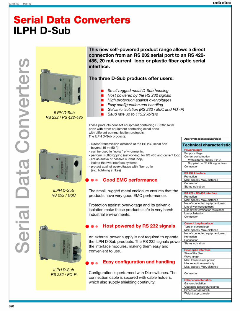
ILPHRS 232 / BdC
ILPHBdC / RS 422 - RS 485
ND11002 001103
ILPH RS 232 / BdC
0084 202.23
ILPH BdC / RS 422-RS 485
0084 232.10
Serial data converters
Series 11 000DIN 1 - 3
"ILPH"
Approvals (Contact Entrelec)
Part numbers Type P/N Type P/N
Characteristics
Accessories, marking, wire size : see Accessories section.
Connection between an RS 232 serial interface and a CL(current loop) serial interface. Transmission / Reception inactive or passive mode. Ensures isolation. Features:- to extend transmission distance beyond the 15 m limit of the
RS 232 serial interface- use in "noisy" environments- to isolate the two interface systems- to perform multidropping
Data flow optically isolated.
Detailed wiring diagram available upon request. Contact us.
Spacing 22.5 mm .886" Spacing 22.5 mm .886"
Connection between a CL (current loop) serial interface and anRS 422 or RS 485 serial interface. Transmission / Reception inactive or passive mode. Ensures isolation. Features :- to isolate the two interface systems- to perform multidropping
Data flow optically isolated.
Detailed wiring diagram available upon request. Contact us.
POWER SUPPLYVoltageProtectionRated currentConnection
RS 232 INTERFACEProtectionMax. speed / Max. distanceConnection
CURRENT LOOP LINKTransmission / ReceptionLogic typeMax. speed / Max. distanceConnection
RS 422 - RS 485 INTERFACEInput / Output protectionMax. speed / Max. distanceRS 485 high impedance controllingAdaptating resistorLine pull up and pull down resistorConnectionTerminating resistor
OTHER CHARACTERISTICSGalvanic isolation
Status indicatorVoltage indicatorTraffic indicator
21.6 to 26.4 V DCReverse polarity
120 mA max.Compression clamp terminals
EIA RS 232 C / CCITT V 24 / V 28Overvoltage
38400 Baud / 15 mCompression clamp terminals
Active or passive mode configurationSelection 1 = 20 mA or 0 = 20 mA
38400 Baud / 1200 mCompression clamp terminals
Power supply / BdC :500 V DC (Active) 2000 V DC (Passive)RS 232 / BdC : 500 V DC (Active) 2000 V DC (Passive)
1 yellow LED2 green LEDs (RxD, TxD)
Black bodyIsolated model
Black bodyIsolated model
21.6 to 26.4 V DCReverse polarity
120 mA max.Compression clamp terminals
Active or passive mode configurationSelection 1 = 20 mA or 0 = 20 mA
38400 Baud / 1200 mCompression clamp terminals
EIA RS 485 and compatible EIA RS 422/ CCITT V11Overvoltage
38400 Baud / 1200 mBy internal treatment
Jumper selectedJumper selected
Compression clamp terminals120 or 220 Ω
Power supply / RS 422 - RS 485 : 500 V DCBdC / RS 422 - RS 485 : 500 V DC
1 yellow LED2 green LEDs (RxD, TxD)
"ILPH"
center of rail

824
ILPH RS 232/RS 232 24/48DC 0084 234.12
ILPHRS 232/RS 232
"ILPH""ILPH"
ND11004
ILPH RS 232/RS 232 115/230AC 0084 244.24
24/48 VDC 115/230 VAC
ILPH RS 422 - RS 485 / RS 422 - RS 485
0084 212.14
ILPHRS 422 - RS 485 / RS 422 - RS 485
001103
Galvanic isolator between RS 232 serial interface and anotherRS 232 serial interface.Ensures triple isolation (2.5 kVAC) between the 2 serialinterfaces and between each serial interface and power supply.This interface protects the two systems.Large DC power supply range between 20.4 VDC to57.6 VDC (24 /48 VDC)Large AC power supply range between 95 to265 VAC (115 / 230 VAC)
Serial data isolator
Series 11 000DIN 1 - 3
POWER SUPPLYVoltage
Overvoltage protection (1,2/50µs wave)Protection against reverse polarity
Maximum supply powerSupply current
ConnectionVoltage indicatorGalvanic isolationBetween supply and channel 1Between supply and channel 2Between channel 1 and channel 2
RS232 Interface (1 and 2 channels)Standard
Maximum binary data ratePropagation time high state (TPLH)
low state (TPHL)Max. cable lengthMaximum capacity allowed by emittersConnectionTraffic indicationOvervoltage protection(1,2/50µs wave)
OTHER CHARACTERISTICSMTBF according to RDF93 CNET softwareEM compatibility
Electrostatic dischargeRadiated electromagnetic fieldRadiated RFIConducted RFI
Operating temperatureOperating humidityStorage temperature
20.4 to 57.6 VDC 95 to 264 VAC (50Hz et 60Hz)(~115 Vac -15% to ~230 Vac+15%)
8 kV 8 kVdiodes
3.15 W 3,15 W24V DC Supply current < 155 mA48V DC Supply current < 77 mA
Removable compression clamp terminal Removable compression clamp terminal 1 yellow LED 1 yellow LED
2.5 kV AC2.5 kV AC2.5 kV AC
EIA/TIA 232E (RS232 new revision)UIT-T V28 and UIT-T V24
20 kbits/s (64 kbits/s depending on cable)8 µs max. (48 µs typ.)8 µs max. (48 µs typ.)
15 m max.2500 pF
Compression clamp terminals4 x green LED (RxD,RxC/D, TxD,TxC/D)
8 kV
35000 h to 40°C
8 kV in air (IEC 1000-4-2 level 3, like IEC 801-2)10 V/m (IEC 1000-4-3 level 3, like IEC 801-3)
EN 55022 Class B1 kV (IEC 1000-4-4 level 3, like IEC 801-4)
0 to 40°C5 to 95 %
-25 to +80°C
Part numbers
Accessories, marking, wire size : see related sections.
Approvals (Contact Entrelec)
Type P/N Type P/N
Characteristics
Black body
Black body
Connection between an RS 422 - RS 485 serial interface and anRS 422 - RS 485 serial interface. Ensures isolation. Features:- to repeat and amplify the signal, RS 422 - RS 485- to extend transmission up to 1200 m- to isolate the two interface systems
Spacing 22.5 mm .886"
Black bodyIsolated model
20.4 to 28.8 V DC
Reverse polarity
120 mA max.
Compression clamp terminals1 yellow LED
Power supply / (RS 422 - RS 485)2 : 500 V DC(RS 422 RS 485)1 / (RS 422 - RS 485)2 : 500 V DC
EIA RS 485 and compatible EIA RS 422/ CCITT V11
Compression clamp terminals2 green LEDs (RxD, TxD)
yes
isolated
Spacing 22.5 mm .886"
(3 way isolated)

825
ILPHRS 232/BdC 24/AL24
"ILPH""ILPH"
ILPHRS 232/BdC 24/AL230
ND11005
ILPH RS 232/BdC 24/AL24 0084 235.13 ILPH RS 232/BdC 24/AL230 0084 245.25
001103
Interface between RS 232 serial interface and a currentloop (0/4-20 mA) serial interface.Ensures triple isolation (2.5 k VAC) between the 2 serialinterfaces and each serial interface and power supply.24 V DC current loop power supply, Active/Passive functionmode independently selectable on each Current loop channel.Features :- to protect the two interface systems- to extend transmission distance of the RS 232
beyond the 15 m to 1200 m- to cross a "noisy" industrial environnement- large power supply range from 20.4 to 57.6 V DC.
Serial data converter
Series 11 000DIN 1 - 3
Interface between RS 232 serial interface and a currentloop (0/4-20 mA) serial interface.Ensures triple isolation (2.5 kV AC) between the 2 serialinterfaces and each serial interfaces and power supply.24 V DC current loop power supply, Active/Passive functionmode independently selectable on each Current loop channel.Features :- to protect the two interface systems- to extand transmission distance of the RS 232
beyond the 15 m to 1200 m- to cross a "noisy" industrial environnement- large power supply range from 95 to 264 V AC.
POWER SUPPLYVoltage
Overvoltage protections (1,2/50µs wave)Protection against reverse polarity
Maximum supply powerSupply current
ConnectionsVoltage indicatorGalvanic isolationBetween supply and channel 1Between supply and channel 2Between channel 1 and channel 2
RS232 InterfaceStandardMaximum binary data rateMaximum capacity allowed by emittersConnectionTraffic indication
Current loop interfaceEmission receptionMaximum binary data rateLogical typeConnection
OTHER CHARACTERISTICSMTBF according to RDF93 CNET softwareEM compatibility
Electrostatic dischargeRadiated electromagnetic fieldRadiated RFIConducted RFI
Operating temperatureOperating humidityStorage temperature
20.4 to 57.6 V DC 95 to 264 V AC (50 Hz and 60 Hz)(~115 V AC -15% to ~230 V AC +15%)
8 kV 8 kVdiodes
3 W 3 W24 V DC Supply Ic < 110 mA 115 V AC Supply Ic < 40 mA48 V DC Supply Ic < 55 mA 230 V AC Supply Ic < 26 mARemovable screw terminal Removable screw terminal
1 yellow LED 1 yellow LED
2.5 kV AC2.5 kV AC2.5 kV AC
EIA/TIA 232E (RS 232 new revision) UIT-T V28 and UIT-T V2420 kbits/s (64 kbits/s depending on cable)
2500 pFCompression clamp terminals
2 x green LED (RxD, TxD)
Active or passive mode independently switch selectable20 kbits/s (64 kbits/s depending on cable)1=20 mA or 0=20 mA switch selectable
Compression clamp terminals
35000 h at 40°C
8 kV in air (IEC 1000-4-2 level 3, like IEC 801-2)10 V/m (IEC 1000-4-3 level 3, like IEC 801-3)
EN 55022 Class B1 kV (IEC 1000-4-4 level 3, like IEC 801-4)
0 to +40°C5 to 95 %
-25 to +80°C
Black body
Part numbers
Accessories, marking, wire size : see related sections.
Approvals (Contact Entrelec)
Type P/N Type P/N
Characteristics
Black body
(3 way isolated) (3 way isolated)

826
A B C
M L K
J H G
D E F
RS 232 / FO
RxDDV
TxD
OV
M
L
K
E
G
F D A B C
←→
~-
~+
CSO60012 000816
Technical data
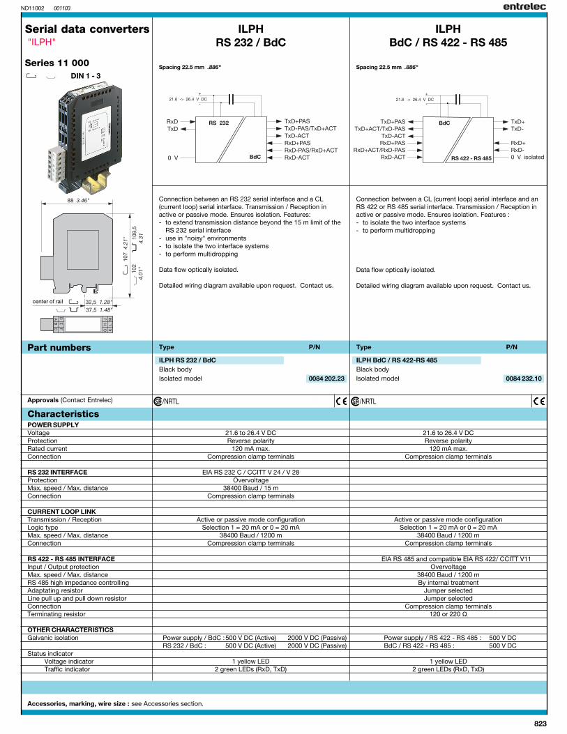
Serial data convertersFiber optic"ILPH"
ILPH RS 232 / FO
Spacing 22,5 mm .886"
3 way galvanic isolated converter for RS 232 to fiber optic serial linkplastic (P) or glass (S).
3-way galvanic isolation between power supply and Input/outputBaud rate up to 115,2 kbit/sAvailable for plastic or glass fibersTransmission distance up to 4 km (glass)Usable in "very noisy" environments20...42 V AC/DC and 95...264 V AC power supplyCE marked
Type: P/N:
Approvals:
Part numbersILPH RS 232 / FO -S24...42 V AC/DC power supply 0 084 236 14110...240 V AC power supply 0 084 237 15ILPH RS 232 / FO -P24...42 V AC/DC power supply 0 084 238 26110...240 V AC power supply 0 084 239 27
Power suppliesSupply voltage 24...42 V AC/DC 110...240 V AC (50/60 Hz)Voltage tolerance -15% ... +10% -15% ... +10%Power, approximately 3 W 3 VAConnections Omniconnect pluggable connector RS 232 Interface 1 CCITT V.24/DIN 66020- CCITT V.28 DIN 66259-EIA 232 EProtection Integrated (transil 8 kV 1,2/50 µs)Max. speed / Max. distance Max. 115,2 kbits/s / max. 15 m / 2500 pFConnections Omniconnect pluggable connectorFiber optic interface 2 DIN VDE 0888-1Type of fiber / Connections Multimode fiber
Glass: ST connector / Plastic: FSMA connectorWavelength Glass: 820 mm / Plastic: 655 mmMax. transmission power Glass: 50/125 µm: -18,4 db/m
Glass: 62,5/125 µm: -14 db/mPlastic: 980/1000 µm: -8 db/m
Max. reception power Glass: -28 db/m / Plastic: -20 db/mMax. speed Max. 115,2 kbits/sMax. distance Glass: 50/125 µm: 3 km
Glass: 62,5/125 µm: 4 kmPlastic: 980/1000 µm: 40 m
Status indicationPower supply / Data exchange 1 green LED / 2 green LEDs (RxD, TxD)EMC behaviorECD EN 61000-4-2 Level 3 6/8 kVRF Field EN 61000-4-3 Level 3 10 V/mBurst EN 61000-4-4 Level 3 1 kVElectromagnetic compatibility EN 55022 Class BOther characteristicsGalvanic isolation input / power supply / output 2,5 kVOperating temperature -20°C ... +60°CStorage temperature -40°C ... +85°CMounting Onto DIN Rail (EN 50002)Connections 14 AWG (2,5 mm2) / fine stranded, 12 AWG (4 mm2)/rigidDimensions (LxWxH) 105 x 22.5 x 112 mm (4.13 x .89 x 4.41")Weight 150 g (5.3 oz.)
U: power supply, green LED
Plug-in omniconnect terminals
Transmit fiber
Receive fiber
Shielding
FOReceiving
FOSending
Shielding

827
ILPH RS 485 / FO
A B C
M L K
J H G
D E F
RS 485 / FO
←
OVD -
D +
OV
Spacing 22,5 mm .886"
←
CSO60013 000816
Baud rate bits/s
Polarization
Serial data convertersFiber optic"ILPH"
Part numbers
Approvals:
~+~-
←
3-way galvanic isolated converter for RS 485 (1 pair) to fiber opticserial link plastic (P) or glass (S)
3-way galvanic isolation between power supply and input/outputBaud rate up to 1.5 Mbit/sAvailable for plastic or glass fibersTransmission distance up to 4 km (glass)Usable in "very noisy" environments20...42 V AC/DC and 95...264 V AC power supplyCE marked
Power suppliesSupply voltages 24...42 V AC/DC 110...240 V AC (50/60 Hz)Voltage tolerance -15% ... +10% -15% ... +10%Power, approximately 3 W 3 VAConnections Omniconnect Pluggable connectorRS 422 - 485 interface 1 ISO / IEC 8482 / DIN 66 259-4; EIA 485Protection Integrated (8 kV 1.2/50µs)Max. speed / max. distance Max. 1.5 Mbits/s / max. 1200 m (38.4 kbit/s)Connections Omniconnect Pluggable connectorFiber optic interface 2 DIN VDE 088-1Type of fiber / Connections Multimode fiber
Glass: ST connector / Plastic: FSMA connectorWavelength Glass: 820 mm / Plastic: 655 mmMax. transmission power Glass: 50/125 µm: -18,4 db/m
Glass: 62,5/125 µm: -14 db/mPlastic: 980/1000 µm: -8 db/m
Max. reception power Glass: -28 db/m / Plastic: -20 db/mMax. speed Max. 1.5 Mbit/sMax. distance Glass: 50/125 µm: 3 km
Glass: 62,5/125 µm: 4 kmPlastic: 980/1000 µm: 40 m
Status indicationPower supply / Data exchange 1 green LED / 2 green LEDs (RxD, TxD)EMC behaviorESD EN 61000-4-2 Level 3 6/8 kVRF field EN 61000-4-3 Level 310 V/mBurst EN 61000-4-4 Level 3 1 kVElectromagnetic compatibility EN 55022 Class BOther characteristicsGalvanic isolation Input / Power supply / Output 2.5 kVOperating temperature -20°C ... +60°CStorage temperature -40°C ... +85°CMounting Onto DIN RailConnections 14 AWG (2,5 mm2) / fine stranded, 12 AWG (4 mm2)/rigidDimensions (LxWxH) 105 x 22,5 x 112 mm (4.13 x .89 x 4.41" )Weight 150 g (5.3 oz.)
Technical data
ILPH RS 485 / FO -S24...42 V AC/DC Power supply 0 084 246 26110...240 V AC Power supply 0 084 247 27ILPH RS 485 / FO -P24...42 V AC/DC Power supply 0 084 248 00110...240 V AC Power supply 0 084 239 01
Type: P/N:
Baud rate:SW1 DIP switch configuration
Transmit fiber
Receive fiber
U: Power supply, green LED
Pluggable omniconnect terminals
Shielding
LegendInOut
FOSending
FOReceiving
Shielding

828
CS060002 000816
Product overviewProduct overview
RS 232 - EIA-232 / V.24 / V.28• Point-to-point connection• Max. 15 m transmission distance• Well known worldwide• Low baud rate (up to 19.2 kbit/s)• Full-duplex
RS 485 - ISO/IEC/EIA-485• Multi-point connection up to 32 units• Differential voltage transmission• Half-duplex on 1 pair• Full-duplex on 2 pairs
Serial link1
Serial link 2
RS 232 RS 232 RS 232 RS 422-485 RS 485 BdCD-Sub DIN Rail DIN Rail DIN Rail DIN Rail DIN Rail
with isolation with isolation with isolation with isolation with isolation
self-powered 24...42 V AC/DC 24...42 V AC/DC0 084 205 26 0 084 238 26 0 084 248 00
110...240 V AC 110...240 V AC0 084 239 27 0 084 249 01
24...42 V AC/DC 24...42 V AC/DC0 084 236 14 0 084 246 26
110...240 V AC 110...240 V AC0 084 237 15 0 084 247 27
Fiber optic interface• Point-to-point connection• Full-duplex• From 40m up to 4km
transmission distanceaccording to fiber optic material(plastic/glass) andwavelength usedup to 10 Mb/s
• Excellent EMC characteristics
FO-P
FO-S
How fiber optics work ?
The basic principle of wave propagation into a fiber optic is based on the total reflection effect. This property is very useful andthe light is permanently reflected between the fiber core and fiber housing and so guided along the fiber.
Various types of fiber optics:
In addition to the material used for the fiber optic itself (plastic or glass), the fabrication mode is also very important to assure a qualify fiber. Two otherparameters must also be taken into account:
• Unimode or monomode fiber• Multimode fiber
A monomode fiber has a very small diameter, allowing only the fundamental wave to come through. The advantage of this fiber is that pulse deformationand power loss are very low, but the high price is a drawback.
Multimode fibers allow the propagation of various waves (fundamental and others) into the fiber core (relatively large diameter). They are divided into twogroups:
• Step index fibers
In these fibers, the light beams are totally reflected at the interface ofthe core and the fiber housing, but as some waves are more oftenreflected then others, the output pulse has a bigger deformation. Sucha fiber is not really well suited for industrial application or only forshort distances. This type of fiber also exists in plastic material with adiameter of 980/100 µm.
• Gradient fibers
In the gradient fiber, the index of refraction decreases slightly and continuouslyfrom the fiber axial core to the fiber housing. The light beamsare then no more diffused in "zig-zag" fashion but in wave form. The bigadvantage of such a fiber is faster propagation of the light into thethe fiber and then when the index is appropriate, the output pulseis not modified. As the power attenuation is very small,these fibers are very well suited for long distances up to 3 km. Thecommonly used fibers have a diameter of 50/125 µm and 62.5/125 µm.

829
NOTES