Embed Size (px)
Citation preview

White Paper
Copyright © 2014, Juniper Networks, Inc. 1
CONNECTING PHYSICAL AND VIRTUAL WORLDS WITH VMWARE NSX AND JUNIPER PLATFORMS A Joint Juniper Networks-VMware White Paper
2 Copyright © 2014, Juniper Networks, Inc.
Connecting Physical and Virtual Worlds with VMware NSX and Juniper Platforms
Table of ContentsExecutive Summary . . . . . . . . . . . . . . . . . . . . . . . . . . . . . . . . . . . . . . . . . . . . . . . . . . . . . . . . . . . . . . . . . . . . . . . . . . . . . . . . . . . . . . . . . . . . . .3
Introduction: Network Virtualization with NSX . . . . . . . . . . . . . . . . . . . . . . . . . . . . . . . . . . . . . . . . . . . . . . . . . . . . . . . . . . . . . . . . . . . . . .3
Control Plane . . . . . . . . . . . . . . . . . . . . . . . . . . . . . . . . . . . . . . . . . . . . . . . . . . . . . . . . . . . . . . . . . . . . . . . . . . . . . . . . . . . . . . . . . . . . . . . . . 5
Data Plane . . . . . . . . . . . . . . . . . . . . . . . . . . . . . . . . . . . . . . . . . . . . . . . . . . . . . . . . . . . . . . . . . . . . . . . . . . . . . . . . . . . . . . . . . . . . . . . . . . . 5
Extending Virtual Networks to Physical Space with Layer 2 Gateways . . . . . . . . . . . . . . . . . . . . . . . . . . . . . . . . . . . . . . . . . . . . . . . 5
Use Cases . . . . . . . . . . . . . . . . . . . . . . . . . . . . . . . . . . . . . . . . . . . . . . . . . . . . . . . . . . . . . . . . . . . . . . . . . . . . . . . . . . . . . . . . . . . . . . . . . . . . 6
Physical Tier . . . . . . . . . . . . . . . . . . . . . . . . . . . . . . . . . . . . . . . . . . . . . . . . . . . . . . . . . . . . . . . . . . . . . . . . . . . . . . . . . . . . . . . . . . . . . . . . 6
Physical to Virtual (P2V) Migration . . . . . . . . . . . . . . . . . . . . . . . . . . . . . . . . . . . . . . . . . . . . . . . . . . . . . . . . . . . . . . . . . . . . . . . . . . . 6
Attach Physical Network Services/Appliances . . . . . . . . . . . . . . . . . . . . . . . . . . . . . . . . . . . . . . . . . . . . . . . . . . . . . . . . . . . . . . . . 6
Connect Physical and Virtualized Data Centers . . . . . . . . . . . . . . . . . . . . . . . . . . . . . . . . . . . . . . . . . . . . . . . . . . . . . . . . . . . . . . . 6
IT as a Service (ITaaS) . . . . . . . . . . . . . . . . . . . . . . . . . . . . . . . . . . . . . . . . . . . . . . . . . . . . . . . . . . . . . . . . . . . . . . . . . . . . . . . . . . . . . . 6
Software Gateway . . . . . . . . . . . . . . . . . . . . . . . . . . . . . . . . . . . . . . . . . . . . . . . . . . . . . . . . . . . . . . . . . . . . . . . . . . . . . . . . . . . . . . . . . . . . . . . .7
Hardware Gateway . . . . . . . . . . . . . . . . . . . . . . . . . . . . . . . . . . . . . . . . . . . . . . . . . . . . . . . . . . . . . . . . . . . . . . . . . . . . . . . . . . . . . . . . . . . . . . .7
Technical Overview of the Solution . . . . . . . . . . . . . . . . . . . . . . . . . . . . . . . . . . . . . . . . . . . . . . . . . . . . . . . . . . . . . . . . . . . . . . . . . . . . . . . 8
Common NSX Components . . . . . . . . . . . . . . . . . . . . . . . . . . . . . . . . . . . . . . . . . . . . . . . . . . . . . . . . . . . . . . . . . . . . . . . . . . . . . . . . . . . . 8
Physical Network Infrastructure . . . . . . . . . . . . . . . . . . . . . . . . . . . . . . . . . . . . . . . . . . . . . . . . . . . . . . . . . . . . . . . . . . . . . . . . . . . . . . 8
Hypervisors and Virtual Switches . . . . . . . . . . . . . . . . . . . . . . . . . . . . . . . . . . . . . . . . . . . . . . . . . . . . . . . . . . . . . . . . . . . . . . . . . . . . 8
Tunnels . . . . . . . . . . . . . . . . . . . . . . . . . . . . . . . . . . . . . . . . . . . . . . . . . . . . . . . . . . . . . . . . . . . . . . . . . . . . . . . . . . . . . . . . . . . . . . . . . . . . 9
Service Nodes . . . . . . . . . . . . . . . . . . . . . . . . . . . . . . . . . . . . . . . . . . . . . . . . . . . . . . . . . . . . . . . . . . . . . . . . . . . . . . . . . . . . . . . . . . . . . . 9
Controller Cluster . . . . . . . . . . . . . . . . . . . . . . . . . . . . . . . . . . . . . . . . . . . . . . . . . . . . . . . . . . . . . . . . . . . . . . . . . . . . . . . . . . . . . . . . . . . 9
NSX Manager . . . . . . . . . . . . . . . . . . . . . . . . . . . . . . . . . . . . . . . . . . . . . . . . . . . . . . . . . . . . . . . . . . . . . . . . . . . . . . . . . . . . . . . . . . . . . . . 9
Redundancy . . . . . . . . . . . . . . . . . . . . . . . . . . . . . . . . . . . . . . . . . . . . . . . . . . . . . . . . . . . . . . . . . . . . . . . . . . . . . . . . . . . . . . . . . . . . . . . . 9
Software Layer 2 Gateway . . . . . . . . . . . . . . . . . . . . . . . . . . . . . . . . . . . . . . . . . . . . . . . . . . . . . . . . . . . . . . . . . . . . . . . . . . . . . . . . . . . . .10
Configuration . . . . . . . . . . . . . . . . . . . . . . . . . . . . . . . . . . . . . . . . . . . . . . . . . . . . . . . . . . . . . . . . . . . . . . . . . . . . . . . . . . . . . . . . . . . . . . .10
Redundancy . . . . . . . . . . . . . . . . . . . . . . . . . . . . . . . . . . . . . . . . . . . . . . . . . . . . . . . . . . . . . . . . . . . . . . . . . . . . . . . . . . . . . . . . . . . . . . . .10
Traffic Flow Example . . . . . . . . . . . . . . . . . . . . . . . . . . . . . . . . . . . . . . . . . . . . . . . . . . . . . . . . . . . . . . . . . . . . . . . . . . . . . . . . . . . . . . . . 11
Hardware Layer 2 Gateway . . . . . . . . . . . . . . . . . . . . . . . . . . . . . . . . . . . . . . . . . . . . . . . . . . . . . . . . . . . . . . . . . . . . . . . . . . . . . . . . . . . . 13
OVSDB Support on Juniper NSX L2 Gateway . . . . . . . . . . . . . . . . . . . . . . . . . . . . . . . . . . . . . . . . . . . . . . . . . . . . . . . . . . . . . . . . . . 14
Redundancy/Multihoming . . . . . . . . . . . . . . . . . . . . . . . . . . . . . . . . . . . . . . . . . . . . . . . . . . . . . . . . . . . . . . . . . . . . . . . . . . . . . . . . . . . 15
Traffic Flow Example . . . . . . . . . . . . . . . . . . . . . . . . . . . . . . . . . . . . . . . . . . . . . . . . . . . . . . . . . . . . . . . . . . . . . . . . . . . . . . . . . . . . . . . . 15
Juniper Platforms for Layer 2 Hardware Gateway . . . . . . . . . . . . . . . . . . . . . . . . . . . . . . . . . . . . . . . . . . . . . . . . . . . . . . . . . . . . . . . 17
QFX5100 Switch . . . . . . . . . . . . . . . . . . . . . . . . . . . . . . . . . . . . . . . . . . . . . . . . . . . . . . . . . . . . . . . . . . . . . . . . . . . . . . . . . . . . . . . . . . . .18
EX9200 . . . . . . . . . . . . . . . . . . . . . . . . . . . . . . . . . . . . . . . . . . . . . . . . . . . . . . . . . . . . . . . . . . . . . . . . . . . . . . . . . . . . . . . . . . . . . . . . . . . .18
MX Series . . . . . . . . . . . . . . . . . . . . . . . . . . . . . . . . . . . . . . . . . . . . . . . . . . . . . . . . . . . . . . . . . . . . . . . . . . . . . . . . . . . . . . . . . . . . . . . . . .18
Deployment Scenarios for Layer 2 Hardware Gateway . . . . . . . . . . . . . . . . . . . . . . . . . . . . . . . . . . . . . . . . . . . . . . . . . . . . . . . . . . . . .18
Bridging Physical and Virtual Tiers in Multitier Application Architectures . . . . . . . . . . . . . . . . . . . . . . . . . . . . . . . . . . . . . . .18
Migrating Apps from Physical to Virtual Servers . . . . . . . . . . . . . . . . . . . . . . . . . . . . . . . . . . . . . . . . . . . . . . . . . . . . . . . . . . . . . . .19
Attach Physical Network Services/Appliances . . . . . . . . . . . . . . . . . . . . . . . . . . . . . . . . . . . . . . . . . . . . . . . . . . . . . . . . . . . . . . . .19
Connect Physical and Virtualized Data Centers . . . . . . . . . . . . . . . . . . . . . . . . . . . . . . . . . . . . . . . . . . . . . . . . . . . . . . . . . . . . . . 20
IT as a Service (ITaaS) . . . . . . . . . . . . . . . . . . . . . . . . . . . . . . . . . . . . . . . . . . . . . . . . . . . . . . . . . . . . . . . . . . . . . . . . . . . . . . . . . . . . . 20
Copyright © 2014, Juniper Networks, Inc. 3
Connecting Physical and Virtual Worlds with VMware NSX and Juniper Platforms
Architectures for Deploying L2 NSX Gateway Using Juniper Platforms and Technologies . . . . . . . . . . . . . . . . . . . . . . . . . . . . . 21
Layer 3 IP Clos/ECMP . . . . . . . . . . . . . . . . . . . . . . . . . . . . . . . . . . . . . . . . . . . . . . . . . . . . . . . . . . . . . . . . . . . . . . . . . . . . . . . . . . . . . . . 21
Virtual Chassis Fabric Switching Architecture . . . . . . . . . . . . . . . . . . . . . . . . . . . . . . . . . . . . . . . . . . . . . . . . . . . . . . . . . . . . . . . . 22
Integrated Management and Orchestration with NSX and Juniper . . . . . . . . . . . . . . . . . . . . . . . . . . . . . . . . . . . . . . . . . . . . . . . . . 23
Configuring Layer 2 Gateway on QFX5100 . . . . . . . . . . . . . . . . . . . . . . . . . . . . . . . . . . . . . . . . . . . . . . . . . . . . . . . . . . . . . . . . . . . . . . . . 24
Conclusion . . . . . . . . . . . . . . . . . . . . . . . . . . . . . . . . . . . . . . . . . . . . . . . . . . . . . . . . . . . . . . . . . . . . . . . . . . . . . . . . . . . . . . . . . . . . . . . . . . . . . 25
References . . . . . . . . . . . . . . . . . . . . . . . . . . . . . . . . . . . . . . . . . . . . . . . . . . . . . . . . . . . . . . . . . . . . . . . . . . . . . . . . . . . . . . . . . . . . . . . . . . . . . 25
Appendix: Overview of Juniper Products for Layer 2 NSX Gateway . . . . . . . . . . . . . . . . . . . . . . . . . . . . . . . . . . . . . . . . . . . . . . . . . 26
QFX5100 Overview . . . . . . . . . . . . . . . . . . . . . . . . . . . . . . . . . . . . . . . . . . . . . . . . . . . . . . . . . . . . . . . . . . . . . . . . . . . . . . . . . . . . . . . . . . . 26
Insight Technology for Analytics and Intelligent Buffer Management . . . . . . . . . . . . . . . . . . . . . . . . . . . . . . . . . . . . . . . . . . 26
Topology-Independent In-Service-Software Upgrade (TISSU) . . . . . . . . . . . . . . . . . . . . . . . . . . . . . . . . . . . . . . . . . . . . . . . . 26
Automation. . . . . . . . . . . . . . . . . . . . . . . . . . . . . . . . . . . . . . . . . . . . . . . . . . . . . . . . . . . . . . . . . . . . . . . . . . . . . . . . . . . . . . . . . . . . . . . . 26
EX9200 Overview . . . . . . . . . . . . . . . . . . . . . . . . . . . . . . . . . . . . . . . . . . . . . . . . . . . . . . . . . . . . . . . . . . . . . . . . . . . . . . . . . . . . . . . . . . . . 27
MX Series Overview . . . . . . . . . . . . . . . . . . . . . . . . . . . . . . . . . . . . . . . . . . . . . . . . . . . . . . . . . . . . . . . . . . . . . . . . . . . . . . . . . . . . . . . . . . 27
Junos Space and Network Director . . . . . . . . . . . . . . . . . . . . . . . . . . . . . . . . . . . . . . . . . . . . . . . . . . . . . . . . . . . . . . . . . . . . . . . . . . . . 27
About Juniper Networks . . . . . . . . . . . . . . . . . . . . . . . . . . . . . . . . . . . . . . . . . . . . . . . . . . . . . . . . . . . . . . . . . . . . . . . . . . . . . . . . . . . . . . . . . 28
Table of FiguresFigure 1: Virtual network view . . . . . . . . . . . . . . . . . . . . . . . . . . . . . . . . . . . . . . . . . . . . . . . . . . . . . . . . . . . . . . . . . . . . . . . . . . . . . . . . . . . . . 5
Figure 2: Transport network view . . . . . . . . . . . . . . . . . . . . . . . . . . . . . . . . . . . . . . . . . . . . . . . . . . . . . . . . . . . . . . . . . . . . . . . . . . . . . . . . . 5
Figure 3: Layer 2 gateway use cases . . . . . . . . . . . . . . . . . . . . . . . . . . . . . . . . . . . . . . . . . . . . . . . . . . . . . . . . . . . . . . . . . . . . . . . . . . . . . . .7
Figure 4: Software L2 gateway . . . . . . . . . . . . . . . . . . . . . . . . . . . . . . . . . . . . . . . . . . . . . . . . . . . . . . . . . . . . . . . . . . . . . . . . . . . . . . . . . . . 8
Figure 5: Hardware L2 gateway . . . . . . . . . . . . . . . . . . . . . . . . . . . . . . . . . . . . . . . . . . . . . . . . . . . . . . . . . . . . . . . . . . . . . . . . . . . . . . . . . . . 8
Figure 6: NSX components overview . . . . . . . . . . . . . . . . . . . . . . . . . . . . . . . . . . . . . . . . . . . . . . . . . . . . . . . . . . . . . . . . . . . . . . . . . . . . . . 9
Figure 7: L2 gateway OVS configuration by the controller cluster . . . . . . . . . . . . . . . . . . . . . . . . . . . . . . . . . . . . . . . . . . . . . . . . . . . . 11
Figure 8: Redundant software L2 gateways . . . . . . . . . . . . . . . . . . . . . . . . . . . . . . . . . . . . . . . . . . . . . . . . . . . . . . . . . . . . . . . . . . . . . . . 11
Figure 9: Logical network for traffic flow example . . . . . . . . . . . . . . . . . . . . . . . . . . . . . . . . . . . . . . . . . . . . . . . . . . . . . . . . . . . . . . . . . 12
Figure 10: ARP request from VM1 . . . . . . . . . . . . . . . . . . . . . . . . . . . . . . . . . . . . . . . . . . . . . . . . . . . . . . . . . . . . . . . . . . . . . . . . . . . . . . . . . 13
Figure 11: ARP reply from server S . . . . . . . . . . . . . . . . . . . . . . . . . . . . . . . . . . . . . . . . . . . . . . . . . . . . . . . . . . . . . . . . . . . . . . . . . . . . . . . . . 14
Figure 12: L2 hardware gateway . . . . . . . . . . . . . . . . . . . . . . . . . . . . . . . . . . . . . . . . . . . . . . . . . . . . . . . . . . . . . . . . . . . . . . . . . . . . . . . . . . . 15
Figure 13: OVSDB on L2 hardware gateway . . . . . . . . . . . . . . . . . . . . . . . . . . . . . . . . . . . . . . . . . . . . . . . . . . . . . . . . . . . . . . . . . . . . . . . . 15
Figure 14: L2 hardware gateway packet flow—ARP request . . . . . . . . . . . . . . . . . . . . . . . . . . . . . . . . . . . . . . . . . . . . . . . . . . . . . . . . .16
Figure 15: L2 hardware gateway packet flow—ARP response. . . . . . . . . . . . . . . . . . . . . . . . . . . . . . . . . . . . . . . . . . . . . . . . . . . . . . . . 17
Figure 16: L2 hardware gateway packet flow—unicast traffic . . . . . . . . . . . . . . . . . . . . . . . . . . . . . . . . . . . . . . . . . . . . . . . . . . . . . . .18
Figure 17: Attach physical tier . . . . . . . . . . . . . . . . . . . . . . . . . . . . . . . . . . . . . . . . . . . . . . . . . . . . . . . . . . . . . . . . . . . . . . . . . . . . . . . . . . . . 20
Figure 18: Attach physical network services/appliances . . . . . . . . . . . . . . . . . . . . . . . . . . . . . . . . . . . . . . . . . . . . . . . . . . . . . . . . . . . 20
Figure 19: Connecting physical and virtualized data centers . . . . . . . . . . . . . . . . . . . . . . . . . . . . . . . . . . . . . . . . . . . . . . . . . . . . . . . . 21
Figure 20: IT as a Service (ITaaS) . . . . . . . . . . . . . . . . . . . . . . . . . . . . . . . . . . . . . . . . . . . . . . . . . . . . . . . . . . . . . . . . . . . . . . . . . . . . . . . . 21
Figure 21: Juniper L3 IP Clos architecture . . . . . . . . . . . . . . . . . . . . . . . . . . . . . . . . . . . . . . . . . . . . . . . . . . . . . . . . . . . . . . . . . . . . . . . . . 22
Figure 22: Juniper Virtual Chassis Fabric . . . . . . . . . . . . . . . . . . . . . . . . . . . . . . . . . . . . . . . . . . . . . . . . . . . . . . . . . . . . . . . . . . . . . . . . . . 24
Figure 23: Summary of logical and transport components on NSX . . . . . . . . . . . . . . . . . . . . . . . . . . . . . . . . . . . . . . . . . . . . . . . . . 26
4 Copyright © 2014, Juniper Networks, Inc.
Connecting Physical and Virtual Worlds with VMware NSX and Juniper Platforms
Executive SummaryThis document is targeted at networking and virtualization architects interested in deploying VMware NSX network
virtualization in a multi-hypervisor environment based on the integrated solution from VMware and Juniper.
VMware’s Software Defined Data Center (SDDC) vision leverages core data center virtualization technologies to
transform data center economics and business agility through automation and nondisruptive deployment that
embraces and extends existing compute, network, and storage infrastructure investments. NSX is the component
providing the networking virtualization pillar of this vision. As a platform, NSX provides partners the capability of
integrating their solutions and building on top of existing functionalities. NSX enables an agile overlay infrastructure for
public and private cloud environments leveraging Juniper’s robust and resilient underlay infrastructure that also helps
bridge the physical and virtual worlds using the Layer 2 gateway functionality.
The first part of this document presents a summary of the benefits of NSX and some use cases for a Layer 2 gateway
service. The second part focuses on the integration of Juniper switching and routing platforms with NSX for enabling
the Layer 2 gateway functionality in hardware.
Introduction: Network Virtualization with NSXServer virtualization has dramatically changed the way compute resources are consumed in a data center. With the
introduction of the hypervisor, which is a thin layer of software abstracting the server hardware, virtualization brought
to the market straightforward benefits, including the fact that several virtual machines could now be consolidated on
fewer, cheaper generic devices. But a second wave of innovation followed, directly resulting from the flexibility of a
software model. A compute administrator can now expect to instantiate a virtual machine (VM) on demand, move it
from one physical location to another with no service interruption, and get high availability, snapshot capabilities, and
many other high-value features that were just not imaginable in a purely physical environment.
Today, an application is more than software running on a single server. It typically requires communication between
several tiers of resources through some network components, and the agility in the compute space must directly map
to the same flexibility in the networking space. Indeed, as networking is all about forwarding traffic to a determined
location, if compute virtualization allows the location of compute resources to move freely, it is necessary to update the
networking components of those moves. The possible solutions considered before NSX were:
• Manual reconfiguration of the network: The complexity of the interaction between networking, security, storage, and
compute teams makes this solution very slow and only suitable to small, static environments.
• Complete automation of the network devices: Ideally, all of the network devices would have similar characteristics and
could have their configuration entirely automated. This model was never possible to achieve across vendors, even with
OpenFlow.
• Layer 2-based solutions: Most networking vendors have worked to enhance those solutions, but L2 still provides flexibility
at the expense of scale. Stable implementations require segmenting the data center in one way or another, reintroducing
the silos that virtualization is trying to fight.
Network reachability is not the only challenge these solutions are trying to address. They show the same limitations
when it’s a matter of implementing end-to-end security policies, or inserting services like load balancing, for example.
NSX is taking an approach very similar to compute virtualization. With server virtualization, a software abstraction
layer (server hypervisor) reproduces the familiar attributes of a physical server (e.g., CPU, RAM, disk, NIC) in software,
allowing them to be programmatically assembled in any arbitrary combination to produce a unique VM in a matter
of seconds. With network virtualization, the functional equivalent of a “network hypervisor” reproduces the complete
set of L2 to L7 networking services (e.g., switching, routing, access control, firewalling, quality of service, and load
balancing) in software. As a result, they too can be programmatically assembled in any arbitrary combination, this time
to produce a unique virtual network in a matter of seconds.
Copyright © 2014, Juniper Networks, Inc. 5
Connecting Physical and Virtual Worlds with VMware NSX and Juniper Platforms
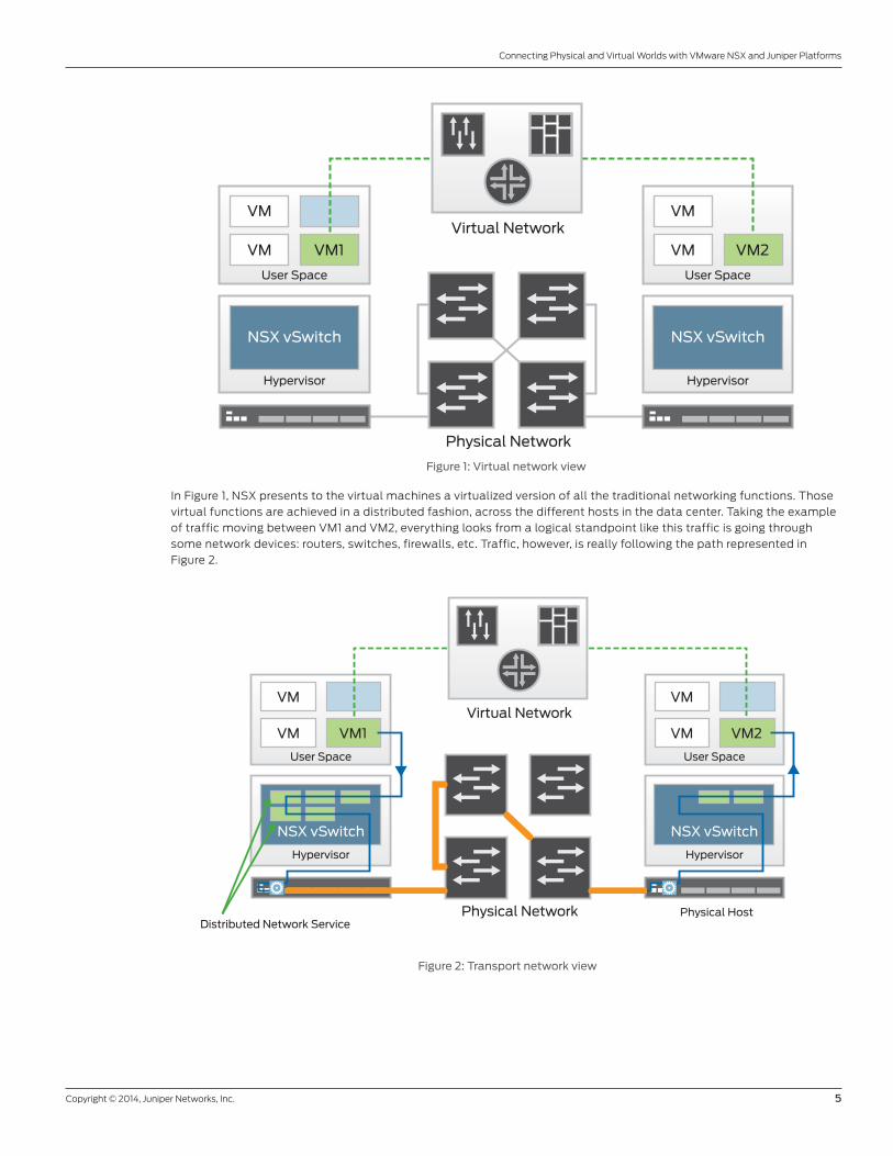
Figure 1: Virtual network view
In Figure 1, NSX presents to the virtual machines a virtualized version of all the traditional networking functions. Those
virtual functions are achieved in a distributed fashion, across the different hosts in the data center. Taking the example
of traffic moving between VM1 and VM2, everything looks from a logical standpoint like this traffic is going through
some network devices: routers, switches, firewalls, etc. Traffic, however, is really following the path represented in
Figure 2.
Figure 2: Transport network view
User Space
Hypervisor
VM1
NSX vSwitch
VM
VM
User Space
Hypervisor
Virtual Network
Physical Network
VM2
NSX vSwitch
VM
VM
User Space
Hypervisor
VM1
NSX vSwitch
VM
VM
User Space
Hypervisor
Virtual Network
Physical NetworkDistributed Network Service
Physical Host
VM2
NSX vSwitch
VM
VM
6 Copyright © 2014, Juniper Networks, Inc.
Connecting Physical and Virtual Worlds with VMware NSX and Juniper Platforms
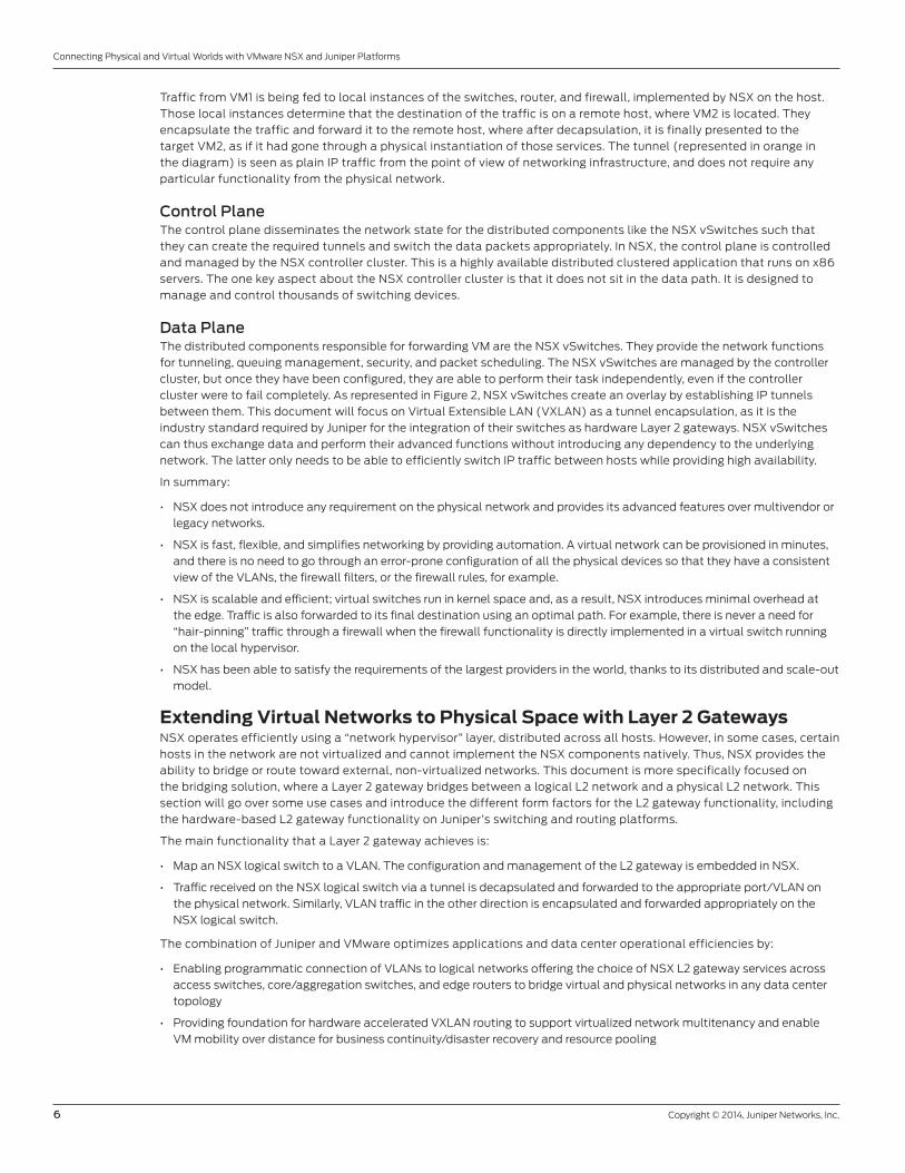
Traffic from VM1 is being fed to local instances of the switches, router, and firewall, implemented by NSX on the host.
Those local instances determine that the destination of the traffic is on a remote host, where VM2 is located. They
encapsulate the traffic and forward it to the remote host, where after decapsulation, it is finally presented to the
target VM2, as if it had gone through a physical instantiation of those services. The tunnel (represented in orange in
the diagram) is seen as plain IP traffic from the point of view of networking infrastructure, and does not require any
particular functionality from the physical network.
Control PlaneThe control plane disseminates the network state for the distributed components like the NSX vSwitches such that
they can create the required tunnels and switch the data packets appropriately. In NSX, the control plane is controlled
and managed by the NSX controller cluster. This is a highly available distributed clustered application that runs on x86
servers. The one key aspect about the NSX controller cluster is that it does not sit in the data path. It is designed to
manage and control thousands of switching devices.
Data Plane The distributed components responsible for forwarding VM are the NSX vSwitches. They provide the network functions
for tunneling, queuing management, security, and packet scheduling. The NSX vSwitches are managed by the controller
cluster, but once they have been configured, they are able to perform their task independently, even if the controller
cluster were to fail completely. As represented in Figure 2, NSX vSwitches create an overlay by establishing IP tunnels
between them. This document will focus on Virtual Extensible LAN (VXLAN) as a tunnel encapsulation, as it is the
industry standard required by Juniper for the integration of their switches as hardware Layer 2 gateways. NSX vSwitches
can thus exchange data and perform their advanced functions without introducing any dependency to the underlying
network. The latter only needs to be able to efficiently switch IP traffic between hosts while providing high availability.
In summary:
• NSX does not introduce any requirement on the physical network and provides its advanced features over multivendor or
legacy networks.
• NSX is fast, flexible, and simplifies networking by providing automation. A virtual network can be provisioned in minutes,
and there is no need to go through an error-prone configuration of all the physical devices so that they have a consistent
view of the VLANs, the firewall filters, or the firewall rules, for example.
• NSX is scalable and efficient; virtual switches run in kernel space and, as a result, NSX introduces minimal overhead at
the edge. Traffic is also forwarded to its final destination using an optimal path. For example, there is never a need for
“hair-pinning” traffic through a firewall when the firewall functionality is directly implemented in a virtual switch running
on the local hypervisor.
• NSX has been able to satisfy the requirements of the largest providers in the world, thanks to its distributed and scale-out
model.
Extending Virtual Networks to Physical Space with Layer 2 GatewaysNSX operates efficiently using a “network hypervisor” layer, distributed across all hosts. However, in some cases, certain
hosts in the network are not virtualized and cannot implement the NSX components natively. Thus, NSX provides the
ability to bridge or route toward external, non-virtualized networks. This document is more specifically focused on
the bridging solution, where a Layer 2 gateway bridges between a logical L2 network and a physical L2 network. This
section will go over some use cases and introduce the different form factors for the L2 gateway functionality, including
the hardware-based L2 gateway functionality on Juniper’s switching and routing platforms.
The main functionality that a Layer 2 gateway achieves is:
• Map an NSX logical switch to a VLAN. The configuration and management of the L2 gateway is embedded in NSX.
• Traffic received on the NSX logical switch via a tunnel is decapsulated and forwarded to the appropriate port/VLAN on
the physical network. Similarly, VLAN traffic in the other direction is encapsulated and forwarded appropriately on the
NSX logical switch.
The combination of Juniper and VMware optimizes applications and data center operational efficiencies by:
• Enabling programmatic connection of VLANs to logical networks offering the choice of NSX L2 gateway services across
access switches, core/aggregation switches, and edge routers to bridge virtual and physical networks in any data center
topology
• Providing foundation for hardware accelerated VXLAN routing to support virtualized network multitenancy and enable
VM mobility over distance for business continuity/disaster recovery and resource pooling
Copyright © 2014, Juniper Networks, Inc. 7
Connecting Physical and Virtual Worlds with VMware NSX and Juniper Platforms
• Allowing flexible workload placement and workload mobility
• Delivering a single pane of glass (NSX API) for configuring logical networks across hypervisors and physical switches
• Eliminating the need for IP multicast for the physical network
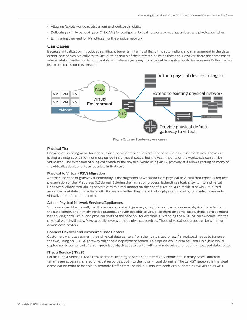
Use CasesBecause virtualization introduces significant benefits in terms of flexibility, automation, and management in the data
center, companies typically try to virtualize as much of their infrastructure as they can. However, there are some cases
where total virtualization is not possible and where a gateway from logical to physical world is necessary. Following is a
list of use cases for this service:
Figure 3: Layer 2 gateway use cases
Physical TierBecause of licensing or performance issues, some database servers cannot be run as virtual machines. The result
is that a single application tier must reside in a physical space, but the vast majority of the workloads can still be
virtualized. The extension of a logical switch to the physical world using an L2 gateway still allows getting as many of
the virtualization benefits as possible in that case.
Physical to Virtual (P2V) MigrationAnother use case of gateway functionality is the migration of workload from physical to virtual that typically requires
preservation of the IP address (L2 domain) during the migration process. Extending a logical switch to a physical
L2 network allows virtualizing servers with minimal impact on their configuration. As a result, a newly virtualized
server can maintain connectivity with its peers whether they are virtual or physical, allowing for a safe, incremental
virtualization of the data center.
Attach Physical Network Services/AppliancesSome services, like firewall, load balancers, or default gateways, might already exist under a physical form factor in
the data center, and it might not be practical or even possible to virtualize them (in some cases, those devices might
be servicing both virtual and physical parts of the network, for example.) Extending the NSX logical switches into the
physical world will allow VMs to easily leverage those physical services. These physical resources can be within or
across data centers.
Connect Physical and Virtualized Data CentersCustomers want to segment their physical data centers from their virtualized ones. If a workload needs to traverse
the two, using an L2 NSX gateway might be a deployment option. This option would also be useful in hybrid cloud
deployments comprised of an on-premises physical data center with a remote private or public virtualized data center.
IT as a Service (ITaaS)For an IT as a Service (ITaaS) environment, keeping tenants separate is very important. In many cases, different
tenants are accessing shared physical resources, but into their own virtual domains. The L2 NSX gateway is the ideal
demarcation point to be able to separate traffic from individual users into each virtual domain (VXLAN-to-VLAN).
VMware
VM VM VM
VM VM VM
VirtualEnvironment
Attach physical devices to logical
Provide physical defaultgateway to virtual
Extend to existing physical networkNSX
NSX
8 Copyright © 2014, Juniper Networks, Inc.
Connecting Physical and Virtual Worlds with VMware NSX and Juniper Platforms
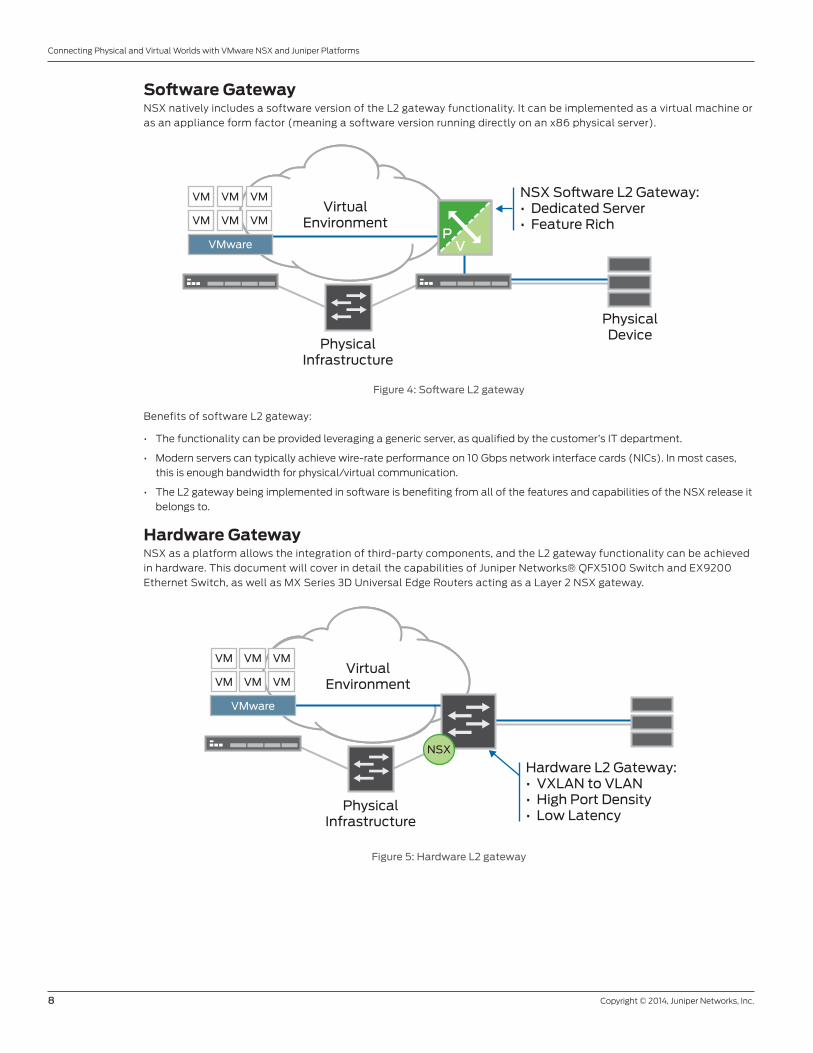
Software GatewayNSX natively includes a software version of the L2 gateway functionality. It can be implemented as a virtual machine or
as an appliance form factor (meaning a software version running directly on an x86 physical server).
Figure 4: Software L2 gateway
Benefits of software L2 gateway:
• The functionality can be provided leveraging a generic server, as qualified by the customer’s IT department.
• Modern servers can typically achieve wire-rate performance on 10 Gbps network interface cards (NICs). In most cases,
this is enough bandwidth for physical/virtual communication.
• The L2 gateway being implemented in software is benefiting from all of the features and capabilities of the NSX release it
belongs to.
Hardware GatewayNSX as a platform allows the integration of third-party components, and the L2 gateway functionality can be achieved
in hardware. This document will cover in detail the capabilities of Juniper Networks® QFX5100 Switch and EX9200
Ethernet Switch, as well as MX Series 3D Universal Edge Routers acting as a Layer 2 NSX gateway.
Figure 5: Hardware L2 gateway
VMware
VM VM VM
VM VM VMVirtual
Environment
PhysicalInfrastructure
PhysicalDevice
NSX So�ware L2 Gateway:• Dedicated Server• Feature Rich
PV
VMware
VM VM VM
VM VM VMVirtual
Environment
PhysicalInfrastructure
Hardware L2 Gateway:• VXLAN to VLAN• High Port Density• Low Latency
NSX
Copyright © 2014, Juniper Networks, Inc. 9
Connecting Physical and Virtual Worlds with VMware NSX and Juniper Platforms
Hardware L2 gateway provides several benefits, including:
• Port density: Juniper switches support deployments that scale from dozens to thousands of ports. This port density
allows for the connection of many devices as well as providing high bandwidth and redundancy to the NSX fabric. The
section on Juniper platforms provides more details on the scale and performance of various models.
• Deterministic performance and latency: Hardware forwarding latency is not impacted by whether the gateway is dealing
with a new flow, an existing flow, or a small or large packet. This results in lower latency, predictable and optimal traffic
flow, and higher throughput.
Technical Overview of the SolutionThis section presents the components involved in the solution as well as some technical details on how they work. It
is important to note that from an NSX standpoint, there is not much difference between a software and a hardware L2
gateway. Both are configured and managed similarly.
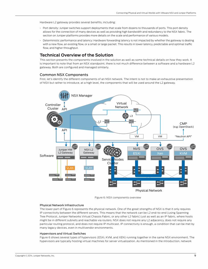
Common NSX ComponentsFirst, let’s identify the different components of an NSX network. The intent is not to make an exhaustive presentation
of NSX but rather to introduce, at a high level, the components that will be used around the L2 gateway.
Figure 6: NSX components overview
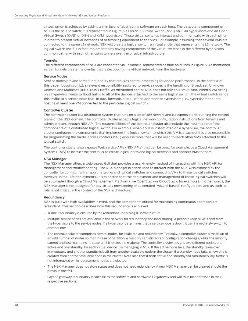
Physical Network InfrastructureThe lower part of Figure 6 represents the physical network. One of the great strengths of NSX is that it only requires
IP connectivity between the different servers. This means that the network can be L2 end-to-end (using Spanning
Tree Protocol, Juniper Networks Virtual Chassis Fabric, or any other L2 fabric) just as well as an IP fabric, where hosts
might be in different subnets and reachable via routers. NSX does not require any L2 adjacency, does not require any
particular routing protocol, and does not require IP multicast. IP connectivity is enough, a condition that can be met by
many legacy devices, even in multivendor environments.
Hypervisors and Virtual SwitchesFigure 6 shows several types of hypervisors (ESXi, KVM, and XEN) running together in the same NSX environment. The
hypervisors are typically hosting virtual machines for server virtualization. As mentioned in the introduction, network
ESXi
NVS
Xen
OVS
KVM
OVS
CMP(e.g. OpenStack)
Physical Network
So�wareService Nodes
Cluster
API
APIController
Cluster
NSX Manager
VirtualNetwork
“Neutron API”
Juniper HWL2 Gateway
NSX L2Gateway
VLANVLAN
VM VM
L3
L2
10 Copyright © 2014, Juniper Networks, Inc.
Connecting Physical and Virtual Worlds with VMware NSX and Juniper Platforms
virtualization is achieved by adding a thin layer of abstracting software on each host. The data plane component of
NSX is the NSX vSwitch; it is represented in Figure 6 as an NSX Virtual Switch (NVS) on ESXi hypervisors and an Open
Virtual Switch (OVS) on XEN and KVM hypervisors. These virtual switches interact and communicate with each other
in order to present virtual instances of networking equipment to the VMs. For example, assuming that several VMs are
connected to the same L2 network, NSX will create a logical switch, a virtual entity that represents this L2 network. The
logical switch itself is in fact implemented by having components of the virtual switches in the different hypervisors
communicating with each other using tunnels over the physical infrastructure.
TunnelsThe different components of NSX are connected via IP tunnels, represented as blue bold lines in Figure 6. As mentioned
earlier, tunnels create the overlay that is decoupling the virtual network from the hardware.
Service NodesService nodes provide some functionality that requires central processing for added performance. In the context of
this paper focusing on L2, a relevant responsibility assigned to service nodes is the handling of Broadcast, Unknown
Unicast, and Multicast (a.k.a. BUM) traffic. As mentioned earlier, NSX does not rely on IP multicast. When a VM sitting
on a hypervisor needs to flood traffic to all of the devices attached to the same logical switch, the virtual switch sends
this traffic to a service node that, in turn, forwards it to all of the appropriate hypervisors (i.e., hypervisors that are
hosting at least one VM connected to the particular logical switch).
Controller ClusterThe controller cluster is a distributed system that runs on a set of x86 servers and is responsible for running the control
plane of the NSX domain. The controller cluster accepts logical network configuration instructions from tenants and
administrators through NSX API. The responsibilities of the controller cluster also include the instantiation of the
components of a distributed logical switch. For example, when a VM is instantiated on a hypervisor, the controller
cluster configures the components that implement the logical switch to which this VM is attached. It is also responsible
for programming the media access control (MAC) address table that will be used to reach other VMs attached to the
logical switch.
The controller cluster also exposes Web service APIs (NSX APIs) that can be used, for example, by a Cloud Management
System (CMS) to instruct the controller to create logical ports and logical networks and connect VMs to them.
NSX ManagerThe NSX Manager offers a web-based GUI that provides a user-friendly method of interacting with the NSX API for
management and troubleshooting. The NSX Manager is hence used to interact with the NSX APIs exposed by the
controller for configuring transport networks and logical switches and connecting VMs to these logical switches.
However, in real-life deployments, it is expected that the deployment and management of those logical switches will
be automated through a Cloud Management Platform (like OpenStack or CloudStack, for example). In other words, the
NSX Manager is not designed for day-to-day provisioning or automated “wizard-based” configuration, and as such its
role is not critical in the context of the NSX architecture.
RedundancyNSX is built with high availability in mind, and the components critical for maintaining continuous operation are
redundant. This section describes how this redundancy is achieved.
• Tunnel redundancy is ensured by the redundant underlying IP infrastructure.
• Multiple service nodes are available in the network for redundancy and load sharing. A periodic keep alive is sent from
the hypervisors to the service nodes. If a hypervisor determines that a service node is down, it can immediately switch to
another one.
• The controller cluster comprises several nodes, for scale out and redundancy. Typically, a controller cluster is made up of
an odd number of nodes so that in case of partition, a majority can still accept configuration changes, while the minority
cannot and just maintains its state until it rejoins the majority. The controller cluster assigns two different nodes, one
active and one standby, for each virtual device it is managing in NSX. If the active node fails, the standby takes over
immediately and another standby is built from another available node in the cluster. If a standby node fails, a new one is
created from another available node in the cluster. Note also that if both active and standby fail simultaneously, traffic is
not interrupted while replacement nodes are elected.
• The NSX Manager does not store states and does not need redundancy. A new NSX Manager can be created should the
previous one fail.
• Layer 2 gateway redundancy is specific to the software and hardware L2 gateway and will thus be addressed in their
respective sections.
Copyright © 2014, Juniper Networks, Inc. 11
Connecting Physical and Virtual Worlds with VMware NSX and Juniper Platforms
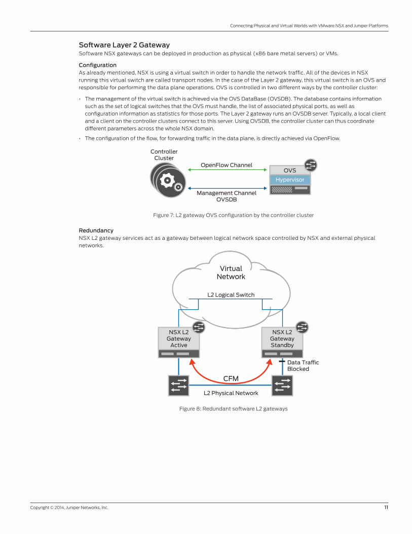
Software Layer 2 GatewaySoftware NSX gateways can be deployed in production as physical (x86 bare metal servers) or VMs.
ConfigurationAs already mentioned, NSX is using a virtual switch in order to handle the network traffic. All of the devices in NSX
running this virtual switch are called transport nodes. In the case of the Layer 2 gateway, this virtual switch is an OVS and
responsible for performing the data plane operations. OVS is controlled in two different ways by the controller cluster:
• The management of the virtual switch is achieved via the OVS DataBase (OVSDB). The database contains information
such as the set of logical switches that the OVS must handle, the list of associated physical ports, as well as
configuration information as statistics for those ports. The Layer 2 gateway runs an OVSDB server. Typically, a local client
and a client on the controller clusters connect to this server. Using OVSDB, the controller cluster can thus coordinate
different parameters across the whole NSX domain.
• The configuration of the flow, for forwarding traffic in the data plane, is directly achieved via OpenFlow.
Figure 7: L2 gateway OVS configuration by the controller cluster
RedundancyNSX L2 gateway services act as a gateway between logical network space controlled by NSX and external physical
networks.
Figure 8: Redundant software L2 gateways
Hypervisor
OVS
ControllerCluster
OpenFlow Channel
Management ChannelOVSDB
VirtualNetwork
CFM
L2 Logical Switch
L2 Physical Network
Data Tra�cBlocked
NSX L2Gateway
Active
NSX L2GatewayStandby
12 Copyright © 2014, Juniper Networks, Inc.
Connecting Physical and Virtual Worlds with VMware NSX and Juniper Platforms
Because the NSX controller cluster is not aware of the Layer 2 topology to which gateways connect, gateways must
perform loop prevention to avoid possible L2 loops. An example of this is represented in Figure 8, where two L2 gateways
are attached to the same physical L2 network. There is the potential for a loop between the NSX domain and the physical
L2 network through the two gateways. NSX prevents such loops by ensuring that at most one active L2 gateway is
attached to the same physical L2 network. L2 gateways use Ethernet connectivity fault management (CFM) frames on
the physical L2 network to detect if there are any other L2 gateways on the same network. CFM frames are multicast
frames and each contains an ID representing the L2 gateway. If an L2 gateway hears from another L2 gateway on the
same segment with an ID lower than its own, it becomes inactive, breaking any loop. The unique CFM ID used as a tie-
breaker is assigned to each L2 gateway by the NSX controller. Note that the loop detection mechanism also serves as a
redundancy mechanism. If the active gateway becomes inactive, the standby can start forwarding frames.
Using Bidirectional Forwarding Detection (BFD), the L2 gateways are also polling the service nodes over the tunnels
leading to them in order to check their liveliness. In case a service node is deemed unavailable, the gateway will switch
over to another active one.
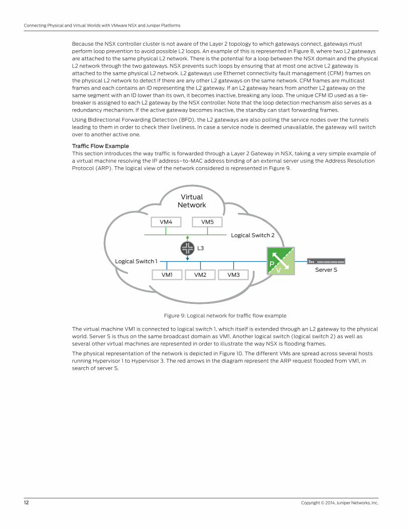
Traffic Flow ExampleThis section introduces the way traffic is forwarded through a Layer 2 Gateway in NSX, taking a very simple example of
a virtual machine resolving the IP address–to-MAC address binding of an external server using the Address Resolution
Protocol (ARP). The logical view of the network considered is represented in Figure 9.
Figure 9: Logical network for traffic flow example
The virtual machine VM1 is connected to logical switch 1, which itself is extended through an L2 gateway to the physical
world. Server S is thus on the same broadcast domain as VM1. Another logical switch (logical switch 2) as well as
several other virtual machines are represented in order to illustrate the way NSX is flooding frames.
The physical representation of the network is depicted in Figure 10. The different VMs are spread across several hosts
running Hypervisor 1 to Hypervisor 3. The red arrows in the diagram represent the ARP request flooded from VM1, in
search of server S.
VM1
VM4 VM5
Server S
Logical Switch 1
Logical Switch 2
VirtualNetwork
L3
VM2 VM3
PV
Copyright © 2014, Juniper Networks, Inc. 13
Connecting Physical and Virtual Worlds with VMware NSX and Juniper Platforms
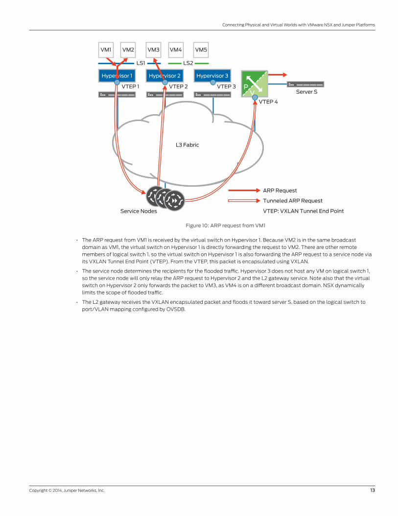
Figure 10: ARP request from VM1
• The ARP request from VM1 is received by the virtual switch on Hypervisor 1. Because VM2 is in the same broadcast
domain as VM1, the virtual switch on Hypervisor 1 is directly forwarding the request to VM2. There are other remote
members of logical switch 1, so the virtual switch on Hypervisor 1 is also forwarding the ARP request to a service node via
its VXLAN Tunnel End Point (VTEP). From the VTEP, this packet is encapsulated using VXLAN.
• The service node determines the recipients for the flooded traffic. Hypervisor 3 does not host any VM on logical switch 1,
so the service node will only relay the ARP request to Hypervisor 2 and the L2 gateway service. Note also that the virtual
switch on Hypervisor 2 only forwards the packet to VM3, as VM4 is on a different broadcast domain. NSX dynamically
limits the scope of flooded traffic.
• The L2 gateway receives the VXLAN encapsulated packet and floods it toward server S, based on the logical switch to
port/VLAN mapping configured by OVSDB.
Server S
ARP Request
VTEP: VXLAN Tunnel End Point
Tunneled ARP Request
L3 Fabric
Hypervisor 3
VTEP 3 PV
Hypervisor 2Hypervisor 1
VTEP 4
VTEP 2VTEP 1
LS1 LS2
VM1 VM2 VM3 VM4 VM5
Service Nodes
14 Copyright © 2014, Juniper Networks, Inc.
Connecting Physical and Virtual Worlds with VMware NSX and Juniper Platforms
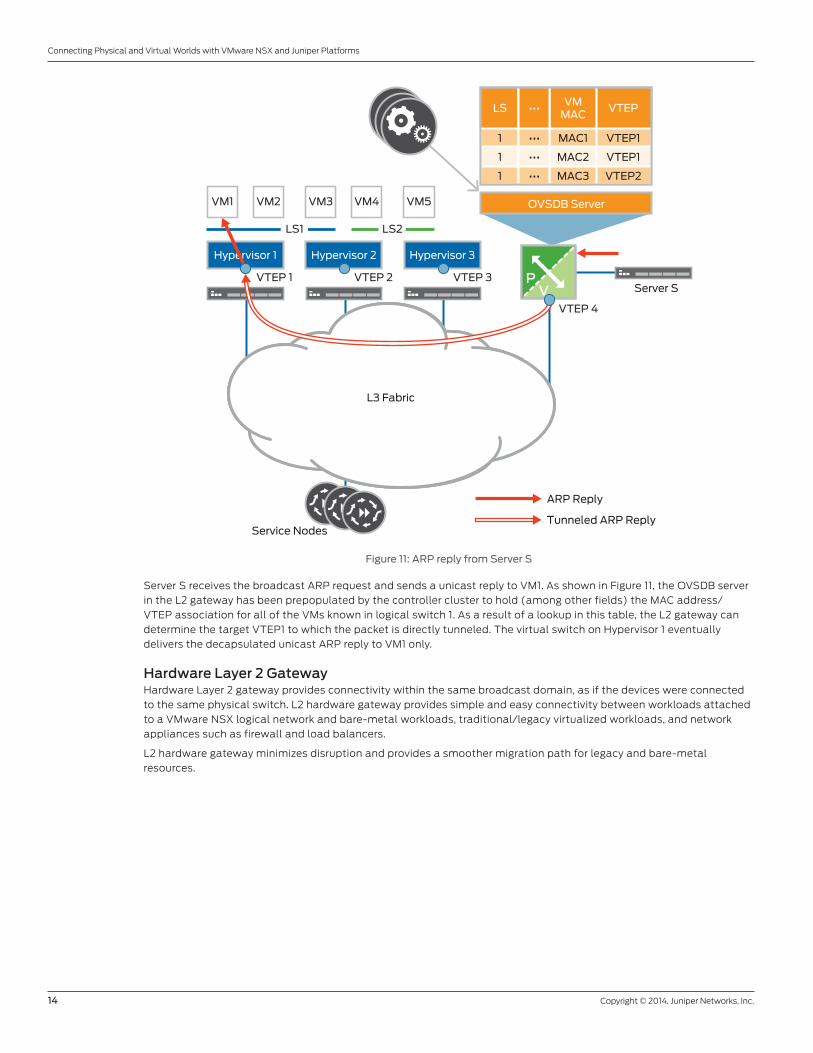
Figure 11: ARP reply from Server S
Server S receives the broadcast ARP request and sends a unicast reply to VM1. As shown in Figure 11, the OVSDB server
in the L2 gateway has been prepopulated by the controller cluster to hold (among other fields) the MAC address/
VTEP association for all of the VMs known in logical switch 1. As a result of a lookup in this table, the L2 gateway can
determine the target VTEP1 to which the packet is directly tunneled. The virtual switch on Hypervisor 1 eventually
delivers the decapsulated unicast ARP reply to VM1 only.
Hardware Layer 2 GatewayHardware Layer 2 gateway provides connectivity within the same broadcast domain, as if the devices were connected
to the same physical switch. L2 hardware gateway provides simple and easy connectivity between workloads attached
to a VMware NSX logical network and bare-metal workloads, traditional/legacy virtualized workloads, and network
appliances such as firewall and load balancers.
L2 hardware gateway minimizes disruption and provides a smoother migration path for legacy and bare-metal
resources.
Server S
ARP Reply
Tunneled ARP Reply
L3 Fabric
Hypervisor 3
VTEP 3 PV
Hypervisor 2Hypervisor 1
VTEP 4
VTEP 2VTEP 1
LS1 LS2
VM1 VM2 VM3 VM4 VM5
Service Nodes
OVSDB Server
LSVM
MACVTEP•••
1 MAC1 VTEP1•••
1 MAC2 VTEP1•••
1 MAC3 VTEP2•••
Copyright © 2014, Juniper Networks, Inc. 15
Connecting Physical and Virtual Worlds with VMware NSX and Juniper Platforms
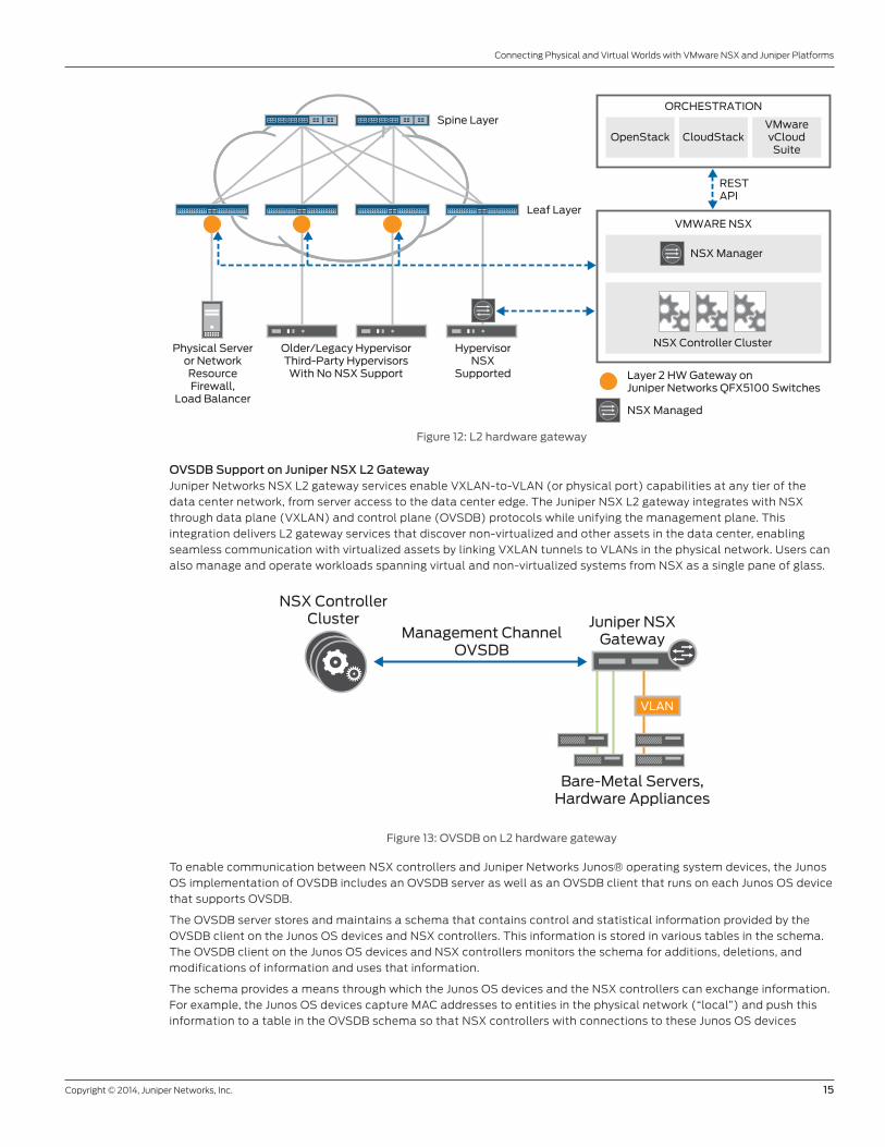
Figure 12: L2 hardware gateway
OVSDB Support on Juniper NSX L2 GatewayJuniper Networks NSX L2 gateway services enable VXLAN-to-VLAN (or physical port) capabilities at any tier of the
data center network, from server access to the data center edge. The Juniper NSX L2 gateway integrates with NSX
through data plane (VXLAN) and control plane (OVSDB) protocols while unifying the management plane. This
integration delivers L2 gateway services that discover non-virtualized and other assets in the data center, enabling
seamless communication with virtualized assets by linking VXLAN tunnels to VLANs in the physical network. Users can
also manage and operate workloads spanning virtual and non-virtualized systems from NSX as a single pane of glass.
Figure 13: OVSDB on L2 hardware gateway
To enable communication between NSX controllers and Juniper Networks Junos® operating system devices, the Junos
OS implementation of OVSDB includes an OVSDB server as well as an OVSDB client that runs on each Junos OS device
that supports OVSDB.
The OVSDB server stores and maintains a schema that contains control and statistical information provided by the
OVSDB client on the Junos OS devices and NSX controllers. This information is stored in various tables in the schema.
The OVSDB client on the Junos OS devices and NSX controllers monitors the schema for additions, deletions, and
modifications of information and uses that information.
The schema provides a means through which the Junos OS devices and the NSX controllers can exchange information.
For example, the Junos OS devices capture MAC addresses to entities in the physical network (“local”) and push this
information to a table in the OVSDB schema so that NSX controllers with connections to these Junos OS devices
HypervisorNSX
Supported
Physical Serveror NetworkResourceFirewall,
Load Balancer
Older/Legacy HypervisorThird-Party Hypervisors
With No NSX Support
Spine Layer
Leaf Layer
NSX Controller Cluster
NSX Manager
VMWARE NSX
OpenStack CloudStackVMwarevCloudSuite
RESTAPI
Layer 2 HW Gateway onJuniper Networks QFX5100 Switches
NSX Managed
ORCHESTRATION
VLAN
Juniper NSXGateway
Bare-Metal Servers,Hardware Appliances
Management ChannelOVSDB
NSX ControllerCluster
16 Copyright © 2014, Juniper Networks, Inc.
Connecting Physical and Virtual Worlds with VMware NSX and Juniper Platforms
can access the MAC addresses. Conversely, NSX controllers capture MAC addresses to entities in the virtual network
(“remote”) and push this information to a table in the OVSDB schema so that Junos OS devices with connections to
the NSX controllers can access the MAC addresses.
Redundancy/MultihomingVirtualized servers, bare-metal servers, and network services/appliances, among others, can multihome to two or
more L2 hardware NSX gateway devices for redundancy. If a network node functioning as an L2 NSX gateway fails, the
alternate node continues to service traffic for the servers or network appliances. The protocols and mechanisms for
supporting node redundancy is based on the data center fabric architecture. As an example, Juniper Networks Virtual
Chassis Fabric technology natively supports resiliency without any explicit configuration, as multiple network nodes
act as logical line cards in one large chassis providing unified management and control. These aspects are discussed in
more detail in the section on deployment architectures.
Traffic Flow ExampleMulticast in underlay is not required as Broadcast, Unknown Unicast, and Multicast (BUM) traffic is handled by a
service node that performs the replication. Replication for BUM traffic can be performed on the L2 hardware gateway
for optimal performance instead of leveraging the software-based service node.
The following diagrams illustrate the packet handling in an NSX environment with hardware L2 gateway. In the
following example, IP1 and IP2 VMs are connected to Hypervisor 1, and a bare-metal server IP5 is connected to the
Juniper L2 NSX gateway. Software VTEP is created on Hypervisor 1, and a hardware VTEP is created on Juniper L2 NSX
gateway as a part of the NSX configuration. Hypervisor 1, L2 NSX gateway, and NSX service nodes are connected to
each other using the same VXLAN network identifier (VNI) (L2/broadcast domain).
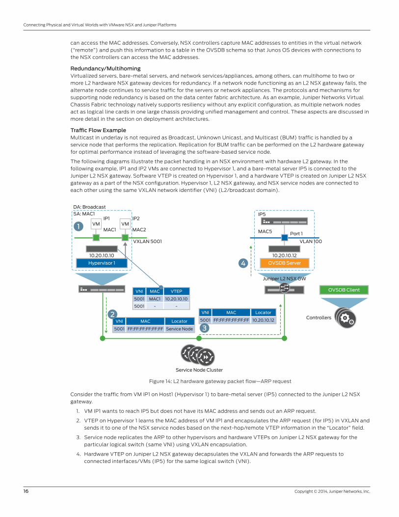
Figure 14: L2 hardware gateway packet flow—ARP request
Consider the traffic from VM IP1 on Host1 (Hypervisor 1) to bare-metal server (IP5) connected to the Juniper L2 NSX
gateway.
1. VM IP1 wants to reach IP5 but does not have its MAC address and sends out an ARP request.
2. VTEP on Hypervisor 1 learns the MAC address of VM IP1 and encapsulates the ARP request (for IP5) in VXLAN and
sends it to one of the NSX service nodes based on the next-hop/remote VTEP information in the “Locator” field.
3. Service node replicates the ARP to other hypervisors and hardware VTEPs on Juniper L2 NSX gateway for the
particular logical switch (same VNI) using VXLAN encapsulation.
4. Hardware VTEP on Juniper L2 NSX gateway decapsulates the VXLAN and forwards the ARP requests to
connected interfaces/VMs (IP5) for the same logical switch (VNI).
IP5IP1
DA: Broadcast
SA: MAC1IP2
MAC1 MAC2 MAC5 Port 1
10.20.10.12
OVSDB Client
OVSDB ServerHypervisor 1
VNI MAC VTEP
5001 MAC1 10.20.10.10
5001 - -
VNI MAC Locator
5001 FF:FF:FF:FF:FF:FF Service Node
VNI MAC Locator
5001 FF:FF:FF:FF:FF:FF 10.20.10.12
VLAN 100VXLAN 5001
Service Node Cluster
Juniper L2 NSX GW
Controllers
10.20.10.10
VMVM1
4
2
3
Copyright © 2014, Juniper Networks, Inc. 17
Connecting Physical and Virtual Worlds with VMware NSX and Juniper Platforms
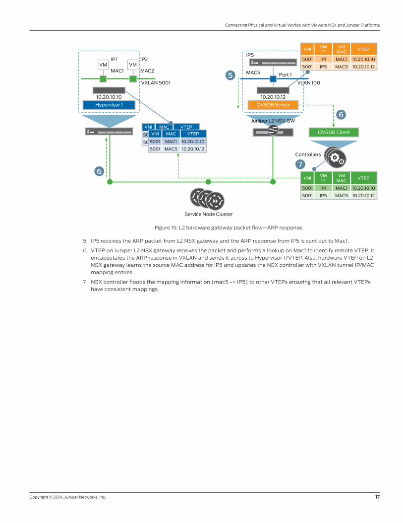
Figure 15: L2 hardware gateway packet flow—ARP response
5. IP5 receives the ARP packet from L2 NSX gateway and the ARP response from IP5 is sent out to Mac1.
6. VTEP on Juniper L2 NSX gateway receives the packet and performs a lookup on Mac1 to identify remote VTEP. It
encapsulates the ARP response in VXLAN and sends it across to Hypervisor 1/VTEP. Also, hardware VTEP on L2
NSX gateway learns the source MAC address for IP5 and updates the NSX controller with VXLAN tunnel IP/MAC
mapping entries.
7. NSX controller floods the mapping information (mac5 -> IP5) to other VTEPs ensuring that all relevant VTEPs
have consistent mappings.
VNI MAC VTEP
5001
5001
IP5IP1 IP2
MAC1 MAC2 MAC5 Port 1
10.20.10.12
OVSDB Client
OVSDB ServerHypervisor 1
VNI MAC VTEP
5001 MAC1 10.20.10.10
5001 MAC5 10.20.10.12
VLAN 100VXLAN 5001
Service Node Cluster
Juniper L2 NSX GW
Controllers
10.20.10.10
VMVM
5
VNIVMIP
VTEP
5001 IP1 10.20.10.10
5001 IP5
VMMAC
MAC1
MAC5 10.20.10.12
VNIVMIP
VTEP
5001 IP1 10.20.10.10
5001 IP5
VMMAC
MAC1
MAC5 10.20.10.12
6
6
7
18 Copyright © 2014, Juniper Networks, Inc.
Connecting Physical and Virtual Worlds with VMware NSX and Juniper Platforms
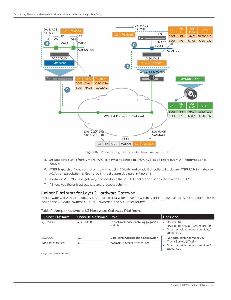
Figure 16: L2 hardware gateway packet flow—unicast traffic
8. Unicast data traffic from VM IP1/MAC1 is now sent across to IP5/MAC5 as all the relevant ARP information is
learned.
9. VTEP/Hypervisor 1 encapsulates the traffic using VXLAN and sends it directly to hardware VTEP/L2 NSX gateway.
VXLAN encapsulation is illustrated in the diagram depicted in Figure 16.
10. Hardware VTEP/L2 NSX gateway decapsulates the VXLAN packets and sends them across to IP5.
11. IP5 receives the unicast packets and processes them.
Juniper Platforms for Layer 2 Hardware Gateway L2 hardware gateway functionality is supported on a wide range of switching and routing platforms from Juniper. These
include the QFX5100 switches, EX9200 switches, and MX Series routers.
Table 1. Juniper Networks L2 Hardware Gateway Platforms
Juniper Platform Junos OS Software Role Use Case
QFX5100 14.1X53-D10 Top-of-rack data center aggregation switch
• Physical tier • Physical to virtual (P2V) migration • Attach physical network services/
appliances
EX9200 14.2R1 Data center aggregation/core switch • P2V data center connectivity • IT as a Service (ITaaS)• Attach physical network services/
appliances
MX Series routers 14.1R2 WAN/data center edge router
*Target availability: 2H 2014
IP5IP1 IP2
MAC1 MAC2 MAC5
DA: MAC5SA: MAC1DA: MAC5
SA: MAC1
DA: 10.20.10.12SA: 10.20.10.10
DA: MAC5SA: MAC1
Port 1
10.20.10.12
OVSDB Client
OVSDB ServerHypervisor 1
VNI MAC VTEP
5001 MAC1 10.20.10.10
5001 MAC5 10.20.10.12
VLAN 100VXLAN 5001
VXLAN Transport Network
Juniper L2 NSX GW
10.20.10.10
VMVM
11
10
VNIVMIP
VTEP
5001 IP1 10.20.10.10
5001 IP5
VMMAC
MAC1
MAC5 10.20.10.12
VNIVMIP
VTEP
5001 IP1 10.20.10.10
5001 IP5
VMMAC
MAC1
MAC5 10.20.10.12
9
8
L2 Payload
L2 PayloadUDPIPL2 VXLAN
5001
L2 Payload
Copyright © 2014, Juniper Networks, Inc. 19
Connecting Physical and Virtual Worlds with VMware NSX and Juniper Platforms
QFX5100 SwitchThe QFX5100 line of flexible, high-performance, low-latency, and feature-rich Layer 2 and Layer 3 switches are
optimized for virtualized data center environments and are ideal for top-of-rack as well as data center aggregation
deployments of various densities and speeds. This flagship platform from Juniper integrates with VMware NSX
and includes several features such as MPLS, Fibre Channel over Ethernet (FCoE), and the industry’s only topology-
independent in-service-software upgrade (TISSU) capability. QFX5100 switches can be deployed in various data
center fabric architectures such as Virtual Chassis Fabric, multichassis link aggregation (MC-LAG), and Layer 3 IP Clos
(spine/leaf).
The QFX5100 supports both dynamic provisioning (via NSX) as well as manual provisioning of VXLAN overlay tunnels.
EX9200The EX9200 line of programmable and modular Ethernet switches simplifies the deployment of cloud applications
in data center core/aggregation environments, serving as an ideal choice for data center consolidation and
interconnection.
MX SeriesThe MX Series is a family of high-performance, modular Ethernet services routers with powerful switching features.
The MX Series devices are designed for high-performance service providers and enterprises, and they are commonly
deployed in the data center core and interconnect as well as edge/core transport networks.
Both the EX9200 switch and MX Series routing platforms support OVSDB for integration with NSX. They can be
deployed in standalone mode or in L3 Clos architectures, and can support L2 as well as L3 NSX gateway functionality.
They can also be used to perform ingress replication for BUM traffic instead of using service node for the replication
functionality. Along with supporting the VXLAN-to-VLAN mapping, MX Series routers and EX9200 switches support
flexible mapping options from VXLAN to MPLS/VPLS or VXLAN to E-VPN.
Deployment Scenarios for Layer 2 Hardware GatewayBridging Physical and Virtual Tiers in Multitier Application Architectures Today, applications are deployed in a multitier (multilayer) manner in which presentation, application processing, and
data management functions are separated and can be deployed on virtualized or bare-metal servers. By segregating
an application into tiers, developers have the option of modifying or adding a specific layer instead of reworking the
entire application. Three-tier architectures are commonly chosen and are composed of a presentation tier, a domain
logic tier, and a data storage tier.
Anywhere from 40%-60% of servers today are virtualized, and while this number is on a definite upward trend, there
remain applications that still sit on non-virtualized servers. There could be many reasons for this—the application
might be tied to specific hardware, driver, license, or performance requirements, among others.
Because of licensing or performance issues, some database servers cannot be run as virtual machines. The result is
that a single application tier must reside on bare metal, but the vast majority of the workloads can still be virtualized.
The extension of a logical switch to the physical world using a L2 hardware gateway still provides many of the
virtualization benefits.
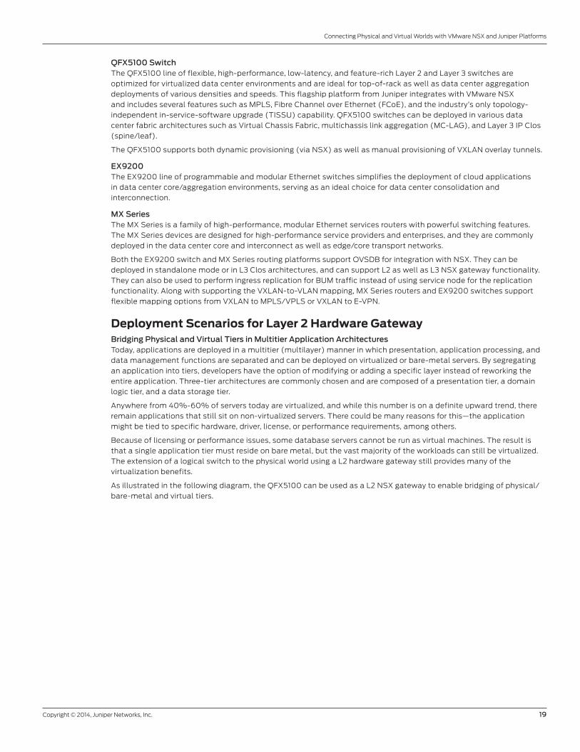
As illustrated in the following diagram, the QFX5100 can be used as a L2 NSX gateway to enable bridging of physical/
bare-metal and virtual tiers.
20 Copyright © 2014, Juniper Networks, Inc.
Connecting Physical and Virtual Worlds with VMware NSX and Juniper Platforms
Figure 17: Attach physical tier
Migrating Apps from Physical to Virtual ServersAs noted earlier, an increasing number of applications are being migrated from physical servers to virtualized instances
for gaining the numerous virtualization benefits such as workload mobility, efficient resource utilization, greater uptime,
and accelerated deployment, among others. Migration can be a complex activity that may require significant downtime.
L2 NSX gateway functionality can be leveraged in simplifying the migration of workload from physical to virtual by
preserving the IP address/subnet (L2 domain) during the migration process. Extending a logical switch to a physical
L2 network allows virtualizing servers with minimal impact on their configuration. As a result, the newly virtualized
server can maintain connectivity with its peers, whether they are virtual or physical, allowing for a safe, incremental
virtualization of the data center.
The QFX5100, serving as a Layer 2 NSX gateway, is an ideal choice for enabling the P2V migration.
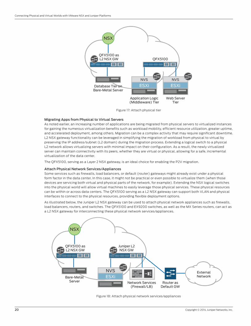
Attach Physical Network Services/AppliancesSome services such as firewalls, load balancers, or default (router) gateways might already exist under a physical
form factor in the data center, In this case, it might not be practical or even possible to virtualize them (when those
devices are servicing both virtual and physical parts of the network, for example). Extending the NSX logical switches
into the physical world will allow virtual machines to easily leverage those physical services. These physical resources
can be within or across data centers. The QFX5100 serving as a L2 NSX gateway can support both VLAN and physical
interfaces to connect to the physical resources, providing flexible deployment options.
As illustrated below, the Juniper L2 NSX gateway can be used to attach physical network appliances such as firewalls,
load balancers, routers, and switches. The QFX5100 and EX9200 switches, as well as the MX Series routers, can act as
a L2 NSX gateway for interconnecting these physical network services/appliances.
Figure 18: Attach physical network services/appliances
ESXi
NVS
ESXi
NVS
Web ServerTier
Application Logic(Middleware) Tier
Database Tier onBare-Metal Server
QFX5100 asL2 NSX GW QFX5100
NSX
ESXiNVS
Network Services(Firewall/LB)
Router asDefault GW
Bare-MetalServer
QFX5100 asL2 NSX GW
Juniper L2NSX GW
NSX
ExternalNetwork
Copyright © 2014, Juniper Networks, Inc. 21
Connecting Physical and Virtual Worlds with VMware NSX and Juniper Platforms
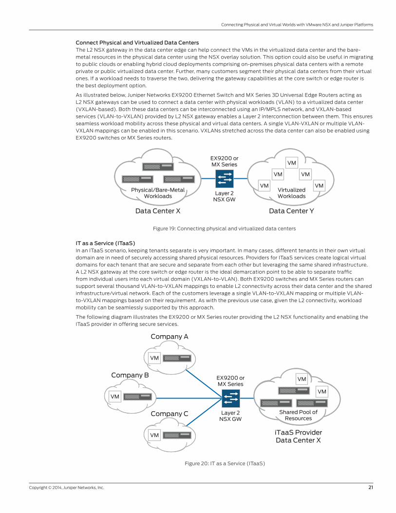
Connect Physical and Virtualized Data CentersThe L2 NSX gateway in the data center edge can help connect the VMs in the virtualized data center and the bare-
metal resources in the physical data center using the NSX overlay solution. This option could also be useful in migrating
to public clouds or enabling hybrid cloud deployments comprising on-premises physical data centers with a remote
private or public virtualized data center. Further, many customers segment their physical data centers from their virtual
ones. If a workload needs to traverse the two, delivering the gateway capabilities at the core switch or edge router is
the best deployment option.
As illustrated below, Juniper Networks EX9200 Ethernet Switch and MX Series 3D Universal Edge Routers acting as
L2 NSX gateways can be used to connect a data center with physical workloads (VLAN) to a virtualized data center
(VXLAN-based). Both these data centers can be interconnected using an IP/MPLS network, and VXLAN-based
services (VLAN-to-VXLAN) provided by L2 NSX gateway enables a Layer 2 interconnection between them. This ensures
seamless workload mobility across these physical and virtual data centers. A single VLAN-VXLAN or multiple VLAN-
VXLAN mappings can be enabled in this scenario. VXLANs stretched across the data center can also be enabled using
EX9200 switches or MX Series routers.
Figure 19: Connecting physical and virtualized data centers
IT as a Service (ITaaS)In an ITaaS scenario, keeping tenants separate is very important. In many cases, different tenants in their own virtual
domain are in need of securely accessing shared physical resources. Providers for ITaaS services create logical virtual
domains for each tenant that are secure and separate from each other but leveraging the same shared infrastructure.
A L2 NSX gateway at the core switch or edge router is the ideal demarcation point to be able to separate traffic
from individual users into each virtual domain (VXLAN-to-VLAN). Both EX9200 switches and MX Series routers can
support several thousand VLAN-to-VXLAN mappings to enable L2 connectivity across their data center and the shared
infrastructure/virtual network. Each of the customers leverage a single VLAN-to-VXLAN mapping or multiple VLAN-
to-VXLAN mappings based on their requirement. As with the previous use case, given the L2 connectivity, workload
mobility can be seamlessly supported by this approach.
The following diagram illustrates the EX9200 or MX Series router providing the L2 NSX functionality and enabling the
ITaaS provider in offering secure services.
Figure 20: IT as a Service (ITaaS)
Layer 2NSX GW
EX9200 orMX Series
VirtualizedWorkloads
Data Center Y
Physical/Bare-MetalWorkloads
Data Center X
VM
VM
VM
VM
VM
Layer 2NSX GW
EX9200 orMX Series
Shared Pool ofResources
iTaaS ProviderData Center X
Company A
VM
VM
Company B
VM
Company C
VM
VM
22 Copyright © 2014, Juniper Networks, Inc.
Connecting Physical and Virtual Worlds with VMware NSX and Juniper Platforms
Architectures for Deploying L2 NSX Gateway Using Juniper Platforms and TechnologiesNSX L2 gateway functionality on several Juniper platforms can be deployed in a flexible set of deployment
architectures. These include standalone, L3 Clos (spine/leaf), Virtual Chassis, and Virtual Chassis Fabric spine/
leaf modes. We describe the two most common architectures—L3 IP Clos and Virtual Chassis Fabric—deployed by
customers based on the scale, need for converged network, manageability, and other considerations/requirements.
Layer 3 IP Clos/ECMPClos networks are a kind of multistage circuit switching network, first formalized by Charles Clos in the 1950s.
This architecture delivers high bandwidth, low latency, and nonblocking connectivity that is key for large-scale modern
data centers, including massively scalable data center deployments.
Layer 3 Clos networks are commonly employed as the data center fabric in three-stage architectures comprising
several leaf nodes connected to all spine nodes. These are typically running BGP between the leaf and spine nodes
to achieve high performance and resiliency. Equal-cost multipath (ECMP) mechanisms are used to load-share traffic
across multiple spines (N-way multipathing).
The advantage of a Clos topology is that it can be nonblocking and allows predictable performance and scaling
characteristics, given that each leaf/access node is always reachable by another leaf/access node through just one
spine/aggregation device.
Server multihoming for bare-metal/virtualized servers (NIC teaming-based) can be achieved by enabling Virtual Chassis
in the top-of-rack/data center access layer wherein two switches act as a single logical device with a single IP address.
Overlay technologies such as VXLAN or L2 NSX gateway can be used to provide VM mobility across server nodes.
Further, L3 Clos can also be extended as a full-mesh overlay fabric based on VXLAN to enable seamless mobility and
service agility across the network.
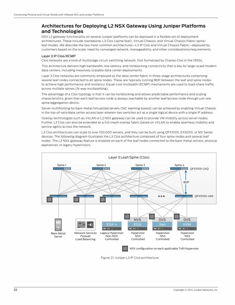
L3 Clos architectures can scale to over 100,000 servers, and they can be built using QFX5100, EX9200, or MX Series
devices. The following diagram illustrates the L3 Clos architecture composed of four spine nodes and several leaf
nodes. The L2 NSX gateway feature is enabled on each of the leaf nodes connected to the bare-metal servers, physical
appliances, or legacy hypervisors.
Figure 21: Juniper L3 IP Clos architecture
Bare-MetalServer
HypervisorNSX
Controlled
HypervisorNSX
Controlled
HypervisorNSX
Controlled
Legacy HypervisorNon-NSX
Controlled
QFX5100-48S
BGP
QFX5100-24QSpine 4Spine 3
Layer 3 Leaf/Spine (Clos)
Spine 2Spine 1
NSX configuration on each applicable ToR/Hypervisor
Network ServicesFirewall
Load Balancing
KVM0VS
Xen0VS
ESXiNVS
ESXi 4
Copyright © 2014, Juniper Networks, Inc. 23
Connecting Physical and Virtual Worlds with VMware NSX and Juniper Platforms
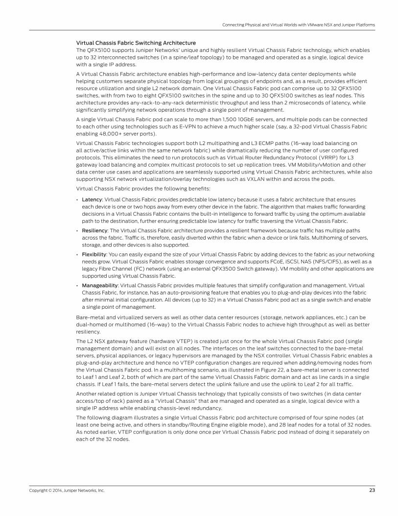
Virtual Chassis Fabric Switching ArchitectureThe QFX5100 supports Juniper Networks’ unique and highly resilient Virtual Chassis Fabric technology, which enables
up to 32 interconnected switches (in a spine/leaf topology) to be managed and operated as a single, logical device
with a single IP address.
A Virtual Chassis Fabric architecture enables high-performance and low-latency data center deployments while
helping customers separate physical topology from logical groupings of endpoints and, as a result, provides efficient
resource utilization and single L2 network domain. One Virtual Chassis Fabric pod can comprise up to 32 QFX5100
switches, with from two to eight QFX5100 switches in the spine and up to 30 QFX5100 switches as leaf nodes. This
architecture provides any-rack-to-any-rack deterministic throughput and less than 2 microseconds of latency, while
significantly simplifying network operations through a single point of management.
A single Virtual Chassis Fabric pod can scale to more than 1,500 10GbE servers, and multiple pods can be connected
to each other using technologies such as E-VPN to achieve a much higher scale (say, a 32-pod Virtual Chassis Fabric
enabling 48,000+ server ports).
Virtual Chassis Fabric technologies support both L2 multipathing and L3 ECMP paths (16-way load balancing on
all active/active links within the same network fabric) while dramatically reducing the number of user configured
protocols. This eliminates the need to run protocols such as Virtual Router Redundancy Protocol (VRRP) for L3
gateway load balancing and complex multicast protocols to set up replication trees. VM Mobility/vMotion and other
data center use cases and applications are seamlessly supported using Virtual Chassis Fabric architectures, while also
supporting NSX network virtualization/overlay technologies such as VXLAN within and across the pods.
Virtual Chassis Fabric provides the following benefits:
• Latency: Virtual Chassis Fabric provides predictable low latency because it uses a fabric architecture that ensures
each device is one or two hops away from every other device in the fabric. The algorithm that makes traffic forwarding
decisions in a Virtual Chassis Fabric contains the built-in intelligence to forward traffic by using the optimum available
path to the destination, further ensuring predictable low latency for traffic traversing the Virtual Chassis Fabric.
• Resiliency: The Virtual Chassis Fabric architecture provides a resilient framework because traffic has multiple paths
across the fabric. Traffic is, therefore, easily diverted within the fabric when a device or link fails. Multihoming of servers,
storage, and other devices is also supported.
• Flexibility: You can easily expand the size of your Virtual Chassis Fabric by adding devices to the fabric as your networking
needs grow. Virtual Chassis Fabric enables storage convergence and supports FCoE, iSCSI, NAS (NFS/CIFS), as well as a
legacy Fibre Channel (FC) network (using an external QFX3500 Switch gateway). VM mobility and other applications are
supported using Virtual Chassis Fabric.
• Manageability: Virtual Chassis Fabric provides multiple features that simplify configuration and management. Virtual
Chassis Fabric, for instance, has an auto-provisioning feature that enables you to plug-and-play devices into the fabric
after minimal initial configuration. All devices (up to 32) in a Virtual Chassis Fabric pod act as a single switch and enable
a single point of management.
Bare-metal and virtualized servers as well as other data center resources (storage, network appliances, etc.) can be
dual-homed or multihomed (16-way) to the Virtual Chassis Fabric nodes to achieve high throughput as well as better
resiliency.
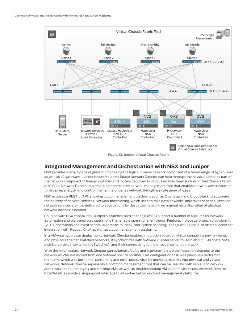
The L2 NSX gateway feature (hardware VTEP) is created just once for the whole Virtual Chassis Fabric pod (single
management domain) and will exist on all nodes. The interfaces on the leaf switches connected to the bare-metal
servers, physical appliances, or legacy hypervisors are managed by the NSX controller. Virtual Chassis Fabric enables a
plug-and-play architecture and hence no VTEP configuration changes are required when adding/removing nodes from
the Virtual Chassis Fabric pod. In a multihoming scenario, as illustrated in Figure 22, a bare-metal server is connected
to Leaf 1 and Leaf 2, both of which are part of the same Virtual Chassis Fabric domain and act as line cards in a single
chassis. If Leaf 1 fails, the bare-metal servers detect the uplink failure and use the uplink to Leaf 2 for all traffic.
Another related option is Juniper Virtual Chassis technology that typically consists of two switches (in data center
access/top of rack) paired as a “Virtual Chassis” that are managed and operated as a single, logical device with a
single IP address while enabling chassis-level redundancy.
The following diagram illustrates a single Virtual Chassis Fabric pod architecture comprised of four spine nodes (at
least one being active, and others in standby/Routing Engine eligible mode), and 28 leaf nodes for a total of 32 nodes.
As noted earlier, VTEP configuration is only done once per Virtual Chassis Fabric pod instead of doing it separately on
each of the 32 nodes.
24 Copyright © 2014, Juniper Networks, Inc.
Connecting Physical and Virtual Worlds with VMware NSX and Juniper Platforms
Figure 22: Juniper Virtual Chassis Fabric
Integrated Management and Orchestration with NSX and JuniperNSX provides a single pane of glass for managing the logical overlay network comprised of a broad range of hypervisors
as well as L2 gateways. Juniper Networks Junos Space Network Director can help manage the physical underlay part of
the network comprised of Juniper switches and routers deployed in various architectures such as Virtual Chassis Fabric
or IP Clos. Network Director is a smart, comprehensive network management tool that enables network administrators
to visualize, analyze, and control their entire underlay network through a single pane of glass.
NSX exposes a RESTful API, allowing cloud management platforms such as OpenStack and CloudStack to automate
the delivery of network services. Network provisioning, which used to take days or weeks, only takes seconds. Because
network services are now delivered to applications by the virtual network, no manual reconfiguration of physical
network devices is needed.
Coupled with NSX capabilities, Juniper’s switches such as the QFX5100 support a number of features for network
automation and plug-and-play operations that enable operational efficiency. Features include zero touch provisioning
(ZTP), operations and event scripts, automatic rollback, and Python scripting. The QFX5100 line also offers support for
integration with Puppet, Chef, as well as cloud management platforms.
In a VMware hypervisor deployment, Network Director enables integration between virtual computing environments
and physical Ethernet switched networks. It synchronizes with VMware vCenter server to learn about ESXi hosts, VMs,
distributed virtual switches (dvSwitches), and their connectivity to the physical switched network.
With this information, Network Director can automate VLAN and interface-related configuration changes to the
network as VMs are moved from one VMware host to another. This configuration task was previously performed
manually, which was both time-consuming and error-prone. Also, by providing visibility into physical and virtual
networks, Network Director represents a common management tool that can be used by both server and network
administrators for managing and tracking VMs, as well as troubleshooting VM connectivity issues. Network Director
RESTful APIs provide a single-point interface to all orchestration or cloud management platforms.
Bare-MetalServer
HypervisorNSX
Controlled
HypervisorNSX
Controlled
HypervisorNSX
Controlled
Legacy HypervisorNon-NSX
Controlled
QFX5100-48S
Leaf 28Leaf 1
QFX5100-24QSpine 4Spine 3
Virtual Chassis Fabric PodPod Single
Management
Spine 2Spine 1
Active
Single NSX configuration per Virtual Chassis Fabric pod
Network ServicesFirewall
Load Balancing
KVM0VS
Xen0VS
ESXiNVS
ESXi 4
RE Eligible Hot-Standby RE Eligible
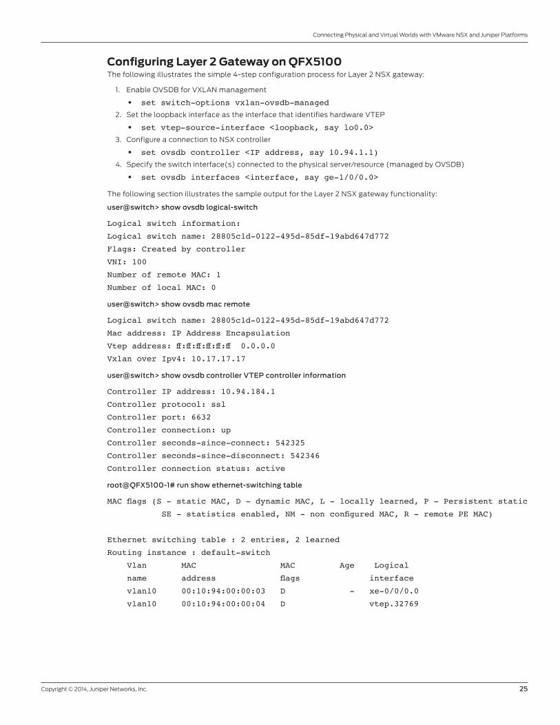
Copyright © 2014, Juniper Networks, Inc. 25
Connecting Physical and Virtual Worlds with VMware NSX and Juniper Platforms
Configuring Layer 2 Gateway on QFX5100The following illustrates the simple 4-step configuration process for Layer 2 NSX gateway:
1. Enable OVSDB for VXLAN management
• set switch-options vxlan-ovsdb-managed
2. Set the loopback interface as the interface that identifies hardware VTEP
• set vtep-source-interface <loopback, say lo0.0>
3. Configure a connection to NSX controller
• set ovsdb controller <IP address, say 10.94.1.1)
4. Specify the switch interface(s) connected to the physical server/resource (managed by OVSDB)
• set ovsdb interfaces <interface, say ge-1/0/0.0>
The following section illustrates the sample output for the Layer 2 NSX gateway functionality:
user@switch> show ovsdb logical-switch
Logical switch information:
Logical switch name: 28805c1d-0122-495d-85df-19abd647d772
Flags: Created by controller
VNI: 100
Number of remote MAC: 1
Number of local MAC: 0
user@switch> show ovsdb mac remote
Logical switch name: 28805c1d-0122-495d-85df-19abd647d772
Mac address: IP Address Encapsulation
Vtep address: ff:ff:ff:ff:ff:ff 0.0.0.0
Vxlan over Ipv4: 10.17.17.17
user@switch> show ovsdb controller VTEP controller information
Controller IP address: 10.94.184.1
Controller protocol: ssl
Controller port: 6632
Controller connection: up
Controller seconds-since-connect: 542325
Controller seconds-since-disconnect: 542346
Controller connection status: active
root@QFX5100-1# run show ethernet-switching table
MAC flags (S - static MAC, D - dynamic MAC, L - locally learned, P - Persistent static
SE - statistics enabled, NM - non configured MAC, R - remote PE MAC)
Ethernet switching table : 2 entries, 2 learned
Routing instance : default-switch
Vlan MAC MAC Age Logical
name address flags interface
vlan10 00:10:94:00:00:03 D - xe-0/0/0.0
vlan10 00:10:94:00:00:04 D vtep.32769
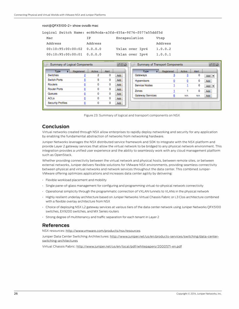
26 Copyright © 2014, Juniper Networks, Inc.
Connecting Physical and Virtual Worlds with VMware NSX and Juniper Platforms
root@QFX5100-2> show ovsdb mac
Logical Switch Name: ec8b9cda-a3fd-455a-9f76-f077a55ddf5d
Mac IP Encapsulation Vtep
Address Address Address
00:10:95:00:00:02 0.0.0.0 Vxlan over Ipv4 1.0.0.2
00:10:95:00:00:01 0.0.0.0 Vxlan over Ipv4 1.0.0.1
The following screen shot from NSX illustrates the summary of logical and transport components.
Figure 23: Summary of logical and transport components on NSX
ConclusionVirtual networks created through NSX allow enterprises to rapidly deploy networking and security for any application
by enabling the fundamental abstraction of networks from networking hardware.
Juniper Networks leverages the NSX distributed service framework and SDK to integrate with the NSX platform and
provide Layer 2 gateway services that allow the virtual network to be bridged to any physical network environment. This
integration provides a unified user experience and the ability to seamlessly work with any cloud management platform
such as OpenStack.
Whether providing connectivity between the virtual network and physical hosts, between remote sites, or between
external networks, Juniper delivers flexible solutions for VMware NSX environments, providing seamless connectivity
between physical and virtual networks and network services throughout the data center. This combined Juniper-
VMware offering optimizes applications and increases data center agility by delivering:
• Flexible workload placement and mobility
• Single pane-of-glass management for configuring and programming virtual-to-physical network connectivity
• Operational simplicity through the programmatic connection of VXLAN tunnels to VLANs in the physical network
• Highly resilient underlay architecture based on Juniper Networks Virtual Chassis Fabric or L3 Clos architecture combined
with a flexible overlay architecture from NSX
• Choice of deploying NSX L2 gateway services at various tiers of the data center network using Juniper Networks QFX5100
switches, EX9200 switches, and MX Series routers
• Strong degree of multitenancy and traffic separation for each tenant in Layer 2
ReferencesNSX resources: http://www.vmware.com/products/nsx/resources
Juniper Data Center Switching Architectures: http://www.juniper.net/us/en/products-services/switching/data-center-
switching-architectures
Virtual Chassis Fabric: http://www.juniper.net/us/en/local/pdf/whitepapers/2000571-en.pdf
Copyright © 2014, Juniper Networks, Inc. 27
Connecting Physical and Virtual Worlds with VMware NSX and Juniper Platforms
Appendix: Overview of Juniper Products for Layer 2 NSX Gateway
QFX5100 OverviewThe QFX5100 line of flexible, high-performance, low-latency, and feature-rich L2 and L3 switches has been optimized
for virtualized data center environments and is ideal for top-of-rack as well as data center aggregation deployments of
various densities and speeds.
The switches include:
• Rich L2 and L3 features including MPLS and Fibre Channel over Ethernet (FCoE)
• High availability with the industry’s only topology-independent in-service-software upgrade (TISSU)
• Designed-in Insight Technology software capability for microburst monitoring and reporting, as well as hotspot statistics
and visibility
• Up to 2.56 Tbps L2 and L3 performance and as low as 550 ns latency
• 1.5 GHz dual-core Intel CPU with 8 GB memory and 32 GB SSD storage
Four QFX5100 switch models are available:
• QFX5100-48S: 48 SFP/SFP+ ports and six QSFP+ 40GbE ports.
• QFX5100-96S: 96 SFP/SFP+ ports and eight QSFP+ 40GbE ports.
• QFX5100-24Q: 32 QSFP+ 40GbE ports
• QFX5100-48T: 48 ports of 10GbE copper + six QSFP+ 40 GbE ports
The QFX5100 can be deployed in a broad range of network architectures, including plug-and-play deployable
architectures such as Virtual Chassis, Virtual Chassis Fabric, and QFabric System with simplified management and
operation, as well as open architectures such as MC-LAG, spine/leaf, and Layer 3 Clos/ECMP.
This switch also has support for standards-based network virtualization protocols such as Virtual Extensible LAN
(VXLAN), Open vSwitch Database (OVSDB) protocol, and integration with OpenStack as well as SDN controllers such
as VMware NSX.
Insight Technology for Analytics and Intelligent Buffer ManagementThe QFX5100 provides dynamic buffer utilization monitoring and reporting with an interval of 10 milliseconds to
provide microburst and latency insight.
The intelligent buffer mechanism in the QFX5100 effectively absorbs traffic bursts while providing deterministic
performance, significantly increasing performance over static allocation.
Topology-Independent In-Service-Software Upgrade (TISSU)Improved resiliency and redundancy is a key requirement for top-of-rack switches in data center deployments.
QFX5100 switches allow Junos OS to run within a virtual machine (VM) on Linux. Junos OS runs in two separate VMs in
active and standby pairs; during software upgrade cycles, the switches seamlessly move to the newer software version
while maintaining intact data plane traffic. This true TISSU, an industry-first software upgrade feature for a fixed-
configuration top-of-rack switch, is supported across all Layer 2 and Layer 3 protocols.
AutomationThe QFX5100 switches support a number of features for network automation and plug-and-play operations. Features
include zero touch provisioning, operations and event scripts, automatic rollback, and Python scripting. The switch
offers support for integration with VMware NSX Layer 2 gateway services, as well as Puppet, Chef, and OpenStack.
28 Copyright © 2014, Juniper Networks, Inc.
Connecting Physical and Virtual Worlds with VMware NSX and Juniper Platforms
EX9200 OverviewThe EX9200 line of programmable Ethernet switches simplifies the deployment of cloud applications, server
virtualization, and rich media collaboration tools in campus and data center core and aggregation environments.
Three EX9200 switches are available in 4-slot, 8-slot, and 14-slot versions and can deliver up to 240 Gbps (full duplex)
per slot. A pass-through midplane design supports capacity of up to 13.2 Tbps for built-in migration to next-generation
deployments. Any combination of GbE, 10GbE, and 40GbE interfaces can be used, and the switches include support for
100GbE cards, when available.
EX9200 delivers a simple, secure, virtualized network environment that increases business agility, and helps
consolidate core and aggregation network layers to simplify network architecture and operations. EX9200 core
switches deliver a number of high availability features, including ISSU, graceful Routing Engine switchover (GRES), and
nonstop active routing (NSR) to ensure uninterrupted, carrier-class performance.
MX Series OverviewMX Series 3D Universal Edge Routers are a family of high-performance Ethernet services routers with powerful switching
features designed for high-performance service providers and enterprises. The MX Series has advanced MPLS, multicast,
quality-of-service (QoS), low-latency, and security capabilities. It provides flexibility and reliability to support a wide
range of advanced applications and services, including high-volume Internet data center internetworking.
The MX Series portfolio spans from smaller 20 Gbps systems through massive 80 Tbps systems. All major components
are field replaceable, increasing availability and decreasing mean time to repair (MTTR). Carrier-class reliability on the
MX Series includes GRES, NSR, unified in-service software upgrade (unified ISSU), and service-level resiliency with
features such as virtual private LAN service (VPLS) multihoming for Data Center Interconnect (DCI).
Junos Space and Network DirectorJunos Space is a comprehensive network management solution that simplifies and automates management of
Juniper’s network devices. Its centralized software control, management, and application programmability plays a
critical role in transforming traditional hardware-centric networks into SDN-ready underlay infrastructures.
Junos Space is a network management platform for deep element management and plug-and-play management
applications that reduce costs and quickly provision new services. It also includes a programmable SDK and APIs
for network customization. Components work together to deliver a unified network management and orchestration
solution that enables a more efficient network.
Junos Space Network Director is a plug-in application to the Junos Space Network Management Platform. It is a smart,
comprehensive, and automated network management tool that enables network administrators to visualize, analyze,
and control their entire network through a single pane of glass.
Network Director supports management of both virtual computing environments and physical Ethernet switched
networks. It synchronizes with a VMware vCenter server to learn about ESXi hosts, VMs, distributed virtual switches
(dvSwitches), and their connectivity to the physical switched network.
With this information, Network Director can automate VLAN and interface-related configuration changes to the
network as VMs are moved from one VMware host to another. This configuration task was previously performed
manually, which was both time-consuming and error-prone. Also, by providing visibility into physical and virtual
networks, Network Director represents a common management tool that can be used by both server and network
administrators for managing and tracking VMs, and troubleshooting VM connectivity issues.
Network Director provides a rich set of features that include:
• Zero touch provisioning, which simplifies policy-driven plug-and-play network deployment and network bring-up
operations
• Bulk provisioning, which enables faster service rollout and activation, even at logical or location level, and protects
against configuration errors
• Performance Analyzer, which provides real-time and trended monitoring of VMs, users, ports, and RF environments, and
network monitoring to optimize utilization
• VM Analyzer, which provides real-time physical and virtual topology views, tracks vMotion activity, and maintains
complete virtual network inventory
• Fabric Analyzer, which monitors and analyzes network fabric health
• Network Director API RESTful APIs, which provide a single-point interface to all orchestration tools
• VMware vCenter integration, to orchestrate the physical network based on vMotion activity
Copyright © 2014, Juniper Networks, Inc. 29
Connecting Physical and Virtual Worlds with VMware NSX and Juniper Platforms
2000589-002-EN Nov 2014
Copyright 2014 Juniper Networks, Inc. All rights reserved. Juniper Networks, the Juniper Networks logo, Junos and QFabric are registered trademarks of Juniper Networks, Inc. in the United States and other countries. All other trademarks, service marks, registered marks, or registered service marks are the property of their respective owners. Juniper Networks assumes no responsibility for any inaccuracies in this document. Juniper Networks reserves the right to change, modify, transfer, or otherwise revise this publication without notice.
APAC and EMEA Headquarters
Juniper Networks International B.V.
Boeing Avenue 240
1119 PZ Schiphol-Rijk
Amsterdam, The Netherlands
Phone: +31.0.207.125.700
Fax: +31.0.207.125.701
Corporate and Sales Headquarters
Juniper Networks, Inc.
1133 Innovation Way
Sunnyvale, CA 94089 USA
Phone: 888.JUNIPER (888.586.4737)
or +1.408.745.2000
Fax: +1.408.745.2100
www.juniper.net
To purchase Juniper Networks solutions,
please contact your Juniper Networks
representative at +1-866-298-6428 or
authorized reseller.
About Juniper NetworksJuniper Networks is in the business of network innovation. From devices to data centers, from consumers to cloud
providers, Juniper Networks delivers the software, silicon and systems that transform the experience and economics
of networking. The company serves customers and partners worldwide. Additional information can be found at
www.juniper.net.