Embed Size (px)
Citation preview
978-1-4244-4078-8/09/$25.00 ©2009 IEEE. 6.D.1-1
CONNECTING COMMERCIAL COMPUTERS TO AVIONICS SYSTEMS Youssef Laarouchi, Yves Deswarte, David Powell, Jean Arlat,
CNRS ; LAAS ; 7 avenue du colonel Roche/Université de Toulouse ; UPS, INSA, INP, ISAE ; LAAS ; F-31077 Toulouse, France
Eric de Nadai, EDYMI2 BP M03020, AIRBUS France, 316 route de Bayonne, F-31060 Toulouse, France
Abstract
In this paper, we present two case studies identified for new aircraft generations in which bidirectional communications are carried between on-board and off-board computers. These two case studies deal respectively with flight parameter calculation and enhanced maintenance operations for future aircraft. We emphasize the safety and security challenges in such communications, and propose a safe architecture allowing the connection of commercial computers to avionics systems, without altering any embedded software component behavior.
Introduction In avionics, every software component is
assigned a specific criticality level, according to the severity of the consequences of its failure. For instance, a task measuring altitude to calculate correct flight parameters is much more critical than one providing In-Flight Entertainment (IFE).
If a component is to support a critical task, it has to be designed and developed so that its confidence level is high enough to run such a critical task. The confidence level of a component depends on several parameters identified in [1]: validation (system development and verification in compliance with safety requirements), credibility (confidence attached to the source of data processed) and integrity (processing tasks are not corrupted). System designer can increase or decrease the level of these parameters to change the whole component confidence level according to the identified criticality level.
Consequently, the most critical tasks (with Development Assurance Level DAL-A in DO-178B [2]) require the highest level of validation, which means that they are designed and developed under strict constraints, which make them very expensive, economically speaking. On the contrary, the use of commercial off-the-shelf (COTS) components for
less critical tasks is more convenient since they offer extended functionalities at a more reasonable cost. However, they usually do not satisfy the validation requirements of highly critical tasks. The COTS development process is not strongly controlled; consequently these components are potentially unsafe and may contain security vulnerabilities. COTS components must thus limited to low DAL levels. But even in that case, if such COTS components were to interact with high DAL level ones, they could potentially alter the operation of critical tasks, which would be very dangerous.
A full isolation between each DAL level could be contemplated, but this would be too restrictive since it would not allow any inter-DAL-level communication at all, while such communication may be useful or, indeed, necessary. A more flexible solution is currently implemented in recent aircraft, such as the Airbus A380. It consists in allowing just downward information flows, so that critical components could control or send data to less critical ones. This is particularly useful for passive non-critical components. These components just execute orders coming from control units and so do not need bidirectional interaction. This behavior is similar to that of a diode in electronic circuits. Consequently, any upward information flow is totally forbidden, even acknowledgments, which still is too restrictive for some applications.
In the ArSec project, we identified two case studies in which communication between critical and less critical components has to be bidirectional: take-off profile calculation and enhanced maintenance operations. The first case study is currently not implemented in any aircraft. It is a part of research investigations aiming at shortening the aircraft stopover time, by reducing the pilot manual tasks. The second case is already implemented on a fixed embedded secure computer in the Airbus A380. In our study, we aim to make use of this computer more

6.D.1-2
flexible, by allowing it to be mobile, and even to interact with the open world (e.g., Internet), while keeping it as secure as before this change.
In this paper, we first present the two case studies by describing the current functionalities and the aimed new services. Safety and security aspects of these services drive our final architecture. Our solution is based on an information flow control model, in which bidirectional communication is taken into account. This model (Totel’s model [3]) is then described, and linked to both case studies. Finally, we briefly present the implementation of our architecture on a commercial computer securely connectable to the aircraft network.
Take-Off Profile Calculation
Current Procedure Establishing an aircraft take-off profile consists
in calculating a set of flight parameters necessary for a safe take-off (e.g., the take-off speed, the speed limit for aborting a flight, etc.). These parameters are defined according to two types of data:
• Airport data: these data are sent to the aircraft by the airport control system. The airport data could be: • fixed: for instance the length of the runway; • variable: for instance the state of the runway
(wet, sandy, etc.) or the weather pattern.
• Aircraft data: these data are essentially sent by the airline company to the aircraft system. The aircraft data could be: • fixed: for instance the aircraft model (Airbus
A380, Boeing 777, etc.); • variable: for instance the total weight, the load
distribution in the aircraft, etc. Currently, the data are manually processed by
the pilot (Figure 1), who gathers information from the airport and the companies using specific communication channels. He then has to calculate the take-off profile manually. Traditionally, the pilot does this using an abacus. More recently, to perform this calculation, pilots can use an application installed on a computer isolated from the aircraft network, but the take-off profile then has to be entered manually into the on-board flight management system.
Figure 1. Current Take-Off Profile Calculation
Procedure
The whole procedure would be faster if the data were to be processed by a laptop, for instance, that could be directly connected to the aircraft management system. Moreover, the action of a human operator in the current procedure leads to possible human-machine interaction errors especially if the pilot is under stress (e.g., requirement for fast take-off to respect timing constraints). In the next paragraph, we propose a new use of the pilot’s laptop computer, based on the existing profile calculation application.
New Procedure As described in Figure 1, the pilot currently has
to copy information from the different sources to the dedicated application, and the obtained result to the on-board computer connected to the flight management network.
We propose a new take-off profile calculation procedure, in which the pilot is no longer the main entity in charge of calculating the flight parameters and entering them into the aircraft system (Figure 2).
The dedicated profile calculation application presented in Figure 1 is installed on the Pilot Laptop in Figure 2. This laptop could be connected to the ground using several communication means, such as specific wireless channels or dedicated communication ports using wired connections. It is also possible that the company (or airport authority) uses a mass storage device (USB flash memory for example) to store the necessary data, and then gives it to the pilot who manually plugs the device into his laptop.
6.D.1-3
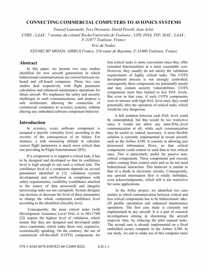
Figure 2. Proposed Take-Off Profile Calculation
Procedure
Given the different flight variables, the application proceeds to calculate the take-off profile, and sends it to on-board computer. The latter is considered as a critical component, and is developed to the highest DAL level. In our study, we suppose that this application is designed and developed by the aircraft manufacturer, and that this is done according to the strict conditions that would allow it to be validated to the same DAL level as the on-board computer.
Although the take-off profile calculation application is considered to be as safe as the on-board computer, the same is not true for the runtime platform of this application. Indeed, the application has to run on a COTS laptop with a COTS operating system (such as Windows XP). Moreover, we suppose that the Pilot Laptop can be used as a personal machine outside the aircraft. Such personal use allows the laptop to be connected to the Internet, with the attendant threats of malicious corruption of the underlying operating system.
To summarize, we consider that a safe application running on an unsafe operating system has to send information to a critical on-board computer. In the next paragraph, we analyze the different information flows existing in such an architecture in order to identify clearly the upward flows, i.e., flows from unsafe components to the highly critical ones.
Analysis of Information Flows in Proposed Procedure
As described in [1], criticality is an intrinsic property of each task, according to the severity of its failure. Given a certain criticality level, the system
designer has to ensure that this task has the same confidence level as the criticality level. To achieve this, fault tolerance mechanisms can be contemplated [4]. In this paper, we refer to these different levels as criticality levels. The term “integrity levels” is also used since it is common in the avionics literature. However, we have to keep in mind the idea that criticality is the most important parameter in such critical systems.
In our study, four criticality levels have been identified: FM (Flight Management), A/C OM (Aircraft Operation and Maintenance), A/C IS (Aircraft Information System) and OW (Open World), as shown in Figure 3.
Figure 3. New Information Flows for Pilot Laptop
In Figure 3, Task 1 corresponds to the take-off profile calculation task. Notice that this task is considered to be unsafe (since it is an open world component), even if the application itself is safe. This is due to low integrity level of the operating system, as explained before.
Task 1 interacts with Task 2, having the same criticality level. Task 2 may represent the airline company application in charge of sending aircraft data to Task 1. Since airline companies try to reduce the cost of this application, we suppose that it is implemented by a COTS component (which is quite realistic).
Task 3 may represent the airport application in charge of sending airport data to Task 1. This application may be developed under stricter constraints than Task 2 (we suppose that the airport has a strict policy concerning its software

6.D.1-4
development process), such that it can be considered that Task 3 belongs to the Aircraft Information System domain.
Task 4 corresponds to an application in charge of sending the calculated take-off parameters to the on-board equipment. It is implemented in the Flight Management domain, and is considered as the most critical component in this architecture.
In Figure 3, the arrows indicate the logical direction of information flow. For instance, Task 3 only sends data to Task 1, while Task 2 sends and receives data from Task 1. Downward flows (such as the communication between Task 3 and Task 1) are allowed because they do not induce any risk of affecting the correct operation of the higher-level task (Task 3). However, the communication between Task 4 and Task 1 has to be carefully controlled. In fact, such a communication allows an open world component (Task 1) to send data to a critical one (Task 4). We present later the mechanisms we propose to ensure that such an upward information flow can be achieved safely.
In the next paragraph, we describe the other case study [5] concerning enhanced maintenance operations, in which we also identified upward information flows.
Enhanced Maintenance Operations Maintenance operations present an important
economic challenge for airline companies since they define the stopover time of the aircraft. In fact, the aircraft is not allowed to take off without the authorization of ground maintenance operators. If maintenance operations take too much time, the airline company has to pay additional fees to the airport, and incurs additional costs due to the delays of subsequent flights. Large delays can also cause considerable customer dissatisfaction, which negatively impacts the brand image of the company. Consequently, the shorter this stopover time, the more profitable is the aircraft for the company.
Current Operation During the flight, the pilot and the on-board
equipment signal any faulty or unexpected behavior and save it in the On-board Log, where faults are classified according to their criticality. This log is
then transmitted to the maintenance operator (cf. Figure 4).
Figure 4. Current Maintenance Procedure
The maintenance operator analyzes the error reports, and follows the procedures indicated in manuals, by interacting with the aircraft system through a dedicated on-board maintenance computer. Currently, many maintenance manuals are still not electronic. Even when they exist, electronic manuals are prohibited from interacting directly with the aircraft in order to prevent any risk of corruption of critical components, as indicated in Figure 4. According to the severity of failures, the operator performs on-board tests to establish the cause of the error and carries out the appropriate repair. The presence of a human operator is important during maintenance operations because many decisions cannot be taken automatically. For instance, if a piece of equipment is declared to be faulty, the maintenance operator can decide that there is enough back-up redundancy, and allow the take-off under some conditions (e.g., replacing the faulty equipment during one of the next three stopovers).
We observe that, in this context, the human operator is in charge of collecting and analyzing failure data, and then performing the necessary actions according to the manuals. This kind of interaction is similar to the first case study. The maintenance operator, since he is working under the stress of urgency, is a potential source of interaction error. Allowing direct connection between the Maintenance Laptop and the tested on-board components would enhance maintenance operations by reducing human interaction failures and making the operations faster. In the next paragraph, we detail the use of a maintenance laptop.

6.D.1-5
Enhanced Operation Figure 5 shows an enhanced maintenance
procedure in which the human operator interacts with the aircraft system directly through his own Maintenance Laptop, where all electronic manuals are installed.
Figure 5. Enhanced Maintenance Procedure
The application installed on the Maintenance Laptop analyzes the flight log (On-board Log) and according to each failure, determines the list of actions to be performed to fix this failure.
The role of the maintenance operator consists in following instructions given by the manuals. In some cases, the operator will be in charge of verifying that a component is working correctly (for instance that a bulb is lit, etc.) and acknowledging that to the maintenance application. It is worth pointing out that the operator is assisted during all operations. He/she no longer has to do manual analysis of the log and make all decisions, since some of this can be done automatically by the Maintenance Laptop. However, the maintenance operator can still carry out specific decisions, e.g., in cases where economic issues have to be taken into account (as indicated earlier).
Analysis of Information Flows in New Procedure
The maintenance application has to interact with the on-board equipment. The equipment is not all at the same criticality level. To each piece of equipment is assigned a task in charge of interacting with the Maintenance Laptop and performing the maintenance tests and operations. Theses tasks have the same criticality as the piece of equipment they manage. In
Figure 6, we present different information flows during maintenance operations. Task 1 corresponds to the Maintenance Laptop application.
Figure 6. Information Flow in Enhanced
Maintenance Procedure
We note in this figure that all communications with Task 1 induce upward information flows from the OW domain to either the A/C IS domain or the A/C OM domain.
***
We see that, in both case studies, information has to be carried from low integrity level components (Maintenance Laptop or Pilot Laptop) to more critical on-board components. Both laptops are untrusted, since they are COTS hardware running COTS Operating Systems such as Windows. Such COTS OSes do not offer sufficient protection to the applications that they support, especially in case of malicious attack. In ArSec, we propose the use of Totel’s multilevel integrity model [3] to help in solving this problem.
Totel’s Model
Model Presentation Contrarily to classic integrity models (Biba [6],
Clark and Wilson [7]), Totel’s model allows communication from low integrity levels to high integrity ones without decreasing the integrity of the most critical components. The model introduces Validation Objects (VO) implementing fault tolerance techniques, which validate any data coming from a
6.D.1-6
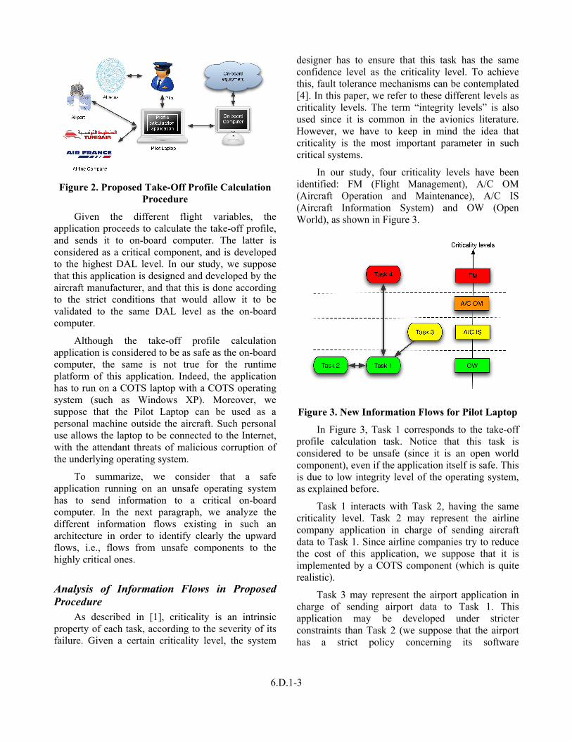
low integrity level to a high integrity one. Figure 7 presents the global software architecture that has to be deployed to allow bidirectional communications between objects having different integrity levels. Objects may be software components or complete hardware/software sub-systems. The arrows indicate the direction of logical information flows (as in Figure 3 and Figure 6).
Figure 7. Totel’s Model
As mentioned earlier, downward communication does not adversely affect operation of critical tasks. Thus, downward communication does not need any specific checking and is allowed. However, direct upward communication is forbidden. The only way for a high-integrity-level object to receive information from a low-integrity-level one is to use a specific communication channel. This channel is provided by a Trusted Computing Base (TCB) that offers a specific entry point for each upward communication flow. To avoid any violation of this principle, the TCB checks all communication in the system and implements the diode mechanism to prevent direct upward information flow between integrity levels. Only specific upward flows that go through the TCB and that are checked by VOs are allowed.
Figure 7 presents an example in which level 1 objects need to send information to object O4, which is the most critical one in the system. It has to be ensured that information coming from the lower levels does not alter the behavior of O4. To do this, all information coming from lower levels is validated by a Validation Object (VO) associated with O4. VOs are the only objects in the model allowed to receive data from lower integrity levels. They must have the integrity level of the object for which they validate information. Each VO contains fault tolerance
mechanisms to check the data flow. The implementation of each VO is tightly linked to the type of information that it checks. For example, in Figure 7, VO can compare or vote on redundant input data provided by the two instances of object O1.
The TCB of [3] consists of the information checking mechanisms, a microkernel and an integrity kernel. The microkernel is responsible for resource management, in particular to prevent low criticality tasks from consuming resources needed by more critical tasks. The micro-kernel is thus used to schedule tasks being run by different objects and to completely isolate the address spaces of each object. The integrity kernel also implements integrity-checking mechanisms that ensure that information flows are in the correct direction and that upward information flows are authorized only between specified entry and exit points of the TCB. The TCB must interact with the most critical objects of the system, so it has to be validated to the highest integrity level.
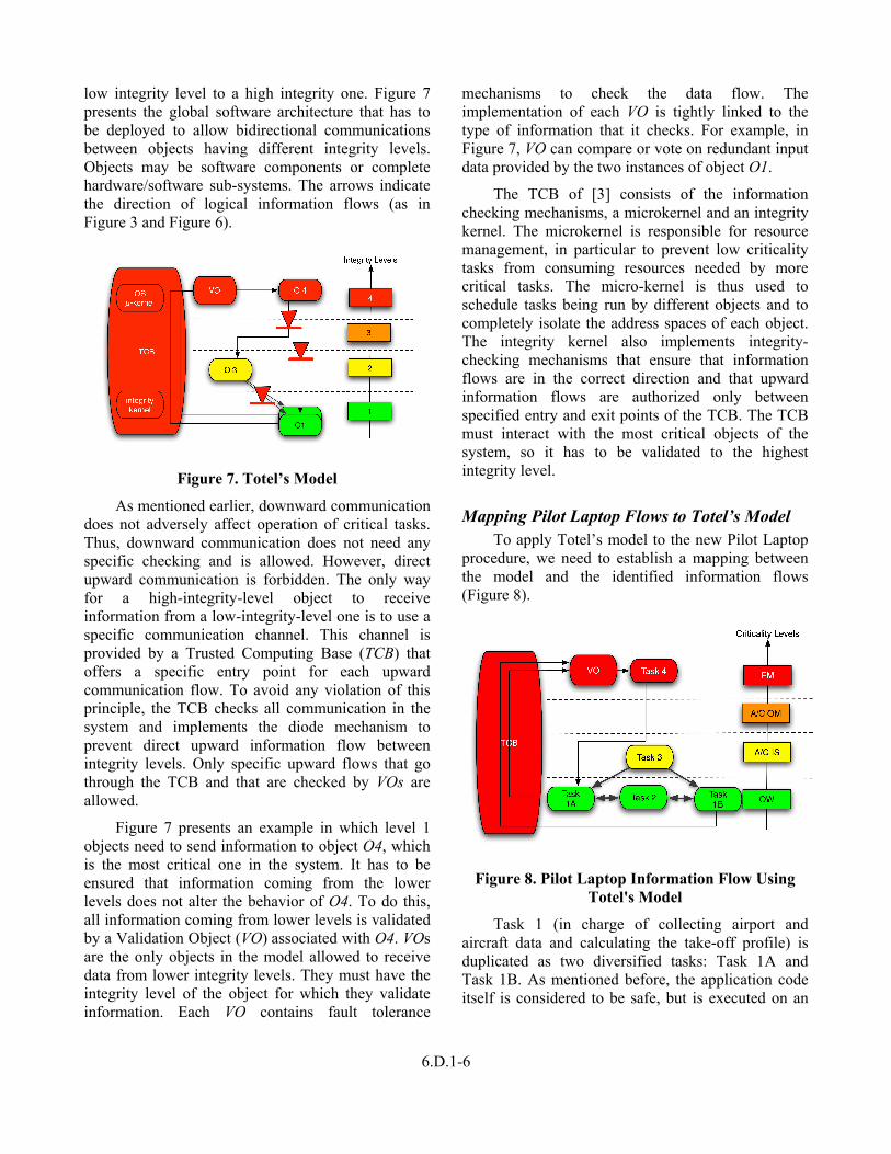
Mapping Pilot Laptop Flows to Totel’s Model To apply Totel’s model to the new Pilot Laptop
procedure, we need to establish a mapping between the model and the identified information flows (Figure 8).
Figure 8. Pilot Laptop Information Flow Using Totel's Model
Task 1 (in charge of collecting airport and aircraft data and calculating the take-off profile) is duplicated as two diversified tasks: Task 1A and Task 1B. As mentioned before, the application code itself is considered to be safe, but is executed on an

6.D.1-7
unsafe execution platform. Consequently, we adopted the technique of OS diversification, consisting in running replicas of the same application software, but on different operating systems, and using a voting mechanism (as part of the VO) to validate the results.
A similar mapping to Totel’s model can be done for the Maintenance Laptop information flows [5].
Diversification Using Virtualization The use of a laptop as a single physical machine
running COTS applications means that diversification of the execution platform must be carried out at the software level. For instance, the take-off parameter calculation task is executed on (at least) two different execution platforms. The first replica is implemented for a Windows-XP platform, the second for Linux (Figure 9). The only way to execute these two implementations simultaneously, on the same physical machine, is to use the virtualization approach [8]. Each replica of the calculation task is executed on a distinct virtual machine running its own guest operating system.
Figure 9. Diversification Using Virtualization
The use of virtualization raises the problem of the Human Machine Interface. In fact, each replica implements its own HMI, while only one HMI has to be visible to the pilot (the same applies to the maintenance operator). In ArSec [9], this problem is solved by:
1. Capturing all inputs from the user-visible HMI. The capture can be done at different levels (hypervisor, OS, specific API, etc.). In our case studies, the replicas are implemented using Java Swing API, and we have chosen this API level to
capture all I/O interactions. We used AspectJ to achieve the capture.
2. Forwarding these input events to the replicas. The replicas are already wrapped in a middleware listening to a virtual network socket, and waiting for these events. It is thus easy to forward the input events to both replicas at the same time.
3. Capturing the graphic outputs from each replica. These outputs are the result of each task replica process, and they are captured at the Java Swing API level.
4. Comparing the corresponding results of both virtual machines. Each virtual machine is assumed to deliver the same result, in the absence of faults [10]. In particular, all outputs issued by the two replicas (to the aircraft or to the laptop screen) should be identical. The comparison between the two copies of the same result is done by the Validation Object (VO) located in a safe virtual machine (running a dedicated OS that is much simpler than the COTS OSes, such that it can be easily validated at a higher level, see Figure 9).
5. Displaying (or forwarding to the aircraft) the result if both copies match. If the result consists in a modification of a graphic object, then this modification is done on the safe virtual machine. If the result is a packet sent to the aircraft network, then the safe virtual machine forwards this packet to the aircraft.
6. Or else raising an alarm and stopping the execution of both platforms.
In ArSec, the validation object is implemented in a safe virtual machine at the same criticality level as the hypervisor and the hardware. For our prototype implementation, we used Xen [11] as a hypervisor allowing isolation between different virtual machines.
The comparison mentioned in Step 5 assumes that both application replicas and OSes are deterministic, so that the results sent to the safe virtual machine correspond to the same information. Otherwise, the comparison might fail, and the validation object would continuously raise alarms. It is clear that this hypothesis is non realistic since the COTS operating systems use preemptive schedulers, which leads to non-determinism between different executions. Consequently, we have to ensure replica

6.D.1-8
determinism, even in presence of potential sources of non-determinism. This is done in practice by identifying each item of output information according to its semantics in the processing of the corresponding task, and by comparing the two copies with the same identification coming from the two replicas.
We note in Figure 8 that the TCB has to manage an information flow from the lowest criticality level (Open World) to the highest one (Flight Management). Such a transfer supposes that the TCB is designed and developed to satisfy the FM level validation requirements, but communicates with OW components, which raises validation problems, as discussed in the next paragraph.
TCB and Validation The TCB in Figure 8 is in charge of
communicating with Task 1 (running over a COTS OS in the OW domain) and Task 4 (running in the FM domain). Applications in the FM domain are critical since they directly impact flight safety. Such applications are thus as simple as possible and follow a very strict development process in order to meet the stringent validation requirements of this domain. The TCB, since it is communicating with the FM applications domain, has to be validated to the same level (FM) and thus also has to be as simple as possible. On the other hand, communicating with OW applications calls for the implementation of complex communication primitives, which in turn raises the complexity of the TCB, and makes it unsuitable for a validation according to the stringent FM domain requirements.
As an illustration of the resulting paradoxical situation, consider the example of network primitives. For the FM level, a deterministic network [12] (AFDX) is used for data exchange, while at the OW level, any common network can be used (such as IP over Ethernet). The TCB thus has to be simple to ensure deterministic behavior in the FM domain, while at the same time incurring the complexity of supporting IP communications.
The TCB complexity paradox can be tackled by decomposing the TCB to reduce the gap between application criticality levels (for example FM applications and OW applications). In ArSec, we propose the use of proxies. A proxy is a specific
object at criticality level b, in charge of forwarding data from a low criticality level a to a higher-level c, where a<b<c. Using proxies allow upward communication with multiple TCBs spanning narrower complexity gaps, thus making them easier to validate at their higher level.
In the Pilot Laptop case study, the TCB would be split into two parts (at least). The first one controls information between the OW and A/C IS domains. It consists in the laptop hardware, the hypervisor and the safe virtual machine (cf. Figure 10).
Figure 10. TCB Decomposition Using a Proxy
A proxy would be implemented in the A/C IS domain to convey information from the Pilot Laptop to the second TCB. The latter is in charge of communication between the A/C IS and FM domains. It would also be possible to split this second TCB into two further TCBs: one for A/C IS – A/C OM communication, and one for A/C OM – FM communication.
Conclusion In this paper, we have presented two case studies
that require information flows from low integrity level components to high integrity level ones. These cases correspond to the use of laptops to implement take-off profile calculation procedures and enhanced maintenance procedures. Both examples are not implemented in any aircraft yet, but are possible for future models.
We developed for each case study the upward information flows that have to be fully mastered to ensure safety and security properties of the whole system. We presented the use of Totel’s integrity

6.D.1-9
model to allow upwards flows while respecting these properties. This model is based on redundancy (for fault tolerance). Within ArSec, this is achieved through the use of virtualization as a technique allowing software diversification on a single physical laptop.
The use of redundancy raised the human-machine interface problem, which we solved in the ArSec prototype using interface event capture and forward mechanisms.
References [1] Y. Laarouchi, Y. Deswarte, D. Powell, J. Arlat, and E. de Nadai, “Criticality and Confidence Issues in Avionics,” 12th European Workshop on Dependable Computing (EWDC), Toulouse, France, May 14-15, 2009 <http://hal.archives-ouvertes.fr/hal-00381966/fr/>.
[2] Radio Technical Commission for Aeronautics (RTCA), “Software Considerations in Airborne Systems and Equipment Certification,” European Organization for Civil Aviation Electronics (EUROCAE), DO178-B, 1992.
[3] E. Totel, J. Blanquart, Y. Deswarte, and D. Powell, “Supporting multiple levels of criticality,” 28th IEEE Fault-Tolerant Computing Symposium (FTCS-28), Munich, Germany, 23-25 June 1998, pp. 70-79.
[4] A. Avizienis, J. Laprie, B. Randell, and C. Landwehr, “Basic Concepts and Taxonomy of Dependable and Secure Computing,” IEEE Transactions on Dependable and Secure Computing (TDSC), vol. 1, Issue 1, 2004, pp. 11-33.
[5] Y. Laarouchi, Y. Deswarte, D. Powell, J. Arlat, and E. de Nadai, “Ensuring Safety and Security for Avionics: a Case Study,” DAta Systems In Aerospace (DASIA 2009), Istanbul, Turkey, May 26-29, 2009, pp.178-183.
[6] K.J. Biba, “Integrity Considerations for Secure Computer Systems,” MITRE Co., Technical Report ESD-TR 76-372, 1977.
[7] D. Clark and D. Wilson, “A Comparison of Commercial and Military Computer Security Policies,” in IEEE Symposium on Security and Privacy, Oakland (CA), May 1987, pp. 184-194.
[8] J. Smith and R. Nair, Virtual Machines: Versatile Platforms for Systems and Processes, Morgan Kaufmann, 2005.
[9] Y. Laarouchi, Y. Deswarte, D. Powell, J. Arlat, and E. de Nadai, “Enhancing Dependability in Avionics Using Virtualization,” EuroSys Workshop on Virtualization Technology for Dependable Systems (VTDS'09), Nuremberg, Germany, March 31 - April 3, 2009, pp.13-17.
[10] D. Powell and P. Veríssimo, “Chapter 6.4: Replicated Software Components,” in Delta-4: A Generic Architecture for Dependable Computing, D. Powell Ed., Springer-Verlag, 1991, pp. 100-104.
[11] P. Barham, B. Dragovic, K. Fraser, S. Hand, T. Harris, A. Ho, R. Neugebauer, I. Pratt, and A. Warfield, “Xen and the art of virtualization,” 19th ACM Symposium on Operating Systems Principles (SOSP'03), October 19-22, 2003, Bolton Landing, NY, USA, pp. 164-177.
[12] P. Traverse, I. Lacaze, and J. Souyris, “Airbus Fly-By-Wire: A Total Approach To Dependability,” Building the Information Society, IFIP 18th World Computer Congress, Topical Sessions, 22–27 August 2004, Toulouse, France, Kluwer, pp. 191-212.
Acknowledgements This study is part of the ArSec project
(Architectures de Sécurités), a cooperation between LAAS-CNRS and AIRBUS France under AIRSYS convention. This study has been also partially supported by the European Network of Excellence ReSIST (Resilience for Survivability in IST), funded by the European Commission Framework Program 6, Contract Number 026764, http://www.resist-noe.org
28th Digital Avionics Systems Conference October 25-29, 2009