Embed Size (px)
Citation preview
CONFORMANCE TEST SUITE USER MANUAL
for Testing Interface and Application Code against the FACETM Technical Standard 3.1
CTS Version 3.1.0
NAVAIR Public Release 2021-24
Distribution Statement A –“Approved for public release; distribution is unlimited”
GTRI Document No. FACE100124 CTS Version 3.1.0, 11/30/2020 User Manual Copyright © 2020, Georgia Tech Applied
Research Corporation. This software, authored by Georgia Tech Research Institute under a contract awarded to and
managed by Georgia Tech Applied Research Corporation, was funded by the U.S. Government under Contract No. 19-
0044-21 and the U.S. Government has unlimited rights in this software. An “unlimited rights” license means that the U.S.
Government can use, modify, reproduce, release or disclose computer software in whole or in part, in any manner, and for
any purpose whatsoever, and to have or authorize others to do so.
Developed under Contract No. 19-0044-21 awarded to the Georgia Tech Applied Research Corporation (GTARC) by the
U.S. Government for the Georgia Tech Research Institute (GTRI) and Institute for Software Integrated Systems (ISIS),
Vanderbilt University. GTARC and Vanderbilt University disclaim all warranties with regard to this software, including all
implied warranties of merchantability and fitness for a particular use or purpose, validity of any intellectual property rights
or claims, or noninfringement of any third-party intellectual property rights. In no event shall GTARC or Vanderbilt
University be liable for any special, indirect or consequential damages or any damages whatsoever resulting from loss of use,
data or profits, whether in an action of contract, negligence or other tortious action, arising out of or in connection with the
use or performance of this software.
Future Airborne Capability Environment (FACE) Reference Architecture, 2012 The Open Group. FACE is a trademark of
The Open Group in the United States and other countries.
Georgia Tech Research Institute acknowledges The Open Group for permission to include text/figures derived from its
copyrighted Future Airborne Capability Environment (FACE) Reference Architecture. FACE is a trademark of The Open
Group in the United States and other countries.
iii
Table of Contents
1 Introduction ................................................................................................................................................................... 1
1.1 Context ...................................................................................................................................................................... 1
1.2 Tools Contained in the Test Suite ............................................................................................................................. 1
1.2.1 UsmIDLGenerator/DIG (Datamodel IDL Generator) ....................................................................................... 1
1.2.2 Ideal ................................................................................................................................................................... 2
1.2.3 DMVT (Data Model Validation Tool) .............................................................................................................. 2
1.2.4 FACE Conformance Application ...................................................................................................................... 3
1.2.5 Conformance Testing Workflow ....................................................................................................................... 3
2 Installation ..................................................................................................................................................................... 5
2.1 Installation on Linux (CentOS 7/RHEL 7) ............................................................................................................... 5
2.1.1 User Prerequisites .............................................................................................................................................. 5
2.1.2 System Requirements ........................................................................................................................................ 5
2.1.3 Language-specific Prerequisites ........................................................................................................................ 5
2.1.4 Installation of CTS ............................................................................................................................................ 9
2.1.5 Running CTS ................................................................................................................................................... 10
2.2 Installation on Windows (Windows 10).................................................................................................................. 11
2.2.1 User Prerequisites ............................................................................................................................................ 11
2.2.2 System Requirements ...................................................................................................................................... 11
2.2.3 Language-specific Prerequisites ...................................................................................................................... 12
2.2.4 Detailed Instructions for Installing Prerequisites ............................................................................................ 12
2.2.5 Installation of CTS .......................................................................................................................................... 20
3 Building the Sample Projects and Toolchains ............................................................................................................. 22
3.1 Build Flags .............................................................................................................................................................. 22
3.2 Linux generation ..................................................................................................................................................... 23
3.3 Windows generation ................................................................................................................................................ 24
3.3.1 Regarding Failing Test Results and Shared Data Model ................................................................................ 25
4 Theory of Operation .................................................................................................................................................... 26
4.1 Introduction to Methodology .................................................................................................................................. 26
4.2 Target Linker Method ............................................................................................................................................. 27
4.3 Host Linker Method ................................................................................................................................................ 28
4.4 Additional Methodology Information ..................................................................................................................... 28
4.4.1 OSS Testing Methodology .............................................................................................................................. 28
4.4.2 Java Testing Methodology .............................................................................................................................. 28
5 Toolchain Configuration Files .................................................................................................................................... 29
5.1 Introduction ............................................................................................................................................................. 29
5.2 Toolchain Files List ................................................................................................................................................. 29
5.3 Building a Toolchain File ........................................................................................................................................ 30
5.3.1 General Tab ..................................................................................................................................................... 30
5.3.2 File Extensions Tab ......................................................................................................................................... 31
5.3.3 Tools Tab ........................................................................................................................................................ 32
5.3.4 Compiler Specific Tab .................................................................................................................................... 34
5.3.5 Notes Tab ........................................................................................................................................................ 38
6 Project Configuration Files ......................................................................................................................................... 39
6.1 Project Configuration Builder Interface .................................................................................................................. 40
6.1.1 General Tab ..................................................................................................................................................... 40
6.1.2 Data Model Tab ............................................................................................................................................... 42
6.1.3 Gold Standard Libraries Tab ........................................................................................................................... 42
6.1.4 Objects/Libraries Tab ...................................................................................................................................... 43
6.1.5 Notes Tab ........................................................................................................................................................ 47
6.1.6 Project Info Tab ............................................................................................................................................... 48
7 Testing a UoC ............................................................................................................................................................. 50
7.1 Overview ................................................................................................................................................................. 50
7.2 Testing a PCS, TSS, PSSS, or IOSS UoC ............................................................................................................... 50
7.2.1 Test Procedures ............................................................................................................................................... 50
7.3 Testing an Operating System (OSS) UoC ............................................................................................................... 54
7.3.1 What the User Must Provide ........................................................................................................................... 54
7.3.2 Test Procedures ............................................................................................................................................... 54
7.4 Testing a Data Model .............................................................................................................................................. 60
7.4.1 What the User Must Provide ........................................................................................................................... 60
7.4.2 Test Procedures ............................................................................................................................................... 60
7.5 Considerations ......................................................................................................................................................... 61
7.5.1 Testing an Ada Segment ................................................................................................................................. 61
7.5.2 Testing a Java Segment ................................................................................................................................... 61
7.6 Viewing Test Suite Results ..................................................................................................................................... 61
8 References ................................................................................................................................................................... 64
Appendix A Using the CTS via Command line Interface (CLI) ......................................................................................... 65
Appendix B Glossary........................................................................................................................................................... 67
Appendix C Constraints....................................................................................................................................................... 68
Appendix D Issues ............................................................................................................................................................... 69

Appendix E Acknowledgments ........................................................................................................................................... 70
List of Figures
Figure 1-1. The workflow of FACE development and conformance testing. ........................................................................... 3
Figure 2-1. The system properties interface. ........................................................................................................................... 13
Figure 2-2. The environment variables interface. ................................................................................................................... 13
Figure 2-3. The new system variable interface. ...................................................................................................................... 14
Figure 2-4. Input values in the system variable dialogue. ....................................................................................................... 14
Figure 2-5. The environment variables dialogue. ................................................................................................................... 15
Figure 2-6. The PATH variable dialogue, with the JAVA_HOME environment variable outlined in red. ............................ 16
Figure 2-7. They Python 2.7 environment variable near the top of the list, with the variable is outlined in red. ................... 17
Figure 2-8. The msys64 path declarations, with variables are outlined in red. ....................................................................... 18
Figure 2-9. Ant environment variable. .................................................................................................................................... 19
Figure 2-10. Pointing the system path to the relevant Ant directories, with the variables are outlined in red. ....................... 20
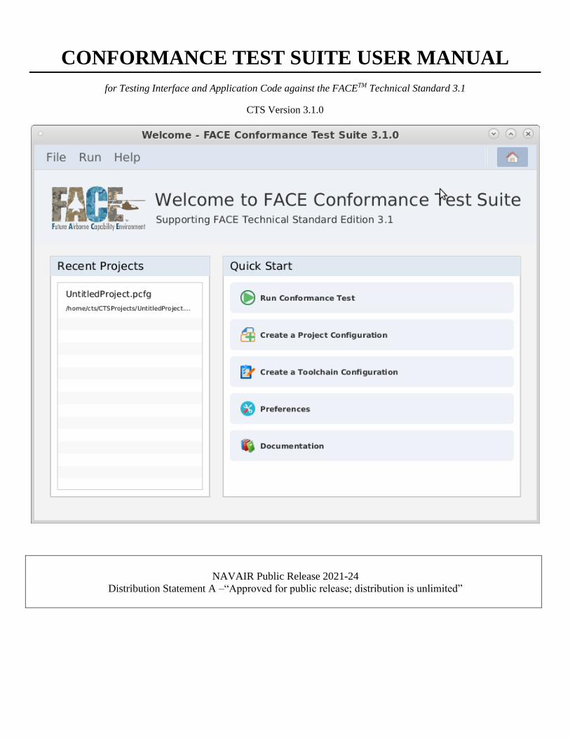
Figure 2-11. The CTS home screen. ....................................................................................................................................... 21
Figure 4-1. Linked source code interfaces matching and not matching the FACE Technical Standard. ................................ 26
Figure 4-2. The target linker GUI, found in the Toolchain Configuration Builder’s Tools tab. ............................................. 27
Figure 5-1. The Toolchain Files List. ...................................................................................................................................... 29
Figure 5-2. The Toolchain Configuration Builder with the General tab selected. .................................................................. 30
Figure 5-3. The Toolchain Configuration Builder with the File Extensions tab selected. ...................................................... 31
Figure 5-4. The Toolchain Configuration Builder with the Tools tab selected....................................................................... 32
Figure 5-5. The Toolchain Configuration Builder with the Tools tab selected....................................................................... 33
Figure 5-6. The Toolchain Configuration Builder with the Tools tab selected....................................................................... 34
Figure 5-7. The Toolchain Configuration Builder, with the Compiler Specific tab selected.................................................. 35
Figure 5-8. The Toolchain Configuration Builder with the Compiler Specific tab selected................................................... 37
Figure 5-9. The Allowed Definition editor. ............................................................................................................................ 38
Figure 5-10. The Project Configuration Builder, with the Notes tab selected. ....................................................................... 38
Figure 6-1. The Project Files List. .......................................................................................................................................... 39
Figure 6-2. The Project Configuration Builder with the General tab selected. ....................................................................... 40
Figure 6-3. The Project Configuration Builder with the Data Model tab selected. ................................................................. 42
Figure 6-4. The Project Configuration Builder with the Gold Standard Libraries tab selected. ............................................. 43
Figure 6-5. The Project Configuration Builder with the Objects/Libraries tab selected. ........................................................ 44
Figure 6-6. The Project Configuration Builder with the Objects/Libraries tab selected. ........................................................ 45
Figure 6-7. The Project Configuration Builder with the Objects/Libraries tab selected. ........................................................ 45
Figure 6-8. The Project Configuration Builder with the Objects/Libraries tab selected. ........................................................ 46
Figure 6-9. The Project Configuration Builder with the Objects/Libraries tab selected. ........................................................ 47
Figure 6-10. The Project Configuration Builder with the Objects/Libraries tab selected. ...................................................... 47

Figure 6-11. The Project Configuration Builder with the Notes tab selected. ........................................................................ 48
Figure 6-12. The Project Configuration Builder with the Project Info tab selected. ............................................................... 48
Figure 7-1. The GSL generation button. ................................................................................................................................. 51
Figure 7-2. The Project Configuration Builder, with the Objects/Libraries tab selected. ....................................................... 52
Figure 7-3. The Project Configuration Builder with the General tab selected. ....................................................................... 54
Figure 7-4. The Project Configuration Builder with the Gold Standard Libraries tab selected. ............................................. 55
Figure 7-5. The Project Configuration Builder with the Objects/Libraries tab selected. ........................................................ 56
Figure 7-6. The GSL generation button. ................................................................................................................................. 57
Figure 7-7. The Project Configuration Builder with the Objects/Library tab selected, within the Configuration subtab. ..... 59
Figure 7-8. A TSS's project configuration with the Data Model tab selected. ........................................................................ 60
Figure 7-9. A successful conformance test message. .............................................................................................................. 62
Figure 7-10. An example conformance test report. ................................................................................................................. 62
Figure 7-11. A conformance test report scrolled to show report contents. ............................................................................. 63
List of Tables
Table 2-1. The minimum requirements to run the CTS. ........................................................................................................... 5
Table 2-2. Dependencies that are required to successfully install the CTS on a Linux-based system...................................... 5
Table 2-3. Dependencies required for testing UoCs within the CTS. ....................................................................................... 6
Table 2-4. The minimum requirements to run on Windows. .................................................................................................. 11
Table 2-5. The prerequisites needed to install CTS on a Windows system. ........................................................................... 11
Table 2-6. UoC Testing Dependencies for Windows 10. ....................................................................................................... 12
Table 3-1. A list of all possible flags in executing the testUtility.py script. ........................................................................... 22
Table 4-1. Language standard that the CTS supports for a specific language. ....................................................................... 27
Table 4-2. Compiler flags for Non-OSS tests. ........................................................................................................................ 28
Table 4-3. Linker flags for Non-OSS tests. ............................................................................................................................. 28
Table 5-1. The list of intrinsic types that map to FACE’s exact types. ................................................................................... 36
Table 7-1. OSS Tests based on language and profile. ............................................................................................................. 56
Table A-1. The available flags to use with executing the CTS via CLI. ................................................................................. 66
i
Preface
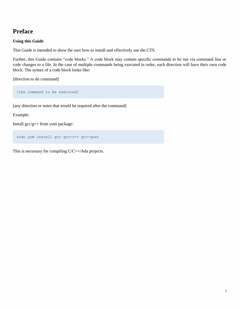
Using this Guide
This Guide is intended to show the user how to install and effectively use the CTS.
Further, this Guide contains “code blocks.” A code block may contain specific commands to be run via command line or
code changes to a file. In the case of multiple commands being executed in order, each direction will have their own code
block. The syntax of a code block looks like:
[direction to do command]
[any direction or notes that would be required after the command]
Example:
Install gcc/g++ from yum package:
This is necessary for compiling C/C++/Ada projects.
[the command to be executed]
sudo yum install gcc gcc-c++ gcc-gnat
1
1 Introduction
The Conformance Test Suite (CTS) tests Units of Conformance (UoCs) and data models that meet a subset of the
requirements in the FACE™ Technical Standard, Edition 3.1 [1]. All requirements the CTS is required to test are defined in
the Conformance Verification Matrix (CVM), provided by the FACE Consortium. All types of UoCs may be tested with the
CTS, including:
1. Portable Components Segment (PCS) UoCs
2. Platform Specific Services Segment (PSSS) UoCs
3. Transport Services Segment (TSS) UoCs
4. I/O Services Segment (IOSS) UoCs
5. Operating System Segment (OSS) UoCs
Testing procedures for each segment are listed in the sections contained in this user manual.
1.1 Context
There are two versions of the CTS: CTS 2.X and CTS 3.X (where X is a number that defines the version of the standard and
version of the CTS released. For example, CTS 3.1.0 represents supporting the 3.1 edition of the Technical Standard and is
the initial release of the CTS). Version 2.X is developed by Vanderbilt University, and version 3.X is developed by GTRI.
Use of developed code for the FACE Technical Standard, Edition 2.X cannot currently be tested with CTS 3.X, and developed
code for the FACE Technical Standard, Edition 3.X cannot be tested with 3.X. This document refers to version 3.X of the
CTS and will henceforth be referred to as “the CTS” unless otherwise delineated.
1.2 Tools Contained in the Test Suite
The CTS is comprised of multiple, separate tools which work together to test software components against the FACE
Technical Standard. There are four tools contained in the CTS: the UsmIDLGenerator/DIG (Data Model to IDL Generator),
Ideal, DMVT (Data Model Validation Tool), and FACE Conformance Application. The CTS uses each of these tools to
produce a conformance test result, as shown in Figure 1-1 below.
Using the CTS GUI allows for a user-friendly approach for FACE development and conformance testing, however, each of
these tools can be invoked separately via command line if needed. Although the CTS graphical user interface (GUI) is the
method in which users of the CTS are expected to use, it is beneficial for the user to know how to invoke the underlying CTS
tools at a command line level and understand how these tools work together to test for conformance. Instructions on how to
invoke each tool with command line-commands are detailed in Section 1.2.1, Section 1.2.2, Section 1.2.3, Section 1.2.4, and
Table A-1.
1.2.1 UsmIDLGenerator/DIG (Datamodel IDL Generator)
The UsmIDLGenerator/DIG is developed by ISIS (Institute for Software Integrated Systems)/Vanderbilt University. The tool
generates the IDL for the platform data types associated with a named template or Unit of Portability (UoP) in a FACE USM
(UoP Supplied Model). Used at CTS runtime, the UsmIDLGenerator/DIG is used to generate datatype IDL files which are
then compiled into source code for the language that the candidate UoC is written.
IDL (Interface Definition Language) is a standard written by the OMG (Object Management Group). A definition from the
OMG states, “IDL is a descriptive language used to define data types and interfaces in a way that is independent of the
programming language or operating system/processor platform. The IDL specifies only the syntax used to define the data
types and interfaces [1].” Used in the FACE Technical Standard, IDL is used to describe FACE Interfaces in a language-
agnostic way. FACE Interfaces described via IDL include the TSS API and IOSS API, among others.
2
To be used, the UsmIDLGenerator/DIG requires a valid installation of Java and Python 2.7 to successfully run. Although the
tool is intended to be invoked by the FACE Conformance Application, the generator may be invoked by directing a command
prompt to the root directory of the user’s installation of the CTS and executing:
1.2.2 Ideal
Ideal is a tool that is developed by GTRI. Ideal is a translator that maps IDL interfaces to a FACE supported software
language: Ada, Java, C99, and C++03. Ideal may also be used to generate language specific code from the data model, which
may be used to begin UoC development.
Although Ideal is intended to be invoked by the FACE Conformance Application, it may be invoked directly from the
command line. Ideal can only be directly invoked by directing a command prompt to the root directory of the user’s
installation of the CTS and executing:
A full list of command line options can be found by passing the script only the “-h” flag, when executed. A verbose output
can be given by adding the “--verbose” flag. Sample .idl files are located at “face_conformance_app/ideal/sample_idl.”
1.2.3 DMVT (Data Model Validation Tool)
The DMVT is developed by ISIS/Vanderbilt University. The tool takes the FACE Consortium written Shared Data Model
(SDM) and the user developed USM as inputs and tests the USM for FACE conformance. The SDM is available for download
on The Open Group’s website. Both the SDM and USM are stored with the file extension “.face.”
The DMVT sends/receives messages to the CTS via Transmission Control Protocol (TCP) with messages defined in protobuf
format. The DMVT may be used by pointing a terminal to the root directory of the user’s installation of the CTS, and
executing the following:
The DMVT may be invoked by executing the DAConformanceTest.jar file:
cd UsmIDLgen
java -jar UsmIDLgen_v31-2020.7.1.jar -out [IDL output directory] -uop [UoP name] -usm [USM location] -view [platform view name]
cd face_conformance_app/ideal
python ideal.py -I [location of folder that contains .idl] -c [IDL compiler, see README.md] [output dir] -- [target .idl file]
cd DMVT
java -jar DAConformanceTest_v31-2020.7.1.jar -usm [usm location] -sdm [sdm location] -l
[logfile location]
3
1.2.4 FACE Conformance Application
The FACE Conformance Application developed by GTRI includes the front-end GUI, backend processes to test for FACE
conformance, and the generation of the FACE conformance report after a UoC is tested.
The CTS GUI provides a means to configure the user’s UoC parameters into a FACE project configuration file (PCFG/.pcfg)
and toolchain configuration file (TCFG/.tcfg). More information about project configuration and toolchain configuration files
is found in the “Project Configuration Files” section and the “Toolchain Configuration Files,” section respectively.
After the PCFG/TCFG files are provided, the CTS links interfaces of either the user-supplied header files or the user-supplied
object files. The CTS is intended for use from the GUI but may be invoked via the command line. To use the CTS from the
command line, more information may be found in Appendix A. All instructions in this Guide use the CTS GUI aside from
Appendix A.
Each of these tools rely on each other for the CTS to provide accurate conformance test results. Figure 1-1 provides details
of a high-level workflow diagram on how each of the CTS’s contained tools interact with one another. The figure also details
an example for intended UoC development and UoC conformance testing process.
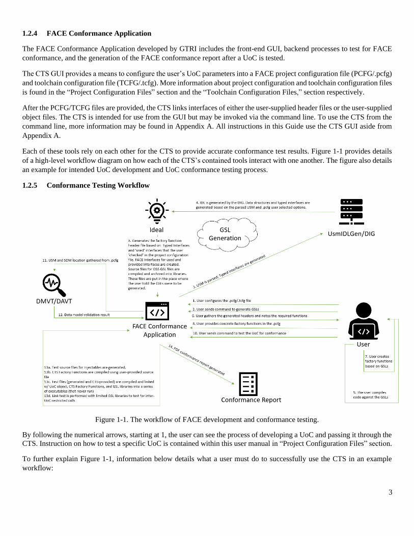
1.2.5 Conformance Testing Workflow
Figure 1-1. The workflow of FACE development and conformance testing.
By following the numerical arrows, starting at 1, the user can see the process of developing a UoC and passing it through the
CTS. Instruction on how to test a specific UoC is contained within this user manual in “Project Configuration Files” section.
To further explain Figure 1-1, information below details what a user must do to successfully use the CTS in an example
workflow:
4
1. The user must create or import a toolchain configuration file for the user’s specific compiler/linker/archiver tools,
either from scratch or basing it off one of the sample toolchains. The user must also create or import The Project
Configuration file by specifying the profile, segment, interfaces the UoC implements and interfaces it uses, and the
USM and corresponding SDM locations (if appropriate).
2. The user must click on the “Generate GSLs/Interface” button in the toolbar.
3. The USM’s location is taken from the configured project configuration file. The USM is parsed for TSS Typed
interfaces and/or Life Cycle Management (LCM) Stateful interfaces and be sent to the UsmIDLGen/DIG tool.
4. The UsmIDLGen/DIG tool translates the data structures and typed interfaces based on the USM to IDL.
5. Ideal generates the IDL into interface headers (C/C++/Ada spec files/Java) files based on the UoC programming
language. These files will be placed into a subfolder of the project folder as the “Gold Standard” folder (the relative
of the subfolder is include/FACE). This process also generates a text file in this location with all the include paths
the user should use to compile their code for conformance.
6. The user gathers the generated text file
7. Based on the CTS Factory Functions header (the generated text file), the user writes their implementation code (called
Factory Functions) that implements each interface being provided by the UoC from these generated interfaces created
in Step 5.
a. Implement each UoC interface based on the language constraints:
i. For C++ and Java, the implementation is a derived class for each interface being provided. The
base/abstract class is the interface class provided in the Gold Standard Library subfolder
include/FACE as generated by the CTS.
ii. For C and Ada, one must create implementations of the functions/procedures.
b. Next, for each FACE interface that the UoC is to “use” (access), the user must also implement the Injectable
interface for that interface.
8. The user adds the Factory Functions to the .pcfg file in the Objects/Libraries tab
9. The user compiles their UoC code using the generated headers or spec files or Java files (depending on language)
and the include paths (compiler paths or class paths) provided in the generated text file.
10. The user adds the object code to the CTS and runs the Conformance test by pressing the “Test UoC Conformance”
button.
11. The FACE Conformance Application invokes the DMVT/DAVT, sending the USM and SDM location
12. The DMVT validates the USM based on the SDM and sends back the result.
13. The FACE Conformance Application:
a. Tests source files for injectables that are generated.
b. Compiles CTS Factory Functions using the user-provided Factory Functions file.
c. Tests files (generated and CTS-provided) are compiled and linked with the UoC object(s), CTS Factory
Functions, and GSL libraries into a series of executables (that never are run, as the CTS only tests to see if a
UoC correctly links with the test executables) .
d. Link test is performed with limited GSL libraries to test for inter-UoC restricted calls.
14. A PDF conformance report is generated based on the results of step 13. The PDF report contains all test logs and
stack traces to those logs so the user can alter the UoC if there are any failures.
5
2 Installation
2.1 Installation on Linux (CentOS 7/RHEL 7)
2.1.1 User Prerequisites
To successfully install the CTS, the user must have root permission to access network-based repositories (such as “yum”),
package installation privileges, and privileges to change file permissions (via “chmod”).
Note: These permissions are necessary, as some dependencies are not installed by default. It is acknowledged that the CTS installation
process is not optimized for installation on government machines or on machines that restrict installation.
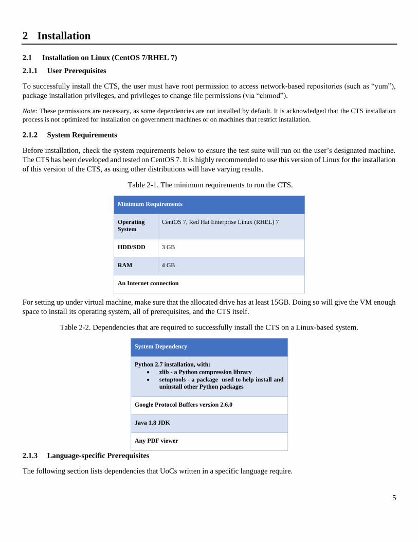
2.1.2 System Requirements
Before installation, check the system requirements below to ensure the test suite will run on the user’s designated machine.
The CTS has been developed and tested on CentOS 7. It is highly recommended to use this version of Linux for the installation
of this version of the CTS, as using other distributions will have varying results.
Table 2-1. The minimum requirements to run the CTS.
Minimum Requirements
Operating
System
CentOS 7, Red Hat Enterprise Linux (RHEL) 7
HDD/SDD 3 GB
RAM 4 GB
An Internet connection
For setting up under virtual machine, make sure that the allocated drive has at least 15GB. Doing so will give the VM enough
space to install its operating system, all of prerequisites, and the CTS itself.
Table 2-2. Dependencies that are required to successfully install the CTS on a Linux-based system.
System Dependency
Python 2.7 installation, with:
• zlib - a Python compression library
• setuptools - a package used to help install and
uninstall other Python packages
Google Protocol Buffers version 2.6.0
Java 1.8 JDK
Any PDF viewer
2.1.3 Language-specific Prerequisites
The following section lists dependencies that UoCs written in a specific language require.
6
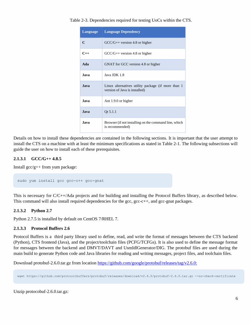
Table 2-3. Dependencies required for testing UoCs within the CTS.
Language Language Dependency
C GCC/G++ version 4.8 or higher
C++ GCC/G++ version 4.8 or higher
Ada GNAT for GCC version 4.8 or higher
Java Java JDK 1.8
Java Linux alternatives utility package (if more than 1
version of Java is installed)
Java Ant 1.9.0 or higher
Java Qt 5.1.1
Java Browser (if not installing on the command line, which
is recommended)
Details on how to install these dependencies are contained in the following sections. It is important that the user attempt to
install the CTS on a machine with at least the minimum specifications as stated in Table 2-1. The following subsections will
guide the user on how to install each of these prerequisites.
2.1.3.1 GCC/G++ 4.8.5
Install gcc/g++ from yum package:
This is necessary for C/C++/Ada projects and for building and installing the Protocol Buffers library, as described below.
This command will also install required dependencies for the gcc, gcc-c++, and gcc-gnat packages.
2.1.3.2 Python 2.7
Python 2.7.5 is installed by default on CentOS 7/RHEL 7.
2.1.3.3 Protocol Buffers 2.6
Protocol Buffers is a third party library used to define, read, and write the format of messages between the CTS backend
(Python), CTS frontend (Java), and the project/toolchain files (PCFG/TCFGs). It is also used to define the message format
for messages between the backend and DMVT/DAVT and UsmIdlGenerator/DIG. The protobuf files are used during the
main build to generate Python code and Java libraries for reading and writing messages, project files, and toolchain files.
Download protobuf-2.6.0.tar.gz from location https://github.com/google/protobuf/releases/tag/v2.6.0:
Unzip protocobuf-2.6.0.tar.gz:
sudo yum install gcc gcc-c++ gcc-gnat
wget https://github.com/protocolbuffers/protobuf/releases/download/v2.6.0/protobuf-2.6.0.tar.gz --no-check-certificate
7
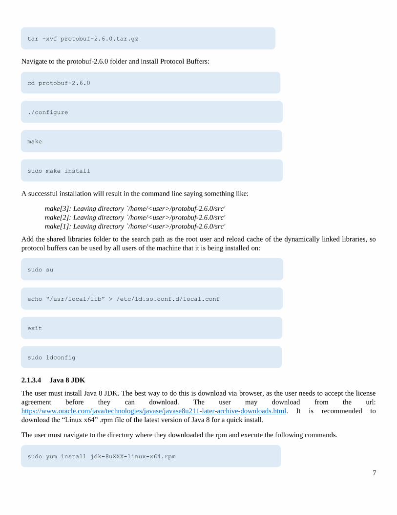
Navigate to the protobuf-2.6.0 folder and install Protocol Buffers:
A successful installation will result in the command line saying something like:
make[3]: Leaving directory `/home/<user>/protobuf-2.6.0/src'
make[2]: Leaving directory `/home/<user>/protobuf-2.6.0/src'
make[1]: Leaving directory `/home/<user>/protobuf-2.6.0/src'
Add the shared libraries folder to the search path as the root user and reload cache of the dynamically linked libraries, so
protocol buffers can be used by all users of the machine that it is being installed on:
2.1.3.4 Java 8 JDK
The user must install Java 8 JDK. The best way to do this is download via browser, as the user needs to accept the license
agreement before they can download. The user may download from the url:
https://www.oracle.com/java/technologies/javase/javase8u211-later-archive-downloads.html. It is recommended to
download the “Linux x64” .rpm file of the latest version of Java 8 for a quick install.
The user must navigate to the directory where they downloaded the rpm and execute the following commands.
tar -xvf protobuf-2.6.0.tar.gz
cd protobuf-2.6.0
./configure
make
sudo make install
sudo su
echo “/usr/local/lib” > /etc/ld.so.conf.d/local.conf
exit
sudo ldconfig
sudo yum install jdk-8uXXX-linux-x64.rpm

8
Optional note: If the user has different major versions of Java present on their installation system, the ‘alternatives’ utility may be used.
The utility allows the user to use different versions of applications in their environment. By default, it is installed in most Linux
distributions. If it is not installed, the user must install it via the normal means for installing packages for their Linux distribution. Then,
the user must initialize both the “java” and “javac” to the alternatives package. It is important to include both, as “java” is used to execute
Java bytecode, and “javac” is used to compile Java programs.
If the user executes…
…they should see a selection that contains their installation of Java.
If the user executes…
…they should see a selection that contains the location of their installation’s Java compiler.
2.1.3.5 Ant 1.9.x
Execute the following command to install Ant:
Note: The default installation version for Ant may be different than 1.9 for the user’s system. Check the package version in yum before
installing. This prerequisite is only required to build sample UoCs for Java. The user can exclude the Java UoCs when building sample
UoCs if desired.
2.1.3.6 Qt 5.1.1
Download qt-linux-opensource-5.1.1-x86_64-offline.run from location https://download.qt.io/archive/qt/5.1/5.1.1/
Execute the following commands to start the installer:
sudo /usr/sbin/alternatives --install /usr/bin/java java /usr/java/jdk1.8.0_XXX/bin/java 2000
sudo /usr/sbin/alternatives --install /usr/bin/javac javac /usr/java/jdk1.8.0_XXX/bin/javac 2000
sudo alternatives --config java
sudo alternatives --config javac
sudo yum install ant
wget https://download.qt.io/archive/qt/5.1/5.1.1/qt-linux-opensource-5.1.1-x86_64-offline.run --no-check-certificate
chmod 777 qt-linux-opensource-5.1.1-x86_64-offline.run
./qt-linux-opensource-5.1.1-x86_64-offline.run
9
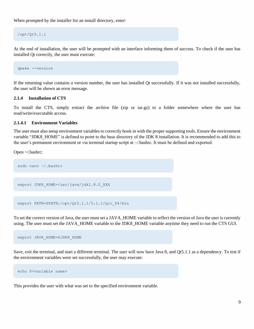
When prompted by the installer for an install directory, enter:
At the end of installation, the user will be prompted with an interface informing them of success. To check if the user has
installed Qt correctly, the user must execute:
If the returning value contains a version number, the user has installed Qt successfully. If it was not installed successfully,
the user will be shown an error message.
2.1.4 Installation of CTS
To install the CTS, simply extract the archive file (zip or tar.gz) to a folder somewhere where the user has
read/write/executable access.
2.1.4.1 Environment Variables
The user must also setup environment variables to correctly hook in with the proper supporting tools. Ensure the environment
variable “JDK8_HOME” is defined to point to the base directory of the JDK 8 installation. It is recommended to add this to
the user’s permanent environment or via terminal startup script at ~/.bashrc. It must be defined and exported.
Open ~/.bashrc:
To set the correct version of Java, the user must set a JAVA_HOME variable to reflect the version of Java the user is currently
using. The user must set the JAVA_HOME variable to the JDK8_HOME variable anytime they need to run the CTS GUI.
Save, exit the terminal, and start a different terminal. The user will now have Java 8, and Qt5.1.1 as a dependency. To test if
the environment variables were set successfully, the user may execute:
This provides the user with what was set to the specified environment variable.
/opt/Qt5.1.1
qmake --version
sudo nano ~/.bashrc
export JDK8_HOME=/usr/java/jdk1.8.0_XXX
export PATH=$PATH:/opt/Qt5.1.1/5.1.1/gcc_64/bin
export JAVA_HOME=$JDK8_HOME
echo $<variable name>
10
2.1.5 Running CTS
The current version of Java in the PATH must be set to Java 8 before running the CTS. Ensure that this setup is correct by
running:
Check that this is a Java 8 version, not the OpenJDK1.8 version. Open JDK is not supported as it does not provide JavaFX,
which the CTS GUI uses. If it is the OpenJDK version (or is not Java 8 at all), execute:
When prompted, enter the number corresponding to the JDK 1.8.
Next, ensure that javac is set to use the Java 8 JDK by executing the following commands:
When prompted, enter the number corresponding to the JDK 1.8.
2.1.5.1 Launching CTS
Navigate to the top-level directory of the CTS installation, and execute:
To produce a verbose output in the execution terminal:
java -version
sudo alternatives --config java
sudo alternatives --config javac
./run_CTS_GUI.py
./run_CTS_GUI.py -v
11
2.2 Installation on Windows (Windows 10)
2.2.1 User Prerequisites
To successfully install the CTS, the user must have administrator and software installation privileges.
Note: These permissions are necessary, as some dependencies are not installed by default. It is acknowledged that the CTS
installation process is not optimized for installation on government machines or on machines that restrict installation.
2.2.2 System Requirements
The minimum requirements for installation of the CTS on Windows are shown below.
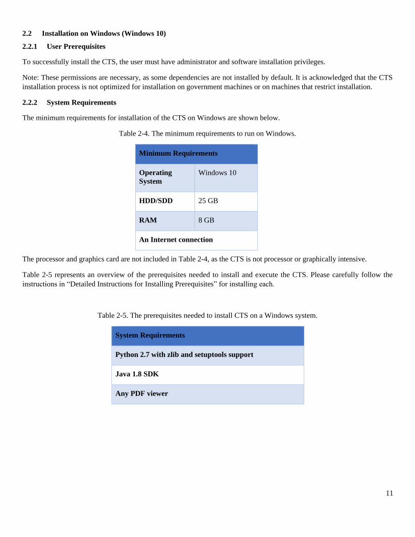
Table 2-4. The minimum requirements to run on Windows.
Minimum Requirements
Operating
System
Windows 10
HDD/SDD 25 GB
RAM 8 GB
An Internet connection
The processor and graphics card are not included in Table 2-4, as the CTS is not processor or graphically intensive.
Table 2-5 represents an overview of the prerequisites needed to install and execute the CTS. Please carefully follow the
instructions in “Detailed Instructions for Installing Prerequisites” for installing each.
Table 2-5. The prerequisites needed to install CTS on a Windows system.
System Requirements
Python 2.7 with zlib and setuptools support
Java 1.8 SDK
Any PDF viewer
12
2.2.3 Language-specific Prerequisites
The following section lists dependencies that UoCs written in a specific language require. The installation of each dependency
will be detailed in the “Detailed Instructions for Installing Prerequisites” for the user’s operating system, contained in this
document.
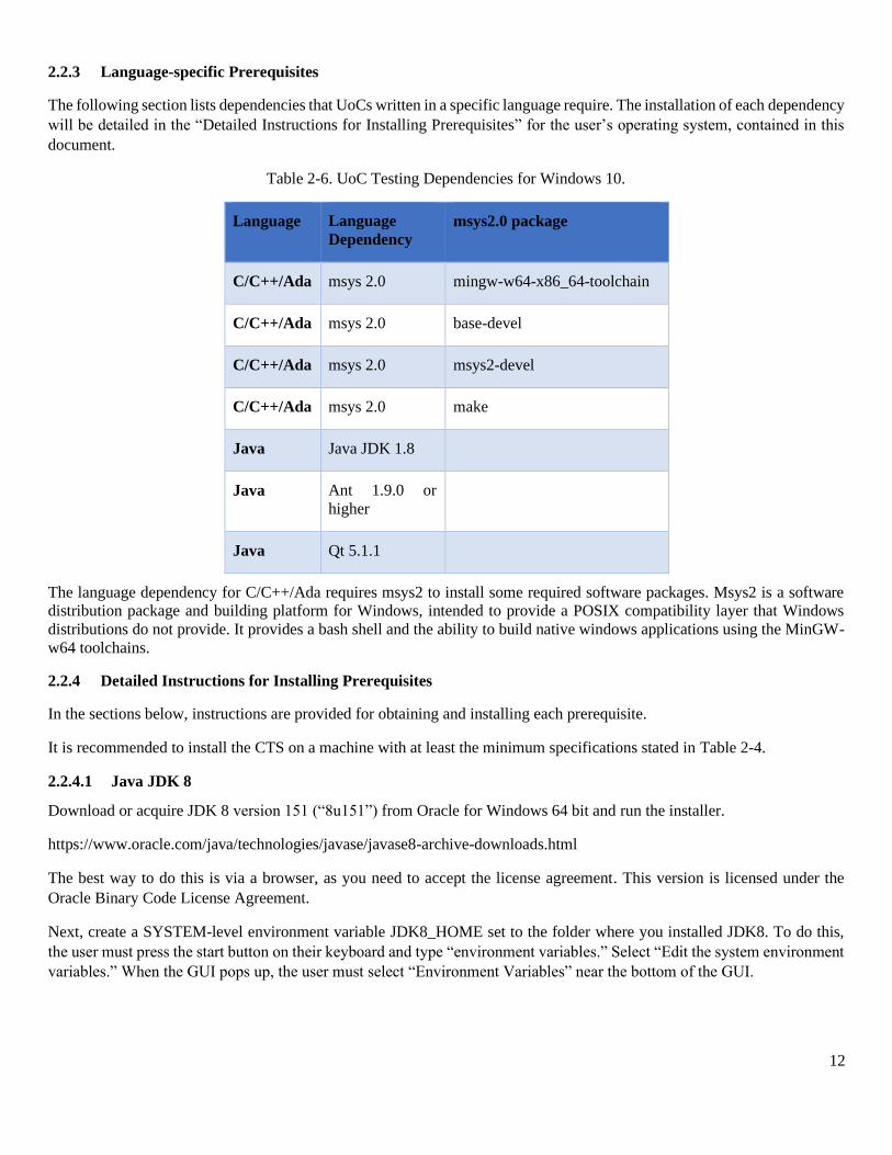
Table 2-6. UoC Testing Dependencies for Windows 10.
Language Language
Dependency
msys2.0 package
C/C++/Ada msys 2.0 mingw-w64-x86_64-toolchain
C/C++/Ada msys 2.0 base-devel
C/C++/Ada msys 2.0 msys2-devel
C/C++/Ada msys 2.0 make
Java Java JDK 1.8
Java Ant 1.9.0 or
higher
Java Qt 5.1.1
The language dependency for C/C++/Ada requires msys2 to install some required software packages. Msys2 is a software
distribution package and building platform for Windows, intended to provide a POSIX compatibility layer that Windows
distributions do not provide. It provides a bash shell and the ability to build native windows applications using the MinGW-
w64 toolchains.
2.2.4 Detailed Instructions for Installing Prerequisites
In the sections below, instructions are provided for obtaining and installing each prerequisite.
It is recommended to install the CTS on a machine with at least the minimum specifications stated in Table 2-4.
2.2.4.1 Java JDK 8
Download or acquire JDK 8 version 151 (“8u151”) from Oracle for Windows 64 bit and run the installer.
https://www.oracle.com/java/technologies/javase/javase8-archive-downloads.html
The best way to do this is via a browser, as you need to accept the license agreement. This version is licensed under the
Oracle Binary Code License Agreement.
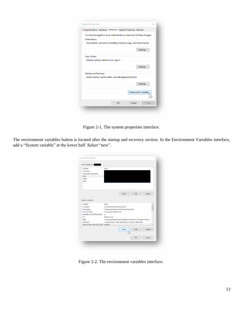
Next, create a SYSTEM-level environment variable JDK8_HOME set to the folder where you installed JDK8. To do this,
the user must press the start button on their keyboard and type “environment variables.” Select “Edit the system environment
variables.” When the GUI pops up, the user must select “Environment Variables” near the bottom of the GUI.
13
The environment variables button is located after the startup and recovery section. In the Environment Variables interface,
add a “System variable” at the lower half. Select “new”.
Figure 2-1. The system properties interface.
Figure 2-2. The environment variables interface.
14
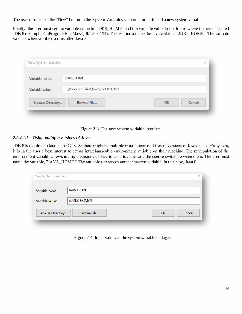
The user must select the "New" button in the System Variables section in order to add a new system variable.
Finally, the user must set the variable name to ‘JDK8_HOME’ and the variable value to the folder where the user installed
JDK 8 (example: C:\Program Files\Java\jdk1.8.0_151). The user must name the Java variable, "JDK8_HOME." The variable
value is wherever the user installed Java 8.
Figure 2-3. The new system variable interface.
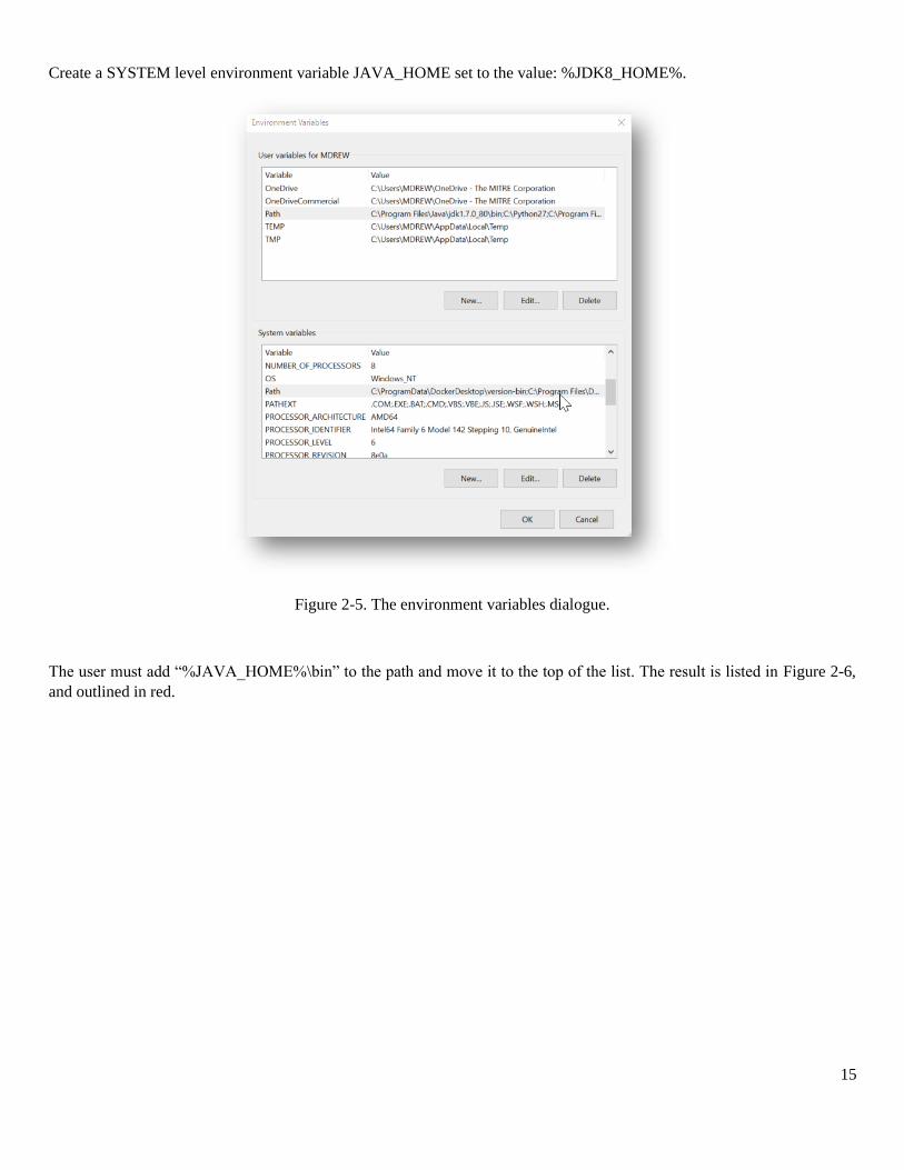
2.2.4.1.1 Using multiple versions of Java
JDK 8 is required to launch the CTS. As there might be multiple installations of different versions of Java on a user’s system,
it is in the user’s best interest to set an interchangeable environment variable on their machine. The manipulation of the
environment variable allows multiple versions of Java to exist together and the user to switch between them. The user must
name the variable, "JAVA_HOME." The variable references another system variable. In this case, Java 8.
Figure 2-4. Input values in the system variable dialogue.
15
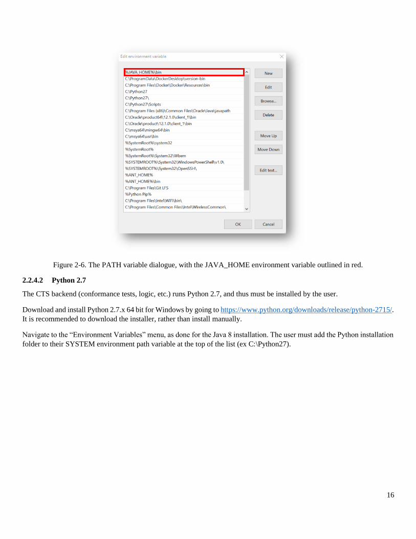
Create a SYSTEM level environment variable JAVA_HOME set to the value: %JDK8_HOME%.
Figure 2-5. The environment variables dialogue.
The user must add “%JAVA_HOME%\bin” to the path and move it to the top of the list. The result is listed in Figure 2-6,
and outlined in red.
16
Figure 2-6. The PATH variable dialogue, with the JAVA_HOME environment variable outlined in red.
2.2.4.2 Python 2.7
The CTS backend (conformance tests, logic, etc.) runs Python 2.7, and thus must be installed by the user.
Download and install Python 2.7.x 64 bit for Windows by going to https://www.python.org/downloads/release/python-2715/.
It is recommended to download the installer, rather than install manually.
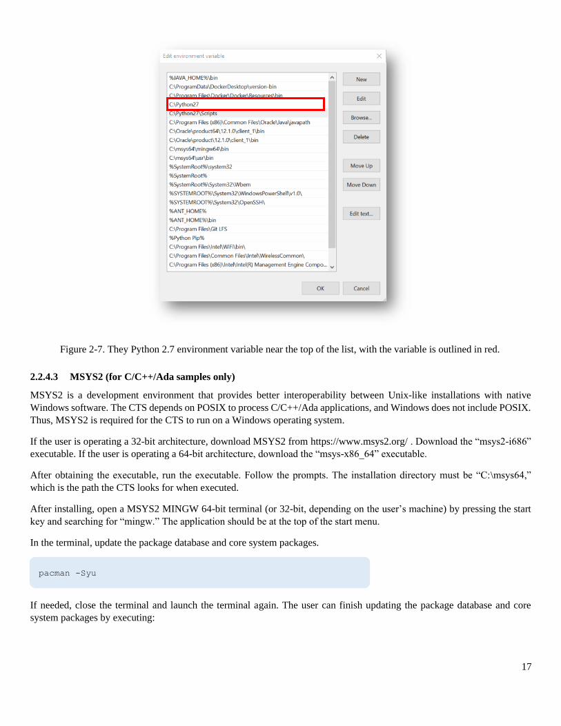
Navigate to the “Environment Variables” menu, as done for the Java 8 installation. The user must add the Python installation
folder to their SYSTEM environment path variable at the top of the list (ex C:\Python27).
17
2.2.4.3 MSYS2 (for C/C++/Ada samples only)
MSYS2 is a development environment that provides better interoperability between Unix-like installations with native
Windows software. The CTS depends on POSIX to process C/C++/Ada applications, and Windows does not include POSIX.
Thus, MSYS2 is required for the CTS to run on a Windows operating system.
If the user is operating a 32-bit architecture, download MSYS2 from https://www.msys2.org/ . Download the “msys2-i686”
executable. If the user is operating a 64-bit architecture, download the “msys-x86_64” executable.
After obtaining the executable, run the executable. Follow the prompts. The installation directory must be “C:\msys64,”
which is the path the CTS looks for when executed.
After installing, open a MSYS2 MINGW 64-bit terminal (or 32-bit, depending on the user’s machine) by pressing the start
key and searching for “mingw.” The application should be at the top of the start menu.
In the terminal, update the package database and core system packages.
If needed, close the terminal and launch the terminal again. The user can finish updating the package database and core
system packages by executing:
Figure 2-7. They Python 2.7 environment variable near the top of the list, with the variable is outlined in red.
pacman -Syu
18
If there are additional problems with the initial MSYS2 installation, it is recommended to consult the MSYS2 detailed
installation guide at https://github.com/msys2/msys2/wiki/MSYS2-installation.
Install several additional required packages via pacman:
The user will be prompted to select configuration for the packages that pacman was asked to install. Select “default - install
all,” and confirm with “Y”.
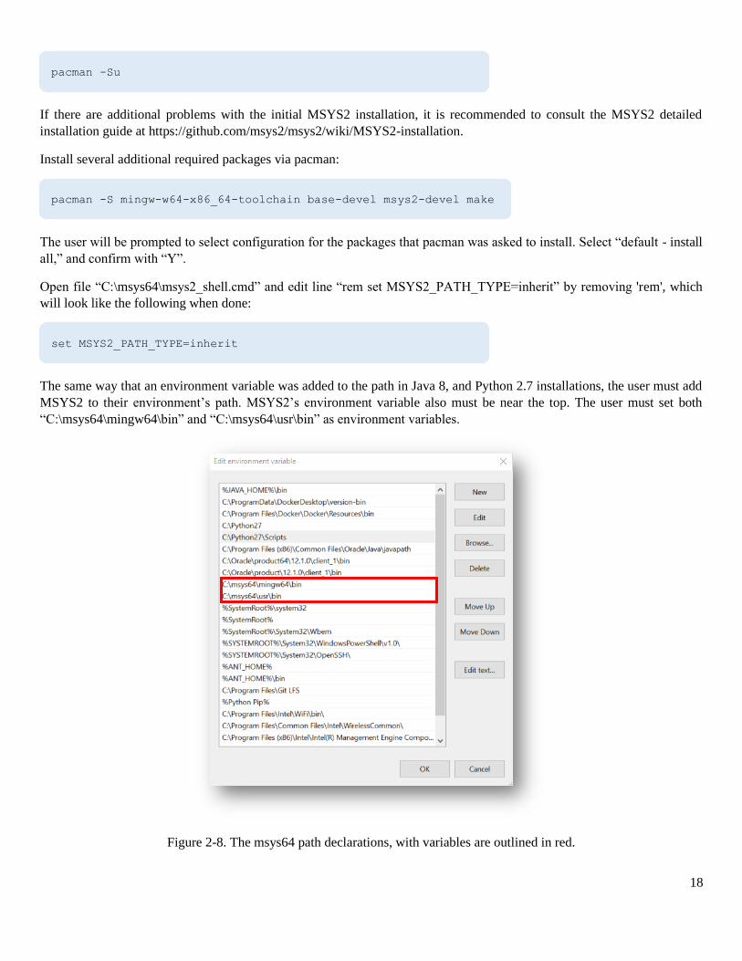
Open file “C:\msys64\msys2_shell.cmd” and edit line “rem set MSYS2_PATH_TYPE=inherit” by removing 'rem', which
will look like the following when done:
The same way that an environment variable was added to the path in Java 8, and Python 2.7 installations, the user must add
MSYS2 to their environment’s path. MSYS2’s environment variable also must be near the top. The user must set both
“C:\msys64\mingw64\bin” and “C:\msys64\usr\bin” as environment variables.
Figure 2-8. The msys64 path declarations, with variables are outlined in red.
pacman -Su
pacman -S mingw-w64-x86_64-toolchain base-devel msys2-devel make
set MSYS2_PATH_TYPE=inherit
19
2.2.4.4 Ant 1.9.x
Download the binary installer for Apache Ant 1.9.x from the Apache website:
https://ant.apache.org/bindownload.cgi
Extract the binary zip file contents to “C:\Program Files\”. This should create a folder such as “C:\Program Files\apache-ant-
1.9.9” (depending on exact version of 1.9.x that is downloaded). Ant is precompiled, and no installer needs to be run to have
Ant properly work.
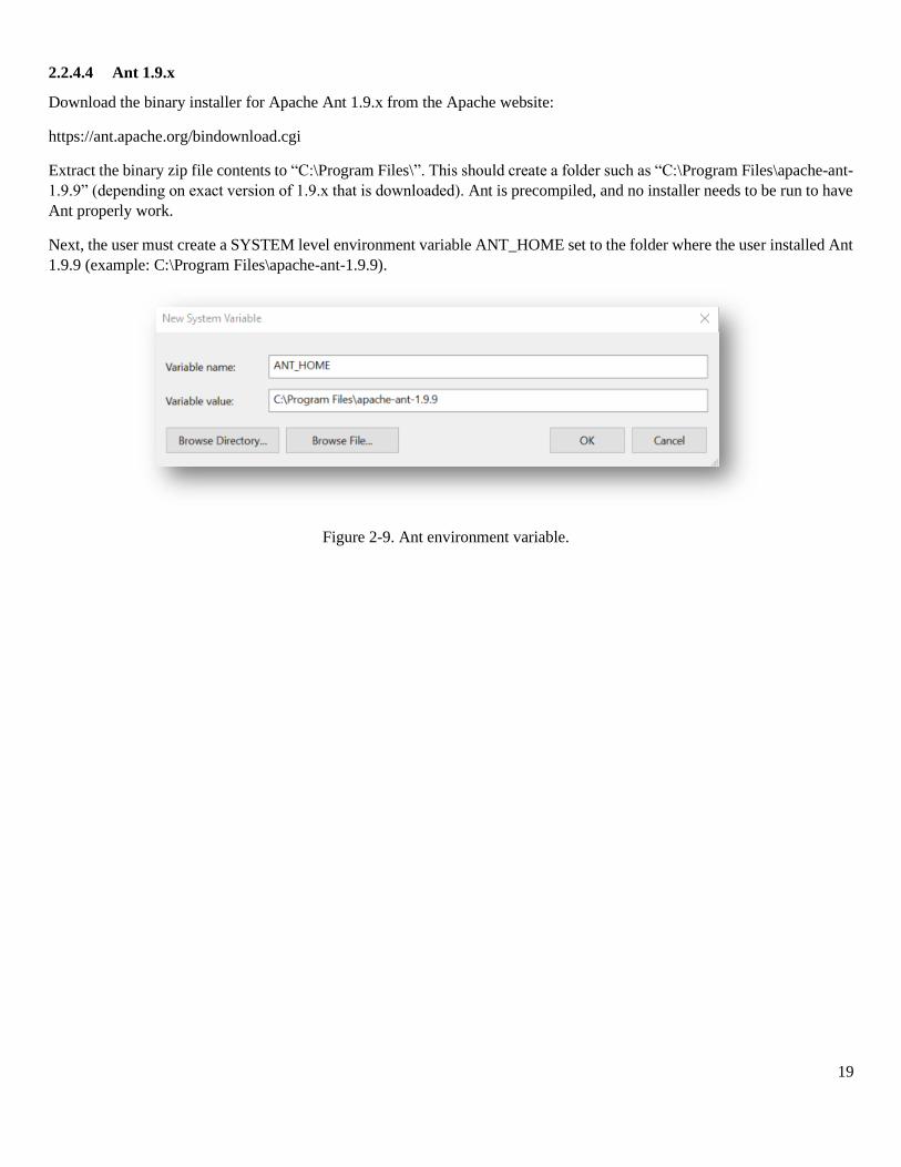
Next, the user must create a SYSTEM level environment variable ANT_HOME set to the folder where the user installed Ant
1.9.9 (example: C:\Program Files\apache-ant-1.9.9).
Figure 2-9. Ant environment variable.
20
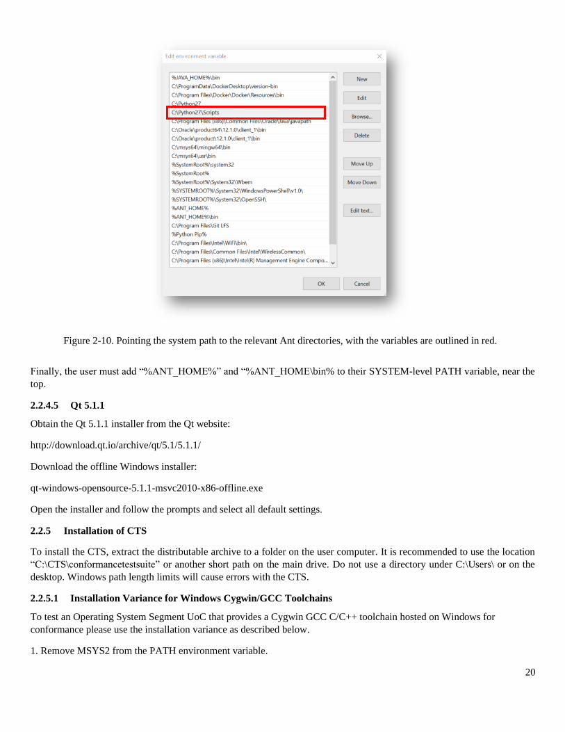
Finally, the user must add “%ANT_HOME%” and “%ANT_HOME\bin% to their SYSTEM-level PATH variable, near the
top.
2.2.4.5 Qt 5.1.1
Obtain the Qt 5.1.1 installer from the Qt website:
http://download.qt.io/archive/qt/5.1/5.1.1/
Download the offline Windows installer:
qt-windows-opensource-5.1.1-msvc2010-x86-offline.exe
Open the installer and follow the prompts and select all default settings.
2.2.5 Installation of CTS
To install the CTS, extract the distributable archive to a folder on the user computer. It is recommended to use the location
“C:\CTS\conformancetestsuite” or another short path on the main drive. Do not use a directory under C:\Users\ or on the
desktop. Windows path length limits will cause errors with the CTS.
2.2.5.1 Installation Variance for Windows Cygwin/GCC Toolchains
To test an Operating System Segment UoC that provides a Cygwin GCC C/C++ toolchain hosted on Windows for
conformance please use the installation variance as described below.
1. Remove MSYS2 from the PATH environment variable.
Figure 2-10. Pointing the system path to the relevant Ant directories, with the variables are outlined in red.
21
• C:\msys64\mingw64\bin
• C:\msys64\usr\bin
2. Add Cygwin as bundled in the product to the PATH environment variable.
• %CYGHOME%\bin, where %CYGHOME% is the full path to the root Cygwin directory.
Start CTS from the command line, rather than the installed desktop icon that invokes an MSYS2 shell script. The
instructions are documented in Test Suite Command Line Options section of this document.
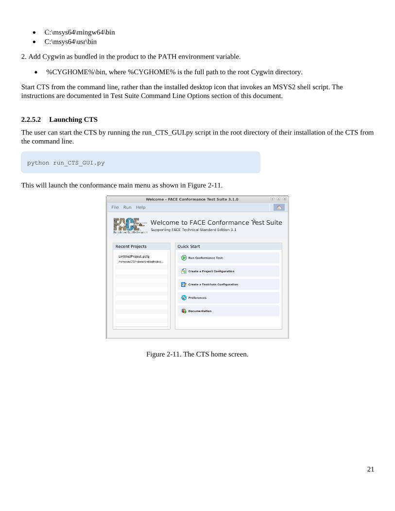
2.2.5.2 Launching CTS
The user can start the CTS by running the run_CTS_GUI.py script in the root directory of their installation of the CTS from
the command line.
This will launch the conformance main menu as shown in Figure 2-11.
python run_CTS_GUI.py
Figure 2-11. The CTS home screen.
22
3 Building the Sample Projects and Toolchains
Optionally, the user may generate CTS-provided sample projects and generate toolchain files using an included python script.
These must be generated using the testUtility.py script, found in the [root directory of CTS]/sample directory.
Sample projects and toolchains are provided for each FACE segment.
• For TSS segments, the UoC name is assumed to be "UOPName."
• For IOSS segments, the UoC name is assumed to be "UOPName."
• For PCS, the UoP name is taken from the sample data model and is set to "UoP1"
• For PSSS, the UoP name is "UoP2" (also per the sample data model).
Folders under the 'sample' directory are as follows:
• projects - contains sample projects for all languages.
• toolchains - sample toolchains.
• datamodels - sample data model used by sample projects.
3.1 Build Flags
Generating all samples at once may not be feasible for the user. Luckily, the testUtility.py script allows for flags that delimit
sample generation based on language, profile, FACE segment, and others.
To avoid longer build times, it is recommended that the user may want to set their build flags to build one language at a time
(“-c”, “-p”, “-a”, and “-j”).
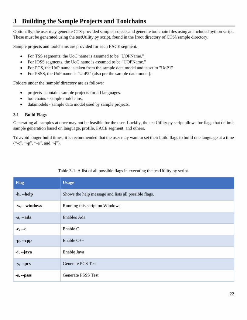
Table 3-1. A list of all possible flags in executing the testUtility.py script.
Flag Usage
-h, --help Shows the help message and lists all possible flags.
-w, --windows Running this script on Windows
-a, --ada Enables Ada
-c, --c Enable C
-p, --cpp Enable C++
-j, --java Enable Java
-y, --pcs Generate PCS Test
-s, --psss Generate PSSS Test
23
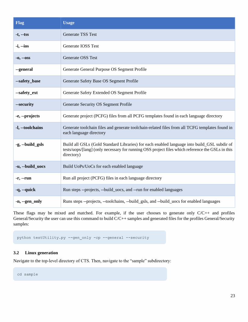
Flag Usage
-t, --tss Generate TSS Test
-i, --ios Generate IOSS Test
-o, --oss Generate OSS Test
--general Generate General Purpose OS Segment Profile
--safety_base Generate Safety Base OS Segment Profile
--safety_ext Generate Safety Extended OS Segment Profile
--security Generate Security OS Segment Profile
-e, --projects Generate project (PCFG) files from all PCFG templates found in each language directory
-l, --toolchains Generate toolchain files and generate toolchain-related files from all TCFG templates found in
each language directory
-g, --build_gsls Build all GSLs (Gold Standard Libraries) for each enabled language into build_GSL subdir of
tests/uops/[lang] (only necessary for running OSS project files which reference the GSLs in this
directory)
-u, --build_uocs Build UoPs/UoCs for each enabled language
-r, --run Run all project (PCFG) files in each language directory
-q, --quick Run steps --projects, --build_uocs, and --run for enabled languages
-n, --gen_only Runs steps --projects, --toolchains, --build_gsls, and --build_uocs for enabled languages
These flags may be mixed and matched. For example, if the user chooses to generate only C/C++ and profiles
General/Security the user can use this command to build C/C++ samples and generated files for the profiles General/Security
samples:
3.2 Linux generation
Navigate to the top-level directory of CTS. Then, navigate to the “sample” subdirectory:
python testUtility.py --gen_only -cp --general --security
cd sample
24
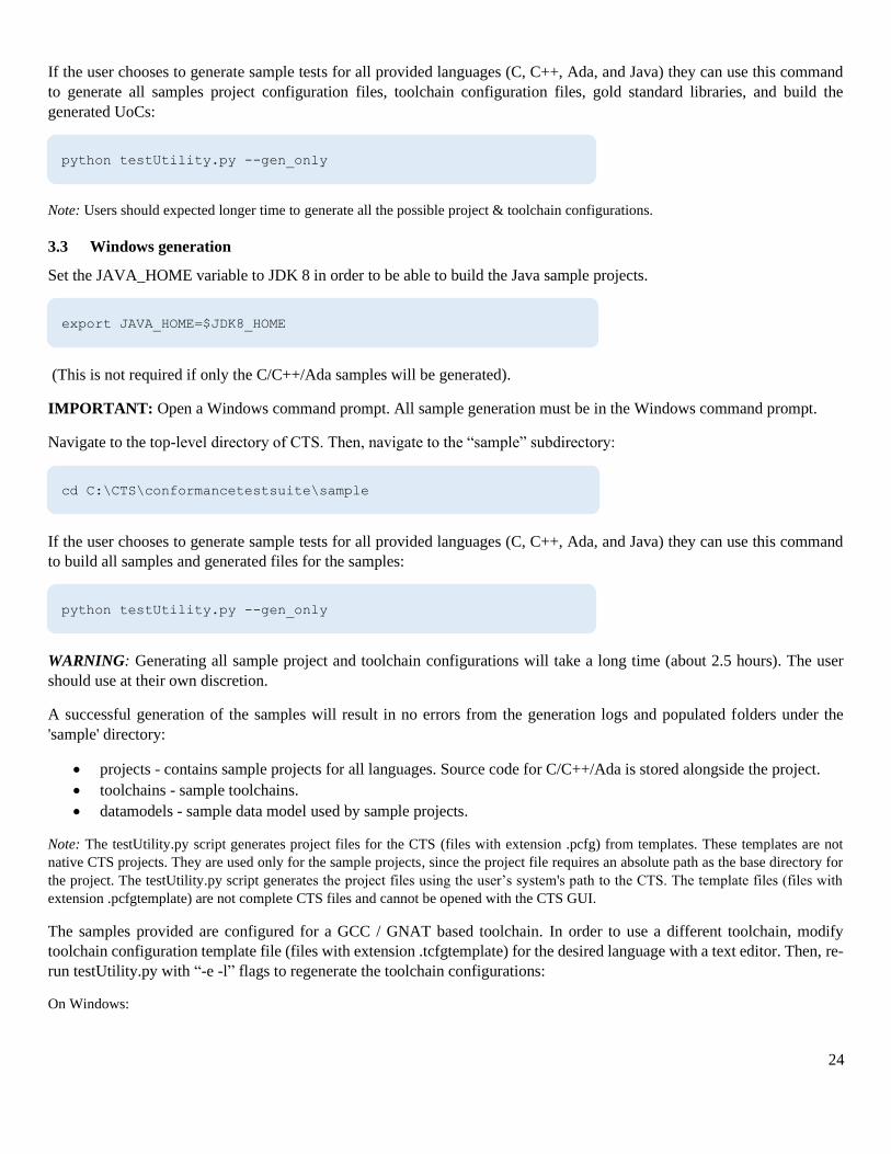
If the user chooses to generate sample tests for all provided languages (C, C++, Ada, and Java) they can use this command
to generate all samples project configuration files, toolchain configuration files, gold standard libraries, and build the
generated UoCs:
Note: Users should expected longer time to generate all the possible project & toolchain configurations.
3.3 Windows generation
Set the JAVA_HOME variable to JDK 8 in order to be able to build the Java sample projects.
(This is not required if only the C/C++/Ada samples will be generated).
IMPORTANT: Open a Windows command prompt. All sample generation must be in the Windows command prompt.
Navigate to the top-level directory of CTS. Then, navigate to the “sample” subdirectory:
If the user chooses to generate sample tests for all provided languages (C, C++, Ada, and Java) they can use this command
to build all samples and generated files for the samples:
WARNING: Generating all sample project and toolchain configurations will take a long time (about 2.5 hours). The user
should use at their own discretion.
A successful generation of the samples will result in no errors from the generation logs and populated folders under the
'sample' directory:
• projects - contains sample projects for all languages. Source code for C/C++/Ada is stored alongside the project.
• toolchains - sample toolchains.
• datamodels - sample data model used by sample projects.
Note: The testUtility.py script generates project files for the CTS (files with extension .pcfg) from templates. These templates are not
native CTS projects. They are used only for the sample projects, since the project file requires an absolute path as the base directory for
the project. The testUtility.py script generates the project files using the user’s system's path to the CTS. The template files (files with
extension .pcfgtemplate) are not complete CTS files and cannot be opened with the CTS GUI.
The samples provided are configured for a GCC / GNAT based toolchain. In order to use a different toolchain, modify
toolchain configuration template file (files with extension .tcfgtemplate) for the desired language with a text editor. Then, re-
run testUtility.py with “-e -l” flags to regenerate the toolchain configurations:
On Windows:
python testUtility.py --gen_only
export JAVA_HOME=$JDK8_HOME
cd C:\CTS\conformancetestsuite\sample
python testUtility.py --gen_only
25
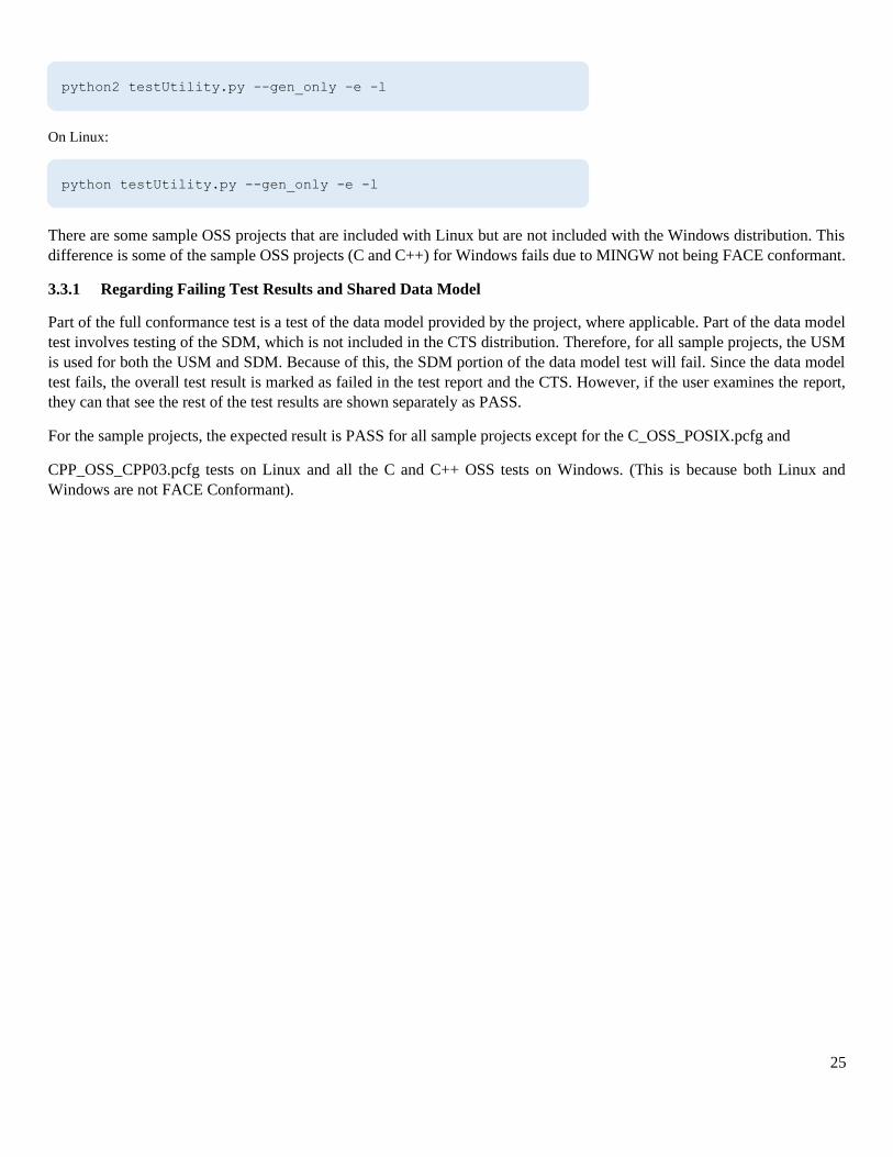
On Linux:
There are some sample OSS projects that are included with Linux but are not included with the Windows distribution. This
difference is some of the sample OSS projects (C and C++) for Windows fails due to MINGW not being FACE conformant.
3.3.1 Regarding Failing Test Results and Shared Data Model
Part of the full conformance test is a test of the data model provided by the project, where applicable. Part of the data model
test involves testing of the SDM, which is not included in the CTS distribution. Therefore, for all sample projects, the USM
is used for both the USM and SDM. Because of this, the SDM portion of the data model test will fail. Since the data model
test fails, the overall test result is marked as failed in the test report and the CTS. However, if the user examines the report,
they can that see the rest of the test results are shown separately as PASS.
For the sample projects, the expected result is PASS for all sample projects except for the C_OSS_POSIX.pcfg and
CPP_OSS_CPP03.pcfg tests on Linux and all the C and C++ OSS tests on Windows. (This is because both Linux and
Windows are not FACE Conformant).
python2 testUtility.py --gen_only -e -l
python testUtility.py --gen_only -e -l
26
4 Theory of Operation
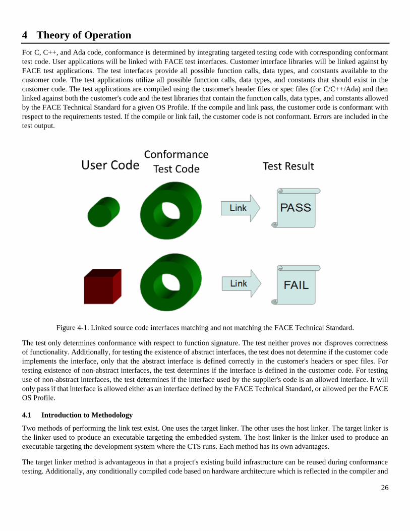
For C, C++, and Ada code, conformance is determined by integrating targeted testing code with corresponding conformant
test code. User applications will be linked with FACE test interfaces. Customer interface libraries will be linked against by
FACE test applications. The test interfaces provide all possible function calls, data types, and constants available to the
customer code. The test applications utilize all possible function calls, data types, and constants that should exist in the
customer code. The test applications are compiled using the customer's header files or spec files (for C/C++/Ada) and then
linked against both the customer's code and the test libraries that contain the function calls, data types, and constants allowed
by the FACE Technical Standard for a given OS Profile. If the compile and link pass, the customer code is conformant with
respect to the requirements tested. If the compile or link fail, the customer code is not conformant. Errors are included in the
test output.
Figure 4-1. Linked source code interfaces matching and not matching the FACE Technical Standard.
The test only determines conformance with respect to function signature. The test neither proves nor disproves correctness
of functionality. Additionally, for testing the existence of abstract interfaces, the test does not determine if the customer code
implements the interface, only that the abstract interface is defined correctly in the customer's headers or spec files. For
testing existence of non-abstract interfaces, the test determines if the interface is defined in the customer code. For testing
use of non-abstract interfaces, the test determines if the interface used by the supplier's code is an allowed interface. It will
only pass if that interface is allowed either as an interface defined by the FACE Technical Standard, or allowed per the FACE
OS Profile.
4.1 Introduction to Methodology
Two methods of performing the link test exist. One uses the target linker. The other uses the host linker. The target linker is
the linker used to produce an executable targeting the embedded system. The host linker is the linker used to produce an
executable targeting the development system where the CTS runs. Each method has its own advantages.
The target linker method is advantageous in that a project's existing build infrastructure can be reused during conformance
testing. Additionally, any conditionally compiled code based on hardware architecture which is reflected in the compiler and
27
linker will be included in the conformance testing. The disadvantage is that conformance testing authority must know the
details of the target linker.
The host linker is advantageous in that its usage details are preselected in the conformance tool. Its disadvantage is that
conditionally compiled code based on hardware architecture which is reflected in the compiler and linker may not be included
in conformance testing. Additionally, the project's build infrastructure would need to be modified to make use of the host
compiler and linker.
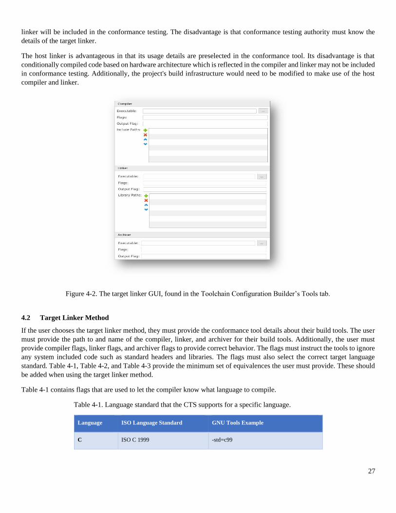
4.2 Target Linker Method
If the user chooses the target linker method, they must provide the conformance tool details about their build tools. The user
must provide the path to and name of the compiler, linker, and archiver for their build tools. Additionally, the user must
provide compiler flags, linker flags, and archiver flags to provide correct behavior. The flags must instruct the tools to ignore
any system included code such as standard headers and libraries. The flags must also select the correct target language
standard. Table 4-1, Table 4-2, and Table 4-3 provide the minimum set of equivalences the user must provide. These should
be added when using the target linker method.
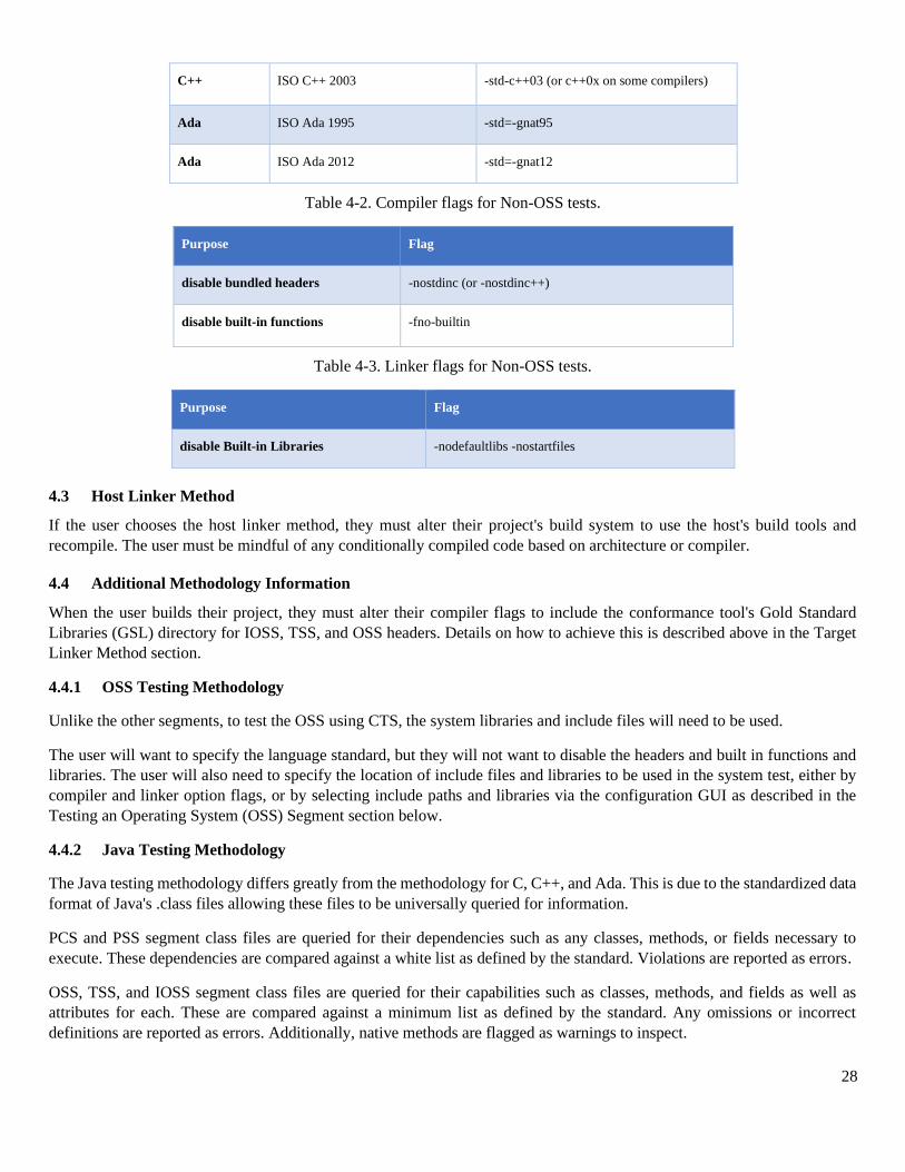
Table 4-1 contains flags that are used to let the compiler know what language to compile.
Table 4-1. Language standard that the CTS supports for a specific language.
Language ISO Language Standard GNU Tools Example
C ISO C 1999 -std=c99
Figure 4-2. The target linker GUI, found in the Toolchain Configuration Builder’s Tools tab.
28
C++ ISO C++ 2003 -std-c++03 (or c++0x on some compilers)
Ada ISO Ada 1995 -std=-gnat95
Ada ISO Ada 2012 -std=-gnat12
Table 4-2. Compiler flags for Non-OSS tests.
Purpose Flag
disable bundled headers -nostdinc (or -nostdinc++)
disable built-in functions -fno-builtin
Table 4-3. Linker flags for Non-OSS tests.
Purpose Flag
disable Built-in Libraries -nodefaultlibs -nostartfiles
4.3 Host Linker Method
If the user chooses the host linker method, they must alter their project's build system to use the host's build tools and
recompile. The user must be mindful of any conditionally compiled code based on architecture or compiler.
4.4 Additional Methodology Information
When the user builds their project, they must alter their compiler flags to include the conformance tool's Gold Standard
Libraries (GSL) directory for IOSS, TSS, and OSS headers. Details on how to achieve this is described above in the Target
Linker Method section.
4.4.1 OSS Testing Methodology
Unlike the other segments, to test the OSS using CTS, the system libraries and include files will need to be used.
The user will want to specify the language standard, but they will not want to disable the headers and built in functions and
libraries. The user will also need to specify the location of include files and libraries to be used in the system test, either by
compiler and linker option flags, or by selecting include paths and libraries via the configuration GUI as described in the
Testing an Operating System (OSS) Segment section below.
4.4.2 Java Testing Methodology
The Java testing methodology differs greatly from the methodology for C, C++, and Ada. This is due to the standardized data
format of Java's .class files allowing these files to be universally queried for information.
PCS and PSS segment class files are queried for their dependencies such as any classes, methods, or fields necessary to
execute. These dependencies are compared against a white list as defined by the standard. Violations are reported as errors.
OSS, TSS, and IOSS segment class files are queried for their capabilities such as classes, methods, and fields as well as
attributes for each. These are compared against a minimum list as defined by the standard. Any omissions or incorrect
definitions are reported as errors. Additionally, native methods are flagged as warnings to inspect.
29
5 Toolchain Configuration Files
5.1 Introduction
A toolchain configuration file (TCFG, .tcfg, toolchain file, toolchain) contains information to configure and compile CTS-
test objects. A toolchain configuration file also contains information about how to link with a user supplied UoC, given the
UoC target environment. This information provides an environment where the CTS can configure the correct environment to
use information stored in the Project Configuration file. The toolchain configuration file ending is .tcfg.
Toolchain configuration files are generated with string template (http://www.stringtemplate.org/), a freely available template
library for generating source code.
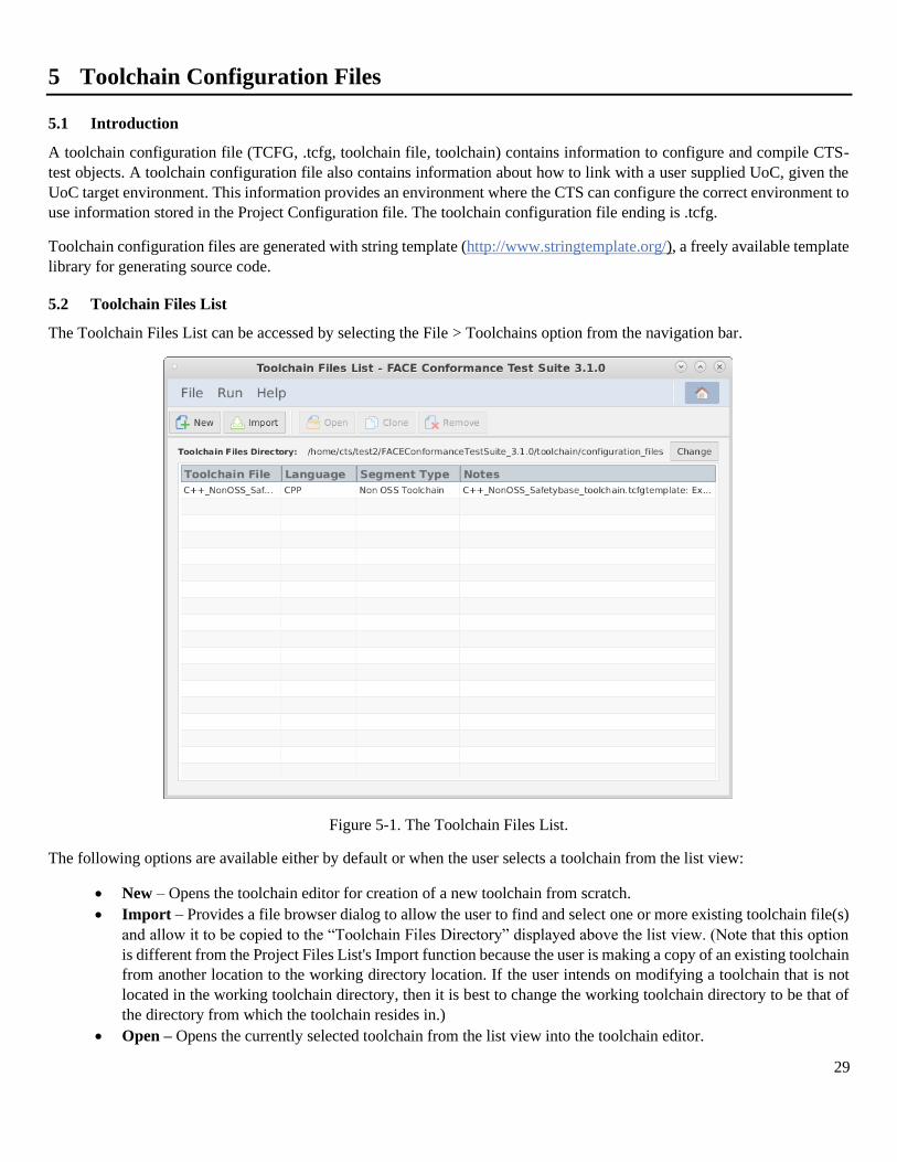
5.2 Toolchain Files List
The Toolchain Files List can be accessed by selecting the File > Toolchains option from the navigation bar.
Figure 5-1. The Toolchain Files List.
The following options are available either by default or when the user selects a toolchain from the list view:
• New – Opens the toolchain editor for creation of a new toolchain from scratch.
• Import – Provides a file browser dialog to allow the user to find and select one or more existing toolchain file(s)
and allow it to be copied to the “Toolchain Files Directory” displayed above the list view. (Note that this option
is different from the Project Files List's Import function because the user is making a copy of an existing toolchain
from another location to the working directory location. If the user intends on modifying a toolchain that is not
located in the working toolchain directory, then it is best to change the working toolchain directory to be that of
the directory from which the toolchain resides in.)
• Open – Opens the currently selected toolchain from the list view into the toolchain editor.
30
• Remove – Removes the currently selected toolchain from the list view. (Note that this option does not delete the
toolchain, but removes it from the list view only.)
• Clone – Creates a copy of the currently selected toolchain and saves it to the “Toolchain Files Directory”.
• Change – This opens a directory browser dialog to allow the user to change the directory to search for and display
all available toolchains in this toolchain list view.
Further, the user may define a “Toolchain Files Directory”, a directory for the CTS to detect TCFG files to automatically
import into the toolchain file list.
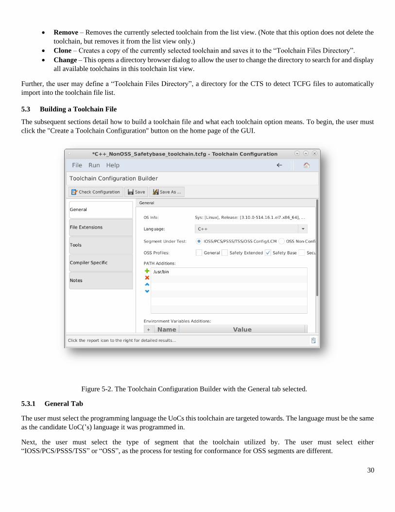
5.3 Building a Toolchain File
The subsequent sections detail how to build a toolchain file and what each toolchain option means. To begin, the user must
click the "Create a Toolchain Configuration" button on the home page of the GUI.
5.3.1 General Tab
The user must select the programming language the UoCs this toolchain are targeted towards. The language must be the same
as the candidate UoC(’s) language it was programmed in.
Next, the user must select the type of segment that the toolchain utilized by. The user must select either
“IOSS/PCS/PSSS/TSS” or “OSS”, as the process for testing for conformance for OSS segments are different.
Figure 5-2. The Toolchain Configuration Builder with the General tab selected.
31
The user must then define the OSS profile(s) that the candidate UoC(s) satisfy. There may be more than one profile that is
supported by a UoC, and the user must select all that are applicable.
The “PATH addition” section allows the user to include any libraries a UoC may need while being built or archived. The
user may add file paths that include these library locations. For example, on Linux-based systems if the user has installed
gcc, including “/usr/bin”, it is required to allow the toolchain to recognize the path of the compiler.
The “Environment Variables Additions” section allows the user to define an environment variable name and value. In the
sample projects that are generated by the CTS, the environment variables are “dummy” and “hello” with values “123” and “
world,” respectively.
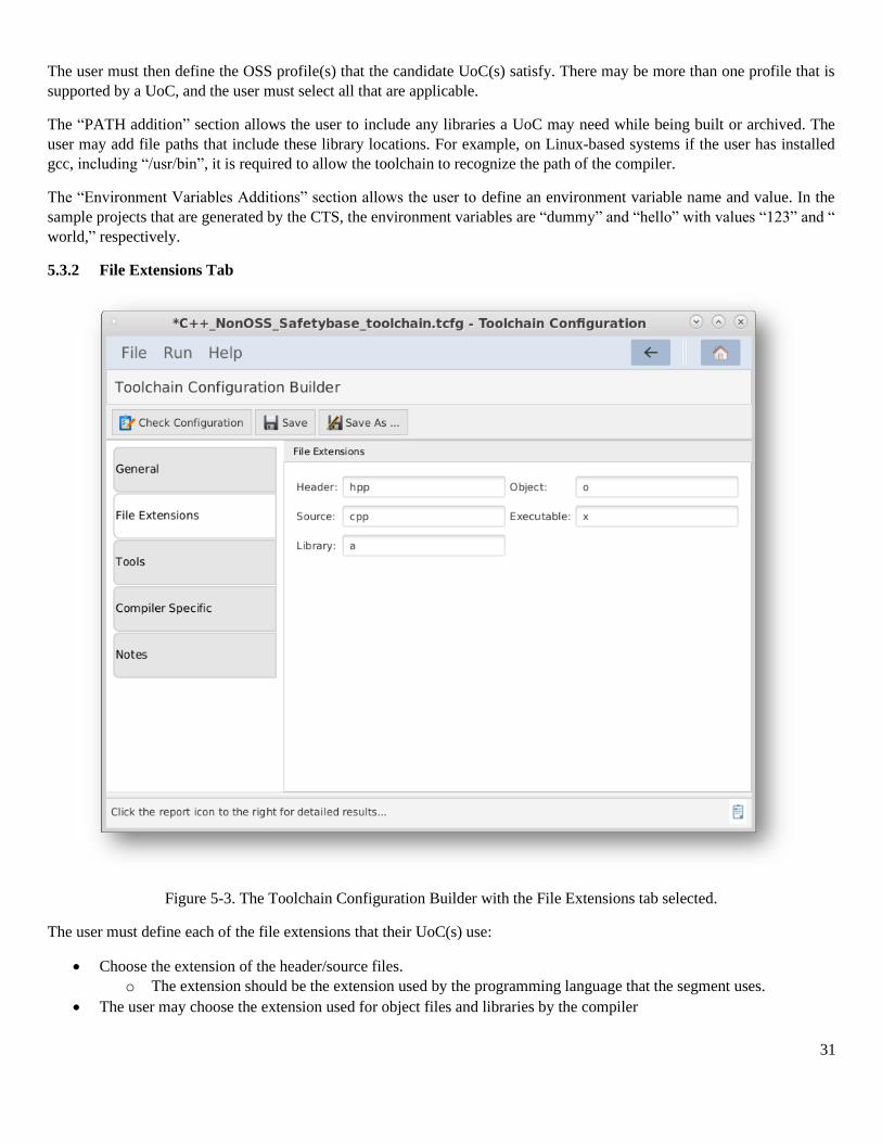
5.3.2 File Extensions Tab
Figure 5-3. The Toolchain Configuration Builder with the File Extensions tab selected.
The user must define each of the file extensions that their UoC(s) use:
• Choose the extension of the header/source files.
o The extension should be the extension used by the programming language that the segment uses.
• The user may choose the extension used for object files and libraries by the compiler
32
The user may choose to include the extension used for executable files by the compiler. (Leave blank for no
extension.)
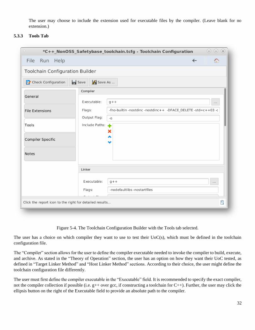
5.3.3 Tools Tab
Figure 5-4. The Toolchain Configuration Builder with the Tools tab selected.
The user has a choice on which compiler they want to use to test their UoC(s), which must be defined in the toolchain
configuration file.
The “Compiler” section allows for the user to define the compiler executable needed to invoke the compiler to build, execute,
and archive. As stated in the “Theory of Operation” section, the user has an option on how they want their UoC tested, as
defined in “Target Linker Method” and “Host Linker Method” sections. According to their choice, the user might define the
toolchain configuration file differently.
The user must first define the compiler executable in the “Executable” field. It is recommended to specify the exact compiler,
not the compiler collection if possible (i.e. g++ over gcc, if constructing a toolchain for C++). Further, the user may click the
ellipsis button on the right of the Executable field to provide an absolute path to the compiler.
33
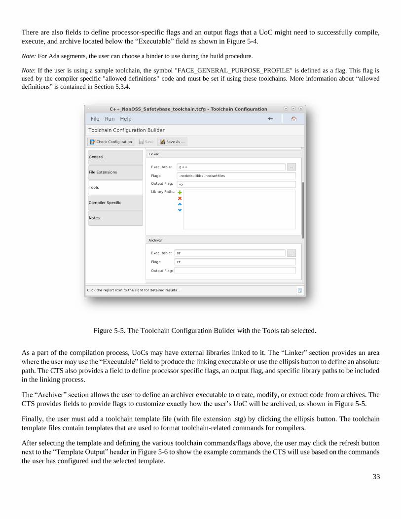
There are also fields to define processor-specific flags and an output flags that a UoC might need to successfully compile,
execute, and archive located below the “Executable” field as shown in Figure 5-4.
Note: For Ada segments, the user can choose a binder to use during the build procedure.
Note: If the user is using a sample toolchain, the symbol "FACE_GENERAL_PURPOSE_PROFILE" is defined as a flag. This flag is
used by the compiler specific "allowed definitions" code and must be set if using these toolchains. More information about “allowed
definitions” is contained in Section 5.3.4.
As a part of the compilation process, UoCs may have external libraries linked to it. The “Linker” section provides an area
where the user may use the “Executable” field to produce the linking executable or use the ellipsis button to define an absolute
path. The CTS also provides a field to define processor specific flags, an output flag, and specific library paths to be included
in the linking process.
The “Archiver” section allows the user to define an archiver executable to create, modify, or extract code from archives. The
CTS provides fields to provide flags to customize exactly how the user’s UoC will be archived, as shown in Figure 5-5.
Finally, the user must add a toolchain template file (with file extension .stg) by clicking the ellipsis button. The toolchain
template files contain templates that are used to format toolchain-related commands for compilers.
After selecting the template and defining the various toolchain commands/flags above, the user may click the refresh button
next to the “Template Output” header in Figure 5-6 to show the example commands the CTS will use based on the commands
the user has configured and the selected template.
Figure 5-5. The Toolchain Configuration Builder with the Tools tab selected.
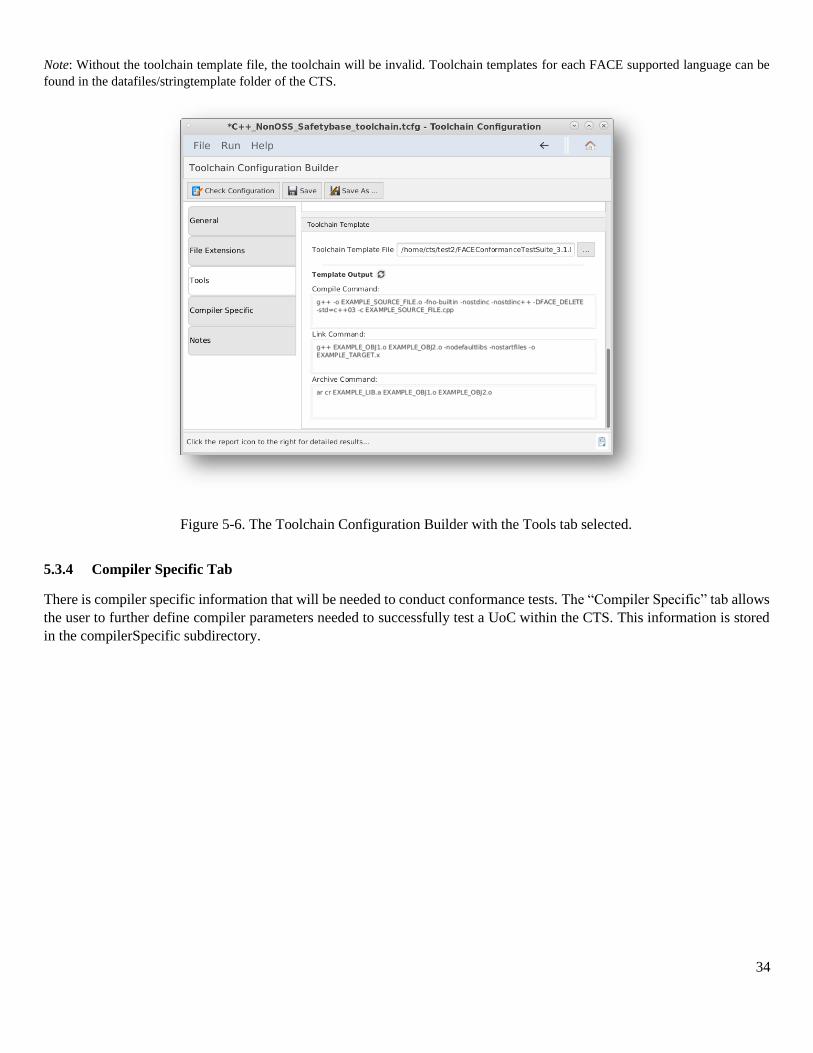
34
Note: Without the toolchain template file, the toolchain will be invalid. Toolchain templates for each FACE supported language can be
found in the datafiles/stringtemplate folder of the CTS.
5.3.4 Compiler Specific Tab
There is compiler specific information that will be needed to conduct conformance tests. The “Compiler Specific” tab allows
the user to further define compiler parameters needed to successfully test a UoC within the CTS. This information is stored
in the compilerSpecific subdirectory.
Figure 5-6. The Toolchain Configuration Builder with the Tools tab selected.
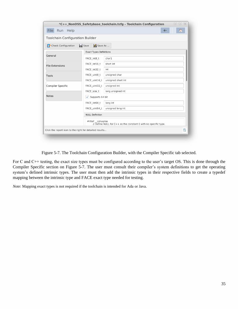
35
Figure 5-7. The Toolchain Configuration Builder, with the Compiler Specific tab selected.
For C and C++ testing, the exact size types must be configured according to the user’s target OS. This is done through the
Compiler Specific section on Figure 5-7. The user must consult their compiler’s system definitions to get the operating
system’s defined intrinsic types. The user must then add the intrinsic types in their respective fields to create a typedef
mapping between the intrinsic type and FACE exact type needed for testing.
Note: Mapping exact types is not required if the toolchain is intended for Ada or Java.
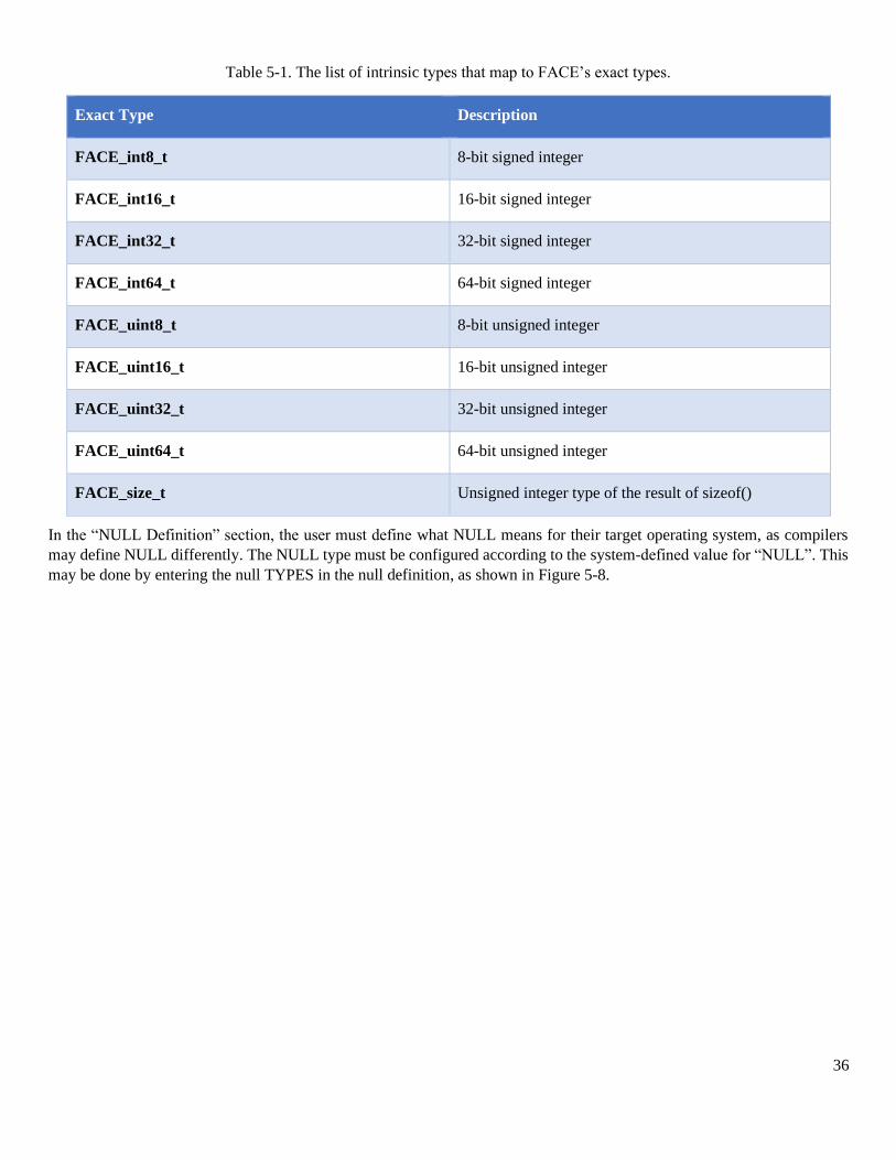
36
Table 5-1. The list of intrinsic types that map to FACE’s exact types.
Exact Type Description
FACE_int8_t 8-bit signed integer
FACE_int16_t 16-bit signed integer
FACE_int32_t 32-bit signed integer
FACE_int64_t 64-bit signed integer
FACE_uint8_t 8-bit unsigned integer
FACE_uint16_t 16-bit unsigned integer
FACE_uint32_t 32-bit unsigned integer
FACE_uint64_t 64-bit unsigned integer
FACE_size_t Unsigned integer type of the result of sizeof()
In the “NULL Definition” section, the user must define what NULL means for their target operating system, as compilers
may define NULL differently. The NULL type must be configured according to the system-defined value for “NULL”. This
may be done by entering the null TYPES in the null definition, as shown in Figure 5-8.
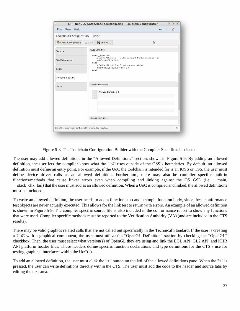
37
Figure 5-8. The Toolchain Configuration Builder with the Compiler Specific tab selected.
The user may add allowed definitions in the “Allowed Definitions” section, shown in Figure 5-9. By adding an allowed
definition, the user lets the compiler know what the UoC uses outside of the OSS’s boundaries. By default, an allowed
definition must define an entry point. For example, if the UoC the toolchain is intended for is an IOSS or TSS, the user must
define device driver calls as an allowed definition. Furthermore, there may also be compiler specific built-in
functions/methods that cause linker errors even when compiling and linking against the OS GSL (i.e. __main,
__stack_chk_fail) that the user must add as an allowed definition. When a UoC is compiled and linked, the allowed definitions
must be included.
To write an allowed definition, the user needs to add a function stub and a simple function body, since these conformance
test objects are never actually executed. This allows for the link test to return with errors. An example of an allowed definition
is shown in Figure 5-9. The compiler specific source file is also included in the conformance report to show any functions
that were used. Compiler specific methods must be reported to the Verification Authority (VA) (and are included in the CTS
results).
There may be valid graphics related calls that are not called out specifically in the Technical Standard. If the user is creating
a UoC with a graphical component, the user must utilize the “OpenGL Definition” section by checking the “OpenGL”
checkbox. Then, the user must select what version(s) of OpenGL they are using and link the EGL API, GL2 API, and KHR
API platform header files. These headers define specific function declarations and type definitions for the CTS’s use for
testing graphical interfaces within the UoC(s).
To add an allowed definition, the user must click the “+” button on the left of the allowed definitions pane. When the "+" is
pressed, the user can write definitions directly within the CTS. The user must add the code to the header and source tabs by
editing the text area.
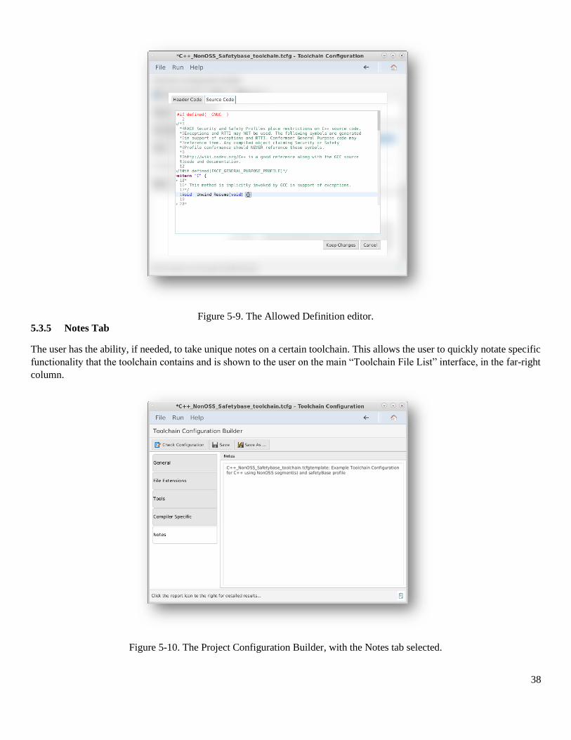
38
Figure 5-9. The Allowed Definition editor.
5.3.5 Notes Tab
The user has the ability, if needed, to take unique notes on a certain toolchain. This allows the user to quickly notate specific
functionality that the toolchain contains and is shown to the user on the main “Toolchain File List” interface, in the far-right
column.
Figure 5-10. The Project Configuration Builder, with the Notes tab selected.

39
6 Project Configuration Files
The project configuration file contains all UoC object paths, dependencies, and settings in order to accurately test a UoC for
conformance within the CTS. By defining a project configuration file within the CTS, a .pcfg file is created with the user’s
selected options. This .pcfg file is used by other tools contained in the CTS to test a UoC for conformance.
Figure 6-1. The Project Files List.
The Project Files List can be accessed by selecting the File from the navigation bar, and “Projects” from the dropdown. This
view represents a working sandbox view of project files that have been created or recently edited. Selecting a project from
this list view will provide access to the following options:
• New – Opens a new file dialog to create an empty project from scratch.
• Import – Provides a file browser dialog to allow the user to find an existing project file and allow it to be added
to the list view.
• Open – Opens the currently selected project from the list view.

40
• Remove – Removes the currently selected project from the list view. (Note that this option does not delete the
project but removes it from the list view only)
• Clone – Creates a copy of the currently selected project and saves it at the same location as the original
• Test Project – Executes the test procedure on the currently selected project.
6.1 Project Configuration Builder Interface
The following subsections detail each option available to the user in the Project Configuration builder. Sections 7.2 and 7.3
explain how to set the project configuration file for a specific UoC type (PCS, PSSS, TSS, IOSS, and OSS) through the CTS.
Unlike toolchain configuration files, one project configuration file is defined for every FACE UoC.
Upon opening a project configuration file within the CTS, the user will see the Project Configuration Builder interface.
6.1.1 General Tab
Figure 6-2. The Project Configuration Builder with the General tab selected.
For project configuration files to construct file paths, the user must define a base directory in the “Base Directory” field. All
files that are then selected within the project configuration file containing a relative path to the absolute file, based on this
base directory. For example, if the user declared their base directory to be “/home/user/CTS,” and decided wanted to select
a toolchain file located at /home/user/CTS/test-toolchain.tcfg, the toolchain path will be just “test-toolchain.tcfg.”
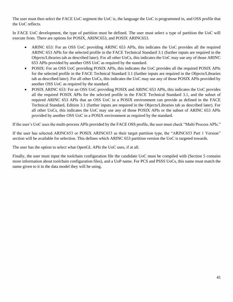
41
The user must then select the FACE UoC segment the UoC is, the language the UoC is programmed in, and OSS profile that
the UoC reflects.
In FACE UoC development, the type of partition must be defined. The user must select a type of partition the UoC will
execute from. There are options for POSIX, ARINC653, and POSIX ARINC653.
• ARINC 653: For an OSS UoC providing ARINC 653 APIs, this indicates the UoC provides all the required
ARINC 653 APIs for the selected profile in the FACE Technical Standard 3.1 (further inputs are required in the
Objects/Libraries tab as described later). For all other UoCs, this indicates the UoC may use any of those ARINC
653 APIs provided by another OSS UoC as required by the standard.
• POSIX: For an OSS UoC providing POSIX APIs, this indicates the UoC provides all the required POSIX APIs
for the selected profile in the FACE Technical Standard 3.1 (further inputs are required in the Objects/Libraries
tab as described later). For all other UoCs, this indicates the UoC may use any of those POSIX APIs provided by
another OSS UoC as required by the standard.
• POSIX ARINC 653: For an OSS UoC providing POSIX and ARINC 653 APIs, this indicates the UoC provides
all the required POSIX APIs for the selected profile in the FACE Technical Standard 3.1, and the subset of
required ARINC 653 APIs that an OSS UoC in a POSIX environment can provide as defined in the FACE
Technical Standard, Edition 3.1 (further inputs are required in the Objects/Libraries tab as described later). For
all other UoCs, this indicates the UoC may use any of those POSIX APIs or the subset of ARINC 653 APIs
provided by another OSS UoC in a POSIX environment as required by the standard.
If the user’s UoC uses the multi-process APIs provided by the FACE OSS profile, the user must check “Multi Process APIs.”
If the user has selected ARINC653 or POSIX ARINC653 as their target partition type, the “ARINC653 Part 1 Version”
section will be available for selection. This defines which ARINC 653 partition version the UoC is targeted towards.
The user has the option to select what OpenGL APIs the UoC uses, if at all.
Finally, the user must input the toolchain configuration file the candidate UoC must be compiled with (Section 5 contains
more information about toolchain configuration files), and a UoP name. For PCS and PSSS UoCs, this name must match the
name given to it in the data model they will be using.
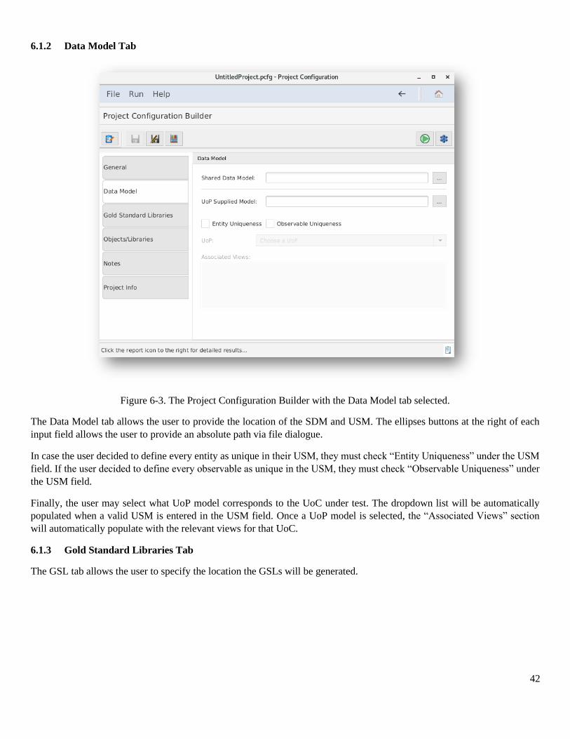
42
6.1.2 Data Model Tab
Figure 6-3. The Project Configuration Builder with the Data Model tab selected.
The Data Model tab allows the user to provide the location of the SDM and USM. The ellipses buttons at the right of each
input field allows the user to provide an absolute path via file dialogue.
In case the user decided to define every entity as unique in their USM, they must check “Entity Uniqueness” under the USM
field. If the user decided to define every observable as unique in the USM, they must check “Observable Uniqueness” under
the USM field.
Finally, the user may select what UoP model corresponds to the UoC under test. The dropdown list will be automatically
populated when a valid USM is entered in the USM field. Once a UoP model is selected, the “Associated Views” section
will automatically populate with the relevant views for that UoC.
6.1.3 Gold Standard Libraries Tab
The GSL tab allows the user to specify the location the GSLs will be generated.
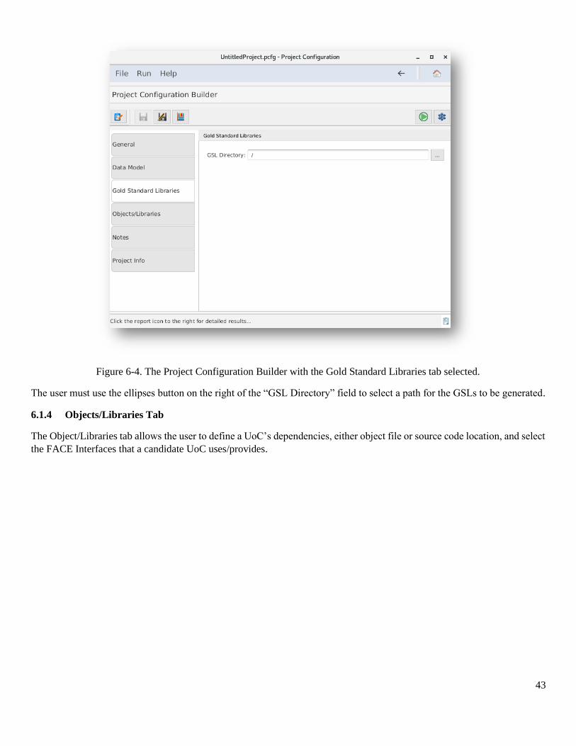
43
Figure 6-4. The Project Configuration Builder with the Gold Standard Libraries tab selected.
The user must use the ellipses button on the right of the “GSL Directory” field to select a path for the GSLs to be generated.
6.1.4 Objects/Libraries Tab
The Object/Libraries tab allows the user to define a UoC’s dependencies, either object file or source code location, and select
the FACE Interfaces that a candidate UoC uses/provides.
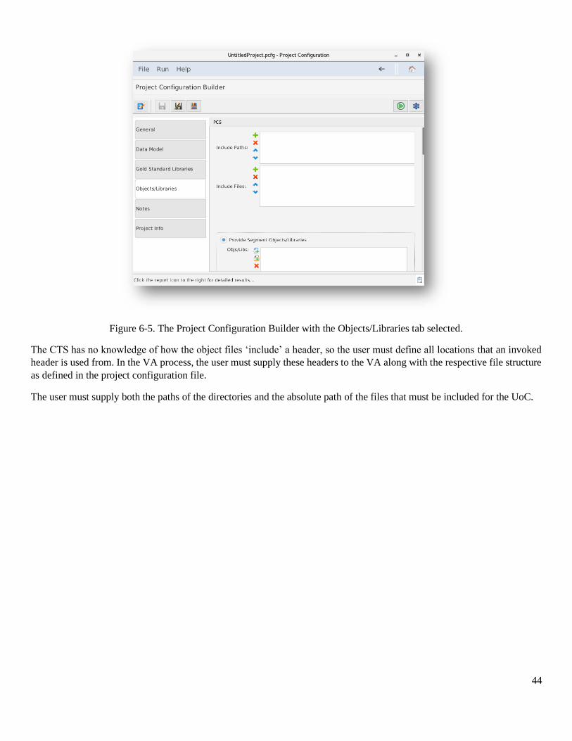
44
Figure 6-5. The Project Configuration Builder with the Objects/Libraries tab selected.
The CTS has no knowledge of how the object files ‘include’ a header, so the user must define all locations that an invoked
header is used from. In the VA process, the user must supply these headers to the VA along with the respective file structure
as defined in the project configuration file.
The user must supply both the paths of the directories and the absolute path of the files that must be included for the UoC.
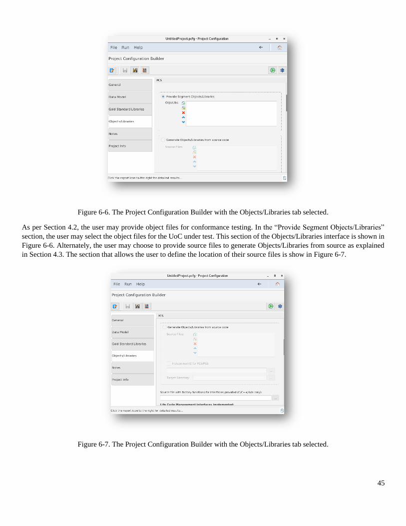
45
Figure 6-6. The Project Configuration Builder with the Objects/Libraries tab selected.
As per Section 4.2, the user may provide object files for conformance testing. In the “Provide Segment Objects/Libraries”
section, the user may select the object files for the UoC under test. This section of the Objects/Libraries interface is shown in
Figure 6-6. Alternately, the user may choose to provide source files to generate Objects/Libraries from source as explained
in Section 4.3. The section that allows the user to define the location of their source files is show in Figure 6-7.
Figure 6-7. The Project Configuration Builder with the Objects/Libraries tab selected.
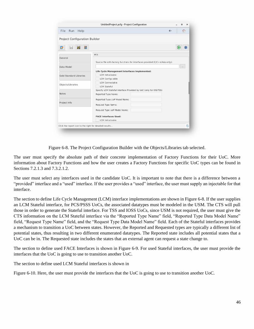
46
Figure 6-8. The Project Configuration Builder with the Objects/Libraries tab selected.
The user must specify the absolute path of their concrete implementation of Factory Functions for their UoC. More
information about Factory Functions and how the user creates a Factory Functions for specific UoC types can be found in
Sections 7.2.1.3 and 7.3.2.1.2.
The user must select any interfaces used in the candidate UoC. It is important to note that there is a difference between a
“provided” interface and a “used” interface. If the user provides a “used” interface, the user must supply an injectable for that
interface.
The section to define Life Cycle Management (LCM) interface implementations are shown in Figure 6-8. If the user supplies
an LCM Stateful interface, for PCS/PSSS UoCs, the associated datatypes must be modeled in the USM. The CTS will pull
those in order to generate the Stateful interface. For TSS and IOSS UoCs, since USM is not required, the user must give the
CTS information on the LCM Stateful interface via the “Reported Type Name” field, “Reported Type Data Model Name”
field, “Request Type Name” field, and the “Request Type Data Model Name” field. Each of the Stateful interfaces provides
a mechanism to transition a UoC between states. However, the Reported and Requested types are typically a different list of
potential states, thus resulting in two different enumerated datatypes. The Reported state includes all potential states that a
UoC can be in. The Requested state includes the states that an external agent can request a state change to.
The section to define used FACE Interfaces is shown in Figure 6-9. For used Stateful interfaces, the user must provide the
interfaces that the UoC is going to use to transition another UoC.
The section to define used LCM Stateful interfaces is shown in
Figure 6-10. Here, the user must provide the interfaces that the UoC is going to use to transition another UoC.
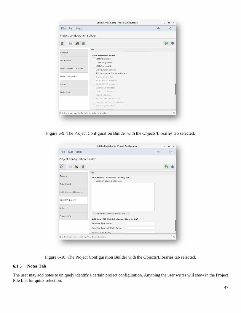
47
Figure 6-9. The Project Configuration Builder with the Objects/Libraries tab selected.
Figure 6-10. The Project Configuration Builder with the Objects/Libraries tab selected.
6.1.5 Notes Tab
The user may add notes to uniquely identify a certain project configuration. Anything the user writes will show in the Project
File List for quick selection.
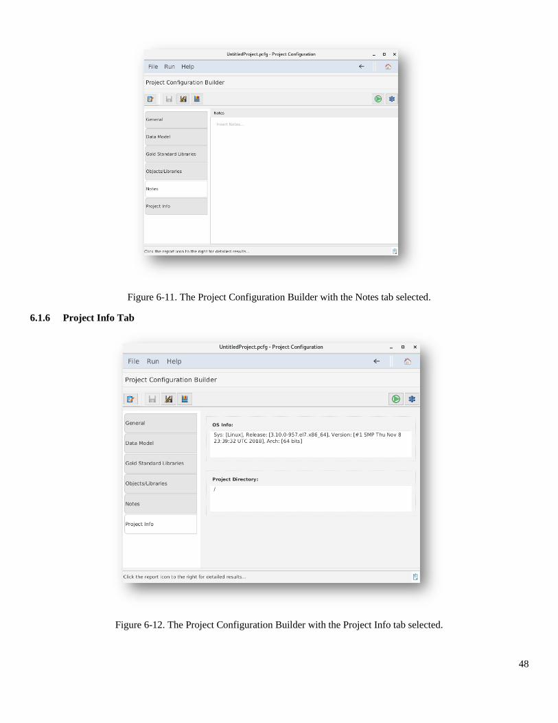
48
Figure 6-11. The Project Configuration Builder with the Notes tab selected.
6.1.6 Project Info Tab
Figure 6-12. The Project Configuration Builder with the Project Info tab selected.
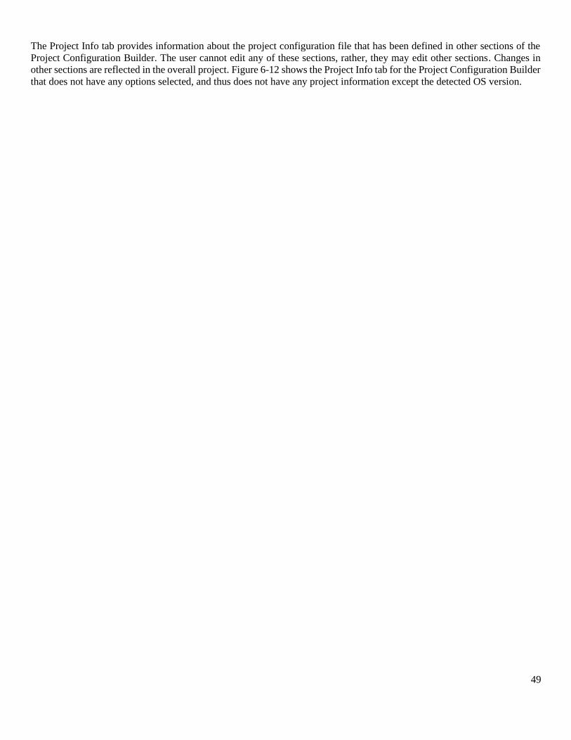
49
The Project Info tab provides information about the project configuration file that has been defined in other sections of the
Project Configuration Builder. The user cannot edit any of these sections, rather, they may edit other sections. Changes in
other sections are reflected in the overall project. Figure 6-12 shows the Project Info tab for the Project Configuration Builder
that does not have any options selected, and thus does not have any project information except the detected OS version.
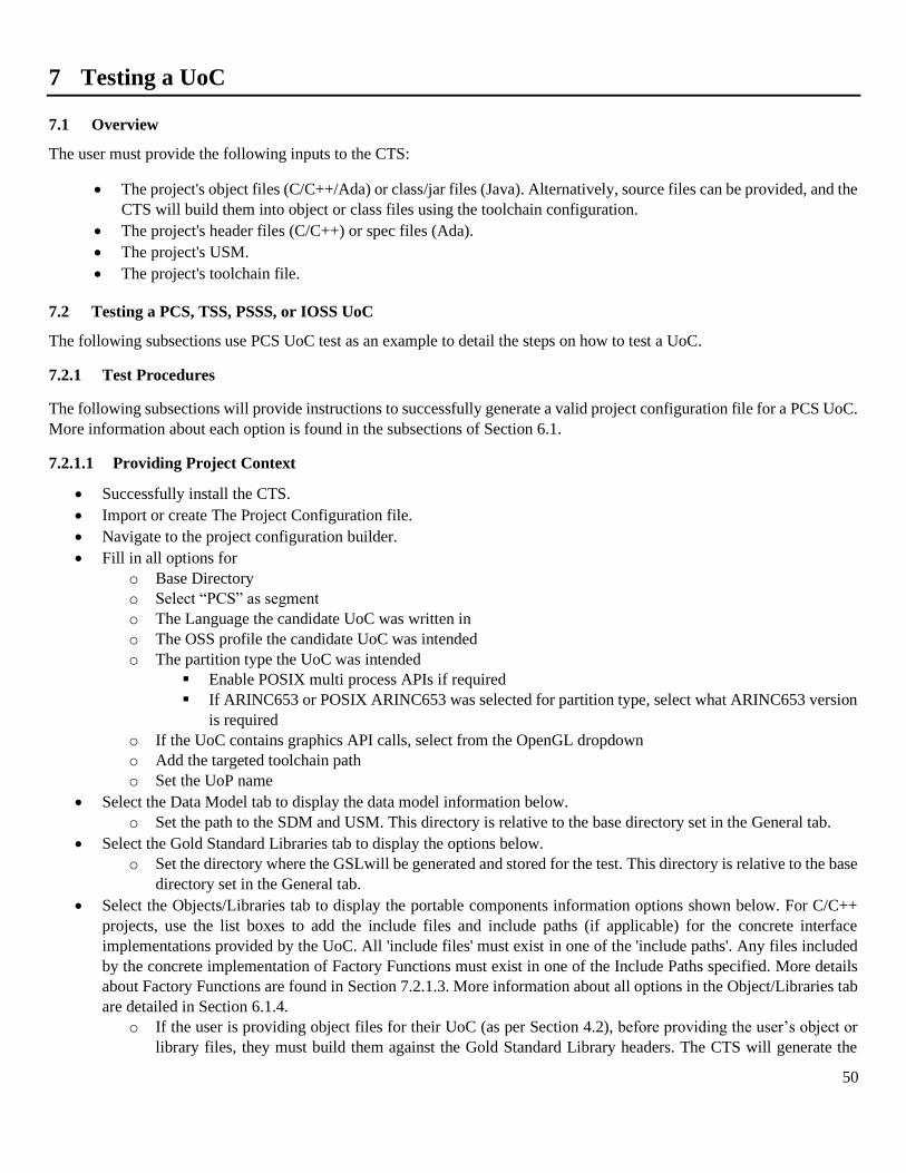
50
7 Testing a UoC
7.1 Overview
The user must provide the following inputs to the CTS:
• The project's object files (C/C++/Ada) or class/jar files (Java). Alternatively, source files can be provided, and the
CTS will build them into object or class files using the toolchain configuration.
• The project's header files (C/C++) or spec files (Ada).
• The project's USM.
• The project's toolchain file.
7.2 Testing a PCS, TSS, PSSS, or IOSS UoC
The following subsections use PCS UoC test as an example to detail the steps on how to test a UoC.
7.2.1 Test Procedures
The following subsections will provide instructions to successfully generate a valid project configuration file for a PCS UoC.
More information about each option is found in the subsections of Section 6.1.
7.2.1.1 Providing Project Context
• Successfully install the CTS.
• Import or create The Project Configuration file.
• Navigate to the project configuration builder.
• Fill in all options for
o Base Directory
o Select “PCS” as segment
o The Language the candidate UoC was written in
o The OSS profile the candidate UoC was intended
o The partition type the UoC was intended
▪ Enable POSIX multi process APIs if required
▪ If ARINC653 or POSIX ARINC653 was selected for partition type, select what ARINC653 version
is required
o If the UoC contains graphics API calls, select from the OpenGL dropdown
o Add the targeted toolchain path
o Set the UoP name
• Select the Data Model tab to display the data model information below.
o Set the path to the SDM and USM. This directory is relative to the base directory set in the General tab.
• Select the Gold Standard Libraries tab to display the options below.
o Set the directory where the GSLwill be generated and stored for the test. This directory is relative to the base
directory set in the General tab.
• Select the Objects/Libraries tab to display the portable components information options shown below. For C/C++
projects, use the list boxes to add the include files and include paths (if applicable) for the concrete interface
implementations provided by the UoC. All 'include files' must exist in one of the 'include paths'. Any files included
by the concrete implementation of Factory Functions must exist in one of the Include Paths specified. More details
about Factory Functions are found in Section 7.2.1.3. More information about all options in the Object/Libraries tab
are detailed in Section 6.1.4.
o If the user is providing object files for their UoC (as per Section 4.2), before providing the user’s object or
library files, they must build them against the Gold Standard Library headers. The CTS will generate the
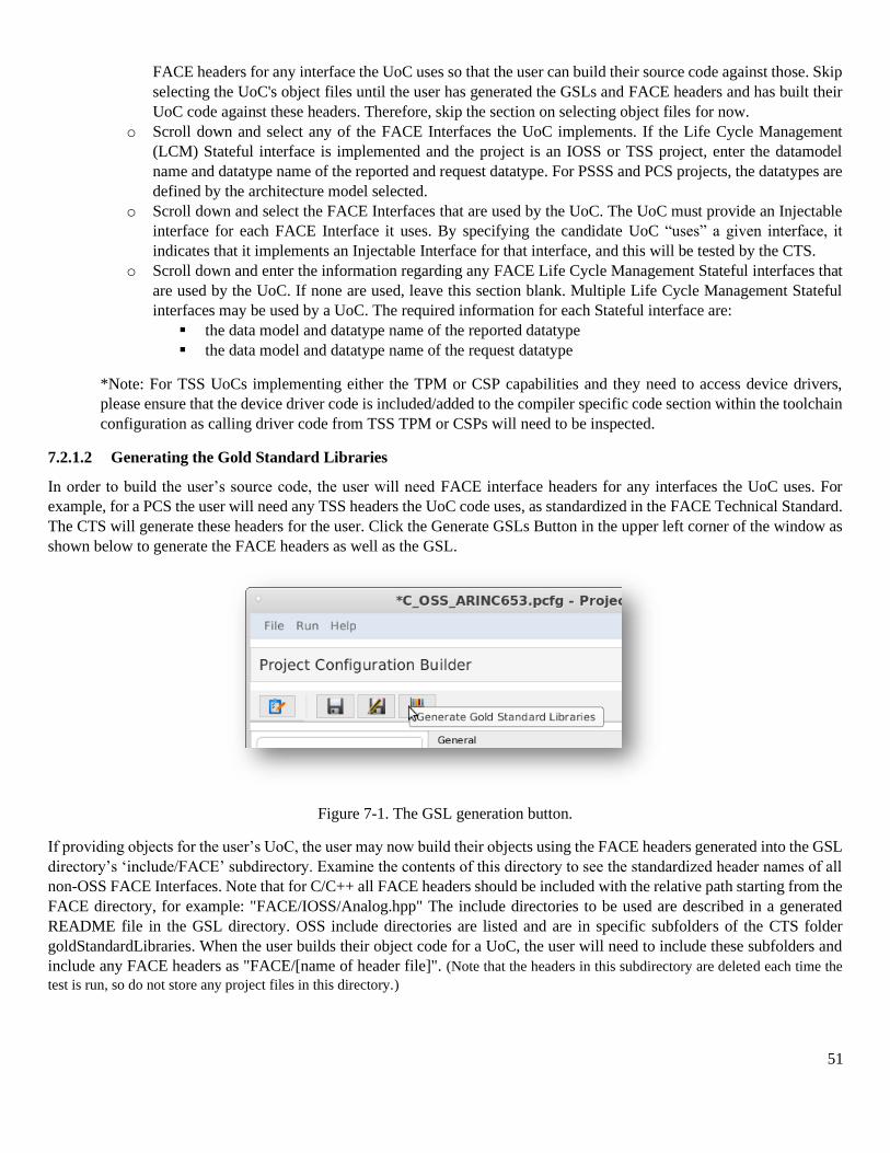
51
FACE headers for any interface the UoC uses so that the user can build their source code against those. Skip
selecting the UoC's object files until the user has generated the GSLs and FACE headers and has built their
UoC code against these headers. Therefore, skip the section on selecting object files for now.
o Scroll down and select any of the FACE Interfaces the UoC implements. If the Life Cycle Management
(LCM) Stateful interface is implemented and the project is an IOSS or TSS project, enter the datamodel
name and datatype name of the reported and request datatype. For PSSS and PCS projects, the datatypes are
defined by the architecture model selected.
o Scroll down and select the FACE Interfaces that are used by the UoC. The UoC must provide an Injectable
interface for each FACE Interface it uses. By specifying the candidate UoC “uses” a given interface, it
indicates that it implements an Injectable Interface for that interface, and this will be tested by the CTS.
o Scroll down and enter the information regarding any FACE Life Cycle Management Stateful interfaces that
are used by the UoC. If none are used, leave this section blank. Multiple Life Cycle Management Stateful
interfaces may be used by a UoC. The required information for each Stateful interface are:
▪ the data model and datatype name of the reported datatype
▪ the data model and datatype name of the request datatype
*Note: For TSS UoCs implementing either the TPM or CSP capabilities and they need to access device drivers,
please ensure that the device driver code is included/added to the compiler specific code section within the toolchain
configuration as calling driver code from TSS TPM or CSPs will need to be inspected.
7.2.1.2 Generating the Gold Standard Libraries
In order to build the user’s source code, the user will need FACE interface headers for any interfaces the UoC uses. For
example, for a PCS the user will need any TSS headers the UoC code uses, as standardized in the FACE Technical Standard.
The CTS will generate these headers for the user. Click the Generate GSLs Button in the upper left corner of the window as
shown below to generate the FACE headers as well as the GSL.
Figure 7-1. The GSL generation button.
If providing objects for the user’s UoC, the user may now build their objects using the FACE headers generated into the GSL
directory’s ‘include/FACE’ subdirectory. Examine the contents of this directory to see the standardized header names of all
non-OSS FACE Interfaces. Note that for C/C++ all FACE headers should be included with the relative path starting from the
FACE directory, for example: "FACE/IOSS/Analog.hpp" The include directories to be used are described in a generated
README file in the GSL directory. OSS include directories are listed and are in specific subfolders of the CTS folder
goldStandardLibraries. When the user builds their object code for a UoC, the user will need to include these subfolders and
include any FACE headers as "FACE/[name of header file]". (Note that the headers in this subdirectory are deleted each time the
test is run, so do not store any project files in this directory.)
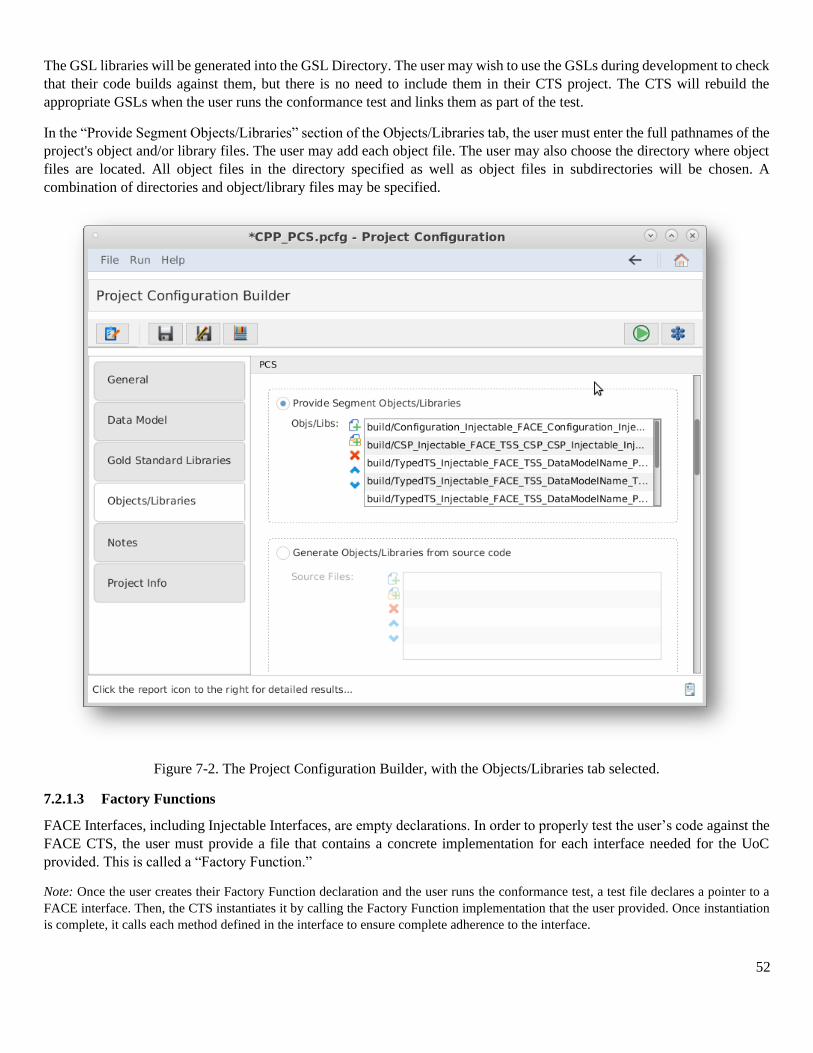
52
The GSL libraries will be generated into the GSL Directory. The user may wish to use the GSLs during development to check
that their code builds against them, but there is no need to include them in their CTS project. The CTS will rebuild the
appropriate GSLs when the user runs the conformance test and links them as part of the test.
In the “Provide Segment Objects/Libraries” section of the Objects/Libraries tab, the user must enter the full pathnames of the
project's object and/or library files. The user may add each object file. The user may also choose the directory where object
files are located. All object files in the directory specified as well as object files in subdirectories will be chosen. A
combination of directories and object/library files may be specified.
Figure 7-2. The Project Configuration Builder, with the Objects/Libraries tab selected.
7.2.1.3 Factory Functions
FACE Interfaces, including Injectable Interfaces, are empty declarations. In order to properly test the user’s code against the
FACE CTS, the user must provide a file that contains a concrete implementation for each interface needed for the UoC
provided. This is called a “Factory Function.”
Note: Once the user creates their Factory Function declaration and the user runs the conformance test, a test file declares a pointer to a
FACE interface. Then, the CTS instantiates it by calling the Factory Function implementation that the user provided. Once instantiation
is complete, it calls each method defined in the interface to ensure complete adherence to the interface.
53
7.2.1.3.1 Generation
To determine which factory functions are necessary, the user must generate the GSL for their project. After generation, the
user must find a generated header/spec file named, “CTS_Factory_Functions” in the generated subfolder 'build/GSL/include',
which will contain required interfaces.
7.2.1.3.2 Providing a Factory Function Implementation
The user must take note of the “CTS_Factory_Functions” file that was generated by the GSLs. The user must provide a file
that implements each of these functions. The following paragraphs detail what the user must do per each language the user’s
UoC implements.
For C/C++, this file (CTS_Factory_Functions .h or .hpp) will contain the declarations of all expected factory functions that
the CTS requires for testing the user’s UoC. The implementation for each function must instantiate the corresponding concrete
class and return a pointer to that object (the return type will be a pointer to the FACE ‘abstract’ class). Returning a null pointer
is not acceptable. This source file must be provided with the user’s project and will be reviewed to ensure it instantiates the
user’s UoC's concrete class for that interface.
For Ada, this will generate a spec file (.ads) cts_factory_functions.ads which has the procedures the user must implement in
the source file. The source file for Ada must be named "cts_factory_functions.adb" and implement each of these procedures,
returning a concrete version of each type as an access type. In the text field labeled "Source file with factory functions for
interfaces provided (C/C++/Ada only)", use the '...' button to the right to browse for the source file. Any header files included
by the source file must exist in one of the Include Paths specified above.
For Java, a source file named CTS_Factory_Functions.java will be generated in the factory/ subfolder (package subfolder).
The user must fill in the implementation of each function, add any imports, and add this to the user’s project in the CTS in
this file field. Note that this file will NOT be overwritten so if the interfaces the UoC uses have changed, the user must delete
their file in order to regenerate a new one with the new set of functions to implement.
7.2.1.4 Validating and Testing a Project
1. Select to verify that the Project Configuration File is valid.
2. Click the button at the top of the screen to test the segment. (This may take a few minutes). The
results will be written to a PDF file. The directory of the results file will be in the directory of the project configuration
file. This directory path will be listed in the "Output File Location" of the Conformance Test Results page.
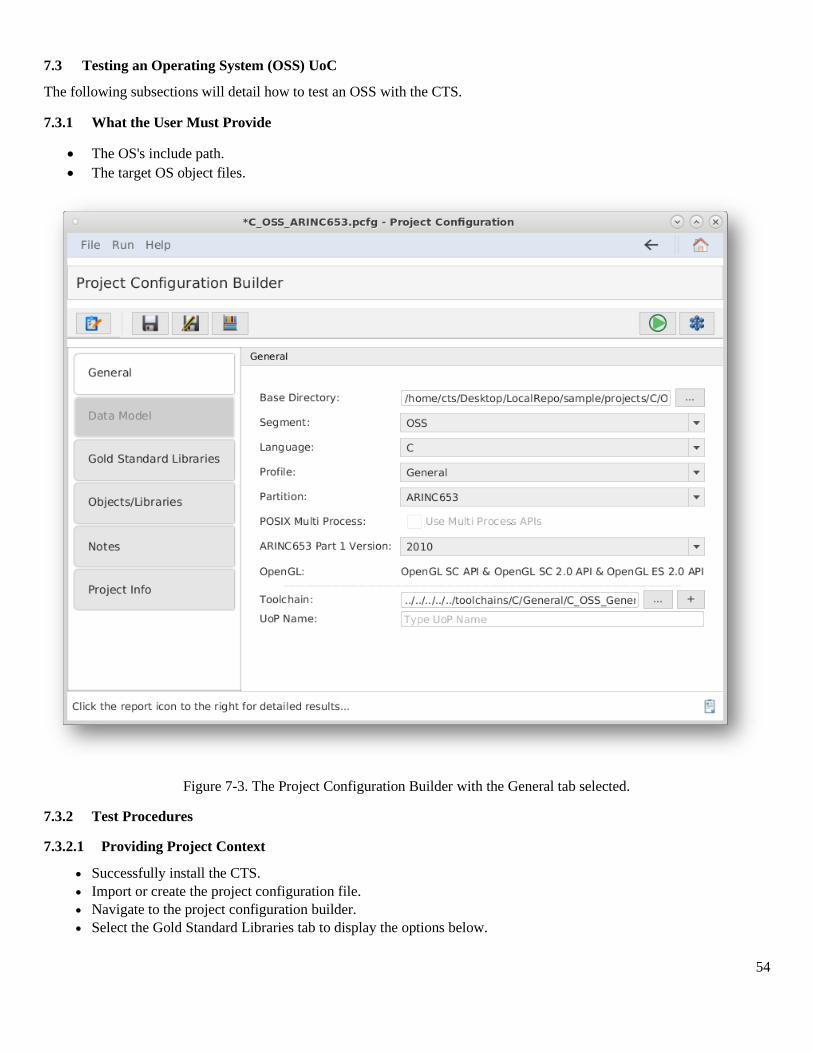
54
7.3 Testing an Operating System (OSS) UoC
The following subsections will detail how to test an OSS with the CTS.
7.3.1 What the User Must Provide
• The OS's include path.
• The target OS object files.
Figure 7-3. The Project Configuration Builder with the General tab selected.
7.3.2 Test Procedures
7.3.2.1 Providing Project Context
• Successfully install the CTS.
• Import or create the project configuration file.
• Navigate to the project configuration builder.
• Select the Gold Standard Libraries tab to display the options below.
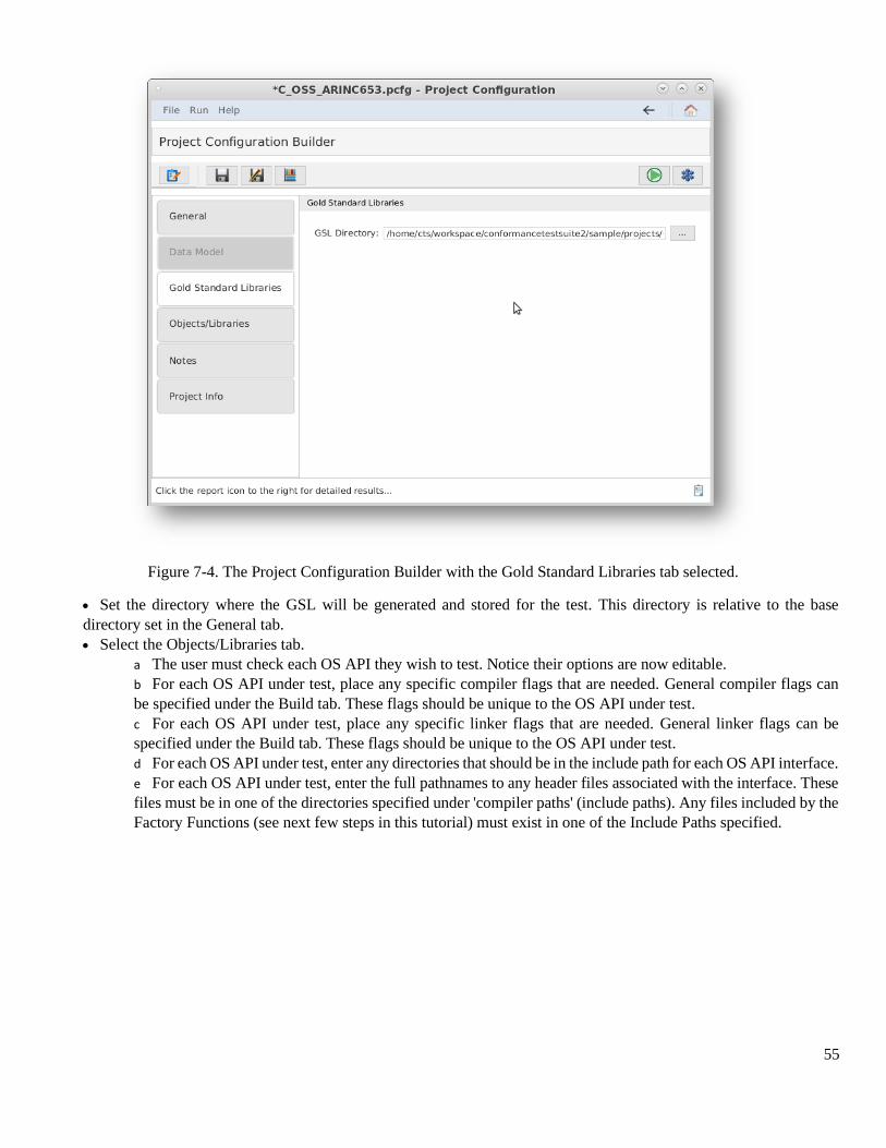
55
Figure 7-4. The Project Configuration Builder with the Gold Standard Libraries tab selected.
• Set the directory where the GSL will be generated and stored for the test. This directory is relative to the base
directory set in the General tab.
• Select the Objects/Libraries tab.
a The user must check each OS API they wish to test. Notice their options are now editable.
b For each OS API under test, place any specific compiler flags that are needed. General compiler flags can
be specified under the Build tab. These flags should be unique to the OS API under test.
c For each OS API under test, place any specific linker flags that are needed. General linker flags can be
specified under the Build tab. These flags should be unique to the OS API under test.
d For each OS API under test, enter any directories that should be in the include path for each OS API interface.
e For each OS API under test, enter the full pathnames to any header files associated with the interface. These
files must be in one of the directories specified under 'compiler paths' (include paths). Any files included by the
Factory Functions (see next few steps in this tutorial) must exist in one of the Include Paths specified.
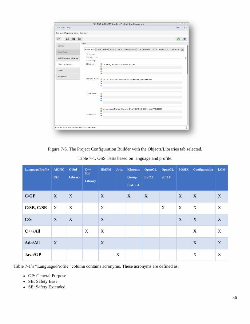
56
Figure 7-5. The Project Configuration Builder with the Objects/Libraries tab selected.
Table 7-1. OSS Tests based on language and profile.
Language/Profile ARINC
653
C Std
Library
C++
Std
Library
HMFM Java Khronus
Group
EGL 1.4
OpenGL
ES 2.0
OpenGL
SC 2.0
POSIX Configuration LCM
C/GP X X X X X X X X
C/SB, C/SE X X X X X X X
C/S X X X X X X
C++/All X X X X
Ada/All X X X X
Java/GP X X X
Table 7-1’s “Language/Profile” column contains acronyms. These acronyms are defined as:
• GP: General Purpose
• SB: Safety Base
• SE: Safety Extended
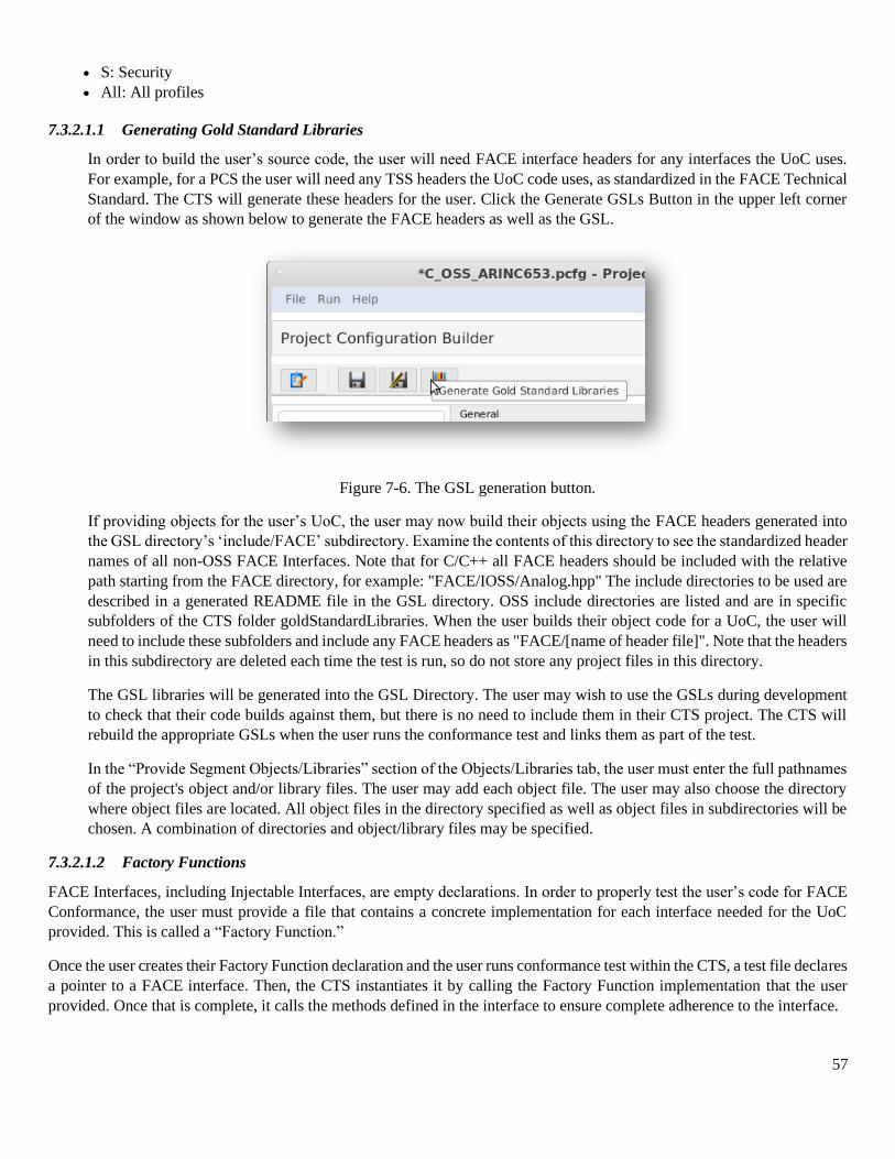
57
• S: Security
• All: All profiles
7.3.2.1.1 Generating Gold Standard Libraries
In order to build the user’s source code, the user will need FACE interface headers for any interfaces the UoC uses.
For example, for a PCS the user will need any TSS headers the UoC code uses, as standardized in the FACE Technical
Standard. The CTS will generate these headers for the user. Click the Generate GSLs Button in the upper left corner
of the window as shown below to generate the FACE headers as well as the GSL.
Figure 7-6. The GSL generation button.
If providing objects for the user’s UoC, the user may now build their objects using the FACE headers generated into
the GSL directory’s ‘include/FACE’ subdirectory. Examine the contents of this directory to see the standardized header
names of all non-OSS FACE Interfaces. Note that for C/C++ all FACE headers should be included with the relative
path starting from the FACE directory, for example: "FACE/IOSS/Analog.hpp" The include directories to be used are
described in a generated README file in the GSL directory. OSS include directories are listed and are in specific
subfolders of the CTS folder goldStandardLibraries. When the user builds their object code for a UoC, the user will
need to include these subfolders and include any FACE headers as "FACE/[name of header file]". Note that the headers
in this subdirectory are deleted each time the test is run, so do not store any project files in this directory.
The GSL libraries will be generated into the GSL Directory. The user may wish to use the GSLs during development
to check that their code builds against them, but there is no need to include them in their CTS project. The CTS will
rebuild the appropriate GSLs when the user runs the conformance test and links them as part of the test.
In the “Provide Segment Objects/Libraries” section of the Objects/Libraries tab, the user must enter the full pathnames
of the project's object and/or library files. The user may add each object file. The user may also choose the directory
where object files are located. All object files in the directory specified as well as object files in subdirectories will be
chosen. A combination of directories and object/library files may be specified.
7.3.2.1.2 Factory Functions
FACE Interfaces, including Injectable Interfaces, are empty declarations. In order to properly test the user’s code for FACE
Conformance, the user must provide a file that contains a concrete implementation for each interface needed for the UoC
provided. This is called a “Factory Function.”
Once the user creates their Factory Function declaration and the user runs conformance test within the CTS, a test file declares
a pointer to a FACE interface. Then, the CTS instantiates it by calling the Factory Function implementation that the user
provided. Once that is complete, it calls the methods defined in the interface to ensure complete adherence to the interface.
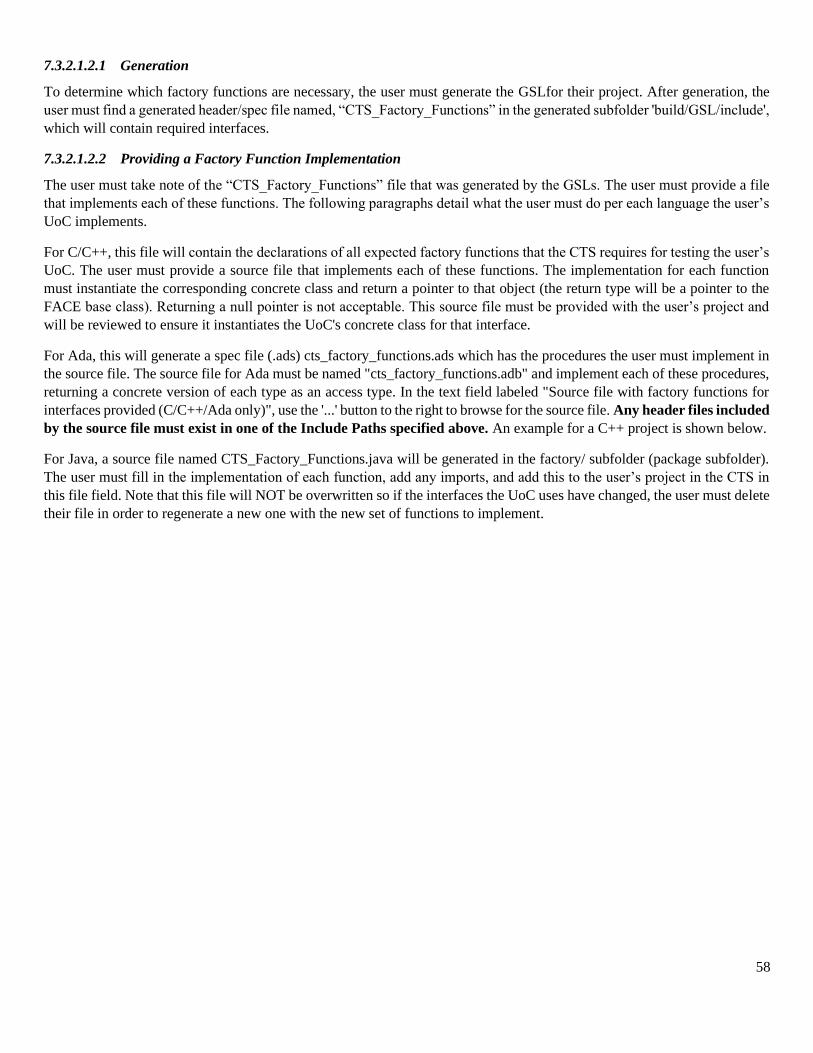
58
7.3.2.1.2.1 Generation
To determine which factory functions are necessary, the user must generate the GSLfor their project. After generation, the
user must find a generated header/spec file named, “CTS_Factory_Functions” in the generated subfolder 'build/GSL/include',
which will contain required interfaces.
7.3.2.1.2.2 Providing a Factory Function Implementation
The user must take note of the “CTS_Factory_Functions” file that was generated by the GSLs. The user must provide a file
that implements each of these functions. The following paragraphs detail what the user must do per each language the user’s
UoC implements.
For C/C++, this file will contain the declarations of all expected factory functions that the CTS requires for testing the user’s
UoC. The user must provide a source file that implements each of these functions. The implementation for each function
must instantiate the corresponding concrete class and return a pointer to that object (the return type will be a pointer to the
FACE base class). Returning a null pointer is not acceptable. This source file must be provided with the user’s project and
will be reviewed to ensure it instantiates the UoC's concrete class for that interface.
For Ada, this will generate a spec file (.ads) cts_factory_functions.ads which has the procedures the user must implement in
the source file. The source file for Ada must be named "cts_factory_functions.adb" and implement each of these procedures,
returning a concrete version of each type as an access type. In the text field labeled "Source file with factory functions for
interfaces provided (C/C++/Ada only)", use the '...' button to the right to browse for the source file. Any header files included
by the source file must exist in one of the Include Paths specified above. An example for a C++ project is shown below.
For Java, a source file named CTS_Factory_Functions.java will be generated in the factory/ subfolder (package subfolder).
The user must fill in the implementation of each function, add any imports, and add this to the user’s project in the CTS in
this file field. Note that this file will NOT be overwritten so if the interfaces the UoC uses have changed, the user must delete
their file in order to regenerate a new one with the new set of functions to implement.
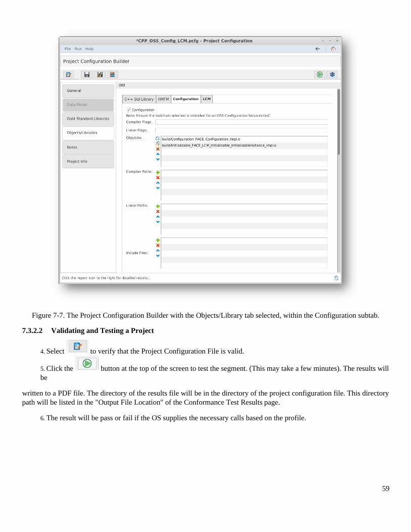
59
Figure 7-7. The Project Configuration Builder with the Objects/Library tab selected, within the Configuration subtab.
7.3.2.2 Validating and Testing a Project
4. Select to verify that the Project Configuration File is valid.
5. Click the button at the top of the screen to test the segment. (This may take a few minutes). The results will
be
written to a PDF file. The directory of the results file will be in the directory of the project configuration file. This directory
path will be listed in the "Output File Location" of the Conformance Test Results page.
6. The result will be pass or fail if the OS supplies the necessary calls based on the profile.
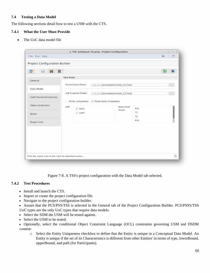
60
7.4 Testing a Data Model
The following sections detail how to test a USM with the CTS.
7.4.1 What the User Must Provide
• The UoC data model file
Figure 7-8. A TSS's project configuration with the Data Model tab selected.
7.4.2 Test Procedures
• Install and launch the CTS.
• Import or create the project configuration file.
• Navigate to the project configuration builder.
• Assure that the PCS/PSS/TSS is selected in the General tab of the Project Configuration Builder. PCS/PSSS/TSS
UoC types are the only UoC types that require data models.
• Select the SDM the USM will be tested against.
• Select the USM to be tested.
• Optionally, select the conditional Object Constraint Language (OCL) constraints governing USM and DSDM
content:
o Select the Entity Uniqueness checkbox to define that the Entity is unique in a Conceptual Data Model. An
Entity is unique if the set of its Characteristics is different from other Entities' in terms of type, lowerBound,
upperBound, and path (for Participants).
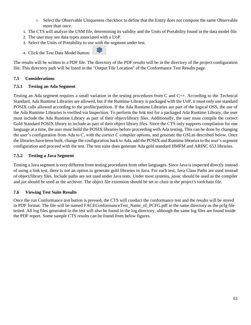
61
o Select the Observable Uniqueness checkbox to define that the Entity does not compose the same Observable
more than once.
1. The CTS will analyze the USM file, determining its validity and the Units of Portability found in the data model file.
2. The user may see data types associated with a UoP.
3. Select the Units of Portability to use with the segment under test.
4. Click the Test Data Model button:
The results will be written to a PDF file. The directory of the PDF results will be in the directory of the project configuration
file. This directory path will be listed in the "Output File Location" of the Conformance Test Results page.
7.5 Considerations
7.5.1 Testing an Ada Segment
Testing an Ada segment requires a small variation in the testing procedures from C and C++. According to the Technical
Standard, Ada Runtime Libraries are allowed, but if the Runtime Library is packaged with the UoP, it must only use standard
POSIX calls allowed according to the profile/partition. If the Ada Runtime Libraries are part of the logical OSS, the use of
the Ada Runtime Libraries is verified via Inspection. To perform the link test for a packaged Ada Runtime Library, the user
must include the Ada Runtime Library as part of their object/library files. Additionally, the user must compile the correct
Gold Standard POSIX library to include as part of their object library files. Since the CTS only supports compilation for one
language at a time, the user must build the POSIX libraries before proceeding with Ada testing. This can be done by changing
the user’s configuration from Ada to C, with the correct C compiler options, and generate the GSLas described below. Once
the libraries have been built, change the configuration back to Ada, add the POSIX and Runtime libraries to the user’s segment
configuration and proceed with the test. The test suite does generate Ada gold standard HMFM and ARINC 653 libraries.
7.5.2 Testing a Java Segment
Testing a Java segment is very different from testing procedures from other languages. Since Java is inspected directly instead
of using a link test, there is not an option to generate gold libraries in Java. For each test, Java Class Paths are used instead
of object/library files. Include paths are not used under Java tests. Under most systems, javac should be used as the compiler
and jar should be used as the archiver. The object file extension should be set to class in the project's toolchain file.
7.6 Viewing Test Suite Results
Once the run Conformance test button is pressed, the CTS will conduct the conformance test and the results will be stored
in PDF format. The file will be named FACEConformanceTest_Name_of_PCFG.pdf in the same directory as the pcfg file
tested. All log files generated in the test will also be found in the log directory, although the same log files are found inside
the PDF report. Some sample CTS results can be found from below figures.
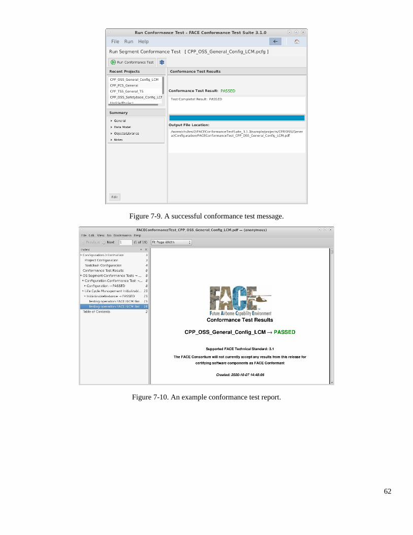
62
Figure 7-9. A successful conformance test message.
Figure 7-10. An example conformance test report.
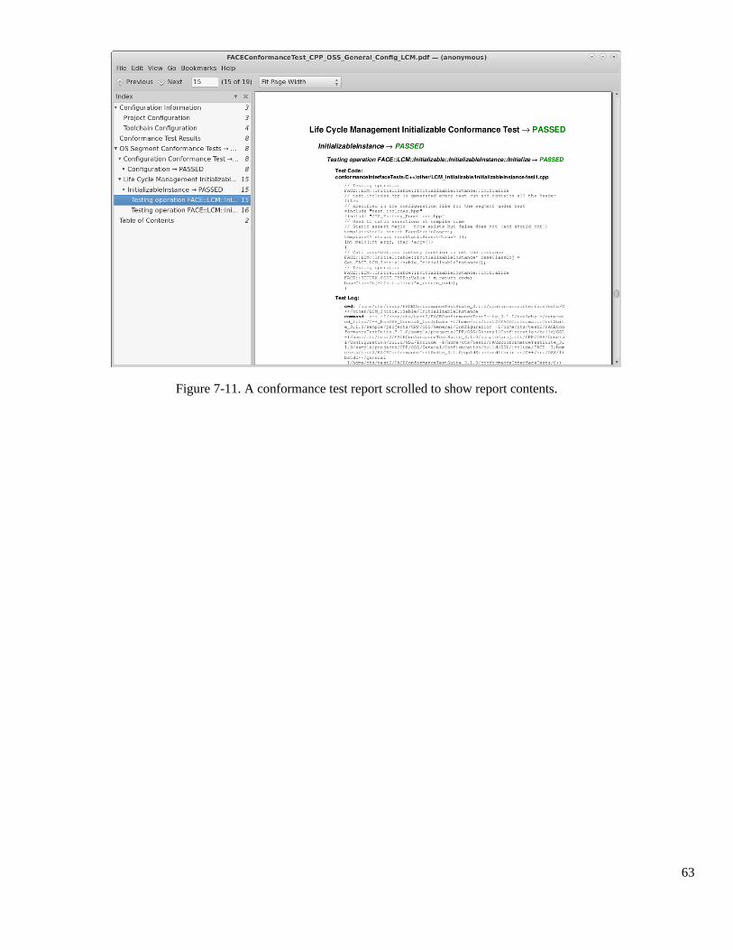
63
Figure 7-11. A conformance test report scrolled to show report contents.
64
8 References
[1] The Open Group, "FACE TECHNICAL STANDARD, EDITION 3.1," 2020. [Online]. Available:
https://publications.opengroup.org/.
[2] The Object Management Group, "Interface Definition Language," March 2018. [Online]. Available:
https://www.omg.org/spec/IDL/About-IDL/.
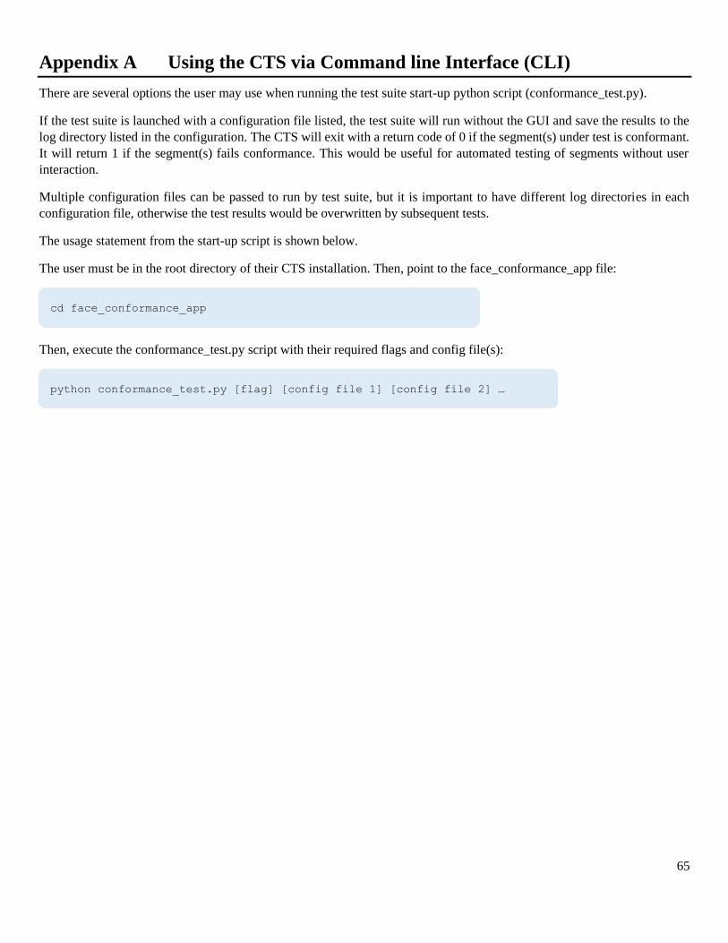
65
Appendix A Using the CTS via Command line Interface (CLI)
There are several options the user may use when running the test suite start-up python script (conformance_test.py).
If the test suite is launched with a configuration file listed, the test suite will run without the GUI and save the results to the
log directory listed in the configuration. The CTS will exit with a return code of 0 if the segment(s) under test is conformant.
It will return 1 if the segment(s) fails conformance. This would be useful for automated testing of segments without user
interaction.
Multiple configuration files can be passed to run by test suite, but it is important to have different log directories in each
configuration file, otherwise the test results would be overwritten by subsequent tests.
The usage statement from the start-up script is shown below.
The user must be in the root directory of their CTS installation. Then, point to the face_conformance_app file:
Then, execute the conformance_test.py script with their required flags and config file(s):
cd face_conformance_app
python conformance_test.py [flag] [config file 1] [config file 2] …
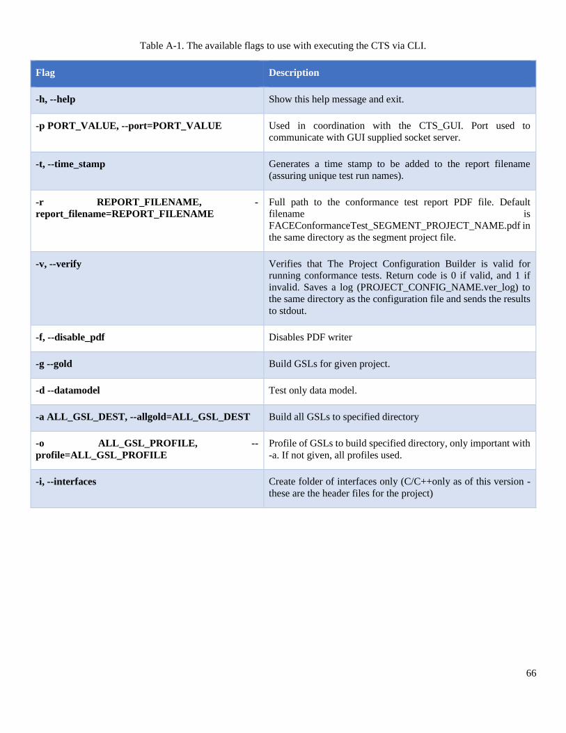
66
Table A-1. The available flags to use with executing the CTS via CLI.
Flag Description
-h, --help Show this help message and exit.
-p PORT_VALUE, --port=PORT_VALUE Used in coordination with the CTS_GUI. Port used to
communicate with GUI supplied socket server.
-t, --time_stamp Generates a time stamp to be added to the report filename
(assuring unique test run names).
-r REPORT_FILENAME, -
report_filename=REPORT_FILENAME
Full path to the conformance test report PDF file. Default
filename is
FACEConformanceTest_SEGMENT_PROJECT_NAME.pdf in
the same directory as the segment project file.
-v, --verify Verifies that The Project Configuration Builder is valid for
running conformance tests. Return code is 0 if valid, and 1 if
invalid. Saves a log (PROJECT_CONFIG_NAME.ver_log) to
the same directory as the configuration file and sends the results
to stdout.
-f, --disable_pdf Disables PDF writer
-g --gold Build GSLs for given project.
-d --datamodel Test only data model.
-a ALL_GSL_DEST, --allgold=ALL_GSL_DEST Build all GSLs to specified directory
-o ALL_GSL_PROFILE, --
profile=ALL_GSL_PROFILE
Profile of GSLs to build specified directory, only important with
-a. If not given, all profiles used.
-i, --interfaces Create folder of interfaces only (C/C++only as of this version -
these are the header files for the project)
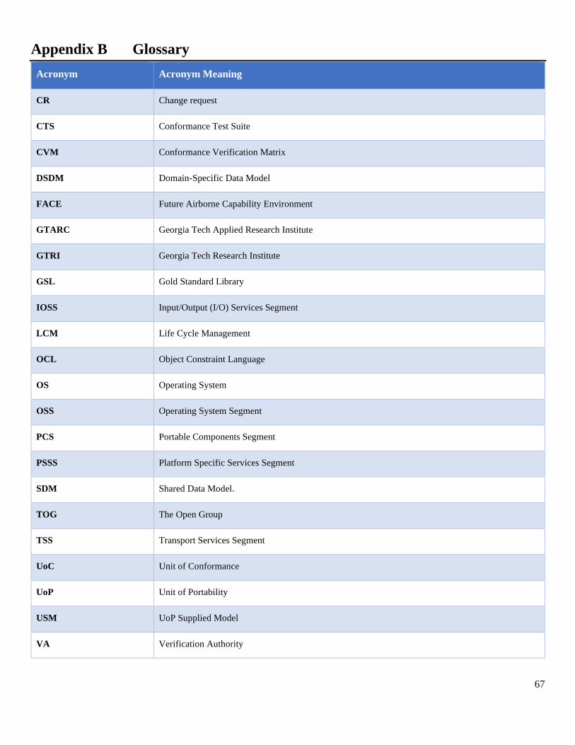
67
Appendix B Glossary
Acronym Acronym Meaning
CR Change request
CTS Conformance Test Suite
CVM Conformance Verification Matrix
DSDM Domain-Specific Data Model
FACE Future Airborne Capability Environment
GTARC Georgia Tech Applied Research Institute
GTRI Georgia Tech Research Institute
GSL Gold Standard Library
IOSS Input/Output (I/O) Services Segment
LCM Life Cycle Management
OCL Object Constraint Language
OS Operating System
OSS Operating System Segment
PCS Portable Components Segment
PSSS Platform Specific Services Segment
SDM Shared Data Model.
TOG The Open Group
TSS Transport Services Segment
UoC Unit of Conformance
UoP Unit of Portability
USM UoP Supplied Model
VA Verification Authority
68
Appendix C Constraints
POSIX and ARINC interface testing is performed on functions only. Data types and constants are not tested comprehensively.
A POSIX or ARINC conformance test should be used to fully test those aspects.
69
Appendix D Issues
Any issue found concerning the CTS should be reported to https://ticketing.facesoftware.org.
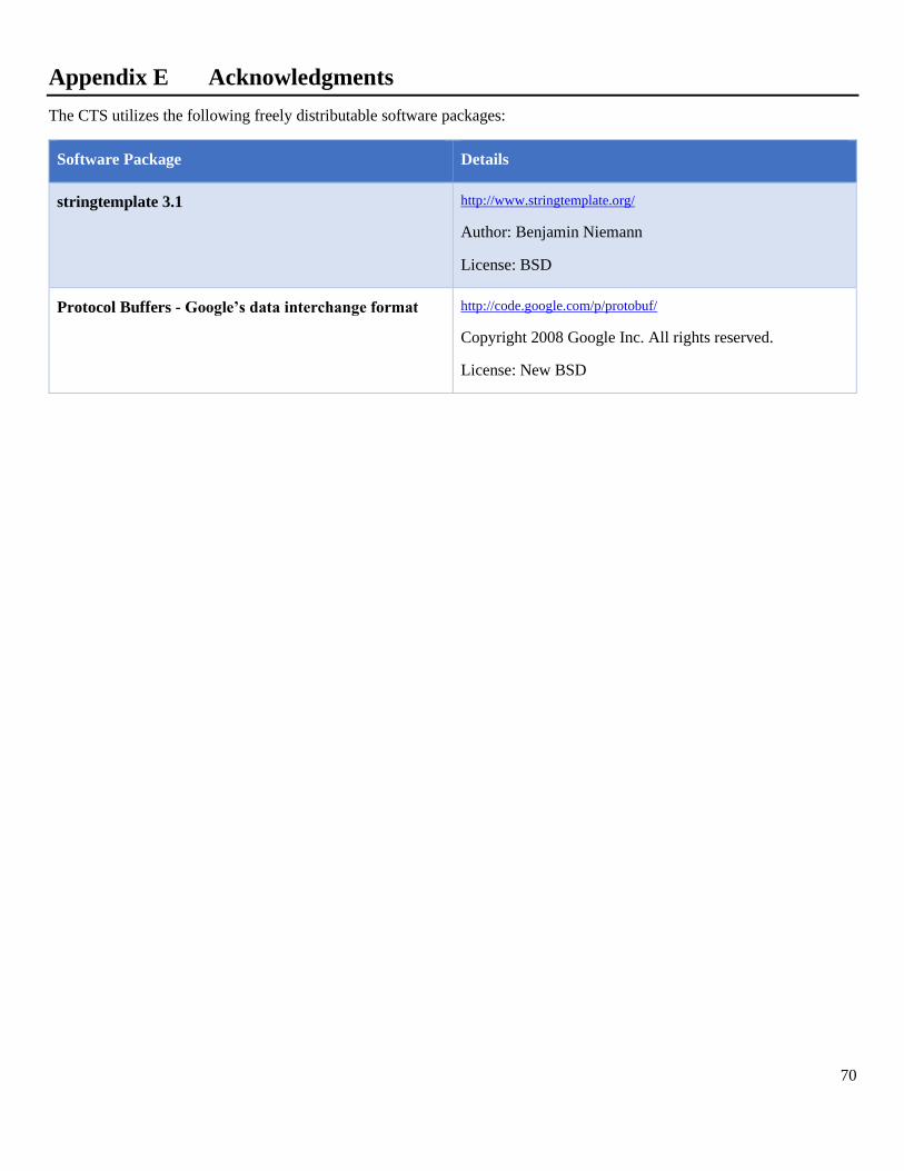
70
Appendix E Acknowledgments
The CTS utilizes the following freely distributable software packages:
Software Package Details
stringtemplate 3.1 http://www.stringtemplate.org/
Author: Benjamin Niemann
License: BSD
Protocol Buffers - Google’s data interchange format http://code.google.com/p/protobuf/
Copyright 2008 Google Inc. All rights reserved.
License: New BSD