Embed Size (px)
Citation preview
Configuring VXLANs
This chapter contains the following sections:
• Information About VXLAN, page 1
• Guidelines and Limitations for VXLAN, page 8
• Enabling VXLAN, page 11
• Configuring a VNI, page 12
• Configuring a Network Virtualization Endpoint Interface, page 12
• Configuring a Switch in the Store-and-Forward Mode, page 13
• Disabling VXLAN, page 13
• Verifying VXLAN Configuration, page 14
• Example of VXLAN Bridging Configuration, page 15
Information About VXLANYou can use Virtual Extensible Local Area Networks (VXLANs) to extend reachability of a VLAN within adata center over Layer 3. When you use VXLANs, you are no longer restricted to using only 4096 VLANsin a data center.
A Layer 2 VLAN is mapped into a larger (24-bit) ID VXLAN Network Identifier (VNI). All frames on thatVLAN are encapsulated in an IP/UDP frame for transport. An additional VXLAN header is added to carrythe VNI information. The VNI identifies the Layer 2 segment that the frame belongs to and is used to definea much larger Layer 2 broadcast domain for that frame. Typically, a Layer 2 domain (VLAN) confines theVM's mobility. With a VXLAN, the Layer 2 domain is extended throughout the data center, increasing theVM's mobility by extending the Layer 2 broadcast domain across Layer 3. The 24-bit VNI provides for about16 million different Layer 2 segments that support a large number of tenants, and their VLANs, in a multitenantdata center.
VXLAN Layer 2 Gateway
A VXLAN gateway is a device that encapsulates a classical Ethernet (CE) frame into a VXLAN frame anddecapsulates a VXLAN frame into a CE frame. A gateway device transparently provides VXLAN benefitsto the physical hosts and virtual machines. The physical hosts or VMs are completely unaware of VXLAN
Cisco Nexus 5600 Series NX-OS Layer 2 Switching Configuration Guide, Release 7.x OL-31636-01 1
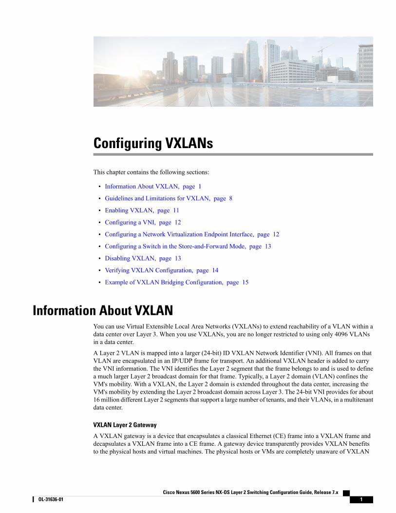
encapsulation. The gateway function can be implemented in a physical network device such as the CiscoNexus 5600 Series Switch or a vSwitch such as the Cisco Nexus 1000V.
Figure 1: VXLAN Gateway Use Cases
VXLAN Router
Similar to traditional routing between different VLANs, a VXLAN router is required for communicationbetween devices that are in different VXLAN segments. The VXLAN router translates frames from one VNIto another. Depending on the source and destination, this process might require decapsulation andreencapsulation of a frame. The Cisco Nexus device supports all combinations of decapsulation, route, andencapsulation. The routing can also be done across native Layer 3 interfaces and VXLAN segments.
You can enable VXLAN routing at the aggregation layer or on Cisco Nexus device aggregation nodes. Thespine only forwards based IP and ignores the encapsulated packets. To help scaling, a few leaf nodes (a pairof border leaves) perform routing between VNIs. A set of VNIs can be grouped into a virtual routing andforwarding (VRF) instance (tenant VRF) to enable routing among those VNIs. If routing must be enabledamong a large number of VNIs, you might need to split the VNIs between several VXLAN routers. Eachrouter is responsible for a set of VNIs and a respective subnet. Redundancy is achieved with FHRP.
Cisco Nexus 5600 Series NX-OS Layer 2 Switching Configuration Guide, Release 7.x2 OL-31636-01
Configuring VXLANsInformation About VXLAN
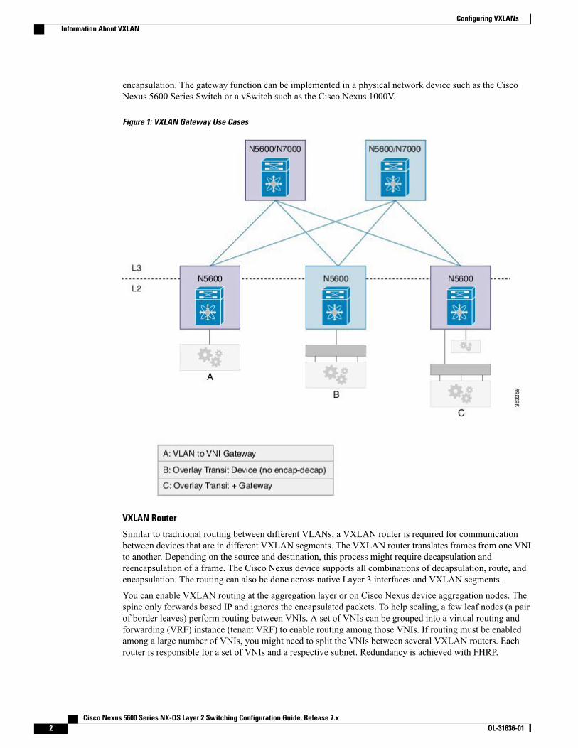
The following figure shows a configuration example with two Cisco Nexus leaf nodes (each node is a virtualport channel [vPC] pair) that acts as VXLAN routers. Node A routes VNIs 1 to 100 while node B routes VNIs201 to 300. You must configure a separate VNI (555) per tenant VRF to carry traffic between VXLAN routersand for routing protocols to exchange routing information between the VXLAN routers.
Figure 2: VXLAN Router Configuration
The figure shows two flows. vni-1 to vni-201 and vni-20 to vni-8.
1 vni-1 to vni-201 : The packet in vNI1 at G1 is sent to the default router for vni-1 (L1 and L2). The routerfinds that the destination address is in vni-201 which is reachable over interface vni-555. The packet isencapsulated with vni-555 and sent to the L3 and L4 pair. The router pair (L3 and L4) routes the packetfrom vni-555 to vni-201 where the final destination is reachable. The packet is then sent to G2, which usesvni-201 to be delivered to the final destination. This packet takes two router hops.
2 vni-20 to > vni-8: The packet at G3 in vni-20 is sent to the default router (L1 and L2). The final destinationis reachable on vni-8. Router (L1 and L2) reencapsulates the packet with vni-8 and sends it to G1 wherethe final destination resides.
Any packet that originates in vni 1 to 100, but is destined to go outside of its VNI, must come to node A toget routed. Similarly, any packet delivered to vni 201 to 300 whose source is different from the destinationVNI is routed into its destination VNI on node B. Packets from vni-1 to vni-201 take two hops (the first hopon node A and the second on node B).
The traffic that is routed between a VNI and outside (nonvirtualized) world might have to go through anexternal router that is connected to the VXLAN router. This router might need to provide Network AddressTranslation (NAT) and firewall services as well.
Cisco Nexus 5600 Series NX-OS Layer 2 Switching Configuration Guide, Release 7.x OL-31636-01 3
Configuring VXLANsInformation About VXLAN
The VXLAN routers can use any routing protocol, for example Open Shortest Path First (OSPF), for routingwithin the tenant VRF. The routers must form neighbor adjacencies over the transit-VNI, because the tenantVRFs are not visible in the core. The core routers only know about the underlay VRF that is used for routingthe packets between VXLAN Tunnel Endpoints (VTEPs) that are based on the outer header.
VXLAN Overlay Network for Broadcast/Unknown-Unicast/Multicast Overlay Traffic
All broadcast/unknown-unicast/multicast overlay traffic must be sent to multiple VTEPs. To identify all theVTEPs that are interested in traffic for a specific VNI, VTEPs build a multicast tree which is identified as theVXLAN Overlay Network for each VNI. This is achieved by mapping the VNI to a multicast group on allthe VTEPs that are interested in the VNI. A multicast tree is built using the PIM protocol and all non-unicasttraffic is distributed to all the interested VTEPs that join the multicast tree. This is achieved by mapping anygiven VNI to a multicast group address, which is also called the Delivery Group (DG) for that VNI. WhenVTEP sends a non-unicast packet on a VNI over the overlay network, the packet is encapsulated in a VXLANheader and is sent to the DG address instead of sending it to single destination VTEP IP address as in the caseof unicast traffic. The VXLAN encapsulated packets destined to the DG get routed in the overlay network byusing the PIM tree built for the DG . All the VTEPs that join the PIM tree built for that DG receive the traffic.
Cisco Nexus devices use PIM BIDIR only to build this VXLAN Overlay Network. PIM ASM/SSM is notsupported currently, so any multicast group defined as DG to carry VXLAN overlay traffic for a VNI mustalways be defined as a BIDIR group. The rendezvous point (RP) for this BIDIR group can be anywhere inthe Layer 3 overlay network. Multiple VNIs can map to the same DG, and so the overlay traffic for theseVNIs is sent across the Overlay Network using the same PIM BIDIR tree. Cisco Nexus devices can supporta maximum of 200 DGs on a given VTEP.
VXLAN Multicast Routing
You can configure the VXLAN router as a multicast router for inner (user) multicast groups. Multicast routingmust be configured within a tenant VRF. The multicast routing protocol for the inner groups does not haveto be PIM BIDIR even though PIM BIDIR is used for the outer multicast. The inner multicast group can usePIM-Any Source Multicast (ASM), ASM, or BIDIR as supported by the platform. If VTEP is a part of a vPCpair, the inner group cannot be a BIDIR group. In a vPC setup, BIDIR can be used only as a DG to build theVXLAN overlay network and cannot be used to carry inner multicast traffic. Similar to VXLAN unicastrouting, multicast routing is done among the VNI interfaces that are in a tenant VRF. The VXLAN gatewaynodes deliver the multicast data and control frames to the VXLAN multicast router using an outer deliverygroup (DG).
PIM routers for the inner multicast group exchange the PIM messages over a VXLAN network that connectsthem on all VNIs that are part of the tenant VRF.
Cisco Nexus Device OverlaysThe following figure shows a topology with a virtual port channel (vPC), fabric extenders (FEXes), VXLANhypervisors, and gateway ports that are supported by the Cisco Nexus device. All FEX topologies (AA-FEX,ST-FEX, and 2LvPC) are supported.
Cisco Nexus 5600 Series NX-OS Layer 2 Switching Configuration Guide, Release 7.x4 OL-31636-01
Configuring VXLANsCisco Nexus Device Overlays
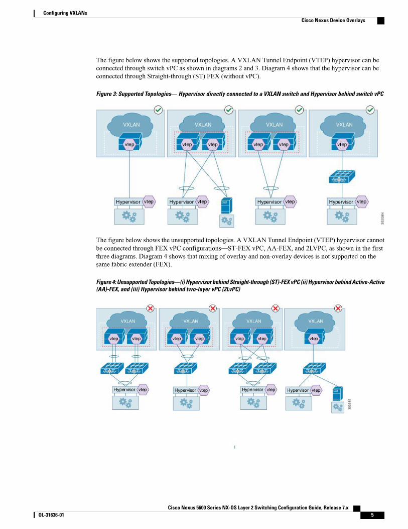
The figure below shows the supported topologies. A VXLAN Tunnel Endpoint (VTEP) hypervisor can beconnected through switch vPC as shown in diagrams 2 and 3. Diagram 4 shows that the hypervisor can beconnected through Straight-through (ST) FEX (without vPC).
Figure 3: Supported Topologies— Hypervisor directly connected to a VXLAN switch and Hypervisor behind switch vPC
The figure below shows the unsupported topologies. A VXLAN Tunnel Endpoint (VTEP) hypervisor cannotbe connected through FEX vPC configurations—ST-FEX vPC, AA-FEX, and 2LVPC, as shown in the firstthree diagrams. Diagram 4 shows that mixing of overlay and non-overlay devices is not supported on thesame fabric extender (FEX).
Figure 4: Unsupported Topologies—(i) Hypervisor behind Straight-through (ST)-FEX vPC (ii) Hypervisor behind Active-Active(AA)-FEX, and (iii) Hypervisor behind two-layer vPC (2LvPC)
Cisco Nexus 5600 Series NX-OS Layer 2 Switching Configuration Guide, Release 7.x OL-31636-01 5
Configuring VXLANsCisco Nexus Device Overlays
VXLAN Tunnel EndpointA VXLAN Tunnel Endpoint (VTEP) performs the VXLAN gateway function. A VTEP is represented as aninterface in the Cisco NX-OS. All VTEPs are managed by the VXLAN manager. The Cisco Nexus devicerequires one VTEP for each encapsulation type.
VTEP IP Addresses and VRF Instances
Each VTEP must have at least one IP address. This IP address is used for encapsulation or decapsulation. ForvPC configurations, a separate IP address is used for encapsulation or decapsulation of the traffic to and fromvPC connected hosts. The emulated IP address must be the same on both switches in a vPC pair. The emulatedIP address allows the network to load balance the traffic destined to the vPC-connected devices without usingMCT. Similarly, a distinct non-emulated IP address that is used for encapsulation or decapsulation for a singlyconnected host ensures that traffic to that host arrives on the correct switch in the pair without going througha vPC Peer-Link, also known as Multichassis EtherChannel Trunk (MCT).
The VRF instance specified for the VTEP carries all the encapsulated traffic within the data center.
The Cisco Nexus device supports a single infrastructure (infra)-VRF andmultiple tenant VRFs. The infra-VRFcarries the VXLAN traffic through the core Layer 3 network. A tenant VRF is not visible to the routing devicesin the core. The tenant VRFs are used by VXLAN routers. The Cisco Nexus device supports the default VRFas the infra-VRF.
VTEP IP Multicast Addresses
A VXLAN gateway uses an IP delivery group (DG) to flood multidestination frames within a VNI. Layer 2broadcast, unknown unicast, and multicast frames are flooded to other VTEPs using the IP multicast DGaddress. Only one flood-DG address can be used per VNI. To reduce the amount of BUM traffic that reachesall VTEPs, each VNI should be given its own DG address so that the flood domain is contained within theVTEPs that are a gateway for the VNI. The number of VNIs might exceed the distinct DG trees that can besupported by the network. In that case, multiple VNIs must share a DG address for flooding. The user (inneror overlay) multicast frames are also encapsulated using a DG.
VXLAN Tunnel Endpoint Peers
VTEP-Peer Learning
The Cisco Nexus device discovers VXLAN Tunnel Endpoint Peers (VTEPs) using the flood-and-learntechnique which is when a VTEP peer is learned when the first VXLAN encapsulated packet is received fromthe peer.
A gateway device must identify only those VTEP peers that support any of the locally configured VNIs ordelivery groups (DG).
The Cisco Nexus device has the capability to snoop unicast, as well as, multicast packets sent by unknownpeers. If an unknownVTEP-peer sends packets using any of the multicast DGs configured locally, a notificationis received from the hardware, which provides the information about the new peer. In addition to monitoringthe multicast DG addresses, the Cisco Nexus device also monitors frames sent to its own VTEP addresses.The multicast and unicast frames snooped by the hardware are not de-capsulated until the sender is a knownVTEP-peer.
Cisco Nexus 5600 Series NX-OS Layer 2 Switching Configuration Guide, Release 7.x6 OL-31636-01
Configuring VXLANsVXLAN Tunnel Endpoint
The VXLAN manager adds the sender VTEP as a new peer. After the VTEP peer is added in the hardware,the hardware would then stop sending the VTEP peer discovery notification for it.
Due to the sharing of DG addresses, the VNI in the packet might not be configured as a gateway VNI. In thatcase, the VTEP peer avoids further VTEP peer discovery indications.
VTEP-Peer Aging/Removal
AVTEP-peer might shut down, be removed from the network, become unreachable, or just become dormant.In many situations, there is no direct indication to remove the VTEP-peer. Therefore, you must employ anaging mechanism to clean up the VTEP peers that were dynamically learned. The cleanup is essential becausethe total number of active VTEP peers present at any given time is limited by the hardware. The ageout timeis set to 10 minutes.
vPC Considerations
vPC Consistency Checks
DescriptionvPC Check TypeParameter
Brings down the affected VLANson vPC ports on both sides.
Type-1—nongracefulVLAN-VNI mapping
Member VNIs must be the sameon both nodes. VNIs that are notcommon bring down thecorresponding VLANs on vPCports on both sides.
Type-1—nongracefulVTEP-Member-VNI
If an emulated IP address is not thesame on both nodes, all gatewayvPC ports on one side (secondary)are brought down. Alternatively,one side of all vPC ports is broughtdown.
Type-1—gracefulVTEP-emulated IP
vPC manager issues a warning.Type 2VTEP-node IP address
vPC and Multicast
For each outer destination group (DG), youmust select one of the vPC peers as a designated Affinity Forwarder(AF). The AF switch forwards the multidestination traffic to the vPC connected devices while a non-AF switchonly forwards traffic to singly connected devices. The selection of an AF is done by a multicast group that isbased on a vPC permanent role.
Cisco Nexus 5600 Series NX-OS Layer 2 Switching Configuration Guide, Release 7.x OL-31636-01 7
Configuring VXLANsvPC Considerations
QoS/ACL SupportQuality of Service (QoS) and Access Control Lists (ACLs) are applied to the ingress packets for packets fromVLAN to VXLAN (encapsulation). During encapsulation, the outer Class of Service (CoS) and differentiatedservices code point (DSCP) values are derived from the final inner COS and DSCP values. When a packet isdecapsulated, the outer CoS is used as the inner CoS, because there is no inner .1Q, or .1P tag carried withthe inner frame. The rest of the processing is done on the inner frame.
If traffic is decapsulated and reencapsulated, the inner CoS value is used to derive the outer DSCP value. TheCoS is preserved from the ingress frame.
For overlay transit traffic (traffic that is not decapsulated), QoS and ACLs are applied to the outer headers.
TTL HandlingWhen a native classical Ethernet (CE) packet is encapsulated, the outer Time To Live (TTL) is selected basedon a configured value. The default is 32. The outer TTL is decremented based on the outer IP routing anddiscarded when it goes to zero. The inner TTL is unchanged as the packet traverses the overlay network. Afterdecapsulation, the inner TTL is preserved if the inner packet is Layer 2 switched. The inner TTL is decrementedwhenever an inner packet is routed.
When a multicast packet is decapsulated and reencapsulated, the outer TTL is decremented by 1 while theinner TTL is preserved. If the inner packet is multicast routed, the inner TTL is decremented whenever anunencapsulated inner packet is delivered to the end station.
Multipathing SupportWhen a CE packet is encapsulated using VXLAN encapsulation, a 16-bit hash value is created using the Layer2 and Layer 3 addresses and Layer 4 source and destination ports if available. The hash value is then used asan outer UDP src_port. This hash value represents the inner-packet flow (with some aliasing due to the 16-bithash result). The outer UDP source port is used by core routers to load balance traffic between two VTEPsbased on inner flows.
When the packet is first encapsulated, inner packet headers are used to select one of many available equalcost paths to the destination VTEP.
MTUThe Cisco Nexus device does not support fragmentation or re-assembly of VXLAN traffic. As VXLANencapsulation adds 50 bytes to the packet, the MTU of the tenant devices must be at least 50 bytes smallerthan theMTU of the network devices. The Cisco VXLAN device supports anMTU configuration on a physicalinterface as well as an SVI interface. Ensure that the MTU on the VNI-mapped SVI is 50 bytes smaller thanthe physical interfaces'sMTUwhen configuring VXLAN routing. For a VXLANLayer 2 gateway, the defaultMTU is 1500. The recommended method is to increase the MTU to 1550.
Guidelines and Limitations for VXLANThe VXLAN configuration guidelines and limitations are as follows:
Cisco Nexus 5600 Series NX-OS Layer 2 Switching Configuration Guide, Release 7.x8 OL-31636-01
Configuring VXLANsQoS/ACL Support
• A VXLAN device must be configured in the store-and-forward mode.
• The classical Ethernet (CE) packet on an edge interface is mapped to a VNI based on the VLAN towhich it is associated. The VLAN to Virtual Network Identifier (VNI) mapping is created under theVLAN configuration, which limits the number of supported VNIs on a switch to 4000.
• The multicast delivery group used to build the VXLAN overlay network for VNIs must be configuredas a Protocol-Independent Multicast (PIM) Bidirectional (BIDIR) group. The VXLAN overlay networkcannot be built using PIM SM or PIM SSM.
• PIM-BDIR in a vPC configuration for non-VXLAN traffic is not supported.
• The Cisco Nexus device does not support Layer 3 links on southbound interfaces that are connected toa fabric extender (FEX).
• Only loopback interfaces are supported as the source interface for the NVE interface. under an NetworkVirtualization Edge (NVE) configuration. NVE is equal to VTEP.
• For any protocols that work over inner switched virtual interfaces (SVIs), you should increase themaximum transmission unit (MTU) of that SVI by 50 to allow VXLAN encapsulation. If you use thedefault MTU, you might get unexpected results.
• A VXLAN Tunnel Endpoint (VTEP) hypervisor cannot be connected through Straight-Through FEX(ST-FEX-VPC), Active-Active FEX (AA-FEX), and 2-Layer vPC.
• The Cisco Nexus device can only support Layer 3 routed port links to carry overlay traffic to the core.
• A Layer 2 trunk cannot be used to carry overlay traffic to the core. Layer 2 trunks with SVIs can be usedon southbound interfaces that connect to hypervisors. The overlay traffic that originates to and fromhypervisors is carried using an SVI.
• The IP routing protocol must be configured for the underlay network.
• PIM-BIDIR multicast routing must be configured for the underlay network.
• The vn-segment-vlan-based feature must be configured on the VXLAN gateway and router devices.
• IGMP snooping is not supported on VXLAN VLANs.
• Hypervisor VTEPs (such as Cisco Nexus 1000V) cannot be connected using Layer 3 interfaces. Theymust be connected through Layer 2 interfaces.
• Only one NVE interface is supported on a switch.
• SNMP is not supported on the NVE interface.
• Policy-based routing (PBR) is not supported for tenant traffic.
• Ingress and egress ACLs cannot be applied to the outer header of the VXLAN packet on the VXLANgateway device.
• A physical port cannot be used as a tenant (gateway) port and overlay port at the same time.
Note • Gateway Port—Physical port on which VLAN-VNI mapping is configured.
• Overlay Port—Encapsulated traffic is received and sent on an overlay port. Thisincludes the core (network) facing ports as well as local edge ports where VTEPs(hypervisors) are connected.
Cisco Nexus 5600 Series NX-OS Layer 2 Switching Configuration Guide, Release 7.x OL-31636-01 9
Configuring VXLANsGuidelines and Limitations for VXLAN
• The maximum transmission unit (MTU) must configured throughout the network to accommodate 50bytes of VXLAN encapsulation.
• Tenant ports and overlay ports that connect to VTEP hypervisors cannot be on the same fabric extender(FEX).
•When you are connecting VTEP hypervisors to FEX ports, all VTEP hypervisors that are connected toa FEX must use the same outer VLAN.
• Refer to supported and un-supported topology diagrams when connecting hosts and VTEP hypervisorsto a Cisco Nexus device.
• Configured store and forward mode with reload.
• Connecting hypervisors with different overlay encapsulation to the same FEX is not allowed.
• VLAN 1 cannot be used to carry VXLAN traffic.
• There is no support for originating Hot Standby Router Protocol (HSRP) packets with the source MACas a user-configured HSRP MAC. Support is limited to using standard HSRP MAC addresses (v1 andv2) as the source MAC addresses for HSRP packets.
• The show interface nve 1 counters command does not display statistics of VXLAN incoming andoutgoing packets.
• DHCP snooping on VXLAN-enabled VLANs is not supported.
vPC Considerations
• A virtual IP must be configured for the vPC pair
• A virtual IP must be configured for loopback purposes.
• A peer-link switched virtual interfaces (SVI) must be only on a peer-link in external communication. Aconfiguration example:
vpc nve peer-link-vlan 99
interface vlan99
no shutdown
no ip redirects
ip address 99.1.1.1/24
ip ospf cost 10
ip router ospf 1 area 0.0.0.0
ip pim sparse-mode
• A special peer-link SVI must be configured on the VPC pair.
• VPC peers must have identical configurations:
◦Consistent VLAN to VN-segment mapping.
◦Consistent NVE1 binding to the same loopback interface.
◦Using the same secondary IP address.
◦Using different primary IP addresses.
Cisco Nexus 5600 Series NX-OS Layer 2 Switching Configuration Guide, Release 7.x10 OL-31636-01
Configuring VXLANsGuidelines and Limitations for VXLAN
◦Consistent VNI to group mapping.
• A VTEP hypervisor cannot be connected to AA-FEX, EVPC, or ST-FEX vPC.
• Supports a line-rate encapsulation or decapsulation of VXLAN switched traffic.
VXLAN introduces a 50-byte overhead to the original packet due to VXLANencapsulation. For example, for a 1000 byte packet, there is a 5% overhead per packet.Overhead varies depending on the packet size and it is expected for VXLAN.
Note
Enabling VXLANBefore You Begin
You must configure underlay and PIM-bidir multicast.
Configure the switch in the store-and-forward mode. See Configuring a Switch in the Store-and-ForwardMode, on page 13.
Procedure
PurposeCommand or Action
Enters global configuration mode.switch# configure terminalStep 1
Enables NV overlay.switch(config)# feature nv overlayStep 2
Enables the VN-Segment feature on the switch.switch(config)# featurevn-segment-vlan-based
Step 3
(Optional)Saves the change persistently through reboots andrestarts by copying the running configuration tothe startup configuration.
switch(config)# copy running-configstartup-config
Step 4
This example shows how to enable VXLAN:switch# configure terminalswitch(config)# feature nv overlayswitch(config)# feature vn-segment-vlan-based
Cisco Nexus 5600 Series NX-OS Layer 2 Switching Configuration Guide, Release 7.x OL-31636-01 11
Configuring VXLANsEnabling VXLAN
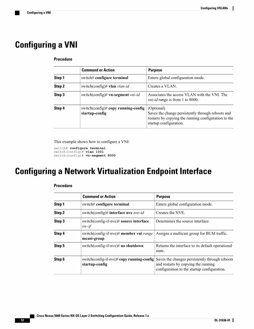
Configuring a VNIProcedure
PurposeCommand or Action
Enters global configuration mode.switch# configure terminalStep 1
Creates a VLAN.switch(config)# vlan vlan-idStep 2
Associates the access VLAN with the VNI. Thevni-id range is from 1 to 8000.
switch(config)# vn-segment vni-idStep 3
(Optional)Saves the change persistently through reboots andrestarts by copying the running configuration to thestartup configuration.
switch(config)# copy running-configstartup-config
Step 4
This example shows how to configure a VNI:switch# configure terminalswitch(config)# vlan 1001switch(config)# vn-segment 8000
Configuring a Network Virtualization Endpoint InterfaceProcedure
PurposeCommand or Action
Enters global configuration mode.switch# configure terminalStep 1
Creates the NVE.switch(config)# interface nve nve-idStep 2
Determines the source interface.switch(config-if-nve)# source interfacesrc-if
Step 3
Assigns a multicast group for BUM traffic.switch(config-if-nve)#member vni rangemcast-group
Step 4
Returns the interface to its default operationalstate.
switch(config-if-nve)# no shutdownStep 5
Saves the changes persistently through rebootsand restarts by copying the runningconfiguration to the startup configuration.
switch(config-if-nve)# copy running-configstartup-config
Step 6
Cisco Nexus 5600 Series NX-OS Layer 2 Switching Configuration Guide, Release 7.x12 OL-31636-01
Configuring VXLANsConfiguring a VNI
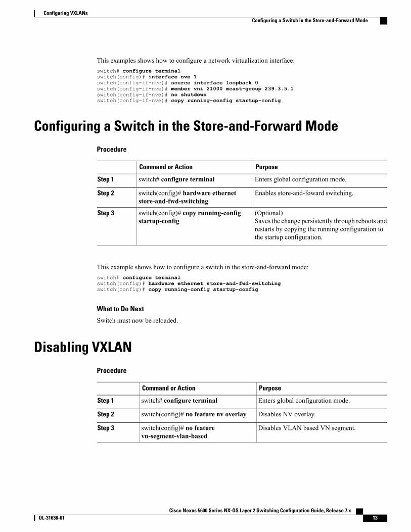
This examples shows how to configure a network virtualization interface:switch# configure terminalswitch(config)# interface nve 1switch(config-if-nve)# source interface loopback 0switch(config-if-nve)# member vni 21000 mcast-group 239.3.5.1switch(config-if-nve)# no shutdownswitch(config-if-nve)# copy running-config startup-config
Configuring a Switch in the Store-and-Forward ModeProcedure
PurposeCommand or Action
Enters global configuration mode.switch# configure terminalStep 1
Enables store-and-foward switching.switch(config)# hardware ethernetstore-and-fwd-switching
Step 2
(Optional)Saves the change persistently through reboots andrestarts by copying the running configuration tothe startup configuration.
switch(config)# copy running-configstartup-config
Step 3
This example shows how to configure a switch in the store-and-forward mode:switch# configure terminalswitch(config)# hardware ethernet store-and-fwd-switchingswitch(config)# copy running-config startup-config
What to Do Next
Switch must now be reloaded.
Disabling VXLANProcedure
PurposeCommand or Action
Enters global configuration mode.switch# configure terminalStep 1
Disables NV overlay.switch(config)# no feature nv overlayStep 2
Disables VLAN based VN segment.switch(config)# no featurevn-segment-vlan-based
Step 3
Cisco Nexus 5600 Series NX-OS Layer 2 Switching Configuration Guide, Release 7.x OL-31636-01 13
Configuring VXLANsConfiguring a Switch in the Store-and-Forward Mode
PurposeCommand or Action
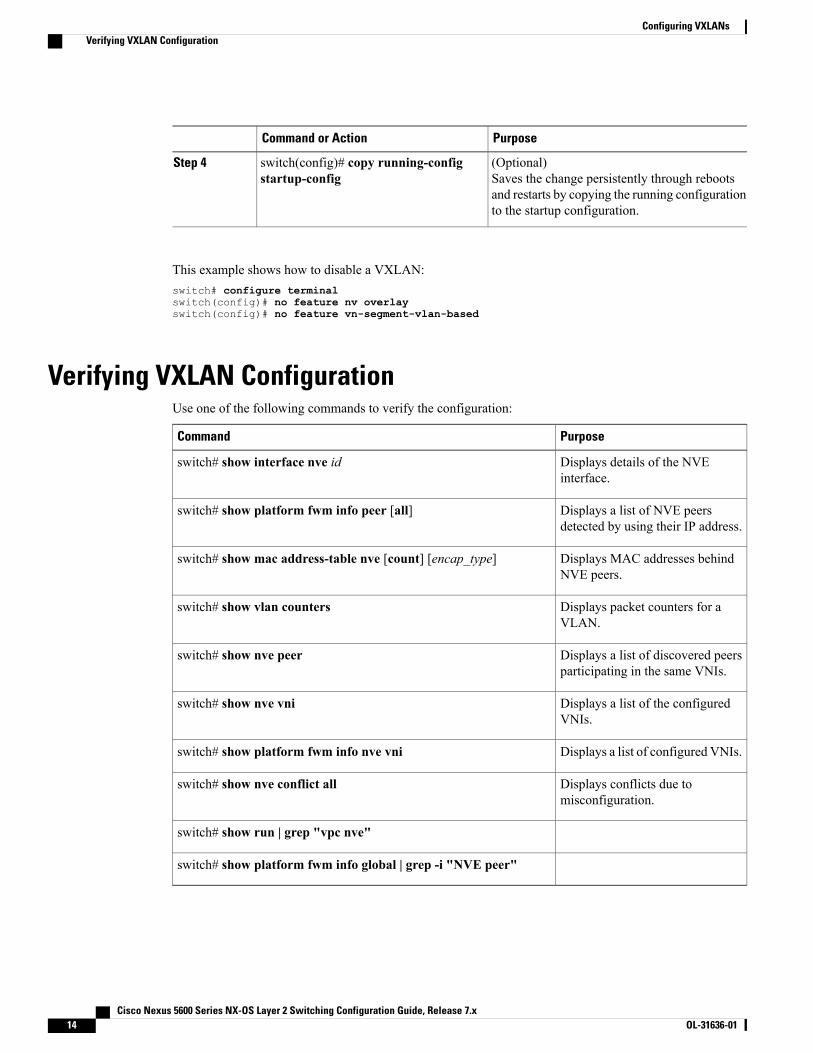
(Optional)Saves the change persistently through rebootsand restarts by copying the running configurationto the startup configuration.
switch(config)# copy running-configstartup-config
Step 4
This example shows how to disable a VXLAN:switch# configure terminalswitch(config)# no feature nv overlayswitch(config)# no feature vn-segment-vlan-based
Verifying VXLAN ConfigurationUse one of the following commands to verify the configuration:
PurposeCommand
Displays details of the NVEinterface.
switch# show interface nve id
Displays a list of NVE peersdetected by using their IP address.
switch# show platform fwm info peer [all]
Displays MAC addresses behindNVE peers.
switch# show mac address-table nve [count] [encap_type]
Displays packet counters for aVLAN.
switch# show vlan counters
Displays a list of discovered peersparticipating in the same VNIs.
switch# show nve peer
Displays a list of the configuredVNIs.
switch# show nve vni
Displays a list of configured VNIs.switch# show platform fwm info nve vni
Displays conflicts due tomisconfiguration.
switch# show nve conflict all
switch# show run | grep "vpc nve"
switch# show platform fwm info global | grep -i "NVE peer"
Cisco Nexus 5600 Series NX-OS Layer 2 Switching Configuration Guide, Release 7.x14 OL-31636-01
Configuring VXLANsVerifying VXLAN Configuration
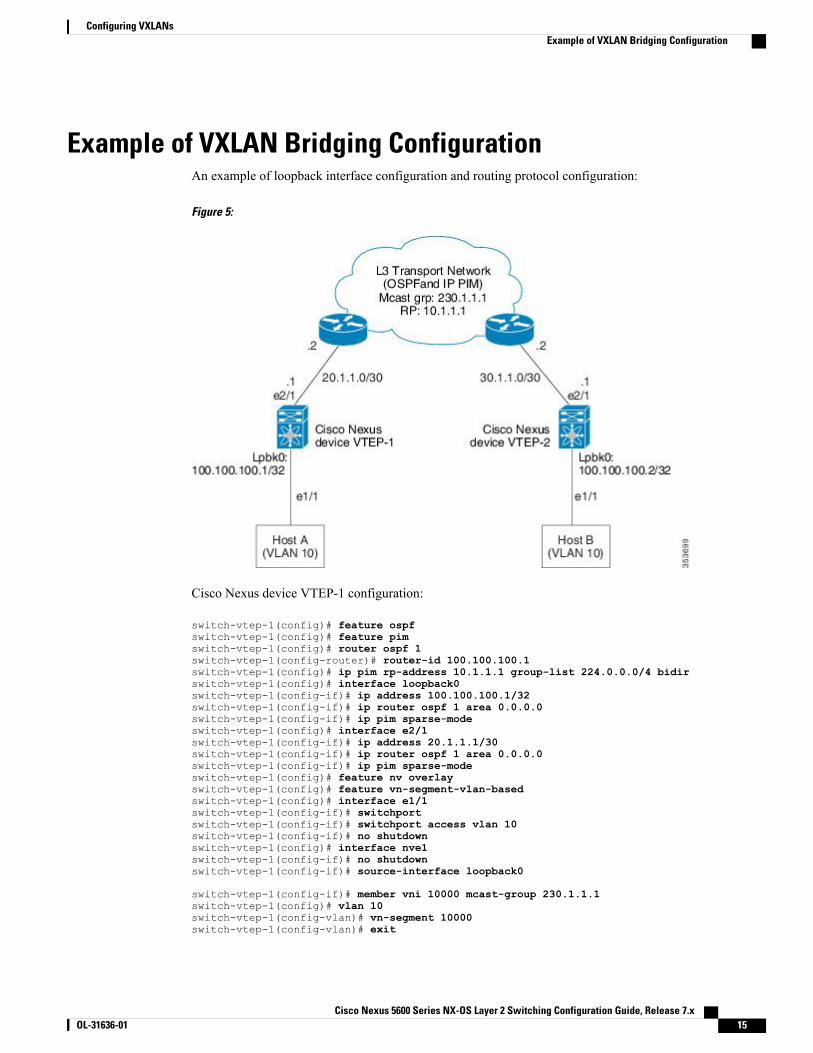
Example of VXLAN Bridging ConfigurationAn example of loopback interface configuration and routing protocol configuration:
Figure 5:
Cisco Nexus device VTEP-1 configuration:
switch-vtep-1(config)# feature ospfswitch-vtep-1(config)# feature pimswitch-vtep-1(config)# router ospf 1switch-vtep-1(config-router)# router-id 100.100.100.1switch-vtep-1(config)# ip pim rp-address 10.1.1.1 group-list 224.0.0.0/4 bidirswitch-vtep-1(config)# interface loopback0switch-vtep-1(config-if)# ip address 100.100.100.1/32switch-vtep-1(config-if)# ip router ospf 1 area 0.0.0.0switch-vtep-1(config-if)# ip pim sparse-modeswitch-vtep-1(config)# interface e2/1switch-vtep-1(config-if)# ip address 20.1.1.1/30switch-vtep-1(config-if)# ip router ospf 1 area 0.0.0.0switch-vtep-1(config-if)# ip pim sparse-modeswitch-vtep-1(config)# feature nv overlayswitch-vtep-1(config)# feature vn-segment-vlan-basedswitch-vtep-1(config)# interface e1/1switch-vtep-1(config-if)# switchportswitch-vtep-1(config-if)# switchport access vlan 10switch-vtep-1(config-if)# no shutdownswitch-vtep-1(config)# interface nve1switch-vtep-1(config-if)# no shutdownswitch-vtep-1(config-if)# source-interface loopback0
switch-vtep-1(config-if)# member vni 10000 mcast-group 230.1.1.1switch-vtep-1(config)# vlan 10switch-vtep-1(config-vlan)# vn-segment 10000switch-vtep-1(config-vlan)# exit
Cisco Nexus 5600 Series NX-OS Layer 2 Switching Configuration Guide, Release 7.x OL-31636-01 15
Configuring VXLANsExample of VXLAN Bridging Configuration
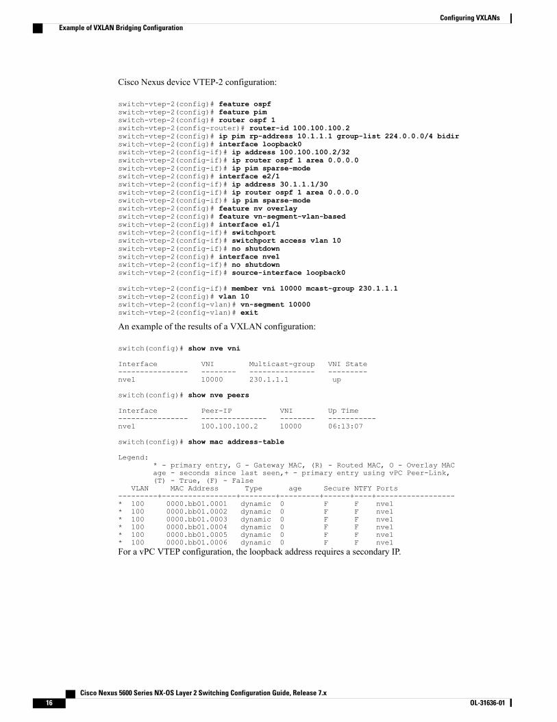
Cisco Nexus device VTEP-2 configuration:
switch-vtep-2(config)# feature ospfswitch-vtep-2(config)# feature pimswitch-vtep-2(config)# router ospf 1switch-vtep-2(config-router)# router-id 100.100.100.2switch-vtep-2(config)# ip pim rp-address 10.1.1.1 group-list 224.0.0.0/4 bidirswitch-vtep-2(config)# interface loopback0switch-vtep-2(config-if)# ip address 100.100.100.2/32switch-vtep-2(config-if)# ip router ospf 1 area 0.0.0.0switch-vtep-2(config-if)# ip pim sparse-modeswitch-vtep-2(config)# interface e2/1switch-vtep-2(config-if)# ip address 30.1.1.1/30switch-vtep-2(config-if)# ip router ospf 1 area 0.0.0.0switch-vtep-2(config-if)# ip pim sparse-modeswitch-vtep-2(config)# feature nv overlayswitch-vtep-2(config)# feature vn-segment-vlan-basedswitch-vtep-2(config)# interface e1/1switch-vtep-2(config-if)# switchportswitch-vtep-2(config-if)# switchport access vlan 10switch-vtep-2(config-if)# no shutdownswitch-vtep-2(config)# interface nve1switch-vtep-2(config-if)# no shutdownswitch-vtep-2(config-if)# source-interface loopback0
switch-vtep-2(config-if)# member vni 10000 mcast-group 230.1.1.1switch-vtep-2(config)# vlan 10switch-vtep-2(config-vlan)# vn-segment 10000switch-vtep-2(config-vlan)# exit
An example of the results of a VXLAN configuration:
switch(config)# show nve vni
Interface VNI Multicast-group VNI State---------------- -------- --------------- ---------nve1 10000 230.1.1.1 up
switch(config)# show nve peers
Interface Peer-IP VNI Up Time---------------- --------------- -------- -----------nve1 100.100.100.2 10000 06:13:07
switch(config)# show mac address-table
Legend:* - primary entry, G - Gateway MAC, (R) - Routed MAC, O - Overlay MACage - seconds since last seen,+ - primary entry using vPC Peer-Link,(T) - True, (F) - False
VLAN MAC Address Type age Secure NTFY Ports---------+-----------------+--------+---------+------+----+------------------* 100 0000.bb01.0001 dynamic 0 F F nve1* 100 0000.bb01.0002 dynamic 0 F F nve1* 100 0000.bb01.0003 dynamic 0 F F nve1* 100 0000.bb01.0004 dynamic 0 F F nve1* 100 0000.bb01.0005 dynamic 0 F F nve1* 100 0000.bb01.0006 dynamic 0 F F nve1For a vPC VTEP configuration, the loopback address requires a secondary IP.
Cisco Nexus 5600 Series NX-OS Layer 2 Switching Configuration Guide, Release 7.x16 OL-31636-01
Configuring VXLANsExample of VXLAN Bridging Configuration
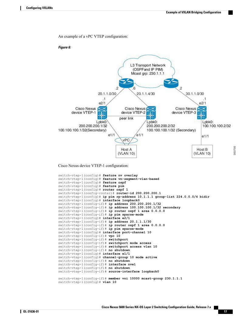
An example of a vPC VTEP configuration:
Figure 6:
Cisco Nexus device VTEP-1 configuration:
switch-vtep-1(config)# feature nv overlayswitch-vtep-1(config)# feature vn-segment-vlan-basedswitch-vtep-1(config)# feature ospfswitch-vtep-1(config)# feature pimswitch-vtep-1(config)# router ospf 1switch-vtep-1(config-router)# router-id 200.200.200.1switch-vtep-1(config)# ip pim rp-address 10.1.1.1 group-list 224.0.0.0/4 bidirswitch-vtep-1(config)# interface loopback0switch-vtep-1(config-if)# ip address 200.200.200.1/32switch-vtep-1(config-if)# ip address 100.100.100.1/32 secondaryswitch-vtep-1(config-if)# ip router ospf 1 area 0.0.0.0switch-vtep-1(config-if)# ip pim sparse-modeswitch-vtep-1(config)# interface e2/1switch-vtep-1(config-if)# ip address 20.1.1.1/30switch-vtep-1(config-if)# ip router ospf 1 area 0.0.0.0switch-vtep-1(config-if)# ip pim sparse-modeswitch-vtep-1(config)# interface port-channel 10switch-vtep-1(config-if)# vpc 10switch-vtep-1(config-if)# switchportswitch-vtep-1(config-if)# switchport mode accessswitch-vtep-1(config-if)# switchport access vlan 10switch-vtep-1(config-if)# no shutdownswitch-vtep-1(config)# interface e1/1switch-vtep-1(config)# channel-group 10 mode activeswitch-vtep-1(config-if)# no shutdownswitch-vtep-1(config-if)# interface nve1switch-vtep-1(config-if)# no shutdownswitch-vtep-1(config-if)# source-interface loopback0
switch-vtep-1(config-if)# member vni 10000 mcast-group 230.1.1.1switch-vtep-1(config)# vlan 10
Cisco Nexus 5600 Series NX-OS Layer 2 Switching Configuration Guide, Release 7.x OL-31636-01 17
Configuring VXLANsExample of VXLAN Bridging Configuration
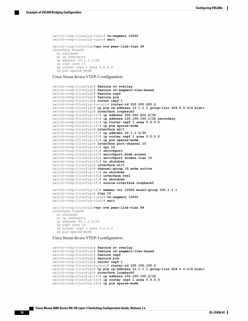
switch-vtep-1(config-vlan)# vn-segment 10000switch-vtep-1(config-vlan)# exit
switch-vtep-1(config)#vpc nve peer-link-vlan 99interface Vlan99no shutdownno ip redirectsip address 99.1.1.1/24ip ospf cost 10ip router ospf 1 area 0.0.0.0ip pim sparse-mode
Cisco Nexus device VTEP-2 configuration:
switch-vtep-2(config)# feature nv overlayswitch-vtep-2(config)# feature vn-segment-vlan-basedswitch-vtep-2(config)# feature ospfswitch-vtep-2(config)# feature pimswitch-vtep-2(config)# router ospf 1switch-vtep-2(config-router)# router-id 200.200.200.2switch-vtep-2(config)# ip pim rp-address 10.1.1.1 group-list 224.0.0.0/4 bidirswitch-vtep-2(config)# interface loopback0switch-vtep-2(config-if)# ip address 200.200.200.2/32switch-vtep-2(config-if)# ip address 100.100.100.1/32 secondaryswitch-vtep-2(config-if)# ip router ospf 1 area 0.0.0.0switch-vtep-2(config-if)# ip pim sparse-modeswitch-vtep-2(config)# interface e2/1switch-vtep-2(config-if)# ip address 20.1.1.5/30switch-vtep-2(config-if)# ip router ospf 1 area 0.0.0.0switch-vtep-2(config-if)# ip pim sparse-modeswitch-vtep-2(config)# interface port-channel 10switch-vtep-2(config-if)# vpc 10switch-vtep-2(config-if)# switchportswitch-vtep-2(config-if)# switchport mode accessswitch-vtep-2(config-if)# switchport access vlan 10switch-vtep-2(config-if)# no shutdownswitch-vtep-2(config)# interface e1/1switch-vtep-2(config)# channel-group 10 mode activeswitch-vtep-2(config-if)# no shutdownswitch-vtep-2(config-if)# interface nve1switch-vtep-2(config-if)# no shutdownswitch-vtep-2(config-if)# source-interface loopback0
switch-vtep-2(config-if)# member vni 10000 mcast-group 230.1.1.1switch-vtep-2(config)# vlan 10switch-vtep-2(config-vlan)# vn-segment 10000switch-vtep-2(config-vlan)# exit
switch-vtep-2(config)#vpc nve peer-link-vlan 99interface Vlan99no shutdownno ip redirectsip address 99.1.1.2/24ip ospf cost 10ip router ospf 1 area 0.0.0.0ip pim sparse-mode
Cisco Nexus device VTEP-3 configuration:
switch-vtep-2(config)# feature nv overlayswitch-vtep-2(config)# feature vn-segment-vlan-basedswitch-vtep-2(config)# feature ospfswitch-vtep-2(config)# feature pimswitch-vtep-2(config)# router ospf 1switch-vtep-2(config-router)# router-id 100.100.100.2switch-vtep-2(config)# ip pim rp-address 10.1.1.1 group-list 224.0.0.0/4 bidirswitch-vtep-2(config)# interface loopback0switch-vtep-2(config-if)# ip address 100.100.100.2/32switch-vtep-2(config-if)# ip router ospf 1 area 0.0.0.0switch-vtep-2(config-if)# ip pim sparse-mode
Cisco Nexus 5600 Series NX-OS Layer 2 Switching Configuration Guide, Release 7.x18 OL-31636-01
Configuring VXLANsExample of VXLAN Bridging Configuration
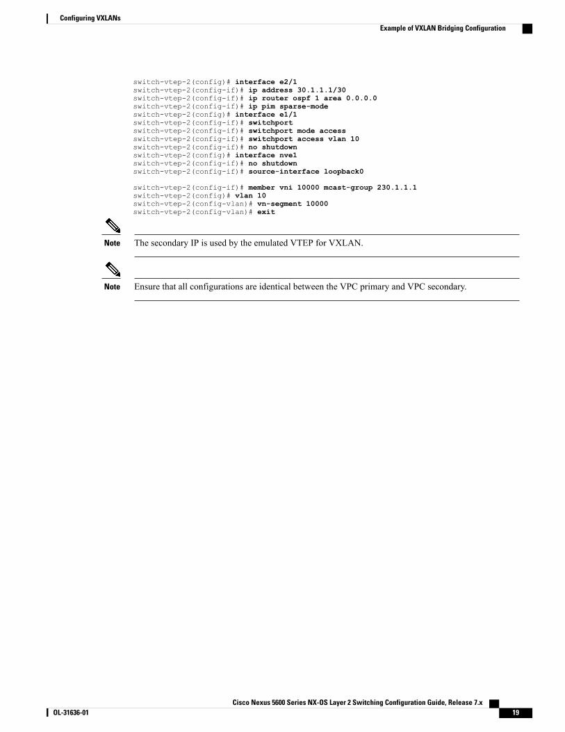
switch-vtep-2(config)# interface e2/1switch-vtep-2(config-if)# ip address 30.1.1.1/30switch-vtep-2(config-if)# ip router ospf 1 area 0.0.0.0switch-vtep-2(config-if)# ip pim sparse-modeswitch-vtep-2(config)# interface e1/1switch-vtep-2(config-if)# switchportswitch-vtep-2(config-if)# switchport mode accessswitch-vtep-2(config-if)# switchport access vlan 10switch-vtep-2(config-if)# no shutdownswitch-vtep-2(config)# interface nve1switch-vtep-2(config-if)# no shutdownswitch-vtep-2(config-if)# source-interface loopback0
switch-vtep-2(config-if)# member vni 10000 mcast-group 230.1.1.1switch-vtep-2(config)# vlan 10switch-vtep-2(config-vlan)# vn-segment 10000switch-vtep-2(config-vlan)# exit
The secondary IP is used by the emulated VTEP for VXLAN.Note
Ensure that all configurations are identical between the VPC primary and VPC secondary.Note
Cisco Nexus 5600 Series NX-OS Layer 2 Switching Configuration Guide, Release 7.x OL-31636-01 19
Configuring VXLANsExample of VXLAN Bridging Configuration

Cisco Nexus 5600 Series NX-OS Layer 2 Switching Configuration Guide, Release 7.x20 OL-31636-01
Configuring VXLANsExample of VXLAN Bridging Configuration