Embed Size (px)
Citation preview
Configuring the Serial Interface
This chapter describes configuring serial interface management.
• Configuring the Serial Interface, page 1
• Legacy Protocol Transport, page 2
• Configuring Serial Interfaces, page 3
• Configuring Serial Interfaces, page 6
Configuring the Serial InterfaceThe Cisco 819 Integrated Services Router (ISR) supports synchronous by default and asynchronous serialinterface protocols.
Configuring the serial interface in the Cisco 819 ISR allows you to enable applications such as WAN access,legacy protocol transport, console server, and dial access server. It also allows remote network management,external dial-modem access, low-density WAN aggregation, legacy protocol transport, and high port-densitysupport.
Serial interfaces enables the following features:
•WAN access and aggregation
• Legacy protocol transport
• Dial access server
Serial interfaces can be used to provide WAN access for remote sites. With support for serial speeds up to 8Mbps, it is ideal for low- and medium-density WAN aggregation.
Figure 1: WAN Concentration
Cisco 800 Series Integrated Services Routers Software Configuration Guide 1
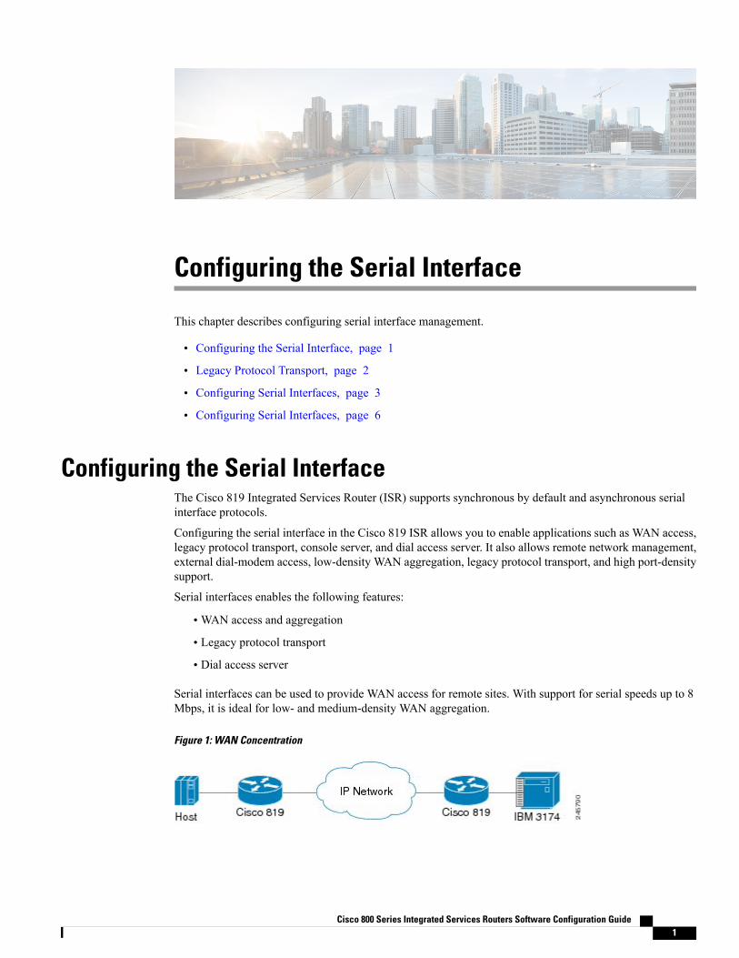
Legacy Protocol TransportSerial and synchronous/asynchronous ports are ideally suited to transport legacy traffic across a TCP/IPnetwork, facilitating network convergence. Legacy protocols supported by Cisco IOSR Software include:
• Synchronous Data Link Control (SDLC) Protocol
• Binary Synchronous Communications Protocol (Bisync)
• X.25 Protocol
Figure 2: Network Convergence
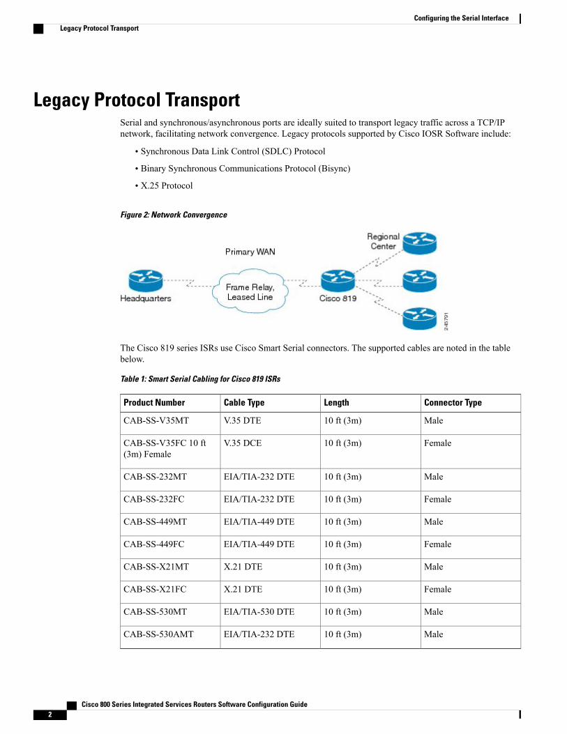
The Cisco 819 series ISRs use Cisco Smart Serial connectors. The supported cables are noted in the tablebelow.
Table 1: Smart Serial Cabling for Cisco 819 ISRs
Connector TypeLengthCable TypeProduct Number
Male10 ft (3m)V.35 DTECAB-SS-V35MT
Female10 ft (3m)V.35 DCECAB-SS-V35FC 10 ft(3m) Female
Male10 ft (3m)EIA/TIA-232 DTECAB-SS-232MT
Female10 ft (3m)EIA/TIA-232 DTECAB-SS-232FC
Male10 ft (3m)EIA/TIA-449 DTECAB-SS-449MT
Female10 ft (3m)EIA/TIA-449 DTECAB-SS-449FC
Male10 ft (3m)X.21 DTECAB-SS-X21MT
Female10 ft (3m)X.21 DTECAB-SS-X21FC
Male10 ft (3m)EIA/TIA-530 DTECAB-SS-530MT
Male10 ft (3m)EIA/TIA-232 DTECAB-SS-530AMT
Cisco 800 Series Integrated Services Routers Software Configuration Guide2
Configuring the Serial InterfaceLegacy Protocol Transport
Configuring Serial InterfacesWhen the router receives an indication that the primary interface is down, the backup interface becomesenabled. After the primary connection has been restored for a specified period, the backup interface is disabled.
Even if the backup interface comes out of standby mode, the router does not enable the backup interface unlessthe router receives the traffic specified for that backup interface.
To configure serial interfaces, you must understand the following concept:
Cisco HDLC EncapsulationCisco High-Level Data Link Controller (HDLC) is the Cisco proprietary protocol for sending data oversynchronous serial links using HDLC. Cisco HDLC also provides a simple control protocol called Serial LineAddress Resolution Protocol (SLARP) to maintain serial link keepalives. Cisco HDLC is the default for dataencapsulation at Layer 2 (data link) of the Open System Interconnection (OSI) stack for efficient packetdelineation and error control.
Cisco HDLC is the default encapsulation type for the serial interfaces.Note
When the encapsulation on a serial interface is changed from HDLC to any other encapsulation type, theconfigured serial subinterfaces on the main interface inherit the newly changed encapsulation and they do notget deleted.
Cisco HDLC uses keepalives to monitor the link state, as described in the Keepalive Timer, on page 5.
PPP EncapsulationPPP is a standard protocol used to send data over synchronous serial links. PPP also provides a Link ControlProtocol (LCP) for negotiating properties of the link. LCP uses echo requests and responses to monitor thecontinuing availability of the link.
When an interface is configured with PPP encapsulation, a link is declared down and full LCP negotiationis re-initiated after five echo request (ECHOREQ) packets are sent without receiving an echo response(ECHOREP).
Note
PPP provides the following Network Control Protocols (NCPs) for negotiating properties of data protocolsthat will run on the link:
• IP Control Protocol (IPCP) to negotiate IP properties
• Multiprotocol Label Switching control processor (MPLSCP) to negotiate MPLS properties
• Cisco Discovery Protocol control processor (CDPCP) to negotiate CDP properties
• IPv6CP to negotiate IP Version 6 (IPv6) properties
• Open Systems Interconnection control processor (OSICP) to negotiate OSI properties
Cisco 800 Series Integrated Services Routers Software Configuration Guide 3
Configuring the Serial InterfaceConfiguring Serial Interfaces
PPP uses keepalives to monitor the link state, as described in the Keepalive Timer, on page 5.
PPP supports the following authentication protocols, which require a remote device to prove its identity beforeallowing data traffic to flow over a connection:
• ChallengeHandshakeAuthentication Protocol (CHAP)—CHAP authentication sends a challengemessageto the remote device. The remote device encrypts the challenge value with a shared secret and returnsthe encrypted value and its name to the local router in a response message. The local router attempts tomatch the remote device’s name with an associated secret stored in the local username or remote securityserver database; it uses the stored secret to encrypt the original challenge and verify that the encryptedvalues match.
• Microsoft Challenge Handshake Authentication Protocol (MS-CHAP)—MS-CHAP is the Microsoftversion of CHAP. Like the standard version of CHAP, MS-CHAP is used for PPP authentication; inthis case, authentication occurs between a personal computer usingMicrosoftWindowsNT orMicrosoftWindows 95 and a Cisco router or access server acting as a network access server.
• Password Authentication Protocol (PAP)—PAP authentication requires the remote device to send aname and a password, which are checked against a matching entry in the local username database or inthe remote security server database.
Use the ppp authentication command in interface configuration mode to enable CHAP, MS-CHAP, andPAP on a serial interface.
Enabling or disabling PPP authentication does not effect the local router’s willingness to authenticate itselfto the remote device.
Note
Multilink PPPMultilink Point-to-Point Protocol (MLPPP) is supported on the Cisco 819 ISR serial interface.MLPPP providesa method for combining multiple physical links into one logical link. The implementation ofMLPPP combinesmultiple PPP serial interfaces into one multilink interface. MLPPP performs the fragmenting, reassembling,and sequencing of datagrams across multiple PPP links.
MLPPP provides the same features that are supported on PPP Serial interfaces with the exception of QoS. Italso provides the following additional features:
• Fragment sizes of 128, 256, and 512 bytes
• Long sequence numbers (24-bit)
• Lost fragment detection timeout period of 80 ms
• Minimum-active-links configuration option
• LCP echo request/reply support over multilink interface
• Full T1 and E1 framed and unframed links
Cisco 800 Series Integrated Services Routers Software Configuration Guide4
Configuring the Serial InterfacePPP Encapsulation
Keepalive TimerCisco keepalives are useful for monitoring the link state. Periodic keepalives are sent to and received fromthe peer at a frequency determined by the value of the keepalive timer. If an acceptable keepalive response isnot received from the peer, the link makes the transition to the down state. As soon as an acceptable keepaliveresponse is obtained from the peer or if keepalives are disabled, the link makes the transition to the up state.
The keepalive command applies to serial interfaces using HDLC or PPP encapsulation. It does not applyto serial interfaces using Frame Relay encapsulation.
Note
For each encapsulation type, a certain number of keepalives ignored by a peer triggers the serial interface totransition to the down state. For HDLC encapsulation, three ignored keepalives causes the interface to bebrought down. For PPP encapsulation, five ignored keepalives causes the interface to be brought down.ECHOREQ packets are sent out only when LCP negotiation is complete (for example, when LCP is open).
Use the keepalive command in interface configuration mode to set the frequency at which LCP sendsECHOREQ packets to its peer. To restore the system to the default keepalive interval of 10 seconds, use thekeepalive command with the no keyword. To disable keepalives, use the keepalive disable command. Forboth PPP and Cisco HDLC, a keepalive of 0 disables keepalives and is reported in the show running-configcommand output as keepalive disable.
When LCP is running on the peer and receives an ECHOREQ packet, it responds with an ECHOREP packet,regardless of whether keepalives are enabled on the peer.
Keepalives are independent between the two peers. One peer end can have keepalives enabled; the other endcan have them disabled. Even if keepalives are disabled locally, LCP still responds with ECHOREP packetsto the ECHOREQ packets it receives. Similarly, LCP also works if the period of keepalives at each end isdifferent.
Frame Relay EncapsulationWhen Frame Relay encapsulation is enabled on a serial interface, the interface configuration is hierarchicaland comprises the following elements:
• The serial main interface comprises the physical interface and port. If you are not using the serial interfaceto support Cisco HDLC and PPP encapsulated connections, then you must configure subinterfaces withpermanent virtual circuits (PVCs) under the serial main interface. Frame Relay connections are supportedon PVCs only.
• Serial subinterfaces are configured under the serial main interface. A serial subinterface does not activelycarry traffic until you configure a PVC under the serial subinterface. Layer 3 configuration typicallytakes place on the subinterface.
•When the encapsulation on a serial interface is changed from HDLC to any other encapsulation type,the configured serial subinterfaces on the main interface inherit the newly changed encapsulation andthey do not get deleted.
• Point-to-point PVCs are configured under a serial subinterface. You cannot configure a PVC directlyunder a main interface. A single point-to-point PVC is allowed per subinterface. PVCs use a predefinedcircuit path and fail if the path is interrupted. PVCs remain active until the circuit is removed from eitherconfiguration. Connections on the serial PVC support Frame Relay encapsulation only.
Cisco 800 Series Integrated Services Routers Software Configuration Guide 5
Configuring the Serial InterfaceKeepalive Timer
The administrative state of a parent interface drives the state of the subinterface and its PVC. When theadministrative state of a parent interface or subinterface changes, so does the administrative state of anychild PVC configured under that parent interface or subinterface.
Note
To configure FrameRelay encapsulation on serial interfaces, use the encapsulation (FrameRelayVC-bundle)command.
Frame Relay interfaces support two types of encapsulated frames:
• Cisco (default)
• IETF
Use the encap command in PVC configuration mode to configure Cisco or IETF encapsulation on a PVC. Ifthe encapsulation type is not configured explicitly for a PVC, then that PVC inherits the encapsulation typefrom the main serial interface.
Cisco encapsulation is required on serial main interfaces that are configured forMPLS. IETF encapsulationis not supported for MPLS.
Note
Before you configure Frame Relay encapsulation on an interface, you must verify that all prior Layer 3configuration is removed from that interface. For example, you must ensure that there is no IP addressconfigured directly under the main interface; otherwise, any Frame Relay configuration done under the maininterface will not be viable.
LMI on Frame Relay InterfacesThe Local Management Interface (LMI) protocol monitors the addition, deletion, and status of PVCs. LMIalso verifies the integrity of the link that forms a Frame Relay UNI interface. By default, cisco LMI is enabledon all PVCs.
If the LMI type is cisco (the default LMI type), the maximum number of PVCs that can be supported undera single interface is related to the MTU size of the main interface. Use the following formula to calculate themaximum number of PVCs supported on a card or SPA:
(MTU - 13)/8 = maximum number of PVCs
The default setting of themtu command for a serial interface is 1504 bytes. Therefore, the default numbersof PVCs supported on a serial interface configured with cisco LMI is 186.
Note
Configuring Serial InterfacesThis section contains the following tasks:
Cisco 800 Series Integrated Services Routers Software Configuration Guide6
Configuring the Serial InterfaceConfiguring Serial Interfaces
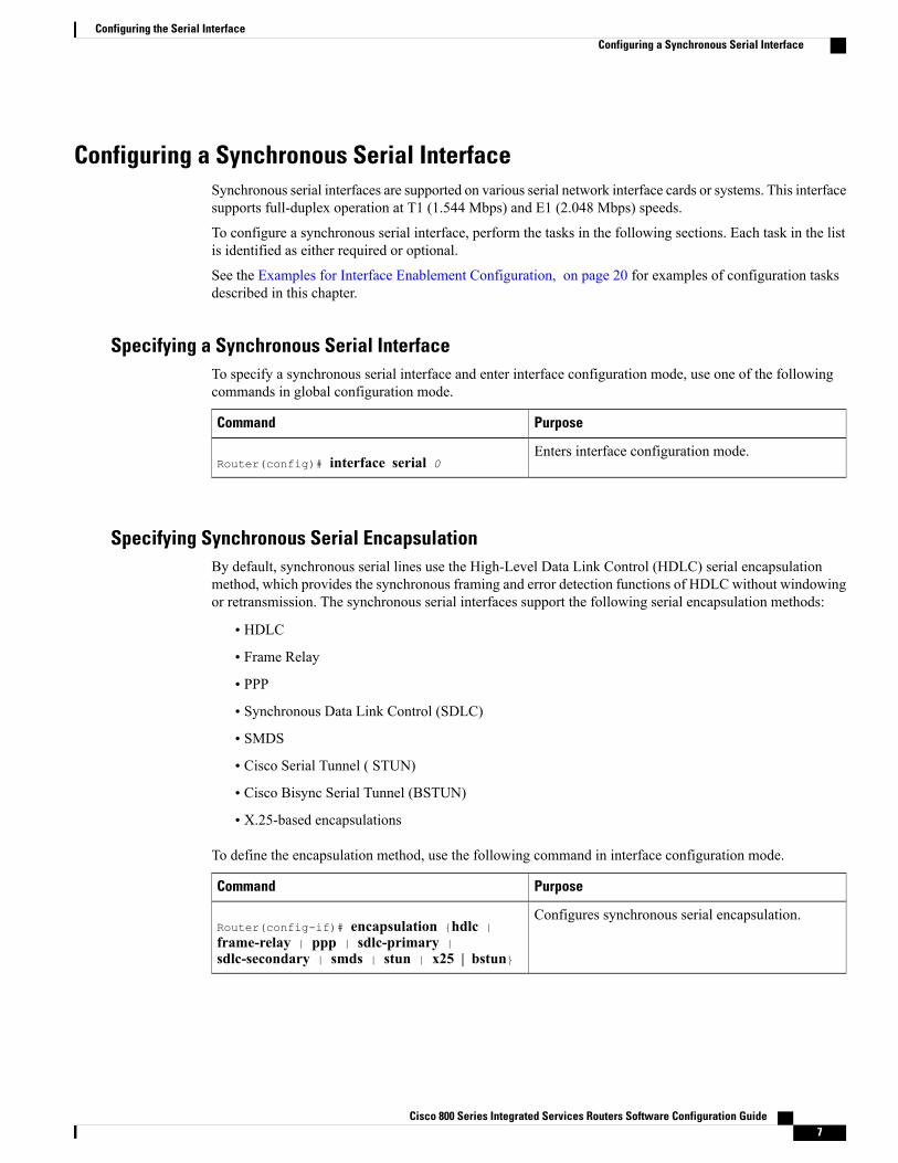
Configuring a Synchronous Serial InterfaceSynchronous serial interfaces are supported on various serial network interface cards or systems. This interfacesupports full-duplex operation at T1 (1.544 Mbps) and E1 (2.048 Mbps) speeds.
To configure a synchronous serial interface, perform the tasks in the following sections. Each task in the listis identified as either required or optional.
See the Examples for Interface Enablement Configuration, on page 20 for examples of configuration tasksdescribed in this chapter.
Specifying a Synchronous Serial InterfaceTo specify a synchronous serial interface and enter interface configuration mode, use one of the followingcommands in global configuration mode.
PurposeCommand
Enters interface configuration mode.Router(config)# interface serial 0
Specifying Synchronous Serial EncapsulationBy default, synchronous serial lines use the High-Level Data Link Control (HDLC) serial encapsulationmethod, which provides the synchronous framing and error detection functions of HDLC without windowingor retransmission. The synchronous serial interfaces support the following serial encapsulation methods:
• HDLC
• Frame Relay
• PPP
• Synchronous Data Link Control (SDLC)
• SMDS
• Cisco Serial Tunnel ( STUN)
• Cisco Bisync Serial Tunnel (BSTUN)
• X.25-based encapsulations
To define the encapsulation method, use the following command in interface configuration mode.
PurposeCommand
Configures synchronous serial encapsulation.Router(config-if)# encapsulation {hdlc |frame-relay | ppp | sdlc-primary |sdlc-secondary | smds | stun | x25 | bstun}
Cisco 800 Series Integrated Services Routers Software Configuration Guide 7
Configuring the Serial InterfaceConfiguring a Synchronous Serial Interface
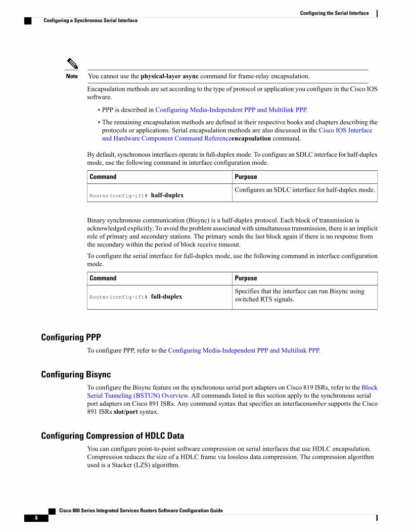
You cannot use the physical-layer async command for frame-relay encapsulation.Note
Encapsulation methods are set according to the type of protocol or application you configure in the Cisco IOSsoftware.
• PPP is described in Configuring Media-Independent PPP and Multilink PPP.
• The remaining encapsulation methods are defined in their respective books and chapters describing theprotocols or applications. Serial encapsulation methods are also discussed in the Cisco IOS Interfaceand Hardware Component Command Referenceencapsulation command.
By default, synchronous interfaces operate in full-duplexmode. To configure an SDLC interface for half-duplexmode, use the following command in interface configuration mode.
PurposeCommand
Configures an SDLC interface for half-duplex mode.Router(config-if)# half-duplex
Binary synchronous communication (Bisync) is a half-duplex protocol. Each block of transmission isacknowledged explicitly. To avoid the problem associated with simultaneous transmission, there is an implicitrole of primary and secondary stations. The primary sends the last block again if there is no response fromthe secondary within the period of block receive timeout.
To configure the serial interface for full-duplex mode, use the following command in interface configurationmode.
PurposeCommand
Specifies that the interface can run Bisync usingswitched RTS signals.Router(config-if)# full-duplex
Configuring PPPTo configure PPP, refer to the Configuring Media-Independent PPP and Multilink PPP.
Configuring BisyncTo configure the Bisync feature on the synchronous serial port adapters on Cisco 819 ISRs, refer to the BlockSerial Tunneling (BSTUN) Overview. All commands listed in this section apply to the synchronous serialport adapters on Cisco 891 ISRs. Any command syntax that specifies an interfacenumber supports the Cisco891 ISRs slot/port syntax.
Configuring Compression of HDLC DataYou can configure point-to-point software compression on serial interfaces that use HDLC encapsulation.Compression reduces the size of a HDLC frame via lossless data compression. The compression algorithmused is a Stacker (LZS) algorithm.
Cisco 800 Series Integrated Services Routers Software Configuration Guide8
Configuring the Serial InterfaceConfiguring a Synchronous Serial Interface
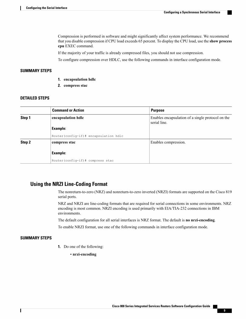
Compression is performed in software and might significantly affect system performance. We recommendthat you disable compression if CPU load exceeds 65 percent. To display the CPU load, use the show processcpu EXEC command.
If the majority of your traffic is already compressed files, you should not use compression.
To configure compression over HDLC, use the following commands in interface configuration mode.
SUMMARY STEPS
1. encapsulation hdlc2. compress stac
DETAILED STEPS
PurposeCommand or Action
Enables encapsulation of a single protocol on theserial line.
encapsulation hdlc
Example:
Router(config-if)# encapsulation hdlc
Step 1
Enables compression.compress stac
Example:
Router(config-if)# compress stac
Step 2
Using the NRZI Line-Coding FormatThe nonreturn-to-zero (NRZ) and nonreturn-to-zero inverted (NRZI) formats are supported on the Cisco 819serial ports.
NRZ and NRZI are line-coding formats that are required for serial connections in some environments. NRZencoding is most common. NRZI encoding is used primarily with EIA/TIA-232 connections in IBMenvironments.
The default configuration for all serial interfaces is NRZ format. The default is no nrzi-encoding.
To enable NRZI format, use one of the following commands in interface configuration mode.
SUMMARY STEPS
1. Do one of the following:
• nrzi-encoding
Cisco 800 Series Integrated Services Routers Software Configuration Guide 9
Configuring the Serial InterfaceConfiguring a Synchronous Serial Interface
DETAILED STEPS
PurposeCommand or Action
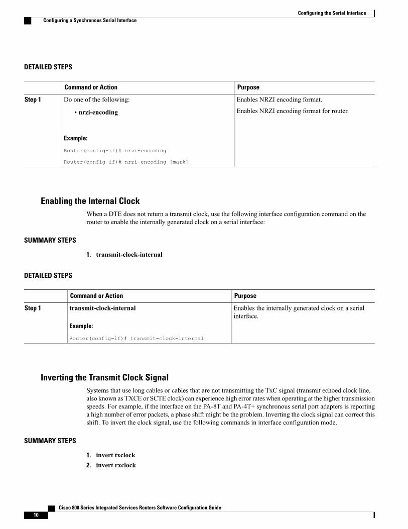
Enables NRZI encoding format.Do one of the following:Step 1
Enables NRZI encoding format for router.• nrzi-encoding
Example:
Router(config-if)# nrzi-encoding
Router(config-if)# nrzi-encoding [mark]
Enabling the Internal ClockWhen a DTE does not return a transmit clock, use the following interface configuration command on therouter to enable the internally generated clock on a serial interface:
SUMMARY STEPS
1. transmit-clock-internal
DETAILED STEPS
PurposeCommand or Action
Enables the internally generated clock on a serialinterface.
transmit-clock-internal
Example:
Router(config-if)# transmit-clock-internal
Step 1
Inverting the Transmit Clock SignalSystems that use long cables or cables that are not transmitting the TxC signal (transmit echoed clock line,also known as TXCE or SCTE clock) can experience high error rates when operating at the higher transmissionspeeds. For example, if the interface on the PA-8T and PA-4T+ synchronous serial port adapters is reportinga high number of error packets, a phase shift might be the problem. Inverting the clock signal can correct thisshift. To invert the clock signal, use the following commands in interface configuration mode.
SUMMARY STEPS
1. invert txclock2. invert rxclock
Cisco 800 Series Integrated Services Routers Software Configuration Guide10
Configuring the Serial InterfaceConfiguring a Synchronous Serial Interface
DETAILED STEPS
PurposeCommand or Action
Inverts the clock signal on an interface.invert txclock
Example:
Router(config-if)# invert txclock
Step 1
Inverts the phase of the RX clock on the UIO serial interface,which does not use the T1/E1 interface.
invert rxclock
Example:
Router(config-if)# invert rxclock
Step 2
Setting Transmit DelayIt is possible to send back-to-back data packets over serial interfaces faster than some hosts can receive them.You can specify a minimum dead time after transmitting a packet to remove this condition. This setting isavailable for serial interfaces on the MCI and SCI interface cards and for the HSSI or MIP. Use one of thefollowing commands, as appropriate for your system, in interface configuration mode.
PurposeCommand
Sets the transmit delay on the MCI and SCIsynchronous serial interfaces.Router(config-if)# transmitter-delay
microseconds
Sets the transmit delay on the HSSI or MIP.Router(config-if)# transmitter-delay hdlc-flags
Configuring DTR Signal PulsingYou can configure pulsing Data Terminal Ready (DTR) signals on all serial interfaces. When the serial lineprotocol goes down (for example, because of loss of synchronization), the interface hardware is reset and theDTR signal is held inactive for at least the specified interval. This function is useful for handling encryptingor other similar devices that use the toggling of the DTR signal to reset synchronization. To configure DTRsignal pulsing, use the following command in interface configuration mode.
PurposeCommand
Configures DTR signal pulsing.Router(config-if)# pulse-time seconds
Cisco 800 Series Integrated Services Routers Software Configuration Guide 11
Configuring the Serial InterfaceConfiguring a Synchronous Serial Interface
Ignoring DCD and Monitoring DSR as Line Up/Down IndicatorBy default, when the serial interface is operating in DTE mode, it monitors the Data Carrier Detect (DCD)signal as the line up/down indicator. By default, the attached DCE device sends the DCD signal. When theDTE interface detects the DCD signal, it changes the state of the interface to up.
In some configurations, such as an SDLC multidrop environment, the DCE device sends the Data Set Ready(DSR) signal instead of the DCD signal, which prevents the interface from coming up. To tell the interfaceto monitor the DSR signal instead of the DCD signal as the line up/down indicator, use the following commandin interface configuration mode.
SUMMARY STEPS
1. ignore-dcd
DETAILED STEPS
PurposeCommand or Action
Configures the serial interface to monitor the DSR signal as theline up/down indicator.
ignore-dcd
Example:
Router(config-if)# ignore-dcd
Step 1
What to Do Next
Unless you know for certain that you really need this feature, be very careful using this command. It willhide the real status of the interface. The interface could actually be down and you will not know just bylooking at show displays.
Caution
Specifying the Serial Network Interface Module TimingOn Cisco 819 series ISRs, you can specify the serial Network Interface Module timing signal configuration.When the board is operating as a DCE and the DTE provides terminal timing (SCTE or TT), you can configurethe DCE to use SCTE from the DTE. When running the line at high speeds and long distances, this strategyprevents phase shifting of the data with respect to the clock.
To configure the DCE to use SCTE from the DTE, use the following command in interface configurationmode.
SUMMARY STEPS
1. dce-terminal-timing enable
Cisco 800 Series Integrated Services Routers Software Configuration Guide12
Configuring the Serial InterfaceConfiguring a Synchronous Serial Interface
DETAILED STEPS
PurposeCommand or Action
Configures the DCE to use SCTE from the DTE.dce-terminal-timing enable
Example:
Router(config-if)# dce-terminal-timing enable
Step 1
Specifying the Serial Network Interface Module TimingWhen the board is operating as a DTE, you can invert the TXC clock signal it gets from the DCE that theDTE uses to transmit data. Invert the clock signal if the DCE cannot receive SCTE from the DTE, the data isrunning at high speeds, and the transmission line is long. Again, this prevents phase shifting of the data withrespect to the clock.
To configure the interface so that the router inverts the TXC clock signal, use the following command ininterface configuration mode.
SUMMARY STEPS
1. dte-invert-txc
DETAILED STEPS
PurposeCommand or Action
Specifies timing configuration to invert TXC clocksignal.
dte-invert-txc
Example:
Router(config-if)# dte-invert-txc
Step 1
Configuring Low-Speed Serial InterfacesThis section describes how to configure low-speed serial interfaces and contains the following sections:
For configuration examples, see the Examples for Low-Speed Serial Interface, on page 20.
Half-Duplex DTE and DCE State MachinesThe following sections describe the communication between half-duplex DTE transmit and receive statemachines and half-duplex DCE transmit and receive state machines.
Cisco 800 Series Integrated Services Routers Software Configuration Guide 13
Configuring the Serial InterfaceConfiguring Low-Speed Serial Interfaces
Half-Duplex DTE State Machines
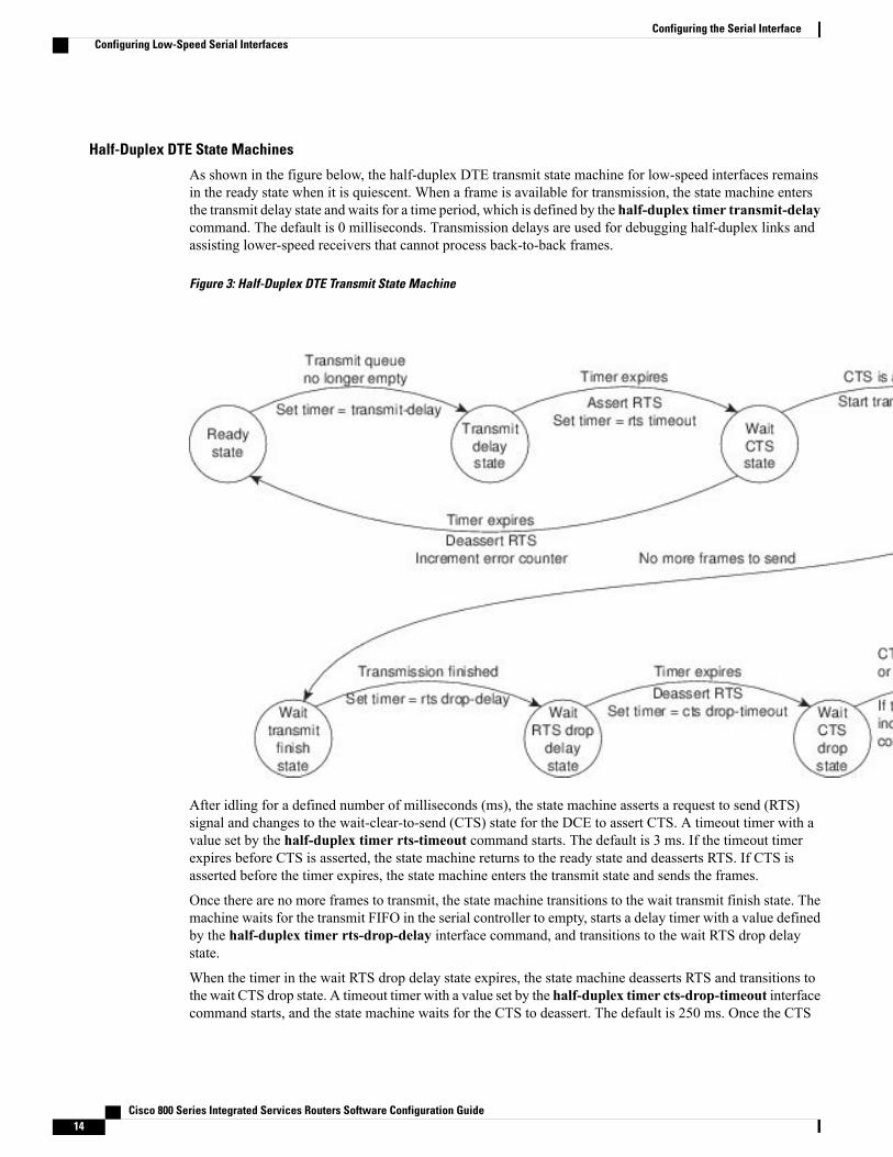
As shown in the figure below, the half-duplex DTE transmit state machine for low-speed interfaces remainsin the ready state when it is quiescent. When a frame is available for transmission, the state machine entersthe transmit delay state and waits for a time period, which is defined by the half-duplex timer transmit-delaycommand. The default is 0 milliseconds. Transmission delays are used for debugging half-duplex links andassisting lower-speed receivers that cannot process back-to-back frames.
Figure 3: Half-Duplex DTE Transmit State Machine
After idling for a defined number of milliseconds (ms), the state machine asserts a request to send (RTS)signal and changes to the wait-clear-to-send (CTS) state for the DCE to assert CTS. A timeout timer with avalue set by the half-duplex timer rts-timeout command starts. The default is 3 ms. If the timeout timerexpires before CTS is asserted, the state machine returns to the ready state and deasserts RTS. If CTS isasserted before the timer expires, the state machine enters the transmit state and sends the frames.
Once there are no more frames to transmit, the state machine transitions to the wait transmit finish state. Themachine waits for the transmit FIFO in the serial controller to empty, starts a delay timer with a value definedby the half-duplex timer rts-drop-delay interface command, and transitions to the wait RTS drop delaystate.
When the timer in the wait RTS drop delay state expires, the state machine deasserts RTS and transitions tothe wait CTS drop state. A timeout timer with a value set by the half-duplex timer cts-drop-timeout interfacecommand starts, and the state machine waits for the CTS to deassert. The default is 250 ms. Once the CTS
Cisco 800 Series Integrated Services Routers Software Configuration Guide14
Configuring the Serial InterfaceConfiguring Low-Speed Serial Interfaces
signal is deasserted or the timeout timer expires, the state machine transitions back to the ready state. If thetimer expires before CTS is deasserted, an error counter is incremented, which can be displayed by issuingthe show controllers command for the serial interface in question.
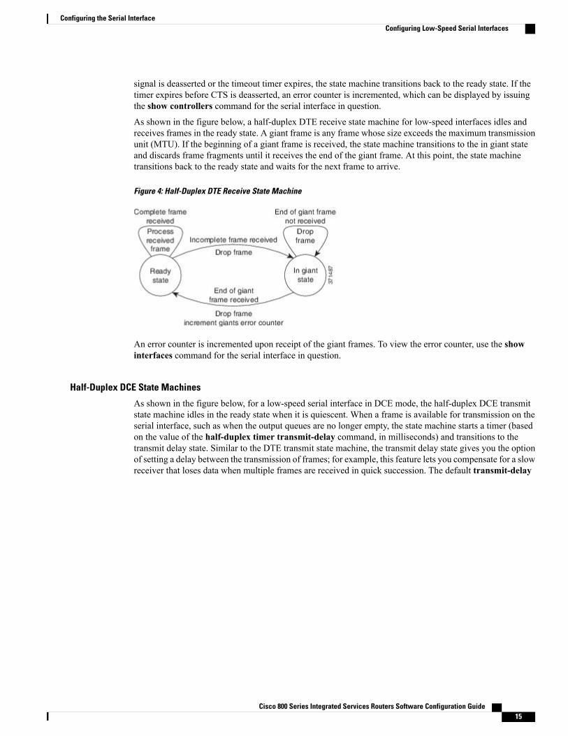
As shown in the figure below, a half-duplex DTE receive state machine for low-speed interfaces idles andreceives frames in the ready state. A giant frame is any frame whose size exceeds the maximum transmissionunit (MTU). If the beginning of a giant frame is received, the state machine transitions to the in giant stateand discards frame fragments until it receives the end of the giant frame. At this point, the state machinetransitions back to the ready state and waits for the next frame to arrive.
Figure 4: Half-Duplex DTE Receive State Machine
An error counter is incremented upon receipt of the giant frames. To view the error counter, use the showinterfaces command for the serial interface in question.
Half-Duplex DCE State Machines
As shown in the figure below, for a low-speed serial interface in DCE mode, the half-duplex DCE transmitstate machine idles in the ready state when it is quiescent. When a frame is available for transmission on theserial interface, such as when the output queues are no longer empty, the state machine starts a timer (basedon the value of the half-duplex timer transmit-delay command, in milliseconds) and transitions to thetransmit delay state. Similar to the DTE transmit state machine, the transmit delay state gives you the optionof setting a delay between the transmission of frames; for example, this feature lets you compensate for a slowreceiver that loses data when multiple frames are received in quick succession. The default transmit-delay
Cisco 800 Series Integrated Services Routers Software Configuration Guide 15
Configuring the Serial InterfaceConfiguring Low-Speed Serial Interfaces
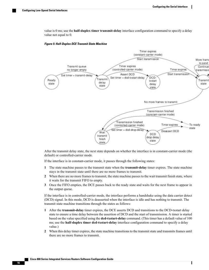
value is 0 ms; use the half-duplex timer transmit-delay interface configuration command to specify a delayvalue not equal to 0.
Figure 5: Half-Duplex DCE Transmit State Machine
After the transmit delay state, the next state depends on whether the interface is in constant-carrier mode (thedefault) or controlled-carrier mode.
If the interface is in constant-carrier mode, it passes through the following states:
1 The state machine passes to the transmit state when the transmit-delay timer expires. The state machinestays in the transmit state until there are no more frames to transmit.
2 When there are nomore frames to transmit, the state machine passes to the wait transmit finish state, whereit waits for the transmit FIFO to empty.
3 Once the FIFO empties, the DCE passes back to the ready state and waits for the next frame to appear inthe output queue.
If the interface is in controlled-carrier mode, the interface performs a handshake using the data carrier detect(DCD) signal. In this mode, DCD is deasserted when the interface is idle and has nothing to transmit. Thetransmit state machine transitions through the states as follows:
1 After the transmit-delay timer expires, the DCE asserts DCD and transitions to the DCD-txstart delaystate to ensure a time delay between the assertion of DCD and the start of transmission. A timer is startedbased on the value specified using the dcd-txstart-delay command. (This timer has a default value of 100ms; use the half-duplex timer dcd-txstart-delay interface configuration command to specify a delayvalue.)
2 When this delay timer expires, the state machine transitions to the transmit state and transmits frames untilthere are no more frames to transmit.
Cisco 800 Series Integrated Services Routers Software Configuration Guide16
Configuring the Serial InterfaceConfiguring Low-Speed Serial Interfaces
3 After the DCE transmits the last frame, it transitions to the wait transmit finish state, where it waits fortransmit FIFO to empty and the last frame to transmit to the wire. Then DCE starts a delay timer byspecifying the value using the dcd-drop-delay command. (This timer has the default value of 100 ms;use the half-duplex timer dcd-drop-delay interface configuration command to specify a delay value.)
4 The DCE transitions to the wait DCD drop delay state. This state causes a time delay between thetransmission of the last frame and the deassertion of DCD in the controlled-carrier mode for DCE transmits.
5 When the timer expires, the DCE deasserts DCD and transitions back to the ready state and stays thereuntil there is a frame to transmit on that interface.
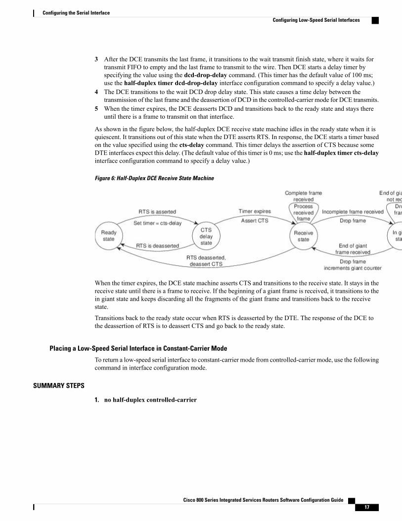
As shown in the figure below, the half-duplex DCE receive state machine idles in the ready state when it isquiescent. It transitions out of this state when the DTE asserts RTS. In response, the DCE starts a timer basedon the value specified using the cts-delay command. This timer delays the assertion of CTS because someDTE interfaces expect this delay. (The default value of this timer is 0 ms; use the half-duplex timer cts-delayinterface configuration command to specify a delay value.)
Figure 6: Half-Duplex DCE Receive State Machine
When the timer expires, the DCE state machine asserts CTS and transitions to the receive state. It stays in thereceive state until there is a frame to receive. If the beginning of a giant frame is received, it transitions to thein giant state and keeps discarding all the fragments of the giant frame and transitions back to the receivestate.
Transitions back to the ready state occur when RTS is deasserted by the DTE. The response of the DCE tothe deassertion of RTS is to deassert CTS and go back to the ready state.
Placing a Low-Speed Serial Interface in Constant-Carrier Mode
To return a low-speed serial interface to constant-carrier mode from controlled-carrier mode, use the followingcommand in interface configuration mode.
SUMMARY STEPS
1. no half-duplex controlled-carrier
Cisco 800 Series Integrated Services Routers Software Configuration Guide 17
Configuring the Serial InterfaceConfiguring Low-Speed Serial Interfaces
DETAILED STEPS
PurposeCommand or Action
Places a low-speed serial interface inconstant-carrier mode.
no half-duplex controlled-carrier
Example:
Router(config-if)# no half-duplex controlled-carrier
Step 1
Tuning Half-Duplex Timers
To optimize the performance of half-duplex timers, use the following command in interface configurationmode.
PurposeCommand
Tunes half-duplex timers.Router(config-if)# half-duplex timer {cts-delayvalue | cts-drop-timeout value|dcd-drop-delay value | dcd-txstart-delay value
|rts-drop-delay value| rts-timeout value |transmit-delay value}
The timer tuning commands permit you to adjust the timing of the half-duplex state machines to suit theparticular needs of their half-duplex installation.
Note that the half-duplex timer command and its options replaces the following two timer tuning commandsthat are available only on high-speed serial interfaces:
• sdlc cts-delay
• sdlc rts-timeout
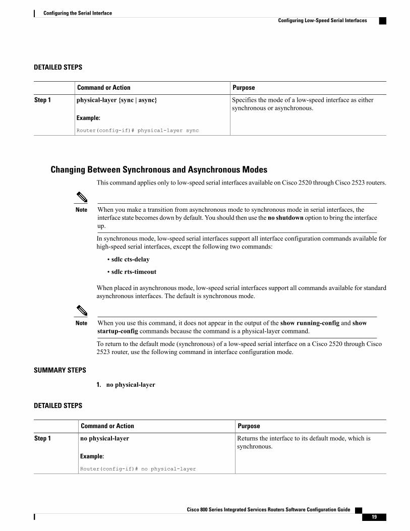
Changing Between Synchronous and Asynchronous ModesTo specify the mode of a low-speed serial interface as either synchronous or asynchronous, use the followingcommand in interface configuration mode.
SUMMARY STEPS
1. physical-layer {sync | async}
Cisco 800 Series Integrated Services Routers Software Configuration Guide18
Configuring the Serial InterfaceConfiguring Low-Speed Serial Interfaces
DETAILED STEPS
PurposeCommand or Action
Specifies the mode of a low-speed interface as eithersynchronous or asynchronous.
physical-layer {sync | async}
Example:
Router(config-if)# physical-layer sync
Step 1
Changing Between Synchronous and Asynchronous ModesThis command applies only to low-speed serial interfaces available on Cisco 2520 through Cisco 2523 routers.
When you make a transition from asynchronous mode to synchronous mode in serial interfaces, theinterface state becomes down by default. You should then use the no shutdown option to bring the interfaceup.
Note
In synchronous mode, low-speed serial interfaces support all interface configuration commands available forhigh-speed serial interfaces, except the following two commands:
• sdlc cts-delay
• sdlc rts-timeout
When placed in asynchronous mode, low-speed serial interfaces support all commands available for standardasynchronous interfaces. The default is synchronous mode.
When you use this command, it does not appear in the output of the show running-config and showstartup-config commands because the command is a physical-layer command.
Note
To return to the default mode (synchronous) of a low-speed serial interface on a Cisco 2520 through Cisco2523 router, use the following command in interface configuration mode.
SUMMARY STEPS
1. no physical-layer
DETAILED STEPS
PurposeCommand or Action
Returns the interface to its default mode, which issynchronous.
no physical-layer
Example:
Router(config-if)# no physical-layer
Step 1
Cisco 800 Series Integrated Services Routers Software Configuration Guide 19
Configuring the Serial InterfaceConfiguring Low-Speed Serial Interfaces
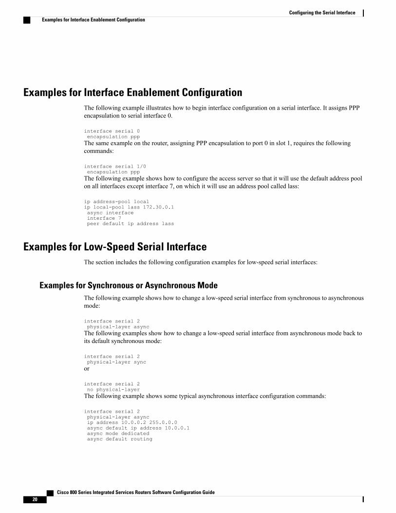
Examples for Interface Enablement ConfigurationThe following example illustrates how to begin interface configuration on a serial interface. It assigns PPPencapsulation to serial interface 0.
interface serial 0encapsulation pppThe same example on the router, assigning PPP encapsulation to port 0 in slot 1, requires the followingcommands:
interface serial 1/0encapsulation pppThe following example shows how to configure the access server so that it will use the default address poolon all interfaces except interface 7, on which it will use an address pool called lass:
ip address-pool localip local-pool lass 172.30.0.1async interfaceinterface 7peer default ip address lass
Examples for Low-Speed Serial InterfaceThe section includes the following configuration examples for low-speed serial interfaces:
Examples for Synchronous or Asynchronous ModeThe following example shows how to change a low-speed serial interface from synchronous to asynchronousmode:
interface serial 2physical-layer asyncThe following examples show how to change a low-speed serial interface from asynchronous mode back toits default synchronous mode:
interface serial 2physical-layer syncor
interface serial 2no physical-layerThe following example shows some typical asynchronous interface configuration commands:
interface serial 2physical-layer asyncip address 10.0.0.2 255.0.0.0async default ip address 10.0.0.1async mode dedicatedasync default routing
Cisco 800 Series Integrated Services Routers Software Configuration Guide20
Configuring the Serial InterfaceExamples for Interface Enablement Configuration
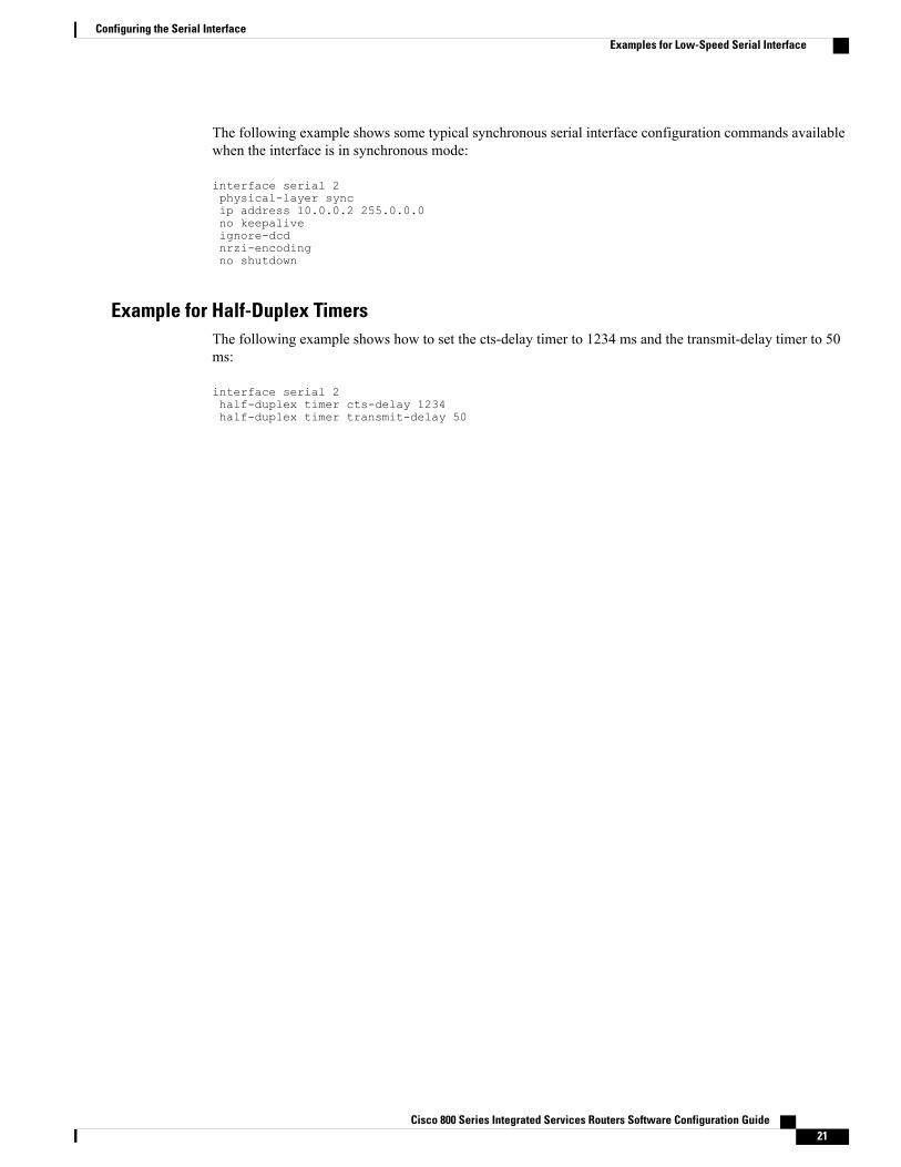
The following example shows some typical synchronous serial interface configuration commands availablewhen the interface is in synchronous mode:
interface serial 2physical-layer syncip address 10.0.0.2 255.0.0.0no keepaliveignore-dcdnrzi-encodingno shutdown
Example for Half-Duplex TimersThe following example shows how to set the cts-delay timer to 1234 ms and the transmit-delay timer to 50ms:
interface serial 2half-duplex timer cts-delay 1234half-duplex timer transmit-delay 50
Cisco 800 Series Integrated Services Routers Software Configuration Guide 21
Configuring the Serial InterfaceExamples for Low-Speed Serial Interface

Cisco 800 Series Integrated Services Routers Software Configuration Guide22
Configuring the Serial InterfaceExamples for Low-Speed Serial Interface