Embed Size (px)
Citation preview
Cisco
C H A P T E R 62
Configuring the ASA IPS ModuleThis chapter describes how to configure the ASA IPS module. The ASA IPS module might be a physical module or a software module, depending on your ASA model. For a list of supported ASA IPS modules per ASA model, see the Cisco ASA Compatibility Matrix:
http://www.cisco.com/en/US/docs/security/asa/compatibility/asamatrx.html
This chapter includes the following sections:
• Information About the ASA IPS module, page 62-1
• Licensing Requirements for the ASA IPS module, page 62-5
• Guidelines and Limitations, page 62-5
• Default Settings, page 62-6
• Configuring the ASA IPS module, page 62-6
• Monitoring the ASA IPS module, page 62-20
• Troubleshooting the ASA IPS module, page 62-21
• Configuration Examples for the ASA IPS module, page 62-25
• Feature History for the ASA IPS module, page 62-25
Information About the ASA IPS moduleThe ASA IPS module runs advanced IPS software that provides proactive, full-featured intrusion prevention services to stop malicious traffic, including worms and network viruses, before they can affect your network. This section includes the following topics:
• How the ASA IPS module Works with the ASA, page 62-2
• Operating Modes, page 62-2
• Using Virtual Sensors (ASA 5510 and Higher), page 62-3
• Information About Management Access, page 62-4
62-1 ASA 5500 Series Configuration Guide using the CLI
Chapter 62 Configuring the ASA IPS Module Information About the ASA IPS module
How the ASA IPS module Works with the ASAThe ASA IPS module runs a separate application from the ASA. The ASA IPS module might include an external management interface so you can connect to the ASA IPS module directly; if it does not have a management interface, you can connect to the ASA IPS module through the ASA interface. Any other interfaces on the ASA IPS module, if available for your model, are used for ASA traffic only.
Traffic goes through the firewall checks before being forwarded to the ASA IPS module. When you identify traffic for IPS inspection on the ASA, traffic flows through the ASA and the ASA IPS module as follows. Note: This example is for “inline mode.” See the “Operating Modes” section on page 62-2 for information about “promiscuous mode,” where the ASA only sends a copy of the traffic to the ASA IPS module.
1. Traffic enters the ASA.
2. Incoming VPN traffic is decrypted.
3. Firewall policies are applied.
4. Traffic is sent to the ASA IPS module.
5. The ASA IPS module applies its security policy to the traffic, and takes appropriate actions.
6. Valid traffic is sent back to the ASA; the ASA IPS module might block some traffic according to its security policy, and that traffic is not passed on.
7. Outgoing VPN traffic is encrypted.
8. Traffic exits the ASA.
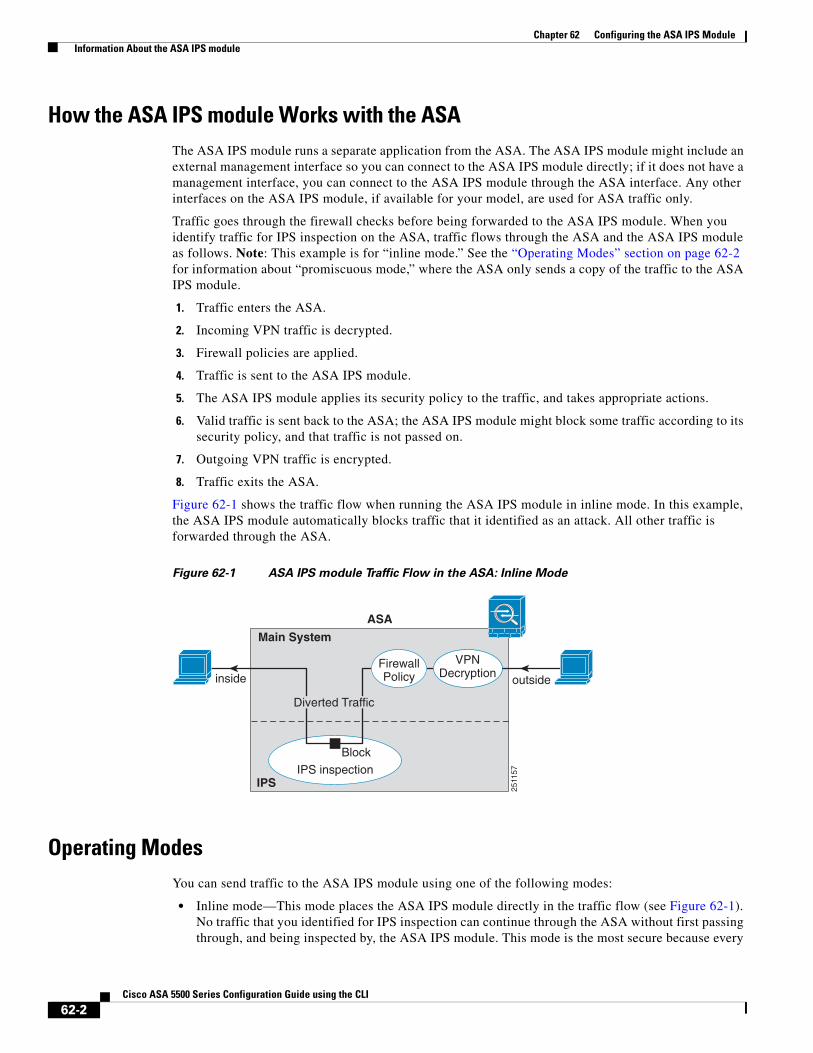
Figure 62-1 shows the traffic flow when running the ASA IPS module in inline mode. In this example, the ASA IPS module automatically blocks traffic that it identified as an attack. All other traffic is forwarded through the ASA.
Figure 62-1 ASA IPS module Traffic Flow in the ASA: Inline Mode
Operating ModesYou can send traffic to the ASA IPS module using one of the following modes:
• Inline mode—This mode places the ASA IPS module directly in the traffic flow (see Figure 62-1). No traffic that you identified for IPS inspection can continue through the ASA without first passing through, and being inspected by, the ASA IPS module. This mode is the most secure because every
ASA
Main System
IPS
Diverted Traffic
IPS inspection
VPNDecryption
FirewallPolicy
Block
2511
57
inside outside
62-2Cisco ASA 5500 Series Configuration Guide using the CLI
Chapter 62 Configuring the ASA IPS Module Information About the ASA IPS module
packet that you identify for inspection is analyzed before being allowed through. Also, the ASA IPS module can implement a blocking policy on a packet-by-packet basis. This mode, however, can affect throughput.
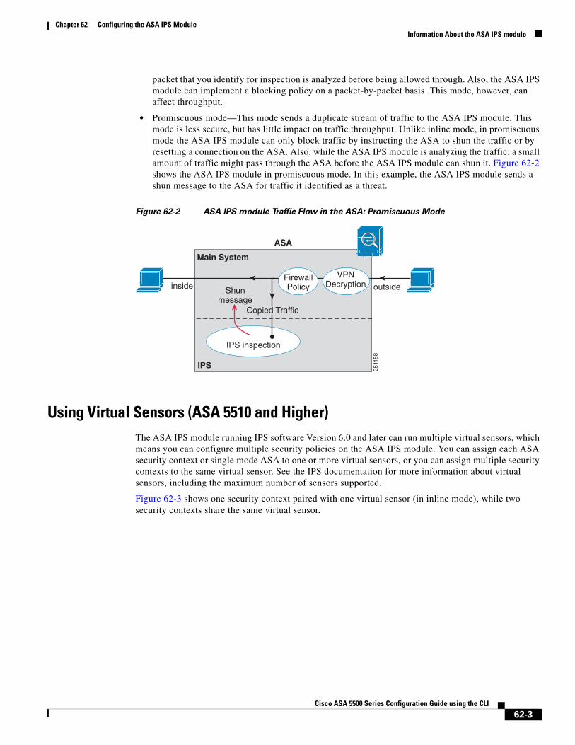
• Promiscuous mode—This mode sends a duplicate stream of traffic to the ASA IPS module. This mode is less secure, but has little impact on traffic throughput. Unlike inline mode, in promiscuous mode the ASA IPS module can only block traffic by instructing the ASA to shun the traffic or by resetting a connection on the ASA. Also, while the ASA IPS module is analyzing the traffic, a small amount of traffic might pass through the ASA before the ASA IPS module can shun it. Figure 62-2 shows the ASA IPS module in promiscuous mode. In this example, the ASA IPS module sends a shun message to the ASA for traffic it identified as a threat.
Figure 62-2 ASA IPS module Traffic Flow in the ASA: Promiscuous Mode
Using Virtual Sensors (ASA 5510 and Higher)The ASA IPS module running IPS software Version 6.0 and later can run multiple virtual sensors, which means you can configure multiple security policies on the ASA IPS module. You can assign each ASA security context or single mode ASA to one or more virtual sensors, or you can assign multiple security contexts to the same virtual sensor. See the IPS documentation for more information about virtual sensors, including the maximum number of sensors supported.
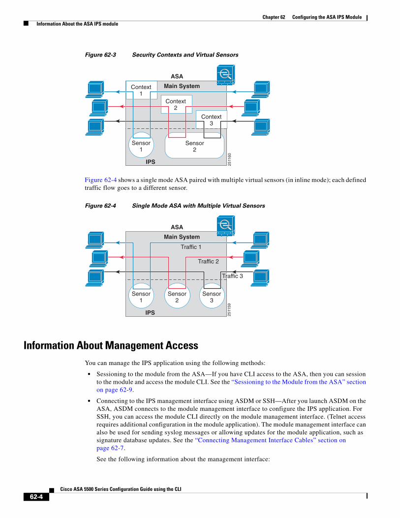
Figure 62-3 shows one security context paired with one virtual sensor (in inline mode), while two security contexts share the same virtual sensor.
ASA
Main System
inside
IPS
IPS inspection
outsideVPN
DecryptionFirewallPolicyShun
message
2511
58
Copied Traffic
62-3Cisco ASA 5500 Series Configuration Guide using the CLI
Chapter 62 Configuring the ASA IPS Module Information About the ASA IPS module
Figure 62-3 Security Contexts and Virtual Sensors
Figure 62-4 shows a single mode ASA paired with multiple virtual sensors (in inline mode); each defined traffic flow goes to a different sensor.
Figure 62-4 Single Mode ASA with Multiple Virtual Sensors
Information About Management AccessYou can manage the IPS application using the following methods:
• Sessioning to the module from the ASA—If you have CLI access to the ASA, then you can session to the module and access the module CLI. See the “Sessioning to the Module from the ASA” section on page 62-9.
• Connecting to the IPS management interface using ASDM or SSH—After you launch ASDM on the ASA, ASDM connects to the module management interface to configure the IPS application. For SSH, you can access the module CLI directly on the module management interface. (Telnet access requires additional configuration in the module application). The module management interface can also be used for sending syslog messages or allowing updates for the module application, such as signature database updates. See the “Connecting Management Interface Cables” section on page 62-7.
See the following information about the management interface:
ASA
Main System
IPS
Sensor 1
Context1
Context2
Context3
Sensor2
2511
60
Sensor1
Sensor2
Sensor3
ASA
Main System
IPS
Traffic 1
Traffic 2
Traffic 3
2511
59
62-4Cisco ASA 5500 Series Configuration Guide using the CLI
Chapter 62 Configuring the ASA IPS Module Licensing Requirements for the ASA IPS module
– ASA 5510, ASA 5520, ASA 5540, ASA 5580, ASA 5585-X—The IPS management interface is a separate external Gigabit Ethernet interface. If you cannot use the default address (see the “Default Settings” section on page 62-6), you can change the interface IP address and other network parameters. See the “Configuring Basic IPS Module Network Settings” section on page 62-10. The IPS management IP address can be on the same network as the ASA (connected through a switch), or on a different network (through a router). If you use a different network, be sure to set the IPS gateway as appropriate.
– ASA 5512-X, ASA 5515-X, ASA 5525-X, ASA 5545-X, ASA 5555-X—These models run the ASA IPS module as a software module. The IPS management interface shares the Management 0/0 interface with the ASA. Separate MAC addresses and IP addresses are supported for the ASA and ASA IPS module. You must perform configuration of the IPS IP address within the IPS operating system (using the CLI or ASDM). However, physical characteristics (such as enabling the interface) are configured on the ASA. You can change the interface IP address and other network parameters. You should set the default gateway to be an upstream router instead of the ASA management interface. Because the ASA management interface does not allow through-traffic, traffic destined to another network is not allowed through the ASA. See the “Configuring Basic IPS Module Network Settings” section on page 62-10.
– ASA 5505—You can use an ASA VLAN to allow access to an internal management IP address over the backplane. See the “(ASA 5505) Configuring Basic Network Settings” section on page 62-11 to change the network settings.
Licensing Requirements for the ASA IPS moduleThe following table shows the licensing requirements for this feature:
The ASA IPS module requires a separate Cisco Services for IPS license in order to support signature updates. All other updates are available without a license.
Guidelines and LimitationsThis section includes the guidelines and limitations for this feature.
Context Mode Guidelines
The ASA 5505 does not support multiple context mode, so multiple context features, such as virtual sensors, are not supported on the AIP SSC.
Model License Requirement
ASA 5512-X, ASA 5515-X, ASA 5525-X, ASA 5545-X, ASA 5555-X
IPS Module License.
All other models Base License.
62-5Cisco ASA 5500 Series Configuration Guide using the CLI
Chapter 62 Configuring the ASA IPS Module Default Settings
Firewall Mode Guidelines
Supported in routed and transparent firewall mode.
Model Guidelines
• See the Cisco ASA Compatibility Matrix for information about which models support which modules:
http://www.cisco.com/en/US/docs/security/asa/compatibility/asamatrx.html
• The ASA 5505 does not support multiple context mode, so multiple context features, such as virtual sensors, are not supported on the AIP SSC.
• The ASA IPS module for the ASA 5510 and higher supports higher performance requirements, while the ASA IPS module for the ASA 5505 is designed for a small office installation. The following features are not supported for the ASA 5505:
– Virtual sensors
– Anomaly detection
– Unretirement of default retired signatures
Additional Guidelines
You cannot change the software type installed on the module; if you purchase an ASA IPS module, you cannot later install other software on it.
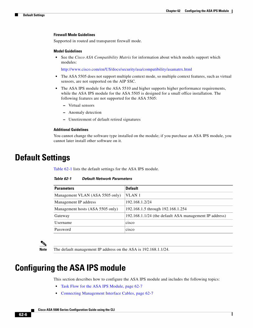
Default SettingsTable 62-1 lists the default settings for the ASA IPS module.
Note The default management IP address on the ASA is 192.168.1.1/24.
Configuring the ASA IPS moduleThis section describes how to configure the ASA IPS module and includes the following topics:
• Task Flow for the ASA IPS Module, page 62-7
• Connecting Management Interface Cables, page 62-7
Table 62-1 Default Network Parameters
Parameters Default
Management VLAN (ASA 5505 only) VLAN 1
Management IP address 192.168.1.2/24
Management hosts (ASA 5505 only) 192.168.1.5 through 192.168.1.254
Gateway 192.168.1.1/24 (the default ASA management IP address)
Username cisco
Password cisco
62-6Cisco ASA 5500 Series Configuration Guide using the CLI
Chapter 62 Configuring the ASA IPS Module Configuring the ASA IPS module
• Configuring Basic IPS Module Network Settings, page 62-10
• (ASA 5512-X through ASA 5555-X) Installing the Software Module, page 62-14
• Configuring the Security Policy on the ASA IPS module, page 62-14
• Assigning Virtual Sensors to a Security Context (ASA 5510 and Higher), page 62-15
• Diverting Traffic to the ASA IPS module, page 62-17
Task Flow for the ASA IPS ModuleConfiguring the ASA IPS module is a process that includes configuration of the IPS security policy on the ASA IPS module and then configuration of the ASA to send traffic to the ASA IPS module. To configure the ASA IPS module, perform the following steps:
Step 1 Cable the ASA and IPS management interfaces. See the “Connecting Management Interface Cables” section on page 62-7.
Step 2 Depending on your ASA model:
• (ASA 5510 and higher) Configure basic network settings for the IPS module. See the “(ASA 5510 and Higher) Configuring Basic Network Settings” section on page 62-11.
• (ASA 5505) Configure the management VLAN and IP address for the IPS module. See the “(ASA 5505) Configuring Basic Network Settings” section on page 62-11.
Step 3 (ASA 5512-X through ASA 5555-X; may be required) Install the software module. See the “(ASA 5512-X through ASA 5555-X) Installing the Software Module” section on page 62-14.
Step 4 On the module, configure the inspection and protection policy, which determines how to inspect traffic and what to do when an intrusion is detected. See the “Configuring the Security Policy on the ASA IPS module” section on page 62-14.
Step 5 (ASA 5510 and higher, optional) On the ASA in multiple context mode, specify which IPS virtual sensors are available for each context (if you configured virtual sensors). See the “Assigning Virtual Sensors to a Security Context (ASA 5510 and Higher)” section on page 62-15.
Step 6 On the ASA, identify traffic to divert to the ASA IPS module. See the “Diverting Traffic to the ASA IPS module” section on page 62-17.
Connecting Management Interface CablesConnect the management PC to the ASA management interface and the ASA IPS module management interface.
Guidelines
• Your cabling might differ depending on your network.
• See the “Information About Management Access” section on page 62-4.
62-7Cisco ASA 5500 Series Configuration Guide using the CLI
Chapter 62 Configuring the ASA IPS Module Configuring the ASA IPS module
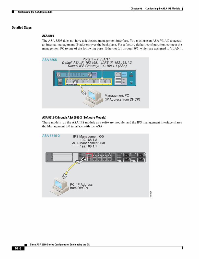
Detailed Steps
ASA 5505
The ASA 5505 does not have a dedicated management interface. You must use an ASA VLAN to access an internal management IP address over the backplane. For a factory default configuration, connect the management PC to one of the following ports: Ethernet 0/1 through 0/7, which are assigned to VLAN 1.
ASA 5512-X through ASA 5555-X (Software Module)
These models run the ASA IPS module as a software module, and the IPS management interface shares the Management 0/0 interface with the ASA.
SecurityServicesCard Slot
1
2POWER48VDC
7 POWER over ETHERNET 6 5 4 3 2 1 0
Console
RESET
Ports 1 − 7 VLAN 1 Default ASA IP: 192.168.1.1/IPS IP: 192.168.1.2
Default IPS Gateway: 192.168.1.1 (ASA)
ASA 5505
Management PC(IP Address from DHCP)
Cisco ASA SSC-05 STATUS
ASA 5545-X
PC (IP Addressfrom DHCP)
IPS Management 0/0192.168.1.2
ASA Management 0/0192.168.1.1
3311
81
62-8Cisco ASA 5500 Series Configuration Guide using the CLI
Chapter 62 Configuring the ASA IPS Module Configuring the ASA IPS module
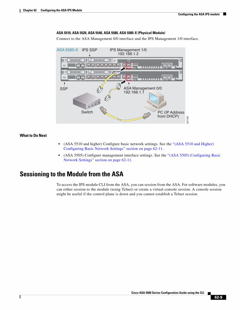
ASA 5510, ASA 5520, ASA 5540, ASA 5580, ASA 5585-X (Physical Module)
Connect to the ASA Management 0/0 interface and the IPS Management 1/0 interface.
What to Do Next
• (ASA 5510 and higher) Configure basic network settings. See the “(ASA 5510 and Higher) Configuring Basic Network Settings” section on page 62-11.
• (ASA 5505) Configure management interface settings. See the “(ASA 5505) Configuring Basic Network Settings” section on page 62-11.
Sessioning to the Module from the ASATo access the IPS module CLI from the ASA, you can session from the ASA. For software modules, you can either session to the module (using Telnet) or create a virtual console session. A console session might be useful if the control plane is down and you cannot establish a Telnet session.
ASA 5585-X
Switch
PWR
BOOT
ALARM
ACT
VPN
PS1
HDD1
PS0
HDD0USB
RESET0SFP1 SFP0 101234567 MGMT
0
1
AUX CONSOLE
PWR
BOOT
ALARM
ACT
VPN
PS1
HDD1
PS0
HDD0USB
RESET0SFP1 SFP0 101234567 MGMT
0
1
AUX CONSOLE
PC (IP Addressfrom DHCP)
ASA Management 0/0192.168.1.1
IPS Management 1/0192.168.1.2
SSP
IPS SSP
3311
82
62-9Cisco ASA 5500 Series Configuration Guide using the CLI
Chapter 62 Configuring the ASA IPS Module Configuring the ASA IPS module
Detailed Steps
Configuring Basic IPS Module Network Settings• (ASA 5510 and Higher) Configuring Basic Network Settings, page 62-11
• (ASA 5505) Configuring Basic Network Settings, page 62-11
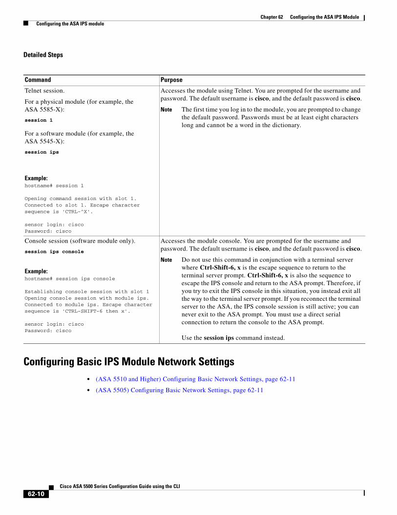
Command Purpose
Telnet session.
For a physical module (for example, the ASA 5585-X):
session 1
For a software module (for example, the ASA 5545-X):
session ips
Example:hostname# session 1
Opening command session with slot 1.Connected to slot 1. Escape character sequence is 'CTRL-^X'.
sensor login: ciscoPassword: cisco
Accesses the module using Telnet. You are prompted for the username and password. The default username is cisco, and the default password is cisco.
Note The first time you log in to the module, you are prompted to change the default password. Passwords must be at least eight characters long and cannot be a word in the dictionary.
Console session (software module only).
session ips console
Example:hostname# session ips console
Establishing console session with slot 1Opening console session with module ips.Connected to module ips. Escape character sequence is 'CTRL-SHIFT-6 then x'.
sensor login: ciscoPassword: cisco
Accesses the module console. You are prompted for the username and password. The default username is cisco, and the default password is cisco.
Note Do not use this command in conjunction with a terminal server where Ctrl-Shift-6, x is the escape sequence to return to the terminal server prompt. Ctrl-Shift-6, x is also the sequence to escape the IPS console and return to the ASA prompt. Therefore, if you try to exit the IPS console in this situation, you instead exit all the way to the terminal server prompt. If you reconnect the terminal server to the ASA, the IPS console session is still active; you can never exit to the ASA prompt. You must use a direct serial connection to return the console to the ASA prompt.
Use the session ips command instead.
62-10Cisco ASA 5500 Series Configuration Guide using the CLI
Chapter 62 Configuring the ASA IPS Module Configuring the ASA IPS module
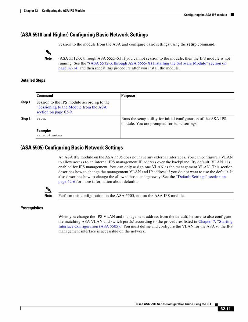
(ASA 5510 and Higher) Configuring Basic Network Settings
Session to the module from the ASA and configure basic settings using the setup command.
Note (ASA 5512-X through ASA 5555-X) If you cannot session to the module, then the IPS module is not running. See the “(ASA 5512-X through ASA 5555-X) Installing the Software Module” section on page 62-14, and then repeat this procedure after you install the module.
Detailed Steps
(ASA 5505) Configuring Basic Network Settings
An ASA IPS module on the ASA 5505 does not have any external interfaces. You can configure a VLAN to allow access to an internal IPS management IP address over the backplane. By default, VLAN 1 is enabled for IPS management. You can only assign one VLAN as the management VLAN. This section describes how to change the management VLAN and IP address if you do not want to use the default. It also describes how to change the allowed hosts and gateway. See the “Default Settings” section on page 62-6 for more information about defaults.
Note Perform this configuration on the ASA 5505, not on the ASA IPS module.
Prerequisites
When you change the IPS VLAN and management address from the default, be sure to also configure the matching ASA VLAN and switch port(s) according to the procedures listed in Chapter 7, “Starting Interface Configuration (ASA 5505).” You must define and configure the VLAN for the ASA so the IPS management interface is accessible on the network.
Command Purpose
Step 1 Session to the IPS module according to the “Sessioning to the Module from the ASA” section on page 62-9.
Step 2 setup
Example:sensor# setup
Runs the setup utility for initial configuration of the ASA IPS module. You are prompted for basic settings.
62-11Cisco ASA 5500 Series Configuration Guide using the CLI
Chapter 62 Configuring the ASA IPS Module Configuring the ASA IPS module
Restrictions
Do not configure NAT for the management address if you intend to access it using ASDM. For initial setup with ASDM, you need to access the real address. After initial setup (where you set the password on the ASA IPS module), you can configure NAT and supply ASDM with the translated address for accessing the ASA IPS module.
Detailed Steps
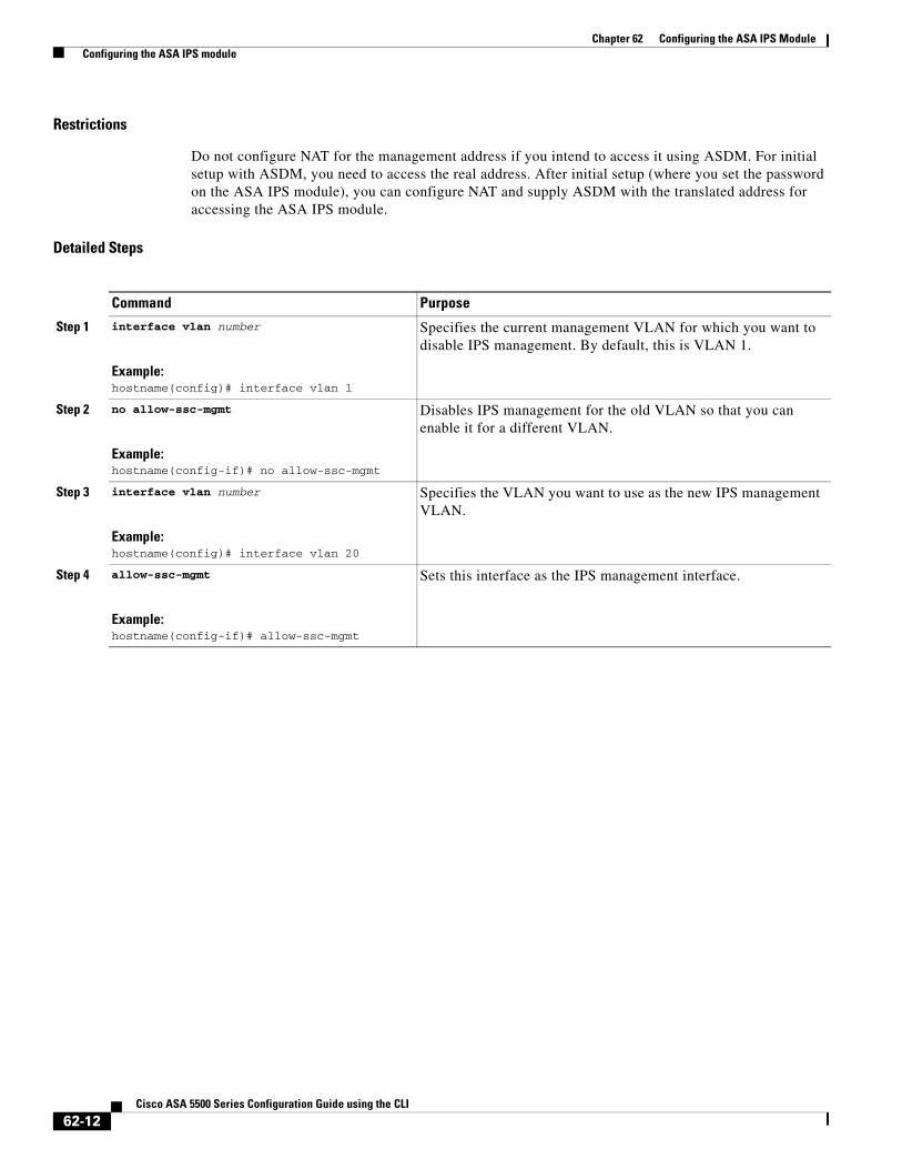
Command Purpose
Step 1 interface vlan number
Example:hostname(config)# interface vlan 1
Specifies the current management VLAN for which you want to disable IPS management. By default, this is VLAN 1.
Step 2 no allow-ssc-mgmt
Example:hostname(config-if)# no allow-ssc-mgmt
Disables IPS management for the old VLAN so that you can enable it for a different VLAN.
Step 3 interface vlan number
Example:hostname(config)# interface vlan 20
Specifies the VLAN you want to use as the new IPS management VLAN.
Step 4 allow-ssc-mgmt
Example:hostname(config-if)# allow-ssc-mgmt
Sets this interface as the IPS management interface.
62-12Cisco ASA 5500 Series Configuration Guide using the CLI
Chapter 62 Configuring the ASA IPS Module Configuring the ASA IPS module
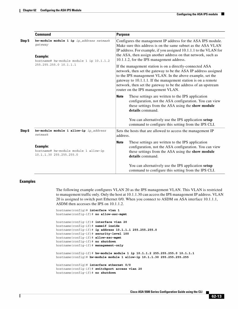
Examples
The following example configures VLAN 20 as the IPS management VLAN. This VLAN is restricted to management traffic only. Only the host at 10.1.1.30 can access the IPS management IP address. VLAN 20 is assigned to switch port Ethernet 0/0. When you connect to ASDM on ASA interface 10.1.1.1, ASDM then accesses the IPS on 10.1.1.2.
hostname(config)# interface vlan 1hostname(config-if)# no allow-ssc-mgmt
hostname(config-if)# interface vlan 20hostname(config-if)# nameif insidehostname(config-if)# ip address 10.1.1.1 255.255.255.0hostname(config-if)# security-level 100hostname(config-if)# allow-ssc-mgmthostname(config-if)# no shutdownhostname(config-if)# management-only
hostname(config-if)# hw-module module 1 ip 10.1.1.2 255.255.255.0 10.1.1.1hostname(config)# hw-module module 1 allow-ip 10.1.1.30 255.255.255.255
hostname(config)# interface ethernet 0/0hostname(config-if)# switchport access vlan 20hostname(config-if)# no shutdown
Step 5 hw-module module 1 ip ip_address netmask gateway
Example:hostname# hw-module module 1 ip 10.1.1.2 255.255.255.0 10.1.1.1
Configures the management IP address for the ASA IPS module. Make sure this address is on the same subnet as the ASA VLAN IP address. For example, if you assigned 10.1.1.1 to the VLAN for the ASA, then assign another address on that network, such as 10.1.1.2, for the IPS management address.
If the management station is on a directly-connected ASA network, then set the gateway to be the ASA IP address assigned to the IPS management VLAN. In the above example, set the gateway to 10.1.1.1. If the management station is on a remote network, then set the gateway to be the address of an upstream router on the IPS management VLAN.
Note These settings are written to the IPS application configuration, not the ASA configuration. You can view these settings from the ASA using the show module details command.
You can alternatively use the IPS application setup command to configure this setting from the IPS CLI.
Step 6 hw-module module 1 allow-ip ip_address netmask
Example:hostname# hw-module module 1 allow-ip 10.1.1.30 255.255.255.0
Sets the hosts that are allowed to access the management IP address.
Note These settings are written to the IPS application configuration, not the ASA configuration. You can view these settings from the ASA using the show module details command.
You can alternatively use the IPS application setup command to configure this setting from the IPS CLI.
Command Purpose
62-13Cisco ASA 5500 Series Configuration Guide using the CLI
Chapter 62 Configuring the ASA IPS Module Configuring the ASA IPS module
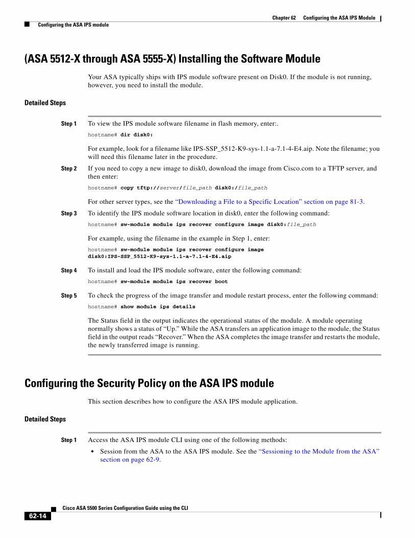
(ASA 5512-X through ASA 5555-X) Installing the Software ModuleYour ASA typically ships with IPS module software present on Disk0. If the module is not running, however, you need to install the module.
Detailed Steps
Step 1 To view the IPS module software filename in flash memory, enter:.
hostname# dir disk0:
For example, look for a filename like IPS-SSP_5512-K9-sys-1.1-a-7.1-4-E4.aip. Note the filename; you will need this filename later in the procedure.
Step 2 If you need to copy a new image to disk0, download the image from Cisco.com to a TFTP server, and then enter:
hostname# copy tftp://server/file_path disk0:/file_path
For other server types, see the “Downloading a File to a Specific Location” section on page 81-3.
Step 3 To identify the IPS module software location in disk0, enter the following command:
hostname# sw-module module ips recover configure image disk0:file_path
For example, using the filename in the example in Step 1, enter:
hostname# sw-module module ips recover configure image disk0:IPS-SSP_5512-K9-sys-1.1-a-7.1-4-E4.aip
Step 4 To install and load the IPS module software, enter the following command:
hostname# sw-module module ips recover boot
Step 5 To check the progress of the image transfer and module restart process, enter the following command:
hostname# show module ips details
The Status field in the output indicates the operational status of the module. A module operating normally shows a status of “Up.” While the ASA transfers an application image to the module, the Status field in the output reads “Recover.” When the ASA completes the image transfer and restarts the module, the newly transferred image is running.
Configuring the Security Policy on the ASA IPS moduleThis section describes how to configure the ASA IPS module application.
Detailed Steps
Step 1 Access the ASA IPS module CLI using one of the following methods:
• Session from the ASA to the ASA IPS module. See the “Sessioning to the Module from the ASA” section on page 62-9.
62-14Cisco ASA 5500 Series Configuration Guide using the CLI
Chapter 62 Configuring the ASA IPS Module Configuring the ASA IPS module
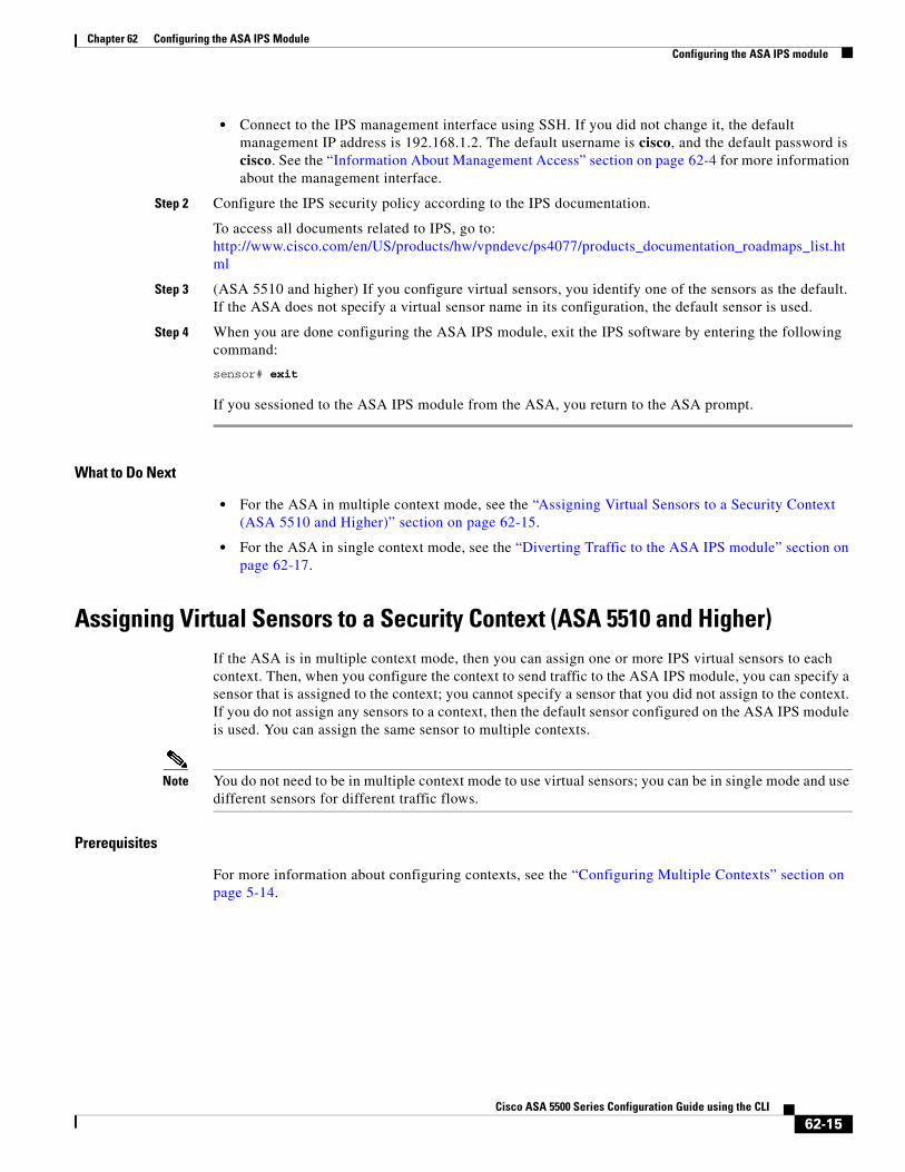
• Connect to the IPS management interface using SSH. If you did not change it, the default management IP address is 192.168.1.2. The default username is cisco, and the default password is cisco. See the “Information About Management Access” section on page 62-4 for more information about the management interface.
Step 2 Configure the IPS security policy according to the IPS documentation.
To access all documents related to IPS, go to: http://www.cisco.com/en/US/products/hw/vpndevc/ps4077/products_documentation_roadmaps_list.html
Step 3 (ASA 5510 and higher) If you configure virtual sensors, you identify one of the sensors as the default. If the ASA does not specify a virtual sensor name in its configuration, the default sensor is used.
Step 4 When you are done configuring the ASA IPS module, exit the IPS software by entering the following command:
sensor# exit
If you sessioned to the ASA IPS module from the ASA, you return to the ASA prompt.
What to Do Next
• For the ASA in multiple context mode, see the “Assigning Virtual Sensors to a Security Context (ASA 5510 and Higher)” section on page 62-15.
• For the ASA in single context mode, see the “Diverting Traffic to the ASA IPS module” section on page 62-17.
Assigning Virtual Sensors to a Security Context (ASA 5510 and Higher)If the ASA is in multiple context mode, then you can assign one or more IPS virtual sensors to each context. Then, when you configure the context to send traffic to the ASA IPS module, you can specify a sensor that is assigned to the context; you cannot specify a sensor that you did not assign to the context. If you do not assign any sensors to a context, then the default sensor configured on the ASA IPS module is used. You can assign the same sensor to multiple contexts.
Note You do not need to be in multiple context mode to use virtual sensors; you can be in single mode and use different sensors for different traffic flows.
Prerequisites
For more information about configuring contexts, see the “Configuring Multiple Contexts” section on page 5-14.
62-15Cisco ASA 5500 Series Configuration Guide using the CLI
Chapter 62 Configuring the ASA IPS Module Configuring the ASA IPS module
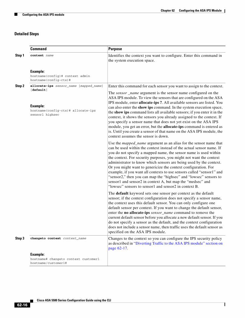
Detailed Steps
Command Purpose
Step 1 context name
Example:hostname(config)# context adminhostname(config-ctx)#
Identifies the context you want to configure. Enter this command in the system execution space.
Step 2 allocate-ips sensor_name [mapped_name] [default]
Example:hostname(config-ctx)# allocate-ips sensor1 highsec
Enter this command for each sensor you want to assign to the context.
The sensor _name argument is the sensor name configured on the ASA IPS module. To view the sensors that are configured on the ASA IPS module, enter allocate-ips ?. All available sensors are listed. You can also enter the show ips command. In the system execution space, the show ips command lists all available sensors; if you enter it in the context, it shows the sensors you already assigned to the context. If you specify a sensor name that does not yet exist on the ASA IPS module, you get an error, but the allocate-ips command is entered as is. Until you create a sensor of that name on the ASA IPS module, the context assumes the sensor is down.
Use the mapped_name argument as an alias for the sensor name that can be used within the context instead of the actual sensor name. If you do not specify a mapped name, the sensor name is used within the context. For security purposes, you might not want the context administrator to know which sensors are being used by the context. Or you might want to genericize the context configuration. For example, if you want all contexts to use sensors called “sensor1” and “sensor2,” then you can map the “highsec” and “lowsec” sensors to sensor1 and sensor2 in context A, but map the “medsec” and “lowsec” sensors to sensor1 and sensor2 in context B.
The default keyword sets one sensor per context as the default sensor; if the context configuration does not specify a sensor name, the context uses this default sensor. You can only configure one default sensor per context. If you want to change the default sensor, enter the no allocate-ips sensor_name command to remove the current default sensor before you allocate a new default sensor. If you do not specify a sensor as the default, and the context configuration does not include a sensor name, then traffic uses the default sensor as specified on the ASA IPS module.
Step 3 changeto context context_name
Example:hostname# changeto context customer1hostname/customer1#
Changes to the context so you can configure the IPS security policy as described in “Diverting Traffic to the ASA IPS module” section on page 62-17.
62-16Cisco ASA 5500 Series Configuration Guide using the CLI
Chapter 62 Configuring the ASA IPS Module Configuring the ASA IPS module
Examples
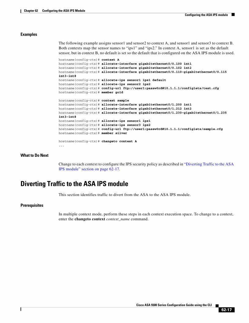
The following example assigns sensor1 and sensor2 to context A, and sensor1 and sensor3 to context B. Both contexts map the sensor names to “ips1” and “ips2.” In context A, sensor1 is set as the default sensor, but in context B, no default is set so the default that is configured on the ASA IPS module is used.
hostname(config-ctx)# context Ahostname(config-ctx)# allocate-interface gigabitethernet0/0.100 int1hostname(config-ctx)# allocate-interface gigabitethernet0/0.102 int2hostname(config-ctx)# allocate-interface gigabitethernet0/0.110-gigabitethernet0/0.115 int3-int8hostname(config-ctx)# allocate-ips sensor1 ips1 defaulthostname(config-ctx)# allocate-ips sensor2 ips2hostname(config-ctx)# config-url ftp://user1:[email protected]/configlets/test.cfghostname(config-ctx)# member gold
hostname(config-ctx)# context samplehostname(config-ctx)# allocate-interface gigabitethernet0/1.200 int1hostname(config-ctx)# allocate-interface gigabitethernet0/1.212 int2hostname(config-ctx)# allocate-interface gigabitethernet0/1.230-gigabitethernet0/1.235 int3-int8hostname(config-ctx)# allocate-ips sensor1 ips1hostname(config-ctx)# allocate-ips sensor3 ips2hostname(config-ctx)# config-url ftp://user1:[email protected]/configlets/sample.cfghostname(config-ctx)# member silver
hostname(config-ctx)# changeto context A...
What to Do Next
Change to each context to configure the IPS security policy as described in “Diverting Traffic to the ASA IPS module” section on page 62-17.
Diverting Traffic to the ASA IPS moduleThis section identifies traffic to divert from the ASA to the ASA IPS module.
Prerequisites
In multiple context mode, perform these steps in each context execution space. To change to a context, enter the changeto context context_name command.
62-17Cisco ASA 5500 Series Configuration Guide using the CLI
Chapter 62 Configuring the ASA IPS Module Configuring the ASA IPS module
Detailed Steps
Command Purpose
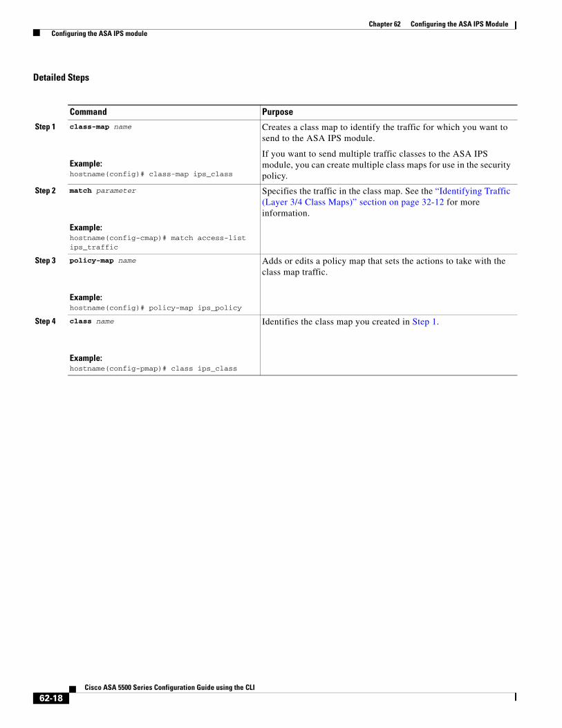
Step 1 class-map name
Example:hostname(config)# class-map ips_class
Creates a class map to identify the traffic for which you want to send to the ASA IPS module.
If you want to send multiple traffic classes to the ASA IPS module, you can create multiple class maps for use in the security policy.
Step 2 match parameter
Example:hostname(config-cmap)# match access-list ips_traffic
Specifies the traffic in the class map. See the “Identifying Traffic (Layer 3/4 Class Maps)” section on page 32-12 for more information.
Step 3 policy-map name
Example:hostname(config)# policy-map ips_policy
Adds or edits a policy map that sets the actions to take with the class map traffic.
Step 4 class name
Example:hostname(config-pmap)# class ips_class
Identifies the class map you created in Step 1.
62-18Cisco ASA 5500 Series Configuration Guide using the CLI

Chapter 62 Configuring the ASA IPS Module Configuring the ASA IPS module
Step 5 ips {inline | promiscuous} {fail-close | fail-open} [sensor {sensor_name | mapped_name}]
Example:hostname(config-pmap-c)# ips promiscuous fail-close
Specifies that the traffic should be sent to the ASA IPS module.
The inline and promiscuous keywords control the operating mode of the ASA IPS module. See the “Operating Modes” section on page 62-2 for more details.
The fail-close keyword sets the ASA to block all traffic if the ASA IPS module is unavailable.
The fail-open keyword sets the ASA to allow all traffic through, uninspected, if the ASA IPS module is unavailable.
(ASA 5510 and higher) If you use virtual sensors, you can specify a sensor name using the sensor sensor_name argument. To see available sensor names, enter the ips {inline | promiscuous} {fail-close | fail-open} sensor ? command. Available sensors are listed. You can also use the show ips command. If you use multiple context mode on the ASA, you can only specify sensors that you assigned to the context (see the “Assigning Virtual Sensors to a Security Context (ASA 5510 and Higher)” section on page 62-15). Use the mapped_name if configured in the context. If you do not specify a sensor name, then the traffic uses the default sensor. In multiple context mode, you can specify a default sensor for the context. In single mode or if you do not specify a default sensor in multiple mode, the traffic uses the default sensor that is set on the ASA IPS module. If you enter a name that does not yet exist on the ASA IPS module, you get an error, and the command is rejected.
Step 6 (Optional)
class name2
Example:hostname(config-pmap)# class ips_class2
If you created multiple class maps for IPS traffic, you can specify another class for the policy.
See the “Feature Matching Within a Service Policy” section on page 32-3 for detailed information about how the order of classes matters within a policy map. Traffic cannot match more than one class map for the same action type; so if you want network A to go to sensorA, but want all other traffic to go to sensorB, then you need to enter the class command for network A before you enter the class command for all traffic; otherwise all traffic (including network A) will match the first class command, and will be sent to sensorB.
Command Purpose
62-19Cisco ASA 5500 Series Configuration Guide using the CLI
Chapter 62 Configuring the ASA IPS Module Monitoring the ASA IPS module
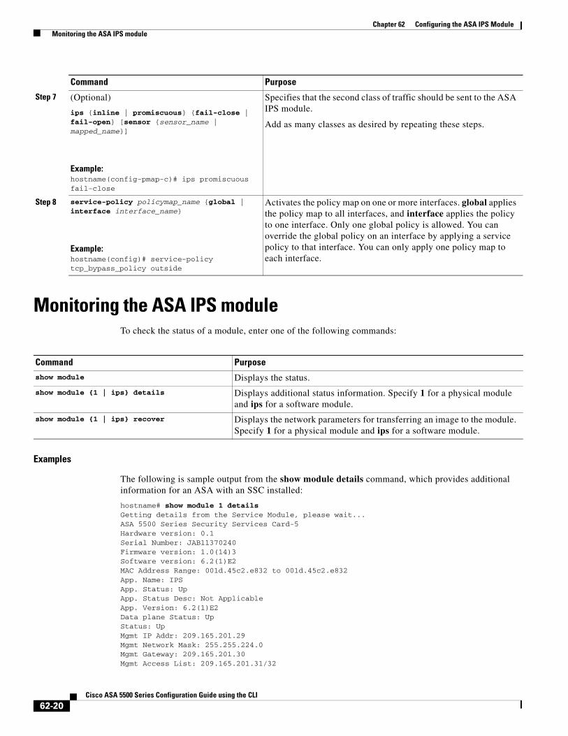
Monitoring the ASA IPS moduleTo check the status of a module, enter one of the following commands:
Examples
The following is sample output from the show module details command, which provides additional information for an ASA with an SSC installed:
hostname# show module 1 detailsGetting details from the Service Module, please wait...ASA 5500 Series Security Services Card-5Hardware version: 0.1Serial Number: JAB11370240Firmware version: 1.0(14)3Software version: 6.2(1)E2MAC Address Range: 001d.45c2.e832 to 001d.45c2.e832App. Name: IPSApp. Status: UpApp. Status Desc: Not ApplicableApp. Version: 6.2(1)E2Data plane Status: UpStatus: UpMgmt IP Addr: 209.165.201.29Mgmt Network Mask: 255.255.224.0Mgmt Gateway: 209.165.201.30 Mgmt Access List: 209.165.201.31/32
Step 7 (Optional)
ips {inline | promiscuous} {fail-close | fail-open} [sensor {sensor_name | mapped_name}]
Example:hostname(config-pmap-c)# ips promiscuous fail-close
Specifies that the second class of traffic should be sent to the ASA IPS module.
Add as many classes as desired by repeating these steps.
Step 8 service-policy policymap_name {global | interface interface_name}
Example:hostname(config)# service-policy tcp_bypass_policy outside
Activates the policy map on one or more interfaces. global applies the policy map to all interfaces, and interface applies the policy to one interface. Only one global policy is allowed. You can override the global policy on an interface by applying a service policy to that interface. You can only apply one policy map to each interface.
Command Purpose
Command Purpose
show module Displays the status.
show module {1 | ips} details Displays additional status information. Specify 1 for a physical module and ips for a software module.
show module {1 | ips} recover Displays the network parameters for transferring an image to the module. Specify 1 for a physical module and ips for a software module.
62-20Cisco ASA 5500 Series Configuration Guide using the CLI
Chapter 62 Configuring the ASA IPS Module Troubleshooting the ASA IPS module
209.165.202.158/32209.165.200.254/24
Mgmt Vlan: 20
Troubleshooting the ASA IPS moduleThis section includes procedures that help you recover or troubleshoot the module and includes the following topics:
• Installing an Image on the Module, page 62-21
• Uninstalling a Software Module Image, page 62-23
• Resetting the Password, page 62-23
• Reloading or Resetting the Module, page 62-24
• Shutting Down the Module, page 62-24
Installing an Image on the Module
If the module suffers a failure, and the module application image cannot run, you can reinstall a new image on the module from a TFTP server (for a physical module), or from the local disk (software module).
Note Do not use the upgrade command within the module software to install the image.
Prerequisites
• Physical module—Be sure the TFTP server that you specify can transfer files up to 60 MB in size.
Note This process can take approximately 15 minutes to complete, depending on your network and the size of the image.
• Software module—Copy the image to the ASA internal flash (disk0) before completing this procedure.
Note Before you download the IPS software to disk0, make sure at least 50% of the flash memory is free. When you install IPS, IPS reserves 50% of the internal flash memory for its file system.
62-21Cisco ASA 5500 Series Configuration Guide using the CLI
Chapter 62 Configuring the ASA IPS Module Troubleshooting the ASA IPS module
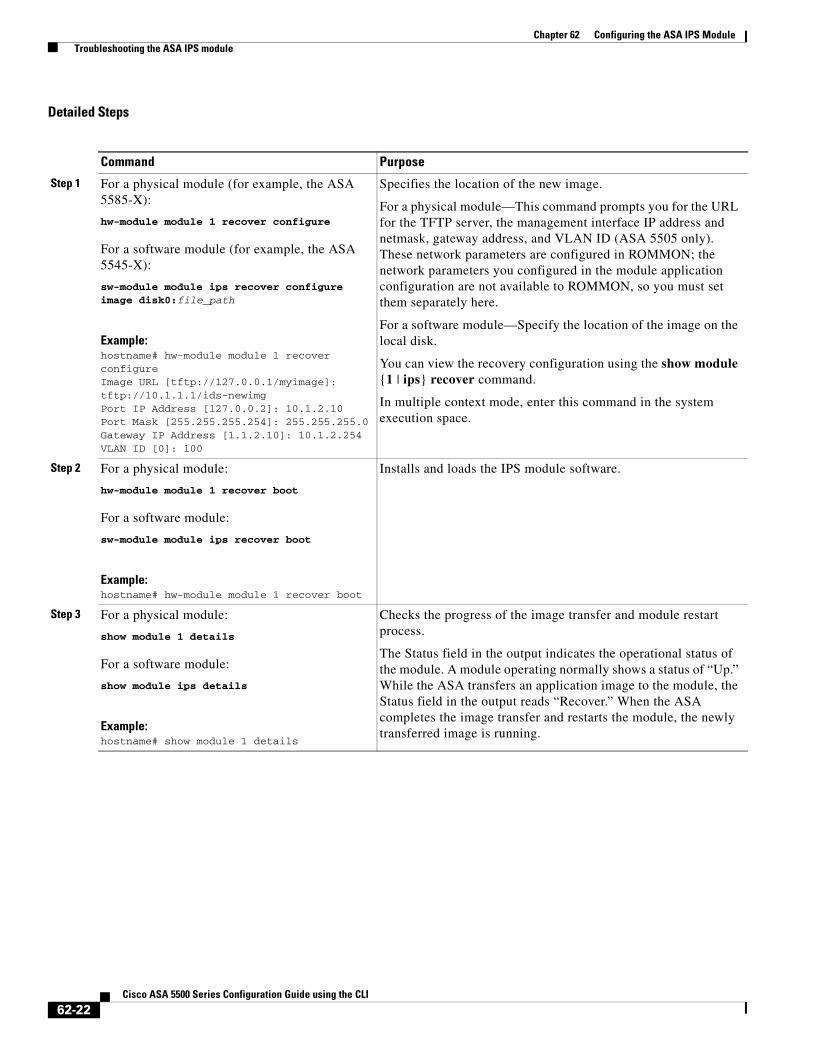
Detailed Steps
Command Purpose
Step 1 For a physical module (for example, the ASA 5585-X):
hw-module module 1 recover configure
For a software module (for example, the ASA 5545-X):
sw-module module ips recover configure image disk0:file_path
Example:hostname# hw-module module 1 recover configureImage URL [tftp://127.0.0.1/myimage]: tftp://10.1.1.1/ids-newimgPort IP Address [127.0.0.2]: 10.1.2.10Port Mask [255.255.255.254]: 255.255.255.0Gateway IP Address [1.1.2.10]: 10.1.2.254VLAN ID [0]: 100
Specifies the location of the new image.
For a physical module—This command prompts you for the URL for the TFTP server, the management interface IP address and netmask, gateway address, and VLAN ID (ASA 5505 only). These network parameters are configured in ROMMON; the network parameters you configured in the module application configuration are not available to ROMMON, so you must set them separately here.
For a software module—Specify the location of the image on the local disk.
You can view the recovery configuration using the show module {1 | ips} recover command.
In multiple context mode, enter this command in the system execution space.
Step 2 For a physical module:
hw-module module 1 recover boot
For a software module:
sw-module module ips recover boot
Example:hostname# hw-module module 1 recover boot
Installs and loads the IPS module software.
Step 3 For a physical module:
show module 1 details
For a software module:
show module ips details
Example:hostname# show module 1 details
Checks the progress of the image transfer and module restart process.
The Status field in the output indicates the operational status of the module. A module operating normally shows a status of “Up.” While the ASA transfers an application image to the module, the Status field in the output reads “Recover.” When the ASA completes the image transfer and restarts the module, the newly transferred image is running.
62-22Cisco ASA 5500 Series Configuration Guide using the CLI
Chapter 62 Configuring the ASA IPS Module Troubleshooting the ASA IPS module
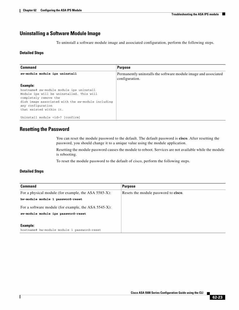
Uninstalling a Software Module Image
To uninstall a software module image and associated configuration, perform the following steps.
Detailed Steps
Resetting the Password
You can reset the module password to the default. The default password is cisco. After resetting the password, you should change it to a unique value using the module application.
Resetting the module password causes the module to reboot. Services are not available while the module is rebooting.
To reset the module password to the default of cisco, perform the following steps.
Detailed Steps
Command Purposesw-module module ips uninstall
Example:hostname# sw-module module ips uninstallModule ips will be uninstalled. This will completely remove thedisk image associated with the sw-module including any configurationthat existed within it.
Uninstall module <id>? [confirm]
Permanently uninstalls the software module image and associated configuration.
Command Purpose
For a physical module (for example, the ASA 5585-X):
hw-module module 1 password-reset
For a software module (for example, the ASA 5545-X):
sw-module module ips password-reset
Example:hostname# hw-module module 1 password-reset
Resets the module password to cisco.
62-23Cisco ASA 5500 Series Configuration Guide using the CLI
Chapter 62 Configuring the ASA IPS Module Troubleshooting the ASA IPS module
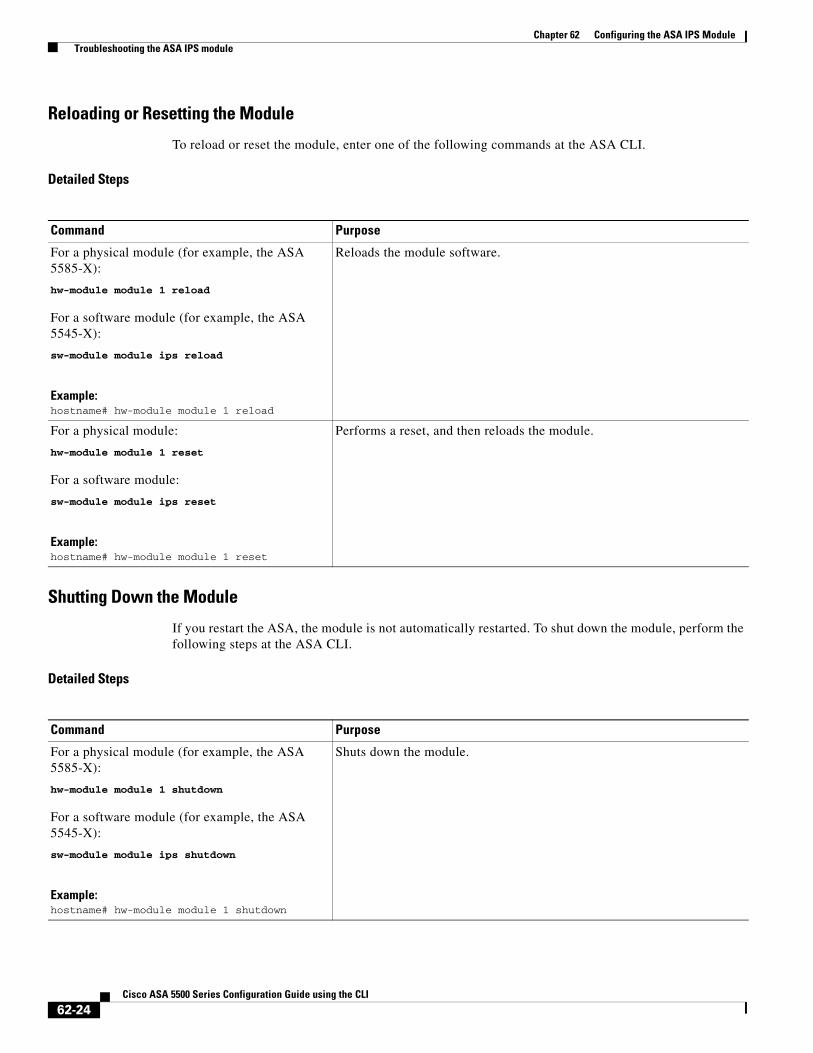
Reloading or Resetting the Module
To reload or reset the module, enter one of the following commands at the ASA CLI.
Detailed Steps
Shutting Down the Module
If you restart the ASA, the module is not automatically restarted. To shut down the module, perform the following steps at the ASA CLI.
Detailed Steps
Command Purpose
For a physical module (for example, the ASA 5585-X):
hw-module module 1 reload
For a software module (for example, the ASA 5545-X):
sw-module module ips reload
Example:hostname# hw-module module 1 reload
Reloads the module software.
For a physical module:
hw-module module 1 reset
For a software module:
sw-module module ips reset
Example:hostname# hw-module module 1 reset
Performs a reset, and then reloads the module.
Command Purpose
For a physical module (for example, the ASA 5585-X):
hw-module module 1 shutdown
For a software module (for example, the ASA 5545-X):
sw-module module ips shutdown
Example:hostname# hw-module module 1 shutdown
Shuts down the module.
62-24Cisco ASA 5500 Series Configuration Guide using the CLI
Chapter 62 Configuring the ASA IPS Module Configuration Examples for the ASA IPS module
Configuration Examples for the ASA IPS moduleThe following example diverts all IP traffic to the ASA IPS module in promiscuous mode, and blocks all IP traffic if the ASA IPS module card fails for any reason:
hostname(config)# access-list IPS permit ip any anyhostname(config)# class-map my-ips-classhostname(config-cmap)# match access-list IPShostname(config-cmap)# policy-map my-ips-policyhostname(config-pmap)# class my-ips-classhostname(config-pmap-c)# ips promiscuous fail-closehostname(config-pmap-c)# service-policy my-ips-policy global
The following example diverts all IP traffic destined for the 10.1.1.0 network and the 10.2.1.0 network to the AIP SSM in inline mode, and allows all traffic through if the AIP SSM fails for any reason. For the my-ips-class traffic, sensor1 is used; for the my-ips-class2 traffic, sensor2 is used.
hostname(config)# access-list my-ips-acl permit ip any 10.1.1.0 255.255.255.0hostname(config)# access-list my-ips-acl2 permit ip any 10.2.1.0 255.255.255.0hostname(config)# class-map my-ips-classhostname(config-cmap)# match access-list my-ips-aclhostname(config)# class-map my-ips-class2hostname(config-cmap)# match access-list my-ips-acl2hostname(config-cmap)# policy-map my-ips-policyhostname(config-pmap)# class my-ips-classhostname(config-pmap-c)# ips inline fail-open sensor sensor1hostname(config-pmap)# class my-ips-class2hostname(config-pmap-c)# ips inline fail-open sensor sensor2hostname(config-pmap-c)# service-policy my-ips-policy interface outside
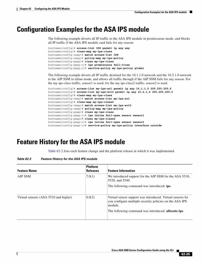
Feature History for the ASA IPS moduleTable 62-2 lists each feature change and the platform release in which it was implemented.
Table 62-2 Feature History for the ASA IPS module
Feature NamePlatform Releases Feature Information
AIP SSM 7.0(1) We introduced support for the AIP SSM for the ASA 5510, 5520, and 5540.
The following command was introduced: ips.
Virtual sensors (ASA 5510 and higher) 8.0(2) Virtual sensor support was introduced. Virtual sensors let you configure multiple security policies on the ASA IPS module.
The following command was introduced: allocate-ips.
62-25Cisco ASA 5500 Series Configuration Guide using the CLI
Chapter 62 Configuring the ASA IPS Module Feature History for the ASA IPS module
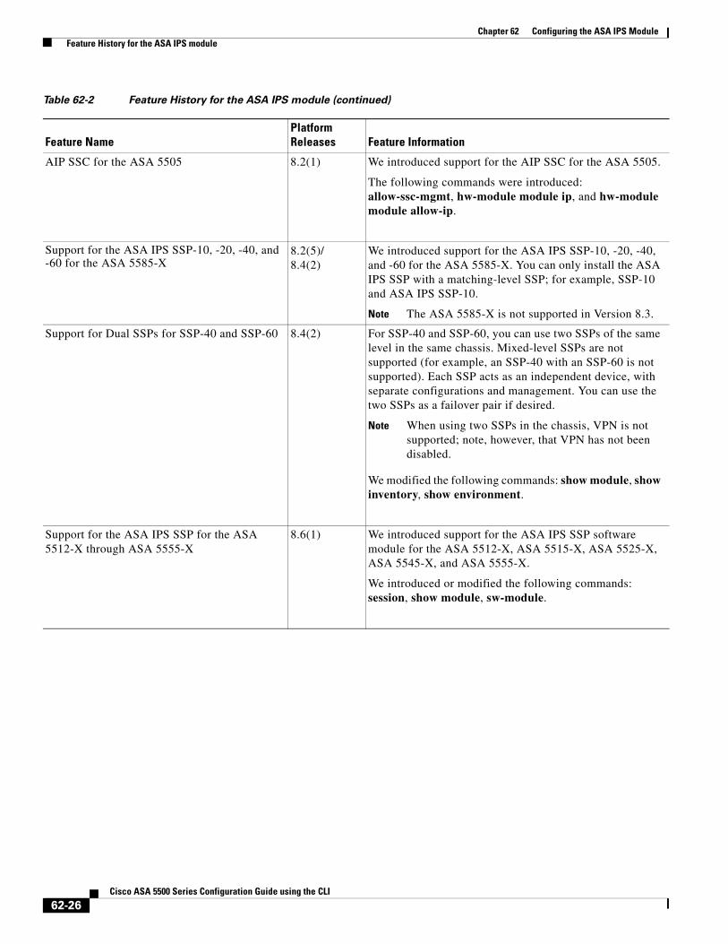
AIP SSC for the ASA 5505 8.2(1) We introduced support for the AIP SSC for the ASA 5505.
The following commands were introduced: allow-ssc-mgmt, hw-module module ip, and hw-module module allow-ip.
Support for the ASA IPS SSP-10, -20, -40, and -60 for the ASA 5585-X
8.2(5)/8.4(2)
We introduced support for the ASA IPS SSP-10, -20, -40, and -60 for the ASA 5585-X. You can only install the ASA IPS SSP with a matching-level SSP; for example, SSP-10 and ASA IPS SSP-10.
Note The ASA 5585-X is not supported in Version 8.3.
Support for Dual SSPs for SSP-40 and SSP-60 8.4(2) For SSP-40 and SSP-60, you can use two SSPs of the same level in the same chassis. Mixed-level SSPs are not supported (for example, an SSP-40 with an SSP-60 is not supported). Each SSP acts as an independent device, with separate configurations and management. You can use the two SSPs as a failover pair if desired.
Note When using two SSPs in the chassis, VPN is not supported; note, however, that VPN has not been disabled.
We modified the following commands: show module, show inventory, show environment.
Support for the ASA IPS SSP for the ASA 5512-X through ASA 5555-X
8.6(1) We introduced support for the ASA IPS SSP software module for the ASA 5512-X, ASA 5515-X, ASA 5525-X, ASA 5545-X, and ASA 5555-X.
We introduced or modified the following commands: session, show module, sw-module.
Table 62-2 Feature History for the ASA IPS module (continued)
Feature NamePlatform Releases Feature Information
62-26Cisco ASA 5500 Series Configuration Guide using the CLI