Embed Size (px)
Citation preview
Catalyst 3750 Metr78-15870-01
C H A P T E R 30
Configuring MPLS and EoMPLSThis chapter describes how to configure multiprotocol label switching (MPLS) and Ethernet over MPLS (EoMPLS) on the Catalyst 3750 Metro switch. MPLS is a packet-switching technology that integrates link layer (Layer 2) switching with network layer (Layer 3) routing. With MPLS, data is transferred over any combination of Layer 2 technologies, using any Layer 3 protocol, with increased scalability. MPLS supports different routes between a source and destination over a router-based Internet backbone.
EoMPLS is tunneling mechanism that transports Layer 2 Ethernet frames over an MPLS network. You can connect two Layer 2 networks that are in different locations, without requiring bridges, routers, or switches at the locations. You enable the MPLS backbone to accept Layer 2 traffic by configuring the label-edge routers (LERs) at both ends of the MPLS backbone.
MPLS functionality is supported only on the enhanced-services (ES) ports; EoMPLS is supported on standard and ES ports.
Note For more information about MPLS, refer to the Cisco IOS Switching Services Configuration Guide for Release 12.l. For complete syntax and usage information for the MPLS commands used in this chapter, refer to the Cisco IOS Switching Services Command Reference for Release 12.l.For more information about EoMPLS commands, refer also to the command reference for this release.
This chapter contains these sections:
• Understanding MPLS Services, page 30-1
• Understanding MPLS VPNs, page 30-2
• Configuring MPLS VPNs, page 30-6
• Understanding EoMPLS, page 30-12
• Enabling EoMPLS, page 30-15
• Configuring MPLS and EoMPLS QoS, page 30-18
• Monitoring and Maintaining MPLS and EoMPLS, page 30-22
Understanding MPLS ServicesIn conventional Layer 3 forwarding, as a packet travels across the network, each router extracts the packet-forwarding information from the Layer 3 header and uses this information as an index for a routing table lookup to determine the packet's next hop. In most cases, the only relevant field in the header is the destination address field, but in some cases other header fields are also relevant. For this reason, each router through which the packet passes must analyze the packet header.
30-1o Switch Software Configuration Guide
Chapter 30 Configuring MPLS and EoMPLSUnderstanding MPLS VPNs
With MPLS, the Layer 3 header is analyzed only once and then is mapped into a fixed-length, unstructured value called a label. Many different headers can map to the same label, as long as those headers always result in the same choice of next hop. In effect, a label represents a forwarding-equivalence class—that is, a set of packets that can be very different but that are indistinguishable to the forwarding function.
The initial choice of label can be based exclusively on the contents of the Layer 3 header, or it can be based on policy, allowing forwarding decisions at subsequent hops to be based on policy. After a label is chosen, a short label header is put at the front of the Layer 3 packet and carried across the network as part of the packet. At subsequent hops through each MPLS router in the network, labels are exchanged, and the router uses MPLS forwarding-table lookups for the label to make forwarding decisions. It is not necessary to re-analyze the packet header. Because the label is a fixed length and unstructured, the MPLS forwarding-table lookup process is straightforward and fast.
Each label-switching router (LSR) in the network makes an independent, local decision as to which label value is used to represent which forwarding equivalence class. This association is known as a label binding. Each LSR informs its neighbors of the label bindings that it has made. When a labeled packet is sent from LSR A to neighboring LSR B, the label value carried by the packet is the label value that B assigned to represent the packet's forwarding equivalence class. Thus, the label value changes as the IP packet travels through the network.
Note Because the Catalyst 3750 Metro switch is used as a service-provider edge (PE) device, rather than a service-provider core router, it does not normally operate as an LSR. The switch only performs label switching when it is connected to two different provider core routers over the ES ports to provide a redundant path. In this case, the switch uses QoS policies to classify MPLS packets on egress for label switching.
A label represents a forwarding-equivalence class, but it does not represent a particular path through the network. In general, the path through the network continues to be chosen by the existing Layer 3 routing protocols, such as Open Shortest Path First (OSPF), Enhanced Interior Gateway Protocol (EIGRP), Intermediate-System-to-Intermediate-System (IS-IS), and Border Gateway Protocol (BGP). At each hop when a label is looked up, the choice of the next hop is determined by the dynamic routing algorithm.
Understanding MPLS VPNsUsing MPLS virtual private networks (VPNs) provides the capability to deploy and administer scalable Layer 3 VPN backbone services to business customers. A VPN is a secure IP-based network that shares resources on one or more physical networks. A VPN contains geographically dispersed sites that can communicate securely over a shared backbone.
VPN routes are distributed over the MPLS network by using multiprotocol BGP (MP-BGP), which also distributes the labels associated with each VPN route. MPLS VPN depends on VPN routing and forwarding (VRF) support to isolate the routing domains from each other. When routes are learned over an MPLS VPN, the switch learns the new route as a normal VRF route, except that the destination MAC address for the next hop is not the real address, but a specially formed address that contains an identifier that is allocated for the route. When an MPLS-VPN packet is received on a port, the switch looks up the labels in the routing table to determine what to do with the packet.
30-2Catalyst 3750 Metro Switch Software Configuration Guide
78-15870-01
Chapter 30 Configuring MPLS and EoMPLSUnderstanding MPLS VPNs
Each VPN is associated with one or more VPN VRF instances. A VRF includes routing and forwarding tables and rules that define the VPN membership of customer devices attached to the customer edge (CE) device. A customer site can be a member of multiple VPNs; however, a site can associate with only one VRF. A VRF has these elements:
• An IP routing table
• A Cisco Express Forwarding (CEF) table
• A set of interfaces that use the CEF forwarding table
• A set of rules and routing protocol parameters to control the information in the routing tables
A customer-site VRF contains all the routes available to the site from the VPNs to which it belongs. VPN routing information is stored in the IP routing table and the CEF table for each VRF. A separate set of tables is maintained for each VRF, which prevents information from being forwarded outside a VPN and prevents packets that are outside a VPN from being forwarded to a router within the VPN. Based on the routing information stored in the VRF IP routing table and the VRF CEF table, packets are forwarded to their destinations.
A PE router binds a label to each customer prefix that is learned from a CE device and includes the label in the network reachability information for the prefix that it advertises to other PE routers. When a PE router forwards a packet that is received from a CE device across the provider network, it labels the packet with the label learned from the destination PE router. When the destination PE router receives the labeled packet, it examines the label and uses it to direct the packet to the correct CE device. A customer data-packet carries two levels of labels when traversing the backbone:
• The top label directs the packet to the correct PE router.
• The second label defines how that PE router should forward the packet to the CE device.
VPN BenefitsMPLS VPNs allow service providers to deploy scalable VPNs and build the foundation to deliver value-added services, including:
• Connectionless service—MPLS VPNs are connectionless, which means that no prior action is required to establish communication between hosts. A connectionless VPN does not require tunnels and encryption for network privacy.
• Centralized service—MPLS VPNs are seen as private intranets, which allows delivery of targeted IP services to a group of users represented by a VPN.
• Scalability— MPLS-based VPNs use the peer model and Layer 3 connectionless architecture to leverage a highly scalable solution. The peer model requires a customer site to act as a peer to one PE router as opposed to all other customer provider-edge or CE devices that are members of the VPN. The PE routers maintain VPN routes for those VPNs who are members. Routers in the core network do not maintain any VPN routes.
• Security—MPLS VPNs offer the same level of security as connection-oriented VPNs. Packets from one VPN do not inadvertently go to another VPN. Security provided at the edge of a provider network ensures that packets received from a customer are placed on the correct VPN; security provided at the backbone ensures that VPN traffic is kept separate.
• Easy to create—Because MPLS VPNs are connectionless, no specific point-to-point connection maps or topologies are required, and you can add sites to intranets and extranets to form closed user groups.
30-3Catalyst 3750 Metro Switch Software Configuration Guide
78-15870-01
Chapter 30 Configuring MPLS and EoMPLSUnderstanding MPLS VPNs
• Flexible addressing—Customers can continue to use their present address spaces without network address translation (NAT) because the MPLS VPN provides a public and private view of the address. A NAT is required only if two VPNs with overlapping address spaces want to communicate.
• Straightforward migration—You can build MPLS VPNs over multiple network architectures. Migration for the end customer is simplified because the CE router is not required to support MPLS, so no customer's intranet modifications are needed.
• MPLS VPN also provides increased BGP functionality.
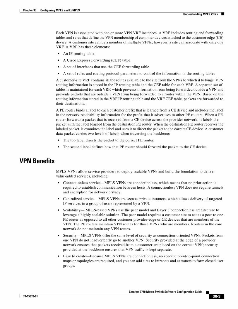
Figure 30-1 shows an example of a VPN with a service-provider backbone network, PE routers, and CE devices.
Figure 30-1 VPNs with a Service-Provider Backbone
Each VPN contains customer devices attached to the CE devices. The customer devices use VPNs to exchange information between devices, and the provider routers (P) are not aware of the VPNs.
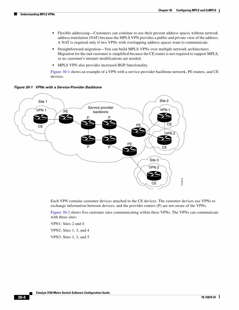
Figure 30-2 shows five customer sites communicating within three VPNs. The VPNs can communicate with these sites:
VPN1: Sites 2 and 4
VPN2: Sites 1, 3, and 4
VPN3: Sites 1, 3, and 5
CE
PE
PE
CE
PE CE
CE
P
Service providerbackbone
Site 1
Site 3
Site 2
VPN 1 VPN 1
VPN 2
VPN 2
P
P
P
1018
19
30-4Catalyst 3750 Metro Switch Software Configuration Guide
78-15870-01
Chapter 30 Configuring MPLS and EoMPLSUnderstanding MPLS VPNs
Figure 30-2 Customer Sites with VPNs
Distribution of VPN Routing InformationThe distribution of VPN routing information is controlled through the use of VPN route target communities, implemented by BGP extended communities. VPN routing information is distributed in this manner:
• When a VPN route learned from a CE device is added to the BGP process, a list of VPN route target extended community attributes is associated with it. The attribute values are obtained from an export list of route targets associated with the VRF from which the route was learned.
• An import list of route target extended communities is also associated with each VRF. The import list defines route target extended community attributes that a route must have in order for the route to be imported into the VRF. For example, if the import list for a particular VRF includes route target communities A, B, and C, then any VPN route that carries any of those route target extended communities—A, B, or C—is imported into the VRF.
A PE router can learn an IP prefix from a CE device by static configuration, through a BGP session with the CE device, or through the routing information protocol (RIP) exchange with the CE router. The IP prefix is a member of the IPv4 address family. After it learns the IP prefix, the PE converts it into a VPN-IPv4 prefix by combining it with an 8-byte route distinguisher (RD). The generated prefix is a member of the VPN-IPv4 address family and uniquely identifies the customer address, even if the customer site is using globally nonunique (unregistered private) IP addresses.
BGP distributes reachability information for VPN-IPv4 prefixes for each VPN. BGP communication takes place at two levels: within IP domains, known as autonomous systems (internal BGP or IBGP), and between autonomous systems (external BGP or EBGP). PE-to-PE sessions are IBGP sessions, and PE-CE sessions are EBGP sessions.
BGP propagates reachability information for VPN-IPv4 prefixes among PE routers by using the BGP multiprotocol extensions, which define support for address families other than IPv4. It does this in a way that ensures that the routes for a given VPN are learned only by other members of that VPN, which enables members of the VPN to communicate with each other.
Site 2
VPN1VPN2
VPN3
Site 4
Site 5
1726
6
Site 3
Site 1
30-5Catalyst 3750 Metro Switch Software Configuration Guide
78-15870-01
Chapter 30 Configuring MPLS and EoMPLSConfiguring MPLS VPNs
Configuring MPLS VPNsThis section includes this information about configuring MPLS VPNs on a Catalyst 3750 Metro switch used as a PE router:
• Default MPLS Configuration, page 30-6
• MPLS VPN Configuration Guidelines, page 30-6
These sections describe the required tasks:
• Enabling MPLS, page 30-7
• Defining VPNs, page 30-8
• Configuring BGP Routing Sessions, page 30-9
• Configuring PE-to-PE Routing Sessions, page 30-9
You must also configure a PE to CE routing session. These sections provide example configurations:
• Configuring BGP PE-to-CE Routing Sessions, page 30-10
• Configuring RIP PE-to-CE Routing Sessions, page 30-10
• Configuring Static Route PE-to-CE Routing Sessions, page 30-11
For an example of packet flow in an MPLS VPN, see the “Packet Flow in an MPLS VPN” section on page 30-11.
Default MPLS ConfigurationBy default, label switching of IPv4 packets along normally routed paths is globally enabled. MPLS forwarding of IPv4 packets is disabled by default on interfaces.
If no distribution protocol is explicitly configured by the mpls label protocol global configuration command, tag distribution protocol (TDP) is the default label distribution protocol for the switch. Cisco recommends that you configure label distribution protocol (LDP) for MPLS.
If no protocol is explicitly configured for an interface, the default label distribution protocol for the switch is used. By default, the labels of all destinations are advertised to all LDP neighbors.
No VRFs are defined. The default routing table for an interface is the global routing table.
MPLS VPN Configuration GuidelinesMPLS requires that CEF is enabled on the switch. CEF is enabled by default. For more information about CEF, refer to the “Configuring Cisco Express Forwarding” section on page 28-86.
The switch must connect to the MPLS network through an ES port. MPLS configuration is supported only on ES ports.
Do not configure VLAN mapping on an interface configured for MPLS.
The switch supports a total of 26 VRFs and VPNs.
VRFs are not compatible with the PBR template. If you configure the PBR template by entering the sdm prefer routing-pbr command, any preconfigured VRFs are removed from the configuration. PBR and VRFs cannot function on the same switch.
30-6Catalyst 3750 Metro Switch Software Configuration Guide
78-15870-01
Chapter 30 Configuring MPLS and EoMPLSConfiguring MPLS VPNs
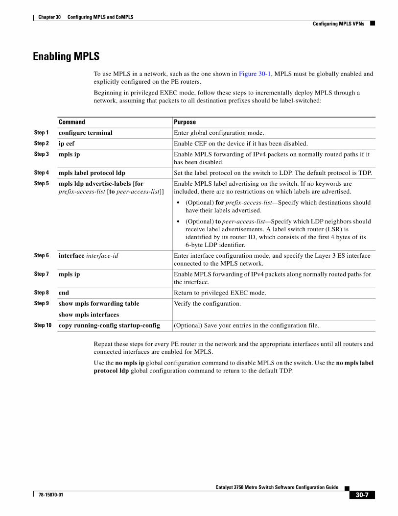
Enabling MPLSTo use MPLS in a network, such as the one shown in Figure 30-1, MPLS must be globally enabled and explicitly configured on the PE routers.
Beginning in privileged EXEC mode, follow these steps to incrementally deploy MPLS through a network, assuming that packets to all destination prefixes should be label-switched:
Repeat these steps for every PE router in the network and the appropriate interfaces until all routers and connected interfaces are enabled for MPLS.
Use the no mpls ip global configuration command to disable MPLS on the switch. Use the no mpls label protocol ldp global configuration command to return to the default TDP.
Command Purpose
Step 1 configure terminal Enter global configuration mode.
Step 2 ip cef Enable CEF on the device if it has been disabled.
Step 3 mpls ip Enable MPLS forwarding of IPv4 packets on normally routed paths if it has been disabled.
Step 4 mpls label protocol ldp Set the label protocol on the switch to LDP. The default protocol is TDP.
Step 5 mpls ldp advertise-labels [for prefix-access-list [to peer-access-list]]
Enable MPLS label advertising on the switch. If no keywords are included, there are no restrictions on which labels are advertised.
• (Optional) for prefix-access-list—Specify which destinations should have their labels advertised.
• (Optional) to peer-access-list—Specify which LDP neighbors should receive label advertisements. A label switch router (LSR) is identified by its router ID, which consists of the first 4 bytes of its 6-byte LDP identifier.
Step 6 interface interface-id Enter interface configuration mode, and specify the Layer 3 ES interface connected to the MPLS network.
Step 7 mpls ip Enable MPLS forwarding of IPv4 packets along normally routed paths for the interface.
Step 8 end Return to privileged EXEC mode.
Step 9 show mpls forwarding table
show mpls interfaces
Verify the configuration.
Step 10 copy running-config startup-config (Optional) Save your entries in the configuration file.
30-7Catalyst 3750 Metro Switch Software Configuration Guide
78-15870-01
Chapter 30 Configuring MPLS and EoMPLSConfiguring MPLS VPNs
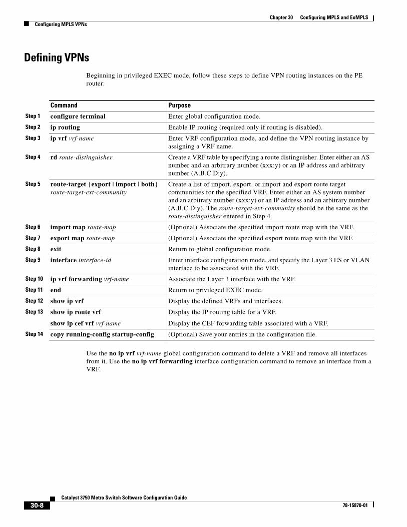
Defining VPNsBeginning in privileged EXEC mode, follow these steps to define VPN routing instances on the PE router:
Use the no ip vrf vrf-name global configuration command to delete a VRF and remove all interfaces from it. Use the no ip vrf forwarding interface configuration command to remove an interface from a VRF.
Command Purpose
Step 1 configure terminal Enter global configuration mode.
Step 2 ip routing Enable IP routing (required only if routing is disabled).
Step 3 ip vrf vrf-name Enter VRF configuration mode, and define the VPN routing instance by assigning a VRF name.
Step 4 rd route-distinguisher Create a VRF table by specifying a route distinguisher. Enter either an AS number and an arbitrary number (xxx:y) or an IP address and arbitrary number (A.B.C.D:y).
Step 5 route-target {export | import | both} route-target-ext-community
Create a list of import, export, or import and export route target communities for the specified VRF. Enter either an AS system number and an arbitrary number (xxx:y) or an IP address and an arbitrary number (A.B.C.D:y). The route-target-ext-community should be the same as the route-distinguisher entered in Step 4.
Step 6 import map route-map (Optional) Associate the specified import route map with the VRF.
Step 7 export map route-map (Optional) Associate the specified export route map with the VRF.
Step 8 exit Return to global configuration mode.
Step 9 interface interface-id Enter interface configuration mode, and specify the Layer 3 ES or VLAN interface to be associated with the VRF.
Step 10 ip vrf forwarding vrf-name Associate the Layer 3 interface with the VRF.
Step 11 end Return to privileged EXEC mode.
Step 12 show ip vrf Display the defined VRFs and interfaces.
Step 13 show ip route vrf
show ip cef vrf vrf-name
Display the IP routing table for a VRF.
Display the CEF forwarding table associated with a VRF.
Step 14 copy running-config startup-config (Optional) Save your entries in the configuration file.
30-8Catalyst 3750 Metro Switch Software Configuration Guide
78-15870-01
Chapter 30 Configuring MPLS and EoMPLSConfiguring MPLS VPNs
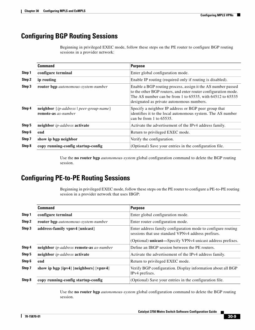
Configuring BGP Routing SessionsBeginning in privileged EXEC mode, follow these steps on the PE router to configure BGP routing sessions in a provider network:
Use the no router bgp autonomous-system global configuration command to delete the BGP routing session.
Configuring PE-to-PE Routing SessionsBeginning in privileged EXEC mode, follow these steps on the PE router to configure a PE-to-PE routing session in a provider network that uses IBGP:
Use the no router bgp autonomous-system global configuration command to delete the BGP routing session.
Command Purpose
Step 1 configure terminal Enter global configuration mode.
Step 2 ip routing Enable IP routing (required only if routing is disabled).
Step 3 router bgp autonomous-system-number Enable a BGP routing process, assign it the AS number passed to the other BGP routers, and enter router configuration mode. The AS number can be from 1 to 65535, with 64512 to 65535 designated as private autonomous numbers.
Step 4 neighbor {ip-address | peer-group-name} remote-as as-number
Specify a neighbor IP address or BGP peer group that identifies it to the local autonomous system. The AS number can be from 1 to 65535.
Step 5 neighbor ip-address activate Activate the advertisement of the IPv4 address family.
Step 6 end Return to privileged EXEC mode.
Step 7 show ip bgp neighbor Verify the configuration.
Step 8 copy running-config startup-config (Optional) Save your entries in the configuration file.
Command Purpose
Step 1 configure terminal Enter global configuration mode.
Step 2 router bgp autonomous-system-number Enter router configuration mode.
Step 3 address-family vpnv4 [unicast] Enter address family configuration mode to configure routing sessions that use standard VPNv4 address prefixes.
(Optional) unicast—Specify VPNv4 unicast address prefixes.
Step 4 neighbor ip-address remote-as as-number Define an IBGP session between the PE routers.
Step 5 neighbor ip-address activate Activate the advertisement of the IPv4 address family.
Step 6 end Return to privileged EXEC mode.
Step 7 show ip bgp [ipv4] [neighbors] [vpnv4] Verify BGP configuration. Display information about all BGP IPv4 prefixes.
Step 8 copy running-config startup-config (Optional) Save your entries in the configuration file.
30-9Catalyst 3750 Metro Switch Software Configuration Guide
78-15870-01
Chapter 30 Configuring MPLS and EoMPLSConfiguring MPLS VPNs
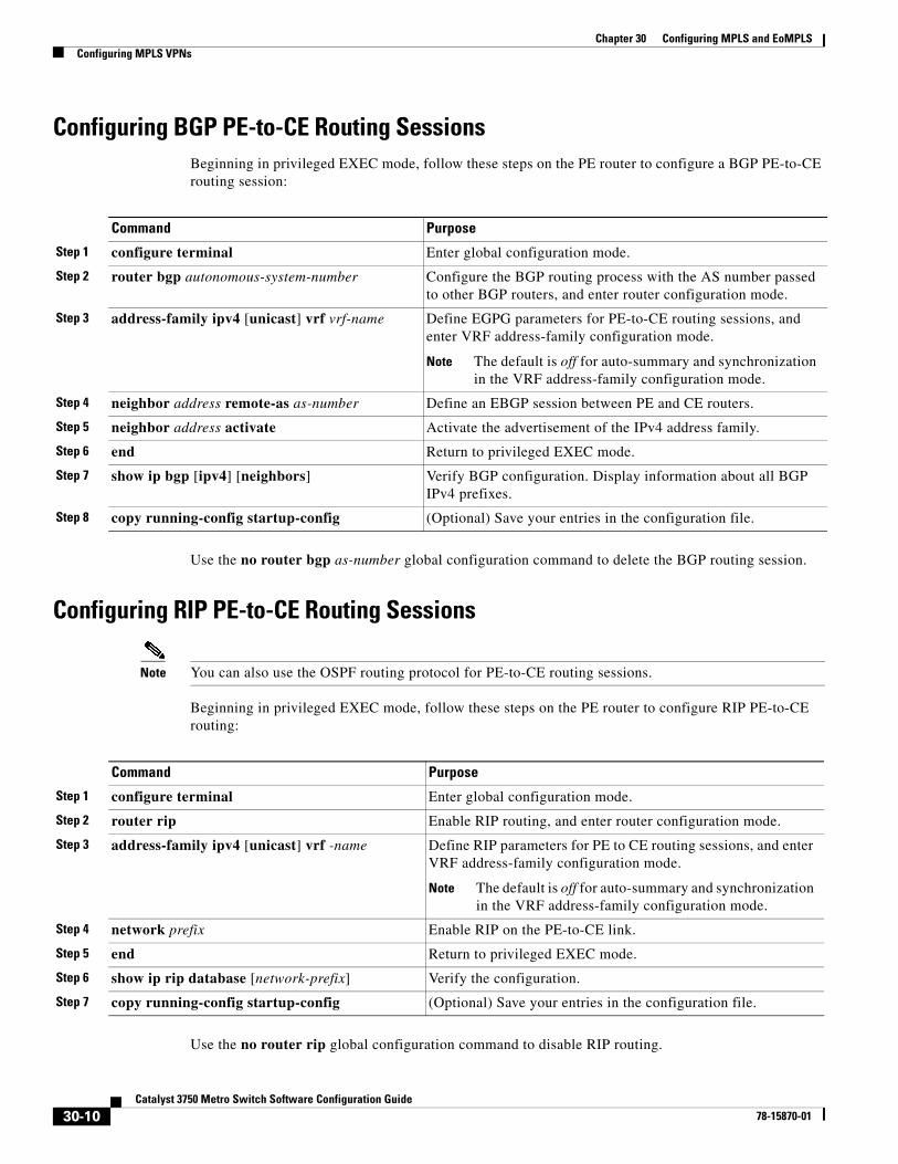
Configuring BGP PE-to-CE Routing SessionsBeginning in privileged EXEC mode, follow these steps on the PE router to configure a BGP PE-to-CE routing session:
Use the no router bgp as-number global configuration command to delete the BGP routing session.
Configuring RIP PE-to-CE Routing Sessions
Note You can also use the OSPF routing protocol for PE-to-CE routing sessions.
Beginning in privileged EXEC mode, follow these steps on the PE router to configure RIP PE-to-CE routing:
Use the no router rip global configuration command to disable RIP routing.
Command Purpose
Step 1 configure terminal Enter global configuration mode.
Step 2 router bgp autonomous-system-number Configure the BGP routing process with the AS number passed to other BGP routers, and enter router configuration mode.
Step 3 address-family ipv4 [unicast] vrf vrf-name Define EGPG parameters for PE-to-CE routing sessions, and enter VRF address-family configuration mode.
Note The default is off for auto-summary and synchronization in the VRF address-family configuration mode.
Step 4 neighbor address remote-as as-number Define an EBGP session between PE and CE routers.
Step 5 neighbor address activate Activate the advertisement of the IPv4 address family.
Step 6 end Return to privileged EXEC mode.
Step 7 show ip bgp [ipv4] [neighbors] Verify BGP configuration. Display information about all BGP IPv4 prefixes.
Step 8 copy running-config startup-config (Optional) Save your entries in the configuration file.
Command Purpose
Step 1 configure terminal Enter global configuration mode.
Step 2 router rip Enable RIP routing, and enter router configuration mode.
Step 3 address-family ipv4 [unicast] vrf -name Define RIP parameters for PE to CE routing sessions, and enter VRF address-family configuration mode.
Note The default is off for auto-summary and synchronization in the VRF address-family configuration mode.
Step 4 network prefix Enable RIP on the PE-to-CE link.
Step 5 end Return to privileged EXEC mode.
Step 6 show ip rip database [network-prefix] Verify the configuration.
Step 7 copy running-config startup-config (Optional) Save your entries in the configuration file.
30-10Catalyst 3750 Metro Switch Software Configuration Guide
78-15870-01
Chapter 30 Configuring MPLS and EoMPLSConfiguring MPLS VPNs
Configuring Static Route PE-to-CE Routing SessionsBeginning in privileged EXEC mode, follow these steps on the PE router to configure static routing:
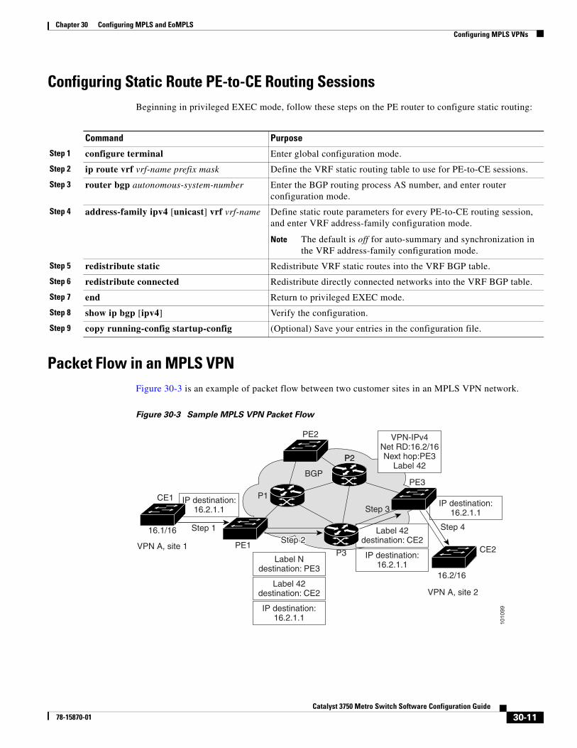
Packet Flow in an MPLS VPNFigure 30-3 is an example of packet flow between two customer sites in an MPLS VPN network.
Figure 30-3 Sample MPLS VPN Packet Flow
Command Purpose
Step 1 configure terminal Enter global configuration mode.
Step 2 ip route vrf vrf-name prefix mask Define the VRF static routing table to use for PE-to-CE sessions.
Step 3 router bgp autonomous-system-number Enter the BGP routing process AS number, and enter router configuration mode.
Step 4 address-family ipv4 [unicast] vrf vrf-name Define static route parameters for every PE-to-CE routing session, and enter VRF address-family configuration mode.
Note The default is off for auto-summary and synchronization in the VRF address-family configuration mode.
Step 5 redistribute static Redistribute VRF static routes into the VRF BGP table.
Step 6 redistribute connected Redistribute directly connected networks into the VRF BGP table.
Step 7 end Return to privileged EXEC mode.
Step 8 show ip bgp [ipv4] Verify the configuration.
Step 9 copy running-config startup-config (Optional) Save your entries in the configuration file.
1010
99IP destination:
16.2.1.1
Label 42destination: CE2
IP destination:16.2.1.1
16.2/16
16.1/16
VPN A, site 1
CE1 IP destination:16.2.1.1
Label Ndestination: PE3
Label 42destination: CE2
IP destination:16.2.1.1
VPN A, site 2
CE2
PE3
P2P2
Step 1
Step 3
Step 4
PE2
P1
PE1
BGP
VPN-IPv4Net RD:16.2/16Next hop:PE3
Label 42
Step 2Step 2
P3
30-11Catalyst 3750 Metro Switch Software Configuration Guide
78-15870-01
Chapter 30 Configuring MPLS and EoMPLSUnderstanding EoMPLS
A customer (Fast Ethernet) port on switch PE1 is configured for routed operation in a VPN. The port uses static routing or a routing protocol (RIP, OSPF, EIGRP, or BGP) to forward packets. MP-BGP is configured over the PE1 switch ES port with a route distinguisher (RD) that is associated with the customer’s VPN. MP-BGP is configured to redistribute the routes and their associated VPN labels over the ES port that is using this RD.
The packet flow follows these steps:
Step 1 Provider-edge switch PE1 (which could be a Catalyst 3750 Metro switch) receives a packet from the customer switch at site 1. The switch determines from the lookup table that the VRF is a VLAN running MPLS and uses the MPLS lookup table to determine what to do with the packet. The MPLS lookup table contains the peer LSR as the destination MAC address and the local interface as the source MAC address.
Step 2 PE1 finds a BGP route with the appropriate next hop and labels, adds the appropriate labels to the packet, and forwards the packet out of the ES port to the next hop router (P3).
Step 3 The P3 router receives the packet and forwards it over the MPLS-VPN network, based on the packet’s top label—the interior gateway protocol (IGP) label—and then removes the top label.
Step 4 PE3 receives the packet, removes the MPLS encapsulation, and forwards the packet by using the VRF interface associated with the VPN label contained in the packet that has the customer-edge switch CE2 as the destination.
Understanding EoMPLSAny Transport over MPLS (AToM) is a solution for transporting Layer 2 packets over an MPLS network, allowing service providers to use the MPLS network to provide connectivity between customer sites with existing Layer 2 networks. Instead of separate networks with network management environments, service providers can use the MPLS network to transport all types of traffic for different customers. The Catalyst 3750 Metro switch supports EoMPLS, a subset of AToM that uses a tunneling mechanism to carry Layer 2 Ethernet traffic.EoMPLS encapsulates Ethernet frames in MPLS packets and forwards them across the MPLS network. Each frame is transported as a single packet, and the PE routers connected to the backbone add and remove labels as appropriate for packet encapsulation:
• The ingress PE router receives an Ethernet frame and encapsulates the packet by removing the preamble, the start of frame delimiter (SFD), and the frame check sequence (FCS). The rest of the packet header is not changed.
• The ingress PE router adds a point-to-point virtual connection (VC) label and a label switched path (LSP) tunnel label for normal MPLS routing through the MPLS backbone.
• The network core routers use the LSP tunnel label to move the packet through the MPLS backbone and do not distinguish Ethernet traffic from any other types of packets in the MPLS backbone.
• At the other end of the MPLS backbone, the egress PE router receives the packet and de-encapsulates the packet by removing the LSP tunnel label if one is present. The PE router also removes the VC label from the packet.
• The PE router updates the header, if necessary, and sends the packet out the appropriate interface to the destination switch.
The MPLS backbone uses the tunnel labels to transport the packet between the PE routers. The egress PE router uses the VC label to select the outgoing interface for the Ethernet packet. EoMPLS tunnels are unidirectional; for bidirectional EoMPLS, you need to configure one tunnel in each direction.
30-12Catalyst 3750 Metro Switch Software Configuration Guide
78-15870-01
Chapter 30 Configuring MPLS and EoMPLSUnderstanding EoMPLS
The point-to-point VC requires you to configure VC endpoints at the two PE routers. Only the PE routers at the ingress and egress points of the MPLS backbone know about the VCs dedicated to transporting Layer 2 traffic. Other routers do not have table entries for these VCs.
This section includes additional information about these topics:
• Interaction with Other Features, page 30-13
• EoMPLS Limitations, page 30-14
Interaction with Other FeaturesThis section describes how EoMPLS interacts other features. It includes these sections:
• EoMPLS and 802.1Q Tunneling, page 30-13
• EoMPLS and Layer 2 Tunneling, page 30-14
• EoMPLS and QoS, page 30-14
EoMPLS and 802.1Q Tunneling
IEEE 802.1Q tunneling enables service providers to use a single VLAN to support customers who have multiple VLANs, while preserving customer VLAN IDs and segregating traffic in different VLANs. For more information about 802.1Q tunneling, see Chapter 13, “Configuring IEEE 802.1Q and Layer 2 Protocol Tunneling.”
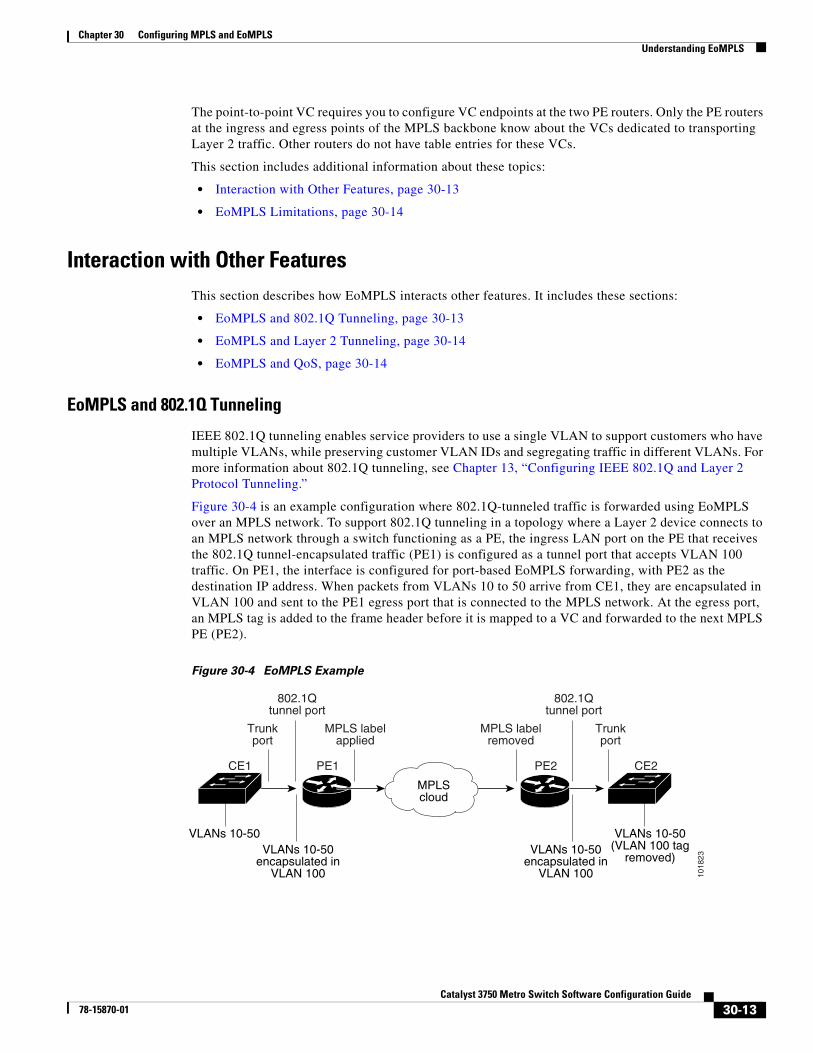
Figure 30-4 is an example configuration where 802.1Q-tunneled traffic is forwarded using EoMPLS over an MPLS network. To support 802.1Q tunneling in a topology where a Layer 2 device connects to an MPLS network through a switch functioning as a PE, the ingress LAN port on the PE that receives the 802.1Q tunnel-encapsulated traffic (PE1) is configured as a tunnel port that accepts VLAN 100 traffic. On PE1, the interface is configured for port-based EoMPLS forwarding, with PE2 as the destination IP address. When packets from VLANs 10 to 50 arrive from CE1, they are encapsulated in VLAN 100 and sent to the PE1 egress port that is connected to the MPLS network. At the egress port, an MPLS tag is added to the frame header before it is mapped to a VC and forwarded to the next MPLS PE (PE2).
Figure 30-4 EoMPLS Example
VLANs 10-50(VLAN 100 tag
removed)
CE1 CE2PE1 PE2
1018
23
MPLScloud
VLANs 10-50VLANs 10-50
encapsulated inVLAN 100
VLANs 10-50encapsulated in
VLAN 100
802.1Qtunnel port
802.1Qtunnel port
Trunkport
Trunkport
MPLS labelapplied
MPLS labelremoved
30-13Catalyst 3750 Metro Switch Software Configuration Guide
78-15870-01
Chapter 30 Configuring MPLS and EoMPLSUnderstanding EoMPLS
By entering the mpls l2transport route or the xconnect interface configuration command on either a VLAN for VLAN-based EoMPLS or an Ethernet port for port-based EoMPLS, you can configure an EoMPLS tunnel to forward traffic based on either the customer VLAN or the Ethernet port.
• To forward 802.1Q tunnel-encapsulated traffic through the MPLS core to a specific recipient on the other side of the MPLS network, configure port-based EoMPLS.
• To forward 802.1Q tunnel-encapsulated traffic from an access device to a PE router, configure VLAN-based EoMPLS.
EoMPLS and Layer 2 Tunneling
Layer 2 protocol tunneling over an EoMPLS link allows CDP, STP, and VTP protocol data units (PDUs) to be tunneled through an MPLS network. To support Layer 2 protocol tunneling when the Layer 2 device connects to an MPLS network through a switch functioning as a PE, you configure the ingress port on the PE that receives the Layer 2 protocol traffic as a tunnel port. The Layer 2 protocol traffic is encapsulated before it is forwarded over the MPLS network. For more information about Layer 2 protocol tunneling, see Chapter 13, “Configuring IEEE 802.1Q and Layer 2 Protocol Tunneling.”
EoMPLS and QoS
EoMPLS supports QoS by using three experimental bits in a label to determine the priority of packets. To support QoS between label edge routers (LERs), you set the experimental bits in both the VC and tunnel labels. EoMPLS QoS classification occurs on ingress, and you can only match on Layer 3 parameters (such as IP or DSCP), not Layer 2 parameters (CoS). See the “Configuring MPLS and EoMPLS QoS” section on page 30-18 for more information about EoMPLS and QoS.
EoMPLS LimitationsThese restrictions apply to EoMPLS:
• EoMPLS requires that at least one of the two ES ports be configured for MPLS. Therefore, if you want to run EoMPLS on an ES port, you can only configure it on the ES port that is not configured for MPLS.
• MTU—EoMPLS does not support packet fragmentation and reassembly. Therefore, the maximum transmission unit (MTU) of all intermediate links between endpoints must be sufficient to carry the largest Layer 2 VLAN received. The ingress and egress PE routers must have the same MTU value.
• Address Format—All loopback addresses on PE routers must be configured with 32-bit masks to ensure proper operation of MPLS forwarding. OSPF requires the use of loopback addresses.
• Packet Format—EoMPLS supports VLAN packets that conform to the IEEE 802.1Q standard. ISL encapsulation is not supported between PE and CE routers.
• The maximum number of VLANs using EoMPLS on a switch is 1005.
• Layer 2 connection restrictions:
– You cannot have a direct Layer 2 connection between PEs with EoMPLS.
– You cannot have more than one Layer 2 connection between routers if those routers are configured to transport Ethernet VLANs over the MPLS backbone. Adding a second Layer 2 connection causes the spanning-tree state to constantly toggle if you disable spanning tree on the peer router.
30-14Catalyst 3750 Metro Switch Software Configuration Guide
78-15870-01
Chapter 30 Configuring MPLS and EoMPLSEnabling EoMPLS
• EoMPLS and trunking restrictions:
– To support Ethernet spanning-tree bridge protocol data units (BPDUs) across an EoMPLS backbone, you must disable spanning tree for the EoMPLS VLAN. This ensures that the EoMPLS VLANs are carried only on the trunk to the customer switch.
– The native VLAN of a trunk cannot be an EoMPLS VLAN.
• You can enable EoMPLS on 802.1Q interfaces by using the mpls l2transport route or the xconnect interface configuration command.
• Do not configure VLAN mapping on an interface configured for EoMPLS.
Enabling EoMPLSThis section includes this information about configuring EoMPLS on a switch used as a PE router:
• Default EoMPLS Configuration, page 30-15
• EoMPLS Configuration Guidelines, page 30-15
• Configuring EoMPLS, page 30-16
• Packet Flow in an EoMPLS Network, page 30-17
Default EoMPLS ConfigurationBy default, EoMPLS is not configured.
The mpls ldp router-id command is disabled. No virtual connections are configured.
EoMPLS Configuration GuidelinesWhen you configure EoMPLS, you must follow these guidelines:
• EoMPLS requires that at least one of the two ES ports be configured for MPLS. Therefore, if you want to run EoMPLS on an ES port, you can only configure it on the ES port that is not configured for MPLS.
• Before enabling EoMPLS, you must enable dynamic MPLS labeling by using the mpls ip interface configuration command on all paths between the imposition and disposition LERs. MPLS is globally enabled by default.
• For VLAN-based EoMPLS, you must configure VLANs on the switch.
• EoMPLS operation between two PE routers requires an LDP session between the routers. The IP address used by each router as its LDP router ID must be IP-reachable by the other. Use the optional mpls ldp router-id global configuration command to control the selection of the LDP router ID by specifying the interface whose IP address should be used.
– If the specified interface is up and has an IP address, you can use the command without the optional force keyword. When the router ID is selected, that IP address is selected as the router ID.
– If the specified interface is not up or does not have an IP address, use the force keyword with the command to ensure that the IP address of the specified interface is used when that interface is brought up.
30-15Catalyst 3750 Metro Switch Software Configuration Guide
78-15870-01
Chapter 30 Configuring MPLS and EoMPLSEnabling EoMPLS
• Both PE routers require a loopback address that you can use to create a VC between the routers. When you use OSPF as the interior gateway protocol, you must configure all loopback addresses on PE routers with 32-bit masks to ensure proper operation of MPLS forwarding between the PE routers.
• Do not configure EoMPLS on an interface configured for VLAN mapping.
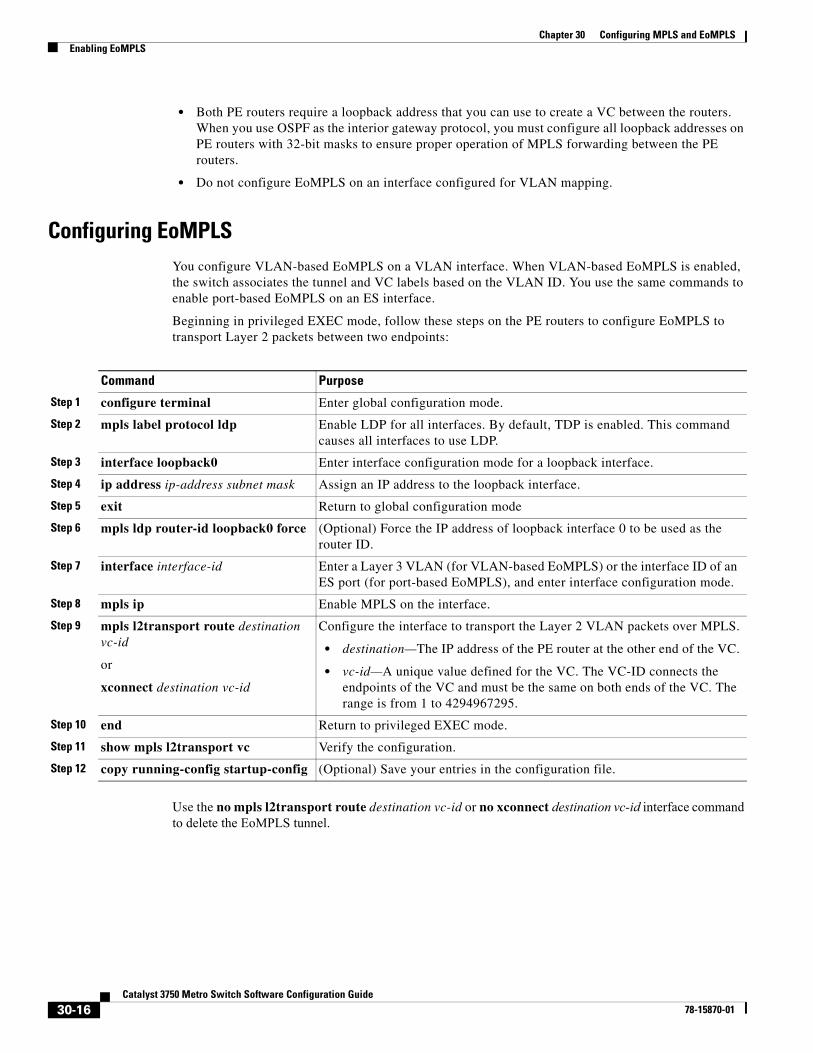
Configuring EoMPLSYou configure VLAN-based EoMPLS on a VLAN interface. When VLAN-based EoMPLS is enabled, the switch associates the tunnel and VC labels based on the VLAN ID. You use the same commands to enable port-based EoMPLS on an ES interface.
Beginning in privileged EXEC mode, follow these steps on the PE routers to configure EoMPLS to transport Layer 2 packets between two endpoints:
Use the no mpls l2transport route destination vc-id or no xconnect destination vc-id interface command to delete the EoMPLS tunnel.
Command Purpose
Step 1 configure terminal Enter global configuration mode.
Step 2 mpls label protocol ldp Enable LDP for all interfaces. By default, TDP is enabled. This command causes all interfaces to use LDP.
Step 3 interface loopback0 Enter interface configuration mode for a loopback interface.
Step 4 ip address ip-address subnet mask Assign an IP address to the loopback interface.
Step 5 exit Return to global configuration mode
Step 6 mpls ldp router-id loopback0 force (Optional) Force the IP address of loopback interface 0 to be used as the router ID.
Step 7 interface interface-id Enter a Layer 3 VLAN (for VLAN-based EoMPLS) or the interface ID of an ES port (for port-based EoMPLS), and enter interface configuration mode.
Step 8 mpls ip Enable MPLS on the interface.
Step 9 mpls l2transport route destination vc-id
or
xconnect destination vc-id
Configure the interface to transport the Layer 2 VLAN packets over MPLS.
• destination—The IP address of the PE router at the other end of the VC.
• vc-id—A unique value defined for the VC. The VC-ID connects the endpoints of the VC and must be the same on both ends of the VC. The range is from 1 to 4294967295.
Step 10 end Return to privileged EXEC mode.
Step 11 show mpls l2transport vc Verify the configuration.
Step 12 copy running-config startup-config (Optional) Save your entries in the configuration file.
30-16Catalyst 3750 Metro Switch Software Configuration Guide
78-15870-01
Chapter 30 Configuring MPLS and EoMPLSEnabling EoMPLS
This example shows how to configure an EoMPLS tunnel between switch PE1’s VLAN 3 interface and PE2’s VLAN 4 interface.
PE1 has an IP address 10.0.0.1/32, and PE2 has IP address 20.0.01/32. Both PE routers are configured with an MPLS connection to the MPLS core. The VC ID is 123.
Enter these commands on the PE1 switch:
Switch(config)# interface loopback0Switch(config-if)# ip address 10.10.10.10 255.255.255.255Switch(config-if)# exitSwitch(config)# interface vlan 3Switch(config-if)# mpls ipSwitch(config-if)# mpls l2transport route 20.0.0.1 123
Enter these commands on the PE2 switch:
Switch(config)# interface loopback0Switch(config-if)# ip address 20.20.20.20 255.255.255.255Switch(config-if)# exitSwitch(config)# interface vlan 4Switch(config-if)# mpls ipSwitch(config-if)# mpls l2transport route 10.0.0.1 123
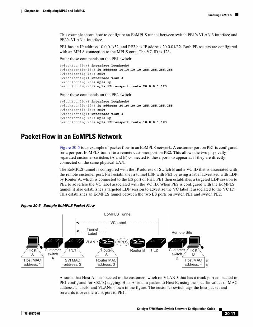
Packet Flow in an EoMPLS NetworkFigure 30-5 is an example of packet flow in an EoMPLS network. A customer port on PE1 is configured for a per-port EoMPLS tunnel to a remote customer port on PE2. This allows the two physically separated customer switches (A and B) connected to these ports to appear as if they are directly connected on the same physical LAN.
The EoMPLS tunnel is configured with the IP address of Switch B and a VC ID that is associated with the remote customer port. PE1 establishes a tunnel LSP with PE2 by using a label advertised with LDP by Router A, which is connected to the ES port of PE1. PE1 then establishes a targeted LDP session to PE2 to advertise the VC label associated with the VC ID. When PE2 is configured with the EoMPLS tunnel, it also establishes a targeted LDP session to advertise the VC label it associated to the VC ID. This establishes an EoMPLS tunnel between the two ES ports on switch PE1 and switch PE2.
Figure 30-5 Sample EoMPLS Packet Flow
Assume that Host A is connected to the customer switch on VLAN 3 that has a trunk port connected to PE1 configured for 802.1Q tagging. Host A sends a packet to Host B, using the specific values of MAC addresses, labels, and VLANs shown in the figure. The customer switch tags the host packet and forwards it over the trunk port to PE1.
VLAN 7
HostA
PE1 Router B
Remote Site
VC Label
EoMPLS Tunnel
1011
00
MPLS
Customerswitch
A
Customerswitch
BHost MACaddress: 1
SVI MACaddress: 2
HostB
Host MACaddress: 4
PE2RouterA
Router MACaddress: 3
TunnelLabel
30-17Catalyst 3750 Metro Switch Software Configuration Guide
78-15870-01
Chapter 30 Configuring MPLS and EoMPLSConfiguring MPLS and EoMPLS QoS
The tagged packet is received on the CE port that is configured for per-port EoMPLS tunneling. The PE1 switch examines the packet headers and looks at the tables stored in the switch to determine what to do with the packet. Because the port is configured for per-port EoMPLS tunneling, the switch does not remove any VLAN tags that are in the packet, but assigns the packet to an internal VLAN. Only the customer port and the ES port are configured with that internal VLAN, which makes the PE1 ES port the only possible destination for the packet.
The ES port encapsulates the packet header with the tunnel label and the VC label and forwards the packet to the next hop, in this case Router A, for it to be sent across the MPLS network.
The router receives the packet and forwards it over the MPLS network to the remote PE2 switch. PE2 removes the MPLS encapsulation and sends the packet out of the port associated with the VC label. Customer Switch B removes the final VLAN tag and forwards the packet to the remote host B.
VLAN-based EoMPLS packet flow is basically the same as port-based EoMPLS, except that the customer VLAN is used instead of an internal VLAN. The PE1 switch looks up the customer VLAN ID to determine that the packet is forwarded to the ES port, where the packets is again examined and encapsulated with the tunnel label and VC label based on the EoMPLS for that VLAN.
Configuring MPLS and EoMPLS QoSQuality of service (QoS) in MPLS and EoMPLS enables network administrators to provide differentiated types of service across an MPLS network. Each packet can receive the particular kind of service specified by the packet QoS. To preserve QoS IP precedence bits, you must globally disable QoS.
After you enable QoS, you can preserve Differentiated Services Code Point (DSCP) or IP precedence bits by using a trusted configuration at the interface level. For more information, see the “Configuring Ingress Classification by Using Port Trust States” section on page 26-42. However, the unpreserved bits are automatically overwritten by the value of the preserved bits. For example, if you preserve the DSCP bits, the IP precedence and CoS bits are overwritten with the value of the DSCP bits. You can also set MPLS and EoMPLS QoS priority by using 3 experimental bits in the MPLS label to determine the priority of packets.
Note The switch supports only DSCP and IP precedence classification for MPLS and EoMPLS.
This section contains this information:
• Understanding MPLS QoS, page 30-18
• Enabling MPLS and EoMPLS QoS, page 30-20
Understanding MPLS QoSService in an MPLS network can be specified in different ways, for example, by using the IP precedence bit settings in IP packets. When you send IP packets from one site to another, the IP precedence field (the first 3 bits of the DSCP field in the header of an IP packet) specifies the QoS. Based on the IP precedence marking, the packet is given the desired treatment such as latency or bandwidth. If the network is an MPLS network, the IP precedence bits are copied into the MPLS EXP field at the edge of the network.
30-18Catalyst 3750 Metro Switch Software Configuration Guide
78-15870-01
Chapter 30 Configuring MPLS and EoMPLSConfiguring MPLS and EoMPLS QoS
A service provider might also want to set a QoS value for an MPLS packet to a different value. Instead of overwriting the value in the IP precedence field that belongs to a customer, the service provider can set the MPLS experimental field. The IP header remains available for the customer’s use, and the QoS of an IP packet is not changed as the packet travels through the MPLS network.
By choosing different values for the MPLS experimental field, you can mark packets based on their characteristics, such as rate or type, so that packets have the priority that they require during periods of congestion.
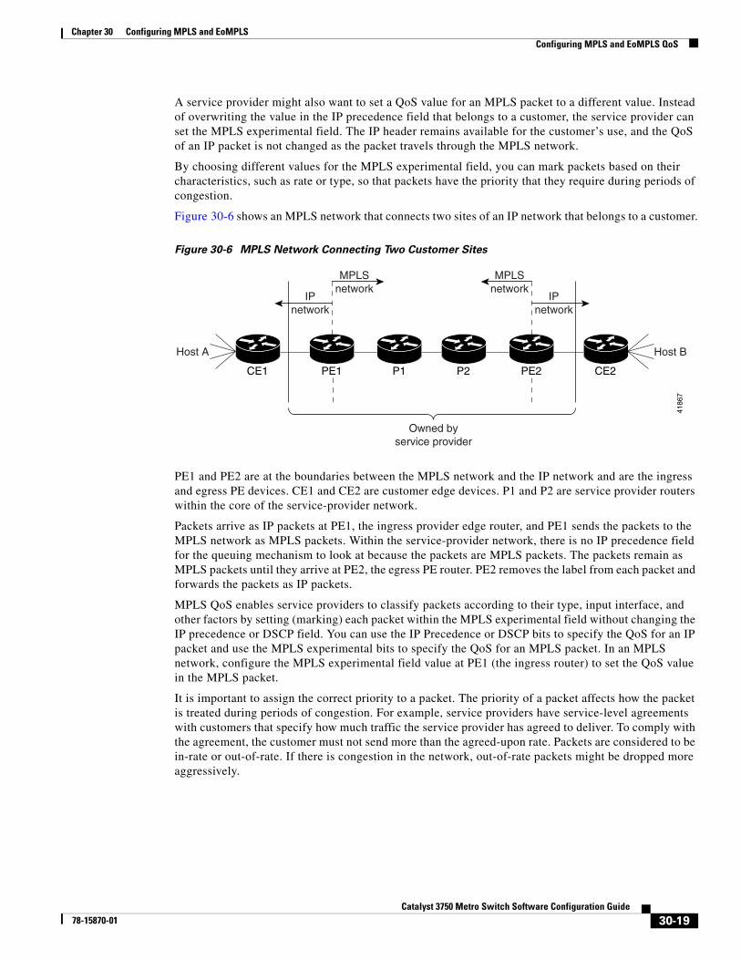
Figure 30-6 shows an MPLS network that connects two sites of an IP network that belongs to a customer.
Figure 30-6 MPLS Network Connecting Two Customer Sites
PE1 and PE2 are at the boundaries between the MPLS network and the IP network and are the ingress and egress PE devices. CE1 and CE2 are customer edge devices. P1 and P2 are service provider routers within the core of the service-provider network.
Packets arrive as IP packets at PE1, the ingress provider edge router, and PE1 sends the packets to the MPLS network as MPLS packets. Within the service-provider network, there is no IP precedence field for the queuing mechanism to look at because the packets are MPLS packets. The packets remain as MPLS packets until they arrive at PE2, the egress PE router. PE2 removes the label from each packet and forwards the packets as IP packets.
MPLS QoS enables service providers to classify packets according to their type, input interface, and other factors by setting (marking) each packet within the MPLS experimental field without changing the IP precedence or DSCP field. You can use the IP Precedence or DSCP bits to specify the QoS for an IP packet and use the MPLS experimental bits to specify the QoS for an MPLS packet. In an MPLS network, configure the MPLS experimental field value at PE1 (the ingress router) to set the QoS value in the MPLS packet.
It is important to assign the correct priority to a packet. The priority of a packet affects how the packet is treated during periods of congestion. For example, service providers have service-level agreements with customers that specify how much traffic the service provider has agreed to deliver. To comply with the agreement, the customer must not send more than the agreed-upon rate. Packets are considered to be in-rate or out-of-rate. If there is congestion in the network, out-of-rate packets might be dropped more aggressively.
CE1
4186
7
PE1 P1 P2 PE2 CE2
IPnetwork
MPLSnetwork
IPnetwork
MPLSnetwork
Host A Host B
Owned byservice provider
30-19Catalyst 3750 Metro Switch Software Configuration Guide
78-15870-01
Chapter 30 Configuring MPLS and EoMPLSConfiguring MPLS and EoMPLS QoS
Enabling MPLS and EoMPLS QoSThis section describes how to configure MPLS QoS on the ingress PE router. It includes these topics:
• Default MPLS and EoMPLS QoS Configuration, page 30-20
• Setting the Priority of Packets with Experimental Bits, page 30-20
For more information about QoS, see Chapter 26, “Configuring QoS.”
Default MPLS and EoMPLS QoS Configuration
QoS is disabled. Packets are not modified, and the CoS, DSCP, and IP precedence values in the packet are not changed. Traffic is switched in pass-through mode (packets are switched without any rewrites and classified as best effort without any policing).
The default behavior for the VLAN-tunneled EoMPLS or VFI packets is to relay the 802.1p bits into the EXP bits. The default value for the EXP bits for port-tunneled EoMPLS or VFI is zero.
When QoS is enabled with the mls qos global configuration command and all other QoS settings are at their defaults, traffic is classified as best effort (the DSCP value is set to 0) without any policing. No policy maps are configured.
Note For MPLS and EoMPLS QoS, you can match only Layer 3 parameters (IP or DCSP values), not Layer 2 (CoS values).
Setting the Priority of Packets with Experimental Bits
MPLS and EoMPLS provide QoS on the ingress router by using 3 experimental bits in a label to determine the priority of packets. To support QoS between LERs, set the experimental bits in both the VC and tunnel labels. If you do not assign values to the experimental bits, the priority bits in the 802.1Q header tag control information field are written into the experimental bit fields.
The process includes these steps on the ingress router:
• Configure a class map to classify IP packets according to their DSCP or IP precedence classification.
Note The switch supports only DSCP and IP precedence classification for MPLS and EoMPLS.
• Configure a policy map to mark MPLS packets (write their classification into the MPLS experimental field).
• Configure the input interface to attach the service policy.
Beginning in privileged EXEC mode, follow these steps to set the experimental bits for EoMPLS or MPLS QoS:
Command Purpose
Step 1 configure terminal Enter global configuration mode.
Step 2 mls qos Enable QoS globally.
QoS runs from the default settings described in Chapter 26, “Configuring QoS.”
30-20Catalyst 3750 Metro Switch Software Configuration Guide
78-15870-01
Chapter 30 Configuring MPLS and EoMPLSConfiguring MPLS and EoMPLS QoS
To delete an existing policy map, use the no policy-map policy-map-name global configuration command. To delete an existing class, use the no class class-name policy-map configuration command.
This example shows how to use class and policy maps to configure different experimental bit settings for DSCP and IP precedence for MPLS QoS.
Switch(config)# class-map match-all gold-classSwitch(config-cmap)# match ip dscp 1Switch(config-cmap)# exitSwitch(config)# class-map match-all silver-classSwitch(config-cmap)# match ip precedence 2Switch(config-cmap)# exit
Switch(config)# policy-map out-policySwitch(config-pmap)# class gold-classSwitch(config-pmap-c)# set mpls experimental 5Switch(config-pmap-c)# exitSwitch(config-pmap)# class silver-classSwitch(config-pmap-c)# set mpls experimental 4Switch(config-pmap-c)# exit
Step 3 class-map class-map-name Specify the name of the traffic class, and enter class-map configuration mode.
Step 4 match {ip dscp dscp-list | ip precedence ip-precedence-list}
Specify the matching criteria for 802.1Q packets.
• ip dscp dscp-list—list of up to eight IP DSCP values to match against incoming packets. The range is 0 to 63.
• ip precedence ip-precedence-list—list of up to eight IP-precedence values to match against incoming packets. Separate each value with a space. The range is 0 to 7.
Note The switch does not support the cos and vlan keywords for MPLS and EoMPLS.
Step 5 exit Return to global configuration mode.
Step 6 policy-map policy-map-name Specify the name of the traffic policy to configure, and enter policy-map configuration mode.
Step 7 class class-name Specify the name of the predefined traffic class configured with the class-map command, and enter policy-map class configuration mode.
Step 8 set mpls experimental exp-number Specify the value to which the MPLS bits are set if the packets match the specified policy map. The range is 0 to 7.
Step 9 exit Return to policy-map configuration mode.
Step 10 exit Return to global configuration mode.
Step 11 interface interface-id Enter the interface ID, and enter interface configuration mode. The interface should be the ES egress port of the ingress router.
Step 12 service-policy output policy-map-name Attach the specified policy map to the output interface.
Step 13 end Return to privileged EXEC mode.
Step 14 show policy-map [policy-map-name [class class-map-name]]
show policy-map interface interface-id
Verify the configuration.
Step 15 copy running-config startup-config (Optional) Save your entries in the configuration file.
Command Purpose
30-21Catalyst 3750 Metro Switch Software Configuration Guide
78-15870-01
Chapter 30 Configuring MPLS and EoMPLSMonitoring and Maintaining MPLS and EoMPLS
Switch(config)# interface gigabitethernet1/1/1Switch(config-if)# service-policy output out-policySwitch(config-if)# end
Monitoring and Maintaining MPLS and EoMPLSTo clear MPLS counters or display MPLS and EoMPLS information, use the privileged EXEC commands in Table 30-1.
Table 30-1 Commands for Displaying MPLS and EoMPLS Information
Command Purpose
clear mpls counters Clear MPLS forwarding counters.
show mpls forwarding-table Display the contents of the MPLS label forwarding information base (LFIB).
show mpls interfaces Display information about interfaces that have been configured for label switching.
show mpls ip binding Display specified information about label bindings learned by LDP.
show mpls l2transport vc [detail] [summary] Display detailed or summary information about the EoMPLS virtual connections that have been enabled to route Layer 2 packets on a provider-edge device.
show mpls l2transport vc [vc-id] [vc-id-min - vc-id-max] Display information about the specified VC or range of VCs. The range is from 1 to 4294967295.
show mpls label range Display the range of local labels available for use on packet interfaces.
show mpls ldp bindings Display the contents of the label information base (LIB).
show mpls ldp discovery Display the status of the LDP discovery process.
show mpls ldp neighbor Display the status of LDP sessions.
show mpls ldp parameters Display current LDP parameters.
show mpls prefix-map Show the prefix map used to assign a QoS map to network prefixes that match a standard IP access list.
show mpls ldp backoff Display information about the configured session setup backoff parameters and any potential LDP peers with which session setup attempts are being throttled.
30-22Catalyst 3750 Metro Switch Software Configuration Guide
78-15870-01