Embed Size (px)
Citation preview
WC-157Cisco IOS Wide-Area Networking Configuration Guide
Configuring Frame Relay
This chapter describes the tasks for configuring Frame Relay on a router or access server. For further general information about Frame Relay, see the chapter “Wide-Area Networking Overview” at the beginning of this book.
For a complete description of the Frame Relay commands mentioned in this chapter, refer to the chapter “Frame Relay Commands” in the Cisco IOS Wide-Area Networking Command Reference. To locate documentation of other commands that appear in this chapter, use the command reference master index or search online.
To identify the hardware platform or software image information associated with a feature, use the Feature Navigator on Cisco.com to search for information about the feature or refer to the software release notes for a specific release. For more information, see the section “Identifying Supported Platforms” in the chapter “Using Cisco IOS Software.”
For information on the following related topics, see the corresponding chapters in other Cisco publications:
Task Resource
Sending DDR traffic over Frame Relay “Configuring Legacy DDR Spokes” and “Configuring Legacy DDR Hubs” chapters in the “Dial-on-Demand Routing Configuration” part in the Cisco IOS Dial Technologies Configuration Guide
Installing software on a new router or access server by downloading from a central server over an interface that supports Frame Relay
“Loading and Maintaining System Images” chapter in the Cisco IOS Configuration Fundamentals Configuration Guide
Using AutoInstall over Frame Relay “Using Autoinstall and Setup” chapter in the Cisco IOS Configuration Fundamentals Configuration Guide
Configuring transparent bridging between devices over a Frame Relay network
“Configuring Transparent Bridging” chapter in the Cisco IOS Bridging and IBM Networking Configuration Guide
Configuring source-route bridging between SNA devices over a Frame Relay network
“Configuring Source-Route Bridging” chapter in the Cisco IOS Bridging and IBM Networking Configuration Guide
Configuring serial tunnel (STUN) and block serial tunnel encapsulation between devices over a Frame Relay network
“Configuring Serial Tunnel and Block Serial Tunnel” chapter in the Cisco IOS Bridging and IBM Networking Configuration Guide
Configuring Frame RelayCisco Frame Relay MIB
WC-158Cisco IOS Wide-Area Networking Configuration Guide
Cisco Frame Relay MIB The Cisco Frame Relay MIB adds extensions to the standard Frame Relay MIB (RFC 1315). It provides additional link-level and virtual circuit (VC)-level information and statistics that are mostly specific to Cisco Frame Relay implementation. This MIB provides SNMP network management access to most of the information covered by the show frame-relay commands such as, show frame-relay lmi, show frame-relay pvc, show frame-relay map, and show frame-relay svc.
Frame Relay Hardware Configurations You can create Frame Relay connections using one of the following hardware configurations:
• Routers and access servers connected directly to the Frame Relay switch
• Routers and access servers connected directly to a channel service unit/digital service unit (CSU/DSU), which then connects to a remote Frame Relay switch
Note Routers can connect to Frame Relay networks either by direct connection to a Frame Relay switch or through CSU/DSUs. However, a single router interface configured for Frame Relay can be configured for only one of these methods.
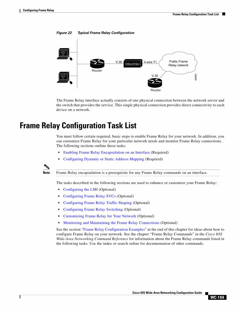
The CSU/DSU converts V.35 or RS-449 signals to the properly coded T1 transmission signal for successful reception by the Frame Relay network. Figure 22 illustrates the connections among the components.
Configuring access between SNA devices over a Frame Relay network
“Configuring SNA Frame Relay Access Support” chapter in the Cisco IOS Bridging and IBM Networking Configuration Guide
Configuring Voice over Frame Relay Using FRF.11 and FRF.12
“Configuring Voice over Frame Relay” chapter in the Cisco IOS Voice, Video, and Fax Configuration Guide
Configuring low latency queueing, PVC interface priority queueing, and link fragmentation and interleaving using multilink PPP for Frame Relay
Cisco IOS Quality of Service Solutions Configuration Guide
Task Resource
Configuring Frame RelayFrame Relay Configuration Task List
WC-159Cisco IOS Wide-Area Networking Configuration Guide
Figure 22 Typical Frame Relay Configuration
The Frame Relay interface actually consists of one physical connection between the network server and the switch that provides the service. This single physical connection provides direct connectivity to each device on a network.
Frame Relay Configuration Task ListYou must follow certain required, basic steps to enable Frame Relay for your network. In addition, you can customize Frame Relay for your particular network needs and monitor Frame Relay connections. The following sections outline these tasks:
• Enabling Frame Relay Encapsulation on an Interface (Required)
• Configuring Dynamic or Static Address Mapping (Required)
Note Frame Relay encapsulation is a prerequisite for any Frame Relay commands on an interface.
The tasks described in the following sections are used to enhance or customize your Frame Relay:
• Configuring the LMI (Optional)
• Configuring Frame Relay SVCs (Optional)
• Configuring Frame Relay Traffic Shaping (Optional)
• Configuring Frame Relay Switching (Optional)
• Customizing Frame Relay for Your Network (Optional)
• Monitoring and Maintaining the Frame Relay Connections (Optional)
See the section “Frame Relay Configuration Examples” at the end of this chapter for ideas about how to configure Frame Relay on your network. See the chapter “Frame Relay Commands” in the Cisco IOS Wide-Area Networking Command Reference for information about the Frame Relay commands listed in the following tasks. Use the index or search online for documentation of other commands.
Router
DSU/CSUV.35
6286
3
Public FrameRelay network
4-wire T1
Router
V.35
Configuring Frame RelayEnabling Frame Relay Encapsulation on an Interface
WC-160Cisco IOS Wide-Area Networking Configuration Guide
Enabling Frame Relay Encapsulation on an InterfaceTo enable Frame Relay encapsulation on the interface level, use the following commands beginning in global configuration mode:
Frame Relay supports encapsulation of all supported protocols in conformance with RFC 1490, allowing interoperability among multiple vendors. Use the Internet Engineering Task Force (IETF) form of Frame Relay encapsulation if your router or access server is connected to another vendor’s equipment across a Frame Relay network. IETF encapsulation is supported either at the interface level or on a per-VC basis.
Shut down the interface prior to changing encapsulation types. Although shutting down the interface is not required, it ensures that the interface is reset for the new encapsulation.
For an example of enabling Frame Relay encapsulation on an interface, see the section “IETF Encapsulation Examples” later in this chapter.
Configuring Dynamic or Static Address MappingDynamic address mapping uses Frame Relay Inverse ARP to request the next-hop protocol address for a specific connection, given its known DLCI. Responses to Inverse ARP requests are entered in an address-to-DLCI mapping table on the router or access server; the table is then used to supply the next-hop protocol address or the DLCI for outgoing traffic.
Inverse ARP is enabled by default for all protocols it supports, but can be disabled for specific protocol-DLCI pairs. As a result, you can use dynamic mapping for some protocols and static mapping for other protocols on the same DLCI. You can explicitly disable Inverse ARP for a protocol-DLCI pair if you know that the protocol is not supported on the other end of the connection. See the section “Disabling or Reenabling Frame Relay Inverse ARP” later in this chapter for more information.
See the following sections for further details on configuring dynamic or static address mapping:
• Configuring Dynamic Address Mapping
• Configuring Static Address Mapping
Configuring Dynamic Address MappingInverse ARP is enabled by default for all protocols enabled on the physical interface. Packets are not sent out for protocols that are not enabled on the interface.
Because Inverse ARP is enabled by default, no additional command is required to configure dynamic mapping on an interface.
Command Purpose
Step 1 Router(config)# interface type number
Specifies the interface, and enters interface configuration mode.
Step 2 Router(config-if)# encapsulation frame-relay [ietf]
Enables and specifies the Frame Relay encapsulation method.
Configuring Frame RelayConfiguring the LMI
WC-161Cisco IOS Wide-Area Networking Configuration Guide
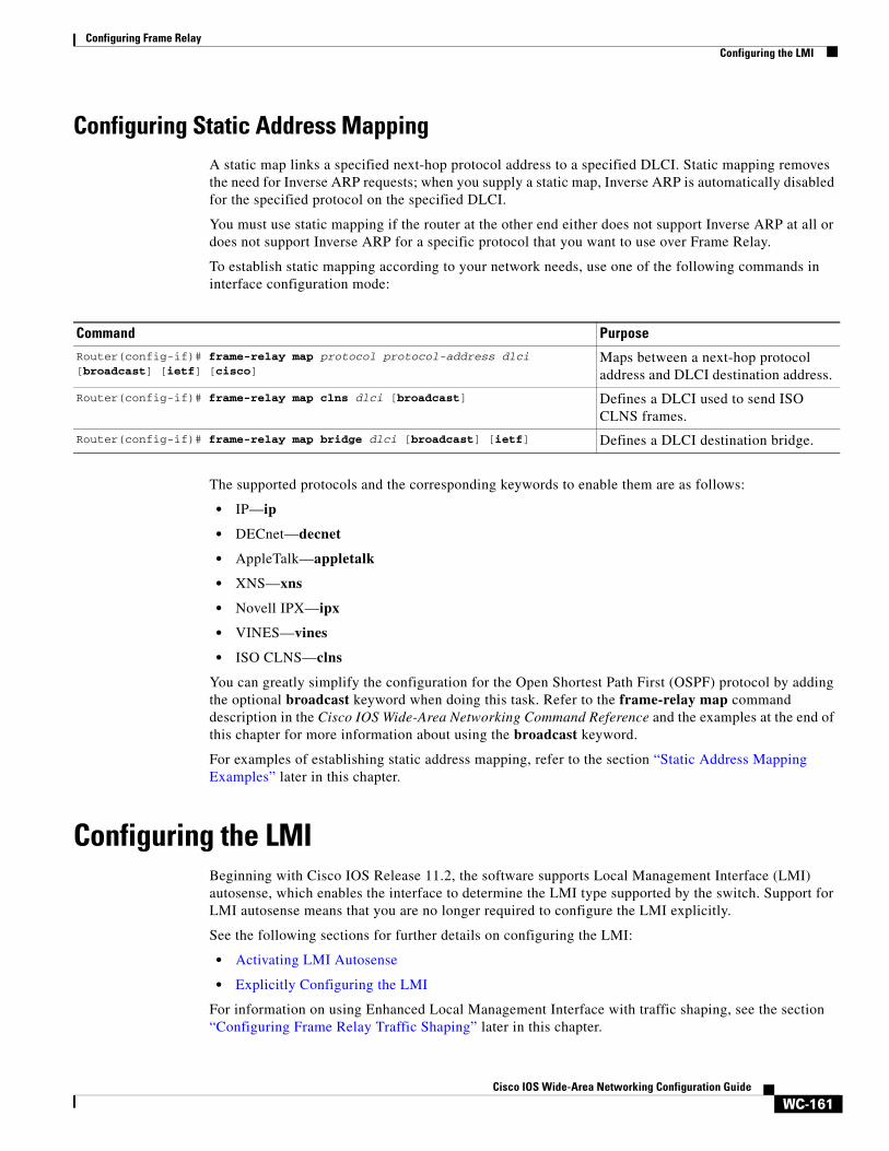
Configuring Static Address MappingA static map links a specified next-hop protocol address to a specified DLCI. Static mapping removes the need for Inverse ARP requests; when you supply a static map, Inverse ARP is automatically disabled for the specified protocol on the specified DLCI.
You must use static mapping if the router at the other end either does not support Inverse ARP at all or does not support Inverse ARP for a specific protocol that you want to use over Frame Relay.
To establish static mapping according to your network needs, use one of the following commands in interface configuration mode:
The supported protocols and the corresponding keywords to enable them are as follows:
• IP—ip
• DECnet—decnet
• AppleTalk—appletalk
• XNS—xns
• Novell IPX—ipx
• VINES—vines
• ISO CLNS—clns
You can greatly simplify the configuration for the Open Shortest Path First (OSPF) protocol by adding the optional broadcast keyword when doing this task. Refer to the frame-relay map command description in the Cisco IOS Wide-Area Networking Command Reference and the examples at the end of this chapter for more information about using the broadcast keyword.
For examples of establishing static address mapping, refer to the section “Static Address Mapping Examples” later in this chapter.
Configuring the LMI Beginning with Cisco IOS Release 11.2, the software supports Local Management Interface (LMI) autosense, which enables the interface to determine the LMI type supported by the switch. Support for LMI autosense means that you are no longer required to configure the LMI explicitly.
See the following sections for further details on configuring the LMI:
• Activating LMI Autosense
• Explicitly Configuring the LMI
For information on using Enhanced Local Management Interface with traffic shaping, see the section “Configuring Frame Relay Traffic Shaping” later in this chapter.
Command PurposeRouter(config-if)# frame-relay map protocol protocol-address dlci [broadcast] [ietf] [cisco]
Maps between a next-hop protocol address and DLCI destination address.
Router(config-if)# frame-relay map clns dlci [broadcast] Defines a DLCI used to send ISO CLNS frames.
Router(config-if)# frame-relay map bridge dlci [broadcast] [ietf] Defines a DLCI destination bridge.
Configuring Frame RelayConfiguring the LMI
WC-162Cisco IOS Wide-Area Networking Configuration Guide
For an example of configuring the LMI, see the section “Pure Frame Relay DCE Example” later in this chapter.
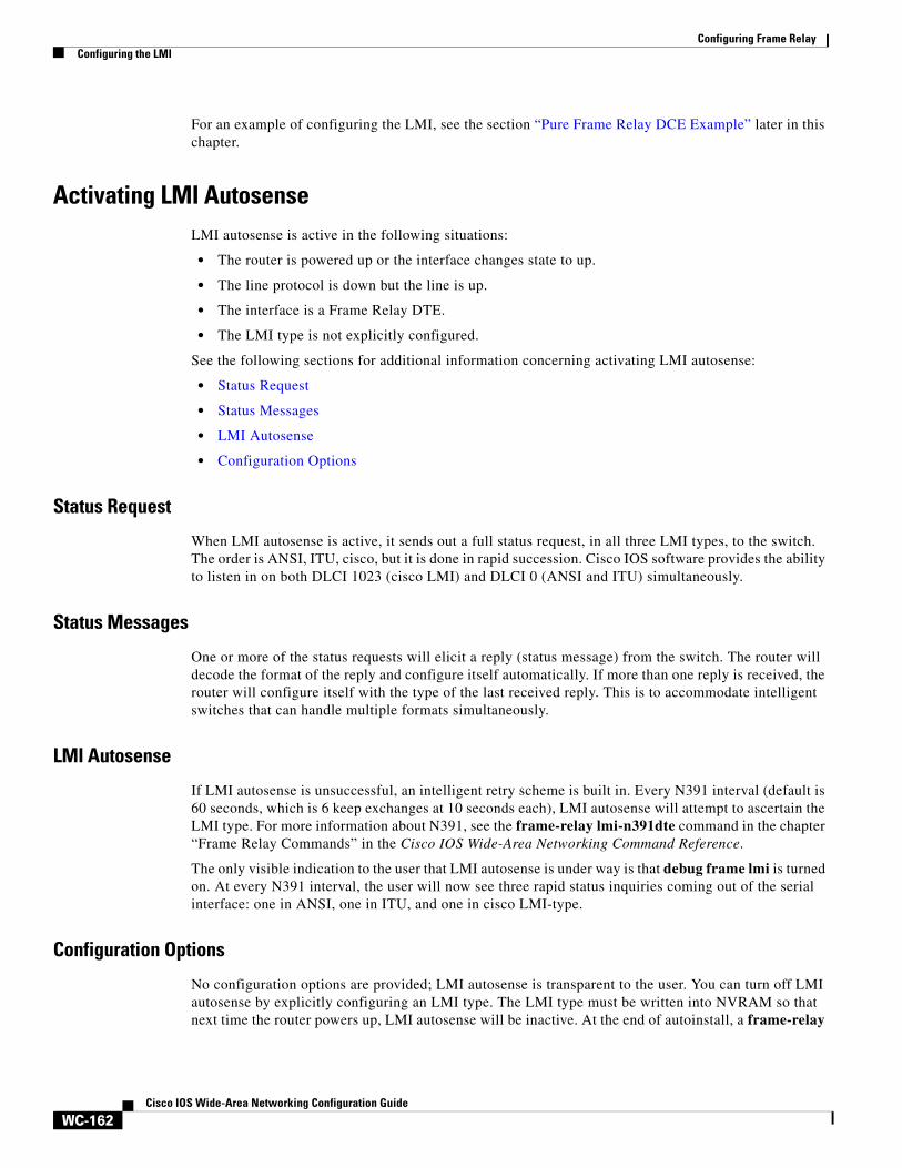
Activating LMI AutosenseLMI autosense is active in the following situations:
• The router is powered up or the interface changes state to up.
• The line protocol is down but the line is up.
• The interface is a Frame Relay DTE.
• The LMI type is not explicitly configured.
See the following sections for additional information concerning activating LMI autosense:
• Status Request
• Status Messages
• LMI Autosense
• Configuration Options
Status Request
When LMI autosense is active, it sends out a full status request, in all three LMI types, to the switch. The order is ANSI, ITU, cisco, but it is done in rapid succession. Cisco IOS software provides the ability to listen in on both DLCI 1023 (cisco LMI) and DLCI 0 (ANSI and ITU) simultaneously.
Status Messages
One or more of the status requests will elicit a reply (status message) from the switch. The router will decode the format of the reply and configure itself automatically. If more than one reply is received, the router will configure itself with the type of the last received reply. This is to accommodate intelligent switches that can handle multiple formats simultaneously.
LMI Autosense
If LMI autosense is unsuccessful, an intelligent retry scheme is built in. Every N391 interval (default is 60 seconds, which is 6 keep exchanges at 10 seconds each), LMI autosense will attempt to ascertain the LMI type. For more information about N391, see the frame-relay lmi-n391dte command in the chapter “Frame Relay Commands” in the Cisco IOS Wide-Area Networking Command Reference.
The only visible indication to the user that LMI autosense is under way is that debug frame lmi is turned on. At every N391 interval, the user will now see three rapid status inquiries coming out of the serial interface: one in ANSI, one in ITU, and one in cisco LMI-type.
Configuration Options
No configuration options are provided; LMI autosense is transparent to the user. You can turn off LMI autosense by explicitly configuring an LMI type. The LMI type must be written into NVRAM so that next time the router powers up, LMI autosense will be inactive. At the end of autoinstall, a frame-relay
Configuring Frame RelayConfiguring the LMI
WC-163Cisco IOS Wide-Area Networking Configuration Guide
lmi-type xxx statement is included within the interface configuration. This configuration is not automatically written to NVRAM; you must explicitly write the configuration to NVRAM by using the copy system:running-config or copy nvram:startup-config command.
Explicitly Configuring the LMI Frame Relay software supports the industry-accepted standards for addressing the LMI, including the Cisco specification. If you want to configure the LMI and thus deactivate LMI autosense, perform the tasks in the following sections:
• Setting the LMI Type (Required)
• Setting the LMI Keepalive Interval (Required)
• Setting the LMI Polling and Timer Intervals (Optional)
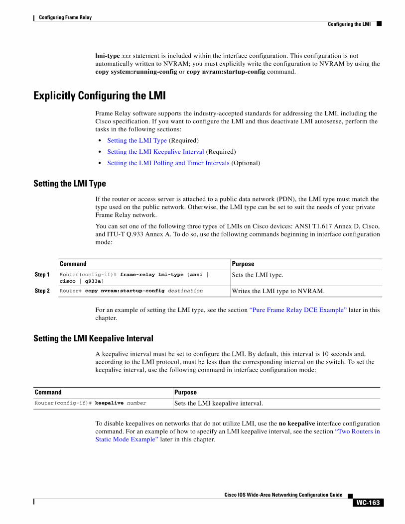
Setting the LMI Type
If the router or access server is attached to a public data network (PDN), the LMI type must match the type used on the public network. Otherwise, the LMI type can be set to suit the needs of your private Frame Relay network.
You can set one of the following three types of LMIs on Cisco devices: ANSI T1.617 Annex D, Cisco, and ITU-T Q.933 Annex A. To do so, use the following commands beginning in interface configuration mode:
For an example of setting the LMI type, see the section “Pure Frame Relay DCE Example” later in this chapter.
Setting the LMI Keepalive Interval
A keepalive interval must be set to configure the LMI. By default, this interval is 10 seconds and, according to the LMI protocol, must be less than the corresponding interval on the switch. To set the keepalive interval, use the following command in interface configuration mode:
To disable keepalives on networks that do not utilize LMI, use the no keepalive interface configuration command. For an example of how to specify an LMI keepalive interval, see the section “Two Routers in Static Mode Example” later in this chapter.
Command Purpose
Step 1 Router(config-if)# frame-relay lmi-type {ansi | cisco | q933a}
Sets the LMI type.
Step 2 Router# copy nvram:startup-config destination Writes the LMI type to NVRAM.
Command Purpose
Router(config-if)# keepalive number Sets the LMI keepalive interval.
Configuring Frame RelayConfiguring Frame Relay SVCs
WC-164Cisco IOS Wide-Area Networking Configuration Guide
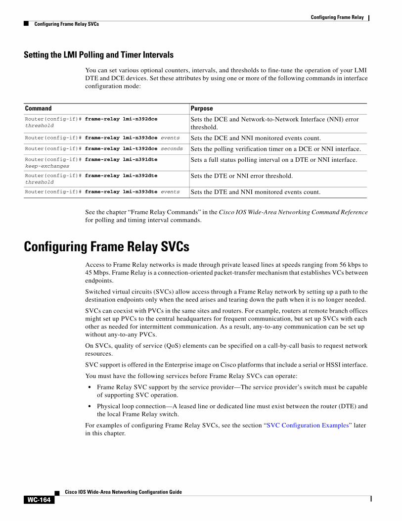
Setting the LMI Polling and Timer Intervals
You can set various optional counters, intervals, and thresholds to fine-tune the operation of your LMI DTE and DCE devices. Set these attributes by using one or more of the following commands in interface configuration mode:
See the chapter “Frame Relay Commands” in the Cisco IOS Wide-Area Networking Command Reference for polling and timing interval commands.
Configuring Frame Relay SVCs Access to Frame Relay networks is made through private leased lines at speeds ranging from 56 kbps to 45 Mbps. Frame Relay is a connection-oriented packet-transfer mechanism that establishes VCs between endpoints.
Switched virtual circuits (SVCs) allow access through a Frame Relay network by setting up a path to the destination endpoints only when the need arises and tearing down the path when it is no longer needed.
SVCs can coexist with PVCs in the same sites and routers. For example, routers at remote branch offices might set up PVCs to the central headquarters for frequent communication, but set up SVCs with each other as needed for intermittent communication. As a result, any-to-any communication can be set up without any-to-any PVCs.
On SVCs, quality of service (QoS) elements can be specified on a call-by-call basis to request network resources.
SVC support is offered in the Enterprise image on Cisco platforms that include a serial or HSSI interface.
You must have the following services before Frame Relay SVCs can operate:
• Frame Relay SVC support by the service provider—The service provider’s switch must be capable of supporting SVC operation.
• Physical loop connection—A leased line or dedicated line must exist between the router (DTE) and the local Frame Relay switch.
For examples of configuring Frame Relay SVCs, see the section “SVC Configuration Examples” later in this chapter.
Command PurposeRouter(config-if)# frame-relay lmi-n392dce threshold
Sets the DCE and Network-to-Network Interface (NNI) error threshold.
Router(config-if)# frame-relay lmi-n393dce events Sets the DCE and NNI monitored events count.
Router(config-if)# frame-relay lmi-t392dce seconds Sets the polling verification timer on a DCE or NNI interface.
Router(config-if)# frame-relay lmi-n391dte keep-exchanges
Sets a full status polling interval on a DTE or NNI interface.
Router(config-if)# frame-relay lmi-n392dte threshold
Sets the DTE or NNI error threshold.
Router(config-if)# frame-relay lmi-n393dte events Sets the DTE and NNI monitored events count.
Configuring Frame RelayConfiguring Frame Relay SVCs
WC-165Cisco IOS Wide-Area Networking Configuration Guide
Operating SVCsSVC operation requires that the Data Link layer (Layer 2) be set up, running ITU-T Q.922 Link Access Procedures to Frame mode bearer services (LAPF), prior to signalling for an SVC. Layer 2 sets itself up as soon as SVC support is enabled on the interface, if both the line and the line protocol are up. When the SVCs are configured and demand for a path occurs, the Q.933 signalling sequence is initiated. Once the SVC is set up, data transfer begins.
Q.922 provides a reliable link layer for Q.933 operation. All Q.933 call control information is transmitted over DLCI 0; this DLCI is also used for the management protocols specified in ANSI T1.617 Annex D or Q.933 Annex A.
You must enable SVC operation at the interface level. Once it is enabled at the interface level, it is enabled on any subinterfaces on that interface. One signalling channel, DLCI 0, is set up for the interface, and all SVCs are controlled from the physical interface.
Enabling Frame Relay SVC ServiceTo enable Frame Relay SVC service and set up SVCs, perform the tasks in the following sections. The subinterface tasks are not required, but offer additional flexibility for SVC configuration and operation. The LAPF tasks are not required and not recommended unless you understand thoroughly the impacts on your network.
• Configuring SVCs on a Physical Interface (Required)
• Configuring SVCs on a Subinterface (Optional)
• Configuring a Map Class (Required)
• Configuring a Map Group with E.164 or X.121 Addresses (Required)
• Associating the Map Class with Static Protocol Address Maps (Required)
• Configuring LAPF Parameters (Optional)
For examples of configuring Frame Relay SVCs, see the section “SVC Configuration Examples” later in this chapter.
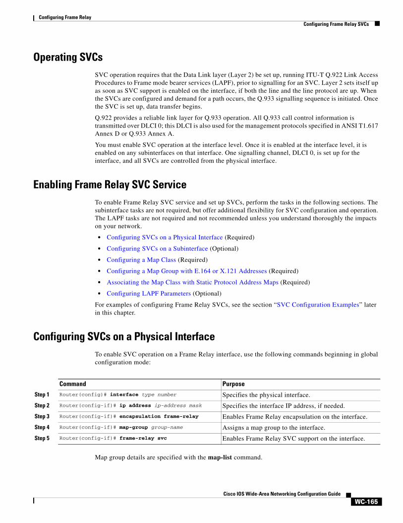
Configuring SVCs on a Physical Interface To enable SVC operation on a Frame Relay interface, use the following commands beginning in global configuration mode:
Map group details are specified with the map-list command.
Command Purpose
Step 1 Router(config)# interface type number Specifies the physical interface.
Step 2 Router(config-if)# ip address ip-address mask Specifies the interface IP address, if needed.
Step 3 Router(config-if)# encapsulation frame-relay Enables Frame Relay encapsulation on the interface.
Step 4 Router(config-if)# map-group group-name Assigns a map group to the interface.
Step 5 Router(config-if)# frame-relay svc Enables Frame Relay SVC support on the interface.
Configuring Frame RelayConfiguring Frame Relay SVCs
WC-166Cisco IOS Wide-Area Networking Configuration Guide
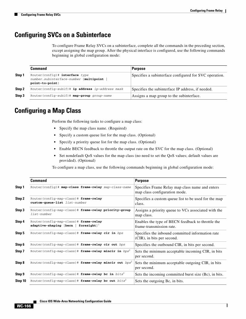
Configuring SVCs on a Subinterface To configure Frame Relay SVCs on a subinterface, complete all the commands in the preceding section, except assigning the map group. After the physical interface is configured, use the following commands beginning in global configuration mode:
Configuring a Map Class Perform the following tasks to configure a map class:
• Specify the map class name. (Required)
• Specify a custom queue list for the map class. (Optional)
• Specify a priority queue list for the map class. (Optional)
• Enable BECN feedback to throttle the output rate on the SVC for the map class. (Optional)
• Set nondefault QoS values for the map class (no need to set the QoS values; default values are provided). (Optional)
To configure a map class, use the following commands beginning in global configuration mode:
Command Purpose
Step 1 Router(config)# interface type number.subinterface-number {multipoint | point-to-point}
Specifies a subinterface configured for SVC operation.
Step 2 Router(config-subif)# ip address ip-address mask Specifies the subinterface IP address, if needed.
Step 3 Router(config-subif)# map-group group-name Assigns a map group to the subinterface.
Command Purpose
Step 1 Router(config)# map-class frame-relay map-class-name Specifies Frame Relay map class name and enters map class configuration mode.
Step 2 Router(config-map-class)# frame-relay custom-queue-list list-number
Specifies a custom queue list to be used for the map class.
Step 3 Router(config-map-class)# frame-relay priority-group list-number
Assigns a priority queue to VCs associated with the map class.
Step 4 Router(config-map-class)# frame-relay adaptive-shaping [becn | foresight]1
Enables the type of BECN feedback to throttle the frame-transmission rate.
Step 5 Router(config-map-class)# frame-relay cir in bps Specifies the inbound committed information rate (CIR), in bits per second.
Step 6 Router(config-map-class)# frame-relay cir out bps Specifies the outbound CIR, in bits per second.
Step 7 Router(config-map-class)# frame-relay mincir in bps2 Sets the minimum acceptable incoming CIR, in bits per second.
Step 8 Router(config-map-class)# frame-relay mincir out bps2 Sets the minimum acceptable outgoing CIR, in bits per second.
Step 9 Router(config-map-class)# frame-relay bc in bits2 Sets the incoming committed burst size (Bc), in bits.
Step 10 Router(config-map-class)# frame-relay bc out bits2 Sets the outgoing Bc, in bits.
Configuring Frame RelayConfiguring Frame Relay SVCs
WC-167Cisco IOS Wide-Area Networking Configuration Guide
You can define multiple map classes. A map class is associated with a static map, not with the interface or subinterface itself. Because of the flexibility this association allows, you can define different map classes for different destinations.
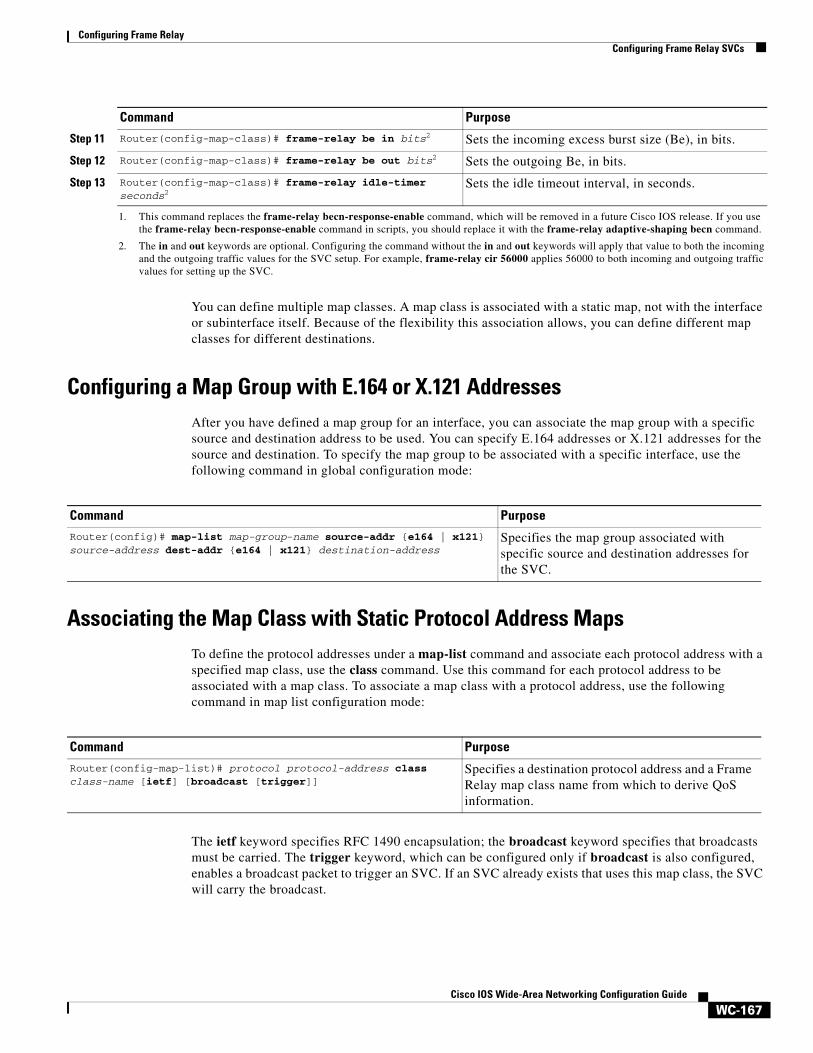
Configuring a Map Group with E.164 or X.121 Addresses After you have defined a map group for an interface, you can associate the map group with a specific source and destination address to be used. You can specify E.164 addresses or X.121 addresses for the source and destination. To specify the map group to be associated with a specific interface, use the following command in global configuration mode:
Associating the Map Class with Static Protocol Address Maps To define the protocol addresses under a map-list command and associate each protocol address with a specified map class, use the class command. Use this command for each protocol address to be associated with a map class. To associate a map class with a protocol address, use the following command in map list configuration mode:
The ietf keyword specifies RFC 1490 encapsulation; the broadcast keyword specifies that broadcasts must be carried. The trigger keyword, which can be configured only if broadcast is also configured, enables a broadcast packet to trigger an SVC. If an SVC already exists that uses this map class, the SVC will carry the broadcast.
Step 11 Router(config-map-class)# frame-relay be in bits2 Sets the incoming excess burst size (Be), in bits.
Step 12 Router(config-map-class)# frame-relay be out bits2 Sets the outgoing Be, in bits.
Step 13 Router(config-map-class)# frame-relay idle-timer seconds2
Sets the idle timeout interval, in seconds.
1. This command replaces the frame-relay becn-response-enable command, which will be removed in a future Cisco IOS release. If you use the frame-relay becn-response-enable command in scripts, you should replace it with the frame-relay adaptive-shaping becn command.
2. The in and out keywords are optional. Configuring the command without the in and out keywords will apply that value to both the incoming and the outgoing traffic values for the SVC setup. For example, frame-relay cir 56000 applies 56000 to both incoming and outgoing traffic values for setting up the SVC.
Command Purpose
Command PurposeRouter(config)# map-list map-group-name source-addr {e164 | x121} source-address dest-addr {e164 | x121} destination-address
Specifies the map group associated with specific source and destination addresses for the SVC.
Command Purpose
Router(config-map-list)# protocol protocol-address class class-name [ietf] [broadcast [trigger]]
Specifies a destination protocol address and a Frame Relay map class name from which to derive QoS information.
Configuring Frame RelayConfiguring Frame Relay Traffic Shaping
WC-168Cisco IOS Wide-Area Networking Configuration Guide
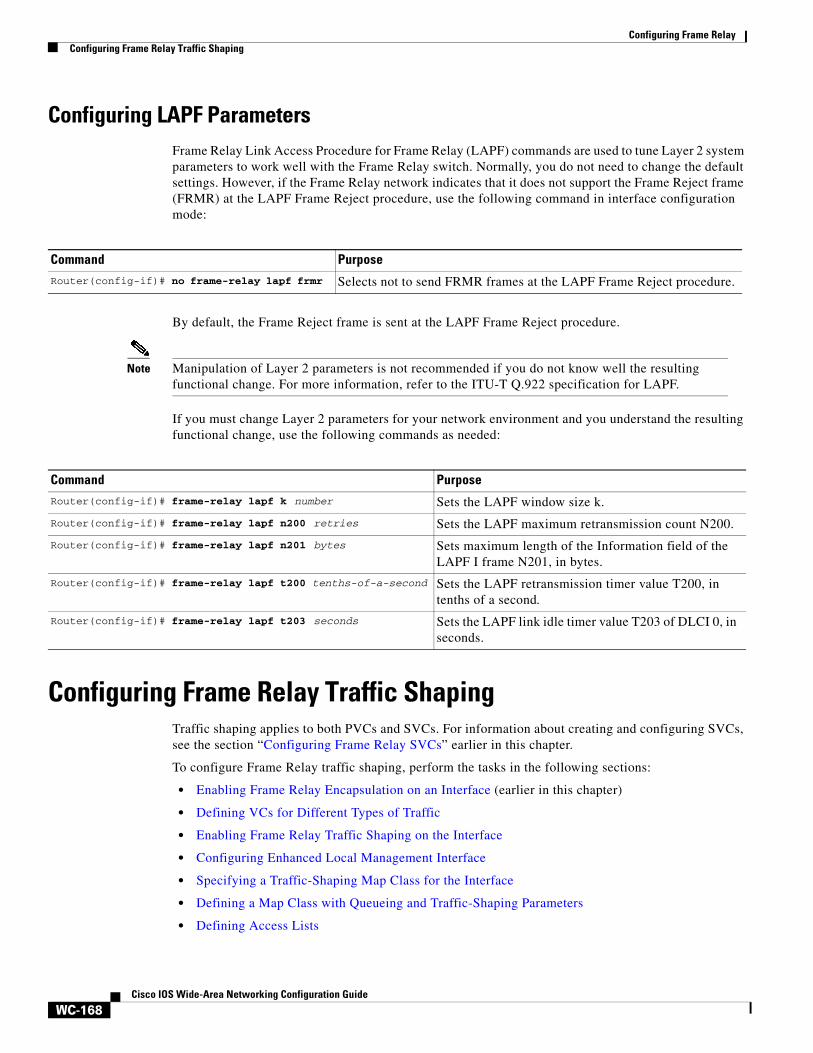
Configuring LAPF ParametersFrame Relay Link Access Procedure for Frame Relay (LAPF) commands are used to tune Layer 2 system parameters to work well with the Frame Relay switch. Normally, you do not need to change the default settings. However, if the Frame Relay network indicates that it does not support the Frame Reject frame (FRMR) at the LAPF Frame Reject procedure, use the following command in interface configuration mode:
By default, the Frame Reject frame is sent at the LAPF Frame Reject procedure.
Note Manipulation of Layer 2 parameters is not recommended if you do not know well the resulting functional change. For more information, refer to the ITU-T Q.922 specification for LAPF.
If you must change Layer 2 parameters for your network environment and you understand the resulting functional change, use the following commands as needed:
Configuring Frame Relay Traffic ShapingTraffic shaping applies to both PVCs and SVCs. For information about creating and configuring SVCs, see the section “Configuring Frame Relay SVCs” earlier in this chapter.
To configure Frame Relay traffic shaping, perform the tasks in the following sections:
• Enabling Frame Relay Encapsulation on an Interface (earlier in this chapter)
• Defining VCs for Different Types of Traffic
• Enabling Frame Relay Traffic Shaping on the Interface
• Configuring Enhanced Local Management Interface
• Specifying a Traffic-Shaping Map Class for the Interface
• Defining a Map Class with Queueing and Traffic-Shaping Parameters
• Defining Access Lists
Command Purpose
Router(config-if)# no frame-relay lapf frmr Selects not to send FRMR frames at the LAPF Frame Reject procedure.
Command Purpose Router(config-if)# frame-relay lapf k number Sets the LAPF window size k.
Router(config-if)# frame-relay lapf n200 retries Sets the LAPF maximum retransmission count N200.
Router(config-if)# frame-relay lapf n201 bytes Sets maximum length of the Information field of the LAPF I frame N201, in bytes.
Router(config-if)# frame-relay lapf t200 tenths-of-a-second Sets the LAPF retransmission timer value T200, in tenths of a second.
Router(config-if)# frame-relay lapf t203 seconds Sets the LAPF link idle timer value T203 of DLCI 0, in seconds.
Configuring Frame RelayConfiguring Frame Relay Traffic Shaping
WC-169Cisco IOS Wide-Area Networking Configuration Guide
• Defining Priority Queue Lists for the Map Class
• Defining Custom Queue Lists for the Map Class
Note Frame Relay traffic shaping is not effective for Layer 2 PVC switching using the frame-relay route command.
For examples of configuring Frame Relay traffic shaping, see the section “Frame Relay Traffic Shaping Examples” later in this chapter.
Defining VCs for Different Types of TrafficBy defining separate VCs for different types of traffic and specifying queueing and an outbound traffic rate for each VC, you can provide guaranteed bandwidth for each type of traffic. By specifying different traffic rates for different VCs over the same line, you can perform virtual time division multiplexing. By throttling outbound traffic from high-speed lines in central offices to lower-speed lines in remote locations, you can ease congestion and data loss in the network; enhanced queueing also prevents congestion-caused data loss.
Enabling Frame Relay Traffic Shaping on the Interface Enabling Frame Relay traffic shaping on an interface enables both traffic shaping and per-VC queueing on all the PVCs and SVCs on the interface. Traffic shaping enables the router to control the circuit’s output rate and react to congestion notification information if also configured.
To enable Frame Relay traffic shaping on the specified interface, use the following command in interface configuration mode:
Note The default committed information rate (CIR) of 56K will apply in the following situations:—When traffic shaping is enabled (by using the frame-relay traffic-shaping command), but a map class is not assigned to the VC—When traffic shaping is enabled (by using the frame-relay traffic-shaping command) and a map class is assigned to the VC, but traffic-shaping parameters have not been defined in the map class
To configure a map class with traffic-shaping and per-VC queueing parameters, see the sections “Specifying a Traffic-Shaping Map Class for the Interface” and “Defining a Map Class with Queueing and Traffic-Shaping Parameters”.
Frame Relay ForeSight
ForeSight is the network traffic control software used in some Cisco switches. The Cisco Frame Relay switch can extend ForeSight messages over a User-to-Network Interface (UNI), passing the backward congestion notification for VCs.
Command Purpose
Router(config-if)# frame-relay traffic-shaping
Enables Frame Relay traffic shaping and per-VC queueing.
Configuring Frame RelayConfiguring Frame Relay Traffic Shaping
WC-170Cisco IOS Wide-Area Networking Configuration Guide
ForeSight allows Cisco Frame Relay routers to process and react to ForeSight messages and adjust VC level traffic shaping in a timely manner.
ForeSight must be configured explicitly on both the Cisco router and the Cisco switch. ForeSight is enabled on the Cisco router when Frame Relay traffic shaping is configured. However, the router’s response to ForeSight is not applied to any VC until the frame-relay adaptive-shaping foresight command is added to the VCs map-class. When ForeSight is enabled on the switch, the switch will periodically send out a ForeSight message based on the time value configured. The time interval can range from 40 to 5000 milliseconds.
When a Cisco router receives a ForeSight message indicating that certain DLCIs are experiencing congestion, the Cisco router reacts by activating its traffic-shaping function to slow down the output rate. The router reacts as it would if it were to detect the congestion by receiving a packet with the backward explicit congestion notification (BECN) bit set.
When ForeSight is enabled, Frame Relay traffic shaping will adapt to ForeSight messages and BECN messages.
For an example of configuring Foresight, see the section “Traffic Shaping with ForeSight Example” later in this chapter.
Frame Relay ForeSight Prerequisites
For router ForeSight to work, the following conditions must exist on the Cisco router:
• Frame Relay traffic shaping must be enabled on the interface.
• The traffic shaping for a circuit is adapted to ForeSight.
The following additional condition must exist on the Cisco switch:
• The UNI connecting to the router is Consolidated Link Layer Management (CLLM) enabled, with the proper time interval specified.
Frame Relay router ForeSight is enabled automatically when you use the frame-relay traffic-shaping command. However, you must issue the map-class frame-relay command and the frame-relay adaptive-shaping foresight command before the router will respond to ForeSight and apply the traffic-shaping effect on a specific interface, subinterface, or VC.
Frame Relay Congestion Notification Methods
The difference between the BECN and ForeSight congestion notification methods is that BECN requires a user packet to be sent in the direction of the congested DLCI to convey the signal. The sending of user packets is not predictable and, therefore, not reliable as a notification mechanism. Rather than waiting for user packets to provide the congestion notification, timed ForeSight messages guarantee that the router receives notification before congestion becomes a problem. Traffic can be slowed down in the direction of the congested DLCI.
Configuring Enhanced Local Management InterfaceEnhanced Local Management Interface (ELMI) allows the router to learn QoS parameters and connectivity information from the Cisco switch and to use this information for traffic shaping, configuration, or management purposes. ELMI simplifies the process of configuring traffic shaping on the router and reduces chances of specifying inconsistent or incorrect values when configuring the router. ELMI works between Cisco routers and Cisco switches (BPX and IGX platforms).
Configuring Frame RelayConfiguring Frame Relay Traffic Shaping
WC-171Cisco IOS Wide-Area Networking Configuration Guide
ELMI QoS Autosense
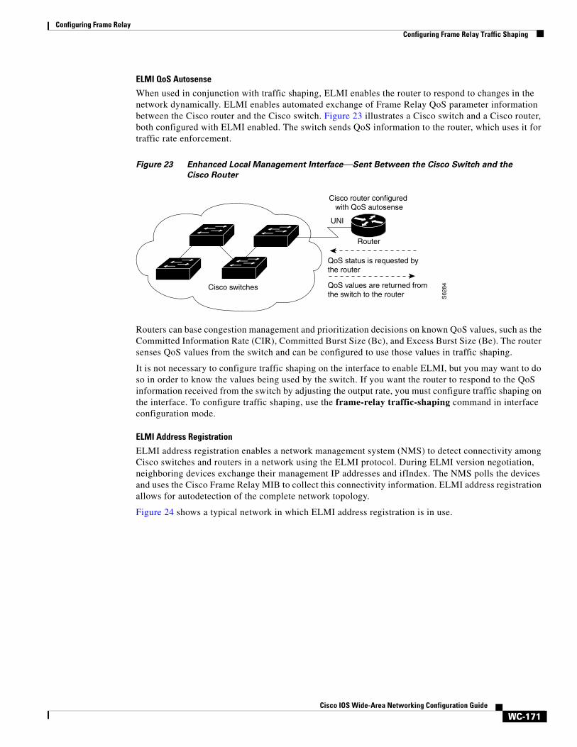
When used in conjunction with traffic shaping, ELMI enables the router to respond to changes in the network dynamically. ELMI enables automated exchange of Frame Relay QoS parameter information between the Cisco router and the Cisco switch. Figure 23 illustrates a Cisco switch and a Cisco router, both configured with ELMI enabled. The switch sends QoS information to the router, which uses it for traffic rate enforcement.
Figure 23 Enhanced Local Management Interface—Sent Between the Cisco Switch and the
Cisco Router
Routers can base congestion management and prioritization decisions on known QoS values, such as the Committed Information Rate (CIR), Committed Burst Size (Bc), and Excess Burst Size (Be). The router senses QoS values from the switch and can be configured to use those values in traffic shaping.
It is not necessary to configure traffic shaping on the interface to enable ELMI, but you may want to do so in order to know the values being used by the switch. If you want the router to respond to the QoS information received from the switch by adjusting the output rate, you must configure traffic shaping on the interface. To configure traffic shaping, use the frame-relay traffic-shaping command in interface configuration mode.
ELMI Address Registration
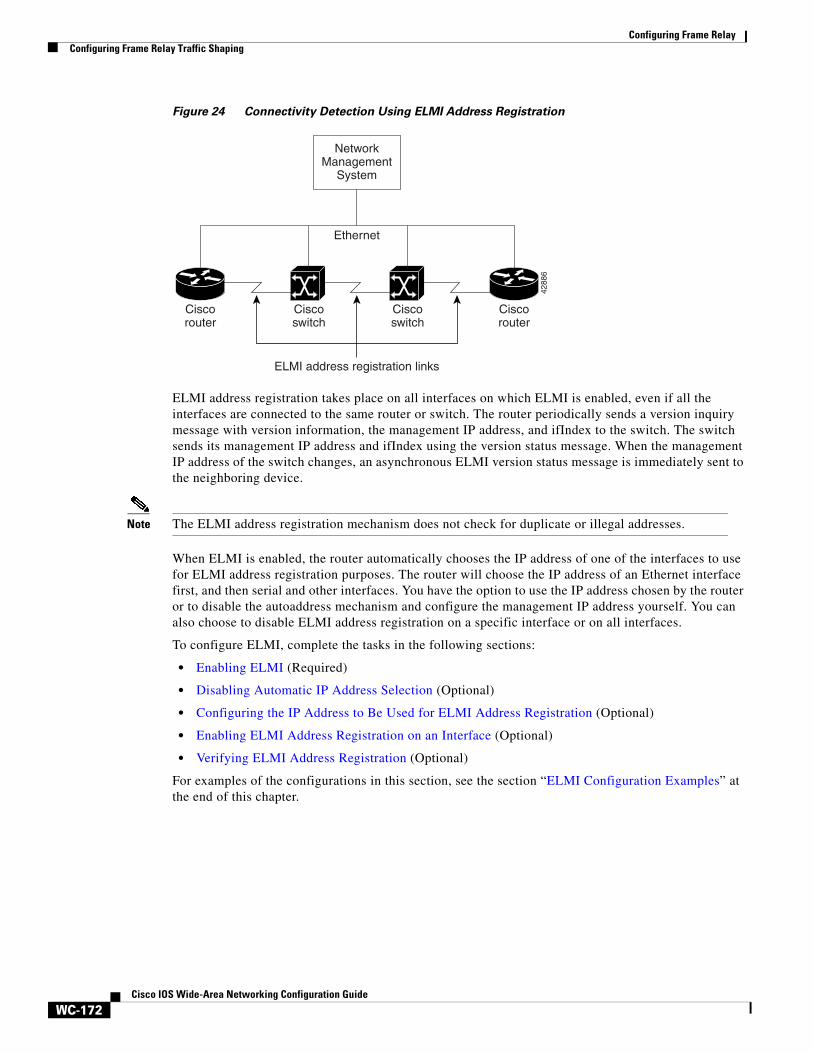
ELMI address registration enables a network management system (NMS) to detect connectivity among Cisco switches and routers in a network using the ELMI protocol. During ELMI version negotiation, neighboring devices exchange their management IP addresses and ifIndex. The NMS polls the devices and uses the Cisco Frame Relay MIB to collect this connectivity information. ELMI address registration allows for autodetection of the complete network topology.
Figure 24 shows a typical network in which ELMI address registration is in use.
QoS status is requested bythe router
QoS values are returned from the switch to the router
UNI
S62
84
Cisco router configured with QoS autosense
Router
Cisco switches
Configuring Frame RelayConfiguring Frame Relay Traffic Shaping
WC-172Cisco IOS Wide-Area Networking Configuration Guide
Figure 24 Connectivity Detection Using ELMI Address Registration
ELMI address registration takes place on all interfaces on which ELMI is enabled, even if all the interfaces are connected to the same router or switch. The router periodically sends a version inquiry message with version information, the management IP address, and ifIndex to the switch. The switch sends its management IP address and ifIndex using the version status message. When the management IP address of the switch changes, an asynchronous ELMI version status message is immediately sent to the neighboring device.
Note The ELMI address registration mechanism does not check for duplicate or illegal addresses.
When ELMI is enabled, the router automatically chooses the IP address of one of the interfaces to use for ELMI address registration purposes. The router will choose the IP address of an Ethernet interface first, and then serial and other interfaces. You have the option to use the IP address chosen by the router or to disable the autoaddress mechanism and configure the management IP address yourself. You can also choose to disable ELMI address registration on a specific interface or on all interfaces.
To configure ELMI, complete the tasks in the following sections:
• Enabling ELMI (Required)
• Disabling Automatic IP Address Selection (Optional)
• Configuring the IP Address to Be Used for ELMI Address Registration (Optional)
• Enabling ELMI Address Registration on an Interface (Optional)
• Verifying ELMI Address Registration (Optional)
For examples of the configurations in this section, see the section “ELMI Configuration Examples” at the end of this chapter.
NetworkManagement
System
Ethernet
Ciscorouter
Ciscoswitch
Ciscoswitch
Ciscorouter
ELMI address registration links
4288
6
Configuring Frame RelayConfiguring Frame Relay Traffic Shaping
WC-173Cisco IOS Wide-Area Networking Configuration Guide
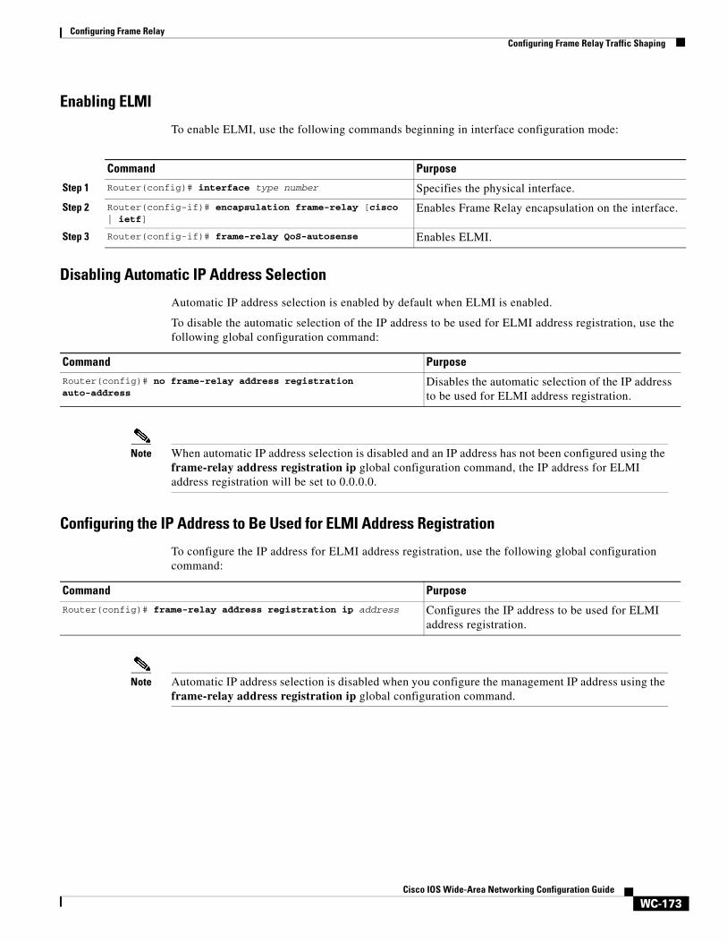
Enabling ELMI
To enable ELMI, use the following commands beginning in interface configuration mode:
Disabling Automatic IP Address Selection
Automatic IP address selection is enabled by default when ELMI is enabled.
To disable the automatic selection of the IP address to be used for ELMI address registration, use the following global configuration command:
Note When automatic IP address selection is disabled and an IP address has not been configured using the frame-relay address registration ip global configuration command, the IP address for ELMI address registration will be set to 0.0.0.0.
Configuring the IP Address to Be Used for ELMI Address Registration
To configure the IP address for ELMI address registration, use the following global configuration command:
Note Automatic IP address selection is disabled when you configure the management IP address using the frame-relay address registration ip global configuration command.
Command Purpose
Step 1 Router(config)# interface type number Specifies the physical interface.
Step 2 Router(config-if)# encapsulation frame-relay [cisco | ietf]
Enables Frame Relay encapsulation on the interface.
Step 3 Router(config-if)# frame-relay QoS-autosense Enables ELMI.
Command Purpose
Router(config)# no frame-relay address registration auto-address
Disables the automatic selection of the IP address to be used for ELMI address registration.
Command Purpose
Router(config)# frame-relay address registration ip address Configures the IP address to be used for ELMI address registration.
Configuring Frame RelayConfiguring Frame Relay Traffic Shaping
WC-174Cisco IOS Wide-Area Networking Configuration Guide
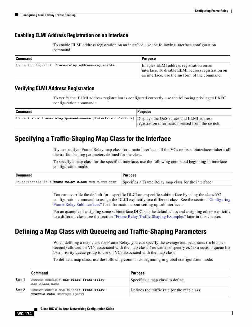
Enabling ELMI Address Registration on an Interface
To enable ELMI address registration on an interface, use the following interface configuration command:
Verifying ELMI Address Registration
To verify that ELMI address registration is configured correctly, use the following privileged EXEC configuration command:
Specifying a Traffic-Shaping Map Class for the InterfaceIf you specify a Frame Relay map class for a main interface, all the VCs on its subinterfaces inherit all the traffic-shaping parameters defined for the class.
To specify a map class for the specified interface, use the following command beginning in interface configuration mode:
You can override the default for a specific DLCI on a specific subinterface by using the class VC configuration command to assign the DLCI explicitly to a different class. See the section “Configuring Frame Relay Subinterfaces” for information about setting up subinterfaces.
For an example of assigning some subinterface DLCIs to the default class and assigning others explicitly to a different class, see the section “Frame Relay Traffic Shaping Examples” later in this chapter.
Defining a Map Class with Queueing and Traffic-Shaping ParametersWhen defining a map class for Frame Relay, you can specify the average and peak rates (in bits per second) allowed on VCs associated with the map class. You can also specify either a custom queue list or a priority queue group to use on VCs associated with the map class.
To define a map class, use the following commands beginning in global configuration mode:
Command Purpose
Router(config-if)# frame-relay address-reg enable Enables ELMI address registration on an interface. To disable ELMI address registration on an interface, use the no form of the command.
Command Purpose
Router# show frame-relay qos-autosense [interface interface] Displays the QoS values and ELMI address registration information sensed from the switch.
Command Purpose
Router(config-if)# frame-relay class map-class-name Specifies a Frame Relay map class for the interface.
Command Purpose
Step 1 Router(config)# map-class frame-relay map-class-name
Specifies a map class to define.
Step 2 Router(config-map-class)# frame-relay traffic-rate average [peak]
Defines the traffic rate for the map class.
Configuring Frame RelayConfiguring Frame Relay Traffic Shaping
WC-175Cisco IOS Wide-Area Networking Configuration Guide
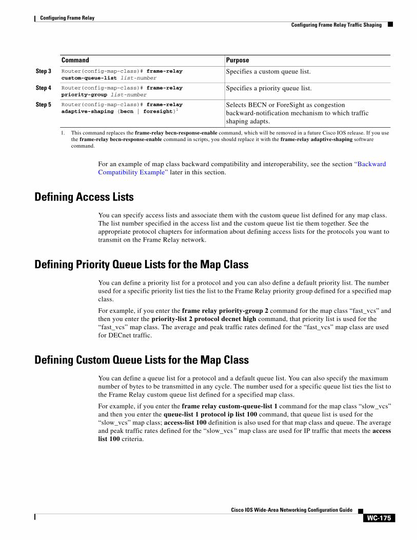
For an example of map class backward compatibility and interoperability, see the section “Backward Compatibility Example” later in this section.
Defining Access Lists You can specify access lists and associate them with the custom queue list defined for any map class. The list number specified in the access list and the custom queue list tie them together. See the appropriate protocol chapters for information about defining access lists for the protocols you want to transmit on the Frame Relay network.
Defining Priority Queue Lists for the Map Class You can define a priority list for a protocol and you can also define a default priority list. The number used for a specific priority list ties the list to the Frame Relay priority group defined for a specified map class.
For example, if you enter the frame relay priority-group 2 command for the map class “fast_vcs” and then you enter the priority-list 2 protocol decnet high command, that priority list is used for the “fast_vcs” map class. The average and peak traffic rates defined for the “fast_vcs” map class are used for DECnet traffic.
Defining Custom Queue Lists for the Map ClassYou can define a queue list for a protocol and a default queue list. You can also specify the maximum number of bytes to be transmitted in any cycle. The number used for a specific queue list ties the list to the Frame Relay custom queue list defined for a specified map class.
For example, if you enter the frame relay custom-queue-list 1 command for the map class “slow_vcs” and then you enter the queue-list 1 protocol ip list 100 command, that queue list is used for the “slow_vcs” map class; access-list 100 definition is also used for that map class and queue. The average and peak traffic rates defined for the “slow_vcs” map class are used for IP traffic that meets the access list 100 criteria.
Step 3 Router(config-map-class)# frame-relay custom-queue-list list-number
Specifies a custom queue list.
Step 4 Router(config-map-class)# frame-relay priority-group list-number
Specifies a priority queue list.
Step 5 Router(config-map-class)# frame-relay adaptive-shaping {becn | foresight}1
Selects BECN or ForeSight as congestion backward-notification mechanism to which traffic shaping adapts.
1. This command replaces the frame-relay becn-response-enable command, which will be removed in a future Cisco IOS release. If you use the frame-relay becn-response-enable command in scripts, you should replace it with the frame-relay adaptive-shaping software command.
Command Purpose
Configuring Frame RelayConfiguring Frame Relay Switching
WC-176Cisco IOS Wide-Area Networking Configuration Guide
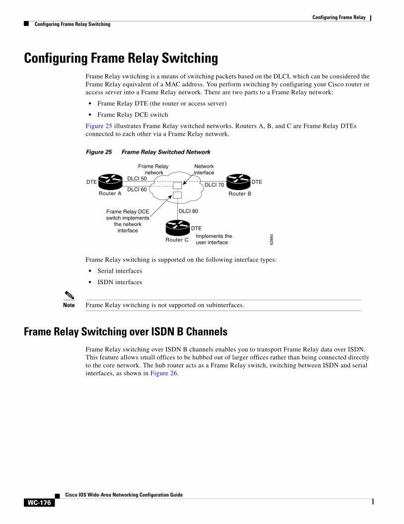
Configuring Frame Relay Switching Frame Relay switching is a means of switching packets based on the DLCI, which can be considered the Frame Relay equivalent of a MAC address. You perform switching by configuring your Cisco router or access server into a Frame Relay network. There are two parts to a Frame Relay network:
• Frame Relay DTE (the router or access server)
• Frame Relay DCE switch
Figure 25 illustrates Frame Relay switched networks. Routers A, B, and C are Frame Relay DTEs connected to each other via a Frame Relay network.
Figure 25 Frame Relay Switched Network
Frame Relay switching is supported on the following interface types:
• Serial interfaces
• ISDN interfaces
Note Frame Relay switching is not supported on subinterfaces.
Frame Relay Switching over ISDN B ChannelsFrame Relay switching over ISDN B channels enables you to transport Frame Relay data over ISDN. This feature allows small offices to be hubbed out of larger offices rather than being connected directly to the core network. The hub router acts as a Frame Relay switch, switching between ISDN and serial interfaces, as shown in Figure 26.
Router C
Router A Router B
Frame Relay network
6286
0
Networkinterface
DLCI 50
DLCI 60DLCI 70
DLCI 80
DTE
DTEDTE
Implements the user interface
Frame Relay DCEswitch implements
the networkinterface
Configuring Frame RelayConfiguring Frame Relay Switching
WC-177Cisco IOS Wide-Area Networking Configuration Guide
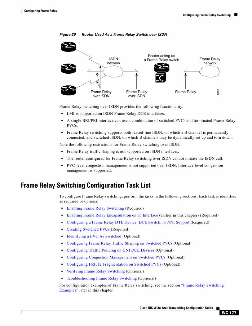
Figure 26 Router Used As a Frame Relay Switch over ISDN
Frame Relay switching over ISDN provides the following functionality:
• LMI is supported on ISDN Frame Relay DCE interfaces.
• A single BRI/PRI interface can use a combination of switched PVCs and terminated Frame Relay PVCs.
• Frame Relay switching supports both leased-line ISDN, on which a B channel is permanently connected, and switched ISDN, on which B channels may be dynamically set up and torn down.
Note the following restrictions for Frame Relay switching over ISDN:
• Frame Relay traffic shaping is not supported on ISDN interfaces.
• The router configured for Frame Relay switching over ISDN cannot initiate the ISDN call.
• PVC-level congestion management is not supported over ISDN. Interface-level congestion management is supported.
Frame Relay Switching Configuration Task ListTo configure Frame Relay switching, perform the tasks in the following sections. Each task is identified as required or optional.
• Enabling Frame Relay Switching (Required)
• Enabling Frame Relay Encapsulation on an Interface (earlier in this chapter) (Required)
• Configuring a Frame Relay DTE Device, DCE Switch, or NNI Support (Required)
• Creating Switched PVCs (Required)
• Identifying a PVC As Switched (Optional)
• Configuring Frame Relay Traffic Shaping on Switched PVCs (Optional)
• Configuring Traffic Policing on UNI DCE Devices (Optional)
• Configuring Congestion Management on Switched PVCs (Optional)
• Configuring FRF.12 Fragmentation on Switched PVCs (Optional)
• Verifying Frame Relay Switching (Optional)
• Troubleshooting Frame Relay Switching (Optional)
For configuration examples of Frame Relay switching, see the section “Frame Relay Switching Examples” later in this chapter.
Frame Relayover ISDN
ISDNnetwork
Frame Relaynetwork
Router acting asa Frame Relay switch
4008
1
Frame Relayover ISDN
Frame Relay
Configuring Frame RelayConfiguring Frame Relay Switching
WC-178Cisco IOS Wide-Area Networking Configuration Guide
Enabling Frame Relay Switching
You must enable packet switching before you can configure it on a Frame Relay DTE or DCE, or with Network-to-Network Interface (NNI) support. Do so by using the following command in global configuration mode before configuring the switch type:
Configuring a Frame Relay DTE Device, DCE Switch, or NNI Support
You can configure an interface as a DTE device or a DCE switch, or as a switch connected to a switch to support NNI connections. (DTE is the default.) To do so, use the following command in interface configuration mode:
Creating Switched PVCs
To create a switched PVC over ISDN, or to create a switched PVC on which traffic shaping, traffic policing, and congestion management can be configured, use the following command in global configuration mode:
To create a switched PVC with a static route, use the following command in interface configuration mode:
Note Static routes cannot be configured over tunnel interfaces on the Cisco 800 series, 1600 series, and 1700 series platforms. Static routes can only be configured over tunnel interfaces on platforms that have the Enterprise feature set.
Command Purpose
Router(config)# frame-relay switching Enables Frame Relay switching.
Command Purpose
Router(config-if)# frame-relay intf-type [dce | dte | nni]
Configures a Frame Relay DTE device or DCE switch.
Command Purpose
Router(config)# connect connection-name interface dlci interface dlci
Defines connections between Frame Relay PVCs.
Command PurposeRouter(config-if)# frame-relay route in-dlci interface out-interface-type out-interface-number out-dlci
Specifies a static route for PVC switching.
Configuring Frame RelayConfiguring Frame Relay Switching
WC-179Cisco IOS Wide-Area Networking Configuration Guide
Identifying a PVC As Switched
Before you can associate a map class with a switched PVC, you must identify the PVC as being switched. To identify a PVC as switched, use the following command in interface configuration mode:
Configuring Frame Relay Traffic Shaping on Switched PVCs
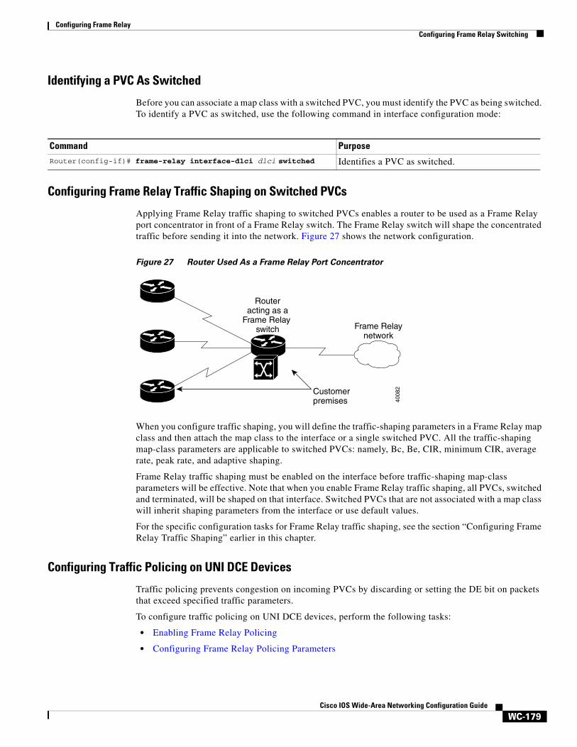
Applying Frame Relay traffic shaping to switched PVCs enables a router to be used as a Frame Relay port concentrator in front of a Frame Relay switch. The Frame Relay switch will shape the concentrated traffic before sending it into the network. Figure 27 shows the network configuration.
Figure 27 Router Used As a Frame Relay Port Concentrator
When you configure traffic shaping, you will define the traffic-shaping parameters in a Frame Relay map class and then attach the map class to the interface or a single switched PVC. All the traffic-shaping map-class parameters are applicable to switched PVCs: namely, Bc, Be, CIR, minimum CIR, average rate, peak rate, and adaptive shaping.
Frame Relay traffic shaping must be enabled on the interface before traffic-shaping map-class parameters will be effective. Note that when you enable Frame Relay traffic shaping, all PVCs, switched and terminated, will be shaped on that interface. Switched PVCs that are not associated with a map class will inherit shaping parameters from the interface or use default values.
For the specific configuration tasks for Frame Relay traffic shaping, see the section “Configuring Frame Relay Traffic Shaping” earlier in this chapter.
Configuring Traffic Policing on UNI DCE Devices
Traffic policing prevents congestion on incoming PVCs by discarding or setting the DE bit on packets that exceed specified traffic parameters.
To configure traffic policing on UNI DCE devices, perform the following tasks:
• Enabling Frame Relay Policing
• Configuring Frame Relay Policing Parameters
Command Purpose
Router(config-if)# frame-relay interface-dlci dlci switched Identifies a PVC as switched.
Frame Relaynetwork
Routeracting as a
Frame Relay switch
Customerpremises 40
082
Configuring Frame RelayConfiguring Frame Relay Switching
WC-180Cisco IOS Wide-Area Networking Configuration Guide
Enabling Frame Relay Policing
To enable Frame Relay policing on a interface, use the following command in interface configuration mode:
Configuring Frame Relay Policing Parameters
To configure policing parameters in a Frame Relay map class, use one or more of the following commands in map-class configuration mode:
You can associate the map class with the interface or individual switched PVCs. Switched PVCs that are not associated with a map class will inherit policing parameters from the interface.
If you use a map class to configure both traffic policing and shaping, use the in keyword to specify incoming traffic for policing and the out keyword to specify outgoing traffic for shaping. If you configure shaping on one segment of a switched PVC and policing on the other, the shaping parameters will be derived from the policing parameters unless you specifically define shaping parameters in the map class.
Configuring Congestion Management on Switched PVCs
Frame Relay congestion management can be used to manage outgoing traffic congestion on switched PVCs. When Frame Relay congestion management is enabled, one way that the router manages congestion is by setting backward explicit congestion notification (BECN) and forward explicit congestion notification (FECN) bits on packets. When a switched PVC or interface is congested, packets experiencing congestion are marked with the FECN bit, and packets traveling in the reverse direction are marked with the BECN bit. When these bits reach a user device at the end of the network, the user device can react to the ECN bits and adjust the flow of traffic.
When the output interface queue reaches or exceeds the ECN excess threshold, all Frame Relay DE bit packets on all PVCs crossing that interface will be marked with FECN or BECN, depending on their direction of travel. When the queue reaches or exceeds the ECN committed threshold, all Frame Relay packets will be marked with FECN or BECN.
Command Purpose
Router(config-if)# frame-relay policing Enables Frame Relay policing on all switched PVCs on the interface.
Command Purpose
Router(config-map-class)# frame-relay cir {in | out} bps Sets the CIR for a Frame Relay PVC, in bits per second.
Router(config-map-class)# frame-relay bc {in | out} bits Sets the committed burst size for a Frame Relay PVC, in bits.
Router(config-map-class)# frame-relay be {in | out} bits Sets the excess burst size for a Frame Relay PVC, in bits.
Router(config-map-class)# frame-relay tc milliseconds Sets the measurement interval for policing incoming traffic on a PVC when the CIR is zero, in milliseconds.
Configuring Frame RelayConfiguring Frame Relay Switching
WC-181Cisco IOS Wide-Area Networking Configuration Guide
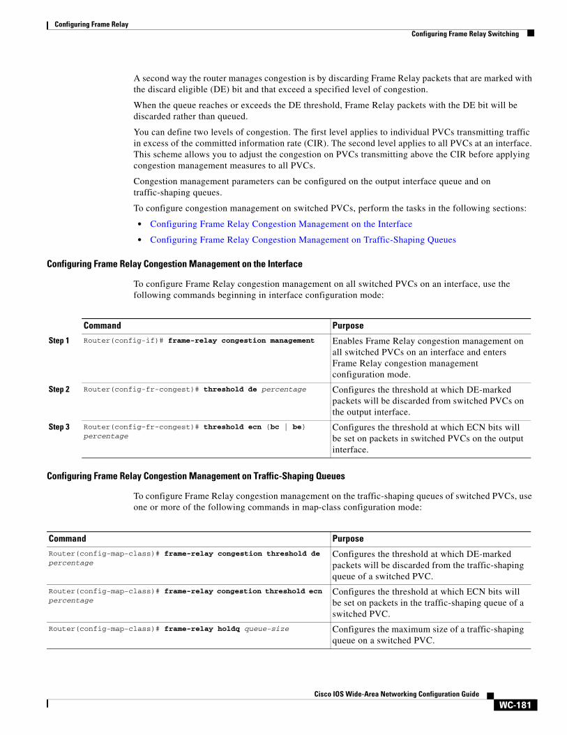
A second way the router manages congestion is by discarding Frame Relay packets that are marked with the discard eligible (DE) bit and that exceed a specified level of congestion.
When the queue reaches or exceeds the DE threshold, Frame Relay packets with the DE bit will be discarded rather than queued.
You can define two levels of congestion. The first level applies to individual PVCs transmitting traffic in excess of the committed information rate (CIR). The second level applies to all PVCs at an interface. This scheme allows you to adjust the congestion on PVCs transmitting above the CIR before applying congestion management measures to all PVCs.
Congestion management parameters can be configured on the output interface queue and on traffic-shaping queues.
To configure congestion management on switched PVCs, perform the tasks in the following sections:
• Configuring Frame Relay Congestion Management on the Interface
• Configuring Frame Relay Congestion Management on Traffic-Shaping Queues
Configuring Frame Relay Congestion Management on the Interface
To configure Frame Relay congestion management on all switched PVCs on an interface, use the following commands beginning in interface configuration mode:
Configuring Frame Relay Congestion Management on Traffic-Shaping Queues
To configure Frame Relay congestion management on the traffic-shaping queues of switched PVCs, use one or more of the following commands in map-class configuration mode:
Command Purpose
Step 1 Router(config-if)# frame-relay congestion management Enables Frame Relay congestion management on all switched PVCs on an interface and enters Frame Relay congestion management configuration mode.
Step 2 Router(config-fr-congest)# threshold de percentage Configures the threshold at which DE-marked packets will be discarded from switched PVCs on the output interface.
Step 3 Router(config-fr-congest)# threshold ecn {bc | be} percentage
Configures the threshold at which ECN bits will be set on packets in switched PVCs on the output interface.
Command Purpose
Router(config-map-class)# frame-relay congestion threshold de percentage
Configures the threshold at which DE-marked packets will be discarded from the traffic-shaping queue of a switched PVC.
Router(config-map-class)# frame-relay congestion threshold ecn percentage
Configures the threshold at which ECN bits will be set on packets in the traffic-shaping queue of a switched PVC.
Router(config-map-class)# frame-relay holdq queue-size Configures the maximum size of a traffic-shaping queue on a switched PVC.
Configuring Frame RelayConfiguring Frame Relay Switching
WC-182Cisco IOS Wide-Area Networking Configuration Guide
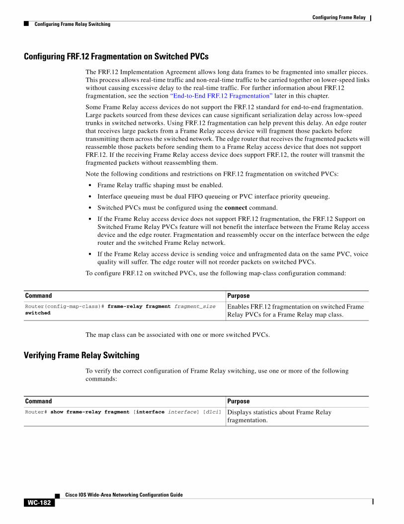
Configuring FRF.12 Fragmentation on Switched PVCs
The FRF.12 Implementation Agreement allows long data frames to be fragmented into smaller pieces. This process allows real-time traffic and non-real-time traffic to be carried together on lower-speed links without causing excessive delay to the real-time traffic. For further information about FRF.12 fragmentation, see the section “End-to-End FRF.12 Fragmentation” later in this chapter.
Some Frame Relay access devices do not support the FRF.12 standard for end-to-end fragmentation. Large packets sourced from these devices can cause significant serialization delay across low-speed trunks in switched networks. Using FRF.12 fragmentation can help prevent this delay. An edge router that receives large packets from a Frame Relay access device will fragment those packets before transmitting them across the switched network. The edge router that receives the fragmented packets will reassemble those packets before sending them to a Frame Relay access device that does not support FRF.12. If the receiving Frame Relay access device does support FRF.12, the router will transmit the fragmented packets without reassembling them.
Note the following conditions and restrictions on FRF.12 fragmentation on switched PVCs:
• Frame Relay traffic shaping must be enabled.
• Interface queueing must be dual FIFO queueing or PVC interface priority queueing.
• Switched PVCs must be configured using the connect command.
• If the Frame Relay access device does not support FRF.12 fragmentation, the FRF.12 Support on Switched Frame Relay PVCs feature will not benefit the interface between the Frame Relay access device and the edge router. Fragmentation and reassembly occur on the interface between the edge router and the switched Frame Relay network.
• If the Frame Relay access device is sending voice and unfragmented data on the same PVC, voice quality will suffer. The edge router will not reorder packets on switched PVCs.
To configure FRF.12 on switched PVCs, use the following map-class configuration command:
The map class can be associated with one or more switched PVCs.
Verifying Frame Relay Switching
To verify the correct configuration of Frame Relay switching, use one or more of the following commands:
Command Purpose
Router(config-map-class)# frame-relay fragment fragment_size switched
Enables FRF.12 fragmentation on switched Frame Relay PVCs for a Frame Relay map class.
Command Purpose
Router# show frame-relay fragment [interface interface] [dlci] Displays statistics about Frame Relay fragmentation.
Configuring Frame RelayCustomizing Frame Relay for Your Network
WC-183Cisco IOS Wide-Area Networking Configuration Guide
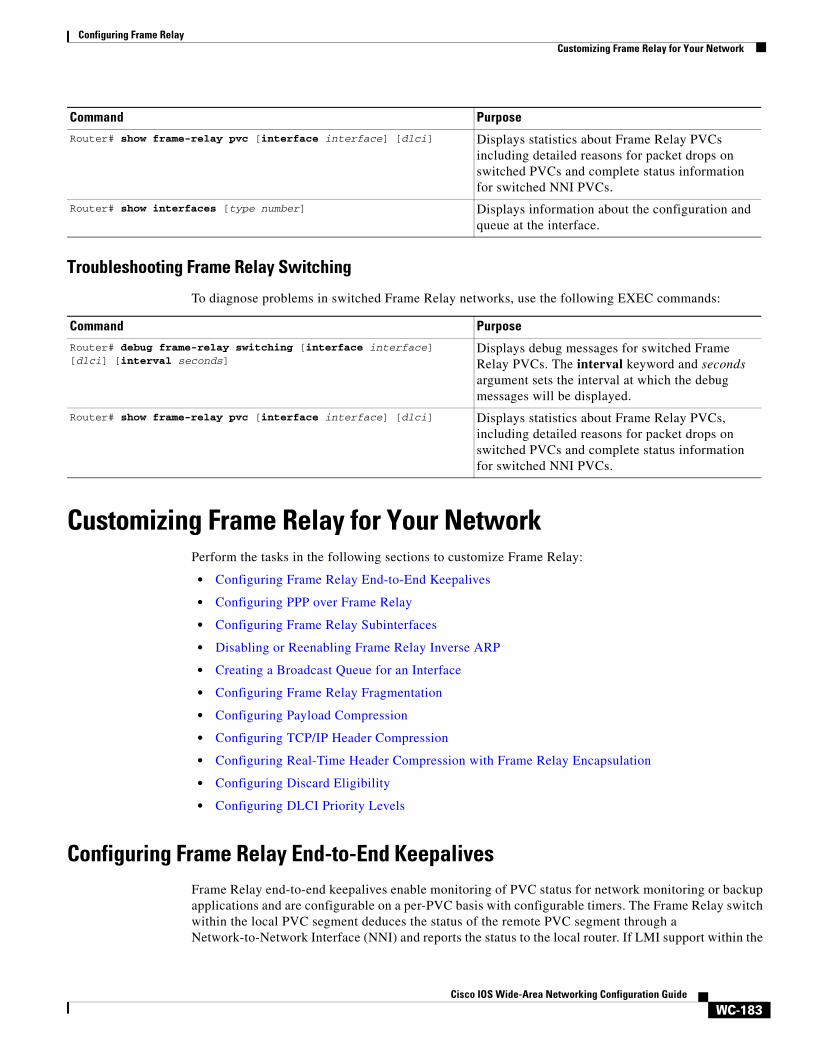
Troubleshooting Frame Relay Switching
To diagnose problems in switched Frame Relay networks, use the following EXEC commands:
Customizing Frame Relay for Your NetworkPerform the tasks in the following sections to customize Frame Relay:
• Configuring Frame Relay End-to-End Keepalives
• Configuring PPP over Frame Relay
• Configuring Frame Relay Subinterfaces
• Disabling or Reenabling Frame Relay Inverse ARP
• Creating a Broadcast Queue for an Interface
• Configuring Frame Relay Fragmentation
• Configuring Payload Compression
• Configuring TCP/IP Header Compression
• Configuring Real-Time Header Compression with Frame Relay Encapsulation
• Configuring Discard Eligibility
• Configuring DLCI Priority Levels
Configuring Frame Relay End-to-End KeepalivesFrame Relay end-to-end keepalives enable monitoring of PVC status for network monitoring or backup applications and are configurable on a per-PVC basis with configurable timers. The Frame Relay switch within the local PVC segment deduces the status of the remote PVC segment through a Network-to-Network Interface (NNI) and reports the status to the local router. If LMI support within the
Router# show frame-relay pvc [interface interface] [dlci] Displays statistics about Frame Relay PVCs including detailed reasons for packet drops on switched PVCs and complete status information for switched NNI PVCs.
Router# show interfaces [type number] Displays information about the configuration and queue at the interface.
Command Purpose
Command Purpose
Router# debug frame-relay switching [interface interface] [dlci] [interval seconds]
Displays debug messages for switched Frame Relay PVCs. The interval keyword and seconds argument sets the interval at which the debug messages will be displayed.
Router# show frame-relay pvc [interface interface] [dlci] Displays statistics about Frame Relay PVCs, including detailed reasons for packet drops on switched PVCs and complete status information for switched NNI PVCs.
Configuring Frame RelayCustomizing Frame Relay for Your Network
WC-184Cisco IOS Wide-Area Networking Configuration Guide
switch is not end-to-end, end-to-end keepalives are the only source of information about the remote router. End-to-end keepalives verify that data is getting through to a remote device via end-to-end communication.
Each PVC connecting two end devices needs two separate keepalive systems, because the upstream path may not be the same as the downstream path. One system sends out requests and handles responses to those requests—the send side—while the other system handles and replies to requests from the device at the other end of the PVC—the receive side. The send side on one device communicates with the receive side on the other device, and vice versa.
The send side sends out a keepalive request and waits for a reply to its request. If a reply is received before the timer expires, a send-side Frame Relay end-to-end keepalive is recorded. If no reply is received before the timer expires, an error event is recorded. A number of the most recently recorded events are examined. If enough error events are accumulated, the keepalive status of the VC is changed from up to down, or if enough consecutive successful replies are received, the keepalive status of the VC is changed from down to up. The number of events that will be examined is called the event window.
The receive side is similar to the send side. The receive side waits for requests and sends out replies to those requests. If a request is received before the timer expires, a success event is recorded. If a request is not received, an error event is recorded. If enough error events occur in the event window, the PVC state will be changed from up to down. If enough consecutive success events occur, the state will be changed from down to up.
End-to-end keepalives can be configured in one of four modes: bidirectional, request, reply, or passive-reply.
• In bidirectional mode, both the send side and the receive side are enabled. The send side of the device sends out and waits for replies to keepalive requests from the receive side of the other PVC device. The receive side of the device waits for and replies to keepalive requests from the send side of the other PVC device.
• In request mode, only the send side is enabled, and the device sends out and waits for replies to its keepalive requests.
• In reply mode, only the receive side is enabled, and the device waits for and replies to keepalive requests.
• In passive-reply mode, the device only responds to keepalive requests, but does not set any timers or keep track of any events.
Because end-to-end keepalives allow traffic flow in both directions, they can be used to carry control and configuration information from end to end. Consistency of information between end hosts is critical in applications such as those relating to prioritized traffic and Voice over Frame Relay. Whereas SVCs can convey such information within end-to-end signalling messages, PVCs will benefit from a bidirectional communication mechanism.
End-to-end keepalives are derived from the Frame Relay LMI protocol and work between peer Cisco communications devices. The key difference is that rather than running over the signalling channel, as is the case with LMI, end-to-end keepalives run over individual data channels.
Encapsulation of keepalive packets is proprietary; therefore, the feature is available only on Cisco devices running a software release that supports the Frame Relay End-to-End Keepalive feature.
You must configure both ends of a VC to send keepalives. If one end is configured as bidirectional, the other end must also be configured as bidirectional. If one end is configured as request, the other end must be configured as reply or passive-reply. If one end is configured as reply or passive-reply, the other end must be configured as request
Configuring Frame RelayCustomizing Frame Relay for Your Network
WC-185Cisco IOS Wide-Area Networking Configuration Guide
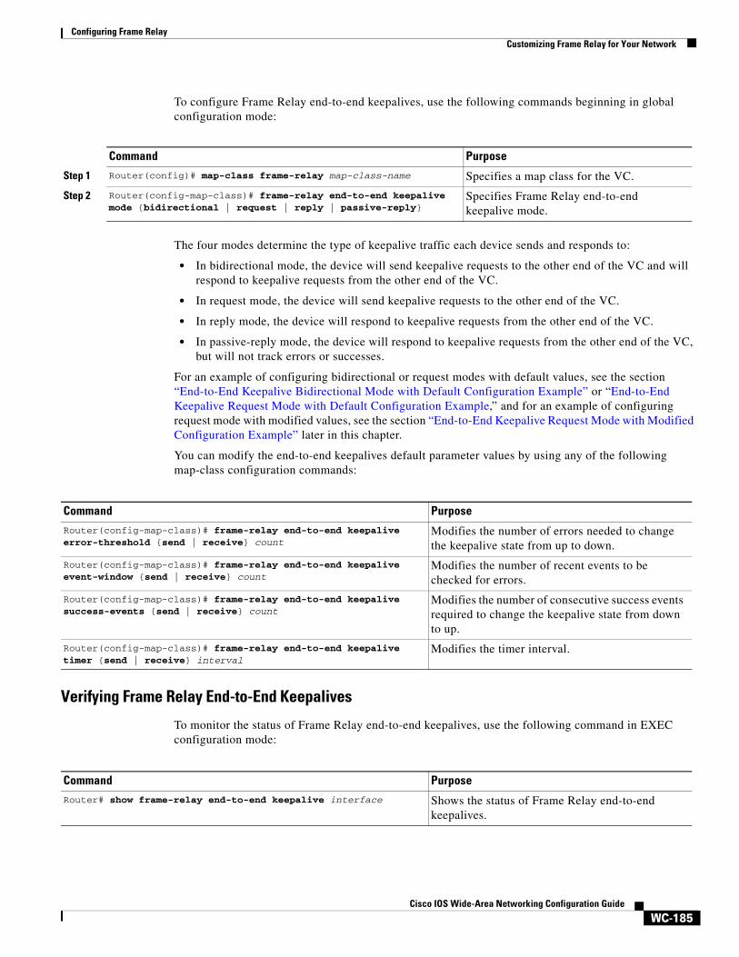
To configure Frame Relay end-to-end keepalives, use the following commands beginning in global configuration mode:
The four modes determine the type of keepalive traffic each device sends and responds to:
• In bidirectional mode, the device will send keepalive requests to the other end of the VC and will respond to keepalive requests from the other end of the VC.
• In request mode, the device will send keepalive requests to the other end of the VC.
• In reply mode, the device will respond to keepalive requests from the other end of the VC.
• In passive-reply mode, the device will respond to keepalive requests from the other end of the VC, but will not track errors or successes.
For an example of configuring bidirectional or request modes with default values, see the section “End-to-End Keepalive Bidirectional Mode with Default Configuration Example” or “End-to-End Keepalive Request Mode with Default Configuration Example,” and for an example of configuring request mode with modified values, see the section “End-to-End Keepalive Request Mode with Modified Configuration Example” later in this chapter.
You can modify the end-to-end keepalives default parameter values by using any of the following map-class configuration commands:
Verifying Frame Relay End-to-End Keepalives
To monitor the status of Frame Relay end-to-end keepalives, use the following command in EXEC configuration mode:
Command Purpose
Step 1 Router(config)# map-class frame-relay map-class-name Specifies a map class for the VC.
Step 2 Router(config-map-class)# frame-relay end-to-end keepalive mode {bidirectional | request | reply | passive-reply}
Specifies Frame Relay end-to-end keepalive mode.
Command Purpose
Router(config-map-class)# frame-relay end-to-end keepalive error-threshold {send | receive} count
Modifies the number of errors needed to change the keepalive state from up to down.
Router(config-map-class)# frame-relay end-to-end keepalive event-window {send | receive} count
Modifies the number of recent events to be checked for errors.
Router(config-map-class)# frame-relay end-to-end keepalive success-events {send | receive} count
Modifies the number of consecutive success events required to change the keepalive state from down to up.
Router(config-map-class)# frame-relay end-to-end keepalive timer {send | receive} interval
Modifies the timer interval.
Command PurposeRouter# show frame-relay end-to-end keepalive interface Shows the status of Frame Relay end-to-end
keepalives.
Configuring Frame RelayCustomizing Frame Relay for Your Network
WC-186Cisco IOS Wide-Area Networking Configuration Guide
Configuring PPP over Frame RelayPoint-to-point protocol (PPP) over Frame Relay allows a router to establish end-to-end PPP sessions over Frame Relay. This is done over a PVC, which is the only circuit currently supported. The PPP session does not occur unless the associated Frame Relay PVC is in an “active” state. The Frame Relay PVC can coexist with other circuits using different Frame Relay encapsulation methods, such as RFC 1490 and the Cisco proprietary method, over the same Frame Relay link. There can be multiple PPP over Frame Relay circuits on one Frame Relay link.
One PPP connection resides on one virtual access interface. This is internally created from a virtual template interface, which contains all necessary PPP and network protocol information and is shared by multiple virtual access interfaces. The virtual access interface is coexistent with the creation of the Frame Relay circuit when the corresponding DLCI is configured. Hardware compression and fancy queueing algorithms, such as weighted fair queueing, custom queueing, and priority queueing, are not applied to virtual access interfaces.
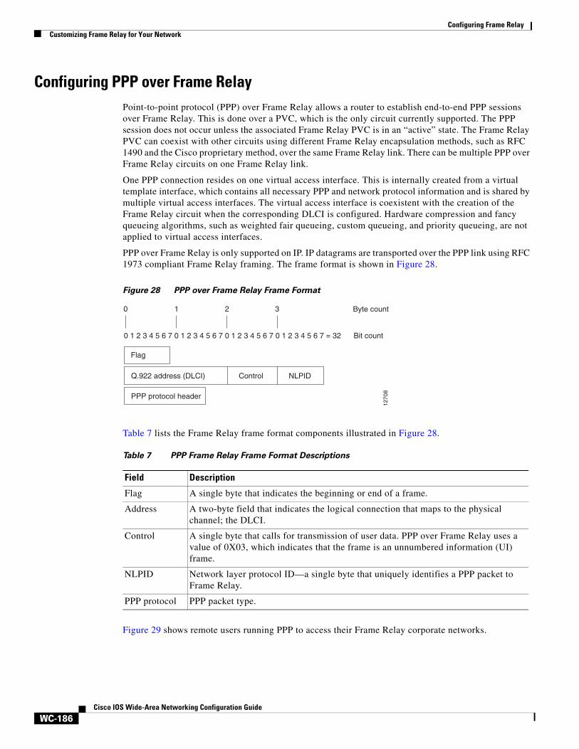
PPP over Frame Relay is only supported on IP. IP datagrams are transported over the PPP link using RFC 1973 compliant Frame Relay framing. The frame format is shown in Figure 28.
Figure 28 PPP over Frame Relay Frame Format
Table 7 lists the Frame Relay frame format components illustrated in Figure 28.
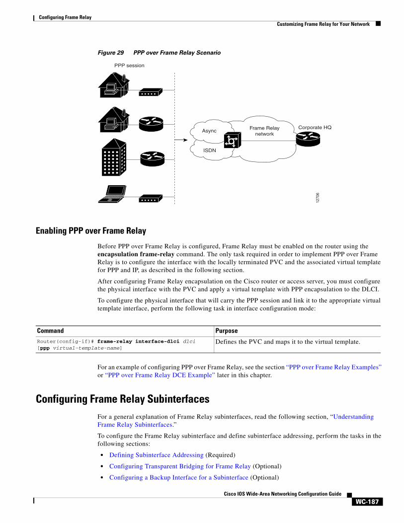
Figure 29 shows remote users running PPP to access their Frame Relay corporate networks.
1270
8
0 1 2 3 4 5 6 7 0 1 2 3 4 5 6 7 0 1 2 3 4 5 6 7 0 1 2 3 4 5 6 7 = 32
0 1 2 3
Flag
Q.922 address (DLCI)
PPP protocol header
Control NLPID
Byte count
Bit count
Table 7 PPP Frame Relay Frame Format Descriptions
Field Description
Flag A single byte that indicates the beginning or end of a frame.
Address A two-byte field that indicates the logical connection that maps to the physical channel; the DLCI.
Control A single byte that calls for transmission of user data. PPP over Frame Relay uses a value of 0X03, which indicates that the frame is an unnumbered information (UI) frame.
NLPID Network layer protocol ID—a single byte that uniquely identifies a PPP packet to Frame Relay.
PPP protocol PPP packet type.
Configuring Frame RelayCustomizing Frame Relay for Your Network
WC-187Cisco IOS Wide-Area Networking Configuration Guide
Figure 29 PPP over Frame Relay Scenario
Enabling PPP over Frame Relay
Before PPP over Frame Relay is configured, Frame Relay must be enabled on the router using the encapsulation frame-relay command. The only task required in order to implement PPP over Frame Relay is to configure the interface with the locally terminated PVC and the associated virtual template for PPP and IP, as described in the following section.
After configuring Frame Relay encapsulation on the Cisco router or access server, you must configure the physical interface with the PVC and apply a virtual template with PPP encapsulation to the DLCI.
To configure the physical interface that will carry the PPP session and link it to the appropriate virtual template interface, perform the following task in interface configuration mode:
For an example of configuring PPP over Frame Relay, see the section “PPP over Frame Relay Examples” or “PPP over Frame Relay DCE Example” later in this chapter.
Configuring Frame Relay Subinterfaces For a general explanation of Frame Relay subinterfaces, read the following section, “Understanding Frame Relay Subinterfaces.”
To configure the Frame Relay subinterface and define subinterface addressing, perform the tasks in the following sections:
• Defining Subinterface Addressing (Required)
• Configuring Transparent Bridging for Frame Relay (Optional)
• Configuring a Backup Interface for a Subinterface (Optional)
PPP session
ISDN
1270
6
Frame Relaynetwork
Corporate HQAsync
Command Purpose
Router(config-if)# frame-relay interface-dlci dlci [ppp virtual-template-name]
Defines the PVC and maps it to the virtual template.
Configuring Frame RelayCustomizing Frame Relay for Your Network
WC-188Cisco IOS Wide-Area Networking Configuration Guide
For a selection of subinterface configuration examples, see the section “Subinterface Examples” later in this chapter.
Understanding Frame Relay Subinterfaces
Frame Relay subinterfaces provide a mechanism for supporting partially meshed Frame Relay networks. Most protocols assume transitivity on a logical network; that is, if station A can talk to station B, and station B can talk to station C, then station A should be able to talk to station C directly. Transitivity is true on LANs, but not on Frame Relay networks unless A is directly connected to C.
Additionally, certain protocols such as AppleTalk and transparent bridging cannot be supported on partially meshed networks because they require split horizon. Split horizon is a routing technique in which a packet received on an interface cannot be sent from the same interface even if received and transmitted on different VCs.
Configuring Frame Relay subinterfaces ensures that a single physical interface is treated as multiple virtual interfaces. This treatment allows you to overcome split horizon rules. Packets received on one virtual interface can be forwarded to another virtual interface even if they are configured on the same physical interface.
Subinterfaces address the limitations of Frame Relay networks by providing a way to subdivide a partially meshed Frame Relay network into a number of smaller, fully meshed (or point-to-point) subnetworks. Each subnetwork is assigned its own network number and appears to the protocols as if it were reachable through a separate interface. (Note that point-to-point subinterfaces can be unnumbered for use with IP, reducing the addressing burden that might otherwise result.)
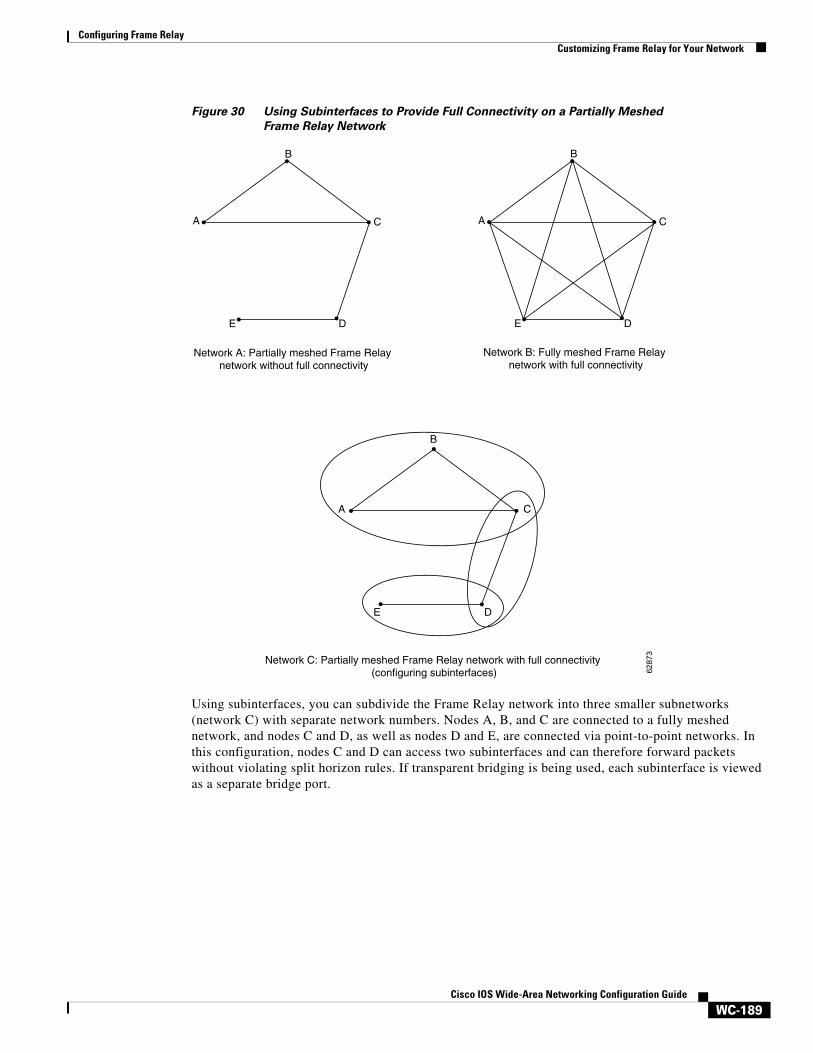
Figure 30 shows a five-node Frame Relay network that is partially meshed (network A). If the entire network is viewed as a single subnetwork (with a single network number assigned), most protocols assume that node A can transmit a packet directly to node E, when in fact it must be relayed through nodes C and D. This network can be made to work with certain protocols (for example, IP), but will not work at all with other protocols (for example, AppleTalk) because nodes C and D will not relay the packet out the same interface on which it was received. One way to make this network work fully is to create a fully meshed network (network B), but doing so requires a large number of PVCs, which may not be economically feasible.
Configuring Frame RelayCustomizing Frame Relay for Your Network
WC-189Cisco IOS Wide-Area Networking Configuration Guide
Figure 30 Using Subinterfaces to Provide Full Connectivity on a Partially Meshed
Frame Relay Network
Using subinterfaces, you can subdivide the Frame Relay network into three smaller subnetworks (network C) with separate network numbers. Nodes A, B, and C are connected to a fully meshed network, and nodes C and D, as well as nodes D and E, are connected via point-to-point networks. In this configuration, nodes C and D can access two subinterfaces and can therefore forward packets without violating split horizon rules. If transparent bridging is being used, each subinterface is viewed as a separate bridge port.
A
B
C
DE
Network B: Fully meshed Frame Relay network with full connectivity
A
B
C
DE
Network A: Partially meshed Frame Relay network without full connectivity
Network C: Partially meshed Frame Relay network with full connectivity (configuring subinterfaces) 62
873
B
A C
DE
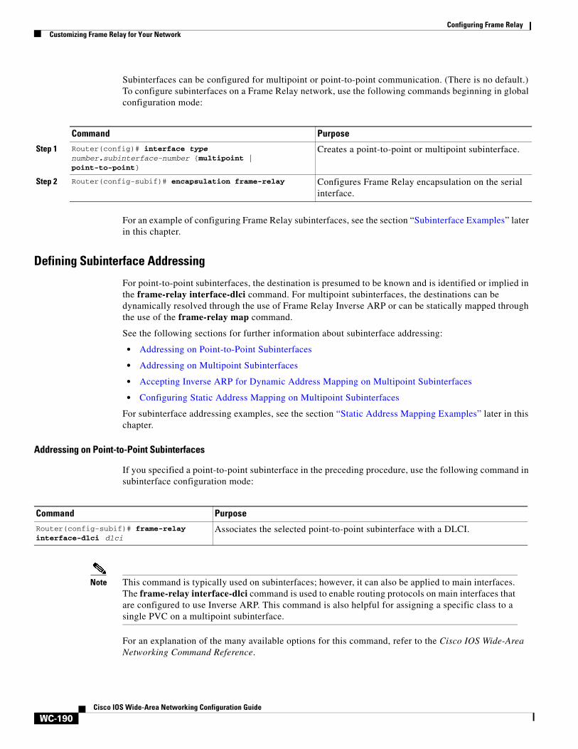
Configuring Frame RelayCustomizing Frame Relay for Your Network
WC-190Cisco IOS Wide-Area Networking Configuration Guide
Subinterfaces can be configured for multipoint or point-to-point communication. (There is no default.) To configure subinterfaces on a Frame Relay network, use the following commands beginning in global configuration mode:
For an example of configuring Frame Relay subinterfaces, see the section “Subinterface Examples” later in this chapter.
Defining Subinterface Addressing
For point-to-point subinterfaces, the destination is presumed to be known and is identified or implied in the frame-relay interface-dlci command. For multipoint subinterfaces, the destinations can be dynamically resolved through the use of Frame Relay Inverse ARP or can be statically mapped through the use of the frame-relay map command.
See the following sections for further information about subinterface addressing:
• Addressing on Point-to-Point Subinterfaces
• Addressing on Multipoint Subinterfaces
• Accepting Inverse ARP for Dynamic Address Mapping on Multipoint Subinterfaces
• Configuring Static Address Mapping on Multipoint Subinterfaces
For subinterface addressing examples, see the section “Static Address Mapping Examples” later in this chapter.
Addressing on Point-to-Point Subinterfaces
If you specified a point-to-point subinterface in the preceding procedure, use the following command in subinterface configuration mode:
Note This command is typically used on subinterfaces; however, it can also be applied to main interfaces. The frame-relay interface-dlci command is used to enable routing protocols on main interfaces that are configured to use Inverse ARP. This command is also helpful for assigning a specific class to a single PVC on a multipoint subinterface.
For an explanation of the many available options for this command, refer to the Cisco IOS Wide-Area Networking Command Reference.
Command Purpose
Step 1 Router(config)# interface type number.subinterface-number {multipoint | point-to-point}
Creates a point-to-point or multipoint subinterface.
Step 2 Router(config-subif)# encapsulation frame-relay Configures Frame Relay encapsulation on the serial interface.
Command Purpose
Router(config-subif)# frame-relay interface-dlci dlci
Associates the selected point-to-point subinterface with a DLCI.
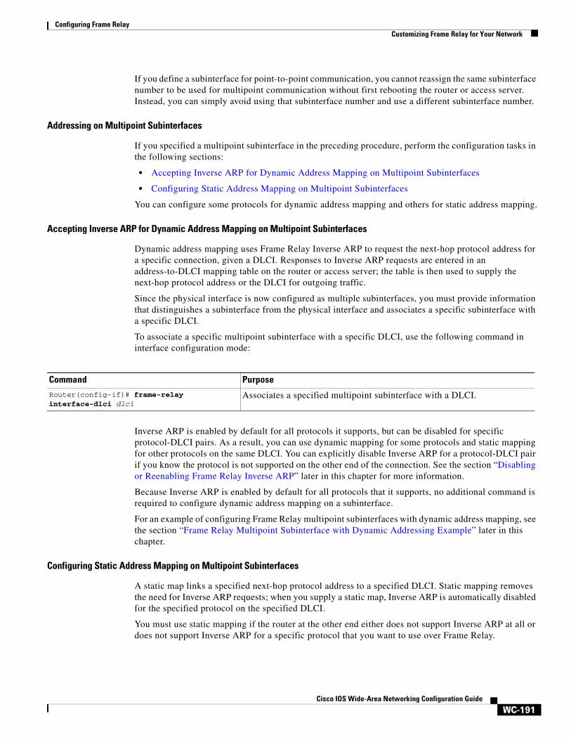
Configuring Frame RelayCustomizing Frame Relay for Your Network
WC-191Cisco IOS Wide-Area Networking Configuration Guide
If you define a subinterface for point-to-point communication, you cannot reassign the same subinterface number to be used for multipoint communication without first rebooting the router or access server. Instead, you can simply avoid using that subinterface number and use a different subinterface number.
Addressing on Multipoint Subinterfaces
If you specified a multipoint subinterface in the preceding procedure, perform the configuration tasks in the following sections:
• Accepting Inverse ARP for Dynamic Address Mapping on Multipoint Subinterfaces
• Configuring Static Address Mapping on Multipoint Subinterfaces
You can configure some protocols for dynamic address mapping and others for static address mapping.
Accepting Inverse ARP for Dynamic Address Mapping on Multipoint Subinterfaces
Dynamic address mapping uses Frame Relay Inverse ARP to request the next-hop protocol address for a specific connection, given a DLCI. Responses to Inverse ARP requests are entered in an address-to-DLCI mapping table on the router or access server; the table is then used to supply the next-hop protocol address or the DLCI for outgoing traffic.
Since the physical interface is now configured as multiple subinterfaces, you must provide information that distinguishes a subinterface from the physical interface and associates a specific subinterface with a specific DLCI.
To associate a specific multipoint subinterface with a specific DLCI, use the following command in interface configuration mode:
Inverse ARP is enabled by default for all protocols it supports, but can be disabled for specific protocol-DLCI pairs. As a result, you can use dynamic mapping for some protocols and static mapping for other protocols on the same DLCI. You can explicitly disable Inverse ARP for a protocol-DLCI pair if you know the protocol is not supported on the other end of the connection. See the section “Disabling or Reenabling Frame Relay Inverse ARP” later in this chapter for more information.
Because Inverse ARP is enabled by default for all protocols that it supports, no additional command is required to configure dynamic address mapping on a subinterface.
For an example of configuring Frame Relay multipoint subinterfaces with dynamic address mapping, see the section “Frame Relay Multipoint Subinterface with Dynamic Addressing Example” later in this chapter.
Configuring Static Address Mapping on Multipoint Subinterfaces
A static map links a specified next-hop protocol address to a specified DLCI. Static mapping removes the need for Inverse ARP requests; when you supply a static map, Inverse ARP is automatically disabled for the specified protocol on the specified DLCI.
You must use static mapping if the router at the other end either does not support Inverse ARP at all or does not support Inverse ARP for a specific protocol that you want to use over Frame Relay.
Command Purpose
Router(config-if)# frame-relay interface-dlci dlci
Associates a specified multipoint subinterface with a DLCI.
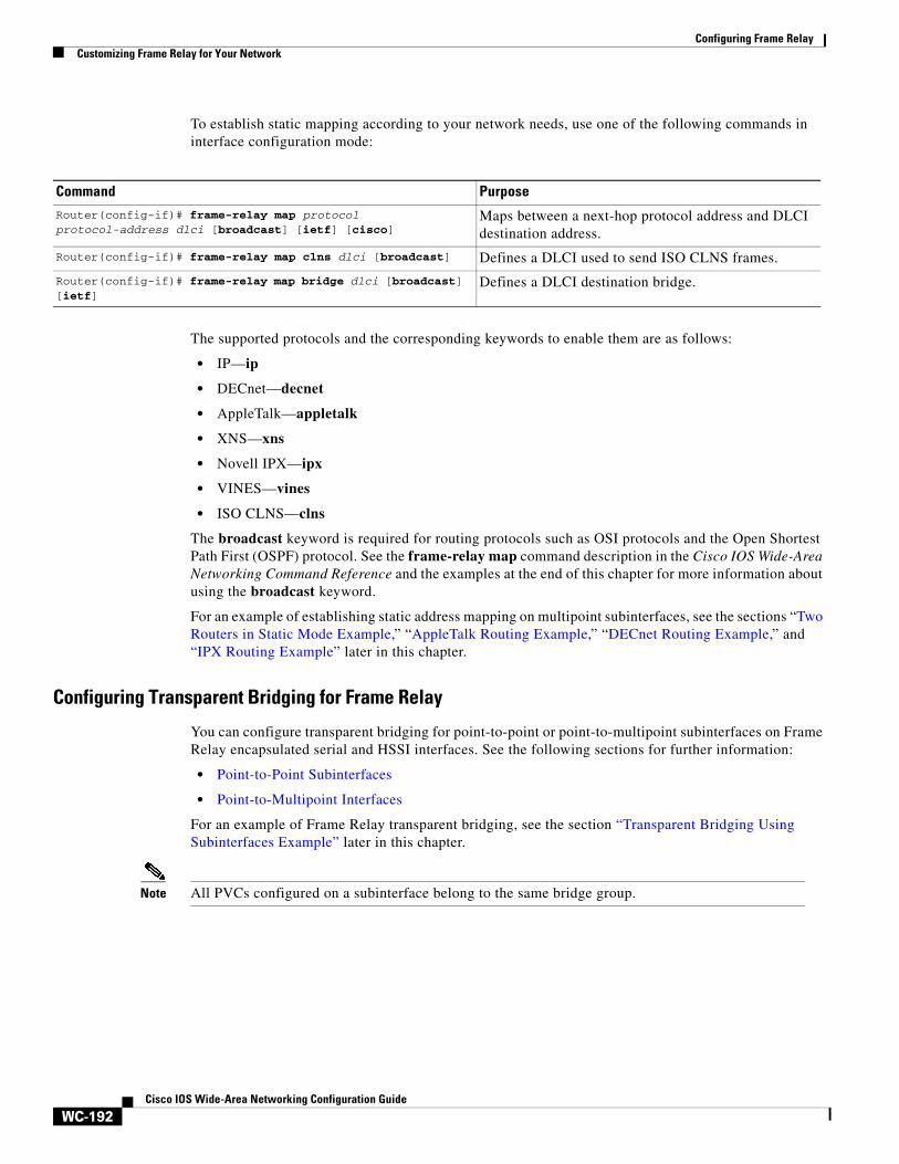
Configuring Frame RelayCustomizing Frame Relay for Your Network
WC-192Cisco IOS Wide-Area Networking Configuration Guide
To establish static mapping according to your network needs, use one of the following commands in interface configuration mode:
The supported protocols and the corresponding keywords to enable them are as follows:
• IP—ip
• DECnet—decnet
• AppleTalk—appletalk
• XNS—xns
• Novell IPX—ipx
• VINES—vines
• ISO CLNS—clns
The broadcast keyword is required for routing protocols such as OSI protocols and the Open Shortest Path First (OSPF) protocol. See the frame-relay map command description in the Cisco IOS Wide-Area Networking Command Reference and the examples at the end of this chapter for more information about using the broadcast keyword.
For an example of establishing static address mapping on multipoint subinterfaces, see the sections “Two Routers in Static Mode Example,” “AppleTalk Routing Example,” “DECnet Routing Example,” and “IPX Routing Example” later in this chapter.
Configuring Transparent Bridging for Frame Relay
You can configure transparent bridging for point-to-point or point-to-multipoint subinterfaces on Frame Relay encapsulated serial and HSSI interfaces. See the following sections for further information:
• Point-to-Point Subinterfaces
• Point-to-Multipoint Interfaces
For an example of Frame Relay transparent bridging, see the section “Transparent Bridging Using Subinterfaces Example” later in this chapter.
Note All PVCs configured on a subinterface belong to the same bridge group.
Command PurposeRouter(config-if)# frame-relay map protocol protocol-address dlci [broadcast] [ietf] [cisco]
Maps between a next-hop protocol address and DLCI destination address.
Router(config-if)# frame-relay map clns dlci [broadcast] Defines a DLCI used to send ISO CLNS frames.
Router(config-if)# frame-relay map bridge dlci [broadcast] [ietf]
Defines a DLCI destination bridge.
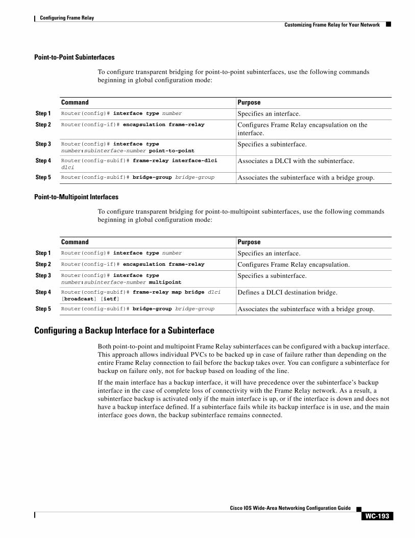
Configuring Frame RelayCustomizing Frame Relay for Your Network
WC-193Cisco IOS Wide-Area Networking Configuration Guide
Point-to-Point Subinterfaces
To configure transparent bridging for point-to-point subinterfaces, use the following commands beginning in global configuration mode:
Point-to-Multipoint Interfaces
To configure transparent bridging for point-to-multipoint subinterfaces, use the following commands beginning in global configuration mode:
Configuring a Backup Interface for a Subinterface
Both point-to-point and multipoint Frame Relay subinterfaces can be configured with a backup interface. This approach allows individual PVCs to be backed up in case of failure rather than depending on the entire Frame Relay connection to fail before the backup takes over. You can configure a subinterface for backup on failure only, not for backup based on loading of the line.
If the main interface has a backup interface, it will have precedence over the subinterface’s backup interface in the case of complete loss of connectivity with the Frame Relay network. As a result, a subinterface backup is activated only if the main interface is up, or if the interface is down and does not have a backup interface defined. If a subinterface fails while its backup interface is in use, and the main interface goes down, the backup subinterface remains connected.
Command Purpose
Step 1 Router(config)# interface type number Specifies an interface.
Step 2 Router(config-if)# encapsulation frame-relay Configures Frame Relay encapsulation on the interface.
Step 3 Router(config)# interface type number:subinterface-number point-to-point
Specifies a subinterface.
Step 4 Router(config-subif)# frame-relay interface-dlci dlci
Associates a DLCI with the subinterface.
Step 5 Router(config-subif)# bridge-group bridge-group Associates the subinterface with a bridge group.
Command Purpose
Step 1 Router(config)# interface type number Specifies an interface.
Step 2 Router(config-if)# encapsulation frame-relay Configures Frame Relay encapsulation.
Step 3 Router(config)# interface type number:subinterface-number multipoint
Specifies a subinterface.
Step 4 Router(config-subif)# frame-relay map bridge dlci [broadcast] [ietf]
Defines a DLCI destination bridge.
Step 5 Router(config-subif)# bridge-group bridge-group Associates the subinterface with a bridge group.
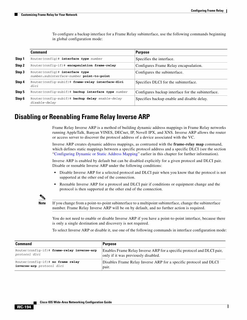
Configuring Frame RelayCustomizing Frame Relay for Your Network
WC-194Cisco IOS Wide-Area Networking Configuration Guide
To configure a backup interface for a Frame Relay subinterface, use the following commands beginning in global configuration mode:
Disabling or Reenabling Frame Relay Inverse ARPFrame Relay Inverse ARP is a method of building dynamic address mappings in Frame Relay networks running AppleTalk, Banyan VINES, DECnet, IP, Novell IPX, and XNS. Inverse ARP allows the router or access server to discover the protocol address of a device associated with the VC.
Inverse ARP creates dynamic address mappings, as contrasted with the frame-relay map command, which defines static mappings between a specific protocol address and a specific DLCI (see the section “Configuring Dynamic or Static Address Mapping” earlier in this chapter for further information).
Inverse ARP is enabled by default but can be disabled explicitly for a given protocol and DLCI pair. Disable or reenable Inverse ARP under the following conditions:
• Disable Inverse ARP for a selected protocol and DLCI pair when you know that the protocol is not supported at the other end of the connection.
• Reenable Inverse ARP for a protocol and DLCI pair if conditions or equipment change and the protocol is then supported at the other end of the connection.
Note If you change from a point-to-point subinterface to a multipoint subinterface, change the subinterface number. Frame Relay Inverse ARP will be on by default, and no further action is required.
You do not need to enable or disable Inverse ARP if you have a point-to-point interface, because there is only a single destination and discovery is not required.
To select Inverse ARP or disable it, use one of the following commands in interface configuration mode:
Command Purpose
Step 1 Router(config)# interface type number Specifies the interface.
Step 2 Router(config-if)# encapsulation frame-relay Configures Frame Relay encapsulation.
Step 3 Router(config)# interface type number.subinterface-number point-to-point
Configures the subinterface.
Step 4 Router(config-subif)# frame-relay interface-dlci dlci
Specifies DLCI for the subinterface.
Step 5 Router(config-subif)# backup interface type number Configures backup interface for the subinterface.
Step 6 Router(config-subif)# backup delay enable-delay disable-delay
Specifies backup enable and disable delay.
Command PurposeRouter(config-if)# frame-relay inverse-arp protocol dlci
Enables Frame Relay Inverse ARP for a specific protocol and DLCI pair, only if it was previously disabled.
Router(config-if)# no frame relay inverse-arp protocol dlci
Disables Frame Relay Inverse ARP for a specific protocol and DLCI pair.
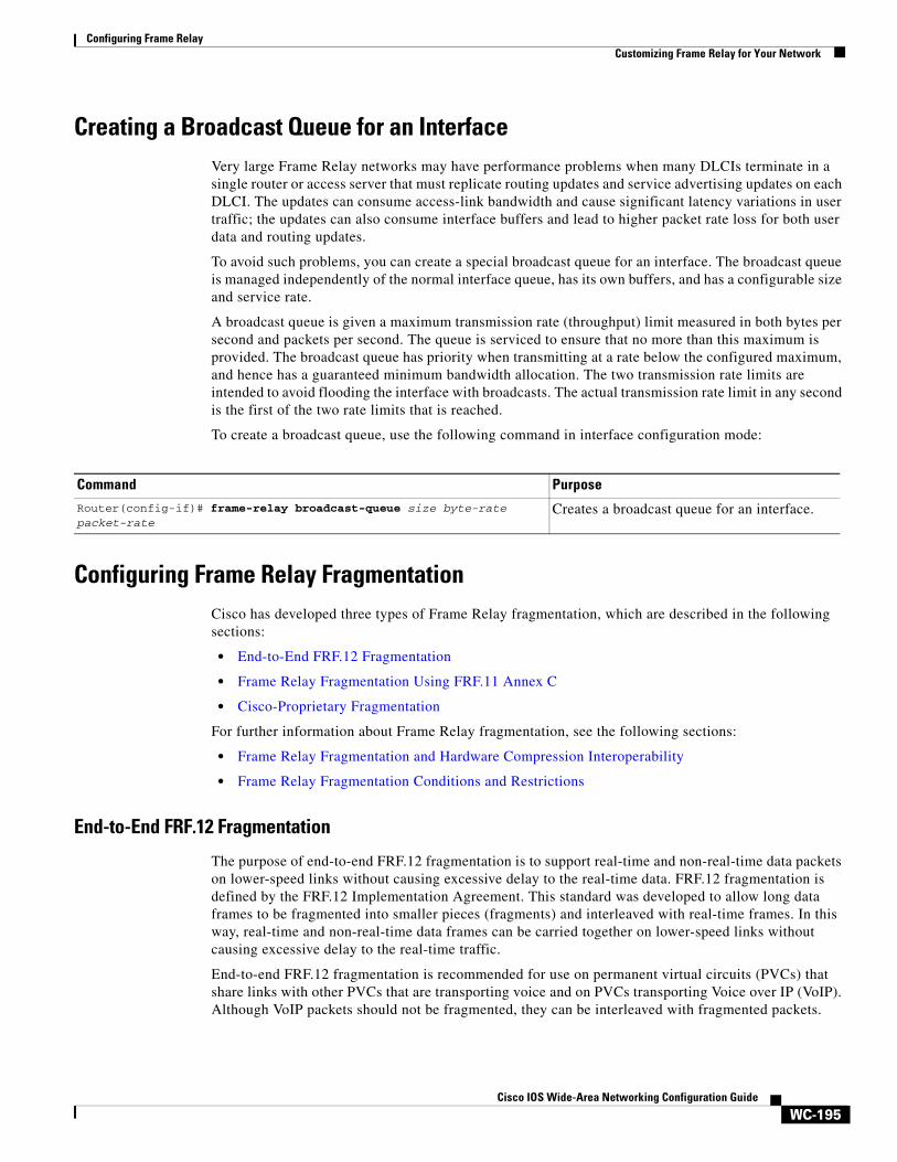
Configuring Frame RelayCustomizing Frame Relay for Your Network
WC-195Cisco IOS Wide-Area Networking Configuration Guide
Creating a Broadcast Queue for an InterfaceVery large Frame Relay networks may have performance problems when many DLCIs terminate in a single router or access server that must replicate routing updates and service advertising updates on each DLCI. The updates can consume access-link bandwidth and cause significant latency variations in user traffic; the updates can also consume interface buffers and lead to higher packet rate loss for both user data and routing updates.
To avoid such problems, you can create a special broadcast queue for an interface. The broadcast queue is managed independently of the normal interface queue, has its own buffers, and has a configurable size and service rate.
A broadcast queue is given a maximum transmission rate (throughput) limit measured in both bytes per second and packets per second. The queue is serviced to ensure that no more than this maximum is provided. The broadcast queue has priority when transmitting at a rate below the configured maximum, and hence has a guaranteed minimum bandwidth allocation. The two transmission rate limits are intended to avoid flooding the interface with broadcasts. The actual transmission rate limit in any second is the first of the two rate limits that is reached.
To create a broadcast queue, use the following command in interface configuration mode:
Configuring Frame Relay FragmentationCisco has developed three types of Frame Relay fragmentation, which are described in the following sections:
• End-to-End FRF.12 Fragmentation
• Frame Relay Fragmentation Using FRF.11 Annex C
• Cisco-Proprietary Fragmentation
For further information about Frame Relay fragmentation, see the following sections:
• Frame Relay Fragmentation and Hardware Compression Interoperability
• Frame Relay Fragmentation Conditions and Restrictions
End-to-End FRF.12 Fragmentation
The purpose of end-to-end FRF.12 fragmentation is to support real-time and non-real-time data packets on lower-speed links without causing excessive delay to the real-time data. FRF.12 fragmentation is defined by the FRF.12 Implementation Agreement. This standard was developed to allow long data frames to be fragmented into smaller pieces (fragments) and interleaved with real-time frames. In this way, real-time and non-real-time data frames can be carried together on lower-speed links without causing excessive delay to the real-time traffic.
End-to-end FRF.12 fragmentation is recommended for use on permanent virtual circuits (PVCs) that share links with other PVCs that are transporting voice and on PVCs transporting Voice over IP (VoIP). Although VoIP packets should not be fragmented, they can be interleaved with fragmented packets.
Command Purpose
Router(config-if)# frame-relay broadcast-queue size byte-rate packet-rate
Creates a broadcast queue for an interface.
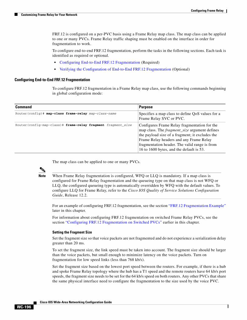
Configuring Frame RelayCustomizing Frame Relay for Your Network
WC-196Cisco IOS Wide-Area Networking Configuration Guide
FRF.12 is configured on a per-PVC basis using a Frame Relay map class. The map class can be applied to one or many PVCs. Frame Relay traffic shaping must be enabled on the interface in order for fragmentation to work.
To configure end-to-end FRF.12 fragmentation, perform the tasks in the following sections. Each task is identified as required or optional.
• Configuring End-to-End FRF.12 Fragmentation (Required)
• Verifying the Configuration of End-to-End FRF.12 Fragmentation (Optional)
Configuring End-to-End FRF.12 Fragmentation
To configure FRF.12 fragmentation in a Frame Relay map class, use the following commands beginning in global configuration mode:
The map class can be applied to one or many PVCs.
Note When Frame Relay fragmentation is configured, WFQ or LLQ is mandatory. If a map class is configured for Frame Relay fragmentation and the queueing type on that map class is not WFQ or LLQ, the configured queueing type is automatically overridden by WFQ with the default values. To configure LLQ for Frame Relay, refer to the Cisco IOS Quality of Service Solutions Configuration Guide, Release 12.2.
For an example of configuring FRF.12 fragmentation, see the section “FRF.12 Fragmentation Example” later in this chapter.
For information about configuring FRF.12 fragmentation on switched Frame Relay PVCs, see the section “Configuring FRF.12 Fragmentation on Switched PVCs” earlier in this chapter.
Setting the Fragment Size
Set the fragment size so that voice packets are not fragmented and do not experience a serialization delay greater than 20 ms.
To set the fragment size, the link speed must be taken into account. The fragment size should be larger than the voice packets, but small enough to minimize latency on the voice packets. Turn on fragmentation for low speed links (less than 768 kb/s).
Set the fragment size based on the lowest port speed between the routers. For example, if there is a hub and spoke Frame Relay topology where the hub has a T1 speed and the remote routers have 64 kb/s port speeds, the fragment size needs to be set for the 64 kb/s speed on both routers. Any other PVCs that share the same physical interface need to configure the fragmentation to the size used by the voice PVC.
Command Purpose
Router(config)# map-class frame-relay map-class-name Specifies a map class to define QoS values for a Frame Relay SVC or PVC.
Router(config-map-class)# frame-relay fragment fragment_size Configures Frame Relay fragmentation for the map class. The fragment_size argument defines the payload size of a fragment; it excludes the Frame Relay headers and any Frame Relay fragmentation header. The valid range is from 16 to 1600 bytes, and the default is 53.
Configuring Frame RelayCustomizing Frame Relay for Your Network
WC-197Cisco IOS Wide-Area Networking Configuration Guide
If the lowest link speed in the path is 64 kb/s, the recommended fragment size (for 10 ms serialization delay) is 80 bytes. If the lowest link speed is 128 kb/s, the recommended fragment size is 160 bytes.
For more information, refer to the “Fragmentation (FRF.12)” section in the VoIP over Frame Relay with Quality of Service (Fragmentation, Traffic Shaping, LLQ / IP RTP Priority) document.
Verifying the Configuration of End-to-End FRF.12 Fragmentation
To verify FRF.12 fragmentation, use one or more of the following EXEC commands:
Frame Relay Fragmentation Using FRF.11 Annex C
When VoFR (FRF.11) and fragmentation are both configured on a PVC, the Frame Relay fragments are sent in the FRF.11 Annex C format. This fragmentation is used when FRF.11 voice traffic is sent on the PVC, and it uses the FRF.11 Annex C format for data.
With FRF.11, all data packets contain fragmentation headers, regardless of size. This form of fragmentation is not recommended for use with Voice over IP (VoIP).
See the chapter “Configuring Voice over Frame Relay” in the Cisco IOS Voice, Video, and Fax Configuration Guide for configuration tasks and examples for Frame Relay fragmentation using FRF.11 Annex C.
Cisco-Proprietary Fragmentation
Cisco-proprietary fragmentation is used on data packets on a PVC that is also used for voice traffic. When the vofr cisco command is configured on a DLCI and fragmentation is enabled on a map class, the Cisco 2600 series, 3600 series, and 7200 series routers can interoperate as tandem nodes (but cannot perform call termination) with Cisco MC3810 concentrators running Cisco IOS releases prior to 12.0(3)XG or 12.0(4)T.
To configure Cisco-proprietary voice encapsulation, use the vofr cisco command. You must then configure a map class to enable voice traffic on the PVCs.
See the chapter “Configuring Voice over Frame Relay” in the Cisco IOS Voice, Video, and Fax Configuration Guide for configuration tasks and examples for Cisco-proprietary fragmentation.
Frame Relay Fragmentation and Hardware Compression Interoperability
FRF.12, FRF.11 Annex C, and Cisco-proprietary fragmentation can be used with FRF.9 or data-stream hardware compression on interfaces and virtual circuits (VCs) using Cisco-proprietary or Internet Engineering Task Force (IETF) encapsulation types.
When payload compression and Frame Relay fragmentation are used at the same time, payload compression is always performed before fragmentation.
Frame Relay fragmentation can be used with the following hardware compression modules:
• Cisco 2600 AIM-COMPR2
Command PurposeRouter# show frame-relay fragment [interface interface] [dlci]
Displays Frame Relay fragmentation information.
Router# show frame-relay pvc [interface interface] [dlci] Displays statistics about PVCs for Frame Relay interfaces.
Configuring Frame RelayCustomizing Frame Relay for Your Network
WC-198Cisco IOS Wide-Area Networking Configuration Guide
• Cisco 3620 and 3640 NM-COMPR
• Cisco 3660 AIM-COMPR4
• Cisco 7200 SA-COMPR
Voice over Frame Relay and Voice over IP packets will not be payload-compressed when Frame Relay fragmentation is configured.
Note On VCs using IETF encapsulation, FRF.9 hardware and software compression will work with Frame Relay fragmentation but will not work with header compression.
For more information about FRF.9 or data-stream compression, see the section “Configuring Payload Compression” later in this chapter.
For an example of Frame Relay fragmentation and hardware compression configured on the same interface, see the “Frame Relay Fragmentation with Hardware Compression Example” later in this chapter.
Frame Relay Fragmentation Conditions and Restrictions
When Frame Relay fragmentation is configured, the following conditions and restrictions apply:
• WFQ and LLQ at the PVC level are the only queueing strategies that can be used.
• Frame Relay traffic shaping (FRTS) must be configured to enable Frame Relay fragmentation (except on the Cisco 7500 series routers on which Versatile Interface Processor-Based Distributed FRF.11 and FRF.12 is enabled).
• VoFR frames are never fragmented, regardless of size.
• When end-to-end FRF.12 fragmentation is used, the VoIP packets will not include the FRF.12 header, provided the size of the VoIP packet is smaller than the fragment size configured. However, when FRF.11 Annex C or Cisco-proprietary fragmentations are used, VoIP packets will include the fragmentation header.
• If fragments arrive out of sequence, packets are dropped.
Note Fragmentation is performed after frames are removed from the WFQ.
Configuring Payload CompressionThere are three types of payload compression:
• Packet-by-packet payload compression
• Standard-based FRF.9 payload compression
• Cisco-proprietary data-stream payload compression
To configure payload compression in your Frame Relay network, perform the tasks in the following sections:
• Configuring Packet-by-Packet Payload Compression
• Configuring Standard-Based FRF.9 Compression
• Configuring Data-Stream Compression
Configuring Frame RelayCustomizing Frame Relay for Your Network
WC-199Cisco IOS Wide-Area Networking Configuration Guide
• Verifying Payload Compression
Configuring Packet-by-Packet Payload Compression
You can configure payload compression on point-to-point or multipoint interfaces or subinterfaces. Payload compression uses the Stacker method to predict what the next character in the frame will be. Because the prediction is done packet by packet, the dictionary is not conserved across packet boundaries.
Payload compression on each VC consumes approximately 40 kilobytes for dictionary memory.
To configure payload compression on a specified multipoint interface or subinterface, use the following command in interface configuration mode:
To configure payload compression on a specified point-to-point interface or subinterface, use the following command in interface configuration mode:
Configuring Standard-Based FRF.9 Compression
Frame Relay compression can now occur on the VIP board, on the Compression Service Adapter (CSA), or on the main CPU of the router. FRF.9 is standard-based and therefore provides multivendor compatibility. FRF.9 compression uses relatively higher compression ratios, allowing more data to be compressed for faster transmission. FRF.9 compression provides the ability to maintain multiple decompression/compression histories on a per-DLCI basis.
The CSA hardware has been in use on the Cisco 7200 series and Cisco 7500 series platforms, but it has had no support for Frame Relay compression. The CSA can be used in the Cisco 7200 series or in the second-generation Versatile Interface Processor (VIP2) in all Cisco 7500 series routers. The specific VIP2 model required for the CSA is VIP2-40, which has 2 MB of SRAM and 32 MB of DRAM.
See the following sections for further information on FRF.9 compression:
• Selecting FRF.9 Compression Method
• Configuring FRF.9 Compression Using Map Statements
• Configuring FRF.9 Compression on the Subinterface
Command PurposeRouter(config-if)# frame-relay map protocol protocol-address dlci payload-compression packet-by-packet
Enables payload compression on a multipoint interface.
Command Purpose
Router(config-if)# frame-relay payload-compression packet-by-packet Enables payload compression on a point-to-point interface.
Configuring Frame RelayCustomizing Frame Relay for Your Network
WC-200Cisco IOS Wide-Area Networking Configuration Guide
Selecting FRF.9 Compression Method
The router enables compression in the following order:
1. If the router contains a compression service adapter, compression is performed in the CSA hardware (hardware compression).
2. If the CSA is not available, compression is performed in the software installed on the VIP2 card (distributed compression).
3. If the VIP2 card is not available, compression is performed in the main processor of the router (software compression).
Configuring FRF.9 Compression Using Map Statements
You can control where you want compression to occur by specifying an interface. To enable FRF.9 compression on a specific CSA, VIP CPU, or host CPU, use the following commands beginning in global configuration mode:
Configuring FRF.9 Compression on the Subinterface
To configure FRF.9 compression on the subinterface, use the following commands beginning in global configuration mode:
Configuring Data-Stream Compression
Data-stream compression is a proprietary hardware and software compression protocol that can be used on the same VC or interface and IP header compression. Data-stream compression is functionally equivalent to FRF.9 compression and must be used with Cisco-proprietary encapsulation. Frame Relay fragmentation can also be used with data-stream compression.
To configure data-stream compression with IP header compression, perform the tasks in the following sections:
• Configuring Data-Stream Hardware Compression and IP Header Compression on a Point-to-Point Subinterface
• Configuring Data-Stream Hardware Compression and IP Header Compression on a Multipoint Subinterface
Command Purpose
Step 1 Router(config)# interface type number Specifies the interface.
Step 2 Router(config-if)# encapsulation frame-relay Specifies Frame Relay as encapsulation type.
Step 3 Router(config-if)# frame-relay map payload-compression frf9 stac [hardware-options]
Enables FRF.9 compression.
Command Purpose
Step 1 Router(config)# interface type number Specifies the subinterface type and number.
Step 2 Router(config-subif)# encapsulation frame-relay Specifies Frame Relay as encapsulation type.
Step 3 Router(config-subif)# frame-relay payload-compression frf9 stac [hardware-options]
Enables FRF.9 compression.
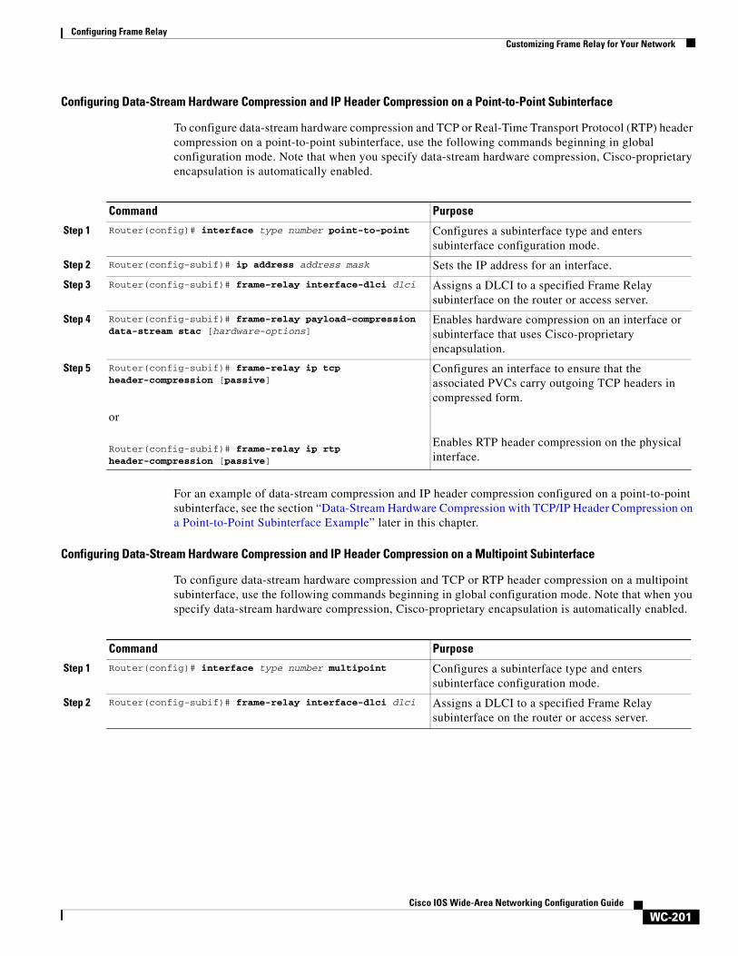
Configuring Frame RelayCustomizing Frame Relay for Your Network
WC-201Cisco IOS Wide-Area Networking Configuration Guide
Configuring Data-Stream Hardware Compression and IP Header Compression on a Point-to-Point Subinterface
To configure data-stream hardware compression and TCP or Real-Time Transport Protocol (RTP) header compression on a point-to-point subinterface, use the following commands beginning in global configuration mode. Note that when you specify data-stream hardware compression, Cisco-proprietary encapsulation is automatically enabled.
For an example of data-stream compression and IP header compression configured on a point-to-point subinterface, see the section “Data-Stream Hardware Compression with TCP/IP Header Compression on a Point-to-Point Subinterface Example” later in this chapter.
Configuring Data-Stream Hardware Compression and IP Header Compression on a Multipoint Subinterface
To configure data-stream hardware compression and TCP or RTP header compression on a multipoint subinterface, use the following commands beginning in global configuration mode. Note that when you specify data-stream hardware compression, Cisco-proprietary encapsulation is automatically enabled.
Command Purpose
Step 1 Router(config)# interface type number point-to-point Configures a subinterface type and enters subinterface configuration mode.
Step 2 Router(config-subif)# ip address address mask Sets the IP address for an interface.
Step 3 Router(config-subif)# frame-relay interface-dlci dlci Assigns a DLCI to a specified Frame Relay subinterface on the router or access server.
Step 4 Router(config-subif)# frame-relay payload-compression data-stream stac [hardware-options]
Enables hardware compression on an interface or subinterface that uses Cisco-proprietary encapsulation.
Step 5 Router(config-subif)# frame-relay ip tcp header-compression [passive]
or
Router(config-subif)# frame-relay ip rtp header-compression [passive]
Configures an interface to ensure that the associated PVCs carry outgoing TCP headers in compressed form.
Enables RTP header compression on the physical interface.
Command Purpose
Step 1 Router(config)# interface type number multipoint Configures a subinterface type and enters subinterface configuration mode.
Step 2 Router(config-subif)# frame-relay interface-dlci dlci Assigns a DLCI to a specified Frame Relay subinterface on the router or access server.
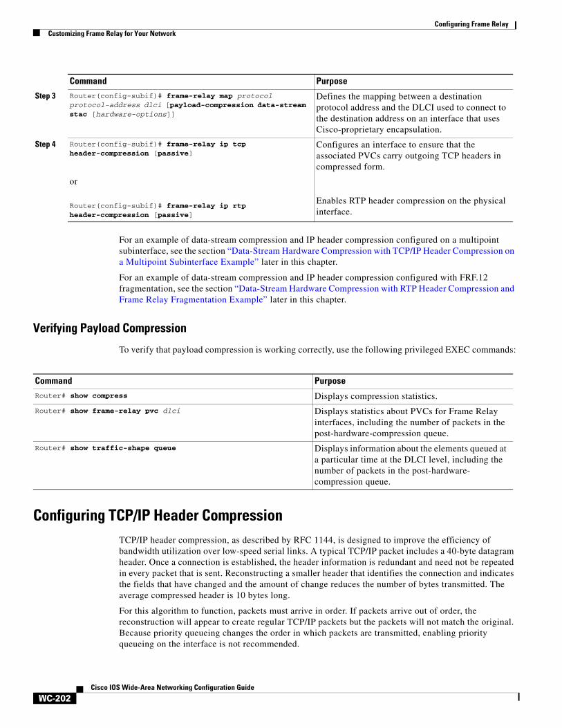
Configuring Frame RelayCustomizing Frame Relay for Your Network
WC-202Cisco IOS Wide-Area Networking Configuration Guide
For an example of data-stream compression and IP header compression configured on a multipoint subinterface, see the section “Data-Stream Hardware Compression with TCP/IP Header Compression on a Multipoint Subinterface Example” later in this chapter.
For an example of data-stream compression and IP header compression configured with FRF.12 fragmentation, see the section “Data-Stream Hardware Compression with RTP Header Compression and Frame Relay Fragmentation Example” later in this chapter.
Verifying Payload Compression
To verify that payload compression is working correctly, use the following privileged EXEC commands:
Configuring TCP/IP Header Compression TCP/IP header compression, as described by RFC 1144, is designed to improve the efficiency of bandwidth utilization over low-speed serial links. A typical TCP/IP packet includes a 40-byte datagram header. Once a connection is established, the header information is redundant and need not be repeated in every packet that is sent. Reconstructing a smaller header that identifies the connection and indicates the fields that have changed and the amount of change reduces the number of bytes transmitted. The average compressed header is 10 bytes long.
For this algorithm to function, packets must arrive in order. If packets arrive out of order, the reconstruction will appear to create regular TCP/IP packets but the packets will not match the original. Because priority queueing changes the order in which packets are transmitted, enabling priority queueing on the interface is not recommended.
Step 3 Router(config-subif)# frame-relay map protocol protocol-address dlci [payload-compression data-stream stac [hardware-options]]
Defines the mapping between a destination protocol address and the DLCI used to connect to the destination address on an interface that uses Cisco-proprietary encapsulation.
Step 4 Router(config-subif)# frame-relay ip tcp header-compression [passive]
or
Router(config-subif)# frame-relay ip rtp header-compression [passive]
Configures an interface to ensure that the associated PVCs carry outgoing TCP headers in compressed form.
Enables RTP header compression on the physical interface.
Command Purpose
Command Purpose
Router# show compress Displays compression statistics.
Router# show frame-relay pvc dlci Displays statistics about PVCs for Frame Relay interfaces, including the number of packets in the post-hardware-compression queue.
Router# show traffic-shape queue Displays information about the elements queued at a particular time at the DLCI level, including the number of packets in the post-hardware- compression queue.
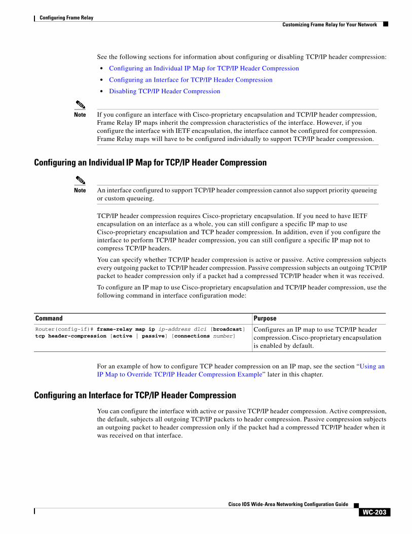
Configuring Frame RelayCustomizing Frame Relay for Your Network
WC-203Cisco IOS Wide-Area Networking Configuration Guide
See the following sections for information about configuring or disabling TCP/IP header compression:
• Configuring an Individual IP Map for TCP/IP Header Compression
• Configuring an Interface for TCP/IP Header Compression
• Disabling TCP/IP Header Compression
Note If you configure an interface with Cisco-proprietary encapsulation and TCP/IP header compression, Frame Relay IP maps inherit the compression characteristics of the interface. However, if you configure the interface with IETF encapsulation, the interface cannot be configured for compression. Frame Relay maps will have to be configured individually to support TCP/IP header compression.
Configuring an Individual IP Map for TCP/IP Header Compression
Note An interface configured to support TCP/IP header compression cannot also support priority queueing or custom queueing.
TCP/IP header compression requires Cisco-proprietary encapsulation. If you need to have IETF encapsulation on an interface as a whole, you can still configure a specific IP map to use Cisco-proprietary encapsulation and TCP header compression. In addition, even if you configure the interface to perform TCP/IP header compression, you can still configure a specific IP map not to compress TCP/IP headers.
You can specify whether TCP/IP header compression is active or passive. Active compression subjects every outgoing packet to TCP/IP header compression. Passive compression subjects an outgoing TCP/IP packet to header compression only if a packet had a compressed TCP/IP header when it was received.
To configure an IP map to use Cisco-proprietary encapsulation and TCP/IP header compression, use the following command in interface configuration mode:
For an example of how to configure TCP header compression on an IP map, see the section “Using an IP Map to Override TCP/IP Header Compression Example” later in this chapter.
Configuring an Interface for TCP/IP Header Compression
You can configure the interface with active or passive TCP/IP header compression. Active compression, the default, subjects all outgoing TCP/IP packets to header compression. Passive compression subjects an outgoing packet to header compression only if the packet had a compressed TCP/IP header when it was received on that interface.
Command Purpose
Router(config-if)# frame-relay map ip ip-address dlci [broadcast] tcp header-compression [active | passive] [connections number]
Configures an IP map to use TCP/IP header compression. Cisco-proprietary encapsulation is enabled by default.
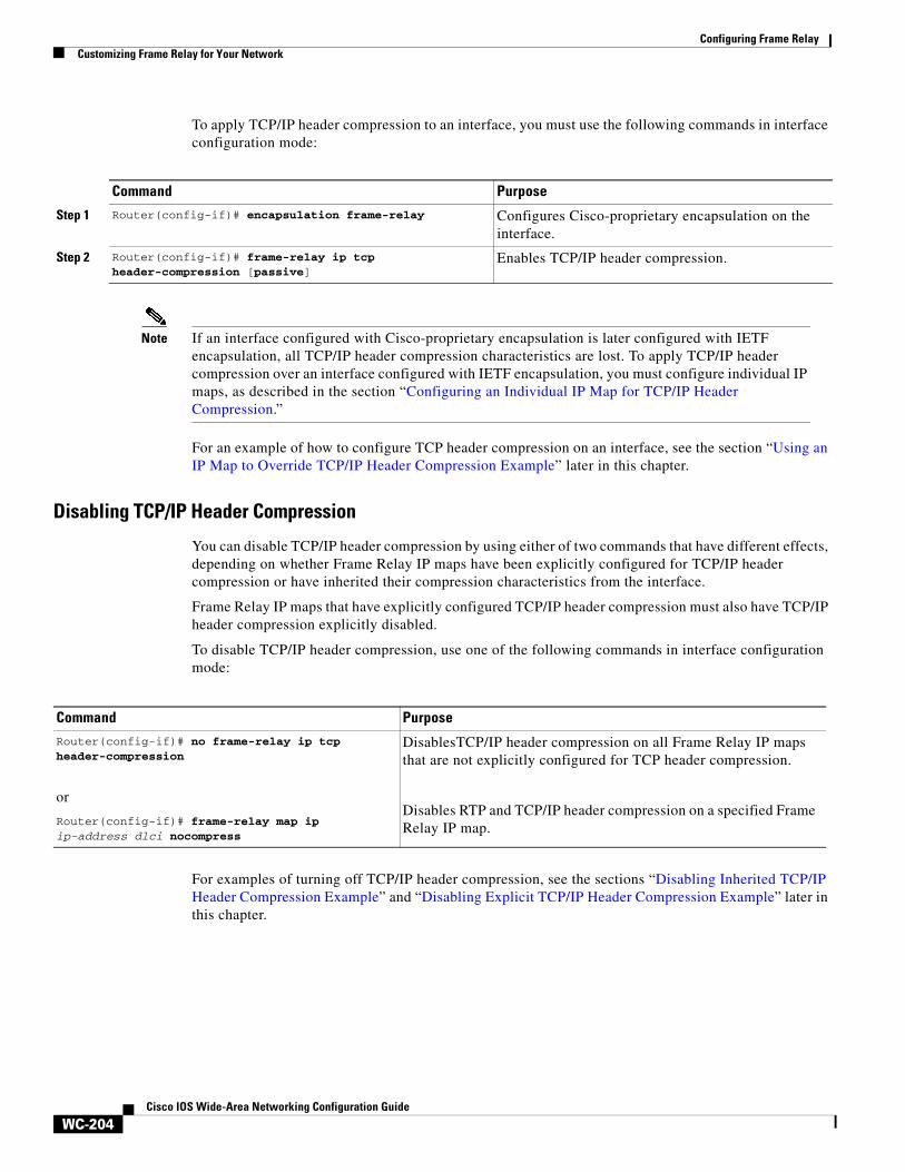
Configuring Frame RelayCustomizing Frame Relay for Your Network
WC-204Cisco IOS Wide-Area Networking Configuration Guide
To apply TCP/IP header compression to an interface, you must use the following commands in interface configuration mode:
Note If an interface configured with Cisco-proprietary encapsulation is later configured with IETF encapsulation, all TCP/IP header compression characteristics are lost. To apply TCP/IP header compression over an interface configured with IETF encapsulation, you must configure individual IP maps, as described in the section “Configuring an Individual IP Map for TCP/IP Header Compression.”
For an example of how to configure TCP header compression on an interface, see the section “Using an IP Map to Override TCP/IP Header Compression Example” later in this chapter.
Disabling TCP/IP Header Compression
You can disable TCP/IP header compression by using either of two commands that have different effects, depending on whether Frame Relay IP maps have been explicitly configured for TCP/IP header compression or have inherited their compression characteristics from the interface.
Frame Relay IP maps that have explicitly configured TCP/IP header compression must also have TCP/IP header compression explicitly disabled.
To disable TCP/IP header compression, use one of the following commands in interface configuration mode:
For examples of turning off TCP/IP header compression, see the sections “Disabling Inherited TCP/IP Header Compression Example” and “Disabling Explicit TCP/IP Header Compression Example” later in this chapter.
Command Purpose
Step 1 Router(config-if)# encapsulation frame-relay Configures Cisco-proprietary encapsulation on the interface.
Step 2 Router(config-if)# frame-relay ip tcp header-compression [passive]
Enables TCP/IP header compression.
Command Purpose
Router(config-if)# no frame-relay ip tcp header-compression
or
Router(config-if)# frame-relay map ip ip-address dlci nocompress
DisablesTCP/IP header compression on all Frame Relay IP maps that are not explicitly configured for TCP header compression.
Disables RTP and TCP/IP header compression on a specified Frame Relay IP map.
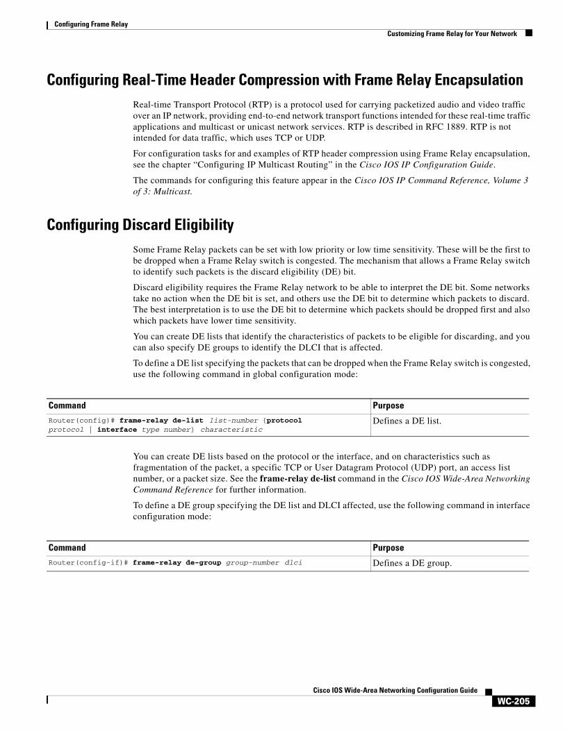
Configuring Frame RelayCustomizing Frame Relay for Your Network
WC-205Cisco IOS Wide-Area Networking Configuration Guide
Configuring Real-Time Header Compression with Frame Relay EncapsulationReal-time Transport Protocol (RTP) is a protocol used for carrying packetized audio and video traffic over an IP network, providing end-to-end network transport functions intended for these real-time traffic applications and multicast or unicast network services. RTP is described in RFC 1889. RTP is not intended for data traffic, which uses TCP or UDP.
For configuration tasks for and examples of RTP header compression using Frame Relay encapsulation, see the chapter “Configuring IP Multicast Routing” in the Cisco IOS IP Configuration Guide.
The commands for configuring this feature appear in the Cisco IOS IP Command Reference, Volume 3 of 3: Multicast.
Configuring Discard EligibilitySome Frame Relay packets can be set with low priority or low time sensitivity. These will be the first to be dropped when a Frame Relay switch is congested. The mechanism that allows a Frame Relay switch to identify such packets is the discard eligibility (DE) bit.
Discard eligibility requires the Frame Relay network to be able to interpret the DE bit. Some networks take no action when the DE bit is set, and others use the DE bit to determine which packets to discard. The best interpretation is to use the DE bit to determine which packets should be dropped first and also which packets have lower time sensitivity.
You can create DE lists that identify the characteristics of packets to be eligible for discarding, and you can also specify DE groups to identify the DLCI that is affected.
To define a DE list specifying the packets that can be dropped when the Frame Relay switch is congested, use the following command in global configuration mode:
You can create DE lists based on the protocol or the interface, and on characteristics such as fragmentation of the packet, a specific TCP or User Datagram Protocol (UDP) port, an access list number, or a packet size. See the frame-relay de-list command in the Cisco IOS Wide-Area Networking Command Reference for further information.
To define a DE group specifying the DE list and DLCI affected, use the following command in interface configuration mode:
Command Purpose
Router(config)# frame-relay de-list list-number {protocol protocol | interface type number} characteristic
Defines a DE list.
Command PurposeRouter(config-if)# frame-relay de-group group-number dlci Defines a DE group.
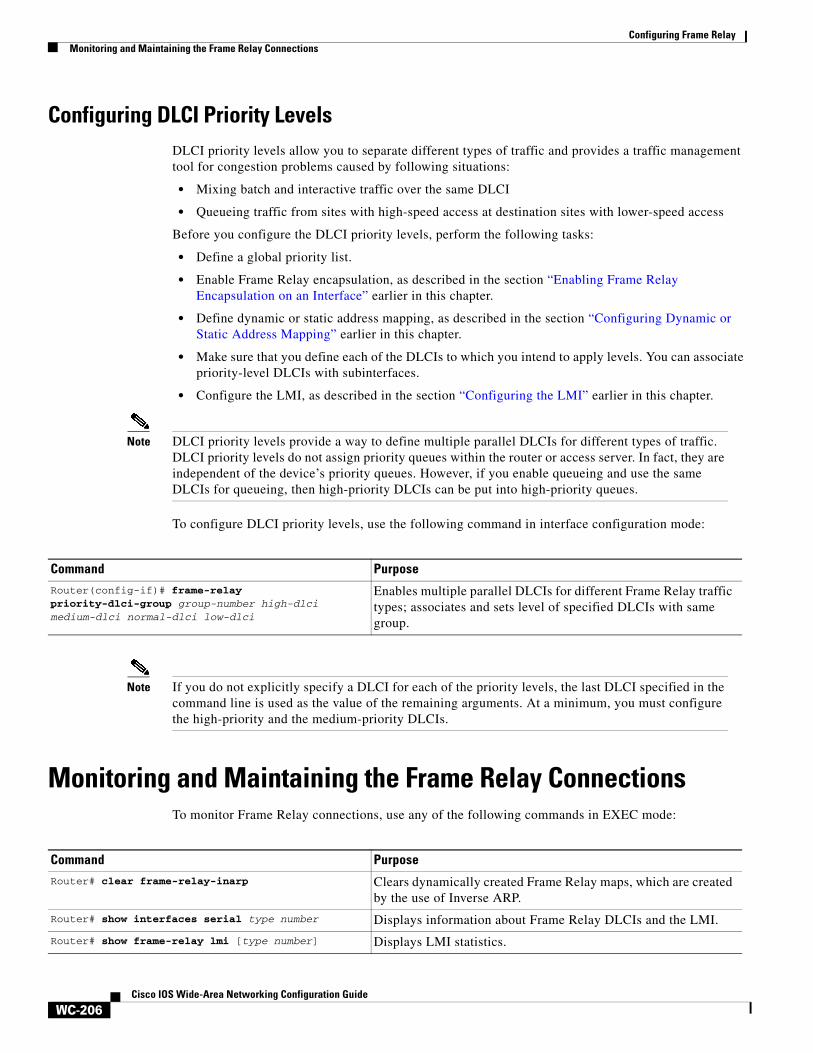
Configuring Frame RelayMonitoring and Maintaining the Frame Relay Connections
WC-206Cisco IOS Wide-Area Networking Configuration Guide
Configuring DLCI Priority Levels DLCI priority levels allow you to separate different types of traffic and provides a traffic management tool for congestion problems caused by following situations:
• Mixing batch and interactive traffic over the same DLCI
• Queueing traffic from sites with high-speed access at destination sites with lower-speed access
Before you configure the DLCI priority levels, perform the following tasks:
• Define a global priority list.
• Enable Frame Relay encapsulation, as described in the section “Enabling Frame Relay Encapsulation on an Interface” earlier in this chapter.
• Define dynamic or static address mapping, as described in the section “Configuring Dynamic or Static Address Mapping” earlier in this chapter.
• Make sure that you define each of the DLCIs to which you intend to apply levels. You can associate priority-level DLCIs with subinterfaces.
• Configure the LMI, as described in the section “Configuring the LMI” earlier in this chapter.
Note DLCI priority levels provide a way to define multiple parallel DLCIs for different types of traffic. DLCI priority levels do not assign priority queues within the router or access server. In fact, they are independent of the device’s priority queues. However, if you enable queueing and use the same DLCIs for queueing, then high-priority DLCIs can be put into high-priority queues.
To configure DLCI priority levels, use the following command in interface configuration mode:
Note If you do not explicitly specify a DLCI for each of the priority levels, the last DLCI specified in the command line is used as the value of the remaining arguments. At a minimum, you must configure the high-priority and the medium-priority DLCIs.
Monitoring and Maintaining the Frame Relay Connections To monitor Frame Relay connections, use any of the following commands in EXEC mode:
Command Purpose
Router(config-if)# frame-relay priority-dlci-group group-number high-dlci medium-dlci normal-dlci low-dlci
Enables multiple parallel DLCIs for different Frame Relay traffic types; associates and sets level of specified DLCIs with same group.
Command PurposeRouter# clear frame-relay-inarp Clears dynamically created Frame Relay maps, which are created
by the use of Inverse ARP.
Router# show interfaces serial type number Displays information about Frame Relay DLCIs and the LMI.
Router# show frame-relay lmi [type number] Displays LMI statistics.
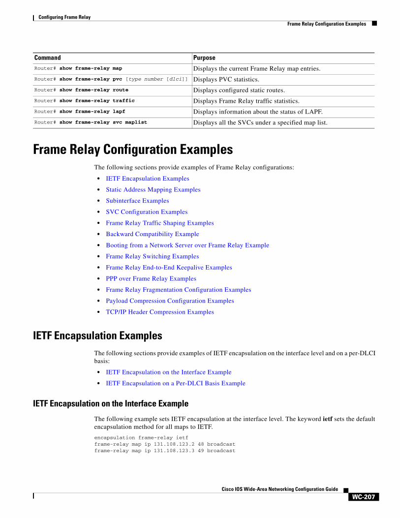
Configuring Frame RelayFrame Relay Configuration Examples
WC-207Cisco IOS Wide-Area Networking Configuration Guide
Frame Relay Configuration Examples The following sections provide examples of Frame Relay configurations:
• IETF Encapsulation Examples
• Static Address Mapping Examples
• Subinterface Examples
• SVC Configuration Examples
• Frame Relay Traffic Shaping Examples
• Backward Compatibility Example
• Booting from a Network Server over Frame Relay Example
• Frame Relay Switching Examples
• Frame Relay End-to-End Keepalive Examples
• PPP over Frame Relay Examples
• Frame Relay Fragmentation Configuration Examples
• Payload Compression Configuration Examples
• TCP/IP Header Compression Examples
IETF Encapsulation Examples The following sections provide examples of IETF encapsulation on the interface level and on a per-DLCI basis:
• IETF Encapsulation on the Interface Example
• IETF Encapsulation on a Per-DLCI Basis Example
IETF Encapsulation on the Interface Example
The following example sets IETF encapsulation at the interface level. The keyword ietf sets the default encapsulation method for all maps to IETF.
encapsulation frame-relay ietfframe-relay map ip 131.108.123.2 48 broadcastframe-relay map ip 131.108.123.3 49 broadcast
Router# show frame-relay map Displays the current Frame Relay map entries.
Router# show frame-relay pvc [type number [dlci]] Displays PVC statistics.
Router# show frame-relay route Displays configured static routes.
Router# show frame-relay traffic Displays Frame Relay traffic statistics.
Router# show frame-relay lapf Displays information about the status of LAPF.
Router# show frame-relay svc maplist Displays all the SVCs under a specified map list.
Command Purpose
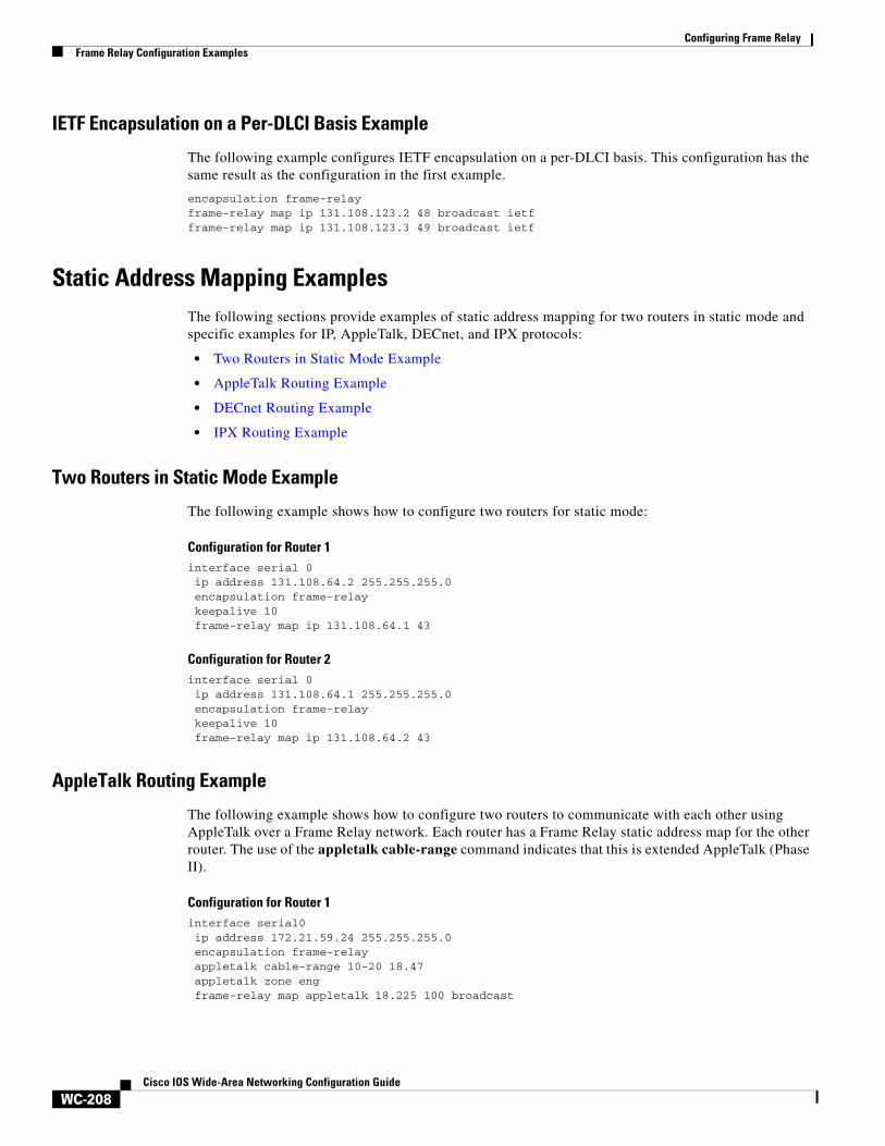
Configuring Frame RelayFrame Relay Configuration Examples
WC-208Cisco IOS Wide-Area Networking Configuration Guide
IETF Encapsulation on a Per-DLCI Basis Example
The following example configures IETF encapsulation on a per-DLCI basis. This configuration has the same result as the configuration in the first example.
encapsulation frame-relay frame-relay map ip 131.108.123.2 48 broadcast ietfframe-relay map ip 131.108.123.3 49 broadcast ietf
Static Address Mapping ExamplesThe following sections provide examples of static address mapping for two routers in static mode and specific examples for IP, AppleTalk, DECnet, and IPX protocols:
• Two Routers in Static Mode Example
• AppleTalk Routing Example
• DECnet Routing Example
• IPX Routing Example
Two Routers in Static Mode Example
The following example shows how to configure two routers for static mode:
Configuration for Router 1interface serial 0ip address 131.108.64.2 255.255.255.0encapsulation frame-relaykeepalive 10frame-relay map ip 131.108.64.1 43
Configuration for Router 2interface serial 0ip address 131.108.64.1 255.255.255.0encapsulation frame-relaykeepalive 10frame-relay map ip 131.108.64.2 43
AppleTalk Routing Example
The following example shows how to configure two routers to communicate with each other using AppleTalk over a Frame Relay network. Each router has a Frame Relay static address map for the other router. The use of the appletalk cable-range command indicates that this is extended AppleTalk (Phase II).
Configuration for Router 1interface serial0ip address 172.21.59.24 255.255.255.0encapsulation frame-relayappletalk cable-range 10-20 18.47appletalk zone engframe-relay map appletalk 18.225 100 broadcast
Configuring Frame RelayFrame Relay Configuration Examples
WC-209Cisco IOS Wide-Area Networking Configuration Guide
Configuration for Router 2interface serial2/3ip address 172.21.177.18 255.255.255.0encapsulation frame-relayappletalk cable-range 10-20 18.225appletalk zone engclockrate 2000000frame-relay map appletalk 18.47 100 broadcast
DECnet Routing Example
The following example sends all DECnet packets destined for address 56.4 out on DLCI 101. In addition, any DECnet broadcasts for interface serial 1 will be sent on that DLCI.
decnet routing 32.6!interface serial 1encapsulation frame-relayframe-relay map decnet 56.4 101 broadcast
IPX Routing Example
The following example shows how to send packets destined for IPX address 200.0000.0c00.7b21 out on DLCI 102:
ipx routing 000.0c00.7b3b!interface ethernet 0ipx network 2abc
!interface serial 0ipx network 200encapsulation frame-relayframe-relay map ipx 200.0000.0c00.7b21 102 broadcast
Subinterface Examples The following sections provide Frame Relay subinterface examples and variations appropriate for different routed protocols and bridging:
• Basic Subinterface Example
• Frame Relay Multipoint Subinterface with Dynamic Addressing Example
• IPX Routes over Frame Relay Subinterfaces Example
• Unnumbered IP over a Point-to-Point Subinterface Example
• Transparent Bridging Using Subinterfaces Example
Basic Subinterface Example
In the following example, subinterface 1 is configured as a point-to-point subnet and subinterface 2 is configured as a multipoint subnet.
interface serial 0encapsulation frame-relay
interface serial 0.1 point-to-pointip address 10.0.1.1 255.255.255.0
Configuring Frame RelayFrame Relay Configuration Examples
WC-210Cisco IOS Wide-Area Networking Configuration Guide
frame-relay interface-dlci 42!interface serial 0.2 multipointip address 10.0.2.1 255.255.255.0frame-relay map ip 10.0.2.2 18
Frame Relay Multipoint Subinterface with Dynamic Addressing Example
The following example configures two multipoint subinterfaces for dynamic address resolution. Each subinterface is provided with an individual protocol address and subnet mask, and the frame-relay interface-dlci command associates the subinterface with a specified DLCI. Addresses of remote destinations for each multipoint subinterface will be resolved dynamically.
interface serial0 no ip address encapsulation frame-relay frame-relay lmi-type ansi!interface serial0.103 multipoint ip address 172.21.177.18 255.255.255.0 frame-relay interface-dlci 300!interface serial0.104 multipoint ip address 172.21.178.18 255.255.255.0 frame-relay interface-dlci 400
IPX Routes over Frame Relay Subinterfaces Example
The following example configures a serial interface for Frame Relay encapsulation and sets up multiple IPX virtual networks corresponding to Frame Relay subinterfaces:
ipx routing 0000.0c02.5f4f!interface serial 0encapsulation frame-relayinterface serial 0.1 multipointipx network 1frame-relay map ipx 1.000.0c07.d530 200 broadcastinterface serial 0.2 multipointipx network 2frame-relay map ipx 2.000.0c07.d530 300 broadcast
For subinterface serial 0.1, the router at the other end might be configured as follows:
ipx routing interface serial 2 multipointipx network 1frame-relay map ipx 1.000.0c02.5f4f 200 broadcast
Unnumbered IP over a Point-to-Point Subinterface Example
The following example sets up unnumbered IP over subinterfaces at both ends of a point-to-point connection. In this example, router A functions as the DTE, and router B functions as the DCE. Routers A and B are both attached to Token Ring networks.
Configuration for Router Ainterface token-ring 0ip address 131.108.177.1 255.255.255.0
!
Configuring Frame RelayFrame Relay Configuration Examples
WC-211Cisco IOS Wide-Area Networking Configuration Guide
interface serial 0no ip addressencapsulation frame-relay IETF
!interface serial0.2 point-to-pointip unnumbered TokenRing0ip pim sparse-modeframe-relay interface-dlci 20
Configuration for Router Bframe-relay switching!interface token-ring 0ip address 131.108.178.1 255.255.255.0
!interface serial 0no ip addressencapsulation frame-relay IETFbandwidth 384clockrate 4000000frame-relay intf-type dce
!interface serial 0.2 point-to-pointip unnumbered TokenRing1ip pim sparse-mode
!bandwidth 384frame-relay interface-dlci 20
Transparent Bridging Using Subinterfaces Example
The following example shows Frame Relay DLCIs 42, 64, and 73 as separate point-to-point links with transparent bridging running over them. The bridging spanning tree views each PVC as a separate bridge port, and a frame arriving on the PVC can be relayed back out on a separate PVC.
interface serial 0encapsulation frame-relay
interface serial 0.1 point-to-pointbridge-group 1frame-relay interface-dlci 42
interface serial 0.2 point-to-pointbridge-group 1frame-relay interface-dlci 64
interface serial 0.3 point-to-pointbridge-group 1frame-relay interface-dlci 73
SVC Configuration Examples The following sections provide examples of Frame Relay SVC configuration for interfaces and subinterfaces:
• SVC Interface Example
• SVC Subinterface Example
Configuring Frame RelayFrame Relay Configuration Examples
WC-212Cisco IOS Wide-Area Networking Configuration Guide
SVC Interface Example
The following example configures a physical interface, applies a map group to the physical interface, and then defines the map group:
interface serial 0ip address 172.10.8.6encapsulation frame-relaymap-group bermudaframe-relay lmi-type q933aframe-relay svc
!map-list bermuda source-addr E164 123456 dest-addr E164 654321ip 131.108.177.100 class hawaiiappletalk 1000.2 class rainbow
!map-class frame-relay rainbowframe-relay idle-timer 60
!map-class frame-relay hawaiiframe-relay cir in 64000frame-relay cir out 64000
SVC Subinterface Example
The following example configures a point-to-point interface for SVC operation. It assumes that the main serial 0 interface has been configured for signalling and that SVC operation has been enabled on the main interface:
int s 0.1 point-point! Define the map-group; details are specified under the map-list holiday command.map-group holiday!! Associate the map-group with a specific source and destination.map-list holiday local-addr X121 <X121-addr> dest-addr E164 <E164-addr>! Specify destination protocol addresses for a map-class.ip 131.108.177.100 class hawaii IETFappletalk 1000.2 class rainbow IETF broadcast
!! Define a map class and its QoS settings.map-class hawaiiframe-relay cir in 2000000frame-relay cir out 56000frame-relay be 9000
!! Define another map class and its QoS settings.map-class rainbowframe-relay cir in 64000frame-relay idle-timer 2000
Frame Relay Traffic Shaping Examples The following sections provide examples of Frame Relay traffic shaping:
• Traffic Shaping with Three Point-to-Point Subinterfaces Example
• Traffic Shaping with ForeSight Example
• ELMI Configuration Examples
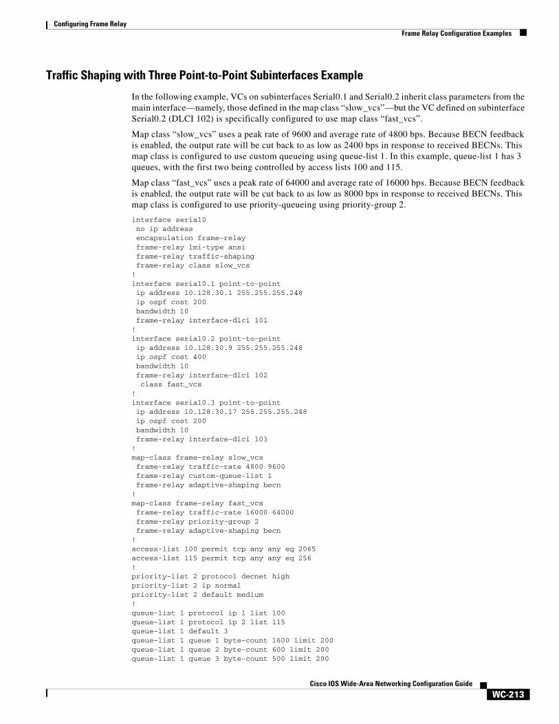
Configuring Frame RelayFrame Relay Configuration Examples
WC-213Cisco IOS Wide-Area Networking Configuration Guide
Traffic Shaping with Three Point-to-Point Subinterfaces Example
In the following example, VCs on subinterfaces Serial0.1 and Serial0.2 inherit class parameters from the main interface—namely, those defined in the map class “slow_vcs”—but the VC defined on subinterface Serial0.2 (DLCI 102) is specifically configured to use map class “fast_vcs”.
Map class “slow_vcs” uses a peak rate of 9600 and average rate of 4800 bps. Because BECN feedback is enabled, the output rate will be cut back to as low as 2400 bps in response to received BECNs. This map class is configured to use custom queueing using queue-list 1. In this example, queue-list 1 has 3 queues, with the first two being controlled by access lists 100 and 115.
Map class “fast_vcs” uses a peak rate of 64000 and average rate of 16000 bps. Because BECN feedback is enabled, the output rate will be cut back to as low as 8000 bps in response to received BECNs. This map class is configured to use priority-queueing using priority-group 2.
interface serial0no ip addressencapsulation frame-relayframe-relay lmi-type ansiframe-relay traffic-shapingframe-relay class slow_vcs
!interface serial0.1 point-to-pointip address 10.128.30.1 255.255.255.248ip ospf cost 200bandwidth 10frame-relay interface-dlci 101
!interface serial0.2 point-to-pointip address 10.128.30.9 255.255.255.248ip ospf cost 400bandwidth 10frame-relay interface-dlci 102class fast_vcs
!interface serial0.3 point-to-pointip address 10.128.30.17 255.255.255.248ip ospf cost 200bandwidth 10frame-relay interface-dlci 103
!map-class frame-relay slow_vcsframe-relay traffic-rate 4800 9600frame-relay custom-queue-list 1frame-relay adaptive-shaping becn
!map-class frame-relay fast_vcsframe-relay traffic-rate 16000 64000frame-relay priority-group 2frame-relay adaptive-shaping becn
!access-list 100 permit tcp any any eq 2065access-list 115 permit tcp any any eq 256!priority-list 2 protocol decnet highpriority-list 2 ip normalpriority-list 2 default medium!queue-list 1 protocol ip 1 list 100queue-list 1 protocol ip 2 list 115queue-list 1 default 3queue-list 1 queue 1 byte-count 1600 limit 200queue-list 1 queue 2 byte-count 600 limit 200queue-list 1 queue 3 byte-count 500 limit 200
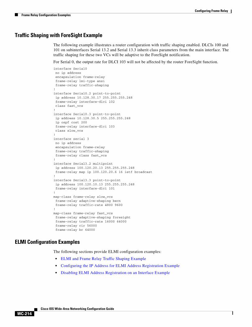
Configuring Frame RelayFrame Relay Configuration Examples
WC-214Cisco IOS Wide-Area Networking Configuration Guide
Traffic Shaping with ForeSight Example
The following example illustrates a router configuration with traffic shaping enabled. DLCIs 100 and 101 on subinterfaces Serial 13.2 and Serial 13.3 inherit class parameters from the main interface. The traffic shaping for these two VCs will be adaptive to the ForeSight notification.
For Serial 0, the output rate for DLCI 103 will not be affected by the router ForeSight function.
interface Serial0no ip addressencapsulation frame-relayframe-relay lmi-type ansiframe-relay traffic-shaping
!interface Serial0.2 point-to-pointip address 10.128.30.17 255.255.255.248frame-relay interface-dlci 102class fast_vcs
!interface Serial0.3 point-to-pointip address 10.128.30.5 255.255.255.248ip ospf cost 200frame-relay interface-dlci 103class slow_vcs
!interface serial 3no ip addressencapsulation frame-relayframe-relay traffic-shapingframe-relay class fast_vcs
!interface Serial3.2 multipointip address 100.120.20.13 255.255.255.248frame-relay map ip 100.120.20.6 16 ietf broadcast
!interface Serial3.3 point-to-pointip address 100.120.10.13 255.255.255.248frame-relay interface-dlci 101
!map-class frame-relay slow_vcsframe-relay adaptive-shaping becnframe-relay traffic-rate 4800 9600
!map-class frame-relay fast_vcsframe-relay adaptive-shaping foresightframe-relay traffic-rate 16000 64000frame-relay cir 56000frame-relay bc 64000
ELMI Configuration Examples
The following sections provide ELMI configuration examples:
• ELMI and Frame Relay Traffic Shaping Example
• Configuring the IP Address for ELMI Address Registration Example
• Disabling ELMI Address Registration on an Interface Example
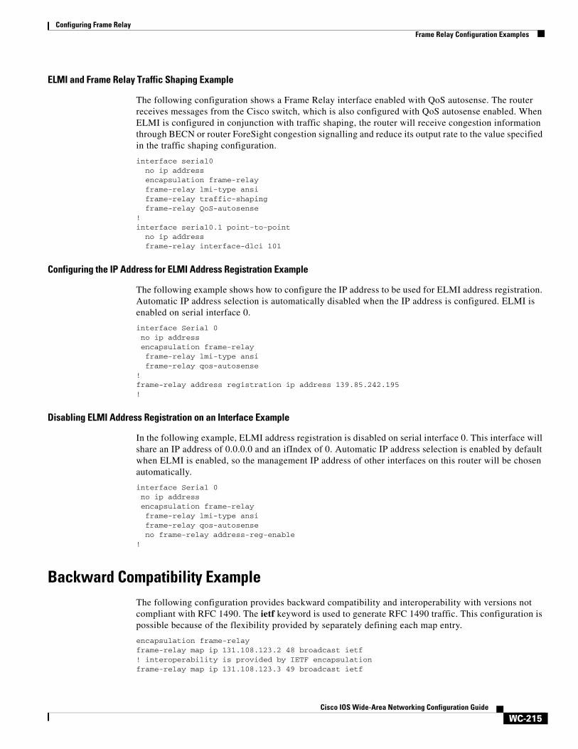
Configuring Frame RelayFrame Relay Configuration Examples
WC-215Cisco IOS Wide-Area Networking Configuration Guide
ELMI and Frame Relay Traffic Shaping Example
The following configuration shows a Frame Relay interface enabled with QoS autosense. The router receives messages from the Cisco switch, which is also configured with QoS autosense enabled. When ELMI is configured in conjunction with traffic shaping, the router will receive congestion information through BECN or router ForeSight congestion signalling and reduce its output rate to the value specified in the traffic shaping configuration.
interface serial0 no ip address encapsulation frame-relay frame-relay lmi-type ansi frame-relay traffic-shaping frame-relay QoS-autosense
! interface serial0.1 point-to-point
no ip address frame-relay interface-dlci 101
Configuring the IP Address for ELMI Address Registration Example
The following example shows how to configure the IP address to be used for ELMI address registration. Automatic IP address selection is automatically disabled when the IP address is configured. ELMI is enabled on serial interface 0.
interface Serial 0 no ip address encapsulation frame-relay frame-relay lmi-type ansi frame-relay qos-autosense!frame-relay address registration ip address 139.85.242.195!
Disabling ELMI Address Registration on an Interface Example
In the following example, ELMI address registration is disabled on serial interface 0. This interface will share an IP address of 0.0.0.0 and an ifIndex of 0. Automatic IP address selection is enabled by default when ELMI is enabled, so the management IP address of other interfaces on this router will be chosen automatically.
interface Serial 0 no ip address encapsulation frame-relay frame-relay lmi-type ansi frame-relay qos-autosense no frame-relay address-reg-enable!
Backward Compatibility ExampleThe following configuration provides backward compatibility and interoperability with versions not compliant with RFC 1490. The ietf keyword is used to generate RFC 1490 traffic. This configuration is possible because of the flexibility provided by separately defining each map entry.
encapsulation frame-relayframe-relay map ip 131.108.123.2 48 broadcast ietf! interoperability is provided by IETF encapsulationframe-relay map ip 131.108.123.3 49 broadcast ietf
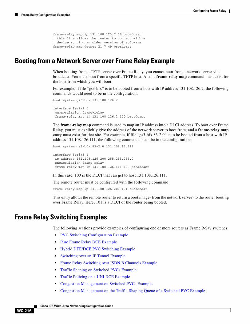
Configuring Frame RelayFrame Relay Configuration Examples
WC-216Cisco IOS Wide-Area Networking Configuration Guide
frame-relay map ip 131.108.123.7 58 broadcast ! this line allows the router to connect with a ! device running an older version of softwareframe-relay map decnet 21.7 49 broadcast
Booting from a Network Server over Frame Relay ExampleWhen booting from a TFTP server over Frame Relay, you cannot boot from a network server via a broadcast. You must boot from a specific TFTP host. Also, a frame-relay map command must exist for the host from which you will boot.
For example, if file “gs3-bfx” is to be booted from a host with IP address 131.108.126.2, the following commands would need to be in the configuration:
boot system gs3-bfx 131.108.126.2!interface Serial 0encapsulation frame-relayframe-relay map IP 131.108.126.2 100 broadcast
The frame-relay map command is used to map an IP address into a DLCI address. To boot over Frame Relay, you must explicitly give the address of the network server to boot from, and a frame-relay map entry must exist for that site. For example, if file “gs3-bfx.83-2.0” is to be booted from a host with IP address 131.108.126.111, the following commands must be in the configuration:
boot system gs3-bfx.83-2.0 131.108.13.111!interface Serial 1ip address 131.108.126.200 255.255.255.0encapsulation frame-relayframe-relay map ip 131.108.126.111 100 broadcast
In this case, 100 is the DLCI that can get to host 131.108.126.111.
The remote router must be configured with the following command:
frame-relay map ip 131.108.126.200 101 broadcast
This entry allows the remote router to return a boot image (from the network server) to the router booting over Frame Relay. Here, 101 is a DLCI of the router being booted.
Frame Relay Switching Examples The following sections provide examples of configuring one or more routers as Frame Relay switches:
• PVC Switching Configuration Example
• Pure Frame Relay DCE Example
• Hybrid DTE/DCE PVC Switching Example
• Switching over an IP Tunnel Example
• Frame Relay Switching over ISDN B Channels Example
• Traffic Shaping on Switched PVCs Example
• Traffic Policing on a UNI DCE Example
• Congestion Management on Switched PVCs Example
• Congestion Management on the Traffic-Shaping Queue of a Switched PVC Example
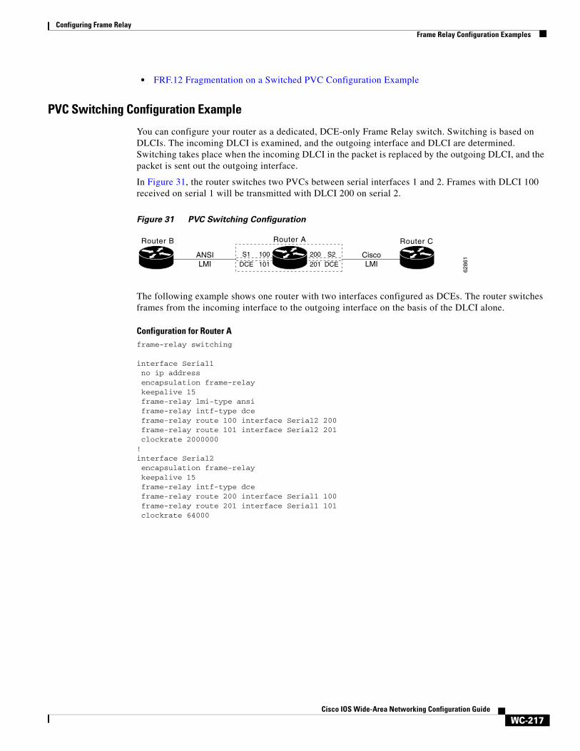
Configuring Frame RelayFrame Relay Configuration Examples
WC-217Cisco IOS Wide-Area Networking Configuration Guide
• FRF.12 Fragmentation on a Switched PVC Configuration Example
PVC Switching Configuration Example
You can configure your router as a dedicated, DCE-only Frame Relay switch. Switching is based on DLCIs. The incoming DLCI is examined, and the outgoing interface and DLCI are determined. Switching takes place when the incoming DLCI in the packet is replaced by the outgoing DLCI, and the packet is sent out the outgoing interface.
In Figure 31, the router switches two PVCs between serial interfaces 1 and 2. Frames with DLCI 100 received on serial 1 will be transmitted with DLCI 200 on serial 2.
Figure 31 PVC Switching Configuration
The following example shows one router with two interfaces configured as DCEs. The router switches frames from the incoming interface to the outgoing interface on the basis of the DLCI alone.
Configuration for Router Aframe-relay switching
interface Serial1no ip addressencapsulation frame-relaykeepalive 15frame-relay lmi-type ansiframe-relay intf-type dceframe-relay route 100 interface Serial2 200frame-relay route 101 interface Serial2 201clockrate 2000000
!interface Serial2encapsulation frame-relaykeepalive 15frame-relay intf-type dceframe-relay route 200 interface Serial1 100frame-relay route 201 interface Serial1 101clockrate 64000
Router B Router A
6286
1
Router C
ANSILMI
CiscoLMI
S1
DCE
S2
DCE
100
101
200
201
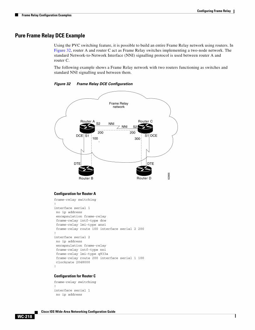
Configuring Frame RelayFrame Relay Configuration Examples
WC-218Cisco IOS Wide-Area Networking Configuration Guide
Pure Frame Relay DCE Example
Using the PVC switching feature, it is possible to build an entire Frame Relay network using routers. In Figure 32, router A and router C act as Frame Relay switches implementing a two-node network. The standard Network-to-Network Interface (NNI) signalling protocol is used between router A and router C.
The following example shows a Frame Relay network with two routers functioning as switches and standard NNI signalling used between them.
Figure 32 Frame Relay DCE Configuration
Configuration for Router Aframe-relay switching!interface serial 1no ip addressencapsulation frame-relayframe-relay intf-type dceframe-relay lmi-type ansiframe-relay route 100 interface serial 2 200
!interface serial 2no ip addressencapsulation frame-relayframe-relay intf-type nniframe-relay lmi-type q933aframe-relay route 200 interface serial 1 100clockrate 2048000
!
Configuration for Router Cframe-relay switching!interface serial 1no ip address
Router A Router C
Router B Router D 6286
6
NNINNI
Frame Relaynetwork
DTE DTE
DCE DCES1S1
S2S2
100 300
200200
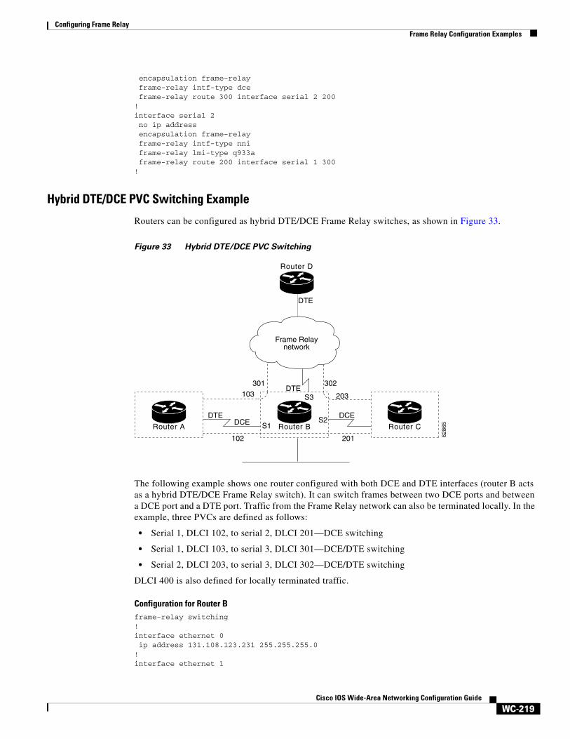
Configuring Frame RelayFrame Relay Configuration Examples
WC-219Cisco IOS Wide-Area Networking Configuration Guide
encapsulation frame-relayframe-relay intf-type dceframe-relay route 300 interface serial 2 200
!interface serial 2no ip addressencapsulation frame-relayframe-relay intf-type nniframe-relay lmi-type q933aframe-relay route 200 interface serial 1 300
!
Hybrid DTE/DCE PVC Switching Example
Routers can be configured as hybrid DTE/DCE Frame Relay switches, as shown in Figure 33.
Figure 33 Hybrid DTE/DCE PVC Switching
The following example shows one router configured with both DCE and DTE interfaces (router B acts as a hybrid DTE/DCE Frame Relay switch). It can switch frames between two DCE ports and between a DCE port and a DTE port. Traffic from the Frame Relay network can also be terminated locally. In the example, three PVCs are defined as follows:
• Serial 1, DLCI 102, to serial 2, DLCI 201—DCE switching
• Serial 1, DLCI 103, to serial 3, DLCI 301—DCE/DTE switching
• Serial 2, DLCI 203, to serial 3, DLCI 302—DCE/DTE switching
DLCI 400 is also defined for locally terminated traffic.
Configuration for Router Bframe-relay switching!interface ethernet 0ip address 131.108.123.231 255.255.255.0
!interface ethernet 1
Router D
Router B
6286
5
Frame Relaynetwork
DCEDTEDCE
DTE
DTE
102 201
301103
302
203
S1S2
S3
Router A Router C
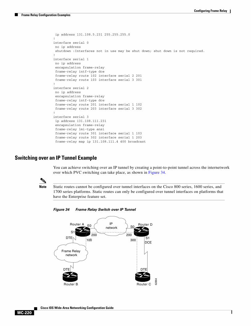
Configuring Frame RelayFrame Relay Configuration Examples
WC-220Cisco IOS Wide-Area Networking Configuration Guide
ip address 131.108.5.231 255.255.255.0!interface serial 0no ip addressshutdown :Interfaces not in use may be shut down; shut down is not required.
!interface serial 1no ip addressencapsulation frame-relayframe-relay intf-type dceframe-relay route 102 interface serial 2 201frame-relay route 103 interface serial 3 301
!interface serial 2no ip addressencapsulation frame-relayframe-relay intf-type dceframe-relay route 201 interface serial 1 102frame-relay route 203 interface serial 3 302
!interface serial 3ip address 131.108.111.231encapsulation frame-relayframe-relay lmi-type ansiframe-relay route 301 interface serial 1 103frame-relay route 302 interface serial 1 203frame-relay map ip 131.108.111.4 400 broadcast
Switching over an IP Tunnel Example
You can achieve switching over an IP tunnel by creating a point-to-point tunnel across the internetwork over which PVC switching can take place, as shown in Figure 34.
Note Static routes cannot be configured over tunnel interfaces on the Cisco 800 series, 1600 series, and 1700 series platforms. Static routes can only be configured over tunnel interfaces on platforms that have the Enterprise feature set.
Figure 34 Frame Relay Switch over IP Tunnel
Router A Router D
Router B Router C
IP network
Frame Relay network
6286
4
DTE
DTE DTE
DCE
E0 S0
S1
S1200
100
200
300
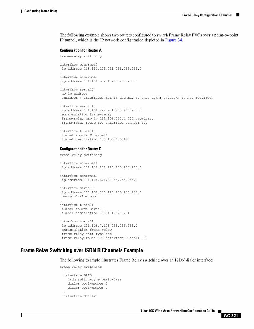
Configuring Frame RelayFrame Relay Configuration Examples
WC-221Cisco IOS Wide-Area Networking Configuration Guide
The following example shows two routers configured to switch Frame Relay PVCs over a point-to-point IP tunnel, which is the IP network configuration depicted in Figure 34.
Configuration for Router Aframe-relay switching!interface ethernet0ip address 108.131.123.231 255.255.255.0
!interface ethernet1ip address 131.108.5.231 255.255.255.0
!interface serial0no ip addressshutdown : Interfaces not in use may be shut down; shutdown is not required.
!interface serial1ip address 131.108.222.231 255.255.255.0encapsulation frame-relayframe-relay map ip 131.108.222.4 400 broadcastframe-relay route 100 interface Tunnel1 200
!interface tunnel1tunnel source Ethernet0tunnel destination 150.150.150.123
Configuration for Router Dframe-relay switching!interface ethernet0ip address 131.108.231.123 255.255.255.0
!interface ethernet1ip address 131.108.6.123 255.255.255.0
!interface serial0ip address 150.150.150.123 255.255.255.0encapsulation ppp
!interface tunnel1tunnel source Serial0tunnel destination 108.131.123.231
!interface serial1ip address 131.108.7.123 255.255.255.0encapsulation frame-relayframe-relay intf-type dceframe-relay route 300 interface Tunnel1 200
Frame Relay Switching over ISDN B Channels Example
The following example illustrates Frame Relay switching over an ISDN dialer interface:
frame-relay switching ! interface BRI0 isdn switch-type basic-5ess dialer pool-member 1 dialer pool-member 2 ! interface dialer1
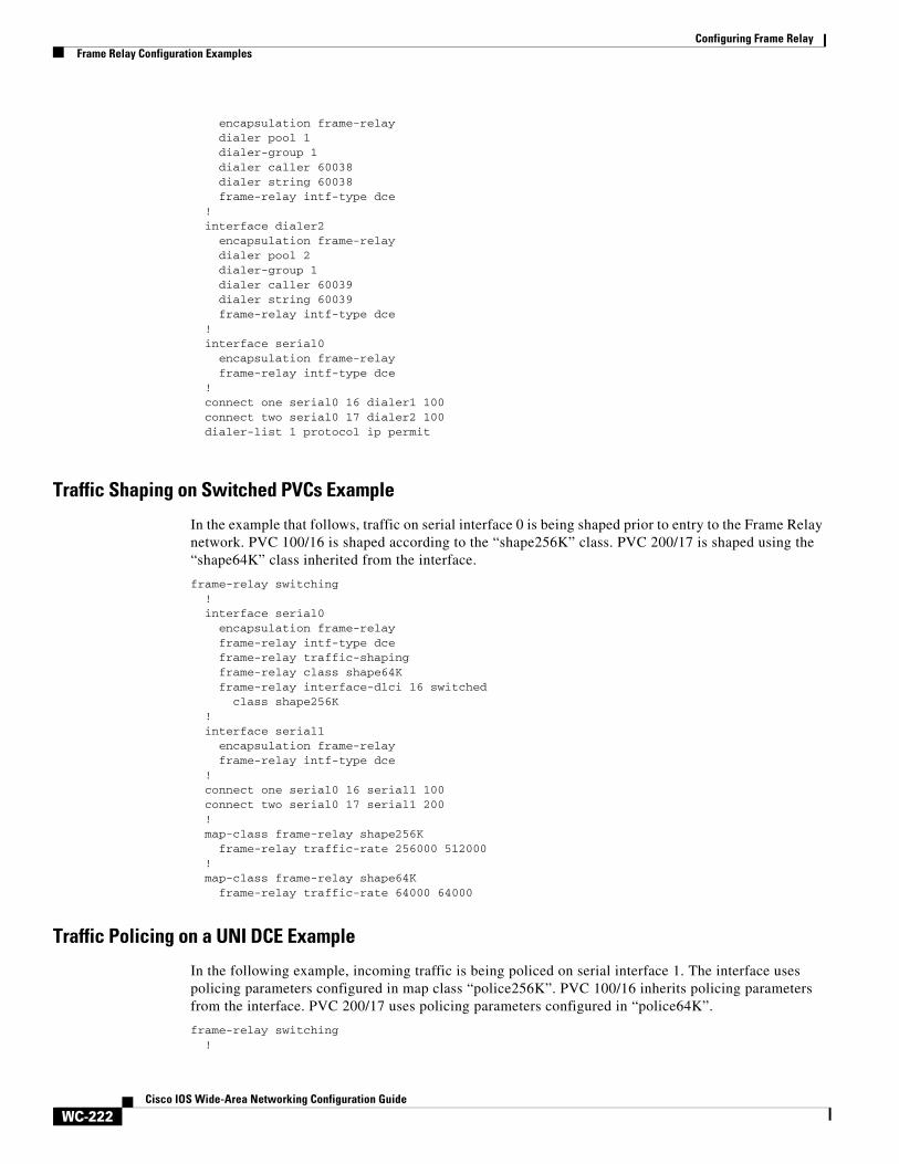
Configuring Frame RelayFrame Relay Configuration Examples
WC-222Cisco IOS Wide-Area Networking Configuration Guide
encapsulation frame-relay dialer pool 1 dialer-group 1 dialer caller 60038 dialer string 60038 frame-relay intf-type dce ! interface dialer2 encapsulation frame-relay dialer pool 2 dialer-group 1 dialer caller 60039 dialer string 60039 frame-relay intf-type dce ! interface serial0 encapsulation frame-relay frame-relay intf-type dce ! connect one serial0 16 dialer1 100 connect two serial0 17 dialer2 100 dialer-list 1 protocol ip permit
Traffic Shaping on Switched PVCs Example
In the example that follows, traffic on serial interface 0 is being shaped prior to entry to the Frame Relay network. PVC 100/16 is shaped according to the “shape256K” class. PVC 200/17 is shaped using the “shape64K” class inherited from the interface.
frame-relay switching ! interface serial0 encapsulation frame-relay frame-relay intf-type dce frame-relay traffic-shaping frame-relay class shape64K frame-relay interface-dlci 16 switched class shape256K ! interface serial1 encapsulation frame-relay frame-relay intf-type dce ! connect one serial0 16 serial1 100 connect two serial0 17 serial1 200 ! map-class frame-relay shape256K frame-relay traffic-rate 256000 512000 ! map-class frame-relay shape64K frame-relay traffic-rate 64000 64000
Traffic Policing on a UNI DCE Example
In the following example, incoming traffic is being policed on serial interface 1. The interface uses policing parameters configured in map class “police256K”. PVC 100/16 inherits policing parameters from the interface. PVC 200/17 uses policing parameters configured in “police64K”.
frame-relay switching !
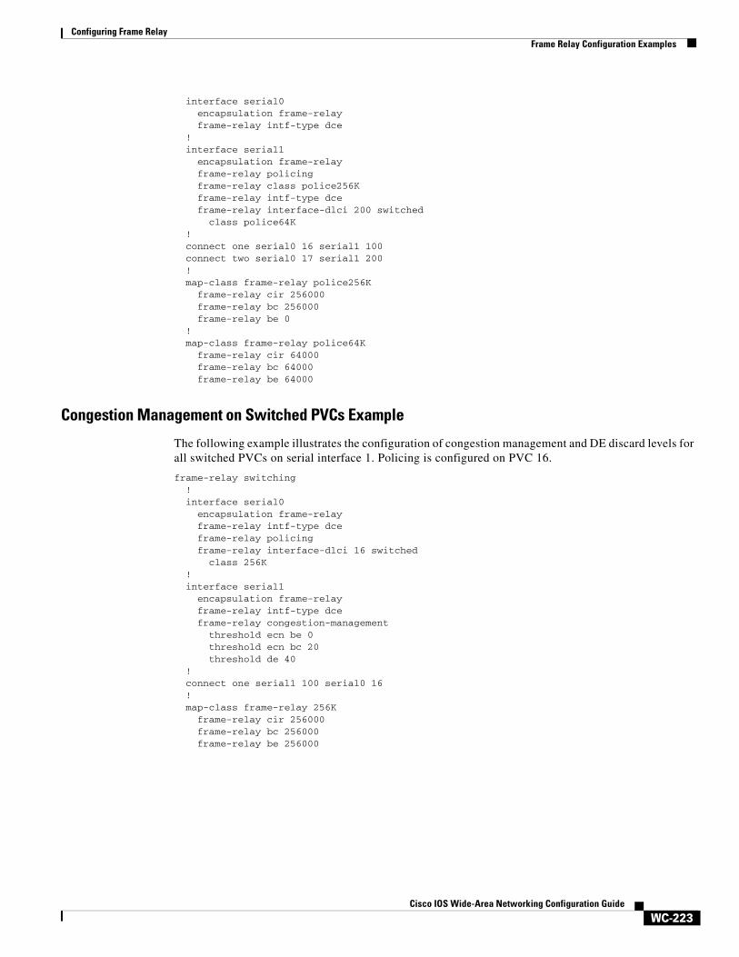
Configuring Frame RelayFrame Relay Configuration Examples
WC-223Cisco IOS Wide-Area Networking Configuration Guide
interface serial0 encapsulation frame-relay frame-relay intf-type dce ! interface serial1 encapsulation frame-relay frame-relay policing frame-relay class police256K frame-relay intf-type dce frame-relay interface-dlci 200 switched class police64K ! connect one serial0 16 serial1 100 connect two serial0 17 serial1 200 ! map-class frame-relay police256K
frame-relay cir 256000 frame-relay bc 256000
frame-relay be 0 ! map-class frame-relay police64K frame-relay cir 64000 frame-relay bc 64000 frame-relay be 64000
Congestion Management on Switched PVCs Example
The following example illustrates the configuration of congestion management and DE discard levels for all switched PVCs on serial interface 1. Policing is configured on PVC 16.
frame-relay switching ! interface serial0 encapsulation frame-relay frame-relay intf-type dce frame-relay policing frame-relay interface-dlci 16 switched class 256K ! interface serial1 encapsulation frame-relay frame-relay intf-type dce frame-relay congestion-management threshold ecn be 0 threshold ecn bc 20 threshold de 40 ! connect one serial1 100 serial0 16 ! map-class frame-relay 256K frame-relay cir 256000 frame-relay bc 256000 frame-relay be 256000
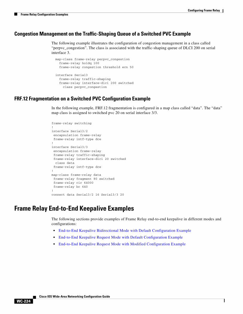
Configuring Frame RelayFrame Relay Configuration Examples
WC-224Cisco IOS Wide-Area Networking Configuration Guide
Congestion Management on the Traffic-Shaping Queue of a Switched PVC Example
The following example illustrates the configuration of congestion management in a class called “perpvc_congestion”. The class is associated with the traffic-shaping queue of DLCI 200 on serial interface 3.
map-class frame-relay perpvc_congestionframe-relay holdq 100frame-relay congestion threshold ecn 50
interface Serial3frame-relay traffic-shapingframe-relay interface-dlci 200 switched
class perpvc_congestion
FRF.12 Fragmentation on a Switched PVC Configuration Example
In the following example, FRF.12 fragmentation is configured in a map class called “data”. The “data” map class is assigned to switched pvc 20 on serial interface 3/3.
frame-relay switching!interface Serial3/2 encapsulation frame-relay frame-relay intf-type dce!interface Serial3/3 encapsulation frame-relay frame-relay traffic-shaping frame-relay interface-dlci 20 switched class data frame-relay intf-type dce!map-class frame-relay data frame-relay fragment 80 switched frame-relay cir 64000 frame-relay bc 640!connect data Serial3/2 16 Serial3/3 20
Frame Relay End-to-End Keepalive ExamplesThe following sections provide examples of Frame Relay end-to-end keepalive in different modes and configurations:
• End-to-End Keepalive Bidirectional Mode with Default Configuration Example
• End-to-End Keepalive Request Mode with Default Configuration Example
• End-to-End Keepalive Request Mode with Modified Configuration Example
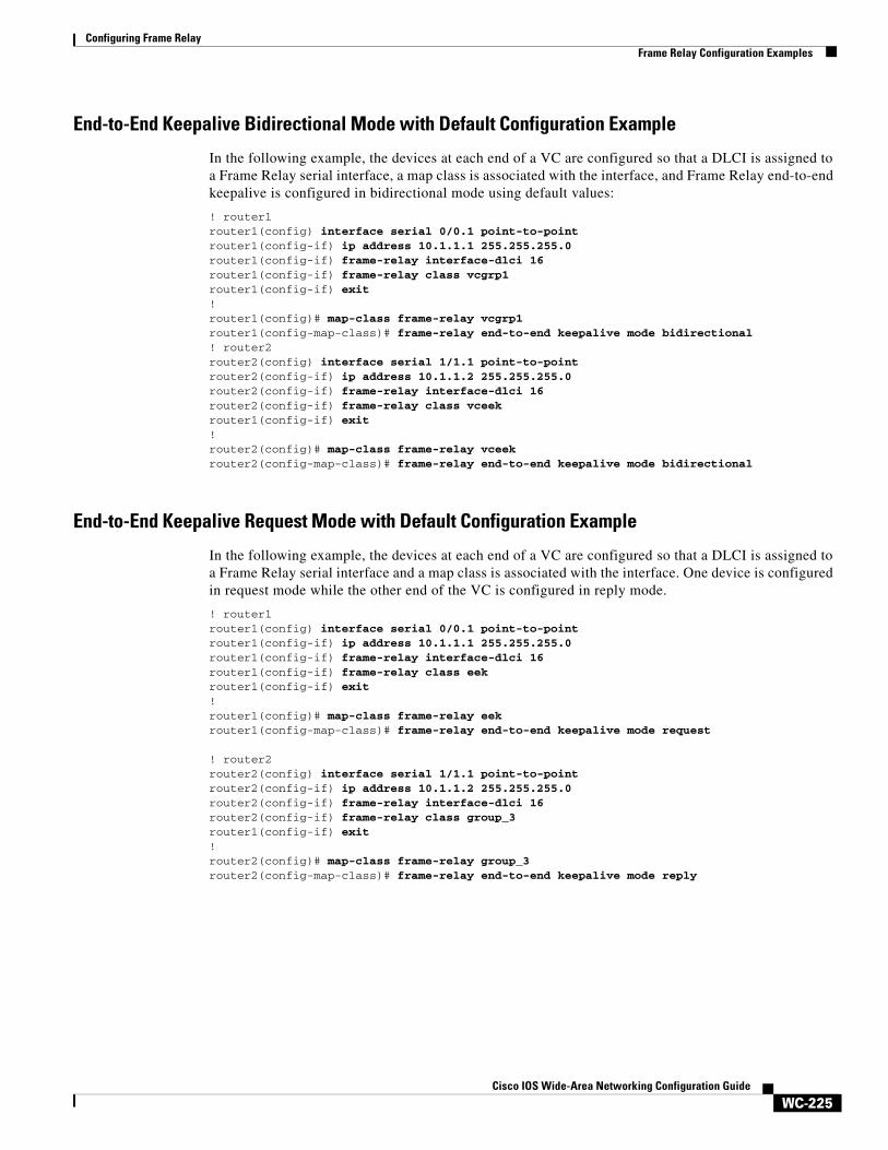
Configuring Frame RelayFrame Relay Configuration Examples
WC-225Cisco IOS Wide-Area Networking Configuration Guide
End-to-End Keepalive Bidirectional Mode with Default Configuration Example
In the following example, the devices at each end of a VC are configured so that a DLCI is assigned to a Frame Relay serial interface, a map class is associated with the interface, and Frame Relay end-to-end keepalive is configured in bidirectional mode using default values:
! router1router1(config) interface serial 0/0.1 point-to-pointrouter1(config-if) ip address 10.1.1.1 255.255.255.0router1(config-if) frame-relay interface-dlci 16router1(config-if) frame-relay class vcgrp1router1(config-if) exit!router1(config)# map-class frame-relay vcgrp1router1(config-map-class)# frame-relay end-to-end keepalive mode bidirectional! router2router2(config) interface serial 1/1.1 point-to-pointrouter2(config-if) ip address 10.1.1.2 255.255.255.0router2(config-if) frame-relay interface-dlci 16router2(config-if) frame-relay class vceekrouter1(config-if) exit!router2(config)# map-class frame-relay vceekrouter2(config-map-class)# frame-relay end-to-end keepalive mode bidirectional
End-to-End Keepalive Request Mode with Default Configuration Example
In the following example, the devices at each end of a VC are configured so that a DLCI is assigned to a Frame Relay serial interface and a map class is associated with the interface. One device is configured in request mode while the other end of the VC is configured in reply mode.
! router1router1(config) interface serial 0/0.1 point-to-pointrouter1(config-if) ip address 10.1.1.1 255.255.255.0router1(config-if) frame-relay interface-dlci 16router1(config-if) frame-relay class eekrouter1(config-if) exit!router1(config)# map-class frame-relay eekrouter1(config-map-class)# frame-relay end-to-end keepalive mode request
! router2router2(config) interface serial 1/1.1 point-to-pointrouter2(config-if) ip address 10.1.1.2 255.255.255.0router2(config-if) frame-relay interface-dlci 16router2(config-if) frame-relay class group_3router1(config-if) exit!router2(config)# map-class frame-relay group_3router2(config-map-class)# frame-relay end-to-end keepalive mode reply
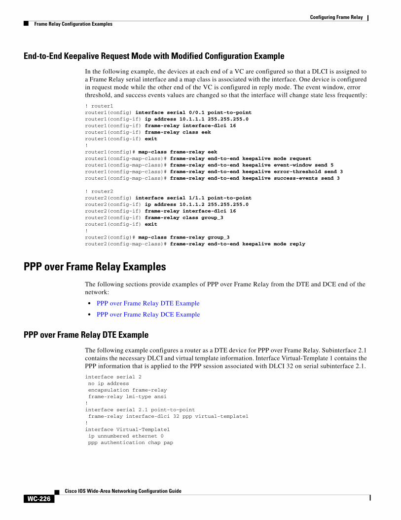
Configuring Frame RelayFrame Relay Configuration Examples
WC-226Cisco IOS Wide-Area Networking Configuration Guide
End-to-End Keepalive Request Mode with Modified Configuration Example
In the following example, the devices at each end of a VC are configured so that a DLCI is assigned to a Frame Relay serial interface and a map class is associated with the interface. One device is configured in request mode while the other end of the VC is configured in reply mode. The event window, error threshold, and success events values are changed so that the interface will change state less frequently:
! router1router1(config) interface serial 0/0.1 point-to-pointrouter1(config-if) ip address 10.1.1.1 255.255.255.0router1(config-if) frame-relay interface-dlci 16router1(config-if) frame-relay class eekrouter1(config-if) exit!router1(config)# map-class frame-relay eekrouter1(config-map-class)# frame-relay end-to-end keepalive mode requestrouter1(config-map-class)# frame-relay end-to-end keepalive event-window send 5router1(config-map-class)# frame-relay end-to-end keepalive error-threshold send 3router1(config-map-class)# frame-relay end-to-end keepalive success-events send 3
! router2router2(config) interface serial 1/1.1 point-to-pointrouter2(config-if) ip address 10.1.1.2 255.255.255.0router2(config-if) frame-relay interface-dlci 16router2(config-if) frame-relay class group_3router1(config-if) exit!router2(config)# map-class frame-relay group_3router2(config-map-class)# frame-relay end-to-end keepalive mode reply
PPP over Frame Relay ExamplesThe following sections provide examples of PPP over Frame Relay from the DTE and DCE end of the network:
• PPP over Frame Relay DTE Example
• PPP over Frame Relay DCE Example
PPP over Frame Relay DTE Example
The following example configures a router as a DTE device for PPP over Frame Relay. Subinterface 2.1 contains the necessary DLCI and virtual template information. Interface Virtual-Template 1 contains the PPP information that is applied to the PPP session associated with DLCI 32 on serial subinterface 2.1.
interface serial 2no ip addressencapsulation frame-relayframe-relay lmi-type ansi
!interface serial 2.1 point-to-pointframe-relay interface-dlci 32 ppp virtual-template1
!interface Virtual-Template1ip unnumbered ethernet 0ppp authentication chap pap
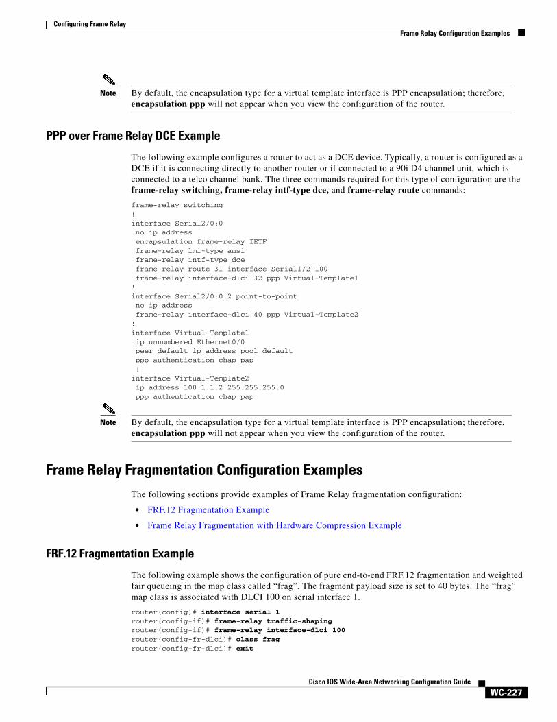
Configuring Frame RelayFrame Relay Configuration Examples
WC-227Cisco IOS Wide-Area Networking Configuration Guide
Note By default, the encapsulation type for a virtual template interface is PPP encapsulation; therefore, encapsulation ppp will not appear when you view the configuration of the router.
PPP over Frame Relay DCE Example
The following example configures a router to act as a DCE device. Typically, a router is configured as a DCE if it is connecting directly to another router or if connected to a 90i D4 channel unit, which is connected to a telco channel bank. The three commands required for this type of configuration are the frame-relay switching, frame-relay intf-type dce, and frame-relay route commands:
frame-relay switching!interface Serial2/0:0 no ip address encapsulation frame-relay IETF frame-relay lmi-type ansi frame-relay intf-type dce frame-relay route 31 interface Serial1/2 100frame-relay interface-dlci 32 ppp Virtual-Template1
!interface Serial2/0:0.2 point-to-point no ip addressframe-relay interface-dlci 40 ppp Virtual-Template2
!interface Virtual-Template1 ip unnumbered Ethernet0/0 peer default ip address pool defaultppp authentication chap pap!
interface Virtual-Template2 ip address 100.1.1.2 255.255.255.0ppp authentication chap pap
Note By default, the encapsulation type for a virtual template interface is PPP encapsulation; therefore, encapsulation ppp will not appear when you view the configuration of the router.
Frame Relay Fragmentation Configuration ExamplesThe following sections provide examples of Frame Relay fragmentation configuration:
• FRF.12 Fragmentation Example
• Frame Relay Fragmentation with Hardware Compression Example
FRF.12 Fragmentation Example
The following example shows the configuration of pure end-to-end FRF.12 fragmentation and weighted fair queueing in the map class called “frag”. The fragment payload size is set to 40 bytes. The “frag” map class is associated with DLCI 100 on serial interface 1.
router(config)# interface serial 1router(config-if)# frame-relay traffic-shapingrouter(config-if)# frame-relay interface-dlci 100router(config-fr-dlci)# class fragrouter(config-fr-dlci)# exit
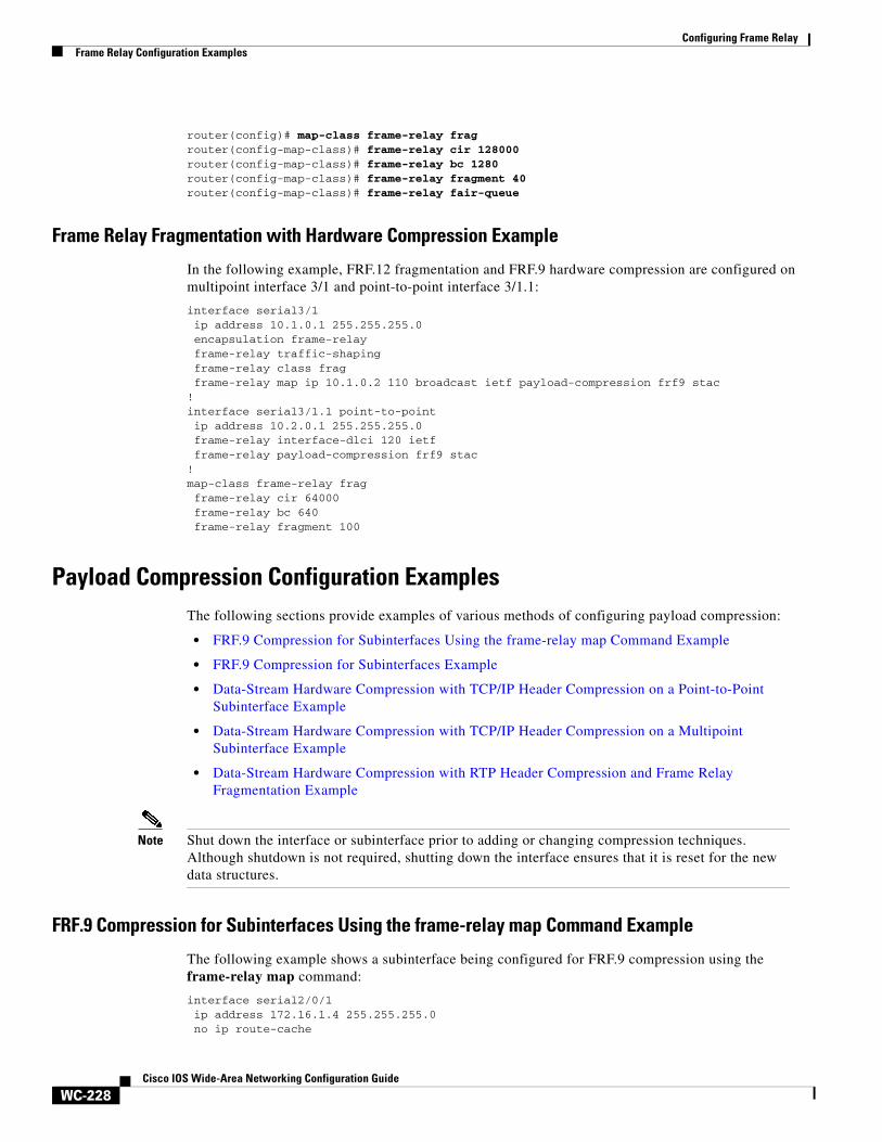
Configuring Frame RelayFrame Relay Configuration Examples
WC-228Cisco IOS Wide-Area Networking Configuration Guide
router(config)# map-class frame-relay fragrouter(config-map-class)# frame-relay cir 128000router(config-map-class)# frame-relay bc 1280router(config-map-class)# frame-relay fragment 40router(config-map-class)# frame-relay fair-queue
Frame Relay Fragmentation with Hardware Compression Example
In the following example, FRF.12 fragmentation and FRF.9 hardware compression are configured on multipoint interface 3/1 and point-to-point interface 3/1.1:
interface serial3/1 ip address 10.1.0.1 255.255.255.0 encapsulation frame-relay frame-relay traffic-shaping frame-relay class frag frame-relay map ip 10.1.0.2 110 broadcast ietf payload-compression frf9 stac!interface serial3/1.1 point-to-point ip address 10.2.0.1 255.255.255.0 frame-relay interface-dlci 120 ietf frame-relay payload-compression frf9 stac!map-class frame-relay frag frame-relay cir 64000 frame-relay bc 640 frame-relay fragment 100
Payload Compression Configuration ExamplesThe following sections provide examples of various methods of configuring payload compression:
• FRF.9 Compression for Subinterfaces Using the frame-relay map Command Example
• FRF.9 Compression for Subinterfaces Example
• Data-Stream Hardware Compression with TCP/IP Header Compression on a Point-to-Point Subinterface Example
• Data-Stream Hardware Compression with TCP/IP Header Compression on a Multipoint Subinterface Example
• Data-Stream Hardware Compression with RTP Header Compression and Frame Relay Fragmentation Example
Note Shut down the interface or subinterface prior to adding or changing compression techniques. Although shutdown is not required, shutting down the interface ensures that it is reset for the new data structures.
FRF.9 Compression for Subinterfaces Using the frame-relay map Command Example
The following example shows a subinterface being configured for FRF.9 compression using the frame-relay map command:
interface serial2/0/1 ip address 172.16.1.4 255.255.255.0 no ip route-cache
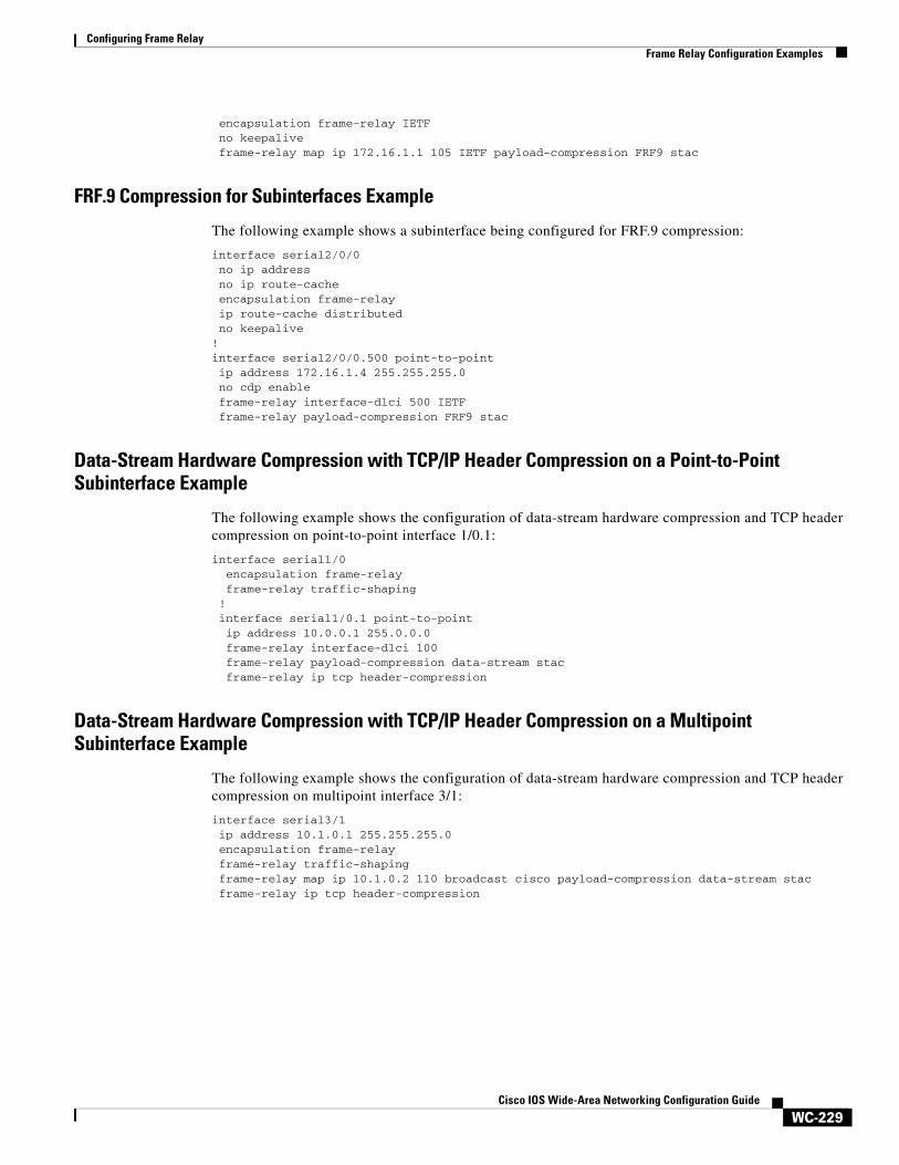
Configuring Frame RelayFrame Relay Configuration Examples
WC-229Cisco IOS Wide-Area Networking Configuration Guide
encapsulation frame-relay IETF no keepalive frame-relay map ip 172.16.1.1 105 IETF payload-compression FRF9 stac
FRF.9 Compression for Subinterfaces Example
The following example shows a subinterface being configured for FRF.9 compression:
interface serial2/0/0 no ip address no ip route-cache encapsulation frame-relay ip route-cache distributed no keepalive!interface serial2/0/0.500 point-to-point ip address 172.16.1.4 255.255.255.0 no cdp enable frame-relay interface-dlci 500 IETF frame-relay payload-compression FRF9 stac
Data-Stream Hardware Compression with TCP/IP Header Compression on a Point-to-Point Subinterface Example
The following example shows the configuration of data-stream hardware compression and TCP header compression on point-to-point interface 1/0.1:
interface serial1/0 encapsulation frame-relay frame-relay traffic-shaping ! interface serial1/0.1 point-to-point ip address 10.0.0.1 255.0.0.0 frame-relay interface-dlci 100
frame-relay payload-compression data-stream stac frame-relay ip tcp header-compression
Data-Stream Hardware Compression with TCP/IP Header Compression on a Multipoint Subinterface Example
The following example shows the configuration of data-stream hardware compression and TCP header compression on multipoint interface 3/1:
interface serial3/1 ip address 10.1.0.1 255.255.255.0 encapsulation frame-relay frame-relay traffic-shapingframe-relay map ip 10.1.0.2 110 broadcast cisco payload-compression data-stream stacframe-relay ip tcp header-compression
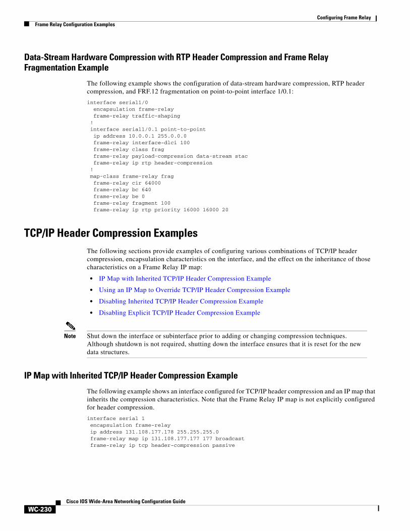
Configuring Frame RelayFrame Relay Configuration Examples
WC-230Cisco IOS Wide-Area Networking Configuration Guide
Data-Stream Hardware Compression with RTP Header Compression and Frame Relay Fragmentation Example
The following example shows the configuration of data-stream hardware compression, RTP header compression, and FRF.12 fragmentation on point-to-point interface 1/0.1:
interface serial1/0 encapsulation frame-relay frame-relay traffic-shaping ! interface serial1/0.1 point-to-point ip address 10.0.0.1 255.0.0.0 frame-relay interface-dlci 100 frame-relay class frag frame-relay payload-compression data-stream stac frame-relay ip rtp header-compression ! map-class frame-relay frag frame-relay cir 64000 frame-relay bc 640 frame-relay be 0 frame-relay fragment 100
frame-relay ip rtp priority 16000 16000 20
TCP/IP Header Compression Examples The following sections provide examples of configuring various combinations of TCP/IP header compression, encapsulation characteristics on the interface, and the effect on the inheritance of those characteristics on a Frame Relay IP map:
• IP Map with Inherited TCP/IP Header Compression Example
• Using an IP Map to Override TCP/IP Header Compression Example
• Disabling Inherited TCP/IP Header Compression Example
• Disabling Explicit TCP/IP Header Compression Example
Note Shut down the interface or subinterface prior to adding or changing compression techniques. Although shutdown is not required, shutting down the interface ensures that it is reset for the new data structures.
IP Map with Inherited TCP/IP Header Compression Example
The following example shows an interface configured for TCP/IP header compression and an IP map that inherits the compression characteristics. Note that the Frame Relay IP map is not explicitly configured for header compression.
interface serial 1encapsulation frame-relayip address 131.108.177.178 255.255.255.0frame-relay map ip 131.108.177.177 177 broadcastframe-relay ip tcp header-compression passive
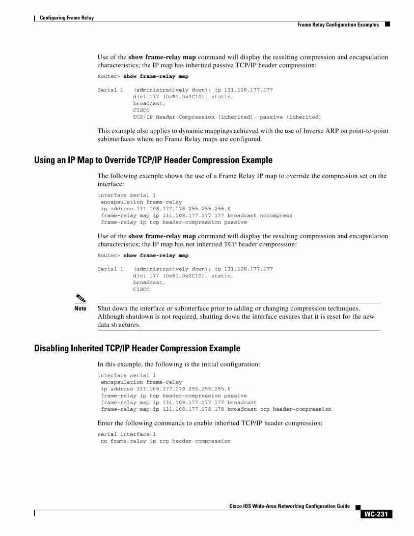
Configuring Frame RelayFrame Relay Configuration Examples
WC-231Cisco IOS Wide-Area Networking Configuration Guide
Use of the show frame-relay map command will display the resulting compression and encapsulation characteristics; the IP map has inherited passive TCP/IP header compression:
Router> show frame-relay map
Serial 1 (administratively down): ip 131.108.177.177 dlci 177 (0xB1,0x2C10), static, broadcast, CISCO TCP/IP Header Compression (inherited), passive (inherited)
This example also applies to dynamic mappings achieved with the use of Inverse ARP on point-to-point subinterfaces where no Frame Relay maps are configured.
Using an IP Map to Override TCP/IP Header Compression Example
The following example shows the use of a Frame Relay IP map to override the compression set on the interface:
interface serial 1encapsulation frame-relayip address 131.108.177.178 255.255.255.0frame-relay map ip 131.108.177.177 177 broadcast nocompressframe-relay ip tcp header-compression passive
Use of the show frame-relay map command will display the resulting compression and encapsulation characteristics; the IP map has not inherited TCP header compression:
Router> show frame-relay map
Serial 1 (administratively down): ip 131.108.177.177 dlci 177 (0xB1,0x2C10), static, broadcast, CISCO
Note Shut down the interface or subinterface prior to adding or changing compression techniques. Although shutdown is not required, shutting down the interface ensures that it is reset for the new data structures.
Disabling Inherited TCP/IP Header Compression Example
In this example, the following is the initial configuration:
interface serial 1encapsulation frame-relayip address 131.108.177.179 255.255.255.0frame-relay ip tcp header-compression passiveframe-relay map ip 131.108.177.177 177 broadcastframe-relay map ip 131.108.177.178 178 broadcast tcp header-compression
Enter the following commands to enable inherited TCP/IP header compression:
serial interface 1no frame-relay ip tcp header-compression
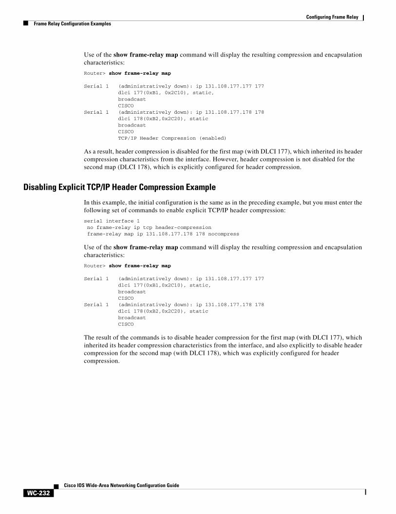
Configuring Frame RelayFrame Relay Configuration Examples
WC-232Cisco IOS Wide-Area Networking Configuration Guide
Use of the show frame-relay map command will display the resulting compression and encapsulation characteristics:
Router> show frame-relay map
Serial 1 (administratively down): ip 131.108.177.177 177 dlci 177(0xB1, 0x2C10), static, broadcast CISCOSerial 1 (administratively down): ip 131.108.177.178 178 dlci 178(0xB2,0x2C20), static broadcast CISCO TCP/IP Header Compression (enabled)
As a result, header compression is disabled for the first map (with DLCI 177), which inherited its header compression characteristics from the interface. However, header compression is not disabled for the second map (DLCI 178), which is explicitly configured for header compression.
Disabling Explicit TCP/IP Header Compression Example
In this example, the initial configuration is the same as in the preceding example, but you must enter the following set of commands to enable explicit TCP/IP header compression:
serial interface 1no frame-relay ip tcp header-compressionframe-relay map ip 131.108.177.178 178 nocompress
Use of the show frame-relay map command will display the resulting compression and encapsulation characteristics:
Router> show frame-relay map
Serial 1 (administratively down): ip 131.108.177.177 177 dlci 177(0xB1,0x2C10), static, broadcast CISCOSerial 1 (administratively down): ip 131.108.177.178 178 dlci 178(0xB2,0x2C20), static broadcast CISCO
The result of the commands is to disable header compression for the first map (with DLCI 177), which inherited its header compression characteristics from the interface, and also explicitly to disable header compression for the second map (with DLCI 178), which was explicitly configured for header compression.


![Configuring TCP Header CompressionRouter(config-if)#encapsulationframe-relay Step 4 Step 5 ipaddressip-addressmask[secondary] SetsaprimaryorsecondaryIPaddressforaninterface. Example:](https://img.pdfslide.us/doc/110x75/60ef2fd2d03e5d732e226634/configuring-tcp-header-compression-routerconfig-ifencapsulationframe-relay-step.jpg)