Embed Size (px)
Citation preview
Cisco CatalyOL-12615-01
C H A P T E R 29
Configuring EtherChannels and Layer 2 Trunk FailoverThis chapter describes how to configure EtherChannels on Layer 2 ports on the switch. EtherChannel provides fault-tolerant high-speed links between switches, routers, and servers. You can use it to increase the bandwidth between the wiring closets and the data center, and you can deploy it anywhere in the network where bottlenecks are likely to occur. EtherChannel provides automatic recovery for the loss of a link by redistributing the load across the remaining links. If a link fails, EtherChannel redirects traffic from the failed link to the remaining links in the channel without intervention.
Note For complete syntax and usage information for the commands used in this chapter, see the command reference for this release.
This chapter consists of these sections:
• Understanding EtherChannels, page 29-1
• Configuring EtherChannels, page 29-8
• Displaying EtherChannel, PAgP, and LACP Status, page 29-17
• Understanding Layer 2 Trunk Failover, page 29-17
Understanding EtherChannelsThese sections describe how EtherChannels work:
• EtherChannel Overview, page 29-2
• Port-Channel Interfaces, page 29-3
• Port Aggregation Protocol, page 29-4
• Link Aggregation Control Protocol, page 29-5
• EtherChannel On Mode, page 29-6
• Load Balancing and Forwarding Methods, page 29-6
29-1st Blade Switch 3030 Software Configuration Guide
Chapter 29 Configuring EtherChannels and Layer 2 Trunk FailoverUnderstanding EtherChannels
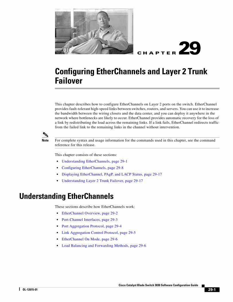
EtherChannel OverviewAn EtherChannel consists of individual Gigabit Ethernet links bundled into a single logical link as shown in Figure 29-1.
Figure 29-1 Typical EtherChannel Configuration
In Figure 29-1, the EtherChannel provides full-duplex bandwidth up to 8 Gb/s (Gigabit EtherChannel) between your switch and another switch or host.
Each EtherChannel can consist of up to eight compatibly configured Ethernet ports. All ports in each EtherChannel must be configured as Layer 2 ports. The number of EtherChannels is limited to 48. For more information, see the “EtherChannel Configuration Guidelines” section on page 29-9.
You can configure an EtherChannel in one of these modes: Port Aggregation Protocol (PAgP), Link Aggregation Control Protocol (LACP), or On. Configure both ends of the EtherChannel in the same mode:
• When you configure one end of an EtherChannel in either PAgP or LACP mode, the system negotiates with the other end of the channel to determine which ports should become active. In previous releases, the incompatible ports were suspended. Beginning with Cisco IOS Release 12.2(35)SE, instead of a suspended state, the local port is put into an independent state and continues to carry data traffic as would any other single link. The port configuration does not change, but the port does not participate in the EtherChannel.
• When you configure an EtherChannel in the on mode, no negotiations take place. The switch forces all compatible ports to become active in the EtherChannel. The other end of the channel (on the other switch) must also be configured in the on mode; otherwise, packet loss can occur.
If a link within an EtherChannel fails, traffic previously carried over that failed link moves to the remaining links within the EtherChannel. If traps are enabled on the switch, a trap is sent for a failure that identifies the switch, the EtherChannel, and the failed link. Inbound broadcast and multicast packets on one link in an EtherChannel are blocked from returning on any other link of the EtherChannel.
Catalyst 6500series switch
Gigabit EtherChannel
BladeSwitch
BladeServer 1
BladeServer 10 14
8960
29-2Cisco Catalyst Blade Switch 3030 Software Configuration Guide
OL-12615-01
Chapter 29 Configuring EtherChannels and Layer 2 Trunk FailoverUnderstanding EtherChannels
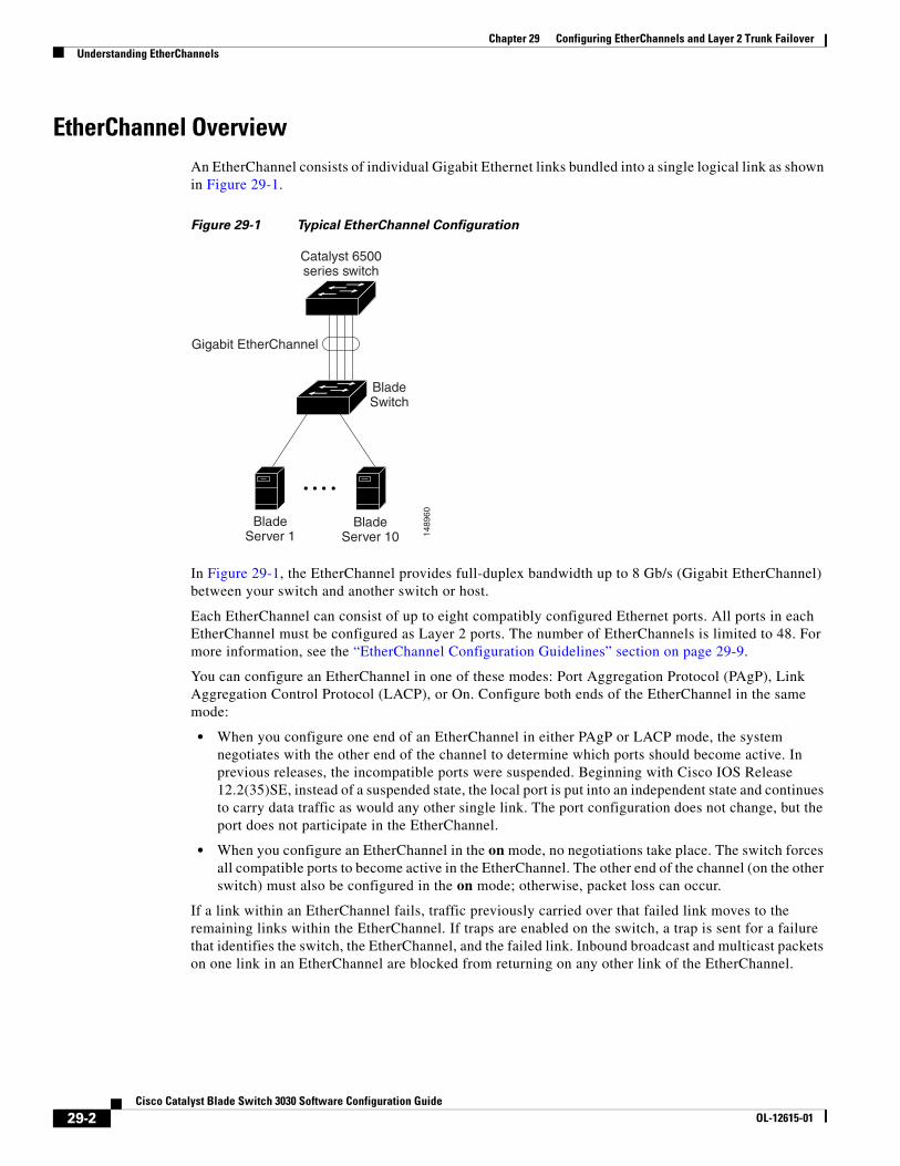
Port-Channel InterfacesWhen you create a Layer 2 EtherChannel, a port-channel logical interface is involved. You can create the EtherChannel in these ways:
• Use the channel-group interface configuration command. This command automatically creates the port-channel logical interface when the channel group gets its first physical port. The channel-group command binds the physical (10/100/1000 ports) and the logical ports together as shown in Figure 29-2.
• Use the interface port-channel port-channel-number global configuration command to manually create the port-channel logical interface. Then use the channel-group channel-group-number interface configuration command to bind the logical interface to a physical port. The channel-group-number can be the same as the port-channel-number, or you can use a new number. If you use a new number, the channel-group command dynamically creates a new port channel.
Each EtherChannel has a port-channel logical interface numbered from 1 to 48. This port-channel interface number corresponds to the one specified with the channel-group interface configuration command.
Figure 29-2 Relationship of Physical Ports, Logical Port Channels, and Channel Groups
After you configure an EtherChannel, configuration changes applied to the port-channel interface apply to all the physical ports assigned to the port-channel interface. Configuration changes applied to the physical port affect only the port where you apply the configuration. To change the parameters of all ports in an EtherChannel, apply configuration commands to the port-channel interface, for example, spanning-tree commands or commands to configure a Layer 2 EtherChannel as a trunk.
1012
38
Channel-groupbinding
Physical ports
Logicalport-channel
29-3Cisco Catalyst Blade Switch 3030 Software Configuration Guide
OL-12615-01
Chapter 29 Configuring EtherChannels and Layer 2 Trunk FailoverUnderstanding EtherChannels
Port Aggregation ProtocolThe Port Aggregation Protocol (PAgP) is a Cisco-proprietary protocol that can be run only on Cisco switches and on those switches licensed by vendors to support PAgP. PAgP facilitates the automatic creation of EtherChannels by exchanging PAgP packets between Ethernet ports.
By using PAgP, the switch learns the identity of partners capable of supporting PAgP and the capabilities of each port. It then dynamically groups similarly configured ports into a single logical link (channel or aggregate port). Similarly configured ports are grouped based on hardware, administrative, and port parameter constraints. For example, PAgP groups the ports with the same speed, duplex mode, native VLAN, VLAN range, and trunking status and type. After grouping the links into an EtherChannel, PAgP adds the group to the spanning tree as a single switch port.
PAgP Modes
Table 29-1 shows the user-configurable EtherChannel PAgP modes for the channel-group interface configuration command.
Switch ports exchange PAgP packets only with partner ports configured in the auto or desirable modes. Ports configured in the on mode do not exchange PAgP packets.
Both the auto and desirable modes enable ports to negotiate with partner ports to form an EtherChannel based on criteria such as port speed and, for Layer 2 EtherChannels, trunking state and VLAN numbers.
Ports can form an EtherChannel when they are in different PAgP modes as long as the modes are compatible. For example:
• A port in the desirable mode can form an EtherChannel with another port that is in the desirable or auto mode.
• A port in the auto mode can form an EtherChannel with another port in the desirable mode.
A port in the auto mode cannot form an EtherChannel with another port that is also in the auto mode because neither port starts PAgP negotiation.
If your switch is connected to a partner that is PAgP-capable, you can configure the switch port for nonsilent operation by using the non-silent keyword. If you do not specify non-silent with the auto or desirable mode, silent mode is assumed.
Use the silent mode when the switch is connected to a device that is not PAgP-capable and seldom, if ever, sends packets. An example of a silent partner is a file server or a packet analyzer that is not generating traffic. In this case, running PAgP on a physical port connected to a silent partner prevents that switch port from ever becoming operational. However, the silent setting allows PAgP to operate, to attach the port to a channel group, and to use the port for transmission.
Table 29-1 EtherChannel PAgP Modes
Mode Description
auto Places a port into a passive negotiating state, in which the port responds to PAgP packets it receives but does not start PAgP packet negotiation. This setting minimizes the transmission of PAgP packets.
desirable Places a port into an active negotiating state, in which the port starts negotiations with other ports by sending PAgP packets.
29-4Cisco Catalyst Blade Switch 3030 Software Configuration Guide
OL-12615-01
Chapter 29 Configuring EtherChannels and Layer 2 Trunk FailoverUnderstanding EtherChannels
PAgP Interaction with Other Features
The Dynamic Trunking Protocol (DTP) and the Cisco Discovery Protocol (CDP) send and receive packets over the physical ports in the EtherChannel. Trunk ports send and receive PAgP protocol data units (PDUs) on the lowest numbered VLAN.
In Layer 2 EtherChannels, the first port in the channel that comes up provides its MAC address to the EtherChannel. If this port is removed from the bundle, one of the remaining ports in the bundle provides its MAC address to the EtherChannel.PAgP sends and receives PAgP PDUs only from ports that are up and have PAgP enabled for the auto or desirable mode.
Link Aggregation Control ProtocolThe LACP is defined in IEEE 802.3ad and enables Cisco switches to manage Ethernet channels between switches that conform to the IEEE 802.3ad protocol. LACP facilitates the automatic creation of EtherChannels by exchanging LACP packets between Ethernet ports.
By using LACP, the switch learns the identity of partners capable of supporting LACP and the capabilities of each port. It then dynamically groups similarly configured ports into a single logical link (channel or aggregate port). Similarly configured ports are grouped based on hardware, administrative, and port parameter constraints. For example, LACP groups the ports with the same speed, duplex mode, native VLAN, VLAN range, and trunking status and type. After grouping the links into an EtherChannel, LACP adds the group to the spanning tree as a single switch port.
LACP Modes
Table 29-2 shows the user-configurable EtherChannel LACP modes for the channel-group interface configuration command.
Both the active and passive LACP modes enable ports to negotiate with partner ports to an EtherChannel based on criteria such as port speed and, for Layer 2 EtherChannels, trunking state and VLAN numbers.
Ports can form an EtherChannel when they are in different LACP modes as long as the modes are compatible. For example:
• A port in the active mode can form an EtherChannel with another port that is in the active or passive mode.
• A port in the passive mode cannot form an EtherChannel with another port that is also in the passive mode because neither port starts LACP negotiation.
Table 29-2 EtherChannel LACP Modes
Mode Description
active Places a port into an active negotiating state in which the port starts negotiations with other ports by sending LACP packets.
passive Places a port into a passive negotiating state in which the port responds to LACP packets that it receives, but does not start LACP packet negotiation. This setting minimizes the transmission of LACP packets.
29-5Cisco Catalyst Blade Switch 3030 Software Configuration Guide
OL-12615-01
Chapter 29 Configuring EtherChannels and Layer 2 Trunk FailoverUnderstanding EtherChannels
LACP Interaction with Other Features
The DTP and the CDP send and receive packets over the physical ports in the EtherChannel. Trunk ports send and receive LACP PDUs on the lowest numbered VLAN.
In Layer 2 EtherChannels, the first port in the channel that comes up provides its MAC address to the EtherChannel. If this port is removed from the bundle, one of the remaining ports in the bundle provides its MAC address to the EtherChannel.
LACP sends and receives LACP PDUs only from ports that are up and have LACP enabled for the active or passive mode.
EtherChannel On ModeEtherChannel on mode can be used to manually configure an EtherChannel. The on mode forces a port to join an EtherChannel without negotiations. The on mode can be useful if the remote device does not support PAgP or LACP. In the on mode, a usable EtherChannel exists only when the switches at both ends of the link are configured in the on mode.
Ports that are configured in the on mode in the same channel group must have compatible port characteristics, such as speed and duplex. Ports that are not compatible are suspended, even though they are configured in the on mode.
Caution You should use care when using the on mode. This is a manual configuration, and ports on both ends of the EtherChannel must have the same configuration. If the group is misconfigured, packet loss or spanning-tree loops can occur.
Load Balancing and Forwarding MethodsEtherChannel balances the traffic load across the links in a channel by reducing part of the binary pattern formed from the addresses in the frame to a numerical value that selects one of the links in the channel. EtherChannel load balancing can use MAC addresses or IP addresses, source or destination addresses, or both source and destination addresses. The selected mode applies to all EtherChannels configured on the switch. You configure the load balancing and forwarding method by using the port-channel load-balance global configuration command.
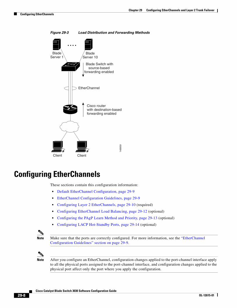
With source-MAC address forwarding, when packets are forwarded to an EtherChannel, they are distributed across the ports in the channel based on the source-MAC address of the incoming packet. Therefore, to provide load balancing, packets from different hosts use different ports in the channel, but packets from the same host use the same port in the channel.
With destination-MAC address forwarding, when packets are forwarded to an EtherChannel, they are distributed across the ports in the channel based on the destination host’s MAC address of the incoming packet. Therefore, packets to the same destination are forwarded over the same port, and packets to a different destination are sent on a different port in the channel.
With source-and-destination MAC address forwarding, when packets are forwarded to an EtherChannel, they are distributed across the ports in the channel based on both the source and destination MAC addresses. This forwarding method, a combination source-MAC and destination-MAC address forwarding methods of load distribution, can be used if it is not clear whether source-MAC or destination-MAC address forwarding is better suited on a particular switch. With source-and-destination MAC-address forwarding, packets sent from host A to host B, host A to host C, and host C to host B could all use different ports in the channel.
29-6Cisco Catalyst Blade Switch 3030 Software Configuration Guide
OL-12615-01
Chapter 29 Configuring EtherChannels and Layer 2 Trunk FailoverUnderstanding EtherChannels
With source-IP address-based forwarding, when packets are forwarded to an EtherChannel, they are distributed across the ports in the EtherChannel based on the source-IP address of the incoming packet. Therefore, to provide load-balancing, packets from different IP addresses use different ports in the channel, but packets from the same IP address use the same port in the channel.
With destination-IP address-based forwarding, when packets are forwarded to an EtherChannel, they are distributed across the ports in the EtherChannel based on the destination-IP address of the incoming packet. Therefore, to provide load-balancing, packets from the same IP source address sent to different IP destination addresses could be sent on different ports in the channel. But packets sent from different source IP addresses to the same destination IP address are always sent on the same port in the channel.
With source-and-destination IP address-based forwarding, packets are sent to an EtherChannel and distributed across the EtherChannel ports, based on both the source and destination IP addresses of the incoming packet. This forwarding method, a combination of source-IP and destination-IP address-based forwarding, can be used if it is not clear whether source-IP or destination-IP address-based forwarding is better suited on a particular switch. In this method, packets sent from the IP address A to IP address B, from IP address A to IP address C, and from IP address C to IP address B could all use different ports in the channel.
Different load-balancing methods have different advantages, and the choice of a particular load-balancing method should be based on the position of the switch in the network and the kind of traffic that needs to be load-distributed. In Figure 29-3, an EtherChannel from a blade switch that is aggregating data from ten blade servers communicates with a router. Because the router is a single-MAC-address device, source-based forwarding on the switch EtherChannel ensures that the switch uses all available bandwidth to the router. The router is configured for destination-based forwarding because the large number of workstations ensures that the traffic is evenly distributed from the router EtherChannel.
Use the option that provides the greatest variety in your configuration. For example, if the traffic on a channel is only going to a single MAC address, using the destination-MAC address always chooses the same link in the channel. Using source addresses or IP addresses might result in better load balancing.
29-7Cisco Catalyst Blade Switch 3030 Software Configuration Guide
OL-12615-01
Chapter 29 Configuring EtherChannels and Layer 2 Trunk FailoverConfiguring EtherChannels
Figure 29-3 Load Distribution and Forwarding Methods
Configuring EtherChannelsThese sections contain this configuration information:
• Default EtherChannel Configuration, page 29-9
• EtherChannel Configuration Guidelines, page 29-9
• Configuring Layer 2 EtherChannels, page 29-10 (required)
• Configuring EtherChannel Load Balancing, page 29-12 (optional)
• Configuring the PAgP Learn Method and Priority, page 29-13 (optional)
• Configuring LACP Hot-Standby Ports, page 29-14 (optional)
Note Make sure that the ports are correctly configured. For more information, see the “EtherChannel Configuration Guidelines” section on page 29-9.
Note After you configure an EtherChannel, configuration changes applied to the port-channel interface apply to all the physical ports assigned to the port-channel interface, and configuration changes applied to the physical port affect only the port where you apply the configuration.
1489
59
Cisco routerwith destination-basedforwarding enabled
EtherChannel
Blade Switch withsource-based
forwarding enabled
BladeServer 1
BladeServer 10
Client Client
29-8Cisco Catalyst Blade Switch 3030 Software Configuration Guide
OL-12615-01
Chapter 29 Configuring EtherChannels and Layer 2 Trunk FailoverConfiguring EtherChannels
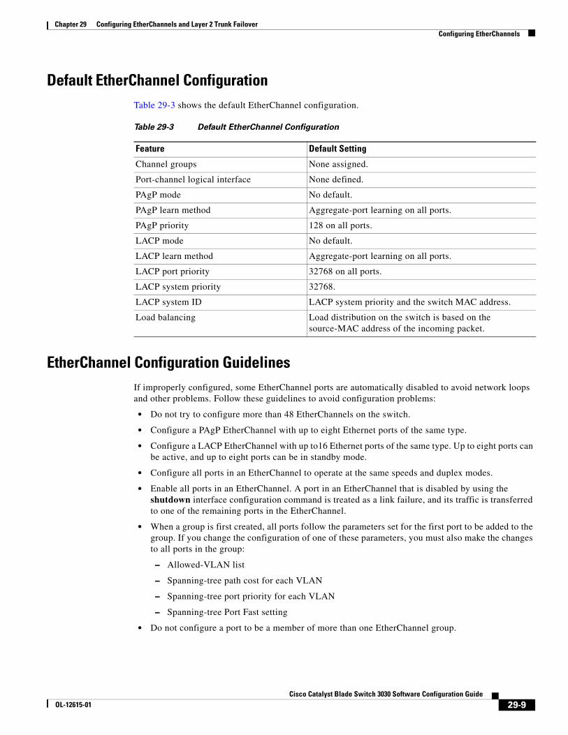
Default EtherChannel ConfigurationTable 29-3 shows the default EtherChannel configuration.
EtherChannel Configuration GuidelinesIf improperly configured, some EtherChannel ports are automatically disabled to avoid network loops and other problems. Follow these guidelines to avoid configuration problems:
• Do not try to configure more than 48 EtherChannels on the switch.
• Configure a PAgP EtherChannel with up to eight Ethernet ports of the same type.
• Configure a LACP EtherChannel with up to16 Ethernet ports of the same type. Up to eight ports can be active, and up to eight ports can be in standby mode.
• Configure all ports in an EtherChannel to operate at the same speeds and duplex modes.
• Enable all ports in an EtherChannel. A port in an EtherChannel that is disabled by using the shutdown interface configuration command is treated as a link failure, and its traffic is transferred to one of the remaining ports in the EtherChannel.
• When a group is first created, all ports follow the parameters set for the first port to be added to the group. If you change the configuration of one of these parameters, you must also make the changes to all ports in the group:
– Allowed-VLAN list
– Spanning-tree path cost for each VLAN
– Spanning-tree port priority for each VLAN
– Spanning-tree Port Fast setting
• Do not configure a port to be a member of more than one EtherChannel group.
Table 29-3 Default EtherChannel Configuration
Feature Default Setting
Channel groups None assigned.
Port-channel logical interface None defined.
PAgP mode No default.
PAgP learn method Aggregate-port learning on all ports.
PAgP priority 128 on all ports.
LACP mode No default.
LACP learn method Aggregate-port learning on all ports.
LACP port priority 32768 on all ports.
LACP system priority 32768.
LACP system ID LACP system priority and the switch MAC address.
Load balancing Load distribution on the switch is based on the source-MAC address of the incoming packet.
29-9Cisco Catalyst Blade Switch 3030 Software Configuration Guide
OL-12615-01
Chapter 29 Configuring EtherChannels and Layer 2 Trunk FailoverConfiguring EtherChannels
• Do not configure an EtherChannel in both the PAgP and LACP modes. EtherChannel groups running PAgP and LACP can coexist on the same switch. Individual EtherChannel groups can run either PAgP or LACP, but they cannot interoperate.
• Do not configure a Switched Port Analyzer (SPAN) destination port as part of an EtherChannel.
• Do not configure a secure port as part of an EtherChannel or the reverse.
• Do not configure a port that is an active or a not-yet-active member of an EtherChannel as an IEEE 802.1x port. If you try to enable IEEE 802.1x on an EtherChannel port, an error message appears, and IEEE 802.1x is not enabled.
• If EtherChannels are configured on switch interfaces, remove the EtherChannel configuration from the interfaces before globally enabling IEEE 802.1x on a switch by using the dot1x system-auth-control global configuration command.
• For Layer 2 EtherChannels:
– Assign all ports in the EtherChannel to the same VLAN, or configure them as trunks. Ports with different native VLANs cannot form an EtherChannel.
– If you configure an EtherChannel from trunk ports, verify that the trunking mode (ISL or IEEE 802.1Q) is the same on all the trunks. Inconsistent trunk modes on EtherChannel ports can have unexpected results.
– An EtherChannel supports the same allowed range of VLANs on all the ports in a trunking Layer 2 EtherChannel. If the allowed range of VLANs is not the same, the ports do not form an EtherChannel even when PAgP is set to the auto or desirable mode.
– Ports with different spanning-tree path costs can form an EtherChannel if they are otherwise compatibly configured. Setting different spanning-tree path costs does not, by itself, make ports incompatible for the formation of an EtherChannel.
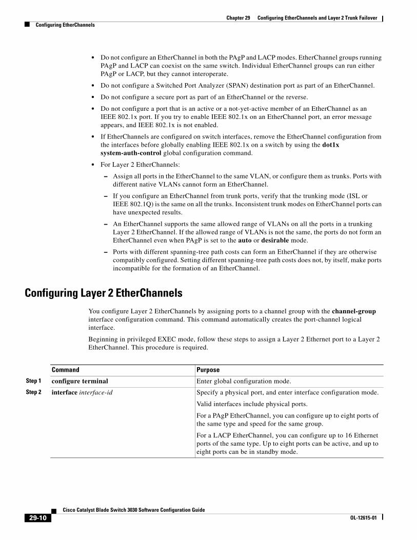
Configuring Layer 2 EtherChannels You configure Layer 2 EtherChannels by assigning ports to a channel group with the channel-group interface configuration command. This command automatically creates the port-channel logical interface.
Beginning in privileged EXEC mode, follow these steps to assign a Layer 2 Ethernet port to a Layer 2 EtherChannel. This procedure is required.
Command Purpose
Step 1 configure terminal Enter global configuration mode.
Step 2 interface interface-id Specify a physical port, and enter interface configuration mode.
Valid interfaces include physical ports.
For a PAgP EtherChannel, you can configure up to eight ports of the same type and speed for the same group.
For a LACP EtherChannel, you can configure up to 16 Ethernet ports of the same type. Up to eight ports can be active, and up to eight ports can be in standby mode.
29-10Cisco Catalyst Blade Switch 3030 Software Configuration Guide
OL-12615-01
Chapter 29 Configuring EtherChannels and Layer 2 Trunk FailoverConfiguring EtherChannels
To remove a port from the EtherChannel group, use the no channel-group interface configuration command.
Step 3 switchport mode {access | trunk}
switchport access vlan vlan-id
Assign all ports as static-access ports in the same VLAN, or configure them as trunks.
If you configure the port as a static-access port, assign it to only one VLAN. The range is 1 to 4094.
Step 4 channel-group channel-group-number mode {auto [non-silent] | desirable [non-silent] | on} | {active | passive}
Assign the port to a channel group, and specify the PAgP or the LACP mode.
For channel-group-number, the range is 1 to 48.
For mode, select one of these keywords:
• auto—Enables PAgP only if a PAgP device is detected. It places the port into a passive negotiating state, in which the port responds to PAgP packets it receives but does not start PAgP packet negotiation.
• desirable—Unconditionally enables PAgP. It places the port into an active negotiating state, in which the port starts negotiations with other ports by sending PAgP packets.
• on—Forces the port to channel without PAgP or LACP. In the on mode, an EtherChannel exists only when a port group in the on mode is connected to another port group in the on mode.
• non-silent—(Optional) If your switch is connected to a partner that is PAgP-capable, configure the switch port for nonsilent operation when the port is in the auto or desirable mode. If you do not specify non-silent, silent is assumed. The silent setting is for connections to file servers or packet analyzers. This setting allows PAgP to operate, to attach the port to a channel group, and to use the port for transmission.
• active—Enables LACP only if a LACP device is detected. It places the port into an active negotiating state in which the port starts negotiations with other ports by sending LACP packets.
• passive—Enables LACP on the port and places it into a passive negotiating state in which the port responds to LACP packets that it receives, but does not start LACP packet negotiation.
For information on compatible modes for the switch and its partner, see the “PAgP Modes” section on page 29-4 and the “LACP Modes” section on page 29-5.
Step 5 end Return to privileged EXEC mode.
Step 6 show running-config Verify your entries.
Step 7 copy running-config startup-config (Optional) Save your entries in the configuration file.
Command Purpose
29-11Cisco Catalyst Blade Switch 3030 Software Configuration Guide
OL-12615-01
Chapter 29 Configuring EtherChannels and Layer 2 Trunk FailoverConfiguring EtherChannels
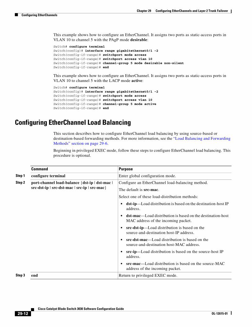
This example shows how to configure an EtherChannel. It assigns two ports as static-access ports in VLAN 10 to channel 5 with the PAgP mode desirable:
Switch# configure terminal Switch(config)# interface range gigabitethernet0/1 -2 Switch(config-if-range)# switchport mode accessSwitch(config-if-range)# switchport access vlan 10Switch(config-if-range)# channel-group 5 mode desirable non-silentSwitch(config-if-range)# end
This example shows how to configure an EtherChannel. It assigns two ports as static-access ports in VLAN 10 to channel 5 with the LACP mode active:
Switch# configure terminal Switch(config)# interface range gigabitethernet0/1 -2 Switch(config-if-range)# switchport mode accessSwitch(config-if-range)# switchport access vlan 10Switch(config-if-range)# channel-group 5 mode activeSwitch(config-if-range)# end
Configuring EtherChannel Load BalancingThis section describes how to configure EtherChannel load balancing by using source-based or destination-based forwarding methods. For more information, see the “Load Balancing and Forwarding Methods” section on page 29-6.
Beginning in privileged EXEC mode, follow these steps to configure EtherChannel load balancing. This procedure is optional.
Command Purpose
Step 1 configure terminal Enter global configuration mode.
Step 2 port-channel load-balance {dst-ip | dst-mac | src-dst-ip | src-dst-mac | src-ip | src-mac}
Configure an EtherChannel load-balancing method.
The default is src-mac.
Select one of these load-distribution methods:
• dst-ip—Load distribution is based on the destination-host IP address.
• dst-mac—Load distribution is based on the destination-host MAC address of the incoming packet.
• src-dst-ip—Load distribution is based on the source-and-destination host-IP address.
• src-dst-mac—Load distribution is based on the source-and-destination host-MAC address.
• src-ip—Load distribution is based on the source-host IP address.
• src-mac—Load distribution is based on the source-MAC address of the incoming packet.
Step 3 end Return to privileged EXEC mode.
29-12Cisco Catalyst Blade Switch 3030 Software Configuration Guide
OL-12615-01
Chapter 29 Configuring EtherChannels and Layer 2 Trunk FailoverConfiguring EtherChannels
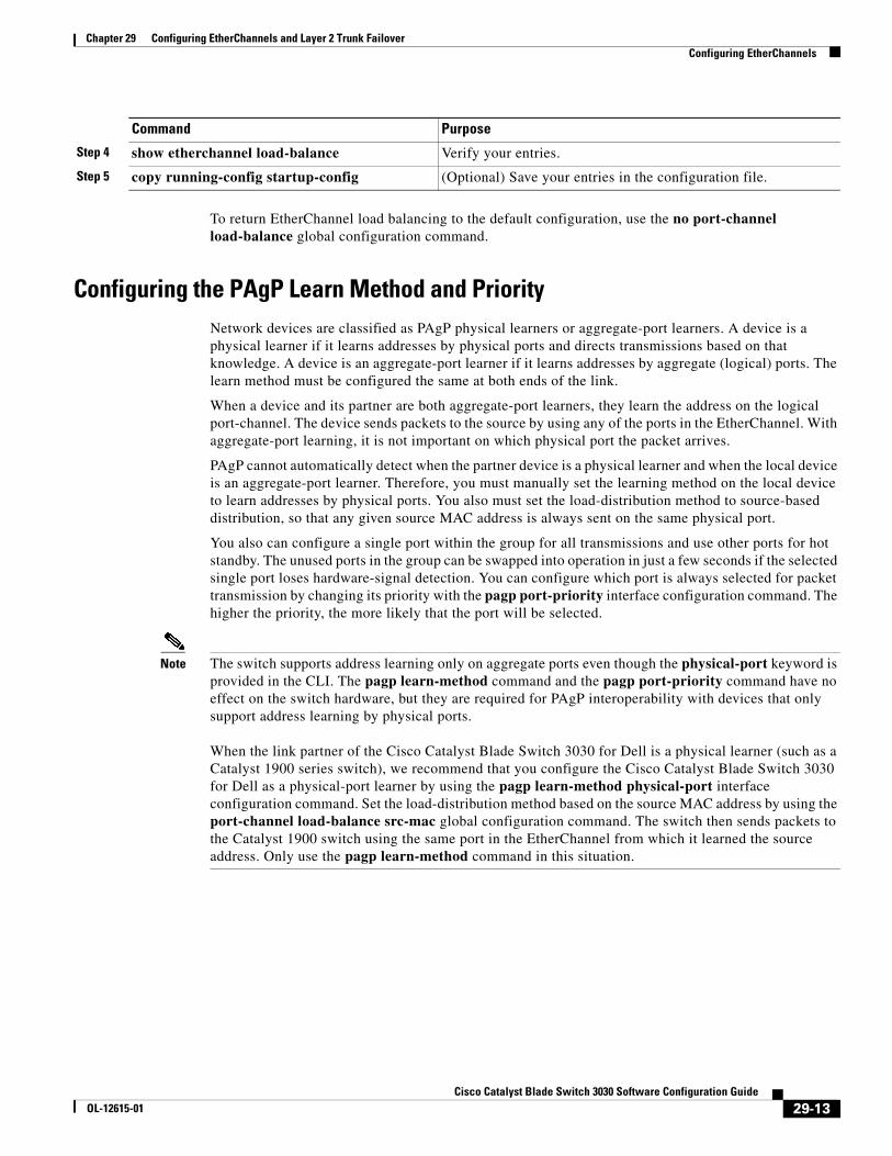
To return EtherChannel load balancing to the default configuration, use the no port-channel load-balance global configuration command.
Configuring the PAgP Learn Method and PriorityNetwork devices are classified as PAgP physical learners or aggregate-port learners. A device is a physical learner if it learns addresses by physical ports and directs transmissions based on that knowledge. A device is an aggregate-port learner if it learns addresses by aggregate (logical) ports. The learn method must be configured the same at both ends of the link.
When a device and its partner are both aggregate-port learners, they learn the address on the logical port-channel. The device sends packets to the source by using any of the ports in the EtherChannel. With aggregate-port learning, it is not important on which physical port the packet arrives.
PAgP cannot automatically detect when the partner device is a physical learner and when the local device is an aggregate-port learner. Therefore, you must manually set the learning method on the local device to learn addresses by physical ports. You also must set the load-distribution method to source-based distribution, so that any given source MAC address is always sent on the same physical port.
You also can configure a single port within the group for all transmissions and use other ports for hot standby. The unused ports in the group can be swapped into operation in just a few seconds if the selected single port loses hardware-signal detection. You can configure which port is always selected for packet transmission by changing its priority with the pagp port-priority interface configuration command. The higher the priority, the more likely that the port will be selected.
Note The switch supports address learning only on aggregate ports even though the physical-port keyword is provided in the CLI. The pagp learn-method command and the pagp port-priority command have no effect on the switch hardware, but they are required for PAgP interoperability with devices that only support address learning by physical ports.
When the link partner of the Cisco Catalyst Blade Switch 3030 for Dell is a physical learner (such as a Catalyst 1900 series switch), we recommend that you configure the Cisco Catalyst Blade Switch 3030 for Dell as a physical-port learner by using the pagp learn-method physical-port interface configuration command. Set the load-distribution method based on the source MAC address by using the port-channel load-balance src-mac global configuration command. The switch then sends packets to the Catalyst 1900 switch using the same port in the EtherChannel from which it learned the source address. Only use the pagp learn-method command in this situation.
Step 4 show etherchannel load-balance Verify your entries.
Step 5 copy running-config startup-config (Optional) Save your entries in the configuration file.
Command Purpose
29-13Cisco Catalyst Blade Switch 3030 Software Configuration Guide
OL-12615-01
Chapter 29 Configuring EtherChannels and Layer 2 Trunk FailoverConfiguring EtherChannels
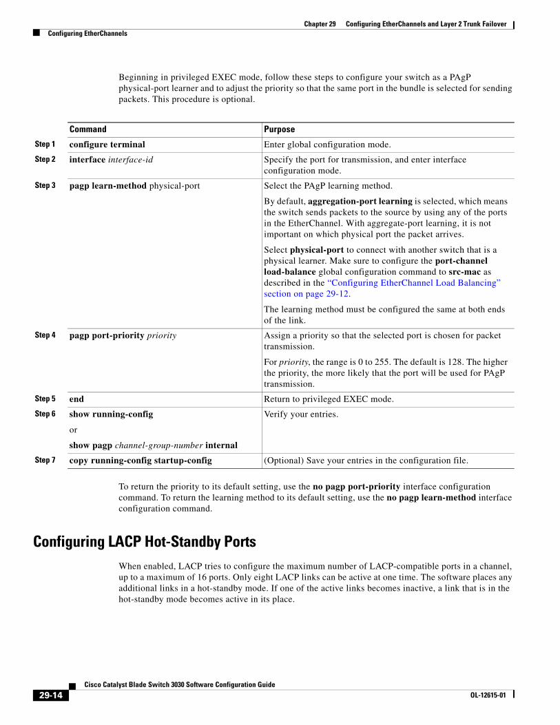
Beginning in privileged EXEC mode, follow these steps to configure your switch as a PAgP physical-port learner and to adjust the priority so that the same port in the bundle is selected for sending packets. This procedure is optional.
To return the priority to its default setting, use the no pagp port-priority interface configuration command. To return the learning method to its default setting, use the no pagp learn-method interface configuration command.
Configuring LACP Hot-Standby PortsWhen enabled, LACP tries to configure the maximum number of LACP-compatible ports in a channel, up to a maximum of 16 ports. Only eight LACP links can be active at one time. The software places any additional links in a hot-standby mode. If one of the active links becomes inactive, a link that is in the hot-standby mode becomes active in its place.
Command Purpose
Step 1 configure terminal Enter global configuration mode.
Step 2 interface interface-id Specify the port for transmission, and enter interface configuration mode.
Step 3 pagp learn-method physical-port Select the PAgP learning method.
By default, aggregation-port learning is selected, which means the switch sends packets to the source by using any of the ports in the EtherChannel. With aggregate-port learning, it is not important on which physical port the packet arrives.
Select physical-port to connect with another switch that is a physical learner. Make sure to configure the port-channel load-balance global configuration command to src-mac as described in the “Configuring EtherChannel Load Balancing” section on page 29-12.
The learning method must be configured the same at both ends of the link.
Step 4 pagp port-priority priority Assign a priority so that the selected port is chosen for packet transmission.
For priority, the range is 0 to 255. The default is 128. The higher the priority, the more likely that the port will be used for PAgP transmission.
Step 5 end Return to privileged EXEC mode.
Step 6 show running-config
or
show pagp channel-group-number internal
Verify your entries.
Step 7 copy running-config startup-config (Optional) Save your entries in the configuration file.
29-14Cisco Catalyst Blade Switch 3030 Software Configuration Guide
OL-12615-01
Chapter 29 Configuring EtherChannels and Layer 2 Trunk FailoverConfiguring EtherChannels
If you configure more than eight links for an EtherChannel group, the software automatically decides which of the hot-standby ports to make active based on the LACP priority. To every link between systems that operate LACP, the software assigns a unique priority made up of these elements (in priority order):
• LACP system priority
• System ID (the switch MAC address)
• LACP port priority
• Port number
In priority comparisons, numerically lower values have higher priority. The priority decides which ports should be put in standby mode when there is a hardware limitation that prevents all compatible ports from aggregating.
Determining which ports are active and which are hot standby is a two-step procedure. First the system with a numerically lower system priority and system-id is placed in charge of the decision. Next, that system decides which ports are active and which are hot standby, based on its values for port priority and port number. The port-priority and port-number values for the other system are not used.
You can change the default values of the LACP system priority and the LACP port priority to affect how the software selects active and standby links. For more information, see the “Configuring the LACP System Priority” section on page 29-15 and the “Configuring the LACP Port Priority” section on page 29-16.
Configuring the LACP System Priority
You can configure the system priority for all the EtherChannels that are enabled for LACP by using the lacp system-priority global configuration command. You cannot configure a system priority for each LACP-configured channel. By changing this value from the default, you can affect how the software selects active and standby links.
You can use the show etherchannel summary privileged EXEC command to see which ports are in the hot-standby mode (denoted with an H port-state flag).
Beginning in privileged EXEC mode, follow these steps to configure the LACP system priority. This procedure is optional.
To return the LACP system priority to the default value, use the no lacp system-priority global configuration command.
Command Purpose
Step 1 configure terminal Enter global configuration mode.
Step 2 lacp system-priority priority Configure the LACP system priority.
For priority, the range is 1 to 65535. The default is 32768.
The lower the value, the higher the system priority.
Step 3 end Return to privileged EXEC mode.
Step 4 show running-config
or
show lacp sys-id
Verify your entries.
Step 5 copy running-config startup-config (Optional) Save your entries in the configuration file.
29-15Cisco Catalyst Blade Switch 3030 Software Configuration Guide
OL-12615-01
Chapter 29 Configuring EtherChannels and Layer 2 Trunk FailoverConfiguring EtherChannels
Configuring the LACP Port Priority
By default, all ports use the same port priority. If the local system has a lower value for the system priority and the system ID than the remote system, you can affect which of the hot-standby links become active first by changing the port priority of LACP EtherChannel ports to a lower value than the default. The hot-standby ports that have lower port numbers become active in the channel first. You can use the show etherchannel summary privileged EXEC command to see which ports are in the hot-standby mode (denoted with an H port-state flag).
Note If LACP is not able to aggregate all the ports that are compatible (for example, the remote system might have more restrictive hardware limitations), all the ports that cannot be actively included in the EtherChannel are put in the hot-standby state and are used only if one of the channeled ports fails.
Beginning in privileged EXEC mode, follow these steps to configure the LACP port priority. This procedure is optional.
To return the LACP port priority to the default value, use the no lacp port-priority interface configuration command.
Command Purpose
Step 1 configure terminal Enter global configuration mode.
Step 2 interface interface-id Specify the port to be configured, and enter interface configuration mode.
Step 3 lacp port-priority priority Configure the LACP port priority.
For priority, the range is 1 to 65535. The default is 32768. The lower the value, the more likely that the port will be used for LACP transmission.
Step 4 end Return to privileged EXEC mode.
Step 5 show running-config
or
show lacp [channel-group-number] internal
Verify your entries.
Step 6 copy running-config startup-config (Optional) Save your entries in the configuration file.
29-16Cisco Catalyst Blade Switch 3030 Software Configuration Guide
OL-12615-01
Chapter 29 Configuring EtherChannels and Layer 2 Trunk FailoverDisplaying EtherChannel, PAgP, and LACP Status
Displaying EtherChannel, PAgP, and LACP StatusTo display EtherChannel, PAgP, and LACP status information, use the privileged EXEC commands described in Table 29-4:
You can clear PAgP channel-group information and traffic counters by using the clear pagp {channel-group-number counters | counters} privileged EXEC command.
You can clear LACP channel-group information and traffic counters by using the clear lacp {channel-group-number counters | counters} privileged EXEC command.
For detailed information about the fields in the displays, see the command reference for this release.
Understanding Layer 2 Trunk FailoverLayer 2 trunk failover, also known as link-state tracking, is a feature that provides Layer 2 redundancy in the network when used with server NIC adapter teaming. When the server network adapters are configured in a primary or secondary relationship known as teaming, if the link is lost on the primary interface, connectivity is transparently switched to the secondary interface.
When you enable Layer 2 trunk failover on the switch, the link state of the internal downstream ports are bound to the link state of one or more of the external upstream ports. An internal downstream port is an interface that is connected to the server. An external upstream port is an interface that is connected to the external network. When you associate a set of downstream ports to a set of upstream ports, if all of the upstream ports become unavailable, trunk failover automatically puts all of the associated downstream ports in an error-disabled state. This causes the server primary interface to failover to the secondary interface.
When Layer 2 trunk failover is not enabled, if the upstream interfaces lose connectivity, (the external switch or router goes down, the cables are disconnected, or link is lost), the link state of the downstream interfaces remain unchanged. The server is not aware that external connectivity has been lost and does not failover to the secondary interface.
An interface can be an aggregation of ports (an EtherChannel), or a single physical port in access or trunk mode. Each downstream interface can be associated with one or more upstream interfaces. Upstream interfaces can be bundled together, and each downstream interface can be associated with a single group consisting of multiple upstream interfaces. These groups are referred to as link-state groups.
Table 29-4 Commands for Displaying EtherChannel, PAgP, and LACP Status
Command Description
show etherchannel [channel-group-number {detail | port | port-channel | protocol | summary}] {detail | load-balance | port | port-channel | protocol | summary}
Displays EtherChannel information in a brief, detailed, and one-line summary form. Also displays the load-balance or frame-distribution scheme, port, port-channel, and protocol information.
show pagp [channel-group-number] {counters | internal | neighbor}
Displays PAgP information such as traffic information, the internal PAgP configuration, and neighbor information.
show lacp [channel-group-number] {counters | internal | neighbor}
Displays LACP information such as traffic information, the internal LACP configuration, and neighbor information.
29-17Cisco Catalyst Blade Switch 3030 Software Configuration Guide
OL-12615-01
Chapter 29 Configuring EtherChannels and Layer 2 Trunk FailoverUnderstanding Layer 2 Trunk Failover
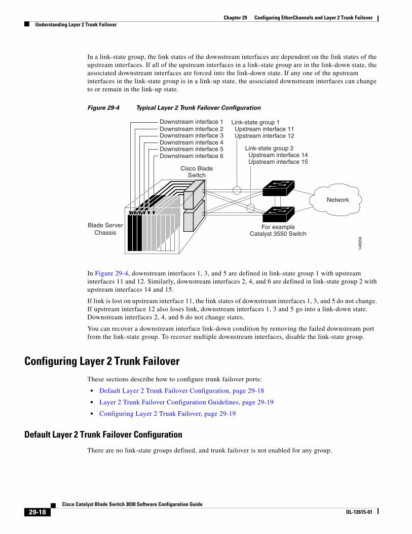
In a link-state group, the link states of the downstream interfaces are dependent on the link states of the upstream interfaces. If all of the upstream interfaces in a link-state group are in the link-down state, the associated downstream interfaces are forced into the link-down state. If any one of the upstream interfaces in the link-state group is in a link-up state, the associated downstream interfaces can change to or remain in the link-up state.
Figure 29-4 Typical Layer 2 Trunk Failover Configuration
In Figure 29-4, downstream interfaces 1, 3, and 5 are defined in link-state group 1 with upstream interfaces 11 and 12. Similarly, downstream interfaces 2, 4, and 6 are defined in link-state group 2 with upstream interfaces 14 and 15.
If link is lost on upstream interface 11, the link states of downstream interfaces 1, 3, and 5 do not change. If upstream interface 12 also loses link, downstream interfaces 1, 3 and 5 go into a link-down state. Downstream interfaces 2, 4, and 6 do not change states.
You can recover a downstream interface link-down condition by removing the failed downstream port from the link-state group. To recover multiple downstream interfaces, disable the link-state group.
Configuring Layer 2 Trunk FailoverThese sections describe how to configure trunk failover ports:
• Default Layer 2 Trunk Failover Configuration, page 29-18
• Layer 2 Trunk Failover Configuration Guidelines, page 29-19
• Configuring Layer 2 Trunk Failover, page 29-19
Default Layer 2 Trunk Failover Configuration
There are no link-state groups defined, and trunk failover is not enabled for any group.
Blade ServerChassis
For exampleCatalyst 3550 Switch
1489
56
Downstream interface 1 Link-state group 1 Upstream interface 11 Upstream interface 12
Cisco BladeSwitch
Downstream interface 2Downstream interface 3Downstream interface 4Downstream interface 5Downstream interface 6
Network
Link-state group 2 Upstream interface 14 Upstream interface 15
29-18Cisco Catalyst Blade Switch 3030 Software Configuration Guide
OL-12615-01
Chapter 29 Configuring EtherChannels and Layer 2 Trunk FailoverUnderstanding Layer 2 Trunk Failover
Layer 2 Trunk Failover Configuration Guidelines
Follow these guidelines to avoid configuration problems:
• Do not configure a cross-connect interface (gi0/ or gi0/) as a member of a link-stategroup.
• Do not configure an EtherChannel as a downstream interface.
• Only interfaces gi0/1 through gi0/10 can be configured as downstream ports in a specific link-state group.
• Only interfaces gi0/11 through gi0/16 can be configured as upstream ports in a specific link-state group.
• An interface that is defined as an upstream interface cannot also be defined as a downstream interface in the same or a different link-state group. The reverse is also true.
• An interface cannot be a member of more than one link-state group.
• You can configure only two link-state groups per switch.
Configuring Layer 2 Trunk Failover
Beginning in privileged EXEC mode, follow these steps to configure a link-state group and to assign an interface to a group:
This example shows how to create a link-state group and configure the interfaces:
Switch# configure terminal Switch(config)# link state track 1Switch(config)# interface range gigabitethernet0/13 - 14Switch(config-if)# link state group 1 upstreamSwitch(config-if)# interface gigabitethernet0/1 Switch(config-if)# link state group 1 downstreamSwitch(config-if)# interface gigabitethernet0/3 Switch(config-if)# link state group 1 downstreamSwitch(config-if)# interface gigabitethernet0/5 Switch(config-if)# link state group 1 downstreamSwitch(config-if)# end
Command Purpose
Step 1 configure terminal Enter global configuration mode.
Step 2 link state track number Create a link-state group, and enable link-state tracking. The group number can be 1 or 2; the default is 1.
Step 3 interface interface-id Specify a physical interface or range of interfaces to configure, and enter interface configuration mode.
Valid interfaces include physical ports in access or trunk mode (IEEE 802.1q) or multiple physical ports bundled into an EtherChannel interface (static or LACP), also in trunk mode.
Step 4 link state group [number] {upstream | downstream}
Specify a link-state group, and configure the interface as either an upstream or downstream interface in the group.
Step 5 end Return to privileged EXEC mode.
Step 6 show running-config Verify your entries.
Step 7 copy running-config startup-config (Optional) Save your entries in the configuration file.
29-19Cisco Catalyst Blade Switch 3030 Software Configuration Guide
OL-12615-01
Chapter 29 Configuring EtherChannels and Layer 2 Trunk FailoverUnderstanding Layer 2 Trunk Failover
Note If the interfaces are part of an EtherChannel, you must specify the port channel name as part of the link-state group, not the individual port members.
This example shows how to create a link-state group using ports in an EtherChannel:
Switch# configure terminal Switch(config)# link state track 1Switch(config)# interface P01Switch(config-if)# link state group 1 upstreamSwitch(config-if-range)# interface range gigabitethernet0/1, gigabitethernet0/3, gigabitethernet0/5Switch(config-if)# link state group 1 downstreamSwitch(config-if)# end
To disable a link-state group, use the no link state track number global configuration command.
Displaying Layer 2 Trunk Failover Status
Use the show link state group command to display the link-state group information. Enter this command without keywords to display information about all link-state groups. Enter the group number to display information specific to the group. Enter the detail keyword to display detailed information about the group.
This is an example of output from the show link state group 1 command:
Switch> show link state group 1
Link State Group: 1 Status: Enabled, Up
This is an example of output from the show link state group detail command:
Switch> show link state group detailLink State Group: 1 Status: Enabled, UpUpstream Interfaces : Po1(Up)Downstream Interfaces : Gi0/3(Up) Gi0/4(Up)
Link State Group: 2 Status: Disabled, DownUpstream Interfaces :Downstream Interfaces :
(Up):Interface up (Dwn):Interface Down (Dis):Interface disabled
For detailed information about the fields in the display, see the command reference for this release.
29-20Cisco Catalyst Blade Switch 3030 Software Configuration Guide
OL-12615-01


![[MS-CSVP]: Failover Cluster: Setup and Validation … · Failover Cluster: Setup and Validation Protocol ... Failover Cluster: Setup and Validation Protocol (ClusPrep) ... cluster](https://img.pdfslide.us/doc/110x75/5add98057f8b9ae1408d3169/ms-csvp-failover-cluster-setup-and-validation-cluster-setup-and-validation.jpg)