Embed Size (px)
Citation preview
C H A P T E R
Configuring and Monitoring from the Switch Manager 3-1
3
Configuring and Monitoringfrom the Switch ManagerThis chapter explains how to use the switch manager to change the configuration settingsand to monitor the switch. This chapter assumes that you have already performed thesepreliminary tasks that are described in this guide or in theQuick Start Guide: Catalyst 1900Series Ethernet Switches:
• “Connecting to the Console Port” section on page 2-16
• “Assigning IP Information and a Password to the Switch” section on page 2-19
• “Accessing the Switch Manager” section on page 2-34
Note The switch manager online help also provides the procedures for changing theconfiguration settings and detailed descriptions of the fields.
Note This chapter describes only standard-edition options. For information about theenterprise edition software features such as VLANs, see theCatalyst 1900 Series andCatalyst 2820 Series Enterprise Edition Software Configuration Guide.
Navigating the Switch Manager
Catalyst 1900 Series Installation and Configuration Guide3-2
Navigating the Switch ManagerAt the top of each switch manager page is a menu bar. Figure 3-1 describes the functionsof the pages accessible from this bar.
Note On Netscape Communicator, when the cursor is above a topic on the menu bar, apop-up briefly describes the options on that particular page.
Figure 3-1 Switch Manager Menu Bar
1028
9
Basic switchdescription;
switch image;switch password
Address tableinformation;display Port
SecurityTable page
Spanning-treesettings Port
monitoringsettings
Exception andutilization
statistics reports
CGMP settings;IP multicast addresses;multicast router ports
Port settingsand statistics
SNMP communitystrings; trap and write
manager settings
NeighboringCisco devices;
Cisco Discovery Protocolsettings
Consoleport settings;
firmware upgrade
IP information;switch performance settings;
traffic control
Configuring and Monitoring from the Switch Manager 3-3
Making Changes from the Switch Manager
Making Changes from the Switch ManagerYou can change the switch settings by entering information into fields, adding andremoving list items, or selecting and deselecting check boxes. ClickApply to save yourchanges. ClickCancel to discardall yourunsaved changes and to return the previoussettings to the page.
Note After you clickApply, you cannot revert to the previous settings.
Note Wait approximately 1 minute for the changes to be saved to permanent storagebefore turning off the switch, or the changes might not be saved.
• When you enter information in fields and select or deselect check boxes, the changesare saved and take effect immediately after you clickApply.
• When you add items to or remove them from lists, the changes take effect immediately.It is not necessary to clickApply.
• If you are using Microsoft Internet Explorer 5.0 to make configuration changes to theswitch, be aware that this browser does not reflect the latest configuration changes.Make sure you click the browserRefresh button for every configuration change.
Assigning or Changing Basic Switch Information
Catalyst 1900 Series Installation and Configuration Guide3-4
Assigning or Changing Basic Switch InformationYou can assign or change basic descriptions about the switch. You can also assign anencrypted (secret) privileged-level password to the switch management interfaces andmonitor network activity through the live switch image.
From the switch manager, you can open a Telnet session on the management console andcontact Cisco Systems resources.
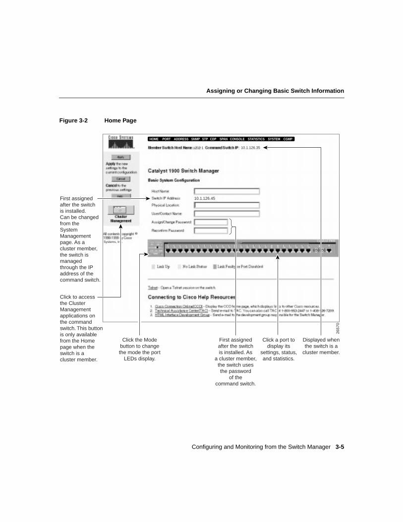
To display the Home Page (Figure 3-2), clickHOME on the menu bar.
Configuring and Monitoring from the Switch Manager 3-5
Assigning or Changing Basic Switch Information
Figure 3-2 Home Page
First assignedafter the switchis installed.Can be changedfrom theSystemManagementpage. As acluster member,the switch ismanagedthrough the IPaddress of thecommand switch.
Click to accessthe ClusterManagementapplications onthe commandswitch. This buttonis only availablefrom the Homepage when theswitch is acluster member.
2657
0Displayed whenthe switch is a
cluster member.
Click the Modebutton to changethe mode the port
LEDs display.
Click a port todisplay its
settings, status,and statistics.
HOME PORT ADDRESS CGMPSNMP STP CDP SPAN CONSOLE STATISTICS SYSTEM
10.1.126.35
10.1.126.45
Systems, Inc.
First assignedafter the switchis installed. As
a cluster member,the switch usesthe password
of thecommand switch.
1
Assigning or Changing Basic Switch Information
Catalyst 1900 Series Installation and Configuration Guide3-6
Assigning or Changing the Switch Host Name and DescriptionYou can assign or change the following information about the switch:
• Name of the switch (maximum of 255 characters)
• Physical location of the switch (maximum of 255 characters)
• Name of the person responsible for managing the switch (maximum of 255 characters)
Switch Host Name
Caution Do not use “-NN” (whereNN is a number) in the name you define for the switch.When the switch joins a cluster, the command switch overwrites any name containing“-NN.”
The name you assign to the switch is kept even when the switch joins or leaves a cluster. Ifthe switch does not have a name before it joins a cluster, the command switch assigns it aname that consists of the command-switch name and a number that reflects when the switchwas added to the cluster. For example, a command switch can name a Catalyst 1900 switcheng-cluster-5, whereeng-cluster is the command-switch name and5 means that it is thefifth switch to join the cluster. When the switch name is viewed from the ClusterManagement applications, the name is truncated to 32 characters. If the switch leaves thecluster, the switch keeps the name given by the command switch.
When the switch is a cluster member, the Member Switch Host Name field also displaysthe switch name at the top of each switch manager page. Therefore, the names in the HostName and Member Switch Host Name fields are identical.
Configuring and Monitoring from the Switch Manager 3-7
Assigning or Changing the Switch Host Name and Description
Switch and Command-Switch IP AddressesThe Switch IP Address field displays the IP address of the switch itself, which is typicallyassigned after the switch is installed. (See the “Assigning IP Information and a Password tothe Switch” section on page 2-19.) If the switch does not have an IP address, the Switch IPAddress field displays 0.0.0.0. When the switch is a cluster member, the Command SwitchIP field displays the command-switch IP address at the top of each switch manager page.
IP information identifies the switch on the network and is required to configure and monitorit as an individual switch. When you assign the switch its own IP address, you can manageit from its management interfaces (switch manager, management console, SNMP, or CLI).The switch retains its own IP address even when it joins or leaves a switch cluster.
If you do not assign an IP address to the switch, you must add the switch to a switch clusterand manage it through the command switch. Whether or not the switch has its own IPaddress, when the switch is a cluster member, it is managed and communicates with othermember switches through the IP address of the command switch. If the switch leaves thecluster and it does not have its own IP address, you then must assign IP information to it tomanage and monitor it as a nonmember switch.
Note We recommend that you assign an IP address to the switch even if the switch is orwill be a cluster member so that if the switch is removed from the cluster, it remainsmanageable as a nonmember switch.
For additional information, see the “Assigning or Changing IP Information” section onpage 3-70. For information about IP information in switch clusters, refer to theCisco IOSDesktop Switch Software Configuration Guide, Catalyst 2900 Series XL and Catalyst 3500Series XL Cisco IOS Release 12.0(5)XP.
Assigning or Changing Basic Switch Information
Catalyst 1900 Series Installation and Configuration Guide3-8
Changing the Switch PasswordA privileged-level password (encrypted or unencrypted) is required to access the switchmanagement interfaces (switch manager, management console through a Telnet session, orCLI).
The password you assign from the Assign/Change Password field on the Home Page is anencrypted (secret) privileged-level password. This password provides higher security andsupersedes any existing unencrypted privileged-level password, including the unencryptedprivileged-level password that is assigned from the [P] Console Password option on theManagement Console Logon Screen. (For information about where you can assignprivileged-level passwords, see the “Privileged-Level Passwords” section on page 3-9.)
Follow these steps to assign an encrypted privileged-level password to the switch or tochange the existing switch password to an encrypted privileged-level password:
Step 1 Enter a new password in the Assign/Change Password field. The password canbe 1 to 25 characters and iscase sensitive. You can use any character found onthe keyboard, including spaces and double-quotation marks. A multistringpassword (such astwo words) is also valid.
Step 2 Reenter the same string in the Reconfirm Password field.
Step 3 Click Apply.
Step 4 Access the switch manager by using the newly assigned password.
Note When the switch is shipped, no password is assigned to it. However, aprivileged-level password is required to access the Catalyst 1900 Switch Manager or to useTelnet access from a remote station. If you do not assign a password, this access will not beavailable until the switch joins a cluster or until you assign the switch a privileged-levelpassword from the management console (see the “Console Settings Menu” section onpage 4-6) through a direct connection to the switch console port.
Configuring and Monitoring from the Switch Manager 3-9
Changing the Switch Password
When your switch is a cluster member, the highest privileged-level password for thecommand switch is the privileged-level password to the switch. The command-switchpassword overwrites any switch-specific passwords. For more information aboutpasswords in switch clusters, see the “Cluster Member Passwords” section on page 3-10.
Note We do not recommend changing the password while the switch is a cluster member.This will cause a password mismatch, and you will have to manually enter the clustermember password to display the switch manager from the command switch.
If you have lost or forgotten the password, see the “Recovering from a Lost or ForgottenPassword” section on page 5-15.
Privileged-Level PasswordsIf you plan to manage the switch outside of a switch cluster, you can assign an unencryptedor encrypted privileged-level password to the switch to restrict access to its managementinterfaces (Table 3-1).
Read and Write community strings operate as passwords to the switch when managing itfrom an SNMP management station. See the “Changing the SNMP Settings” section onpage 3-35.
For information about the user-level passwords, refer to the online-onlyCatalyst 1900Series and Catalyst 2820 Series Command Reference.
Table 3-1 Assigning Privileged-Level Passwords
Privileged-LevelPassword Assigned from...
Unencrypted • [P] Console Password option on the Management Console Logon Screen
• [M] Modify password option on the Console Settings Menu
• CLI
Encrypted • Home Page
• [E] Modify secret password option on the Console Settings Menu
• CLI
Assigning or Changing Basic Switch Information
Catalyst 1900 Series Installation and Configuration Guide3-10
Cluster Member PasswordsWhen the switch joins a cluster, the highest privileged-level password (encrypted orunencrypted) of the command switch supersedes any existing password for the switch.Keep in mind the following considerations:
• When you add the switch to a cluster, inform other users that they must now use thecommand-switch password to access the switch management interfaces.
• If the command switch does not have a password, no password is required whenaccessing the member switch from the command switch.
• When the switch leaves the cluster, it retains the command-switch password. You canassign a different privileged-level (encrypted or unencrypted) password to the switch tomanage and monitor it as a nonmember switch.
Note We do not recommend changing the password while the switch is a cluster member.This will cause a password mismatch, and you will have to manually enter the clustermember password to display the switch manager from the command switch.
For password information about switch clusters, refer to theCisco IOS Desktop SwitchSoftware Configuration Guide, Catalyst 2900 Series XL and Catalyst 3500 Series XL CiscoIOS Release 12.0(5)XP.
Configuring and Monitoring from the Switch Manager 3-11
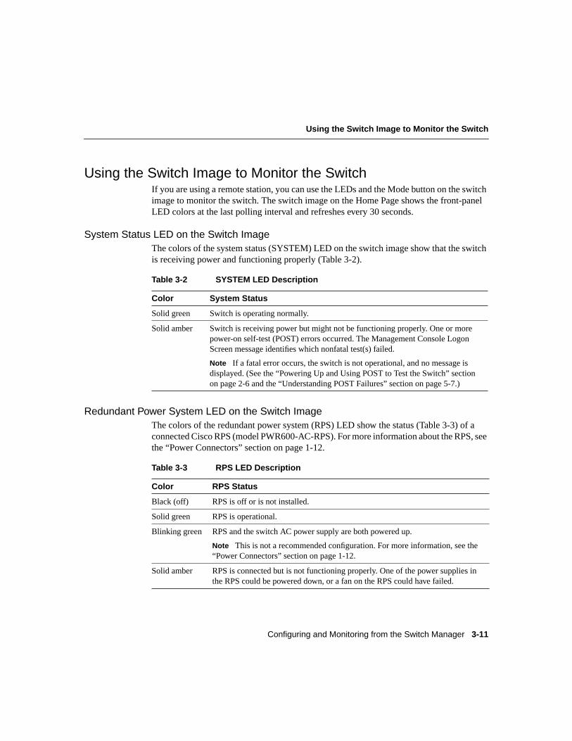
Using the Switch Image to Monitor the Switch
Using the Switch Image to Monitor the SwitchIf you are using a remote station, you can use the LEDs and the Mode button on the switchimage to monitor the switch. The switch image on the Home Page shows the front-panelLED colors at the last polling interval and refreshes every 30 seconds.
System Status LED on the Switch ImageThe colors of the system status (SYSTEM) LED on the switch image show that the switchis receiving power and functioning properly (Table 3-2).
Redundant Power System LED on the Switch ImageThe colors of the redundant power system (RPS) LED show the status (Table 3-3) of aconnected Cisco RPS (model PWR600-AC-RPS). For more information about the RPS, seethe “Power Connectors” section on page 1-12.
Table 3-2 SYSTEM LED Description
Color System Status
Solid green Switch is operating normally.
Solid amber Switch is receiving power but might not be functioning properly. One or morepower-on self-test (POST) errors occurred. The Management Console LogonScreen message identifies which nonfatal test(s) failed.
Note If a fatal error occurs, the switch is not operational, and no message isdisplayed. (See the “Powering Up and Using POST to Test the Switch” sectionon page 2-6 and the “Understanding POST Failures” section on page 5-7.)
Table 3-3 RPS LED Description
Color RPS Status
Black (off) RPS is off or is not installed.
Solid green RPS is operational.
Blinking green RPS and the switch AC power supply are both powered up.
Note This is not a recommended configuration. For more information, see the“Power Connectors” section on page 1-12.
Solid amber RPS is connected but is not functioning properly. One of the power supplies inthe RPS could be powered down, or a fan on the RPS could have failed.
Assigning or Changing Basic Switch Information
Catalyst 1900 Series Installation and Configuration Guide3-12
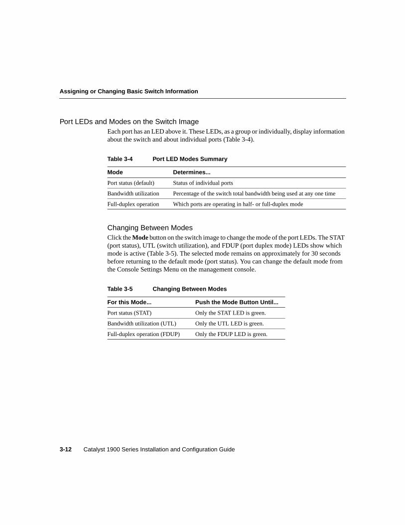
Port LEDs and Modes on the Switch ImageEach port has an LED above it. These LEDs, as a group or individually, display informationabout the switch and about individual ports (Table 3-4).
Changing Between ModesClick theModebutton on the switch image to change the mode of the port LEDs. The STAT(port status), UTL (switch utilization), and FDUP (port duplex mode) LEDs show whichmode is active (Table 3-5). The selected mode remains on approximately for 30 secondsbefore returning to the default mode (port status). You can change the default mode fromthe Console Settings Menu on the management console.
Table 3-4 Port LED Modes Summary
Mode Determines...
Port status (default) Status of individual ports
Bandwidth utilization Percentage of the switch total bandwidth being used at any one time
Full-duplex operation Which ports are operating in half- or full-duplex mode
Table 3-5 Changing Between Modes
For this Mode... Push the Mode Button Until...
Port status (STAT) Only the STAT LED is green.
Bandwidth utilization (UTL) Only the UTL LED is green.
Full-duplex operation (FDUP) Only the FDUP LED is green.
Configuring and Monitoring from the Switch Manager 3-13
Using the Switch Image to Monitor the Switch
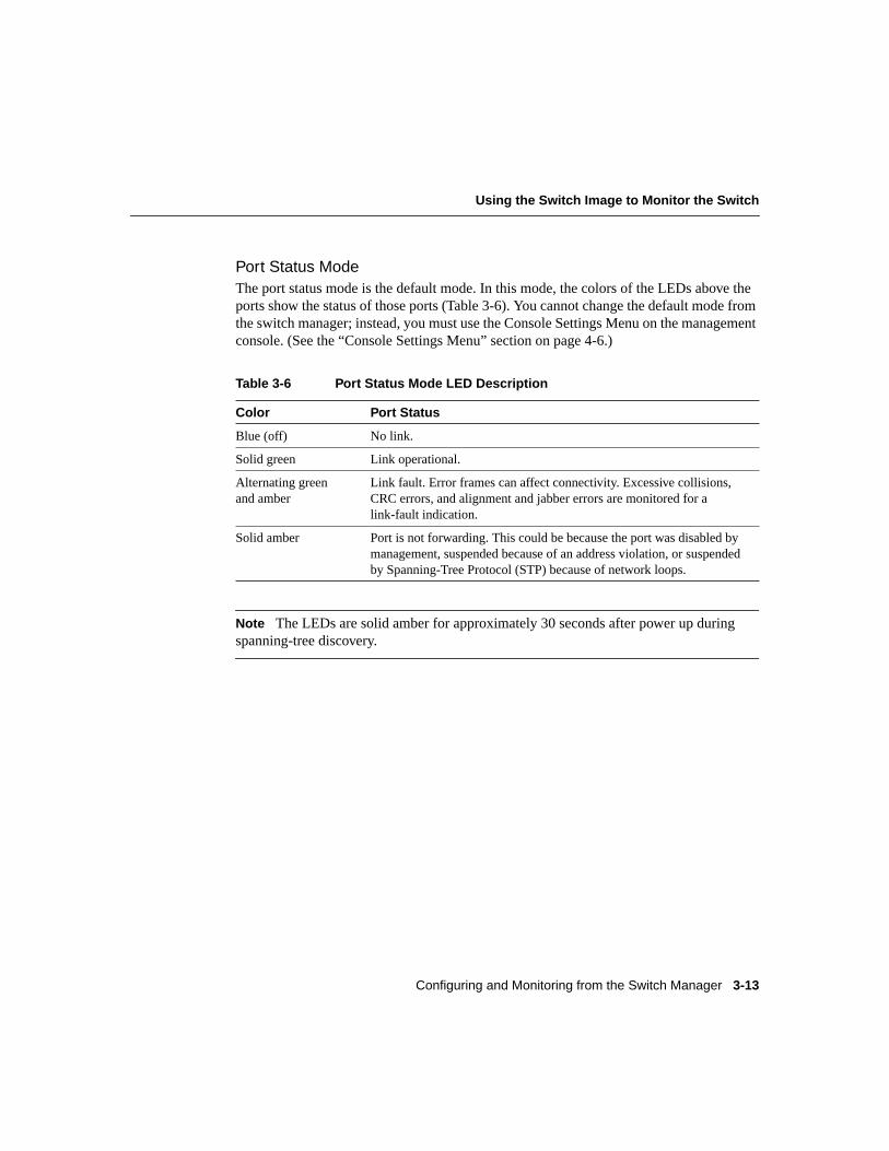
Port Status ModeThe port status mode is the default mode. In this mode, the colors of the LEDs above theports show the status of those ports (Table 3-6). You cannot change the default mode fromthe switch manager; instead, you must use the Console Settings Menu on the managementconsole. (See the “Console Settings Menu” section on page 4-6.)
Note The LEDs are solid amber for approximately 30 seconds after power up duringspanning-tree discovery.
Table 3-6 Port Status Mode LED Description
Color Port Status
Blue (off) No link.
Solid green Link operational.
Alternating greenand amber
Link fault. Error frames can affect connectivity. Excessive collisions,CRC errors, and alignment and jabber errors are monitored for alink-fault indication.
Solid amber Port is not forwarding. This could be because the port was disabled bymanagement, suspended because of an address violation, or suspendedby Spanning-Tree Protocol (STP) because of network loops.
Assigning or Changing Basic Switch Information
Catalyst 1900 Series Installation and Configuration Guide3-14
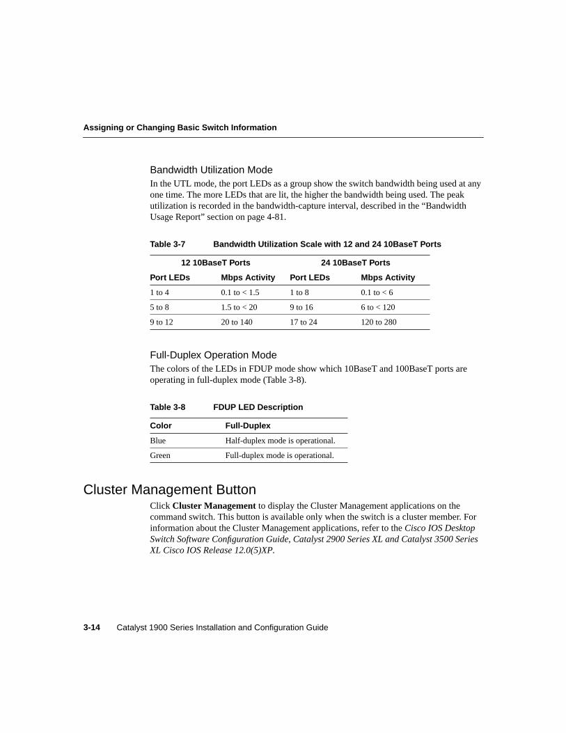
Bandwidth Utilization ModeIn the UTL mode, the port LEDs as a group show the switch bandwidth being used at anyone time. The more LEDs that are lit, the higher the bandwidth being used. The peakutilization is recorded in the bandwidth-capture interval, described in the “BandwidthUsage Report” section on page 4-81.
Full-Duplex Operation ModeThe colors of the LEDs in FDUP mode show which 10BaseT and 100BaseT ports areoperating in full-duplex mode (Table 3-8).
Cluster Management ButtonClick Cluster Management to display the Cluster Management applications on thecommand switch. This button is available only when the switch is a cluster member. Forinformation about the Cluster Management applications, refer to theCisco IOS DesktopSwitch Software Configuration Guide, Catalyst 2900 Series XL and Catalyst 3500 SeriesXL Cisco IOS Release 12.0(5)XP.
Table 3-7 Bandwidth Utilization Scale with 12 and 24 10BaseT Ports
12 10BaseT Ports 24 10BaseT Ports
Port LEDs Mbps Activity Port LEDs Mbps Activity
1 to 4 0.1 to < 1.5 1 to 8 0.1 to < 6
5 to 8 1.5 to < 20 9 to 16 6 to < 120
9 to 12 20 to 140 17 to 24 120 to 280
Table 3-8 FDUP LED Description
Color Full-Duplex
Blue Half-duplex mode is operational.
Green Full-duplex mode is operational.
Configuring and Monitoring from the Switch Manager 3-15
Link to Telnet to the Management Console
Link to Telnet to the Management ConsoleClick Telnet to open a Telnet session on the management console. At the prompt, enter theswitch password or, if applicable, the command-switch password.
Links to Cisco Systems ResourcesThe Home Page provides these links to connect to Cisco Systems resources:
• Click Cisco Connection Online (CCO) to display the CCO home page(www.cisco.com), which contains links to the support sites for downloading the latestsoftware and displaying the latest Cisco documentation.
• Click Technical Assistance Center (TAC) to send e-mail to TAC ([email protected]).You can also phone TAC at 800-553-2447 or 408-526-7209.
• Click HTML Interface Development Group to send e-mail to the switch managerdevelopment group ([email protected]).
Changing the Port SettingsYou can change the settings of the 10- and 100-Mbps ports. To display the PortManagement Page (Figure 3-3), clickPORT on the menu bar, or click the port on theswitch image.
Changing the Port Settings
Catalyst 1900 Series Installation and Configuration Guide3-16
Figure 3-3 Port Management Page
2657
3
Set the portto use or notuse ECC tohelp reducecongestionon the switch.
Set the port as able or unableto transmit and receive data.Displays the current port status.
Set the duplex mode of the port to half orfull duplex. Displays the current duplex mode.
Set the port to forward or not forward unicast andmulticast packets with unknown MAC addresses.
Use up to 60 characters toname or describe the port.
Displays the statisticsfor the port.
10.1.126.351
enabled
enabled
enabled Half duplex
enabled
HOME PORT ADDRESS CGMPSNMP STP CDP SPAN CONSOLE STATISTICS SYSTEM
Configuring and Monitoring from the Switch Manager 3-17
Enabling or Disabling a Port
Note The AUI port settings are displayed in the 10BaseT Ports Table, where the AUI portis port 13 on a 12-port switch or port 25 on a 24-port switch.
Enabling or Disabling a Port
Note You access the switch manager from a management station that is connected to oneof the switch ports. Therefore, make sure that you do not disable or otherwise misconfigurethe port through which you are communicating with the switch. You might want to writedown the port number to which you are connected. Make changes to the switch IPinformation with care.
By default, all ports are enabled to transmit and receive data. To disable a port:
Step 1 Deselect theEnable check box in the Status: Requested/Actual column.
Step 2 Click Apply.
A linkDown trap is sent to the management station if you configured an SNMPmanager.
Step 3 Click Home to display the switch image. The port LED for a disabled port isamber.
To re-enable a port:
Step 1 Select theEnable check box in the Status: Requested/Actual column.
Step 2 Click Apply.
A linkUp trap is sent to the management station if you configured an SNMPmanager.
Step 3 Click Home to display the switch image. If the enabled port is connected to adevice, the port LED is green; otherwise, it is blue.
Changing the Port Settings
Catalyst 1900 Series Installation and Configuration Guide3-18
Port StatusThe Status: Requested/Actual column also displays the port status in the gray area belowtheEnable check box. Security violations, management intervention, or actions of theSpanning-Tree Protocol (STP) can change the port status. No packets are forwarded to orfrom a disabled or suspended port. However, suspended ports do monitor incoming packetsto look for an activating condition. For example, when a linkbeat returns, a port suspendedfor no linkbeat returns to the enabled state.
Each port is always in one of the states listed in Table 3-9.
Table 3-9 Port Status Descriptions
Port Status Description
Enabled Port can transmit and receive data.
Disabled-mgmt Port is disabled by management action. Port must be manuallyre-enabled.
Suspended-no-linkbeat Port is suspended because of no linkbeat. This is usually because theattached station is disconnected or powered-down. Portautomatically returns to enabled state when the condition causing thesuspension is removed.
Suspended-jabber Port is suspended because attached station is jabbering. Portautomatically returns to enabled state when the condition causing thesuspension is removed.
Suspended-violation Port is suspended because of an address violation. Port automaticallyreturns to enabled state when the condition causing the suspension isremoved.
Disabled-self-test Port is disabled because it failed a self-test.
Disabled-violation Port is disabled because of an address violation. Port must bemanually enabled.
Reset Port is in the reset state.
Configuring and Monitoring from the Switch Manager 3-19
Changing the Port Duplex Mode
Changing the Port Duplex ModeThe default duplex mode depends on the port type:
• Half duplex is the default for the 10-Mbps ports and the 100-Mbps fiber-optic ports.
• Autonegotiate is the default for the 100BaseTX ports.
To change the port duplex mode:
Step 1 Selecthalf duplex, full duplex, full duplex with flow control , orautonegotiate from the Duplex Mode: Requested/Actual drop-down list.
The default for the 10-Mbps ports and the 100-Mbps fiber-optic ports is halfduplex. The default for the 100BaseTX ports is autonegotiate.
Note Thefull duplex with flow control option is available only on the100-Mbps ports. Theautonegotiateoption is available only on the 100BaseTXports, not on the 10BaseT ports or the 100-Mbps fiber-optic ports.
Note After you select Auto-negotiate as the 100BaseTX port duplex modefrom this page and clickApply, “Auto-negotiate” displays in the Actual fieldwhile the switch and the other device negotiate the duplex mode. ClickPort onthe switch manager menu bar to display the final duplex state of the port.
Step 2 Click Apply.
Step 3 Click Home to display the switch image.
Step 4 Click theMode button until the FDUP LED lights. If the port LED is blue (off),the port is running in half duplex. If the port LED is green, the port is running infull duplex.
Changing the Port Settings
Catalyst 1900 Series Installation and Configuration Guide3-20
Full-Duplex OperationFull-duplex operation is the simultaneous transmission of data in both directions across alink. For example, a 100-Mbps port operating in full-duplex mode can provide up to200 Mbps of bandwidth across the switched link.
Note Both ends of the link must be configured for full-duplex operation. Because hubsoperate only at half duplex, a full-duplex port on the switch cannot be connected to a hub.
Flow ControlFlow control is a function whereby the transmitting station does not send data or controlinformation faster than the receiving station can accept it. This prevents the loss of outgoingpackets during transmission. If the switch is transmitting packets faster than the attacheddevice can receive and process them, the attached device sends pause-control frames whenits port buffer becomes full. When you use thefull-duplex with flow control option on a100-Mbps port, the switch port responds to the pause-control frames sent from the attacheddevice. The switch holds subsequent transmissions in the port queue for the time specifiedin the pause-control frame. When no more pause-control frames are received, or when thedefault time specified has passed, the switch resumes transmitting frames through the port.
Note Although the Catalyst 1900 switches do not generate pause-control frames, theswitches do respond appropriately to pause-control frames generated by other devices.
Note Flow control on full-duplex ports is only available on the 100-Mbps ports. Forinformation about using thehalf-duplex back pressureoption on the 10-Mbps ports, seethe “Half-Duplex Back Pressure on 10-Mbps Ports” section on page 3-75.
AutonegotiationWhen you use theautonegotiateoption on a 100BaseTX port, it automatically configuresfor full-duplex operation if the connected device also supports full duplex. If the attacheddevice does not autonegotiate, the port automatically configures itself to half duplex.
Note Duplex negotiation is only available on the 100BaseTX ports.
Configuring and Monitoring from the Switch Manager 3-21
Enabling or Disabling Flooding of Unknown MAC Addresses
Enabling or Disabling Flooding of Unknown MAC AddressesBy default, all switch ports are enabled to forward unicast and multicast packets withunknown destination Media Access Control (MAC) addresses. You can enable or disableflooding on a per-port basis.
A unicast packetis information addressed to one recipient from one sender. This type oftraffic typically comprises the bulk of traffic on an Ethernet LAN. Amulticast packet isinformation sent to multiple recipients from one sender. This lightens the load on the senderand on the network because only one data stream is sent, rather than one per recipient. Abroadcast packetis information sent to all nodes within a single network segment and canbe a major source of congestion.
The switch forwards each unicast or multicast packet it receives according to the entriesstored in the switch content-addressable memory (CAM) table. The table entries aremappings of the MAC addresses of destination end-stations and of the associated switchports through which incoming packets are forwarded to those destination end-stations.
• If the destination address is not listed in the table, the switch forwards the packet to allswitch ports except the port from which the packet was received. When the destinationend-station replies, the switch adds the MAC address and its associated forwarding portto the table.
• If the associated port is the same port on which the packet is received, the packet is notforwarded (filtered).
Flooding is the forwarding of unicast or multicast packets with unknown destinationaddresses to all the switch ports. (A broadcast packet is always forwarded [flooded] to allports.) Flooding adds traffic on the switch ports. In some configurations, flooding could beunnecessary. For example, there are no unknown destinations on switch ports with onlystatically assigned addresses or single stations attached. In this case, you can disableflooding on these ports.
You can assign a network port to which all unknown unicast addresses are forwarded. Formore information, see the “Network Port” section on page 3-75.
The switch can store up to 1024 address entries in memory.
For more information about address management, see the “Managing the Switch AddressTables” section on page 3-26. For information about multicast packet control, see the“Managing Multicast Packets with CGMP” section on page 3-78. For information aboutbroadcast packet control, see the “Broadcast Storm Control” section on page 3-76.
Changing the Port Settings
Catalyst 1900 Series Installation and Configuration Guide3-22
To disable flooding on a port:
Step 1 Deselect theunicast or multicast check box for the port.
Step 2 Click Apply.
To enable flooding on a port:
Step 1 Select theunicast or multicast check box for the port.
Step 2 Click Apply.
Enabling or Disabling ECC on the 100-Mbps PortsBy default, enhanced congestion control (ECC) is disabled on all 100-Mbps ports. Thisoption reduces congestion on the switch and keeps the switch from dropping framesbecause of full transmit queues. The ECC option can be enabled on half-duplex ports andcan be configured on a per-port basis on the 100-Mbps ports.
For information about ECC on the 10-Mbps ports, see the “ECC on 10-Mbps Ports” sectionon page 3-76. ECC on the 10-Mbps ports is set on a global basis, not on a per-port basis.
To enable ECC on a 100-Mbps port:
Step 1 Select one of the following modes from the Enhanced Congestion Controldrop-down list.
• Adaptive—Causes the port to operate under the ECC Disabled setting if thetransmit queue is not full. If the queue is full, the port uses the ECCAggressive setting.
• Disabled—Causes the port to operate under the standard IEEE 802.3 backoffalgorithm for retransmitting frames.
• Moderately Aggressive—Causes the port to use a modified backoffalgorithm to more aggressively retransmit frames and empty the queue.
• Aggressive—Is the highest acceleration rate configurable for ECC. The portuses a modified backoff algorithm to more aggressively retransmit framesand empty the queue than when set at ECC Moderately Aggressive.
Step 2 Click Apply.
Configuring and Monitoring from the Switch Manager 3-23
Assigning or Changing a Port Name or Description
Assigning or Changing a Port Name or DescriptionTo assign a name or description to a port:
Step 1 In the Port Name/Description column, enter the port name or a description(up to 60 characters).
Step 2 Click Apply.
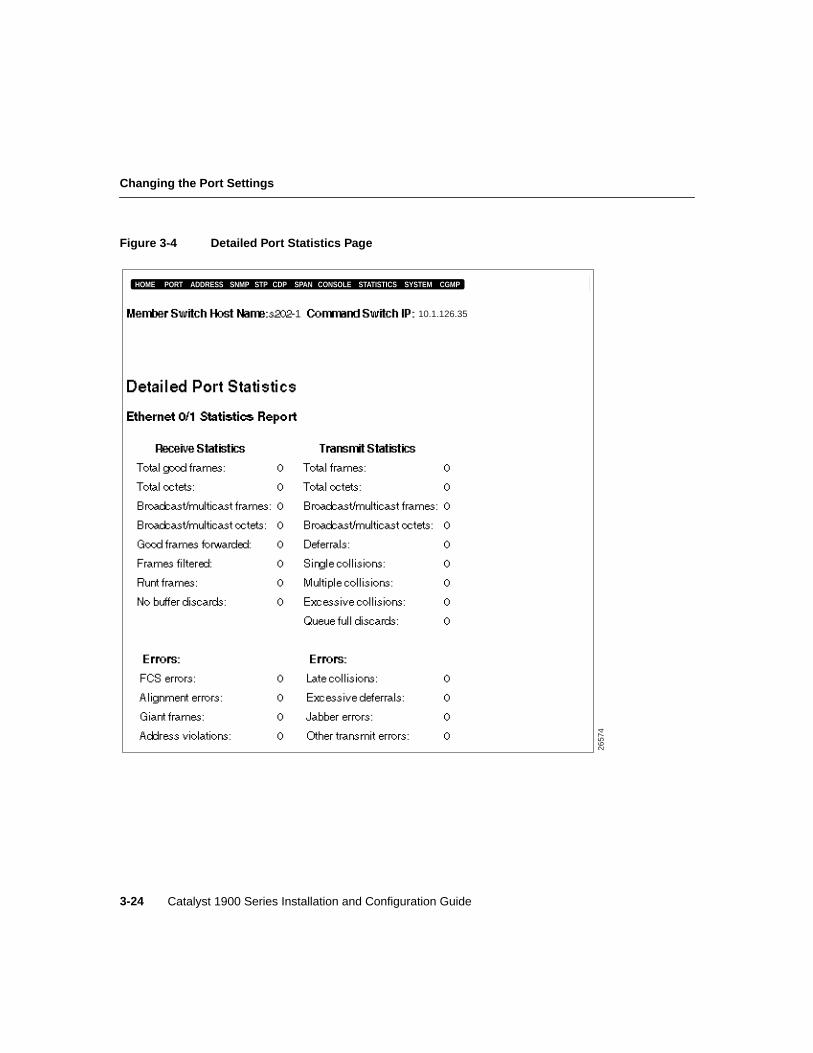
Detailed Port StatisticsThe Detailed Port Statistics Page (Figure 3-4) displays the receive and transmit statistics forthe port you select. You can use this page to help identify performance or connectivityproblems, which are listed under the Errors area of the page. For example, Frame CheckSequence (FCS) and alignment errors could be the result of cabling problems such as thefollowing:
• Cabling distance exceeded
• Split pairs
• Defective patch-panel ports
• Wrong cable type
• Misconfigured full-duplex connection
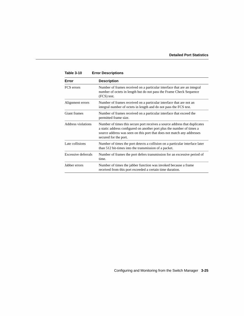
To display this page, clickView... for a particular port on the Port Management Page. Theerrors are described in Table 3-10.
Changing the Port Settings
Catalyst 1900 Series Installation and Configuration Guide3-24
Figure 3-4 Detailed Port Statistics Page
2657
4
10.1.126.35
HOME PORT ADDRESS CGMPSNMP STP CDP SPAN CONSOLE STATISTICS SYSTEM
1
Configuring and Monitoring from the Switch Manager 3-25
Detailed Port Statistics
Table 3-10 Error Descriptions
Error Description
FCS errors Number of frames received on a particular interface that are an integralnumber of octets in length but do not pass the Frame Check Sequence(FCS) test.
Alignment errors Number of frames received on a particular interface that are not anintegral number of octets in length and do not pass the FCS test.
Giant frames Number of frames received on a particular interface that exceed thepermitted frame size.
Address violations Number of times this secure port receives a source address that duplicatesa static address configured on another port plus the number of times asource address was seen on this port that does not match any addressessecured for the port.
Late collisions Number of times the port detects a collision on a particular interface laterthan 512 bit-times into the transmission of a packet.
Excessive deferrals Number of frames the port defers transmission for an excessive period oftime.
Jabber errors Number of times the jabber function was invoked because a framereceived from this port exceeded a certain time duration.
Managing the Switch Address Tables
Catalyst 1900 Series Installation and Configuration Guide3-26
Managing the Switch Address TablesThe switches use source address tables (filters) to efficiently forward packets between theswitch ports. Address filtering applies only to incoming (received) traffic on the switch. Thesource address tables list the source addresses (sending end-stations) and the associatedswitch port(s) through which packets are forwarded to the destination end-stations.
Packets with static addresses are usually received on any source port. The switch alsosupports source-port filtering on unicast and multicast addresses. This enhanced filteringenables the switch to only forward packets from source addresses when they are receivedon specified switch ports. These source addresses are referred to asrestricted staticaddresses.
The switch can store up to 1024 address entries in memory.
For additional traffic control options, see the following sections:
• “Enabling or Disabling Flooding of Unknown MAC Addresses” section on page 3-21
• “Switch Performance and Flooding and Traffic Control” section on page 3-73
• “Broadcast Storm Control” section on page 3-76
• “Managing Multicast Packets with CGMP” section on page 3-78
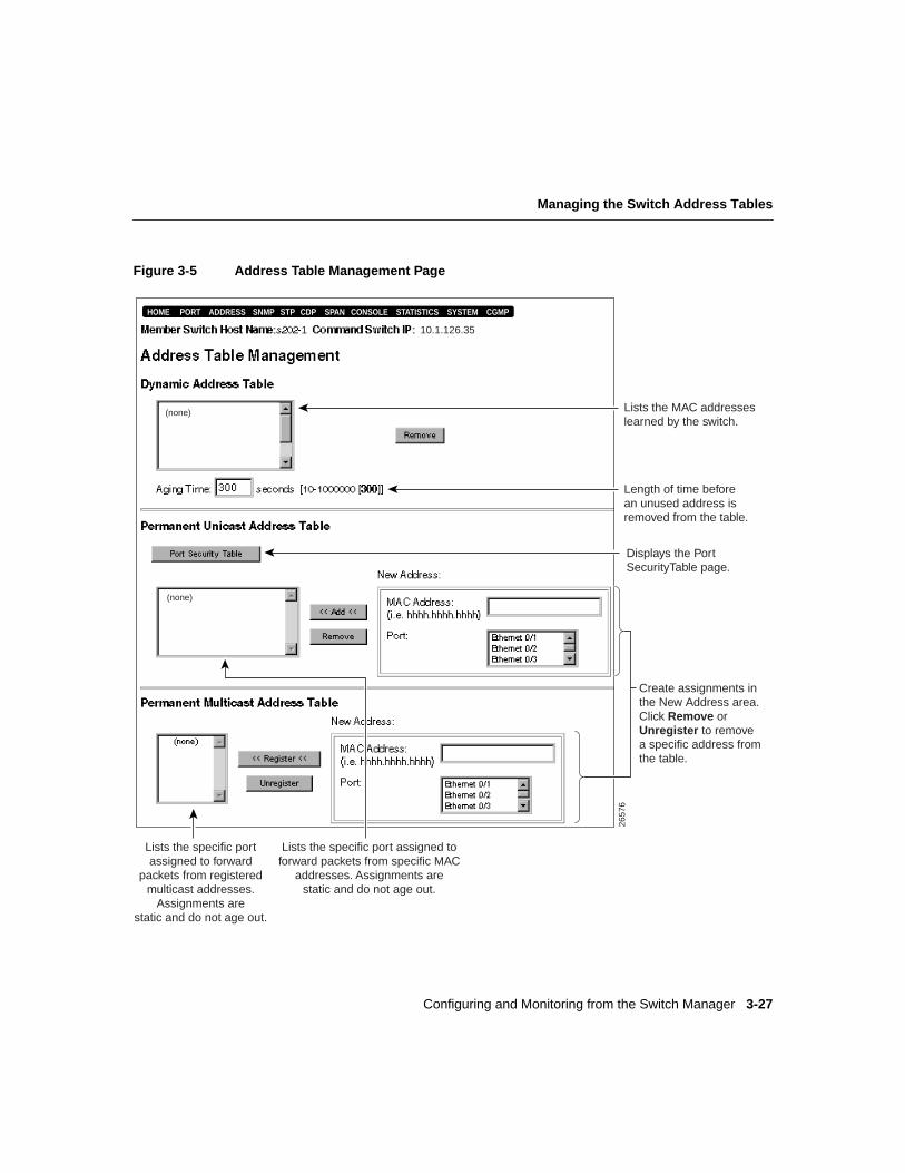
To display the Address Table Management Page (Figure 3-5), clickAddress on the menubar.
Configuring and Monitoring from the Switch Manager 3-27
Managing the Switch Address Tables
Figure 3-5 Address Table Management Page
2657
6
Lists the MAC addresseslearned by the switch.
Displays the PortSecurityTable page.
Lists the specific port assigned toforward packets from specific MAC
addresses. Assignments arestatic and do not age out.
Length of time beforean unused address isremoved from the table.
Lists the specific portassigned to forward
packets from registeredmulticast addresses.
Assignments arestatic and do not age out.
Create assignments in the New Address area. Click Remove or Unregister to removea specific address from the table.
(none)
(none)
10.1.126.35
HOME PORT ADDRESS CGMPSNMP STP CDP SPAN CONSOLE STATISTICS SYSTEM
1
Managing the Switch Address Tables
Catalyst 1900 Series Installation and Configuration Guide3-28
Dynamic Address TableThe switch provides dynamic addressing by learning the source MAC address of eachpacket received on each switch port and then adding the address and its associatedforwarding switch port number to the Dynamic Address Table. As end-stations are addedor removed from the network, the switch updates the table, adding new entries andremoving unused ones.
To delete a specific entry from the Dynamic Address Table:
Step 1 Select the entry you want to delete.
Step 2 Click Remove.
Changing the Address Aging TimeAs the switch reaches the maximum address limit of 1024 address entries in memory,switch performance can degrade. Address aging helps prevent this by allowing the switchto keep only dynamic addresses that remain active over a specified period of time.
During a topology change, if the Port Fast mode option on the Port Management Page isdisabled, addresses are aged more quickly by using the Forward delay option on theSpanning-Tree Management Page. When the topology stabilizes, the address-aging valueagain takes effect.
To assign the length of time the switch stores an inactive entry, after which it is removedfrom the table:
Step 1 Enter the number of seconds (10 to 1000000; where 1000000 seconds isapproximately 11 1/2 days) in the Aging Time field. The default is 300 seconds(5 minutes).
This value applies to all dynamic addresses in the Dynamic Address Table.
Step 2 Click Apply.
Configuring and Monitoring from the Switch Manager 3-29
Permanent Unicast Address Table
Permanent Unicast Address TableThe entries in the Permanent Unicast Address Table allow MAC addresses to bepermanently associated with a switch port. Unlike the Dynamic Address Table, the entriesin the Permanent Unicast Address Table are manually entered orsticky-learned. (See the“Securing a Port” section on page 3-33.)
If the address table is full, an error message is generated. You can change the size of theaddress table by using the Port Security Table Page. (See the “Changing the MaximumSecure Address Count” section on page 3-33.) For additional information about portsecurity, see the “Changing the Port Security Table” section on page 3-31.
You can assign a network port to which all unknown unicast addresses are forwarded. Formore information, see the “Network Port” section on page 3-75.
Note Only unicast addresses can be added. An attempt to add a multicast or broadcastaddress generates an error message.
To add a secure address to the Permanent Unicast Address Table:
Step 1 Select a switch port from the New Address scroll list.
Step 2 Enter the source MAC address in the MAC Address field. Use six hexadecimaloctets, spaces are optional (such as hh hh hh hh hh hh or hhhhhhhhhhhh).
Step 3 Click Add.
Static entries do not age out and must be manually removed from the table. To delete anentry from the table:
Step 1 Select the entry you want to delete.
Step 2 Click Remove.
Managing the Switch Address Tables
Catalyst 1900 Series Installation and Configuration Guide3-30
Permanent Multicast Address TableThe entries in the Permanent Multicast Address Table allow multicast addresses to bepermanently associated with the switch port(s) that receive packets destined for thosemulticast addresses. Using the Permanent Multicast Address Table reduces the amount ofmulticast flooding on the switch. Unlike the Dynamic Address Table, the entries in thePermanent Multicast Address Table entries are manually entered.
If the address table is full, an error message is generated. You can change the size of theaddress table by using the Port Security Table Page. (See the “Changing the MaximumSecure Address Count” section on page 3-33.)
For additional information, see the
• “Changing the Port Security Table” section on page 3-31
• “Managing Multicast Packets with CGMP” section on page 3-78
To add a secure address to the Permanent Multicast Address Table:
Step 1 Select a switch port from the New Address scroll list.
Step 2 Enter the multicast MAC address in the MAC Address field. Use sixhexadecimal octets, spaces are optional (such as hh hh hh hh hh hh orhhhhhhhhhhhh).
Step 3 Click Register.
Static entries do not age out and must be manually removed from the table. To delete anentry from the table:
Step 1 Select the entry you want to delete.
Step 2 Click Unregister.
Configuring and Monitoring from the Switch Manager 3-31
Changing the Port Security Table
Changing the Port Security TableYou can use the Port Security Table Page (Figure 3-6) to prevent the switch fromforwarding packets from unauthorized users and to send SNMP traps if security violationsoccur. To display this page, clickPort Security Table from the Address Table ManagementPage.
Managing the Switch Address Tables
Catalyst 1900 Series Installation and Configuration Guide3-32
Figure 3-6 Port Security Table Page
2657
8
Set the port to retain orremove its associationwith all static addresseswhen the port loses link.
Set the port to forward or notforward packets from unauthorizedMAC addresses.
Displays the number of unauthorizedaddresses seen on the secure port.
Set the number of static and learned unicastaddresses associated with the port.
10.1.126.35
HOME PORT ADDRESS CGMPSNMP STP CDP SPAN CONSOLE STATISTICS SYSTEM
1
Configuring and Monitoring from the Switch Manager 3-33
Changing the Port Security Table
Securing a PortBy default, port security is disabled (Security check box is not selected). Secure portsrestrict the use of a switch port to a specific group of source addresses (sendingend-stations). When you assign source addresses to a secure port, the switch does notforward any packets from addresses outside that group.
The source addresses on a secure port are manually assigned (static) orsticky-learned.Sticky-learning takes place when the address table for a secure port does not contain a fullcomplement of static addresses. The port sticky-learns the source address of incomingpackets and automatically assigns them as static addresses.
Note This option must be disabled on the network port. For more information about thenetwork port, see the “Network Port” section on page 3-75.
To enable port security on a port:
Step 1 Select the check box in the Security column for the port.
Step 2 Click Apply.
To disable port security on a port:
Step 1 Deselect the check box in the Security column for the port.
Step 2 Click Apply.
Changing the Maximum Secure Address CountIf the port is not a secure port, the value in the Maximum Secure Addresses field is 0. Asecure port can have from 1 to 132 secure addresses associated with it.
Limiting the number of devices that can connect to a secure port has the followingadvantages:
• Dedicated bandwidth—If the size of the address table is set to 1, the attached device isguaranteed the full 10 Mbps or 100 Mbps of the port.
• Added security—Devices cannot connect to the port without your knowledge.
Note The size of the address table for an unsecured port cannot be modified.
Managing the Switch Address Tables
Catalyst 1900 Series Installation and Configuration Guide3-34
To change the number of addresses to the secure port:
Step 1 Enter a number (1 to 132) in the Maximum Secure Addresses column.
Step 2 Click Apply.
Security Reject CountThe Security Reject Count (SRC) column displays the number of unauthorized addressesseen on the secure port.
Secure ports generate address-security violations under the following conditions:
• The address table of a secure port is full and the address of an incoming packet is notfound in the table.
• An incoming packet has a source address statically assigned to another port.
If a security violation occurs, the port can be suspended or disabled. When a port isdisabled, you must manually re-enable the port. When a port is suspended, it is re-enabledwhen a packet containing a valid address is received. You can also choose to ignore theviolation. You can define the action taken by the switch either by using the SystemManagement Page or by using the MIB objects.
On the following switch manager pages, you can specify the action the switch takes ifpackets with unauthorized addresses arrive on the port:
• On the SNMP Management Page, you can enable or disable trap generation.
• On the System Management Page, you can assign the switch to ignore, suspend, ordisable the port if an address violation occurs. (For more information, see the “ActionUpon Address Violations” section on page 3-74.)
Configuring and Monitoring from the Switch Manager 3-35
Changing the SNMP Settings
Clearing Addresses on LinkDownBy default, the secure port keeps its association with all static addresses even if it loses link(Clear Addresses on LinkDowncheck box is not selected). You can enable a secure portto clear its address associations on linkDown.
Note This option is applicable only to secure ports (Security check box is selected).
To enable the secure port to clear its address table on linkDown:
Step 1 Select the check box in the Clear Addresses on LinkDown column for the port.
Step 2 Click Apply.
To disable the secure port from clearing its address table on linkDown:
Step 1 Deselect the check box in the Clear Addresses on LinkDown column for theport.
Step 2 Click Apply.
Changing the SNMP SettingsSimple Network Management Protocol (SNMP) provides the means to manage andmonitor the switch through the Management Information Base (MIB) objects. Additionalinformation about SNMP and MIB objects is in the “Simple Network ManagementProtocol” section on page 1-24 and the “Accessing MIB Files” section on page 2-44.
For information about how the command switch uses SNMP to manage the switch in thecluster, refer to theCisco IOS Desktop Switch Software Configuration Guide,Catalyst 2900 Series XL and Catalyst 3500 Series XL Cisco IOS Release 12.0(5)XP.
To display the SNMP Management Page (Figure 3-7), clickSNMP on the menu bar.
Changing the SNMP Settings
Catalyst 1900 Series Installation and Configuration Guide3-36
Figure 3-7 SNMP Management Page
10.1.126.35
publicpublic @es
privateprivate @es
HOME PORT ADDRESS CGMPSNMP STP CDP SPAN CONSOLE STATISTICS SYSTEM
2658
0
Passwords that allow read-only (Get requests) access to the switch MIB-object information. When the switch is a cluster member, the last string is from the command switch. Do not use "@es" in the strings you define.
Passwords that allow read-write (Get requests) access to the switch MIB-object information. When the switch is a cluster member, the last string is from the command switch. Do not use "@es" in the strings you define.
Management stations that canreceive SNMP traps (alerts of certain events) generated by the switch. Use the traps to monitor the switch.
Management stations that can issue write requests to changethe switch configurationsettings through the MIB variables. Available when the switch has its own IP address.
Set the switch to generate ornot generate these types of traps.
Configuring and Monitoring from the Switch Manager 3-37
Assigning or Changing the SNMP Read Community Strings
Assigning or Changing the SNMP Read Community StringsThe default for the first Read community string is public. You can assign up to fourcommunity strings to serve as passwords that enable the switch to validate SNMP read(Get) requests from a management station.
When the switch joins a cluster, the command switch propagates its first Read communitystring as the last Read community string for the member switch. If the joiningCatalyst 1900 switch already has four Read community strings, the command switchoverrides that fourth community string with its own first community string. When theswitch leaves the cluster, the command-switch community string is deleted.
The command-switch string contains up to 27 characters and a suffix “@esNN” whereNNis the member switch number.
Caution Do not use “@es” in the community strings you define for the switch. When theswitch joins a cluster, any community string containing “@es” is deleted.
To add or change a SNMP Read community string:
Step 1 Enter up to 32 characters in the Read Community String field. The default forthe first Read community string is public.
Step 2 Click Add.
To remove a SNMP Read community string:
Step 1 Select the community string from the Current list.
Step 2 Click Remove.
Changing the SNMP Settings
Catalyst 1900 Series Installation and Configuration Guide3-38
Assigning or Changing the SNMP Write Community StringsThe default for the first Write community string is private. You can assign up to fourcommunity strings to serve as passwords that enable the switch to validate SNMPread-write (Set) requests from a management station. The write managers you assign to theswitch can use any of the switch Write community strings.
When the switch joins a cluster, the command switch assigns its first Write communitystring as the last Write community string for the member switch. If the joiningCatalyst 1900 switch already has four Write community strings, the command switchoverrides that fourth community string with its own first community string. When theswitch leaves the cluster, the command-switch community string is deleted.
The command-switch string contains up to 27 characters and a suffix “@esNN” whereNNis the member switch number.
Caution Do not use “@es” in the community strings you define for the switch. When theswitch joins a cluster, any community string containing “@es” is deleted.
To add or change a SNMP Write community string:
Step 1 Enter up to 32 characters in the Write Community String field. The default forthe first Write community string is private.
Step 2 Click Add.
To remove a SNMP Write community string:
Step 1 Select the community string from the Current list.
Step 2 Click Remove.
Configuring and Monitoring from the Switch Manager 3-39
Assigning or Changing Trap Managers
Assigning or Changing Trap ManagersA trap manager, or trap client, is an SNMP management station that receives traps, whichare the system alerts generated by the switch. If no trap manager is defined, no traps areissued.
You can assign up to four trap managers and their accompanying community strings. A trapmanager can use its accompanying community string only; it cannot use the communitystring of another trap manager.
Trap manager settings can be configured from the switch or, if the switch is a clustermember, from the command switch.
After you have assigned the trap manager(s), the switch generates, by default, the followingtraps:
• warmStart
• coldStart
• linkDown
• linkUp
• authenticationFailure
• newRoot
• topologyChange
• logonIntruder
• switchDiagnostic
• addressViolation
• broadcastStormControl
• rpsFailed
• ipAddressChange
For more information about traps, see the “Simple Network Management Protocol” sectionon page 1-24 and the “Accessing MIB Files” section on page 2-44.
Changing the SNMP Settings
Catalyst 1900 Series Installation and Configuration Guide3-40
To assign a trap manager and its community string:
Step 1 In the IP Address field, enter the IP address of the SNMP management stationthat can issue trap requests to the switch. Use dotted quad format(nnn.nnn.nnn.nnn).
If the switch is connected to a Domain Name System (DNS) server, you canenter the name of the trap manager instead.
Step 2 Enter a community string (up to 32 characters) in the Trap Manager CommunityString field.
Step 3 Click Add.
To remove a trap manager:
Step 1 Select the manager from the Current list.
Step 2 Click Remove.
Authentication Trap GenerationBy default, authentication trap generation is enabled (Enable Authentication TrapGeneration check box is selected). This option enables the switch to generateauthentication traps, which alert a management station of SNMP requests not accompaniedby a valid community string.
Note Even if this option is enabled, no traps are generated if no trap manager addresses ornames are assigned. (See the “Assigning or Changing Trap Managers” section onpage 3-39.)
To disable authentication trap generation:
Step 1 Deselect theEnable check box.
Step 2 Click Apply.
Configuring and Monitoring from the Switch Manager 3-41
Assigning or Changing Trap Managers
LinkUp/LinkDown Trap GenerationBy default, linkUp/linkDown trap generation is enabled (Enable LinkUp/LinkDownTrap Generation check box is selected). This option enables the switch to generatelinkDown traps when a port is suspended or disabled for any of these reasons:
• Secure address violation (address mismatch or duplication)
• Network connection error (loss of linkbeat or jabber error)
• Port disabled by management action
The switch generates linkUp traps when a port is enabled for any of these reasons:
• Presence of linkbeat
• Management intervention
• Recovery from an address violation or any other error
Note No more than one trap is sent every 5 seconds per port. The last trap generated in the5-second interval is the one sent.
To disable linkUp/linkDown trap generation:
Step 1 Deselect theEnable check box.
Step 2 Click Apply.
Broadcast Storm Trap GenerationBy default, broadcast storm trap generation is disabled (Enable Broadcast Storm TrapGeneration check box is not selected). When this option is enabled, the switch generatesSNMP alerts when the broadcast threshold is exceeded. The alert generated is thetrapbroadcastStorm. A trap is generated every 30 seconds.
For information about broadcast storm control, see the “Broadcast Storm Control” sectionon page 3-76.
To enable broadcast storm trap generation:
Step 1 Select theEnable check box.
Step 2 Click Apply.
Changing the SNMP Settings
Catalyst 1900 Series Installation and Configuration Guide3-42
Address Violation Trap GenerationBy default, address violation trap generation is enabled (Enable Address Violation TrapGenerationcheck box is selected). This option enables the switch to generate SNMP alertsif an address violation occurs.
To disable address violation trap generation:
Step 1 Deselect theEnable check box.
Step 2 Click Apply.
Assigning or Changing Write ManagersA write manager is an SNMP management station that can issue write requests to theswitch. You can assign up to four write managers. The switch allows write requests fromonly the specified write managers or from the command switch. The write managers youassign can use any of the switch Write community strings.
Caution If no write manager is assigned to the switch, any management station canmodify the switch MIB objects.
Note The write manager option is not available from the command switch. To use thisoption, use the SNMP Management Page or the Network Management (SNMP) WRITEConfiguration Menu.
To assign a write manager:
Step 1 Enter the IP address in the IP Address field. Use dotted quad format(nnn.nnn.nnn.nnn).
If the switch is connected to a DNS server, you can enter the name of the writemanager instead.
Step 2 Click Add.
To remove a write manager:
Step 1 Select the manager from the Current list.
Step 2 Click Remove.
Configuring and Monitoring from the Switch Manager 3-43
Changing the Spanning-Tree Protocol Settings
Changing the Spanning-Tree Protocol SettingsThe Spanning-Tree Protocol (STP) constructs network topologies that do not contain loops.When the network configuration changes, STP transparently reconfigures bridges andswitches to avoid the creation of loops. STP avoids loops by placing ports in a forwardingor blocking state and establishes redundant paths (in the event of lost connections).
The following are two examples for using STP:
• Redundant connectivity—You can create a redundant backbone with STP byconnecting two of the ports on a switch to another device or to two different devices.STP automatically disables one port but enables it if the other port is lost. If one link ishigh-speed and the other low-speed, STP uses the high-speed link. If the speed of thetwo links is the same, the port priority and port ID are added together, and the link withthe lowest value is disabled.
• Accelerated address aging—Dynamic addresses are aged and dropped from the addresstable after a configurable period of time. The default for aging dynamic addresses is5 minutes. However, a reconfiguration of the spanning tree can cause many stationlocations to change. Because this could mean that many stations are unreachable for5 minutes or more, the address-aging time is accelerated so that station addresses can bedropped from the address table and then relearned. The accelerated-aging value is thesame as the forward-delay parameter value when STP reconfigures.
Changing the Spanning-Tree Protocol Settings
Catalyst 1900 Series Installation and Configuration Guide3-44
A separate spanning-tree instance runs on each bridge group, and each bridge groupparticipates in a separate spanning tree. Each switch in a spanning tree adopts the Hello,Max age, and Delay parameters of the root bridge regardless of how it is configured.Overlapping ports (ports that belong to more than one bridge group) participate in allspanning trees to which they belong. All ports on the switch support STP, and STP ismanaged through the standard Bridge MIB.
Note From the switch manager, you can only configure the STP settings for bridgegroup 1 (the management bridge group) or VLAN 1 (the management VLAN).
Overlapping ports should be connected to end nodes only, not to other bridges. To configurethe STP settings for other bridge groups on the switch, use the Spanning Tree ConfigurationMenu on the management console.
For more information about bridge groups and to configure bridge groups, see the BridgeGroup Configuration Menu and the “Spanning Tree Configuration Menu” on page 31. Forinformation about VLANs, refer to theCatalyst 1900 Series and Catalyst 2820 SeriesEnterprise Edition Software Configuration Guide.
To display the Spanning-Tree Management Page (Figure 3-8), clickSTP on the menu bar.
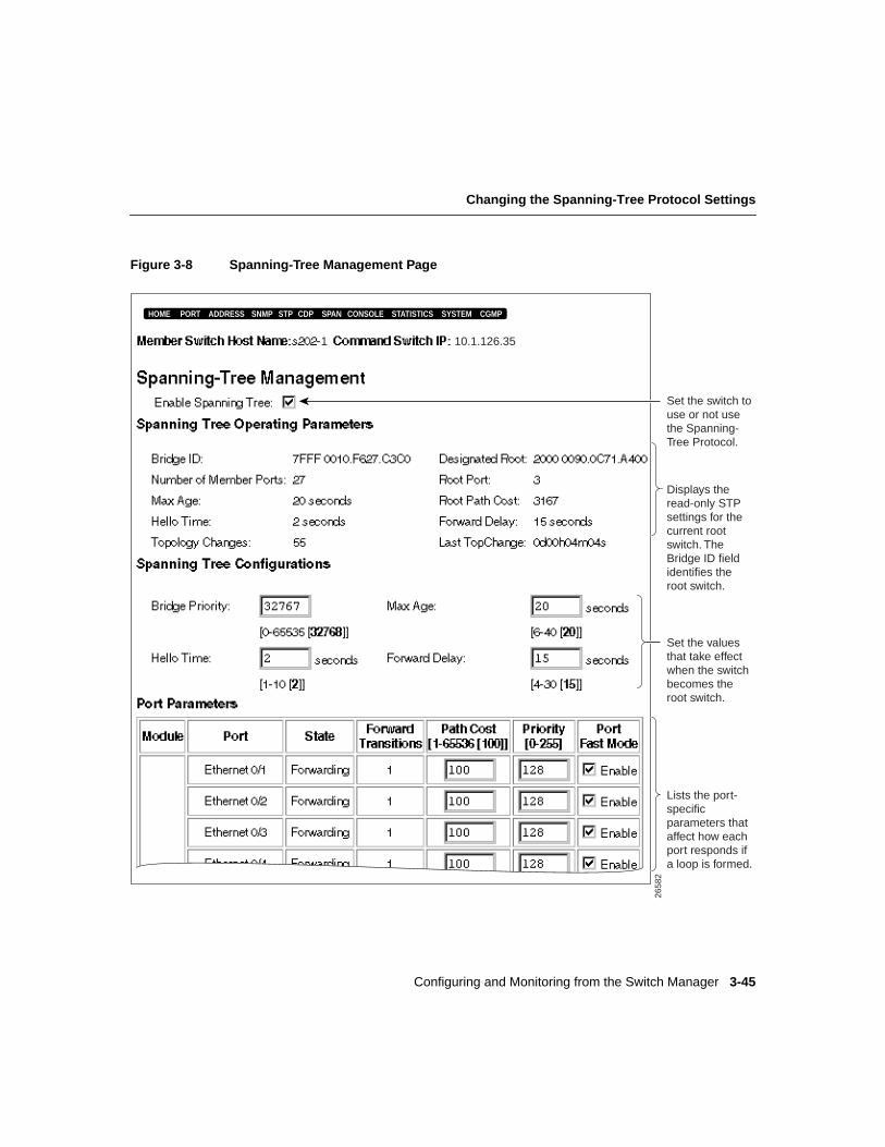
Configuring and Monitoring from the Switch Manager 3-45
Changing the Spanning-Tree Protocol Settings
Figure 3-8 Spanning-Tree Management Page
10.1.126.35
HOME PORT ADDRESS CGMPSNMP STP CDP SPAN CONSOLE STATISTICS SYSTEM
Lists the port-specific parameters that affect how each port responds if a loop is formed.
1
Set the values that take effect when the switchbecomes the root switch.
Displays the read-only STP settings for the current root switch. TheBridge ID field identifies the root switch.
Set the switch to use or not use the Spanning-Tree Protocol.
2658
2
Changing the Spanning-Tree Protocol Settings
Catalyst 1900 Series Installation and Configuration Guide3-46
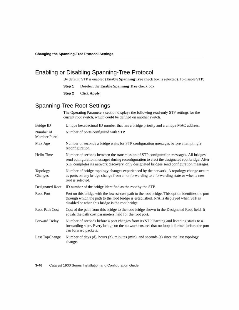
Enabling or Disabling Spanning-Tree ProtocolBy default, STP is enabled (Enable Spanning Treecheck box is selected). To disable STP:
Step 1 Deselect theEnable Spanning Tree check box.
Step 2 Click Apply.
Spanning-Tree Root SettingsThe Operating Parameters section displays the following read-only STP settings for thecurrent root switch, which could be defined on another switch.
Bridge ID Unique hexadecimal ID number that has a bridge priority and a unique MAC address.
Number ofMember Ports
Number of ports configured with STP.
Max Age Number of seconds a bridge waits for STP configuration messages before attempting areconfiguration.
Hello Time Number of seconds between the transmission of STP configuration messages. All bridgessend configuration messages during reconfiguration to elect the designated root bridge. AfterSTP completes its network discovery, only designated bridges send configuration messages.
TopologyChanges
Number of bridge topology changes experienced by the network. A topology change occursas ports on any bridge change from a nonforwarding to a forwarding state or when a newroot is selected.
Designated Root ID number of the bridge identified as the root by the STP.
Root Port Port on this bridge with the lowest-cost path to the root bridge. This option identifies the portthrough which the path to the root bridge is established. N/A is displayed when STP isdisabled or when this bridge is the root bridge.
Root Path Cost Cost of the path from this bridge to the root bridge shown in the Designated Root field. Itequals the path cost parameters held for the root port.
Forward Delay Number of seconds before a port changes from its STP learning and listening states to aforwarding state. Every bridge on the network ensures that no loop is formed before the portcan forward packets.
Last TopChange Number of days (d), hours (h), minutes (min), and seconds (s) since the last topologychange.
Configuring and Monitoring from the Switch Manager 3-47
Changing the Spanning-Tree Options for the Switch
Changing the Spanning-Tree Options for the SwitchThe Spanning Tree Configuration section displays a list of STP parameters that this switchwill use when it is the root switch.
Note Modifying the spanning-tree settings causes a temporary loss of connectivity whilethe network reconfigures. STP requires approximately 30 seconds to complete its discoveryof the network, and the switch does not forward packets during this time.
Note For information about VLANs and the Uplink Fast option, refer to theCatalyst 1900Series and Catalyst 2820 Series Enterprise Edition Software Configuration Guide.
To change the STP configuration on this switch:
Step 1 Enable STP if you have previously disabled it:
(a) Select theEnable Spanning Tree check box.
(b) Click Apply.
Note You can slightly improve switch performance by disabling STP.However, disable STP only if you are sure there are no loops in your networktopology. With STP disabled and loops present in the topology, networkperformance is degraded by excessive traffic and indefinite packet duplication.
Step 2 In the Bridge Priority field, enter the value (0 to 65535) used in determining theroot bridge. The bridge with the lowest value has the highest priority and isselected as the root. The default is 32768.
Changing the Spanning-Tree Protocol Settings
Catalyst 1900 Series Installation and Configuration Guide3-48
Step 3 In the Hello Time field, enter the number of seconds (1 to 10) between thetransmission of STP configuration messages. The default is 2.
Step 4 In the Max Age field, enter the number of seconds (6 to 40) a switch waits forSTP configuration messages before it attempts a reconfiguration. After thisperiod expires, other bridges recognize that the root has not sent a configurationmessage, and a new root is selected. The default is 20.
Step 5 In the Forward Delay field, enter the number of seconds (4 to 30) a port waitsbefore changing from its STP learning and listening states to the forwardingstate. This delay time is necessary to ensure that no loop is formed before theswitch forwards a packet. The default is 15.
Note Spanning-Tree Protocol also uses this value to accelerate address agingwhen the spanning tree is reconfigured.
Step 6 Click Apply.
Configuring and Monitoring from the Switch Manager 3-49
Changing Spanning-Tree Settings for Bridge Group 1 and Its Ports
Changing Spanning-Tree Settings for Bridge Group 1 and Its Ports
Note Modifying the spanning-tree settings causes a temporary loss of connectivity whilethe network reconfigures. STP requires approximately 30 seconds to complete its discoveryof the network, and the switch does not forward packets during this time.
To change the spanning-tree parameters for a port, follow these steps:
Step 1 Enable STP if you have previously disabled it:
(a) Select theEnable Spanning Tree check box.
(b) Click Apply.
Note You can slightly improve switch performance by disabling STP.However, disable STP only if you are sure there are no loops in your networktopology. With STP disabled and loops present in the topology, networkperformance is degraded by excessive traffic and indefinite packet duplication.
Step 2 In the Path Cost column, enter a number from 1 to 65535 for each port. Thedefault for the 10-Mbps ports is 100. The default for the 100-Mbps ports is 10.
The path cost is inversely proportional to the LAN speed of the networkinterface at the port. A high path cost means the port has low bandwidth andshould not be used, if possible. A lower path cost represents higher-speedtransmission; this setting can affect which port remains enabled in the event ofa loop.
This option also affects which port is to remain enabled by STP if another bridgedevice forms a loop with the switch.
Note We recommend setting the path cost to 100 on the 10-Mbps ports.
Changing the Spanning-Tree Protocol Settings
Catalyst 1900 Series Installation and Configuration Guide3-50
Step 3 In the Priority column, enter a number from 0 to 255 for each port. The defaultis 128. The lower the number, the higher the priority. The higher priority portremains enabled by STP if two ports form a loop.
Step 4 In the Port Fast Mode column, select a port, and select the check box to enablethe Port Fast mode. The default for the 10-Mbps ports is enabled (Port FastMode check box is selected). The default for the 100-Mbps ports is disabled(Port Fast Modecheck box is not selected).
Port Fast mode immediately brings a port from the blocking state into theforwarding state by eliminating the forward delay (the amount of time a portwaits before changing from its STP learning and listening states to theforwarding state).
Note Port Fast Mode-enabled ports should only be used for end-stationattachments.
When the switch is powered up, the forwarding state, even if Port Fast mode isenabled, is delayed to allow the Spanning-Tree Protocol to discover the topologyof the network and ensure no temporary loops are formed. Spanning-treediscovery takes approximately 30 seconds to complete, and no packetforwarding takes place during this time. After the initial discovery, PortFast-enabled ports transition directly from the blocking state to the forwardingstate.
Step 5 Click Apply.
Port and Forwarding STP StatesThe State column displays the state of the port. A port can be in one of the following states:
Blocking The port is not forwarding frames and is not learning new addresses.
Listening The port is not forwarding frames but is progressing toward a forwarding state.The port is not learning addresses.
Learning The port is not forwarding frames but is learning addresses.
Forwarding The port is forwarding frames and learning addresses.
Configuring and Monitoring from the Switch Manager 3-51
Changing the CDP Settings
The Forward Transitions column displays the number of times STP changed forwardingstates.
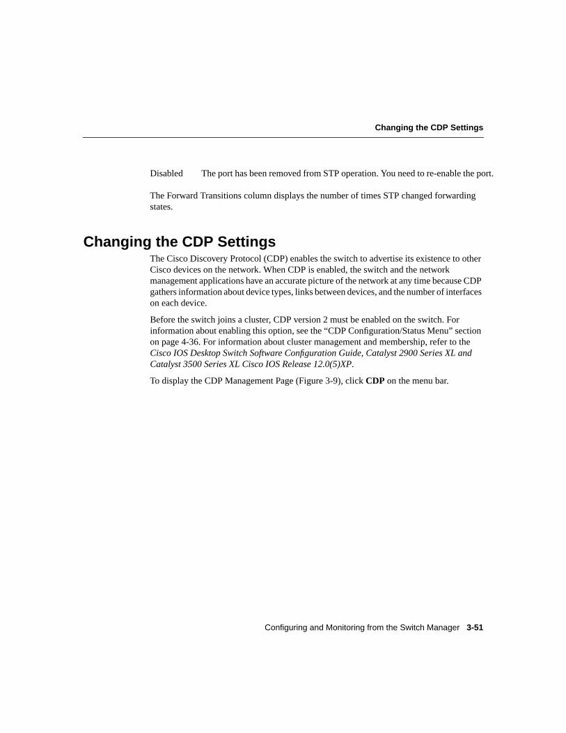
Changing the CDP SettingsThe Cisco Discovery Protocol (CDP) enables the switch to advertise its existence to otherCisco devices on the network. When CDP is enabled, the switch and the networkmanagement applications have an accurate picture of the network at any time because CDPgathers information about device types, links between devices, and the number of interfaceson each device.
Before the switch joins a cluster, CDP version 2 must be enabled on the switch. Forinformation about enabling this option, see the “CDP Configuration/Status Menu” sectionon page 4-36. For information about cluster management and membership, refer to theCisco IOS Desktop Switch Software Configuration Guide, Catalyst 2900 Series XL andCatalyst 3500 Series XL Cisco IOS Release 12.0(5)XP.
To display the CDP Management Page (Figure 3-9), clickCDP on the menu bar.
Disabled The port has been removed from STP operation. You need to re-enable the port.
Changing the CDP Settings
Catalyst 1900 Series Installation and Configuration Guide3-52
Figure 3-9 CDP Management Page
2658
4
Select the ports to participatein exchanging CDP information
with other Cisco devices.
10.1.126.35
180
10.1.126.35
HOME PORT ADDRESS CGMPSNMP STP CDP SPAN CONSOLE STATISTICS SYSTEM
Accesses the web console of aconnected neighboring device.
Opens a Telnet session and logs youinto a connected neighboring device.
Displays detailed information about aconnected neighboring device.
Length of time a neighboring device retains CDP information it received from this switch. The packet hold time should be higher than the packet transmission time.
Length of time between transmissions of CDP messages. The packet transmission time should be lower than the packet hold time.
Configuring and Monitoring from the Switch Manager 3-53
Displaying CDP Neighbors
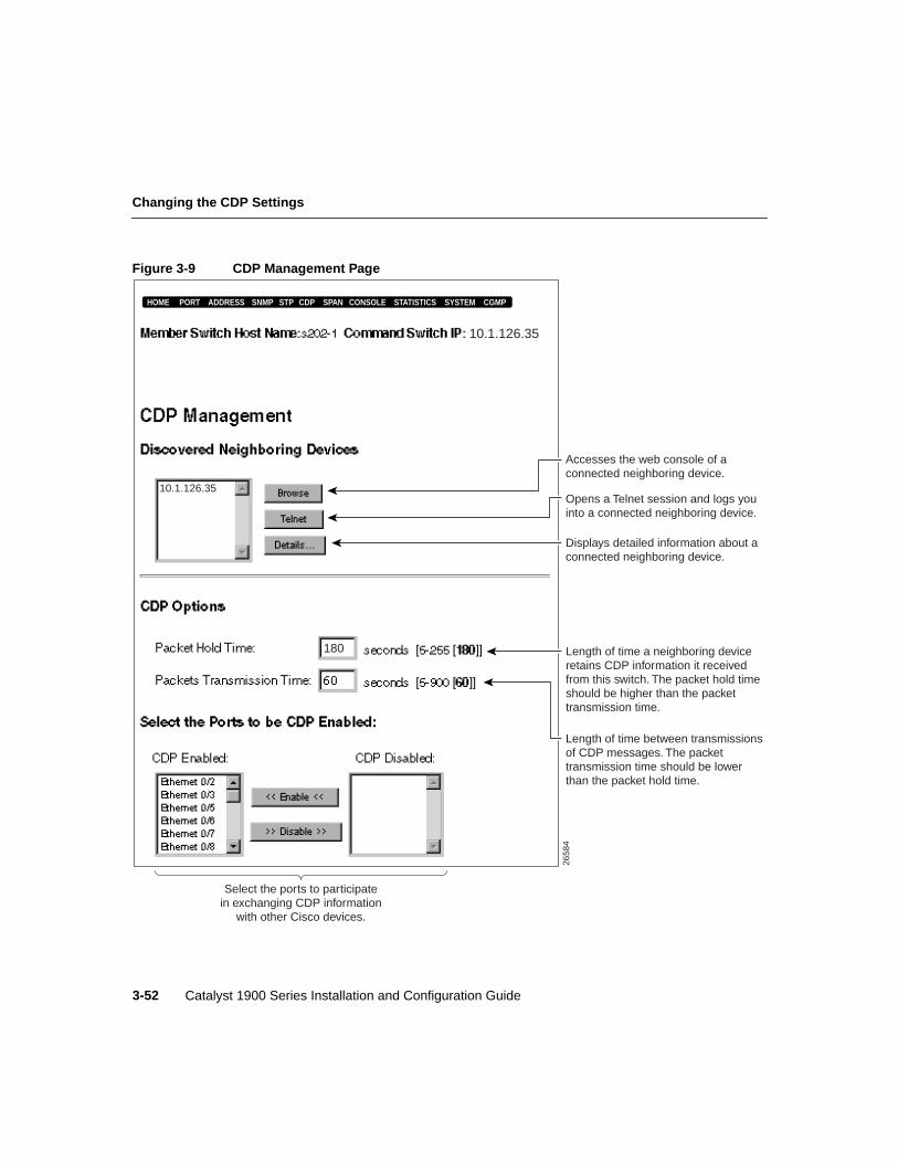
Displaying CDP NeighborsThe Discovered Neighboring Devices list shows the devices with which the switchexchanges CDP messages. To display information about neighboring devices:
Step 1 Select a device from the Discovered Neighboring Devices list.
Step 2 Click one of these buttons:
• Click Browse to access the web console of a neighboring device. Theneighbor must be a device that has web-console support.
• Click Telnet to open a Telnet session and log into a neighboring device.
• Click Details to display the detailed CDP information currently stored in theswitch.
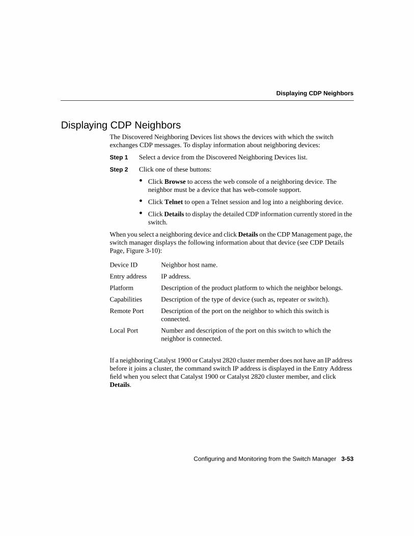
When you select a neighboring device and clickDetailson the CDP Management page, theswitch manager displays the following information about that device (see CDP DetailsPage, Figure 3-10):
If a neighboring Catalyst 1900 or Catalyst 2820 cluster member does not have an IP addressbefore it joins a cluster, the command switch IP address is displayed in the Entry Addressfield when you select that Catalyst 1900 or Catalyst 2820 cluster member, and clickDetails.
Device ID Neighbor host name.
Entry address IP address.
Platform Description of the product platform to which the neighbor belongs.
Capabilities Description of the type of device (such as, repeater or switch).
Remote Port Description of the port on the neighbor to which this switch isconnected.
Local Port Number and description of the port on this switch to which theneighbor is connected.
Changing the CDP Settings
Catalyst 1900 Series Installation and Configuration Guide3-54
Figure 3-10 CDP Details Page
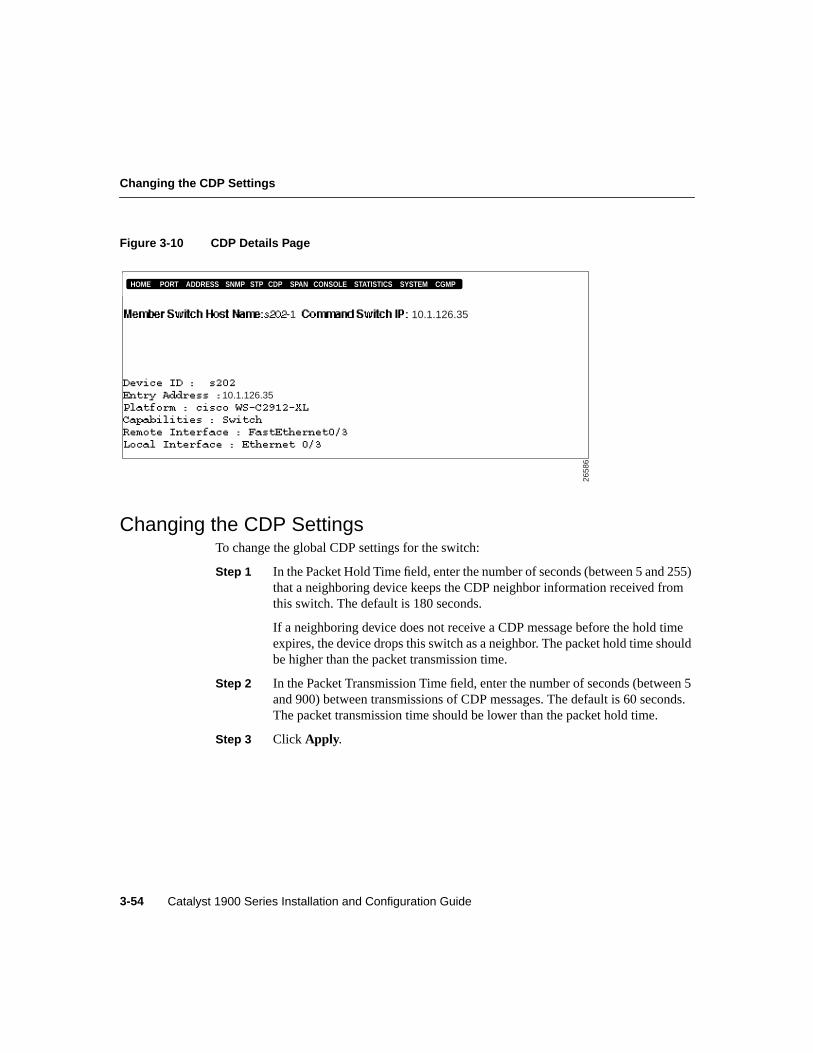
Changing the CDP SettingsTo change the global CDP settings for the switch:
Step 1 In the Packet Hold Time field, enter the number of seconds (between 5 and 255)that a neighboring device keeps the CDP neighbor information received fromthis switch. The default is 180 seconds.
If a neighboring device does not receive a CDP message before the hold timeexpires, the device drops this switch as a neighbor. The packet hold time shouldbe higher than the packet transmission time.
Step 2 In the Packet Transmission Time field, enter the number of seconds (between 5and 900) between transmissions of CDP messages. The default is 60 seconds.The packet transmission time should be lower than the packet hold time.
Step 3 Click Apply.
2658
6
10.1.126.35
HOME PORT ADDRESS CGMPSNMP STP CDP SPAN CONSOLE STATISTICS SYSTEM
10.1.126.35
1
Configuring and Monitoring from the Switch Manager 3-55
Enabling or Disabling CDP on a Port
Enabling or Disabling CDP on a PortBy default, CDP is enabled on all ports on the switch. If you do not want a port to exchangeinformation with Cisco devices, you can disable CDP on that port. To disable CDP on aport:
Step 1 Select the port from the CDP Enabled list.
Step 2 Click Disable.
Note Only 15 ports can be selected at a time. Repeat these steps until you have removedthe ports that you no longer want to participate in CDP exchanges.
To enable CDP on a port:
Step 1 Select the port from the CDP Disabled list.
Step 2 Click Enable.
Note Only 15 ports can be selected at a time. Repeat these steps until you have added theports that you want to participate in CDP exchanges.
Port Monitoring (Switched Port Analyzer)
Catalyst 1900 Series Installation and Configuration Guide3-56
Port Monitoring (Switched Port Analyzer)The remote monitoring (RMON) capability on the switch helps you monitor network traffictraversing the switch, and with the Switched Port Analyzer (SPAN) feature, you can use asingle network analyzer to monitor traffic on any of the switch ports. You simply attach thenetwork analyzer to a switch port, using that port as a monitoring port. You can also use anetwork analyzer on the monitoring port to troubleshoot network problems by examiningthe traffic on other Cisco switched ports or segments.
By default, no port on the switch is designated as the monitoring port, and no ports on theswitch are monitored. Remember the following restrictions when monitoring ports:
• The monitoring port cannot be a member of more than one bridge group.
• Do not make bridge group membership changes on the monitoring port or monitoredports until after you disable monitoring.
Note STP and BOOTP are disabled on the enabled monitor port. The flooding ofunregistered multicast packets and unknown unicast packets is also disabled.
Note Enable monitoring only for problem diagnosis. Disable monitoring during normaloperation so that switch performance is not degraded.
To display the SPAN Configuration Page (Figure 3-11), clickSPAN on the menu bar.
Configuring and Monitoring from the Switch Manager 3-57
Port Monitoring (Switched Port Analyzer)
Figure 3-11 SPAN Configuration Page
Select the portsto be monitored.
Ethernet 0/1
10.1.126.35
Ethernet 0/2Ethernet 0/3Ethernet 0/4Ethernet 0/5Ethernet 0/6
HOME PORT ADDRESS CGMPSNMP STP CDP SPAN CONSOLE STATISTICS SYSTEM
2658
8
Set the switch to monitor ornot monitor traffic on theselected monitored ports.
Select the monitoring port(the port to which capturedframes are sent).
Port Monitoring (Switched Port Analyzer)
Catalyst 1900 Series Installation and Configuration Guide3-58
By default, port monitoring is disabled (Capturing Frames to the Monitoring Port checkbox is not selected).
To enable port monitoring on the switch and its port(s):
Step 1 Select theCapturing Frames to the Monitoring Port check box.
Step 2 Select the monitoring port (the port to which captured frames are sent) from theSelect Monitoring Port drop-down list.
You can designate any port as the monitoring port, but the following restrictionsapply:
• The monitoring port cannot be a member of more than one bridge group.
• Do not make bridge group membership changes on the monitoring port ormonitored ports until after you disable monitoring.
Step 3 Select the port(s) you want to monitor from the Port Not Monitored list.
Step 4 Click Add.
Note Only 15 ports can be selected at a time. Repeat these steps until you haveadded all of the ports that you want to monitor.
To disable port monitoring on a port or ports:
Step 1 Select the port(s) that you no longer want to monitor from the Ports Monitoredlist.
Step 2 Click Remove.
Note Only 15 ports can be selected at a time. Repeat these steps until you haveremoved all of the ports that you no longer want to monitor.
Configuring and Monitoring from the Switch Manager 3-59
Changing the Console Port Settings and Upgrading the Firmware
Changing the Console Port Settings and Upgrading theFirmware
Cisco periodically provides new firmware to implement enhancements and maintenancereleases. New firmware releases can be downloaded from Cisco Connection Online (CCO),the Cisco Systems’ customer web site available at the following URLs: www.cisco.com,www-china.cisco.com, and www-europe.cisco.com.
The Firmware Version field displays the firmware version being used by the switch.
Caution If you interrupt the transfer by turning the switch off and on, thefirmware could get corrupted. For recovery procedures, see the “Recovering fromCorrupted Firmware” section on page 5-13.
Note When you download the firmware to Flash memory, the switch does not respond tocommands for approximately 1 minute. This is normal and correct. Unlike the managementconsole, the switch manager does not provide any status on the download. Do not turn offthe switch until after the switch resets and begins using the new firmware.
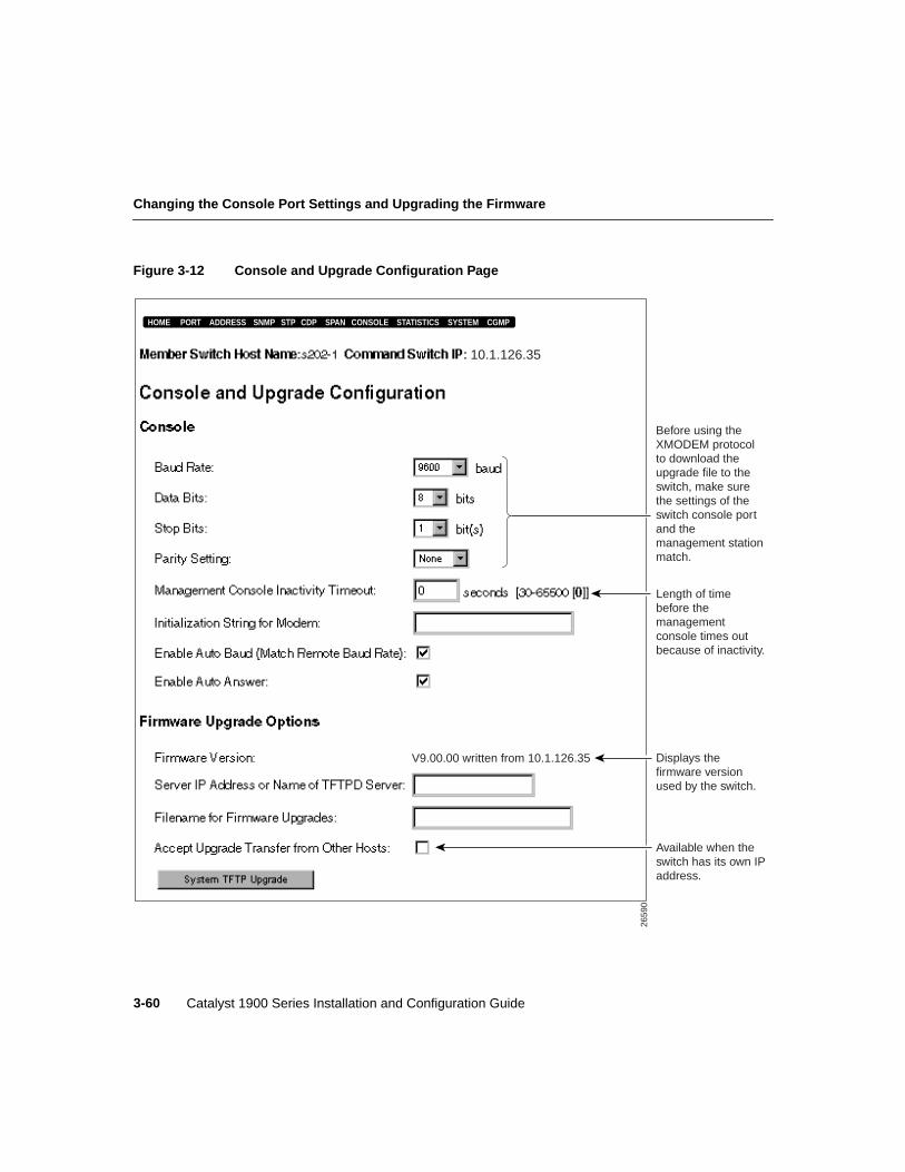
To display the Console and Upgrade Configuration Page (Figure 3-12), clickConsole onthe menu bar.
Changing the Console Port Settings and Upgrading the Firmware
Catalyst 1900 Series Installation and Configuration Guide3-60
Figure 3-12 Console and Upgrade Configuration Page
2659
0
V9.00.00 written from 10.1.126.35
10.1.126.35
HOME PORT ADDRESS CGMPSNMP STP CDP SPAN CONSOLE STATISTICS SYSTEM
Before using the XMODEM protocol to download the upgrade file to the switch, make sure the settings of the switch console port and the management station match.
Length of time before the management console times out because of inactivity.
Displays the firmware version used by the switch.
Available when the switch has its own IP address.
Configuring and Monitoring from the Switch Manager 3-61
Configuring the Switch Console Port
Configuring the Switch Console PortThe console port on the switch provides terminal and PC access to the switch. After theswitch is installed, be sure to configure the console port settings of the switch to match thesettings of the terminal or PC.
These are the default settings of the switch console port:
• Baud rate default is 9600.
• Data bits default is 8.
Note If the data bits option is set to 8, set the parity option to None.
• Stop bits default is 1.
• Parity settings default is None.
If you change any of these settings, clickApply to save your changes.
Management Console Inactivity TimeoutBy default, the management console inactivity timeout is 0 (which means the consolesession does not time out). You can change the number of seconds that the managementconsole can wait without activity before it times out. After timeout, you must reenter thepassword.
To change the inactivity timeout setting:
Step 1 Enter the number of seconds (0, or 30 to 65500) in the Management ConsoleInactivity Timeout field.
Step 2 Click Apply.
Changing the Console Port Settings and Upgrading the Firmware
Catalyst 1900 Series Installation and Configuration Guide3-62
Modem Initialization StringThe switch uses the initialization string to initialize the modem connected to the consoleport. This string must match your modem requirement.
Note Do not use an AT prefix or end-of-line suffix.
Auto BaudBy default, auto baud (match remote baud rate) is enabled (Enable Auto Baudcheck boxis selected). This option enables the switch to automatically match the same or lower baudrate of an incoming call. After the call, the switch reverts to its configured rate.
Auto AnswerBy default, auto answer is enabled (Enable Auto Answer check box is selected). Thisoption enables the switch to automatically answer calls.
Upgrading the Switch FirmwareThe Firmware Version field displays the firmware version being used by the switch.
The following sections provide instructions on how to upgrade the switch firmware:
• “Downloading Switch Firmware from a TFTP Server” section on page 3-63
• “Downloading Switch Firmware from a TFTP Client” section on page 3-64
Configuring and Monitoring from the Switch Manager 3-63
Upgrading the Switch Firmware
Downloading Switch Firmware from a TFTP Server
Caution If you interrupt the transfer by turning the switch off and on, the firmware couldget corrupted. For recovery procedures, see the “Recovering from Corrupted Firmware”section on page 5-13.
Follow these steps to download the latest firmware from a TFTP server to your switch.
Step 1 Download the upgrade file from CCO into an appropriate directory on yourTFTP server.
Step 2 Enter the IP address in the Server: IP Address or Name of TFTP Server field.Use dotted quad format (nnn.nnn.nnn.nnn).
If the switch is connected to a Domain Name System (DNS) server, you canenter the name of the TFTP server instead.
Step 3 Enter the upgrade filename (up to 80 characters) in the Filename for FirmwareUpgrades field.
Step 4 Click System TFTP Upgrade to download the upgrade file from the TFTPserver to the switch.
Step 5 Click OK on the confirmation prompt.
Note When you download the firmware to Flash memory, the switch does notrespond to commands for approximately 1 minute. This is normal and correct.Unlike the management console, the switch manager does not provide any statuson the download. Do not turn off the switch until after the switch resets andbegins using the new firmware.
After the existing firmware validates the file, the new image is transferred intoFlash memory, the switch resets, and the new firmware begins executing. If theupgrade file is invalid, the temporary image is discarded, the existing firmwarecontinues to execute, and the firmware upgrade ends.
Step 6 Click the browserReload button to refresh the Console and UpgradeConfiguration Page.
Step 7 Ensure that the Firmware Version field displays the updated firmware version.
Changing the Console Port Settings and Upgrading the Firmware
Catalyst 1900 Series Installation and Configuration Guide3-64
Downloading Switch Firmware from a TFTP Client
Caution If you interrupt the transfer by turning the switch off and on, the firmware couldget corrupted. For recovery procedures, see the “Recovering from Corrupted Firmware”section on page 5-13.
Follow these steps to download the latest firmware from a TFTP client to your switch.
Step 1 Download the upgrade file from CCO into an appropriate directory on yourTFTP client.
Step 2 From the client management station, establish a TFTP session with the IPaddress of the switch. Make sure the client station is in binary transfer mode.
Step 3 Select theAccept Upgrade Transfer from Other Hostscheck box. By default,this check box is not selected.
Note To prevent unauthorized upgrades, deselect this check box after youupgrade the firmware.
Step 4 Download the upgrade file from the client station to the switch, using the TFTPuser interface or the appropriate command for the put operation (such as,putupgrade_ filename).
Note When you download the firmware to Flash memory, the switch does notrespond to commands for approximately 1 minute. This is normal and correct.Unlike the management console, the switch manager does not provide any statuson the download. Do not turn off the switch until after the switch resets andbegins using the new firmware.
After the existing firmware validates the file, the new image is transferred intoFlash memory, the switch resets, and the new firmware begins executing. If theupgrade file is invalid, the temporary image is discarded, the existing firmwarecontinues to execute, and the firmware upgrade ends.
Configuring and Monitoring from the Switch Manager 3-65
Exception and Utilization Statistics
Step 5 Click the browserReload button to refresh the Console and UpgradeConfiguration Page.
Step 6 Ensure that the Firmware Version field displays the updated firmware version.
Step 7 Deselect theAccept Upgrade Transfer from Other Hosts check box.
Exception and Utilization StatisticsThe Statistics Reports Page (Figure 3-13) displays the exception and utilization statisticsfor the switch. To display this page, clickStatisticson the menu bar.
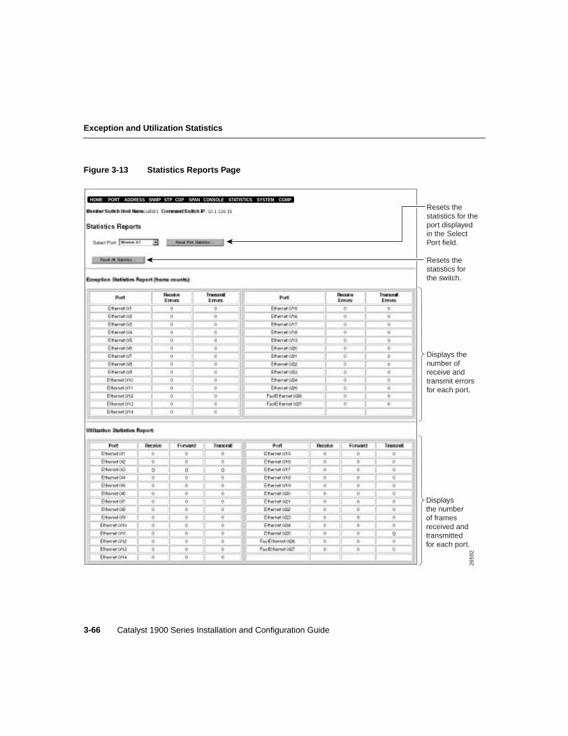
Exception and Utilization Statistics
Catalyst 1900 Series Installation and Configuration Guide3-66
Figure 3-13 Statistics Reports Page
2659
2
Displays thenumber ofreceive andtransmit errorsfor each port.
Displaysthe numberof framesreceived andtransmittedfor each port.
0
HOME PORT ADDRESS CGMPSNMP STP CDP SPAN CONSOLE STATISTICS SYSTEM
000
Resets thestatistics for theport displayedin the SelectPort field.
Resets thestatistics forthe switch.
10.1.126.351
Configuring and Monitoring from the Switch Manager 3-67
Resetting Port and Switch Statistics
Resetting Port and Switch StatisticsTo reset the statistics for a switch port:
Step 1 Select the port from the Select Port list.
Step 2 Click Reset Port Statistics.
To reset the statistics for all ports on the switch, clickReset All Statistics.
The switch manager does not automatically refresh the statistics shown on this page. Clickthe browserReload button to refresh the statistics shown on this page.
Exception StatisticsThis report displays the number of receive and transmit errors for each port.
Utilization StatisticsThis report displays the number of bytes received and transmitted for each port.
Receive Number of giants and FCS and alignment errors
Transmit Number of excessive deferrals, late collisions, jabber errors, and othertransmit errors
Receive Number of bytes received in good packets
Forward Number of good frames forwarded
Transmit Number of bytes transmitted
Changing the System Management Settings
Catalyst 1900 Series Installation and Configuration Guide3-68
Changing the System Management SettingsThe system management settings include the switch IP information and the settings forswitch performance and flood and traffic control. To display the System Management Page(Figure 3-14), clickSystem on the menu bar.
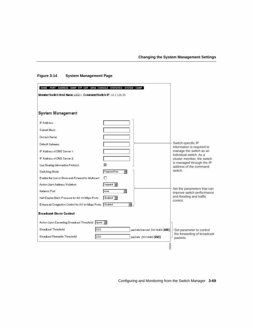
Configuring and Monitoring from the Switch Manager 3-69
Changing the System Management Settings
Figure 3-14 System Management Page
2659
4
Switch-specific IP information is required to manage the switch as an individual switch. As a cluster member, the switch is managed through the IP address of the command switch.
Set the parameters that can improve switch performance and flooding and traffic control.
Set parameter to control the forwarding of broadcast packets.
10.1.126.35
HOME PORT ADDRESS CGMPSNMP STP CDP SPAN CONSOLE STATISTICS SYSTEM
1
Changing the System Management Settings
Catalyst 1900 Series Installation and Configuration Guide3-70
Assigning or Changing IP InformationTypically, after the switch is installed, an IP address is assigned to the switch. (See the“Assigning IP Information and a Password to the Switch” section on page 2-19.)
IP information identifies the switch on the network and is required to configure and monitorit as an individual switch. When you assign the switch its own IP address, you can manageit from its management interfaces (switch manager, management console, SNMP, or CLI).The switch retains its own IP address even when it joins or leaves a switch cluster.
If you do not assign an IP address to the switch, you must add the switch to a switch clusterand manage it through the command switch. Whether or not the switch has its own IPaddress, when the switch is a cluster member, it is managed and communicates with othermember switches through the IP address of the command switch. If the switch leaves thecluster and it does not have its own IP address, you then must assign IP information to it tomanage and monitor it as a nonmember switch.
Note We recommend that you assign an IP address to the switch even if the switch is orwill be a cluster member so that if the switch is removed from the cluster, it remainsmanageable as a nonmember switch.
Note You access the switch manager from a management station that is connected to oneof the switch ports. Therefore, make sure that you do not disable or otherwise misconfigurethe port through which you are communicating with the switch. You might want to writedown the port number to which you are connected. Make changes to the switch IPinformation with care.
For information about IP information in switch clusters, refer to theCisco IOS DesktopSwitch Software Configuration Guide, Catalyst 2900 Series XL and Catalyst 3500 SeriesXL Cisco IOS Release 12.0(5)XP.
Configuring and Monitoring from the Switch Manager 3-71
Assigning or Changing IP Information
To change the switch IP information:
Step 1 Enter a new IP address for the switch in the IP Address field. Use dotted quadformat (nnn.nnn.nnn.nnn).
If the switch is connected to a network that has a Dynamic Host ConfigurationProtocol (DHCP)/Bootstrap Protocol (BOOTP) server, the server automaticallyassigns it an IP address.
This field displays the IP address assigned to the switch. If the switch does nothave an IP address, this field displays 0.0.0.0.
Caution Changing the switch IP address on this page will end your switch managersession. You will need to open a new session and enter the new IP address in the URL fieldif you are using Communicator (the Address field if you are using Internet Explorer).
Note We recommend that you assign an IP address to the switch even if the switch is orwill be a cluster member so that if the switch is removed from the cluster, it remainsmanageable as a nonmember switch.
Step 2 Enter the subnet mask for the switch in the Subnet Mask field.
Subnet masks exist only if the network has been divided up into subnetworks.
Step 3 In the Domain Name field, enter the domain name (up to 62 characters) of theDomain Name System (DNS) server to which the switch is associated (such ascisco.com).
Step 4 In the Default Gateway field, enter the IP address of the default gateway. Usedotted quad format (nnn.nnn.nnn.nnn).
The default gateway is the router that the switch uses to reach IP subnets otherthan the local subnet to which the switch is attached. A default gateway is alsonecessary if the management station from which the switch is to be managed isnot on the same IP subnet as the switch.
For automatic IP gateway assignment, see the “Routing Information Protocol”section on page 3-72.
Changing the System Management Settings
Catalyst 1900 Series Installation and Configuration Guide3-72
Step 5 In the IP Address of DNS Server 1 and 2 fields, enter the IP address(es) of theDNS server(s). For more information about the DNS server, see the “DomainName System Servers” section on page 3-72.
Step 6 Click Apply.
Domain Name System ServersA network device can be identified through its IP address or its associated host name.Domain Name System (DNS) servers maintain name-to-address mappings.
If you enter the device name when using the switch management interfaces, the DNS serverassociated with the switch looks up the device IP address. The switch can be associated toup to two DNS servers.
To associate a DNS server to the switch:
Step 1 Enter the IP address of the DNS server in the IP Address of DNS Server field.Use dotted quad format (nnn.nnn.nnn.nnn).
Step 2 Click Apply.
Routing Information ProtocolBy default, the Routing Information Protocol (RIP) is enabled (Use Routing InformationProtocol check box is selected). RIP automatically discovers and assigns an IP gateway tothe switch.
The default gateway is the router that the switch uses to reach IP subnets other than the localsubnet to which the switch is attached. A default gateway is also necessary if themanagement station from which the switch is to be managed is not on the same IP subnetas the switch.
Configuring and Monitoring from the Switch Manager 3-73
Switch Performance and Flooding and Traffic Control
Switch Performance and Flooding and Traffic Control
Switching ModesBy default, the switching mode is FragmentFree (cut-through). The switching modedetermines how quickly the switch forwards a packet and, therefore, how much latency thepacket experiences.Latencyis the delay between the time a port begins to receive a packetand the time the port begins to transmit the packet to a destination port. FragmentFree modefilters out collision fragments before forwarding. Store-and-forward stores completepackets and checks for errors before forwarding.
The switch uses these switching modes:
• FragmentFree—This mode iscut-through switching. The FragmentFree mode filtersout collision fragments (the majority of packet errors) before forwarding begins. In aproperly functioning network, collision fragments are packets with less than 64 bytes.In FragmentFree mode, the switch waits until 64 bytes are received (determines thereceived packet is not a collision fragment) before forwarding the packet. InFragmentFree mode, latency is measured as first-bit-received to first-bit-transmitted or“First-In, First-Out” (FIFO).
If latency is an issue, use FragmentFree switching.
• Store-and-forward—This mode stores complete packets and checks for errors beforetransmission. In this mode, latency is measured as last-bit-received tofirst-bit-transmitted or “Last-In, First-Out” (LIFO). This latency does not include thetime to receive the entire packet, which can vary according to packet size. At 10 Mbps,the packet receipt time varies between 51.2 microseconds and 1.2 milliseconds. At100 Mbps, the packet receipt time varies between 5.12 and 122 microseconds. Thestore-and-forward mode is always used for broadcast packets and transfers from10-Mbps to 100-Mbps ports.
Store-and-forward is the most error-free form of switching, but the forwarding latencyis higher than FragmentFree (cut-through) switching. If you have frame check sequence(FCS) or alignment errors, use the store-and-forward mode so that packets with errorsare filtered and not propagated to the rest of the network.
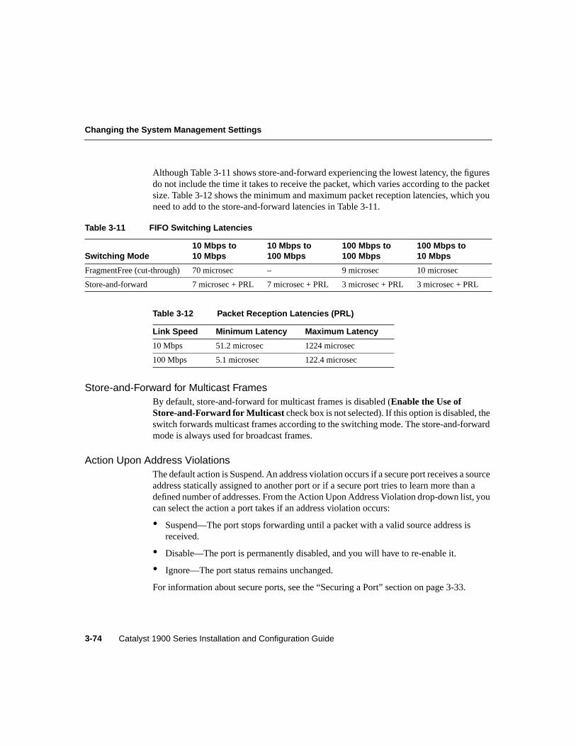
Changing the System Management Settings
Catalyst 1900 Series Installation and Configuration Guide3-74
Although Table 3-11 shows store-and-forward experiencing the lowest latency, the figuresdo not include the time it takes to receive the packet, which varies according to the packetsize. Table 3-12 shows the minimum and maximum packet reception latencies, which youneed to add to the store-and-forward latencies in Table 3-11.
Store-and-Forward for Multicast FramesBy default, store-and-forward for multicast frames is disabled (Enable the Use ofStore-and-Forward for Multicast check box is not selected). If this option is disabled, theswitch forwards multicast frames according to the switching mode. The store-and-forwardmode is always used for broadcast frames.
Action Upon Address ViolationsThe default action is Suspend. An address violation occurs if a secure port receives a sourceaddress statically assigned to another port or if a secure port tries to learn more than adefined number of addresses. From the Action Upon Address Violation drop-down list, youcan select the action a port takes if an address violation occurs:
• Suspend—The port stops forwarding until a packet with a valid source address isreceived.
• Disable—The port is permanently disabled, and you will have to re-enable it.
• Ignore—The port status remains unchanged.
For information about secure ports, see the “Securing a Port” section on page 3-33.
Table 3-11 FIFO Switching Latencies
Switching Mode10 Mbps to10 Mbps
10 Mbps to100 Mbps
100 Mbps to100 Mbps
100 Mbps to10 Mbps
FragmentFree (cut-through) 70 microsec – 9 microsec 10 microsec
Store-and-forward 7 microsec + PRL 7 microsec + PRL 3 microsec + PRL 3 microsec + PRL
Table 3-12 Packet Reception Latencies (PRL)
Link Speed Minimum Latency Maximum Latency
10 Mbps 51.2 microsec 1224 microsec
100 Mbps 5.1 microsec 122.4 microsec
Configuring and Monitoring from the Switch Manager 3-75
Switch Performance and Flooding and Traffic Control
Network PortA unicast address identifies one unique device on the network. However, if the switch hasnot received packets from the device for a while (longer than the aging period), the switchremoves the device address from its address table, and the address is then an unknownunicast address. The switch must flood (send to all ports except the one the packet isreceived on) packets destined for the unknown unicast address in order to ensure the devicereceives the packet. Once the switch learns the location of the device, this flooding stops.
The use of a network port can eliminate this type of flooding. The network port that youselect from the Network Port drop-down list is the destination port for all packets withunknown unicast addresses. By default, no port is assigned as the network port.
The network port
• Does not learn addresses.
• Serves only within the bridge groups of which the Network Port is member.
• Is usually connected to a legacy network or backbone.
• Cannot be a secure port.
• Cannot be port A or B if the following enterprise edition software features are enabled:Fast EtherChannel mode or VLAN or ISL trunking.
For more information about unicast addresses, see the “Enabling or Disabling Flooding ofUnknown MAC Addresses” section on page 3-21 and the “Permanent Unicast AddressTable” section on page 3-29.
Half-Duplex Back Pressure on 10-Mbps PortsBy default, half-duplex back pressure on all 10-Mbps ports is disabled. Back pressureensures retransmission of incoming packets if a half-duplex 10-Mbps switch port is unableto receive incoming packets.
When back pressure is enabled and no buffers are available to a port, the switch generatescollision frames across the affected port and causes the transmitting station to resend thepackets. The switch can then use this retransmission time to clear its receive buffer bytransmitting packets already in the queue.
For information about flow control on the 100-Mbps ports, see the “Flow Control” sectionon page 3-20.
Changing the System Management Settings
Catalyst 1900 Series Installation and Configuration Guide3-76
ECC on 10-Mbps PortsBy default, enhanced congestion control (ECC) is disabled on all 10-Mbps ports. AnECC-enabled port accelerates transmission of frames and empties its queue more quickly.This option reduces congestion on the switch and keeps the switch from dropping framesbecause of full transmit queues. The ECC option can be enabled on half-duplex ports andcan be configured on a global basis for the 10-Mbps ports.
For information about ECC on the 100-Mbps ports, see the “Enabling or Disabling ECC onthe 100-Mbps Ports” section on page 3-22. ECC on the 100-Mbps ports is set on a per-portbasis, not on a global basis.
To enable ECC on a 10-Mbps port:
Step 1 Select one of the following modes from the Enhanced Congestion Controldrop-down list.
• Adaptive—Causes the port to operate under the ECC Disabled setting if thetransmit queue is not full. If the queue is full, the port uses the ECCAggressive setting.
• Disabled—Causes the port to operate under the standard IEEE 802.3 backoffalgorithm for retransmitting frames.
• Moderately Aggressive—Causes the port to use a modified backoffalgorithm to more aggressively retransmit frames and empty the queue.
• Aggressive—Is the highest acceleration rate configurable for ECC. The portuses a modified backoff algorithm to more aggressively retransmit framesand empty the queue than when set at ECC Moderately Aggressive.
Step 2 Click Apply.
Broadcast Storm ControlA broadcast storm is an excessive number of broadcast packets being received on a givenswitch port. Broadcast storm packets can congest the receiving switch port. If the switchport forwards a broadcast storm to the other switch ports, traffic on those ports and allnetwork segments are also affected. You can use broadcast storm control to control thequantity of broadcast packets the switch forwards to your network, thus reserving switchbandwidth for your network users.
Configuring and Monitoring from the Switch Manager 3-77
Switch Performance and Flooding and Traffic Control
Use the broadcast storm control settings to inhibit the forwarding of broadcast packetswhen the broadcast rate (number of broadcast packets received from a port per second) ona switch port exceeds a specified threshold. Broadcast storm control is configured for theswitch as a whole, but operates on a per-port basis.
Note Only broadcast packets are filtered through the broadcast storm control option. Forinformation about unicast and multicast flooding control, see the “Enabling or DisablingFlooding of Unknown MAC Addresses” section on page 3-21 and the “Managing MulticastPackets with CGMP” section on page 3-78.
To change the broadcast storm control settings:
Step 1 SelectBlock or Ignore in the Action Upon Exceeding Broadcast Thresholdfield. The default is Ignore.
This option assigns the action the switch takes if the number of broadcastpackets reaches the broadcast threshold:
• Block—The switch drops all broadcast packets received from a port if thebroadcast threshold is exceeded. The switch resumes forwarding if the rateof broadcast packets received drops below the re-enable threshold.
• Ignore—The switch forwards broadcast packets. There is no set threshold.
Step 2 In the Broadcast Threshold field, enter the threshold that constitutes a broadcaststorm. The range is 10 to 14400 broadcast packets received from a port persecond. The default is 500.
When this threshold is exceeded, the switch, if configured to do so, blocks thebroadcast packets received from the port and generates an SNMP alert.
Step 3 In the Broadcast Reenabled Threshold field, enter the threshold below whichbroadcast forwarding is re-enabled. The range is 10 to 14400 packets. Thedefault is 250.
Step 4 Click Apply.
Managing Multicast Packets with CGMP
Catalyst 1900 Series Installation and Configuration Guide3-78
Managing Multicast Packets with CGMPA multicast packet is information sent to multiple recipients from one sender. However,sometimes multicast traffic needs to be received only on certain networks segments, and notall. Indiscriminant flooding of multicast traffic can waste bandwidth on the switch andcongest each segment.
The Cisco Group Management Protocol (CGMP) dynamically creates CGMP groups,which are designated recipients of multicast traffic. This limits the transmission ofmulticast packets to only end-stations that request them, thereby reducing flooding ofmulticast traffic within the network.
IP multicast routers are required to forward multicast packets across an IP internetwork.CGMP filtering requires a network connection from a CGMP-enabled switch to a routerrunning CGMP. End stations issue join messages to become part of a CGMP group andissue leave messages to leave the group. A CGMP-enabled router sends CGMP packets toinform the switch when specific end-stations join or leave a CGMP group. When CGMP isenabled on the switch, the switch ports forward multicast traffic only to CGMP groupmembers.
A CGMP group remains in the switch IP Multicast Address Table until all members haveleft that group. The switch supports up to 64 IP multicast group registrations. Forinformation about multicast registrations, see the “Permanent Multicast Address Table”section on page 3-30.
To display the CGMP Management Page (Figure 3-15), clickCGMP on the menu bar.
For additional information, see the
• “Permanent Multicast Address Table” section on page 3-30
• “Changing the System Management Settings” section on page 3-68
• “Store-and-Forward for Multicast Frames” section on page 3-74
For information about IP multicast, including Internet Group Management Protocol(IGMP), refer to RFC 1112.
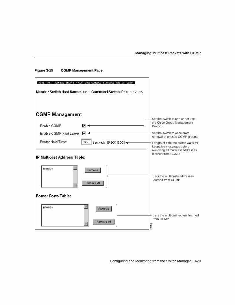
Configuring and Monitoring from the Switch Manager 3-79
Managing Multicast Packets with CGMP
Figure 3-15 CGMP Management Page
2659
6
(none)
(none)
10.1.126.351
HOME PORT ADDRESS CGMPSNMP STP CDP SPAN CONSOLE STATISTICS SYSTEM
Set the switch to use or not usethe Cisco Group ManagementProtocol.
Set the switch to accelerateremoval of unused CGMP groups.
Lists the multicasts addresseslearned from CGMP.
Lists the multicast routers learnedfrom CGMP.
600 600 Length of time the switch waits forkeepalive messages beforeremoving all multicast addresses learned from CGMP.
Managing Multicast Packets with CGMP
Catalyst 1900 Series Installation and Configuration Guide3-80
Changing the CGMP SettingsBy default, CGMP is enabled (Enable CGMP check box is selected) on the switch.
To disable CGMP:
Step 1 Deselect the Enable CGMP check box.
Step 2 Click Apply.
CGMP Fast LeaveThe CGMP Fast Leave option can eliminate unnecessary multicast traffic to switch portsthat no longer have group members needing that specific multicast traffic. By default, theCGMP Fast Leave option is disabled (Enable CGMP Fast Leave check box is notselected).
Note For CGMP Fast Leave to take effect, all CGMP group members must have IGMPversion 2 enabled.
When this option is enabled, the following rules are in effect:
• If there are no CGMP group members associated with a switch port, the switchdisassociates that port from the CGMP group.
• If a CGMP group has no members on any switch port, the CGMP group is removed fromthe switch IP Multicast Address Table.
To enable CGMP Fast Leave:
Step 1 Select theEnable CGMP Fast Leave check box.
Step 2 Click Apply.
Configuring and Monitoring from the Switch Manager 3-81
IP Multicast Address Table
Router Hold TimeThe Router Hold Time field displays the number of seconds (between 5 and 900) that theswitch waits for keepalive messages before deleting CGMP-learned multicast groups. Bydefault, the router hold time is 600.
Multicast routers that support CGMP periodically send CGMP join messages to advertisethemselves to switches within a network. A receiving switch saves the information and setsa timer equal to the router hold time. The timer is updated every time the switch receives aCGMP join message advertising itself. When the last router hold time expires, the switchremoves all IP multicast groups learned from CGMP.
To change the router hold time:
Step 1 In the Router Hold Time field, specify the number of seconds (5 to 900) theswitch waits before removing all IP multicast groups learned from CGMP.
Step 2 Click Apply.
IP Multicast Address TableWhen CGMP is enabled on the switch, the switch automatically creates and dynamicallymaintains a table that lists the addresses of designated multicast recipients and theassociated switch port(s) through which multicast traffic are forwarded to those recipients.
If you have configured bridge groups, the bridge group number is not displayed on the IPMulticast Address Table. For more information about bridge groups, see the “Bridge GroupConfiguration Menu” section on page 4-64.
Caution Use theRemoveoption only to debug and recover from unexpected situations.
To delete a specific entry from the IP Multicast Address Table:
Step 1 Select the entry you want to delete.
Step 2 Click Remove.
Click Remove All to clear the table.
Managing Multicast Packets with CGMP
Catalyst 1900 Series Installation and Configuration Guide3-82
Router Ports TableCGMP filtering requires a network connection from the switch to a router running CGMP.When CGMP is enabled on the switch, the switch automatically creates and dynamicallymaintains a table that lists the IP address of each attached CGMP-enabled router and theswitch port to which the router is attached.
To delete a specific entry from the Router Ports Table:
Step 1 Select the entry you want to delete.
Step 2 Click Remove.
Click Remove All to clear the table.