Embed Size (px)
Citation preview

TECHNICAL BRIEF
Overview This document explains the WDS(Wireless Distribution System) features provided by the 3Com®
OfficeConnect® Wireless 11a/b/gAccess Point (3CRWE454A72). Thesefeatures allow you to build a com-pletely wireless infrastructurebecause the network equipment no
longer has to be connected to a wiredLAN. Also, WDS features allow you tocreate large wireless networks by linking several wireless access pointswith WDS links. WDS is normallyused in large, open areas wherepulling wires is cost prohibitive,restricted or physically impossible.
Configuring a Wireless Distribution System (WDS)with the 3Com® OfficeConnect® Wireless 11a/b/g Access Point
Point-to-Point WDS Link
Point-to-Multipoint WDS Link

3COM ® CONFIGURING A WIRELESS DISTR IBUTION SYSTEM TECHNICAL BR IEF
2
Wireless Bridge andWireless Repeater
As shown in Figure 1, WDS can bedeployed in several configurations. Inthis document, we will introduce twobasic WDS configurations: a wirelessbridge and wireless repeater.
Wireless Bridge
The wireless distribution system shown in Figure 2 is often called a“wireless bridge” configuration,because it allows you to connect twoLANs at the link layer. In Figure 2, theaccess point (AP) behaves as a standardbridge that forwards traffic between
WDS links (links that connect to otherAP/wireless bridges) and an Ethernetport. As a standard bridge, the accesspoint learns MAC addresses of up to64 wireless and/or 128 total wiredand wireless network devices, whichare connected to their respectiveEthernet ports to limit the amount ofdata to be forwarded. Only data des-tined for stations which are known toreside on the peer Ethernet link, mul-ticast data or data with unknowndestinations need to be forwarded tothe peer AP via the WDS link.
Repeater WDS Link
Figure 2: Wireless Bridge Configuration
Figure 1: WDS Configurations
802.3 Ethernet frame
802.11 four-address format frame
WDS link

3COM ® CONFIGURING A WIRELESS DISTR IBUTION SYSTEM TECHNICAL BR IEF
3
Figure 3: Wireless Repeater Configuration
If, for example, an 802.3 Ethernetframe is sent from a wired Station 1(Sta1) to Sta3 in Figure 2, frame trans-lations are required while the frameforwards through the WDS linkbetween AP1 and AP2. When AP1receives the 802.3 frame, the frame istranslated to a IEEE 802.11 standardfour-address format frame before it issent to a WDS link. In the four-address format frame, the MACaddress of Sta1, MAC address of AP1,MAC address of AP2 and MACaddress of Sta3 are all included in the
802.11 frame header, and the framedata is same as the original Ethernetframe. Based on information in thisfour-address format frame, AP2 willreconstruct the 802.3 Ethernet framewhen the frame is forwarded toLAN2. If a security algorithm is con-figured on the APs, AP1(AP2) willencrypt(decrypt) this four-addressformat frame before frame forward-ing. From Sta3’s point of view, thebridging function is transparent; i.e.,the received frame is the same as ifSta1 and Sta3 resided on the same LAN.
Wireless Repeater
In Figure 3, AP2 is used to extend therange of the wireless infrastructure byforwarding traffic between associatedwireless stations and another repeateror AP connected to the wired LAN.Note that the local Ethernet traffic isnot forwarded in this mode. Trafficbetween Sta3 and Sta4 is not for-warded across the WDS link, nor istraffic between Sta5 and Sta6. Aswith a wireless bridge mode, APsoperating in wireless repeater modeneed to translate frames into differentframe formats when forwarding
frames between wireless connectionsand WDS links; the 802.11 three-addressframe format is used on wireless linksconnected to wireless stations, whilethe 802.3 four-address frame format isused on WDS links connected toother access points. Encryption/decryption algorithms are also invokedif the AP is configured to be secure.
The OfficeConnect Wireless 11a/b/gAccess Point can function as a wirelessrepeater or wireless bridge if WDSlinks are configured between the con-nected AP pairs appropriately.
802.3 Ethernet frame
802.11 three-address format frame
802.11 four-address format frameWDS link
3COM ® CONFIGURING A WIRELESS DISTR IBUTION SYSTEM TECHNICAL BR IEF
4
Configuring WDS Links on 3Com OfficeConnectWireless 11a/b/gAccess Points
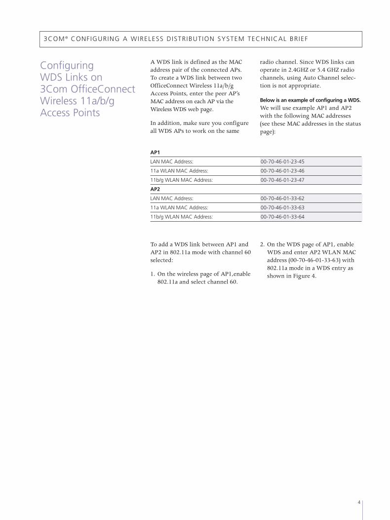
A WDS link is defined as the MACaddress pair of the connected APs. To create a WDS link between twoOfficeConnect Wireless 11a/b/gAccess Points, enter the peer AP’sMAC address on each AP via theWireless WDS web page.
In addition, make sure you configureall WDS APs to work on the same
radio channel. Since WDS links canoperate in 2.4GHZ or 5.4 GHZ radiochannels, using Auto Channel selec-tion is not appropriate.
Below is an example of configuring a WDS.
We will use example AP1 and AP2with the following MAC addresses(see these MAC addresses in the statuspage):
AP1
LAN MAC Address: 00-70-46-01-23-45
11a WLAN MAC Address: 00-70-46-01-23-46
11b/g WLAN MAC Address: 00-70-46-01-23-47
AP2
LAN MAC Address: 00-70-46-01-33-62
11a WLAN MAC Address: 00-70-46-01-33-63
11b/g WLAN MAC Address: 00-70-46-01-33-64
To add a WDS link between AP1 andAP2 in 802.11a mode with channel 60selected:
1. On the wireless page of AP1,enable802.11a and select channel 60.
2. On the WDS page of AP1, enableWDS and enter AP2 WLAN MACaddress (00-70-46-01-33-63) with802.11a mode in a WDS entry asshown in Figure 4.

3. On the wireless page of AP2, enable 802.11a standard and select channel 60.
4. On the WDS page of AP2, enableWDS and enter AP1 WLAN MACaddress (00-70-46-01-23-46) with802.11a mode in a WDS entry asshown in Figure 5.
3COM ® CONFIGURING A WIRELESS DISTR IBUTION SYSTEM TECHNICAL BR IEF
5
Figure 5: Configuring WDSLinks on AP2
Figure 4: Configuring WDSLinks on AP1

3COM ® CONFIGURING A WIRELESS DISTR IBUTION SYSTEM TECHNICAL BR IEF
3Com Corporation, Corporate Headquarters, 350 Campus Drive, Marlborough, MA 01752-3064
To learn more about 3Com solutions, visit www.3com.com. 3Com is publicly traded on NASDAQ under the symbol COMS.
Copyright © 2004 3Com Corporation. All rights reserved. 3Com, the 3Com logo, and OfficeConnect are registered trade-marks of 3Com Corporation. Possible made practical is a trademark of 3Com Corporation. All other company and productnames may be trademarks of their respective companies. While every effort is made to ensure the information given isaccurate, 3Com does not accept liability for any errors or mistakes which may arise. Specifications and other informationin this document may be subject to change without notice.
Printed in the U.S. on recycled paper 104108-001 05/04
Security
Currently, the OfficeConnect Wireless11a/b/g Access Point can supportsecured WDS links in WEP mode. Inversion 1.01, WEP keys must be thesame for both radios in the AP,whether WEP or normal access, andall APs in the system need to have the same keys.
Spanning Tree Algorithm
As the OfficeConnect Wireless11a/b/g Access Point doesn’t imple-ment the Spanning Tree algorithm,WDS links should be configuredappropriately to prevent loops in thenetwork.
Warnings
Pay special attention to avoid the creation of network loops in the network topology while configuringWDS links. If a loop exists in the network, data could be forwarded
and duplicated endlessly betweenAPs. This could crash networks.Several abnormal loops likely createdin a WDS configuration are shown inFigure 6.
Figure 6: Loops in Wireless Networks with WDS links