Embed Size (px)
Citation preview
Configure ISSI Gateway in IPICS Environment November 8, 2016
Cisco Systems, Inc. www.cisco.com Cisco has more than 200 offices worldwide. Addresses, phone numbers, and fax numbers are listed on the Cisco website at www.cisco.com/go/offices.
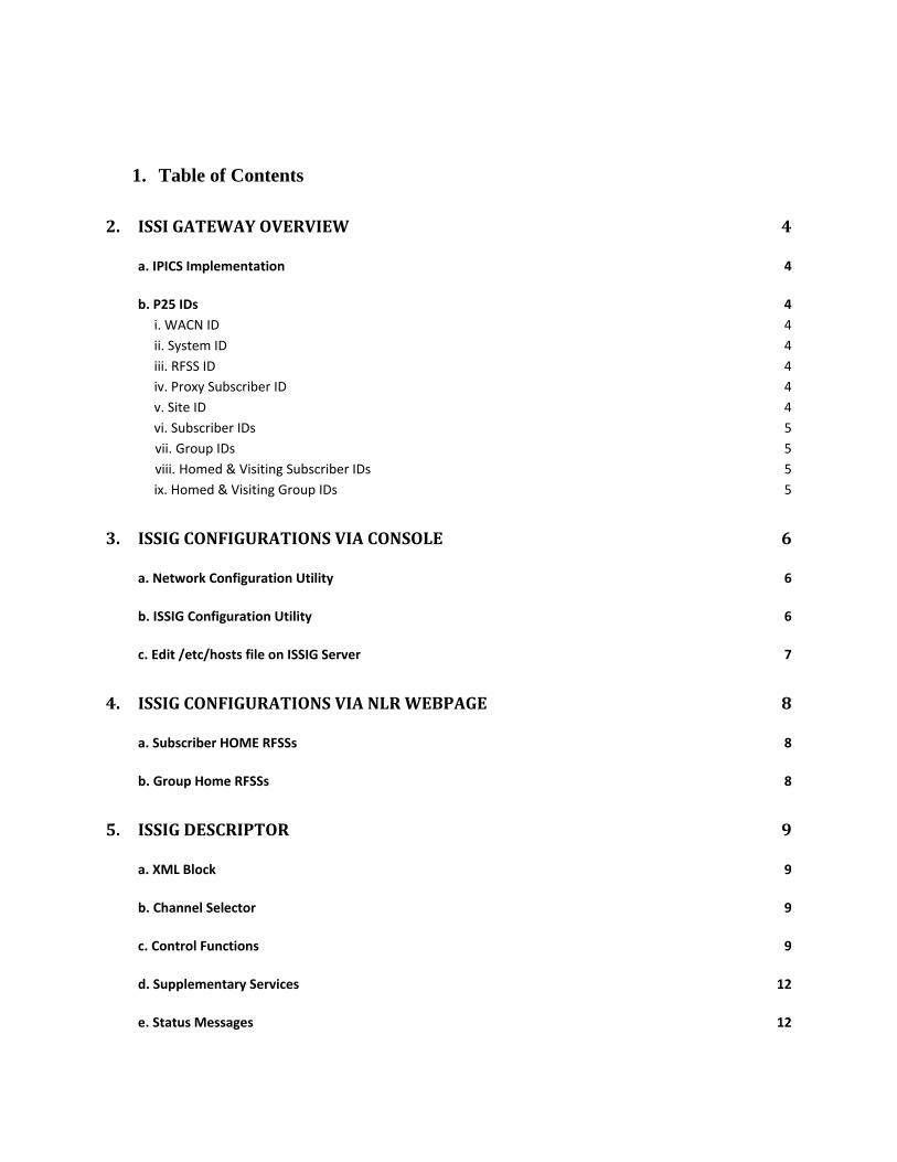
1. Table of Contents
2. ISSIGATEWAYOVERVIEW 4
a. IPICS Implementation 4
b. P25 IDs 4
i. WACN ID 4
ii. System ID 4
iii. RFSS ID 4
iv. Proxy Subscriber ID 4
v. Site ID 4
vi. Subscriber IDs 5
vii. Group IDs 5
viii. Homed & Visiting Subscriber IDs 5
ix. Homed & Visiting Group IDs 5
3. ISSIGCONFIGURATIONSVIACONSOLE 6
a. Network Configuration Utility 6
b. ISSIG Configuration Utility 6
c. Edit /etc/hosts file on ISSIG Server 7
4. ISSIGCONFIGURATIONSVIANLRWEBPAGE 8
a. Subscriber HOME RFSSs 8
b. Group Home RFSSs 8
5. ISSIGDESCRIPTOR 9
a. XML Block 9
b. Channel Selector 9
c. Control Functions 9
d. Supplementary Services 12
e. Status Messages 12
f. Status Updates 12
6. PROVISIONINGTHEISSIGINIPICSSERVER 13
a. Add ISSIG (as a radio) 13
b. Configure ISSIG Parameters 13
c. Verify Successful Addition of ISSIG 13
d. Channel Selectors, Control Functions & Supplementary Services 14
e. Provisioning P25 Channels 15
f. Assigning P25 Subscriber Unit IDs to IPICS Users 16
7. ISSIGINTEROPERABILITYONANIDC 19
a. P25 Channel Modes 19
b. P25 Supplementary Services 19
c. P25 Channel Details Page 19
d. P25 Gateway Mode 22
e. Unit to Unit Calls 22
f. Supplementary Services 23
g. Call Alert 23
h. Radio Check 24
i. Radio Detach 24
j. Radio Inhibit/Uninhibit 25
k. Remote Monitor 26
l. Short Message 26
m. Status Query 27
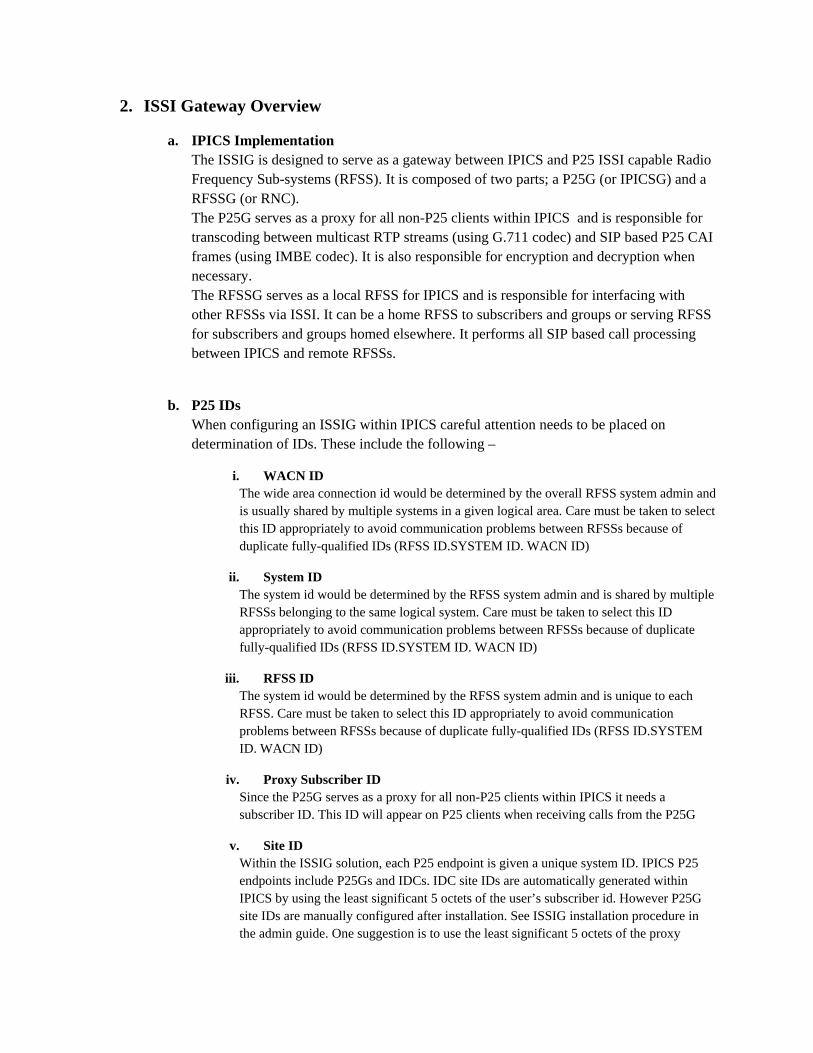
2. ISSI Gateway Overview
a. IPICS Implementation The ISSIG is designed to serve as a gateway between IPICS and P25 ISSI capable Radio Frequency Sub-systems (RFSS). It is composed of two parts; a P25G (or IPICSG) and a RFSSG (or RNC). The P25G serves as a proxy for all non-P25 clients within IPICS and is responsible for transcoding between multicast RTP streams (using G.711 codec) and SIP based P25 CAI frames (using IMBE codec). It is also responsible for encryption and decryption when necessary. The RFSSG serves as a local RFSS for IPICS and is responsible for interfacing with other RFSSs via ISSI. It can be a home RFSS to subscribers and groups or serving RFSS for subscribers and groups homed elsewhere. It performs all SIP based call processing between IPICS and remote RFSSs.
b. P25 IDs When configuring an ISSIG within IPICS careful attention needs to be placed on determination of IDs. These include the following –
i. WACN ID The wide area connection id would be determined by the overall RFSS system admin and is usually shared by multiple systems in a given logical area. Care must be taken to select this ID appropriately to avoid communication problems between RFSSs because of duplicate fully-qualified IDs (RFSS ID.SYSTEM ID. WACN ID)
ii. System ID The system id would be determined by the RFSS system admin and is shared by multiple RFSSs belonging to the same logical system. Care must be taken to select this ID appropriately to avoid communication problems between RFSSs because of duplicate fully-qualified IDs (RFSS ID.SYSTEM ID. WACN ID)
iii. RFSS ID The system id would be determined by the RFSS system admin and is unique to each RFSS. Care must be taken to select this ID appropriately to avoid communication problems between RFSSs because of duplicate fully-qualified IDs (RFSS ID.SYSTEM ID. WACN ID)
iv. Proxy Subscriber ID Since the P25G serves as a proxy for all non-P25 clients within IPICS it needs a subscriber ID. This ID will appear on P25 clients when receiving calls from the P25G
v. Site ID Within the ISSIG solution, each P25 endpoint is given a unique system ID. IPICS P25 endpoints include P25Gs and IDCs. IDC site IDs are automatically generated within IPICS by using the least significant 5 octets of the user’s subscriber id. However P25G site IDs are manually configured after installation. See ISSIG installation procedure in the admin guide. One suggestion is to use the least significant 5 octets of the proxy
subscriber id assigned to the P25G. This follows the automatic site ID generation for IDC involved in native P25 calls.
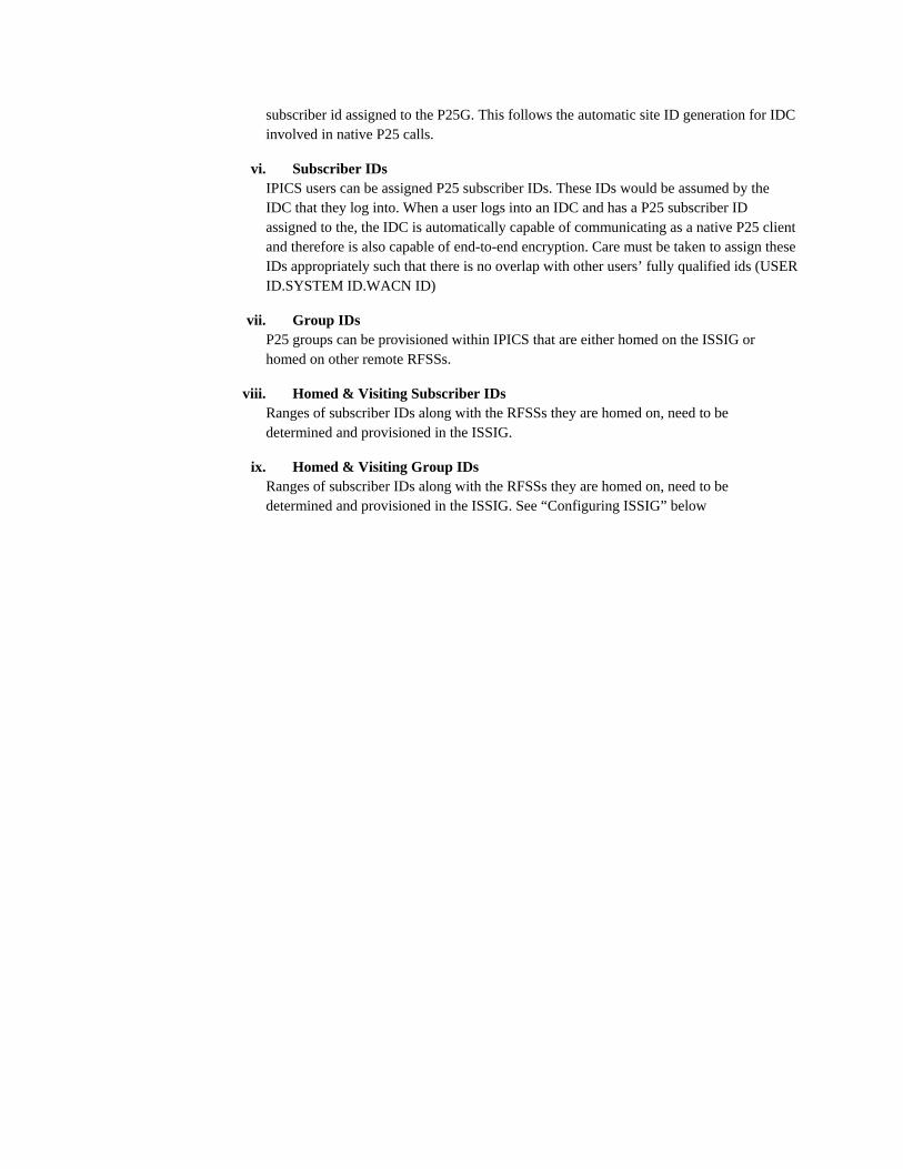
vi. Subscriber IDs IPICS users can be assigned P25 subscriber IDs. These IDs would be assumed by the IDC that they log into. When a user logs into an IDC and has a P25 subscriber ID assigned to the, the IDC is automatically capable of communicating as a native P25 client and therefore is also capable of end-to-end encryption. Care must be taken to assign these IDs appropriately such that there is no overlap with other users’ fully qualified ids (USER ID.SYSTEM ID.WACN ID)
vii. Group IDs P25 groups can be provisioned within IPICS that are either homed on the ISSIG or homed on other remote RFSSs.
viii. Homed & Visiting Subscriber IDs Ranges of subscriber IDs along with the RFSSs they are homed on, need to be determined and provisioned in the ISSIG.
ix. Homed & Visiting Group IDs Ranges of subscriber IDs along with the RFSSs they are homed on, need to be determined and provisioned in the ISSIG. See “Configuring ISSIG” below
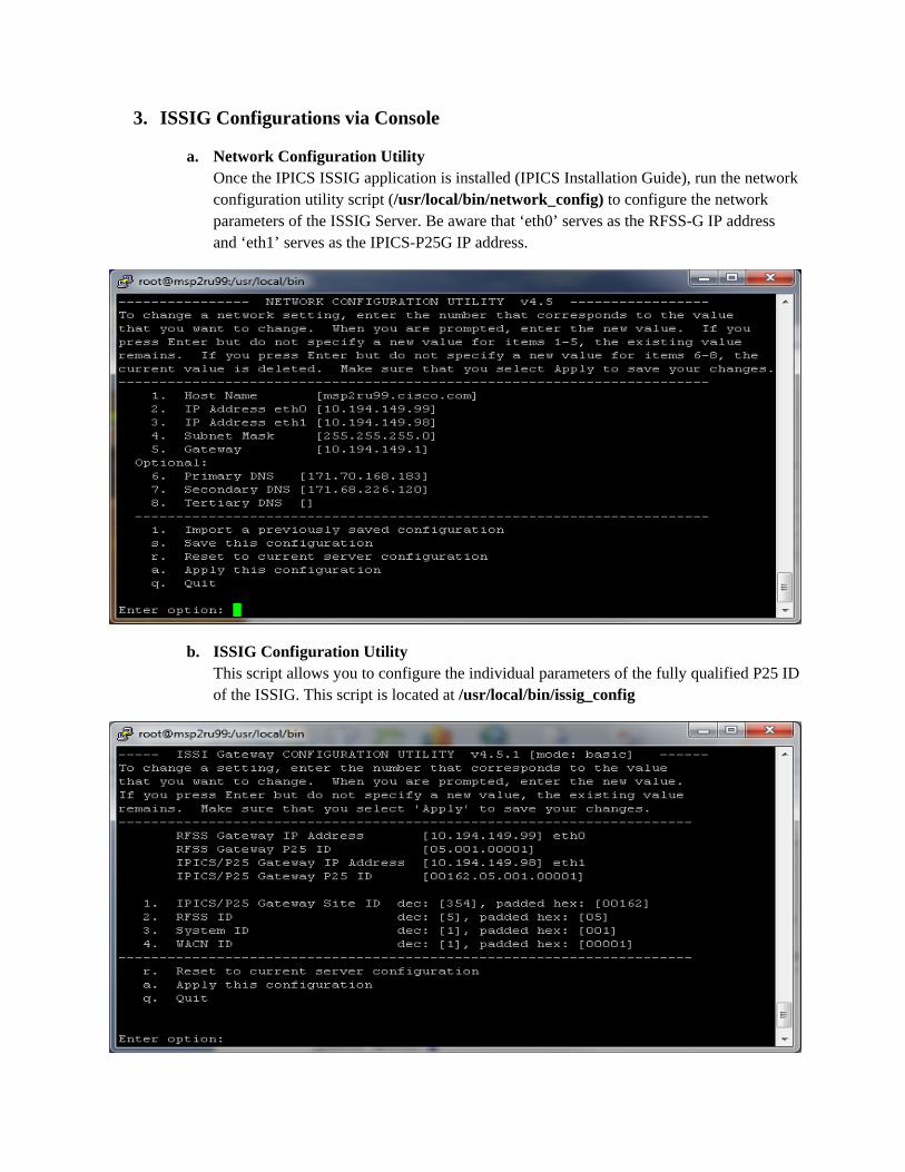
3. ISSIG Configurations via Console
a. Network Configuration Utility Once the IPICS ISSIG application is installed (IPICS Installation Guide), run the network configuration utility script (/usr/local/bin/network_config) to configure the network parameters of the ISSIG Server. Be aware that ‘eth0’ serves as the RFSS-G IP address and ‘eth1’ serves as the IPICS-P25G IP address.
b. ISSIG Configuration Utility This script allows you to configure the individual parameters of the fully qualified P25 ID of the ISSIG. This script is located at /usr/local/bin/issig_config
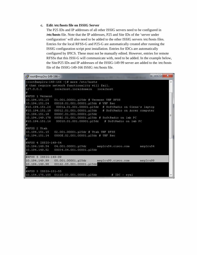
c. Edit /etc/hosts file on ISSIG Server The P25 IDs and IP addresses of all other ISSIG servers need to be configured in /etc/hosts file. Note that the IP addresses, P25 and Site IDs of the ‘server under configuration’ will also need to be added to the other ISSIG servers /etc/hosts files. Entries for the local RFSS-G and P25-G are automatically created after running the ISSIG configuration script post installation. Entries for IDCs are automatically configured by IPICS. These must not be manually edited. However, entries for remote RFSSs that this ISSI-G will communicate with, need to be added. In the example below, the Site/P25 IDs and IP addresses of the ISSIG-149-99 server are added to the /etc/hosts file of the ISSIG-149-166 ISSIG /etc/hosts file.
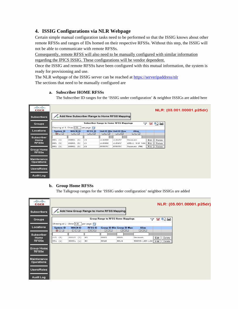
4. ISSIG Configurations via NLR Webpage Certain simple manual configuration tasks need to be performed so that the ISSIG knows about other remote RFSSs and ranges of IDs homed on their respective RFSSs. Without this step, the ISSIG will not be able to communicate with remote RFSSs. Consequently, remote RFSS will also need to be manually configured with similar information regarding the IPICS ISSIG. These configurations will be vendor dependent. Once the ISSIG and remote RFSSs have been configured with this mutual information, the system is ready for provisioning and use. The NLR webpage of the ISSIG server can be reached at https://serveripaddress/nlr The sections that need to be manually configured are
a. Subscriber HOME RFSSs The Subscriber ID ranges for the ‘ISSIG under configuration’ & neighbor ISSIGs are added here
b. Group Home RFSSs The Talkgroup ranges for the ‘ISSIG under configuration’ neighbor ISSIGs are added
5. ISSIG Descriptor Before an ISSIG is provisioned within the IPICS Server, a descriptor needs to be created that describes groups that a given ISSIG may need to affiliate and supplementary services that are available via the ISSIG. An example ISSIG descriptor is available on the IPICS Server in Configuration > Descriptors. Below is an explanation of the format of the descriptor (XML file).
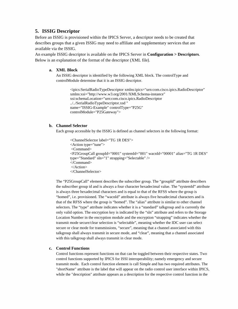
a. XML Block An ISSIG descriptor is identified by the following XML block. The controlType and controlModule determine that it is an ISSIG descriptor.
<ipics:SerialRadioTypeDescriptor xmlns:ipics="urn:com.cisco.ipics.RadioDescriptor" xmlns:xsi="http://www.w3.org/2001/XMLSchema-instance" xsi:schemaLocation="urn:com.cisco.ipics.RadioDescriptor ../../SerialRadioTypeDescriptor.xsd " name="ISSIG-Example" controlType="P25G" controlModule="P25Gateway">
b. Channel Selector Each group accessible by the ISSIG is defined as channel selectors in the following format:
<ChannelSelector label="TG 1R DES"> <Action type="tune"> <Command>
<P25GroupCall groupId="0001" systemId="001" wacnId="00001" alias="TG 1R DES" type="Standard" sln="1" strapping="Selectable" />
</Command> </Action>
</ChannelSelector>
The “P25GroupCall” element describes the subscriber group. The “groupId” attribute describers the subscriber group id and is always a four character hexadecimal value. The “systemId” attribute is always three hexadecimal characters and is equal to that of the RFSS where the group is “homed”, i.e. provisioned. The “wacnId” attribute is always five hexadecimal characters and is that of the RFSS where the group is “homed”. The “alias” attribute is similar to other channel selectors. The “type” attribute indicates whether it is a “standard” talkgroup and is currently the only valid option. The encryption key is indicated by the “sln” attribute and refers to the Storage Location Number in the encryption module and the encryption “strapping” indicates whether the transmit mode secure/clear selection is “selectable”, meaning whether the IDC user can select secure or clear mode for transmissions, “secure”, meaning that a channel associated with this talkgroup shall always transmit in secure mode, and “clear”, meaning that a channel associated with this talkgroup shall always transmit in clear mode.
c. Control Functions Control functions represent functions on that can be toggled between their respective states. Two control functions supported by IPICS for ISSI interoperability; namely emergency and secure transmit mode. Each control function element is call Simple and has two required attributes. The "shortName" attribute is the label that will appear on the radio control user interface within IPICS, while the "description" attribute appears as a description for the respective control function in the
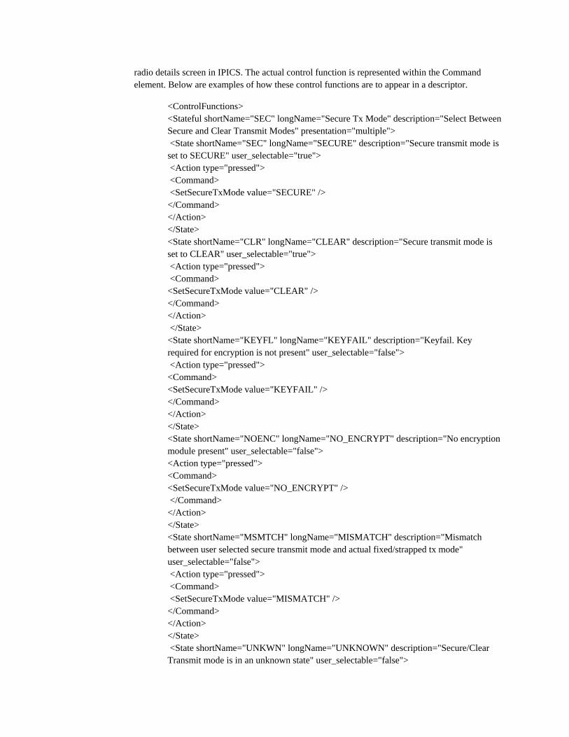
radio details screen in IPICS. The actual control function is represented within the Command element. Below are examples of how these control functions are to appear in a descriptor.
<ControlFunctions> <Stateful shortName="SEC" longName="Secure Tx Mode" description="Select Between Secure and Clear Transmit Modes" presentation="multiple"> <State shortName="SEC" longName="SECURE" description="Secure transmit mode is set to SECURE" user_selectable="true"> <Action type="pressed"> <Command> <SetSecureTxMode value="SECURE" />
</Command> </Action> </State>
<State shortName="CLR" longName="CLEAR" description="Secure transmit mode is set to CLEAR" user_selectable="true">
<Action type="pressed"> <Command> <SetSecureTxMode value="CLEAR" /> </Command> </Action> </State> <State shortName="KEYFL" longName="KEYFAIL" description="Keyfail. Key required for encryption is not present" user_selectable="false"> <Action type="pressed"> <Command> <SetSecureTxMode value="KEYFAIL" /> </Command> </Action> </State>
<State shortName="NOENC" longName="NO_ENCRYPT" description="No encryption module present" user_selectable="false">
<Action type="pressed"> <Command> <SetSecureTxMode value="NO_ENCRYPT" /> </Command> </Action> </State>
<State shortName="MSMTCH" longName="MISMATCH" description="Mismatch between user selected secure transmit mode and actual fixed/strapped tx mode" user_selectable="false">
<Action type="pressed"> <Command> <SetSecureTxMode value="MISMATCH" /> </Command> </Action> </State>
<State shortName="UNKWN" longName="UNKNOWN" description="Secure/Clear Transmit mode is in an unknown state" user_selectable="false">
<Action type="pressed"> <Command> <SetSecureTxMode value="UNKNOWN" /> </Command> </Action> </State>
<State shortName="UNSPRT" longName="UNSUPPORTED" description="Encryption is not supported" user_selectable="false">
<Action type="pressed"> <Command> <SetSecureTxMode value="UNSUPPORTED" /> </Command> </Action> </State>
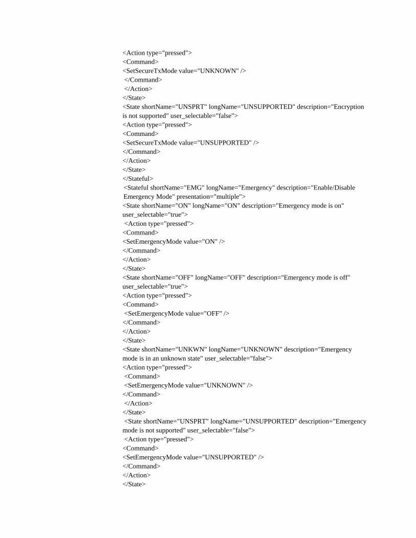
</Stateful> <Stateful shortName="EMG" longName="Emergency" description="Enable/Disable Emergency Mode" presentation="multiple"> <State shortName="ON" longName="ON" description="Emergency mode is on" user_selectable="true">
<Action type="pressed"> <Command> <SetEmergencyMode value="ON" /> </Command> </Action> </State>
<State shortName="OFF" longName="OFF" description="Emergency mode is off" user_selectable="true">
<Action type="pressed"> <Command> <SetEmergencyMode value="OFF" /> </Command> </Action> </State>
<State shortName="UNKWN" longName="UNKNOWN" description="Emergency mode is in an unknown state" user_selectable="false">
<Action type="pressed"> <Command> <SetEmergencyMode value="UNKNOWN" /> </Command> </Action> </State>
<State shortName="UNSPRT" longName="UNSUPPORTED" description="Emergency mode is not supported" user_selectable="false">
<Action type="pressed"> <Command> <SetEmergencyMode value="UNSUPPORTED" /> </Command> </Action> </State>
</Stateful> </ControlFunctions>
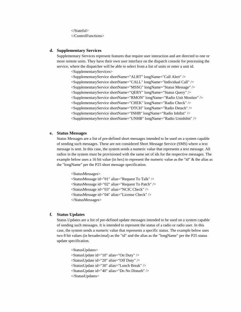
d. Supplementary Services Supplementary Services represent features that require user interaction and are directed to one or more remote units. They have their own user interface on the dispatch console for processing the service, where the dispatcher will be able to select from a list of units or enter a unit id.
<SupplementaryServices> <SupplementaryService shortName="ALRT" longName="Call Alert" /> <SupplementaryService shortName="CALL" longName="Individual Call" /> <SupplementaryService shortName="MSSG" longName="Status Message" /> <SupplementaryService shortName="QERY" longName="Status Query" /> <SupplementaryService shortName="RMON" longName="Radio Unit Monitor" /> <SupplementaryService shortName="CHEK" longName="Radio Check" /> <SupplementaryService shortName="DTCH" longName="Radio Detach" /> <SupplementaryService shortName="INHB" longName="Radio Inhibit" /> <SupplementaryService shortName="UNHB" longName="Radio Uninhibit" />
e. Status Messages Status Messages are a list of pre-defined short messages intended to be used on a system capable of sending such messages. These are not considered Short Message Service (SMS) where a text message is sent. In this case, the system sends a numeric value that represents a text message. All radios in the system must be provisioned with the same set of ids for the respective messages. The example below uses a 16 bit value (in hex) to represent the numeric value as the "id" & the alias as the "longName" per the P25 short message specification.
<StatusMessages> <StatusMessage id="01" alias="Request To Talk" /> <StatusMessage id="02" alias="Request To Patch" /> <StatusMessage id="03" alias="NCIC Check" /> <StatusMessage id="04" alias="License Check" /> </StatusMessages>
f. Status Updates Status Updates are a list of pre-defined update messages intended to be used on a system capable of sending such messages. It is intended to represent the status of a radio or radio user. In this case, the system sends a numeric value that represents a specific status. The example below uses two 8 bit values (in hexadecimal) as the "id" and the alias as the "longName" per the P25 status update specification.
<StatusUpdates> <StatusUpdate id="10" alias="On Duty" /> <StatusUpdate id="20" alias="Off Duty" /> <StatusUpdate id="30" alias="Lunch Break" /> <StatusUpdate id="40" alias="Do No Disturb" /> </StatusUpdates>
6. Provisioning the ISSIG in IPICS Server
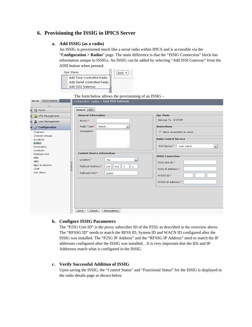
a. Add ISSIG (as a radio) An ISSIG is provisioned much like a serial radio within IPICS and is accessible via the “Configuration > Radios” page. The main difference is that the “ISSIG Connection” block has information unique to ISSIGs. An ISSIG can be added by selecting “Add ISSI Gateway” from the ADD button when pressed.
The form below allows the provisioning of an ISSIG –
b. Configure ISSIG Parameters The “P25G Unit ID” is the proxy subscriber ID of the P25G as described in the overview above. The “RFSSG ID” needs to match the RFSS ID, System ID and WACN ID configured after the ISSIG was installed. The “P25G IP Address” and the “RFSSG IP Address” need to match the IP addresses configured after the ISSIG was installed. . It is very important that the IDs and IP Addresses match what is configured in the ISSIG.
c. Verify Successful Addition of ISSIG Upon saving the ISSIG, the “Control Status” and “Functional Status” for the ISSIG is displayed in the radio details page as shown below
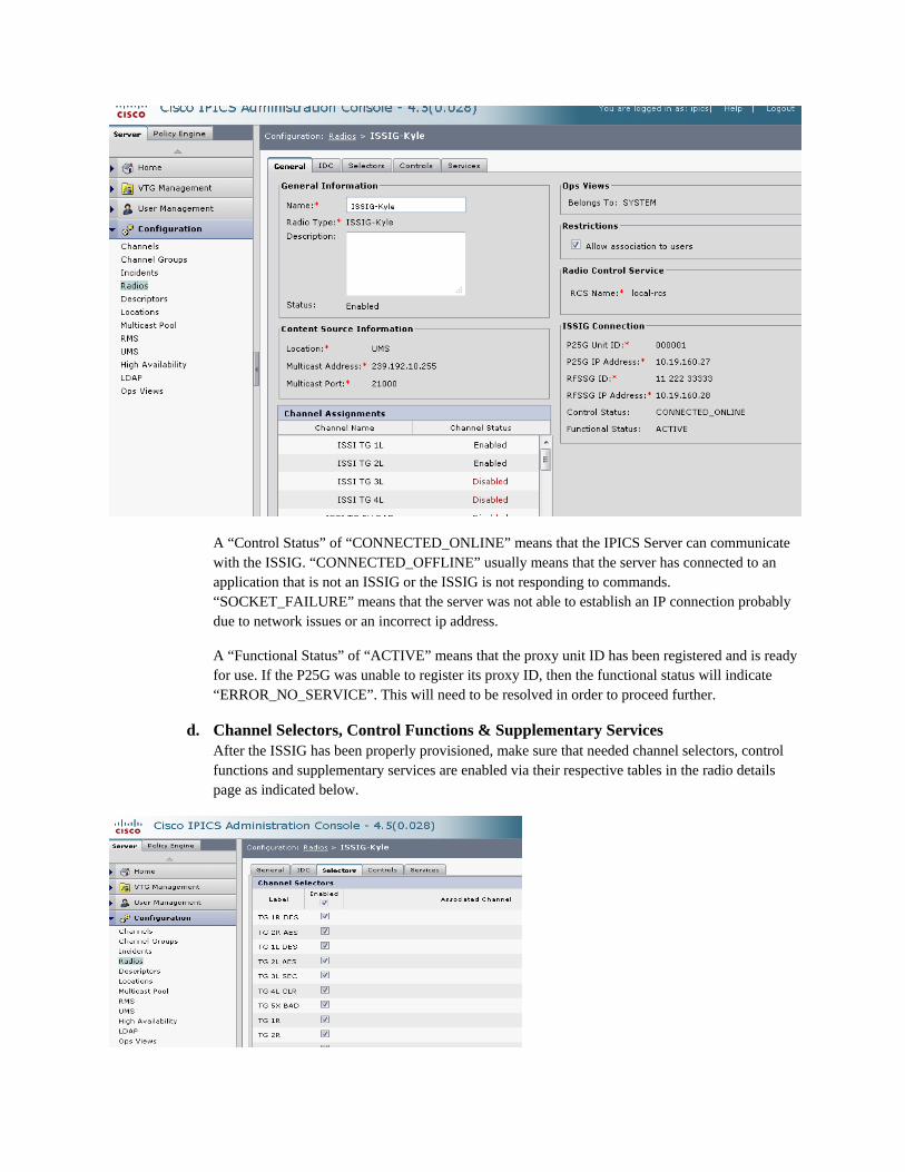
A “Control Status” of “CONNECTED_ONLINE” means that the IPICS Server can communicate with the ISSIG. “CONNECTED_OFFLINE” usually means that the server has connected to an application that is not an ISSIG or the ISSIG is not responding to commands. “SOCKET_FAILURE” means that the server was not able to establish an IP connection probably due to network issues or an incorrect ip address.
A “Functional Status” of “ACTIVE” means that the proxy unit ID has been registered and is ready for use. If the P25G was unable to register its proxy ID, then the functional status will indicate “ERROR_NO_SERVICE”. This will need to be resolved in order to proceed further.
d. Channel Selectors, Control Functions & Supplementary Services After the ISSIG has been properly provisioned, make sure that needed channel selectors, control functions and supplementary services are enabled via their respective tables in the radio details page as indicated below.
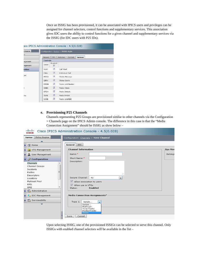
Once an ISSIG has been provisioned, it can be associated with IPICS users and privileges can be assigned for channel selectors, control functions and supplementary services. This association gives IDC users the ability to control functions for a given channel and supplementary services via the ISSIG (for IDC users with P25 IDs).
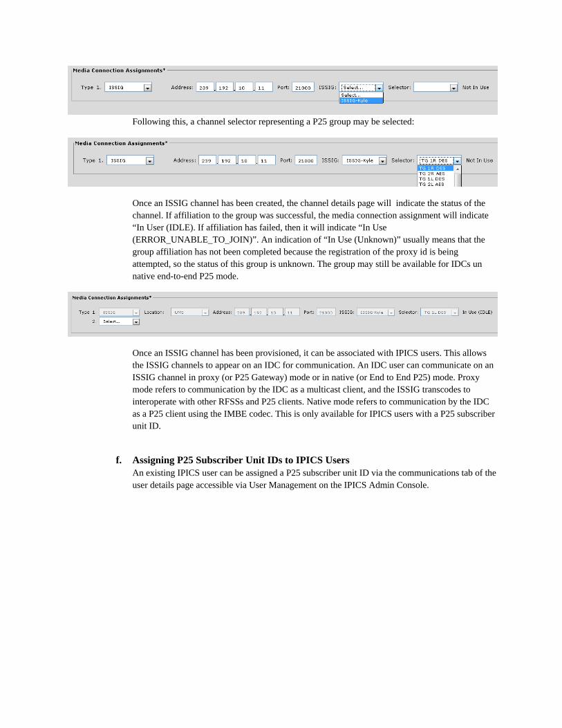
e. Provisioning P25 Channels Channels representing P25 Groups are provisioned similar to other channels via the Configuration > Channels page on the IPICS Admin console. The difference in this case is that the “Media Connection Assignment” should be ISSIG as show below –
Upon selecting ISSIG, one of the provisioned ISSIGs can be selected to serve this channel. Only ISSIGs with enabled channel selectors will be available in the list –
Following this, a channel selector representing a P25 group may be selected:
Once an ISSIG channel has been created, the channel details page will indicate the status of the channel. If affiliation to the group was successful, the media connection assignment will indicate “In User (IDLE). If affiliation has failed, then it will indicate “In Use (ERROR_UNABLE_TO_JOIN)”. An indication of “In Use (Unknown)” usually means that the group affiliation has not been completed because the registration of the proxy id is being attempted, so the status of this group is unknown. The group may still be available for IDCs un native end-to-end P25 mode.
Once an ISSIG channel has been provisioned, it can be associated with IPICS users. This allows the ISSIG channels to appear on an IDC for communication. An IDC user can communicate on an ISSIG channel in proxy (or P25 Gateway) mode or in native (or End to End P25) mode. Proxy mode refers to communication by the IDC as a multicast client, and the ISSIG transcodes to interoperate with other RFSSs and P25 clients. Native mode refers to communication by the IDC as a P25 client using the IMBE codec. This is only available for IPICS users with a P25 subscriber unit ID.
f. Assigning P25 Subscriber Unit IDs to IPICS Users An existing IPICS user can be assigned a P25 subscriber unit ID via the communications tab of the user details page accessible via User Management on the IPICS Admin Console.
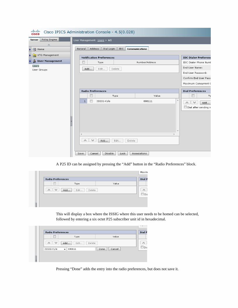
A P25 ID can be assigned by pressing the “Add” button in the “Radio Preferences” block.
This will display a box where the ISSIG where this user needs to be homed can be selected, followed by entering a six octet P25 subscriber unit id in hexadecimal.
Pressing “Done” adds the entry into the radio preferences, but does not save it.
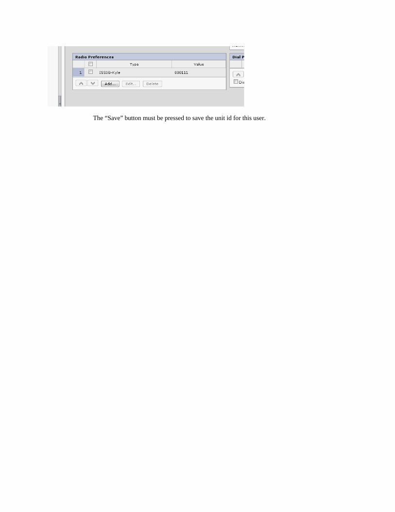
The “Save” button must be pressed to save the unit id for this user.
7. ISSIG Interoperability on an IDC
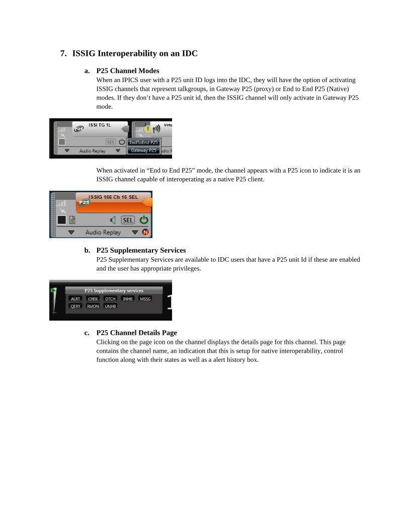
a. P25 Channel Modes When an IPICS user with a P25 unit ID logs into the IDC, they will have the option of activating ISSIG channels that represent talkgroups, in Gateway P25 (proxy) or End to End P25 (Native) modes. If they don’t have a P25 unit id, then the ISSIG channel will only activate in Gateway P25 mode.
When activated in “End to End P25” mode, the channel appears with a P25 icon to indicate it is an ISSIG channel capable of interoperating as a native P25 client.
b. P25 Supplementary Services P25 Supplementary Services are available to IDC users that have a P25 unit Id if these are enabled and the user has appropriate privileges.
c. P25 Channel Details Page Clicking on the page icon on the channel displays the details page for this channel. This page contains the channel name, an indication that this is setup for native interoperability, control function along with their states as well as a alert history box.
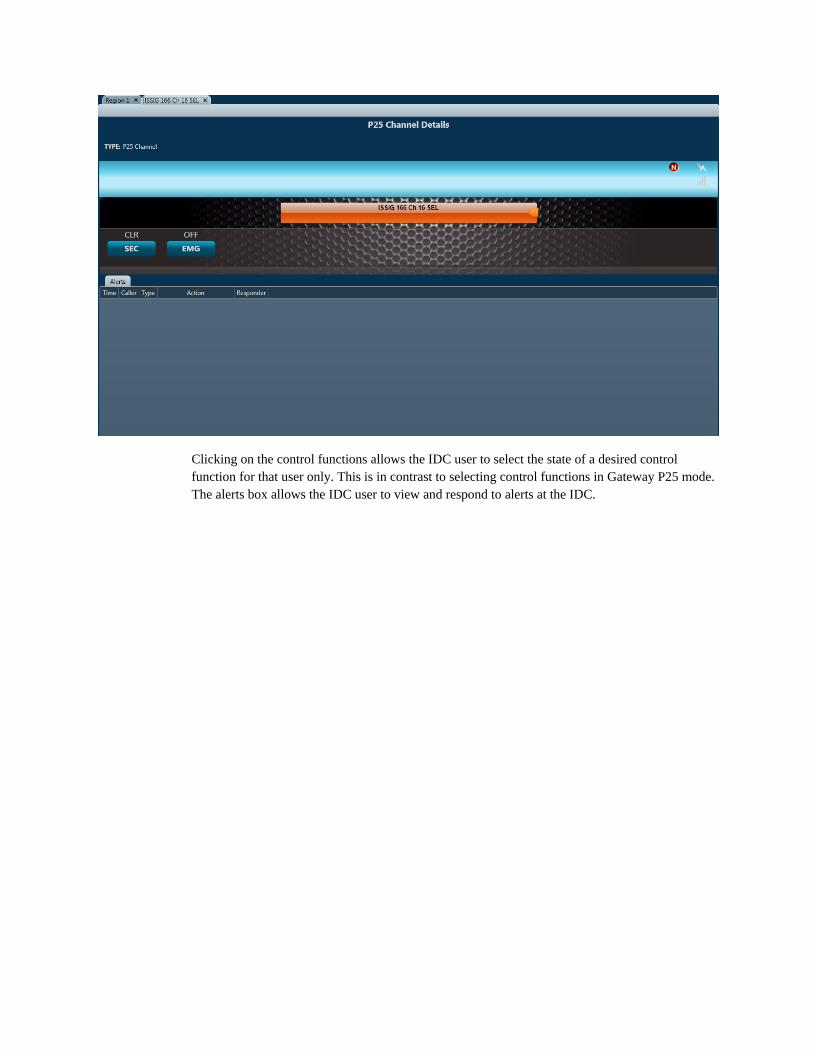
Clicking on the control functions allows the IDC user to select the state of a desired control function for that user only. This is in contrast to selecting control functions in Gateway P25 mode. The alerts box allows the IDC user to view and respond to alerts at the IDC.
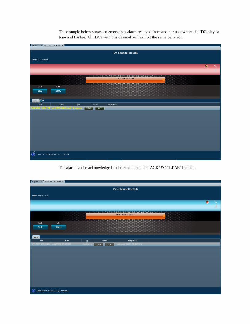
The example below shows an emergency alarm received from another user where the IDC plays a tone and flashes. All IDCs with this channel will exhibit the same behavior.
The alarm can be acknowledged and cleared using the ‘ACK’ & ‘CLEAR’ buttons.
Other IDC users will also see the alarm information and their IDCs will stop playing the audible emergency alarm when acknowledged and end the flashing when cleared.
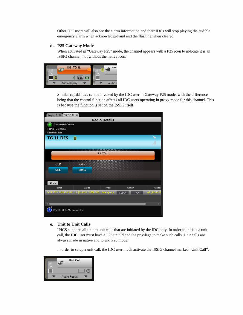
d. P25 Gateway Mode When activated in “Gateway P25” mode, the channel appears with a P25 icon to indicate it is an ISSIG channel, not without the native icon.
Similar capabilities can be invoked by the IDC user in Gateway P25 mode, with the difference being that the control function affects all IDC users operating in proxy mode for this channel. This is because the function is set on the ISSIG itself.
e. Unit to Unit Calls IPICS supports all unit to unit calls that are initiated by the IDC only. In order to initiate a unit call, the IDC user must have a P25 unit id and the privilege to make such calls. Unit calls are always made in native end to end P25 mode.
In order to setup a unit call, the IDC user much activate the ISSIG channel marked “Unit Call”.
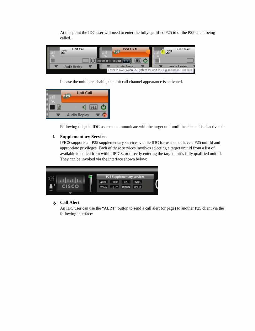
At this point the IDC user will need to enter the fully qualified P25 id of the P25 client being called.
In case the unit is reachable, the unit call channel appearance is activated.
Following this, the IDC user can communicate with the target unit until the channel is deactivated.
f. Supplementary Services IPICS supports all P25 supplementary services via the IDC for users that have a P25 unit Id and appropriate privileges. Each of these services involves selecting a target unit id from a list of available id culled from within IPICS, or directly entering the target unit’s fully qualified unit id. They can be invoked via the interface shown below:
g. Call Alert An IDC user can use the “ALRT” button to send a call alert (or page) to another P25 client via the following interface:
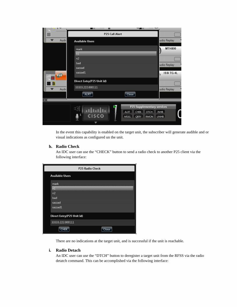
In the event this capability is enabled on the target unit, the subscriber will generate audible and or visual indications as configured un the unit.
h. Radio Check An IDC user can use the “CHECK” button to send a radio check to another P25 client via the following interface:
There are no indications at the target unit, and is successful if the unit is reachable.
i. Radio Detach An IDC user can use the “DTCH” button to deregister a target unit from the RFSS via the radio detatch command. This can be accomplished via the following interface:
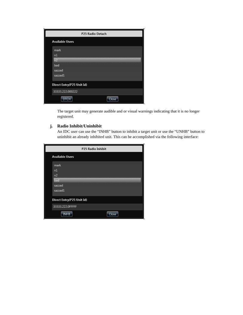
The target unit may generate audible and or visual warnings indicating that it is no longer registered.
j. Radio Inhibit/Uninhibit An IDC user can use the “INHB” button to inhibit a target unit or use the “UNHB” button to uninhibit an already inhibited unit. This can be accomplished via the following interface:
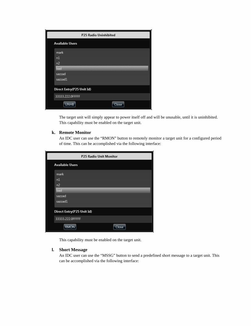
The target unit will simply appear to power itself off and will be unusable, until it is uninhibited. This capability must be enabled on the target unit.
k. Remote Monitor An IDC user can use the “RMON” button to remotely monitor a target unit for a configured period of time. This can be accomplished via the following interface:
This capability must be enabled on the target unit.
l. Short Message An IDC user can use the “MSSG” button to send a predefined short message to a target unit. This can be accomplished via the following interface:
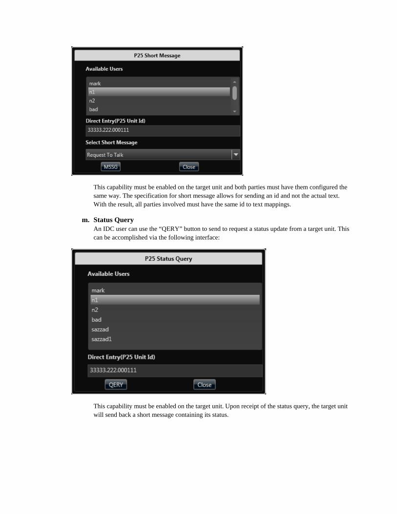
This capability must be enabled on the target unit and both parties must have them configured the same way. The specification for short message allows for sending an id and not the actual text. With the result, all parties involved must have the same id to text mappings.
m. Status Query An IDC user can use the “QERY” button to send to request a status update from a target unit. This can be accomplished via the following interface:
This capability must be enabled on the target unit. Upon receipt of the status query, the target unit will send back a short message containing its status.

Cisco and the Cisco logo are trademarks or registered trademarks of Cisco and/or its affiliates in the U.S. and other countries. To view a list of Cisco trademarks, go to this URL: www.cisco.com/go/trademarks. Third-party trademarks mentioned are the property of their respective owners. The use of the word partner does not imply a partnership relationship between Cisco and any other company. (1110R)
Any Internet Protocol (IP) addresses and phone numbers used in this document are not intended to be actual addresses and phone numbers. Any examples, command display output, network topology diagrams, and other figures included in the document are shown for illustrative purposes only. Any use of actual IP addresses or phone numbers in illustrative content is unintentional and coincidental.
© 2016 Cisco Systems, Inc. All rights reserved.