Embed Size (px)
Citation preview
ISSN 1068�798X, Russian Engineering Research, 2012, Vol. 32, No. 4, pp. 368–373. © Allerton Press, Inc., 2012.Original Russian Text © M.O. Nodel’man, B.M. Sukhovilov, 2012, published in Vestnik Mashinostroeniya, 2012, No. 4, pp. 72–76.
368
The cutting of plastic metals is associated withlocalization of the chips formed in front of the tool’scutting edge within a relatively narrow zone; with deepplastic deformation of the chip; and with simultaneousformation of new plastically deformed surfaces (thecutting surface and the cut surface), which are sites ofdisintegration and separation of the cut layer. The cutmargin (chip) moves over the tool’s front surface,overcoming the frictional forces at tool contact.
The tribological contact processes at the tool’sfront surface include capture, plastic deformation,cold working of the chip layer at the cutter, kinetic(external) friction, and, in certain conditions, adhe�sive phenomena at elastic chip–tool contact.
In industrial cutting, thermal phenomena in thechip�formation zones and at contact of the tool’s cut�ting edge with the blank and the chip have a significantinfluence on the deformation and contact processes.
Cutting differs from other manufacturing processesbased on metal deformation in that chip deformation,the resistance to cutting, and the thermal phenomena incutting are self�stabilizing [1, 2]. Self�organization of thecutting process depends on the machining conditions.
The influence of the machining conditions—including the properties of the tool and blank, the toolgeometry, and the cutting parameters—on the defor�mation, tribological, thermal, and force characteris�tics of the process is mediated by the influence on chipformation and tool–chip contact—specifically, on thechip�departure angle ν; the conditional shear angle β;the angle ω of cutting�force action; the chip shear ε;the tangential stress τβ referred to the conditionalshear plane; the mean chip–tool frictional angle; thechip shrinkage ξ; and the chip–tool contact length L.In other words, the overall influence depends on theinternal parameters (the dependence variables of thecutting process) and the relation between thoseparameters and the generalized configuration of cut�ting forces [3].
In the theory of metal cutting, the reliability of pre�dictions will depend on the physical models that rela�
tive the basic internal parameters (ν, ξ, L, θ, and ω) ofthe generalized configuration of cutting forces withthe machining factors. The assessment of the basicparameters (ν, ξ, L, θ) was discussed in [2].
We now consider the determination of the angle ωof cutting�force action, which characterizes the direc�tion of the cutting�force vector relative to the cutting�speed vector, in accordance with the generalized con�figuration of cutting forces; we take account here ofthe relation between ω and the machining factors.
Methods exist for the determination of ω on the basisof experimental data [1, 4]. For example, we may use theempirical dependence ω + β ≈ const or the empiricalrelation between ω and the parameters ξ, ε, and β at fixedν; this approach is only used in identifying the relation�ships between the cutting parameters [5]. In that case,ω is determined by dynamometric measurement of thecutting�force components, and the estimates obtainedare reliable. Therefore, in the present work, we comparethe calculated angle ωca of cutting�force action with dataobtained by dynamometric force measurements, in iden�tical turning conditions.
The mathematical model relating ω with themachining factors (the turning parameters and theblank’s load curve) is based on the thermodynamics ofirreversible deformation of a solid [6, 7]. In the turningof plastic metals with viscoplastic flow of the cut layer,predominantly at maximum productivity (maximumprofit), we consider the dissipation rate in chip forma�tion [2].
In the first approximation, we may write the dissi�pation rate in chip formation per unit volume of thecut layer in the following form, in accordance with [2]
(1)
Here K = Bv/30.5(n+1)α is the generalized machiningcharacteristic; v and a are, respectively, the cuttingspeed and cut�layer thickness; B and n are parameters
of the approximate equation σi = for loading ofthe blank; σi and ei are, respectively, the stress and
D K εn 1+ K1–( )K2.≈
Bein
Configuration of the Cutting�Force Vector in Turning Plastic MetalsM. O. Nodel’mana and B. M. Sukhovilovb
a Chelyabinstrument, Chelyabinskb South Ural State University, Chelyabinsk
e�mail: [email protected]
Abstract—A method is proposed for determining the angle of the cutting�force vector in turning plastic met�als by a hard�alloy tool at maximum productivity (maximum profit), on the basis of a mathematical model ofthe dissipation rate in chip formation as a function of the cutting parameters.
DOI: 10.3103/S1068798X12030173
RUSSIAN ENGINEERING RESEARCH Vol. 32 No. 4 2012
CONFIGURATION OF THE CUTTING�FORCE VECTOR IN TURNING PLASTIC METALS 369
strain intensities when τβ = σi/30.5 and ε = ei30.5; K1 =
0.34641/2.886752n characterizes the work of elasticdeformation in chip formation [8]; and
is the generalized internal cutting characteristic as afunction of ω and β.
The shear ε and angle β are determined from thebasic parameters ξ and ν by means of the familiar for�mulas [5, 2].
The influence of the machining conditions (v, a)and the blank (B, n) on the dissipation rate D in chipformation is now determined in free and constrainedturning of plastic metals in air, by T15K6 hard�alloycutters, for various front surfaces:
(1) a plane surface with front angle γ in the rangefrom –10° to 20°, when ν = γ;
(2) a double surface (λ = 0; ϕ = 44°; r = 1 × 10⁻³ m;γ = 5°; γφ = –5°; f = 2 × 10⁻⁴ m), when ν = 2°;
(3) a complex truncated surface with a recess(radius Rre and depth h) at the chip–tool contact sec�tion (λ = 0; ϕ = 44°–46°; r = 1 × 10⁻³ m; γ = 5°; γφ = ⎯5°;f = 1 × 10⁻⁴, 2 × 10⁻⁴ m, or 3 × 10⁻⁴ m; Rin = 12 × 10–4 m;h = 2 × 10⁻⁴ m), when ν ≈ 12°–13°.
Samples made of carbon steel and stainless steel—45 (170 HB), 70Г (255HB), 30XГT (196 HB),20X (187 HB), 20XH3A (163 HB), and 38XCA (187 HB)steel—are subjected to free transverse turning with n =0.08–0.15 and B = (882.6–1142.5) × 106 Pa. Samples of25XHBA (269 HB), 65Г (255 HB), 45X (255 HB),12X2H4A (187 HB), and 38XMЮA (255 HB) steel aresubjected to constrained longitudinal turning at n =0.085–0.156 and B = (863–1180) × 106 Pa.
For free transverse turning, we use cutters with aplane front surface (γ = –10°, –5°, 0°, 5°, 10°, 15°,
K2 1 ω βcottan+( )/ 1 β2
cot+( ) βcot ωtan–( )[ ]=
and 20°), in the following conditions: v = 2.583 m/s;b = (4.5–4.8) × 10–3 m; a = (0.15, 0.215, 0.305, 0.435,0.52) × 10–3 m.
For constrained longitudinal turning, we use cut�ters with a plane front surface (γ = –6°, 5°, 10°, and15°) and also with a double front surface and a com�plex truncated surface, in the following conditions:v = 0.8333, 1.166, 1.5, 1.833, 2.333, and 2.833 m/s;a = (0.196–0.4) × 10–3 m; b = (4.17–4.32) × 10–3 m(Tables 1 and 2).
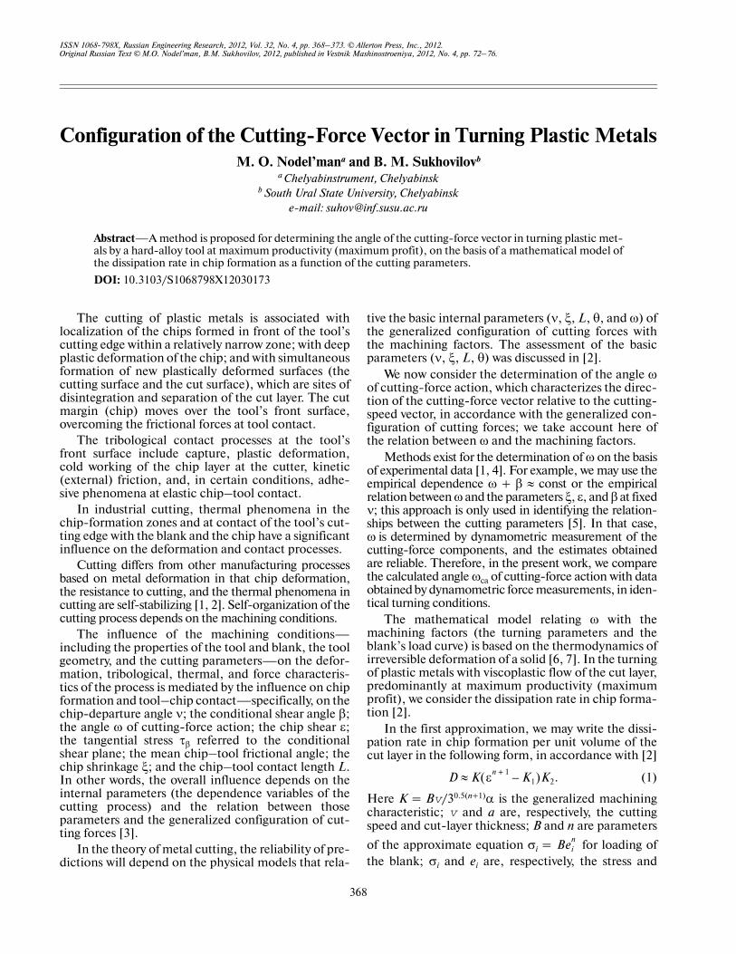
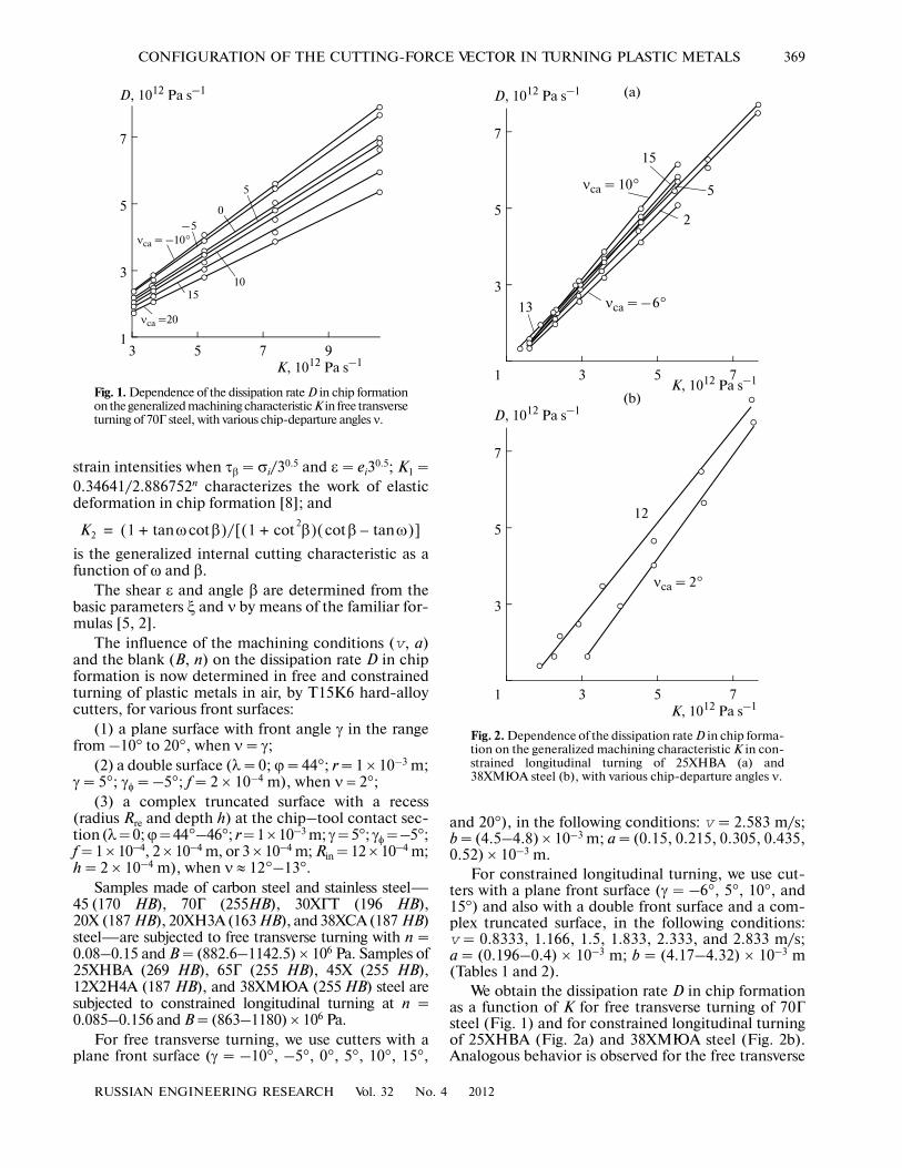
We obtain the dissipation rate D in chip formationas a function of K for free transverse turning of 70Гsteel (Fig. 1) and for constrained longitudinal turningof 25XHBA (Fig. 2a) and 38XMЮA steel (Fig. 2b).Analogous behavior is observed for the free transverse
3 5 7 9
3
5
7
K, 1012 Pa s–1
D, 1012 Pa s–1
1
νca = –10°–5
5
1015
0
νca =20
Fig. 1. Dependence of the dissipation rate D in chip formationon the generalized machining characteristic K in free transverseturning of 70Г steel, with various chip�departure angles ν.
1 3 5 7
3
5
7
K, 1012 Pa s–1
D, 1012 Pa s–1
1 3 5 7
3
5
7
K, 1012 Pa s–1
D, 1012 Pa s–1
νca = 2°
νca = 10°
νca = –6°
5
2
15
13
12
(b)
(a)
Fig. 2. Dependence of the dissipation rate D in chip forma�tion on the generalized machining characteristic K in con�strained longitudinal turning of 25XHBA (a) and38XMЮA steel (b), with various chip�departure angles ν.
370
RUSSIAN ENGINEERING RESEARCH Vol. 32 No. 4 2012
NODEL’MAN, SUKHOVILOV
turning of 20X, 38XCA, 45, 30XГT, and 20XH3A steelsamples; and for the constrained longitudinal turningof 45X, 65Г, and 12X2H4A steel samples.
The linear influence of K on D at fixed ν is evidentfrom the approximation of the empirical dependenceD = f(K) when ν = const by the formula Dca = +KcaK, where Dca is the calculated dissipation rate in
Dca'
chip formation for given K and ν; and Kca are the
calculated values of the free term and the coefficient in
the formula Dca = f(K, Kca, ) when ν ≈ const.
We obtain and Kca by the least�squares method
for free transverse turning and constrained longitudi�nal turning (Tables 3 and 4).
Dca'
Dca'
Dca'
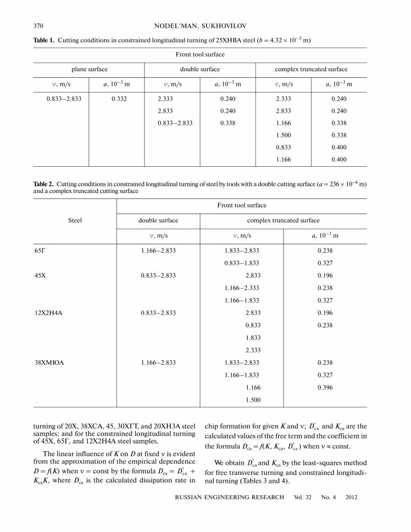
Table 2. Cutting conditions in constrained longitudinal turning of steel by tools with a double cutting surface (a = 236 × 10–6 m)and a complex truncated cutting surface
Steel
Front tool surface
double surface complex truncated surface
v, m/s v, m/s a, 10–3 m
65Г 1.166–2.833 1.833–2.833 0.238
0.833–1.833 0.327
45X 0.833–2.833 2.833 0.196
1.166–2.333 0.238
1.166–1.833 0.327
12X2H4A 0.833–2.833 2.833 0.196
0.833 0.238
1.833
2.333
38XMЮA 1.166–2.833 1.833–2.833 0.238
1.166–1.833 0.327
1.166 0.396
1.500
Table 1. Cutting conditions in constrained longitudinal turning of 25XHBA steel (b = 4.32 × 10⁻³ m)
Front tool surface
plane surface double surface complex truncated surface
v, m/s a, 10–3 m v, m/s a, 10–3 m v, m/s a, 10–3 m
0.833–2.833 0.332 2.333 0.240 2.333 0.240
2.833 0.240 2.833 0.240
0.833–2.833 0.338 1.166 0.338
1.500 0.338
0.833 0.400
1.166 0.400
RUSSIAN ENGINEERING RESEARCH Vol. 32 No. 4 2012
CONFIGURATION OF THE CUTTING�FORCE VECTOR IN TURNING PLASTIC METALS 371
Table 3. Characteristics of free transverse turning
Steel ν, deg 1012 Pa s–1 Kca Δω, deg δω* , %
–10 0.133554 0.737794 26.33–34.66 1.51/1.58
–5 0.147956 0.716232 24.25–32.25 2.11/1.16
0 0.191733 0.644418 19.58–28.00 2.79/1.58
70Г 5 0.165671 0.629208 16.75–25.00 1.63/1.43
10 0.129360 0.607768 13.83–23.66 4.17/6.99
15 0.243534 0.537014 10.83–19.08 2.74/3.94
20 0.307299 0.476093 7.50–15.25 1.97/1.72
–10 0.219948 0.669519 28.83–35.42 2.35/2.64
–5 0.255229 0.654546 28.00–34.08 2.24/3.27
0 –0.014180 0.667519 22.66–32.00 2.70/2.98
Steel 45 5 0.180206 0.590992 20.00–28.50 2.20/3.59
10 0.194604 0.564895 16.17–25.75 4.06/2.99
15 0.132107 0.520158 12.42–23.33 2.04/2.19
20 0.230752 0.466817 10.58–21.25 3.92/4.50
–10 0.263856 0.662285 31.25–36.50 3.35/2.50
–5 0.320563 0.623917 27.33–33.33 1.67/0.99
0 0.127171 0.638543 23.75–32.00 0.60/0.38
30XГT 5 0.165865 0.586043 21.17–28.00 1.96/1.72
10 0.080034 0.570452 17.50–26.00 1.89/3.09
15 –0.045583 0.557389 12.75–22.50 4.43/7.99
20 0.054624 0.513068 10.66–20.75 2.68/4.66
–10 0.431856 0.602912 29.33–36.33 3.73/3.30
–5 0.361768 0.615506 26.66–34.00 2.33/2.96
0 0.239696 0.604575 24.42–31.83 2.20/2.06
20X 5 0.367528 0.531079 20.08–28.25 3.30/3.41
10 0.343268 0.502929 17.33–25.75 7.38/5.87
15 0.158190 0.518922 13.66–23.66 13.80/6.59
20 0.242672 0.467356 11.75–20.66 11.70/8.99
–5 0.119248 0.729766 26.50–33.25 2.06/1.81
0 0.013235 0.717159 23.16–31.50 1.12/2.28
20XHЗA 5 0.139954 0.643924 20.33–28.33 1.42/1.58
10 0.188066 0.588588 17.75–25.33 2.57/2.37
15 0.186211 0.555082 15.83–23.25 2.51/3.55
20 0.092166 0.530949 12.08–20.92 1.96/1.99
–10 0.196301 0.705857 30.00–37.16 2.68/2.88
–5 0.370262 0.636747 26.92–33.66 5.66/4.30
0 0.304277 0.619396 24.50–31.75 3.75/4.63
38XCA 5 0.339355 0.559352 19.58–28.83 3.95/2.90
10 0.559182 0.488581 16.66–25.92 10.90/6.73
15 0.264221 0.505190 12.75–24.00 3.15/4.80
20 0.280528 0.469390 11.00�22.00 3.21/1.72
* Negative/positive values.
Dca' ,
372
RUSSIAN ENGINEERING RESEARCH Vol. 32 No. 4 2012
NODEL’MAN, SUKHOVILOV
Table 4. Characteristics of constrained longitudinal turning
V, deg ν, deg , 1012 Pa s–1 Kca Δω, deg δω*, %
25XHBA –625
101315
–0.181343 –0.192318 –0.349253 –0.384729
0.044776 –0.248051
0.9422641.0064101.0946301.1771500.9967731.092340
31.50–32.9226.25–29.5024.67–27.00 22.25–25.2523.17–23.6718.83–22.80
0.68/0.55 2.18/2.622.58/2.49 0.53/0.32 3.80/2.21 0.47/1.52
65Г 212
–0.8917070.150422
1.1705201.114910
24.92–27.5023.00–25.42
2.19/3.61 4.35/5.92
45X 212
–0.269035 –0.043564
0.9337031.143870
26.17–29.7524.83–25.67
2.50/2.63 8.25/5.63
12X2H4A 212
–0.693137 –0.367064
0.9183190.941065
29.50–33.33 27.83–30.66
1.35/1.29 2.44/2.09
38XMЮA 212
–1.5275400.076877
1.3548301.220800
27.58–28.58 24.83–25.75
2.40/2.47 4.84/6.25
* Negative/positive values.
Dca'
5 15 25 35
15
25
35
ωca, deg
ω, deg15 25 35
25
35
ωca, deg
ω, deg
(a)
(b)
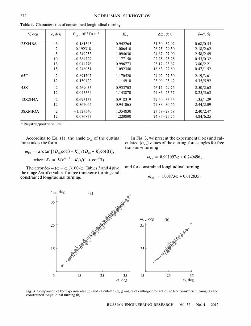
Fig. 3. Comparison of the experimental (ω) and calculated (ωca) angles of cutting�force action in free transverse turning (a) andconstrained longitudinal turning (b).
According to Eq. (1), the angle ωca of the cuttingforce takes the form
The error δω = (ω – ωca)100/ω. Tables 3 and 4 givethe range Δω of ω values for free transverse turning andconstrained longitudinal turning.
ωpa arc Dca β K3–cot( )/ Dca K3 βcot+( )[ ],tan=
where K3 K εn 1+ K1–( )/ 1 β
2cot+( ).=
In Fig. 3, we present the experimental (ω) and cal�culated (ωca) values of the cutting�force angles for freetransverse turning
and for constrained longitudinal turning
ωca 0.991097ω 0.249496,+=
ωca 1.00873ω 0.012835.+=
RUSSIAN ENGINEERING RESEARCH Vol. 32 No. 4 2012
CONFIGURATION OF THE CUTTING�FORCE VECTOR IN TURNING PLASTIC METALS 373
Analysis of the results demonstrates the reliabilityof the proposed approach and the adequacy of themodel for assessing the angle ω of cutting�force actionwhen plastic metals are cut by a hard�alloy tool atmaximum productivity (maximum profit).
REFERENCES
1. Rozenberg, A.M. and Eremin, A.N., Elementy teoriiprotsessa rezaniya metalla (Elements of a Theory ofMetal Cutting), Moscow: Mashgiz, 1956.
2. Nodel’man, M.O., Mekhanoobrabotka rezaniem.Osnovy teorii i praktika (Machining by Cutting: Theo�retical and Practical Principles), Chelyabinsk: Izd.REKPOL, 2005.
3. Nodel’man, M.O., Predicting the Rheological Param�eters of Plastic Metals with Self�Organization of Visco�
plastic Flow of the Cut Layer, Vestn. Mashinostr., 2009,no. 8, pp. 43–52.
4. Zorev, N.N., Voprosy mekhaniki protsessa rezaniya metalla(Mechanics of Metal Cutting), Moscow: Mashgiz,1956.
5. Bobrov, V.F., Razvitie nauki o rezanii metallov (Developingthe Science of Metal Cutting), Moscow: Mashinostro�enie, 1967.
6. de Groot, S.R., Thermodynamics of Irreversible Pro�cesses, Amsterdam: North Holland, 1951.
7. Ziegler, H., Some Extremum Principles in IrreversibleThermodynamics, with Application to ContinuumMechanics, in Progress in Solid Mechanics, Sneddon, I.N.and Hill, R., Eds., Amsterdam: North Holland, 1963,vol. 4.
8. Nodel’man, M.O., Assessing the Yield Point in CuttingPlastic Metals, Vestn. Mashinostr., 2009, no. 10,pp. 49–52.


![SIMPLIFICATION OF TURNING POINT PROBLEMS FOR …...1963] TURNING POINT PROBLEMS 103 constant rank r, and let b(z) be a vector function holomorphic at z = 0. If the equation (3.2) A(z)w(z)](https://img.pdfslide.us/doc/110x75/5f07889f7e708231d41d74ed/simplification-of-turning-point-problems-for-1963-turning-point-problems-103.jpg)