Embed Size (px)
Citation preview
CONFIGURATION MANUALVersion 14.00 - June 2015

Disclaimer
This manual and the information contained herein are the sole property of EVS BroadcastEquipment SA and/or its affiliates (EVS) and are provided “as is” without any expressed orimplied warranties, including, but not limited to, the implied warranties of merchantabilityand fitness for a particular purpose. In particular, EVS makes no warranty regarding theuse or the consequences of use of this manual and the information contained herein.Furthermore, EVS may not be held liable for any direct or indirect, incidental, punitive orconsequential loss, damage, cost or expense of any kind whatsoever and howsoeverresulting from the normal or abnormal use of this manual and the information containedherein, even if advised of the possibility of such loss, damage, cost or expense.
While every effort has beenmade to ensure that the information contained in this manualis accurate, up-to-date and reliable, EVS cannot be held liable for inaccuracies or errorsthat may appear in this publication. The information in this manual is furnished forinformational purpose and use only and subject to change without notice.
This manual cancels and replaces any previous versions thereof.
Copyright
Copyright © 2011-2015 EVS Broadcast Equipment SA. All rights reserved.
This manual may not be reproduced, transcribed, stored (in a database or an retrievalsystem), translated into any language, computer language, transmitted in any form or byany means – electronically, mechanically, printed, photocopied, optically, manually orotherwise – in whole or in part without the prior written consent of EVS.
Trademarks
All product and brand names are registered trademarks and trademarks of EVS or of theirrespective owners.
Improvement Requests
Your comments will help us improve the quality of the user documentation. Please sendimprovement requests, or report any error or inaccuracy on this user manual by e-mail [email protected].
Regional Contacts
Youwill find the full list of addresses and phone numbers on the following webpage:http://www.evs.com/contacts.
CONFIGURATION MANUAL XT3 Server 14.00
I

User Manuals on EVS Website
The latest version of the user manual, if any, and other user manuals on EVS products canbe found on the EVS download center, on the following webpage:http://www.evs.com/downloadcenter.
II
EVSBroadcast Equipment SA Issue 14.00.A - June 2015
Table of ContentsTABLE OF CONTENTS III
WHAT'S NEW? VII
1. INTRODUCTION 1
1.1. Introduction to the Configuration of EVS Servers 11.2. Introduction to theManual 41.3. Starting the EVS Server 41.4. Accessing theWeb-Based Interface 5
2. MULTICAM SETUP 6
2.1. Overview of User Interfaces 62.1.1. Overview of the Setup Areas 62.1.2. Navigability and Commands 9
2.2. Configuration Lines 112.2.1. Chapter Contents 112.2.2. Launching a Configuration 122.2.3. Editing a Configuration 132.2.4. Renaming Configuration Lines 152.2.5. Exporting and Importing Configuration Lines 162.2.6. Changing the Position of Configuration Lines 212.2.7. Copying, Pasting and Deleting Configuration Lines 21
2.3. Server Parameters 232.3.1. Chapter Contents 232.3.2. Assigning a Server Facility Name 232.3.3. Activating and Deactivating the Password Protection 242.3.4. Setting the Server LAN PC Address 262.3.5. Setting the Server Date and Time 272.3.6. Setting the Default Output To VGA/Video 292.3.7. Configuring Server Raids 29
2.4. Licenses andMaintenance 322.4.1. Overview onOptions Codes Management 322.4.2. Options Codes Management Window 332.4.3. Entering and Removing License Codes 35
2.5. Server Maintenance 372.5.1. Chapter Contents 372.5.2. Rebooting the EVS Server 372.5.3. Hardware Check 382.5.4. Clearing Video Disks 42
CONFIGURATION MANUAL XT3 Server 14.00
Table of Contents III
2.5.5. Record Train Maintenance 442.5.6. Importing and Exporting Keyword Files 462.5.7. Exporting Log Files 47
3. SUPPORTED CONFIGURATIONS 48
3.1. General Principles 483.1.1. About Supported Configurations 483.1.2. About Record and Play Channels 483.1.3. Channel Assignment Principles 503.1.4. About Extended Configurations 51
3.2. SD and HD Base Configurations 533.2.1. SD/HD Configurations (4U) 533.2.2. SD/HD Configurations (6U) 55
3.3. SLSM Configurations 583.3.1. General Information on Supermotion Configurations 583.3.2. SLSM Configurations (4U) 613.3.3. SLSM Configurations (6U) 70
3.4. 3D and 1080p Configurations 893.4.1. General Information on 3D Configurations 893.4.2. General Information on 1080p Configurations 903.4.3. Channel Assignment Principles with 3D/1080p 913.4.4. 3D/1080p Standard Configurations (4U) 923.4.5. 3D/1080p Standard Configurations (6U) 943.4.6. Channel Assignment Principles with 3D/1080p SLSM 983.4.7. 3D/1080p SLSM Configurations (4U) 993.4.8. 3D/1080p SLSM Configurations (6U) 103
3.5. 4K Configurations 1123.5.1. General Information on 4K Configurations 1123.5.2. 4K Configurations (4U) 1143.5.3. 4K Configurations (6U) 1153.5.4. 4K SLSM Configurations (6U) 116
4. MULTICAM CONFIGURATION 118
4.1. Overview on User Interfaces 1184.1.1. Introduction 1184.1.2. Overview of theMulticam ConfigurationWindow 1204.1.3. Navigating and Editing in theMulticam ConfigurationWindow 1244.1.4. Overview of the SetupMenus in the Remote Panel 1264.1.5. Navigating and Editing in the SetupMenus of the Remote Panel 1274.1.6. Required Application Reboot 128
4.2. Server Tab 1304.2.1. Overview 1304.2.2. Video Codecs and Reference 1314.2.3. Phase Definition Settings 1474.2.4. Interpolation Settings 148
IV Table of Contents
EVSBroadcast Equipment SA Issue 14.00.A - June 2015
4.2.5. PC LAN Settings 1494.3. Channels Tab 151
4.3.1. Overview 1514.3.2. Channels 1534.3.3. Audio 1754.3.4. Timecode and Data Insertion 198
4.4. Network Tab 2074.4.1. Overview 2074.4.2. SDTI Settings 2084.4.3. Gigabit Connection 2104.4.4. Gigabit IP Configuration 2134.4.5. Gigabit Prioritization Settings 215
4.5. Monitoring Tab 2184.5.1. Overview 2184.5.2. Multiviewer Settings 2194.5.3. OSD Settings 2234.5.4. Monitoring Settings 224
4.6. Protocol Tab 2274.6.1. Overview 2274.6.2. RS422 Protocols Settings 2294.6.3. Clip Identifiers 2304.6.4. Sony BVW Settings 2314.6.5. EditRec 2324.6.6. RS422 VarID Settings 239
4.7. GPI Tab 2434.7.1. Overview 2434.7.2. GPI Settings 2434.7.3. Tally Settings 248
4.8. Operation Tab 2504.8.1. Overview 2504.8.2. OSD Settings 2544.8.3. AudioMeters OSD Settings 2564.8.4. Clips Settings 2574.8.5. Playlist Settings 2634.8.6. Timeline Settings 2694.8.7. Protection Settings 2704.8.8. Keywords Settings 2724.8.9. Push Settings 2744.8.10. Audio Settings 2774.8.11. EVS Controller Settings 2794.8.12. HypermotionManagement 2864.8.13. Hypermotion Controller Settings 2874.8.14. Special Effects Settings 290
CONFIGURATION MANUAL XT3 Server 14.00
Table of Contents V
5. MONITORING 295
5.1. Server Monitoring 2955.1.1. Overview on Server MonitoringWindows 2955.1.2. General InformationWindow 2965.1.3. Raid and Disk Status Window 2985.1.4. Timecode Status Window 3015.1.5. TimecodeMonitoringWindow 3035.1.6. LogManagement 304
5.2. SDTI Network Monitoring 3065.2.1. Overview on SDTI Network MonitoringWindows 3065.2.2. SDTI Network Schema 3065.2.3. Hardware Error Counters 3085.2.4. Disconnecting aMachine from the XNet Network 308
5.3. Protocols 3095.3.1. Introduction 3095.3.2. Sony BVW75 3095.3.3. XTENDD35 3125.3.4. Odetics 3135.3.5. VDCP 314
6. TRUCK MANAGER PLUGIN 317
6.1. Introduction 3176.2. Plugin Overview 3186.3. Contextual Menu 3206.4. Configuration Area 3216.5. Server Area 3226.6. Channels Area 3246.7. Network Area 328
GLOSSARY 331
VI Table of Contents
EVSBroadcast Equipment SA Issue 14.00.A - June 2015
What's New?
In theMulticam Configurationmanual, the icon has been added on the leftmargin to highlight information on new and updated features in release 14.00.
NoteMulticam 14.00 is supported on EVS video servers fitted with V3X, H3X (orH3XP) and CODA75 (or A3X) boards. In this user manual, it is taken for grantedthat all EVS video servers are equipped with the above-mentioned boards.
The changes linked to new features in version 14.00 are listed below:
Changes in Conditions Requiring a Clear Video Disks, Clips, or Record Trains
• See section "Clearing Video Disks" on page 42
New Extended Configurations
• See section "About Supported Configurations" on page 48
• See section "About Extended Configurations" on page 51
• See section "SD/HD Configurations (6U)" on page 55
• See section "General Information on Supermotion Configurations" on page 58
• See section "SLSM Configurations (4U)" on page 61
• See section "SLSM Configurations (6U)" on page 70
• See section "General Information on 1080p Configurations" on page 90
• See section "3D/1080p SLSM Configurations (6U)" on page 103
TwinRec feature available on an XT3 4U server
• See section "TwinRec Feature" on page 158
Push Settings Adapted for the 12-Channel Feature
• See section "Push Settings" on page 274
Changes in Layout and Labels in Timecode and Data Insertion Settings
• See section "Timecode Settings" on page 198
• See section "SMPTE Package Settings" on page 204
• See section "Timecode Insertion Settings" on page 200
Support of 192 audio (12x16 mono/8x32 mono) and of MADI connectors
• See section "Audio and AudioMonitoring Settings" on page 175
• See section "Overview on Advanced Audio Settings" on page 180
• See section "Audio Output Settings" on page 186
• See section "Default Mapping for Audio Inputs andOutputs" on page 187
• See section "Modifying the Audio Routing or Type" on page 192
• See section "Number of Audio Tracks" on page 178
CONFIGURATION MANUAL XT3 Server 14.00
What'sNew? VII
The following changes unrelated to new features, and therefore not highlighted with theNew icon, have been brought to the configurationmanual:
Option to reinitiate the PC LAN connection with HS870 board
• See section "General InformationWindow" on page 296
VIII What'sNew?
EVSBroadcast Equipment SA Issue 14.00.A - June 2015
1. Introduction
1.1. Introduction to the Configuration ofEVS Servers
Configuration Module
TheMulticam Setup application is used for configuration andmaintenance operations onEVS video servers. It is also used to select which application to run, since EVS diskrecorders have the ability to run various dedicated applications (Video Server, SlowMotion, …).
The configurationmodule available fromMulticam 11.00 has been developed along thelines presented in this section.
Consolidation into a Single User Interface
The server can be fully configured from a single user interface.
The user interface includes:
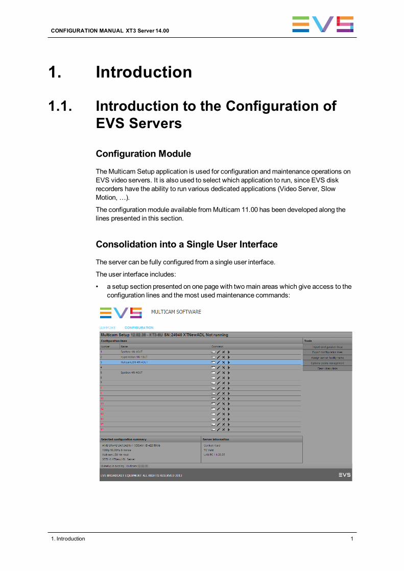
• a setup section presented on one page with twomain areas which give access to theconfiguration lines and themost usedmaintenance commands:
CONFIGURATION MANUAL XT3 Server 14.00
1. Introduction 1
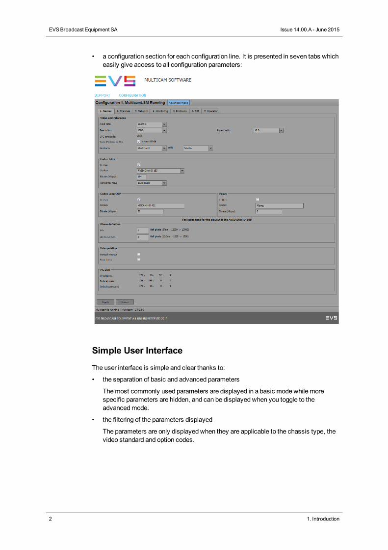
• a configuration section for each configuration line. It is presented in seven tabs whicheasily give access to all configuration parameters:
Simple User Interface
The user interface is simple and clear thanks to:
• the separation of basic and advanced parameters
Themost commonly used parameters are displayed in a basic mode while morespecific parameters are hidden, and can be displayed when you toggle to theadvancedmode.
• the filtering of the parameters displayed
The parameters are only displayed when they are applicable to the chassis type, thevideo standard and option codes.
2 1. Introduction
EVSBroadcast Equipment SA Issue 14.00.A - June 2015
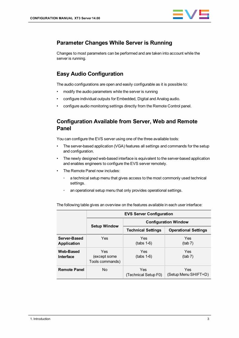
Parameter Changes While Server is Running
Changes tomost parameters can be performed and are taken into account while theserver is running.
Easy Audio Configuration
The audio configurations are open and easily configurable as it is possible to:
• modify the audio parameters while the server is running
• configure individual outputs for Embedded, Digital and Analog audio.
• configure audiomonitoring settings directly from the Remote Control panel.
Configuration Available from Server, Web and RemotePanel
You can configure the EVS server using one of the three available tools:
• The server-based application (VGA) features all settings and commands for the setupand configuration.
• The newly designed web-based interface is equivalent to the server-based applicationand enables engineers to configure the EVS server remotely.
• The Remote Panel now includes:
◦ a technical setupmenu that gives access to themost commonly used technicalsettings.
◦ an operational setupmenu that only provides operational settings.
The following table gives an overview on the features available in each user interface:
EVS Server Configuration
Setup WindowConfiguration Window
Technical Settings Operational Settings
Server-BasedApplication
Yes Yes(tabs 1-6)
Yes(tab 7)
Web-BasedInterface
Yes(except some
Tools commands)
Yes(tabs 1-6)
Yes(tab 7)
Remote Panel No Yes(Technical Setup F0)
Yes(SetupMenu SHIFT+D)
CONFIGURATION MANUAL XT3 Server 14.00
1. Introduction 3
1.2. Introduction to the Manual
Documented User Interfaces
The Server Configurationmanual deals with all user interfaces used to configureMulticam: server-based application, web-based interface, and Remote Panel.
• On the one hand, the information on navigability and editing commands, specific to theuser interface, is described in clearly separated sections.
• On the other hand, the reference information on and the description of configurationparameters are described in common sections valid for all user interfaces. A clearoverview shows whether and where the parameters are available in each userinterface.
NoteThe web-base interface has undergone small cosmetic changes. Thescreenshots have not yet been updated in the configurationmanual.
Configuration Manual Structure
The Server Configurationmanual is organized in two sections:
• A section dedicated to theMulticam Setup window that mainly features:
◦ the configurations lines and their management
◦ the functions related to server administration andmaintenance.
• A section dedicated to theMulticam Configuration window, organized in seven tabs,which describes all server configuration parameters that can be defined for eachconfiguration line. The section includes:
◦ the parameter description itself
◦ other server-related information needed for the configuration
1.3. Starting the EVS Server
Introduction
When switching on the EVS server, the first step is the PC boot sequence, followed bythe boot of the video I/O boards, and finally theMulticam Setup application is started.
4 1. Introduction
EVSBroadcast Equipment SA Issue 14.00.A - June 2015
When Starting the EVS Server for the First Time
Before you first use your EVS server, you need to perform the following tasks:
• Define the configuration lines your EVS server should run.
For more information, see section "Configuration Lines" on page 11.
• Define the configuration parameters for each configuration line you will need.
In this step, you will define, among others, the channel configuration for the selectedconfiguration line, as well as audio and video parameters for the EVS server.
For more information, see section "Multicam Configuration" on page 118.
When Starting the EVS Server After Initial Configuration
After the initial configuration, you will select a configuration line and press ENTER to runthe server in this configuration. See section "Launching a Configuration" on page 12. Assoon as the EVS server is launched in a configuration, it starts the loop recording process.
1.4. Accessing the Web-Based Interface
Prerequisite
When the EVS server is started, you can access the web-based interface of theMulticamSetup application fo r that EVS server from any computer on the same network range asthe EVS server. You can use any browser to open the web-based interface.
Procedure
To be able to open the web-based interface in a browser, you need to know the IP addressof the PC LAN of the EVS server. See section "Setting the Server LAN PC Address" onpage 26 for more information.
In your browser, enter the following URL: http://xxx.xxx.xxx.xxx/cfgweb/ where thecrosses correspond to the PC LAN IP address of the EVS server you want to access.
CONFIGURATION MANUAL XT3 Server 14.00
1. Introduction 5
2. Multicam Setup
2.1. Overview of User Interfaces
2.1.1. Overview of the Setup Areas
General Description
TheMulticam Setup window is the window that opens first when theMulticam Setupapplication is launched. It is displayed when the EVS server is started but does not run agiven configuration yet.
TheMulticam Setup window allows users to:
• view andmanage the various configuration lines.
• perform some administration andmaintenance tasks on the EVS server.
• view summary information on the EVS server and the selected configuration line.
This is available in both server-based and web-basedMulticam Setup applications.
Both user interfaces include the same features, except that the Tools menu offers fewercommands in the web-based user interface.
6 2. MulticamSetup
EVSBroadcast Equipment SA Issue 14.00.A - June 2015
User Interfaces
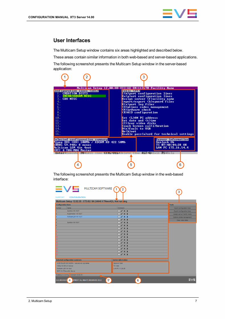
TheMulticam Setup window contains six areas highlighted and described below.
These areas contain similar information in both web-based and server-based applications.
The following screenshot presents theMulticam Setup window in the server-basedapplication:
The following screenshot presents theMulticam Setup window in the web-basedinterface:
CONFIGURATION MANUAL XT3 Server 14.00
2. MulticamSetup 7
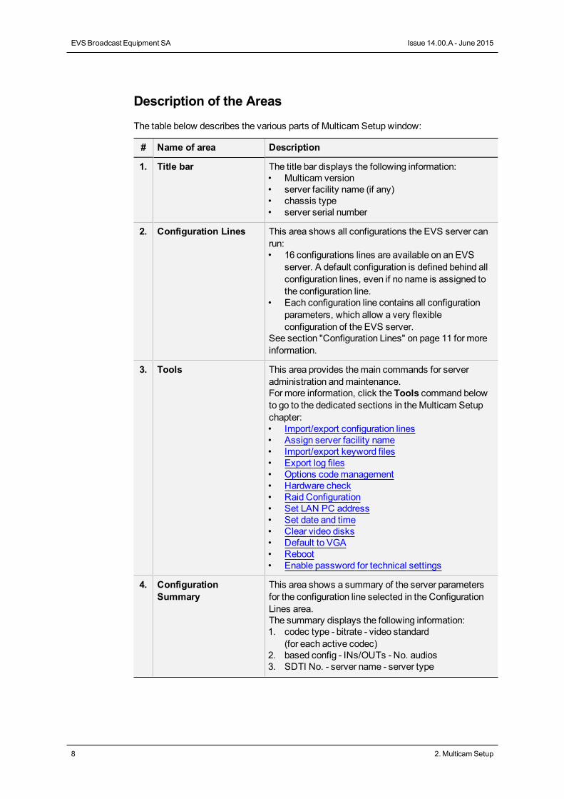
Description of the Areas
The table below describes the various parts of Multicam Setup window:
# Name of area Description
1. Title bar The title bar displays the following information:• Multicam version• server facility name (if any)• chassis type• server serial number
2. Configuration Lines This area shows all configurations the EVS server canrun:• 16 configurations lines are available on an EVS
server. A default configuration is defined behind allconfiguration lines, even if no name is assigned tothe configuration line.
• Each configuration line contains all configurationparameters, which allow a very flexibleconfiguration of the EVS server.
See section "Configuration Lines" on page 11 for moreinformation.
3. Tools This area provides themain commands for serveradministration andmaintenance.For more information, click the Tools command belowto go to the dedicated sections in theMulticam Setupchapter:• Import/export configuration lines• Assign server facility name• Import/export keyword files• Export log files• Options codemanagement• Hardware check• Raid Configuration• Set LAN PC address• Set date and time• Clear video disks• Default to VGA• Reboot• Enable password for technical settings
4. ConfigurationSummary
This area shows a summary of the server parametersfor the configuration line selected in the ConfigurationLines area.The summary displays the following information:1. codec type - bitrate - video standard
(for each active codec)2. based config - INs/OUTs - No. audios3. SDTI No. - server name - server type
8 2. MulticamSetup
EVSBroadcast Equipment SA Issue 14.00.A - June 2015
# Name of area Description
5. Task bar The Task bar (Server-based application) displayscommands for themain actions in the window.See section "Navigability and Commands" on page 9for more information.
5'. Status bar The Status bar (web-based interface) displays:• theMulticam Setup application status• the date and time of the last refresh• theRefresh button
6. Server Information This area displays the following information on the EVSserver:• genlock status (OK or bad)• timecode and timecode status (OK or bad)• IP address of the LAN PC
2.1.2. Navigability and Commands
In the Server-Based Application
General Navigability
The following table presents the general commands to navigate in theMulticam Setupwindow:
Command description Command key
Moving the cursor to the first item of the Tools menu F9
Moving the cursor to the first configuration line ESC
Moving down in the list of editable items(configuration lines and Tools commands)
TAB
Moving up in the list of editable items SHIFT+TAB
Displaying a Help window that gives a summary ofthe commands
F1
CONFIGURATION MANUAL XT3 Server 14.00
2. MulticamSetup 9
Configuration Lines
In the Configuration Lines area, a configuration line is highlighted when it is selected.
Themain commands for configuration linemanagement are presented below:
Command description Command key
Moving up in the list of configuration lines UP ARROW
Moving down in the list of configuration lines DOWN ARROW
Starting the server with a given configuration line ENTER on selected line.
Entering the Configuration window to edit the settingsrelated to a selected line
F8
Renaming a configuration line CTRL + F1
Deleting a configuration line CTRL + DELETE
See section "Configuration Lines" on page 11 for more commands on configuration lines.
Tools Menu
Command description Command key
Selecting a tool command Pressing the shortcut key(between brackets in thecommand name)
Calling a tool command ENTER on the selectedcommand
In the Web-Based Interface
NoteTo be sure that changes have been taken into account in the web-based
interface, refresh regularly the page by clicking theRefresh button in thestatus bar.
10 2. MulticamSetup
EVSBroadcast Equipment SA Issue 14.00.A - June 2015
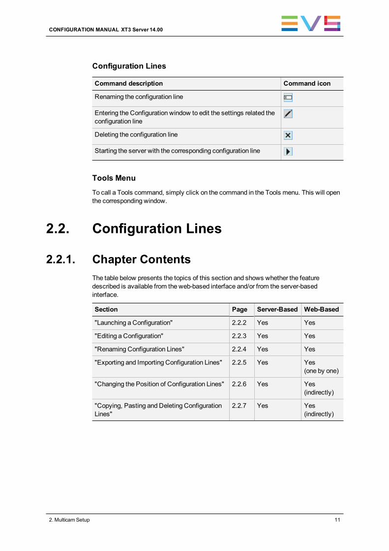
Configuration Lines
Command description Command icon
Renaming the configuration line
Entering the Configuration window to edit the settings related theconfiguration line
Deleting the configuration line
Starting the server with the corresponding configuration line
Tools Menu
To call a Tools command, simply click on the command in the Tools menu. This will openthe corresponding window.
2.2. Configuration Lines
2.2.1. Chapter ContentsThe table below presents the topics of this section and shows whether the featuredescribed is available from the web-based interface and/or from the server-basedinterface.
Section Page Server-Based Web-Based
"Launching a Configuration" 2.2.2 Yes Yes
"Editing a Configuration" 2.2.3 Yes Yes
"Renaming Configuration Lines" 2.2.4 Yes Yes
"Exporting and Importing Configuration Lines" 2.2.5 Yes Yes(one by one)
"Changing the Position of Configuration Lines" 2.2.6 Yes Yes(indirectly)
"Copying, Pasting and Deleting ConfigurationLines"
2.2.7 Yes Yes(indirectly)
CONFIGURATION MANUAL XT3 Server 14.00
2. MulticamSetup 11
2.2.2. Launching a Configuration
Introduction
When the EVS server has initialized, theMulticam Setup window stays open, by default,until the operator selects the requested configuration line and launches it.
Multicam can encode the video signal simultaneously in several essences, and grant aseamless access to the videomaterial in all active essences. Thematerial ingested on anEVS server must therefore, as much as possible, be and remain available on this server inall active essences. For this reason, some restrictions or checks are applied when youlaunch a configuration.
Compatible Multi-Essence Configurations
On the same SDTI network, it is not allowed to have:
• EVS servers with mixedmulti-essence configurations;
or
• a combination of EVS servers supporting and not supportingmulti-essenceconfigurations.
In such situations, you will get the followingmessage when you try to launch aconfiguration on the EVS server: "Incompatible multi-codec configurationon the network".
You have the option to:
• come back to theMulticam Setup window to select a configuration compatible withthe other EVS servers;
• work in standalonemode. This mode will prevent you from browsing the content ofother EVS servers and from transferring content to other EVS servers.
Change of Multi-Essence Configuration
Tomake sure the videomaterial is available in the required essences on the EVS server,you need to perform a clear clip before launching a configuration in the following situations:
• after upgrading fromMulticam 11.XX toMulticam 12.XX.
• in specific changes from one to another multi-essence configuration
See section "Clearing Video Disks" on page 42 for detailed information on when a clearclip is required.
12 2. MulticamSetup
EVSBroadcast Equipment SA Issue 14.00.A - June 2015
How to Manually Launch a Configuration
In the Server-Based Application
To start a configuration in the server-based application, proceed as follows:
1. Press theUP ARROW orDOWN ARROW key to respectively move up and down inthe list of configuration lines until the requested line is highlighted.
2. Press ENTER to run the configuration line on the EVS server.
In the Web-Based Interface
To start a configuration in the web-based interface, click the Launch icon next to theconfiguration line you want to launch.
Automatic Launch
From the server-based application, it is possible to set the server so that the last usedconfiguration line is automatically launched when theMulticam Setup window has stayedopen for five seconds.
To activate the automatic launch, press F7 on the requested configuration line in theMulticam Setupmenu before launching this configuration. This configuration line is thenhighlighted in black (no longer in green) to indicate the automatic launch is active. The lastused configuration line will then be launched automatically after a five seconds' delay thenext time the EVS server will be restarted.
If you want to change the configuration line to be launched, you need to rapidly hit a key onthe keyboard connected to the EVS server within five seconds after theMulticam Setupwindow has been displayed. Then, theMulticam Setup window will stay open and let youselect another configuration.
2.2.3. Editing a Configuration
How to Edit a Configuration
Introduction
When the operator hits a key on the keyboard connected to the EVS server (within fiveseconds if the automatic launch of a configuration is active), theMulticam Setup windowstays open, and the operator can select and enter the selected configuration to edit it.
16 configurations lines are available on an EVS server. A default configuration is definedbehind all configuration lines, even if no name is assigned to the configuration line.
Each configuration line contains all configuration parameters, which allow a very flexibleconfiguration of the EVS server.
CONFIGURATION MANUAL XT3 Server 14.00
2. MulticamSetup 13
In the Server-Based Application
To edit a configuration line in the server-based application, proceed as follows:
1. Press theUP ARROW orDOWN ARROW key to respectively move up and down inthe list of configuration lines until the requested line is highlighted.
2. Press F8.
The Configuration window opens. See section "Multicam Configuration" on page 118to edit the configuration parameters.
3. When the configuration is defined for a given line, press ALT+A in the Configurationwindow to validate the changes
4. Press ESC to come back to the Setup window.
In the Web-Based Interface
To edit a configuration line in the web-based interface, proceed as follows:
1. Click theEdit icon for the configuration line you want to configure.
The Configuration window opens. See section "Multicam Configuration" on page 118to edit the configuration parameters.
2. When the configuration is defined for the given line, click Apply to validate, and thenQuit to come back to the Setup window.
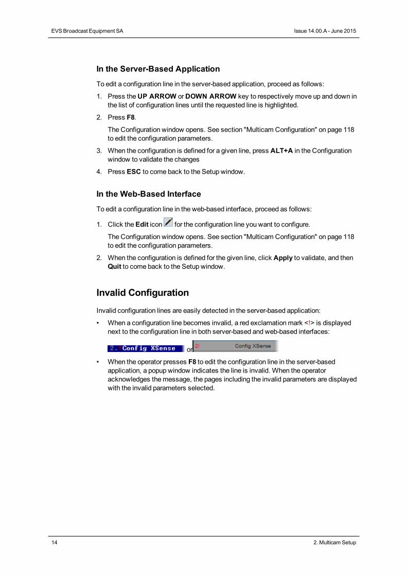
Invalid Configuration
Invalid configuration lines are easily detected in the server-based application:
• When a configuration line becomes invalid, a red exclamationmark <!> is displayednext to the configuration line in both server-based and web-based interfaces:
or
• When the operator presses F8 to edit the configuration line in the server-basedapplication, a popup window indicates the line is invalid. When the operatoracknowledges themessage, the pages including the invalid parameters are displayedwith the invalid parameters selected.
14 2. MulticamSetup
EVSBroadcast Equipment SA Issue 14.00.A - June 2015
2.2.4. Renaming Configuration Lines
Introduction
When the EVS server is delivered, default names are assigned to the configuration lines.You can change them as explained below.
In the Server-Based Application
To rename the configuration line in the server-based application, proceed as follows:
1. Press theUP ARROW orDOWN ARROW key to respectively move up and down inthe list of configuration lines until the requested line is highlighted.
2. Press CTRL+F1.
The line if highlighted in pink and the cursor blinks on the first character.
3. Type the new name for the configuration line taking the following into account:
◦ The space bar allows you to delete the selected character.
◦ The LEFT ARROW andRIGHT ARROW keys allow you tomove the cursorposition on the line.
4. Press ENTER to validate the new name.
The new name is assigned to the configuration line and reflected in all user interfaces.
In the Web-Based Interface
To rename the configuration line in the web-based interface, proceed as follows:
1. Click theRename button next to the configuration line you want to rename.
2. In theRename dialog box, type the new configuration name.
3. Click OK.
The new name is assigned to the configuration line and reflected in all user interfaces.
CONFIGURATION MANUAL XT3 Server 14.00
2. MulticamSetup 15
2.2.5. Exporting and Importing ConfigurationLines
How to Export Configuration Lines
NoteThe screenshots in this section features configuration names which areexamples, andmay not reflect configurations supported on your EVS server.
In the Server-Based Application
To export configuration lines from an EVS server in the server-based application, proceedas follows:
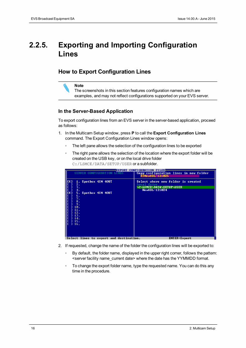
1. In theMulticam Setup window, press P to call theExport Configuration Linescommand. The Export Configuration Lines window opens:
◦ The left pane allows the selection of the configuration lines to be exported
◦ The right pane allows the selection of the location where the export folder will becreated on the USB key, or on the local drive folderC:/LSMCE/DATA/SETUP/USER or a subfolder.
2. If requested, change the name of the folder the configuration lines will be exported to:
◦ By default, the folder name, displayed in the upper right corner, follows the pattern:<server facility name_current date> where the date has the YYMMDD format.
◦ To change the export folder name, type the requested name. You can do this anytime in the procedure.
16 2. MulticamSetup
EVSBroadcast Equipment SA Issue 14.00.A - June 2015
3. If requested, change the selection of configuration lines selected for export on the leftpane:
◦ By default, a cross is displayed in front of all configuration lines, whichmeansthey are all selected for export.
◦ To deselect a line, use theUP ARROW orDOWN ARROW key to highlight therequested line, and press SPACEBAR. The cross is removed, and thedeselected lines turn light gray.
4. Press TAB to shift the focus to the right pane.
5. If requested, change the location where the export folder will be created:
◦ By default, the export folder is created on the USB key root or on the local drivefolder the local drive folder C:/LSMCE/DATA/SETUP/USER.
◦ To change the folder where the export folder will be created, highlight therequested folder. The last highlighted folder will be considered as the requestedlocation.
6. To start the export process, press ENTER.
7. When the selected lines are exported (as a .lin file), a message opens to confirm theexport. Click OKto acknowledge themessage.
In the Web-Based Interface
NoteIn the web-based interface, it is only possible to export configuration lines one byone.
To export configuration lines from an EVS server in the web-based interface, proceed asfollows:
1. From theMulticam Setup window, click Export configuration lines in the Toolsmenu.
The Export configuration lines window opens:
CONFIGURATION MANUAL XT3 Server 14.00
2. MulticamSetup 17
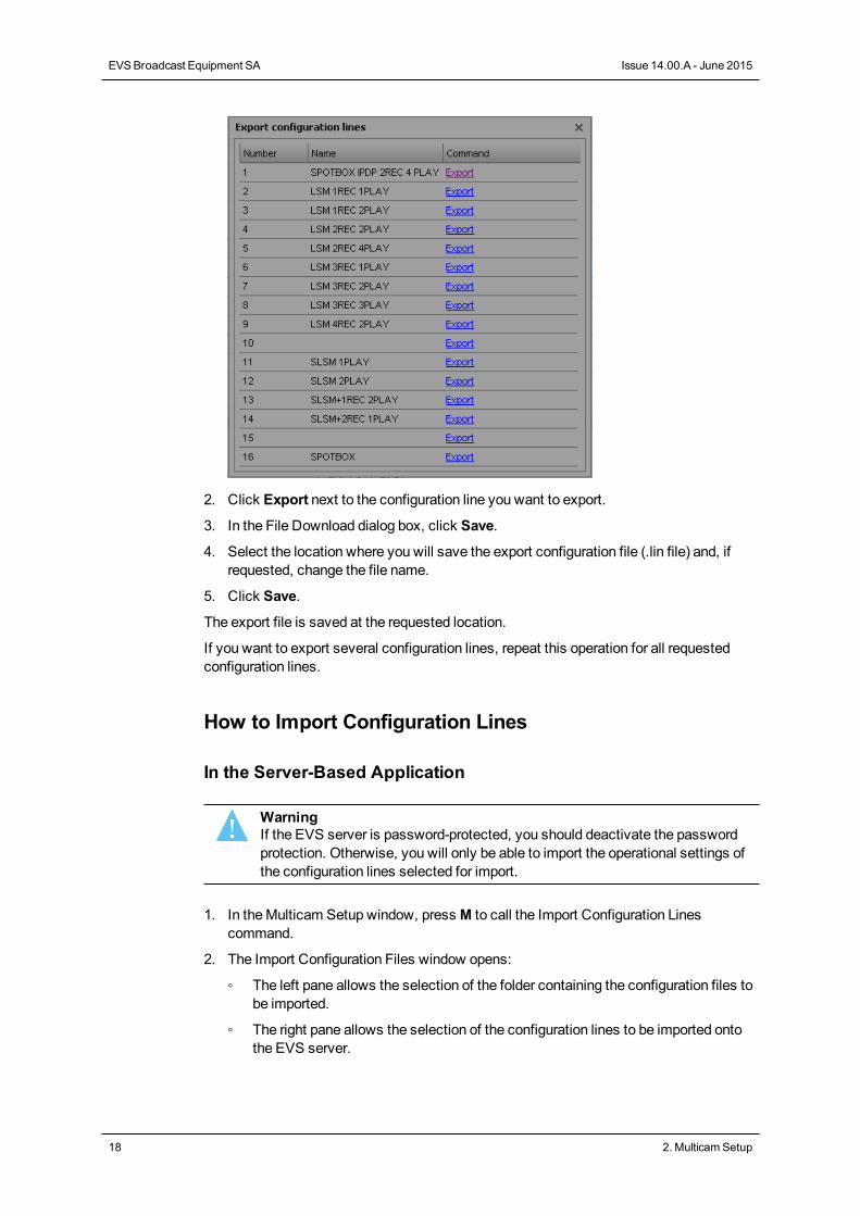
2. Click Export next to the configuration line you want to export.
3. In the File Download dialog box, click Save.
4. Select the location where you will save the export configuration file (.lin file) and, ifrequested, change the file name.
5. Click Save.
The export file is saved at the requested location.
If you want to export several configuration lines, repeat this operation for all requestedconfiguration lines.
How to Import Configuration Lines
In the Server-Based Application
WarningIf the EVS server is password-protected, you should deactivate the passwordprotection. Otherwise, you will only be able to import the operational settings ofthe configuration lines selected for import.
1. In theMulticam Setup window, press M to call the Import Configuration Linescommand.
2. The Import Configuration Files window opens:
◦ The left pane allows the selection of the folder containing the configuration files tobe imported.
◦ The right pane allows the selection of the configuration lines to be imported ontothe EVS server.
18 2. MulticamSetup
EVSBroadcast Equipment SA Issue 14.00.A - June 2015
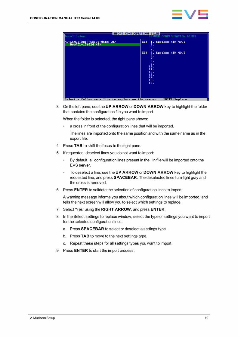
3. On the left pane, use theUP ARROW orDOWN ARROW key to highlight the folderthat contains the configuration file you want to import.
When the folder is selected, the right pane shows:
◦ a cross in front of the configuration lines that will be imported.
The lines are imported onto the same position and with the same name as in theexport file.
4. Press TAB to shift the focus to the right pane.
5. If requested, deselect lines you do not want to import:
◦ By default, all configuration lines present in the .lin file will be imported onto theEVS server.
◦ To deselect a line, use theUP ARROW orDOWN ARROW key to highlight therequested line, and press SPACEBAR. The deselected lines turn light gray andthe cross is removed.
6. Press ENTER to validate the selection of configuration lines to import.
A warningmessage informs you about which configuration lines will be imported, andtells the next screen will allow you to select which settings to replace.
7. Select 'Yes' using theRIGHT ARROW, and press ENTER.
8. In the Select settings to replace window, select the type of settings you want to importfor the selected configuration lines:
a. Press SPACEBAR to select or deselect a settings type.
b. Press TAB to move to the next settings type.
c. Repeat these steps for all settings types you want to import.
9. Press ENTER to start the import process.
CONFIGURATION MANUAL XT3 Server 14.00
2. MulticamSetup 19
In the Web-Based Interface
NoteIn the web-based interface, it is only possible to import configuration lines one byone.
To import configuration lines onto an EVS server in the web-based interface, proceed asfollows:
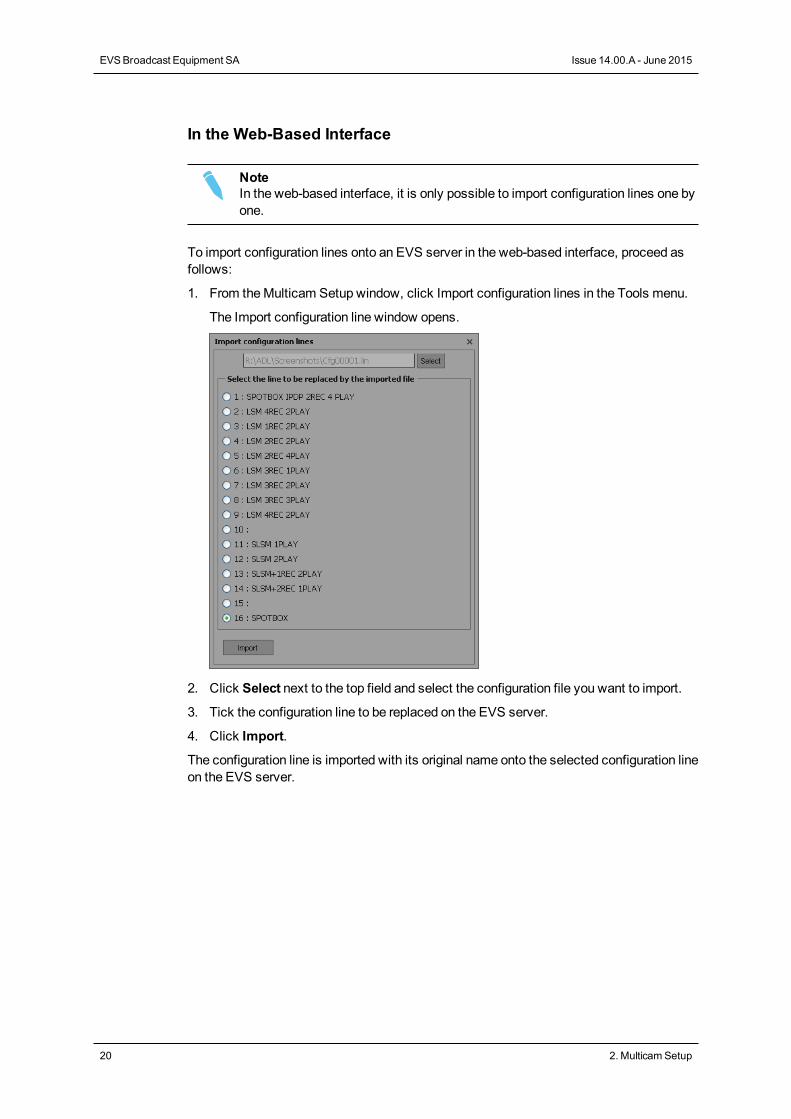
1. From theMulticam Setup window, click Import configuration lines in the Tools menu.
The Import configuration line window opens.
2. Click Select next to the top field and select the configuration file you want to import.
3. Tick the configuration line to be replaced on the EVS server.
4. Click Import.
The configuration line is imported with its original name onto the selected configuration lineon the EVS server.
20 2. MulticamSetup
EVSBroadcast Equipment SA Issue 14.00.A - June 2015
2.2.6. Changing the Position of ConfigurationLines
In the Server-Based Application
Tomove a configuration line up in the list in the server-based application, proceed asfollows:
1. Press theUP ARROW orDOWN ARROW key to respectively move up and down inthe list of configuration lines until the requested line is highlighted.
2. Do one of the following:
◦ Tomove the selected line up, press CTRL + UP ARROW.
◦ Tomove the selected line down, press CTRL + DOWN ARROW.
In the Web-Based Interface
The feature tomove configuration lines up and down in the list of configuration lines is notavailable as such in the web-based interface.
You can however use the import and export feature to change the position of lines in thelist of configuration lines.
2.2.7. Copying, Pasting and DeletingConfiguration Lines
How to Copy/Paste Configuration Lines
In the Server-Based Application
WarningNote that copying a line onto another position will erase the configuration on theselected position.
To copy and paste a configuration line in the server-based application, proceed as follows:
1. Press theUP ARROW orDOWN ARROW key to respectively move up and down inthe list of configuration lines until the requested line is highlighted.
2. Press CTRL+C to copy the line to the clipboard.
3. With theUP ARROW andDOWN ARROW keys, move to the position where youwant to copy the line.
4. Press CTRL + V to paste the line to the selected position.
5. Press ENTER to confirm that you agree to replace the former configuration line by theone copied on the selected position.
CONFIGURATION MANUAL XT3 Server 14.00
2. MulticamSetup 21
In the Web-Based Interface
The feature to copy and paste configuration lines is not available as such in the web-basedinterface.
You can however use the import and export feature to change the position of lines in thelist of configuration lines.
How to Delete Configuration Lines
WarningWhen you delete a configuration line, the line will automatically be deleted,without prior warningmessage.
In the Server-Based Application
To delete a configuration line in the server-based application, proceed as follows:
1. Press theUP ARROW orDOWN ARROW key to respectively move up and down inthe list of configuration lines until the requested line is highlighted.
2. Press CTRL+DEL to delete the line.
The line is directly deleted.
In the Web-Based Interface
To delete a configuration line in the web-based interface, click theDelete icon next tothe configuration line you want to delete.
The configuration line is directly deleted.
22 2. MulticamSetup
EVSBroadcast Equipment SA Issue 14.00.A - June 2015
2.3. Server Parameters
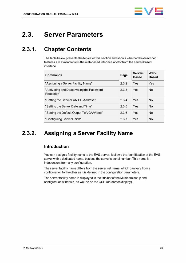
2.3.1. Chapter ContentsThe table below presents the topics of this section and shows whether the describedfeatures are available from the web-based interface and/or from the server-basedinterface.
Commands Page Server-Based
Web-Based
"Assigning a Server Facility Name" 2.3.2 Yes Yes
"Activating and Deactivating the PasswordProtection"
2.3.3 Yes No
"Setting the Server LAN PC Address" 2.3.4 Yes No
"Setting the Server Date and Time" 2.3.5 Yes No
"Setting the Default Output To VGA/Video" 2.3.6 Yes No
"Configuring Server Raids" 2.3.7 Yes No
2.3.2. Assigning a Server Facility Name
Introduction
You can assign a facility name to the EVS server. It allows the identification of the EVSserver with a dedicated name, besides the server's serial number. This name isindependent from any configuration.
The server facility name differs from the server net name, which can vary from aconfiguration to the other as it is defined in the configuration parameters.
The server facility name is displayed in the title bar of theMulticam setup andconfiguration windows, as well as on the OSD (on-screen display).
CONFIGURATION MANUAL XT3 Server 14.00
2. MulticamSetup 23
In the Server-Based Application
To assign a server facility name in the server-based application, proceed as follows:
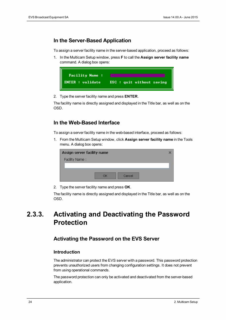
1. In theMulticam Setup window, press F to call theAssign server facility namecommand. A dialog box opens:
2. Type the server facility name and press ENTER.
The facility name is directly assigned and displayed in the Title bar, as well as on theOSD.
In the Web-Based Interface
To assign a server facility name in the web-based interface, proceed as follows:
1. From theMulticam Setup window, click Assign server facility name in the Toolsmenu. A dialog box opens:
2. Type the server facility name and press OK.
The facility name is directly assigned and displayed in the Title bar, as well as on theOSD.
2.3.3. Activating and Deactivating the PasswordProtection
Activating the Password on the EVS Server
Introduction
The administrator can protect the EVS server with a password. This password protectionprevents unauthorized users from changing configuration settings. It does not preventfrom using operational commands.
The password protection can only be activated and deactivated from the server-basedapplication.
24 2. MulticamSetup
EVSBroadcast Equipment SA Issue 14.00.A - June 2015
The password protection has the following impact on the various user interfaces:
• The password is required to apply changes to configuration parameters in the server-based application and in the web-based interface.
• On the Remote Panel, the Technical Setupmenu is not available.
How to Activate the Password on the EVS Server
To activate a password on the EVS server, proceed as follows:
1. In theMulticam Setup window, pressW to call the Enable password command. Awarningmessage opens.
2. Read the warningmessage carefully. Press theRIGHT ARROW key to select 'Yes'and press ENTER to activate the password protection.
The password protection is directly active in all user interfaces, for all configurationparameters on all configuration lines.
Enabling Changes to Configuration Parameters
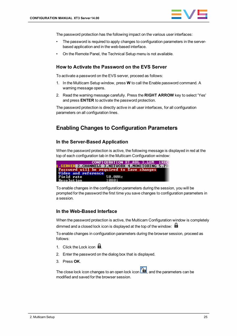
In the Server-Based Application
When the password protection is active, the followingmessage is displayed in red at thetop of each configuration tab in theMulticam Configuration window:
To enable changes in the configuration parameters during the session, you will beprompted for the password the first time you save changes to configuration parameters ina session.
In the Web-Based Interface
When the password protection is active, theMulticam Configuration window is completelydimmed and a closed lock icon is displayed at the top of the window:
To enable changes in configuration parameters during the browser session, proceed asfollows:
1. Click the Lock icon .
2. Enter the password on the dialog box that is displayed.
3. Press OK.
The close lock icon changes to an open lock icon , and the parameters can bemodified and saved for the browser session.
CONFIGURATION MANUAL XT3 Server 14.00
2. MulticamSetup 25
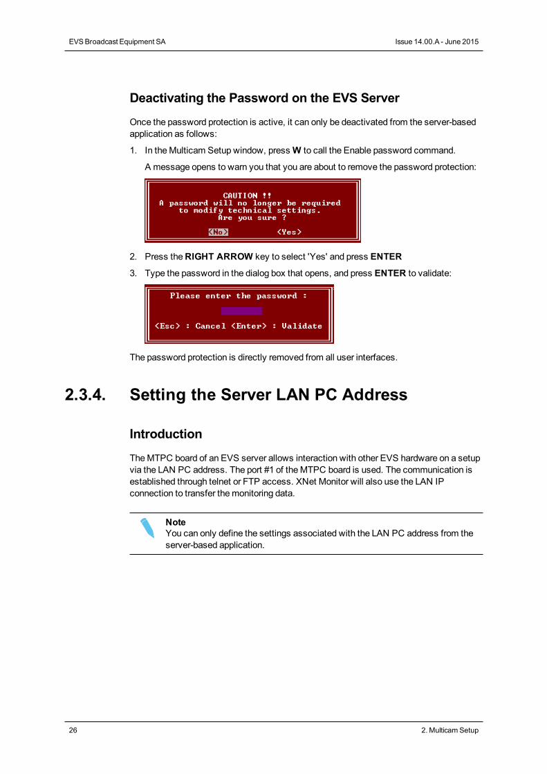
Deactivating the Password on the EVS Server
Once the password protection is active, it can only be deactivated from the server-basedapplication as follows:
1. In theMulticam Setup window, pressW to call the Enable password command.
A message opens to warn you that you are about to remove the password protection:
2. Press theRIGHT ARROW key to select 'Yes' and press ENTER
3. Type the password in the dialog box that opens, and press ENTER to validate:
The password protection is directly removed from all user interfaces.
2.3.4. Setting the Server LAN PC Address
Introduction
TheMTPC board of an EVS server allows interaction with other EVS hardware on a setupvia the LAN PC address. The port #1 of theMTPC board is used. The communication isestablished through telnet or FTP access. XNet Monitor will also use the LAN IPconnection to transfer themonitoring data.
NoteYou can only define the settings associated with the LAN PC address from theserver-based application.
26 2. MulticamSetup
EVSBroadcast Equipment SA Issue 14.00.A - June 2015
Settings
TheMTPC board connection settings are described in the table below:
Setting Description
IP Address Specifies the IP address to connect to the port #1 of theMTPC board onthe server. The IP addresses 0.0.0.0 and 255.255.255.255 are notallowed.
Subnet Mask Specifies the range of logical addresses within the address spaceassigned to theMTPC board connection.
DefaultGateway
Specifies the IP address of the router on the network that theMTPCboard can use as an access point to external networks.
How to Set the LAN PC
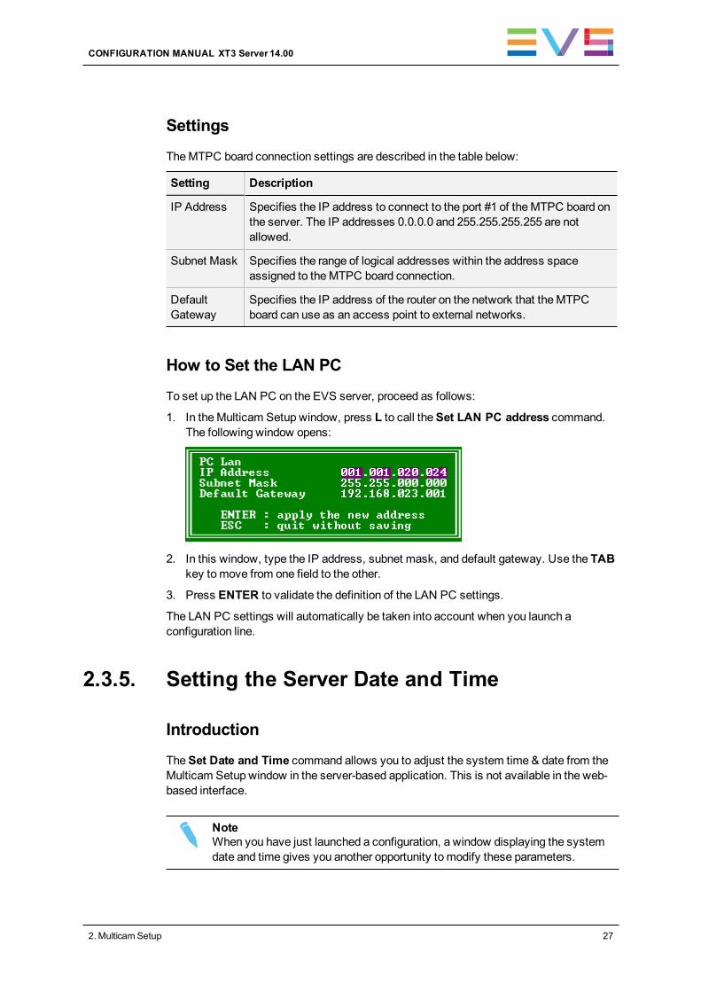
To set up the LAN PC on the EVS server, proceed as follows:
1. In theMulticam Setup window, press L to call theSet LAN PC address command.The following window opens:
2. In this window, type the IP address, subnet mask, and default gateway. Use the TABkey tomove from one field to the other.
3. Press ENTER to validate the definition of the LAN PC settings.
The LAN PC settings will automatically be taken into account when you launch aconfiguration line.
2.3.5. Setting the Server Date and Time
Introduction
TheSet Date and Time command allows you to adjust the system time & date from theMulticam Setup window in the server-based application. This is not available in the web-based interface.
NoteWhen you have just launched a configuration, a window displaying the systemdate and time gives you another opportunity to modify these parameters.
CONFIGURATION MANUAL XT3 Server 14.00
2. MulticamSetup 27
Supported Formats
The supported date format is DD-MM-YYYY, as shown in the example below:
• 15-03-2011 for March 15, 2011
The supported time format is hh:mm:ss, as shown in the example below
• 22:58:00 for 22 h 58min 00 sec (24-hour display)
A warningmessage will inform you if the format you try to use is not valid.
How to Set the System Date and Time
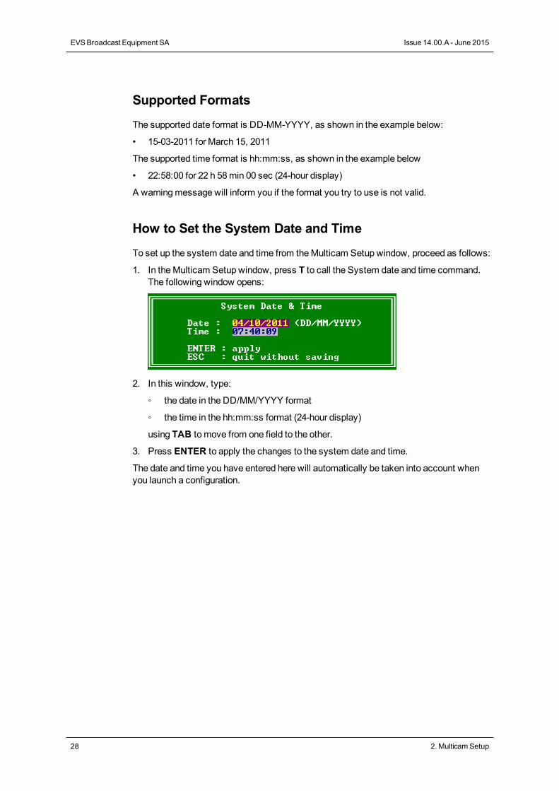
To set up the system date and time from theMulticam Setup window, proceed as follows:
1. In theMulticam Setup window, press T to call the System date and time command.The following window opens:
2. In this window, type:
◦ the date in the DD/MM/YYYY format
◦ the time in the hh:mm:ss format (24-hour display)
using TAB to move from one field to the other.
3. Press ENTER to apply the changes to the system date and time.
The date and time you have entered here will automatically be taken into account whenyou launch a configuration.
28 2. MulticamSetup
EVSBroadcast Equipment SA Issue 14.00.A - June 2015
2.3.6. Setting the Default Output To VGA/Video
Introduction
Between the PC boot and the I/O boot, the video driver is loaded. TheDefault Output toVGA/Video command allows you to switch the video display from and to one of thefollowingmodes:
• VGA mode
• B&W videomode. This mode sends a video CVBS output on the VGA connector,which allows the VGA screen to be displayed on a standard composite videomonitorusing the VGA <==> BNC adapter provided with the unit.
NoteWhen a configuration has been launched, you can still switch from onemode tothe other withALT + BACKSPACE.
How to Change the Default Output
PressingE allows you to toggle from onemode to the other, and so changing the defaultoutput mode.
The parameter displayed on theMulticam Setup window corresponds to the active value.This means that when the parameter displayed is 'Default to VGA', the activemode is theVGA mode.
2.3.7. Configuring Server Raids
Introduction
When the EVS server is started, the server raids are automatically detected, and builtbased on the default settings described in the 'Default Raid Configuration' section below.
You can view the default raid configuration andmodify it from the Raid Configurationwindow. This window is only available in the server-based application.
NoteOnly hard disk drives from EVS can be used as they are specifically configuredto work with EVS video servers.
CONFIGURATION MANUAL XT3 Server 14.00
2. MulticamSetup 29
Overview on the Raid Configuration Window
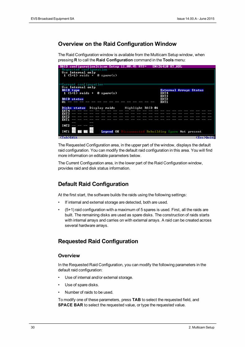
The Raid Configuration window is available from theMulticam Setup window, whenpressingR to call theRaid Configuration command in the Toolsmenu:
The Requested Configuration area, in the upper part of the window, displays the defaultraid configuration. You canmodify the default raid configuration in this area. You will findmore information on editable parameters below.
The Current Configuration area, in the lower part of the Raid Configuration window,provides raid and disk status information.
Default Raid Configuration
At the first start, the software builds the raids using the following settings:
• If internal and external storage are detected, both are used.
• (5+1) raid configuration with amaximum of 5 spares is used. First, all the raids arebuilt. The remaining disks are used as spare disks. The construction of raids startswith internal arrays and carries on with external arrays. A raid can be created acrossseveral hardware arrays.
Requested Raid Configuration
Overview
In the Requested Raid Configuration, you canmodify the following parameters in thedefault raid configuration:
• Use of internal and/or external storage.
• Use of spare disks.
• Number of raids to be used.
Tomodify one of these parameters, press TAB to select the requested field, andSPACE BAR to select the requested value, or type the requested value.
30 2. MulticamSetup
EVSBroadcast Equipment SA Issue 14.00.A - June 2015
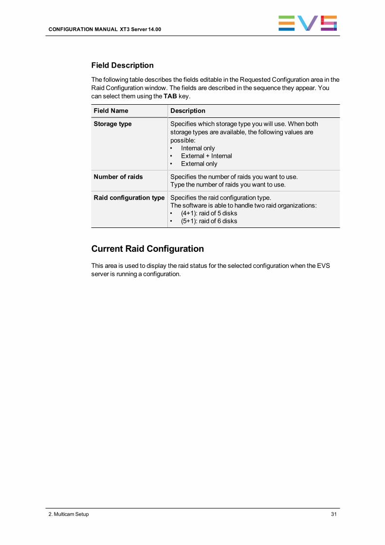
Field Description
The following table describes the fields editable in the Requested Configuration area in theRaid Configuration window. The fields are described in the sequence they appear. Youcan select them using the TAB key.
Field Name Description
Storage type Specifies which storage type you will use. When bothstorage types are available, the following values arepossible:• Internal only• External + Internal• External only
Number of raids Specifies the number of raids you want to use.Type the number of raids you want to use.
Raid configuration type Specifies the raid configuration type.The software is able to handle two raid organizations:• (4+1): raid of 5 disks• (5+1): raid of 6 disks
Current Raid Configuration
This area is used to display the raid status for the selected configuration when the EVSserver is running a configuration.
CONFIGURATION MANUAL XT3 Server 14.00
2. MulticamSetup 31
2.4. Licenses and Maintenance
2.4.1. Overview on Options Codes Management
Introduction
To run a software application and/or specific software options, not only the software itselfis required but also a license key (called 'license code' in Multicam), which is unique forevery option on every system.
This license keys can be temporary, be valid only until a defined deadline fordemonstration purposes, or be permanent with no time limit.
The license keys aremanaged from theOptions codes management window. Thiswindow is available in both the server-based application and the web-based interface.
NoteWhen a temporary license code will expire within the next two weeks or isexpired, the system warns the operator when theMulticam Setup windowopens.
Accessing the Options Codes Management Window
To open theOptions codes management window in the server-based application, press Ofrom theMulticam Setup window.
To open theOption codes management window in the web-based interface, click Optionscode management in the Tools menu from theMulticam Setup window.
32 2. MulticamSetup
EVSBroadcast Equipment SA Issue 14.00.A - June 2015
2.4.2. Options Codes Management Window
In the Server-Based Application
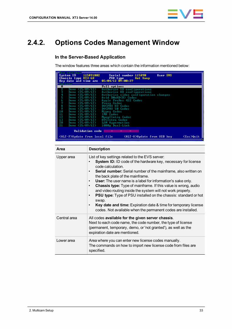
The window features three areas which contain the informationmentioned below:
Area Description
Upper area List of key settings related to the EVS server:• System ID: ID code of the hardware key, necessary for license
code calculation.• Serial number:Serial number of themainframe, also written on
the back plate of themainframe.• User: The user name is a label for information's sake only.• Chassis type: Type of mainframe. If this value is wrong, audio
and video routing inside the system will not work properly.• PSU type: Type of PSU installed on the chassis: standard or hot
swap.• Key date and time:Expiration date & time for temporary license
codes. Not available when the permanent codes are installed.
Central area All codes available for the given server chassis.Next to each code name, the code number, the type of license(permanent, temporary, demo, or 'not granted'), as well as theexpiration date arementioned.
Lower area Area where you can enter new license codes manually.The commands on how to import new license code from files arespecified.
CONFIGURATION MANUAL XT3 Server 14.00
2. MulticamSetup 33
In the Web-Based Interface
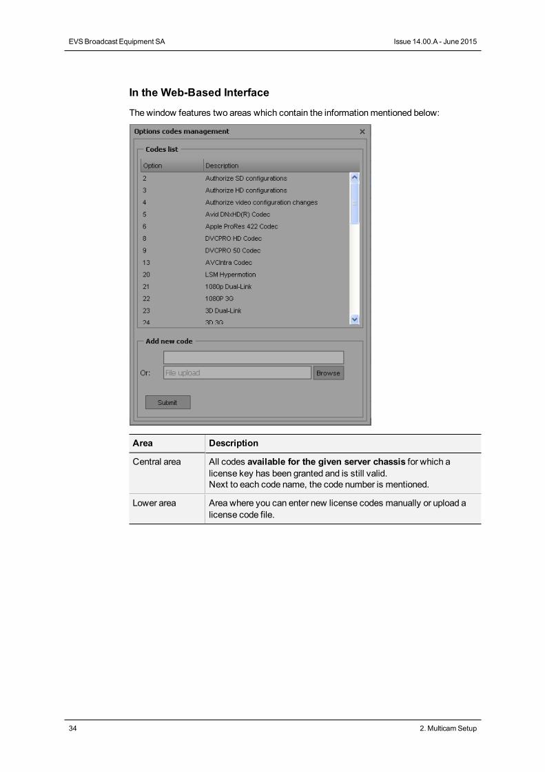
The window features two areas which contain the informationmentioned below:
Area Description
Central area All codes available for the given server chassis for which alicense key has been granted and is still valid.Next to each code name, the code number is mentioned.
Lower area Area where you can enter new license codes manually or upload alicense code file.
34 2. MulticamSetup
EVSBroadcast Equipment SA Issue 14.00.A - June 2015
2.4.3. Entering and Removing License Codes
Introduction
When you request new license codes to activate one or more features, you can receivethe license keys from EVS in the form of:
• a xxxxx.COD file (xxxxx = serial number of the server for which this file has beencalculated). You need to apply this file to the EVS server from theOption codesmanagement window.
• a license code that you can type in the Option codes management window.
Once the license codes have been entered, the corresponding options or features areautomatically active when you launch a configuration, without having to reboot the server.
How to Enter License Codes from a COD File
In the Server-Based Application
To enter a new license code delivered via a COD file, proceed in one of the followingways:
1. Copy the .COD file on a USB key that you connect to the USB port of the EVS server.
2. From theMulticam Setup window, press O to open theOptions codes managementwindow.
3. Press simultaneously ALT+ U keys.
OR
1. Copy manually the .COD file to the C:\ drive of the EVS server.
2. In theMulticam Setupmenu, press O to open theOptions codes managementwindow.
3. Press simultaneously ALT+ F keys.
The license codes will be read from the .COD file and updated into the system. Next to theline corresponding to the code, the license type, and the expiration date, if any, aredisplayed.
CONFIGURATION MANUAL XT3 Server 14.00
2. MulticamSetup 35
In the Web-Based Interface
To enter a new license code delivered via a COD file, proceed as follows:
1. Copy the .COD file onto a drive available from your PC.
2. From theMulticam Setup window, click Options code management in the Toolsmenu to open theOptions codemanagement window.
3. Click theBrowse button, select the .COD file and click Open.
4. Click Submit.
The license codes will be read from the local file and updated into the system.
The lines corresponding to the new codes area added to the code list.
How to Enter License Codes with a Key Number
In the Server-Based Application
To enter a new license code delivered via a key number, proceed as follows:
1. From theMulticam Setup window, press O to open theOptions codes managementwindow.
2. Type the code you have received. It will automatically be typed in the Validation Codefield:
3. Press ENTER.
Next to the line corresponding to the activated codes, the license type and the expirationdate (if any) are displayed.
In the Web-Based Interface
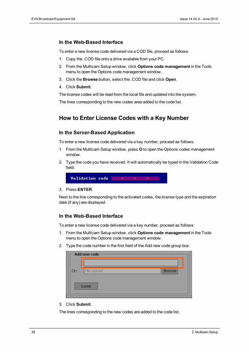
To enter a new license code delivered via a key number, proceed as follows:
1. From theMulticam Setup window, click Options code management in the Toolsmenu to open theOptions codemanagement window.
2. Type the code number in the first field of the Add new code group box:
3. Click Submit.
The lines corresponding to the new codes are added to the code list.
36 2. MulticamSetup
EVSBroadcast Equipment SA Issue 14.00.A - June 2015
How to Remove a License Code
You can remove a license code from the server-based application. Proceed as follows:
1. Press theUP ARROW andDOWN ARROW keys tomove inside the options list andselect the option to be removed.
2. When the option is selected (highlighted in white), press simultaneously CTRL+DELETE on the keyboard.
3. Confirm the deletion of the option withENTER.
2.5. Server Maintenance
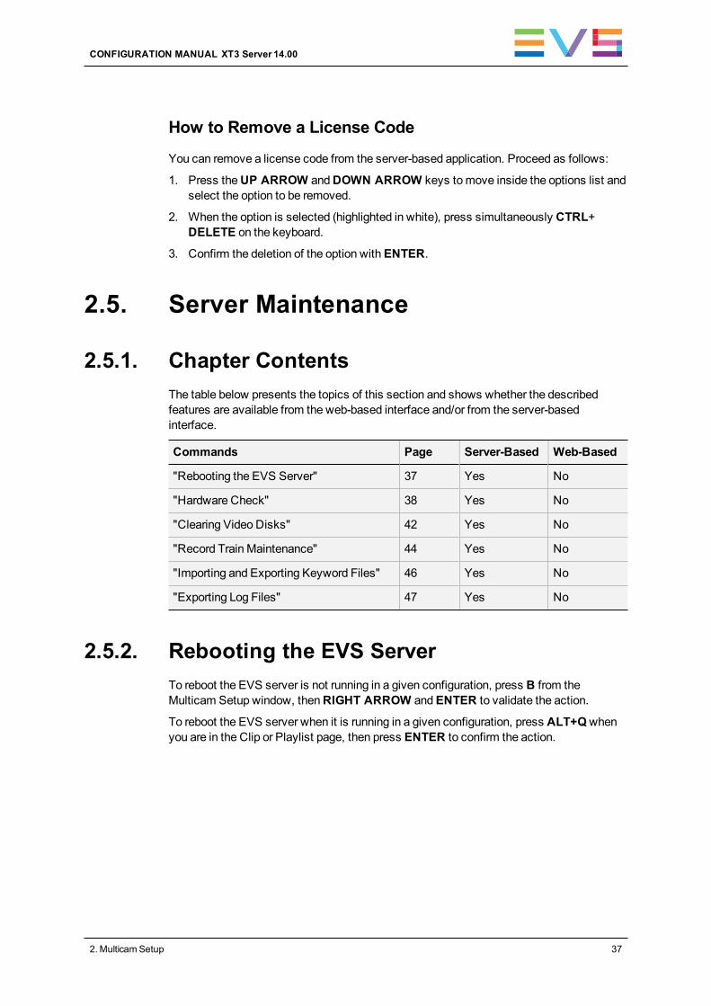
2.5.1. Chapter ContentsThe table below presents the topics of this section and shows whether the describedfeatures are available from the web-based interface and/or from the server-basedinterface.
Commands Page Server-Based Web-Based
"Rebooting the EVS Server" 37 Yes No
"Hardware Check" 38 Yes No
"Clearing Video Disks" 42 Yes No
"Record Train Maintenance" 44 Yes No
"Importing and Exporting Keyword Files" 46 Yes No
"Exporting Log Files" 47 Yes No
2.5.2. Rebooting the EVS ServerTo reboot the EVS server is not running in a given configuration, press B from theMulticam Setup window, thenRIGHT ARROW andENTER to validate the action.
To reboot the EVS server when it is running in a given configuration, press ALT+Qwhenyou are in the Clip or Playlist page, then press ENTER to confirm the action.
CONFIGURATION MANUAL XT3 Server 14.00
2. MulticamSetup 37
2.5.3. Hardware Check
Overview on the Hardware Check
Purpose
During the hardware check, the following actions are performed:
• Retrieving and checking relevant information related to the various boards installed onthe EVS server
• Verifying the validity of the data recorded on the video disk array
The hardware check is only available in the server-based application.
TipHardware check is also used to rebuild the video and audio information afterreplacing a faulty disk.
Process
The hardware check runs the same steps and checks as the server boot process :
1. MTPC check
2. H3X or H3XP check
3. Video Codec check
4. Quad booting
5. GbE download
6. Disk check
7. Data loading
After you have launched the hardware check by pressingH in theMulticam Setupwindow, the system automatically starts the test process.
One after the other, the various steps are displayed in the BOOT.H3X window. The testprocess is completed when the H3X or H3XP board is initialized.
At the end of the hardware check, the hardware revisions information is displayed. Theinformation is logged in the bootwins.log.
38 2. MulticamSetup
EVSBroadcast Equipment SA Issue 14.00.A - June 2015
Disk Errors and Disconnection
Disconnection
When one disk of the video raid array has sustained errors, Multicam automaticallydisconnects that disk and uses the parity disk to rebuild themissing data and provide thevideo and audio data blocks to the application. The operator can thus continue workingnormally and themessage “!Raid” appears on all monitoring outputs.
A message is displayed each time a disk is disconnected:
• if the faulty disk is a spare disk:
"Warning: a spare disk has been disconnected. The system willoperate normally on the remaining disks.
At the next opportunityplease consider replacing the faulty disk. It can be identifiedin the Shift-F5 screen or in the EVS - RAID configuration menu.
[Enter]=Continue"
• if the faulty disk is contained in a RAID:
"Warning: a disk has been disconnected. The system will operatenormally on the remaining disks. At the next opportunity
please consider replacing the faulty disk. It can be identifiedin the Shift-F5 screen or in the EVS - RAID configuration menu.
[Enter]=Continue"
Exit
When exitingMulticam, a warning will appear to remind the operator that one disk wasdisconnected, and invite him to perform a hardware check to repair the video raid. This isdisplayed even if a spare disk is available:
• if the faulty disk is a spare disk:
"Warning: a spare disk has been disconnected. At the nextopportunity please consider replacing the faulty disk. It can
be identified in the Shift-F5 screen or in the EVS - RAIDconfiguration menu. [Enter]=Continue"
• if the faulty disk is contained in a RAID:
"Warning: a disk has been disconnected. At the next opportunityplease consider replacing the faulty disk. It can be identifiedin the Shift-F5 screen or in the EVS - RAID configuration menu.
[Enter]=Continue"
CONFIGURATION MANUAL XT3 Server 14.00
2. MulticamSetup 39
Restarting
If Multicam is restarted without the RAID being rebuilt, a message similar to the followingone, and adapted to the disk type, is displayed during the bootwins:
• if a spare disk is OK:
[ Bad ] SEAGATE ST9300603SS 3SE10H1J 0006 279GB 02 07
• if no spare disk is OK and the RAID is nomore complete:
[ Bad ] SEAGATE ST9300603SS 3SE10H1J 0006 279GB 02 07
WARNING !!! Tray XX is missing 1 disk(s) to be complete
Then when enteringMulticam, another message appears, even if a spare disk is available:
• if the faulty disk is a spare disk:
"Warning: a spare disk has been disconnected. The system willoperate normally on the remaining disks. At the next
opportunity please consider replacing the faulty disk. It canbe identified in the Shift-F5 screen or in the EVS - RAID
configuration menu. [Enter]=Continue"
• if the faulty disk is contained in a RAID:
"Warning: a disk has been disconnected. The system will operatenormally on the remaining disks. At the next opportunity pleaseconsider replacing the faulty disk. It can be identified in the
Shift-F5 screen or in the EVS - RAID configuration menu.[Enter]=Continue"
The operator can press ENTER and operate normally on 4 disks (configuration “4+1”) or on5 disks (configuration “5+1”) or exit the software and return toMulticam Setup window torun a hardware check.
Retrieving LogsIf you suspect that the drive disconnection in operation was not due to a severe diskfailure, but perhaps to the server being too prompt to disconnect a drive, youmust run ahardware check immediately after ending the session during which the disk wasdisconnected.
Don’t rebuild the RAID, but press simultaneously theALT+L keys to generate the log fileC:\LSMCE\DATA\LOG\SCSI.LOG, and send this file to EVS for detailed analysis. Notethat this procedure is only valid if the drive is disconnected during operation, not for a drivebeing disconnected when booting the system.
40 2. MulticamSetup
EVSBroadcast Equipment SA Issue 14.00.A - June 2015
Rebuild Process
Introduction
The XT3 server is capable of performing a rebuild process of the RAID. This process canhappen either while theMulticam application is not running (offline process – rebuild isfaster) or while theMulticam application is running (online process – rebuild is slower).
Disconnection Process
As explained in the section "Disk Errors and Disconnection" on page 39, the software willdisconnect a disk that does not behave as expected.
Two options are available for the operator:
• Replace the disconnected disk and restart the server
◦ Start theMulticam application. The rebuild process will start automatically.
◦ Start a hardware check from the EVS menu and launch the rebuild. The processstarts offline. The operator can wait for the rebuild to be completed or cancel it(that is to say postpone it) and start theMulticam application, in which case therebuild carries on in onlinemode.
• The operator can also force the disk to be reconnected by starting the rebuild processin the hardware check. The process starts offline. The operator can wait for the rebuildto be completed or cancel it and start theMulticam application, in which case therebuild carries on in onlinemode.
NoteIf errors are detected during the rebuild process, amessage appears after therebuild is complete to warn the operator, and the raid is not considered asproperly rebuilt. In this state, the system will keep working on 4 disks (4+1configuration) or on 5 disks (5+1 configuration). If you want to run on 5, or 6,disks again, you can try replacing the disk again and perform another rebuild, orclear all clips.
If you don’t need to retrieve the clips or the record trains, you don’t need to rebuild theRAID. In this case, select the 'Clear All Clips' answer when themessage with this optionappears in the hardware check.
If you don’t rebuild the RAID array or if you don’t clear clips, the EVS server will keeprunning on 4, or 5, disks only, and you will see a warningmessage appearing every timeyou start or close theMulticam application. Normal operation can be achieved on 4, or 5,disks, but then, if another disk fails, the system will hang and all video and audio data willbe definitively lost.
WarningBy default, the online rebuild process takes up 10% of the disk bandwidth. If youwant to change this, contact EVS support.
CONFIGURATION MANUAL XT3 Server 14.00
2. MulticamSetup 41
2.5.4. Clearing Video Disks
Introduction
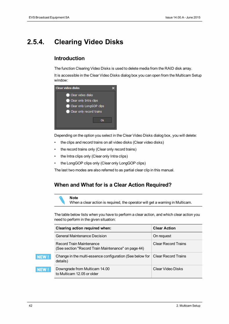
The function Clearing Video Disks is used to delete media from the RAID disk array.
It is accessible in the Clear Video Disks dialog box you can open from theMulticam Setupwindow:
Depending on the option you select in the Clear Video Disks dialog box, you will delete:
• the clips and record trains on all video disks (Clear video disks)
• the record trains only (Clear only record trains)
• the Intra clips only (Clear only Intra clips)
• the LongGOP clips only (Clear only LongGOP clips)
The last twomodes are also referred to as partial clear clip in this manual.
When and What for is a Clear Action Required?
NoteWhen a clear action is required, the operator will get a warning in Multicam.
The table below lists when you have to perform a clear action, and which clear action youneed to perform in the given situation:
Clearing action required when: Clear Action
General Maintenance Decision On request
Record Train Maintenance(See section "Record Train Maintenance" on page 44)
Clear Record Trains
Change in themulti-essence configuration (See below fordetails)
Clear Record Trains
Downgrade fromMulticam 14.00toMulticam 12.05 or older
Clear Video Disks
42 2. MulticamSetup
EVSBroadcast Equipment SA Issue 14.00.A - June 2015
Clearing action required when: Clear Action
Swap from H3XP to H3X Clear Video Disks
Swap from SAS tray managed by H3Xto SAS tray managed by H3XP
Clear Video Disks
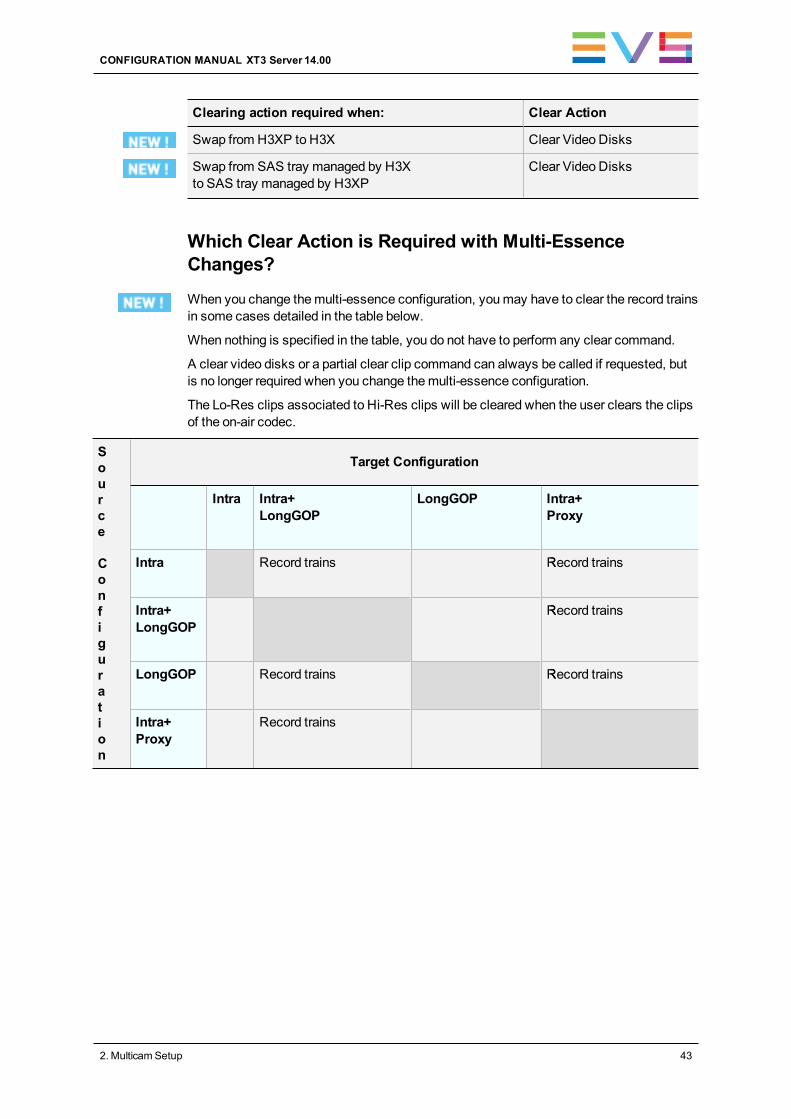
Which Clear Action is Required with Multi-EssenceChanges?
When you change themulti-essence configuration, youmay have to clear the record trainsin some cases detailed in the table below.
When nothing is specified in the table, you do not have to perform any clear command.
A clear video disks or a partial clear clip command can always be called if requested, butis no longer required when you change themulti-essence configuration.
The Lo-Res clips associated to Hi-Res clips will be cleared when the user clears the clipsof the on-air codec.
Source
Configuration
Target Configuration
Intra Intra+LongGOP
LongGOP Intra+Proxy
Intra Record trains Record trainsR
Intra+LongGOP
Record trainsR
LongGOP Record trains Record trainsR
Intra+Proxy
Record trains
CONFIGURATION MANUAL XT3 Server 14.00
2. MulticamSetup 43
How to Clear Clips and/or Trains in the Server-BasedApplication
To clear video disks in the server-based application, proceed as follows:
1. In theMulticam Setup window, press C to call theClear Video Disks command.
2. Select one of the available options and press ENTER.
A confirmationmessage is displayed.
3. Press RIGHT ARROW, andENTER to select Yes and validate the deletion.
OR
Press ENTER to cancel the deletion.
NoteAfter a Clear Video Disks action, the command toggles toUndo Clear VideoDisks At Next Start as long as your server has not been rebooted after theClear Video Disks command. This allows you to cancel theClear VideoDisks request.
How to Clear Clips/Trains in the Web-Based Interface
To clear video disks in the web-based interface, proceed as follows:
1. In theMulticam Setup window, click theClear video disks command from the Toolsarea to open theClear Video Diskswindow.
2. Select one of the available options and press OK.
A confirmationmessage is displayed.
3. Click Yes to validate the deletion orNo to cancel the deletion.
2.5.5. Record Train Maintenance
Preventing the Overflow of the Record Trains Field Counter
The record train uses a counter to identify each field being encoded in the server. Thiscounter will overflow after 2 years and 8months at 50 Hz or 2 years and 3months at59.94 Hz when the server is in continuous use.
When the field counter reaches its limit, the recorder and the player stop. It is possible toclose the current file and start a new one without the need to clear the video disks (asrequired in earlier versions of Multicam), nor to exit Multicam.
44 2. MulticamSetup
EVSBroadcast Equipment SA Issue 14.00.A - June 2015
How to Reset the Field Counter
You can reset the field counter from theMulticam Setup window, or from theMulticamConfiguration window:
To reset the counter from theMulticam Setup window, proceed as follows:
1. Go to theClear video disk dialog box.
2. Select Clear only record trains.
See section "Clearing Video Disks" on page 42
To reset the counter from theMulticam Configuration window, proceed as follows:
1. In the VGA, press SHIFT+F5 to open theServer Monitoringwindow.
2. In theGeneral Information page (page 1), select theReset record train command.
See section "General InformationWindow" on page 296
Impacts of the Field Counter Maintenance
During the field counter maintenance:
• The players that are using content from local clips are not be disturbed.
• The players that are using content from a remote (XNet) server are not disturbed.
• Playing out a record train of the server in field counter maintenance on a remote serverwill impact the playout.
After performing the field counter maintenance:
• All the trains are erased, but neither the clips nor the playlists are erased.
• Multicam restarts the recorders that were running before themaintenance operation.
• Multicam restarts the players that were running before themaintenance operation. Therecord train used by each player remains unchanged.
Automatic Advance Warning
As the recorders and the players will stop if the field counter reaches its limit, warnings areautomatically issued in advance:
• A message is displayed on the VGA 12weeks before the counter overflow, thenweekly from 8 to 4 weeks before the counter overflow.
• From 4weeks to the day before the counter overflow, themessage on the VGA isdisplayed daily, and the !Rec warning is displayed on all PGM OSD screens.
• On the last day, the OSD warning flashes.
CONFIGURATION MANUAL XT3 Server 14.00
2. MulticamSetup 45
Field Counter Overflow
When the field counter reaches the overflow:
• Multicam stops the recorders and the players.
• Multicam issues error messages on the VGA, the OSD, and the LSM.
• The operator is still allowed to browse andmake clips with all the content available onthe disks.
2.5.6. Importing and Exporting Keyword Files
Introduction
The keyword file is a simple text file with a name of 8 characters and a .KWD extension.All keyword files must be stored in the C:\LSMCE\DATA\KWD directory of the server. Asample keyword file (SAMPLE.KWD) is provided by EVS whenMulticam is installed.
You can also import and export keyword files to and from the EVS server via a USB key.
You can only perform this action in the server-based application.
How to Import a Keyword File
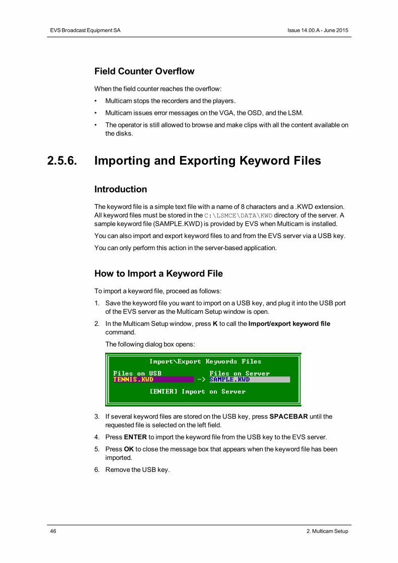
To import a keyword file, proceed as follows:
1. Save the keyword file you want to import on a USB key, and plug it into the USB portof the EVS server as theMulticam Setup window is open.
2. In theMulticam Setup window, press K to call the Import/export keyword filecommand.
The following dialog box opens:
3. If several keyword files are stored on the USB key, press SPACEBAR until therequested file is selected on the left field.
4. Press ENTER to import the keyword file from the USB key to the EVS server.
5. Press OK to close themessage box that appears when the keyword file has beenimported.
6. Remove the USB key.
46 2. MulticamSetup
EVSBroadcast Equipment SA Issue 14.00.A - June 2015
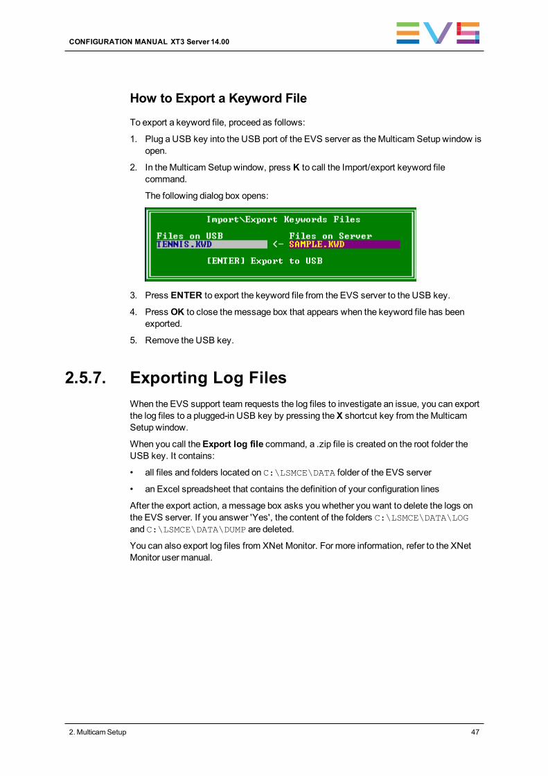
How to Export a Keyword File
To export a keyword file, proceed as follows:
1. Plug a USB key into the USB port of the EVS server as theMulticam Setup window isopen.
2. In theMulticam Setup window, press K to call the Import/export keyword filecommand.
The following dialog box opens:
3. Press ENTER to export the keyword file from the EVS server to the USB key.
4. Press OK to close themessage box that appears when the keyword file has beenexported.
5. Remove the USB key.
2.5.7. Exporting Log FilesWhen the EVS support team requests the log files to investigate an issue, you can exportthe log files to a plugged-in USB key by pressing theX shortcut key from theMulticamSetup window.
When you call theExport log file command, a .zip file is created on the root folder theUSB key. It contains:
• all files and folders located on C:\LSMCE\DATA folder of the EVS server
• an Excel spreadsheet that contains the definition of your configuration lines
After the export action, amessage box asks you whether you want to delete the logs onthe EVS server. If you answer 'Yes', the content of the folders C:\LSMCE\DATA\LOGand C:\LSMCE\DATA\DUMP are deleted.
You can also export log files from XNet Monitor. For more information, refer to the XNetMonitor user manual.
CONFIGURATION MANUAL XT3 Server 14.00
2. MulticamSetup 47
3. Supported Configurations
3.1. General Principles
3.1.1. About Supported Configurations
Generalities
Themain supported configurations on the various EVS servers are presented in agraphical and user-friendly way on the following webpage of the EVS website:http://www.evs.com/backpanel/index.html#
An XT3 server supports the following configurations types:
• Standard SD/HD configurations in 6-, 8- or 12-channel mode for XT3 6U and 4- or 7-channel mode for XT3 4U;
• SLSM SD/HD configurations in 6-, 8- or 12-channel mode for XT3 6U and 4- or 7-channel mode for XT3 4U;
• 3D/1080p configurations;
• SLSM 3D/1080p configurations;
• 4K configurations;
• SLSM 4K configurations;
Requirements and Limitations
• TheMix on one channel for play channels is available on all SD/HD configurations.
• The 12-channel mode is available in specific conditions. See section "AboutExtended Configurations" on page 51.
3.1.2. About Record and Play Channels
Number of Record and Play Channels
The number of record and play channels for a given configuration is defined in theChannels tab, in the Base settings. See section "Base Settings" on page 153.
The number of play and record channels available may differ depending on the chassis, onthe installed license codes, and on the configurations running on the XT3 server:
• Multicam LSMmode, when the EVS server is controlled by the Remote Panel.
• Spotbox mode, when the EVS server is controlled by the industry-standard protocols.
48 3. Supported Configurations
EVSBroadcast Equipment SA Issue 14.00.A - June 2015
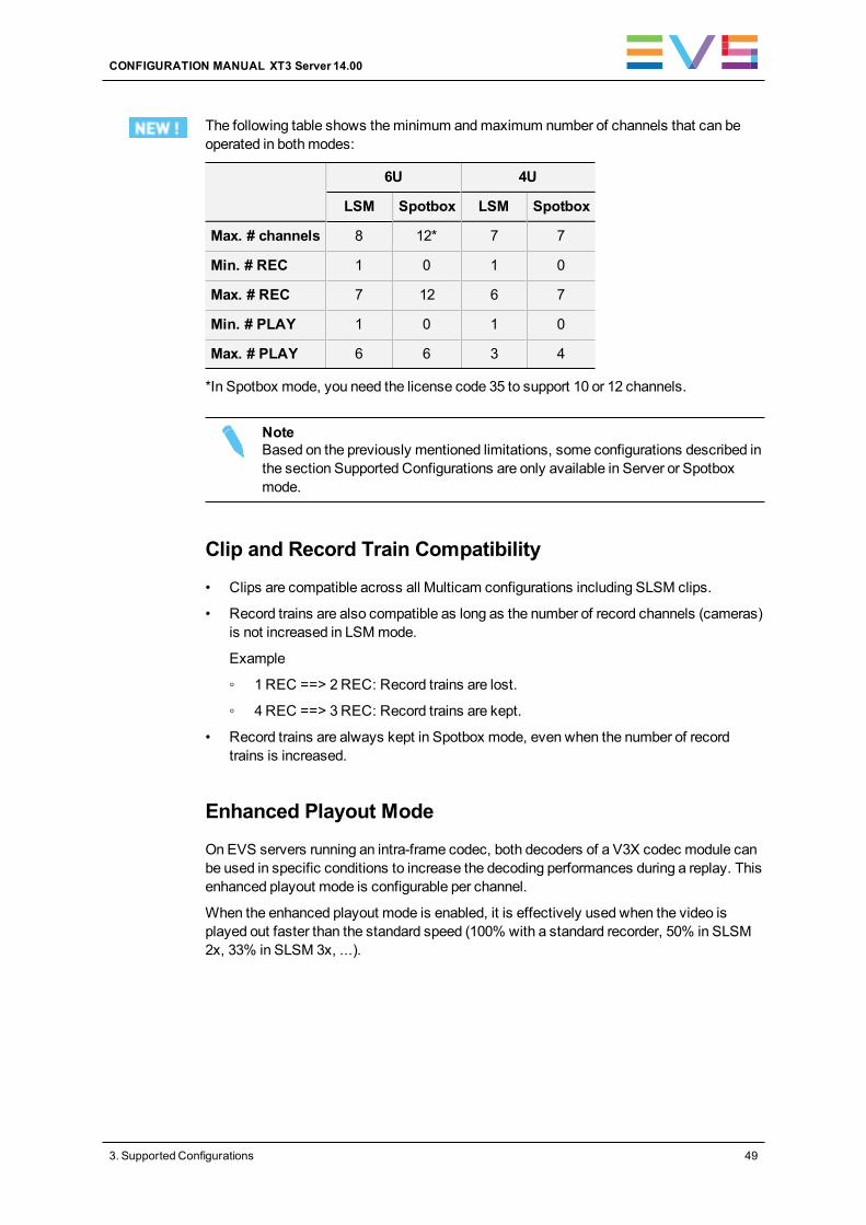
The following table shows theminimum andmaximum number of channels that can beoperated in bothmodes:
6U 4U
LSM Spotbox LSM Spotbox
Max. # channels 8 12* 7 7
Min. # REC 1 0 1 0
Max. # REC 7 12 6 7
Min. # PLAY 1 0 1 0
Max. # PLAY 6 6 3 4
*In Spotbox mode, you need the license code 35 to support 10 or 12 channels.
NoteBased on the previously mentioned limitations, some configurations described inthe section Supported Configurations are only available in Server or Spotboxmode.
Clip and Record Train Compatibility
• Clips are compatible across all Multicam configurations including SLSM clips.
• Record trains are also compatible as long as the number of record channels (cameras)is not increased in LSMmode.
Example
◦ 1 REC ==> 2REC: Record trains are lost.
◦ 4 REC ==> 3REC: Record trains are kept.
• Record trains are always kept in Spotbox mode, even when the number of recordtrains is increased.
Enhanced Playout Mode
OnEVS servers running an intra-frame codec, both decoders of a V3X codec module canbe used in specific conditions to increase the decoding performances during a replay. Thisenhanced playout mode is configurable per channel.
When the enhanced playout mode is enabled, it is effectively used when the video isplayed out faster than the standard speed (100% with a standard recorder, 50% in SLSM2x, 33% in SLSM 3x, ...).
CONFIGURATION MANUAL XT3 Server 14.00
3. Supported Configurations 49
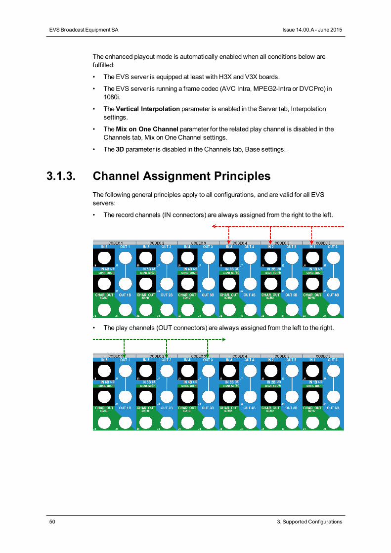
The enhanced playout mode is automatically enabled when all conditions below arefulfilled:
• The EVS server is equipped at least with H3X and V3X boards.
• The EVS server is running a frame codec (AVC Intra, MPEG2-Intra or DVCPro) in1080i.
• TheVertical Interpolation parameter is enabled in the Server tab, Interpolationsettings.
• TheMix on One Channel parameter for the related play channel is disabled in theChannels tab, Mix onOneChannel settings.
• The 3D parameter is disabled in the Channels tab, Base settings.
3.1.3. Channel Assignment PrinciplesThe following general principles apply to all configurations, and are valid for all EVSservers:
• The record channels (IN connectors) are always assigned from the right to the left.
• The play channels (OUT connectors) are always assigned from the left to the right.
50 3. Supported Configurations
EVSBroadcast Equipment SA Issue 14.00.A - June 2015
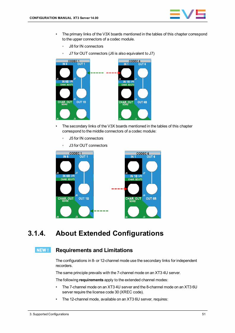
• The primary links of the V3X boards mentioned in the tables of this chapter correspondto the upper connectors of a codec module.
◦ J8 for IN connectors
◦ J7 for OUT connectors (J6 is also equivalent to J7)
• The secondary links of the V3X boards mentioned in the tables of this chaptercorrespond to themiddle connectors of a codec module:
◦ J5 for IN connectors
◦ J3 for OUT connectors
3.1.4. About Extended Configurations
Requirements and Limitations
The configurations in 8- or 12-channel mode use the secondary links for independentrecorders.
The same principle prevails with the 7-channel mode on an XT3 4U server.
The following requirements apply to the extended channel modes:
• The 7-channel mode on an XT3 4U server and the 8-channel mode on an XT3 6Userver require the license code 30 (XREC code).
• The 12-channel mode, available on an XT3 6U server, requires:
CONFIGURATION MANUAL XT3 Server 14.00
3. Supported Configurations 51
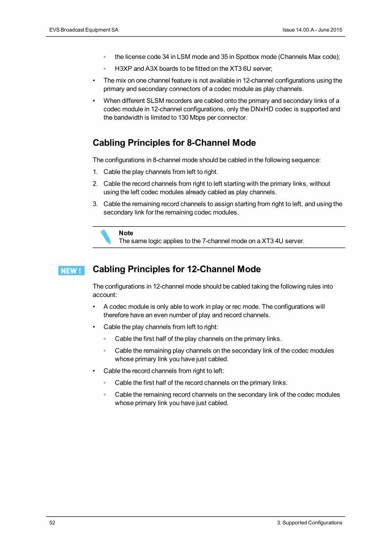
◦ the license code 34 in LSMmode and 35 in Spotbox mode (Channels Max code);
◦ H3XP and A3X boards to be fitted on the XT3 6U server;
• Themix on one channel feature is not available in 12-channel configurations using theprimary and secondary connectors of a codec module as play channels.
• When different SLSM recorders are cabled onto the primary and secondary links of acodec module in 12-channel configurations, only the DNxHD codec is supported andthe bandwidth is limited to 130Mbps per connector.
Cabling Principles for 8-Channel Mode
The configurations in 8-channel mode should be cabled in the following sequence:
1. Cable the play channels from left to right.
2. Cable the record channels from right to left starting with the primary links, withoutusing the left codec modules already cabled as play channels.
3. Cable the remaining record channels to assign starting from right to left, and using thesecondary link for the remaining codec modules.
NoteThe same logic applies to the 7-channel mode on a XT3 4U server.
Cabling Principles for 12-Channel Mode
The configurations in 12-channel mode should be cabled taking the following rules intoaccount:
• A codec module is only able to work in play or rec mode. The configurations willtherefore have an even number of play and record channels.
• Cable the play channels from left to right:
◦ Cable the first half of the play channels on the primary links.
◦ Cable the remaining play channels on the secondary link of the codec moduleswhose primary link you have just cabled.
• Cable the record channels from right to left:
◦ Cable the first half of the record channels on the primary links.
◦ Cable the remaining record channels on the secondary link of the codec moduleswhose primary link you have just cabled.
52 3. Supported Configurations
EVSBroadcast Equipment SA Issue 14.00.A - June 2015
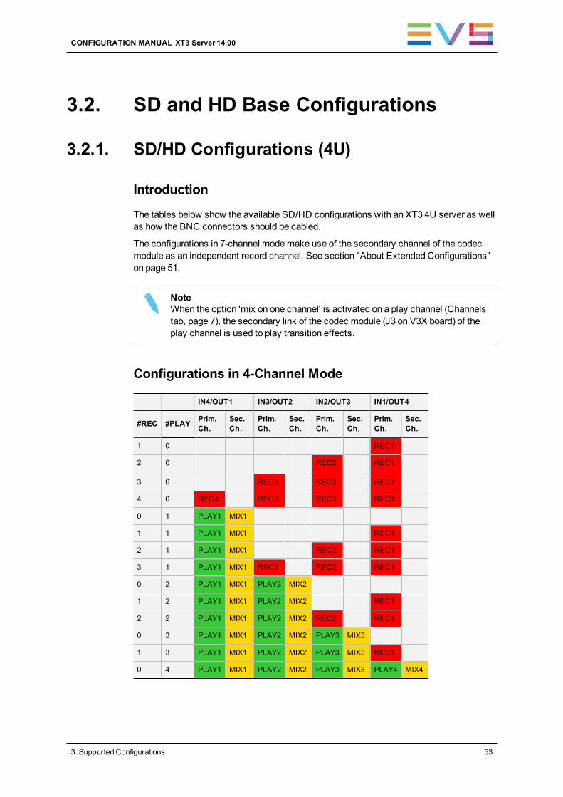
3.2. SD and HD Base Configurations
3.2.1. SD/HD Configurations (4U)
Introduction
The tables below show the available SD/HD configurations with an XT3 4U server as wellas how the BNC connectors should be cabled.
The configurations in 7-channel modemake use of the secondary channel of the codecmodule as an independent record channel. See section "About Extended Configurations"on page 51.
NoteWhen the option 'mix on one channel' is activated on a play channel (Channelstab, page 7), the secondary link of the codec module (J3 on V3X board) of theplay channel is used to play transition effects.
Configurations in 4-Channel Mode
IN4/OUT1 IN3/OUT2 IN2/OUT3 IN1/OUT4
#REC #PLAY Prim.Ch.
Sec.Ch.
Prim.Ch.
Sec.Ch.
Prim.Ch.
Sec.Ch.
Prim.Ch.
Sec.Ch.
1 0 REC1
2 0 REC2 REC1
3 0 REC3 REC2 REC1
4 0 REC4 REC3 REC2 REC1
0 1 PLAY1 MIX1
1 1 PLAY1 MIX1 REC1
2 1 PLAY1 MIX1 REC2 REC1
3 1 PLAY1 MIX1 REC3 REC2 REC1
0 2 PLAY1 MIX1 PLAY2 MIX2
1 2 PLAY1 MIX1 PLAY2 MIX2 REC1
2 2 PLAY1 MIX1 PLAY2 MIX2 REC2 REC1
0 3 PLAY1 MIX1 PLAY2 MIX2 PLAY3 MIX3
1 3 PLAY1 MIX1 PLAY2 MIX2 PLAY3 MIX3 REC1
0 4 PLAY1 MIX1 PLAY2 MIX2 PLAY3 MIX3 PLAY4 MIX4
CONFIGURATION MANUAL XT3 Server 14.00
3. Supported Configurations 53

Example in 4-Channel Mode (3REC + 1PLAY)
The BNC connectors to be used as record and play channels in a standard 3REC 1PLAYconfiguration need to be cabled as shown below:
Configurations in 7-Channel Mode
IN4/OUT1 IN3/OUT2 IN2/OUT3 IN1/OUT4
#REC #PLAY Prim.Ch.
Sec.Ch.
Prim.Ch.
Sec.Ch.
Prim.Ch.
Sec.Ch.
Prim.Ch.
Sec.Ch.
4 1 PLAY1 MIX1 REC3 REC2 REC1 REC4
5 1 PLAY1 MIX1 REC3 REC2 REC5 REC1 REC4
6 1 PLAY1 MIX1 REC3 REC6 REC2 REC5 REC1 REC4
3 2 PLAY1 MIX1 PLAY2 MIX2 REC2 REC1 REC3
4 2 PLAY1 MIX1 PLAY2 MIX2 REC2 REC4 REC1 REC3
2 3 PLAY1 MIX1 PLAY2 MIX2 PLAY3 MIX3 REC1 REC2
Example in 7-Channel Mode (6REC + 1PLAY)
The BNC connectors to be used as record and play channels in a 6REC 1PLAYconfiguration need to be cabled as shown below:
54 3. Supported Configurations
EVSBroadcast Equipment SA Issue 14.00.A - June 2015
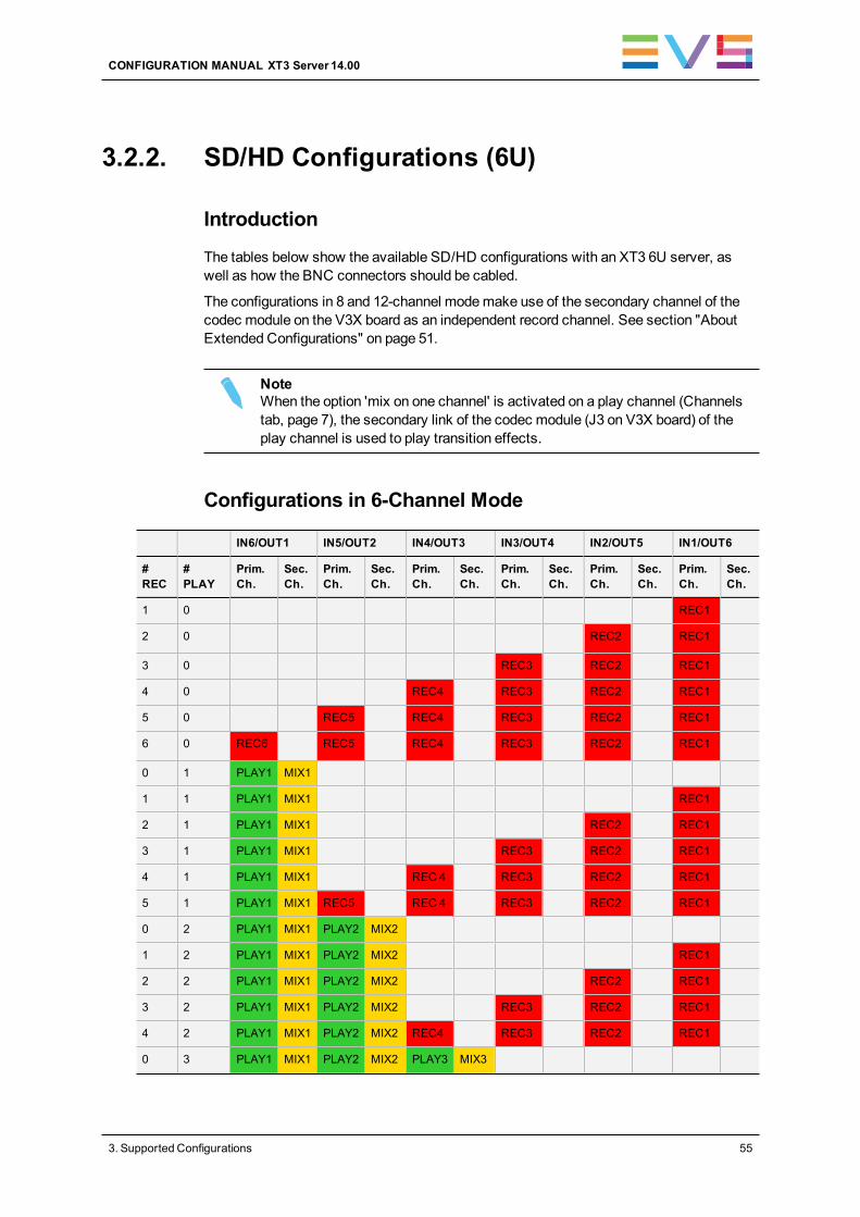
3.2.2. SD/HD Configurations (6U)
Introduction
The tables below show the available SD/HD configurations with an XT3 6U server, aswell as how the BNC connectors should be cabled.
The configurations in 8 and 12-channel modemake use of the secondary channel of thecodec module on the V3X board as an independent record channel. See section "AboutExtended Configurations" on page 51.
NoteWhen the option 'mix on one channel' is activated on a play channel (Channelstab, page 7), the secondary link of the codec module (J3 on V3X board) of theplay channel is used to play transition effects.
Configurations in 6-Channel Mode
IN6/OUT1 IN5/OUT2 IN4/OUT3 IN3/OUT4 IN2/OUT5 IN1/OUT6
#REC
#PLAY
Prim.Ch.
Sec.Ch.
Prim.Ch.
Sec.Ch.
Prim.Ch.
Sec.Ch.
Prim.Ch.
Sec.Ch.
Prim.Ch.
Sec.Ch.
Prim.Ch.
Sec.Ch.
1 0 REC1
2 0 REC2 REC1
3 0 REC3 REC2 REC1
4 0 REC4 REC3 REC2 REC1
5 0 REC5 REC4 REC3 REC2 REC1
6 0 REC6 REC5 REC4 REC3 REC2 REC1
0 1 PLAY1 MIX1
1 1 PLAY1 MIX1 REC1
2 1 PLAY1 MIX1 REC2 REC1
3 1 PLAY1 MIX1 REC3 REC2 REC1
4 1 PLAY1 MIX1 REC 4 REC3 REC2 REC1
5 1 PLAY1 MIX1 REC5 REC 4 REC3 REC2 REC1
0 2 PLAY1 MIX1 PLAY2 MIX2
1 2 PLAY1 MIX1 PLAY2 MIX2 REC1
2 2 PLAY1 MIX1 PLAY2 MIX2 REC2 REC1
3 2 PLAY1 MIX1 PLAY2 MIX2 REC3 REC2 REC1
4 2 PLAY1 MIX1 PLAY2 MIX2 REC4 REC3 REC2 REC1
0 3 PLAY1 MIX1 PLAY2 MIX2 PLAY3 MIX3
CONFIGURATION MANUAL XT3 Server 14.00
3. Supported Configurations 55
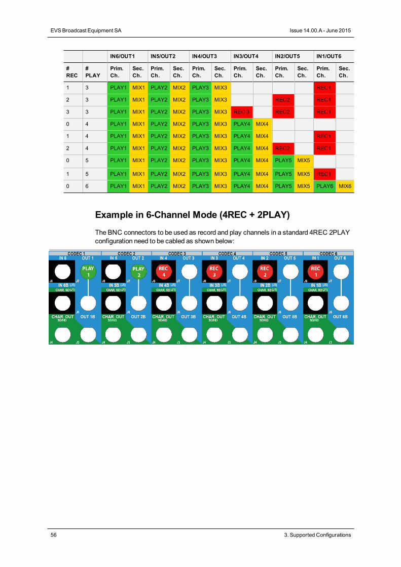
IN6/OUT1 IN5/OUT2 IN4/OUT3 IN3/OUT4 IN2/OUT5 IN1/OUT6
#REC
#PLAY
Prim.Ch.
Sec.Ch.
Prim.Ch.
Sec.Ch.
Prim.Ch.
Sec.Ch.
Prim.Ch.
Sec.Ch.
Prim.Ch.
Sec.Ch.
Prim.Ch.
Sec.Ch.
1 3 PLAY1 MIX1 PLAY2 MIX2 PLAY3 MIX3 REC1
2 3 PLAY1 MIX1 PLAY2 MIX2 PLAY3 MIX3 REC2 REC1
3 3 PLAY1 MIX1 PLAY2 MIX2 PLAY3 MIX3 REC 3 REC2 REC1
0 4 PLAY1 MIX1 PLAY2 MIX2 PLAY3 MIX3 PLAY4 MIX4
1 4 PLAY1 MIX1 PLAY2 MIX2 PLAY3 MIX3 PLAY4 MIX4 REC1
2 4 PLAY1 MIX1 PLAY2 MIX2 PLAY3 MIX3 PLAY4 MIX4 REC2 REC1
0 5 PLAY1 MIX1 PLAY2 MIX2 PLAY3 MIX3 PLAY4 MIX4 PLAY5 MIX5
1 5 PLAY1 MIX1 PLAY2 MIX2 PLAY3 MIX3 PLAY4 MIX4 PLAY5 MIX5 REC1
0 6 PLAY1 MIX1 PLAY2 MIX2 PLAY3 MIX3 PLAY4 MIX4 PLAY5 MIX5 PLAY6 MIX6
Example in 6-Channel Mode (4REC + 2PLAY)
The BNC connectors to be used as record and play channels in a standard 4REC 2PLAYconfiguration need to be cabled as shown below:
56 3. Supported Configurations
EVSBroadcast Equipment SA Issue 14.00.A - June 2015
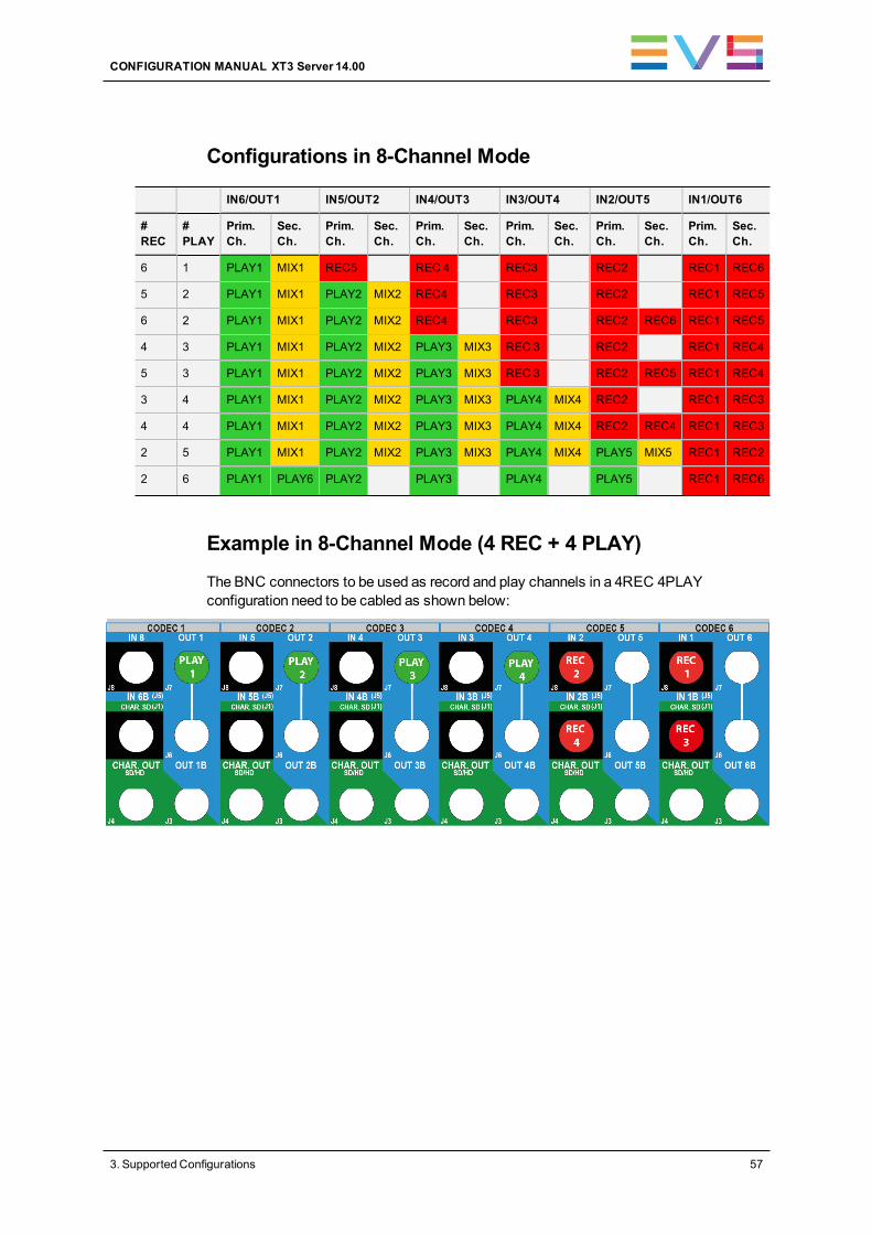
Configurations in 8-Channel Mode
IN6/OUT1 IN5/OUT2 IN4/OUT3 IN3/OUT4 IN2/OUT5 IN1/OUT6
#REC
#PLAY
Prim.Ch.
Sec.Ch.
Prim.Ch.
Sec.Ch.
Prim.Ch.
Sec.Ch.
Prim.Ch.
Sec.Ch.
Prim.Ch.
Sec.Ch.
Prim.Ch.
Sec.Ch.
6 1 PLAY1 MIX1 REC5 REC 4 REC3 REC2 REC1 REC6
5 2 PLAY1 MIX1 PLAY2 MIX2 REC4 REC3 REC2 REC1 REC5
6 2 PLAY1 MIX1 PLAY2 MIX2 REC4 REC3 REC2 REC6 REC1 REC5
4 3 PLAY1 MIX1 PLAY2 MIX2 PLAY3 MIX3 REC 3 REC2 REC1 REC4
5 3 PLAY1 MIX1 PLAY2 MIX2 PLAY3 MIX3 REC 3 REC2 REC5 REC1 REC4
3 4 PLAY1 MIX1 PLAY2 MIX2 PLAY3 MIX3 PLAY4 MIX4 REC2 REC1 REC3
4 4 PLAY1 MIX1 PLAY2 MIX2 PLAY3 MIX3 PLAY4 MIX4 REC2 REC4 REC1 REC3
2 5 PLAY1 MIX1 PLAY2 MIX2 PLAY3 MIX3 PLAY4 MIX4 PLAY5 MIX5 REC1 REC2
2 6 PLAY1 PLAY6 PLAY2 PLAY3 PLAY4 PLAY5 REC1 REC6
Example in 8-Channel Mode (4 REC + 4 PLAY)
The BNC connectors to be used as record and play channels in a 4REC 4PLAYconfiguration need to be cabled as shown below:
CONFIGURATION MANUAL XT3 Server 14.00
3. Supported Configurations 57
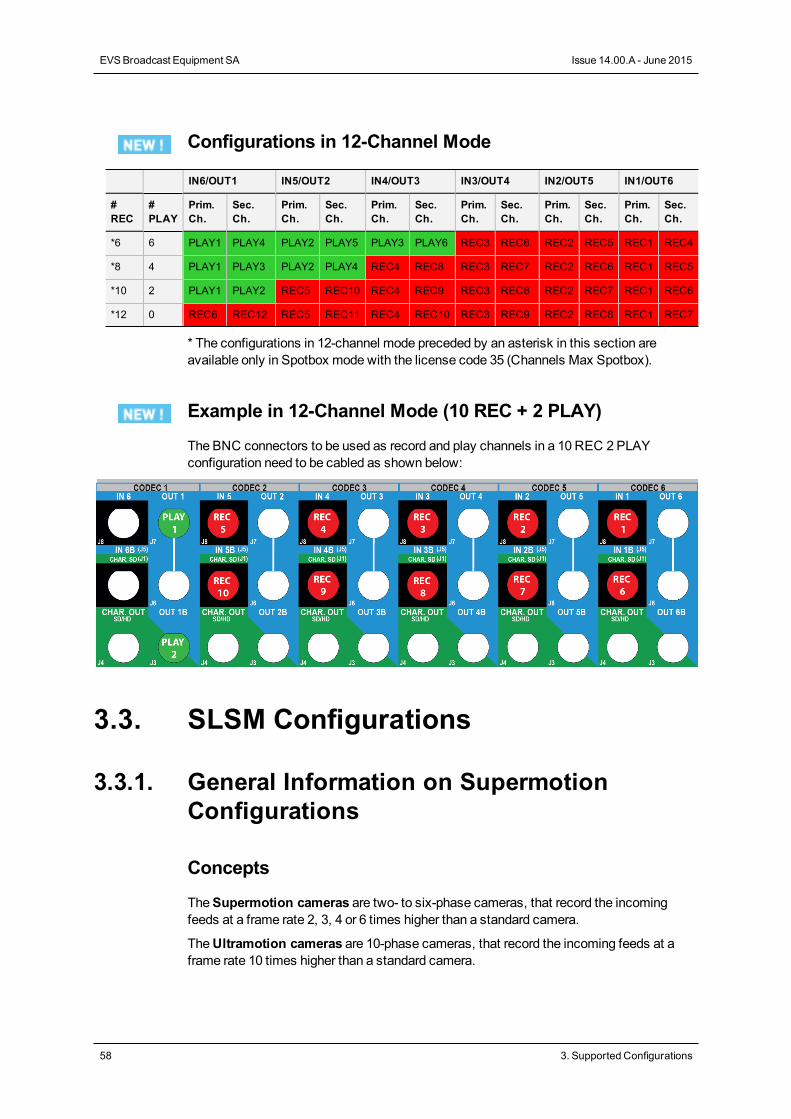
Configurations in 12-Channel Mode
IN6/OUT1 IN5/OUT2 IN4/OUT3 IN3/OUT4 IN2/OUT5 IN1/OUT6
#REC
#PLAY
Prim.Ch.
Sec.Ch.
Prim.Ch.
Sec.Ch.
Prim.Ch.
Sec.Ch.
Prim.Ch.
Sec.Ch.
Prim.Ch.
Sec.Ch.
Prim.Ch.
Sec.Ch.
*6 6 PLAY1 PLAY4 PLAY2 PLAY5 PLAY3 PLAY6 REC3 REC6 REC2 REC5 REC1 REC4
*8 4 PLAY1 PLAY3 PLAY2 PLAY4 REC4 REC8 REC3 REC7 REC2 REC6 REC1 REC5
*10 2 PLAY1 PLAY2 REC5 REC10 REC4 REC9 REC3 REC8 REC2 REC7 REC1 REC6
*12 0 REC6 REC12 REC5 REC11 REC4 REC10 REC3 REC9 REC2 REC8 REC1 REC7
* The configurations in 12-channel mode preceded by an asterisk in this section areavailable only in Spotbox mode with the license code 35 (Channels Max Spotbox).
Example in 12-Channel Mode (10 REC + 2 PLAY)
The BNC connectors to be used as record and play channels in a 10 REC 2 PLAYconfiguration need to be cabled as shown below:
3.3. SLSM Configurations
3.3.1. General Information on SupermotionConfigurations
Concepts
TheSupermotion cameras are two- to six-phase cameras, that record the incomingfeeds at a frame rate 2, 3, 4 or 6 times higher than a standard camera.
TheUltramotion cameras are 10-phase cameras, that record the incoming feeds at aframe rate 10 times higher than a standard camera.
58 3. Supported Configurations
EVSBroadcast Equipment SA Issue 14.00.A - June 2015
TheHypermotion cameras should clearly be distinguished from the supermotion andultramotion cameras in two respects:
• The A/V material from the supermotion and ultramotion cameras is continuously fedinto the EVS server, whereas the A/V material from the hypermotion cameras isrecorded on the camera buffer, and then ingested into the EVS server when theoperator sends a play command to the hypermotion camera.
• The A/V material from supermotion and ultramotion cameras is ingested into the EVSserver through one physical record channel per phase, whereas the A/V material fromthe hypermotion camera is ingested into the EVS server through one physical recordchannel.
See section "HypermotionManagement" on page 286 for more information on theconfiguration related to hypermotion cameras.
Introduction
The feeds from supermotion and ultramotion cameras can directly be ingested into EVSservers. The camera's number of phases directly determines the number of physicalrecord channels used on the EVS server.
A two-phase camera will use two physical record channels (primary or secondary channelwith V3X), a three-phase camera will use three physical record channels, and so on.
For supermotion two-phase or six-phase cameras, you can use a 3G-SDI connection(single cable) to connect your camera to both physical channels of a codec module(primary and secondary channels) at a time.
Limitation
Multi-Essence
With SLSM configurations in multi-essence Intra + LongGOP, the following limitationprevails:
• the Intra codec records all phases
• the LongGOP codec records only the regular speed content (not SLSM) from phase 1.
Extended Configurations
SLSM configurations with more than 12 physical channels are only available with thefollowing limitations:
• in DNxHD codec;
• with amaximum bitrate of 120Mbps in 50Hz (PAL) and 130Mbps in 60 Hz (NTSC).
This limitation applies, for example, to a configuration such as 2 x SLSM 6 phases + 2REC + 2 PLAY.
CONFIGURATION MANUAL XT3 Server 14.00
3. Supported Configurations 59
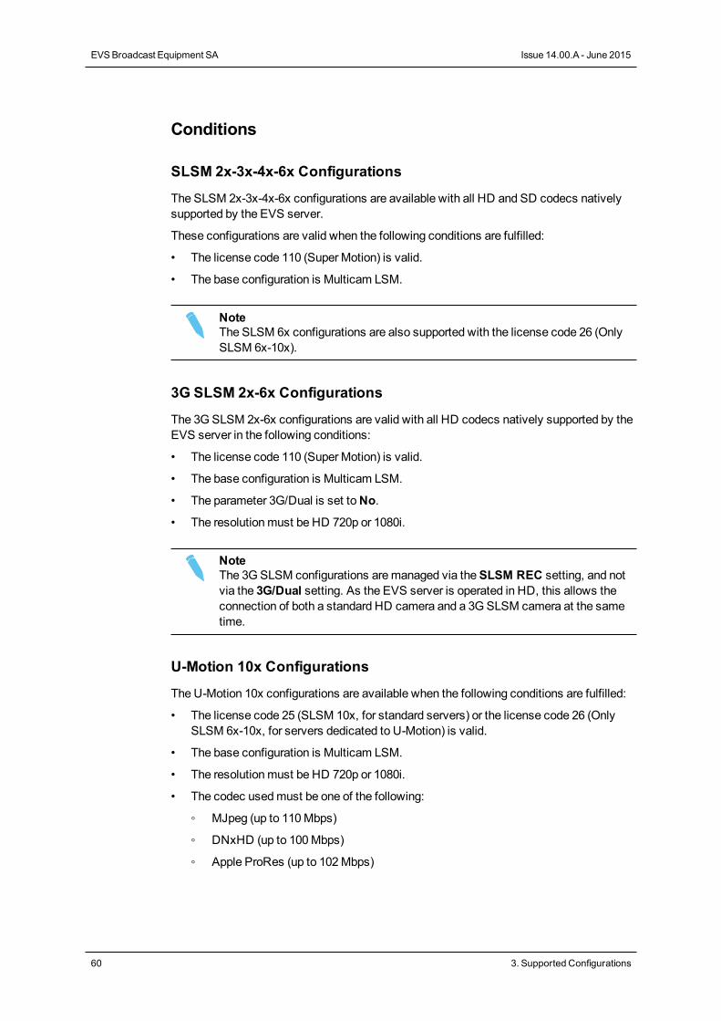
Conditions
SLSM 2x-3x-4x-6x Configurations
The SLSM 2x-3x-4x-6x configurations are available with all HD and SD codecs nativelysupported by the EVS server.
These configurations are valid when the following conditions are fulfilled:
• The license code 110 (Super Motion) is valid.
• The base configuration is Multicam LSM.
NoteThe SLSM 6x configurations are also supported with the license code 26 (OnlySLSM 6x-10x).
3G SLSM 2x-6x Configurations
The 3GSLSM 2x-6x configurations are valid with all HD codecs natively supported by theEVS server in the following conditions:
• The license code 110 (Super Motion) is valid.
• The base configuration is Multicam LSM.
• The parameter 3G/Dual is set toNo.
• The resolutionmust be HD 720p or 1080i.
NoteThe 3GSLSM configurations aremanaged via theSLSM REC setting, and notvia the 3G/Dual setting. As the EVS server is operated in HD, this allows theconnection of both a standard HD camera and a 3GSLSM camera at the sametime.
U-Motion 10x Configurations
The U-Motion 10x configurations are available when the following conditions are fulfilled:
• The license code 25 (SLSM 10x, for standard servers) or the license code 26 (OnlySLSM 6x-10x, for servers dedicated to U-Motion) is valid.
• The base configuration is Multicam LSM.
• The resolutionmust be HD 720p or 1080i.
• The codec usedmust be one of the following:
◦ MJpeg (up to 110Mbps)
◦ DNxHD (up to 100Mbps)
◦ Apple ProRes (up to 102Mbps)
60 3. Supported Configurations
EVSBroadcast Equipment SA Issue 14.00.A - June 2015
Enhanced Playout Mode
OnEVS servers running an intra-frame codec, both channels of a V3X codec module canbe used in specific conditions to increase the decoding performances during a replay. Thisenhanced playout mode is configurable per channel and is available in SLSMconfigurations.
The way to enable and use the enhnaced playout mode is described inmore details in thesection "Enhanced Playout Mode" on page 49.
3.3.2. SLSM Configurations (4U)
Introduction
SLSM Principles
This section details the available multi-phase SLSM configurations on XT3 4U servers.
In SLSM configurations, a supermotion recorder of a two-, three-, four- or six-phasecamera accounts for one logical channel, but corresponds respectively to two, three, fouror six physical channels.
In 3G SLSM configurations, a supermotion recorder of a two- or six-phase cameraaccounts for one logical channel. On the rear panel, it uses respectively one or threeconnector(s), and is cabled on the primary connector of the codec module. On the V3Xboard, it uses both primary and secondary channels of that codec module.
About Tables and Examples
This chapter presents the available SLSM configurations with an XT3 4U server:
• The tables show the channel assignment at the level of the V3X board.
• The examples show how the BNC connectors should be cabled for a selectedconfiguration.
The configurations in 7-channel mode, presented at the end of the tables, make use of thesecondary channel of the codec module on the V3X board as an independent recordchannel. See also the section "About Extended Configurations" on page 51.
NoteSpecific SLSM configurations for 1080p/3D dual link and 3G configurations arepresented from the section "Channel Assignment Principles with 3D/1080pSLSM" on page 98.
CONFIGURATION MANUAL XT3 Server 14.00
3. Supported Configurations 61
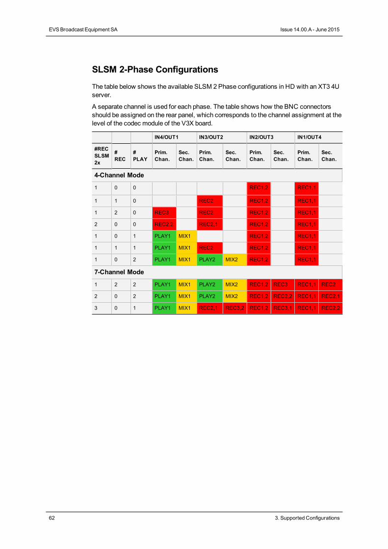
SLSM 2-Phase Configurations
The table below shows the available SLSM 2Phase configurations in HD with an XT3 4Userver.
A separate channel is used for each phase. The table shows how the BNC connectorsshould be assigned on the rear panel, which corresponds to the channel assignment at thelevel of the codec module of the V3X board.
IN4/OUT1 IN3/OUT2 IN2/OUT3 IN1/OUT4
#RECSLSM2x
#REC
#PLAY
Prim.Chan.
Sec.Chan.
Prim.Chan.
Sec.Chan.
Prim.Chan.
Sec.Chan.
Prim.Chan.
Sec.Chan.
4-Channel Mode
1 0 0 REC1,2 REC1,1
1 1 0 REC2 REC1,2 REC1,1
1 2 0 REC3 REC2 REC1,2 REC1,1
2 0 0 REC2,2 REC2,1 REC1,2 REC1,1
1 0 1 PLAY1 MIX1 REC1,2 REC1,1
1 1 1 PLAY1 MIX1 REC2 REC1,2 REC1,1
1 0 2 PLAY1 MIX1 PLAY2 MIX2 REC1,2 REC1,1
7-Channel Mode
1 2 2 PLAY1 MIX1 PLAY2 MIX2 REC1,2 REC3 REC1,1 REC2
2 0 2 PLAY1 MIX1 PLAY2 MIX2 REC1,2 REC2,2 REC1,1 REC2,1
3 0 1 PLAY1 MIX1 REC2,1 REC3,2 REC1,2 REC3,1 REC1,1 REC2,2
62 3. Supported Configurations
EVSBroadcast Equipment SA Issue 14.00.A - June 2015
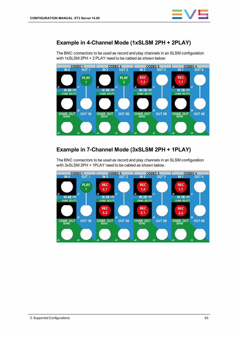
Example in 4-Channel Mode (1xSLSM 2PH + 2PLAY)
The BNC connectors to be used as record and play channels in an SLSM configurationwith 1xSLSM 2PH + 2 PLAY need to be cabled as shown below:
Example in 7-Channel Mode (3xSLSM 2PH + 1PLAY)
The BNC connectors to be used as record and play channels in an SLSM configurationwith 3xSLSM 2PH + 1PLAY need to be cabled as shown below.
CONFIGURATION MANUAL XT3 Server 14.00
3. Supported Configurations 63
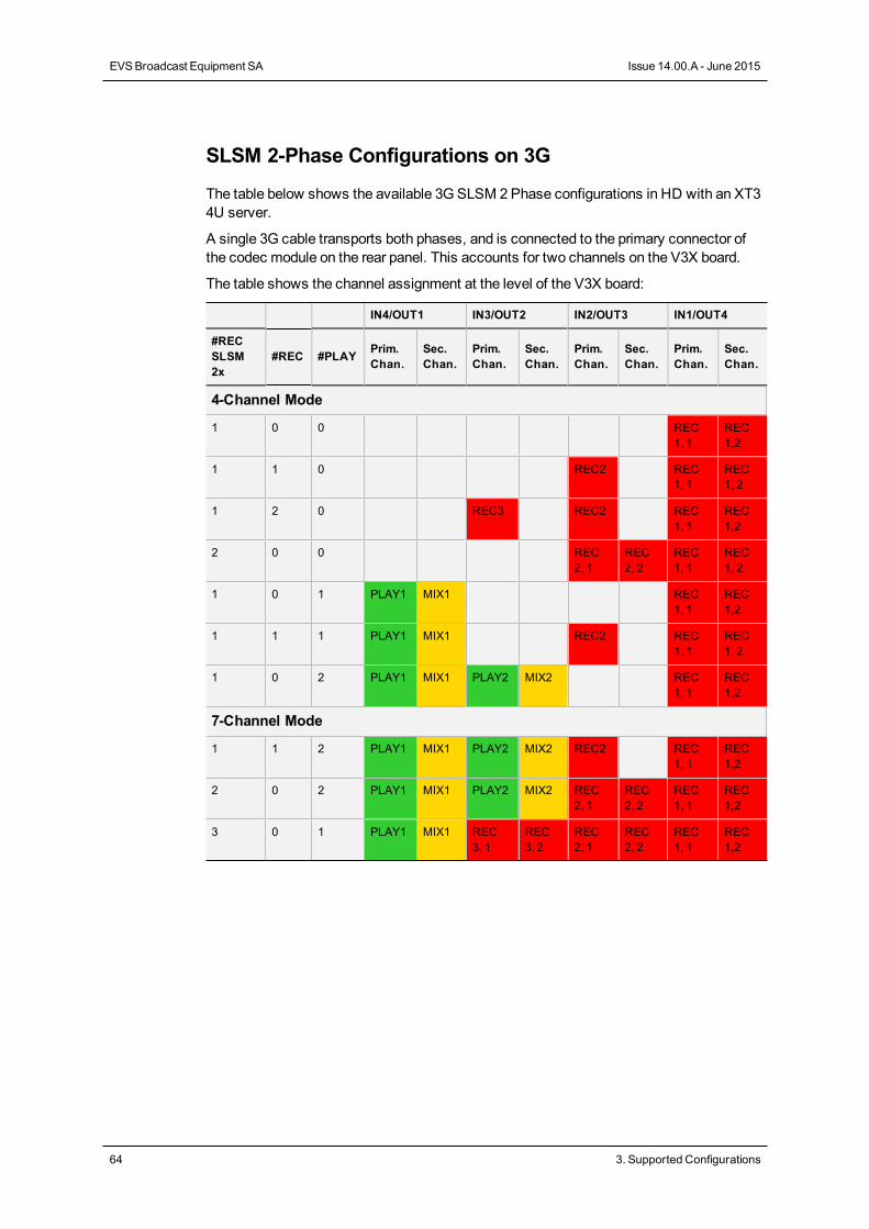
SLSM 2-Phase Configurations on 3G
The table below shows the available 3G SLSM 2Phase configurations in HD with an XT34U server.
A single 3G cable transports both phases, and is connected to the primary connector ofthe codec module on the rear panel. This accounts for two channels on the V3X board.
The table shows the channel assignment at the level of the V3X board:
IN4/OUT1 IN3/OUT2 IN2/OUT3 IN1/OUT4
#RECSLSM2x
#REC #PLAY Prim.Chan.
Sec.Chan.
Prim.Chan.
Sec.Chan.
Prim.Chan.
Sec.Chan.
Prim.Chan.
Sec.Chan.
4-Channel Mode
1 0 0 REC1, 1
REC1,2
1 1 0 REC2 REC1, 1
REC1, 2
1 2 0 REC3 REC2 REC1, 1
REC1,2
2 0 0 REC2, 1
REC2, 2
REC1, 1
REC1, 2
1 0 1 PLAY1 MIX1 REC1, 1
REC1,2
1 1 1 PLAY1 MIX1 REC2 REC1, 1
REC1, 2
1 0 2 PLAY1 MIX1 PLAY2 MIX2 REC1, 1
REC1,2
7-Channel Mode
1 1 2 PLAY1 MIX1 PLAY2 MIX2 REC2 REC1, 1
REC1,2
2 0 2 PLAY1 MIX1 PLAY2 MIX2 REC2, 1
REC2, 2
REC1, 1
REC1,2
3 0 1 PLAY1 MIX1 REC3, 1
REC3, 2
REC2, 1
REC2, 2
REC1, 1
REC1,2
64 3. Supported Configurations
EVSBroadcast Equipment SA Issue 14.00.A - June 2015
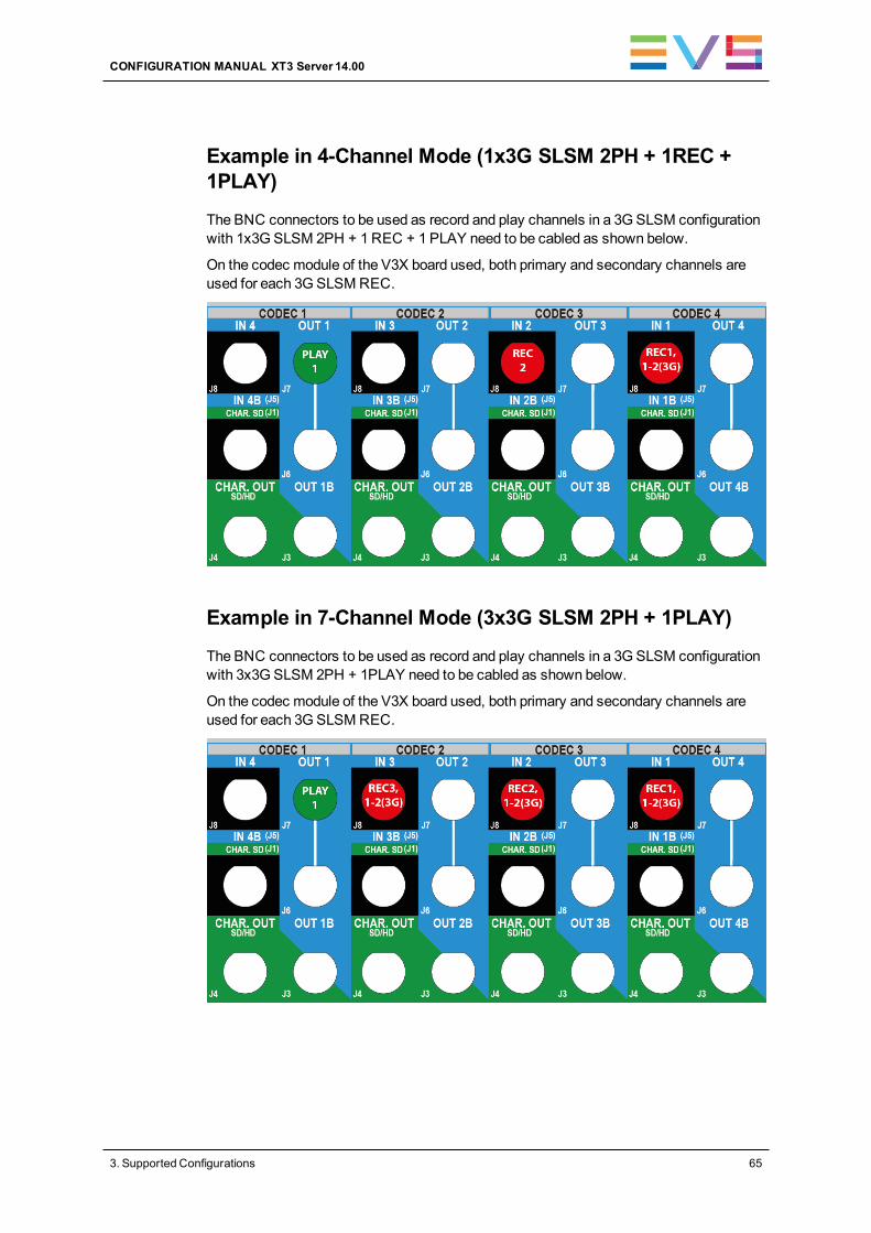
Example in 4-Channel Mode (1x3G SLSM 2PH + 1REC +1PLAY)
The BNC connectors to be used as record and play channels in a 3G SLSM configurationwith 1x3G SLSM 2PH + 1REC + 1 PLAY need to be cabled as shown below.
On the codec module of the V3X board used, both primary and secondary channels areused for each 3GSLSMREC.
Example in 7-Channel Mode (3x3G SLSM 2PH + 1PLAY)
The BNC connectors to be used as record and play channels in a 3G SLSM configurationwith 3x3G SLSM 2PH + 1PLAY need to be cabled as shown below.
On the codec module of the V3X board used, both primary and secondary channels areused for each 3GSLSMREC.
CONFIGURATION MANUAL XT3 Server 14.00
3. Supported Configurations 65
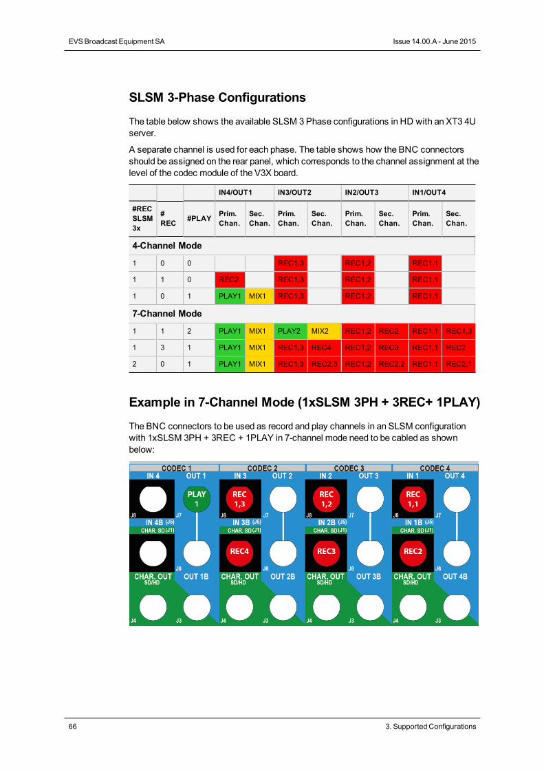
SLSM 3-Phase Configurations
The table below shows the available SLSM 3Phase configurations in HD with an XT3 4Userver.
A separate channel is used for each phase. The table shows how the BNC connectorsshould be assigned on the rear panel, which corresponds to the channel assignment at thelevel of the codec module of the V3X board.
IN4/OUT1 IN3/OUT2 IN2/OUT3 IN1/OUT4
#RECSLSM3x
#REC #PLAY Prim.
Chan.Sec.Chan.
Prim.Chan.
Sec.Chan.
Prim.Chan.
Sec.Chan.
Prim.Chan.
Sec.Chan.
4-Channel Mode
1 0 0 REC1,3 REC1,2 REC1,1
1 1 0 REC2 REC1,3 REC1,2 REC1,1
1 0 1 PLAY1 MIX1 REC1,3 REC1,2 REC1,1
7-Channel Mode
1 1 2 PLAY1 MIX1 PLAY2 MIX2 REC1,2 REC2 REC1,1 REC1,3
1 3 1 PLAY1 MIX1 REC1,3 REC4 REC1,2 REC3 REC1,1 REC2
2 0 1 PLAY1 MIX1 REC1,3 REC2,3 REC1,2 REC2,2 REC1,1 REC2,1
Example in 7-Channel Mode (1xSLSM 3PH + 3REC+ 1PLAY)
The BNC connectors to be used as record and play channels in an SLSM configurationwith 1xSLSM 3PH + 3REC + 1PLAY in 7-channel mode need to be cabled as shownbelow:
66 3. Supported Configurations
EVSBroadcast Equipment SA Issue 14.00.A - June 2015
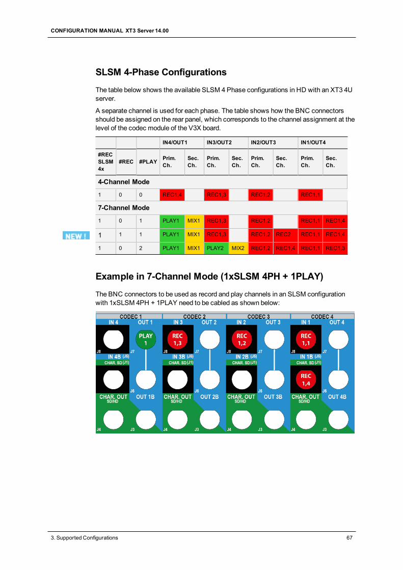
SLSM 4-Phase Configurations
The table below shows the available SLSM 4Phase configurations in HD with an XT3 4Userver.
A separate channel is used for each phase. The table shows how the BNC connectorsshould be assigned on the rear panel, which corresponds to the channel assignment at thelevel of the codec module of the V3X board.
IN4/OUT1 IN3/OUT2 IN2/OUT3 IN1/OUT4
#RECSLSM4x
#REC #PLAY Prim.Ch.
Sec.Ch.
Prim.Ch.
Sec.Ch.
Prim.Ch.
Sec.Ch.
Prim.Ch.
Sec.Ch.
4-Channel Mode
1 0 0 REC1,4 REC1,3 REC1,2 REC1,1
7-Channel Mode
1 0 1 PLAY1 MIX1 REC1,3 REC1,2 REC1,1 REC1,4
1 1 1 PLAY1 MIX1 REC1,3 REC1,2 REC2 REC1,1 REC1,4
1 0 2 PLAY1 MIX1 PLAY2 MIX2 REC1,2 REC1,4 REC1,1 REC1,3
Example in 7-Channel Mode (1xSLSM 4PH + 1PLAY)
The BNC connectors to be used as record and play channels in an SLSM configurationwith 1xSLSM 4PH + 1PLAY need to be cabled as shown below:
CONFIGURATION MANUAL XT3 Server 14.00
3. Supported Configurations 67
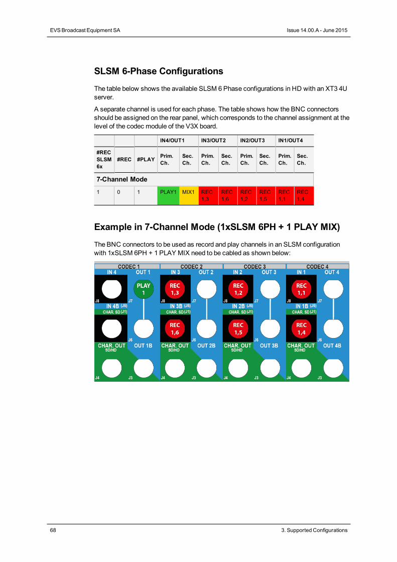
SLSM 6-Phase Configurations
The table below shows the available SLSM 6Phase configurations in HD with an XT3 4Userver.
A separate channel is used for each phase. The table shows how the BNC connectorsshould be assigned on the rear panel, which corresponds to the channel assignment at thelevel of the codec module of the V3X board.
IN4/OUT1 IN3/OUT2 IN2/OUT3 IN1/OUT4
#RECSLSM6x
#REC #PLAY Prim.Ch.
Sec.Ch.
Prim.Ch.
Sec.Ch.
Prim.Ch.
Sec.Ch.
Prim.Ch.
Sec.Ch.
7-Channel Mode
1 0 1 PLAY1 MIX1 REC1,3
REC1,6
REC1,2
REC1,5
REC1,1
REC1,4
Example in 7-Channel Mode (1xSLSM 6PH + 1 PLAY MIX)
The BNC connectors to be used as record and play channels in an SLSM configurationwith 1xSLSM 6PH + 1 PLAY MIX need to be cabled as shown below:
68 3. Supported Configurations
EVSBroadcast Equipment SA Issue 14.00.A - June 2015
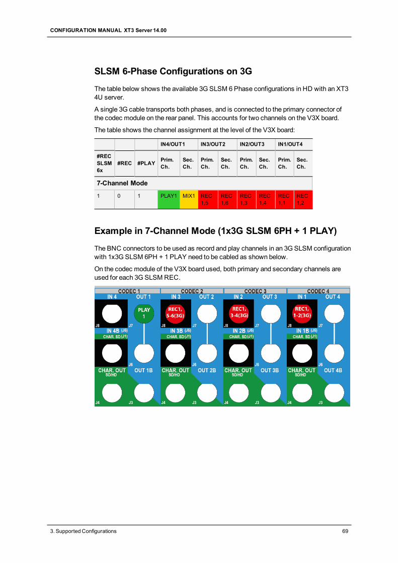
SLSM 6-Phase Configurations on 3G
The table below shows the available 3G SLSM 6Phase configurations in HD with an XT34U server.
A single 3G cable transports both phases, and is connected to the primary connector ofthe codec module on the rear panel. This accounts for two channels on the V3X board.
The table shows the channel assignment at the level of the V3X board:
IN4/OUT1 IN3/OUT2 IN2/OUT3 IN1/OUT4
#RECSLSM6x
#REC #PLAY Prim.Ch.
Sec.Ch.
Prim.Ch.
Sec.Ch.
Prim.Ch.
Sec.Ch.
Prim.Ch.
Sec.Ch.
7-Channel Mode
1 0 1 PLAY1 MIX1 REC1,5
REC1,6
REC1,3
REC1,4
REC1,1
REC1,2
Example in 7-Channel Mode (1x3G SLSM 6PH + 1 PLAY)
The BNC connectors to be used as record and play channels in an 3GSLSM configurationwith 1x3G SLSM 6PH + 1 PLAY need to be cabled as shown below.
On the codec module of the V3X board used, both primary and secondary channels areused for each 3GSLSMREC.
CONFIGURATION MANUAL XT3 Server 14.00
3. Supported Configurations 69
3.3.3. SLSM Configurations (6U)
Introduction
SLSM Principles
This section details the available multi-phase SLSM configurations on XT3 6U servers.
In SLSM configurations, a supermotion recorder of a two-, three-, four- or six-phasecamera accounts for one logical channel, but corresponds respectively to two, three, fouror six physical channels.
In 3G SLSM configurations, a supermotion recorder of a two- or six-phase cameraaccounts for one logical channel. On the rear panel, it uses respectively one or threeconnector(s), and is cabled on the primary connector of the codec module. On the V3Xboard, it uses both primary and secondary channels of that codec module.
In U-Motion configurations, an ultramotion recorder of a ten-phase camera accounts forone logical channel, but corresponds respectively to ten physical channels.
About Tables and Examples
This chapter presents the available SLSM andU-Motion configurations with an XT3 6Userver:
• The tables show the channel assignment at the level of the V3X board.
• The examples show how the BNC connectors should be cabled for a selectedconfiguration.
The configurations in 8 and 12-channel modemake use of the secondary channel of thecodec module on the V3X board as an independent record channel. See section "AboutExtended Configurations" on page 51.
The configurations in 12-channel mode are by default available in Multicam LSMmodewith the license code 34. The configurations in 12-channel mode preceded by an asteriskin this section are available only in Spotbox mode with the license code 35 (Channels MaxSpotbox).
NoteSpecific SLSM configurations for 1080p/3D dual link and 3G configurations arepresented in the section "3D/1080p SLSM Configurations (6U)" on page 103.
SLSM 2-Phase Configurations
The table below shows the available SLSM 2Phase configurations in HD with an XT3 6Userver server.
A separate channel is used for each phase. The table shows how the BNC connectorsshould be assigned on the rear panel, which corresponds to the channel assignment at thelevel of the codec module of the V3X board.
70 3. Supported Configurations
EVSBroadcast Equipment SA Issue 14.00.A - June 2015
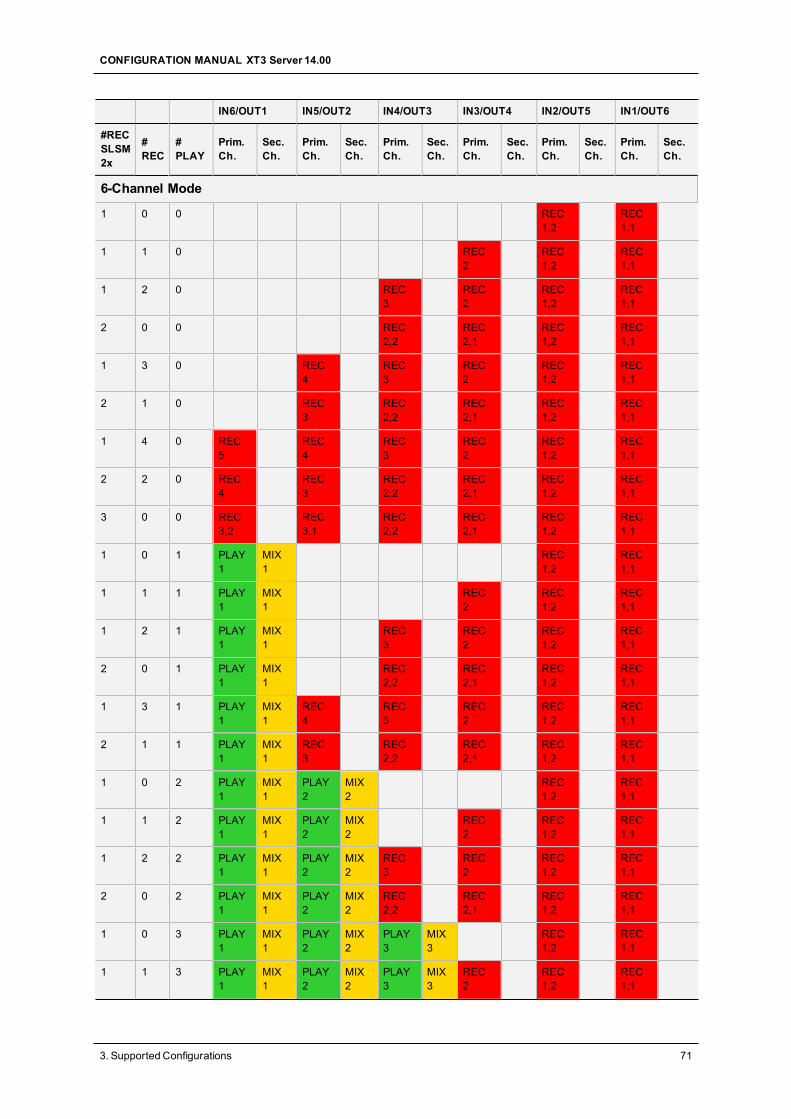
IN6/OUT1 IN5/OUT2 IN4/OUT3 IN3/OUT4 IN2/OUT5 IN1/OUT6
#RECSLSM2x
#REC
#PLAY
Prim.Ch.
Sec.Ch.
Prim.Ch.
Sec.Ch.
Prim.Ch.
Sec.Ch.
Prim.Ch.
Sec.Ch.
Prim.Ch.
Sec.Ch.
Prim.Ch.
Sec.Ch.
6-Channel Mode
1 0 0 REC1,2
REC1,1
1 1 0 REC2
REC1,2
REC1,1
1 2 0 REC3
REC2
REC1,2
REC1,1
2 0 0 REC2,2
REC2,1
REC1,2
REC1,1
1 3 0 REC4
REC3
REC2
REC1,2
REC1,1
2 1 0 REC3
REC2,2
REC2,1
REC1,2
REC1,1
1 4 0 REC5
REC4
REC3
REC2
REC1,2
REC1,1
2 2 0 REC4
REC3
REC2,2
REC2,1
REC1,2
REC1,1
3 0 0 REC3,2
REC3,1
REC2,2
REC2,1
REC1,2
REC1,1
1 0 1 PLAY1
MIX1
REC1,2
REC1,1
1 1 1 PLAY1
MIX1
REC2
REC1,2
REC1,1
1 2 1 PLAY1
MIX1
REC3
REC2
REC1,2
REC1,1
2 0 1 PLAY1
MIX1
REC2,2
REC2,1
REC1,2
REC1,1
1 3 1 PLAY1
MIX1
REC4
REC3
REC2
REC1,2
REC1,1
2 1 1 PLAY1
MIX1
REC3
REC2,2
REC2,1
REC1,2
REC1,1
1 0 2 PLAY1
MIX1
PLAY2
MIX2
REC1,2
REC1,1
1 1 2 PLAY1
MIX1
PLAY2
MIX2
REC2
REC1,2
REC1,1
1 2 2 PLAY1
MIX1
PLAY2
MIX2
REC3
REC2
REC1,2
REC1,1
2 0 2 PLAY1
MIX1
PLAY2
MIX2
REC2,2
REC2,1
REC1,2
REC1,1
1 0 3 PLAY1
MIX1
PLAY2
MIX2
PLAY3
MIX3
REC1,2
REC1,1
1 1 3 PLAY1
MIX1
PLAY2
MIX2
PLAY3
MIX3
REC2
REC1,2
REC1,1
CONFIGURATION MANUAL XT3 Server 14.00
3. Supported Configurations 71
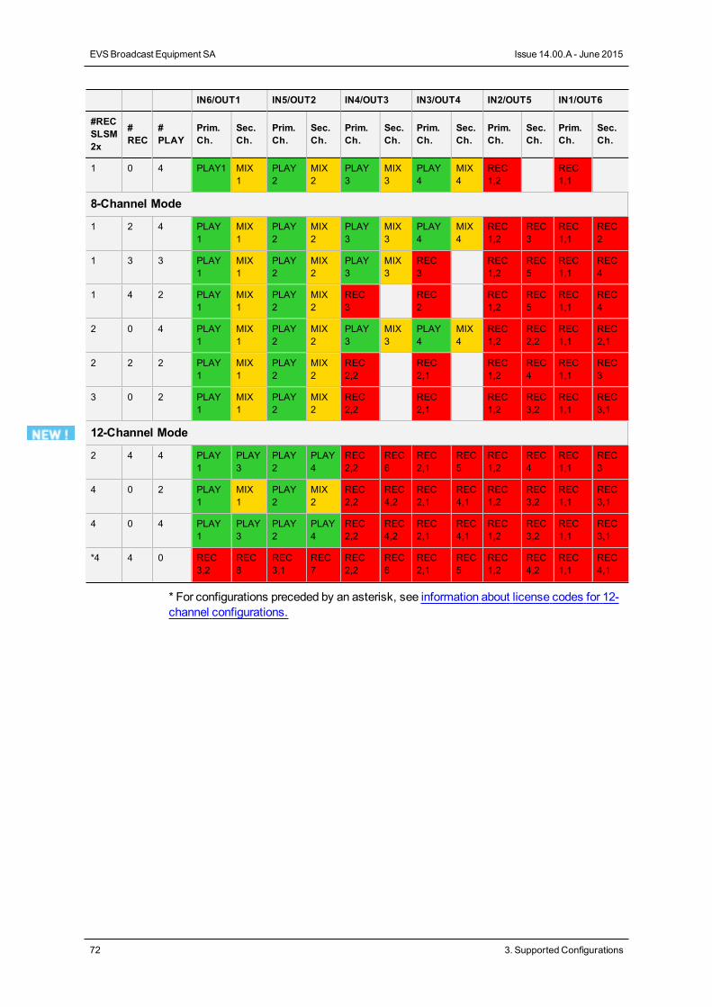
IN6/OUT1 IN5/OUT2 IN4/OUT3 IN3/OUT4 IN2/OUT5 IN1/OUT6
#RECSLSM2x
#REC
#PLAY
Prim.Ch.
Sec.Ch.
Prim.Ch.
Sec.Ch.
Prim.Ch.
Sec.Ch.
Prim.Ch.
Sec.Ch.
Prim.Ch.
Sec.Ch.
Prim.Ch.
Sec.Ch.
1 0 4 PLAY1 MIX1
PLAY2
MIX2
PLAY3
MIX3
PLAY4
MIX4
REC1,2
REC1,1
8-Channel Mode
1 2 4 PLAY1
MIX1
PLAY2
MIX2
PLAY3
MIX3
PLAY4
MIX4
REC1,2
REC3
REC1,1
REC2
1 3 3 PLAY1
MIX1
PLAY2
MIX2
PLAY3
MIX3
REC3
REC1,2
REC5
REC1,1
REC4
1 4 2 PLAY1
MIX1
PLAY2
MIX2
REC3
REC2
REC1,2
REC5
REC1,1
REC4
2 0 4 PLAY1
MIX1
PLAY2
MIX2
PLAY3
MIX3
PLAY4
MIX4
REC1,2
REC2,2
REC1,1
REC2,1
2 2 2 PLAY1
MIX1
PLAY2
MIX2
REC2,2
REC2,1
REC1,2
REC4
REC1,1
REC3
3 0 2 PLAY1
MIX1
PLAY2
MIX2
REC2,2
REC2,1
REC1,2
REC3,2
REC1,1
REC3,1
12-Channel Mode
2 4 4 PLAY1
PLAY3
PLAY2
PLAY4
REC2,2
REC6
REC2,1
REC5
REC1,2
REC4
REC1,1
REC3
4 0 2 PLAY1
MIX1
PLAY2
MIX2
REC2,2
REC4,2
REC2,1
REC4,1
REC1,2
REC3,2
REC1,1
REC3,1
4 0 4 PLAY1
PLAY3
PLAY2
PLAY4
REC2,2
REC4,2
REC2,1
REC4,1
REC1,2
REC3,2
REC1,1
REC3,1
*4 4 0 REC3,2
REC8
REC3,1
REC7
REC2,2
REC6
REC2,1
REC5
REC1,2
REC4,2
REC1,1
REC4,1
* For configurations preceded by an asterisk, see information about license codes for 12-channel configurations.
72 3. Supported Configurations
EVSBroadcast Equipment SA Issue 14.00.A - June 2015
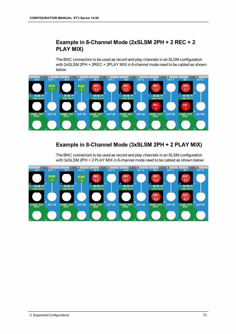
Example in 8-Channel Mode (2xSLSM 2PH + 2 REC + 2PLAY MIX)
The BNC connectors to be used as record and play channels in an SLSM configurationwith 2xSLSM 2PH + 2REC + 2PLAY MIX in 8-channel mode need to be cabled as shownbelow:
Example in 8-Channel Mode (3xSLSM 2PH + 2 PLAY MIX)
The BNC connectors to be used as record and play channels in an SLSM configurationwith 3xSLSM 2PH + 2 PLAY MIX in 8-channel mode need to be cabled as shown below:
CONFIGURATION MANUAL XT3 Server 14.00
3. Supported Configurations 73
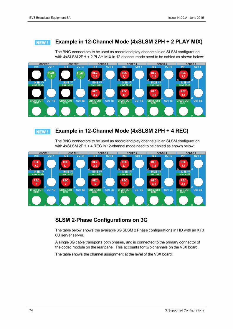
Example in 12-Channel Mode (4xSLSM 2PH + 2 PLAY MIX)
The BNC connectors to be used as record and play channels in an SLSM configurationwith 4xSLSM 2PH + 2 PLAY MIX in 12-channel mode need to be cabled as shown below:
Example in 12-Channel Mode (4xSLSM 2PH + 4 REC)
The BNC connectors to be used as record and play channels in an SLSM configurationwith 4xSLSM 2PH + 4REC in 12-channel mode need to be cabled as shown below:
SLSM 2-Phase Configurations on 3G
The table below shows the available 3G SLSM 2Phase configurations in HD with an XT36U server server.
A single 3G cable transports both phases, and is connected to the primary connector ofthe codec module on the rear panel. This accounts for two channels on the V3X board.
The table shows the channel assignment at the level of the V3X board:
74 3. Supported Configurations
EVSBroadcast Equipment SA Issue 14.00.A - June 2015

IN6/OUT1 IN5/OUT2 IN4/OUT3 IN3/OUT4 IN2/OUT5 IN1/OUT6
#RECSLSM2x
#REC #PLAY Prim.Ch.
Sec.Ch.
Prim.Ch.
Sec.Ch.
Prim.Ch.
Sec.Ch.
Prim.Ch.
Sec.Ch.
Prim.Ch.
Sec.Ch.
Prim.Ch.
Sec.Ch.
6-Channel Mode
1 0 0 REC1,1
REC1,2
1 1 0 REC2
REC1,1
REC1,2
1 2 0 REC3
REC2
REC1,1
REC1,2
1 3 0 REC4
REC3
REC2
REC1,1
REC1,2
1 4 0 REC 5 REC4
REC3
REC2
REC1,1
REC1,2
2 0 0 REC2,1
REC2,2
REC1,1
REC1,2
2 1 0 REC3
REC2,1
REC2,2
REC1,1
REC1,2
2 2 0 REC4
REC3
REC2,1
REC2,2
REC1,1
REC1,2
3 0 0 REC3,1
REC3,2
REC2,1
REC2,2
REC1,1
REC1,2
1 0 1 PLAY1
MIX1
REC1,1
REC1,2
1 0 2 PLAY1
MIX1
PLAY2
MIX2
REC1,1
REC1,2
1 0 3 PLAY1
MIX1
PLAY2
MIX2
PLAY3
MIX3
REC1,1
REC1,2
1 0 4 PLAY1 MIX1
PLAY2
MIX2
PLAY3
MIX3
PLAY4
MIX4
REC1,1
REC1,2
1 1 1 PLAY1
MIX1
REC2
REC1,1
REC1,2
1 1 2 PLAY1
MIX1
PLAY2
MIX2
REC2
REC1,1
REC1,2
1 2 1 PLAY1
MIX1
REC3
REC2
REC1,1
REC1,2
1 2 2 PLAY1
MIX1
PLAY2
MIX2
REC3
REC2
REC1,1
REC1,2
1 3 1 PLAY1
MIX1
REC4
REC3
REC2
REC1,1
REC1,2
2 0 1 PLAY1
MIX1
REC2,1
REC2,2
REC1,1
REC1,2
2 1 1 PLAY1
MIX1
REC3
REC2,1
REC2,2
REC1,1
REC1,2
2 0 2 PLAY1
MIX1
PLAY2
MIX2
REC2,1
REC2,2
REC1,1
REC1,2
CONFIGURATION MANUAL XT3 Server 14.00
3. Supported Configurations 75
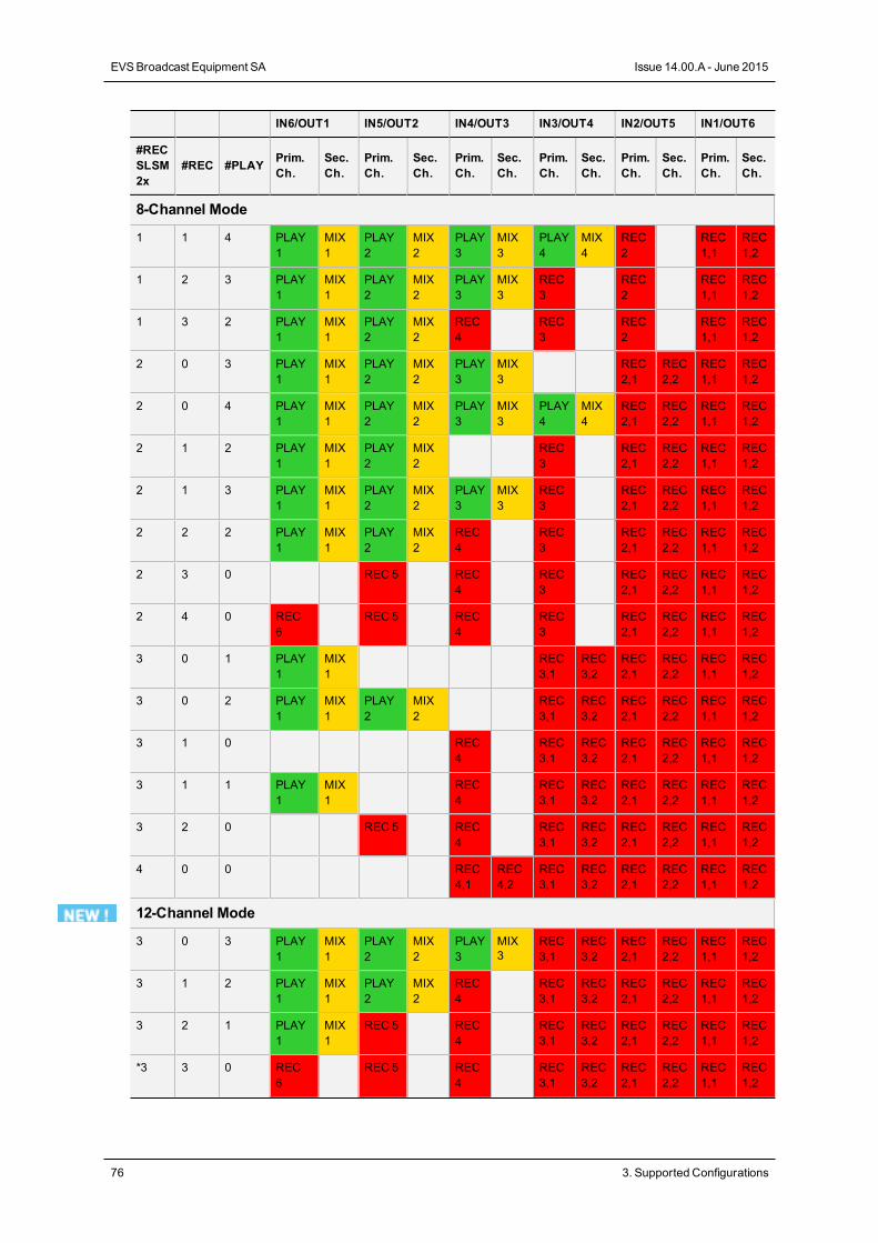
IN6/OUT1 IN5/OUT2 IN4/OUT3 IN3/OUT4 IN2/OUT5 IN1/OUT6
#RECSLSM2x
#REC #PLAY Prim.Ch.
Sec.Ch.
Prim.Ch.
Sec.Ch.
Prim.Ch.
Sec.Ch.
Prim.Ch.
Sec.Ch.
Prim.Ch.
Sec.Ch.
Prim.Ch.
Sec.Ch.
8-Channel Mode
1 1 4 PLAY1
MIX1
PLAY2
MIX2
PLAY3
MIX3
PLAY4
MIX4
REC2
REC1,1
REC1,2
1 2 3 PLAY1
MIX1
PLAY2
MIX2
PLAY3
MIX3
REC3
REC2
REC1,1
REC1,2
1 3 2 PLAY1
MIX1
PLAY2
MIX2
REC4
REC3
REC2
REC1,1
REC1,2
2 0 3 PLAY1
MIX1
PLAY2
MIX2
PLAY3
MIX3
REC2,1
REC2,2
REC1,1
REC1,2
2 0 4 PLAY1
MIX1
PLAY2
MIX2
PLAY3
MIX3
PLAY4
MIX4
REC2,1
REC2,2
REC1,1
REC1,2
2 1 2 PLAY1
MIX1
PLAY2
MIX2
REC3
REC2,1
REC2,2
REC1,1
REC1,2
2 1 3 PLAY1
MIX1
PLAY2
MIX2
PLAY3
MIX3
REC3
REC2,1
REC2,2
REC1,1
REC1,2
2 2 2 PLAY1
MIX1
PLAY2
MIX2
REC4
REC3
REC2,1
REC2,2
REC1,1
REC1,2
2 3 0 REC 5 REC4
REC3
REC2,1
REC2,2
REC1,1
REC1,2
2 4 0 REC6
REC 5 REC4
REC3
REC2,1
REC2,2
REC1,1
REC1,2
3 0 1 PLAY1
MIX1
REC3,1
REC3,2
REC2,1
REC2,2
REC1,1
REC1,2
3 0 2 PLAY1
MIX1
PLAY2
MIX2
REC3,1
REC3,2
REC2,1
REC2,2
REC1,1
REC1,2
3 1 0 REC4
REC3,1
REC3,2
REC2,1
REC2,2
REC1,1
REC1,2
3 1 1 PLAY1
MIX1
REC4
REC3,1
REC3,2
REC2,1
REC2,2
REC1,1
REC1,2
3 2 0 REC 5 REC4
REC3,1
REC3,2
REC2,1
REC2,2
REC1,1
REC1,2
4 0 0 REC4,1
REC4,2
REC3,1
REC3,2
REC2,1
REC2,2
REC1,1
REC1,2
12-Channel Mode
3 0 3 PLAY1
MIX1
PLAY2
MIX2
PLAY3
MIX3
REC3,1
REC3,2
REC2,1
REC2,2
REC1,1
REC1,2
3 1 2 PLAY1
MIX1
PLAY2
MIX2
REC4
REC3,1
REC3,2
REC2,1
REC2,2
REC1,1
REC1,2
3 2 1 PLAY1
MIX1
REC 5 REC4
REC3,1
REC3,2
REC2,1
REC2,2
REC1,1
REC1,2
*3 3 0 REC6
REC 5 REC4
REC3,1
REC3,2
REC2,1
REC2,2
REC1,1
REC1,2
76 3. Supported Configurations
EVSBroadcast Equipment SA Issue 14.00.A - June 2015
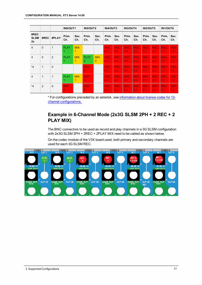
IN6/OUT1 IN5/OUT2 IN4/OUT3 IN3/OUT4 IN2/OUT5 IN1/OUT6
#RECSLSM2x
#REC #PLAY Prim.Ch.
Sec.Ch.
Prim.Ch.
Sec.Ch.
Prim.Ch.
Sec.Ch.
Prim.Ch.
Sec.Ch.
Prim.Ch.
Sec.Ch.
Prim.Ch.
Sec.Ch.
4 0 1 PLAY1
MIX1
REC4,1
REC4,2
REC3,1
REC3,2
REC2,1
REC2,2
REC1,1
REC1,2
4 0 2 PLAY1
MIX1
PLAY2
MIX2
REC4,1
REC4,2
REC3,1
REC3,2
REC2,1
REC2,2
REC1,1
REC1,2
*4 1 0 REC5
REC4,1
REC4,2
REC3,1
REC3,2
REC2,1
REC2,2
REC1,1
REC1,2
4 1 1 PLAY1
MIX1
REC5
REC4,1
REC4,2
REC3,1
REC3,2
REC2,1
REC2,2
REC1,1
REC1,2
*4 2 0 REC6
REC5
REC4,1
REC4,2
REC3,1
REC3,2
REC2,1
REC2,2
REC1,1
REC1,2
* For configurations preceded by an asterisk, see information about license codes for 12-channel configurations.
Example in 6-Channel Mode (2x3G SLSM 2PH + 2 REC + 2PLAY MIX)
The BNC connectors to be used as record and play channels in a 3G SLSM configurationwith 2x3G SLSM 2PH + 2REC + 2PLAY MIX need to be cabled as shown below.
On the codec module of the V3X board used, both primary and secondary channels areused for each 3GSLSMREC.
CONFIGURATION MANUAL XT3 Server 14.00
3. Supported Configurations 77
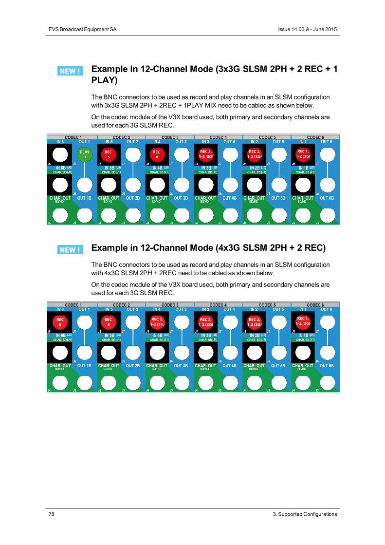
Example in 12-Channel Mode (3x3G SLSM 2PH + 2 REC + 1PLAY)
The BNC connectors to be used as record and play channels in an SLSM configurationwith 3x3G SLSM 2PH + 2REC + 1PLAY MIX need to be cabled as shown below.
On the codec module of the V3X board used, both primary and secondary channels areused for each 3GSLSMREC.
Example in 12-Channel Mode (4x3G SLSM 2PH + 2 REC)
The BNC connectors to be used as record and play channels in an SLSM configurationwith 4x3G SLSM 2PH + 2REC need to be cabled as shown below.
On the codec module of the V3X board used, both primary and secondary channels areused for each 3GSLSMREC.
78 3. Supported Configurations
EVSBroadcast Equipment SA Issue 14.00.A - June 2015
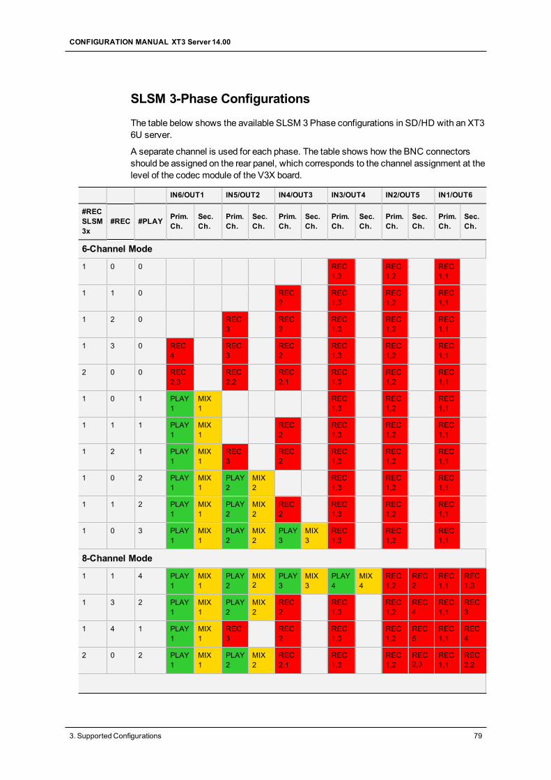
SLSM 3-Phase Configurations
The table below shows the available SLSM 3Phase configurations in SD/HD with an XT36U server.
A separate channel is used for each phase. The table shows how the BNC connectorsshould be assigned on the rear panel, which corresponds to the channel assignment at thelevel of the codec module of the V3X board.
IN6/OUT1 IN5/OUT2 IN4/OUT3 IN3/OUT4 IN2/OUT5 IN1/OUT6
#RECSLSM3x
#REC #PLAY Prim.Ch.
Sec.Ch.
Prim.Ch.
Sec.Ch.
Prim.Ch.
Sec.Ch.
Prim.Ch.
Sec.Ch.
Prim.Ch.
Sec.Ch.
Prim.Ch.
Sec.Ch.
6-Channel Mode
1 0 0 REC1,3
REC1,2
REC1,1
1 1 0 REC2
REC1,3
REC1,2
REC1,1
1 2 0 REC3
REC2
REC1,3
REC1,2
REC1,1
1 3 0 REC4
REC3
REC2
REC1,3
REC1,2
REC1,1
2 0 0 REC2,3
REC2,2
REC2,1
REC1,3
REC1,2
REC1,1
1 0 1 PLAY1
MIX1
REC1,3
REC1,2
REC1,1
1 1 1 PLAY1
MIX1
REC2
REC1,3
REC1,2
REC1,1
1 2 1 PLAY1
MIX1
REC3
REC2
REC1,3
REC1,2
REC1,1
1 0 2 PLAY1
MIX1
PLAY2
MIX2
REC1,3
REC1,2
REC1,1
1 1 2 PLAY1
MIX1
PLAY2
MIX2
REC2
REC1,3
REC1,2
REC1,1
1 0 3 PLAY1
MIX1
PLAY2
MIX2
PLAY3
MIX3
REC1,3
REC1,2
REC1,1
8-Channel Mode
1 1 4 PLAY1
MIX1
PLAY2
MIX2
PLAY3
MIX3
PLAY4
MIX4
REC1,2
REC2
REC1,1
REC1,3
1 3 2 PLAY1
MIX1
PLAY2
MIX2
REC2
REC1,3
REC1,2
REC4
REC1,1
REC3
1 4 1 PLAY1
MIX1
REC3
REC2
REC1,3
REC1,2
REC5
REC1,1
REC4
2 0 2 PLAY1
MIX1
PLAY2
MIX2
REC2,1
REC1,3
REC1,2
REC2,3
REC1,1
REC2,2
CONFIGURATION MANUAL XT3 Server 14.00
3. Supported Configurations 79
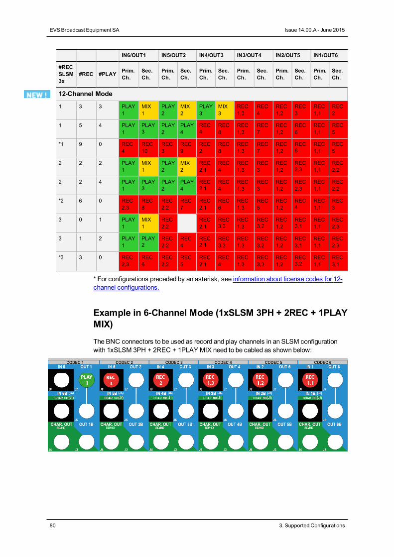
IN6/OUT1 IN5/OUT2 IN4/OUT3 IN3/OUT4 IN2/OUT5 IN1/OUT6
#RECSLSM3x
#REC #PLAY Prim.Ch.
Sec.Ch.
Prim.Ch.
Sec.Ch.
Prim.Ch.
Sec.Ch.
Prim.Ch.
Sec.Ch.
Prim.Ch.
Sec.Ch.
Prim.Ch.
Sec.Ch.
12-Channel Mode
1 3 3 PLAY1
MIX1
PLAY2
MIX2
PLAY3
MIX3
REC1,3
REC4
REC1,2
REC3
REC1,1
REC2
1 5 4 PLAY1
PLAY3
PLAY2
PLAY4
REC4
REC8
REC1,3
REC7
REC1,2
REC6
REC1,1
REC5
*1 9 0 REC4
REC10
REC3
REC9
REC2
REC8
REC1,3
REC7
REC1,2
REC6
REC1,1
REC5
2 2 2 PLAY1
MIX1
PLAY2
MIX2
REC2,1
REC4
REC1,3
REC3
REC1,2
REC2,3
REC1,1
REC2,2
2 2 4 PLAY1
PLAY3
PLAY2
PLAY4
REC2,1
REC4
REC1,3
REC3
REC1,2
REC2,3
REC1,1
REC2,2
*2 6 0 REC2,3
REC8
REC2,2
REC7
REC2,1
REC6
REC1,3
REC5
REC1,2
REC4
REC1,1
REC3
3 0 1 PLAY1
MIX1
REC2,2
REC2,1
REC3,3
REC1,3
REC3,2
REC1,2
REC3,1
REC1,1
REC2,3
3 1 2 PLAY1
PLAY2
REC2,2
REC4
REC2,1
REC3,3
REC1,3
REC3,2
REC1,2
REC3,1
REC1,1
REC2,3
*3 3 0 REC2,3
REC6
REC2,2
REC5
REC2,1
REC4
REC1,3
REC3,3
REC1,2
REC3,2
REC1,1
REC3,1
* For configurations preceded by an asterisk, see information about license codes for 12-channel configurations.
Example in 6-Channel Mode (1xSLSM 3PH + 2REC + 1PLAYMIX)
The BNC connectors to be used as record and play channels in an SLSM configurationwith 1xSLSM 3PH + 2REC + 1PLAY MIX need to be cabled as shown below:
80 3. Supported Configurations
EVSBroadcast Equipment SA Issue 14.00.A - June 2015
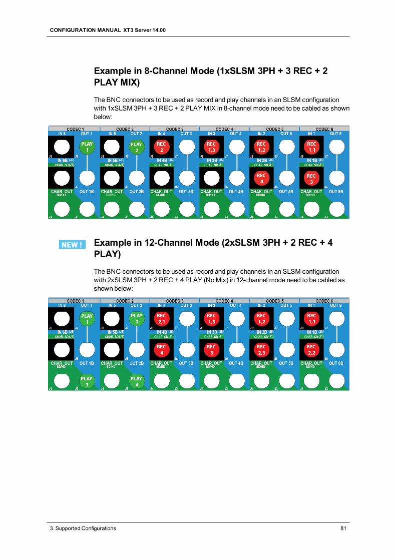
Example in 8-Channel Mode (1xSLSM 3PH + 3 REC + 2PLAY MIX)
The BNC connectors to be used as record and play channels in an SLSM configurationwith 1xSLSM 3PH + 3REC + 2 PLAY MIX in 8-channel mode need to be cabled as shownbelow:
Example in 12-Channel Mode (2xSLSM 3PH + 2 REC + 4PLAY)
The BNC connectors to be used as record and play channels in an SLSM configurationwith 2xSLSM 3PH + 2REC + 4 PLAY (NoMix) in 12-channel mode need to be cabled asshown below:
CONFIGURATION MANUAL XT3 Server 14.00
3. Supported Configurations 81
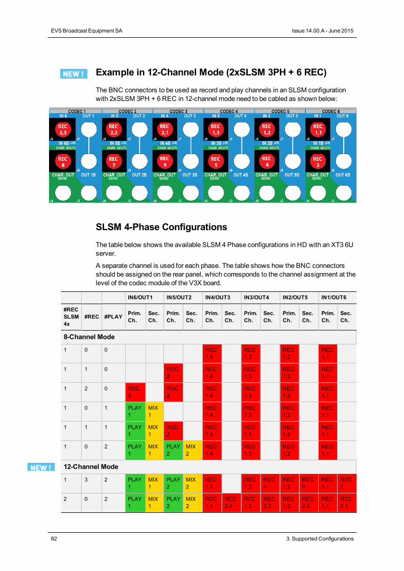
Example in 12-Channel Mode (2xSLSM 3PH + 6 REC)
The BNC connectors to be used as record and play channels in an SLSM configurationwith 2xSLSM 3PH + 6REC in 12-channel mode need to be cabled as shown below:
SLSM 4-Phase Configurations
The table below shows the available SLSM 4Phase configurations in HD with an XT3 6Userver.
A separate channel is used for each phase. The table shows how the BNC connectorsshould be assigned on the rear panel, which corresponds to the channel assignment at thelevel of the codec module of the V3X board.
IN6/OUT1 IN5/OUT2 IN4/OUT3 IN3/OUT4 IN2/OUT5 IN1/OUT6
#RECSLSM4x
#REC #PLAY Prim.Ch.
Sec.Ch.
Prim.Ch.
Sec.Ch.
Prim.Ch.
Sec.Ch.
Prim.Ch.
Sec.Ch.
Prim.Ch.
Sec.Ch.
Prim.Ch.
Sec.Ch.
8-Channel Mode
1 0 0 REC1,4
REC1,3
REC1,2
REC1,1
1 1 0 REC2
REC1,4
REC1,3
REC1,2
REC1,1
1 2 0 REC3
REC2
REC1,4
REC1,3
REC1,2
REC1,1
1 0 1 PLAY1
MIX1
REC1,4
REC1,3
REC1,2
REC1,1
1 1 1 PLAY1
MIX1
REC2
REC1,4
REC1,3
REC1,2
REC1,1
1 0 2 PLAY1
MIX1
PLAY2
MIX2
REC1,4
REC1,3
REC1,2
REC1,1
12-Channel Mode
1 3 2 PLAY1
MIX1
PLAY2
MIX2
REC1,4
REC1,3
REC4
REC1,2
REC3
REC1,1
REC2
2 0 2 PLAY1
MIX1
PLAY2
MIX2
REC1,4
REC2,4
REC1,3
REC2,3
REC1,2
REC2,2
REC1,1
REC2,1
82 3. Supported Configurations
EVSBroadcast Equipment SA Issue 14.00.A - June 2015
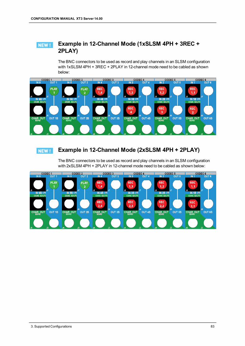
Example in 12-Channel Mode (1xSLSM 4PH + 3REC +2PLAY)
The BNC connectors to be used as record and play channels in an SLSM configurationwith 1xSLSM 4PH + 3REC + 2PLAY in 12-channel mode need to be cabled as shownbelow:
Example in 12-Channel Mode (2xSLSM 4PH + 2PLAY)
The BNC connectors to be used as record and play channels in an SLSM configurationwith 2xSLSM 4PH + 2PLAY in 12-channel mode need to be cabled as shown below:
CONFIGURATION MANUAL XT3 Server 14.00
3. Supported Configurations 83
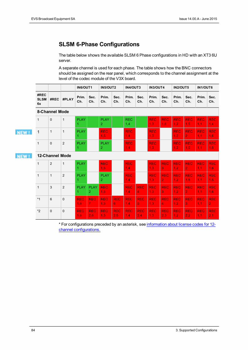
SLSM 6-Phase Configurations
The table below shows the available SLSM 6Phase configurations in HD with an XT3 6Userver.
A separate channel is used for each phase. The table shows how the BNC connectorsshould be assigned on the rear panel, which corresponds to the channel assignment at thelevel of the codec module of the V3X board.
IN6/OUT1 IN5/OUT2 IN4/OUT3 IN3/OUT4 IN2/OUT5 IN1/OUT6
#RECSLSM6x
#REC #PLAY Prim.Ch.
Sec.Ch.
Prim.Ch.
Sec.Ch.
Prim.Ch.
Sec.Ch.
Prim.Ch.
Sec.Ch.
Prim.Ch.
Sec.Ch.
Prim.Ch.
Sec.Ch.
8-Channel Mode
1 0 1 PLAY1
PLAY2
REC1,4
REC1,3
REC1,6
REC1,2
REC1,5
REC1,1
REC1,4
1 1 1 PLAY1
REC1,5
REC1,4
REC1,3
REC1,2
REC2
REC1,1
REC1,6
1 0 2 PLAY1
PLAY2
REC1,4
REC1,3
REC1,2
REC1,6
REC1,1
REC1,5
12-Channel Mode
1 2 1 PLAY1
REC1,5
REC1,4
REC1,3
REC3
REC1,2
REC2
REC1,1
REC1,6
1 1 2 PLAY1
PLAY2
REC1,4
REC1,3
REC2
REC1,2
REC1,6
REC1,1
REC1,5
1 3 2 PLAY1
PLAY2
REC1,5
REC1,4
REC4
REC1,3
REC3
REC1,2
REC2
REC1,1
REC1,6
*1 6 0 REC1,6
REC7
REC1,5
REC6
REC1,4
REC5
REC1,3
REC4
REC1,2
REC3
REC1,1
REC2
*2 0 0 REC1,6
REC2,6
REC1,5
REC2,5
REC1,4
REC2,4
REC1,3
REC2,3
REC1,2
REC2,2
REC1,1
REC2,1
* For configurations preceded by an asterisk, see information about license codes for 12-channel configurations.
84 3. Supported Configurations
EVSBroadcast Equipment SA Issue 14.00.A - June 2015
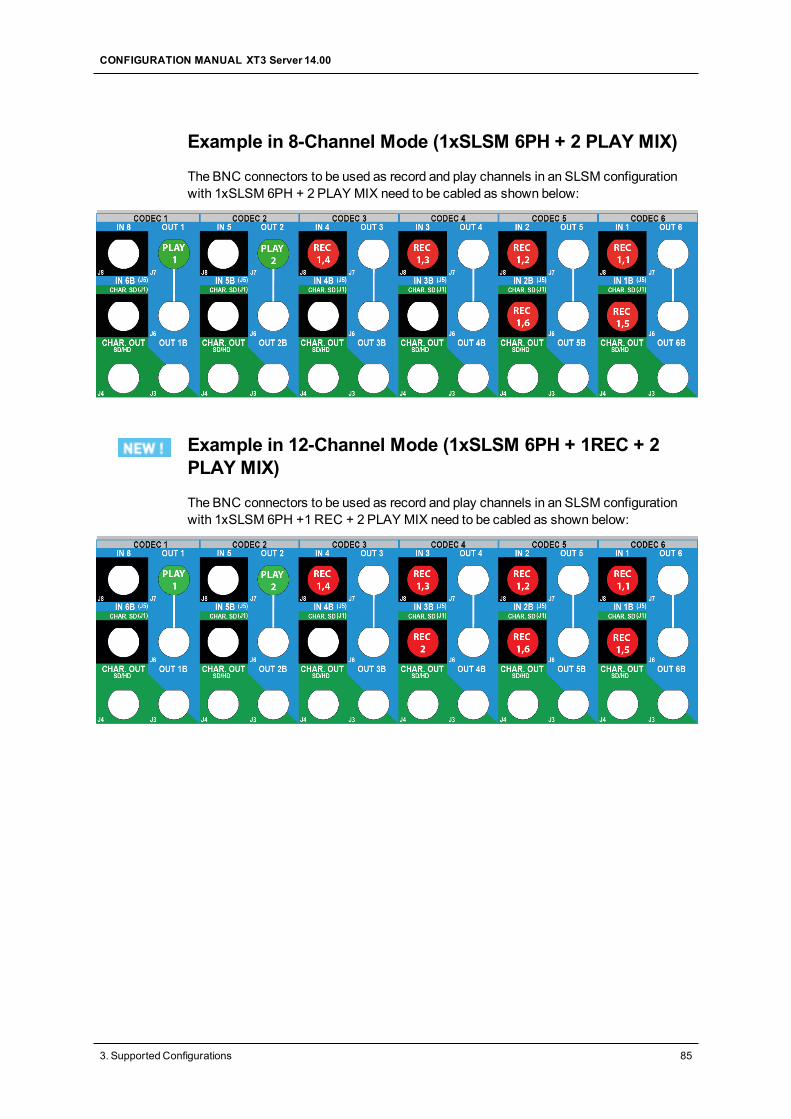
Example in 8-Channel Mode (1xSLSM 6PH + 2 PLAY MIX)
The BNC connectors to be used as record and play channels in an SLSM configurationwith 1xSLSM 6PH + 2 PLAY MIX need to be cabled as shown below:
Example in 12-Channel Mode (1xSLSM 6PH + 1REC + 2PLAY MIX)
The BNC connectors to be used as record and play channels in an SLSM configurationwith 1xSLSM 6PH +1REC + 2 PLAY MIX need to be cabled as shown below:
CONFIGURATION MANUAL XT3 Server 14.00
3. Supported Configurations 85
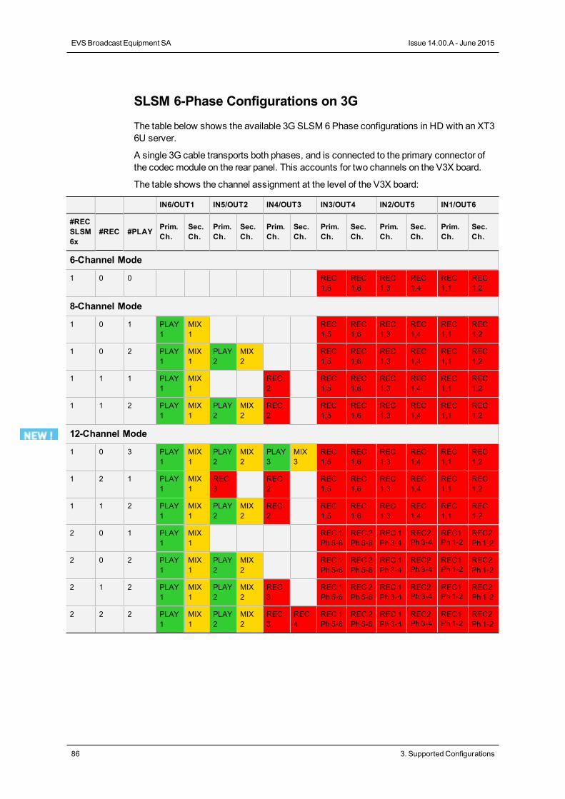
SLSM 6-Phase Configurations on 3G
The table below shows the available 3G SLSM 6Phase configurations in HD with an XT36U server.
A single 3G cable transports both phases, and is connected to the primary connector ofthe codec module on the rear panel. This accounts for two channels on the V3X board.
The table shows the channel assignment at the level of the V3X board:
IN6/OUT1 IN5/OUT2 IN4/OUT3 IN3/OUT4 IN2/OUT5 IN1/OUT6
#RECSLSM6x
#REC #PLAY Prim.Ch.
Sec.Ch.
Prim.Ch.
Sec.Ch.
Prim.Ch.
Sec.Ch.
Prim.Ch.
Sec.Ch.
Prim.Ch.
Sec.Ch.
Prim.Ch.
Sec.Ch.
6-Channel Mode
1 0 0 REC1,5
REC1,6
REC1,3
REC1,4
REC1,1
REC1,2
8-Channel Mode
1 0 1 PLAY1
MIX1
REC1,5
REC1,6
REC1,3
REC1,4
REC1,1
REC1,2
1 0 2 PLAY1
MIX1
PLAY2
MIX2
REC1,5
REC1,6
REC1,3
REC1,4
REC1,1
REC1,2
1 1 1 PLAY1
MIX1
REC2
REC1,5
REC1,6
REC1,3
REC1,4
REC1,1
REC1,2
1 1 2 PLAY1
MIX1
PLAY2
MIX2
REC2
REC1,5
REC1,6
REC1,3
REC1,4
REC1,1
REC1,2
12-Channel Mode
1 0 3 PLAY1
MIX1
PLAY2
MIX2
PLAY3
MIX3
REC1,5
REC1,6
REC1,3
REC1,4
REC1,1
REC1,2
1 2 1 PLAY1
MIX1
REC3
REC2
REC1,5
REC1,6
REC1,3
REC1,4
REC1,1
REC1,2
1 1 2 PLAY1
MIX1
PLAY2
MIX2
REC2
REC1,5
REC1,6
REC1,3
REC1,4
REC1,1
REC1,2
2 0 1 PLAY1
MIX1
REC 1Ph 5-6
REC 2Ph 5-6
REC 1Ph 3-4
REC2Ph 3-4
REC1Ph 1-2
REC2Ph 1-2
2 0 2 PLAY1
MIX1
PLAY2
MIX2
REC 1Ph 5-6
REC 2Ph 5-6
REC 1Ph 3-4
REC2Ph 3-4
REC1Ph 1-2
REC2Ph 1-2
2 1 2 PLAY1
MIX1
PLAY2
MIX2
REC3
REC 1Ph 5-6
REC 2Ph 5-6
REC 1Ph 3-4
REC2Ph 3-4
REC1Ph 1-2
REC2Ph 1-2
2 2 2 PLAY1
MIX1
PLAY2
MIX2
REC3
REC4
REC 1Ph 5-6
REC 2Ph 5-6
REC 1Ph 3-4
REC2Ph 3-4
REC1Ph 1-2
REC2Ph 1-2
86 3. Supported Configurations
EVSBroadcast Equipment SA Issue 14.00.A - June 2015
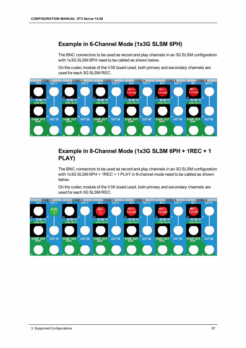
Example in 6-Channel Mode (1x3G SLSM 6PH)
The BNC connectors to be used as record and play channels in an 3GSLSM configurationwith 1x3G SLSM 6PH need to be cabled as shown below.
On the codec module of the V3X board used, both primary and secondary channels areused for each 3GSLSMREC.
Example in 8-Channel Mode (1x3G SLSM 6PH + 1REC + 1PLAY)
The BNC connectors to be used as record and play channels in an 3GSLSM configurationwith 1x3G SLSM 6PH + 1REC + 1 PLAY in 8-channel mode need to be cabled as shownbelow.
On the codec module of the V3X board used, both primary and secondary channels areused for each 3GSLSMREC.
CONFIGURATION MANUAL XT3 Server 14.00
3. Supported Configurations 87
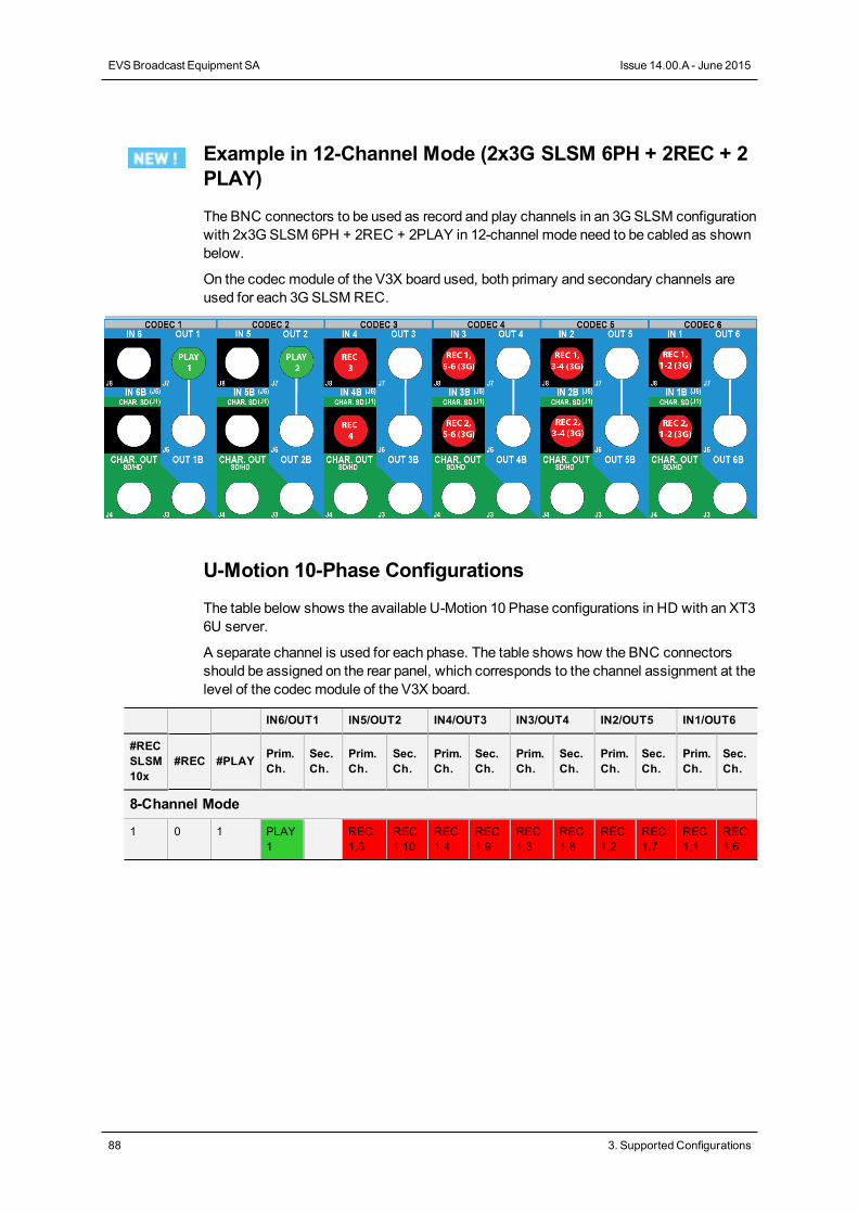
Example in 12-Channel Mode (2x3G SLSM 6PH + 2REC + 2PLAY)
The BNC connectors to be used as record and play channels in an 3GSLSM configurationwith 2x3G SLSM 6PH + 2REC + 2PLAY in 12-channel mode need to be cabled as shownbelow.
On the codec module of the V3X board used, both primary and secondary channels areused for each 3GSLSMREC.
U-Motion 10-Phase Configurations
The table below shows the available U-Motion 10 Phase configurations in HD with an XT36U server.
A separate channel is used for each phase. The table shows how the BNC connectorsshould be assigned on the rear panel, which corresponds to the channel assignment at thelevel of the codec module of the V3X board.
IN6/OUT1 IN5/OUT2 IN4/OUT3 IN3/OUT4 IN2/OUT5 IN1/OUT6
#RECSLSM10x
#REC #PLAY Prim.Ch.
Sec.Ch.
Prim.Ch.
Sec.Ch.
Prim.Ch.
Sec.Ch.
Prim.Ch.
Sec.Ch.
Prim.Ch.
Sec.Ch.
Prim.Ch.
Sec.Ch.
8-Channel Mode
1 0 1 PLAY1
REC1,5
REC1,10
REC1,4
REC1,9
REC1,3
REC1,8
REC1,2
REC1,7
REC1,1
REC1,6
88 3. Supported Configurations
EVSBroadcast Equipment SA Issue 14.00.A - June 2015
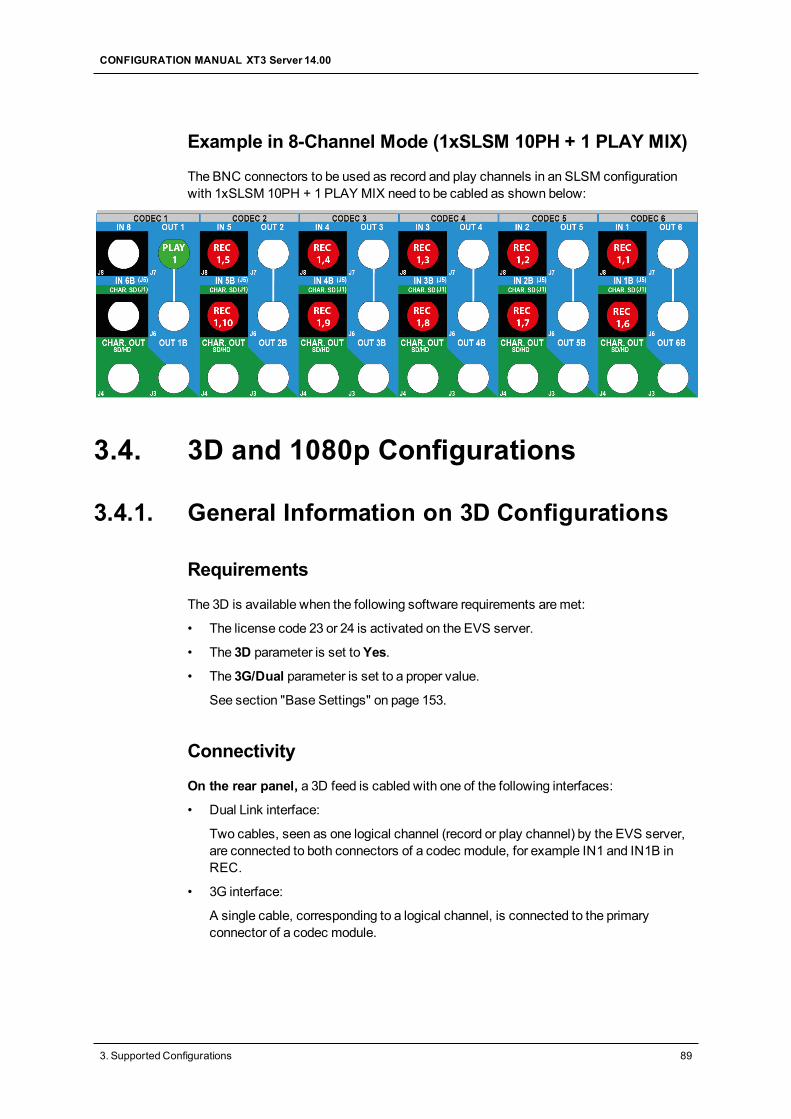
Example in 8-Channel Mode (1xSLSM 10PH + 1 PLAY MIX)
The BNC connectors to be used as record and play channels in an SLSM configurationwith 1xSLSM 10PH + 1 PLAY MIX need to be cabled as shown below:
3.4. 3D and 1080p Configurations
3.4.1. General Information on 3D Configurations
Requirements
The 3D is available when the following software requirements aremet:
• The license code 23 or 24 is activated on the EVS server.
• The 3D parameter is set toYes.
• The 3G/Dual parameter is set to a proper value.
See section "Base Settings" on page 153.
Connectivity
On the rear panel, a 3D feed is cabled with one of the following interfaces:
• Dual Link interface:
Two cables, seen as one logical channel (record or play channel) by the EVS server,are connected to both connectors of a codec module, for example IN1 and IN1B inREC.
• 3G interface:
A single cable, corresponding to a logical channel, is connected to the primaryconnector of a codec module.
CONFIGURATION MANUAL XT3 Server 14.00
3. Supported Configurations 89
On the V3X board, a 3D connection is connected as follows:
• Both primary and secondary channels of the codec module (COD A or COD B) on theV3X board are used whatever the connection interface to the rear panel (Dual Link or3G).
3.4.2. General Information on 1080pConfigurations
Introduction
Since an XT3 server runningMulticam 14.00 is at least fitted with an H3X and V3Xboards, the EVS video server working in 1080p encodes or decodes natively the full 1080pvideo in a single file on the EVS server. This provides file interoperability, without requiringtranscoding.
Requirements
The 1080p is available when the following software requirements aremet:
• The license code 21 or 22 is activated on the EVS server.
• The 3G/Dual parameter is set to a proper value.
See section "Base Settings" on page 153.
Limitations
Codec Limitations
1080p can only be used with Intra and Proxy codecs.
1080p only supports AVC-Intra, Avid DNxHD, and Apple ProRes 422 codecs.
1080p cannot be used with LongGOP codecs.
Configuration Limitations
1080p does not support theMix on one channel feature.
1080p configurations with more than 6 channels are only available with the followinglimitations:
• in DNxHD codec;
• with amaximum bitrate of 242Mbps in 50Hz (PAL) and 260Mbps in 60 Hz (NTSC).
This limitation applies, for example, to configurations such as 2 x SLSM 3 phases + 2PLAY or 1 x SLSM 6 phases + 1 REC + 2 PLAY.
90 3. Supported Configurations
EVSBroadcast Equipment SA Issue 14.00.A - June 2015
Connectivity
On the rear panel, a 1080p feed is cabled with one of the following interfaces:
• Dual Link interface:
Two cables, seen by the EVS server as one logical channel (record or play channel),are connected to both connectors of a codec module, for example IN1 and IN1B inREC.
• 3G interface:
A single cable, corresponding to a logical channel, is connected to the primaryconnector of a codec module.
On the V3X board, a 1080p connection is connected as follows:
• On 4 or 6-channel configurations, only the primary channel of the codec module(COD A) on the V3X board is used.
The connection to the secondary channel is no longer necessary since the full 1080pvideo is included in a single file on the EVS server.
In this case, the decoding/encoding capability of both channels of the V3X codecmodule is used without bandwidth restriction.
• On 8 or 12-channel configurations, the secondary channel of the codec module (CODA) on the V3X board can be used as an independent recorder, with the above-mentioned codec and bandwidth limitations.
3.4.3. Channel Assignment Principles with3D/1080pOn the rear panel side, the following rules on connector assignments apply to 3D or 1080pconfigurations on EVS servers with V3X boards:
• For 3D inDual Link, the first cable arrives into the primary connector of a codecmodule, and the second cable arrives into the secondary connector of the same codecmodule.
On the V3X board, the same logic applies to the corresponding channels of the codecmodule.
• For 3D in 3G (single link), the single cable arrives into the primary connector of thecodec module.
On the V3X board, both primary and secondary channels of the corresponding codecmodule are used.
• For 1080p inDual Link, the first cable arrives into the primary connector of a codecmodule, and the second cable arrives into the secondary connector of the same codecmodule.
• For 1080p in 3G (single link), the single cable arrives into the primary connector ofthe codec module.
CONFIGURATION MANUAL XT3 Server 14.00
3. Supported Configurations 91
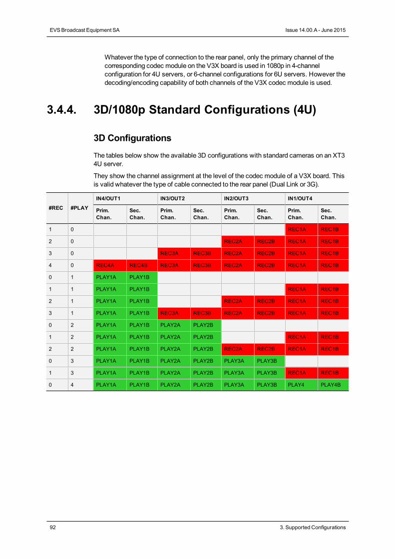
Whatever the type of connection to the rear panel, only the primary channel of thecorresponding codec module on the V3X board is used in 1080p in 4-channelconfiguration for 4U servers, or 6-channel configurations for 6U servers. However thedecoding/encoding capability of both channels of the V3X codec module is used.
3.4.4. 3D/1080p Standard Configurations (4U)
3D Configurations
The tables below show the available 3D configurations with standard cameras on an XT34U server.
They show the channel assignment at the level of the codec module of a V3X board. Thisis valid whatever the type of cable connected to the rear panel (Dual Link or 3G).
#REC #PLAY
IN4/OUT1 IN3/OUT2 IN2/OUT3 IN1/OUT4
Prim.Chan.
Sec.Chan.
Prim.Chan.
Sec.Chan.
Prim.Chan.
Sec.Chan.
Prim.Chan.
Sec.Chan.
1 0 REC1A REC1B
2 0 REC2A REC2B REC1A REC1B
3 0 REC3A REC3B REC2A REC2B REC1A REC1B
4 0 REC4A REC4B REC3A REC3B REC2A REC2B REC1A REC1B
0 1 PLAY1A PLAY1B
1 1 PLAY1A PLAY1B REC1A REC1B
2 1 PLAY1A PLAY1B REC2A REC2B REC1A REC1B
3 1 PLAY1A PLAY1B REC3A REC3B REC2A REC2B REC1A REC1B
0 2 PLAY1A PLAY1B PLAY2A PLAY2B
1 2 PLAY1A PLAY1B PLAY2A PLAY2B REC1A REC1B
2 2 PLAY1A PLAY1B PLAY2A PLAY2B REC2A REC2B REC1A REC1B
0 3 PLAY1A PLAY1B PLAY2A PLAY2B PLAY3A PLAY3B
1 3 PLAY1A PLAY1B PLAY2A PLAY2B PLAY3A PLAY3B REC1A REC1B
0 4 PLAY1A PLAY1B PLAY2A PLAY2B PLAY3A PLAY3B PLAY4 PLAY4B
92 3. Supported Configurations
EVSBroadcast Equipment SA Issue 14.00.A - June 2015
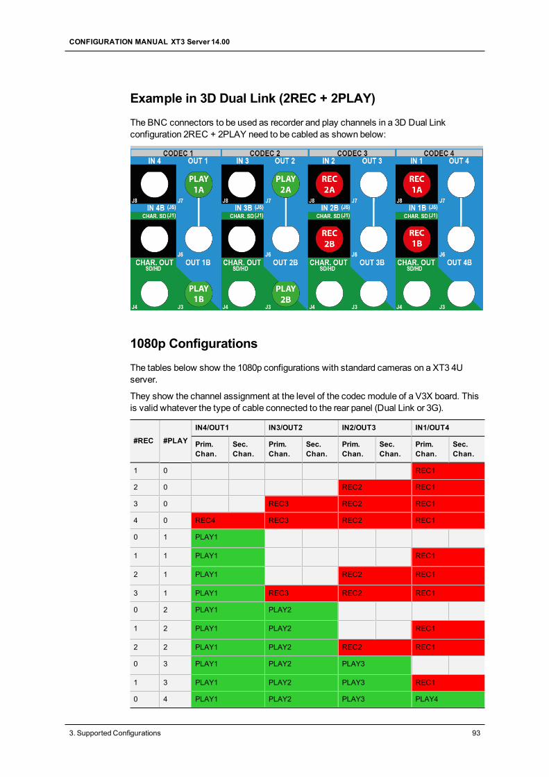
Example in 3D Dual Link (2REC + 2PLAY)
The BNC connectors to be used as recorder and play channels in a 3D Dual Linkconfiguration 2REC + 2PLAY need to be cabled as shown below:
1080p Configurations
The tables below show the 1080p configurations with standard cameras on a XT3 4Userver.
They show the channel assignment at the level of the codec module of a V3X board. Thisis valid whatever the type of cable connected to the rear panel (Dual Link or 3G).
#REC #PLAY
IN4/OUT1 IN3/OUT2 IN2/OUT3 IN1/OUT4
Prim.Chan.
Sec.Chan.
Prim.Chan.
Sec.Chan.
Prim.Chan.
Sec.Chan.
Prim.Chan.
Sec.Chan.
1 0 REC1
2 0 REC2 REC1
3 0 REC3 REC2 REC1
4 0 REC4 REC3 REC2 REC1
0 1 PLAY1
1 1 PLAY1 REC1
2 1 PLAY1 REC2 REC1
3 1 PLAY1 REC3 REC2 REC1
0 2 PLAY1 PLAY2
1 2 PLAY1 PLAY2 REC1
2 2 PLAY1 PLAY2 REC2 REC1
0 3 PLAY1 PLAY2 PLAY3
1 3 PLAY1 PLAY2 PLAY3 REC1
0 4 PLAY1 PLAY2 PLAY3 PLAY4
CONFIGURATION MANUAL XT3 Server 14.00
3. Supported Configurations 93
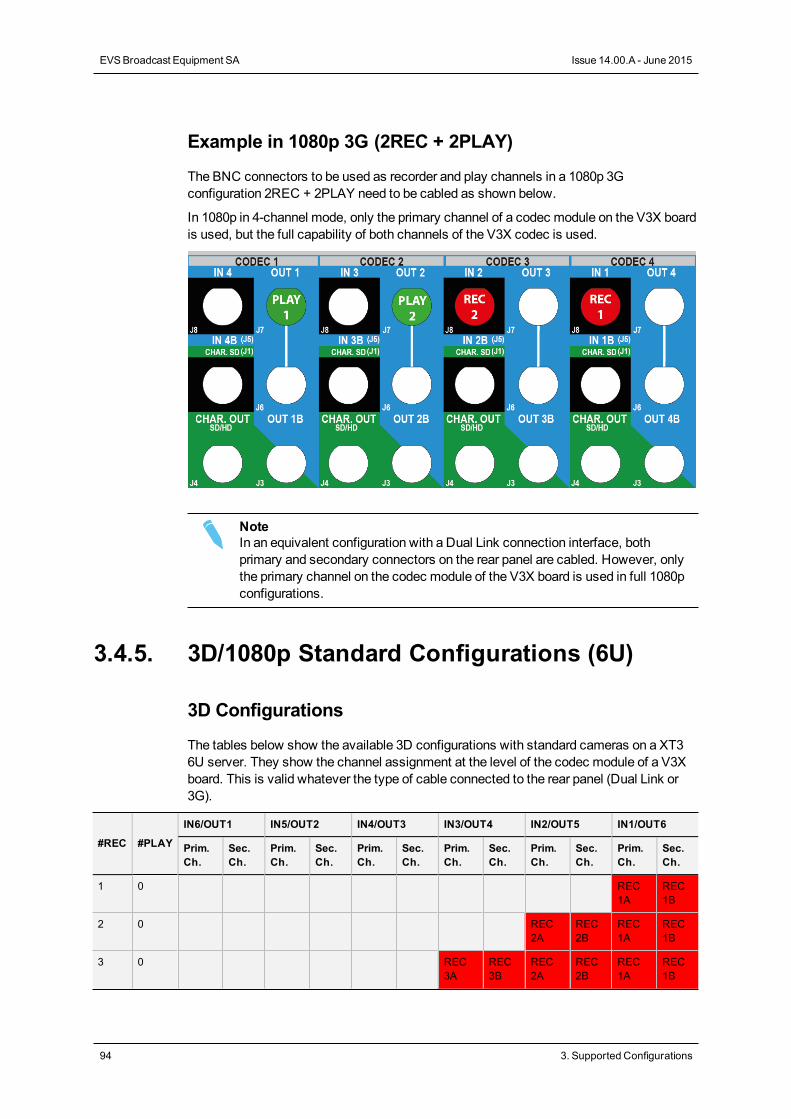
Example in 1080p 3G (2REC + 2PLAY)
The BNC connectors to be used as recorder and play channels in a 1080p 3Gconfiguration 2REC + 2PLAY need to be cabled as shown below.
In 1080p in 4-channel mode, only the primary channel of a codec module on the V3X boardis used, but the full capability of both channels of the V3X codec is used.
NoteIn an equivalent configuration with a Dual Link connection interface, bothprimary and secondary connectors on the rear panel are cabled. However, onlythe primary channel on the codec module of the V3X board is used in full 1080pconfigurations.
3.4.5. 3D/1080p Standard Configurations (6U)
3D Configurations
The tables below show the available 3D configurations with standard cameras on a XT36U server. They show the channel assignment at the level of the codec module of a V3Xboard. This is valid whatever the type of cable connected to the rear panel (Dual Link or3G).
#REC #PLAY
IN6/OUT1 IN5/OUT2 IN4/OUT3 IN3/OUT4 IN2/OUT5 IN1/OUT6
Prim.Ch.
Sec.Ch.
Prim.Ch.
Sec.Ch.
Prim.Ch.
Sec.Ch.
Prim.Ch.
Sec.Ch.
Prim.Ch.
Sec.Ch.
Prim.Ch.
Sec.Ch.
1 0 REC1A
REC1B
2 0 REC2A
REC2B
REC1A
REC1B
3 0 REC3A
REC3B
REC2A
REC2B
REC1A
REC1B
94 3. Supported Configurations
EVSBroadcast Equipment SA Issue 14.00.A - June 2015
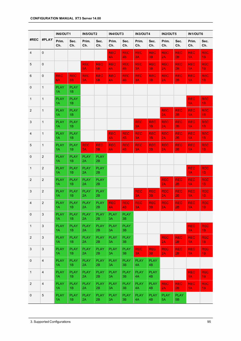
#REC #PLAY
IN6/OUT1 IN5/OUT2 IN4/OUT3 IN3/OUT4 IN2/OUT5 IN1/OUT6
Prim.Ch.
Sec.Ch.
Prim.Ch.
Sec.Ch.
Prim.Ch.
Sec.Ch.
Prim.Ch.
Sec.Ch.
Prim.Ch.
Sec.Ch.
Prim.Ch.
Sec.Ch.
4 0 REC4A
REC4B
REC3A
REC3B
REC2A
REC2B
REC1A
REC1B
5 0 REC5A
REC5B
REC4A
REC4B
REC3A
REC3B
REC2A
REC2B
REC1A
REC1B
6 0 REC6A
REC6B
REC5A
REC5B
REC4A
REC4B
REC3A
REC3B
REC2A
REC2B
REC1A
REC1B
0 1 PLAY1A
PLAY1B
1 1 PLAY1A
PLAY1B
REC1A
REC1B
2 1 PLAY1A
PLAY1B
REC2A
REC2B
REC1A
REC1B
3 1 PLAY1A
PLAY1B
REC3A
REC3B
REC2A
REC2B
REC1A
REC1B
4 1 PLAY1A
PLAY1B
REC4A
REC4B
REC3A
REC3B
REC2A
REC2B
REC1A
REC1B
5 1 PLAY1A
PLAY1B
REC5A
REC5B
REC4A
REC4B
REC3A
REC3B
REC2A
REC2B
REC1A
REC1B
0 2 PLAY1A
PLAY1B
PLAY2A
PLAY2B
1 2 PLAY1A
PLAY1B
PLAY2A
PLAY2B
REC1A
REC1B
2 2 PLAY1A
PLAY1B
PLAY2A
PLAY2B
REC2A
REC2B
REC1A
REC1B
3 2 PLAY1A
PLAY1B
PLAY2A
PLAY2B
REC3A
REC3B
REC2A
REC2B
REC1A
REC1B
4 2 PLAY1A
PLAY1B
PLAY2A
PLAY2B
REC4A
REC4B
REC3A
REC3B
REC2A
REC2B
REC1A
REC1B
0 3 PLAY1A
PLAY1B
PLAY2A
PLAY2B
PLAY3A
PLAY3B
1 3 PLAY1A
PLAY1B
PLAY2A
PLAY2B
PLAY3A
PLAY3B
REC1A
REC1B
2 3 PLAY1A
PLAY1B
PLAY2A
PLAY2B
PLAY3A
PLAY3B
REC2A
REC2B
REC1A
REC1B
3 3 PLAY1A
PLAY1B
PLAY2A
PLAY2B
PLAY3A
PLAY3B
REC3A
REC3B
REC2A
REC2B
REC1A
REC1B
0 4 PLAY1A
PLAY1B
PLAY2A
PLAY2B
PLAY3A
PLAY3B
PLAY4A
PLAY4B
1 4 PLAY1A
PLAY1B
PLAY2A
PLAY2B
PLAY3A
PLAY3B
PLAY4A
PLAY4B
REC1A
REC1B
2 4 PLAY1A
PLAY1B
PLAY2A
PLAY2B
PLAY3A
PLAY3B
PLAY4A
PLAY4B
REC2A
REC2B
REC1A
REC1B
0 5 PLAY1A
PLAY1B
PLAY2A
PLAY2B
PLAY3A
PLAY3B
PLAY4A
PLAY4B
PLAY5A
PLAY5B
CONFIGURATION MANUAL XT3 Server 14.00
3. Supported Configurations 95
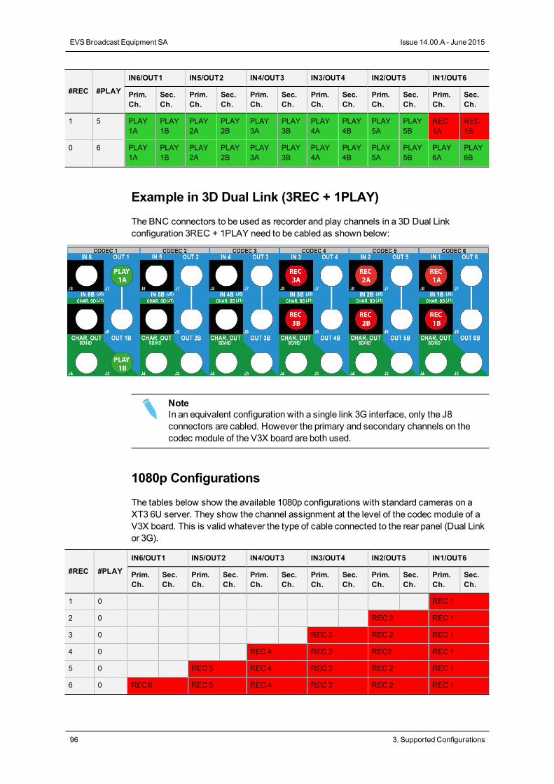
#REC #PLAY
IN6/OUT1 IN5/OUT2 IN4/OUT3 IN3/OUT4 IN2/OUT5 IN1/OUT6
Prim.Ch.
Sec.Ch.
Prim.Ch.
Sec.Ch.
Prim.Ch.
Sec.Ch.
Prim.Ch.
Sec.Ch.
Prim.Ch.
Sec.Ch.
Prim.Ch.
Sec.Ch.
1 5 PLAY1A
PLAY1B
PLAY2A
PLAY2B
PLAY3A
PLAY3B
PLAY4A
PLAY4B
PLAY5A
PLAY5B
REC1A
REC1B
0 6 PLAY1A
PLAY1B
PLAY2A
PLAY2B
PLAY3A
PLAY3B
PLAY4A
PLAY4B
PLAY5A
PLAY5B
PLAY6A
PLAY6B
Example in 3D Dual Link (3REC + 1PLAY)
The BNC connectors to be used as recorder and play channels in a 3D Dual Linkconfiguration 3REC + 1PLAY need to be cabled as shown below:
NoteIn an equivalent configuration with a single link 3G interface, only the J8connectors are cabled. However the primary and secondary channels on thecodec module of the V3X board are both used.
1080p Configurations
The tables below show the available 1080p configurations with standard cameras on aXT3 6U server. They show the channel assignment at the level of the codec module of aV3X board. This is valid whatever the type of cable connected to the rear panel (Dual Linkor 3G).
#REC #PLAY
IN6/OUT1 IN5/OUT2 IN4/OUT3 IN3/OUT4 IN2/OUT5 IN1/OUT6
Prim.Ch.
Sec.Ch.
Prim.Ch.
Sec.Ch.
Prim.Ch.
Sec.Ch.
Prim.Ch.
Sec.Ch.
Prim.Ch.
Sec.Ch.
Prim.Ch.
Sec.Ch.
1 0 REC 1
2 0 REC 2 REC 1
3 0 REC 3 REC 2 REC 1
4 0 REC 4 REC 3 REC2 REC 1
5 0 REC 5 REC 4 REC 3 REC 2 REC 1
6 0 REC6 REC 5 REC 4 REC 3 REC 2 REC 1
96 3. Supported Configurations
EVSBroadcast Equipment SA Issue 14.00.A - June 2015
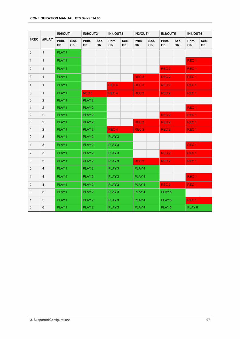
#REC #PLAY
IN6/OUT1 IN5/OUT2 IN4/OUT3 IN3/OUT4 IN2/OUT5 IN1/OUT6
Prim.Ch.
Sec.Ch.
Prim.Ch.
Sec.Ch.
Prim.Ch.
Sec.Ch.
Prim.Ch.
Sec.Ch.
Prim.Ch.
Sec.Ch.
Prim.Ch.
Sec.Ch.
0 1 PLAY1
1 1 PLAY1 REC 1
2 1 PLAY1 REC 2 REC 1
3 1 PLAY1 REC 3 REC 2 REC 1
4 1 PLAY1 REC 4 REC 3 REC 2 REC 1
5 1 PLAY1 REC 5 REC 4 REC 3 REC 2 REC 1
0 2 PLAY1 PLAY2
1 2 PLAY1 PLAY2 REC 1
2 2 PLAY1 PLAY2 REC 2 REC 1
3 2 PLAY1 PLAY2 REC 3 REC 2 REC 1
4 2 PLAY1 PLAY2 REC 4 REC 3 REC 2 REC 1
0 3 PLAY1 PLAY2 PLAY3
1 3 PLAY1 PLAY2 PLAY3 REC 1
2 3 PLAY1 PLAY2 PLAY3 REC 2 REC 1
3 3 PLAY1 PLAY2 PLAY3 REC 3 REC 2 REC 1
0 4 PLAY1 PLAY2 PLAY3 PLAY4
1 4 PLAY1 PLAY2 PLAY3 PLAY4 REC 1
2 4 PLAY1 PLAY2 PLAY3 PLAY4 REC 2 REC 1
0 5 PLAY1 PLAY2 PLAY3 PLAY4 PLAY5
1 5 PLAY1 PLAY2 PLAY3 PLAY4 PLAY5 REC 1
0 6 PLAY1 PLAY2 PLAY3 PLAY4 PLAY5 PLAY6
CONFIGURATION MANUAL XT3 Server 14.00
3. Supported Configurations 97
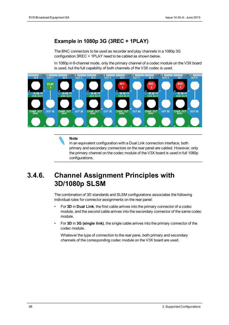
Example in 1080p 3G (3REC + 1PLAY)
The BNC connectors to be used as recorder and play channels in a 1080p 3Gconfiguration 3REC + 1PLAY need to be cabled as shown below.
In 1080p in 6-channel mode, only the primary channel of a codec module on the V3X boardis used, but the full capability of both channels of the V3X codec is used.
NoteIn an equivalent configuration with a Dual Link connection interface, bothprimary and secondary connectors on the rear panel are cabled. However, onlythe primary channel on the codec module of the V3X board is used in full 1080pconfigurations.
3.4.6. Channel Assignment Principles with3D/1080p SLSMThe combination of 3D standards and SLSM configurations associates the followingindividual rules for connector assignments on the rear panel:
• For 3D inDual Link, the first cable arrives into the primary connector of a codecmodule, and the second cable arrives into the secondary connector of the same codecmodule.
• For 3D in 3G (single link), the single cable arrives into the primary connector of thecodec module.
Whatever the type of connection to the rear pane, both primary and secondarychannels of the corresponding codec module on the V3X board are used.
98 3. Supported Configurations
EVSBroadcast Equipment SA Issue 14.00.A - June 2015
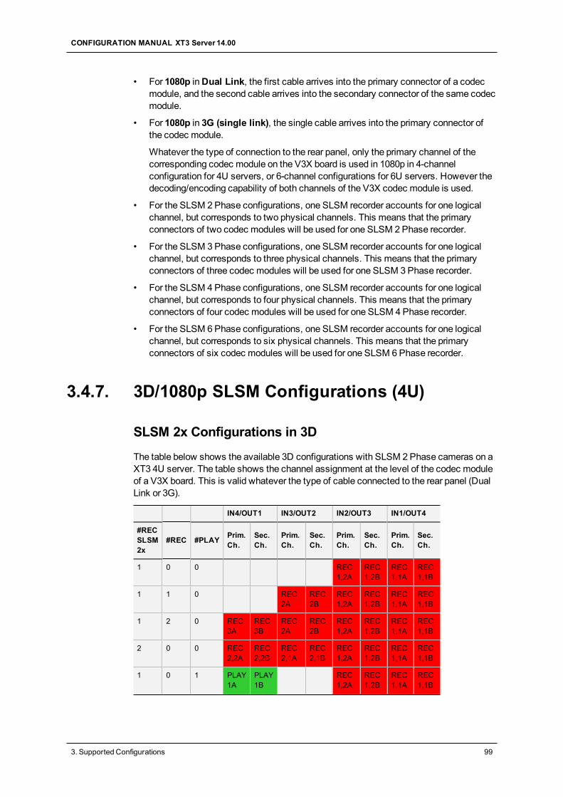
• For 1080p inDual Link, the first cable arrives into the primary connector of a codecmodule, and the second cable arrives into the secondary connector of the same codecmodule.
• For 1080p in 3G (single link), the single cable arrives into the primary connector ofthe codec module.
Whatever the type of connection to the rear panel, only the primary channel of thecorresponding codec module on the V3X board is used in 1080p in 4-channelconfiguration for 4U servers, or 6-channel configurations for 6U servers. However thedecoding/encoding capability of both channels of the V3X codec module is used.
• For the SLSM 2Phase configurations, one SLSM recorder accounts for one logicalchannel, but corresponds to two physical channels. This means that the primaryconnectors of two codec modules will be used for one SLSM 2Phase recorder.
• For the SLSM 3Phase configurations, one SLSM recorder accounts for one logicalchannel, but corresponds to three physical channels. This means that the primaryconnectors of three codec modules will be used for one SLSM 3Phase recorder.
• For the SLSM 4Phase configurations, one SLSM recorder accounts for one logicalchannel, but corresponds to four physical channels. This means that the primaryconnectors of four codec modules will be used for one SLSM 4Phase recorder.
• For the SLSM 6Phase configurations, one SLSM recorder accounts for one logicalchannel, but corresponds to six physical channels. This means that the primaryconnectors of six codec modules will be used for one SLSM 6Phase recorder.
3.4.7. 3D/1080p SLSM Configurations (4U)
SLSM 2x Configurations in 3D
The table below shows the available 3D configurations with SLSM 2Phase cameras on aXT3 4U server. The table shows the channel assignment at the level of the codec moduleof a V3X board. This is valid whatever the type of cable connected to the rear panel (DualLink or 3G).
IN4/OUT1 IN3/OUT2 IN2/OUT3 IN1/OUT4
#RECSLSM2x
#REC #PLAY Prim.Ch.
Sec.Ch.
Prim.Ch.
Sec.Ch.
Prim.Ch.
Sec.Ch.
Prim.Ch.
Sec.Ch.
1 0 0 REC1,2A
REC1,2B
REC1,1A
REC1,1B
1 1 0 REC2A
REC2B
REC1,2A
REC1,2B
REC1,1A
REC1,1B
1 2 0 REC3A
REC3B
REC2A
REC2B
REC1,2A
REC1,2B
REC1,1A
REC1,1B
2 0 0 REC2,2A
REC2,2B
REC2,1A
REC2,1B
REC1,2A
REC1,2B
REC1,1A
REC1,1B
1 0 1 PLAY1A
PLAY1B
REC1,2A
REC1,2B
REC1,1A
REC1,1B
CONFIGURATION MANUAL XT3 Server 14.00
3. Supported Configurations 99
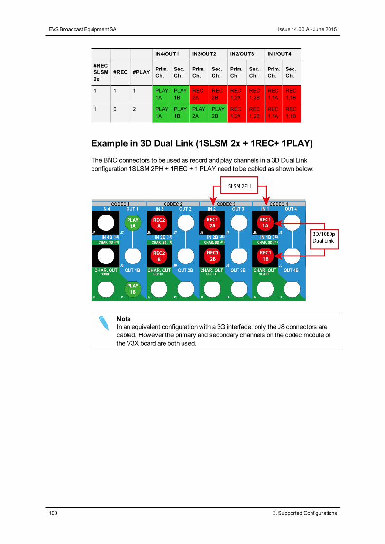
IN4/OUT1 IN3/OUT2 IN2/OUT3 IN1/OUT4
#RECSLSM2x
#REC #PLAY Prim.Ch.
Sec.Ch.
Prim.Ch.
Sec.Ch.
Prim.Ch.
Sec.Ch.
Prim.Ch.
Sec.Ch.
1 1 1 PLAY1A
PLAY1B
REC2A
REC2B
REC1,2A
REC1,2B
REC1,1A
REC1,1B
1 0 2 PLAY1A
PLAY1B
PLAY2A
PLAY2B
REC1,2A
REC1,2B
REC1,1A
REC1,1B
Example in 3D Dual Link (1SLSM 2x + 1REC+ 1PLAY)
The BNC connectors to be used as record and play channels in a 3D Dual Linkconfiguration 1SLSM 2PH + 1REC + 1 PLAY need to be cabled as shown below:
NoteIn an equivalent configuration with a 3G interface, only the J8 connectors arecabled. However the primary and secondary channels on the codec module ofthe V3X board are both used.
100 3. Supported Configurations
EVSBroadcast Equipment SA Issue 14.00.A - June 2015
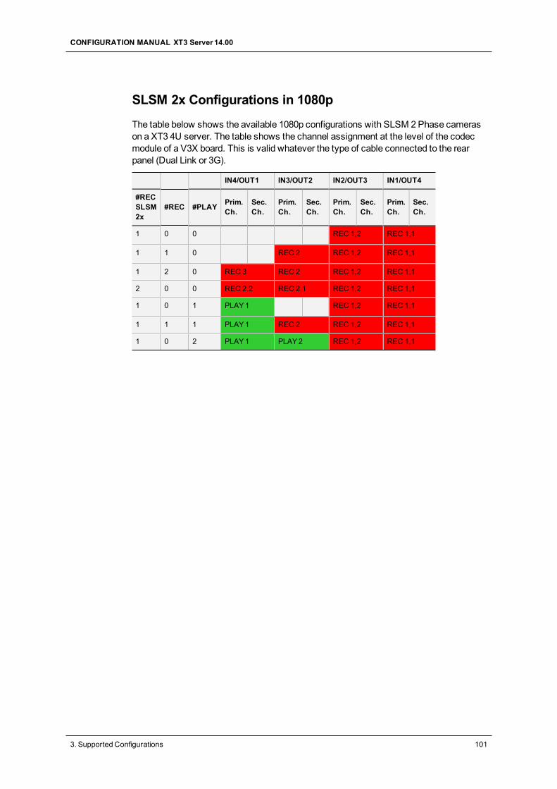
SLSM 2x Configurations in 1080p
The table below shows the available 1080p configurations with SLSM 2Phase camerason a XT3 4U server. The table shows the channel assignment at the level of the codecmodule of a V3X board. This is valid whatever the type of cable connected to the rearpanel (Dual Link or 3G).
IN4/OUT1 IN3/OUT2 IN2/OUT3 IN1/OUT4
#RECSLSM2x
#REC #PLAY Prim.Ch.
Sec.Ch.
Prim.Ch.
Sec.Ch.
Prim.Ch.
Sec.Ch.
Prim.Ch.
Sec.Ch.
1 0 0 REC 1,2 REC 1,1
1 1 0 REC 2 REC 1,2 REC 1,1
1 2 0 REC 3 REC 2 REC 1,2 REC 1,1
2 0 0 REC 2,2 REC 2,1 REC 1,2 REC 1,1
1 0 1 PLAY1 REC 1,2 REC 1,1
1 1 1 PLAY1 REC 2 REC 1,2 REC 1,1
1 0 2 PLAY1 PLAY2 REC 1,2 REC 1,1
CONFIGURATION MANUAL XT3 Server 14.00
3. Supported Configurations 101
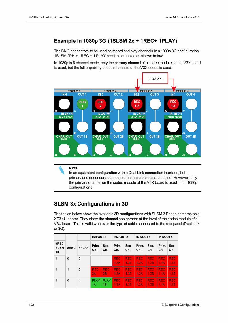
Example in 1080p 3G (1SLSM 2x + 1REC+ 1PLAY)
The BNC connectors to be used as record and play channels in a 1080p 3G configuration1SLSM 2PH + 1REC + 1 PLAY need to be cabled as shown below.
In 1080p in 6-channel mode, only the primary channel of a codec module on the V3X boardis used, but the full capability of both channels of the V3X codec is used.
NoteIn an equivalent configuration with a Dual Link connection interface, bothprimary and secondary connectors on the rear panel are cabled. However, onlythe primary channel on the codec module of the V3X board is used in full 1080pconfigurations.
SLSM 3x Configurations in 3D
The tables below show the available 3D configurations with SLSM 3Phase cameras on aXT3 4U server. They show the channel assignment at the level of the codec module of aV3X board. This is valid whatever the type of cable connected to the rear panel (Dual Linkor 3G).
IN4/OUT1 IN3/OUT2 IN2/OUT3 IN1/OUT4
#RECSLSM3x
#REC #PLAY Prim.Ch.
Sec.Ch.
Prim.Ch.
Sec.Ch.
Prim.Ch.
Sec.Ch.
Prim.Ch.
Sec.Ch.
1 0 0 REC1,3A
REC1,3B
REC1,2A
REC1,2B
REC1,1A
REC1,1B
1 1 0 REC2A
REC2B
REC1,3A
REC1,3B
REC1,2A
REC1,2B
REC1,1A
REC1,1B
1 0 1 PLAY1A
PLAY1B
REC1,3A
REC1,3B
REC1,2A
REC1,2B
REC1,1A
REC1,1B
102 3. Supported Configurations
EVSBroadcast Equipment SA Issue 14.00.A - June 2015
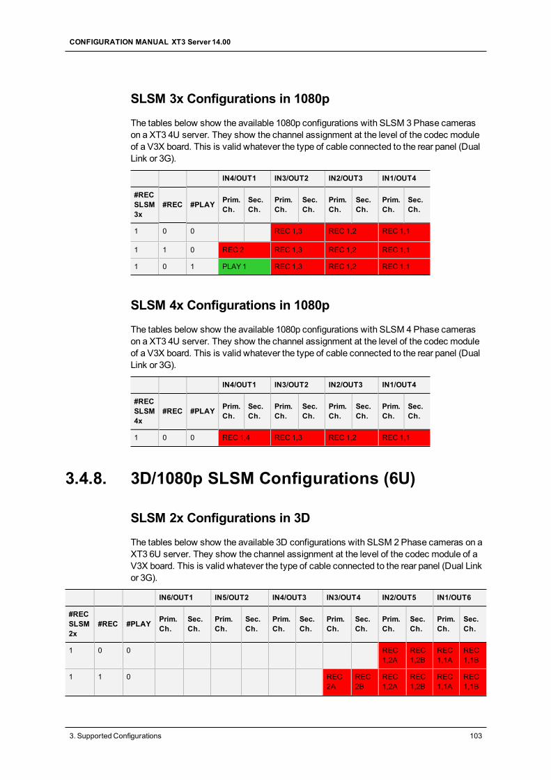
SLSM 3x Configurations in 1080p
The tables below show the available 1080p configurations with SLSM 3Phase camerason a XT3 4U server. They show the channel assignment at the level of the codec moduleof a V3X board. This is valid whatever the type of cable connected to the rear panel (DualLink or 3G).
IN4/OUT1 IN3/OUT2 IN2/OUT3 IN1/OUT4
#RECSLSM3x
#REC #PLAY Prim.Ch.
Sec.Ch.
Prim.Ch.
Sec.Ch.
Prim.Ch.
Sec.Ch.
Prim.Ch.
Sec.Ch.
1 0 0 REC 1,3 REC 1,2 REC 1,1
1 1 0 REC 2 REC 1,3 REC 1,2 REC 1,1
1 0 1 PLAY1 REC 1,3 REC 1,2 REC 1,1
SLSM 4x Configurations in 1080p
The tables below show the available 1080p configurations with SLSM 4Phase camerason a XT3 4U server. They show the channel assignment at the level of the codec moduleof a V3X board. This is valid whatever the type of cable connected to the rear panel (DualLink or 3G).
IN4/OUT1 IN3/OUT2 IN2/OUT3 IN1/OUT4
#RECSLSM4x
#REC #PLAY Prim.Ch.
Sec.Ch.
Prim.Ch.
Sec.Ch.
Prim.Ch.
Sec.Ch.
Prim.Ch.
Sec.Ch.
1 0 0 REC 1,4 REC 1,3 REC 1,2 REC 1,1
3.4.8. 3D/1080p SLSM Configurations (6U)
SLSM 2x Configurations in 3D
The tables below show the available 3D configurations with SLSM 2Phase cameras on aXT3 6U server. They show the channel assignment at the level of the codec module of aV3X board. This is valid whatever the type of cable connected to the rear panel (Dual Linkor 3G).
IN6/OUT1 IN5/OUT2 IN4/OUT3 IN3/OUT4 IN2/OUT5 IN1/OUT6
#RECSLSM2x
#REC #PLAY Prim.Ch.
Sec.Ch.
Prim.Ch.
Sec.Ch.
Prim.Ch.
Sec.Ch.
Prim.Ch.
Sec.Ch.
Prim.Ch.
Sec.Ch.
Prim.Ch.
Sec.Ch.
1 0 0 REC1,2A
REC1,2B
REC1,1A
REC1,1B
1 1 0 REC2A
REC2B
REC1,2A
REC1,2B
REC1,1A
REC1,1B
CONFIGURATION MANUAL XT3 Server 14.00
3. Supported Configurations 103
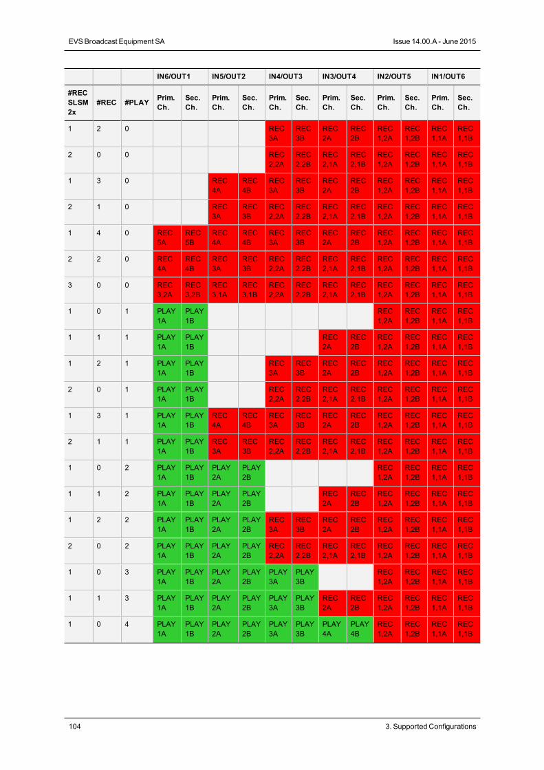
IN6/OUT1 IN5/OUT2 IN4/OUT3 IN3/OUT4 IN2/OUT5 IN1/OUT6
#RECSLSM2x
#REC #PLAY Prim.Ch.
Sec.Ch.
Prim.Ch.
Sec.Ch.
Prim.Ch.
Sec.Ch.
Prim.Ch.
Sec.Ch.
Prim.Ch.
Sec.Ch.
Prim.Ch.
Sec.Ch.
1 2 0 REC3A
REC3B
REC2A
REC2B
REC1,2A
REC1,2B
REC1,1A
REC1,1B
2 0 0 REC2,2A
REC2,2B
REC2,1A
REC2,1B
REC1,2A
REC1,2B
REC1,1A
REC1,1B
1 3 0 REC4A
REC4B
REC3A
REC3B
REC2A
REC2B
REC1,2A
REC1,2B
REC1,1A
REC1,1B
2 1 0 REC3A
REC3B
REC2,2A
REC2,2B
REC2,1A
REC2,1B
REC1,2A
REC1,2B
REC1,1A
REC1,1B
1 4 0 REC5A
REC5B
REC4A
REC4B
REC3A
REC3B
REC2A
REC2B
REC1,2A
REC1,2B
REC1,1A
REC1,1B
2 2 0 REC4A
REC4B
REC3A
REC3B
REC2,2A
REC2,2B
REC2,1A
REC2,1B
REC1,2A
REC1,2B
REC1,1A
REC1,1B
3 0 0 REC3,2A
REC3,2B
REC3,1A
REC3,1B
REC2,2A
REC2,2B
REC2,1A
REC2,1B
REC1,2A
REC1,2B
REC1,1A
REC1,1B
1 0 1 PLAY1A
PLAY1B
REC1,2A
REC1,2B
REC1,1A
REC1,1B
1 1 1 PLAY1A
PLAY1B
REC2A
REC2B
REC1,2A
REC1,2B
REC1,1A
REC1,1B
1 2 1 PLAY1A
PLAY1B
REC3A
REC3B
REC2A
REC2B
REC1,2A
REC1,2B
REC1,1A
REC1,1B
2 0 1 PLAY1A
PLAY1B
REC2,2A
REC2,2B
REC2,1A
REC2,1B
REC1,2A
REC1,2B
REC1,1A
REC1,1B
1 3 1 PLAY1A
PLAY1B
REC4A
REC4B
REC3A
REC3B
REC2A
REC2B
REC1,2A
REC1,2B
REC1,1A
REC1,1B
2 1 1 PLAY1A
PLAY1B
REC3A
REC3B
REC2,2A
REC2,2B
REC2,1A
REC2,1B
REC1,2A
REC1,2B
REC1,1A
REC1,1B
1 0 2 PLAY1A
PLAY1B
PLAY2A
PLAY2B
REC1,2A
REC1,2B
REC1,1A
REC1,1B
1 1 2 PLAY1A
PLAY1B
PLAY2A
PLAY2B
REC2A
REC2B
REC1,2A
REC1,2B
REC1,1A
REC1,1B
1 2 2 PLAY1A
PLAY1B
PLAY2A
PLAY2B
REC3A
REC3B
REC2A
REC2B
REC1,2A
REC1,2B
REC1,1A
REC1,1B
2 0 2 PLAY1A
PLAY1B
PLAY2A
PLAY2B
REC2,2A
REC2,2B
REC2,1A
REC2,1B
REC1,2A
REC1,2B
REC1,1A
REC1,1B
1 0 3 PLAY1A
PLAY1B
PLAY2A
PLAY2B
PLAY3A
PLAY3B
REC1,2A
REC1,2B
REC1,1A
REC1,1B
1 1 3 PLAY1A
PLAY1B
PLAY2A
PLAY2B
PLAY3A
PLAY3B
REC2A
REC2B
REC1,2A
REC1,2B
REC1,1A
REC1,1B
1 0 4 PLAY1A
PLAY1B
PLAY2A
PLAY2B
PLAY3A
PLAY3B
PLAY4A
PLAY4B
REC1,2A
REC1,2B
REC1,1A
REC1,1B
104 3. Supported Configurations
EVSBroadcast Equipment SA Issue 14.00.A - June 2015
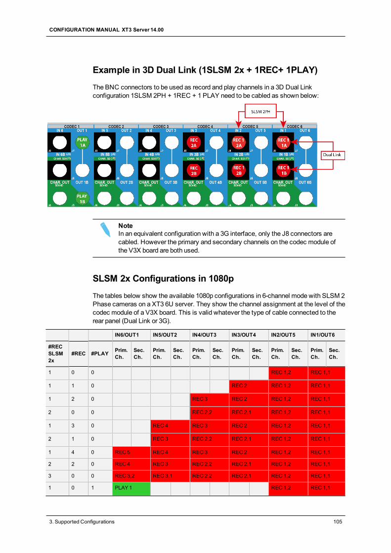
Example in 3D Dual Link (1SLSM 2x + 1REC+ 1PLAY)
The BNC connectors to be used as record and play channels in a 3D Dual Linkconfiguration 1SLSM 2PH + 1REC + 1 PLAY need to be cabled as shown below:
NoteIn an equivalent configuration with a 3G interface, only the J8 connectors arecabled. However the primary and secondary channels on the codec module ofthe V3X board are both used.
SLSM 2x Configurations in 1080p
The tables below show the available 1080p configurations in 6-channel mode with SLSM 2Phase cameras on a XT3 6U server. They show the channel assignment at the level of thecodec module of a V3X board. This is valid whatever the type of cable connected to therear panel (Dual Link or 3G).
IN6/OUT1 IN5/OUT2 IN4/OUT3 IN3/OUT4 IN2/OUT5 IN1/OUT6
#RECSLSM2x
#REC #PLAY Prim.Ch.
Sec.Ch.
Prim.Ch.
Sec.Ch.
Prim.Ch.
Sec.Ch.
Prim.Ch.
Sec.Ch.
Prim.Ch.
Sec.Ch.
Prim.Ch.
Sec.Ch.
1 0 0 REC 1,2 REC 1,1
1 1 0 REC 2 REC 1,2 REC 1,1
1 2 0 REC 3 REC 2 REC 1,2 REC 1,1
2 0 0 REC 2,2 REC 2,1 REC 1,2 REC 1,1
1 3 0 REC 4 REC 3 REC 2 REC 1,2 REC 1,1
2 1 0 REC 3 REC 2,2 REC 2,1 REC 1,2 REC 1,1
1 4 0 REC 5 REC 4 REC 3 REC 2 REC 1,2 REC 1,1
2 2 0 REC 4 REC 3 REC 2,2 REC 2,1 REC 1,2 REC 1,1
3 0 0 REC 3,2 REC 3,1 REC 2,2 REC 2,1 REC 1,2 REC 1,1
1 0 1 PLAY1 REC 1,2 REC 1,1
CONFIGURATION MANUAL XT3 Server 14.00
3. Supported Configurations 105
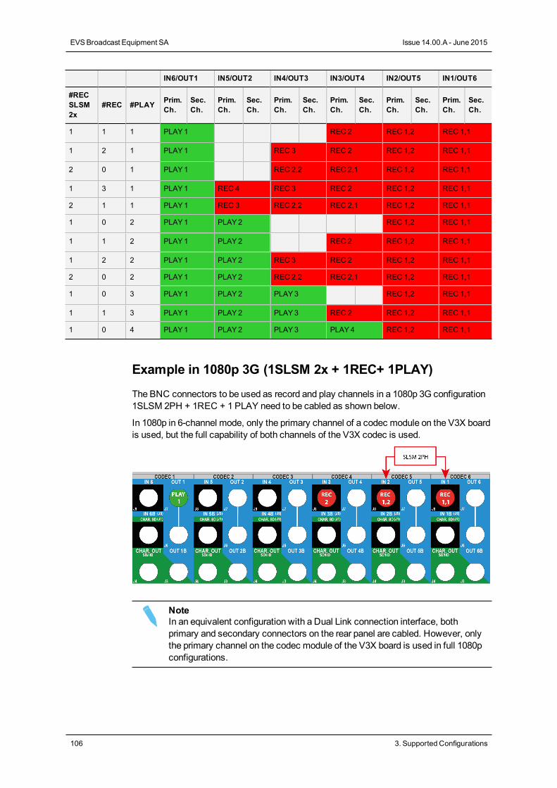
IN6/OUT1 IN5/OUT2 IN4/OUT3 IN3/OUT4 IN2/OUT5 IN1/OUT6
#RECSLSM2x
#REC #PLAY Prim.Ch.
Sec.Ch.
Prim.Ch.
Sec.Ch.
Prim.Ch.
Sec.Ch.
Prim.Ch.
Sec.Ch.
Prim.Ch.
Sec.Ch.
Prim.Ch.
Sec.Ch.
1 1 1 PLAY1 REC 2 REC 1,2 REC 1,1
1 2 1 PLAY1 REC 3 REC 2 REC 1,2 REC 1,1
2 0 1 PLAY1 REC 2,2 REC 2,1 REC 1,2 REC 1,1
1 3 1 PLAY1 REC 4 REC 3 REC 2 REC 1,2 REC 1,1
2 1 1 PLAY1 REC 3 REC 2,2 REC 2,1 REC 1,2 REC 1,1
1 0 2 PLAY1 PLAY2 REC 1,2 REC 1,1
1 1 2 PLAY1 PLAY2 REC 2 REC 1,2 REC 1,1
1 2 2 PLAY1 PLAY2 REC 3 REC 2 REC 1,2 REC 1,1
2 0 2 PLAY1 PLAY2 REC 2,2 REC 2,1 REC 1,2 REC 1,1
1 0 3 PLAY1 PLAY2 PLAY3 REC 1,2 REC 1,1
1 1 3 PLAY1 PLAY2 PLAY3 REC 2 REC 1,2 REC 1,1
1 0 4 PLAY1 PLAY2 PLAY3 PLAY4 REC 1,2 REC 1,1
Example in 1080p 3G (1SLSM 2x + 1REC+ 1PLAY)
The BNC connectors to be used as record and play channels in a 1080p 3G configuration1SLSM 2PH + 1REC + 1 PLAY need to be cabled as shown below.
In 1080p in 6-channel mode, only the primary channel of a codec module on the V3X boardis used, but the full capability of both channels of the V3X codec is used.
NoteIn an equivalent configuration with a Dual Link connection interface, bothprimary and secondary connectors on the rear panel are cabled. However, onlythe primary channel on the codec module of the V3X board is used in full 1080pconfigurations.
106 3. Supported Configurations
EVSBroadcast Equipment SA Issue 14.00.A - June 2015
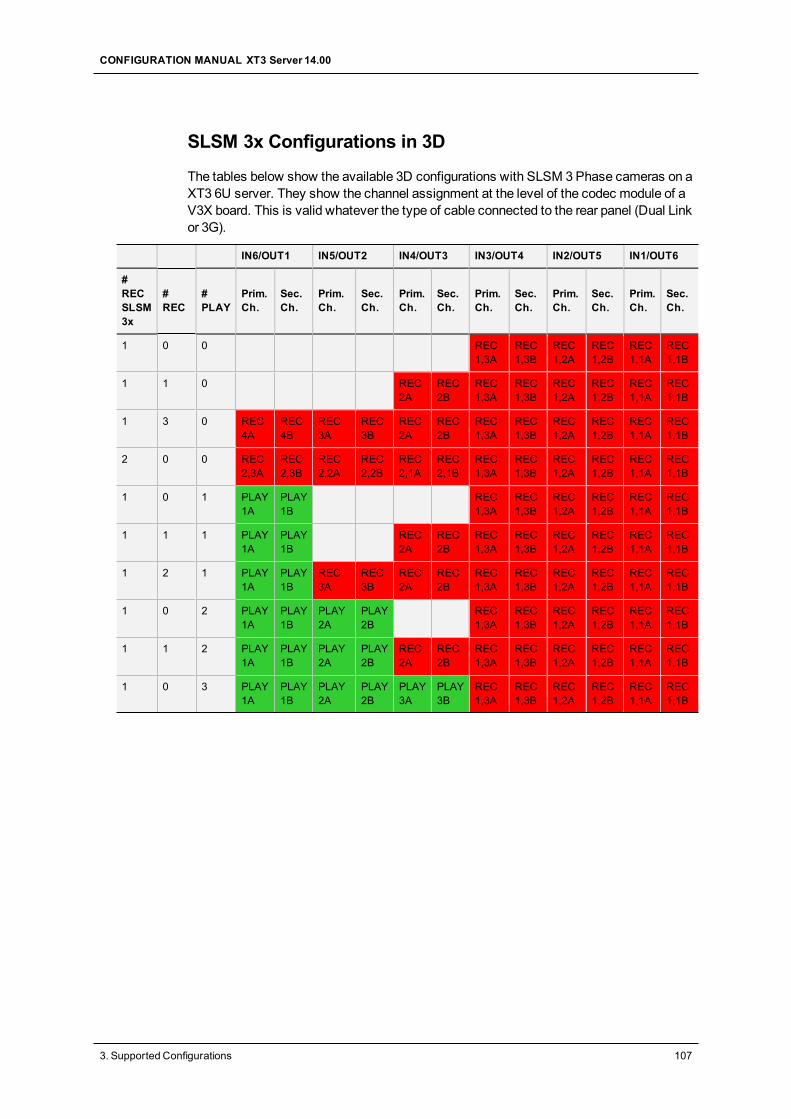
SLSM 3x Configurations in 3D
The tables below show the available 3D configurations with SLSM 3Phase cameras on aXT3 6U server. They show the channel assignment at the level of the codec module of aV3X board. This is valid whatever the type of cable connected to the rear panel (Dual Linkor 3G).
IN6/OUT1 IN5/OUT2 IN4/OUT3 IN3/OUT4 IN2/OUT5 IN1/OUT6
#RECSLSM3x
#REC
#PLAY
Prim.Ch.
Sec.Ch.
Prim.Ch.
Sec.Ch.
Prim.Ch.
Sec.Ch.
Prim.Ch.
Sec.Ch.
Prim.Ch.
Sec.Ch.
Prim.Ch.
Sec.Ch.
1 0 0 REC1,3A
REC1,3B
REC1,2A
REC1,2B
REC1,1A
REC1,1B
1 1 0 REC2A
REC2B
REC1,3A
REC1,3B
REC1,2A
REC1,2B
REC1,1A
REC1,1B
1 3 0 REC4A
REC4B
REC3A
REC3B
REC2A
REC2B
REC1,3A
REC1,3B
REC1,2A
REC1,2B
REC1,1A
REC1,1B
2 0 0 REC2,3A
REC2,3B
REC2,2A
REC2,2B
REC2,1A
REC2,1B
REC1,3A
REC1,3B
REC1,2A
REC1,2B
REC1,1A
REC1,1B
1 0 1 PLAY1A
PLAY1B
REC1,3A
REC1,3B
REC1,2A
REC1,2B
REC1,1A
REC1,1B
1 1 1 PLAY1A
PLAY1B
REC2A
REC2B
REC1,3A
REC1,3B
REC1,2A
REC1,2B
REC1,1A
REC1,1B
1 2 1 PLAY1A
PLAY1B
REC3A
REC3B
REC2A
REC2B
REC1,3A
REC1,3B
REC1,2A
REC1,2B
REC1,1A
REC1,1B
1 0 2 PLAY1A
PLAY1B
PLAY2A
PLAY2B
REC1,3A
REC1,3B
REC1,2A
REC1,2B
REC1,1A
REC1,1B
1 1 2 PLAY1A
PLAY1B
PLAY2A
PLAY2B
REC2A
REC2B
REC1,3A
REC1,3B
REC1,2A
REC1,2B
REC1,1A
REC1,1B
1 0 3 PLAY1A
PLAY1B
PLAY2A
PLAY2B
PLAY3A
PLAY3B
REC1,3A
REC1,3B
REC1,2A
REC1,2B
REC1,1A
REC1,1B
CONFIGURATION MANUAL XT3 Server 14.00
3. Supported Configurations 107
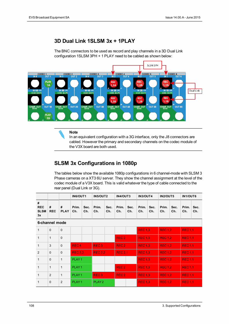
3D Dual Link 1SLSM 3x + 1PLAY
The BNC connectors to be used as record and play channels in a 3D Dual Linkconfiguration 1SLSM 3PH + 1 PLAY need to be cabled as shown below:
NoteIn an equivalent configuration with a 3G interface, only the J8 connectors arecabled. However the primary and secondary channels on the codec module ofthe V3X board are both used.
SLSM 3x Configurations in 1080p
The tables below show the available 1080p configurations in 6 channel-mode with SLSM 3Phase cameras on a XT3 6U server. They show the channel assignment at the level of thecodec module of a V3X board. This is valid whatever the type of cable connected to therear panel (Dual Link or 3G).
IN6/OUT1 IN5/OUT2 IN4/OUT3 IN3/OUT4 IN2/OUT5 IN1/OUT6
#RECSLSM3x
#REC
#PLAY
Prim.Ch.
Sec.Ch.
Prim.Ch.
Sec.Ch.
Prim.Ch.
Sec.Ch.
Prim.Ch.
Sec.Ch.
Prim.Ch.
Sec.Ch.
Prim.Ch.
Sec.Ch.
6-channel mode
1 0 0 REC 1,3 REC 1,2 REC 1,1
1 1 0 REC 2 REC 1,3 REC 1,2 REC 1,1
1 3 0 REC 4 REC 3 REC 2 REC 1,3 REC 1,2 REC 1,1
2 0 0 REC 2,3 REC 2,2 REC 2,1 REC 1,3 REC 1,2 REC 1,1
1 0 1 PLAY1 REC 1,3 REC 1,2 REC 1,1
1 1 1 PLAY1 REC 2 REC 1,3 REC 1,2 REC 1,1
1 2 1 PLAY1 REC 3 REC 2 REC 1,3 REC 1,2 REC 1,1
1 0 2 PLAY1 PLAY2 REC 1,3 REC 1,2 REC 1,1
108 3. Supported Configurations
EVSBroadcast Equipment SA Issue 14.00.A - June 2015
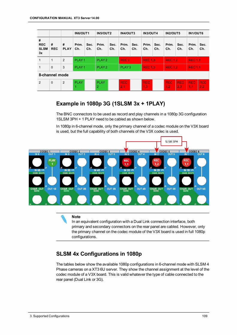
IN6/OUT1 IN5/OUT2 IN4/OUT3 IN3/OUT4 IN2/OUT5 IN1/OUT6
#RECSLSM3x
#REC
#PLAY
Prim.Ch.
Sec.Ch.
Prim.Ch.
Sec.Ch.
Prim.Ch.
Sec.Ch.
Prim.Ch.
Sec.Ch.
Prim.Ch.
Sec.Ch.
Prim.Ch.
Sec.Ch.
1 1 2 PLAY1 PLAY2 REC 2 REC 1,3 REC 1,2 REC 1,1
1 0 3 PLAY1 PLAY2 PLAY3 REC 1,3 REC 1,2 REC 1,1
8-channel mode
2 0 2 PLAY1
PLAY2
REC2,1
REC1,3
REC1,2
REC2,3
REC1,1
REC2,2
Example in 1080p 3G (1SLSM 3x + 1PLAY)
The BNC connectors to be used as record and play channels in a 1080p 3G configuration1SLSM 3PH + 1 PLAY need to be cabled as shown below.
In 1080p in 6-channel mode, only the primary channel of a codec module on the V3X boardis used, but the full capability of both channels of the V3X codec is used.
NoteIn an equivalent configuration with a Dual Link connection interface, bothprimary and secondary connectors on the rear panel are cabled. However, onlythe primary channel on the codec module of the V3X board is used in full 1080pconfigurations.
SLSM 4x Configurations in 1080p
The tables below show the available 1080p configurations in 6-channel mode with SLSM 4Phase cameras on a XT3 6U server. They show the channel assignment at the level of thecodec module of a V3X board. This is valid whatever the type of cable connected to therear panel (Dual Link or 3G).
CONFIGURATION MANUAL XT3 Server 14.00
3. Supported Configurations 109
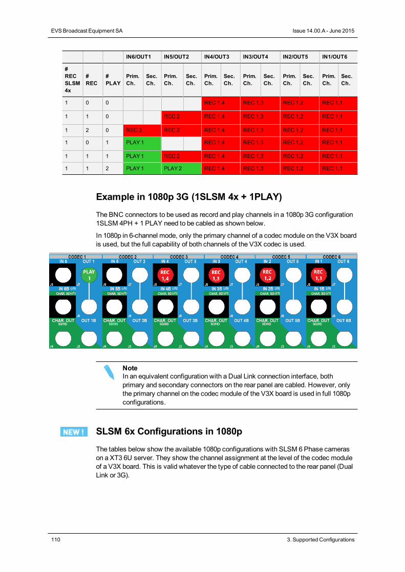
IN6/OUT1 IN5/OUT2 IN4/OUT3 IN3/OUT4 IN2/OUT5 IN1/OUT6
#RECSLSM4x
#REC
#PLAY
Prim.Ch.
Sec.Ch.
Prim.Ch.
Sec.Ch.
Prim.Ch.
Sec.Ch.
Prim.Ch.
Sec.Ch.
Prim.Ch.
Sec.Ch.
Prim.Ch.
Sec.Ch.
1 0 0 REC 1,4 REC 1,3 REC 1,2 REC 1,1
1 1 0 REC 2 REC 1,4 REC 1,3 REC 1,2 REC 1,1
1 2 0 REC 3 REC 2 REC 1,4 REC 1,3 REC 1,2 REC 1,1
1 0 1 PLAY1 REC 1,4 REC 1,3 REC 1,2 REC 1,1
1 1 1 PLAY1 REC 2 REC 1,4 REC 1,3 REC 1,2 REC 1,1
1 1 2 PLAY1 PLAY2 REC 1,4 REC 1,3 REC 1,2 REC 1,1
Example in 1080p 3G (1SLSM 4x + 1PLAY)
The BNC connectors to be used as record and play channels in a 1080p 3G configuration1SLSM 4PH + 1 PLAY need to be cabled as shown below.
In 1080p in 6-channel mode, only the primary channel of a codec module on the V3X boardis used, but the full capability of both channels of the V3X codec is used.
NoteIn an equivalent configuration with a Dual Link connection interface, bothprimary and secondary connectors on the rear panel are cabled. However, onlythe primary channel on the codec module of the V3X board is used in full 1080pconfigurations.
SLSM 6x Configurations in 1080p
The tables below show the available 1080p configurations with SLSM 6Phase camerason a XT3 6U server. They show the channel assignment at the level of the codec moduleof a V3X board. This is valid whatever the type of cable connected to the rear panel (DualLink or 3G).
110 3. Supported Configurations
EVSBroadcast Equipment SA Issue 14.00.A - June 2015
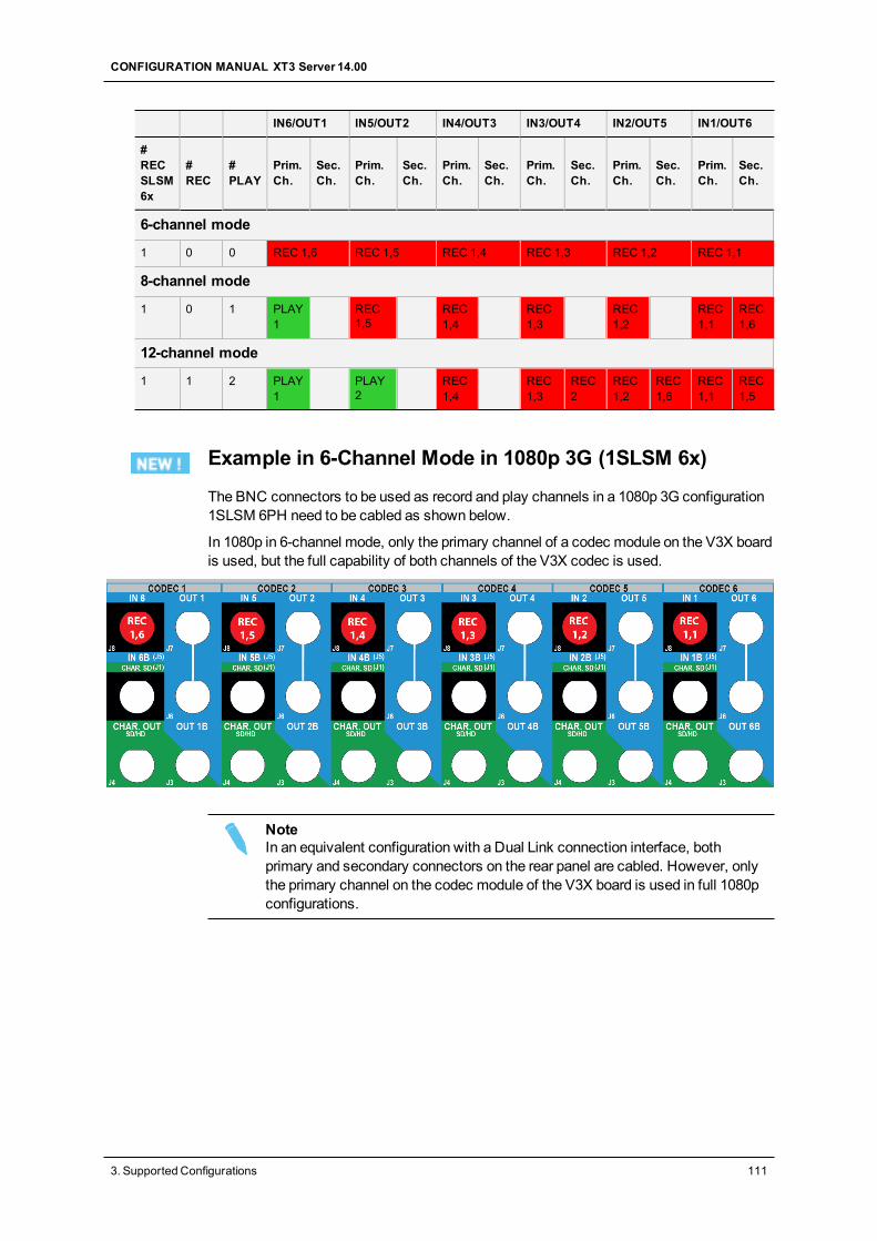
IN6/OUT1 IN5/OUT2 IN4/OUT3 IN3/OUT4 IN2/OUT5 IN1/OUT6
#RECSLSM6x
#REC
#PLAY
Prim.Ch.
Sec.Ch.
Prim.Ch.
Sec.Ch.
Prim.Ch.
Sec.Ch.
Prim.Ch.
Sec.Ch.
Prim.Ch.
Sec.Ch.
Prim.Ch.
Sec.Ch.
6-channel mode
1 0 0 REC 1,6 REC 1,5 REC 1,4 REC 1,3 REC 1,2 REC 1,1
8-channel mode
1 0 1 PLAY1
REC1,5
REC1,4
REC1,3
REC1,2
REC1,1
REC1,6
12-channel mode
1 1 2 PLAY1
PLAY2
REC1,4
REC1,3
REC2
REC1,2
REC1,6
REC1,1
REC1,5
Example in 6-Channel Mode in 1080p 3G (1SLSM 6x)
The BNC connectors to be used as record and play channels in a 1080p 3G configuration1SLSM 6PH need to be cabled as shown below.
In 1080p in 6-channel mode, only the primary channel of a codec module on the V3X boardis used, but the full capability of both channels of the V3X codec is used.
NoteIn an equivalent configuration with a Dual Link connection interface, bothprimary and secondary connectors on the rear panel are cabled. However, onlythe primary channel on the codec module of the V3X board is used in full 1080pconfigurations.
CONFIGURATION MANUAL XT3 Server 14.00
3. Supported Configurations 111
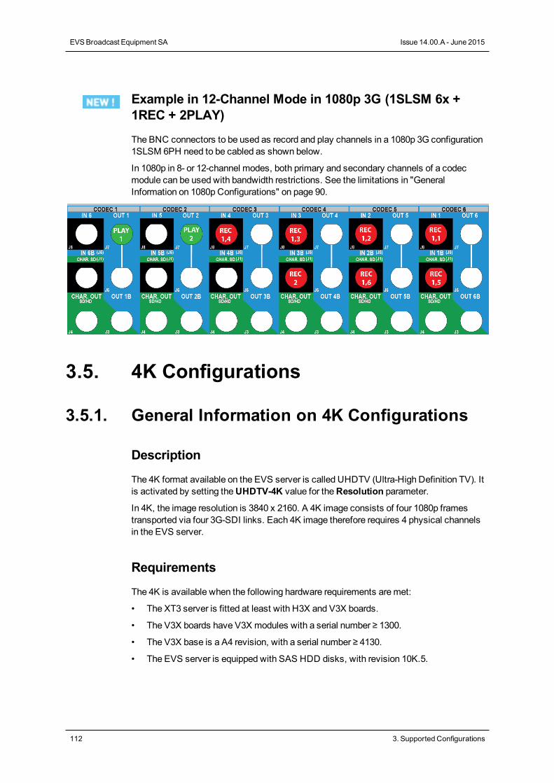
Example in 12-Channel Mode in 1080p 3G (1SLSM 6x +1REC + 2PLAY)
The BNC connectors to be used as record and play channels in a 1080p 3G configuration1SLSM 6PH need to be cabled as shown below.
In 1080p in 8- or 12-channel modes, both primary and secondary channels of a codecmodule can be used with bandwidth restrictions. See the limitations in "GeneralInformation on 1080p Configurations" on page 90.
3.5. 4K Configurations
3.5.1. General Information on 4K Configurations
Description
The 4K format available on the EVS server is called UHDTV (Ultra-High Definition TV). Itis activated by setting theUHDTV-4K value for theResolution parameter.
In 4K, the image resolution is 3840 x 2160. A 4K image consists of four 1080p framestransported via four 3G-SDI links. Each 4K image therefore requires 4 physical channelsin the EVS server.
Requirements
The 4K is available when the following hardware requirements aremet:
• The XT3 server is fitted at least with H3X and V3X boards.
• The V3X boards have V3X modules with a serial number ≥ 1300.
• The V3X base is a A4 revision, with a serial number ≥ 4130.
• The EVS server is equipped with SAS HDD disks, with revision 10K.5.
112 3. Supported Configurations
EVSBroadcast Equipment SA Issue 14.00.A - June 2015
The 4K is available when the following software requirements aremet:
• The license code 27 is granted on the EVS server.
• TheResolution parameter is set toUHDTV-4K.
See section "Video and Reference Settings" on page 131.
• The Intra Codec parameter is set toDNxHD (forced value).
See section "Codec Settings" on page 135.
• The 3G/Dual parameter is set to a 3G value.
TheNo value is automatically excluded.
See section "Base Settings" on page 153.
Limitations
Codec Limitations
• 4K can only be used with the DNxHD Intra codecs.
• 4K cannot be used with LongGOP or Proxy codecs.
Configuration Limitations
• 4K does not support 3D configurations.
• 4K supports theMix on one channel feature with limitations.
Audio Limitations
• 4K does not support 16 audio tracks.
Operational Limitations
The following features are NOT available with 4K:
• EditRec
• Offside Line (internal or external)
• CAMMapping
• Internal Loopmode
• Replace External Loop
• Split Screen feature
• Paint Target feature
CONFIGURATION MANUAL XT3 Server 14.00
3. Supported Configurations 113
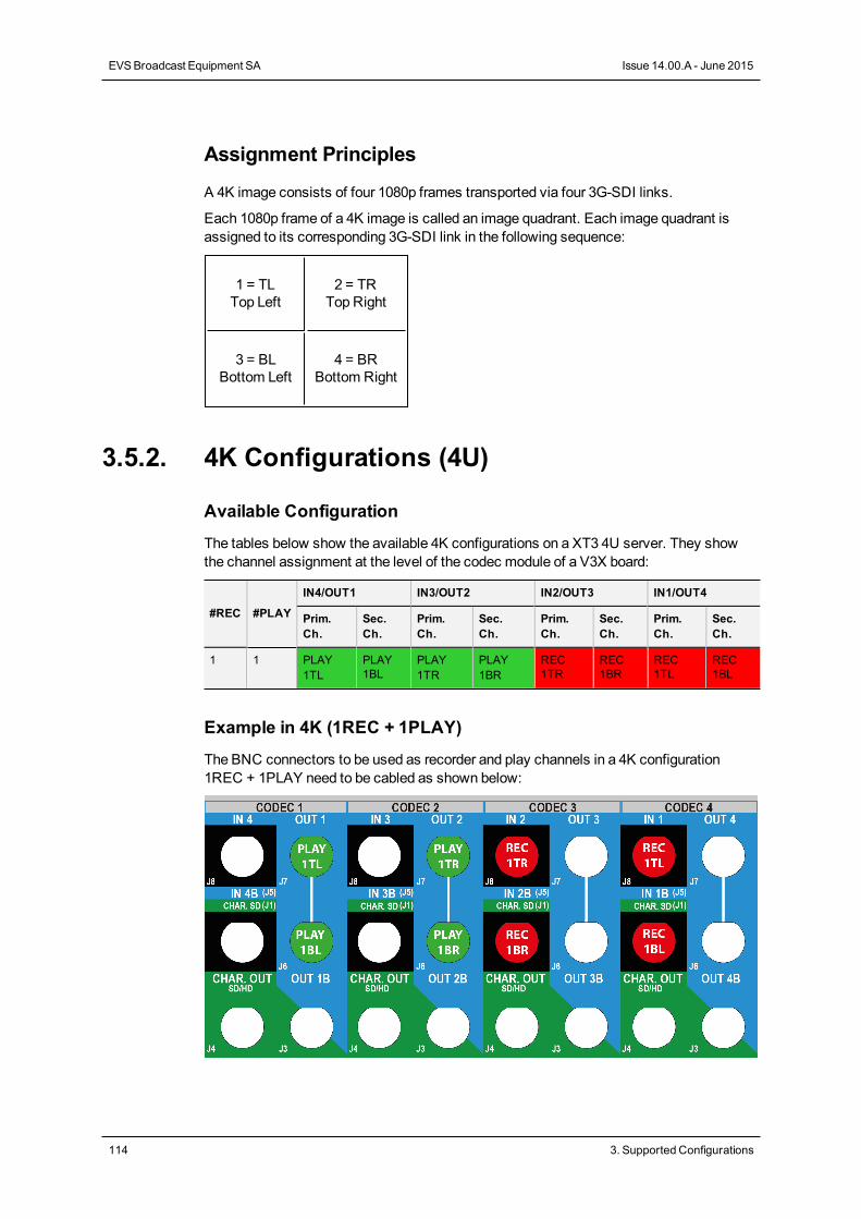
Assignment Principles
A 4K image consists of four 1080p frames transported via four 3G-SDI links.
Each 1080p frame of a 4K image is called an image quadrant. Each image quadrant isassigned to its corresponding 3G-SDI link in the following sequence:
1 = TLTop Left
2 = TRTop Right
3 = BLBottom Left
4 = BRBottom Right
3.5.2. 4K Configurations (4U)
Available Configuration
The tables below show the available 4K configurations on a XT3 4U server. They showthe channel assignment at the level of the codec module of a V3X board:
#REC #PLAY
IN4/OUT1 IN3/OUT2 IN2/OUT3 IN1/OUT4
Prim.Ch.
Sec.Ch.
Prim.Ch.
Sec.Ch.
Prim.Ch.
Sec.Ch.
Prim.Ch.
Sec.Ch.
1 1 PLAY1TL
PLAY1BL
PLAY1TR
PLAY1BR
REC1TR
REC1BR
REC1TL
REC1BL
Example in 4K (1REC + 1PLAY)
The BNC connectors to be used as recorder and play channels in a 4K configuration1REC + 1PLAY need to be cabled as shown below:
114 3. Supported Configurations
EVSBroadcast Equipment SA Issue 14.00.A - June 2015
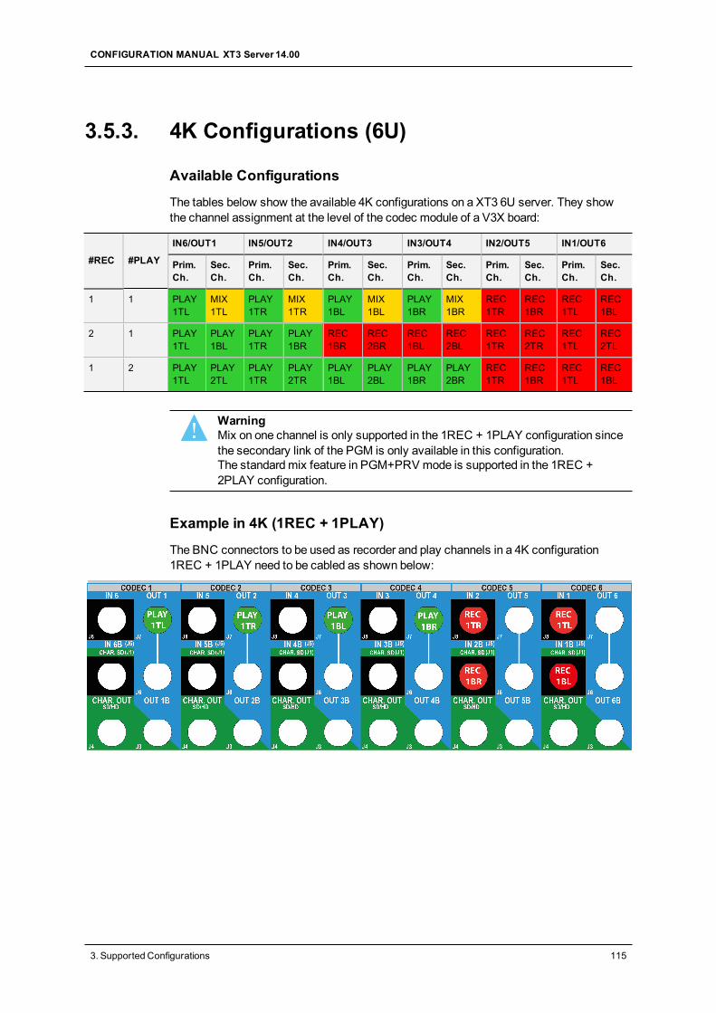
3.5.3. 4K Configurations (6U)
Available Configurations
The tables below show the available 4K configurations on a XT3 6U server. They showthe channel assignment at the level of the codec module of a V3X board:
#REC #PLAY
IN6/OUT1 IN5/OUT2 IN4/OUT3 IN3/OUT4 IN2/OUT5 IN1/OUT6
Prim.Ch.
Sec.Ch.
Prim.Ch.
Sec.Ch.
Prim.Ch.
Sec.Ch.
Prim.Ch.
Sec.Ch.
Prim.Ch.
Sec.Ch.
Prim.Ch.
Sec.Ch.
1 1 PLAY1TL
MIX1TL
PLAY1TR
MIX1TR
PLAY1BL
MIX1BL
PLAY1BR
MIX1BR
REC1TR
REC1BR
REC1TL
REC1BL
2 1 PLAY1TL
PLAY1BL
PLAY1TR
PLAY1BR
REC1BR
REC2BR
REC1BL
REC2BL
REC1TR
REC2TR
REC1TL
REC2TL
1 2 PLAY1TL
PLAY2TL
PLAY1TR
PLAY2TR
PLAY1BL
PLAY2BL
PLAY1BR
PLAY2BR
REC1TR
REC1BR
REC1TL
REC1BL
WarningMix on one channel is only supported in the 1REC + 1PLAY configuration sincethe secondary link of the PGM is only available in this configuration.The standardmix feature in PGM+PRV mode is supported in the 1REC +2PLAY configuration.
Example in 4K (1REC + 1PLAY)
The BNC connectors to be used as recorder and play channels in a 4K configuration1REC + 1PLAY need to be cabled as shown below:
CONFIGURATION MANUAL XT3 Server 14.00
3. Supported Configurations 115
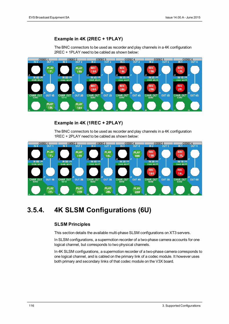
Example in 4K (2REC + 1PLAY)
The BNC connectors to be used as recorder and play channels in a 4K configuration2REC + 1PLAY need to be cabled as shown below:
Example in 4K (1REC + 2PLAY)
The BNC connectors to be used as recorder and play channels in a 4K configuration1REC + 2PLAY need to be cabled as shown below:
3.5.4. 4K SLSM Configurations (6U)
SLSM Principles
This section details the available multi-phase SLSM configurations on XT3 servers.
In SLSM configurations, a supermotion recorder of a two-phase camera accounts for onelogical channel, but corresponds to two physical channels.
In 4K SLSM configurations, a supermotion recorder of a two-phase camera corresponds toone logical channel, and is cabled on the primary link of a codec module. It however usesboth primary and secondary links of that codec module on the V3X board.
116 3. Supported Configurations
EVSBroadcast Equipment SA Issue 14.00.A - June 2015
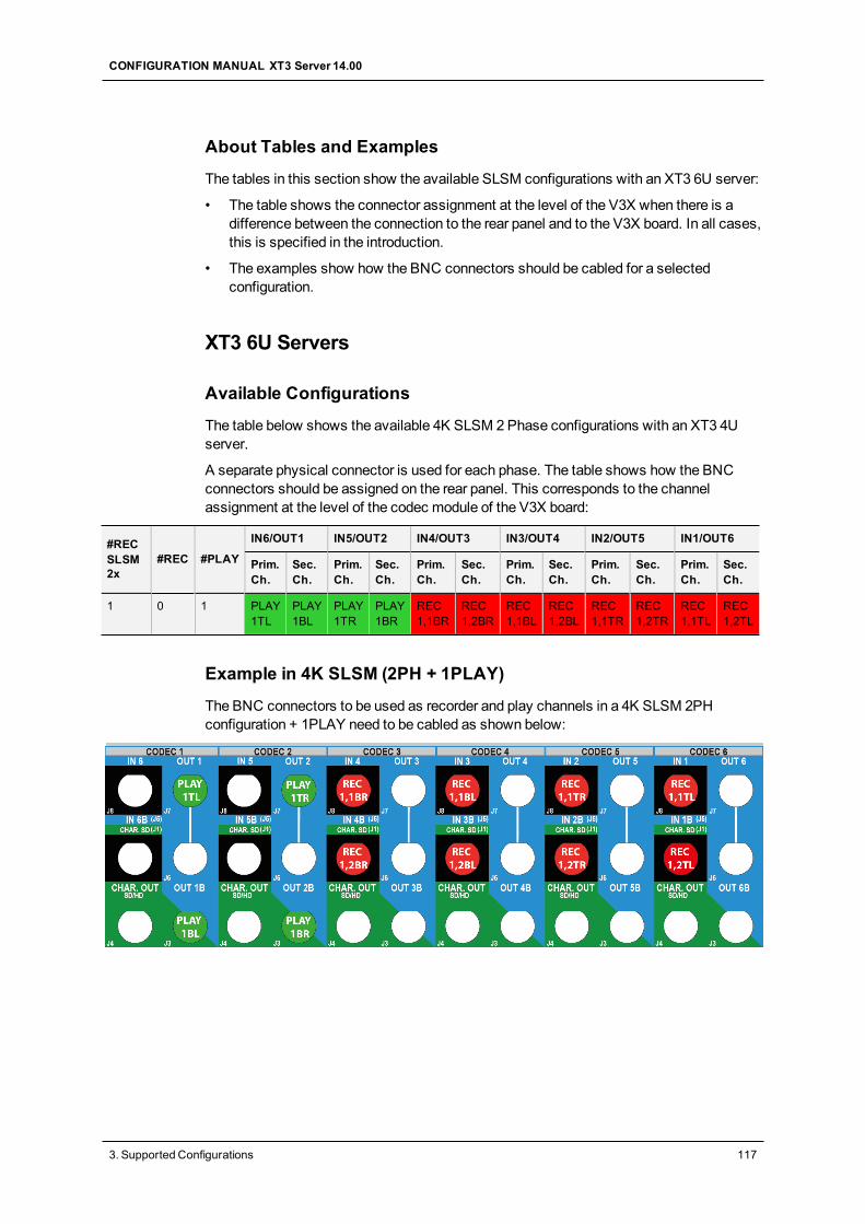
About Tables and Examples
The tables in this section show the available SLSM configurations with an XT3 6U server:
• The table shows the connector assignment at the level of the V3X when there is adifference between the connection to the rear panel and to the V3X board. In all cases,this is specified in the introduction.
• The examples show how the BNC connectors should be cabled for a selectedconfiguration.
XT3 6U Servers
Available Configurations
The table below shows the available 4K SLSM 2Phase configurations with an XT3 4Userver.
A separate physical connector is used for each phase. The table shows how the BNCconnectors should be assigned on the rear panel. This corresponds to the channelassignment at the level of the codec module of the V3X board:
#RECSLSM2x
#REC #PLAY
IN6/OUT1 IN5/OUT2 IN4/OUT3 IN3/OUT4 IN2/OUT5 IN1/OUT6
Prim.Ch.
Sec.Ch.
Prim.Ch.
Sec.Ch.
Prim.Ch.
Sec.Ch.
Prim.Ch.
Sec.Ch.
Prim.Ch.
Sec.Ch.
Prim.Ch.
Sec.Ch.
1 0 1 PLAY1TL
PLAY1BL
PLAY1TR
PLAY1BR
REC1,1BR
REC1,2BR
REC1,1BL
REC1,2BL
REC1,1TR
REC1,2TR
REC1,1TL
REC1,2TL
Example in 4K SLSM (2PH + 1PLAY)
The BNC connectors to be used as recorder and play channels in a 4K SLSM 2PHconfiguration + 1PLAY need to be cabled as shown below:
CONFIGURATION MANUAL XT3 Server 14.00
3. Supported Configurations 117
4. Multicam Configuration
4.1. Overview on User Interfaces
4.1.1. Introduction
Preliminary Remarks
Configuration as Initial Step
Prior to usingMulticam, the operator should set all necessary parameters in theMulticamConfiguration window. If clips are stored with certain parameters and the operator wishesto change the parameter values afterwards, those clips and playlists will not change.
Configuration with Caution
Most parameters are factory preset, and should not bemodified without advice of qualifiedEVS staff. Improper values for some parameters will prevent the proper operation of thesystem.
Parameter Availability
Only the parameters or parameter values valid for the given server type, server chassis,and active license codes are available for defining the various configurations.
General Comparison Between User Interfaces
You can configure the EVS server using one of the three available user interfaces:
• Multicam Configuration window in the server-based application
• Multicam Configuration window in the web-based interface
• Technical andOperational Setupmenus in an EVS Remote Panel (if any)
TheMulticam Configuration windows in the server-based and web-based interface arealmost identical.
In the Remote Panel, however, only themost used technical settings are available in theTechnical Setupmenu, and all operational settings are available in the Operational Setupmenu.
118 4. MulticamConfiguration
EVSBroadcast Equipment SA Issue 14.00.A - June 2015
The following table provides an overview on the features available in each user interface:
Configuration Window
Technical Settings Operational Settings
Server-BasedApplication
Yes(tabs 1-6)
Yes(tab 7)
Web-BasedInterface
Yes(tabs 1-6)
Yes(tab 7)
Remote Panel Yes (partly)(Technical Setup: F0)
Yes(SetupMenu: SHIFT+D)
Overview on Configuration Parameters
The first topic of each section in theMulticam Configuration chapter gives you anoverview on the parameters available in this section, and specifies whether you will findthe parameter:
• in the basic or advanced view in the server-based application and the web-basedinterface
• in the Technical Setup, Operational Setup, or not at all on the Remote Control panel
The following list provides a hyperlink to all overview topics in the various sections:
• Server settings
• Channels settings
• Network settings
• Monitoring settings
• Protocol settings
• GPI settings
• Operations settings
CONFIGURATION MANUAL XT3 Server 14.00
4. MulticamConfiguration 119
Concurrent Modifications in the Remote Panel and theServer-Based Application
When a parameter is modified with the Remote Panel, and that parameter is not in conflictwith the parameter modified in the Configuration page of the server-based application, thefollowingmessage will be displayed on the VGA.
'The configuration has been modified by another user without anyconflict. Your copy has been updated with these modifications.'
When a parameter is modified with the Remote Panel, and the parameter is in conflict withthe parameter modified in the Configuration page of the server-based application, thefollowingmessage will be displayed on the VGA or on the LCD display of the RemotePanel. The configuration will be updated if the user agrees.
'The configuration has been modified by another user.Do you want to load it and lose your modification?'
WarningWhen this message is displayed on the Remote Panel and the user answers'No' to themessage (Clear button), themodifications performed on the RemotePanel will be preserved. The changes applied on the VGA will however beloaded after the user leaves the operational setupmenu, except if the specificfields modified on the VGA have beenmodified and validated on the RemotePanel after themessage display.
4.1.2. Overview of the Multicam ConfigurationWindow
Introduction
In the server-based and web-based interfaces, all server settings related to eachconfiguration file are grouped in a single window: theMulticam Configuration window.
When the server is not running a given configuration, theMulticam Configuration windowallows you to define any of the configurations available in theMulticam Setup window.
When the server is running a given configuration, theMulticam Configuration windowallows you tomodify the settings of the running configuration.
TheMulticam Configuration window is organized in a similar way in both user interfaces:
• It consists of seven tabs.
• Each tab contains one or more pages in the server-based application.
• Each tab displays all settings on a single page in the web-based interface.
• The settings on page/tab are organized in field groups having a dedicated name.
120 4. MulticamConfiguration
EVSBroadcast Equipment SA Issue 14.00.A - June 2015
Accessing the Multicam Configuration Window
In the Server-Based Application
To access theMulticam Configuration window from theMulticam Setup window when theserver is not running, proceed as follows:
1. Press theUP ARROW orDOWN ARROW key to respectively move up and down inthe list of configuration lines until the requested line is highlighted.
2. Press F8.
TheMulticam Configuration window opens.
To access theMulticam Configuration window from the Clips or Playlist window when theserver is running, press SHIFT+F2.
In the Web-Based Interface
To access theMulticam Configuration window from theMulticam Setup window when the
server is not running, click theEdit icon for the configuration line you want toconfigure. TheMulticam Configuration window opens.
TheMulticam Configuration window will directly be displayed on the web-based interfacewhen the server is running a given configuration. You will directly be able to edit thesettings for the running configuration.
Display Mode
The settings in theMulticam Configuration window have been categorized as basic oradvanced settings depending on whether they are commonly used or not.
Two display modes are consequently available:
• Basic mode
• Advancedmode
Selecting the basic mode will hide settings on some pages, or completely hide otherpages.
To change the display mode in the server-based application, press F3.
To change the display mode in the web-based interface, click on the display mode label
or .
CONFIGURATION MANUAL XT3 Server 14.00
4. MulticamConfiguration 121
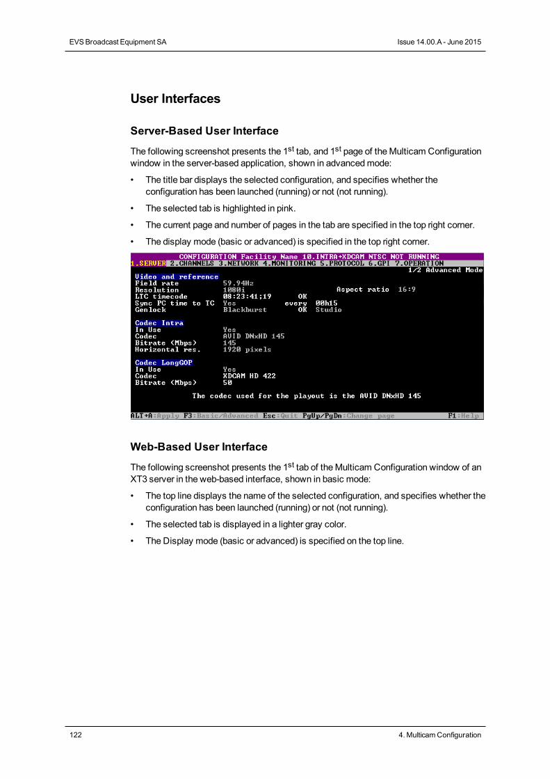
User Interfaces
Server-Based User Interface
The following screenshot presents the 1st tab, and 1st page of theMulticam Configurationwindow in the server-based application, shown in advancedmode:
• The title bar displays the selected configuration, and specifies whether theconfiguration has been launched (running) or not (not running).
• The selected tab is highlighted in pink.
• The current page and number of pages in the tab are specified in the top right corner.
• The display mode (basic or advanced) is specified in the top right corner.
Web-Based User Interface
The following screenshot presents the 1st tab of theMulticam Configuration window of anXT3 server in the web-based interface, shown in basic mode:
• The top line displays the name of the selected configuration, and specifies whether theconfiguration has been launched (running) or not (not running).
• The selected tab is displayed in a lighter gray color.
• The Display mode (basic or advanced) is specified on the top line.
122 4. MulticamConfiguration
EVSBroadcast Equipment SA Issue 14.00.A - June 2015
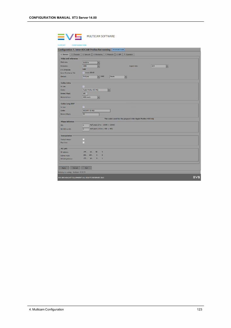
CONFIGURATION MANUAL XT3 Server 14.00
4. MulticamConfiguration 123
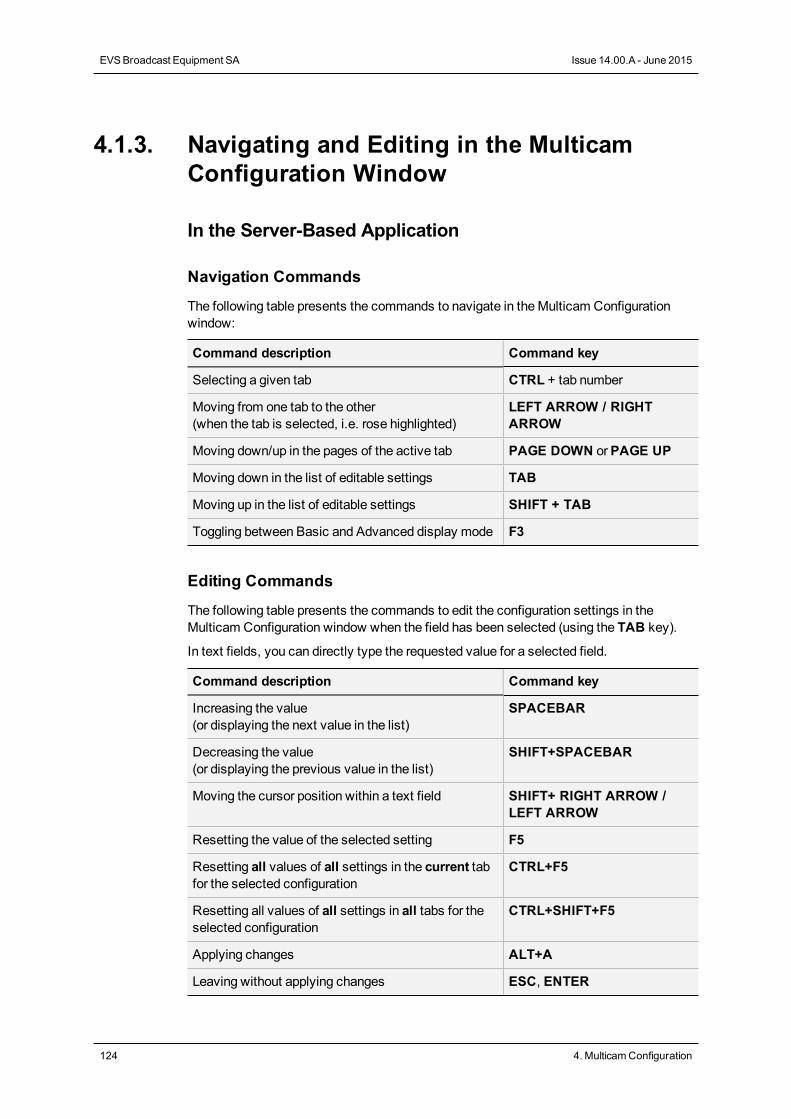
4.1.3. Navigating and Editing in the MulticamConfiguration Window
In the Server-Based Application
Navigation Commands
The following table presents the commands to navigate in theMulticam Configurationwindow:
Command description Command key
Selecting a given tab CTRL + tab number
Moving from one tab to the other(when the tab is selected, i.e. rose highlighted)
LEFT ARROW / RIGHTARROW
Moving down/up in the pages of the active tab PAGE DOWN orPAGE UP
Moving down in the list of editable settings TAB
Moving up in the list of editable settings SHIFT + TAB
Toggling between Basic and Advanced display mode F3
Editing Commands
The following table presents the commands to edit the configuration settings in theMulticam Configuration window when the field has been selected (using the TAB key).
In text fields, you can directly type the requested value for a selected field.
Command description Command key
Increasing the value(or displaying the next value in the list)
SPACEBAR
Decreasing the value(or displaying the previous value in the list)
SHIFT+SPACEBAR
Moving the cursor position within a text field SHIFT+ RIGHT ARROW /LEFT ARROW
Resetting the value of the selected setting F5
Resetting all values of all settings in the current tabfor the selected configuration
CTRL+F5
Resetting all values of all settings in all tabs for theselected configuration
CTRL+SHIFT+F5
Applying changes ALT+A
Leaving without applying changes ESC, ENTER
124 4. MulticamConfiguration
EVSBroadcast Equipment SA Issue 14.00.A - June 2015
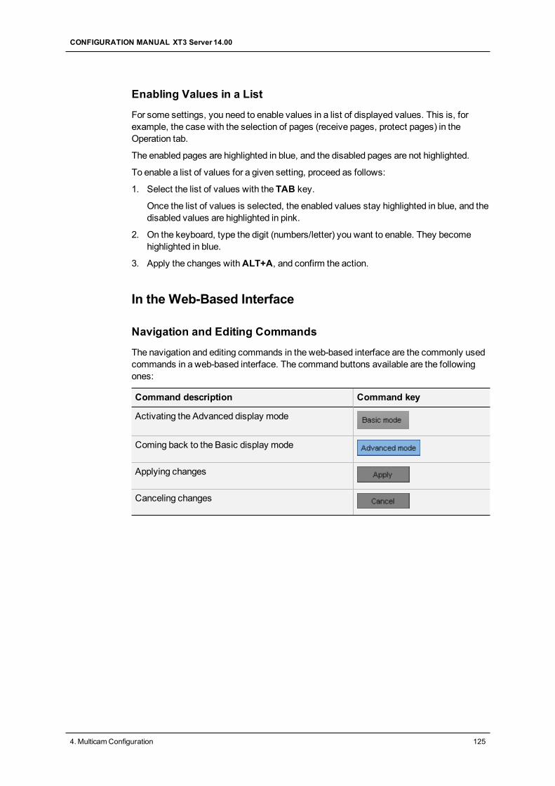
Enabling Values in a List
For some settings, you need to enable values in a list of displayed values. This is, forexample, the case with the selection of pages (receive pages, protect pages) in theOperation tab.
The enabled pages are highlighted in blue, and the disabled pages are not highlighted.
To enable a list of values for a given setting, proceed as follows:
1. Select the list of values with the TAB key.
Once the list of values is selected, the enabled values stay highlighted in blue, and thedisabled values are highlighted in pink.
2. On the keyboard, type the digit (numbers/letter) you want to enable. They becomehighlighted in blue.
3. Apply the changes withALT+A, and confirm the action.
In the Web-Based Interface
Navigation and Editing Commands
The navigation and editing commands in the web-based interface are the commonly usedcommands in a web-based interface. The command buttons available are the followingones:
Command description Command key
Activating the Advanced display mode
Coming back to the Basic display mode
Applying changes
Canceling changes
CONFIGURATION MANUAL XT3 Server 14.00
4. MulticamConfiguration 125
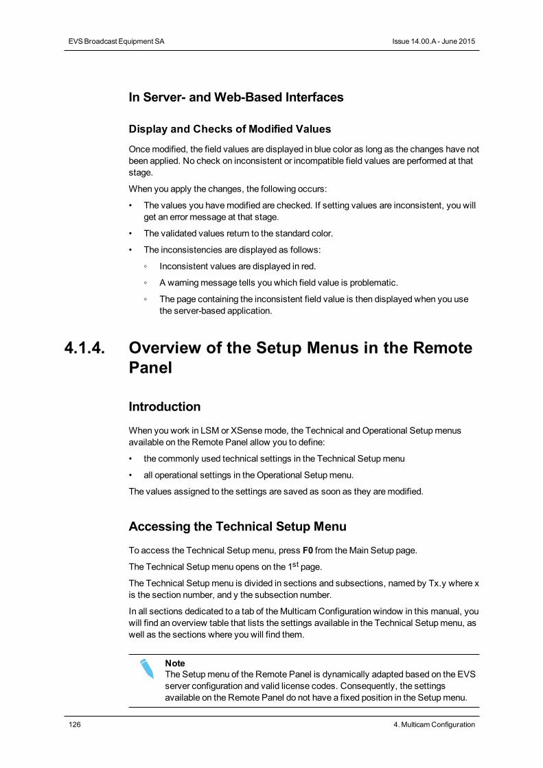
In Server- and Web-Based Interfaces
Display and Checks of Modified Values
Oncemodified, the field values are displayed in blue color as long as the changes have notbeen applied. No check on inconsistent or incompatible field values are performed at thatstage.
When you apply the changes, the following occurs:
• The values you havemodified are checked. If setting values are inconsistent, you willget an error message at that stage.
• The validated values return to the standard color.
• The inconsistencies are displayed as follows:
◦ Inconsistent values are displayed in red.
◦ A warningmessage tells you which field value is problematic.
◦ The page containing the inconsistent field value is then displayed when you usethe server-based application.
4.1.4. Overview of the Setup Menus in the RemotePanel
Introduction
When you work in LSM or XSense mode, the Technical andOperational Setupmenusavailable on the Remote Panel allow you to define:
• the commonly used technical settings in the Technical Setupmenu
• all operational settings in the Operational Setupmenu.
The values assigned to the settings are saved as soon as they aremodified.
Accessing the Technical Setup Menu
To access the Technical Setupmenu, press F0 from theMain Setup page.
The Technical Setupmenu opens on the 1st page.
The Technical Setupmenu is divided in sections and subsections, named by Tx.y where xis the section number, and y the subsection number.
In all sections dedicated to a tab of theMulticam Configuration window in this manual, youwill find an overview table that lists the settings available in the Technical Setupmenu, aswell as the sections where you will find them.
NoteThe Setupmenu of the Remote Panel is dynamically adapted based on the EVSserver configuration and valid license codes. Consequently, the settingsavailable on the Remote Panel do not have a fixed position in the Setupmenu.
126 4. MulticamConfiguration
EVSBroadcast Equipment SA Issue 14.00.A - June 2015
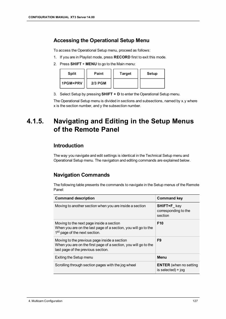
Accessing the Operational Setup Menu
To access the Operational Setupmenu, proceed as follows:
1. If you are in Playlist mode, press RECORD first to exit this mode.
2. Press SHIFT +MENU to go to theMainmenu:
3. Select Setup by pressingSHIFT + D to enter the Operational Setupmenu.
TheOperational Setupmenu is divided in sections and subsections, named by x.y wherex is the section number, and y the subsection number.
4.1.5. Navigating and Editing in the Setup Menusof the Remote Panel
Introduction
The way you navigate and edit settings is identical in the Technical Setupmenu andOperational Setupmenu. The navigation and editing commands are explained below.
Navigation Commands
The following table presents the commands to navigate in the Setupmenus of the RemotePanel:
Command description Command key
Moving to another section when you are inside a section SHIFT+F_ keycorresponding to thesection
Moving to the next page inside a sectionWhen you are on the last page of a section, you will go to the1st page of the next section.
F10
Moving to the previous page inside a sectionWhen you are on the first page of a section, you will go to thelast page of the previous section.
F9
Exiting the Setupmenu Menu
Scrolling through section pages with the jog wheel ENTER (when no settingis selected) + jog
CONFIGURATION MANUAL XT3 Server 14.00
4. MulticamConfiguration 127
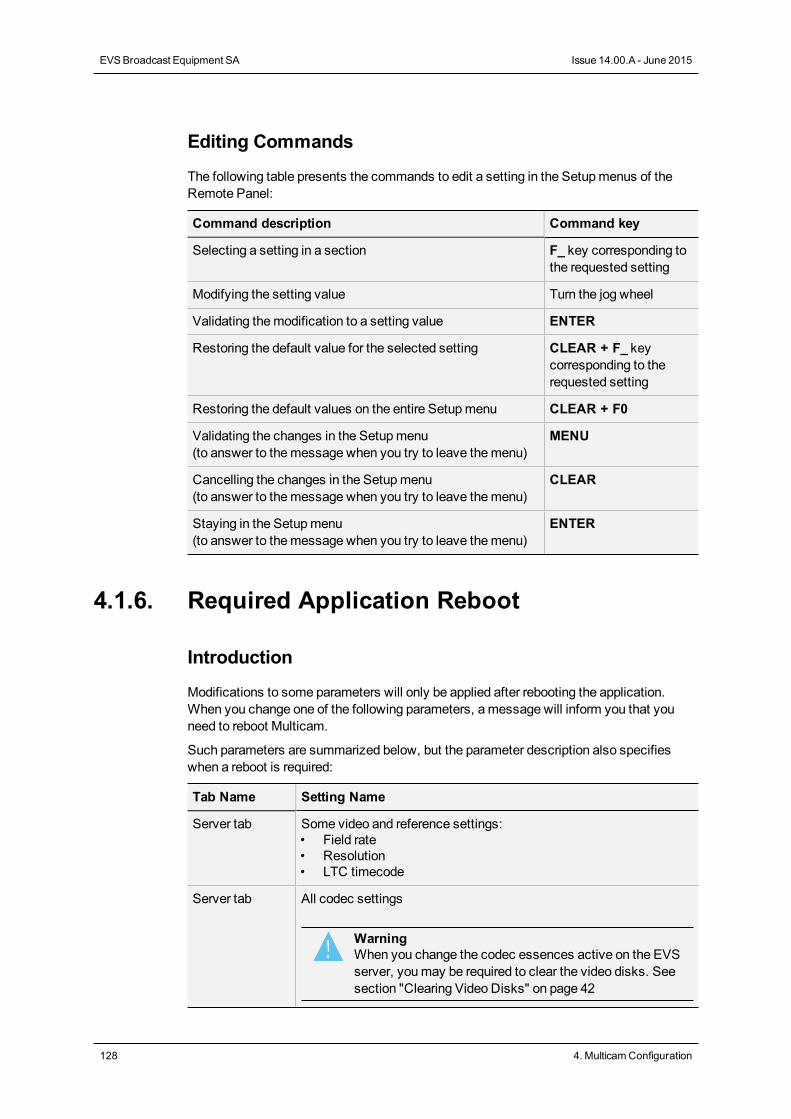
Editing Commands
The following table presents the commands to edit a setting in the Setupmenus of theRemote Panel:
Command description Command key
Selecting a setting in a section F_ key corresponding tothe requested setting
Modifying the setting value Turn the jog wheel
Validating themodification to a setting value ENTER
Restoring the default value for the selected setting CLEAR + F_ keycorresponding to therequested setting
Restoring the default values on the entire Setupmenu CLEAR + F0
Validating the changes in the Setupmenu(to answer to themessage when you try to leave themenu)
MENU
Cancelling the changes in the Setupmenu(to answer to themessage when you try to leave themenu)
CLEAR
Staying in the Setupmenu(to answer to themessage when you try to leave themenu)
ENTER
4.1.6. Required Application Reboot
Introduction
Modifications to some parameters will only be applied after rebooting the application.When you change one of the following parameters, amessage will inform you that youneed to reboot Multicam.
Such parameters are summarized below, but the parameter description also specifieswhen a reboot is required:
Tab Name Setting Name
Server tab Some video and reference settings:• Field rate• Resolution• LTC timecode
Server tab All codec settings
WarningWhen you change the codec essences active on the EVSserver, youmay be required to clear the video disks. Seesection "Clearing Video Disks" on page 42
128 4. MulticamConfiguration
EVSBroadcast Equipment SA Issue 14.00.A - June 2015
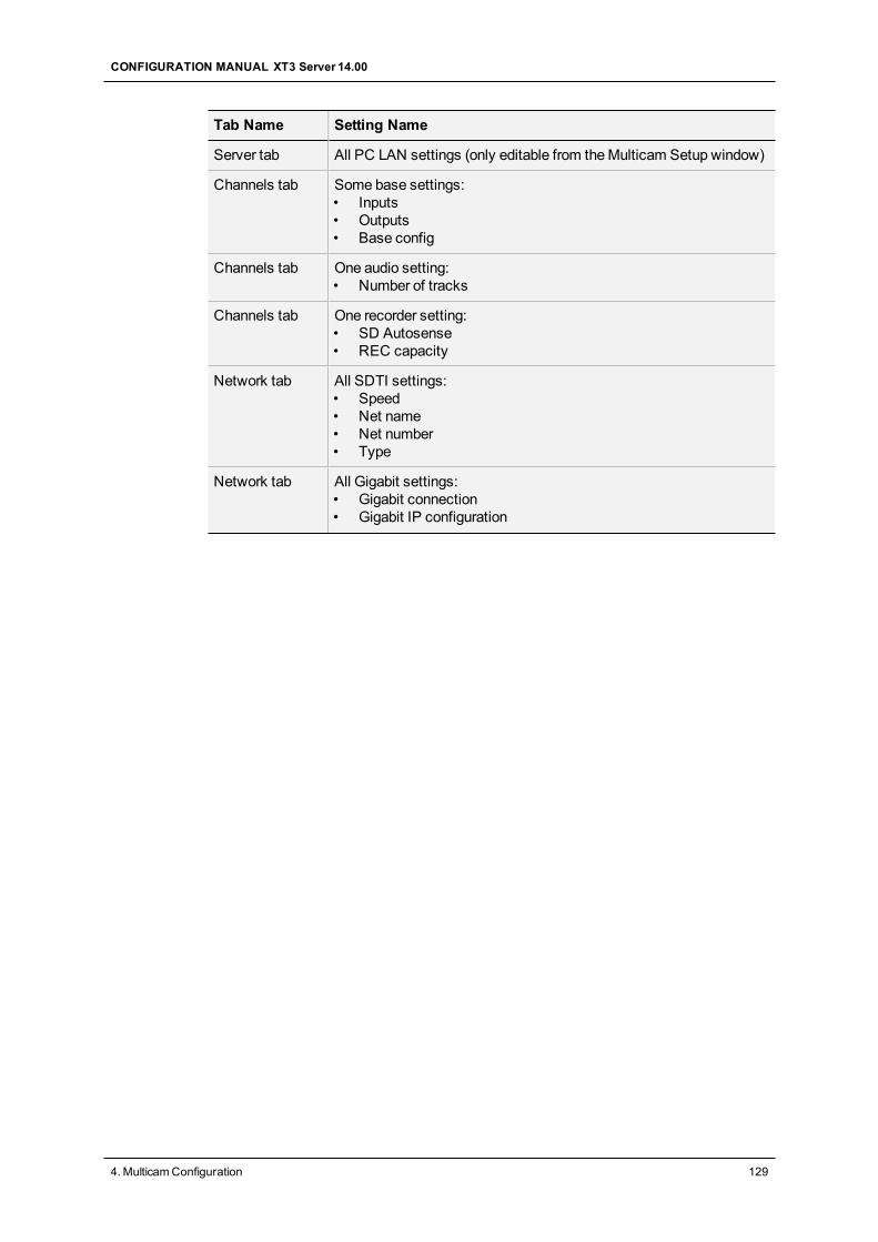
Tab Name Setting Name
Server tab All PC LAN settings (only editable from theMulticam Setup window)
Channels tab Some base settings:• Inputs• Outputs• Base config
Channels tab One audio setting:• Number of tracks
Channels tab One recorder setting:• SD Autosense• REC capacity
Network tab All SDTI settings:• Speed• Net name• Net number• Type
Network tab All Gigabit settings:• Gigabit connection• Gigabit IP configuration
CONFIGURATION MANUAL XT3 Server 14.00
4. MulticamConfiguration 129
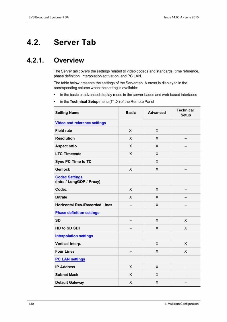
4.2. Server Tab
4.2.1. OverviewThe Server tab covers the settings related to video codecs and standards, time reference,phase definition, interpolation activation, and PC LAN.
The table below presents the settings of the Server tab. A cross is displayed in thecorresponding columnwhen the setting is available:
• in the basic or advanced display mode in the server-based and web-based interfaces
• in the Technical Setupmenu (T1.X) of the Remote Panel
Setting Name Basic Advanced TechnicalSetup
Video and reference settings
Field rate X X –
Resolution X X –
Aspect ratio X X –
LTC Timecode X X –
Sync PC Time to TC – X –
Genlock X X –
Codec Settings(Intra / LongGOP / Proxy)
Codec X X –
Bitrate X X –
Horizontal Res./Recorded Lines – X –
Phase definition settings
SD – X X
HD to SD SDI – X X
Interpolation settings
Vertical interp. – X X
Four Lines – X X
PC LAN settings
IP Address X X –
Subnet Mask X X –
Default Gateway X X –
130 4. MulticamConfiguration
EVSBroadcast Equipment SA Issue 14.00.A - June 2015
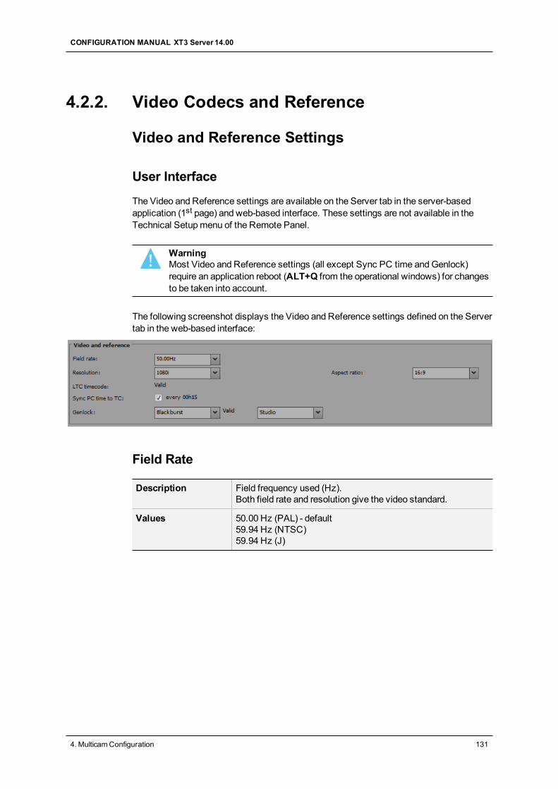
4.2.2. Video Codecs and Reference
Video and Reference Settings
User Interface
The Video and Reference settings are available on the Server tab in the server-basedapplication (1st page) and web-based interface. These settings are not available in theTechnical Setupmenu of the Remote Panel.
WarningMost Video and Reference settings (all except Sync PC time andGenlock)require an application reboot (ALT+Q from the operational windows) for changesto be taken into account.
The following screenshot displays the Video and Reference settings defined on the Servertab in the web-based interface:
Field Rate
Description Field frequency used (Hz).Both field rate and resolution give the video standard.
Values 50.00 Hz (PAL) - default59.94 Hz (NTSC)59.94 Hz (J)
CONFIGURATION MANUAL XT3 Server 14.00
4. MulticamConfiguration 131
Resolution
Description Vertical resolution used (number of white-to-black and black-to-white transitions that can be seen from the top to the bottom ofthe picture) (pixel + type).Both field rate and resolution correspond to the video standard.With an XT3 server, SD and HD video standards can beavailable if the relevant license codes are activated.
Values In SD:• 525i• 625iIn HD:• 720p• 1080i• 1080p (only available with code 21 or 22)In 3G:• UHDTV-4K
Aspect ratio
Description Specifies the aspect ratio of the content provided on the inputvideo signal.
Values The following values are available:In SD:• 16:9• 4:3• 4:3 Letterbox:Black stripes are placed above and below
the active video to compensate for the full width.• 16.9 Pillarbox:Black stripes are placed left and right of the
active video to fill in themissing pixels.In HD:• 16:9• 16.9 Pillarbox
Default value 16:9
LTC Timecode
Description Longitudinal timecode (timecode information stored on aseparate track from the video) delivered to the EVS server, andtimecode status.
Values The timecode is given as hh:mm:ss:fr (only on the server-based application)The timecode status can be 'OK or Valid', 'BAD', 'LOST' or'DRIFT' (defined by the EVS server).
132 4. MulticamConfiguration
EVSBroadcast Equipment SA Issue 14.00.A - June 2015
Sync PC Time to TC
Description Specifies whether the PC time is synchronized with thetimecode, and how often the synchronization takes place.
Values Synchronization:Yes/NoFrequency: by default 'every 00h15' (not editable)
Genlock
Description Specifies the type of genlock signal, the status and the framesynchronizer mode.
Values Type: 'Blackburst' or 'Tri-Sync' (always 'Blackburst' in SD)Status: 'OK or Valid' or 'BAD' (defined by the EVS server)Mode: 'Studio' (no correction of a shifted video signal) or'Resync' (resynchronization of a shifted video signal)
About Multi-Essence
Introduction
The XT3 server can encode, at a time, a record train in two different codec types, whichare called essences. The following essences are available: Intra and/or LongGOP(XDCAM) orProxy (Lo-Res). This process is seamless to the user, who will go onworking as before with the EVS server.
This section provides an overview of themulti-essence feature, andmainly specifies therules and restrictions you should take into account when you configure an XT3 server inmulti-essence.
Essence Combinations
The essences can be combined as follows:
• Intra + LongGOP
• Intra + Proxy
• Intra only
• LongGOP only
CONFIGURATION MANUAL XT3 Server 14.00
4. MulticamConfiguration 133
General Rules
• You will only see one record train per record channel and one clip per LSMID even ifthe record trains and clips exist in several essences on the EVS server.
• A single clip is identical in all available essences.
• The Proxy essence can not be used as a single essence on an EVS server.
Recording and Editing Rules
• When the server is configured inmulti-essencemode, the clips are created in eachactive essence.
• In general, all editing actions on clips are applied seamlessly on all active essences ofthe clip.
Playout Rules
• Only one essence can be played out at a time. The codec used for playout is specifiedin the Server tab, after the codec sections.
• When the Intra essence is in use on the server, this essence is played out. Otherwise,the LongGOP essence is played out.
• If the on-air essence is not available, a black clip is displayed.
• The Proxy essence is never played out.
Limitations
With LongGOP Codec
With SLSM configurations in multi-essence Intra + LongGOP, the following limitationprevails:
• the Intra codec records all phases
• the LongGOP codec records only the regular speed content (not SLSM) from phase 1.
With Proxy Codec
Dolby E is not supported in Proxy essence. If audio channels are configured in Dolby E inamulti-essence configuration with Proxy, the Proxy output will have no associated audio.
NoteThe Lo-Res audio is Mpeg-1 Layer II at 48 kHz sampling frequency.
134 4. MulticamConfiguration
EVSBroadcast Equipment SA Issue 14.00.A - June 2015
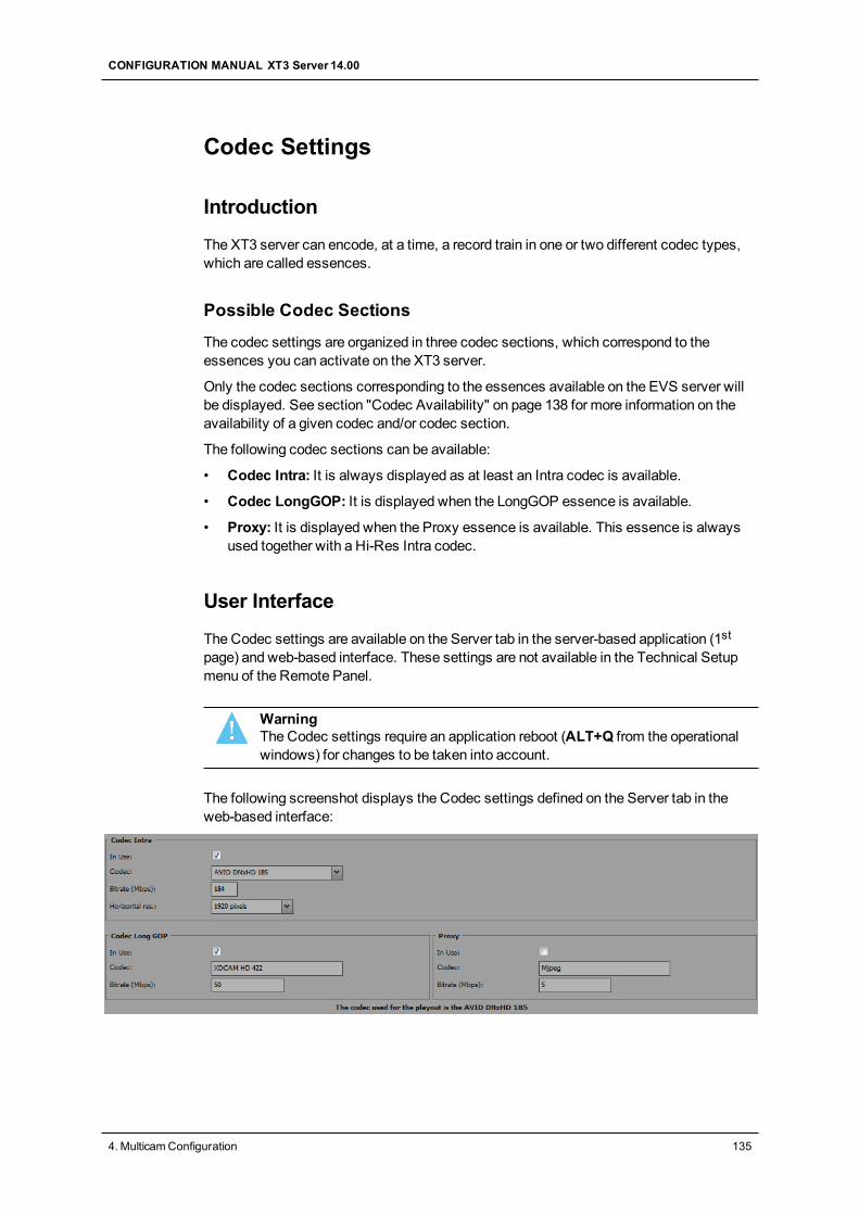
Codec Settings
Introduction
The XT3 server can encode, at a time, a record train in one or two different codec types,which are called essences.
Possible Codec Sections
The codec settings are organized in three codec sections, which correspond to theessences you can activate on the XT3 server.
Only the codec sections corresponding to the essences available on the EVS server willbe displayed. See section "Codec Availability" on page 138 for more information on theavailability of a given codec and/or codec section.
The following codec sections can be available:
• Codec Intra: It is always displayed as at least an Intra codec is available.
• Codec LongGOP: It is displayed when the LongGOP essence is available.
• Proxy: It is displayed when the Proxy essence is available. This essence is alwaysused together with a Hi-Res Intra codec.
User Interface
The Codec settings are available on the Server tab in the server-based application (1stpage) and web-based interface. These settings are not available in the Technical Setupmenu of the Remote Panel.
WarningThe Codec settings require an application reboot (ALT+Q from the operationalwindows) for changes to be taken into account.
The following screenshot displays the Codec settings defined on the Server tab in theweb-based interface:
CONFIGURATION MANUAL XT3 Server 14.00
4. MulticamConfiguration 135
In Use
Description Specifies, in each essence section, whether the given essenceis encoded or not on the EVS server.
Values • Yes• No
Default value Yes in Intra Codec sectionNo in LongGOP andProxy sections
Codec (Codec Intra)
Description Algorithm used to compress and decompress the video signal.With Intra codecs, the compression techniques are performedexclusiverly relative to information contained within the currentframe.
Values In SD:• Mjpeg (SD)• IMX• DVCPro 50In HD:• Mjpeg EVS (HD)• Mjpeg Standard (HD)• Mpeg 2 Intra (HD)• Avid DNxHD 120, 185 or 185x (only in 50 Hz)• Avid DNxHD 145, 220 or 220x (only in 59.94 Hz)• Apple ProRes 422, 422 LT, 422 HQ• DVCPro HD• AVC-Intra 100See section "Codec Availability" on page 138 for detailedinformation on codec availability.
Default values • IMX in SD• Avid DNxHD 120 in HD 50Hz• Avid DNxHD 145 in HD 59.94 Hz
NoteWhen the EVS server is configured to work in AVC-Intra codec, the XAVCcodec is also available in playout.
136 4. MulticamConfiguration
EVSBroadcast Equipment SA Issue 14.00.A - June 2015
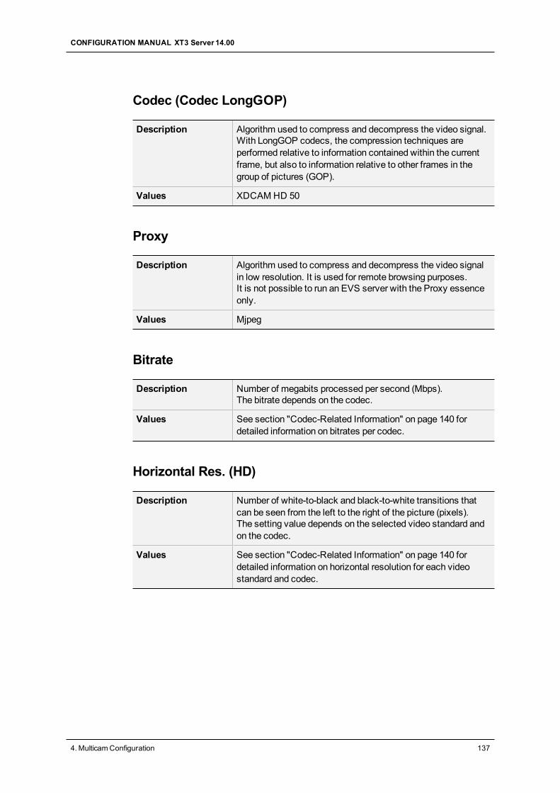
Codec (Codec LongGOP)
Description Algorithm used to compress and decompress the video signal.With LongGOP codecs, the compression techniques areperformed relative to information contained within the currentframe, but also to information relative to other frames in thegroup of pictures (GOP).
Values XDCAMHD 50
Proxy
Description Algorithm used to compress and decompress the video signalin low resolution. It is used for remote browsing purposes.It is not possible to run an EVS server with the Proxy essenceonly.
Values Mjpeg
Bitrate
Description Number of megabits processed per second (Mbps).The bitrate depends on the codec.
Values See section "Codec-Related Information" on page 140 fordetailed information on bitrates per codec.
Horizontal Res. (HD)
Description Number of white-to-black and black-to-white transitions thatcan be seen from the left to the right of the picture (pixels).The setting value depends on the selected video standard andon the codec.
Values See section "Codec-Related Information" on page 140 fordetailed information on horizontal resolution for each videostandard and codec.
CONFIGURATION MANUAL XT3 Server 14.00
4. MulticamConfiguration 137
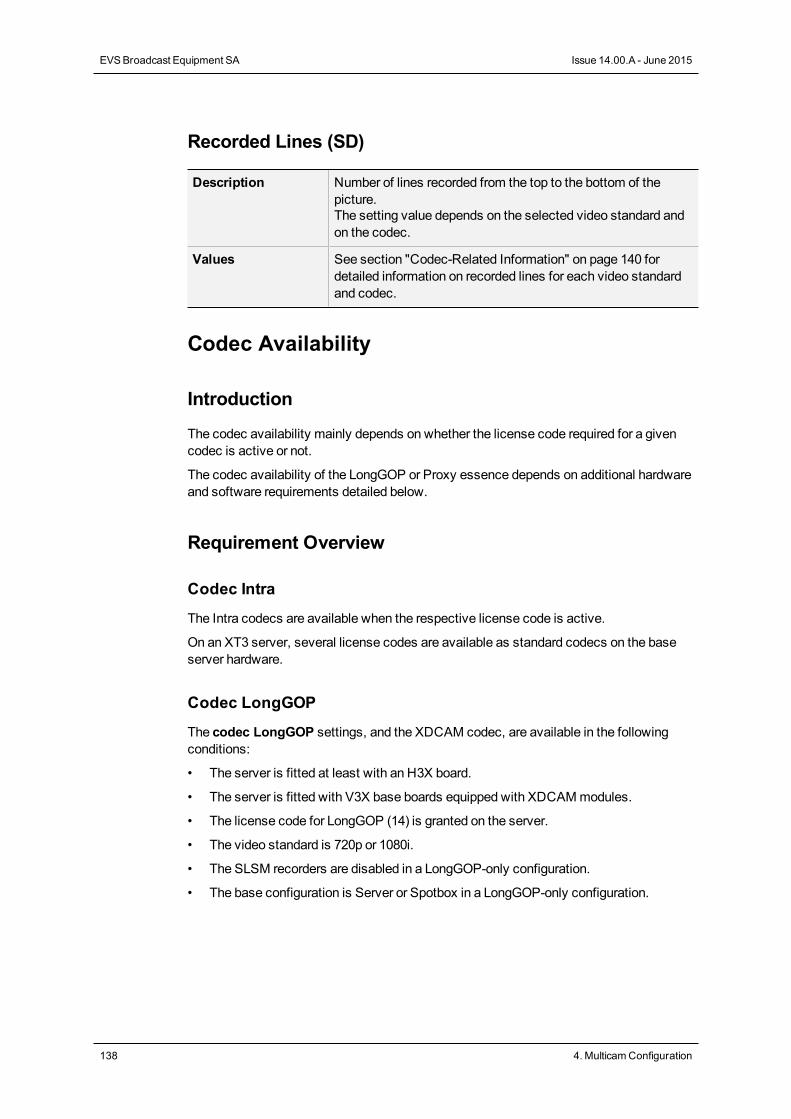
Recorded Lines (SD)
Description Number of lines recorded from the top to the bottom of thepicture.The setting value depends on the selected video standard andon the codec.
Values See section "Codec-Related Information" on page 140 fordetailed information on recorded lines for each video standardand codec.
Codec Availability
Introduction
The codec availability mainly depends on whether the license code required for a givencodec is active or not.
The codec availability of the LongGOP or Proxy essence depends on additional hardwareand software requirements detailed below.
Requirement Overview
Codec Intra
The Intra codecs are available when the respective license code is active.
On an XT3 server, several license codes are available as standard codecs on the baseserver hardware.
Codec LongGOP
The codec LongGOP settings, and the XDCAM codec, are available in the followingconditions:
• The server is fitted at least with an H3X board.
• The server is fitted with V3X base boards equipped with XDCAMmodules.
• The license code for LongGOP (14) is granted on the server.
• The video standard is 720p or 1080i.
• The SLSM recorders are disabled in a LongGOP-only configuration.
• The base configuration is Server or Spotbox in a LongGOP-only configuration.
138 4. MulticamConfiguration
EVSBroadcast Equipment SA Issue 14.00.A - June 2015
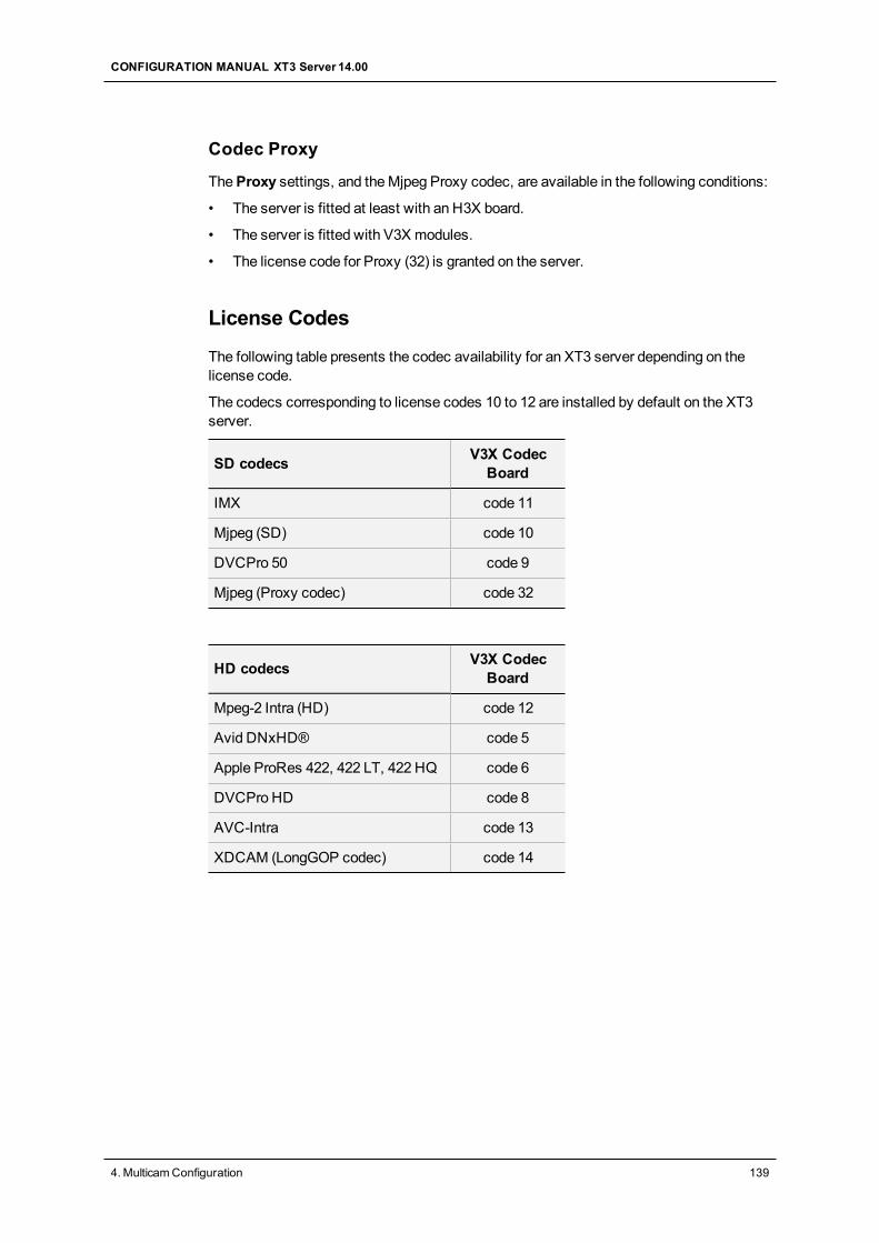
Codec Proxy
TheProxy settings, and theMjpeg Proxy codec, are available in the following conditions:
• The server is fitted at least with an H3X board.
• The server is fitted with V3X modules.
• The license code for Proxy (32) is granted on the server.
License Codes
The following table presents the codec availability for an XT3 server depending on thelicense code.
The codecs corresponding to license codes 10 to 12 are installed by default on the XT3server.
SD codecs V3X CodecBoard
IMX code 11
Mjpeg (SD) code 10
DVCPro 50 code 9
Mjpeg (Proxy codec) code 32
HD codecs V3X CodecBoard
Mpeg-2 Intra (HD) code 12
Avid DNxHD® code 5
Apple ProRes 422, 422 LT, 422 HQ code 6
DVCPro HD code 8
AVC-Intra code 13
XDCAM (LongGOP codec) code 14
CONFIGURATION MANUAL XT3 Server 14.00
4. MulticamConfiguration 139
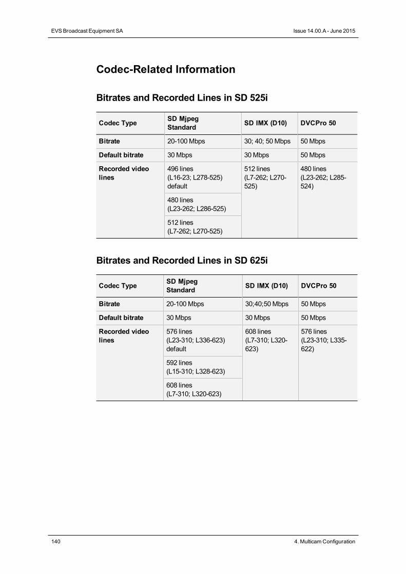
Codec-Related Information
Bitrates and Recorded Lines in SD 525i
Codec Type SD MjpegStandard SD IMX (D10) DVCPro 50
Bitrate 20-100Mbps 30; 40; 50Mbps 50Mbps
Default bitrate 30Mbps 30Mbps 50Mbps
Recorded videolines
496 lines(L16-23; L278-525)default
512 lines(L7-262; L270-525)
480 lines(L23-262; L285-524)
480 lines(L23-262; L286-525)
512 lines(L7-262; L270-525)
Bitrates and Recorded Lines in SD 625i
Codec Type SD MjpegStandard SD IMX (D10) DVCPro 50
Bitrate 20-100Mbps 30;40;50Mbps 50Mbps
Default bitrate 30Mbps 30Mbps 50Mbps
Recorded videolines
576 lines(L23-310; L336-623)default
608 lines(L7-310; L320-623)
576 lines(L23-310; L335-622)
592 lines(L15-310; L328-623)
608 lines(L7-310; L320-623)
140 4. MulticamConfiguration
EVSBroadcast Equipment SA Issue 14.00.A - June 2015
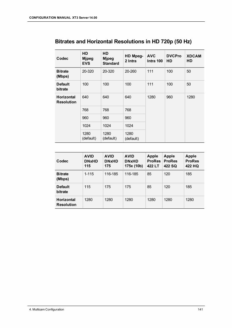
Bitrates and Horizontal Resolutions in HD 720p (50 Hz)
CodecHDMjpegEVS
HDMjpegStandard
HD Mpeg-2 Intra
AVCIntra 100
DVCProHD
XDCAMHD
Bitrate(Mbps)
20-320 20-320 20-260 111 100 50
Defaultbitrate
100 100 100 111 100 50
HorizontalResolution
640 640 640 1280 960 1280
768 768 768
960 960 960
1024 1024 1024
1280(default)
1280(default)
1280(default)
CodecAVIDDNxHD115
AVIDDNxHD175
AVIDDNxHD175x (10b)
AppleProRes422 LT
AppleProRes422 SQ
AppleProRes422 HQ
Bitrate(Mbps)
1-115 116-185 116-185 85 120 185
Defaultbitrate
115 175 175 85 120 185
HorizontalResolution
1280 1280 1280 1280 1280 1280
CONFIGURATION MANUAL XT3 Server 14.00
4. MulticamConfiguration 141
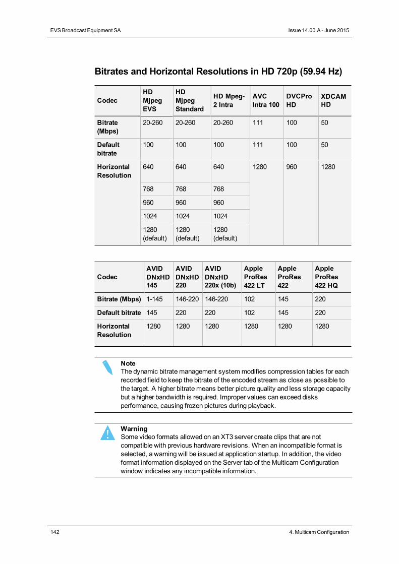
Bitrates and Horizontal Resolutions in HD 720p (59.94 Hz)
CodecHDMjpegEVS
HDMjpegStandard
HD Mpeg-2 Intra
AVCIntra 100
DVCProHD
XDCAMHD
Bitrate(Mbps)
20-260 20-260 20-260 111 100 50
Defaultbitrate
100 100 100 111 100 50
HorizontalResolution
640 640 640 1280 960 1280
768 768 768
960 960 960
1024 1024 1024
1280(default)
1280(default)
1280(default)
CodecAVIDDNxHD145
AVIDDNxHD220
AVIDDNxHD220x (10b)
AppleProRes422 LT
AppleProRes422
AppleProRes422 HQ
Bitrate (Mbps) 1-145 146-220 146-220 102 145 220
Default bitrate 145 220 220 102 145 220
HorizontalResolution
1280 1280 1280 1280 1280 1280
NoteThe dynamic bitrate management systemmodifies compression tables for eachrecorded field to keep the bitrate of the encoded stream as close as possible tothe target. A higher bitrate means better picture quality and less storage capacitybut a higher bandwidth is required. Improper values can exceed disksperformance, causing frozen pictures during playback.
WarningSome video formats allowed on an XT3 server create clips that are notcompatible with previous hardware revisions. When an incompatible format isselected, a warning will be issued at application startup. In addition, the videoformat information displayed on the Server tab of theMulticam Configurationwindow indicates any incompatible information.
142 4. MulticamConfiguration
EVSBroadcast Equipment SA Issue 14.00.A - June 2015
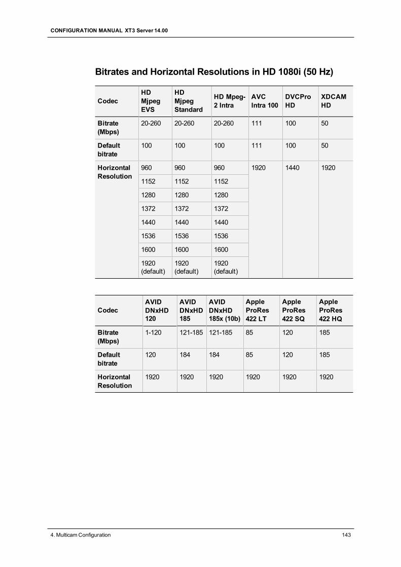
Bitrates and Horizontal Resolutions in HD 1080i (50 Hz)
CodecHDMjpegEVS
HDMjpegStandard
HD Mpeg-2 Intra
AVCIntra 100
DVCProHD
XDCAMHD
Bitrate(Mbps)
20-260 20-260 20-260 111 100 50
Defaultbitrate
100 100 100 111 100 50
HorizontalResolution
960 960 960 1920 1440 1920
1152 1152 1152
1280 1280 1280
1372 1372 1372
1440 1440 1440
1536 1536 1536
1600 1600 1600
1920(default)
1920(default)
1920(default)
CodecAVIDDNxHD120
AVIDDNxHD185
AVIDDNxHD185x (10b)
AppleProRes422 LT
AppleProRes422 SQ
AppleProRes422 HQ
Bitrate(Mbps)
1-120 121-185 121-185 85 120 185
Defaultbitrate
120 184 184 85 120 185
HorizontalResolution
1920 1920 1920 1920 1920 1920
CONFIGURATION MANUAL XT3 Server 14.00
4. MulticamConfiguration 143
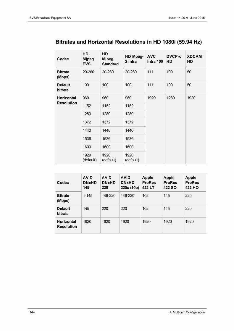
Bitrates and Horizontal Resolutions in HD 1080i (59.94 Hz)
CodecHDMjpegEVS
HDMjpegStandard
HD Mpeg-2 Intra
AVCIntra 100
DVCProHD
XDCAMHD
Bitrate(Mbps)
20-260 20-260 20-260 111 100 50
Defaultbitrate
100 100 100 111 100 50
HorizontalResolution
960 960 960 1920 1280 1920
1152 1152 1152
1280 1280 1280
1372 1372 1372
1440 1440 1440
1536 1536 1536
1600 1600 1600
1920(default)
1920(default)
1920(default)
CodecAVIDDNxHD145
AVIDDNxHD220
AVIDDNxHD220x (10b)
AppleProRes422 LT
AppleProRes422 SQ
AppleProRes422 HQ
Bitrate(Mbps)
1-145 146-220 146-220 102 145 220
Defaultbitrate
145 220 220 102 145 220
HorizontalResolution
1920 1920 1920 1920 1920 1920
144 4. MulticamConfiguration
EVSBroadcast Equipment SA Issue 14.00.A - June 2015
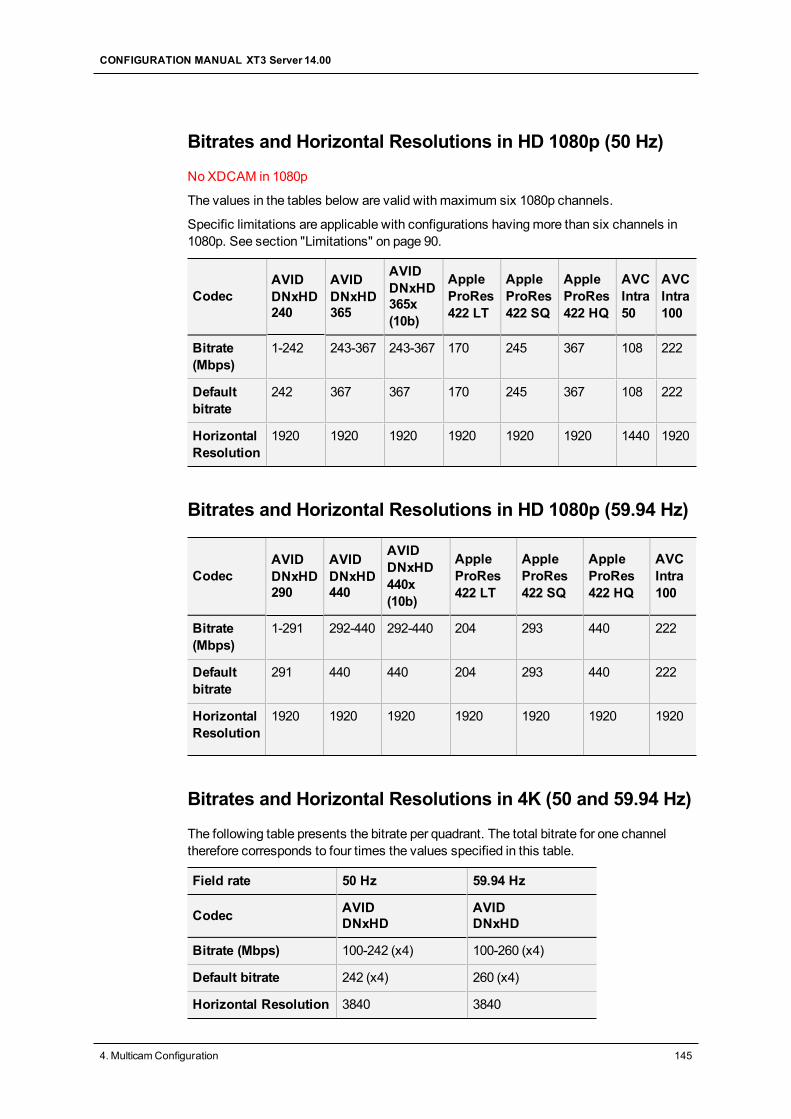
Bitrates and Horizontal Resolutions in HD 1080p (50 Hz)
NoXDCAM in 1080p
The values in the tables below are valid with maximum six 1080p channels.
Specific limitations are applicable with configurations havingmore than six channels in1080p. See section "Limitations" on page 90.
CodecAVIDDNxHD240
AVIDDNxHD365
AVIDDNxHD365x(10b)
AppleProRes422 LT
AppleProRes422 SQ
AppleProRes422 HQ
AVCIntra50
AVCIntra100
Bitrate(Mbps)
1-242 243-367 243-367 170 245 367 108 222
Defaultbitrate
242 367 367 170 245 367 108 222
HorizontalResolution
1920 1920 1920 1920 1920 1920 1440 1920
Bitrates and Horizontal Resolutions in HD 1080p (59.94 Hz)
CodecAVIDDNxHD290
AVIDDNxHD440
AVIDDNxHD440x(10b)
AppleProRes422 LT
AppleProRes422 SQ
AppleProRes422 HQ
AVCIntra100
Bitrate(Mbps)
1-291 292-440 292-440 204 293 440 222
Defaultbitrate
291 440 440 204 293 440 222
HorizontalResolution
1920 1920 1920 1920 1920 1920 1920
Bitrates and Horizontal Resolutions in 4K (50 and 59.94 Hz)
The following table presents the bitrate per quadrant. The total bitrate for one channeltherefore corresponds to four times the values specified in this table.
Field rate 50 Hz 59.94 Hz
Codec AVIDDNxHD
AVIDDNxHD
Bitrate (Mbps) 100-242 (x4) 100-260 (x4)
Default bitrate 242 (x4) 260 (x4)
Horizontal Resolution 3840 3840
CONFIGURATION MANUAL XT3 Server 14.00
4. MulticamConfiguration 145
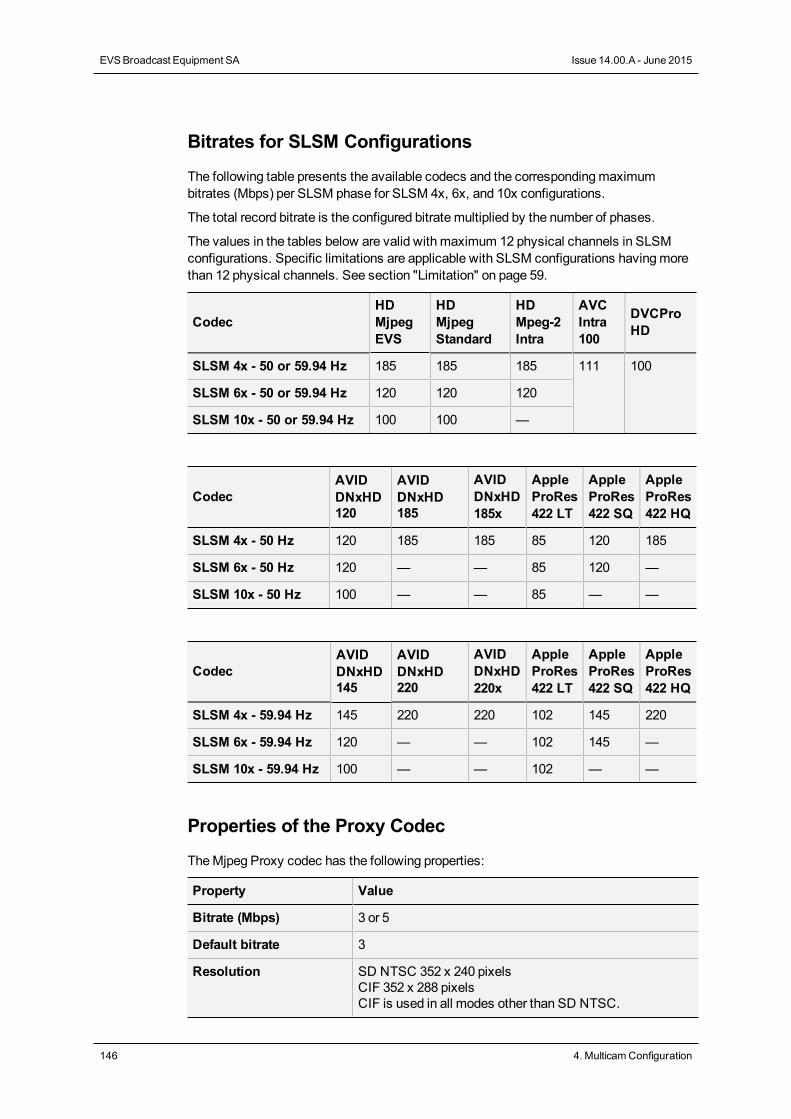
Bitrates for SLSM Configurations
The following table presents the available codecs and the correspondingmaximumbitrates (Mbps) per SLSM phase for SLSM 4x, 6x, and 10x configurations.
The total record bitrate is the configured bitrate multiplied by the number of phases.
The values in the tables below are valid with maximum 12 physical channels in SLSMconfigurations. Specific limitations are applicable with SLSM configurations havingmorethan 12 physical channels. See section "Limitation" on page 59.
CodecHDMjpegEVS
HDMjpegStandard
HDMpeg-2Intra
AVCIntra100
DVCProHD
SLSM 4x - 50 or 59.94 Hz 185 185 185 111 100
SLSM 6x - 50 or 59.94 Hz 120 120 120
SLSM 10x - 50 or 59.94 Hz 100 100 —
CodecAVIDDNxHD120
AVIDDNxHD185
AVIDDNxHD185x
AppleProRes422 LT
AppleProRes422 SQ
AppleProRes422 HQ
SLSM 4x - 50 Hz 120 185 185 85 120 185
SLSM 6x - 50 Hz 120 — — 85 120 —
SLSM 10x - 50 Hz 100 — — 85 — —
CodecAVIDDNxHD145
AVIDDNxHD220
AVIDDNxHD220x
AppleProRes422 LT
AppleProRes422 SQ
AppleProRes422 HQ
SLSM 4x - 59.94 Hz 145 220 220 102 145 220
SLSM 6x - 59.94 Hz 120 — — 102 145 —
SLSM 10x - 59.94 Hz 100 — — 102 — —
Properties of the Proxy Codec
TheMjpeg Proxy codec has the following properties:
Property Value
Bitrate (Mbps) 3 or 5
Default bitrate 3
Resolution SD NTSC 352 x 240 pixelsCIF 352 x 288 pixelsCIF is used in all modes other than SD NTSC.
146 4. MulticamConfiguration
EVSBroadcast Equipment SA Issue 14.00.A - June 2015
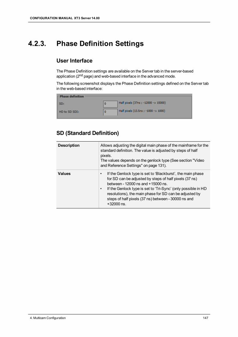
4.2.3. Phase Definition Settings
User Interface
The Phase Definition settings are available on the Server tab in the server-basedapplication (2nd page) and web-based interface in the advancedmode.
The following screenshot displays the Phase Definition settings defined on the Server tabin the web-based interface:
SD (Standard Definition)
Description Allows adjusting the digital main phase of themainframe for thestandard definition. The value is adjusted by steps of halfpixels.The values depends on the genlock type (See section "Videoand Reference Settings" on page 131).
Values • If the Genlock type is set to ‘Blackburst’, themain phasefor SD can be adjusted by steps of half pixels (37 ns)between - 12000 ns and +15000 ns.
• If the Genlock type is set to ‘Tri-Sync’ (only possible in HDresolutions), themain phase for SD can be adjusted bysteps of half pixels (37 ns) between - 30000 ns and+32000 ns.
CONFIGURATION MANUAL XT3 Server 14.00
4. MulticamConfiguration 147
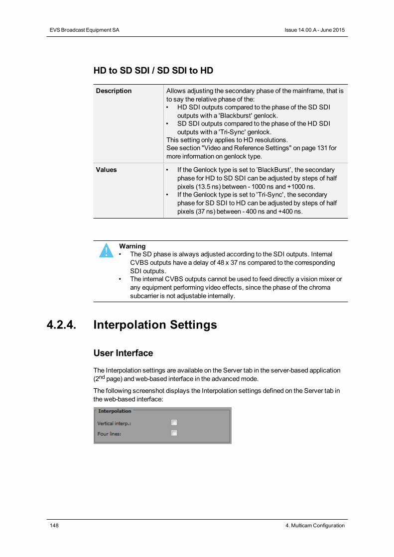
HD to SD SDI / SD SDI to HD
Description Allows adjusting the secondary phase of themainframe, that isto say the relative phase of the:• HD SDI outputs compared to the phase of the SD SDI
outputs with a 'Blackburst' genlock.• SD SDI outputs compared to the phase of the HD SDI
outputs with a 'Tri-Sync' genlock.This setting only applies to HD resolutions.See section "Video and Reference Settings" on page 131 formore information on genlock type.
Values • If the Genlock type is set to ’BlackBurst’, the secondaryphase for HD to SD SDI can be adjusted by steps of halfpixels (13.5 ns) between - 1000 ns and +1000 ns.
• If the Genlock type is set to 'Tri-Sync', the secondaryphase for SD SDI to HD can be adjusted by steps of halfpixels (37 ns) between - 400 ns and +400 ns.
Warning• The SD phase is always adjusted according to the SDI outputs. Internal
CVBS outputs have a delay of 48 x 37 ns compared to the correspondingSDI outputs.
• The internal CVBS outputs cannot be used to feed directly a visionmixer orany equipment performing video effects, since the phase of the chromasubcarrier is not adjustable internally.
4.2.4. Interpolation Settings
User Interface
The Interpolation settings are available on the Server tab in the server-based application(2nd page) and web-based interface in the advancedmode.
The following screenshot displays the Interpolation settings defined on the Server tab inthe web-based interface:
148 4. MulticamConfiguration
EVSBroadcast Equipment SA Issue 14.00.A - June 2015
General Description
The interpolation process aims at reducing the vertical jitter of the pictures that is presentduring slow-motion replays. This vertical jitter is actually caused by a violation of theframe parity when playing back the pictures at less than 100% speed.
The process consists in re-building new frames to produce amore transparent result.These frames have to be interpolated, that is calculated by making suitably weightedaverages of adjacent lines.
There are two interpolationmodes: the two-line interpolator and the four-line interpolator.They are not mutually exclusive:
• The two-line interpolator reduces the vertical jitter, but also the vertical bandwidth.
• The four-line interpolator makes it possible to have perfectly steady pictures, butreduces evenmore the vertical bandwidth.
NoteAll VTRs use interpolation in PLAY VAR mode.
Vertical Interp. (Vertical Interpolation)
Description Enables or disables the two-line interpolation process.
Values • No (default)• Yes
Four Lines
Description Enables or disables the four-line interpolation process.
Values • No (default)• Yes
4.2.5. PC LAN Settings
User Interface
The PC LAN settings allow theMTPC board of an EVS server to communicate andexchange information with other EVS hardware on a setup.
The PC LAN settings are displayed on the Server tab in the server-based application(2nd page) and web-based interface in the advancedmode.
CONFIGURATION MANUAL XT3 Server 14.00
4. MulticamConfiguration 149
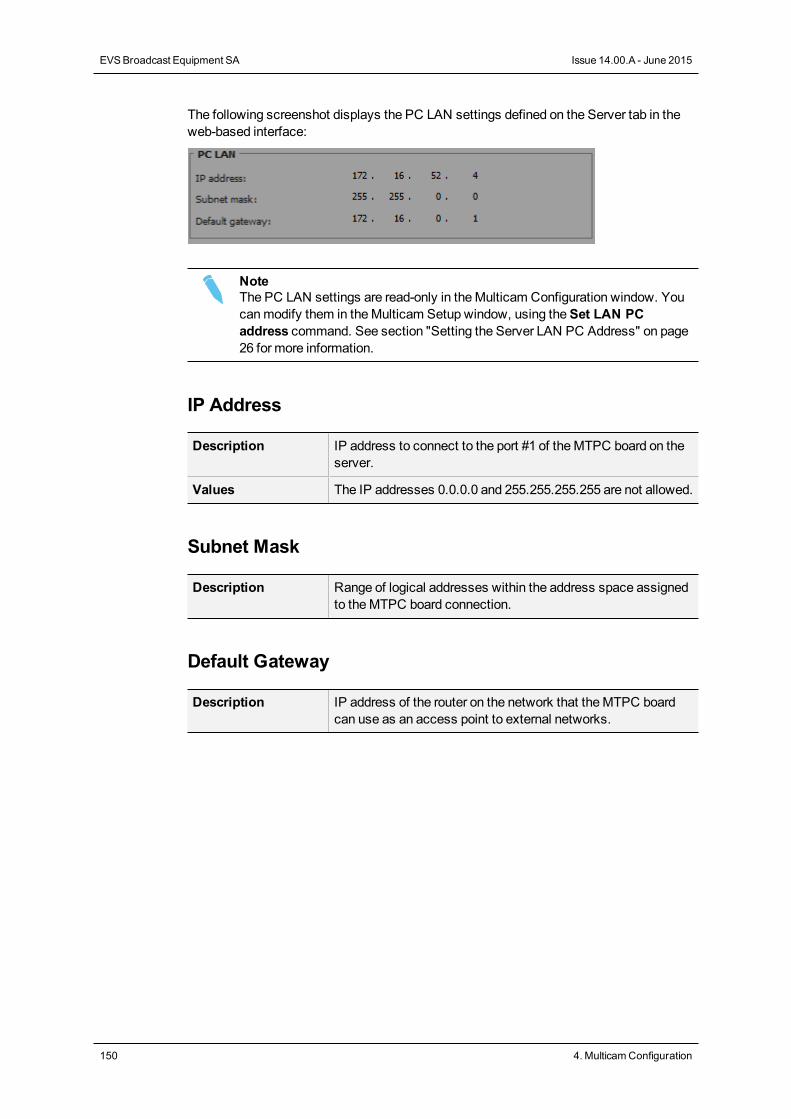
The following screenshot displays the PC LAN settings defined on the Server tab in theweb-based interface:
NoteThe PC LAN settings are read-only in theMulticam Configuration window. Youcanmodify them in theMulticam Setup window, using theSet LAN PCaddress command. See section "Setting the Server LAN PC Address" on page26 for more information.
IP Address
Description IP address to connect to the port #1 of theMTPC board on theserver.
Values The IP addresses 0.0.0.0 and 255.255.255.255 are not allowed.
Subnet Mask
Description Range of logical addresses within the address space assignedto theMTPC board connection.
Default Gateway
Description IP address of the router on the network that theMTPC boardcan use as an access point to external networks.
150 4. MulticamConfiguration
EVSBroadcast Equipment SA Issue 14.00.A - June 2015
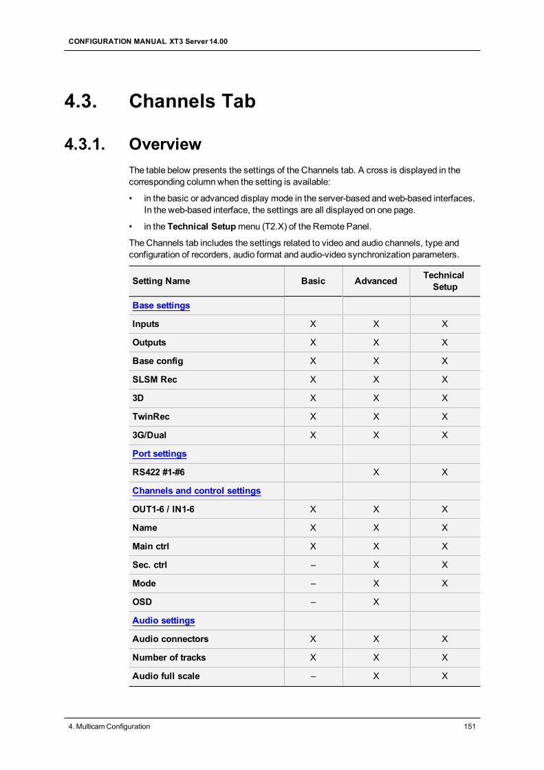
4.3. Channels Tab
4.3.1. OverviewThe table below presents the settings of the Channels tab. A cross is displayed in thecorresponding columnwhen the setting is available:
• in the basic or advanced display mode in the server-based and web-based interfaces.In the web-based interface, the settings are all displayed on one page.
• in the Technical Setupmenu (T2.X) of the Remote Panel.
The Channels tab includes the settings related to video and audio channels, type andconfiguration of recorders, audio format and audio-video synchronization parameters.
Setting Name Basic Advanced TechnicalSetup
Base settings
Inputs X X X
Outputs X X X
Base config X X X
SLSM Rec X X X
3D X X X
TwinRec X X X
3G/Dual X X X
Port settings
RS422 #1-#6 X X
Channels and control settings
OUT1-6 / IN1-6 X X X
Name X X X
Main ctrl X X X
Sec. ctrl – X X
Mode – X X
OSD – X
Audio settings
Audio connectors X X X
Number of tracks X X X
Audio full scale – X X
CONFIGURATION MANUAL XT3 Server 14.00
4. MulticamConfiguration 151
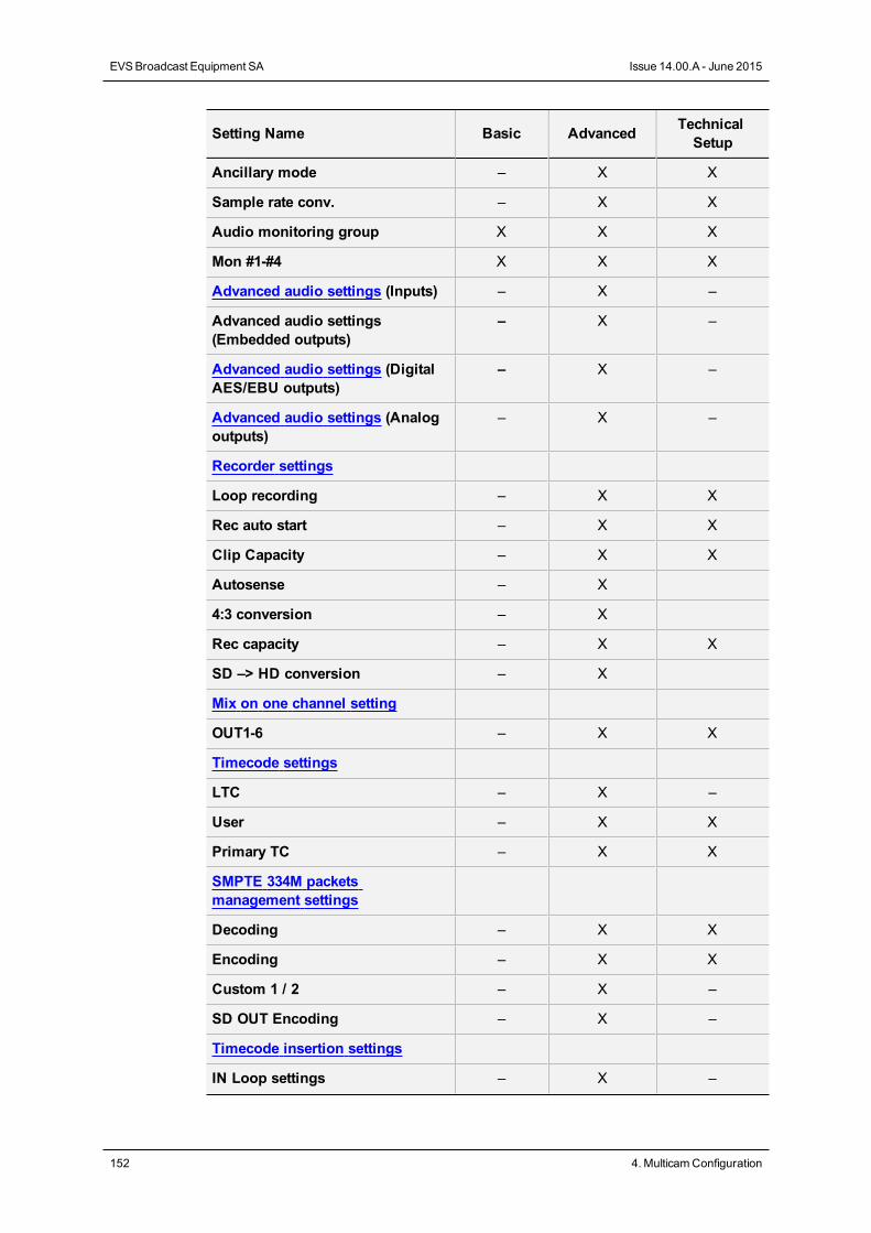
Setting Name Basic Advanced TechnicalSetup
Ancillary mode – X X
Sample rate conv. – X X
Audio monitoring group X X X
Mon #1-#4 X X X
Advanced audio settings (Inputs) – X –
Advanced audio settings(Embedded outputs)
– X –
Advanced audio settings (DigitalAES/EBU outputs)
– X –
Advanced audio settings (Analogoutputs)
– X –
Recorder settings
Loop recording – X X
Rec auto start – X X
Clip Capacity – X X
Autosense – X
4:3 conversion – X
Rec capacity – X X
SD –> HD conversion – X
Mix on one channel setting
OUT1-6 – X X
Timecode settings
LTC – X –
User – X X
Primary TC – X X
SMPTE 334M packetsmanagement settings
Decoding – X X
Encoding – X X
Custom 1 / 2 – X –
SD OUT Encoding – X –
Timecode insertion settings
IN Loop settings – X –
152 4. MulticamConfiguration
EVSBroadcast Equipment SA Issue 14.00.A - June 2015
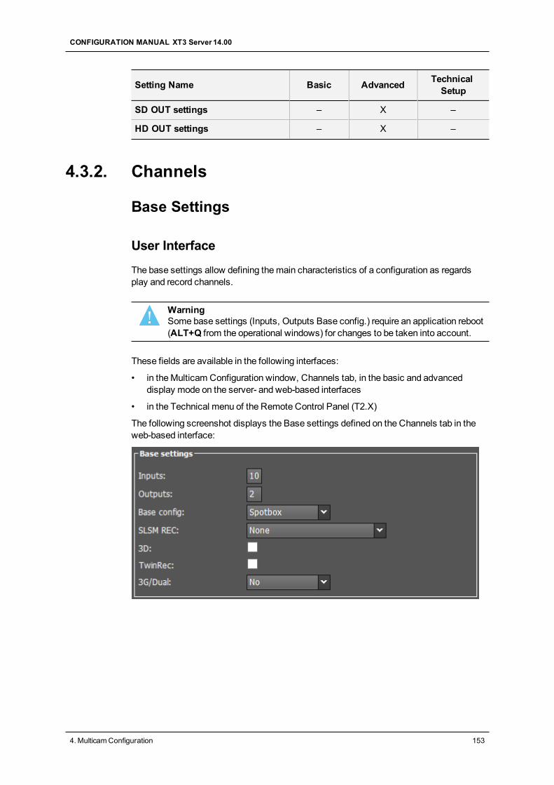
Setting Name Basic Advanced TechnicalSetup
SD OUT settings – X –
HD OUT settings – X –
4.3.2. Channels
Base Settings
User Interface
The base settings allow defining themain characteristics of a configuration as regardsplay and record channels.
WarningSome base settings (Inputs, Outputs Base config.) require an application reboot(ALT+Q from the operational windows) for changes to be taken into account.
These fields are available in the following interfaces:
• in theMulticam Configuration window, Channels tab, in the basic and advanceddisplay mode on the server- and web-based interfaces
• in the Technical menu of the Remote Control Panel (T2.X)
The following screenshot displays the Base settings defined on the Channels tab in theweb-based interface:
CONFIGURATION MANUAL XT3 Server 14.00
4. MulticamConfiguration 153
Inputs
Description Number of logical record channels in the given configuration.The partition of the disk storage between these channels, andthe advanced audio settings are automatically adapted to thenumber of record channels.
Values The number of supported channels depends on the chassis,and themode:• On XT3 6U: 0-12 (Spotbox), 1-8 (LSM)• On XT3 4U: 0-7 (Spotbox), 1-7 (LSM)See section "About Supported Configurations" on page 48 formore information on number of record channels and onsupported configurations.
Outputs
Description Number of logical play channels in the given configuration.
Values • On XT3 6U: 0-6 (Spotbox), 1-6 (LSM)• On XT3 4U: 0-4 (Spotbox), 1-3 (LSM)See section "About Supported Configurations" on page 48 formore information on number of record channels and onsupported configurations.
154 4. MulticamConfiguration
EVSBroadcast Equipment SA Issue 14.00.A - June 2015
Base Config.
Description Mode the EVS server is working in.The base configurations available depend on the server type,and on the valid license codes.
Values • Multicam LSM:mode where the EVS server is controlled by the RemoteControl Panel or from theMulticam production screens.
• Replay-Only LSM:restrictedMulticam LSMmodewithout playlistmanagement, split audio, nor support of hypermotioncameras.
• Video Delay:mode where the server is used to play out the input with avideo delay.
• Spotbox:mode where the EVS server can be controlled by industry-standard protocols: Sony BVW75, VDCP, Odetics, DD35,EVS’ AVSP, IPDP, EditRec or LinX API, or from theMulticam production screens.
• XSense:mode where the EVS server can be controlled by theXSense Remote Panel or from theMulticam productionscreens.
• Server:mode where the EVS server can only be controlled by thesupported industry-standard protocols, but not from theMulticam production screens.
Default value Multicam LSM
CONFIGURATION MANUAL XT3 Server 14.00
4. MulticamConfiguration 155
SLSM Rec
Availability This parameter is available with the license code 110.
Description Activates the slow motion recording, and allows defining thetype of SLSM recorder that is connected to the EVS server.
Values In SD:• None• Single SD SLSM 3x Alt. Parity• Single SD SLSM 3x Ident. Parity• Double SD SLSM 3x Alt. Parity• Double SD SLSM 3x Ident. ParityIn HD:• None• Single HD SLSM 2x Alt. Parity• Single HD SLSM 3x Alt. Parity• Double HD SLSM 3x Alt. Parity• Double HD SLSM 2x Alt. Parity• Triple HD SLSM 2x Alt. Parity• Single HD SLSM 6x Alt. Parity• Single HD SLSM 10x Alt. Parity• Single 3GHD SLSM 2x Alt. Parity• Double 3GHD SLSM 2x Alt. Parity• Triple 3GHD SLSM 2x Alt. Parity• Triple HD SLSM 3x Alt. Parity• Quad HD SLSM 2x Alt. Parity• Quad 3GHD SLSM 2x Alt. Parity• Single HD SLSM 4x Alt. Parity• Double HD SLSM 4x Alt. Parity• Single 3GHD SLSM 6x Alt. Parity• Double 3GHD SLSM 6x Alt. Parity• Double HD SLSM 6x Alt. ParityIn 4K:• Single HD SLSM 2x
NoteThe fault tolerance on the different phases of the super motion camera is +/-90% of one field. So there should be no delay between the different phases whenall equipments are genlocked.
156 4. MulticamConfiguration
EVSBroadcast Equipment SA Issue 14.00.A - June 2015
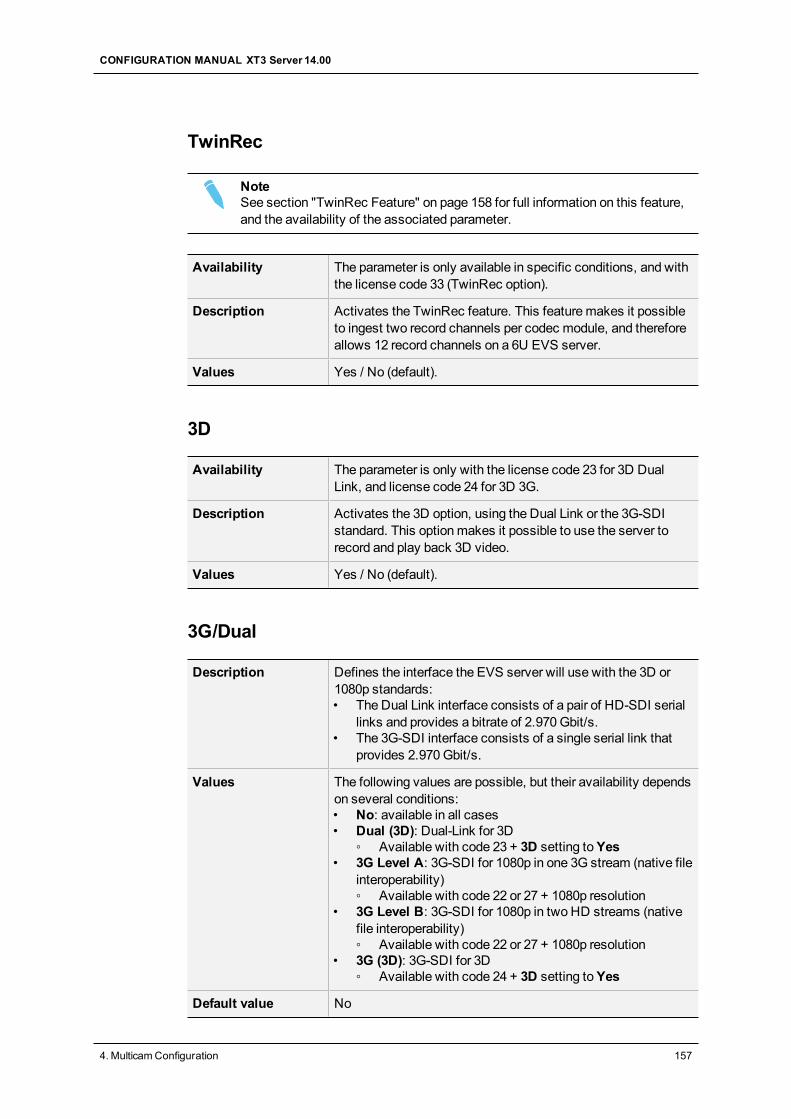
TwinRec
NoteSee section "TwinRec Feature" on page 158 for full information on this feature,and the availability of the associated parameter.
Availability The parameter is only available in specific conditions, and withthe license code 33 (TwinRec option).
Description Activates the TwinRec feature. This featuremakes it possibleto ingest two record channels per codec module, and thereforeallows 12 record channels on a 6U EVS server.
Values Yes / No (default).
3D
Availability The parameter is only with the license code 23 for 3D DualLink, and license code 24 for 3D 3G.
Description Activates the 3D option, using the Dual Link or the 3G-SDIstandard. This optionmakes it possible to use the server torecord and play back 3D video.
Values Yes / No (default).
3G/Dual
Description Defines the interface the EVS server will use with the 3D or1080p standards:• The Dual Link interface consists of a pair of HD-SDI serial
links and provides a bitrate of 2.970Gbit/s.• The 3G-SDI interface consists of a single serial link that
provides 2.970Gbit/s.
Values The following values are possible, but their availability dependson several conditions:• No: available in all cases• Dual (3D): Dual-Link for 3D
◦ Available with code 23 + 3D setting toYes• 3G Level A: 3G-SDI for 1080p in one 3G stream (native file
interoperability)◦ Available with code 22 or 27 + 1080p resolution
• 3G Level B: 3G-SDI for 1080p in two HD streams (nativefile interoperability)◦ Available with code 22 or 27 + 1080p resolution
• 3G (3D): 3G-SDI for 3D◦ Available with code 24 + 3D setting toYes
Default value No
CONFIGURATION MANUAL XT3 Server 14.00
4. MulticamConfiguration 157
WarningOnly the configurations explicitly allowed by the license codes can be started.For instance, if a user has code 22 (1080p 3G) and 23 (3D Dual-Link), he cannotstart the server in 3D 3G although he can select 3G and 3D Dual-Link in theMulticam Configuration window. To enable 3D 3G configurations to be started,code 24must be active.
NoteClips recorded with the 3G/Dual parameter in onemode (Level-A, Level-B, orDual) are playable in another mode (Level-A, Level-B, or Dual).
TwinRec Feature
Introduction
The TwinRec feature allows the use of both record channels of each codec module.Therefore, you can ingest two record channels per codec module, whichmeans 12 recordchannels on a 6U EVS server fitted with 3 codec boards. This feature is mainly applicableto entertainment shows.
When you use the TwinRec feature, you will wire all main (J8) and secondary (J5) recordchannels, but set the number of inputs to 6 (not to 12) as only themain channels aredisplayed in theMulticam Configuration window. Consequently, the configuration of themain channels are automatically applied to the corresponding secondary channels.
The 12 recorded channels could then be streamed through a 10GbE connection directly toan external storage or nearline, using Xsquare.
The TwinRec feature can be activated via the TwinRec parameter available in theChannels tab, Base Settings section. See section "Base Settings" on page 153.
Availability
The TwinRec feature, and its associated parameter, are available and displayed in thefollowing conditions:
• on the XT3 6U and XT3 4U servers.
• with valid license codes 33 (TwinRec) and 23 (3D Dual)
• with aSpotbox base configuration (Base Settings section)
The TwinRec parameter can only be activated when all the following conditions aremet:
• TheResolution parameter is set to 720p or 1080i (Server tab, Video and Referencesection).
• The Intra only or Intra + Proxymode is active (Server tab, Codec section).
• The EVS server runs a 6 IN 0 OUT or 4 IN 0 OUT channel configuration (BaseSettings section).
158 4. MulticamConfiguration
EVSBroadcast Equipment SA Issue 14.00.A - June 2015
• The 3D parameter is set toNo (Base Settings section).
• The 3G/Dual parameter is set toDual (Base Settings section).
• In theSLSM settings, theNumber of cameras parameter is set to 0 (Base Settingssection).
A message will warn the user if one of the above-mentioned conditions is not fulfilled.
Limitations
The following limitations are applicable to the TwinRec feature as the configuration of themain channels is applied to the corresponding secondary channels:
• The TwinRec function is only available in HD only, in intra-frame codecs.
• The audio is only recorded on themain channels, not on the secondary channels.
When the feeds are exported to an external storage, Xsquare will however duplicatethe audio of themain channel to the secondary channel.
• The embedded audio is mapped to themain channel.
• The audiomonitoring is performed on themain channels only.
• Only themain channels can be seen in the internal multiviewer.
• In the Clip screen, the clips of the secondary channels are hidden behind the clips ofthemain channels.
• WhenGPIs are used, the behavior of the secondary channel will be exactly the sameas that of the associatedmain channel.
Port Settings
User Interface
The port settings allow assigning the RS422 ports to the various external controllers (EVSor third-party) that will communicate with the EVS server.
These fields are available in the following interfaces:
• in theMulticam Configuration window, Channels tab, in the basic and advanceddisplay mode of the server- and web-based interfaces
• in the Technical menu of the Remote Control Panel (T2.X)
CONFIGURATION MANUAL XT3 Server 14.00
4. MulticamConfiguration 159
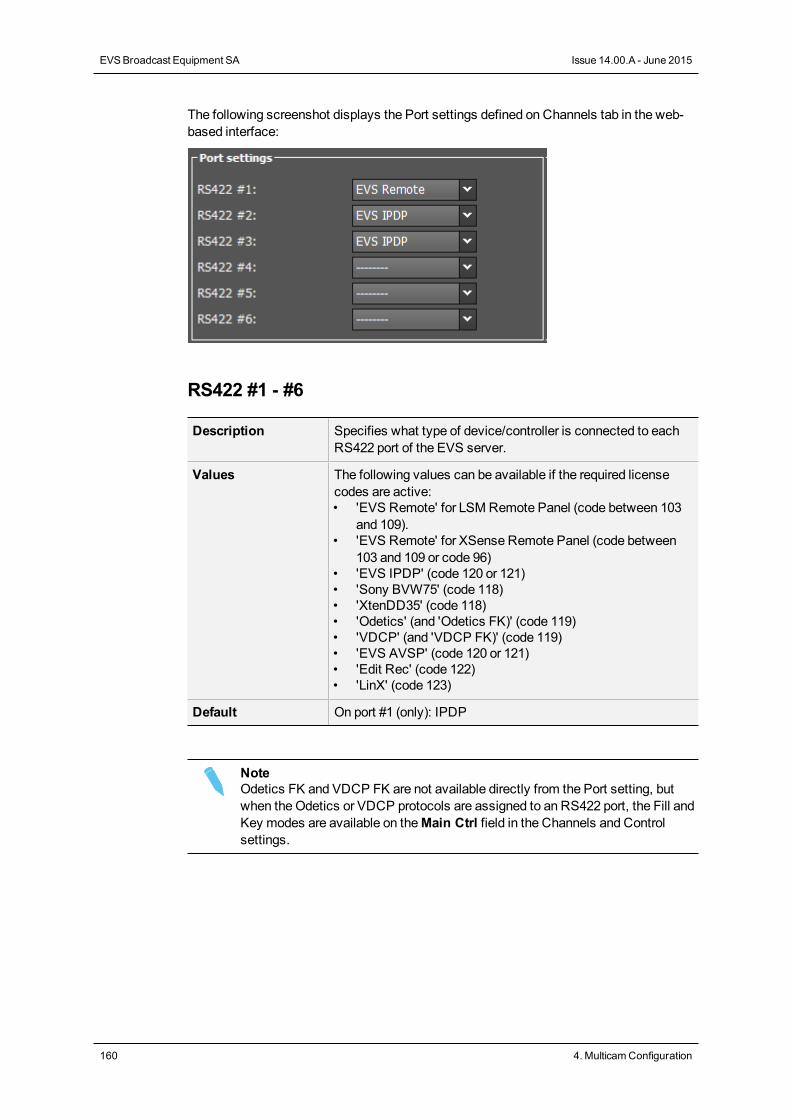
The following screenshot displays the Port settings defined on Channels tab in the web-based interface:
RS422 #1 - #6
Description Specifies what type of device/controller is connected to eachRS422 port of the EVS server.
Values The following values can be available if the required licensecodes are active:• 'EVS Remote' for LSM Remote Panel (code between 103
and 109).• 'EVS Remote' for XSense Remote Panel (code between
103 and 109 or code 96)• 'EVS IPDP' (code 120 or 121)• 'Sony BVW75' (code 118)• 'XtenDD35' (code 118)• 'Odetics' (and 'Odetics FK)' (code 119)• 'VDCP' (and 'VDCP FK)' (code 119)• 'EVS AVSP' (code 120 or 121)• 'Edit Rec' (code 122)• 'LinX' (code 123)
Default On port #1 (only): IPDP
NoteOdetics FK and VDCP FK are not available directly from the Port setting, butwhen theOdetics or VDCP protocols are assigned to an RS422 port, the Fill andKey modes are available on theMain Ctrl field in the Channels and Controlsettings.
160 4. MulticamConfiguration
EVSBroadcast Equipment SA Issue 14.00.A - June 2015
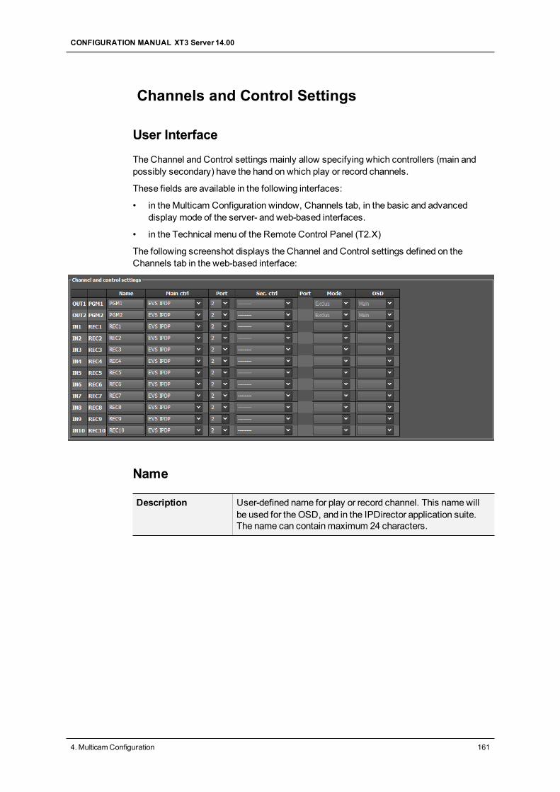
Channels and Control Settings
User Interface
The Channel and Control settings mainly allow specifying which controllers (main andpossibly secondary) have the hand on which play or record channels.
These fields are available in the following interfaces:
• in theMulticam Configuration window, Channels tab, in the basic and advanceddisplay mode of the server- and web-based interfaces.
• in the Technical menu of the Remote Control Panel (T2.X)
The following screenshot displays the Channel and Control settings defined on theChannels tab in the web-based interface:
Name
Description User-defined name for play or record channel. This namewillbe used for the OSD, and in the IPDirector application suite.The name can contain maximum 24 characters.
CONFIGURATION MANUAL XT3 Server 14.00
4. MulticamConfiguration 161
Main ctrl (Main Controller)
Description Name of themain device/controller allowed to control the givenplay or record channel.
Values For a controller to be available in the list of values, it must firstbe assigned to an RS422 port in the port settings.In addition, rules specific to each controller apply to theassignment of the controller (used alone or in combinationswith other controllers) to play or/and record channels. Seesection "Rules for Controller Assignment" on page 163 for moreinformation.An error message will be displayed to warn you in case of awrong protocol selection or protocol combination, and the fieldsthat contain errors will be highlighted in red.
Sec. ctrl (Secondary Controller)
Description Name of themain device/controller allowed to control the givenplay or record channel.
Values For a controller to be available in the list of values, it must firstbe assigned to an RS422 port in the port settings.In addition, rules specific to each controller apply to theassignment of the controller (used alone or in combinationswith other controllers) to play or/and record channels. Seesection "Rules for Controller Assignment" on page 163 for moreinformation.An error message will be displayed to warn you in case of awrong protocol selection or protocol combination, and the fieldsthat contain errors will be highlighted in red.
Mode
Description Specifies how the control on the given play or record channel ismanaged between themain and secondary controllers, when itis possible to definemain and secondary controllers.
Values Two control modes are possible:• Exclusive mode:
Themain controller can decide at any time to pass thecontrol to, or to retrieve the control from the secondarycontroller.
• Parallel mode:Any of both controllers can take the control as long as theother controller is not executing a command. The controlcan thus be freely passed on from one controller to theother.
162 4. MulticamConfiguration
EVSBroadcast Equipment SA Issue 14.00.A - June 2015
OSD
Description Specifies which device (main or secondary controller) willmanage theOSD display characters in parallel mode.
Values Two values are possible:• Main: TheOSD display is managed by themain controller.• Sec.: TheOSD display is managed by the secondary
controller.
Rules for Controller Assignment
Main Rules for XT3 server
On an XT3 server, the followingmain rules are applicable:
• In aMulticam LSM base configuration:
◦ All Remote Panels must be the first in the list of main controllers, without gap. It isnot allowed to have another controller preceding a Remote Panel in this list.
◦ Other controllers can be assigned as secondary controllers to PGMs taking intoaccount the protocol-specific rules.
◦ Nomore than 4 play channels on an EVS server can be assigned to RemotePanels, and nomore than 3 play channels can be assigned to one Remote Panel.
◦ Only a Remote Panel (no other controller) can be assigned to a REC channel as amain controller.
◦ No secondary controller can be assigned to a REC channel.
• In a Spotbox or Server base configuration:
◦ A Remote Panel is not allowed.
◦ Controllers other than the EVS Remote can be assigned to play or recordchannels, taking into account the protocol-specific rules on controller use andcombinations.
CONFIGURATION MANUAL XT3 Server 14.00
4. MulticamConfiguration 163
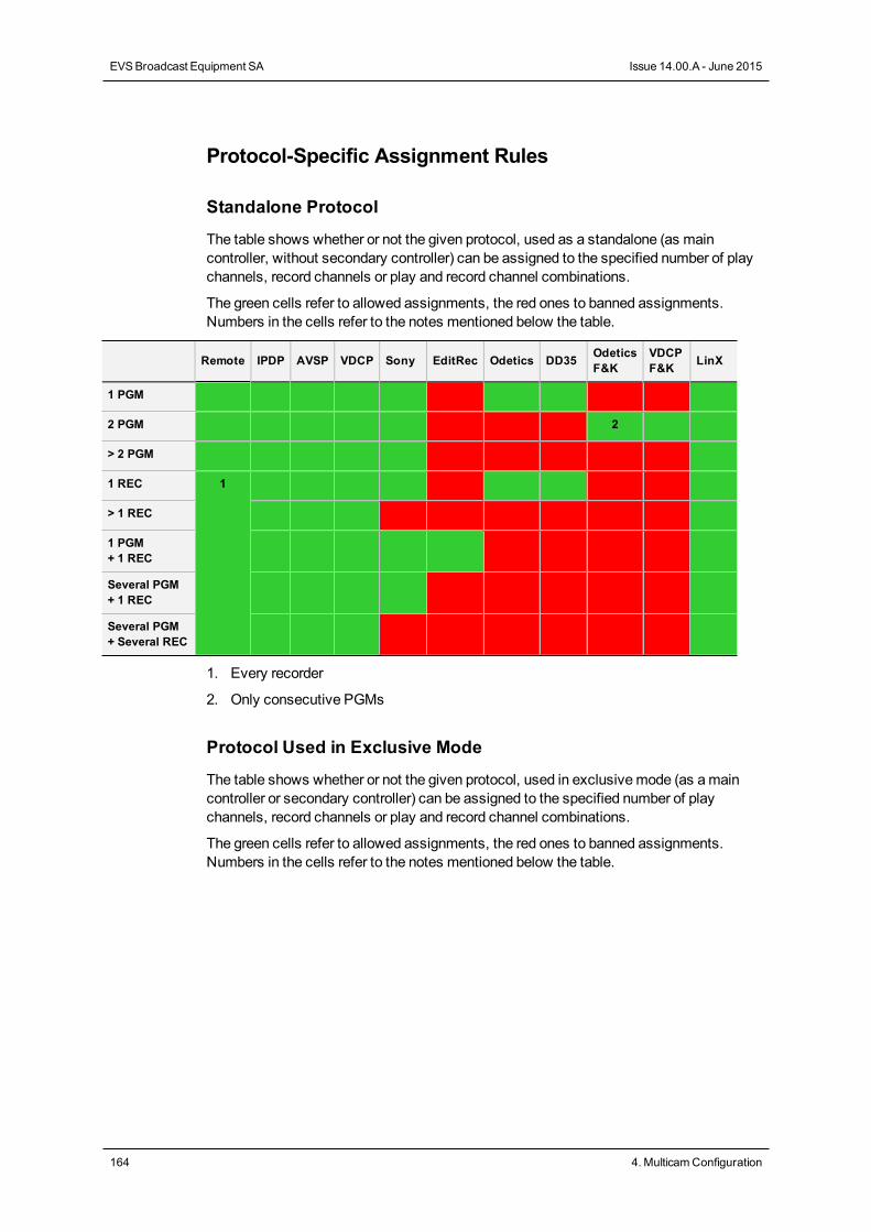
Protocol-Specific Assignment Rules
Standalone Protocol
The table shows whether or not the given protocol, used as a standalone (as maincontroller, without secondary controller) can be assigned to the specified number of playchannels, record channels or play and record channel combinations.
The green cells refer to allowed assignments, the red ones to banned assignments.Numbers in the cells refer to the notes mentioned below the table.
Remote IPDP AVSP VDCP Sony EditRec Odetics DD35 OdeticsF&K
VDCPF&K LinX
1 PGM
2 PGM 2
> 2 PGM
1 REC 1
> 1 REC
1 PGM+ 1 REC
Several PGM+ 1 REC
Several PGM+ Several REC
1. Every recorder
2. Only consecutive PGMs
Protocol Used in Exclusive Mode
The table shows whether or not the given protocol, used in exclusivemode (as amaincontroller or secondary controller) can be assigned to the specified number of playchannels, record channels or play and record channel combinations.
The green cells refer to allowed assignments, the red ones to banned assignments.Numbers in the cells refer to the notes mentioned below the table.
164 4. MulticamConfiguration
EVSBroadcast Equipment SA Issue 14.00.A - June 2015
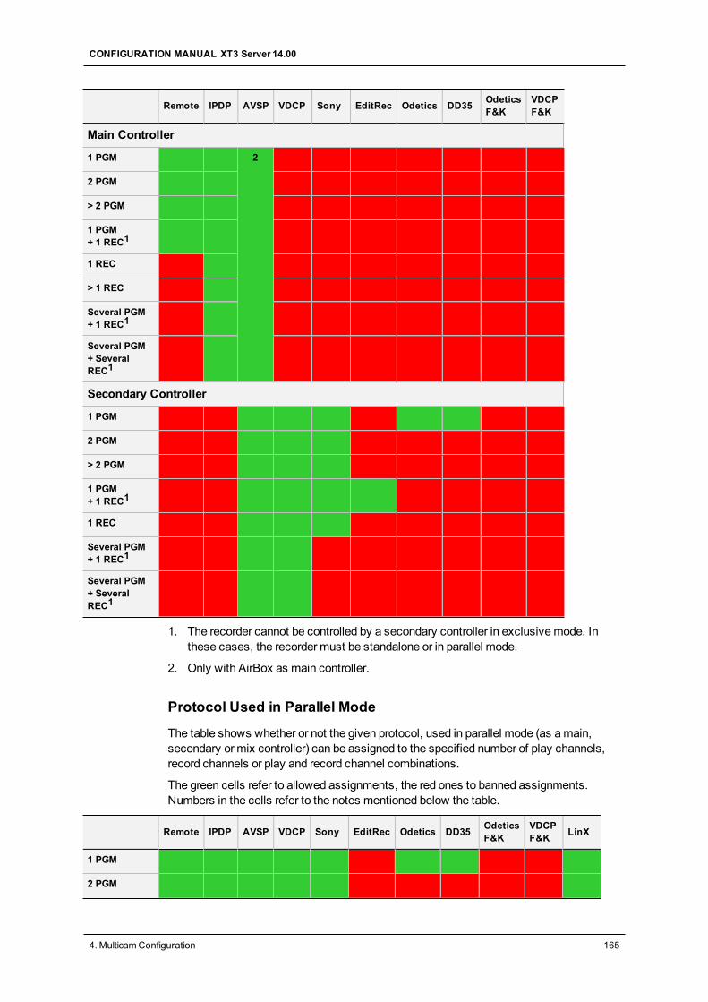
Remote IPDP AVSP VDCP Sony EditRec Odetics DD35 OdeticsF&K
VDCPF&K
Main Controller
1 PGM 2
2 PGM
> 2 PGM
1 PGM+ 1 REC1
1 REC
> 1 REC
Several PGM+ 1 REC1
Several PGM+ SeveralREC1
Secondary Controller
1 PGM
2 PGM
> 2 PGM
1 PGM+ 1 REC1
1 REC
Several PGM+ 1 REC1
Several PGM+ SeveralREC1
1. The recorder cannot be controlled by a secondary controller in exclusivemode. Inthese cases, the recorder must be standalone or in parallel mode.
2. Only with AirBox as main controller.
Protocol Used in Parallel Mode
The table shows whether or not the given protocol, used in parallel mode (as amain,secondary or mix controller) can be assigned to the specified number of play channels,record channels or play and record channel combinations.
The green cells refer to allowed assignments, the red ones to banned assignments.Numbers in the cells refer to the notes mentioned below the table.
Remote IPDP AVSP VDCP Sony EditRec Odetics DD35 OdeticsF&K
VDCPF&K LinX
1 PGM
2 PGM
CONFIGURATION MANUAL XT3 Server 14.00
4. MulticamConfiguration 165
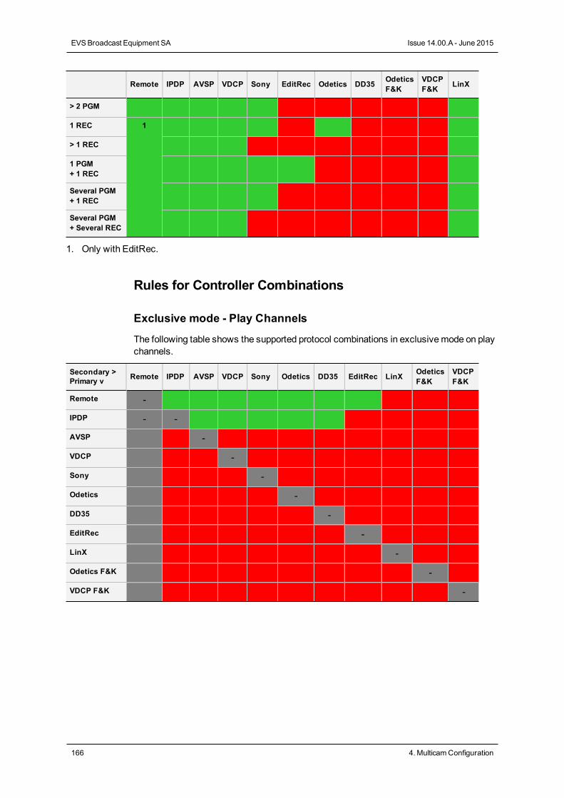
Remote IPDP AVSP VDCP Sony EditRec Odetics DD35 OdeticsF&K
VDCPF&K LinX
> 2 PGM
1 REC 1
> 1 REC
1 PGM+ 1 REC
Several PGM+ 1 REC
Several PGM+ Several REC
1. Only with EditRec.
Rules for Controller Combinations
Exclusive mode - Play Channels
The following table shows the supported protocol combinations in exclusivemode on playchannels.
Secondary >Primary v Remote IPDP AVSP VDCP Sony Odetics DD35 EditRec LinX Odetics
F&KVDCPF&K
Remote -
IPDP - -
AVSP -
VDCP -
Sony -
Odetics -
DD35 -
EditRec -
LinX -
Odetics F&K -
VDCP F&K -
166 4. MulticamConfiguration
EVSBroadcast Equipment SA Issue 14.00.A - June 2015
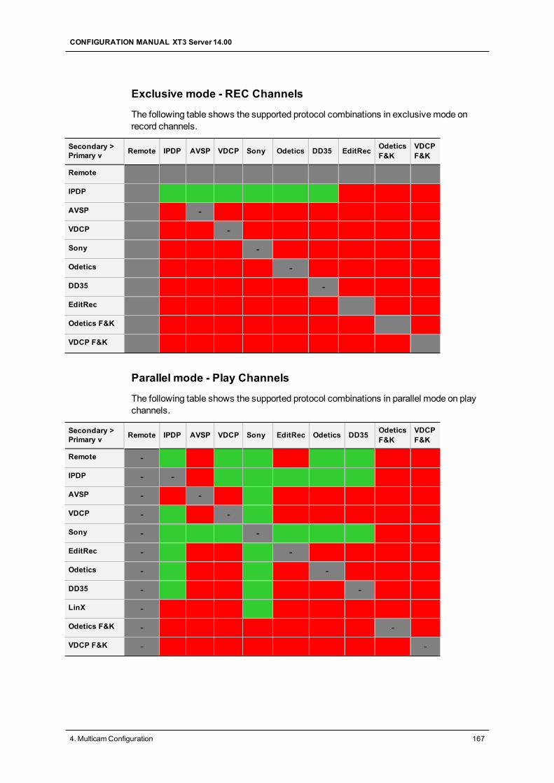
Exclusive mode - REC Channels
The following table shows the supported protocol combinations in exclusivemode onrecord channels.
Secondary >Primary v Remote IPDP AVSP VDCP Sony Odetics DD35 EditRec Odetics
F&KVDCPF&K
Remote
IPDP
AVSP -
VDCP -
Sony -
Odetics -
DD35 -
EditRec
Odetics F&K
VDCP F&K
Parallel mode - Play Channels
The following table shows the supported protocol combinations in parallel mode on playchannels.
Secondary >Primary v Remote IPDP AVSP VDCP Sony EditRec Odetics DD35 Odetics
F&KVDCPF&K
Remote -
IPDP - -
AVSP - -
VDCP - -
Sony - -
EditRec - -
Odetics - -
DD35 - -
LinX -
Odetics F&K - -
VDCP F&K - -
CONFIGURATION MANUAL XT3 Server 14.00
4. MulticamConfiguration 167
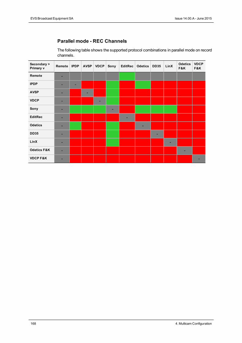
Parallel mode - REC Channels
The following table shows the supported protocol combinations in parallel mode on recordchannels.
Secondary >Primary v Remote IPDP AVSP VDCP Sony EditRec Odetics DD35 LinX Odetics
F&KVDCPF&K
Remote -
IPDP - -
AVSP - -
VDCP - -
Sony - -
EditRec - -
Odetics - -
DD35 - -
LinX - -
Odetics F&K - -
VDCP F&K - -
168 4. MulticamConfiguration
EVSBroadcast Equipment SA Issue 14.00.A - June 2015
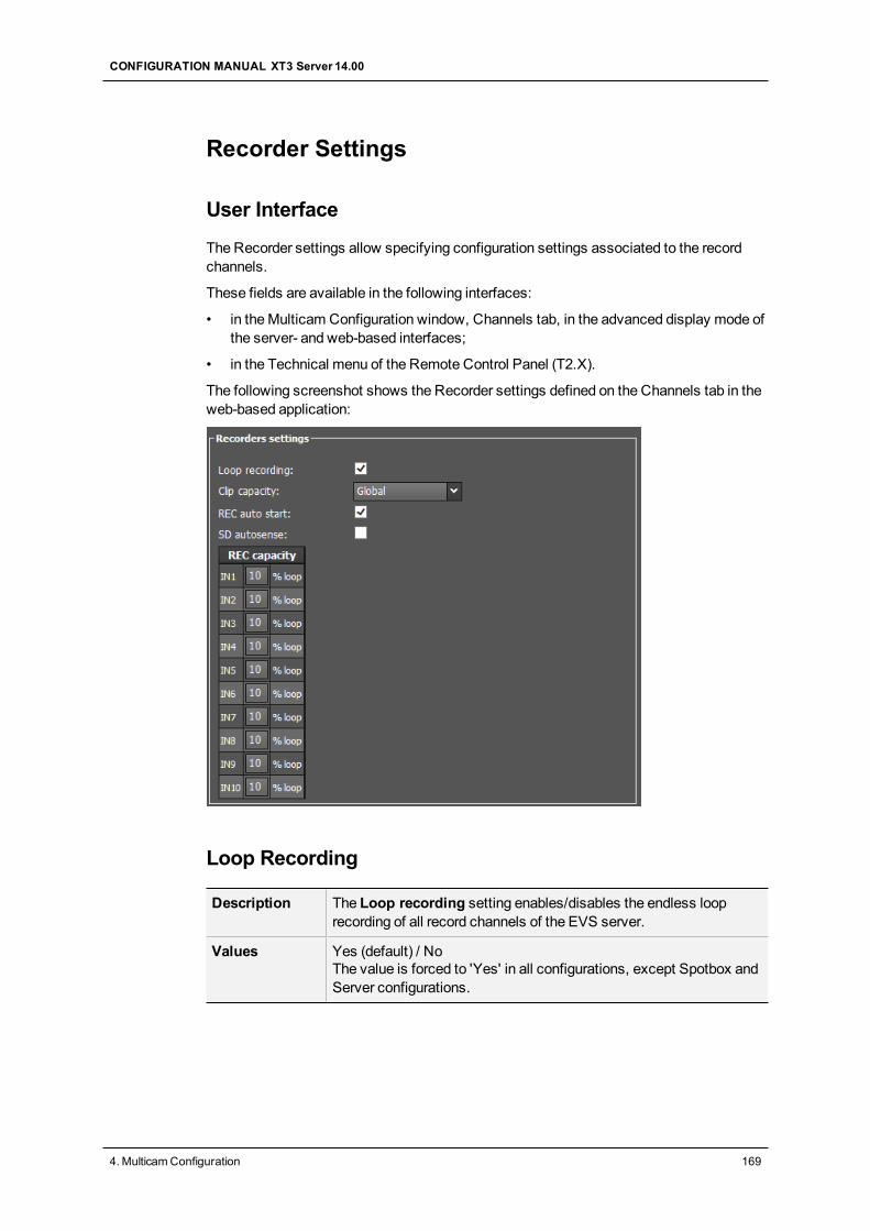
Recorder Settings
User Interface
The Recorder settings allow specifying configuration settings associated to the recordchannels.
These fields are available in the following interfaces:
• in theMulticam Configuration window, Channels tab, in the advanced display mode ofthe server- and web-based interfaces;
• in the Technical menu of the Remote Control Panel (T2.X).
The following screenshot shows the Recorder settings defined on the Channels tab in theweb-based application:
Loop Recording
Description The Loop recording setting enables/disables the endless looprecording of all record channels of the EVS server.
Values Yes (default) / NoThe value is forced to 'Yes' in all configurations, except Spotbox andServer configurations.
CONFIGURATION MANUAL XT3 Server 14.00
4. MulticamConfiguration 169
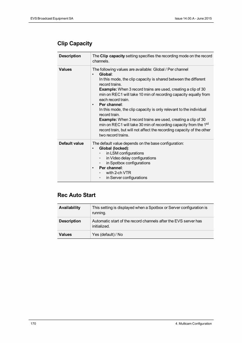
Clip Capacity
Description TheClip capacity setting specifies the recordingmode on the recordchannels.
Values The following values are available: Global / Per channel• Global:
In this mode, the clip capacity is shared between the differentrecord trains.Example:When 3 record trains are used, creating a clip of 30min on REC1will take 10min of recording capacity equally fromeach record train.
• Per channel:In this mode, the clip capacity is only relevant to the individualrecord train.Example:When 3 record trains are used, creating a clip of 30min on REC1will take 30min of recording capacity from the 1strecord train, but will not affect the recording capacity of the othertwo record trains.
Default value The default value depends on the base configuration:• Global (locked):
◦ in LSM configurations◦ in Video delay configurations◦ in Spotbox configurations
• Per channel:◦ with 2-ch VTR◦ in Server configurations
Rec Auto Start
Availability This setting is displayed when a Spotbox or Server configuration isrunning.
Description Automatic start of the record channels after the EVS server hasinitialized.
Values Yes (default) / No
170 4. MulticamConfiguration
EVSBroadcast Equipment SA Issue 14.00.A - June 2015
SD Autosense
WarningA change to this parameter requires an application reboot (ALT+Q from theoperational windows) to be taken into account.
Availability This setting is available in the following conditions:• with all HD codecs, and all multi-essence configurations.• when an HD resolution is selected in the open configuration.
Description The SD Autosense setting allows Multicam to automatically detectand upscale an SD feed and record it in the HD codec selected in theopen configuration.
Values Yes / No (default)
Limitations When the SD Autosense setting is enabled, the following featuresare not supported on the EVS server:• Replace function (with internal loop in playlist)• SHIFT + LOOP on the LSM Remote Panel• Paint function• Target Track function• Internal offside line
4:3 Conversion
Availability This setting is only available when the SD Autosense setting isenabled.
Description The 4:3 conversion setting allows users to specify how Multicamwill convert the source aspect ratio when:• Multicam detects the source aspect ratio is 4:3 full frame.
and• Multicam is configured tomanage the conversion automatically
(SD->HD conversion setting is set toAuto).
Values The following values are possible:• Pillarbox: Left and right stripes are added to the source video to
display it in a 16:9 pillar box aspect ratio.• Crop: Top and bottom ends of the source video are cropped to
display it in a 16:9 full frame aspect ratio.
Default value Pillarbox
CONFIGURATION MANUAL XT3 Server 14.00
4. MulticamConfiguration 171
REC Capacity
WarningA change to this parameter requires an application reboot (ALT+Q from theoperational windows) to be taken into account.
Description This parameter contains two types of information on the specifiedrecorder:Recording Capacity: XX% percentage of the disk space allocatedto each channel.Loop / No Loop: indicates whether the Loop Recording parameteris enabled or not.
Values The following values are possible:• Recording Capacity: The value is defined by the user.
The total of all values must not exceed 100%.By default, the recording capacity is evenly distributed among allrecorders.Example: In a 2 REC 4 PLAY configuration, the recordingcapacity will be 50% for each recorder by default.
• Loop / No Loop:• The value directly depends on the Loop Recording setting:
◦ If the Loop Recoding is enabled, the value will be 'Loop'.◦ If the Loop Recording is disabled, the value will be 'No Loop'.
172 4. MulticamConfiguration
EVSBroadcast Equipment SA Issue 14.00.A - June 2015
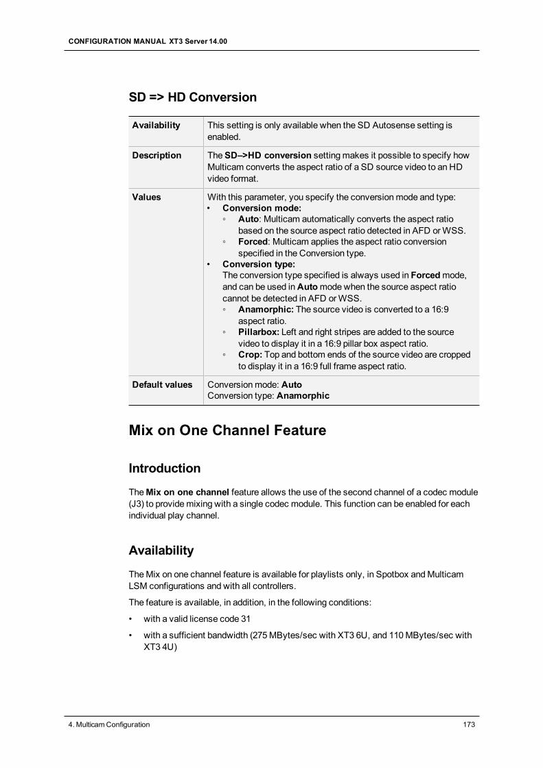
SD => HD Conversion
Availability This setting is only available when the SD Autosense setting isenabled.
Description TheSD–>HD conversion settingmakes it possible to specify howMulticam converts the aspect ratio of a SD source video to an HDvideo format.
Values With this parameter, you specify the conversionmode and type:• Conversion mode:
◦ Auto: Multicam automatically converts the aspect ratiobased on the source aspect ratio detected in AFD orWSS.
◦ Forced: Multicam applies the aspect ratio conversionspecified in the Conversion type.
• Conversion type:The conversion type specified is always used in Forcedmode,and can be used inAutomodewhen the source aspect ratiocannot be detected in AFD orWSS.◦ Anamorphic: The source video is converted to a 16:9
aspect ratio.◦ Pillarbox: Left and right stripes are added to the source
video to display it in a 16:9 pillar box aspect ratio.◦ Crop: Top and bottom ends of the source video are cropped
to display it in a 16:9 full frame aspect ratio.
Default values Conversionmode: AutoConversion type: Anamorphic
Mix on One Channel Feature
Introduction
TheMix on one channel feature allows the use of the second channel of a codec module(J3) to providemixing with a single codec module. This function can be enabled for eachindividual play channel.
Availability
TheMix on one channel feature is available for playlists only, in Spotbox andMulticamLSM configurations and with all controllers.
The feature is available, in addition, in the following conditions:
• with a valid license code 31
• with a sufficient bandwidth (275MBytes/sec with XT3 6U, and 110MBytes/sec withXT3 4U)
CONFIGURATION MANUAL XT3 Server 14.00
4. MulticamConfiguration 173
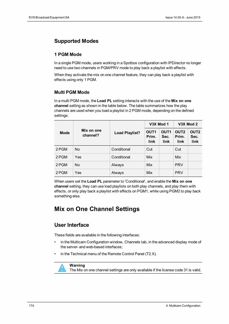
Supported Modes
1 PGMMode
In a single PGMmode, users working in a Spotbox configuration with IPDirector no longerneed to use two channels in PGM/PRV mode to play back a playlist with effects.
When they activate themix on one channel feature, they can play back a playlist witheffects using only 1 PGM.
Multi PGMMode
In amulti PGMmode, the Load PL setting interacts with the use of theMix on onechannel setting as shown in the table below. The table summarizes how the playchannels are used when you load a playlist in 2 PGMmode, depending on the definedsettings:
Mode Mix on onechannel? Load Playlist?
V3X Mod 1 V3X Mod 2
OUT1Prim.link
OUT1Sec.link
OUT2Prim.link
OUT2Sec.link
2 PGM No Conditional Cut Cut
2 PGM Yes Conditional Mix Mix
2 PGM No Always Mix PRV
2 PGM Yes Always Mix PRV
When users set the Load PL parameter to 'Conditional', and enable theMix on onechannel setting, they can use load playlists on both play channels, and play them witheffects, or only play back a playlist with effects on PGM1, while using PGM2 to play backsomething else.
Mix on One Channel Settings
User Interface
These fields are available in the following interfaces:
• in theMulticam Configuration window, Channels tab, in the advanced display mode ofthe server- and web-based interfaces;
• in the Technical menu of the Remote Control Panel (T2.X).
WarningTheMix on one channel settings are only available if the license code 31 is valid.
174 4. MulticamConfiguration
EVSBroadcast Equipment SA Issue 14.00.A - June 2015
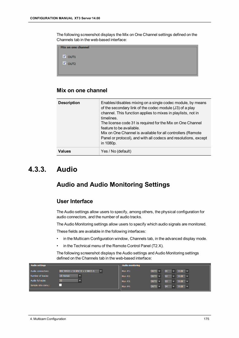
The following screenshot displays theMix onOneChannel settings defined on theChannels tab in the web-based interface:
Mix on one channel
Description Enables/disables mixing on a single codec module, by meansof the secondary link of the codec module (J3) of a playchannel. This function applies tomixes in playlists, not intimelines.The license code 31 is required for theMix onOneChannelfeature to be available.Mix onOneChannel is available for all controllers (RemotePanel or protocol), and with all codecs and resolutions, exceptin 1080p.
Values Yes / No (default)
4.3.3. Audio
Audio and Audio Monitoring Settings
User Interface
The Audio settings allow users to specify, among others, the physical configuration foraudio connectors, and the number of audio tracks.
The AudioMonitoring settings allow users to specify which audio signals aremonitored.
These fields are available in the following interfaces:
• in theMulticam Configuration window, Channels tab, in the advanced display mode.
• in the Technical menu of the Remote Control Panel (T2.X).
The following screenshot displays the Audio settings and AudioMonitoring settingsdefined on the Channels tab in the web-based interface:
CONFIGURATION MANUAL XT3 Server 14.00
4. MulticamConfiguration 175
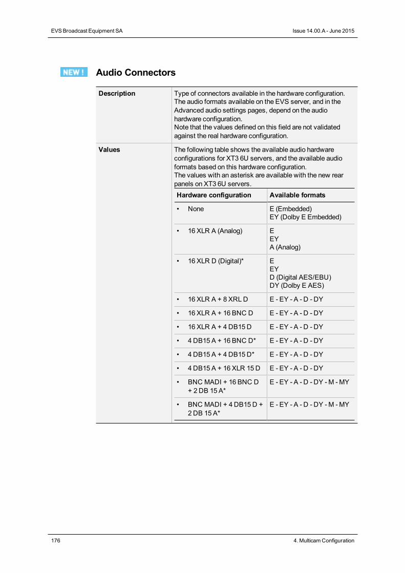
Audio Connectors
Description Type of connectors available in the hardware configuration.The audio formats available on the EVS server, and in theAdvanced audio settings pages, depend on the audiohardware configuration.Note that the values defined on this field are not validatedagainst the real hardware configuration.
Values The following table shows the available audio hardwareconfigurations for XT3 6U servers, and the available audioformats based on this hardware configuration.The values with an asterisk are available with the new rearpanels on XT3 6U servers.Hardware configuration Available formats
• None E (Embedded)EY (Dolby E Embedded)
• 16 XLR A (Analog) EEYA (Analog)
• 16 XLR D (Digital)* EEYD (Digital AES/EBU)DY (Dolby E AES)
• 16 XLR A + 8 XRLD E - EY - A - D - DY
• 16 XLR A + 16 BNC D E - EY - A - D - DY
• 16 XLR A + 4DB15D E - EY - A - D - DY
• 4 DB15 A + 16 BNC D* E - EY - A - D - DY
• 4 DB15 A + 4DB15D* E - EY - A - D - DY
• 4 DB15 A + 16 XLR 15D E - EY - A - D - DY
• BNC MADI + 16 BNC D+ 2DB 15 A*
E - EY - A - D - DY -M -MY
• BNC MADI + 4 DB15D +2DB 15 A*
E - EY - A - D - DY -M -MY
176 4. MulticamConfiguration
EVSBroadcast Equipment SA Issue 14.00.A - June 2015
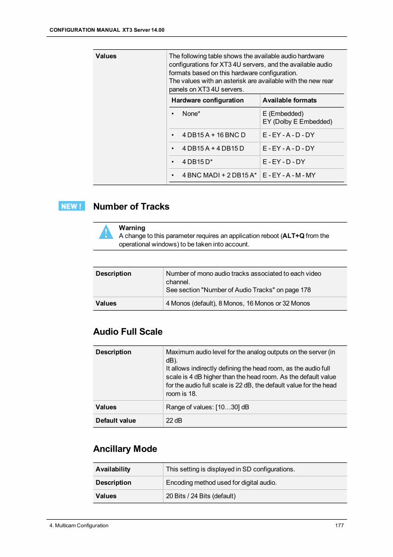
Values The following table shows the available audio hardwareconfigurations for XT3 4U servers, and the available audioformats based on this hardware configuration.The values with an asterisk are available with the new rearpanels on XT3 4U servers.Hardware configuration Available formats
• None* E (Embedded)EY (Dolby E Embedded)
• 4 DB15 A + 16 BNC D E - EY - A - D - DY
• 4 DB15 A + 4DB15D E - EY - A - D - DY
• 4 DB15D* E - EY - D - DY
• 4 BNC MADI + 2 DB15 A* E - EY - A -M -MY
Number of Tracks
WarningA change to this parameter requires an application reboot (ALT+Q from theoperational windows) to be taken into account.
Description Number of mono audio tracks associated to each videochannel.See section "Number of Audio Tracks" on page 178
Values 4Monos (default), 8 Monos, 16Monos or 32Monos
Audio Full Scale
Description Maximum audio level for the analog outputs on the server (indB).It allows indirectly defining the head room, as the audio fullscale is 4 dB higher than the head room. As the default valuefor the audio full scale is 22 dB, the default value for the headroom is 18.
Values Range of values: [10…30] dB
Default value 22 dB
Ancillary Mode
Availability This setting is displayed in SD configurations.
Description Encodingmethod used for digital audio.
Values 20 Bits / 24 Bits (default)
CONFIGURATION MANUAL XT3 Server 14.00
4. MulticamConfiguration 177
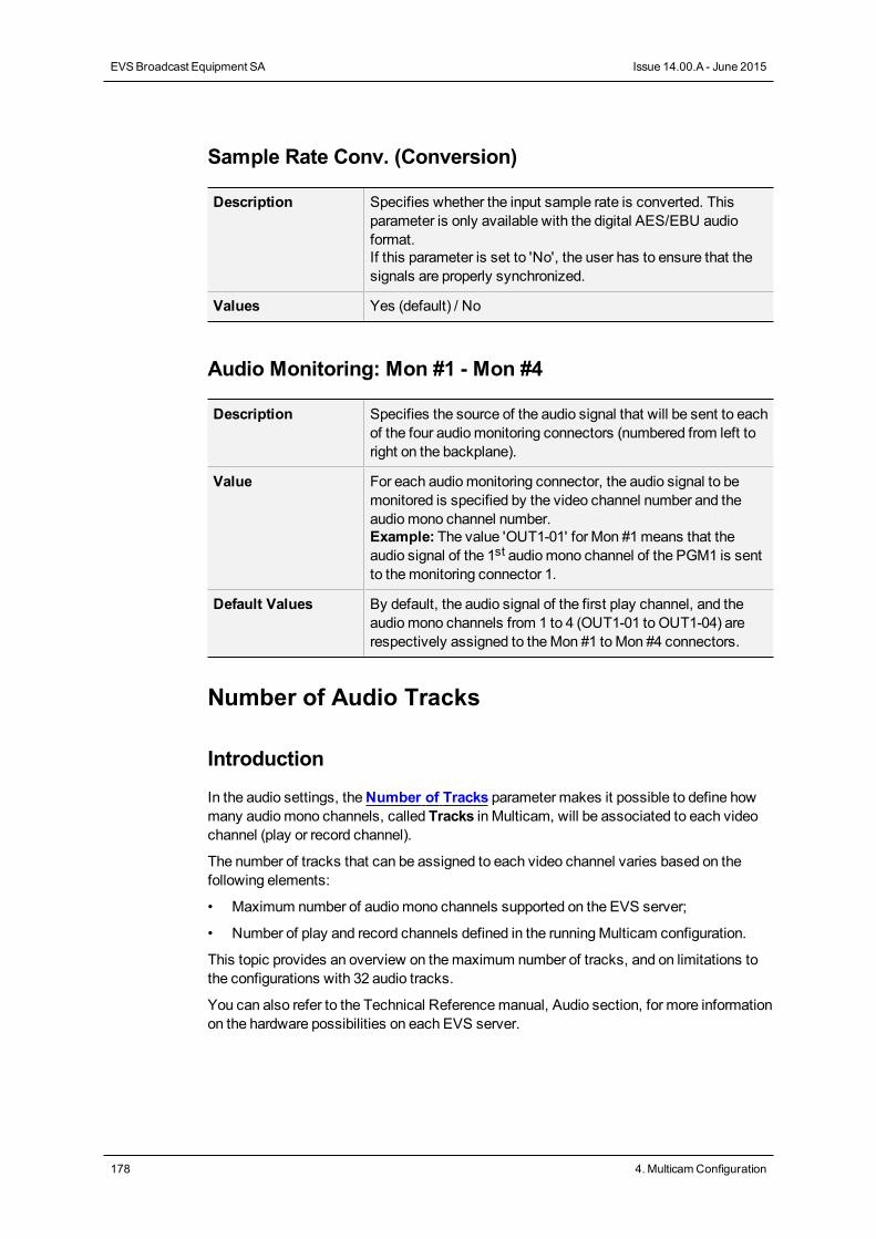
Sample Rate Conv. (Conversion)
Description Specifies whether the input sample rate is converted. Thisparameter is only available with the digital AES/EBU audioformat.If this parameter is set to 'No', the user has to ensure that thesignals are properly synchronized.
Values Yes (default) / No
Audio Monitoring: Mon #1 - Mon #4
Description Specifies the source of the audio signal that will be sent to eachof the four audiomonitoring connectors (numbered from left toright on the backplane).
Value For each audiomonitoring connector, the audio signal to bemonitored is specified by the video channel number and theaudiomono channel number.Example: The value 'OUT1-01' for Mon #1means that theaudio signal of the 1st audiomono channel of the PGM1 is sentto themonitoring connector 1.
Default Values By default, the audio signal of the first play channel, and theaudiomono channels from 1 to 4 (OUT1-01 to OUT1-04) arerespectively assigned to theMon #1 toMon #4 connectors.
Number of Audio Tracks
Introduction
In the audio settings, theNumber of Tracks parameter makes it possible to define howmany audiomono channels, called Tracks in Multicam, will be associated to each videochannel (play or record channel).
The number of tracks that can be assigned to each video channel varies based on thefollowing elements:
• Maximum number of audiomono channels supported on the EVS server;
• Number of play and record channels defined in the runningMulticam configuration.
This topic provides an overview on themaximum number of tracks, and on limitations tothe configurations with 32 audio tracks.
You can also refer to the Technical Referencemanual, Audio section, for more informationon the hardware possibilities on each EVS server.
178 4. MulticamConfiguration
EVSBroadcast Equipment SA Issue 14.00.A - June 2015
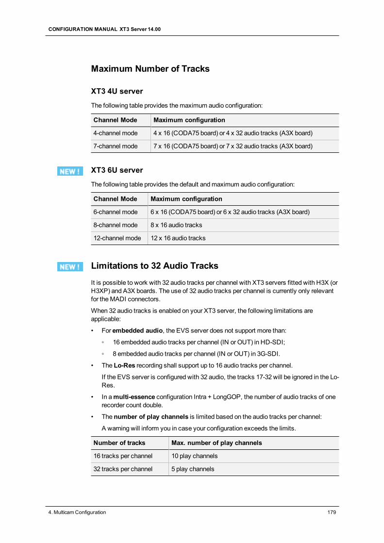
Maximum Number of Tracks
XT3 4U server
The following table provides themaximum audio configuration:
Channel Mode Maximum configuration
4-channel mode 4 x 16 (CODA75 board) or 4 x 32 audio tracks (A3X board)
7-channel mode 7 x 16 (CODA75 board) or 7 x 32 audio tracks (A3X board)
XT3 6U server
The following table provides the default andmaximum audio configuration:
Channel Mode Maximum configuration
6-channel mode 6 x 16 (CODA75 board) or 6 x 32 audio tracks (A3X board)
8-channel mode 8 x 16 audio tracks
12-channel mode 12 x 16 audio tracks
Limitations to 32 Audio Tracks
It is possible to work with 32 audio tracks per channel with XT3 servers fitted with H3X (orH3XP) and A3X boards. The use of 32 audio tracks per channel is currently only relevantfor theMADI connectors.
When 32 audio tracks is enabled on your XT3 server, the following limitations areapplicable:
• For embedded audio, the EVS server does not support more than:
◦ 16 embedded audio tracks per channel (IN or OUT) in HD-SDI;
◦ 8 embedded audio tracks per channel (IN or OUT) in 3G-SDI.
• The Lo-Res recording shall support up to 16 audio tracks per channel.
If the EVS server is configured with 32 audio, the tracks 17-32 will be ignored in the Lo-Res.
• In amulti-essence configuration Intra + LongGOP, the number of audio tracks of onerecorder count double.
• The number of play channels is limited based on the audio tracks per channel:
A warning will inform you in case your configuration exceeds the limits.
Number of tracks Max. number of play channels
16 tracks per channel 10 play channels
32 tracks per channel 5 play channels
CONFIGURATION MANUAL XT3 Server 14.00
4. MulticamConfiguration 179
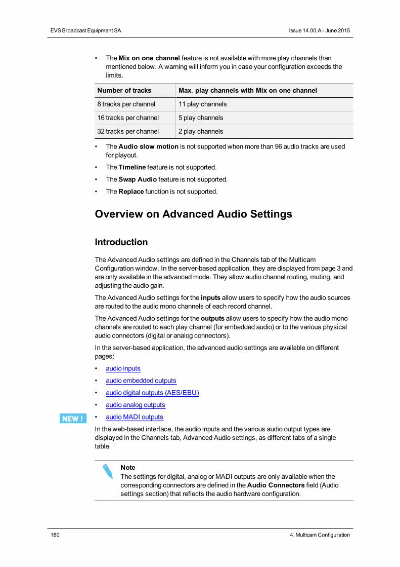
• TheMix on one channel feature is not available with more play channels thanmentioned below. A warning will inform you in case your configuration exceeds thelimits.
Number of tracks Max. play channels with Mix on one channel
8 tracks per channel 11 play channels
16 tracks per channel 5 play channels
32 tracks per channel 2 play channels
• TheAudio slow motion is not supported whenmore than 96 audio tracks are usedfor playout.
• The Timeline feature is not supported.
• TheSwap Audio feature is not supported.
• TheReplace function is not supported.
Overview on Advanced Audio Settings
Introduction
The Advanced Audio settings are defined in the Channels tab of theMulticamConfiguration window. In the server-based application, they are displayed from page 3 andare only available in the advancedmode. They allow audio channel routing, muting, andadjusting the audio gain.
The Advanced Audio settings for the inputs allow users to specify how the audio sourcesare routed to the audiomono channels of each record channel.
The Advanced Audio settings for the outputs allow users to specify how the audiomonochannels are routed to each play channel (for embedded audio) or to the various physicalaudio connectors (digital or analog connectors).
In the server-based application, the advanced audio settings are available on differentpages:
• audio inputs
• audio embedded outputs
• audio digital outputs (AES/EBU)
• audio analog outputs
• audioMADI outputs
In the web-based interface, the audio inputs and the various audio output types aredisplayed in the Channels tab, Advanced Audio settings, as different tabs of a singletable.
NoteThe settings for digital, analog or MADI outputs are only available when thecorresponding connectors are defined in theAudio Connectors field (Audiosettings section) that reflects the audio hardware configuration.
180 4. MulticamConfiguration
EVSBroadcast Equipment SA Issue 14.00.A - June 2015
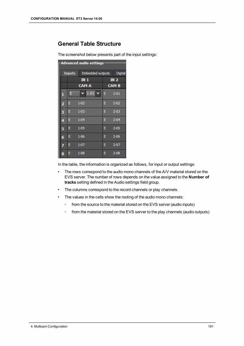
General Table Structure
The screenshot below presents part of the input settings:
In the table, the information is organized as follows, for input or output settings:
• The rows correspond to the audiomono channels of the A/V material stored on theEVS server. The number of rows depends on the value assigned to theNumber oftracks setting defined in the Audio settings field group.
• The columns correspond to the record channels or play channels.
• The values in the cells show the rooting of the audiomono channels:
◦ from the source to thematerial stored on the EVS server (audio inputs)
◦ from thematerial stored on the EVS server to the play channels (audio outputs)
CONFIGURATION MANUAL XT3 Server 14.00
4. MulticamConfiguration 181
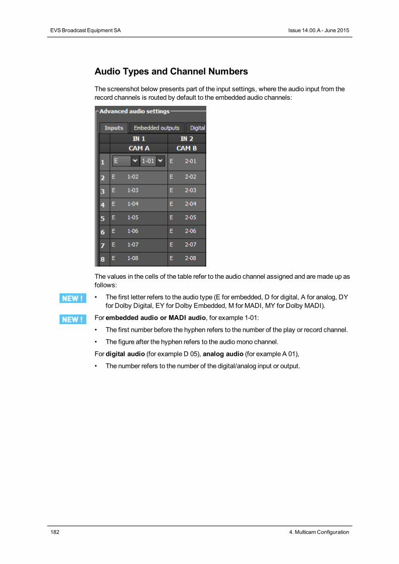
Audio Types and Channel Numbers
The screenshot below presents part of the input settings, where the audio input from therecord channels is routed by default to the embedded audio channels:
The values in the cells of the table refer to the audio channel assigned and aremade up asfollows:
• The first letter refers to the audio type (E for embedded, D for digital, A for analog, DYfor Dolby Digital, EY for Dolby Embedded, M for MADI, MY for Dolby MADI).
For embedded audio or MADI audio, for example 1-01:
• The first number before the hyphen refers to the number of the play or record channel.
• The figure after the hyphen refers to the audiomono channel.
For digital audio (for example D 05), analog audio (for example A 01),
• The number refers to the number of the digital/analog input or output.
182 4. MulticamConfiguration
EVSBroadcast Equipment SA Issue 14.00.A - June 2015
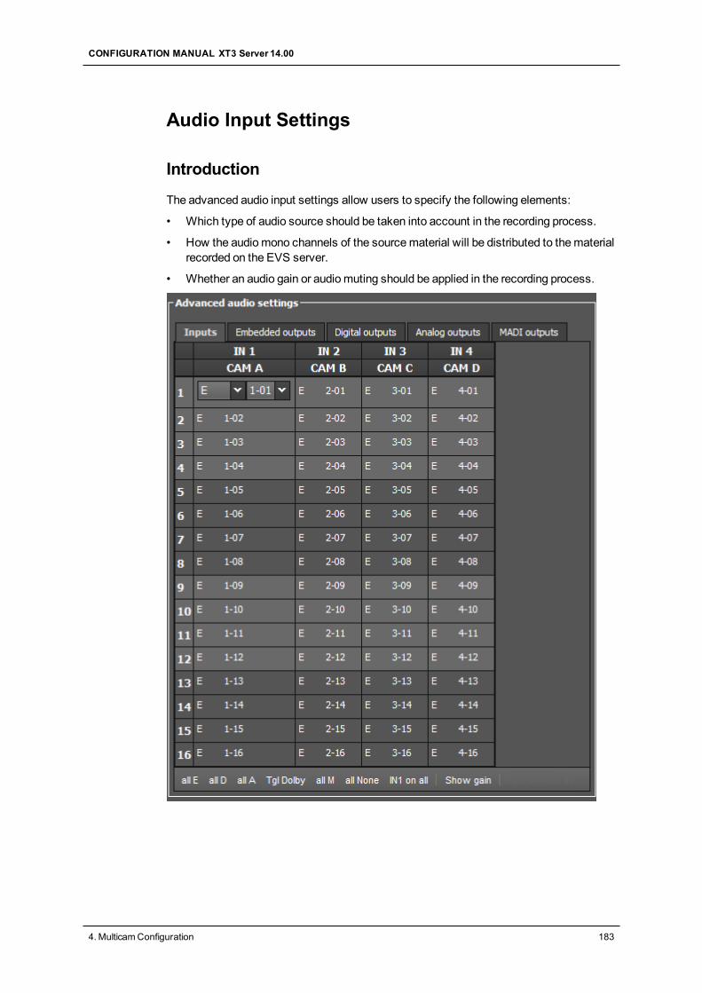
Audio Input Settings
Introduction
The advanced audio input settings allow users to specify the following elements:
• Which type of audio source should be taken into account in the recording process.
• How the audiomono channels of the sourcematerial will be distributed to thematerialrecorded on the EVS server.
• Whether an audio gain or audiomuting should be applied in the recording process.
CONFIGURATION MANUAL XT3 Server 14.00
4. MulticamConfiguration 183
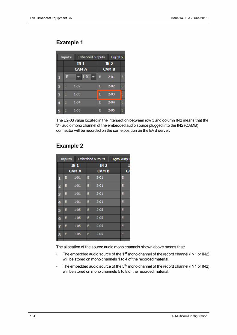
Example 1
The E2-03 value located in the intersection between row 3 and column IN2means that the3rd audiomono channel of the embedded audio source plugged into the IN2 (CAMB)connector will be recorded on the same position on the EVS server.
Example 2
The allocation of the source audiomono channels shown abovemeans that:
• The embedded audio source of the 1stmono channel of the record channel (IN1 or IN2)will be stored onmono channels 1 to 4 of the recordedmaterial.
• The embedded audio source of the 5thmono channel of the record channel (IN1 or IN2)will be stored onmono channels 5 to 8 of the recordedmaterial.
184 4. MulticamConfiguration
EVSBroadcast Equipment SA Issue 14.00.A - June 2015
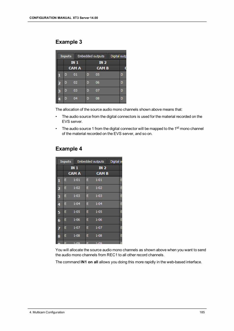
Example 3
The allocation of the source audiomono channels shown abovemeans that:
• The audio source from the digital connectors is used for thematerial recorded on theEVS server.
• The audio source 1 from the digital connector will bemapped to the 1stmono channelof thematerial recorded on the EVS server, and so on.
Example 4
Youwill allocate the source audiomono channels as shown above when you want to sendthe audiomono channels from REC1 to all other record channels.
The command IN1 on all allows you doing this more rapidly in the web-based interface.
CONFIGURATION MANUAL XT3 Server 14.00
4. MulticamConfiguration 185
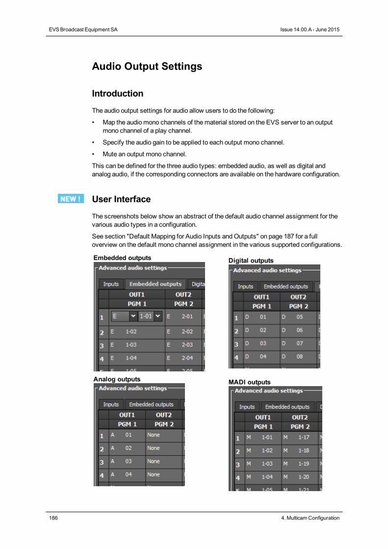
Audio Output Settings
Introduction
The audio output settings for audio allow users to do the following:
• Map the audiomono channels of thematerial stored on the EVS server to an outputmono channel of a play channel.
• Specify the audio gain to be applied to each output mono channel.
• Mute an output mono channel.
This can be defined for the three audio types: embedded audio, as well as digital andanalog audio, if the corresponding connectors are available on the hardware configuration.
User Interface
The screenshots below show an abstract of the default audio channel assignment for thevarious audio types in a configuration.
See section "Default Mapping for Audio Inputs andOutputs" on page 187 for a fulloverview on the default mono channel assignment in the various supported configurations.
Embedded outputs Digital outputs
Analog outputs MADI outputs
186 4. MulticamConfiguration
EVSBroadcast Equipment SA Issue 14.00.A - June 2015
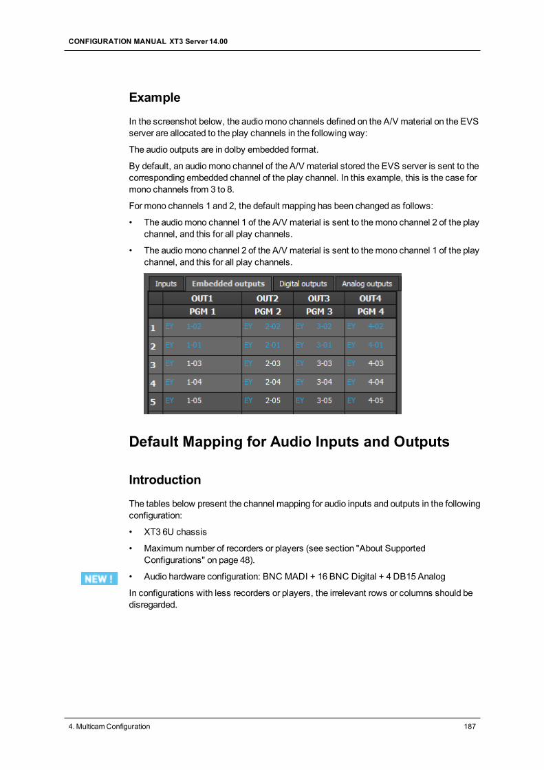
Example
In the screenshot below, the audiomono channels defined on the A/V material on the EVSserver are allocated to the play channels in the following way:
The audio outputs are in dolby embedded format.
By default, an audiomono channel of the A/V material stored the EVS server is sent to thecorresponding embedded channel of the play channel. In this example, this is the case formono channels from 3 to 8.
For mono channels 1 and 2, the default mapping has been changed as follows:
• The audiomono channel 1 of the A/V material is sent to themono channel 2 of the playchannel, and this for all play channels.
• The audiomono channel 2 of the A/V material is sent to themono channel 1 of the playchannel, and this for all play channels.
Default Mapping for Audio Inputs and Outputs
Introduction
The tables below present the channel mapping for audio inputs and outputs in the followingconfiguration:
• XT3 6U chassis
• Maximum number of recorders or players (see section "About SupportedConfigurations" on page 48).
• Audio hardware configuration: BNC MADI + 16 BNC Digital + 4 DB15 Analog
In configurations with less recorders or players, the irrelevant rows or columns should bedisregarded.
CONFIGURATION MANUAL XT3 Server 14.00
4. MulticamConfiguration 187
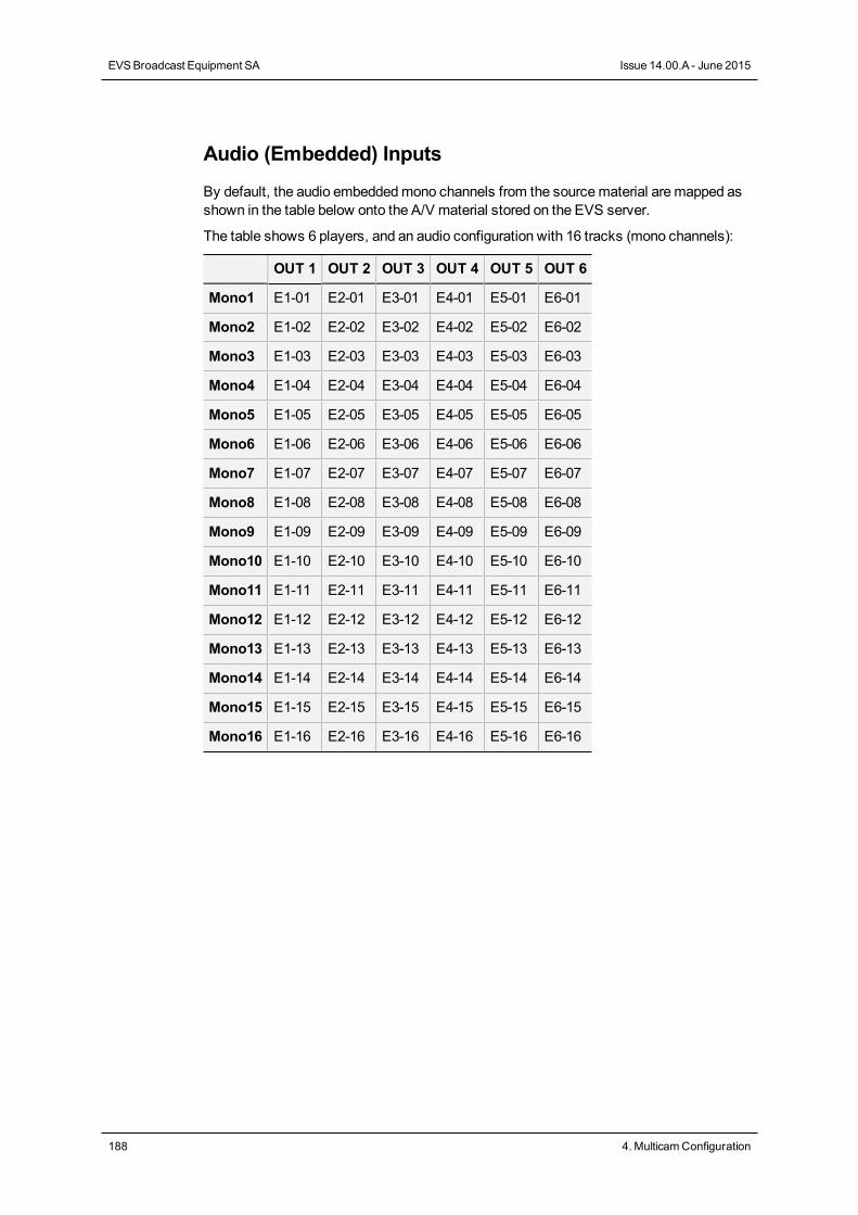
Audio (Embedded) Inputs
By default, the audio embeddedmono channels from the sourcematerial aremapped asshown in the table below onto the A/V material stored on the EVS server.
The table shows 6 players, and an audio configuration with 16 tracks (mono channels):
OUT 1 OUT 2 OUT 3 OUT 4 OUT 5 OUT 6
Mono1 E1-01 E2-01 E3-01 E4-01 E5-01 E6-01
Mono2 E1-02 E2-02 E3-02 E4-02 E5-02 E6-02
Mono3 E1-03 E2-03 E3-03 E4-03 E5-03 E6-03
Mono4 E1-04 E2-04 E3-04 E4-04 E5-04 E6-04
Mono5 E1-05 E2-05 E3-05 E4-05 E5-05 E6-05
Mono6 E1-06 E2-06 E3-06 E4-06 E5-06 E6-06
Mono7 E1-07 E2-07 E3-07 E4-07 E5-07 E6-07
Mono8 E1-08 E2-08 E3-08 E4-08 E5-08 E6-08
Mono9 E1-09 E2-09 E3-09 E4-09 E5-09 E6-09
Mono10 E1-10 E2-10 E3-10 E4-10 E5-10 E6-10
Mono11 E1-11 E2-11 E3-11 E4-11 E5-11 E6-11
Mono12 E1-12 E2-12 E3-12 E4-12 E5-12 E6-12
Mono13 E1-13 E2-13 E3-13 E4-13 E5-13 E6-13
Mono14 E1-14 E2-14 E3-14 E4-14 E5-14 E6-14
Mono15 E1-15 E2-15 E3-15 E4-15 E5-15 E6-15
Mono16 E1-16 E2-16 E3-16 E4-16 E5-16 E6-16
188 4. MulticamConfiguration
EVSBroadcast Equipment SA Issue 14.00.A - June 2015
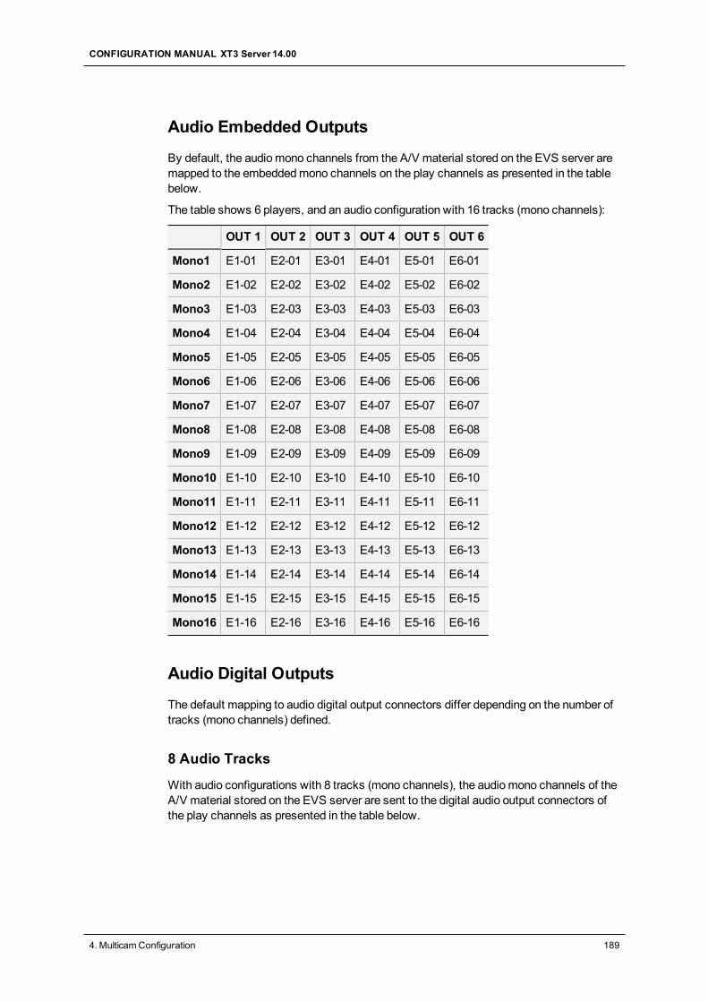
Audio Embedded Outputs
By default, the audiomono channels from the A/V material stored on the EVS server aremapped to the embeddedmono channels on the play channels as presented in the tablebelow.
The table shows 6 players, and an audio configuration with 16 tracks (mono channels):
OUT 1 OUT 2 OUT 3 OUT 4 OUT 5 OUT 6
Mono1 E1-01 E2-01 E3-01 E4-01 E5-01 E6-01
Mono2 E1-02 E2-02 E3-02 E4-02 E5-02 E6-02
Mono3 E1-03 E2-03 E3-03 E4-03 E5-03 E6-03
Mono4 E1-04 E2-04 E3-04 E4-04 E5-04 E6-04
Mono5 E1-05 E2-05 E3-05 E4-05 E5-05 E6-05
Mono6 E1-06 E2-06 E3-06 E4-06 E5-06 E6-06
Mono7 E1-07 E2-07 E3-07 E4-07 E5-07 E6-07
Mono8 E1-08 E2-08 E3-08 E4-08 E5-08 E6-08
Mono9 E1-09 E2-09 E3-09 E4-09 E5-09 E6-09
Mono10 E1-10 E2-10 E3-10 E4-10 E5-10 E6-10
Mono11 E1-11 E2-11 E3-11 E4-11 E5-11 E6-11
Mono12 E1-12 E2-12 E3-12 E4-12 E5-12 E6-12
Mono13 E1-13 E2-13 E3-13 E4-13 E5-13 E6-13
Mono14 E1-14 E2-14 E3-14 E4-14 E5-14 E6-14
Mono15 E1-15 E2-15 E3-15 E4-15 E5-15 E6-15
Mono16 E1-16 E2-16 E3-16 E4-16 E5-16 E6-16
Audio Digital Outputs
The default mapping to audio digital output connectors differ depending on the number oftracks (mono channels) defined.
8 Audio Tracks
With audio configurations with 8 tracks (mono channels), the audiomono channels of theA/V material stored on the EVS server are sent to the digital audio output connectors ofthe play channels as presented in the table below.
CONFIGURATION MANUAL XT3 Server 14.00
4. MulticamConfiguration 189
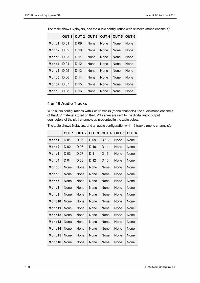
The table shows 6 players, and the audio configuration with 8 tracks (mono channels):
OUT 1 OUT 2 OUT 3 OUT 4 OUT 5 OUT 6
Mono1 D 01 D 09 None None None None
Mono2 D 02 D 10 None None None None
Mono3 D 03 D 11 None None None None
Mono4 D 04 D 12 None None None None
Mono5 D 05 D 13 None None None None
Mono6 D 06 D 14 None None None None
Mono7 D 07 D 15 None None None None
Mono8 D 08 D 16 None None None None
4 or 16 Audio Tracks
With audio configurations with 4 or 16 tracks (mono channels), the audiomono channelsof the A/V material stored on the EVS server are sent to the digital audio outputconnectors of the play channels as presented in the table below.
The table shows 6 players, and an audio configuration with 16 tracks (mono channels):
OUT 1 OUT 2 OUT 3 OUT 4 OUT 5 OUT 6
Mono1 D 01 D 05 D 09 D 13 None None
Mono2 D 02 D 06 D 10 D 14 None None
Mono3 D 03 D 07 D 11 D 15 None None
Mono4 D 04 D 08 D 12 D 16 None None
Mono5 None None None None None None
Mono6 None None None None None None
Mono7 None None None None None None
Mono8 None None None None None None
Mono9 None None None None None None
Mono10 None None None None None None
Mono11 None None None None None None
Mono12 None None None None None None
Mono13 None None None None None None
Mono14 None None None None None None
Mono15 None None None None None None
Mono16 None None None None None None
190 4. MulticamConfiguration
EVSBroadcast Equipment SA Issue 14.00.A - June 2015
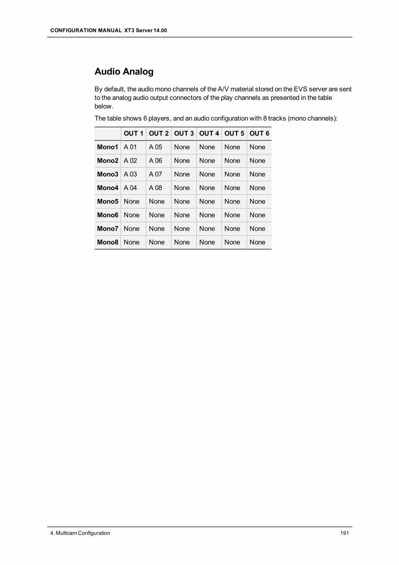
Audio Analog
By default, the audiomono channels of the A/V material stored on the EVS server are sentto the analog audio output connectors of the play channels as presented in the tablebelow.
The table shows 6 players, and an audio configuration with 8 tracks (mono channels):
OUT 1 OUT 2 OUT 3 OUT 4 OUT 5 OUT 6
Mono1 A 01 A 05 None None None None
Mono2 A 02 A 06 None None None None
Mono3 A 03 A 07 None None None None
Mono4 A 04 A 08 None None None None
Mono5 None None None None None None
Mono6 None None None None None None
Mono7 None None None None None None
Mono8 None None None None None None
CONFIGURATION MANUAL XT3 Server 14.00
4. MulticamConfiguration 191
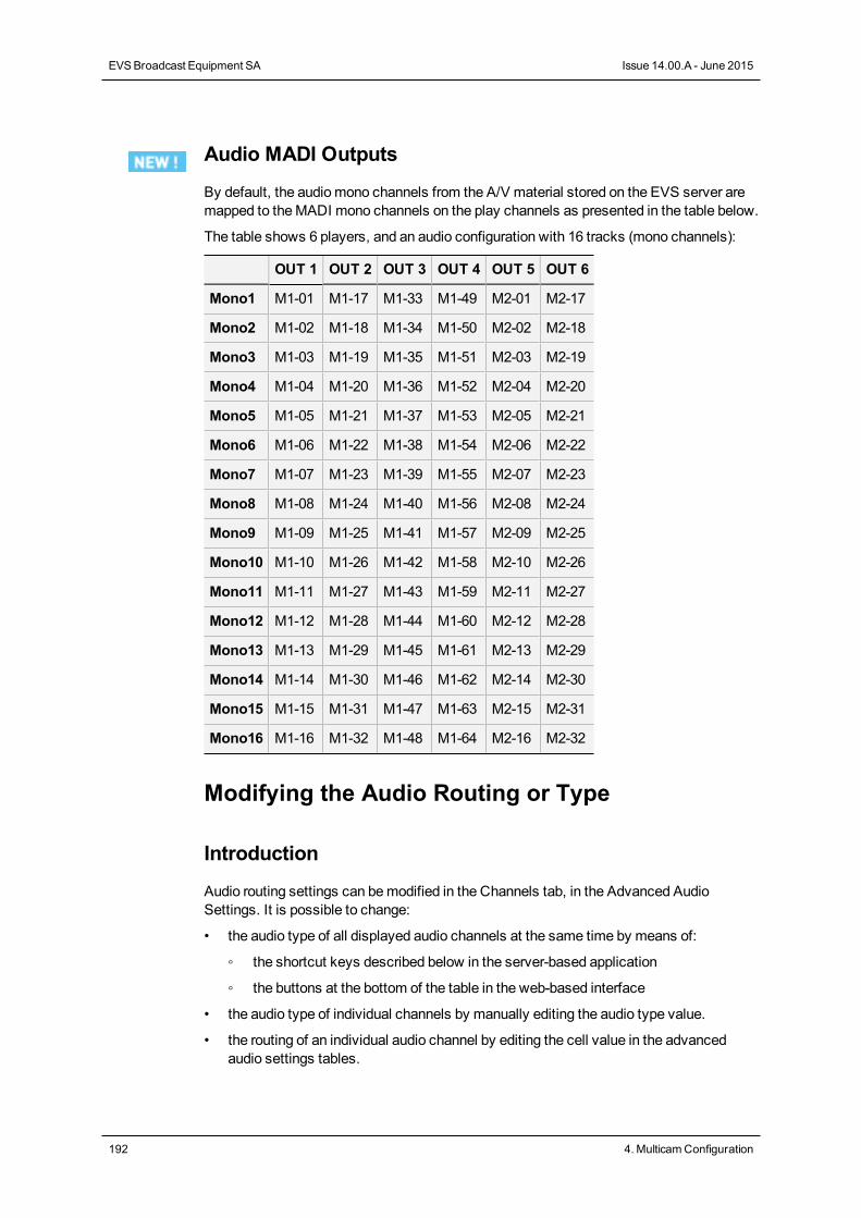
Audio MADI Outputs
By default, the audiomono channels from the A/V material stored on the EVS server aremapped to theMADI mono channels on the play channels as presented in the table below.
The table shows 6 players, and an audio configuration with 16 tracks (mono channels):
OUT 1 OUT 2 OUT 3 OUT 4 OUT 5 OUT 6
Mono1 M1-01 M1-17 M1-33 M1-49 M2-01 M2-17
Mono2 M1-02 M1-18 M1-34 M1-50 M2-02 M2-18
Mono3 M1-03 M1-19 M1-35 M1-51 M2-03 M2-19
Mono4 M1-04 M1-20 M1-36 M1-52 M2-04 M2-20
Mono5 M1-05 M1-21 M1-37 M1-53 M2-05 M2-21
Mono6 M1-06 M1-22 M1-38 M1-54 M2-06 M2-22
Mono7 M1-07 M1-23 M1-39 M1-55 M2-07 M2-23
Mono8 M1-08 M1-24 M1-40 M1-56 M2-08 M2-24
Mono9 M1-09 M1-25 M1-41 M1-57 M2-09 M2-25
Mono10 M1-10 M1-26 M1-42 M1-58 M2-10 M2-26
Mono11 M1-11 M1-27 M1-43 M1-59 M2-11 M2-27
Mono12 M1-12 M1-28 M1-44 M1-60 M2-12 M2-28
Mono13 M1-13 M1-29 M1-45 M1-61 M2-13 M2-29
Mono14 M1-14 M1-30 M1-46 M1-62 M2-14 M2-30
Mono15 M1-15 M1-31 M1-47 M1-63 M2-15 M2-31
Mono16 M1-16 M1-32 M1-48 M1-64 M2-16 M2-32
Modifying the Audio Routing or Type
Introduction
Audio routing settings can bemodified in the Channels tab, in the Advanced AudioSettings. It is possible to change:
• the audio type of all displayed audio channels at the same time by means of:
◦ the shortcut keys described below in the server-based application
◦ the buttons at the bottom of the table in the web-based interface
• the audio type of individual channels by manually editing the audio type value.
• the routing of an individual audio channel by editing the cell value in the advancedaudio settings tables.
192 4. MulticamConfiguration
EVSBroadcast Equipment SA Issue 14.00.A - June 2015
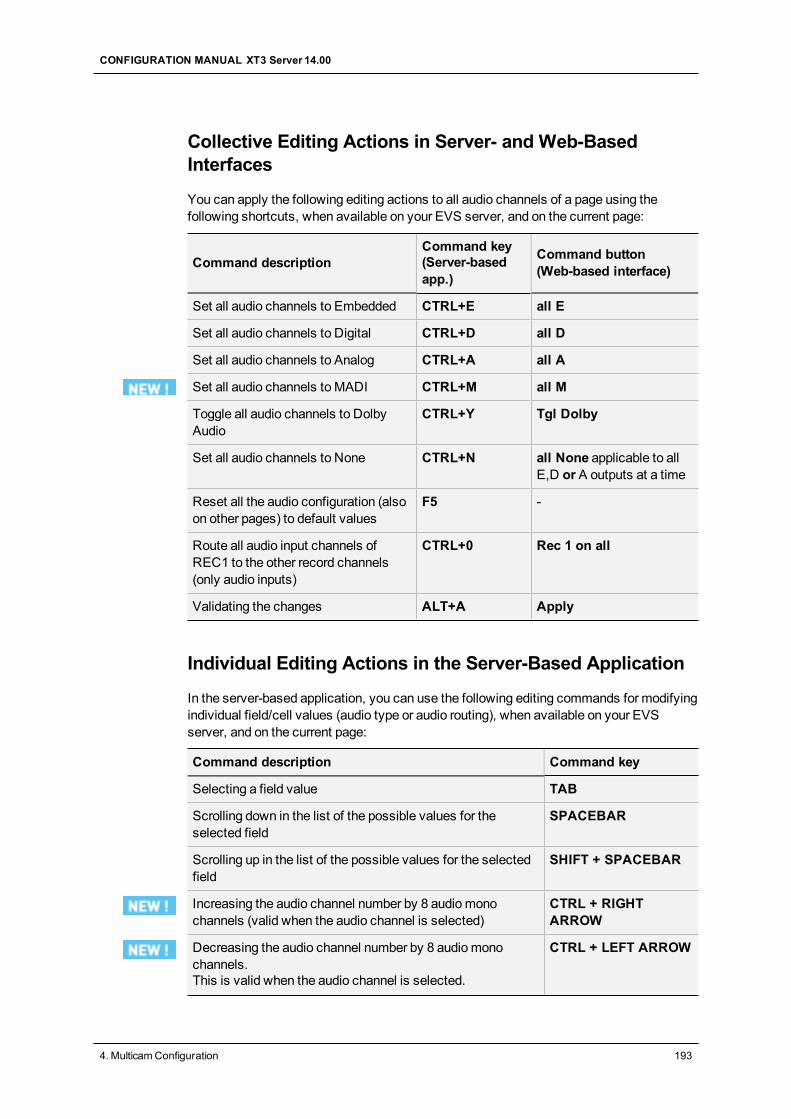
Collective Editing Actions in Server- and Web-BasedInterfaces
You can apply the following editing actions to all audio channels of a page using thefollowing shortcuts, when available on your EVS server, and on the current page:
Command descriptionCommand key(Server-basedapp.)
Command button(Web-based interface)
Set all audio channels to Embedded CTRL+E all E
Set all audio channels to Digital CTRL+D all D
Set all audio channels to Analog CTRL+A all A
Set all audio channels to MADI CTRL+M all M
Toggle all audio channels to DolbyAudio
CTRL+Y Tgl Dolby
Set all audio channels to None CTRL+N all None applicable to allE,D or A outputs at a time
Reset all the audio configuration (alsoon other pages) to default values
F5 -
Route all audio input channels ofREC1 to the other record channels(only audio inputs)
CTRL+0 Rec 1 on all
Validating the changes ALT+A Apply
Individual Editing Actions in the Server-Based Application
In the server-based application, you can use the following editing commands for modifyingindividual field/cell values (audio type or audio routing), when available on your EVSserver, and on the current page:
Command description Command key
Selecting a field value TAB
Scrolling down in the list of the possible values for theselected field
SPACEBAR
Scrolling up in the list of the possible values for the selectedfield
SHIFT + SPACEBAR
Increasing the audio channel number by 8 audiomonochannels (valid when the audio channel is selected)
CTRL + RIGHTARROW
Decreasing the audio channel number by 8 audiomonochannels.This is valid when the audio channel is selected.
CTRL + LEFT ARROW
CONFIGURATION MANUAL XT3 Server 14.00
4. MulticamConfiguration 193
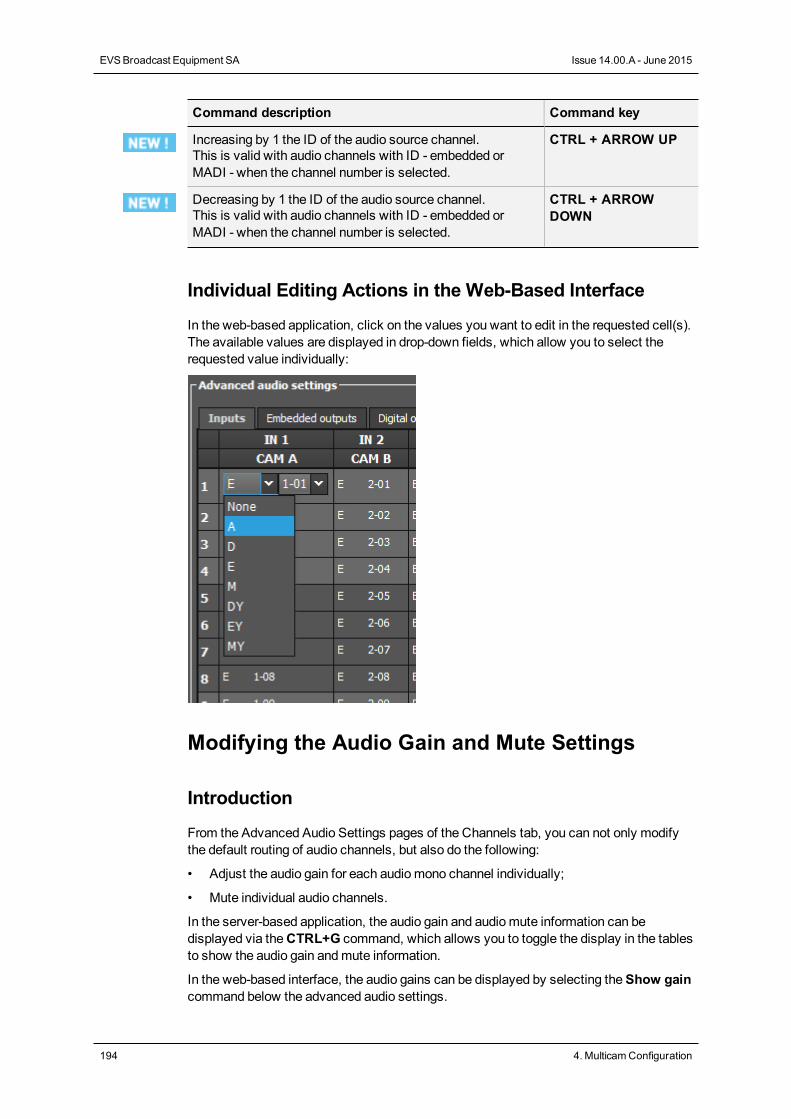
Command description Command key
Increasing by 1 the ID of the audio source channel.This is valid with audio channels with ID - embedded orMADI - when the channel number is selected.
CTRL + ARROW UP
Decreasing by 1 the ID of the audio source channel.This is valid with audio channels with ID - embedded orMADI - when the channel number is selected.
CTRL + ARROWDOWN
Individual Editing Actions in the Web-Based Interface
In the web-based application, click on the values you want to edit in the requested cell(s).The available values are displayed in drop-down fields, which allow you to select therequested value individually:
Modifying the Audio Gain and Mute Settings
Introduction
From the Advanced Audio Settings pages of the Channels tab, you can not only modifythe default routing of audio channels, but also do the following:
• Adjust the audio gain for each audiomono channel individually;
• Mute individual audio channels.
In the server-based application, the audio gain and audiomute information can bedisplayed via theCTRL+G command, which allows you to toggle the display in the tablesto show the audio gain andmute information.
In the web-based interface, the audio gains can be displayed by selecting theShow gaincommand below the advanced audio settings.
194 4. MulticamConfiguration
EVSBroadcast Equipment SA Issue 14.00.A - June 2015
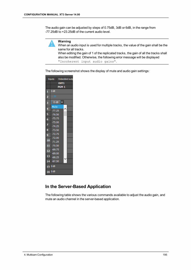
The audio gain can be adjusted by steps of 0.75dB, 3dB or 6dB, in the range from-77.25dB to +23.25dB of the current audio level.
WarningWhen an audio input is used for multiple tracks, the value of the gain shall be thesame for all tracks.When editing the gain of 1 of the replicated tracks, the gain of all the tracks shallalso bemodified. Otherwise, the following error message will be displayed"Incoherent input audio gains".
The following screenshot shows the display of mute and audio gain settings:
In the Server-Based Application
The following table shows the various commands available to adjust the audio gain, andmute an audio channel in the server-based application.
CONFIGURATION MANUAL XT3 Server 14.00
4. MulticamConfiguration 195
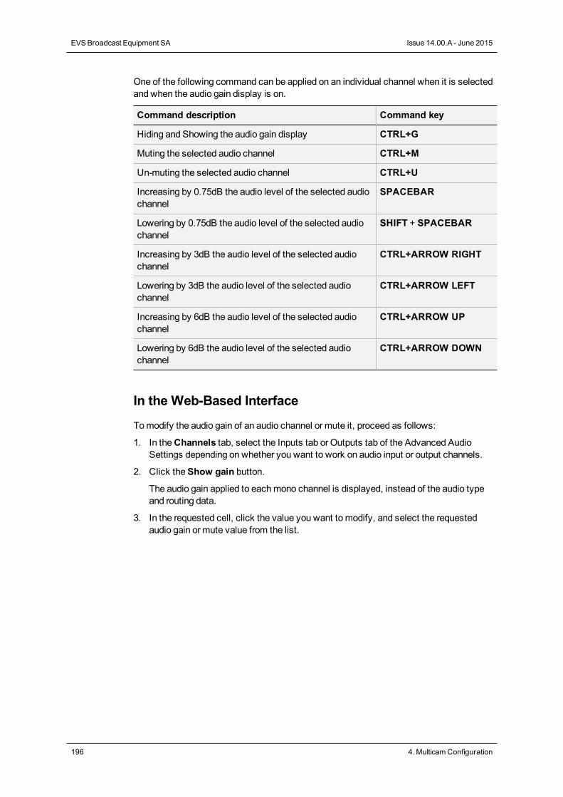
One of the following command can be applied on an individual channel when it is selectedand when the audio gain display is on.
Command description Command key
Hiding and Showing the audio gain display CTRL+G
Muting the selected audio channel CTRL+M
Un-muting the selected audio channel CTRL+U
Increasing by 0.75dB the audio level of the selected audiochannel
SPACEBAR
Lowering by 0.75dB the audio level of the selected audiochannel
SHIFT + SPACEBAR
Increasing by 3dB the audio level of the selected audiochannel
CTRL+ARROW RIGHT
Lowering by 3dB the audio level of the selected audiochannel
CTRL+ARROW LEFT
Increasing by 6dB the audio level of the selected audiochannel
CTRL+ARROW UP
Lowering by 6dB the audio level of the selected audiochannel
CTRL+ARROW DOWN
In the Web-Based Interface
Tomodify the audio gain of an audio channel or mute it, proceed as follows:
1. In theChannels tab, select the Inputs tab or Outputs tab of the Advanced AudioSettings depending on whether you want to work on audio input or output channels.
2. Click theShow gain button.
The audio gain applied to eachmono channel is displayed, instead of the audio typeand routing data.
3. In the requested cell, click the value you want to modify, and select the requestedaudio gain or mute value from the list.
196 4. MulticamConfiguration
EVSBroadcast Equipment SA Issue 14.00.A - June 2015
Dolby Audio Management
Concepts
• Dolby Digital or Dolby 5.1 or AC-3, is an audio coding system containing up to 6discrete channels of sound, with 5 channels for normal-range speakers (20 Hz -20,000 Hz) (Right front, Center, Left Front, Right Rear and Left Rear) and one channel(20 Hz - 120 Hz) for the LFE, or subwoofer.
• Dolby E is a professional coding system optimized for the distribution of surround andmultichannel audio through two-channel postproduction and broadcastinginfrastructures, or for recording surround audio on two audio tracks of conventionaldigital video tapes, video servers, communication links, switchers, and routers.
NoteDolby E is not supported in Proxy essence. If audio channels are configured inDolby E in amulti-essence configuration with Proxy, the Proxy output will haveno associated audio.
Available Dolby Configurations
Case 1: The 5.1 audio signal is carried on 6 discrete PCM audiochannels
• It is available on an XT3 server in all configurations.
• The audio can be analog, digital or embedded depending on the configuration.
• In AES audio, if the audio is correctly genlocked to the video, the sample rateconverter can be switched off.
Case 2: The 5.1 audio signal is coded in the two-channel Dolby Estandard
• Dolby E over AES/EBU links
◦ Set the configuration of the pair of channels carrying the Dolby E signal to “DY” intheMulticam Configuration window, Channels tab. This has two effects :
• It disables the sample rate converter on the input channels.
• It forces all transitions to a hard cut.
CONFIGURATION MANUAL XT3 Server 14.00
4. MulticamConfiguration 197
If the sample rate converter is activated and the audio configuration is amix betweenPCM audio over AES and Dolby E over AES, the sample rate converter will only beapplied to the PCM over AES signal.
• Dolby E Embedded in the SDI/HD SDI stream
◦ Set the configuration of the pair of channels carrying the Dolby E signal to “EY” intheMulticam Configuration window, Channels tab. This will force the transition toa hard cut.
◦ The sample rate converter parameter does not apply to embedded audio.
The Dolby E transitions will be correct as long as:
• the configuration is correct
• the AES stream containing Dolby E is correctly synchronized with the video
Dolby E transitions will not be correct (2 frames of mute at the transitions) if the audio typeis set to E instead of EY or D instead of DY.
Audio effects (scrub, slow motion) are not possible in Dolby E. If they are used anyway,the audio will bemuted.
4.3.4. Timecode and Data Insertion
Timecode Settings
User Interface
The Timecode settings allow specifying which type of timecode the users want to use asthe reference to work on a given recorder of an EVS server.
The selection of a timecode type, using the timecode settings, rely on themanagement oftwo timecode jump tables.
These fields are available in the following interfaces:
• in theMulticam Configuration window, Channels tab, in the advanced display mode onthe server- and web-based interfaces;
• partly in the Technical menu of the Remote Control Panel (T2.X)
198 4. MulticamConfiguration
EVSBroadcast Equipment SA Issue 14.00.A - June 2015
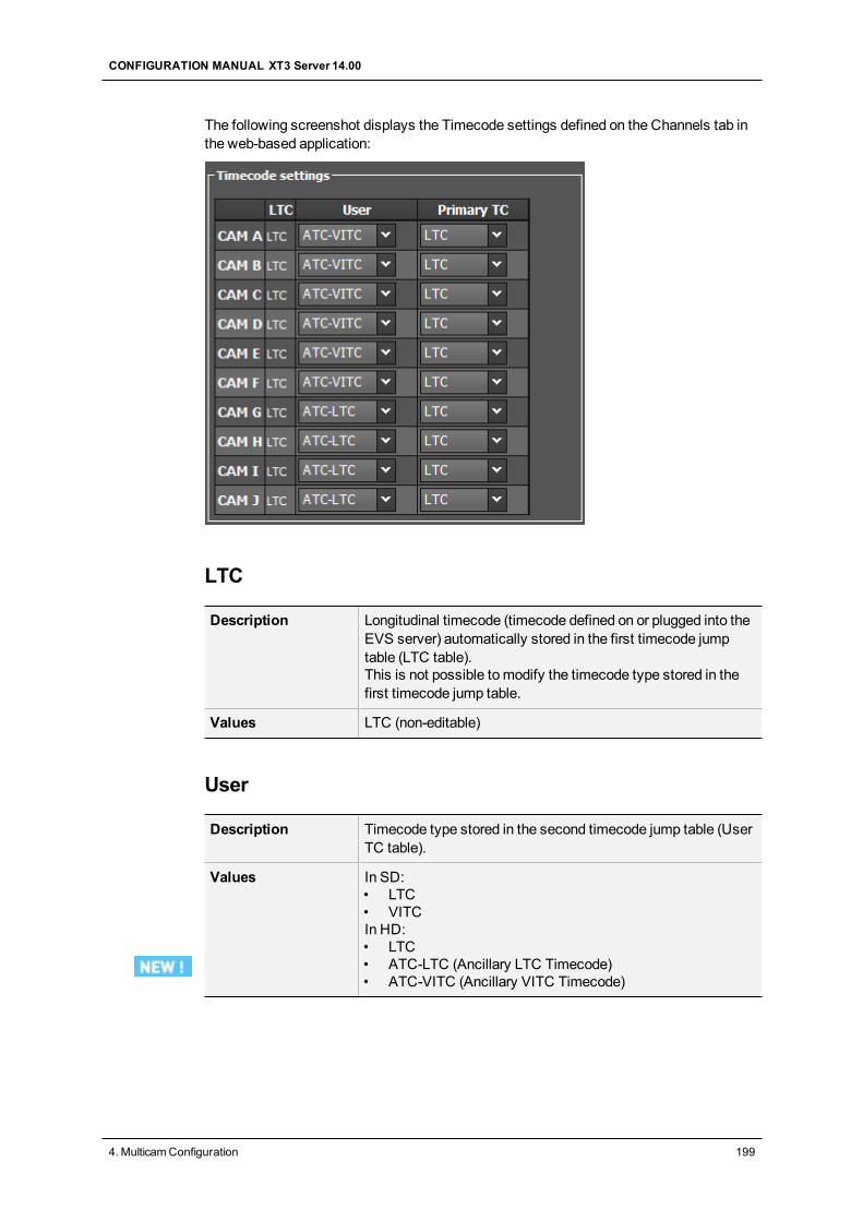
The following screenshot displays the Timecode settings defined on the Channels tab inthe web-based application:
LTC
Description Longitudinal timecode (timecode defined on or plugged into theEVS server) automatically stored in the first timecode jumptable (LTC table).This is not possible to modify the timecode type stored in thefirst timecode jump table.
Values LTC (non-editable)
User
Description Timecode type stored in the second timecode jump table (UserTC table).
Values In SD:• LTC• VITCIn HD:• LTC• ATC-LTC (Ancillary LTC Timecode)• ATC-VITC (Ancillary VITC Timecode)
CONFIGURATION MANUAL XT3 Server 14.00
4. MulticamConfiguration 199
Primary TC
Description Timecode type that is displayed at the bottom the VGA and isused to work with the videomaterial stored on the givenrecorder.Usually, an LTC timecode is used to perform operations on liveevents. A VITC timecode is used for videomaterial ingestedfrom tapes as it is the timecode embedded in the video signal.
Values • LTC: LTC timecode, which is automatically stored in theLTC table. It is specified in the LTC field.
• User:User-defined timecode, which is stored in the USERTC table and specified in theUser field.
OSD Display Depending on the value selected for this setting, the timecodedisplayed at the bottom of the user’s OSD will have a differentcolor:• If the LTC timecode is selected, the timecode color will be
white.• If the USER timecode is selected, the timecode color will
be yellow.
Timecode Insertion Settings
User Interface
The Timecode Insertion settings allow themanagement of VITC or ancillary timecodeschannel by channel.
These fields are available in the following interfaces:
• in theMulticam Configuration window, Channels tab, in the advanced display mode onthe server- and web-based interfaces.
200 4. MulticamConfiguration
EVSBroadcast Equipment SA Issue 14.00.A - June 2015
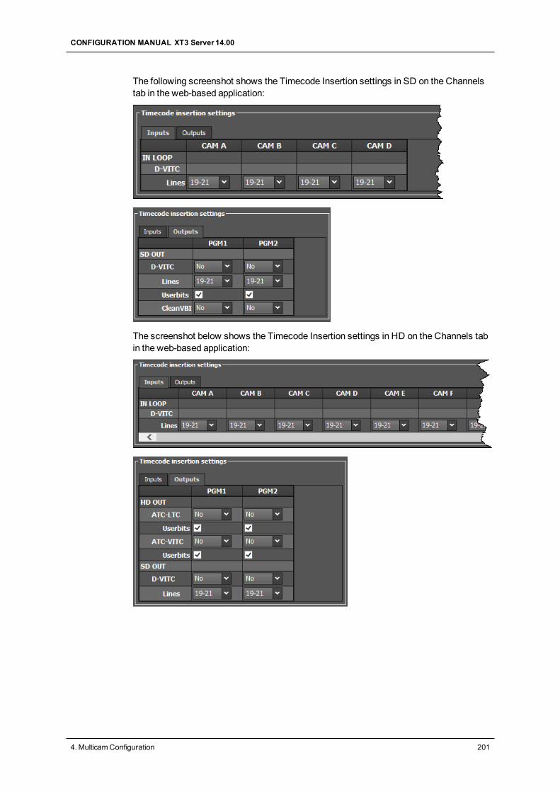
The following screenshot shows the Timecode Insertion settings in SD on the Channelstab in the web-based application:
The screenshot below shows the Timecode Insertion settings in HD on the Channels tabin the web-based application:
CONFIGURATION MANUAL XT3 Server 14.00
4. MulticamConfiguration 201
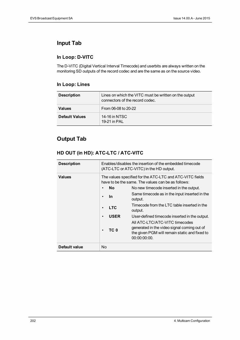
Input Tab
In Loop: D-VITC
The D-VITC (Digital Vertical Interval Timecode) and userbits are always written on themonitoring SD outputs of the record codec and are the same as on the source video.
In Loop: Lines
Description Lines on which the VITC must be written on the outputconnectors of the record codec.
Values From 06-08 to 20-22
Default Values 14-16 in NTSC19-21 in PAL
Output Tab
HD OUT (in HD): ATC-LTC / ATC-VITC
Description Enables/disables the insertion of the embedded timecode(ATC-LTC or ATC-VITC) in the HD output.
Values The values specified for the ATC-LTC and ATC-VITC fieldshave to be the same. The values can be as follows:• No No new timecode inserted in the output.
• In Same timecode as in the input inserted in theoutput.
• LTC Timecode from the LTC table inserted in theoutput.
• USER User-defined timecode inserted in the output.
• TC 0
All ATC-LTC/ATC-VITC timecodesgenerated in the video signal coming out ofthe given PGMwill remain static and fixed to00:00:00:00.
Default value No
202 4. MulticamConfiguration
EVSBroadcast Equipment SA Issue 14.00.A - June 2015
HD OUT (in HD): UserBits
Description Enables/disables the insertion of the user bits in the HD output.The values specified for the ATC-LTC and ATC-VITC fieldshave to be the same.When TC0 is selected in the ATC-LTC and ATC-VITC field,the user bits values will also remain static and fixed to00:00:00:00 whatever the selected value.
Values Yes (default) / No
SD OUT (in HD/SD): D-VITC
Description Enables/disables the insertion of the embedded timecode (D-VITC) in the SD output.
Values The values specified for the D-VITC field can be as follows:• No No new timecode inserted in the output.
• In Same timecode as in the input inserted in theoutput.
• LTC Timecode from the LTC table inserted in theoutput.
• USER User-defined timecode inserted in the output.
• TC 0All D-VITC timecodes generated in the videosignal coming out of the given PGMwillremain static and fixed to 00:00:00:00.
Default value No
SD OUT (in HD/SD): Lines
Description Lines on which the specified timecodemust be written on theloop of the input.
Values From 06-08 to 20-22
Default values • 14-16 in NTSC• 19-21 in PAL
SD OUT (in SD only): UserBits
Description Enables/disables the insertion of the user bits in the SD output.When TC0 is selected for the D-VITC field, the user bitsvalues will also remain static and fixed to 00:00:00:00whatever the selected value.
Values Yes (default) / No
CONFIGURATION MANUAL XT3 Server 14.00
4. MulticamConfiguration 203
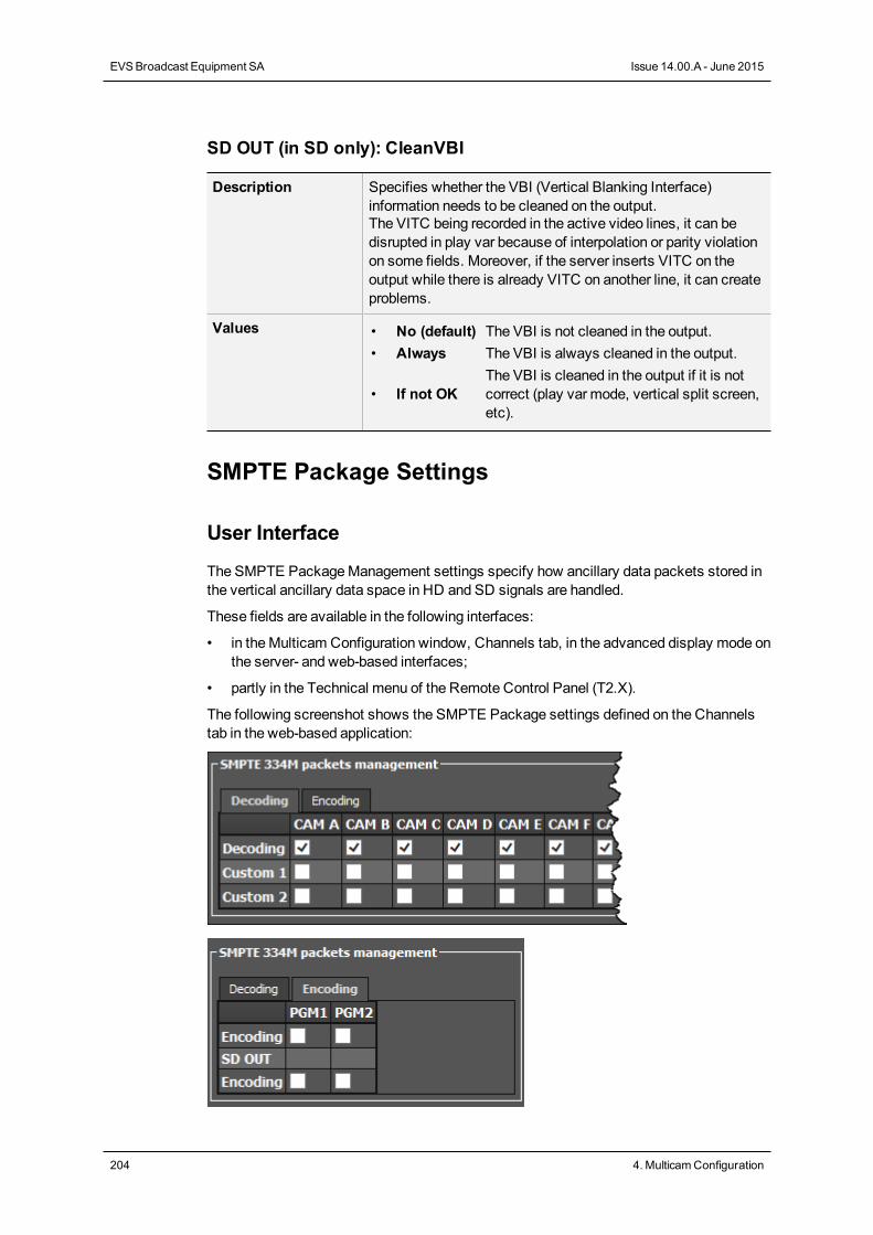
SD OUT (in SD only): CleanVBI
Description Specifies whether the VBI (Vertical Blanking Interface)information needs to be cleaned on the output.The VITC being recorded in the active video lines, it can bedisrupted in play var because of interpolation or parity violationon some fields. Moreover, if the server inserts VITC on theoutput while there is already VITC on another line, it can createproblems.
Values • No (default) The VBI is not cleaned in the output.• Always The VBI is always cleaned in the output.
• If not OKThe VBI is cleaned in the output if it is notcorrect (play var mode, vertical split screen,etc).
SMPTE Package Settings
User Interface
The SMPTE PackageManagement settings specify how ancillary data packets stored inthe vertical ancillary data space in HD and SD signals are handled.
These fields are available in the following interfaces:
• in theMulticam Configuration window, Channels tab, in the advanced display mode onthe server- and web-based interfaces;
• partly in the Technical menu of the Remote Control Panel (T2.X).
The following screenshot shows the SMPTE Package settings defined on the Channelstab in the web-based application:
204 4. MulticamConfiguration
EVSBroadcast Equipment SA Issue 14.00.A - June 2015
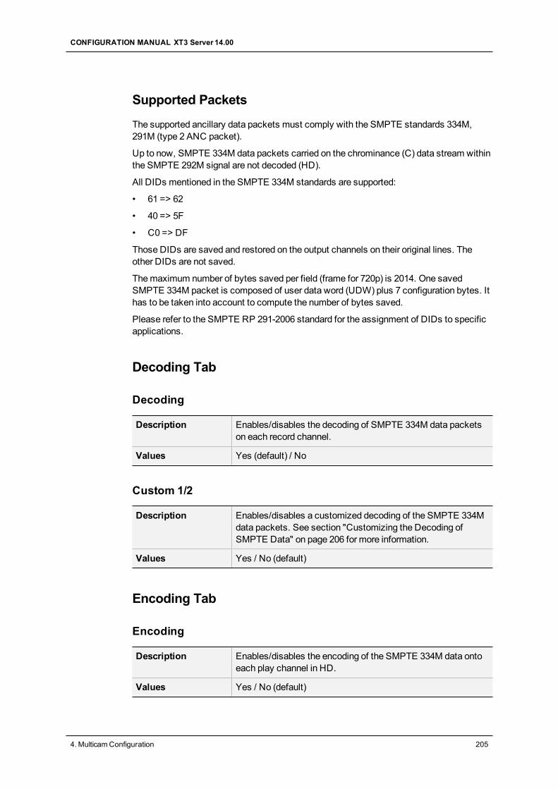
Supported Packets
The supported ancillary data packets must comply with the SMPTE standards 334M,291M (type 2 ANC packet).
Up to now, SMPTE 334M data packets carried on the chrominance (C) data stream withinthe SMPTE 292M signal are not decoded (HD).
All DIDs mentioned in the SMPTE 334M standards are supported:
• 61 => 62
• 40 => 5F
• C0 => DF
Those DIDs are saved and restored on the output channels on their original lines. Theother DIDs are not saved.
Themaximum number of bytes saved per field (frame for 720p) is 2014. One savedSMPTE 334M packet is composed of user data word (UDW) plus 7 configuration bytes. Ithas to be taken into account to compute the number of bytes saved.
Please refer to the SMPTE RP 291-2006 standard for the assignment of DIDs to specificapplications.
Decoding Tab
Decoding
Description Enables/disables the decoding of SMPTE 334M data packetson each record channel.
Values Yes (default) / No
Custom 1/2
Description Enables/disables a customized decoding of the SMPTE 334Mdata packets. See section "Customizing the Decoding ofSMPTE Data" on page 206 for more information.
Values Yes / No (default)
Encoding Tab
Encoding
Description Enables/disables the encoding of the SMPTE 334M data ontoeach play channel in HD.
Values Yes / No (default)
CONFIGURATION MANUAL XT3 Server 14.00
4. MulticamConfiguration 205
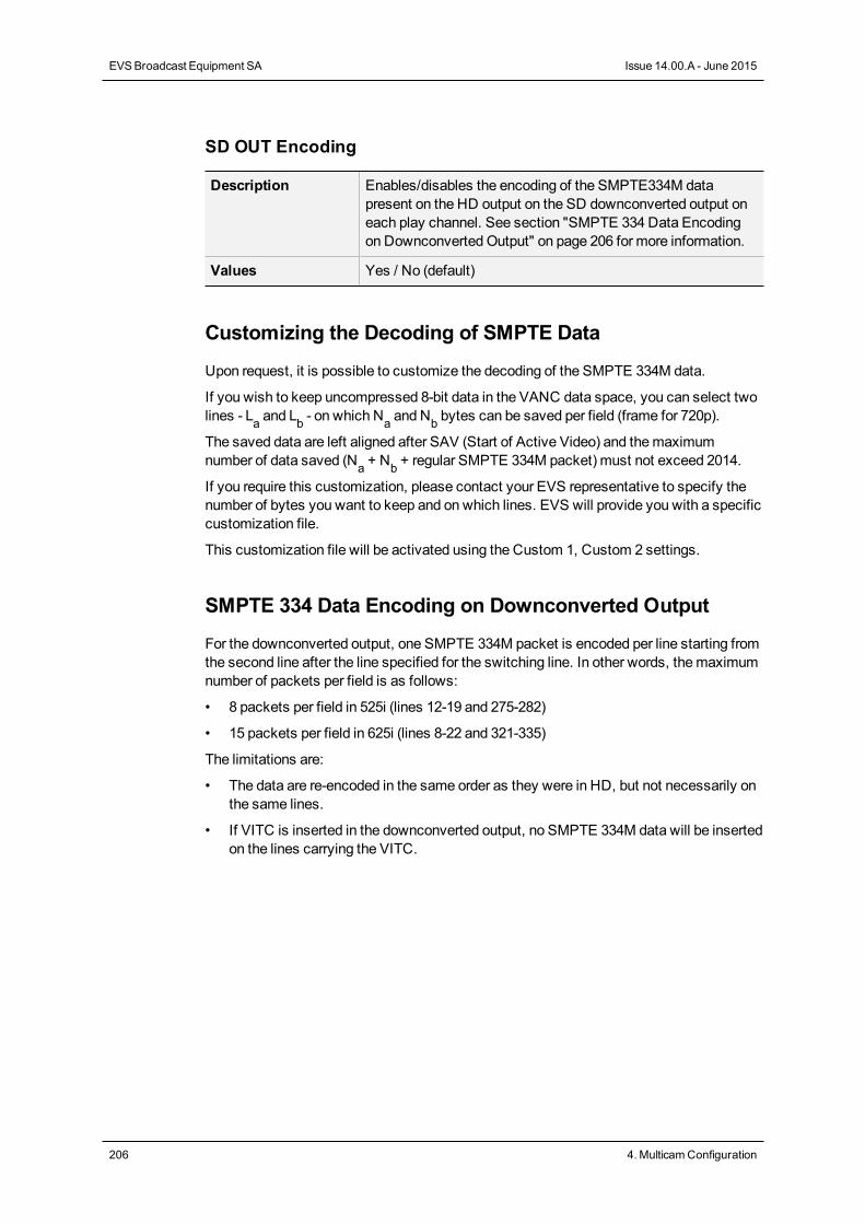
SD OUT Encoding
Description Enables/disables the encoding of the SMPTE334M datapresent on the HD output on the SD downconverted output oneach play channel. See section "SMPTE 334 Data Encodingon Downconverted Output" on page 206 for more information.
Values Yes / No (default)
Customizing the Decoding of SMPTE Data
Upon request, it is possible to customize the decoding of the SMPTE 334M data.
If you wish to keep uncompressed 8-bit data in the VANC data space, you can select twolines - La and Lb - on which Na and Nb bytes can be saved per field (frame for 720p).
The saved data are left aligned after SAV (Start of Active Video) and themaximumnumber of data saved (Na + Nb + regular SMPTE 334M packet) must not exceed 2014.
If you require this customization, please contact your EVS representative to specify thenumber of bytes you want to keep and on which lines. EVS will provide you with a specificcustomization file.
This customization file will be activated using the Custom 1, Custom 2 settings.
SMPTE 334 Data Encoding on Downconverted Output
For the downconverted output, one SMPTE 334M packet is encoded per line starting fromthe second line after the line specified for the switching line. In other words, themaximumnumber of packets per field is as follows:
• 8 packets per field in 525i (lines 12-19 and 275-282)
• 15 packets per field in 625i (lines 8-22 and 321-335)
The limitations are:
• The data are re-encoded in the same order as they were in HD, but not necessarily onthe same lines.
• If VITC is inserted in the downconverted output, no SMPTE 334M data will be insertedon the lines carrying the VITC.
206 4. MulticamConfiguration
EVSBroadcast Equipment SA Issue 14.00.A - June 2015
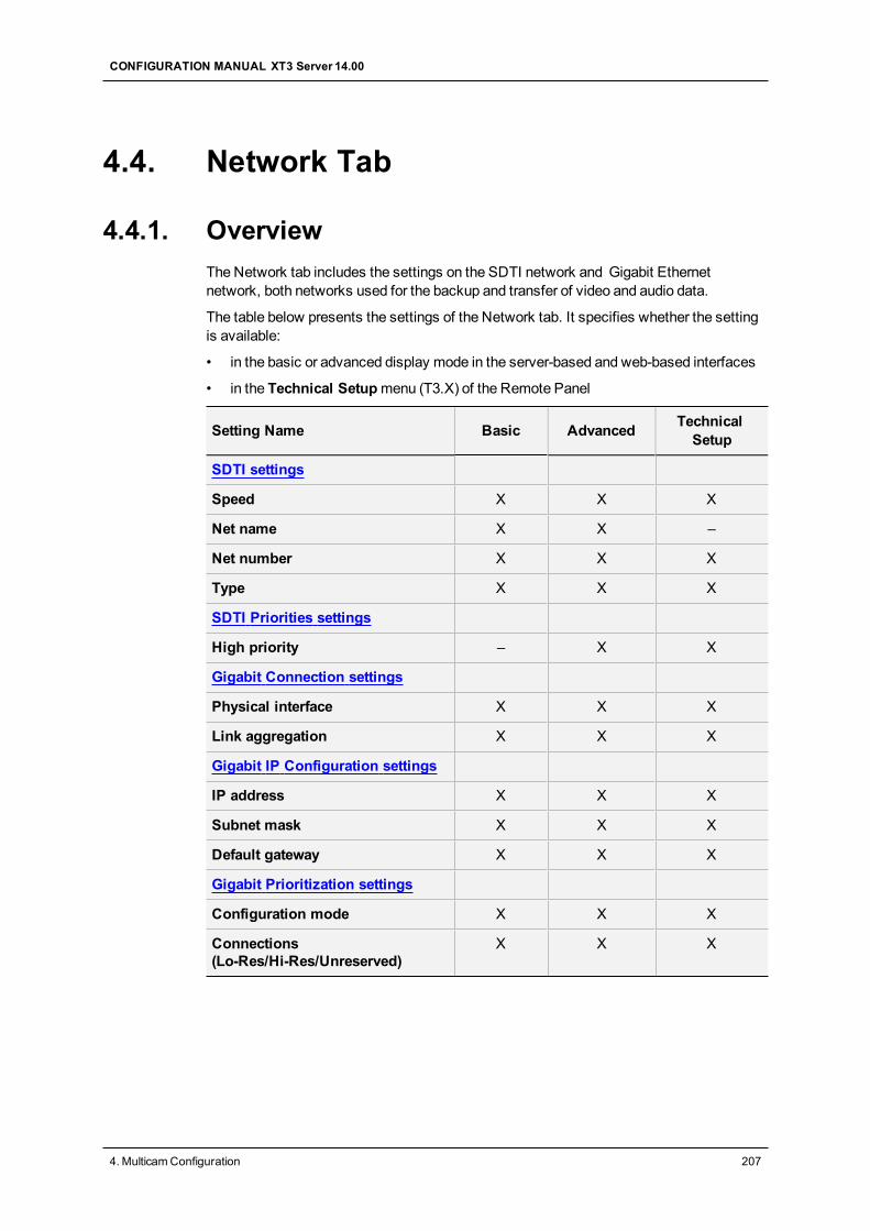
4.4. Network Tab
4.4.1. OverviewThe Network tab includes the settings on the SDTI network and Gigabit Ethernetnetwork, both networks used for the backup and transfer of video and audio data.
The table below presents the settings of the Network tab. It specifies whether the settingis available:
• in the basic or advanced display mode in the server-based and web-based interfaces
• in the Technical Setupmenu (T3.X) of the Remote Panel
Setting Name Basic Advanced TechnicalSetup
SDTI settings
Speed X X X
Net name X X –
Net number X X X
Type X X X
SDTI Priorities settings
High priority – X X
Gigabit Connection settings
Physical interface X X X
Link aggregation X X X
Gigabit IP Configuration settings
IP address X X X
Subnet mask X X X
Default gateway X X X
Gigabit Prioritization settings
Configuration mode X X X
Connections(Lo-Res/Hi-Res/Unreserved)
X X X
CONFIGURATION MANUAL XT3 Server 14.00
4. MulticamConfiguration 207
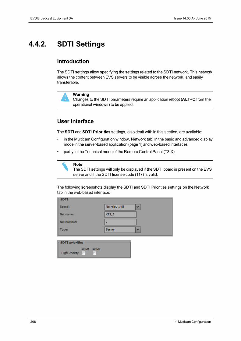
4.4.2. SDTI Settings
Introduction
The SDTI settings allow specifying the settings related to the SDTI network. This networkallows the content between EVS servers to be visible across the network, and easilytransferable.
WarningChanges to the SDTI parameters require an application reboot (ALT+Q from theoperational windows) to be applied.
User Interface
TheSDTI andSDTI Priorities settings, also dealt with in this section, are available:
• in theMulticam Configuration window, Network tab, in the basic and advanced displaymode in the server-based application (page 1) and web-based interfaces
• partly in the Technical menu of the Remote Control Panel (T3.X)
NoteThe SDTI settings will only be displayed if the SDTI board is present on the EVSserver and if the SDTI license code (117) is valid.
The following screenshots display the SDTI and SDTI Priorities settings on the Networktab in the web-based interface:
208 4. MulticamConfiguration
EVSBroadcast Equipment SA Issue 14.00.A - June 2015
Speed
Description Enables the selection of the SDTI option and the bandwidth forthe XNet network.On the XT3 server, there is one pair of SDTI connectors: XNet2Non-Relay connectors are used at 1485 or 2970Mbps.The SDTI circuit is closed only when theMulticam software isstarted.
Values The following values are available:• No Relay 1485 (Mbps)• No Relay 2970 (Mbps)• Off
Default value Off
WarningAll EVS servers in an SDTI network must be set up with the same SDTI speed.If the SDTI speed is changed on an EVS server, it will automatically bedisconnected from the XNet network, without prior warning.
Net Name
Description Machine name on the SDTI network.It is not mandatory because a network number is assigned tothe EVS server. It is however recommended as it helps toeasily identify the servers connected to the XNet network.The Net Namewill be displayed even if the SDTI code is notvalid.
Values The Net Name is user-defined and cannot exceed 8 characters.
Default value By default, no Net Name is assigned.
Net Number
Description The Net Number parameter defines themachine number on thenetwork. This number is user-defined andmust be unique foreach system on the network. An error message appears if thenumber is already assigned to another machine.
Values Range between 1 and 29
Default value 1
CONFIGURATION MANUAL XT3 Server 14.00
4. MulticamConfiguration 209
Type
Description Defines the privileges of the EVS server on the SDTI network.
Values The following values are possible:• Client: It cannot access the content on other EVS servers.• Master: It can access all content on other EVS servers.• Server: It manages the SDTI network, and it can access all
content on other EVS servers.Only one EVS server on the network should be set toServer type. If no Server type is defined on the network,XNet will not be established. If more than one EVS serveris defined as Server type, only the first one to connect willbe the actual Server.
Whatever the server type defined, the content of an EVS servercan be accessed without restrictions by the other EVS servers(with typeMaster or Server) on the SDTI network.
Default value Server
High Priority
Description Defines a higher priority for a play channel of the local serverwhenever they play network clips/trains. This higher priority willonly apply in play, not in shuttle mode.
Values Yes / No (default)
NoteUsing this commandwill not prevent a freeze on the SDTI network if thenetwork is completely stalled. It is always worth checking the network statusand defining clear network usage rules if you wish to play footage across thenetwork.
4.4.3. Gigabit Connection
Introduction
TheGigabit connection allows the backup and transfer of the audio and video data withoutgoing through the SDTI network. TheGigabit Connection settings specify which interfaceprovides the gigabit connection on the EVS server.
210 4. MulticamConfiguration
EVSBroadcast Equipment SA Issue 14.00.A - June 2015
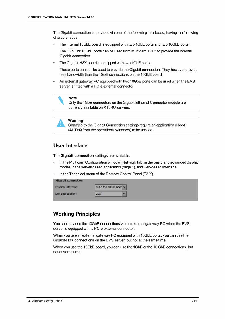
TheGigabit connection is provided via one of the following interfaces, having the followingcharacteristics:
• The internal 10GbE board is equipped with two 1GbE ports and two 10GbE ports.
The 1GbE or 10GbE ports can be used fromMulticam 12.05 to provide the internalGigabit connection.
• TheGigabit-H3X board is equipped with two 1GbE ports.
These ports can still be used to provide the Gigabit connection. They however provideless bandwidth than the 1GbE connections on the 10GbE board.
• An external gateway PC equipped with two 10GbE ports can be used when the EVSserver is fitted with a PCIe external connector.
NoteOnly the 1GbE connectors on the Gigabit Ethernet Connector module arecurrently available on XT3 4U servers.
WarningChanges to the Gigabit Connection settings require an application reboot(ALT+Q from the operational windows) to be applied.
User Interface
TheGigabit connection settings are available:
• in theMulticam Configuration window, Network tab, in the basic and advanced displaymodes in the server-based application (page 1), and web-based interface.
• in the Technical menu of the Remote Control Panel (T3.X).
Working Principles
You can only use the 10GbE connections via an external gateway PC when the EVSserver is equipped with a PCIe external connector.
When you use an external gateway PC equipped with 10GbE ports, you can use theGigabit-H3X connections on the EVS server, but not at the same time.
When you use the 10GbE board, you can use the 1GbE or the 10GbE connections, butnot at same time.
CONFIGURATION MANUAL XT3 Server 14.00
4. MulticamConfiguration 211
Teaming
Teaming is only available with the 10GbE board, on both its 1GbE or 10GbE interfaces.Teaming can be enabled using the Link Aggregation setting.
When teaming is active, and one of the GbE link fails, the other will seamlessly take overall ongoing and pending tasks.
Physical Interface
Availability This section is only available if the server is equipped with anGigabit-H3X board or a 10GbE board.
Description Specifies the physical interface that provides the GigabitEthernet connection.
Values The following values are available:• None
No gigabit interface is present.• Gigabit-H3X
One or two of the 1GbE connection of the Gigabit-H3Xboard is/are used.
• Gateway PCTheGigabit Ethernet connection is provided through theGigabit Gateway installed on a gateway PC, and the10GbE connector of the gateway PC is used. In this case,it is not possible to use the GbE connections available onthe EVS server.
• 1 GbE (on 10GbE board)One or two of the 1GbE connections on the 10GbE boardis/are used.
• 10 GbEOne or two of the 10GbE connections of the 10GbE boardis/are used.
Default Value The default value corresponds to themost efficient physicalinterface installed on the EVS server.
212 4. MulticamConfiguration
EVSBroadcast Equipment SA Issue 14.00.A - June 2015
Link aggregation
Description Specifies the teamingmethod when using the 1GbE or the10GbE ports of the 10GbE board.
Values The following values are available:• None
No link aggregationmethod is applied, and no teaming isprovided.
• LACPThe Link Aggregation Control Protocol is used to provideteaming.
• Adapter Fault ToleranceThe Adapter Fault Tolerance (AFT)method is used toprovide teaming.
• Switch Fault ToleranceThe Switch Fault Tolerance (SFT)method is used toprovide teaming.
Default Value None
4.4.4. Gigabit IP Configuration
Introduction
TheGigabit IP Configuration settings specify the IP addresses for the Gigabit connectionson theGigabit-H3X board or on the 10GbE board, depending on which GbE connectionsare specified in thePhysical Interface parameter in the Gigabit Connection settings.
WarningChanges to the Gigabit settings require an application reboot (ALT+Q from theoperational windows) to be applied.
User Interface
TheGigabit IP Configuration settings are available:
• in theMulticam Configuration window, Network tab, in the basic and advanced displaymodes in the server-based application (page 1), and web-based interface.
• in the Technical menu of the Remote Control Panel (T3.X).
The following screenshot displays the Gigabit IP Configuration settings on the Networktab in the web-based interface:
CONFIGURATION MANUAL XT3 Server 14.00
4. MulticamConfiguration 213
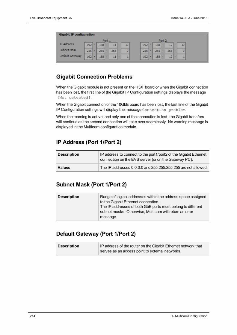
Gigabit Connection Problems
When theGigabit module is not present on the H3X board or when theGigabit connectionhas been lost, the first line of the Gigabit IP Configuration settings displays themessage!Not detected!.
When theGigabit connection of the 10GbE board has been lost, the last line of the GigabitIP Configuration settings will display themessage Connection problem.
When the teaming is active, and only one of the connection is lost, the Gigabit transferswill continue as the second connection will take over seamlessly. No warningmessage isdisplayed in theMulticam configurationmodule.
IP Address (Port 1/Port 2)
Description IP address to connect to the port1/port2 of the Gigabit Ethernetconnection on the EVS server (or on the Gateway PC).
Values The IP addresses 0.0.0.0 and 255.255.255.255 are not allowed.
Subnet Mask (Port 1/Port 2)
Description Range of logical addresses within the address space assignedto the Gigabit Ethernet connection.The IP addresses of both GbE ports must belong to differentsubnet masks. Otherwise, Multicam will return an errormessage.
Default Gateway (Port 1/Port 2)
Description IP address of the router on the Gigabit Ethernet network thatserves as an access point to external networks.
214 4. MulticamConfiguration
EVSBroadcast Equipment SA Issue 14.00.A - June 2015
4.4.5. Gigabit Prioritization Settings
Introduction
TheGigabit connection is used for several tasks (browsing, streaming, transfer, etc.). Forthis reason, prioritization parameters can be defined tomake sure the EVS server willhave a sufficient bandwidth to smoothly perform tasks seen as critical within a givenworkflow.
TheGigabit prioritization settings allow users to prioritize the transfer from/to the GigabitFTP server.
Warning• Changes to the Gigabit Prioritization settings require an application reboot
(ALT+Q from the operational windows) to be applied.• When the Truck Manager is used in a given workflow, it automatically
configures the Gigabit Prioritization settings to take into account theconnection needs of all EVS products in the workflow.
User Interface
TheGigabit Prioritization settings are available:
• in theMulticam Configuration window, Network tab, in the advanced display modeson page 2 in the server-based interface, and in the web-based interface.
The following screenshot highlights the Gigabit prioritization settings on the Network tab inthe web-based interface:
General Description
The prioritization settings consists in giving priority to a number of Lo-Res (Proxy)connections on theGigabit network.
Based on the effective bandwidth on the Gigabit interfaces of the EVS server, Multicamcalculates themaximum number of Lo-Res connections that can be granted with priority.
Knowing themaximum number of connections which can have priority, the administratorcan set the requested number of reserved connections for critical jobs (Lo-Res browsing,for example). The unreserved connections will be available for less prioritary jobs (backupof clips to be archived, for example).
CONFIGURATION MANUAL XT3 Server 14.00
4. MulticamConfiguration 215
When processing jobs, Multicam always makes use of the full available Gigabitbandwidth: If the bandwidth is not fully allocated, the remaining bandwidth is automaticallydistributed among the connections.
Configuration mode
Description Specifies whether and how you want to configure the prioritiesfor the Gigabit connections.
Values Two configurationmodes are available:• Disabled:
◦ The parameters for setting prioritization are hidden: youcannot reserve connections.
◦ The number of unreserved connections is automaticallyset to themaximum (25 connections).
• Enabled:◦ You can set the number of Lo-Res connections.◦ The number of unreserved connections is computed
and set automatically (never lower than 6).
Default value Disabled
Connections (Lo-Res)
Availability The setting is only available in Enabled configurationmode,and if the Lo-Res codec essence is active on the EVS server.
Description Allows configuring the number of Lo-Res connections allowedto the bandwidth of the EVS server.Each Lo-Res connection has a priority profile optimized for asmooth browsing of Lo-Res media, without impacting othertransfers.
Values The values is set in theReserved column.The number of remaining andmaximum Lo-Res connectionsfor the given server configuration is specified in theRemain./Max. column.
Default value 0
216 4. MulticamConfiguration
EVSBroadcast Equipment SA Issue 14.00.A - June 2015
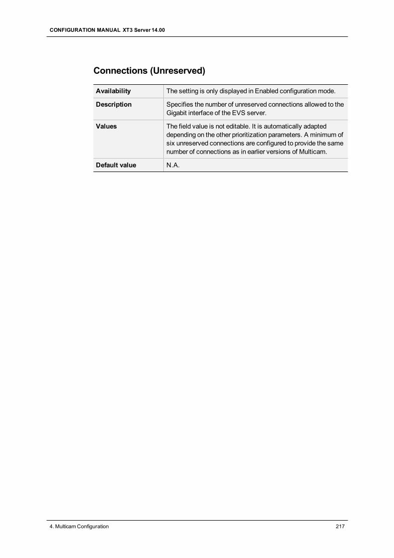
Connections (Unreserved)
Availability The setting is only displayed in Enabled configurationmode.
Description Specifies the number of unreserved connections allowed to theGigabit interface of the EVS server.
Values The field value is not editable. It is automatically adapteddepending on the other prioritization parameters. A minimum ofsix unreserved connections are configured to provide the samenumber of connections as in earlier versions of Multicam.
Default value N.A.
CONFIGURATION MANUAL XT3 Server 14.00
4. MulticamConfiguration 217
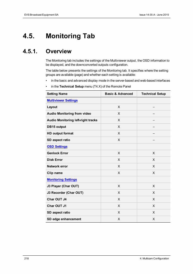
4.5. Monitoring Tab
4.5.1. OverviewTheMonitoring tab includes the settings of theMultiviewer output, the OSD information tobe displayed, and the downconverted outputs configuration.
The table below presents the settings of theMonitoring tab. It specifies where the settinggroups are available (page) and whether each setting is available:
• in the basic and advanced display mode in the server-based and web-based interfaces
• in the Technical Setupmenu (T4.X) of the Remote Panel
Setting Name Basic & Advanced Technical Setup
Multiviewer Settings
Layout X –
Audio Monitoring from video X –
Audio Monitoring left-right tracks X –
DB15 output X –
HD output format X –
SD aspect ratio X –
OSD Settings
Genlock Error X X
Disk Error X X
Network error X X
Clip name X X
Monitoring Settings
J3 Player (Char OUT) X X
J3 Recorder (Char OUT) X X
Char OUT J4 X X
Char OUT J1 X X
SD aspect ratio X X
SD edge enhancement X X
218 4. MulticamConfiguration
EVSBroadcast Equipment SA Issue 14.00.A - June 2015
4.5.2. Multiviewer Settings
Introduction
OnEVS servers equipped with V3X boards, the two ports available on the rear panelsallow the connection of two independent HD-SDI multiviewers.
This allows the following uses:
• two operators working independently on the same EVS server
• a single operator working with onemultiviewer displaying recorders, and a secondmultiviewer displaying players.
• one operator to have a recorder display of a 4K channel on onemultiviewer, and aplayer display of the 4K channel on the secondmultiviewer, for example.
TheMultiviewer settingsmake it possible to specify the settings for the twomultiviewers, such as the number of channels to combine and display, the audio andoutput video configuration.
NoteOnEVS servers with the latest rear panels, theMultiviewer connectors arelabeled OUT1 andOUT2.On EVS servers with former rear panels, the OUT1 connector is labeled HD-SDI, and the OUT2 is labeled SD-SDI.
User Interface
These fields are available in theMulticam Configuration window, Monitoring tab .
NoteTheMultiviewer settings will only be displayed if a Multiviewer board is presenton the EVS server.
The following screenshot displays theMultiviewer section on theMonitoring tab in theweb-based interface:
CONFIGURATION MANUAL XT3 Server 14.00
4. MulticamConfiguration 219
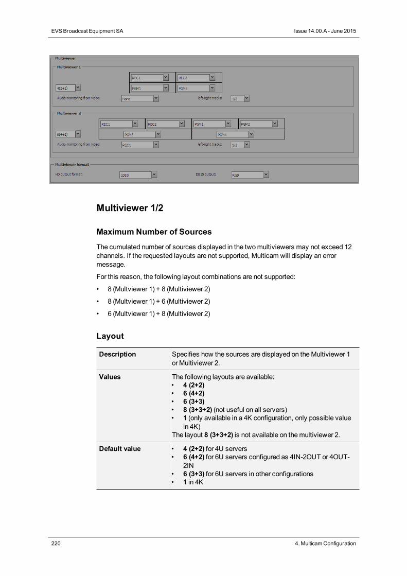
Multiviewer 1/2
Maximum Number of Sources
The cumulated number of sources displayed in the twomultiviewers may not exceed 12channels. If the requested layouts are not supported, Multicam will display an errormessage.
For this reason, the following layout combinations are not supported:
• 8 (Multviewer 1) + 8 (Multiviewer 2)
• 8 (Multviewer 1) + 6 (Multiviewer 2)
• 6 (Multviewer 1) + 8 (Multiviewer 2)
Layout
Description Specifies how the sources are displayed on theMultiviewer 1or Multiviewer 2.
Values The following layouts are available:• 4 (2+2)• 6 (4+2)• 6 (3+3)• 8 (3+3+2) (not useful on all servers)• 1 (only available in a 4K configuration, only possible value
in 4K)The layout 8 (3+3+2) is not available on themultiviewer 2.
Default value • 4 (2+2) for 4U servers• 6 (4+2) for 6U servers configured as 4IN-2OUT or 4OUT-
2IN• 6 (3+3) for 6U servers in other configurations• 1 in 4K
220 4. MulticamConfiguration
EVSBroadcast Equipment SA Issue 14.00.A - June 2015
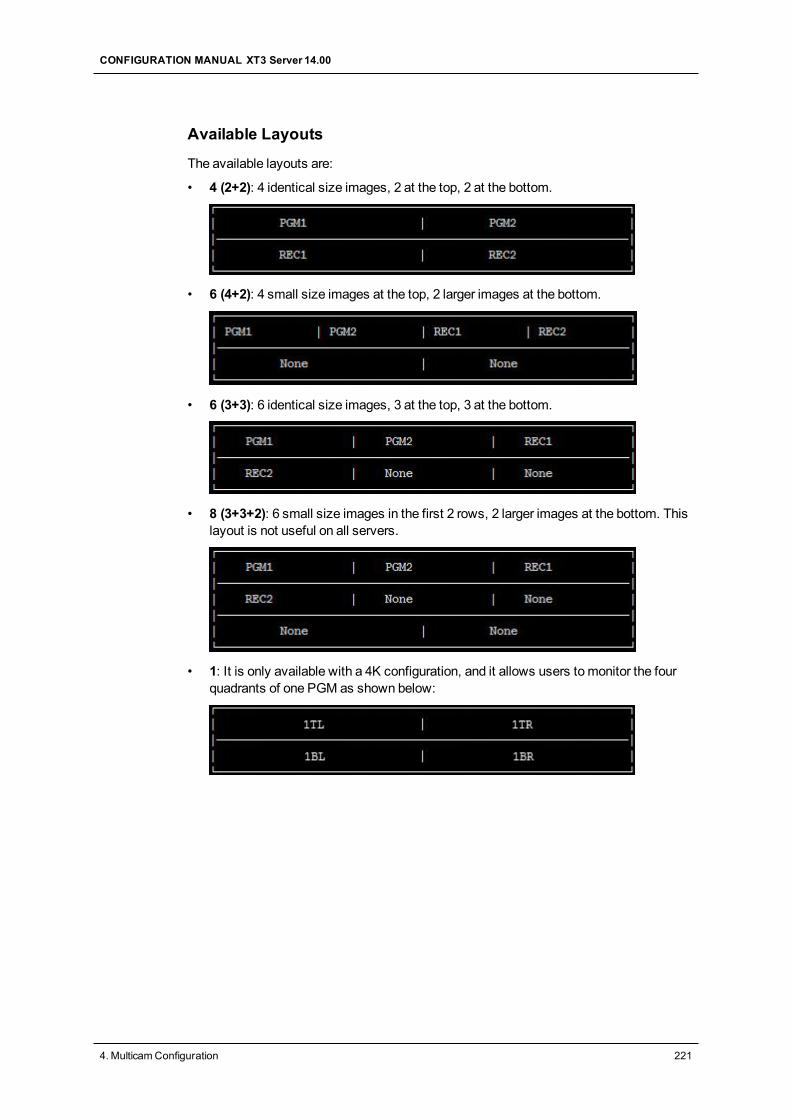
Available Layouts
The available layouts are:
• 4 (2+2): 4 identical size images, 2 at the top, 2 at the bottom.
• 6 (4+2): 4 small size images at the top, 2 larger images at the bottom.
• 6 (3+3): 6 identical size images, 3 at the top, 3 at the bottom.
• 8 (3+3+2): 6 small size images in the first 2 rows, 2 larger images at the bottom. Thislayout is not useful on all servers.
• 1: It is only available with a 4K configuration, and it allows users tomonitor the fourquadrants of one PGM as shown below:
CONFIGURATION MANUAL XT3 Server 14.00
4. MulticamConfiguration 221
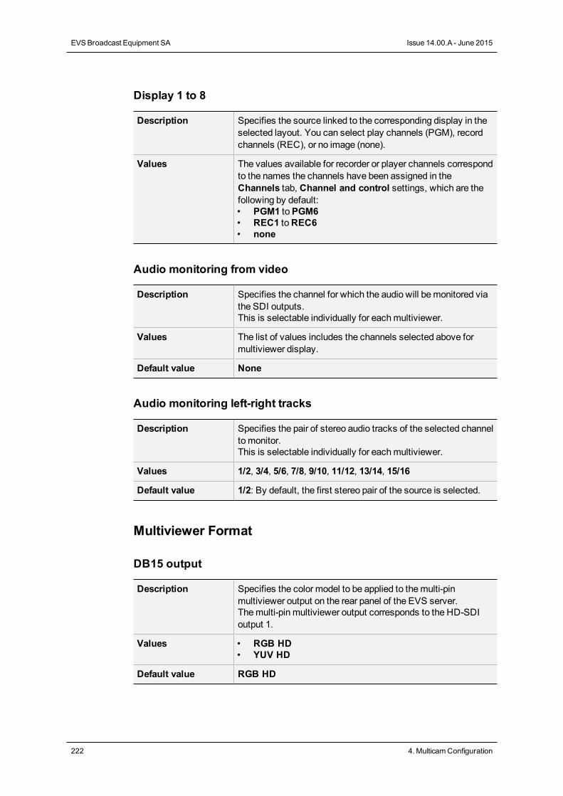
Display 1 to 8
Description Specifies the source linked to the corresponding display in theselected layout. You can select play channels (PGM), recordchannels (REC), or no image (none).
Values The values available for recorder or player channels correspondto the names the channels have been assigned in theChannels tab, Channel and control settings, which are thefollowing by default:• PGM1 toPGM6• REC1 toREC6• none
Audio monitoring from video
Description Specifies the channel for which the audio will bemonitored viathe SDI outputs.This is selectable individually for eachmultiviewer.
Values The list of values includes the channels selected above formultiviewer display.
Default value None
Audio monitoring left-right tracks
Description Specifies the pair of stereo audio tracks of the selected channelto monitor.This is selectable individually for eachmultiviewer.
Values 1/2, 3/4, 5/6, 7/8, 9/10, 11/12, 13/14, 15/16
Default value 1/2: By default, the first stereo pair of the source is selected.
Multiviewer Format
DB15 output
Description Specifies the color model to be applied to themulti-pinmultiviewer output on the rear panel of the EVS server.Themulti-pin multiviewer output corresponds to the HD-SDIoutput 1.
Values • RGB HD• YUV HD
Default value RGB HD
222 4. MulticamConfiguration
EVSBroadcast Equipment SA Issue 14.00.A - June 2015
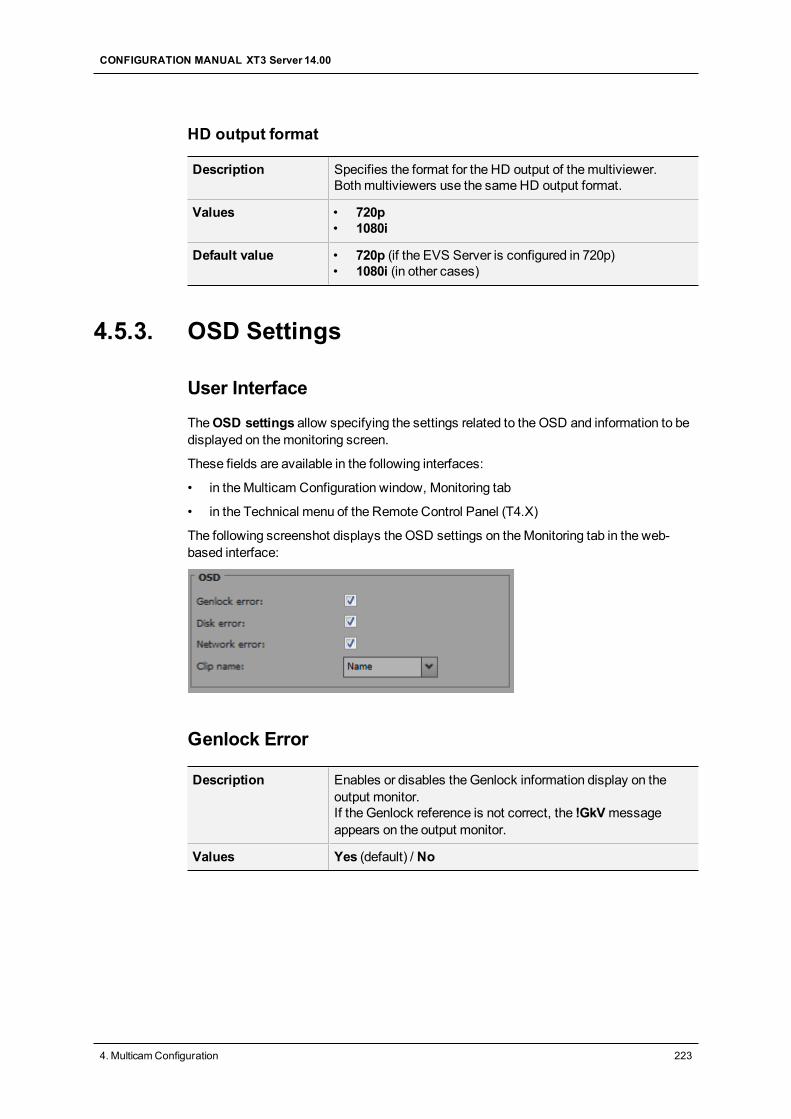
HD output format
Description Specifies the format for the HD output of themultiviewer.Bothmultiviewers use the sameHD output format.
Values • 720p• 1080i
Default value • 720p (if the EVS Server is configured in 720p)• 1080i (in other cases)
4.5.3. OSD Settings
User Interface
TheOSD settings allow specifying the settings related to the OSD and information to bedisplayed on themonitoring screen.
These fields are available in the following interfaces:
• in theMulticam Configuration window, Monitoring tab
• in the Technical menu of the Remote Control Panel (T4.X)
The following screenshot displays the OSD settings on theMonitoring tab in the web-based interface:
Genlock Error
Description Enables or disables the Genlock information display on theoutput monitor.If the Genlock reference is not correct, the !GkVmessageappears on the output monitor.
Values Yes (default) / No
CONFIGURATION MANUAL XT3 Server 14.00
4. MulticamConfiguration 223
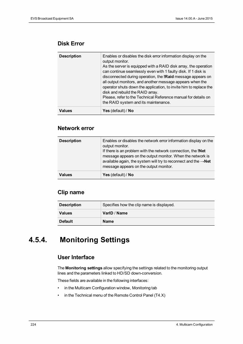
Disk Error
Description Enables or disables the disk error information display on theoutput monitor.As the server is equipped with a RAID disk array, the operationcan continue seamlessly even with 1 faulty disk. If 1 disk isdisconnected during operation, the !Raidmessage appears onall output monitors, and another message appears when theoperator shuts down the application, to invite him to replace thedisk and rebuild the RAID array.Please, refer to the Technical Referencemanual for details onthe RAID system and its maintenance.
Values Yes (default) / No
Network error
Description Enables or disables the network error information display on theoutput monitor.If there is an problem with the network connection, the !Netmessage appears on the output monitor. When the network isavailable again, the system will try to reconnect and the→Netmessage appears on the output monitor.
Values Yes (default) / No
Clip name
Description Specifies how the clip name is displayed.
Values VarID / Name
Default Name
4.5.4. Monitoring Settings
User Interface
TheMonitoring settings allow specifying the settings related to themonitoring outputlines and the parameters linked to HD/SD down-conversion.
These fields are available in the following interfaces:
• in theMulticam Configuration window, Monitoring tab
• in the Technical menu of the Remote Control Panel (T4.X)
224 4. MulticamConfiguration
EVSBroadcast Equipment SA Issue 14.00.A - June 2015
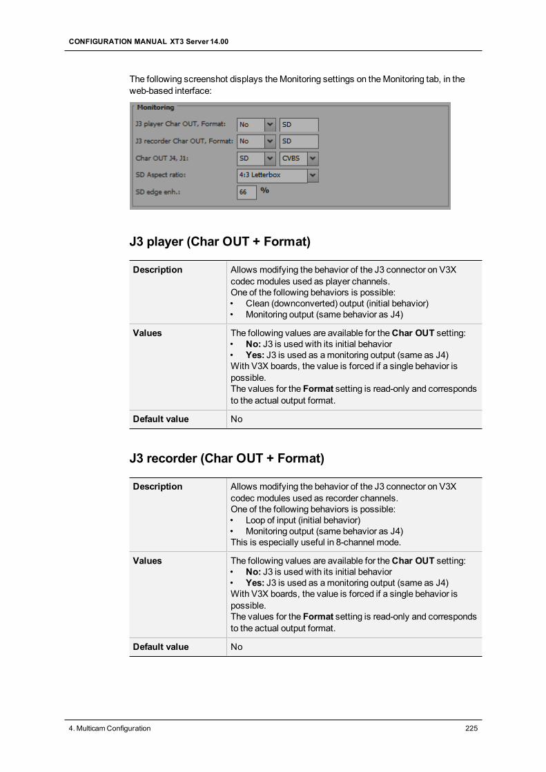
The following screenshot displays theMonitoring settings on theMonitoring tab, in theweb-based interface:
J3 player (Char OUT + Format)
Description Allows modifying the behavior of the J3 connector on V3Xcodec modules used as player channels.One of the following behaviors is possible:• Clean (downconverted) output (initial behavior)• Monitoring output (same behavior as J4)
Values The following values are available for theChar OUT setting:• No: J3 is used with its initial behavior• Yes: J3 is used as amonitoring output (same as J4)With V3X boards, the value is forced if a single behavior ispossible.The values for the Format setting is read-only and correspondsto the actual output format.
Default value No
J3 recorder (Char OUT + Format)
Description Allows modifying the behavior of the J3 connector on V3Xcodec modules used as recorder channels.One of the following behaviors is possible:• Loop of input (initial behavior)• Monitoring output (same behavior as J4)This is especially useful in 8-channel mode.
Values The following values are available for theChar OUT setting:• No: J3 is used with its initial behavior• Yes: J3 is used as amonitoring output (same as J4)With V3X boards, the value is forced if a single behavior ispossible.The values for the Format setting is read-only and correspondsto the actual output format.
Default value No
CONFIGURATION MANUAL XT3 Server 14.00
4. MulticamConfiguration 225

Char OUT J4
Description Specifies themonitoring output format generated on the J4connector.
Values • SD• HD (not supported in 1080p 3G Level A)• 3G
Default value System dependent
Char OUT J1
Description Specifies themonitoring output type generated on the J1connector.
Value • CVBS
SD aspect ratio
Availability This parameter is available when the EVS server is configuredin HD.
Description Specifies how the aspect ratio of HD video is converted in SD.
Values • 4:3 Letterbox: Black stripes are placed above and belowthe active video to compensate for the full width.
• 4:3 Crop: Left and right ends of the active video arecropped to compensate for the full height.
• 16:9: Corresponds to the HD aspect ratio. It is also calledanamorphic.
Default value 4:3 Letterbox
SD edge enhanc.
Description Defines the edge enhancer strength used when generating theSD downconverted output video.
Values 0 to 100
Default value 66
226 4. MulticamConfiguration
EVSBroadcast Equipment SA Issue 14.00.A - June 2015
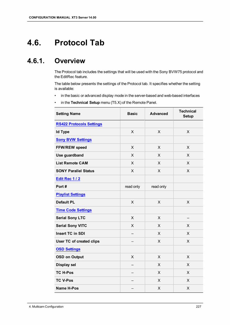
4.6. Protocol Tab
4.6.1. OverviewThe Protocol tab includes the settings that will be used with the Sony BVW75 protocol andthe EditRec feature.
The table below presents the settings of the Protocol tab. It specifies whether the settingis available:
• in the basic or advanced display mode in the server-based and web-based interfaces
• in the Technical Setupmenu (T5.X) of the Remote Panel.
Setting Name Basic Advanced TechnicalSetup
RS422 Protocols Settings
Id Type X X X
Sony BVW Settings
FFW/REW speed X X X
Use guardband X X X
List Remote CAM X X X
SONY Parallel Status X X X
Edit Rec 1 / 2
Port # read only read only
Playlist Settings
Default PL X X X
Time Code Settings
Serial Sony LTC X X –
Serial Sony VITC X X X
Insert TC in SDI – X X
User TC of created clips – X X
OSD Settings
OSD on Output X X X
Display sel – X X
TC H-Pos – X X
TC V-Pos – X X
Name H-Pos – X X
CONFIGURATION MANUAL XT3 Server 14.00
4. MulticamConfiguration 227
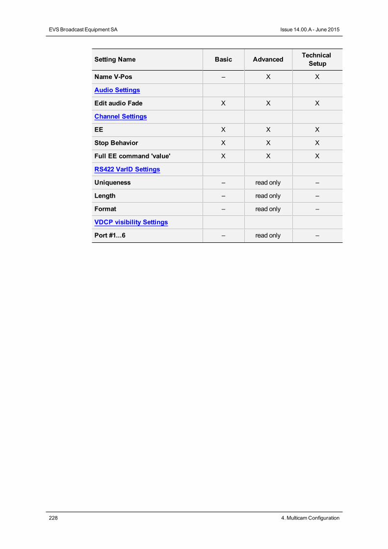
Setting Name Basic Advanced TechnicalSetup
Name V-Pos – X X
Audio Settings
Edit audio Fade X X X
Channel Settings
EE X X X
Stop Behavior X X X
Full EE command 'value' X X X
RS422 VarID Settings
Uniqueness – read only –
Length – read only –
Format – read only –
VDCP visibility Settings
Port #1...6 – read only –
228 4. MulticamConfiguration
EVSBroadcast Equipment SA Issue 14.00.A - June 2015
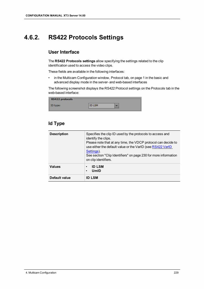
4.6.2. RS422 Protocols Settings
User Interface
TheRS422 Protocols settings allow specifying the settings related to the clipidentification used to access the video clips.
These fields are available in the following interfaces:
• in theMulticam Configuration window, Protocol tab, on page 1 in the basic andadvanced display mode in the server- and web-based interfaces
The following screenshot displays the RS422 Protocol settings on the Protocols tab in theweb-based interface:
Id Type
Description Specifies the clip ID used by the protocols to access andidentify the clips.Please note that at any time, the VDCP protocol can decide touse either the default value or the VarID (see RS422 VarIDSettings).See section "Clip Identifiers" on page 230 for more informationon clip identifiers.
Values • ID LSM• UmID
Default value ID LSM
CONFIGURATION MANUAL XT3 Server 14.00
4. MulticamConfiguration 229
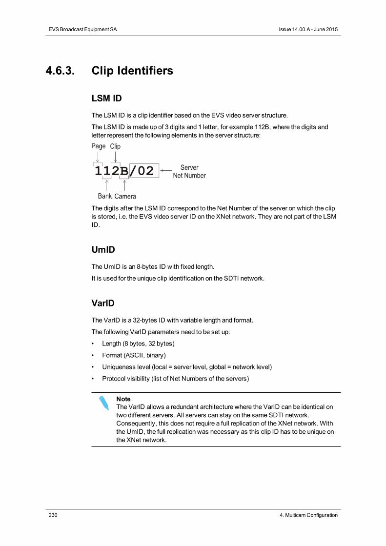
4.6.3. Clip Identifiers
LSM ID
The LSM ID is a clip identifier based on the EVS video server structure.
The LSM ID is made up of 3 digits and 1 letter, for example 112B, where the digits andletter represent the following elements in the server structure:
The digits after the LSM ID correspond to the Net Number of the server on which the clipis stored, i.e. the EVS video server ID on the XNet network. They are not part of the LSMID.
UmID
The UmID is an 8-bytes ID with fixed length.
It is used for the unique clip identification on the SDTI network.
VarID
The VarID is a 32-bytes ID with variable length and format.
The following VarID parameters need to be set up:
• Length (8 bytes, 32 bytes)
• Format (ASCII, binary)
• Uniqueness level (local = server level, global = network level)
• Protocol visibility (list of Net Numbers of the servers)
NoteThe VarID allows a redundant architecture where the VarID can be identical ontwo different servers. All servers can stay on the same SDTI network.Consequently, this does not require a full replication of the XNet network. Withthe UmID, the full replication was necessary as this clip ID has to be unique onthe XNet network.
230 4. MulticamConfiguration
EVSBroadcast Equipment SA Issue 14.00.A - June 2015
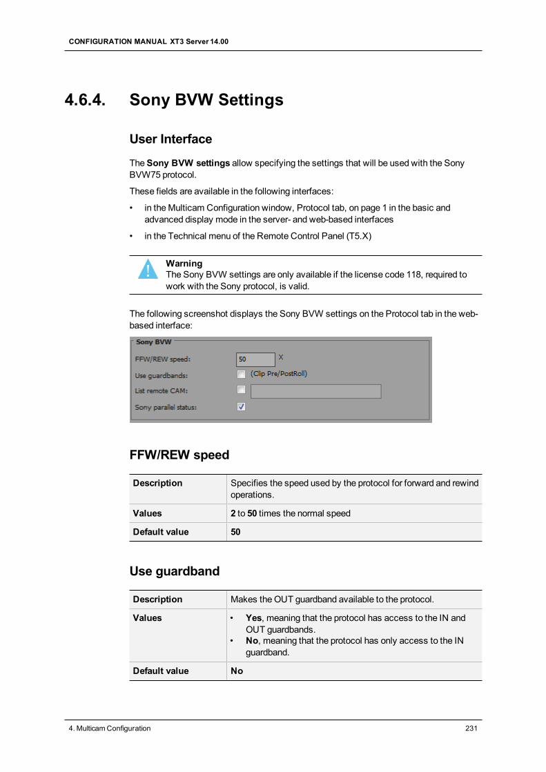
4.6.4. Sony BVW Settings
User Interface
TheSony BVW settings allow specifying the settings that will be used with the SonyBVW75 protocol.
These fields are available in the following interfaces:
• in theMulticam Configuration window, Protocol tab, on page 1 in the basic andadvanced display mode in the server- and web-based interfaces
• in the Technical menu of the Remote Control Panel (T5.X)
WarningThe Sony BVW settings are only available if the license code 118, required towork with the Sony protocol, is valid.
The following screenshot displays the Sony BVW settings on the Protocol tab in the web-based interface:
FFW/REW speed
Description Specifies the speed used by the protocol for forward and rewindoperations.
Values 2 to 50 times the normal speed
Default value 50
Use guardband
Description Makes the OUT guardband available to the protocol.
Values • Yes, meaning that the protocol has access to the IN andOUT guardbands.
• No, meaning that the protocol has only access to the INguardband.
Default value No
CONFIGURATION MANUAL XT3 Server 14.00
4. MulticamConfiguration 231
List Remote CAM
Description Allows access to the CAM recorders of the remote serverspecified in the XNet field.
Values • Yes, meaning that the recorders of the local server and theremote server are available.
• No, meaning that only the recorders of the local server areavailable.
Default value No
SONY Parallel Status
Description Activates the Sony serial connection status reporting whenseveral controllers are used in parallel mode.
Values Yes / No
Default value Yes
4.6.5. EditRec
Introduction to Edit Rec
Edit Rec Protocol
The Edit Rec is a linear editing engine associated to a play channel and a record channelon a server. Its role is to emulate a VTR. The Edit Rec engine relies on the Edit Recprotocol. In addition, both the play and the record channels of the Edit Rec engine areassociated to the sameRS422 port.
For more information on the Edit Rec feature, refer to the Edit Rec manual.
Overview on Edit Rec Settings
TheEdit Rec settings allow specifying the settings that will be used by the Edit Recfeature.
The Edit Rec settings are available in the following interfaces:
• in theMulticam Configuration window, Protocol tab, on page 2 for Edit Rec 1 and onpage 3 for Edit Rec 2, in the basic and advanced display mode in the server- and web-based interfaces
• in the Technical menu of the Remote Control Panel, pages T5.X for Edit Rec 1 andEdit Rec 2
232 4. MulticamConfiguration
EVSBroadcast Equipment SA Issue 14.00.A - June 2015
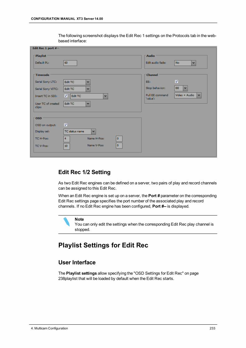
The following screenshot displays the Edit Rec 1 settings on the Protocols tab in the web-based interface:
Edit Rec 1/2 Setting
As two Edit Rec engines can be defined on a server, two pairs of play and record channelscan be assigned to this Edit Rec.
When an Edit Rec engine is set up on a server, thePort # parameter on the correspondingEdit Rec settings page specifies the port number of the associated play and recordchannels. If no Edit Rec engine has been configured, Port #-- is displayed.
NoteYou can only edit the settings when the corresponding Edit Rec play channel isstopped.
Playlist Settings for Edit Rec
User Interface
ThePlaylist settings allow specifying the "OSD Settings for Edit Rec" on page238playlist that will be loaded by default when the Edit Rec starts.
CONFIGURATION MANUAL XT3 Server 14.00
4. MulticamConfiguration 233
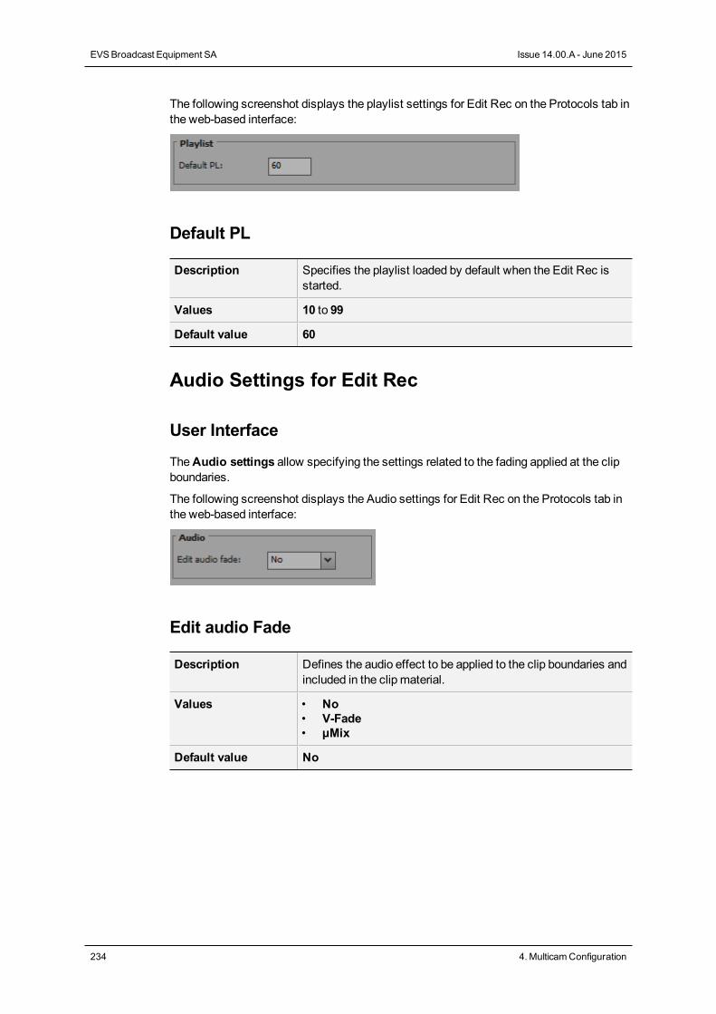
The following screenshot displays the playlist settings for Edit Rec on the Protocols tab inthe web-based interface:
Default PL
Description Specifies the playlist loaded by default when the Edit Rec isstarted.
Values 10 to 99
Default value 60
Audio Settings for Edit Rec
User Interface
TheAudio settings allow specifying the settings related to the fading applied at the clipboundaries.
The following screenshot displays the Audio settings for Edit Rec on the Protocols tab inthe web-based interface:
Edit audio Fade
Description Defines the audio effect to be applied to the clip boundaries andincluded in the clip material.
Values • No• V-Fade• µMix
Default value No
234 4. MulticamConfiguration
EVSBroadcast Equipment SA Issue 14.00.A - June 2015
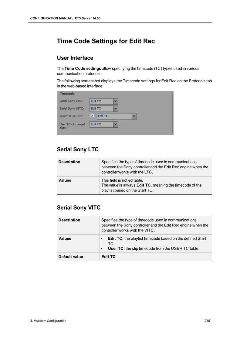
Time Code Settings for Edit Rec
User Interface
The Time Code settings allow specifying the timecode (TC) types used in variouscommunication protocols.
The following screenshot displays the Timecode settings for Edit Rec on the Protocols tabin the web-based interface:
Serial Sony LTC
Description Specifies the type of timecode used in communicationsbetween the Sony controller and the Edit Rec engine when thecontroller works with the LTC.
Values This field is not editable.The value is always Edit TC, meaning the timecode of theplaylist based on the Start TC.
Serial Sony VITC
Description Specifies the type of timecode used in communicationsbetween the Sony controller and the Edit Rec engine when thecontroller works with the VITC.
Values • Edit TC, the playlist timecode based on the defined StartTC.
• User TC, the clip timecode from the USER TC table.
Default value Edit TC
CONFIGURATION MANUAL XT3 Server 14.00
4. MulticamConfiguration 235
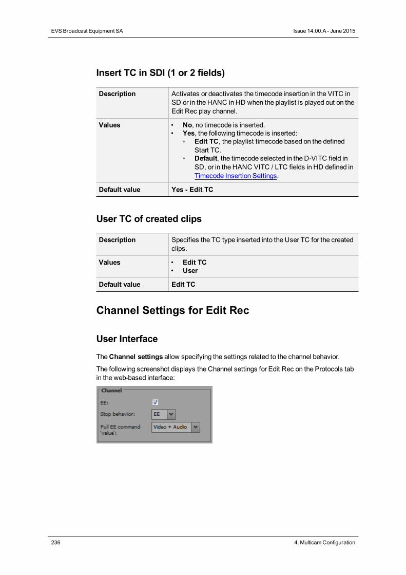
Insert TC in SDI (1 or 2 fields)
Description Activates or deactivates the timecode insertion in the VITC inSD or in the HANC in HD when the playlist is played out on theEdit Rec play channel.
Values • No, no timecode is inserted.• Yes, the following timecode is inserted:
◦ Edit TC, the playlist timecode based on the definedStart TC.
◦ Default, the timecode selected in the D-VITC field inSD, or in the HANC VITC / LTC fields in HD defined inTimecode Insertion Settings.
Default value Yes - Edit TC
User TC of created clips
Description Specifies the TC type inserted into the User TC for the createdclips.
Values • Edit TC• User
Default value Edit TC
Channel Settings for Edit Rec
User Interface
TheChannel settings allow specifying the settings related to the channel behavior.
The following screenshot displays the Channel settings for Edit Rec on the Protocols tabin the web-based interface:
236 4. MulticamConfiguration
EVSBroadcast Equipment SA Issue 14.00.A - June 2015
EE
Description Activates the EE (Electronic to Electronic) mode, the signalbeing recorded is played on the output channel without anydelay.
Values Yes / No
Default Value Yes
Stop Behavior
Description Defines the channel behavior when it is in stopmode.
Values • PB (playback): The EditRec playlist is displayed on theEditRec output.
• EE: The EditRec input passes through the server and isdisplayed on the EditRec output.
Default Value PB
Full EE command 'value'
Description Allows to specify whether the Full EE command is applied onthe audio and/or to the video.The Full EE commandmakes it possible to view the sourceconnected to the EditRec through the EditRec outputs withoutany audio or video delay.From a practical point of view, this command allows theoperator to select the IN andOUT points of the sources and ofthe recorder from a single monitoring window (EditRec output).
Values The following values are available:• Video+Audio:When the EVS server receives the Full EE
command, it is applied to the video and audio feeds.• Audio:When the EVS server receives the Full EE
command, it is applied to the audio feeds only. This isrelevant with the Sony plugin Editor.
Default Value Video + Audio
CONFIGURATION MANUAL XT3 Server 14.00
4. MulticamConfiguration 237
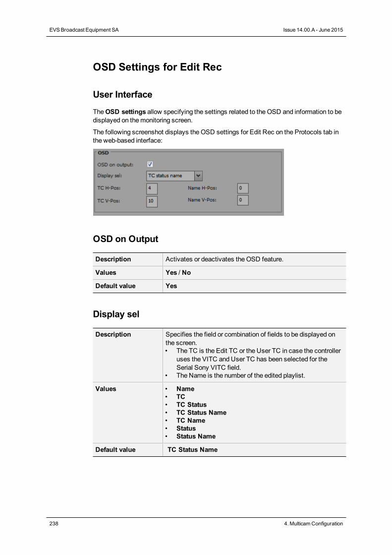
OSD Settings for Edit Rec
User Interface
TheOSD settings allow specifying the settings related to the OSD and information to bedisplayed on themonitoring screen.
The following screenshot displays the OSD settings for Edit Rec on the Protocols tab inthe web-based interface:
OSD on Output
Description Activates or deactivates the OSD feature.
Values Yes / No
Default value Yes
Display sel
Description Specifies the field or combination of fields to be displayed onthe screen.• The TC is the Edit TC or the User TC in case the controller
uses the VITC and User TC has been selected for theSerial Sony VITC field.
• The Name is the number of the edited playlist.
Values • Name• TC• TC Status• TC Status Name• TC Name• Status• Status Name
Default value TC Status Name
238 4. MulticamConfiguration
EVSBroadcast Equipment SA Issue 14.00.A - June 2015
TC H-Pos
Description Defines the horizontal position of the TC on the screen.
Values 0 to 9
Default value 4
Name H-Pos
Description Defines the horizontal position of the edit name on the screen.
Values 0 to 15
Default value 0
TC V-Pos
Description Defines the vertical position of the TC on the screen.
Values 0 to 11
Default value 10
Name V-Pos
Description Defines the vertical position of the edit name on the screen.
Values 0 to 11
Default value 0
4.6.6. RS422 VarID Settings
User Interface
TheRS422 VarID settings and theVDCP visibility settings display the read-only VarIDsettings.
These fields are available in the following interfaces:
• in theMulticam Configuration window, Protocol tab in the advanced display mode inthe server- and web-based interfaces.
WarningThe VDCP visibility settings are only available if the license code 119, requiredto work with the VDCP protocol, is valid.
CONFIGURATION MANUAL XT3 Server 14.00
4. MulticamConfiguration 239
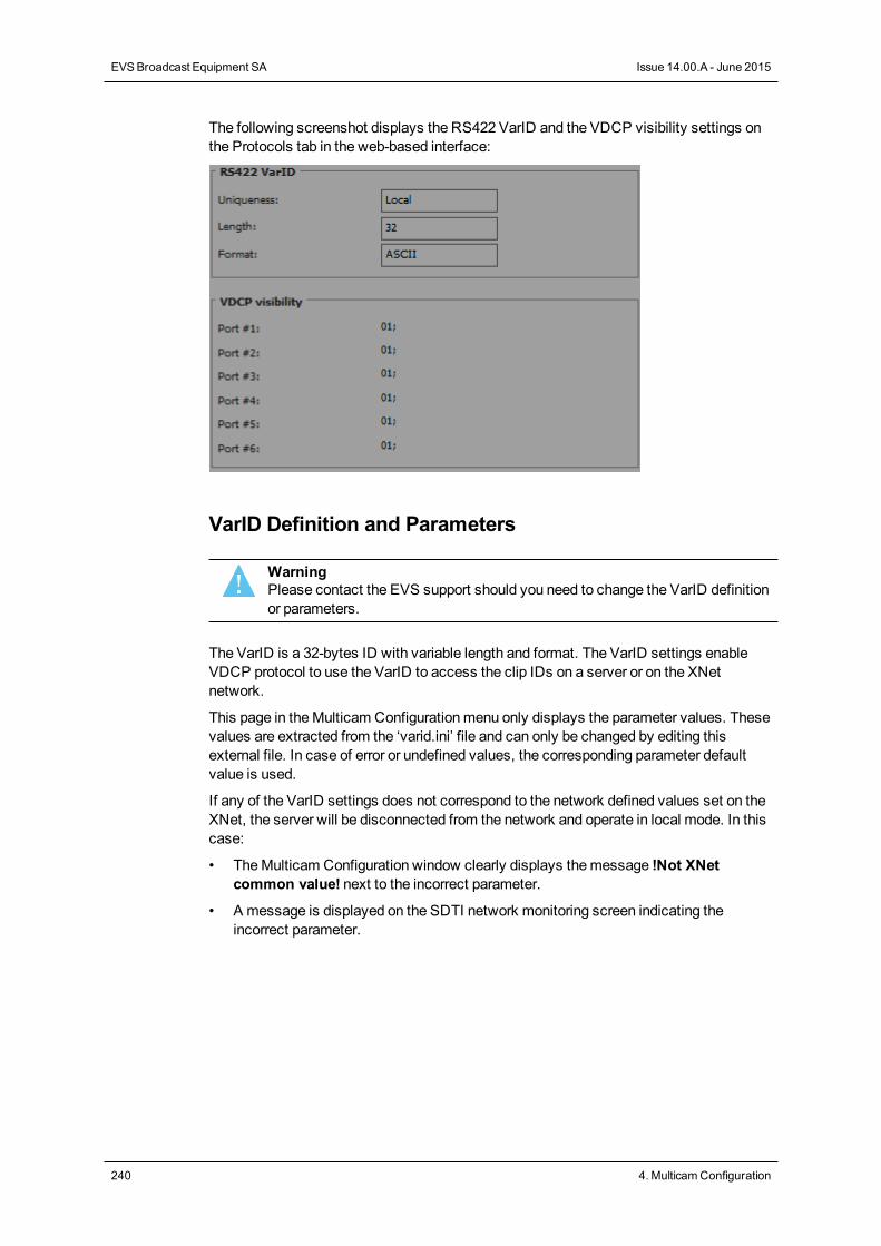
The following screenshot displays the RS422 VarID and the VDCP visibility settings onthe Protocols tab in the web-based interface:
VarID Definition and Parameters
WarningPlease contact the EVS support should you need to change the VarID definitionor parameters.
The VarID is a 32-bytes ID with variable length and format. The VarID settings enableVDCP protocol to use the VarID to access the clip IDs on a server or on the XNetnetwork.
This page in theMulticam Configurationmenu only displays the parameter values. Thesevalues are extracted from the ‘varid.ini’ file and can only be changed by editing thisexternal file. In case of error or undefined values, the corresponding parameter defaultvalue is used.
If any of the VarID settings does not correspond to the network defined values set on theXNet, the server will be disconnected from the network and operate in local mode. In thiscase:
• TheMulticam Configuration window clearly displays themessage !Not XNetcommon value! next to the incorrect parameter.
• A message is displayed on the SDTI network monitoring screen indicating theincorrect parameter.
240 4. MulticamConfiguration
EVSBroadcast Equipment SA Issue 14.00.A - June 2015
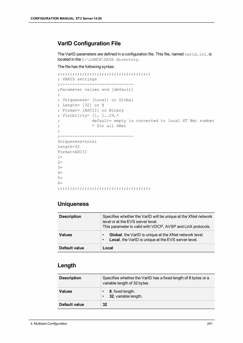
VarID Configuration File
The VarID parameters are defined in a configuration file. This file, named varid.ini, islocated in the C:\LSMCE\DATA directory.
The file has the following syntax:
;;;;;;;;;;;;;;;;;;;;;;;;;;;;;;;;;;;;;;; VARID settings;------------------------------;Parameter values and [default];; Uniqueness= [Local] or Global; Length= [32] or 8; Format= [ASCII] or Binary; Visibility= [], 1..29,*; default= empty is converted to local XT Net number; * for all XNet;;------------------------------Uniqueness=LocalLength=32Format=ASCII1=2=3=4=5=6=;;;;;;;;;;;;;;;;;;;;;;;;;;;;;;;;;;;;;;
Uniqueness
Description Specifies whether the VarID will be unique at the XNet networklevel or at the EVS server level.This parameter is valid with VDCP, AVSP and LinX protocols.
Values • Global, the VarID is unique at the XNet network level.• Local, the VarID is unique at the EVS server level.
Default value Local
Length
Description Specifies whether the VarID has a fixed length of 8 bytes or avariable length of 32 bytes.
Values • 8, fixed length.• 32, variable length.
Default value 32
CONFIGURATION MANUAL XT3 Server 14.00
4. MulticamConfiguration 241
Format
Description Specifies whether the VarID has an ASCII or binary format.
Values • ASCII• Binary
Default value ASCII
VDCP Visibility
Description Specifies the list of servers which will be visible on the variouscommunication ports that the VDCP protocol will use tocommunicate with. This parameter is only relevant for theVDCP protocol.For a list of servers, use the corresponding servers XNetnumbers separated with a semi-colon (;). Please note that thelist order is taken into account in the visibility. This means thatthe system first searches for the requested clips on the firstserver of the list, then on the second, and so on.
Values • (empty), the local server is used (converted to the localXNet number).
• 1 to 29, the servers available on XNet.• *, for all XNet servers.
Default value 1
242 4. MulticamConfiguration
EVSBroadcast Equipment SA Issue 14.00.A - June 2015
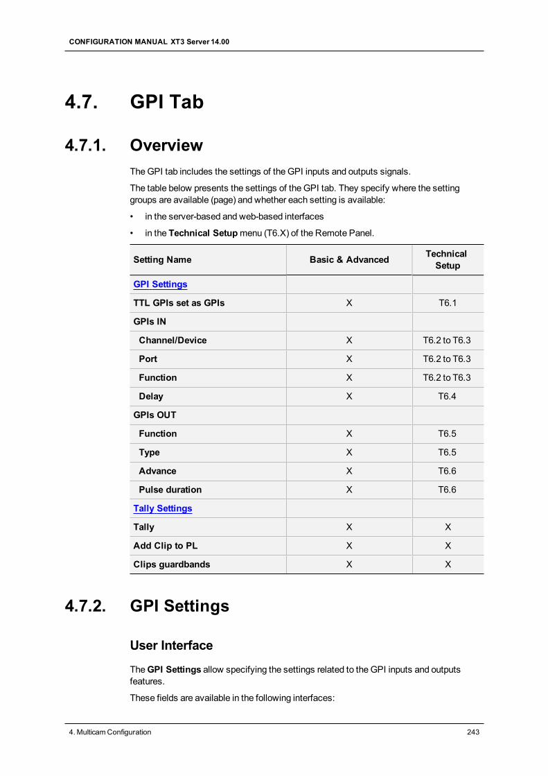
4.7. GPI Tab
4.7.1. OverviewTheGPI tab includes the settings of the GPI inputs and outputs signals.
The table below presents the settings of the GPI tab. They specify where the settinggroups are available (page) and whether each setting is available:
• in the server-based and web-based interfaces
• in the Technical Setupmenu (T6.X) of the Remote Panel.
Setting Name Basic & Advanced TechnicalSetup
GPI Settings
TTL GPIs set as GPIs X T6.1
GPIs IN
Channel/Device X T6.2 to T6.3
Port X T6.2 to T6.3
Function X T6.2 to T6.3
Delay X T6.4
GPIs OUT
Function X T6.5
Type X T6.5
Advance X T6.6
Pulse duration X T6.6
Tally Settings
Tally X X
Add Clip to PL X X
Clips guardbands X X
4.7.2. GPI Settings
User Interface
TheGPI Settings allow specifying the settings related to the GPI inputs and outputsfeatures.
These fields are available in the following interfaces:
CONFIGURATION MANUAL XT3 Server 14.00
4. MulticamConfiguration 243
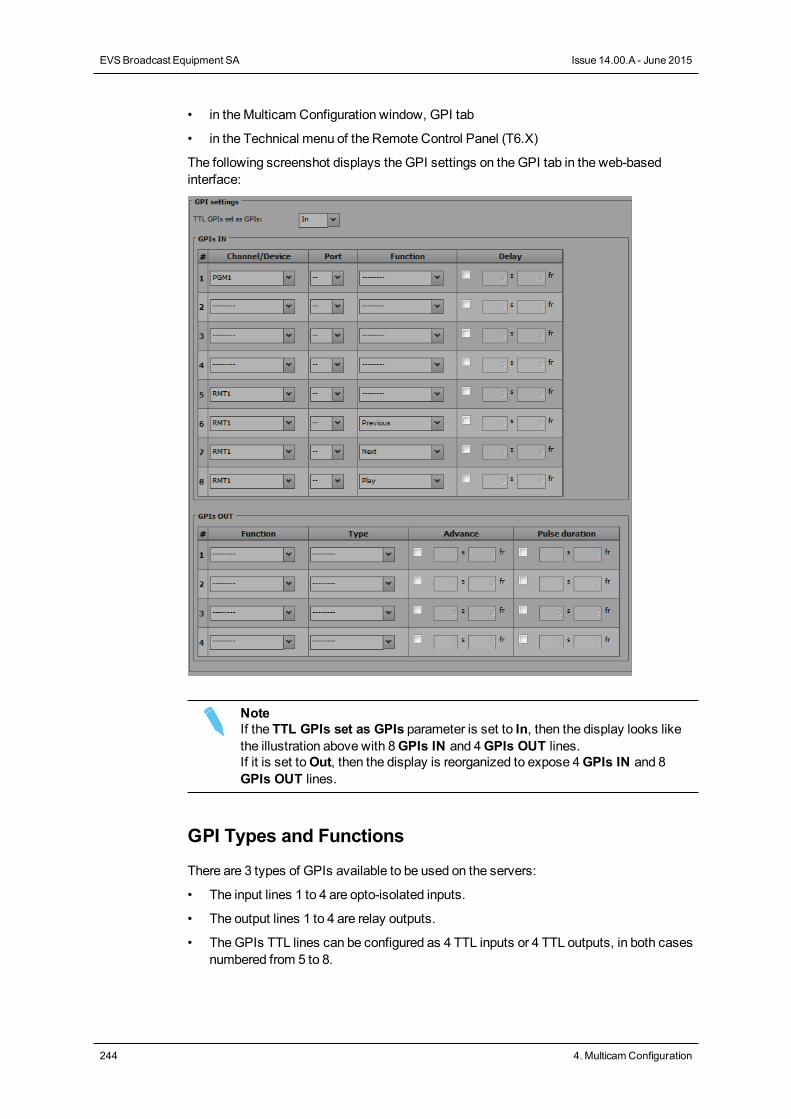
• in theMulticam Configuration window, GPI tab
• in the Technical menu of the Remote Control Panel (T6.X)
The following screenshot displays the GPI settings on theGPI tab in the web-basedinterface:
NoteIf the TTL GPIs set as GPIs parameter is set to In, then the display looks likethe illustration above with 8GPIs IN and 4GPIs OUT lines.If it is set toOut, then the display is reorganized to expose 4GPIs IN and 8GPIs OUT lines.
GPI Types and Functions
There are 3 types of GPIs available to be used on the servers:
• The input lines 1 to 4 are opto-isolated inputs.
• The output lines 1 to 4 are relay outputs.
• TheGPIs TTL lines can be configured as 4 TTL inputs or 4 TTL outputs, in both casesnumbered from 5 to 8.
244 4. MulticamConfiguration
EVSBroadcast Equipment SA Issue 14.00.A - June 2015
According to the protocol you are using, the following functions are available and can beassigned to the GPIs lines as described hereunder in the Function parameter.
• AVSP: Play, Stop, Still, Recue, GotoClipIN, GotoClipOUT, Next, Skip.
• Sony: Play, Pause, Recue, Previous, Next, Skip.
• DD35: Play, Pause, Recue, Previous, Next, Skip.
• Odetics: Play, Pause, Recue, Next.
• VDCP: Play, Pause, Recue, Previous, Next, Skip.
NoteFor all protocols, except AVSP, use the channel assignment (PGM1 to PGM6)instead of the device protocol type (Sony BVW75, Odetics).The AVSP protocol does not require any GPI IN setting in this page as they aredefined through specific serial AVSP commands. For this reason, specificAVSP commands will not be available via the Function parameter for the GPIsIN.
TTL GPIs set as GPIs
Description Defines the 4 configurable GPIs as inputs or outputs.
Values In / Out
Default value In
GPIs IN - Channel/Device
Description Specifies the server channel or the external device connectedto the corresponding GPI input line, and therefore to whichchannel or device the GPI will be sent to.
Values The following values are possible and correspond to one of thechannels or controllers assigned in the Channel and Controlsettings (Channels tab, page 1):• PGMx: TheGPI is sent to the specified play channel.• RECx: TheGPI is sent to the specified record channel.• RMTx: TheGPI is sent to the remote controller.• <Protocol Name>: TheGPI is sent to the third-party
controlling device.
CONFIGURATION MANUAL XT3 Server 14.00
4. MulticamConfiguration 245
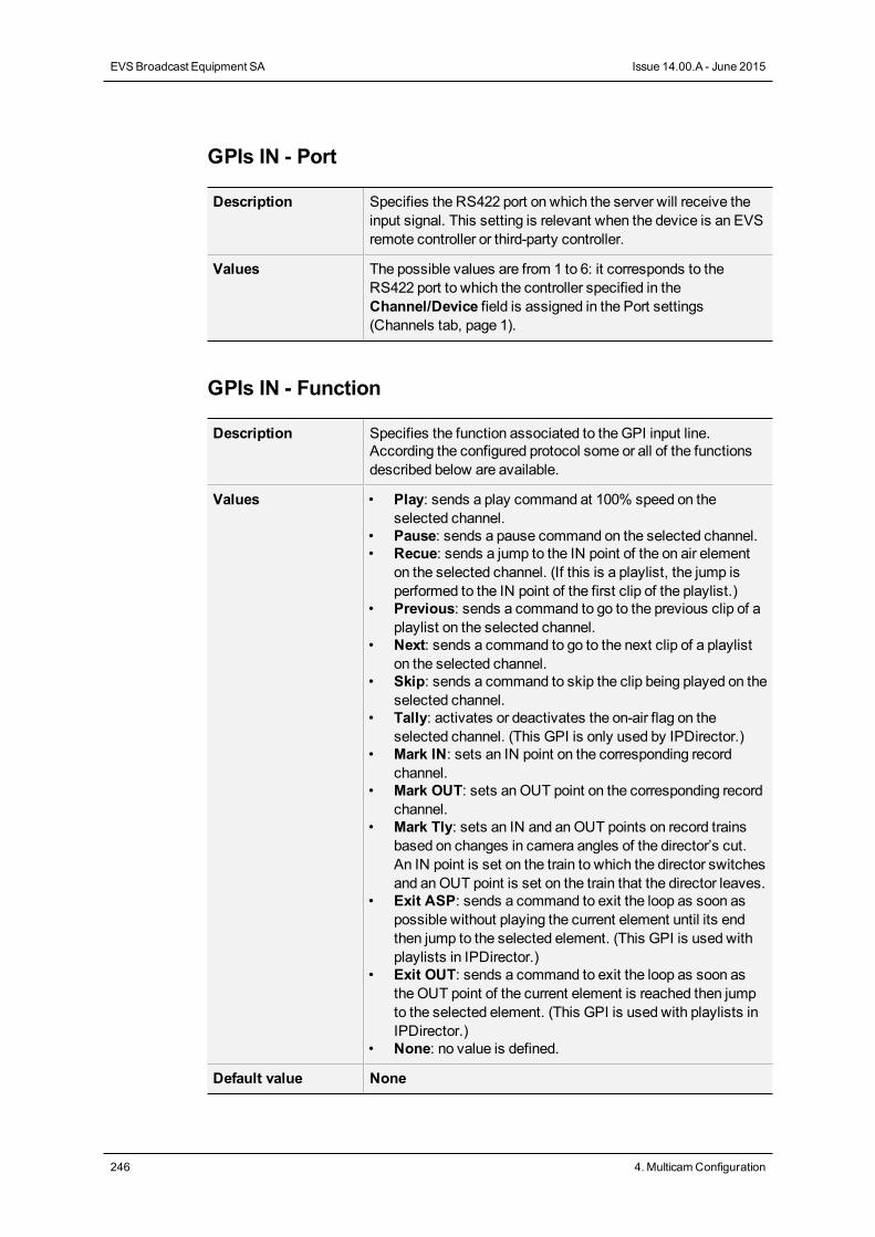
GPIs IN - Port
Description Specifies the RS422 port on which the server will receive theinput signal. This setting is relevant when the device is an EVSremote controller or third-party controller.
Values The possible values are from 1 to 6: it corresponds to theRS422 port to which the controller specified in theChannel/Device field is assigned in the Port settings(Channels tab, page 1).
GPIs IN - Function
Description Specifies the function associated to the GPI input line.According the configured protocol some or all of the functionsdescribed below are available.
Values • Play: sends a play command at 100% speed on theselected channel.
• Pause: sends a pause command on the selected channel.• Recue: sends a jump to the IN point of the on air element
on the selected channel. (If this is a playlist, the jump isperformed to the IN point of the first clip of the playlist.)
• Previous: sends a command to go to the previous clip of aplaylist on the selected channel.
• Next: sends a command to go to the next clip of a playliston the selected channel.
• Skip: sends a command to skip the clip being played on theselected channel.
• Tally: activates or deactivates the on-air flag on theselected channel. (This GPI is only used by IPDirector.)
• Mark IN: sets an IN point on the corresponding recordchannel.
• Mark OUT: sets anOUT point on the corresponding recordchannel.
• Mark Tly: sets an IN and anOUT points on record trainsbased on changes in camera angles of the director’s cut.An IN point is set on the train to which the director switchesand anOUT point is set on the train that the director leaves.
• Exit ASP: sends a command to exit the loop as soon aspossible without playing the current element until its endthen jump to the selected element. (This GPI is used withplaylists in IPDirector.)
• Exit OUT: sends a command to exit the loop as soon asthe OUT point of the current element is reached then jumpto the selected element. (This GPI is used with playlists inIPDirector.)
• None: no value is defined.
Default value None
246 4. MulticamConfiguration
EVSBroadcast Equipment SA Issue 14.00.A - June 2015
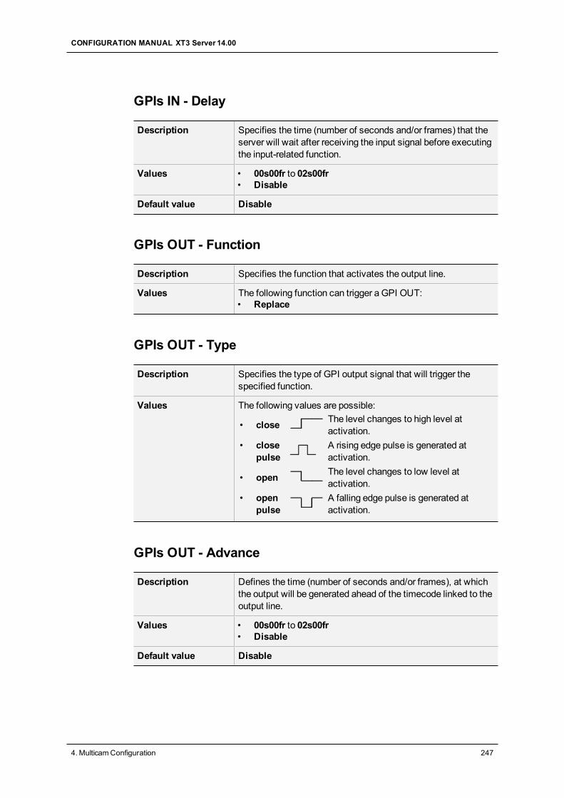
GPIs IN - Delay
Description Specifies the time (number of seconds and/or frames) that theserver will wait after receiving the input signal before executingthe input-related function.
Values • 00s00fr to 02s00fr• Disable
Default value Disable
GPIs OUT - Function
Description Specifies the function that activates the output line.
Values The following function can trigger a GPI OUT:• Replace
GPIs OUT - Type
Description Specifies the type of GPI output signal that will trigger thespecified function.
Values The following values are possible:
• close The level changes to high level atactivation.
• closepulse
A rising edge pulse is generated atactivation.
• open The level changes to low level atactivation.
• openpulse
A falling edge pulse is generated atactivation.
GPIs OUT - Advance
Description Defines the time (number of seconds and/or frames), at whichthe output will be generated ahead of the timecode linked to theoutput line.
Values • 00s00fr to 02s00fr• Disable
Default value Disable
CONFIGURATION MANUAL XT3 Server 14.00
4. MulticamConfiguration 247
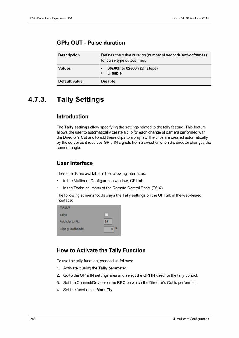
GPIs OUT - Pulse duration
Description Defines the pulse duration (number of seconds and/or frames)for pulse type output lines.
Values • 00s00fr to 02s00fr (2fr steps)• Disable
Default value Disable
4.7.3. Tally Settings
Introduction
The Tally settings allow specifying the settings related to the tally feature. This featureallows the user to automatically create a clip for each change of camera performed withthe Director’s Cut and to add these clips to a playlist. The clips are created automaticallyby the server as it receives GPIs IN signals from a switcher when the director changes thecamera angle.
User Interface
These fields are available in the following interfaces:
• in theMulticam Configuration window, GPI tab
• in the Technical menu of the Remote Control Panel (T6.X)
The following screenshot displays the Tally settings on theGPI tab in the web-basedinterface:
How to Activate the Tally Function
To use the tally function, proceed as follows:
1. Activate it using the Tally parameter.
2. Go to the GPIs IN settings area and select the GPI IN used for the tally control.
3. Set the Channel/Device on the REC onwhich the Director’s Cut is performed.
4. Set the function as Mark Tly.
248 4. MulticamConfiguration
EVSBroadcast Equipment SA Issue 14.00.A - June 2015
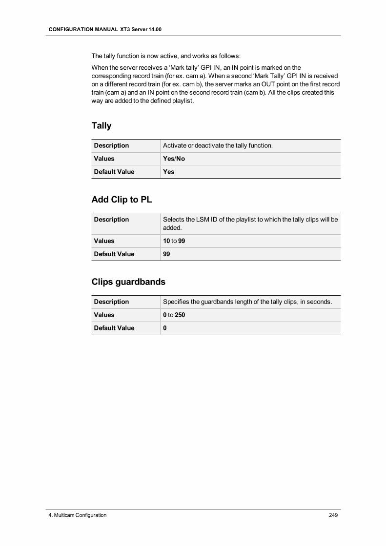
The tally function is now active, and works as follows:
When the server receives a ‘Mark tally’ GPI IN, an IN point is marked on thecorresponding record train (for ex. cam a). When a second ‘Mark Tally’ GPI IN is receivedon a different record train (for ex. cam b), the server marks anOUT point on the first recordtrain (cam a) and an IN point on the second record train (cam b). All the clips created thisway are added to the defined playlist.
Tally
Description Activate or deactivate the tally function.
Values Yes/No
Default Value Yes
Add Clip to PL
Description Selects the LSM ID of the playlist to which the tally clips will beadded.
Values 10 to 99
Default Value 99
Clips guardbands
Description Specifies the guardbands length of the tally clips, in seconds.
Values 0 to 250
Default Value 0
CONFIGURATION MANUAL XT3 Server 14.00
4. MulticamConfiguration 249
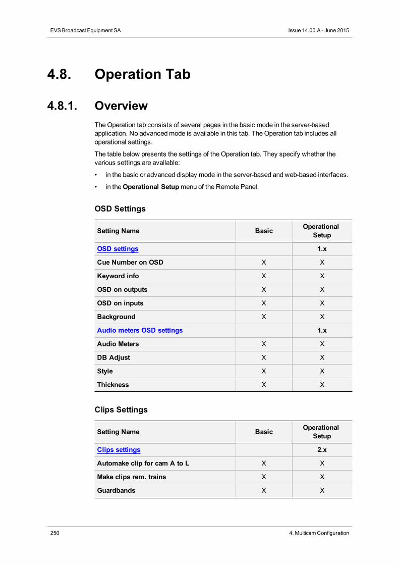
4.8. Operation Tab
4.8.1. OverviewTheOperation tab consists of several pages in the basic mode in the server-basedapplication. No advancedmode is available in this tab. TheOperation tab includes alloperational settings.
The table below presents the settings of the Operation tab. They specify whether thevarious settings are available:
• in the basic or advanced display mode in the server-based and web-based interfaces.
• in theOperational Setupmenu of the Remote Panel.
OSD Settings
Setting Name Basic OperationalSetup
OSD settings 1.x
Cue Number on OSD X X
Keyword info X X
OSD on outputs X X
OSD on inputs X X
Background X X
Audio meters OSD settings 1.x
Audio Meters X X
DB Adjust X X
Style X X
Thickness X X
Clips Settings
Setting Name Basic OperationalSetup
Clips settings 2.x
Automake clip for cam A to L X X
Make clips rem. trains X X
Guardbands X X
250 4. MulticamConfiguration
EVSBroadcast Equipment SA Issue 14.00.A - June 2015
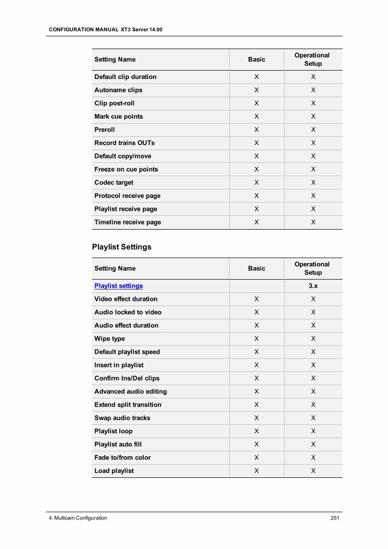
Setting Name Basic OperationalSetup
Default clip duration X X
Autoname clips X X
Clip post-roll X X
Mark cue points X X
Preroll X X
Record trains OUTs X X
Default copy/move X X
Freeze on cue points X X
Codec target X X
Protocol receive page X X
Playlist receive page X X
Timeline receive page X X
Playlist Settings
Setting Name Basic OperationalSetup
Playlist settings 3.x
Video effect duration X X
Audio locked to video X X
Audio effect duration X X
Wipe type X X
Default playlist speed X X
Insert in playlist X X
Confirm Ins/Del clips X X
Advanced audio editing X X
Extend split transition X X
Swap audio tracks X X
Playlist loop X X
Playlist auto fill X X
Fade to/from color X X
Load playlist X X
CONFIGURATION MANUAL XT3 Server 14.00
4. MulticamConfiguration 251
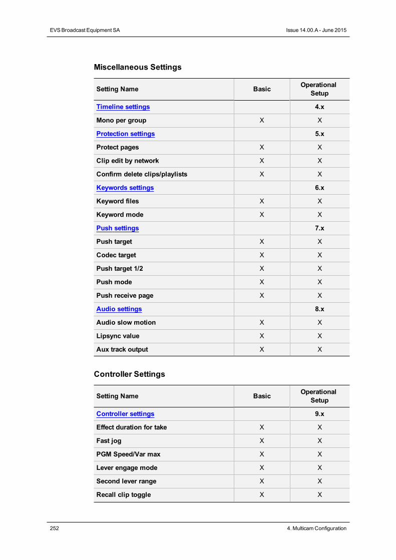
Miscellaneous Settings
Setting Name Basic OperationalSetup
Timeline settings 4.x
Mono per group X X
Protection settings 5.x
Protect pages X X
Clip edit by network X X
Confirm delete clips/playlists X X
Keywords settings 6.x
Keyword files X X
Keyword mode X X
Push settings 7.x
Push target X X
Codec target X X
Push target 1/2 X X
Push mode X X
Push receive page X X
Audio settings 8.x
Audio slow motion X X
Lipsync value X X
Aux track output X X
Controller Settings
Setting Name Basic OperationalSetup
Controller settings 9.x
Effect duration for take X X
Fast jog X X
PGM Speed/Var max X X
Lever engage mode X X
Second lever range X X
Recall clip toggle X X
252 4. MulticamConfiguration
EVSBroadcast Equipment SA Issue 14.00.A - June 2015
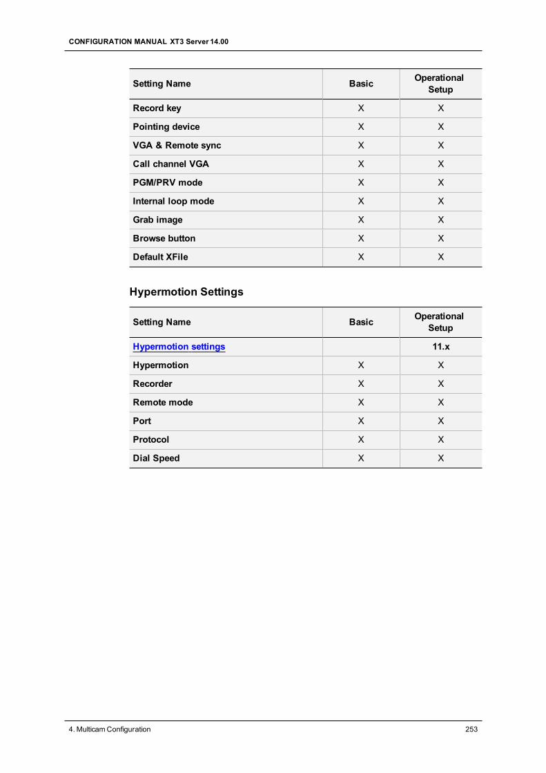
Setting Name Basic OperationalSetup
Record key X X
Pointing device X X
VGA & Remote sync X X
Call channel VGA X X
PGM/PRV mode X X
Internal loop mode X X
Grab image X X
Browse button X X
Default XFile X X
Hypermotion Settings
Setting Name Basic OperationalSetup
Hypermotion settings 11.x
Hypermotion X X
Recorder X X
Remote mode X X
Port X X
Protocol X X
Dial Speed X X
CONFIGURATION MANUAL XT3 Server 14.00
4. MulticamConfiguration 253
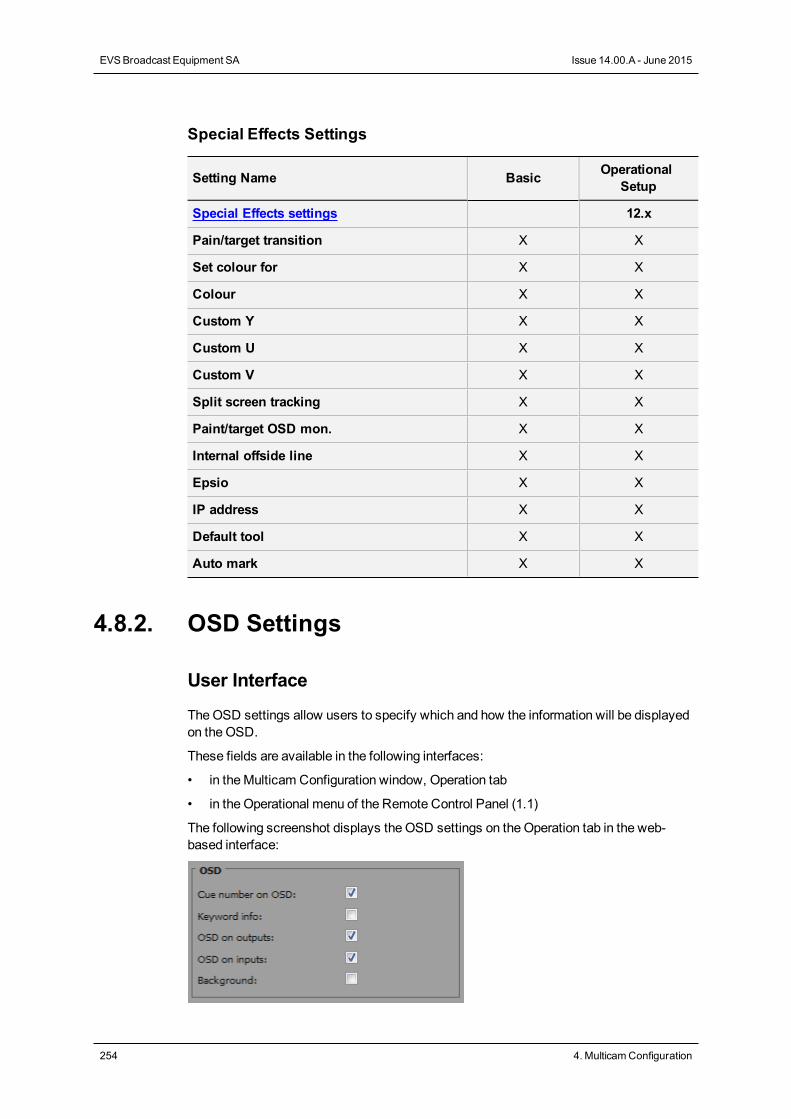
Special Effects Settings
Setting Name Basic OperationalSetup
Special Effects settings 12.x
Pain/target transition X X
Set colour for X X
Colour X X
Custom Y X X
Custom U X X
Custom V X X
Split screen tracking X X
Paint/target OSD mon. X X
Internal offside line X X
Epsio X X
IP address X X
Default tool X X
Auto mark X X
4.8.2. OSD Settings
User Interface
TheOSD settings allow users to specify which and how the information will be displayedon theOSD.
These fields are available in the following interfaces:
• in theMulticam Configuration window, Operation tab
• in the Operational menu of the Remote Control Panel (1.1)
The following screenshot displays the OSD settings on theOperation tab in the web-based interface:
254 4. MulticamConfiguration
EVSBroadcast Equipment SA Issue 14.00.A - June 2015
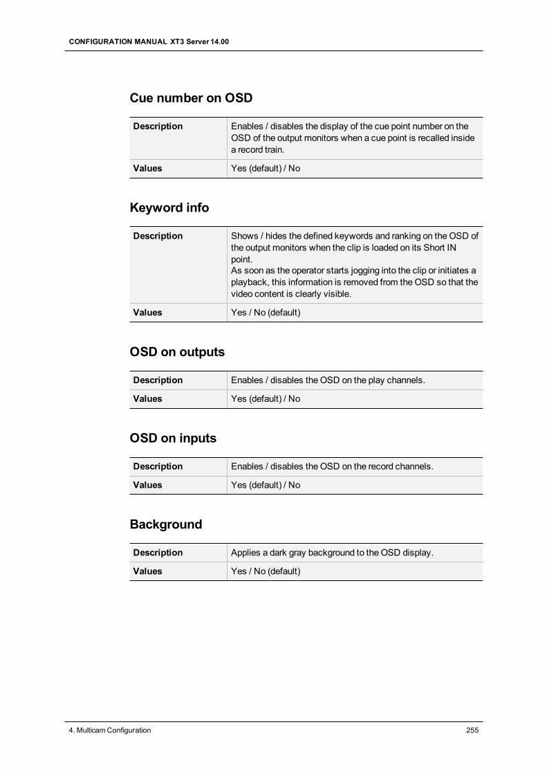
Cue number on OSD
Description Enables / disables the display of the cue point number on theOSD of the output monitors when a cue point is recalled insidea record train.
Values Yes (default) / No
Keyword info
Description Shows / hides the defined keywords and ranking on theOSD ofthe output monitors when the clip is loaded on its Short INpoint.As soon as the operator starts jogging into the clip or initiates aplayback, this information is removed from theOSD so that thevideo content is clearly visible.
Values Yes / No (default)
OSD on outputs
Description Enables / disables the OSD on the play channels.
Values Yes (default) / No
OSD on inputs
Description Enables / disables the OSD on the record channels.
Values Yes (default) / No
Background
Description Applies a dark gray background to the OSD display.
Values Yes / No (default)
CONFIGURATION MANUAL XT3 Server 14.00
4. MulticamConfiguration 255
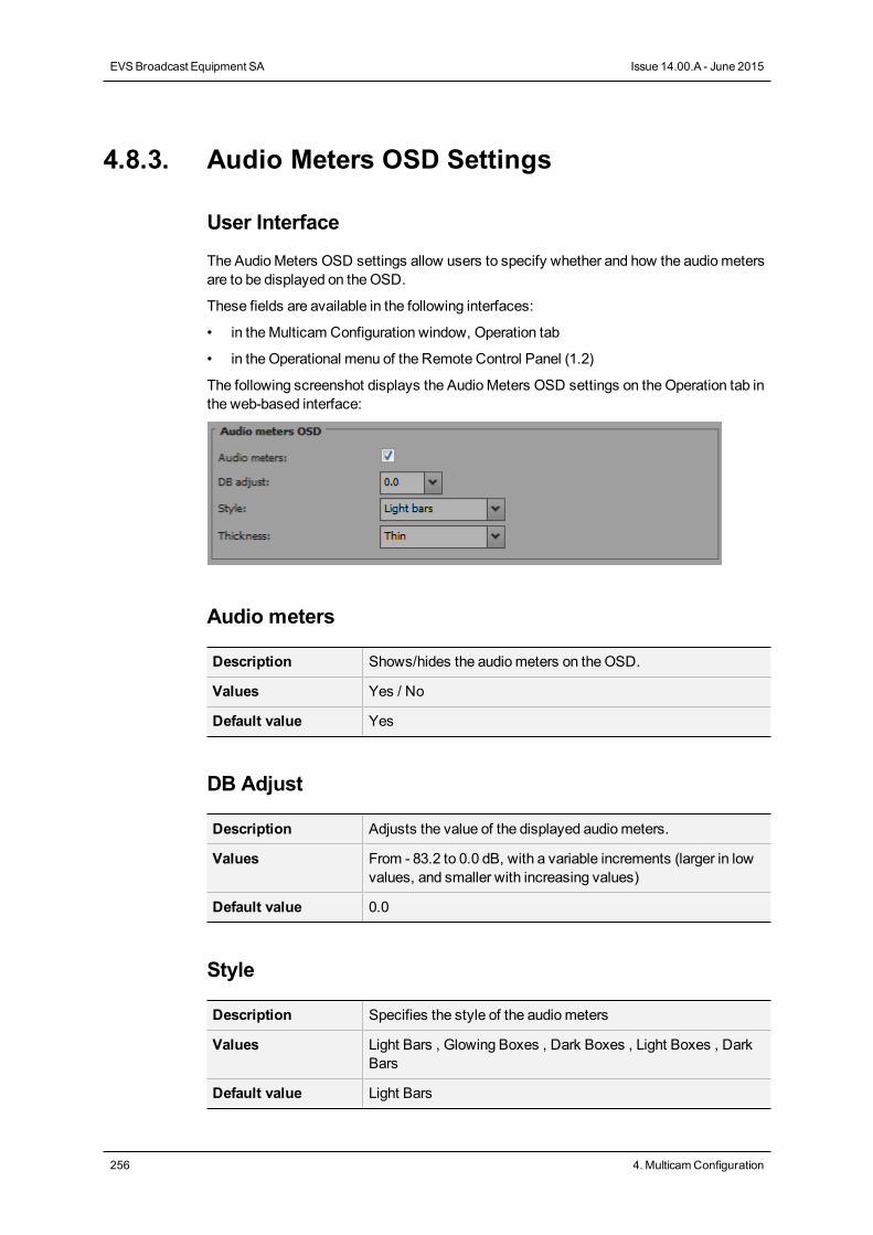
4.8.3. Audio Meters OSD Settings
User Interface
The AudioMeters OSD settings allow users to specify whether and how the audiometersare to be displayed on theOSD.
These fields are available in the following interfaces:
• in theMulticam Configuration window, Operation tab
• in the Operational menu of the Remote Control Panel (1.2)
The following screenshot displays the AudioMeters OSD settings on theOperation tab inthe web-based interface:
Audio meters
Description Shows/hides the audiometers on the OSD.
Values Yes / No
Default value Yes
DB Adjust
Description Adjusts the value of the displayed audiometers.
Values From - 83.2 to 0.0 dB, with a variable increments (larger in lowvalues, and smaller with increasing values)
Default value 0.0
Style
Description Specifies the style of the audiometers
Values Light Bars , Glowing Boxes , Dark Boxes , Light Boxes , DarkBars
Default value Light Bars
256 4. MulticamConfiguration
EVSBroadcast Equipment SA Issue 14.00.A - June 2015
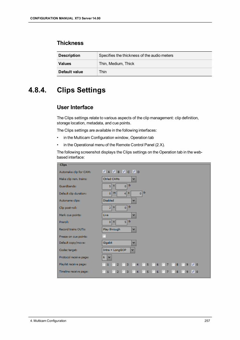
Thickness
Description Specifies the thickness of the audiometers
Values Thin, Medium, Thick
Default value Thin
4.8.4. Clips Settings
User Interface
The Clips settings relate to various aspects of the clip management: clip definition,storage location, metadata, and cue points.
The Clips settings are available in the following interfaces:
• in theMulticam Configuration window, Operation tab
• in the Operational menu of the Remote Control Panel (2.X).
The following screenshot displays the Clips settings on theOperation tab in the web-based interface:
CONFIGURATION MANUAL XT3 Server 14.00
4. MulticamConfiguration 257
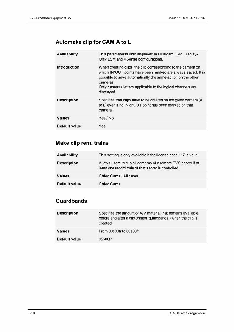
Automake clip for CAM A to L
Availability This parameter is only displayed inMulticam LSM, Replay-Only LSM and XSense configurations.
Introduction When creating clips, the clip corresponding to the camera onwhich IN/OUT points have beenmarked are always saved. It ispossible to save automatically the same action on the othercameras.Only cameras letters applicable to the logical channels aredisplayed.
Description Specifies that clips have to be created on the given camera (Ato L) even if no IN or OUT point has beenmarked on thatcamera.
Values Yes / No
Default value Yes
Make clip rem. trains
Availability This setting is only available if the license code 117 is valid.
Description Allows users to clip all cameras of a remote EVS server if atleast one record train of that server is controlled.
Values Ctrled Cams / All cams
Default value Ctrled Cams
Guardbands
Description Specifies the amount of A/V material that remains availablebefore and after a clip (called 'guardbands') when the clip iscreated.
Values From 00s00fr to 60s00fr
Default value 05s00fr
258 4. MulticamConfiguration
EVSBroadcast Equipment SA Issue 14.00.A - June 2015
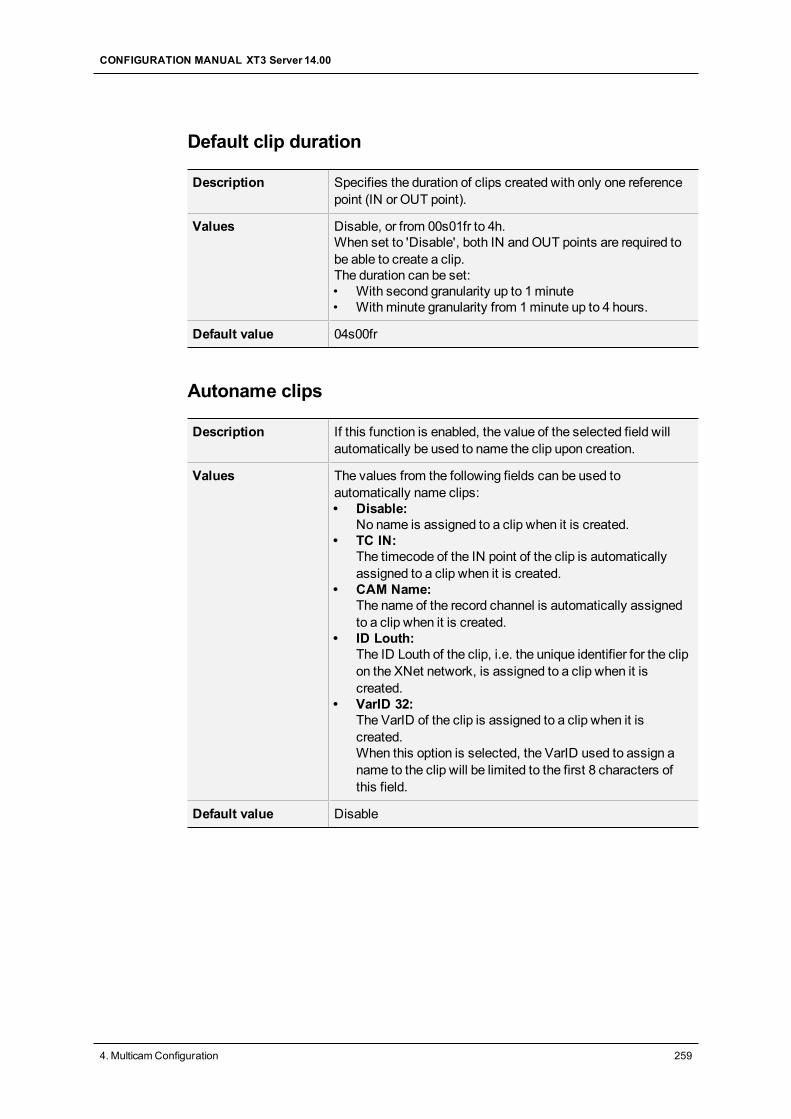
Default clip duration
Description Specifies the duration of clips created with only one referencepoint (IN or OUT point).
Values Disable, or from 00s01fr to 4h.When set to 'Disable', both IN andOUT points are required tobe able to create a clip.The duration can be set:• With second granularity up to 1minute• With minute granularity from 1minute up to 4 hours.
Default value 04s00fr
Autoname clips
Description If this function is enabled, the value of the selected field willautomatically be used to name the clip upon creation.
Values The values from the following fields can be used toautomatically name clips:• Disable:
No name is assigned to a clip when it is created.• TC IN:
The timecode of the IN point of the clip is automaticallyassigned to a clip when it is created.
• CAM Name:The name of the record channel is automatically assignedto a clip when it is created.
• ID Louth:The ID Louth of the clip, i.e. the unique identifier for the clipon the XNet network, is assigned to a clip when it iscreated.
• VarID 32:The VarID of the clip is assigned to a clip when it iscreated.When this option is selected, the VarID used to assign aname to the clip will be limited to the first 8 characters ofthis field.
Default value Disable
CONFIGURATION MANUAL XT3 Server 14.00
4. MulticamConfiguration 259
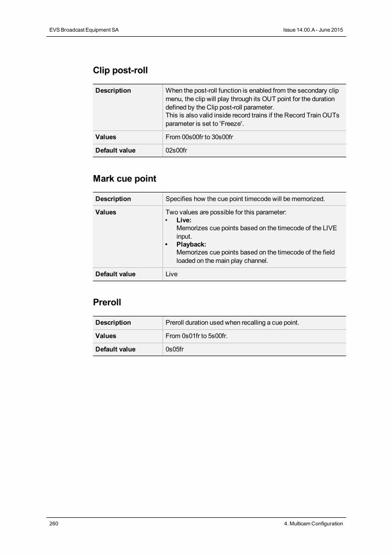
Clip post-roll
Description When the post-roll function is enabled from the secondary clipmenu, the clip will play through its OUT point for the durationdefined by the Clip post-roll parameter.This is also valid inside record trains if the Record Train OUTsparameter is set to 'Freeze'.
Values From 00s00fr to 30s00fr
Default value 02s00fr
Mark cue point
Description Specifies how the cue point timecode will bememorized.
Values Two values are possible for this parameter:• Live:
Memorizes cue points based on the timecode of the LIVEinput.
• Playback:Memorizes cue points based on the timecode of the fieldloaded on themain play channel.
Default value Live
Preroll
Description Preroll duration used when recalling a cue point.
Values From 0s01fr to 5s00fr.
Default value 0s05fr
260 4. MulticamConfiguration
EVSBroadcast Equipment SA Issue 14.00.A - June 2015
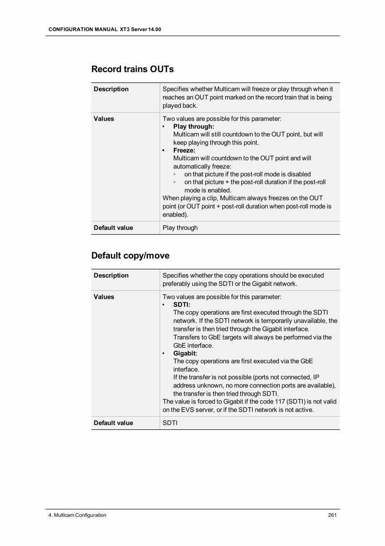
Record trains OUTs
Description Specifies whether Multicam will freeze or play through when itreaches anOUT point marked on the record train that is beingplayed back.
Values Two values are possible for this parameter:• Play through:
Multicam will still countdown to the OUT point, but willkeep playing through this point.
• Freeze:Multicam will countdown to the OUT point and willautomatically freeze:◦ on that picture if the post-roll mode is disabled◦ on that picture + the post-roll duration if the post-roll
mode is enabled.When playing a clip, Multicam always freezes on theOUTpoint (or OUT point + post-roll duration when post-roll mode isenabled).
Default value Play through
Default copy/move
Description Specifies whether the copy operations should be executedpreferably using the SDTI or the Gigabit network.
Values Two values are possible for this parameter:• SDTI:
The copy operations are first executed through the SDTInetwork. If the SDTI network is temporarily unavailable, thetransfer is then tried through theGigabit interface.Transfers to GbE targets will always be performed via theGbE interface.
• Gigabit:The copy operations are first executed via the GbEinterface.If the transfer is not possible (ports not connected, IPaddress unknown, nomore connection ports are available),the transfer is then tried through SDTI.
The value is forced to Gigabit if the code 117 (SDTI) is not validon the EVS server, or if the SDTI network is not active.
Default value SDTI
CONFIGURATION MANUAL XT3 Server 14.00
4. MulticamConfiguration 261
Freeze on cue points
Description Specifies whether Multicam will freeze or not when it reachesa cue point marked on the clip or the record train that is beingplayed back.The post-roll parameter is not taken into account for thisfunctionality.
Values • Yes:The playout freezes on the cue points when playing clips orrecord trains where cue points have been defined.
• No:The playout plays through the cue points when playingclips or record trains.
Default value No
Codec target
Description Specifies which essence(s) of the clip will be used in case ofclip copies to a distant server.
Values Two values are possible for this parameter:• Intra: Only the Intra essence of the clip is copied.• Intra + LongGOP: Both Intra and LongGOP essences of
the clip are copied.When the Proxy essence is active, it will always be copied.This value is therefore not selectable.
Default value Intra + LongGOP
Protocol Receive page
Description Specifies on which page the clips created by protocols arestored. When a page is full, clips are stored on the next page.Only clips created on this page (and the other protocol pages ifthe first page is full) are visible for protocols.
Values 1 to 10 (=0)
Default value 6
262 4. MulticamConfiguration
EVSBroadcast Equipment SA Issue 14.00.A - June 2015
Playlist Receive page
Introduction This setting is linked to the copy function that allows users toautomatically create a local copy of all network clips whencopying a local or network playlist. For details, refer to thedescription of the Playlist copy function in the Operationsmanual.
Availability The setting is only available if the license code 111 or 112 isvalid.
Description Specifies on which page(s) of your EVS server the clipsreceived when using the PLST+CLIPS copy functionmust bestored.Clip pages can be assigned simultaneously as PUSH andPLST Receive Pages.
Values 1 to 10 (=0)
Default value 0 (page 10)
Timeline Receive page
Description Specifies on which page(s) the clips automatically created intimelinemode as part of the timeline editing process are stored.
Values 1 to 10 (=0)
Default value 0 (page 10)
4.8.5. Playlist Settings
User Interface
The Playlist settings relate to various aspects of playlist management and effects.
These fields are available in the following interfaces:
• in theMulticam Configuration window, Operation tab
• in the Operational setupmenu of the Remote Control Panel (3.X)
CONFIGURATION MANUAL XT3 Server 14.00
4. MulticamConfiguration 263
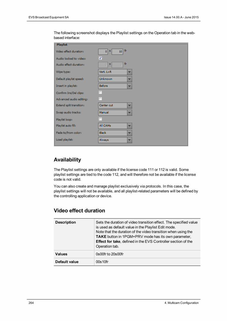
The following screenshot displays the Playlist settings on theOperation tab in the web-based interface:
Availability
The Playlist settings are only available if the license code 111 or 112 is valid. Someplaylist settings are tied to the code 112, and will therefore not be available if the licensecode is not valid.
You can also create andmanage playlist exclusively via protocols. In this case, theplaylist settings will not be available, and all playlist-related parameters will be defined bythe controlling application or device.
Video effect duration
Description Sets the duration of video transition effect. The specified valueis used as default value in the Playlist Edit mode.Note that the duration of the video transition when using theTAKE button in 1PGM+PRV mode has its own parameter,Effect for take, defined in the EVS Controller section of theOperation tab.
Values 0s00fr to 20s00fr
Default value 00s10fr
264 4. MulticamConfiguration
EVSBroadcast Equipment SA Issue 14.00.A - June 2015
Audio locked to video
Availability This setting is only available if the license code 112 is valid.
Description Specifies whether you will be able to define different durationsfor the audio and video transitions inside a playlist when theAdvanced Audio Editing parameter is enabled.This setting is irrelevant if the Advanced Audio Editingparameter is disabled.
Values The possible values are:• Yes: The duration of video and audio transitions in a playlist
cannot be different.• No: The duration of the video and audio transitions in a
playlist can be different.If the license code 112 for advanced audio editing is not valid,the parameter value is forced to 'Yes'.
Default value Yes
Audio effect duration
Availability This setting is only available if the license code 112 is valid.This setting is only available when theAudio locked to videosetting is set toNo.
Description Sets the duration of the audio transition effect when:• the Advanced Audio Editing setting is enabled.• the Audio locked to video setting is set to 'No'.The specified value is used as default value in Playlist Editmode.If the Advanced Audio Editing is disabled, this setting is notrelevant since the video and audio transitions will always havethe same duration, based on the Video Effect Duration.
Values 0s00fr to 20s00fr
Default value 0s00fr
Wipe type
Description Specifies the vertical wipe effects from Left to Right or fromRight to Left.
Values Vert. L>R / Vert. R>L
Default value Vert. L > R
CONFIGURATION MANUAL XT3 Server 14.00
4. MulticamConfiguration 265
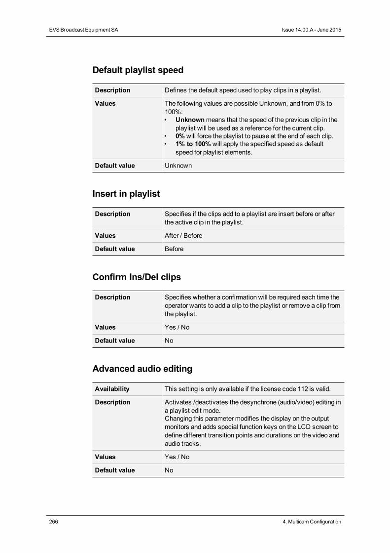
Default playlist speed
Description Defines the default speed used to play clips in a playlist.
Values The following values are possible Unknown, and from 0% to100%:• Unknownmeans that the speed of the previous clip in the
playlist will be used as a reference for the current clip.• 0% will force the playlist to pause at the end of each clip.• 1% to 100% will apply the specified speed as default
speed for playlist elements.
Default value Unknown
Insert in playlist
Description Specifies if the clips add to a playlist are insert before or afterthe active clip in the playlist.
Values After / Before
Default value Before
Confirm Ins/Del clips
Description Specifies whether a confirmation will be required each time theoperator wants to add a clip to the playlist or remove a clip fromthe playlist.
Values Yes / No
Default value No
Advanced audio editing
Availability This setting is only available if the license code 112 is valid.
Description Activates /deactivates the desynchrone (audio/video) editing ina playlist edit mode.Changing this parameter modifies the display on the outputmonitors and adds special function keys on the LCD screen todefine different transition points and durations on the video andaudio tracks.
Values Yes / No
Default value No
266 4. MulticamConfiguration
EVSBroadcast Equipment SA Issue 14.00.A - June 2015
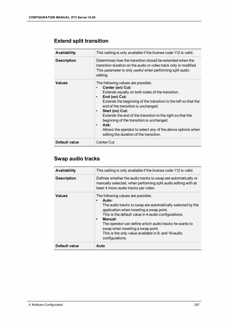
Extend split transition
Availability This setting is only available if the license code 112 is valid.
Description Determines how the transition should be extended when thetransition duration on the audio or video track only is modified.This parameter is only useful when performing split audioediting.
Values The following values are possible:• Center (on) Cut:
Extends equally on both sides of the transition.• End (on) Cut:
Extends the beginning of the transition to the left so that theend of the transition is unchanged.
• Start (on) Cut:Extends the end of the transition to the right so that thebeginning of the transition is unchanged.
• Ask:Allows the operator to select any of the above options whenediting the duration of the transition.
Default value Center Cut
Swap audio tracks
Availability This setting is only available if the license code 112 is valid.
Description Defines whether the audio tracks to swap are automatically ormanually selected, when performing split audio editing with atleast 4mono audio tracks per video.
Values The following values are possible:• Auto:
The audio tracks to swap are automatically selected by theapplication when inserting a swap point.This is the default value in 4-audio configurations.
• Manual:The operator can define which audio tracks he wants toswap when inserting a swap point.This is the only value available in 8- and 16-audioconfigurations.
Default value Auto
CONFIGURATION MANUAL XT3 Server 14.00
4. MulticamConfiguration 267
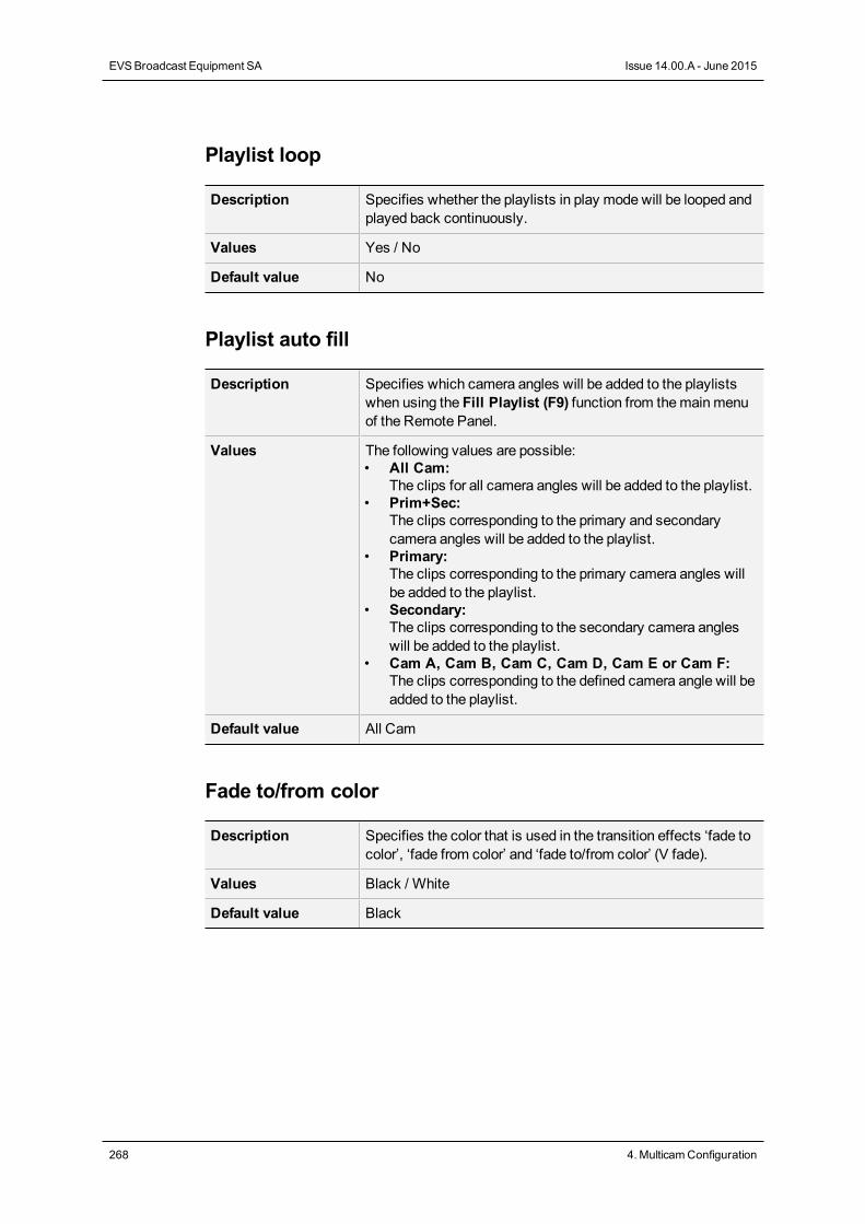
Playlist loop
Description Specifies whether the playlists in play mode will be looped andplayed back continuously.
Values Yes / No
Default value No
Playlist auto fill
Description Specifies which camera angles will be added to the playlistswhen using the Fill Playlist (F9) function from themainmenuof the Remote Panel.
Values The following values are possible:• All Cam:
The clips for all camera angles will be added to the playlist.• Prim+Sec:
The clips corresponding to the primary and secondarycamera angles will be added to the playlist.
• Primary:The clips corresponding to the primary camera angles willbe added to the playlist.
• Secondary:The clips corresponding to the secondary camera angleswill be added to the playlist.
• Cam A, Cam B, Cam C, Cam D, Cam E or Cam F:The clips corresponding to the defined camera angle will beadded to the playlist.
Default value All Cam
Fade to/from color
Description Specifies the color that is used in the transition effects ‘fade tocolor’, ‘fade from color’ and ‘fade to/from color’ (V fade).
Values Black / White
Default value Black
268 4. MulticamConfiguration
EVSBroadcast Equipment SA Issue 14.00.A - June 2015
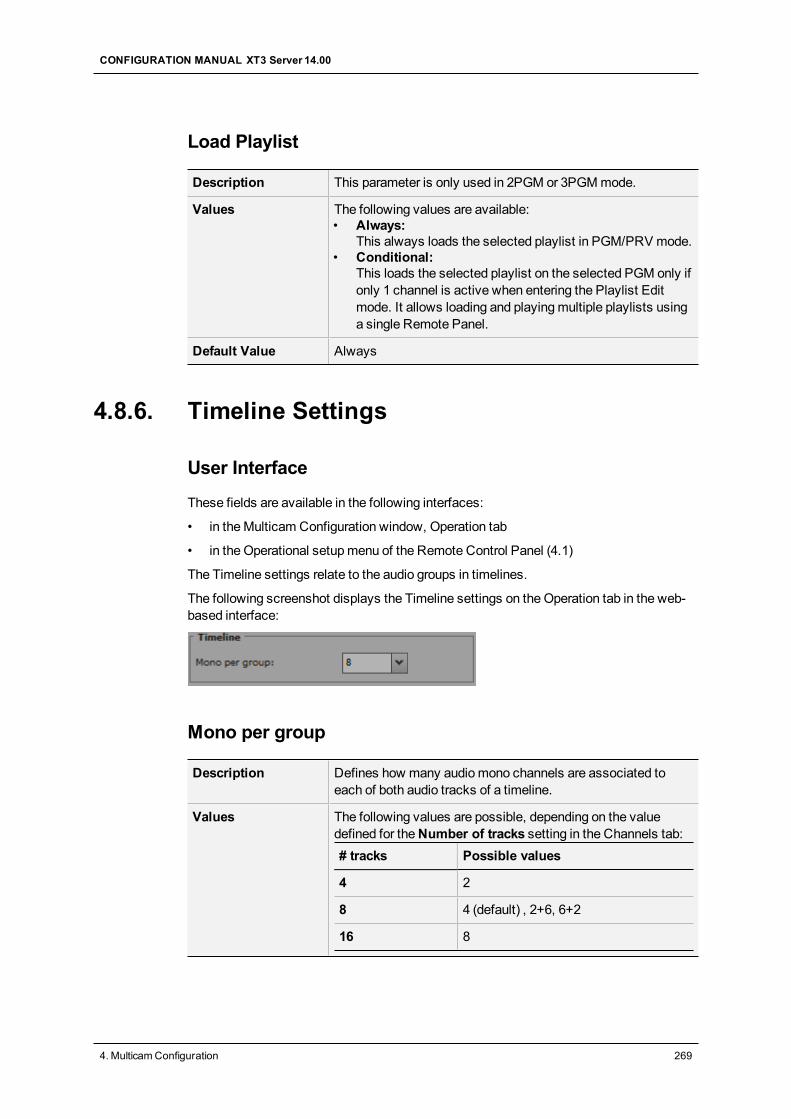
Load Playlist
Description This parameter is only used in 2PGM or 3PGMmode.
Values The following values are available:• Always:
This always loads the selected playlist in PGM/PRV mode.• Conditional:
This loads the selected playlist on the selected PGM only ifonly 1 channel is active when entering the Playlist Editmode. It allows loading and playingmultiple playlists usinga single Remote Panel.
Default Value Always
4.8.6. Timeline Settings
User Interface
These fields are available in the following interfaces:
• in theMulticam Configuration window, Operation tab
• in the Operational setupmenu of the Remote Control Panel (4.1)
The Timeline settings relate to the audio groups in timelines.
The following screenshot displays the Timeline settings on theOperation tab in the web-based interface:
Mono per group
Description Defines how many audiomono channels are associated toeach of both audio tracks of a timeline.
Values The following values are possible, depending on the valuedefined for theNumber of tracks setting in the Channels tab:# tracks Possible values
4 2
8 4 (default) , 2+6, 6+2
16 8
CONFIGURATION MANUAL XT3 Server 14.00
4. MulticamConfiguration 269
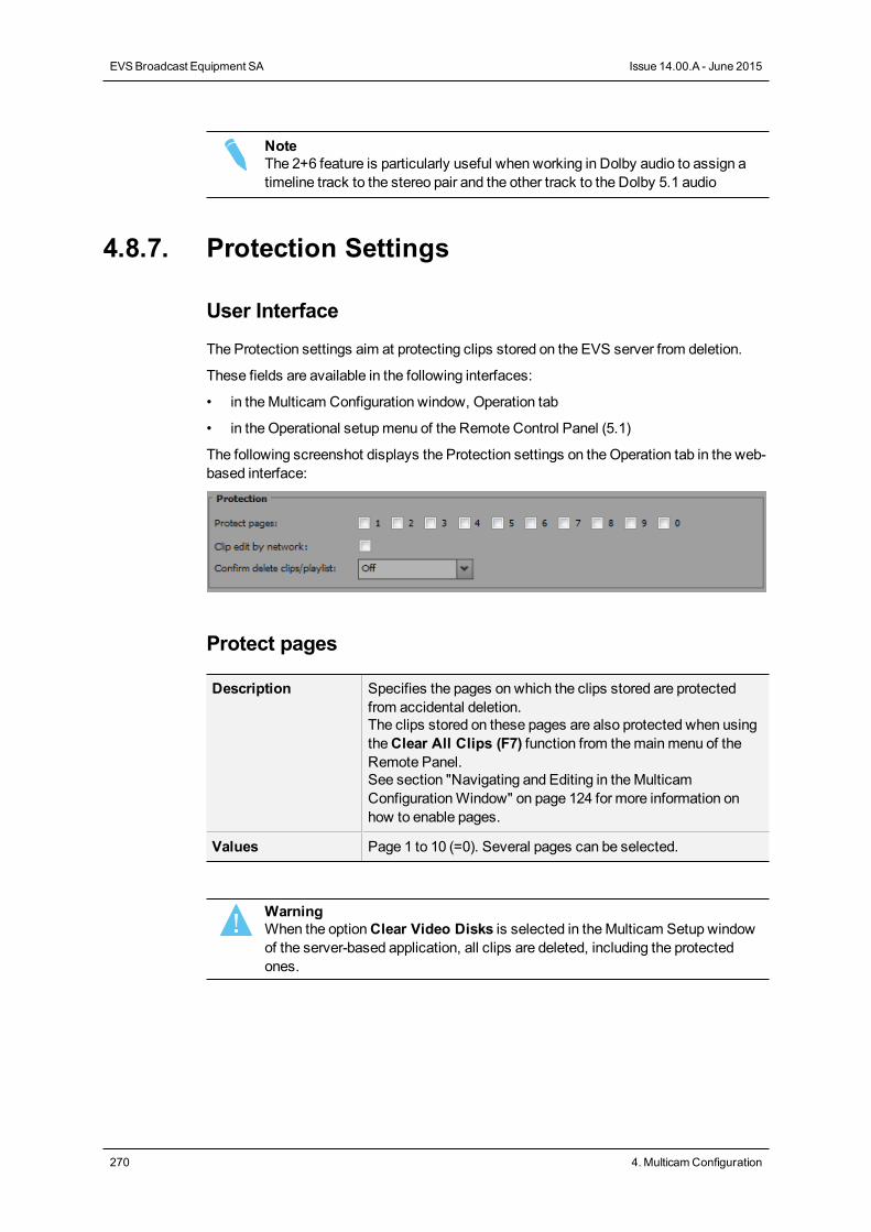
NoteThe 2+6 feature is particularly useful when working in Dolby audio to assign atimeline track to the stereo pair and the other track to the Dolby 5.1 audio
4.8.7. Protection Settings
User Interface
The Protection settings aim at protecting clips stored on the EVS server from deletion.
These fields are available in the following interfaces:
• in theMulticam Configuration window, Operation tab
• in the Operational setupmenu of the Remote Control Panel (5.1)
The following screenshot displays the Protection settings on theOperation tab in the web-based interface:
Protect pages
Description Specifies the pages on which the clips stored are protectedfrom accidental deletion.The clips stored on these pages are also protected when usingtheClear All Clips (F7) function from themainmenu of theRemote Panel.See section "Navigating and Editing in theMulticamConfigurationWindow" on page 124 for more information onhow to enable pages.
Values Page 1 to 10 (=0). Several pages can be selected.
WarningWhen the optionClear Video Disks is selected in theMulticam Setup windowof the server-based application, all clips are deleted, including the protectedones.
270 4. MulticamConfiguration
EVSBroadcast Equipment SA Issue 14.00.A - June 2015
Clip edit by network
Availability This setting is only available if the license code 117 is valid.
Description Allows users to edit clips on the whole SDTI network.
Values The following values are possible:• Yes:
Other users on the network can trim, rename, delete, etc.your clips, or modify the keywords and ranking assigned toyour clips.
• No:Only the local operators canmodify or delete clips on theserver and edit their metadata.
Default value No
Confirm delete clips/playlists
Description Enables a confirmation request when users delete clips,playlists or in both situations.
Values The following values are possible:• Off:
Clips and playlists are immediately deleted.• Clips:
A confirmation is required for a clip deletion, but not for aplaylist deletion.
• Playlists:A confirmation is required for a playlist deletion, but not fora clip deletion.
• Clips & Playlists:A confirmation is required both for a playlist deletion, andfor a clip deletion.
Default Values Off
NoteThis parameter does not apply to theClear Video Disks command, available intheMulticam Setup window of the server-based application, which already hasits own confirmationmessage.
CONFIGURATION MANUAL XT3 Server 14.00
4. MulticamConfiguration 271
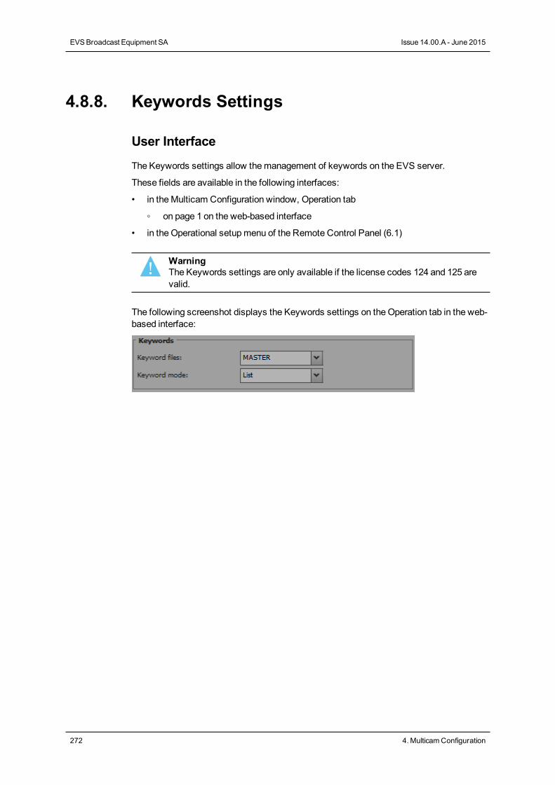
4.8.8. Keywords Settings
User Interface
The Keywords settings allow themanagement of keywords on the EVS server.
These fields are available in the following interfaces:
• in theMulticam Configuration window, Operation tab
◦ on page 1 on the web-based interface
• in the Operational setupmenu of the Remote Control Panel (6.1)
WarningThe Keywords settings are only available if the license codes 124 and 125 arevalid.
The following screenshot displays the Keywords settings on theOperation tab in the web-based interface:
272 4. MulticamConfiguration
EVSBroadcast Equipment SA Issue 14.00.A - June 2015
Keyword files
Description Specifies the keywords file that can be used to assignkeywords to clips or to search the clips database.
Values The following values are possible:• -------- :
No keywords file is selected, and the keyword assignmentand related search functions are not available.
• SERVER:The keywords file sent by the active EVS server to allsystems on the SDTI network will be used. This value isonly available if the SDTI network is used.
• <Keywords file name>:◦ Other file names will appear if keywords files (files with
a .KWD extension) have been loaded in theC:\LSMCE\DATA\KWD directory of the system.
◦ Keyword files can be imported using the Import/ExportKeyword Files function in theMulticam Setup window.See section "Importing and Exporting Keyword Files"on page 46 for details about keyword import/exportfunction,
◦ See the "KeywordManagement" section in theMulticam operational manual for details about thekeywords file format and keywords-related functions,
Default Values -------- (keywords file not selected)
Keyword mode
Description Specifies the keyword assignment/searchmode on the EVSRemote Panel.
Values The following values are possible:• List:
It will display the keywords by groups of 8 on the LCD ofthe Remote Panel and the operator can select them withthe corresponding F_ key.
• Numeric:It doesn’t display the keywords list on the LCD, but allowsthe operator to enter directly the keyword ID using the F_keys.The Numeric mode is faster when the operator knows theposition of the keywords inside the keywords file, eitherfrommemory, using the VGA keyword screens, or using aprint of the keywords list.
Default Values List
CONFIGURATION MANUAL XT3 Server 14.00
4. MulticamConfiguration 273
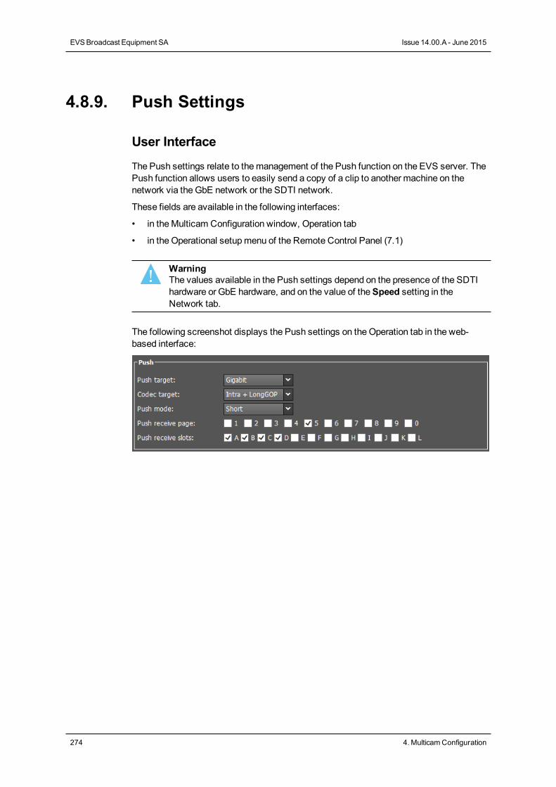
4.8.9. Push Settings
User Interface
The Push settings relate to themanagement of the Push function on the EVS server. ThePush function allows users to easily send a copy of a clip to another machine on thenetwork via the GbE network or the SDTI network.
These fields are available in the following interfaces:
• in theMulticam Configuration window, Operation tab
• in the Operational setupmenu of the Remote Control Panel (7.1)
WarningThe values available in the Push settings depend on the presence of the SDTIhardware or GbE hardware, and on the value of theSpeed setting in theNetwork tab.
The following screenshot displays the Push settings on theOperation tab in the web-based interface:
274 4. MulticamConfiguration
EVSBroadcast Equipment SA Issue 14.00.A - June 2015
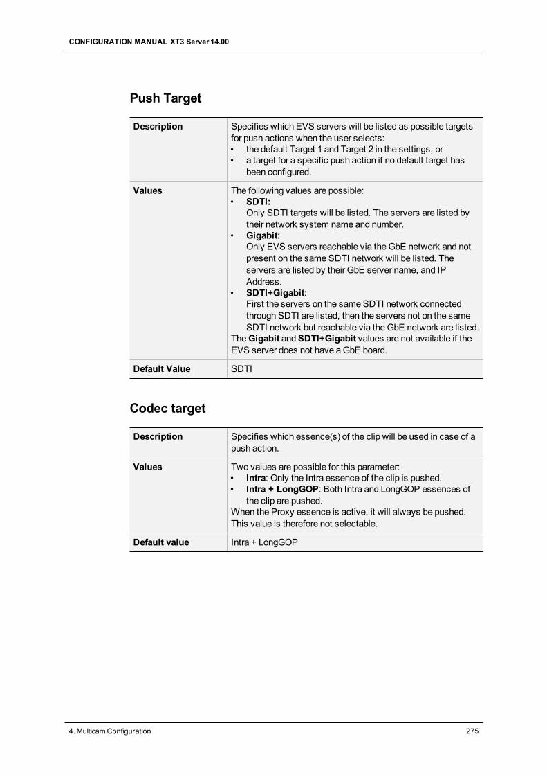
Push Target
Description Specifies which EVS servers will be listed as possible targetsfor push actions when the user selects:• the default Target 1 and Target 2 in the settings, or• a target for a specific push action if no default target has
been configured.
Values The following values are possible:• SDTI:
Only SDTI targets will be listed. The servers are listed bytheir network system name and number.
• Gigabit:Only EVS servers reachable via the GbE network and notpresent on the same SDTI network will be listed. Theservers are listed by their GbE server name, and IPAddress.
• SDTI+Gigabit:First the servers on the same SDTI network connectedthrough SDTI are listed, then the servers not on the sameSDTI network but reachable via the GbE network are listed.
TheGigabit andSDTI+Gigabit values are not available if theEVS server does not have aGbE board.
Default Value SDTI
Codec target
Description Specifies which essence(s) of the clip will be used in case of apush action.
Values Two values are possible for this parameter:• Intra: Only the Intra essence of the clip is pushed.• Intra + LongGOP: Both Intra and LongGOP essences of
the clip are pushed.When the Proxy essence is active, it will always be pushed.This value is therefore not selectable.
Default value Intra + LongGOP
CONFIGURATION MANUAL XT3 Server 14.00
4. MulticamConfiguration 275
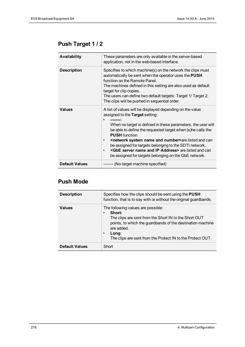
Push Target 1 / 2
Availability These parameters are only available in the server-basedapplication, not in the web-based interface.
Description Specifies to whichmachine(s) on the network the clips mustautomatically be sent when the operator uses thePUSHfunction on the Remote Panel.Themachines defined in this setting are also used as defaulttarget for clip copies.The users can define two default targets: Target 1/ Target 2.The clips will be pushed in sequential order.
Values A list of values will be displayed depending on the valueassigned to the Target setting:• --------:
When no target is defined in these parameters, the user willbe able to define the requested target when (s)he calls thePUSH function.
• <network system name and number>are listed and canbe assigned for targets belonging to the SDTI network.
• <GbE server name and IP Address> are listed and canbe assigned for targets belonging on theGbE network.
Default Values -------- (No target machine specified)
Push Mode
Description Specifies how the clips should be sent using thePUSHfunction, that is to say with or without the original guardbands.
Values The following values are possible:• Short:
The clips are sent from the Short IN to the Short OUTpoints, to which the guardbands of the destinationmachineare added.
• Long:The clips are sent from the Protect IN to the Protect OUT.
Default Values Short
276 4. MulticamConfiguration
EVSBroadcast Equipment SA Issue 14.00.A - June 2015
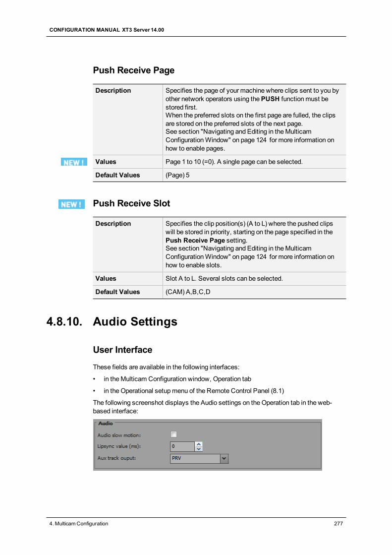
Push Receive Page
Description Specifies the page of your machine where clips sent to you byother network operators using thePUSH functionmust bestored first.When the preferred slots on the first page are fulled, the clipsare stored on the preferred slots of the next page.See section "Navigating and Editing in theMulticamConfigurationWindow" on page 124 for more information onhow to enable pages.
Values Page 1 to 10 (=0). A single page can be selected.
Default Values (Page) 5
Push Receive Slot
Description Specifies the clip position(s) (A to L) where the pushed clipswill be stored in priority, starting on the page specified in thePush Receive Page setting.See section "Navigating and Editing in theMulticamConfigurationWindow" on page 124 for more information onhow to enable slots.
Values Slot A to L. Several slots can be selected.
Default Values (CAM) A,B,C,D
4.8.10. Audio Settings
User Interface
These fields are available in the following interfaces:
• in theMulticam Configuration window, Operation tab
• in the Operational setupmenu of the Remote Control Panel (8.1)
The following screenshot displays the Audio settings on theOperation tab in the web-based interface:
CONFIGURATION MANUAL XT3 Server 14.00
4. MulticamConfiguration 277
Audio slow motion
Description Allows users to play back or mute the audio track when theplaying speed is different than 100%.
Values The following values are possible:• Yes: The audio track is not muted during the playback.• No: The audio track is muted during the playback.
Default value No
Lipsync value (ms)
Description Specifies the delay (in ms) between video and audio signals:• A positive valuemeans video is ahead of audio.• A negative valuemeans audio ahead of video.
Values The following values are possible:• Range for PAL: from -41,458ms to 14,708ms →848 to
3544 samples, 0ms →2838 samples• Range for NTSC: from -34,625 to 12,125ms →688 to 2932
(samples), 0 ms →2350 samples
Default value 0ms
NoteThis adjustment is done during the record process. A new Lipsync value willapply for the next recorded pictures only.
278 4. MulticamConfiguration
EVSBroadcast Equipment SA Issue 14.00.A - June 2015
Aux track output
Description Specifies to which audio outputs the auxiliary track of theplaylist will be played out.
Values The following values are possible:• PRV:
The auxiliary track will use the audio outputs normallyassigned to the PRV channel. If no PRV channel isavailable, the Aux Track will not be assigned to any audiooutput.
• PRV&7-8/15-16:The auxiliary track will use the audio outputs normallyassigned to the PRV channel if there is one, plus all theaudio outputs from 7-8/15-16 that have not yet beenassigned to another channel. Use this option if you need anauxiliary track without PRV channel available.
• PGM:The auxiliary track will use the audio outputs normallyassigned to the PGM channel.
Default value PRV
4.8.11. EVS Controller Settings
Introduction
The EVS Controller settings gather:
◦ Settings related to the behavior of the keys, lever or jog of the Remote Panel.
◦ Settings associated to the EVS server itself.
WarningMost of the settings are only available or applicable with base configurationsassociated to the use of an EVS Remote Panel (LSM Remote, XSenseRemote).
CONFIGURATION MANUAL XT3 Server 14.00
4. MulticamConfiguration 279
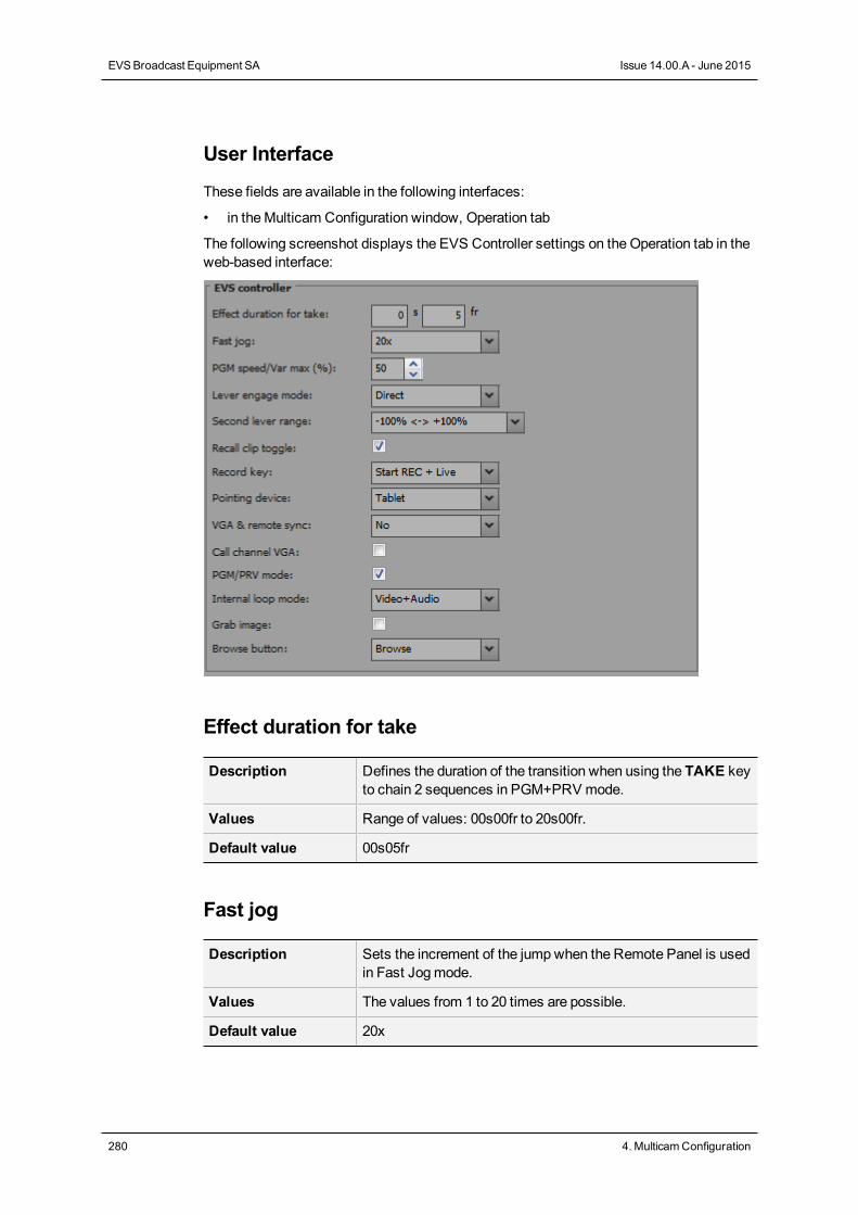
User Interface
These fields are available in the following interfaces:
• in theMulticam Configuration window, Operation tab
The following screenshot displays the EVS Controller settings on theOperation tab in theweb-based interface:
Effect duration for take
Description Defines the duration of the transition when using the TAKE keyto chain 2 sequences in PGM+PRV mode.
Values Range of values: 00s00fr to 20s00fr.
Default value 00s05fr
Fast jog
Description Sets the increment of the jumpwhen the Remote Panel is usedin Fast Jogmode.
Values The values from 1 to 20 times are possible.
Default value 20x
280 4. MulticamConfiguration
EVSBroadcast Equipment SA Issue 14.00.A - June 2015
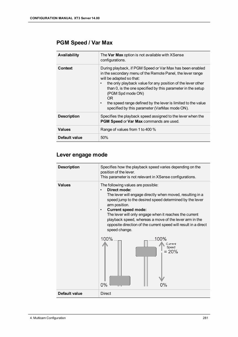
PGM Speed / Var Max
Availability TheVar Max option is not available with XSenseconfigurations.
Context During playback, if PGM Speed or Var Max has been enabledin the secondary menu of the Remote Panel, the lever rangewill be adapted so that:• the only playback value for any position of the lever other
than 0, is the one specified by this parameter in the setup(PGM SpdmodeON)OR
• the speed range defined by the lever is limited to the valuespecified by this parameter (VarMax modeON).
Description Specifies the playback speed assigned to the lever when thePGM Speed orVar Max commands are used.
Values Range of values from 1 to 400%
Default value 50%
Lever engage mode
Description Specifies how the playback speed varies depending on theposition of the lever.This parameter is not relevant in XSense configurations.
Values The following values are possible:• Direct mode:
The lever will engage directly whenmoved, resulting in aspeed jump to the desired speed determined by the leverarm position.
• Current speed mode:The lever will only engage when it reaches the currentplayback speed, whereas amove of the lever arm in theopposite direction of the current speed will result in a directspeed change.
Default value Direct
CONFIGURATION MANUAL XT3 Server 14.00
4. MulticamConfiguration 281
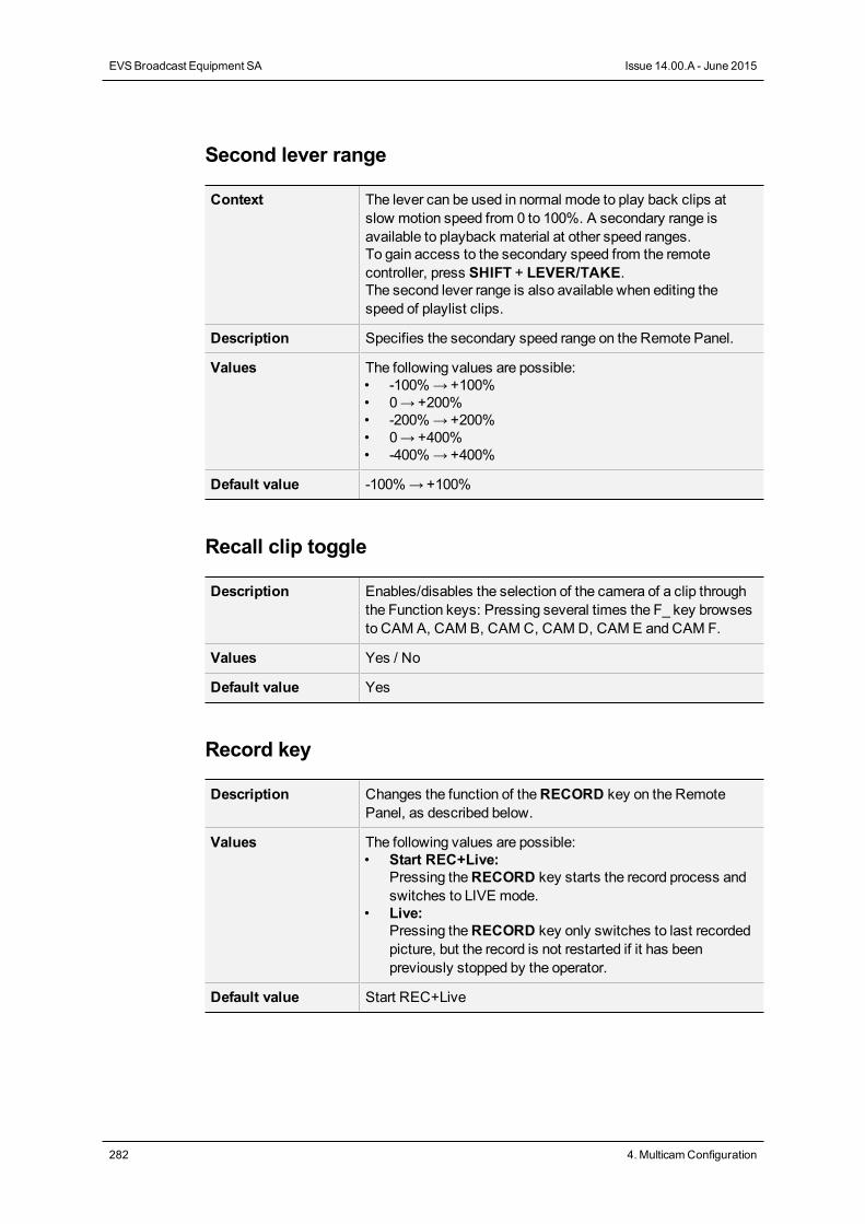
Second lever range
Context The lever can be used in normal mode to play back clips atslow motion speed from 0 to 100%. A secondary range isavailable to playback material at other speed ranges.To gain access to the secondary speed from the remotecontroller, press SHIFT + LEVER/TAKE.The second lever range is also available when editing thespeed of playlist clips.
Description Specifies the secondary speed range on the Remote Panel.
Values The following values are possible:• -100%→+100%• 0→+200%• -200%→+200%• 0→+400%• -400%→+400%
Default value -100%→+100%
Recall clip toggle
Description Enables/disables the selection of the camera of a clip throughthe Function keys: Pressing several times the F_ key browsesto CAM A, CAM B, CAMC, CAMD, CAM E and CAM F.
Values Yes / No
Default value Yes
Record key
Description Changes the function of theRECORD key on the RemotePanel, as described below.
Values The following values are possible:• Start REC+Live:
Pressing theRECORD key starts the record process andswitches to LIVE mode.
• Live:Pressing theRECORD key only switches to last recordedpicture, but the record is not restarted if it has beenpreviously stopped by the operator.
Default value Start REC+Live
282 4. MulticamConfiguration
EVSBroadcast Equipment SA Issue 14.00.A - June 2015
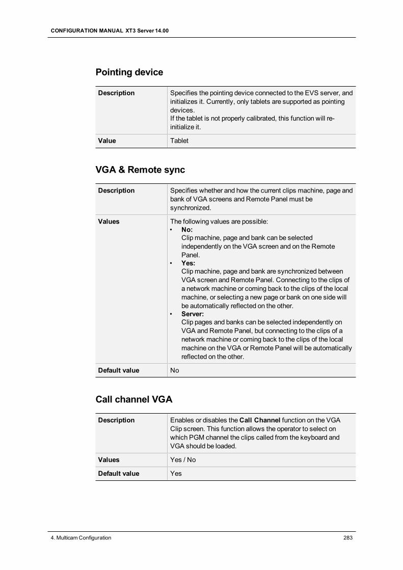
Pointing device
Description Specifies the pointing device connected to the EVS server, andinitializes it. Currently, only tablets are supported as pointingdevices.If the tablet is not properly calibrated, this function will re-initialize it.
Value Tablet
VGA & Remote sync
Description Specifies whether and how the current clips machine, page andbank of VGA screens and Remote Panel must besynchronized.
Values The following values are possible:• No:
Clip machine, page and bank can be selectedindependently on the VGA screen and on the RemotePanel.
• Yes:Clip machine, page and bank are synchronized betweenVGA screen and Remote Panel. Connecting to the clips ofa network machine or coming back to the clips of the localmachine, or selecting a new page or bank on one side willbe automatically reflected on the other.
• Server:Clip pages and banks can be selected independently onVGA and Remote Panel, but connecting to the clips of anetwork machine or coming back to the clips of the localmachine on the VGA or Remote Panel will be automaticallyreflected on the other.
Default value No
Call channel VGA
Description Enables or disables theCall Channel function on the VGAClip screen. This function allows the operator to select onwhich PGM channel the clips called from the keyboard andVGA should be loaded.
Values Yes / No
Default value Yes
CONFIGURATION MANUAL XT3 Server 14.00
4. MulticamConfiguration 283
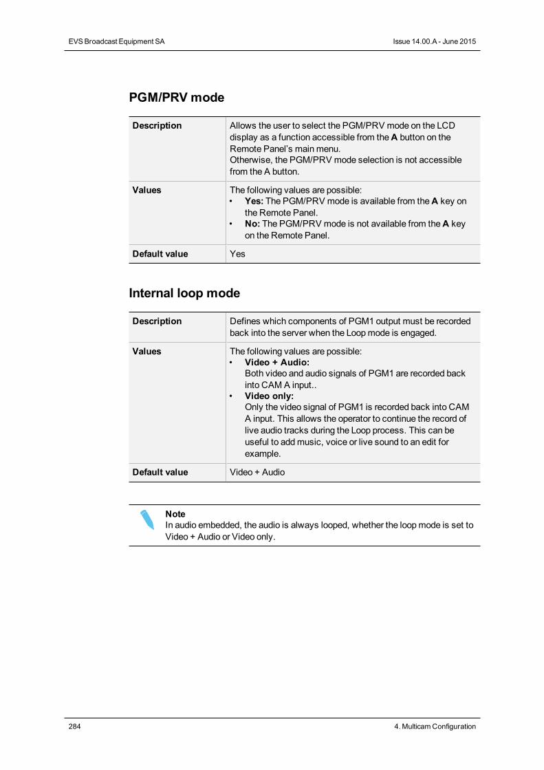
PGM/PRV mode
Description Allows the user to select the PGM/PRV mode on the LCDdisplay as a function accessible from theA button on theRemote Panel’s mainmenu.Otherwise, the PGM/PRV mode selection is not accessiblefrom the A button.
Values The following values are possible:• Yes: The PGM/PRV mode is available from theA key on
the Remote Panel.• No: The PGM/PRV mode is not available from theA key
on the Remote Panel.
Default value Yes
Internal loop mode
Description Defines which components of PGM1 output must be recordedback into the server when the Loopmode is engaged.
Values The following values are possible:• Video + Audio:
Both video and audio signals of PGM1 are recorded backinto CAM A input..
• Video only:Only the video signal of PGM1 is recorded back into CAMA input. This allows the operator to continue the record oflive audio tracks during the Loop process. This can beuseful to addmusic, voice or live sound to an edit forexample.
Default value Video + Audio
NoteIn audio embedded, the audio is always looped, whether the loopmode is set toVideo + Audio or Video only.
284 4. MulticamConfiguration
EVSBroadcast Equipment SA Issue 14.00.A - June 2015
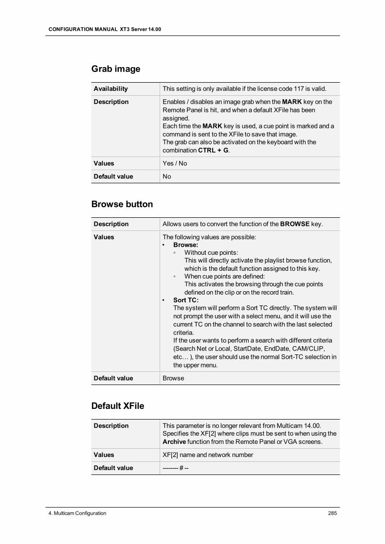
Grab image
Availability This setting is only available if the license code 117 is valid.
Description Enables / disables an image grab when theMARK key on theRemote Panel is hit, and when a default XFile has beenassigned.Each time theMARK key is used, a cue point is marked and acommand is sent to the XFile to save that image.The grab can also be activated on the keyboard with thecombinationCTRL + G.
Values Yes / No
Default value No
Browse button
Description Allows users to convert the function of theBROWSE key.
Values The following values are possible:• Browse:
◦ Without cue points:This will directly activate the playlist browse function,which is the default function assigned to this key.
◦ When cue points are defined:This activates the browsing through the cue pointsdefined on the clip or on the record train.
• Sort TC:The system will perform a Sort TC directly. The system willnot prompt the user with a select menu, and it will use thecurrent TC on the channel to search with the last selectedcriteria.If the user wants to perform a search with different criteria(Search Net or Local, StartDate, EndDate, CAM/CLIP,etc… ), the user should use the normal Sort-TC selection inthe upper menu.
Default value Browse
Default XFile
Description This parameter is no longer relevant fromMulticam 14.00.Specifies the XF[2] where clips must be sent to when using theArchive function from the Remote Panel or VGA screens.
Values XF[2] name and network number
Default value -------- # --
CONFIGURATION MANUAL XT3 Server 14.00
4. MulticamConfiguration 285
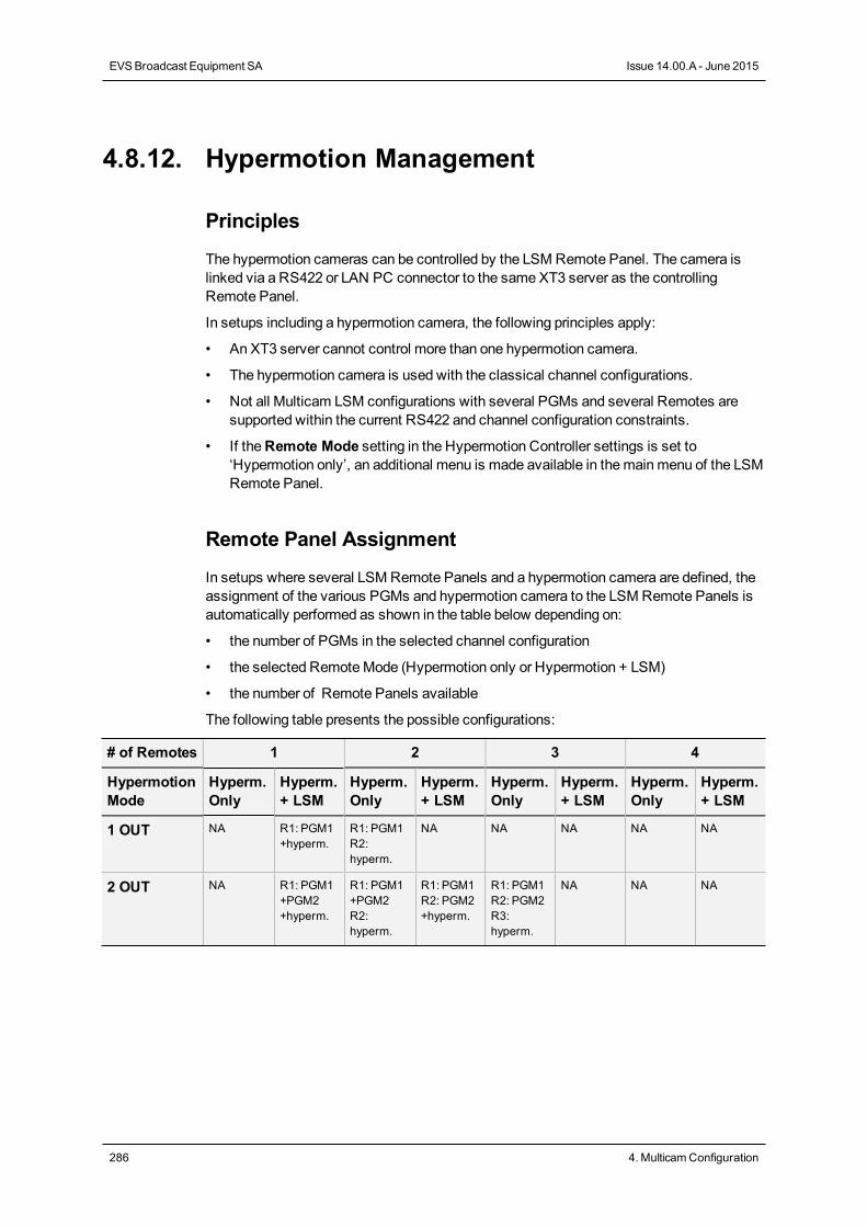
4.8.12. Hypermotion Management
Principles
The hypermotion cameras can be controlled by the LSM Remote Panel. The camera islinked via a RS422 or LAN PC connector to the same XT3 server as the controllingRemote Panel.
In setups including a hypermotion camera, the following principles apply:
• An XT3 server cannot control more than one hypermotion camera.
• The hypermotion camera is used with the classical channel configurations.
• Not all Multicam LSM configurations with several PGMs and several Remotes aresupported within the current RS422 and channel configuration constraints.
• If theRemote Mode setting in the Hypermotion Controller settings is set to‘Hypermotion only’, an additional menu is made available in themainmenu of the LSMRemote Panel.
Remote Panel Assignment
In setups where several LSM Remote Panels and a hypermotion camera are defined, theassignment of the various PGMs and hypermotion camera to the LSM Remote Panels isautomatically performed as shown in the table below depending on:
• the number of PGMs in the selected channel configuration
• the selected RemoteMode (Hypermotion only or Hypermotion + LSM)
• the number of Remote Panels available
The following table presents the possible configurations:
# of Remotes 1 2 3 4
HypermotionMode
Hyperm.Only
Hyperm.+ LSM
Hyperm.Only
Hyperm.+ LSM
Hyperm.Only
Hyperm.+ LSM
Hyperm.Only
Hyperm.+ LSM
1 OUT NA R1: PGM1+hyperm.
R1: PGM1R2:hyperm.
NA NA NA NA NA
2 OUT NA R1: PGM1+PGM2+hyperm.
R1: PGM1+PGM2R2:hyperm.
R1: PGM1R2: PGM2+hyperm.
R1: PGM1R2: PGM2R3:hyperm.
NA NA NA
286 4. MulticamConfiguration
EVSBroadcast Equipment SA Issue 14.00.A - June 2015
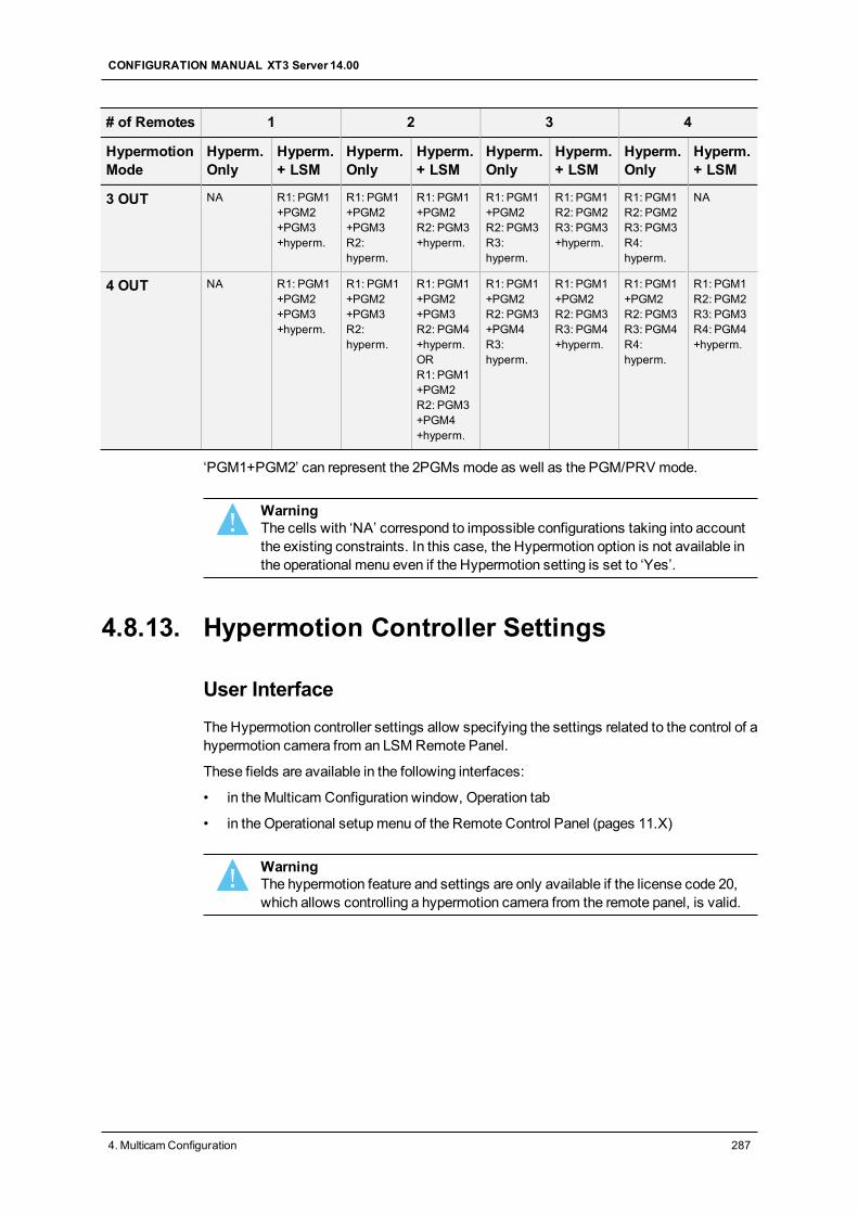
# of Remotes 1 2 3 4
HypermotionMode
Hyperm.Only
Hyperm.+ LSM
Hyperm.Only
Hyperm.+ LSM
Hyperm.Only
Hyperm.+ LSM
Hyperm.Only
Hyperm.+ LSM
3 OUT NA R1: PGM1+PGM2+PGM3+hyperm.
R1: PGM1+PGM2+PGM3R2:hyperm.
R1: PGM1+PGM2R2: PGM3+hyperm.
R1: PGM1+PGM2R2: PGM3R3:hyperm.
R1: PGM1R2: PGM2R3: PGM3+hyperm.
R1: PGM1R2: PGM2R3: PGM3R4:hyperm.
NA
4 OUT NA R1: PGM1+PGM2+PGM3+hyperm.
R1: PGM1+PGM2+PGM3R2:hyperm.
R1: PGM1+PGM2+PGM3R2: PGM4+hyperm.ORR1: PGM1+PGM2R2: PGM3+PGM4+hyperm.
R1: PGM1+PGM2R2: PGM3+PGM4R3:hyperm.
R1: PGM1+PGM2R2: PGM3R3: PGM4+hyperm.
R1: PGM1+PGM2R2: PGM3R3: PGM4R4:hyperm.
R1: PGM1R2: PGM2R3: PGM3R4: PGM4+hyperm.
‘PGM1+PGM2’ can represent the 2PGMs mode as well as the PGM/PRV mode.
WarningThe cells with ‘NA’ correspond to impossible configurations taking into accountthe existing constraints. In this case, the Hypermotion option is not available inthe operational menu even if the Hypermotion setting is set to ‘Yes’.
4.8.13. Hypermotion Controller Settings
User Interface
The Hypermotion controller settings allow specifying the settings related to the control of ahypermotion camera from an LSM Remote Panel.
These fields are available in the following interfaces:
• in theMulticam Configuration window, Operation tab
• in the Operational setupmenu of the Remote Control Panel (pages 11.X)
WarningThe hypermotion feature and settings are only available if the license code 20,which allows controlling a hypermotion camera from the remote panel, is valid.
CONFIGURATION MANUAL XT3 Server 14.00
4. MulticamConfiguration 287
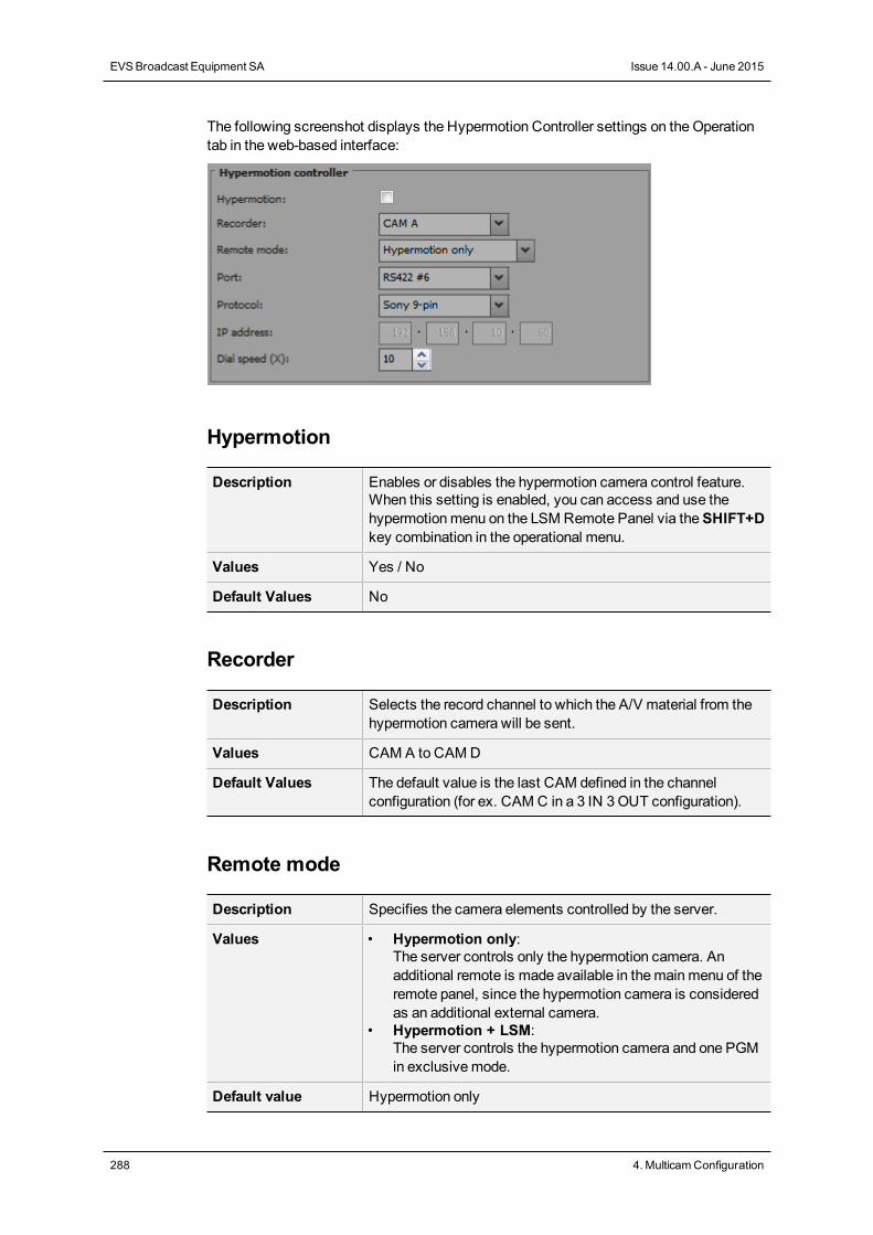
The following screenshot displays the Hypermotion Controller settings on theOperationtab in the web-based interface:
Hypermotion
Description Enables or disables the hypermotion camera control feature.When this setting is enabled, you can access and use thehypermotionmenu on the LSM Remote Panel via theSHIFT+Dkey combination in the operational menu.
Values Yes / No
Default Values No
Recorder
Description Selects the record channel to which the A/V material from thehypermotion camera will be sent.
Values CAM A to CAMD
Default Values The default value is the last CAM defined in the channelconfiguration (for ex. CAM C in a 3 IN 3OUT configuration).
Remote mode
Description Specifies the camera elements controlled by the server.
Values • Hypermotion only:The server controls only the hypermotion camera. Anadditional remote is made available in themainmenu of theremote panel, since the hypermotion camera is consideredas an additional external camera.
• Hypermotion + LSM:The server controls the hypermotion camera and one PGMin exclusivemode.
Default value Hypermotion only
288 4. MulticamConfiguration
EVSBroadcast Equipment SA Issue 14.00.A - June 2015
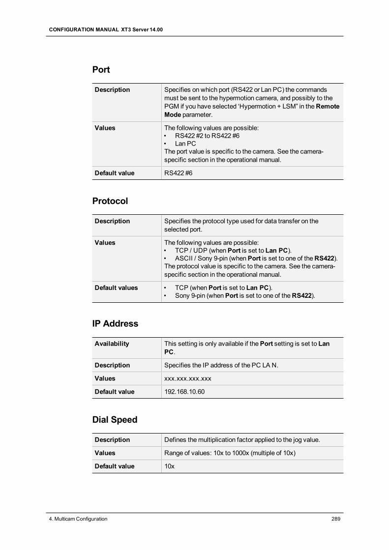
Port
Description Specifies on which port (RS422 or Lan PC) the commandsmust be sent to the hypermotion camera, and possibly to thePGM if you have selected ‘Hypermotion + LSM” in theRemoteMode parameter.
Values The following values are possible:• RS422 #2 to RS422 #6• Lan PCThe port value is specific to the camera. See the camera-specific section in the operational manual.
Default value RS422 #6
Protocol
Description Specifies the protocol type used for data transfer on theselected port.
Values The following values are possible:• TCP / UDP (whenPort is set to Lan PC).• ASCII / Sony 9-pin (whenPort is set to one of theRS422).The protocol value is specific to the camera. See the camera-specific section in the operational manual.
Default values • TCP (whenPort is set to Lan PC).• Sony 9-pin (whenPort is set to one of theRS422).
IP Address
Availability This setting is only available if thePort setting is set to LanPC.
Description Specifies the IP address of the PC LA N.
Values xxx.xxx.xxx.xxx
Default value 192.168.10.60
Dial Speed
Description Defines themultiplication factor applied to the jog value.
Values Range of values: 10x to 1000x (multiple of 10x)
Default value 10x
CONFIGURATION MANUAL XT3 Server 14.00
4. MulticamConfiguration 289
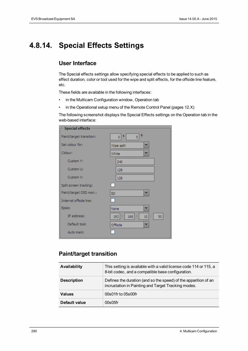
4.8.14. Special Effects Settings
User Interface
The Special effects settings allow specifying special effects to be applied to such aseffect duration, color or tool used for the wipe and split effects, for the offside line feature,etc.
These fields are available in the following interfaces:
• in theMulticam Configuration window, Operation tab
• in the Operational setupmenu of the Remote Control Panel (pages 12.X)
The following screenshot displays the Special Effects settings on theOperation tab in theweb-based interface:
Paint/target transition
Availability This setting is available with a valid license code 114 or 115, a8-bit codec, and a compatible base configuration.
Description Defines the duration (and so the speed) of the apparition of anincrustation in Painting and Target Trackingmodes.
Values 00s01fr to 05s00fr
Default value 00s05fr
290 4. MulticamConfiguration
EVSBroadcast Equipment SA Issue 14.00.A - June 2015
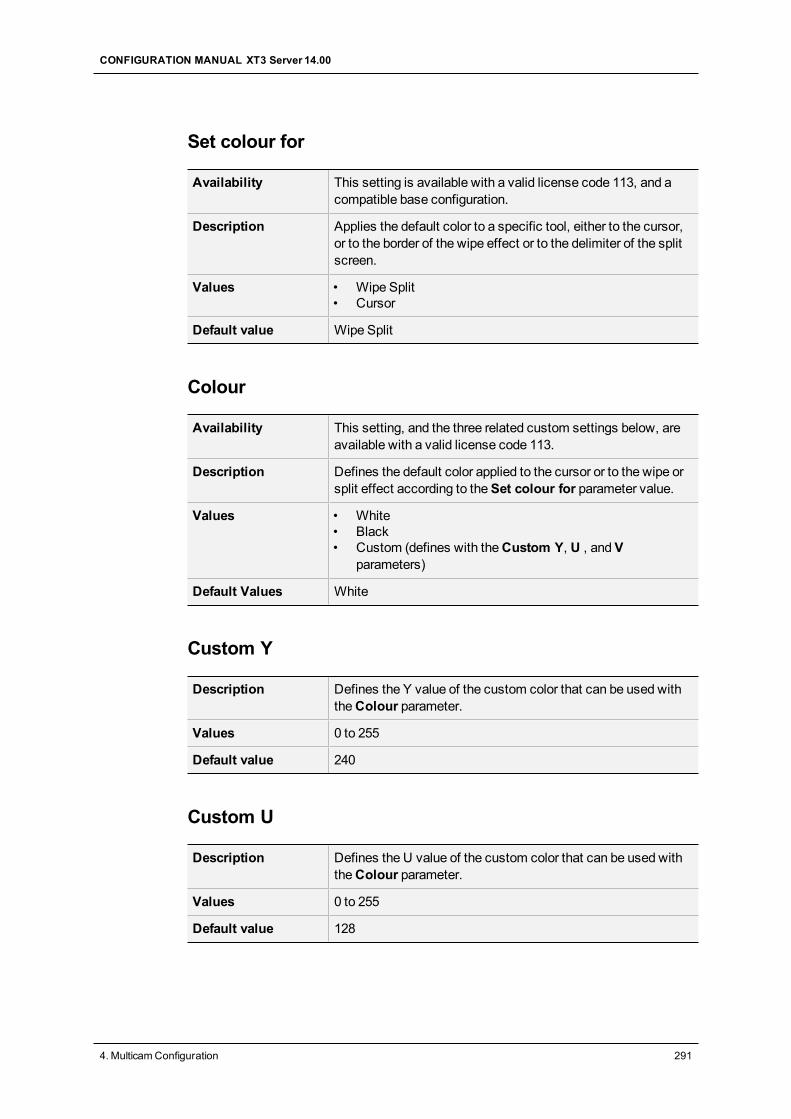
Set colour for
Availability This setting is available with a valid license code 113, and acompatible base configuration.
Description Applies the default color to a specific tool, either to the cursor,or to the border of the wipe effect or to the delimiter of the splitscreen.
Values • Wipe Split• Cursor
Default value Wipe Split
Colour
Availability This setting, and the three related custom settings below, areavailable with a valid license code 113.
Description Defines the default color applied to the cursor or to the wipe orsplit effect according to theSet colour for parameter value.
Values • White• Black• Custom (defines with theCustom Y, U , andV
parameters)
Default Values White
Custom Y
Description Defines the Y value of the custom color that can be used withtheColour parameter.
Values 0 to 255
Default value 240
Custom U
Description Defines the U value of the custom color that can be used withtheColour parameter.
Values 0 to 255
Default value 128
CONFIGURATION MANUAL XT3 Server 14.00
4. MulticamConfiguration 291
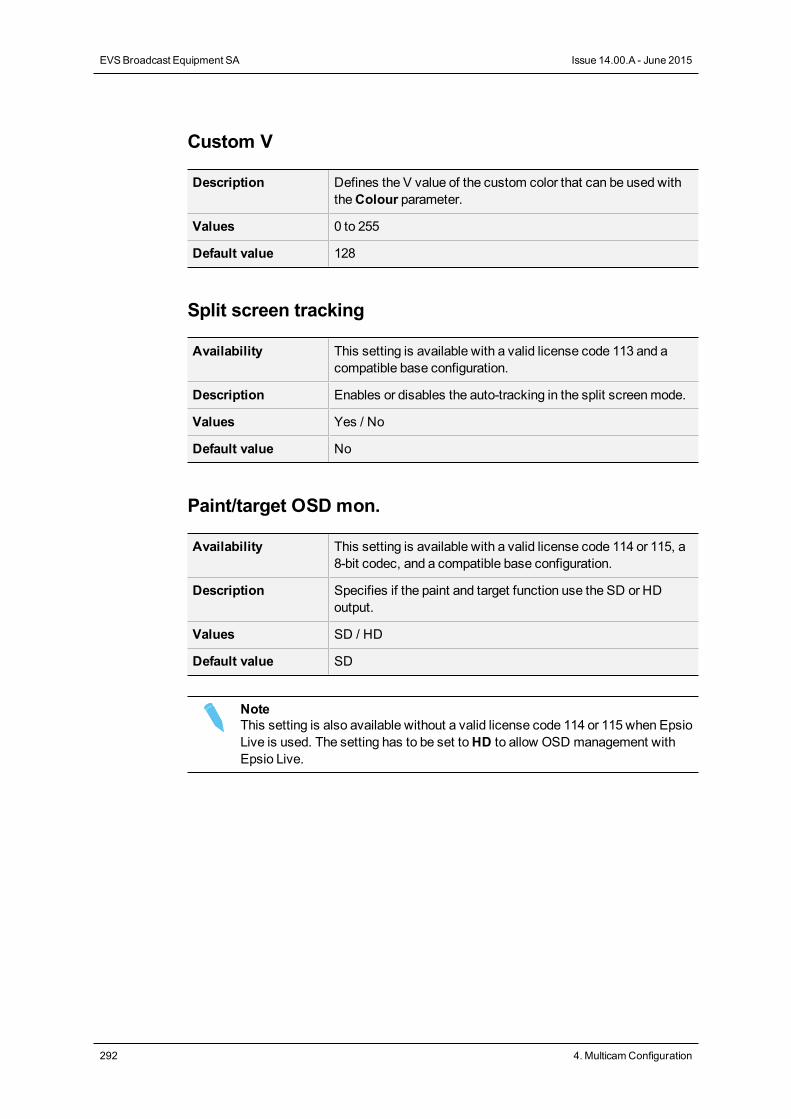
Custom V
Description Defines the V value of the custom color that can be used withtheColour parameter.
Values 0 to 255
Default value 128
Split screen tracking
Availability This setting is available with a valid license code 113 and acompatible base configuration.
Description Enables or disables the auto-tracking in the split screenmode.
Values Yes / No
Default value No
Paint/target OSD mon.
Availability This setting is available with a valid license code 114 or 115, a8-bit codec, and a compatible base configuration.
Description Specifies if the paint and target function use the SD or HDoutput.
Values SD / HD
Default value SD
NoteThis setting is also available without a valid license code 114 or 115 when EpsioLive is used. The setting has to be set toHD to allow OSD management withEpsio Live.
292 4. MulticamConfiguration
EVSBroadcast Equipment SA Issue 14.00.A - June 2015
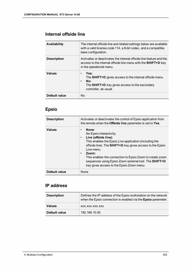
Internal offside line
Availability The internal offside line and related settings below are availablewith a valid license code 114, a 8-bit codec, and a compatiblebase configuration.
Description Activates or deactivates the internal offside line feature and theaccess to the internal offside linemenu with theSHIFT+D keyin the operational menu.
Values • Yes:TheSHIFT+D gives access to the internal offsidemenu.
• No:TheSHIFT+D key gives access to the secondarycontroller, as usual.
Default value No
Epsio
Description Activates or deactivates the control of Epsio application fromthe remote when theOffside line parameter is set toYes.
Values • None:No Epsio interactivity.
• Live (offside line):This enables the Epsio Live application (including theoffside line). TheSHIFT+D key gives access to the EpsioLivemenu.
• Zoom:This enables the connection to Epsio Zoom to create zoomsequences using Epsio Zoom external tool. TheSHIFT+Dkey gives access to the Epsio Zoommenu.
Default value None
IP address
Description Defines the IP address of the Epsio workstation on the networkwhen the Epsio connection is enabled via theEpsio parameter.
Values xxx.xxx.xxx.xxx
Default value 192.168.10.50
CONFIGURATION MANUAL XT3 Server 14.00
4. MulticamConfiguration 293
Default tool
Availability This setting is not available with Epsio Zoom.
Description Selects the tool used by default in the Epsio Livemenu on theremote when the Epsio Live connection is enabled via theEpsio parameter.
Values • Offside• Arrow• Circle• Graphics
Default value Offside
Auto mark
Description Activates / deactivates the automatic insertion of a cue pointon the record train every time the Epsio operator enters theEpsiomenu on the remote.
Values Yes / No
Default value No
294 4. MulticamConfiguration
EVSBroadcast Equipment SA Issue 14.00.A - June 2015
5. Monitoring
5.1. Server Monitoring
5.1.1. Overview on Server Monitoring WindowsThe Server Monitoring section is available by pressingSHIFT+F5 from the operationalwindows on the VGA.
NoteThis section is only available in the server-based application. It is not availablefrom the web-based interface.
It contains the pages shortly presented in the following table. The page name in this tableallows you to directly jump to the corresponding page:
Page Page Name Description
#1 GeneralInformationwindow
Provides general system information andmaintenancecommands on the EVS server.
#2 Raid and DiskStatus window
Gives information on the disks or raids from internaland/or external storage.
#3 Timecode Statuswindow
Gives information on the genlock, analog LTC andtimecode statuses from the EVS server. This page is alsoused to set up how the timecodes aremanaged in thetimecode jump tables.
#4 TimecodeMonitoring window
Displays timecode information from recorders (SD orHD).
#5 LogManagementwindow
Allows a user-friendly and easy management of the logs.
CONFIGURATION MANUAL XT3 Server 14.00
5. Monitoring 295
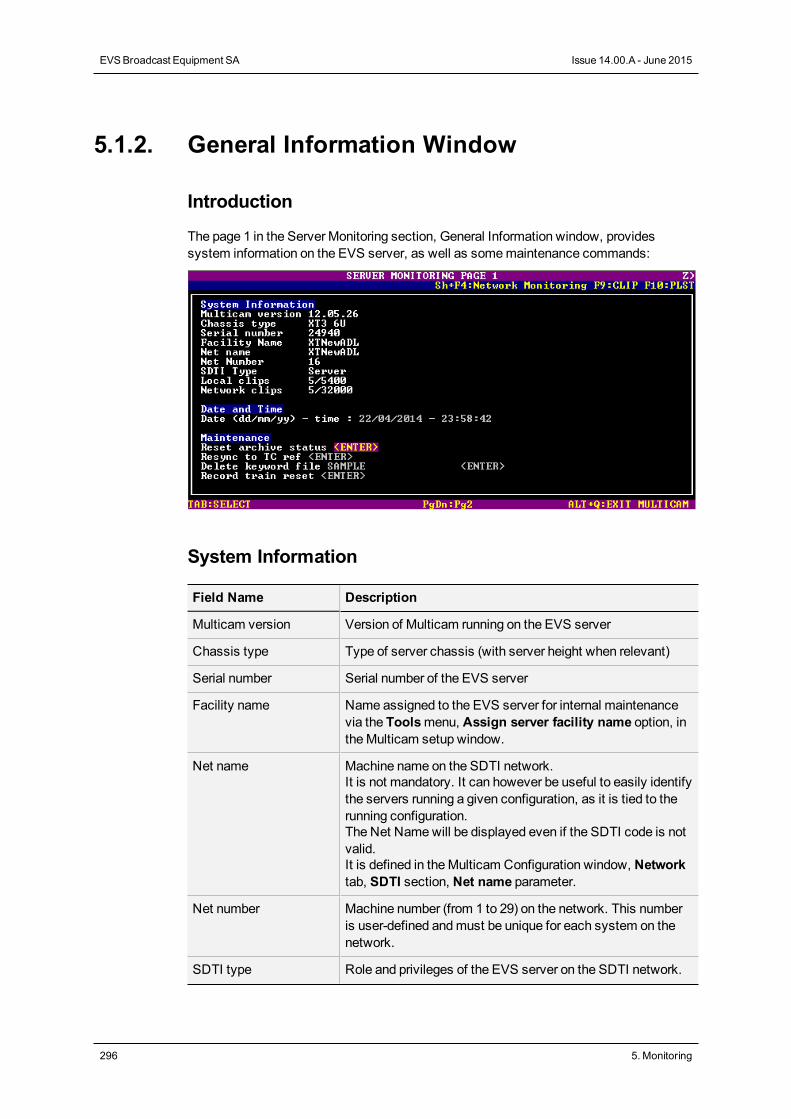
5.1.2. General Information Window
Introduction
The page 1 in the Server Monitoring section, General Information window, providessystem information on the EVS server, as well as somemaintenance commands:
System Information
Field Name Description
Multicam version Version of Multicam running on the EVS server
Chassis type Type of server chassis (with server height when relevant)
Serial number Serial number of the EVS server
Facility name Name assigned to the EVS server for internal maintenancevia the Toolsmenu, Assign server facility name option, intheMulticam setup window.
Net name Machine name on the SDTI network.It is not mandatory. It can however be useful to easily identifythe servers running a given configuration, as it is tied to therunning configuration.The Net Namewill be displayed even if the SDTI code is notvalid.It is defined in theMulticam Configuration window, Networktab, SDTI section, Net name parameter.
Net number Machine number (from 1 to 29) on the network. This numberis user-defined andmust be unique for each system on thenetwork.
SDTI type Role and privileges of the EVS server on the SDTI network.
296 5. Monitoring
EVSBroadcast Equipment SA Issue 14.00.A - June 2015
Field Name Description
Local clips Number of clips (out of themax. clip numbers) stored locallyon the EVS server.
Network clips Number of clips (out of themax. clip numbers) stored on theXNet network.
Date and Time
This section specifies the date and time of the EVS server.
Maintenance
This section provides some commands to perform the followingmaintenance actions:
Command Description
Reset archive status Resets the flag of all clips whose archive status has beenenabled with the Archive fonction on the Remote panel.
Resync to TC ref Resynchronizes the server timecode to the timecodereference.
Delete keyword file Deletes the selected keyword file. Press SPACEBAR untilyou select the keyword file to remove, and press ENTER.
Record train reset Resets the record trains before their field counter overflows.Users are requested to confirm the action before performingthe reset. See section "Record Train Maintenance" on page44
Reconnect PC LAN Reinitiates the PC LAN connexion. This option is onlyavailable on EVS servers fitted with an HS870MTPC board.It prevents users from having to reboot the EVS server whenthe PC LAN has been disconnected and connected again, butthe PC LAN connection status does not update properly.
CONFIGURATION MANUAL XT3 Server 14.00
5. Monitoring 297
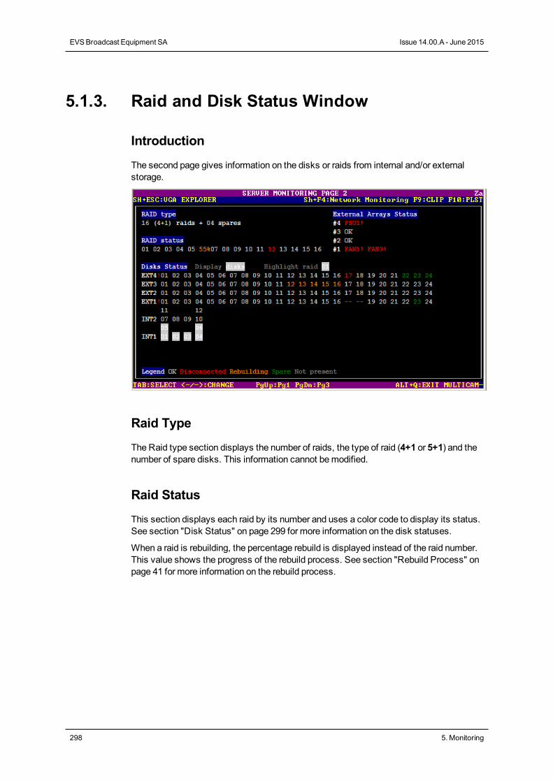
5.1.3. Raid and Disk Status Window
Introduction
The second page gives information on the disks or raids from internal and/or externalstorage.
Raid Type
The Raid type section displays the number of raids, the type of raid (4+1 or 5+1) and thenumber of spare disks. This information cannot bemodified.
Raid Status
This section displays each raid by its number and uses a color code to display its status.See section "Disk Status" on page 299 for more information on the disk statuses.
When a raid is rebuilding, the percentage rebuild is displayed instead of the raid number.This value shows the progress of the rebuild process. See section "Rebuild Process" onpage 41 for more information on the rebuild process.
298 5. Monitoring
EVSBroadcast Equipment SA Issue 14.00.A - June 2015
External Array Status
This section displays the status of each external array and potential alerts:
Status Meaning
OK No alert
PSU1!, PSU2! Problem with a power supply unit
FAN1!, FAN2! or FAN3! Problem with a fan
Disk Status
This section provides a representation of the disks contained in the external and/or internalarrays, as well as their status, which can be as follows:
Color Code Raid Status
Light gray OK: The disk is connected in a raid.
Red Disconnected: The disk is physically present but disconnected by thesoftware.
Orange Rebuilding: The disk is being rebuilt.
Green Spare: The disk is connected but is not included in a raid.
gray dashes Not present: The disk is not physically connected to the hardware.
How to Change the Disk Status Display
Based on the selectionmade in theDisplay field, two types of representations areavailable: by disk number or by raid number. Users can change the option by using theSpacebar, the plus (+) andminus (-) keys, as well as the arrow keys.
CONFIGURATION MANUAL XT3 Server 14.00
5. Monitoring 299
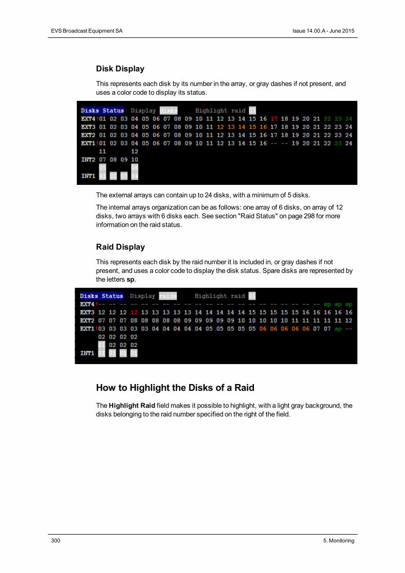
Disk Display
This represents each disk by its number in the array, or gray dashes if not present, anduses a color code to display its status.
The external arrays can contain up to 24 disks, with aminimum of 5 disks.
The internal arrays organization can be as follows: one array of 6 disks, on array of 12disks, two arrays with 6 disks each. See section "Raid Status" on page 298 for moreinformation on the raid status.
Raid Display
This represents each disk by the raid number it is included in, or gray dashes if notpresent, and uses a color code to display the disk status. Spare disks are represented bythe letters sp.
How to Highlight the Disks of a Raid
TheHighlight Raid field makes it possible to highlight, with a light gray background, thedisks belonging to the raid number specified on the right of the field.
300 5. Monitoring
EVSBroadcast Equipment SA Issue 14.00.A - June 2015
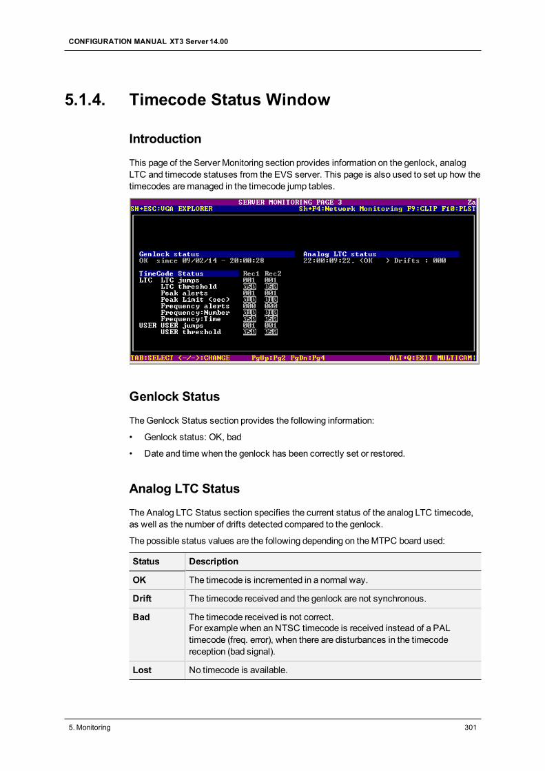
5.1.4. Timecode Status Window
Introduction
This page of the Server Monitoring section provides information on the genlock, analogLTC and timecode statuses from the EVS server. This page is also used to set up how thetimecodes aremanaged in the timecode jump tables.
Genlock Status
TheGenlock Status section provides the following information:
• Genlock status: OK, bad
• Date and time when the genlock has been correctly set or restored.
Analog LTC Status
The Analog LTC Status section specifies the current status of the analog LTC timecode,as well as the number of drifts detected compared to the genlock.
The possible status values are the following depending on theMTPC board used:
Status Description
OK The timecode is incremented in a normal way.
Drift The timecode received and the genlock are not synchronous.
Bad The timecode received is not correct.For example when an NTSC timecode is received instead of a PALtimecode (freq. error), when there are disturbances in the timecodereception (bad signal).
Lost No timecode is available.
CONFIGURATION MANUAL XT3 Server 14.00
5. Monitoring 301
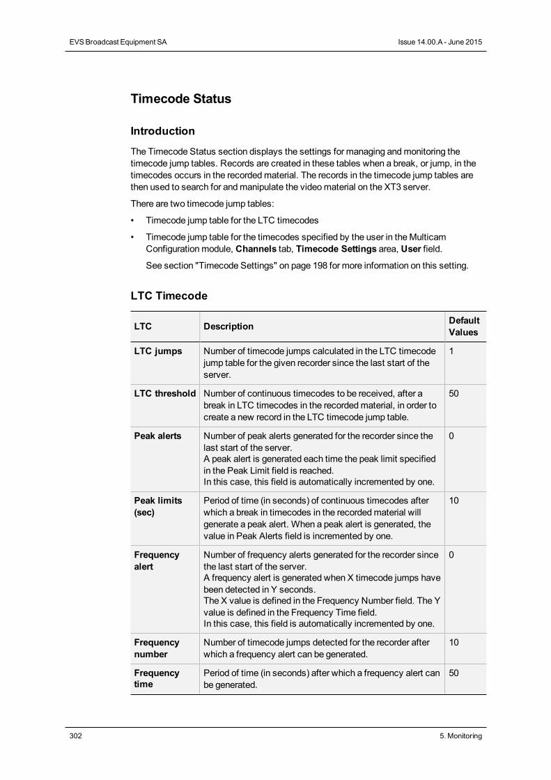
Timecode Status
Introduction
The Timecode Status section displays the settings for managing andmonitoring thetimecode jump tables. Records are created in these tables when a break, or jump, in thetimecodes occurs in the recordedmaterial. The records in the timecode jump tables arethen used to search for andmanipulate the videomaterial on the XT3 server.
There are two timecode jump tables:
• Timecode jump table for the LTC timecodes
• Timecode jump table for the timecodes specified by the user in theMulticamConfigurationmodule, Channels tab, Timecode Settings area, User field.
See section "Timecode Settings" on page 198 for more information on this setting.
LTC Timecode
LTC Description DefaultValues
LTC jumps Number of timecode jumps calculated in the LTC timecodejump table for the given recorder since the last start of theserver.
1
LTC threshold Number of continuous timecodes to be received, after abreak in LTC timecodes in the recordedmaterial, in order tocreate a new record in the LTC timecode jump table.
50
Peak alerts Number of peak alerts generated for the recorder since thelast start of the server.A peak alert is generated each time the peak limit specifiedin the Peak Limit field is reached.In this case, this field is automatically incremented by one.
0
Peak limits(sec)
Period of time (in seconds) of continuous timecodes afterwhich a break in timecodes in the recordedmaterial willgenerate a peak alert. When a peak alert is generated, thevalue in Peak Alerts field is incremented by one.
10
Frequencyalert
Number of frequency alerts generated for the recorder sincethe last start of the server.A frequency alert is generated when X timecode jumps havebeen detected in Y seconds.The X value is defined in the Frequency Number field. The Yvalue is defined in the Frequency Time field.In this case, this field is automatically incremented by one.
0
Frequencynumber
Number of timecode jumps detected for the recorder afterwhich a frequency alert can be generated.
10
Frequencytime
Period of time (in seconds) after which a frequency alert canbe generated.
50
302 5. Monitoring
EVSBroadcast Equipment SA Issue 14.00.A - June 2015
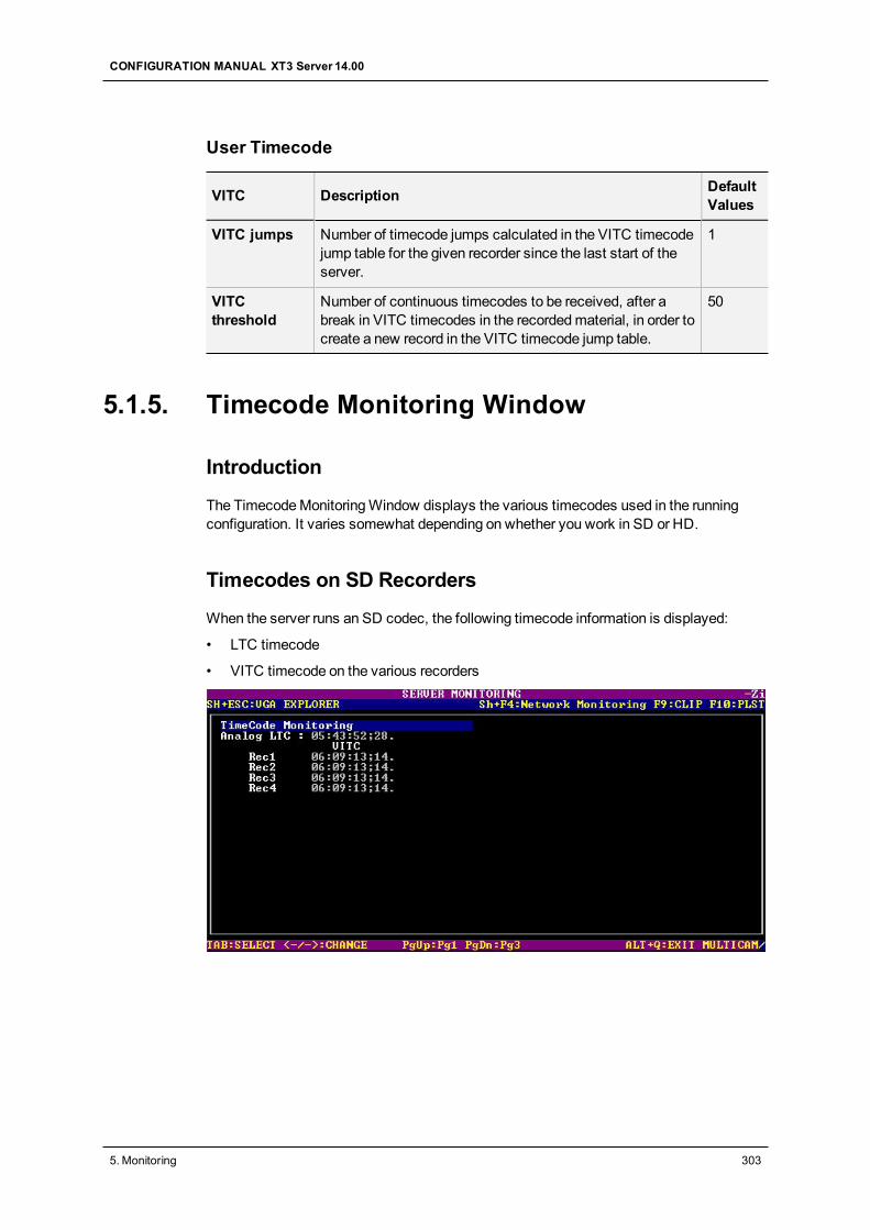
User Timecode
VITC Description DefaultValues
VITC jumps Number of timecode jumps calculated in the VITC timecodejump table for the given recorder since the last start of theserver.
1
VITCthreshold
Number of continuous timecodes to be received, after abreak in VITC timecodes in the recordedmaterial, in order tocreate a new record in the VITC timecode jump table.
50
5.1.5. Timecode Monitoring Window
Introduction
The TimecodeMonitoringWindow displays the various timecodes used in the runningconfiguration. It varies somewhat depending on whether you work in SD or HD.
Timecodes on SD Recorders
When the server runs an SD codec, the following timecode information is displayed:
• LTC timecode
• VITC timecode on the various recorders
CONFIGURATION MANUAL XT3 Server 14.00
5. Monitoring 303
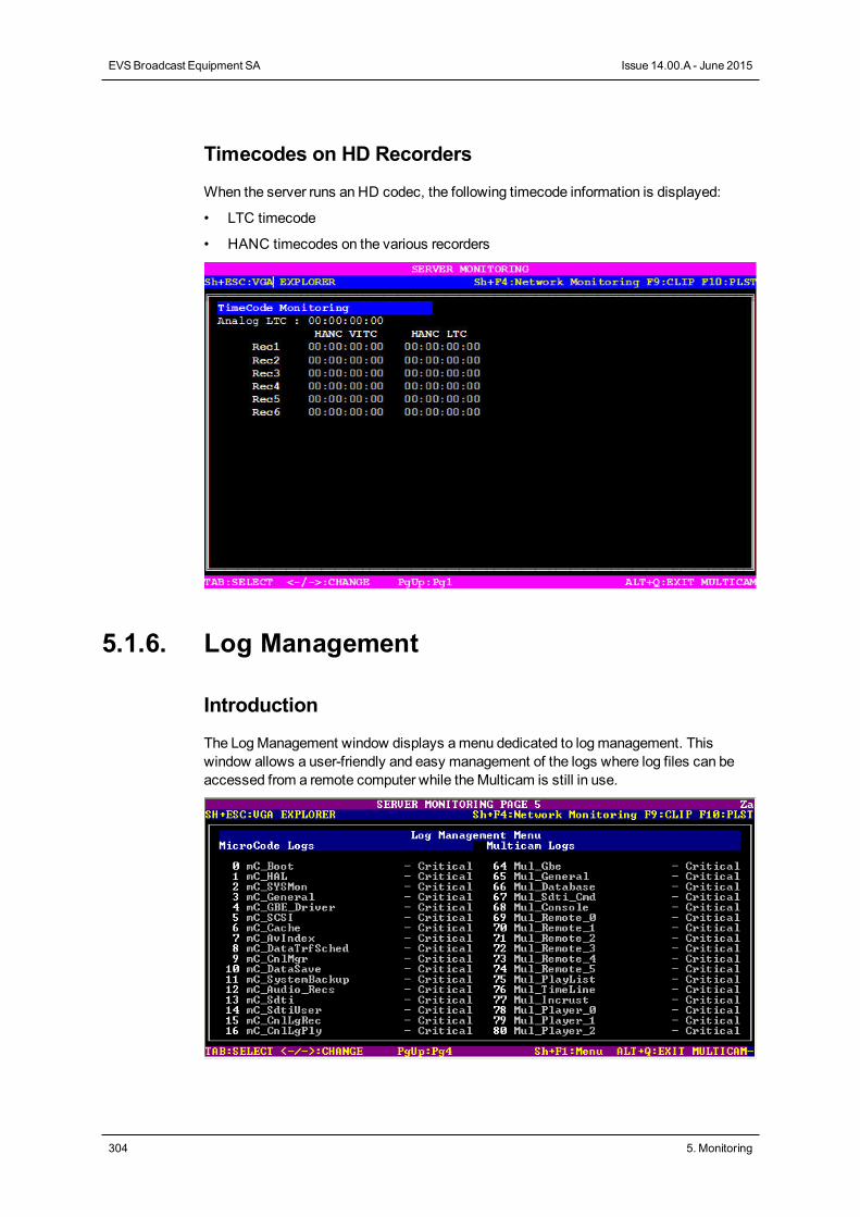
Timecodes on HD Recorders
When the server runs an HD codec, the following timecode information is displayed:
• LTC timecode
• HANC timecodes on the various recorders
5.1.6. Log Management
Introduction
The LogManagement window displays amenu dedicated to logmanagement. Thiswindow allows a user-friendly and easy management of the logs where log files can beaccessed from a remote computer while theMulticam is still in use.
304 5. Monitoring
EVSBroadcast Equipment SA Issue 14.00.A - June 2015
Log File Types
The left column displays items related tomicrocode. The right column displays those oftheMulticam.
Each item has two associated log files:
• a regular log file
• a log file logging only errors
Criticality Levels
Each item has a criticality level that can bemodified:
• The lowest and default level of criticality is Critical, where the log is limited torecording critical and important commands. This is the default value for all items.
• An intermediate level is Normal.
• The highest level is Debugwhich basically records every command.
This highest level should never be chosen without advice of qualified EVS staff.
You can press SHIFT+F1 to access a help screen that provides information on allcommands available in this window.
WarningWhen you have to switch toDebugmode, first reproduce the problem, thenextract the logs, and finally switch back to the default Criticalmode.
Extracting Log Files
This window also offers the ability to extract log files when theMulticam is running.
When the LogManagement window is open, press E to extracts the log files instantly sothat a user can access them through a common FTP client application from a remotecomputer.
The extracted files are located in C:\LSMCE\DATA\LOG. Their name starts with anunderscore: The regular log file Multicam_Database.log is renamed _Multicam_Database.log once extracted when the application is running.
NoteYou can extract logs from the XNetMonitor for any server running on the XNetnetwork. For more information, refer to the XNetMonitor manual.
CONFIGURATION MANUAL XT3 Server 14.00
5. Monitoring 305
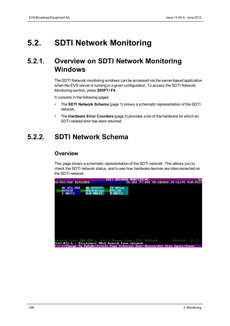
5.2. SDTI Network Monitoring
5.2.1. Overview on SDTI Network MonitoringWindowsThe SDTI Network monitoring windows can be accessed via the server-based applicationwhen the EVS server is running in a given configuration. To access the SDTI NetworkMonitoring section, press SHIFT+F4.
It consists in the following pages:
• TheSDTI Network Schema (page 1) shows a schematic representation of the SDTInetwork.
• TheHardware Error Counters (page 2) provides a list of the hardware for which anSDTI-related error has been returned .
5.2.2. SDTI Network Schema
Overview
This page shows a schematic representation of the SDTI network. This allows you tocheck the SDTI network status, and to see how hardware devices are interconnected onthe SDTI network.
306 5. Monitoring
EVSBroadcast Equipment SA Issue 14.00.A - June 2015
Data Displayed
All machines are displayed in the logical connection order, i.e. the way they are effectivelyconnected on the network.
For eachmachine, the following information is displayed:
• net number + name
• serial number
• main network configuration setting (server, master or client) as defined in the EVSapplication.
Background Color
The background color of the data related to a givenmachinemeans:
• blue: effective server
• gray: not currently server
Text Color
The color of the text indicates the video network overload, based on how many SDTInetwork mailboxes are used:
• white: (OK)
Less than 90% of the network capacity is used.
• red: (warning)
Over 90% of the network capacity is used, and the network risks to be overloaded.
Link Color
The color of the link indicates the physical link status between twomachines:
• green:OK
• red: errors
CONFIGURATION MANUAL XT3 Server 14.00
5. Monitoring 307
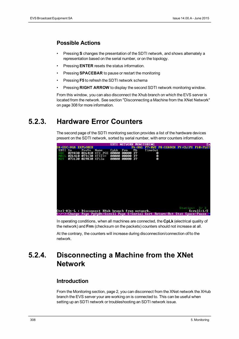
Possible Actions
• PressingS changes the presentation of the SDTI network, and shows alternately arepresentation based on the serial number, or on the topology.
• PressingENTER resets the status information.
• PressingSPACEBAR to pause or restart themonitoring
• Pressing F5 to refresh the SDTI network schema
• PressingRIGHT ARROW to display the second SDTI network monitoring window.
From this window, you can also disconnect the Xhub branch on which the EVS server islocated from the network. See section "Disconnecting aMachine from the XNet Network"on page 308 for more information.
5.2.3. Hardware Error CountersThe second page of the SDTI monitoring section provides a list of the hardware devicespresent on the SDTI network, sorted by serial number, with error counters information.
In operating conditions, when all machines are connected, theCpLk (electrical quality ofthe network) and Frm (checksum on the packets) counters should not increase at all.
At the contrary, the counters will increase during disconnection/connection of/to thenetwork.
5.2.4. Disconnecting a Machine from the XNetNetwork
Introduction
From theMonitoring section, page 2, you can disconnect from the XNet network the XHubbranch the EVS server your are working on is connected to. This can be useful whensetting up an SDTI network or troubleshooting an SDTI network issue.
308 5. Monitoring
EVSBroadcast Equipment SA Issue 14.00.A - June 2015
This feature is only possible when using a XHub from version 3.03.
How to Disconnect a Machine from the XNet Network
To disconnect amachine from the server, proceed as follows:
1. Press SHIFT- F4 to access the SDTI Network Monitoring window.
2. Press CTRL-ALT-L to disconnect the XHub branch from the network.
The following warning is displayed: 'The network branch you areconnected on will be disconnected from the network. Allnetwork actions will be disabled.'
3. Click ENTER to confirm that you want to disconnect the XHub branch from thenetwork.
On the SDTI Network Monitoring window, the followingmessage in red font informs thatthemachine is disconnected and how it can be connected again:
'XHub branch disconnected from the network. Press CTRL-ALT-L toreconnect.'
5.3. Protocols
5.3.1. IntroductionThe EVS servers can be controlled by several protocols. This section will describe brieflythe supported protocols. The purpose of this description is not to be exhaustive but to givea quick overview of the protocols capabilities and the function supported.
5.3.2. Sony BVW75
Protocol Capabilities
This Sony protocol is able to:
• use the transport command
• get the channel status
• get the channel TC
Characteristics
Bitrates
38.4 kilobits/s
CONFIGURATION MANUAL XT3 Server 14.00
5. Monitoring 309
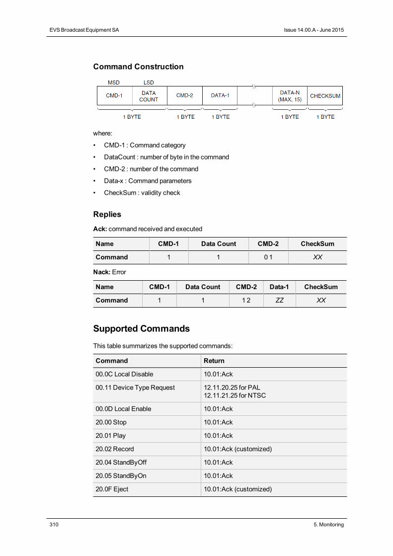
Command Construction
where:
• CMD-1 : Command category
• DataCount : number of byte in the command
• CMD-2 : number of the command
• Data-x : Command parameters
• CheckSum : validity check
Replies
Ack: command received and executed
Name CMD-1 Data Count CMD-2 CheckSum
Command 1 1 0 1 XX
Nack:Error
Name CMD-1 Data Count CMD-2 Data-1 CheckSum
Command 1 1 1 2 ZZ XX
Supported Commands
This table summarizes the supported commands:
Command Return
00.0C Local Disable 10.01:Ack
00.11 Device Type Request 12.11.20.25 for PAL12.11.21.25 for NTSC
00.0D Local Enable 10.01:Ack
20.00 Stop 10.01:Ack
20.01 Play 10.01:Ack
20.02 Record 10.01:Ack (customized)
20.04 StandByOff 10.01:Ack
20.05 StandByOn 10.01:Ack
20.0F Eject 10.01:Ack (customized)
310 5. Monitoring
EVSBroadcast Equipment SA Issue 14.00.A - June 2015
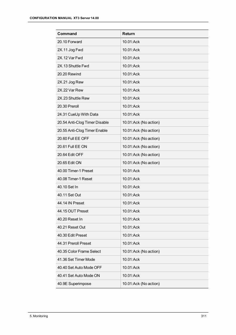
Command Return
20.10 Forward 10.01:Ack
2X.11 Jog Fwd 10.01:Ack
2X.12 Var Fwd 10.01:Ack
2X.13 Shuttle Fwd 10.01:Ack
20.20 Rewind 10.01:Ack
2X.21 Jog Rew 10.01:Ack
2X.22 Var Rew 10.01:Ack
2X.23 Shuttle Rew 10.01:Ack
20.30 Preroll 10.01:Ack
24.31 CueUpWith Data 10.01:Ack
20.54 Anti-Clog Timer Disable 10.01:Ack (No action)
20.55 Anti-Clog Timer Enable 10.01:Ack (No action)
20.60 Full EE OFF 10.01:Ack (No action)
20.61 Full EE ON 10.01:Ack (No action)
20.64 Edit OFF 10.01:Ack (No action)
20.65 Edit ON 10.01:Ack (No action)
40.00 Timer-1 Preset 10.01:Ack
40.08 Timer-1 Reset 10.01:Ack
40.10 Set In 10.01:Ack
40.11 Set Out 10.01:Ack
44.14 IN Preset 10.01:Ack
44.15 OUT Preset 10.01:Ack
40.20 Reset In 10.01:Ack
40.21 Reset Out 10.01:Ack
40.30 Edit Preset 10.01:Ack
44.31 Preroll Preset 10.01:Ack
40.35 Color Frame Select 10.01:Ack (No action)
41.36 Set TimerMode 10.01:Ack
40.40 Set AutoModeOFF 10.01:Ack
40.41 Set AutoModeON 10.01:Ack
40.9E Superimpose 10.01:Ack (No action)
CONFIGURATION MANUAL XT3 Server 14.00
5. Monitoring 311
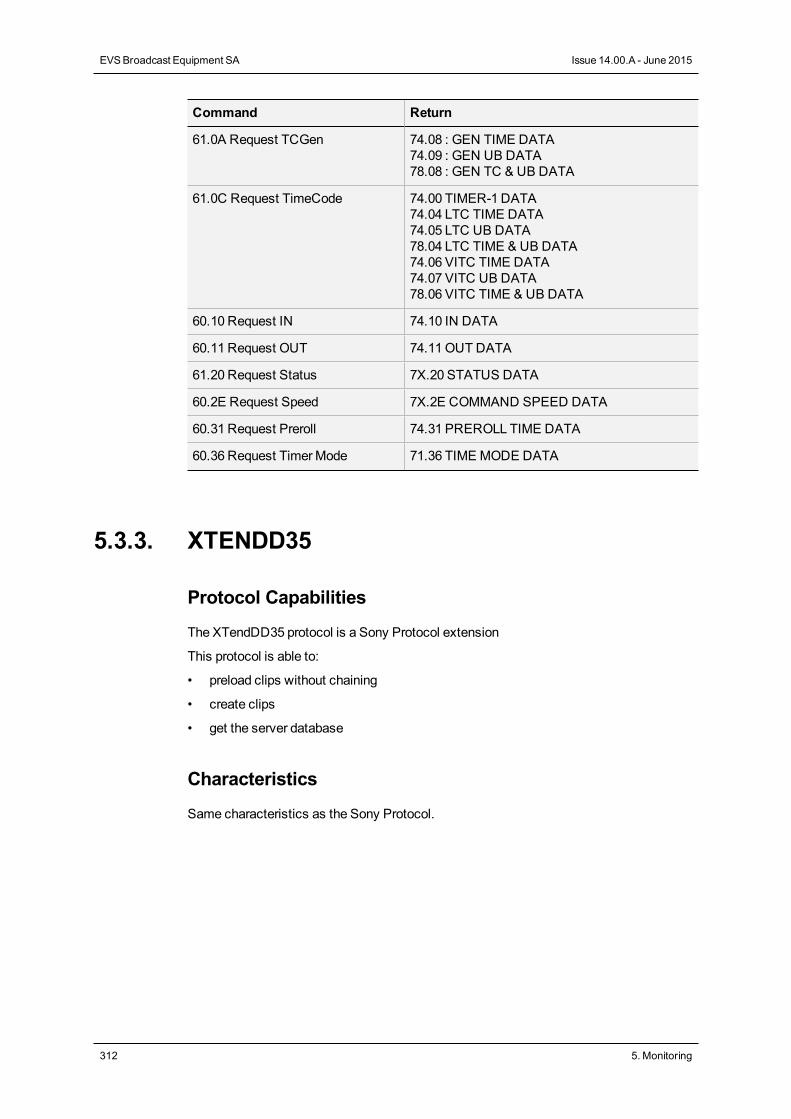
Command Return
61.0A Request TCGen 74.08 : GEN TIME DATA74.09 : GEN UB DATA78.08 : GEN TC & UB DATA
61.0C Request TimeCode 74.00 TIMER-1 DATA74.04 LTC TIME DATA74.05 LTC UB DATA78.04 LTC TIME & UB DATA74.06 VITC TIME DATA74.07 VITC UB DATA78.06 VITC TIME & UB DATA
60.10 Request IN 74.10 IN DATA
60.11 Request OUT 74.11OUT DATA
61.20 Request Status 7X.20 STATUS DATA
60.2E Request Speed 7X.2E COMMAND SPEED DATA
60.31 Request Preroll 74.31 PREROLL TIME DATA
60.36 Request TimerMode 71.36 TIME MODE DATA
5.3.3. XTENDD35
Protocol Capabilities
The XTendDD35 protocol is a Sony Protocol extension
This protocol is able to:
• preload clips without chaining
• create clips
• get the server database
Characteristics
Same characteristics as the Sony Protocol.
312 5. Monitoring
EVSBroadcast Equipment SA Issue 14.00.A - June 2015
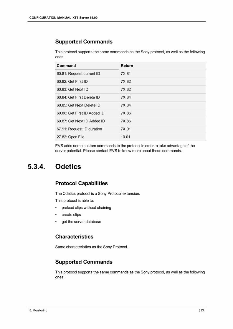
Supported Commands
This protocol supports the same commands as the Sony protocol, as well as the followingones:
Command Return
60.81: Request current ID 7X.81
60.82: Get First ID 7X.82
60.83: Get Next ID 7X.82
60.84: Get First Delete ID 7X.84
60.85: Get Next Delete ID 7X.84
60.86: Get First ID Added ID 7X.86
60.87: Get Next ID Added ID 7X.86
67.91: Request ID duration 7X.91
27.82: Open File 10.01
EVS adds some custom commands to the protocol in order to take advantage of theserver potential. Please contact EVS to know more about these commands.
5.3.4. Odetics
Protocol Capabilities
TheOdetics protocol is a Sony Protocol extension.
This protocol is able to:
• preload clips without chaining
• create clips
• get the server database
Characteristics
Same characteristics as the Sony Protocol.
Supported Commands
This protocol supports the same commands as the Sony protocol, as well as the followingones:
CONFIGURATION MANUAL XT3 Server 14.00
5. Monitoring 313
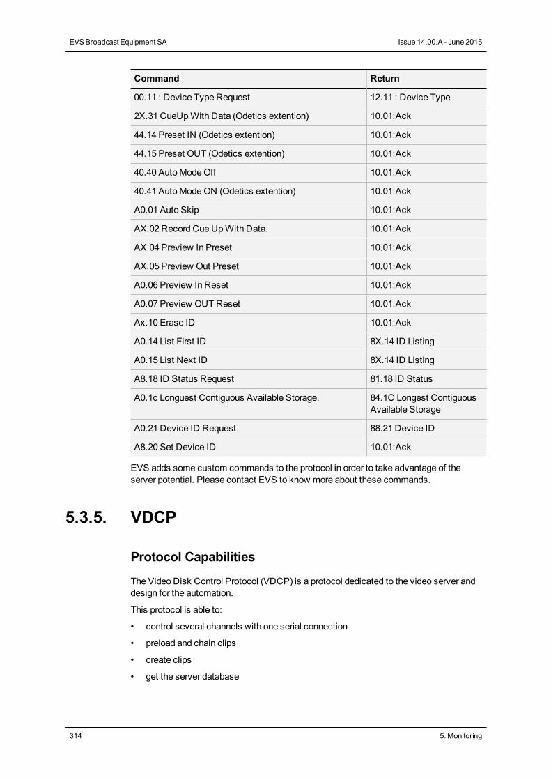
Command Return
00.11 : Device Type Request 12.11 : Device Type
2X.31 CueUpWith Data (Odetics extention) 10.01:Ack
44.14 Preset IN (Odetics extention) 10.01:Ack
44.15 Preset OUT (Odetics extention) 10.01:Ack
40.40 AutoModeOff 10.01:Ack
40.41 AutoModeON (Odetics extention) 10.01:Ack
A0.01 Auto Skip 10.01:Ack
AX.02 Record Cue UpWith Data. 10.01:Ack
AX.04 Preview In Preset 10.01:Ack
AX.05 Preview Out Preset 10.01:Ack
A0.06 Preview In Reset 10.01:Ack
A0.07 Preview OUT Reset 10.01:Ack
Ax.10 Erase ID 10.01:Ack
A0.14 List First ID 8X.14 ID Listing
A0.15 List Next ID 8X.14 ID Listing
A8.18 ID Status Request 81.18 ID Status
A0.1c Longuest Contiguous Available Storage. 84.1C Longest ContiguousAvailable Storage
A0.21 Device ID Request 88.21 Device ID
A8.20 Set Device ID 10.01:Ack
EVS adds some custom commands to the protocol in order to take advantage of theserver potential. Please contact EVS to know more about these commands.
5.3.5. VDCP
Protocol Capabilities
The Video Disk Control Protocol (VDCP) is a protocol dedicated to the video server anddesign for the automation.
This protocol is able to:
• control several channels with one serial connection
• preload and chain clips
• create clips
• get the server database
314 5. Monitoring
EVSBroadcast Equipment SA Issue 14.00.A - June 2015
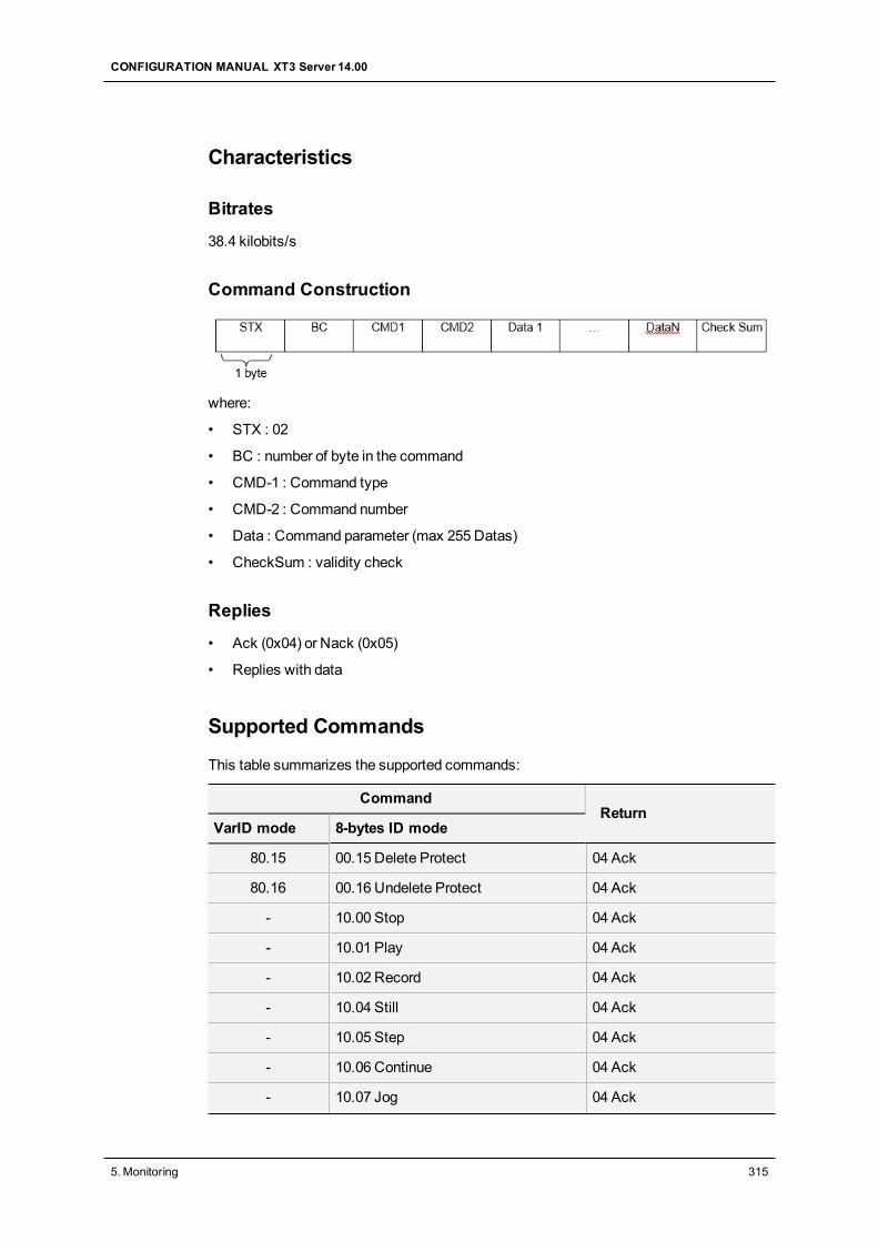
Characteristics
Bitrates
38.4 kilobits/s
Command Construction
where:
• STX : 02
• BC : number of byte in the command
• CMD-1 : Command type
• CMD-2 : Command number
• Data : Command parameter (max 255 Datas)
• CheckSum : validity check
Replies
• Ack (0x04) or Nack (0x05)
• Replies with data
Supported Commands
This table summarizes the supported commands:
CommandReturn
VarID mode 8-bytes ID mode
80.15 00.15 Delete Protect 04 Ack
80.16 00.16 Undelete Protect 04 Ack
- 10.00 Stop 04 Ack
- 10.01 Play 04 Ack
- 10.02 Record 04 Ack
- 10.04 Still 04 Ack
- 10.05 Step 04 Ack
- 10.06 Continue 04 Ack
- 10.07 Jog 04 Ack
CONFIGURATION MANUAL XT3 Server 14.00
5. Monitoring 315
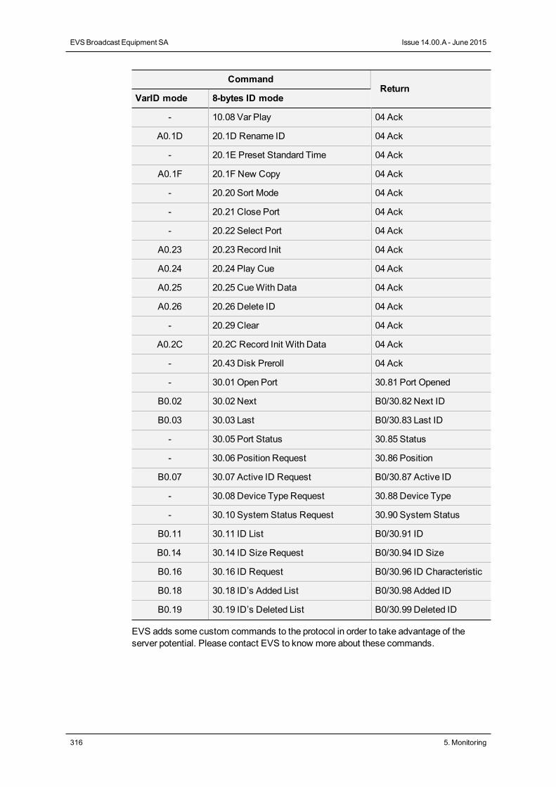
CommandReturn
VarID mode 8-bytes ID mode
- 10.08 Var Play 04 Ack
A0.1D 20.1D Rename ID 04 Ack
- 20.1E Preset Standard Time 04 Ack
A0.1F 20.1F New Copy 04 Ack
- 20.20 Sort Mode 04 Ack
- 20.21 Close Port 04 Ack
- 20.22 Select Port 04 Ack
A0.23 20.23 Record Init 04 Ack
A0.24 20.24 Play Cue 04 Ack
A0.25 20.25 CueWith Data 04 Ack
A0.26 20.26 Delete ID 04 Ack
- 20.29 Clear 04 Ack
A0.2C 20.2C Record Init With Data 04 Ack
- 20.43 Disk Preroll 04 Ack
- 30.01 Open Port 30.81 Port Opened
B0.02 30.02 Next B0/30.82 Next ID
B0.03 30.03 Last B0/30.83 Last ID
- 30.05 Port Status 30.85 Status
- 30.06 Position Request 30.86 Position
B0.07 30.07 Active ID Request B0/30.87 Active ID
- 30.08 Device Type Request 30.88 Device Type
- 30.10 System Status Request 30.90 System Status
B0.11 30.11 ID List B0/30.91 ID
B0.14 30.14 ID Size Request B0/30.94 ID Size
B0.16 30.16 ID Request B0/30.96 ID Characteristic
B0.18 30.18 ID’s Added List B0/30.98 Added ID
B0.19 30.19 ID’s Deleted List B0/30.99 Deleted ID
EVS adds some custom commands to the protocol in order to take advantage of theserver potential. Please contact EVS to know more about these commands.
316 5. Monitoring
EVSBroadcast Equipment SA Issue 14.00.A - June 2015

6. Truck Manager Plugin
6.1. Introduction
Plugin Integration into Truck Manager
This chapter describes theMulticam plugin for the Truck Manager application.
TheMulticam plugin consists of a list of operational settings relevant for Multicam. Thesesettings are displayed in a specific area in the Truck Manager application, in the lower partof the Configuration pane.
TheMulticam plugin allows users to define and apply remotely the settings required for theMulticam application to be operational.
Plugin Delivery
The plugin is delivered with theMulticam application.
The Truck Manager application automatically downloads the right plugin version when itconnects to an EVS server for the first time on a given setup.
For this reason, the version of the Truck Manager is not tied to a given plugin version of theMulticam application.
CONFIGURATION MANUAL XT3 Server 14.00
6. TruckManager Plugin 317
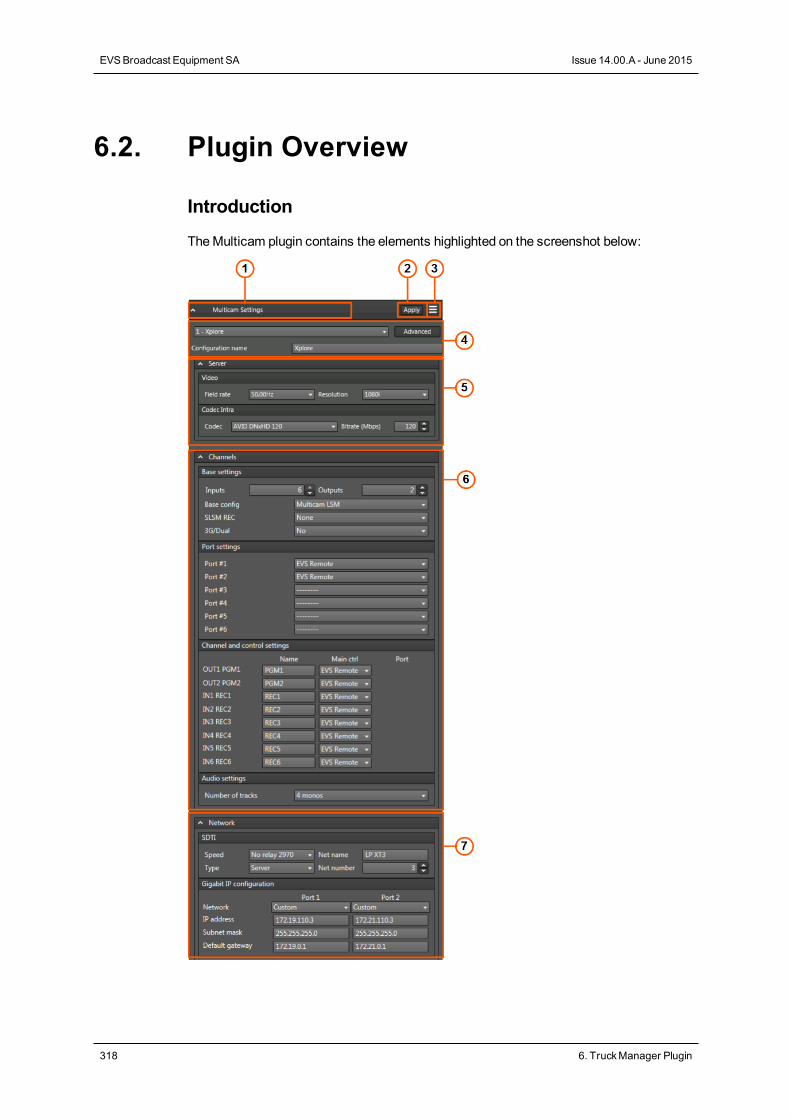
6.2. Plugin Overview
Introduction
TheMulticam plugin contains the elements highlighted on the screenshot below:
318 6. TruckManager Plugin
EVSBroadcast Equipment SA Issue 14.00.A - June 2015
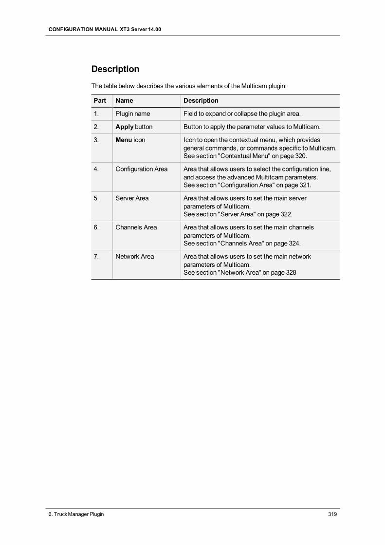
Description
The table below describes the various elements of theMulticam plugin:
Part Name Description
1. Plugin name Field to expand or collapse the plugin area.
2. Apply button Button to apply the parameter values toMulticam.
3. Menu icon Icon to open the contextual menu, which providesgeneral commands, or commands specific to Multicam.See section "Contextual Menu" on page 320.
4. Configuration Area Area that allows users to select the configuration line,and access the advancedMultitcam parameters.See section "Configuration Area" on page 321.
5. Server Area Area that allows users to set themain serverparameters of Multicam.See section "Server Area" on page 322.
6. Channels Area Area that allows users to set themain channelsparameters of Multicam.See section "Channels Area" on page 324.
7. Network Area Area that allows users to set themain networkparameters of Multicam.See section "Network Area" on page 328
CONFIGURATION MANUAL XT3 Server 14.00
6. TruckManager Plugin 319
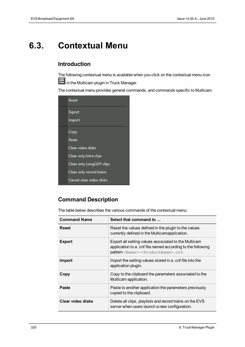
6.3. Contextual Menu
Introduction
The following contextual menu is available when you click on the contextual menu icon
in theMulticam plugin in Truck Manager.
The contextual menu provides general commands, and commands specific to Multicam.
Command Description
The table below describes the various commands of the contextual menu:
Command Name Select that command to ...
Reset Reset the values defined in the plugin to the valuescurrently defined in theMulticamapplication.
Export Export all setting values associated to theMulticamapplication to a .cnf file named according to the followingpattern <Name>-<ProductName>.cnf.
Import Import the setting values stored in a .cnf file into theapplication plugin.
Copy Copy to the clipboard the parameters associated to theMulticam application.
Paste Paste to another application the parameters previouslycopied to the clipboard.
Clear video disks Delete all clips, playlists and record trains on the EVSserver when users launch a new configuration.
320 6. TruckManager Plugin
EVSBroadcast Equipment SA Issue 14.00.A - June 2015
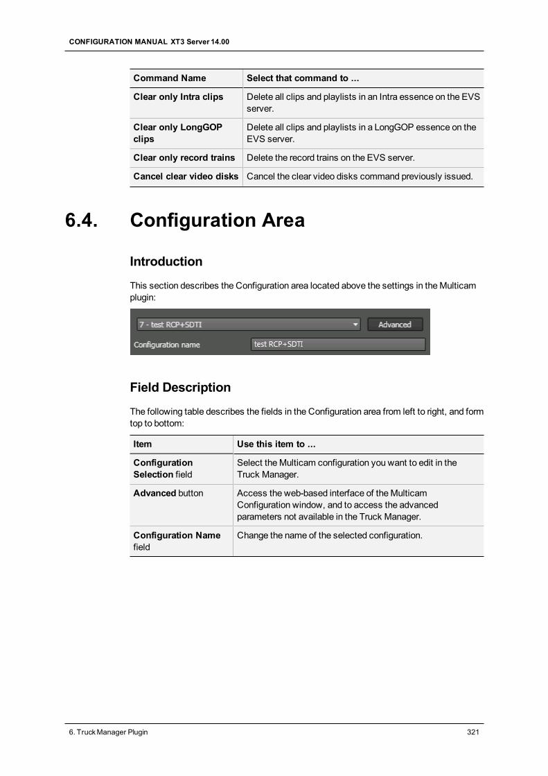
Command Name Select that command to ...
Clear only Intra clips Delete all clips and playlists in an Intra essence on the EVSserver.
Clear only LongGOPclips
Delete all clips and playlists in a LongGOP essence on theEVS server.
Clear only record trains Delete the record trains on the EVS server.
Cancel clear video disks Cancel the clear video disks command previously issued.
6.4. Configuration Area
Introduction
This section describes the Configuration area located above the settings in theMulticamplugin:
Field Description
The following table describes the fields in the Configuration area from left to right, and formtop to bottom:
Item Use this item to ...
ConfigurationSelection field
Select theMulticam configuration you want to edit in theTruck Manager.
Advanced button Access the web-based interface of theMulticamConfiguration window, and to access the advancedparameters not available in the Truck Manager.
Configuration Namefield
Change the name of the selected configuration.
CONFIGURATION MANUAL XT3 Server 14.00
6. TruckManager Plugin 321
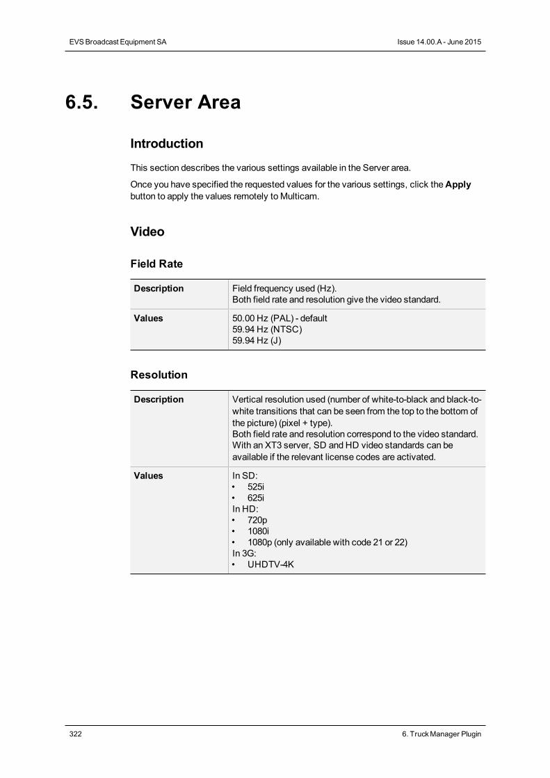
6.5. Server Area
Introduction
This section describes the various settings available in the Server area.
Once you have specified the requested values for the various settings, click theApplybutton to apply the values remotely to Multicam.
Video
Field Rate
Description Field frequency used (Hz).Both field rate and resolution give the video standard.
Values 50.00 Hz (PAL) - default59.94 Hz (NTSC)59.94 Hz (J)
Resolution
Description Vertical resolution used (number of white-to-black and black-to-white transitions that can be seen from the top to the bottom ofthe picture) (pixel + type).Both field rate and resolution correspond to the video standard.With an XT3 server, SD and HD video standards can beavailable if the relevant license codes are activated.
Values In SD:• 525i• 625iIn HD:• 720p• 1080i• 1080p (only available with code 21 or 22)In 3G:• UHDTV-4K
322 6. TruckManager Plugin
EVSBroadcast Equipment SA Issue 14.00.A - June 2015
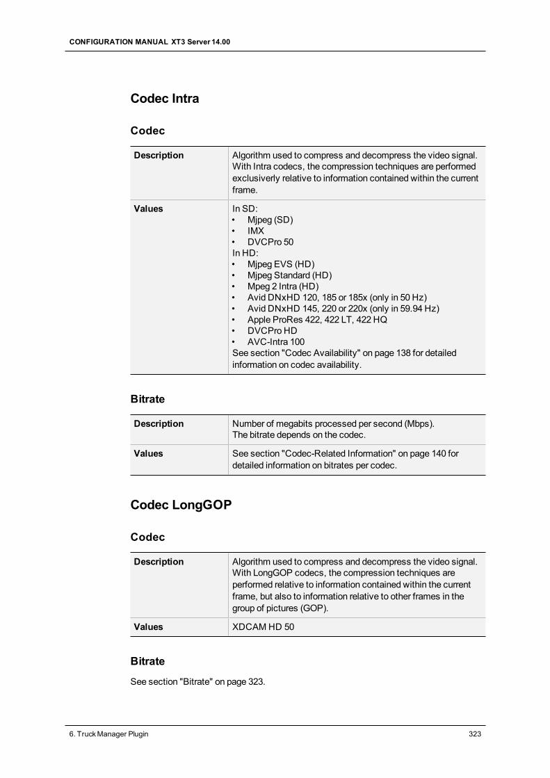
Codec Intra
Codec
Description Algorithm used to compress and decompress the video signal.With Intra codecs, the compression techniques are performedexclusiverly relative to information contained within the currentframe.
Values In SD:• Mjpeg (SD)• IMX• DVCPro 50In HD:• Mjpeg EVS (HD)• Mjpeg Standard (HD)• Mpeg 2 Intra (HD)• Avid DNxHD 120, 185 or 185x (only in 50 Hz)• Avid DNxHD 145, 220 or 220x (only in 59.94 Hz)• Apple ProRes 422, 422 LT, 422 HQ• DVCPro HD• AVC-Intra 100See section "Codec Availability" on page 138 for detailedinformation on codec availability.
Bitrate
Description Number of megabits processed per second (Mbps).The bitrate depends on the codec.
Values See section "Codec-Related Information" on page 140 fordetailed information on bitrates per codec.
Codec LongGOP
Codec
Description Algorithm used to compress and decompress the video signal.With LongGOP codecs, the compression techniques areperformed relative to information contained within the currentframe, but also to information relative to other frames in thegroup of pictures (GOP).
Values XDCAMHD 50
Bitrate
See section "Bitrate" on page 323.
CONFIGURATION MANUAL XT3 Server 14.00
6. TruckManager Plugin 323
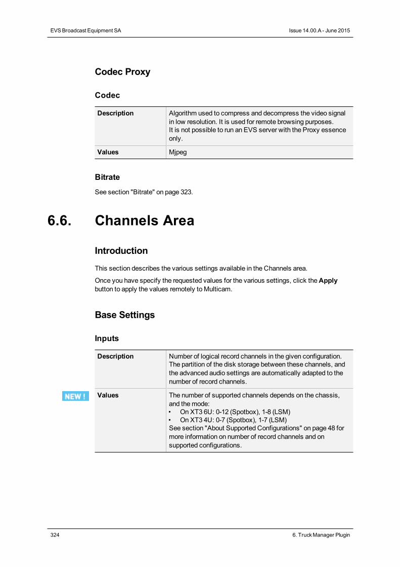
Codec Proxy
Codec
Description Algorithm used to compress and decompress the video signalin low resolution. It is used for remote browsing purposes.It is not possible to run an EVS server with the Proxy essenceonly.
Values Mjpeg
Bitrate
See section "Bitrate" on page 323.
6.6. Channels Area
Introduction
This section describes the various settings available in the Channels area.
Once you have specify the requested values for the various settings, click theApplybutton to apply the values remotely to Multicam.
Base Settings
Inputs
Description Number of logical record channels in the given configuration.The partition of the disk storage between these channels, andthe advanced audio settings are automatically adapted to thenumber of record channels.
Values The number of supported channels depends on the chassis,and themode:• On XT3 6U: 0-12 (Spotbox), 1-8 (LSM)• On XT3 4U: 0-7 (Spotbox), 1-7 (LSM)See section "About Supported Configurations" on page 48 formore information on number of record channels and onsupported configurations.
324 6. TruckManager Plugin
EVSBroadcast Equipment SA Issue 14.00.A - June 2015
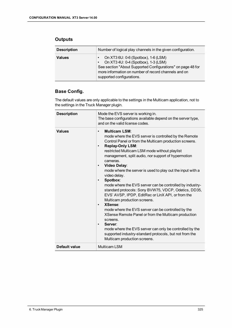
Outputs
Description Number of logical play channels in the given configuration.
Values • On XT3 6U: 0-6 (Spotbox), 1-6 (LSM)• On XT3 4U: 0-4 (Spotbox), 1-3 (LSM)See section "About Supported Configurations" on page 48 formore information on number of record channels and onsupported configurations.
Base Config.
The default values are only applicable to the settings in theMulticam application, not tothe settings in the Truck Manager plugin.
Description Mode the EVS server is working in.The base configurations available depend on the server type,and on the valid license codes.
Values • Multicam LSM:mode where the EVS server is controlled by the RemoteControl Panel or from theMulticam production screens.
• Replay-Only LSM:restrictedMulticam LSMmodewithout playlistmanagement, split audio, nor support of hypermotioncameras.
• Video Delay:mode where the server is used to play out the input with avideo delay.
• Spotbox:mode where the EVS server can be controlled by industry-standard protocols: Sony BVW75, VDCP, Odetics, DD35,EVS’ AVSP, IPDP, EditRec or LinX API, or from theMulticam production screens.
• XSense:mode where the EVS server can be controlled by theXSense Remote Panel or from theMulticam productionscreens.
• Server:mode where the EVS server can only be controlled by thesupported industry-standard protocols, but not from theMulticam production screens.
Default value Multicam LSM
CONFIGURATION MANUAL XT3 Server 14.00
6. TruckManager Plugin 325
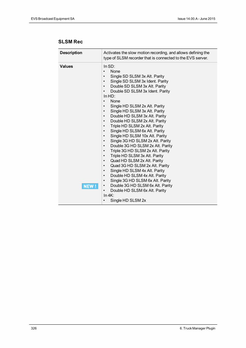
SLSM Rec
Description Activates the slow motion recording, and allows defining thetype of SLSM recorder that is connected to the EVS server.
Values In SD:• None• Single SD SLSM 3x Alt. Parity• Single SD SLSM 3x Ident. Parity• Double SD SLSM 3x Alt. Parity• Double SD SLSM 3x Ident. ParityIn HD:• None• Single HD SLSM 2x Alt. Parity• Single HD SLSM 3x Alt. Parity• Double HD SLSM 3x Alt. Parity• Double HD SLSM 2x Alt. Parity• Triple HD SLSM 2x Alt. Parity• Single HD SLSM 6x Alt. Parity• Single HD SLSM 10x Alt. Parity• Single 3GHD SLSM 2x Alt. Parity• Double 3GHD SLSM 2x Alt. Parity• Triple 3GHD SLSM 2x Alt. Parity• Triple HD SLSM 3x Alt. Parity• Quad HD SLSM 2x Alt. Parity• Quad 3GHD SLSM 2x Alt. Parity• Single HD SLSM 4x Alt. Parity• Double HD SLSM 4x Alt. Parity• Single 3GHD SLSM 6x Alt. Parity• Double 3GHD SLSM 6x Alt. Parity• Double HD SLSM 6x Alt. ParityIn 4K:• Single HD SLSM 2x
326 6. TruckManager Plugin
EVSBroadcast Equipment SA Issue 14.00.A - June 2015
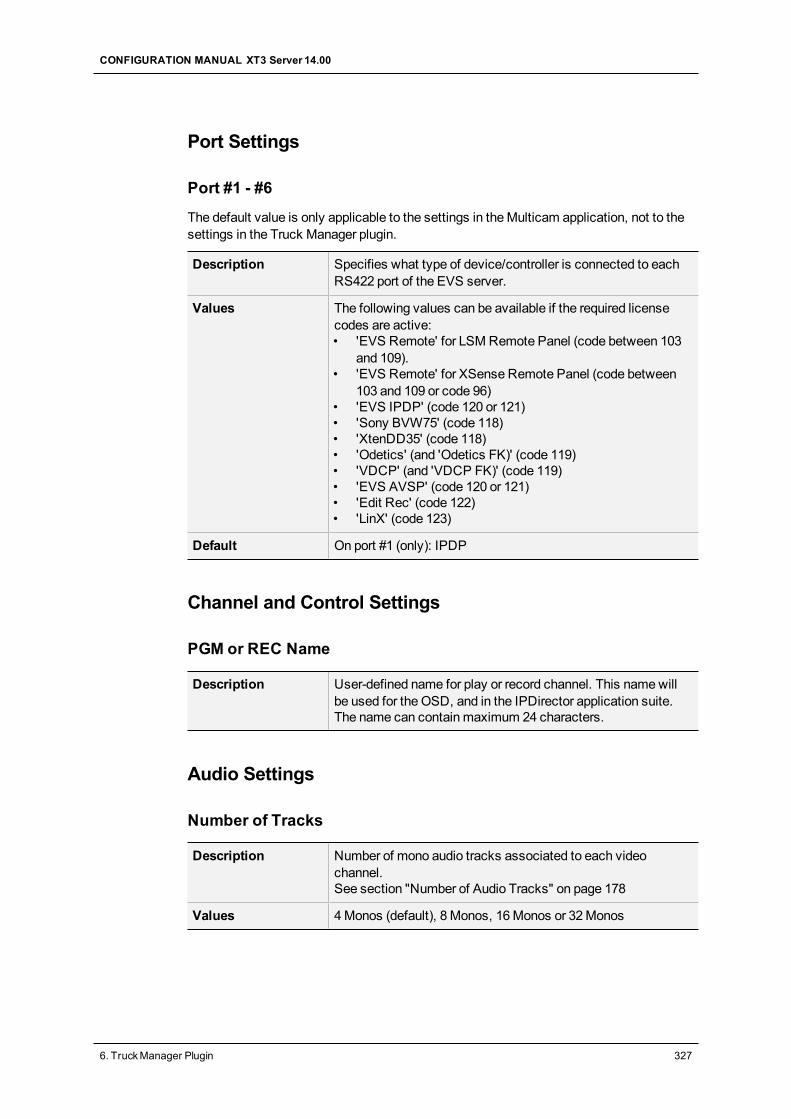
Port Settings
Port #1 - #6
The default value is only applicable to the settings in theMulticam application, not to thesettings in the Truck Manager plugin.
Description Specifies what type of device/controller is connected to eachRS422 port of the EVS server.
Values The following values can be available if the required licensecodes are active:• 'EVS Remote' for LSM Remote Panel (code between 103
and 109).• 'EVS Remote' for XSense Remote Panel (code between
103 and 109 or code 96)• 'EVS IPDP' (code 120 or 121)• 'Sony BVW75' (code 118)• 'XtenDD35' (code 118)• 'Odetics' (and 'Odetics FK)' (code 119)• 'VDCP' (and 'VDCP FK)' (code 119)• 'EVS AVSP' (code 120 or 121)• 'Edit Rec' (code 122)• 'LinX' (code 123)
Default On port #1 (only): IPDP
Channel and Control Settings
PGM or REC Name
Description User-defined name for play or record channel. This namewillbe used for the OSD, and in the IPDirector application suite.The name can contain maximum 24 characters.
Audio Settings
Number of Tracks
Description Number of mono audio tracks associated to each videochannel.See section "Number of Audio Tracks" on page 178
Values 4Monos (default), 8 Monos, 16Monos or 32Monos
CONFIGURATION MANUAL XT3 Server 14.00
6. TruckManager Plugin 327
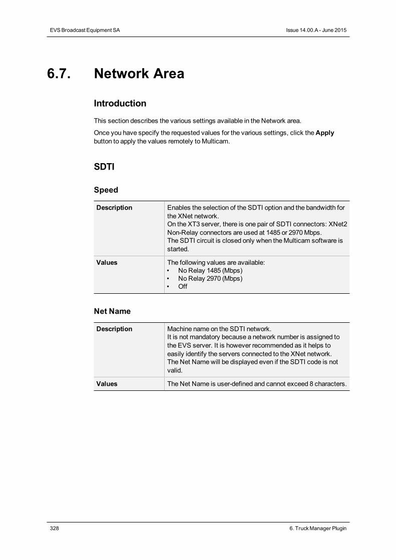
6.7. Network Area
Introduction
This section describes the various settings available in the Network area.
Once you have specify the requested values for the various settings, click theApplybutton to apply the values remotely to Multicam.
SDTI
Speed
Description Enables the selection of the SDTI option and the bandwidth forthe XNet network.On the XT3 server, there is one pair of SDTI connectors: XNet2Non-Relay connectors are used at 1485 or 2970Mbps.The SDTI circuit is closed only when theMulticam software isstarted.
Values The following values are available:• No Relay 1485 (Mbps)• No Relay 2970 (Mbps)• Off
Net Name
Description Machine name on the SDTI network.It is not mandatory because a network number is assigned tothe EVS server. It is however recommended as it helps toeasily identify the servers connected to the XNet network.The Net Namewill be displayed even if the SDTI code is notvalid.
Values The Net Name is user-defined and cannot exceed 8 characters.
328 6. TruckManager Plugin
EVSBroadcast Equipment SA Issue 14.00.A - June 2015
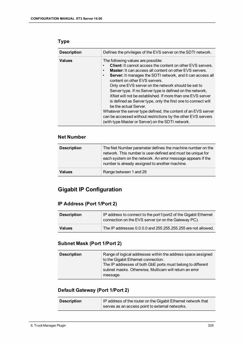
Type
Description Defines the privileges of the EVS server on the SDTI network.
Values The following values are possible:• Client: It cannot access the content on other EVS servers.• Master: It can access all content on other EVS servers.• Server: It manages the SDTI network, and it can access all
content on other EVS servers.Only one EVS server on the network should be set toServer type. If no Server type is defined on the network,XNet will not be established. If more than one EVS serveris defined as Server type, only the first one to connect willbe the actual Server.
Whatever the server type defined, the content of an EVS servercan be accessed without restrictions by the other EVS servers(with typeMaster or Server) on the SDTI network.
Net Number
Description The Net Number parameter defines themachine number on thenetwork. This number is user-defined andmust be unique foreach system on the network. An error message appears if thenumber is already assigned to another machine.
Values Range between 1 and 29
Gigabit IP Configuration
IP Address (Port 1/Port 2)
Description IP address to connect to the port1/port2 of the Gigabit Ethernetconnection on the EVS server (or on the Gateway PC).
Values The IP addresses 0.0.0.0 and 255.255.255.255 are not allowed.
Subnet Mask (Port 1/Port 2)
Description Range of logical addresses within the address space assignedto the Gigabit Ethernet connection.The IP addresses of both GbE ports must belong to differentsubnet masks. Otherwise, Multicam will return an errormessage.
Default Gateway (Port 1/Port 2)
Description IP address of the router on the Gigabit Ethernet network thatserves as an access point to external networks.
CONFIGURATION MANUAL XT3 Server 14.00
6. TruckManager Plugin 329

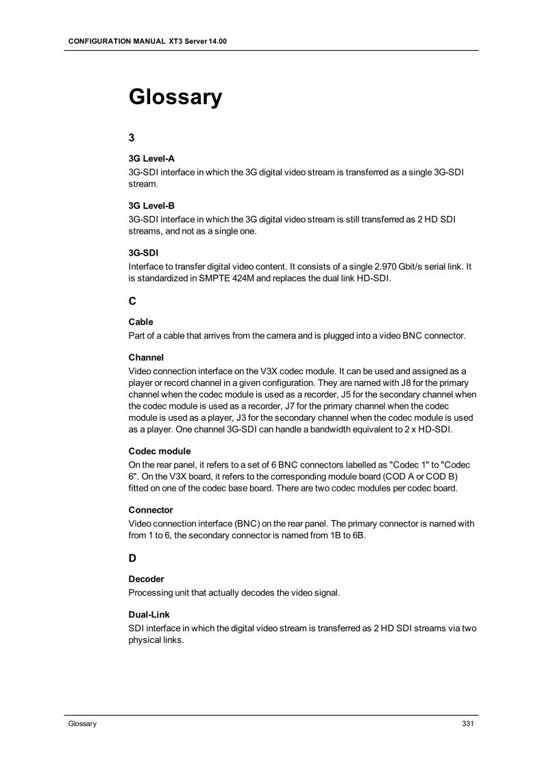
Glossary3
3G Level-A3G-SDI interface in which the 3G digital video stream is transferred as a single 3G-SDIstream.
3G Level-B3G-SDI interface in which the 3G digital video stream is still transferred as 2 HD SDIstreams, and not as a single one.
3G-SDIInterface to transfer digital video content. It consists of a single 2.970Gbit/s serial link. Itis standardized in SMPTE 424M and replaces the dual link HD-SDI.
C
CablePart of a cable that arrives from the camera and is plugged into a video BNC connector.
ChannelVideo connection interface on the V3X codec module. It can be used and assigned as aplayer or record channel in a given configuration. They are namedwith J8 for the primarychannel when the codec module is used as a recorder, J5 for the secondary channel whenthe codec module is used as a recorder, J7 for the primary channel when the codecmodule is used as a player, J3 for the secondary channel when the codec module is usedas a player. One channel 3G-SDI can handle a bandwidth equivalent to 2 x HD-SDI.
Codec moduleOn the rear panel, it refers to a set of 6 BNC connectors labelled as "Codec 1" to "Codec6". On the V3X board, it refers to the correspondingmodule board (COD A or COD B)fitted on one of the codec base board. There are two codec modules per codec board.
ConnectorVideo connection interface (BNC) on the rear panel. The primary connector is namedwithfrom 1 to 6, the secondary connector is named from 1B to 6B.
D
DecoderProcessing unit that actually decodes the video signal.
Dual-LinkSDI interface in which the digital video stream is transferred as 2 HD SDI streams via twophysical links.
CONFIGURATION MANUAL XT3 Server 14.00
Glossary 331
E
EncoderProcessing unit that actually encodes the video signal.
Extended ConfigurationsThis feature allows using the secondary channel of the codec module as an independentrecord channel. With an XT3 server, the possible extendedmodes are the 7-channel modewith the 4U chassis, and the 8- and 12-channel mode with the 6U chassis.
G
GPIAbbreviation for General Purpose Interface. This refers to a device used as ancommunication interface with the EVS server. It has digital lines whichmay be used forinput, output, or both, depending on the function.
H
Hypermotion cameraThese are cameras that record at a frame ratemuch higher than real time. The contentrecorded at high frame rate on amemory block of the camera buffer is ingested into theEVS server through a single record channel when the operator initiates a play commandon the camera. Hypermotion cameras can be controlled by an LSM Remote Panel.
I
Intra-frame codecCodec type for which the compression techniques are performed relative to informationcontained within the current frame, and not relative to any other frame in the videosequence. It is shortened by 'intra' in themanual.This is opposed to long-GOP codecs.(SourceWikipedia)
L
Logical channelLogical player or recorder channel in a given configuration, independent from the physicalconnections that have to be used to enable this logical channel.
M
Mix on One ChannelFeature that allows using the secondary link of the codec module of a player channel onthe V3X board (J3) as the preview channel to provide the PGM/PRV modewith a singlecodec module.
Multicam Configuration windowWindow in the server-based and web-basedMulticam Setup application from where youcan define all configuration parameters.
332 Glossary
EVSBroadcast Equipment SA Issue 14.00.A - June 2015
Multicam Setup applicationTerm used to refer equally to the server-based or web-based user interface used to set upand configure the EVS servers.
Multicam Setup windowInitial Window in the server-based and web-basedMulticam Setup application, that isdisplayed when the EVS server is not running a given configuration yet. It gives access tothe configuration lines defined on the EVS server and to the commonly usedmaintenancetools.
Multi-Essence configurationEVS server configuration that allows multiple and simultaneous encoding of the videomateral into the server. Intra+ XDCAM is an example of amulti-essence configuration.
O
Operational Setup menuMenu accessible on the Remote Panel using the SHIFT+D keys form themainmenu. Itallows users to define operational parameters.
OSDAbbreviation for on-screen display.
P
Physical channelSee also Channel.
Play channel (or Player)Codec module used as a player.
R
Record channel (or Recorder)Codec module used as a recorder.
S
SDTI networkEVS proprietary network that allows users to view and share the content of interconnectedEVS video servers. 'XNet network' is used as synonym for 'SDTI network'.
Server-Based Multicam Setup applicationServer-Based application used to set up and configure the EVS servers. The short form is'Server-Based application' in this user manual. This is accessible from the EVS Serveritself when it has been started.
SLSM cameraAlso called Supermotion cameras. These are cameras that record at a frame rate 2, 3, 4 or6 times higher than the normal frame rate of 25 fps (PAL) or 30 fps (NTSC). The 2, 3, 4 or 6phases of the camera are ingested in parallel as separate record channels into the EVSserver.
CONFIGURATION MANUAL XT3 Server 14.00
Glossary 333
T
Technical Setup menuMenu accessible on the Remote Panel using the F0 key. It allows users to define currentlyused configuration parameters.
U
U-Motion camerasAlso called Ultramotion cameras. These are cameras that record at a frame rate ten timeshigher than the normal frame rate of 25 fps (PAL) or 30 fps (NTSC). The ten phases of thecamera are ingested in parallel as separate record channels into the EVS server.
W
Web-Based Multicam Setup interfaceWeb-Based interface used to set up and configure the EVS servers. The short form is'web-based interface' in this manual. This is accessible from any machine (PC or server)that is on the same network range as the EVS server. This can be accessed from awebbrowser using the following URL pattern: http://xxx.xxx.xxx.xxx/cfgweb/ where thecrosses correspond to the IP address of the PC LAN of the EVS server.
334 Glossary
EVSBroadcast Equipment SA Issue 14.00.A - June 2015