Embed Size (px)
Citation preview
Policy ManagementConfiguration Management Platform
Wireless User's Guide910-6402-001 Revision A
June 2012
Copyright 2012 Tekelec. All Rights Reserved. Printed in USA.Legal Information can be accessed from the Main Menu of the optical disc or on the
Tekelec Customer Support web site in the Legal Information folder of the Product Support tab.

Table of Contents
Chapter 1: About This Guide...........................................................14Introduction.............................................................................................................................15How This Guide is Organized...............................................................................................15Scope and Audience...............................................................................................................16Documentation Admonishments..........................................................................................16Customer Care Center............................................................................................................17Emergency Response..............................................................................................................19Related Publications...............................................................................................................19Locate Product Documentation on the Customer Support Site.......................................21
Chapter 2: The Multimedia Policy Engine....................................22The Multimedia Policy Engine..............................................................................................23Understanding Policy Rules..................................................................................................23Overview of Major Tasks.......................................................................................................23The Configuration Management Platform..........................................................................25
Organizing Policy Rules.............................................................................................25GUI Overview..............................................................................................................25Specifications for Using the GUI ..............................................................................26GUI Icons......................................................................................................................27Shortcut Selection Keys..............................................................................................27Changing a Password.................................................................................................27
Chapter 3: Configuring the Policy Management Topology.......29About the Policy Management Topology............................................................................30
High Availability.........................................................................................................30MPE and MRA Georedundancy...............................................................................31CMP Georedundancy.................................................................................................33Primary and Secondary Sites.....................................................................................34Cluster Preferences.....................................................................................................34Server Status................................................................................................................35
Setting Up the Topology........................................................................................................35Setting Up a CMP Cluster..........................................................................................36Setting Up a Site..........................................................................................................38Setting Up an MPE Cluster........................................................................................38
ii910-6402-001 Revision A, June 2012

Modifying the Topology........................................................................................................40Modifying a Site..........................................................................................................41Removing a Site from the Topology.........................................................................41Modifying an MPE or MRA Cluster.........................................................................41Modifying a CMP Cluster..........................................................................................42Removing a Cluster from the Topology..................................................................43Reversing Cluster Preference....................................................................................43Demoting a CMP Cluster...........................................................................................43Forcing a Server into Standby Status.......................................................................45
Configuring SNMP Settings..................................................................................................45Defining Global Configuration Settings..............................................................................48
Setting the Precedence Range....................................................................................48Setting UE-Initiated Procedures................................................................................49Setting Stats Settings...................................................................................................49Setting Quota Settings................................................................................................50
Chapter 4: Managing MPE Devices................................................52Policy Server Profiles..............................................................................................................53
Creating a Policy Server Profile................................................................................53Configuring or Modifying a Policy Server Profile.................................................54Deleting a Policy Server Profile.................................................................................54
Configuring Protocol Options on the Policy Server...........................................................55Configuring MPE Advanced Settings..................................................................................62Configuring Data Source Interfaces.....................................................................................64
Configuring an LDAP Data Source..........................................................................65Configuring an Sh Data Source.................................................................................70
Policy Server Groups..............................................................................................................74Creating a Policy Server Group................................................................................75Adding a Policy Server to a Policy Server Group .................................................75Creating a Policy Server Sub-group.........................................................................76Renaming a Policy Server Group..............................................................................76Removing a Policy Server Profile from a Policy Server Group............................76Deleting a Policy Server Group.................................................................................77
Reapplying the Configuration to a Policy Server...............................................................77Checking the Status of an MPE Server.................................................................................78Policy Server Reports..............................................................................................................79
Cluster Information Report.......................................................................................80Time Period..................................................................................................................80Policy Statistics............................................................................................................81Protocol Statistics........................................................................................................81
iii910-6402-001 Revision A, June 2012

Error Statistics..............................................................................................................82Data Source Statistics..................................................................................................83Database Statistics.......................................................................................................84Interval Statistics.........................................................................................................84
Policy Server Logs...................................................................................................................85The Trace Log..............................................................................................................86Syslog Support.............................................................................................................88The SMPP Log.............................................................................................................88The SMTP Log.............................................................................................................88Configuring Log Settings...........................................................................................88
Chapter 5: Configuring Protocol Routing......................................91Configuring Diameter Peers..................................................................................................92Configuring Diameter Routes...............................................................................................93
Chapter 6: Managing Network Elements.......................................96About Network Elements......................................................................................................97Defining a Network Element.................................................................................................97
Modifying a Network Element.................................................................................98Deleting Network Elements......................................................................................98Bulk Delete...................................................................................................................99Finding a Network Element......................................................................................99
Configuring Options for Network Elements....................................................................100PDSN...........................................................................................................................100Home Agent...............................................................................................................101GGSN..........................................................................................................................101HSGW.........................................................................................................................102PGW............................................................................................................................102SGW.............................................................................................................................102DPI...............................................................................................................................103NAS.............................................................................................................................104
Associating a Network Element with an MPE Device....................................................104Working with Network Element Groups..........................................................................105
Creating a Network Element Group......................................................................105Adding a Network Element to a Network Element Group................................106Creating a Network Element Sub-group...............................................................107Deleting a Network Element from a Network Element Group.........................108Modifying a Network Element Group...................................................................108Deleting a Network Element Group or Sub-group..............................................108
iv910-6402-001 Revision A, June 2012

Chapter 7: Managing Application Profiles..................................110About Application Profiles..................................................................................................111Creating an Application Profile..........................................................................................111Modifying an Application Profile.......................................................................................112Deleting an Application Profile..........................................................................................112
Chapter 8: Managing Match Lists..................................................113Creating a Match List............................................................................................................114Modifying a Match List........................................................................................................115Deleting a Match List............................................................................................................115
Chapter 9: Managing Quotas..........................................................116Creating a Quota Profile.......................................................................................................117Modifying a Quota................................................................................................................120Deleting a Quota....................................................................................................................120Adding a Member to a Pooled Quota Group....................................................................120Querying by Pool ID.............................................................................................................121Creating a Pool Quota Profile..............................................................................................122Modifying a Pool Quota Profile..........................................................................................122Deleting a Pool Quota Profile..............................................................................................123Modifying a Pool Profile......................................................................................................123Deleting a Pool Profile..........................................................................................................124Creating a Pool State.............................................................................................................124Modifying a Pool State.........................................................................................................125Deleting a Pool State.............................................................................................................125
Chapter 10: Managing Services and Rating Groups..................126Creating a Service..................................................................................................................127Modifying a Service..............................................................................................................127Deleting a Service..................................................................................................................128About Rating Groups...........................................................................................................128
Creating a Rating Group..........................................................................................128Adding a Service to a Rating Group......................................................................129Modifying a Rating Group......................................................................................129Removing a Service from a Rating Group.............................................................129Deleting a Rating Group..........................................................................................130
v910-6402-001 Revision A, June 2012

Chapter 11: Managing Traffic Profiles.........................................131About Traffic Profiles...........................................................................................................132Creating a Traffic Profile......................................................................................................132Modifying a Traffic Profile..................................................................................................138Deleting a Traffic Profile......................................................................................................138Traffic Profile Groups...........................................................................................................139
Creating a Traffic Profile Group.............................................................................139Adding a Traffic Profile to a Traffic Profile Group..............................................139Modifying a Traffic Profile Group..........................................................................140Removing a Traffic Profile from a Traffic Profile Group....................................141Deleting a Traffic Profile Group..............................................................................141
Chapter 12: Managing Retry Profiles............................................143About Retry Profiles.............................................................................................................144Creating a Retry Profile........................................................................................................144Modifying a Retry Profile....................................................................................................145Deleting a Retry Profile........................................................................................................146
Chapter 13: Managing Charging Servers.....................................147About Charging Servers.......................................................................................................148Defining a Charging Server.................................................................................................148Modifying a Charging Server..............................................................................................149Deleting a Charging Server..................................................................................................149Associating a Charging Server with an MPE Device.......................................................150
Chapter 14: Managing Policy Time Periods................................151About Policy Time Periods..................................................................................................152Creating a Time Period.........................................................................................................152Deleting a Time Period.........................................................................................................153Time-of-Day Triggers...........................................................................................................153
Chapter 15: Managing Serving Gateways to MCCs/MNCs.....154About Mapping Serving Gateways to MCCs/MNCs.....................................................155Creating a Mapping..............................................................................................................155Modifying a Mapping...........................................................................................................155Deleting a Mapping..............................................................................................................156
vi910-6402-001 Revision A, June 2012

Chapter 16: Managing Monitoring Keys......................................157About Monitoring Keys.......................................................................................................158Creating a Monitoring Key..................................................................................................158Modifying a Monitoring Key...............................................................................................159Deleting a Monitoring Key..................................................................................................159
Chapter 17: Managing Third-Party AVPs....................................160About AVPs...........................................................................................................................161Creating an AVP....................................................................................................................162Modifying an AVP................................................................................................................165Deleting an AVP ...................................................................................................................165
Chapter 18: Managing Multi-Protocol Routing Agents............166Configuring the CMP to Manage an MRA Cluster..........................................................167Defining an MRA Cluster Profile........................................................................................167Modifying an MRA Cluster Profile....................................................................................168Working with MRA Groups................................................................................................168
Creating an MRA Group..........................................................................................168Adding an MRA Cluster Profile to an MRA Group............................................169Deleting an MRA Cluster Profile from an MRA Group......................................169Deleting an MRA Group..........................................................................................169Enabling Stateless Routing......................................................................................170
Chapter 19: Managing Subscriber Profile Repositories............171About Subscriber Profile Repositories...............................................................................172Configuring the CMP to Manage SPR Subscriber Data..................................................172Configuring the SPR Connection........................................................................................173Modifying the SPR Connection...........................................................................................173Finding a Subscriber Profile................................................................................................174Creating a Subscriber Profile...............................................................................................174Modifying a Subscriber Profile...........................................................................................176Deleting a Subscriber Profile...............................................................................................176Viewing Subscriber Entity States........................................................................................176Creating a Subscriber Entity State Property......................................................................177Modifying a Subscriber Entity State Property..................................................................177Deleting a Subscriber Entity State Property......................................................................178Viewing Subscriber Quota Information.............................................................................178Adding a Subscriber Quota Category................................................................................180
vii910-6402-001 Revision A, June 2012

Modifying a Subscriber Quota Category...........................................................................181Deleting a Subscriber Quota Category...............................................................................181
Chapter 20: Understanding and Creating Policy Rules............183Structure and Evaluation of Policy Rules..........................................................................184
Structure of Policy Rules..........................................................................................184Evaluating Policy Rules............................................................................................186Activating and Deactivating Policy Rules.............................................................187Using Reference Policies..........................................................................................188
Creating a New Policy..........................................................................................................189Modes Within the Policy Wizard........................................................................................193Parameters Within Policy Rules..........................................................................................194Conditions Available for Writing Policy Rules................................................................196
Request Conditions...................................................................................................197Application Conditions............................................................................................213Network Device Identity Conditions.....................................................................214Network Device Usage Conditions........................................................................216Mobility Conditions..................................................................................................218User Conditions.........................................................................................................222User State Conditions...............................................................................................231Policy Context Properties.........................................................................................235Time-of-Day Conditions..........................................................................................235
Actions Available for Writing Policy Rules......................................................................237Mandatory Policy-Processing Actions ..................................................................238Optional Actions.......................................................................................................238
Policy Rule Variables............................................................................................................271Using Policy Rule Variables....................................................................................271Basic Policy Rule Variables......................................................................................271
Chapter 21: Managing Policy Rules..............................................279Displaying a Policy...............................................................................................................280Deploying Policy Rules........................................................................................................281Modifying and Deleting a Policy........................................................................................283
Modifying a Policy....................................................................................................283Deleting a Policy........................................................................................................284
Policy Templates...................................................................................................................284Creating a Policy Template......................................................................................285Modifying a Policy Template..................................................................................286Deleting a Policy Template......................................................................................286
Managing a Policy Group....................................................................................................287
viii910-6402-001 Revision A, June 2012

Creating a Policy Group...........................................................................................287Adding a Policy to a Policy Group.........................................................................288Removing a Policy from a Policy Group...............................................................290Changing the Sequence of Policies Within a Policy Group................................291Displaying Policy Details Contained Within a Policy Group.............................291Deploying a Policy or Policy Group to MPE Devices..........................................291Removing a Policy from a Policy Group on an MPE Device..............................292Removing a Policy or Policy Group from an MPE Device.................................293Changing the Sequence of Deployed Policy Groups...........................................294
Importing and Exporting Policies, Policy Groups, and Templates...............................294Importing Policies.....................................................................................................294Exporting Policies.....................................................................................................295
Managing Policy Checkpoints.............................................................................................295Viewing and Comparing Policy Checkpoints.......................................................296Creating a Policy Checkpoint..................................................................................296Restoring a Policy Checkpoint................................................................................297Restoring a Policy Checkpoint to MPEs................................................................297Deleting a Policy Checkpoint..................................................................................298
Chapter 22: Managing Policy Tables............................................299About Policy Tables..............................................................................................................300Creating Policy Tables..........................................................................................................300Modifying Policy Tables......................................................................................................301Deleting Policy Tables..........................................................................................................301Viewing Policy Tables..........................................................................................................302
Chapter 23: Managing Subscribers...............................................303Creating a Tier.......................................................................................................................304Deleting a Tier.......................................................................................................................304Managing Sessions................................................................................................................305
Chapter 24: System-Wide Reports.................................................307Viewing Active Alarms........................................................................................................308Viewing the Alarm History Report....................................................................................309KPI Dashboard......................................................................................................................310
Mapping Display to KPIs.........................................................................................312Mapping Reports Display to KPIs..........................................................................315Color Threshold Configuration...............................................................................331
Viewing the Trending Reports............................................................................................332
ix910-6402-001 Revision A, June 2012

Viewing the PDN Connection Count.....................................................................332Viewing the Session Count......................................................................................333Viewing MRA Binding Count.................................................................................333Viewing Transactions Per Second..........................................................................334
Viewing the Connection Status Report..............................................................................335Viewing the Protocol Errors Report...................................................................................336Viewing the Policy Statistics Report...................................................................................337
Chapter 25: Upgrade Manager.......................................................338Upgrade Manager Elements................................................................................................339
Chapter 26: System Administration..............................................341Configuring System Settings...............................................................................................342Importing to and Exporting from the CMP Database ....................................................344
Using the OSSI XML Interface.................................................................................344Importing an XML File to Input Objects................................................................345Exporting an XML File.............................................................................................346
The Manager Report.............................................................................................................346The Trace Log........................................................................................................................347Modifying the Trace Log Configuration............................................................................348Viewing the Audit Log.........................................................................................................348
Searching for Audit Log Entries.............................................................................350Exporting or Purging Audit Log Data...................................................................350
Managing Scheduled Tasks.................................................................................................351Configuring a Task................................................................................................................352User Management.................................................................................................................354
Configuring Roles.....................................................................................................354Creating a New Role.................................................................................................354Modifying a Role.......................................................................................................356Deleting a Role...........................................................................................................357Creating a New Scope..............................................................................................357Modifying a Scope....................................................................................................358Deleting a Scope........................................................................................................358Creating a User Profile.............................................................................................359Modifying a User Profile..........................................................................................360Deleting a User Profile.............................................................................................361Locking and Unlocking User Accounts.................................................................362
Changing a Password...........................................................................................................363RADIUS Authentication and Accounting.........................................................................363
Configuring the RADIUS Server.............................................................................364
x910-6402-001 Revision A, June 2012

Associating Roles and Scopes..................................................................................365Enabling RADIUS on the CMP System.................................................................366
SANE Authentication...........................................................................................................368Enabling SANE Authentication on the CMP System......................................................369Creating a Customer User Management System Profile.................................................370
Appendix A: CMP Modes...............................................................371The Mode Settings Page.......................................................................................................372
Glossary..................................................................................................................376
xi910-6402-001 Revision A, June 2012

List of FiguresFigure 1: Structure of the CMP GUI ................................................................................................26Figure 2: Policy Management Topology..........................................................................................30Figure 3: High Availability................................................................................................................31Figure 4: MPE or MRA Cluster with Active, Standby, and Spare Servers.................................32Figure 5: MPE or MRA Georedundant Configuration..................................................................33Figure 6: CMP Georedundancy.........................................................................................................34Figure 7: Cluster Settings Page for CMP Cluster............................................................................37Figure 8: Cluster Settings Page for MPE Cluster............................................................................40Figure 9: Group View ........................................................................................................................79Figure 10: Sample Protocol Statistics................................................................................................81Figure 11: Sample Error Statistics.....................................................................................................83Figure 12: SPR Data Source Statistics...............................................................................................84Figure 13: Policy Server Logs Tab.....................................................................................................86Figure 14: Add Network Element Page.........................................................................................107Figure 15: New Quota Page.............................................................................................................119Figure 16: Add Traffic Profile Page................................................................................................140Figure 17: New Retry Profile Page..................................................................................................145Figure 18: Enabling Stateless Routing............................................................................................170Figure 19: Subscriber Profile Quota Usage Page..........................................................................179Figure 20: Sample Policy Description............................................................................................280Figure 21: Policy Deployment.........................................................................................................281Figure 22: Policy Group Deployment.............................................................................................282Figure 23: Policy Redeployment.....................................................................................................283Figure 24: Create New Template Window....................................................................................285Figure 25: Modify Policy Template Window................................................................................286Figure 26: Session Viewer Page.......................................................................................................306Figure 27: Sample Active Alarms Report......................................................................................308Figure 28: Example of KPI Dashboard with MRAs Managed by the CMP..............................311Figure 29: Sample Connection Status Report................................................................................335Figure 30: Sample Password Strength Policy................................................................................344Figure 31: Audit Log.........................................................................................................................349Figure 32: Audit Log Details............................................................................................................349Figure 33: Deleting a Scope..............................................................................................................359Figure 34: Modify User Page...........................................................................................................361Figure 35: Tekelec VSA Dictionary For RADIUS.........................................................................364Figure 36: External Authentication Configuration Page.............................................................368Figure 37: Mode Settings Page........................................................................................................373
xii910-6402-001 Revision A, June 2012

List of TablesTable 1: Admonishments...................................................................................................................16Table 2: SNMP Attributes..................................................................................................................46Table 3: Policy Server Protocol Configuration Options.................................................................55Table 4: Session Clean Up Options...................................................................................................63Table 5: Traffic Profile Type Configuration Parameters..............................................................133Table 6: Common Parameters.........................................................................................................194Table 7: Policy Condition Categories.............................................................................................196Table 8: Basic Policy Rule Variables...............................................................................................272Table 9: ChargingRuleInstall OnNet..............................................................................................300Table 10: ChargingRuleInstall OffNet............................................................................................300Table 11: KPI Definitions for MRA.................................................................................................312Table 12: KPI Definitions for MPE when MRAs are Managed by CMP...................................314Table 13: KPI Definitions for MPE when MRAs are not Managed by CMP............................315Table 14: Diameter Application Function (AF) Stats...................................................................316Table 15: Diameter Policy Charging Enforcement Function (PCEF) Statistics........................318Table 16: Diameter Charging Function (CTF) Statistics..............................................................319Table 17: Diameter Bearer Binding and Event Reporting Function (BBERF) Statistics..........320Table 18: Diameter TDF Statistics...................................................................................................321Table 19: Diameter Distributed Routing and Management Application (DRMA)
Statistics........................................................................................................................................323Table 20: Diameter DRA Statistics..................................................................................................324Table 21: Diameter Latency Statistics.............................................................................................325Table 22: Diameter Event Trigger Statistics...................................................................................325Table 23: Diameter Protocol Error Statistics..................................................................................325Table 24: Diameter Connection Error Statistics............................................................................326Table 25: KPI Interval Statistics.......................................................................................................326Table 26: Policy Statistics.................................................................................................................326Table 27: Quota Profile Statistics Details.......................................................................................328Table 28: Diameter Sh Statistics......................................................................................................329Table 29: Sh Data Source Stats.........................................................................................................329Table 30: Upgrade Manager Elements...........................................................................................339Table 31: CMP Modes and Sub-Modes..........................................................................................373
xiii910-6402-001 Revision A, June 2012

Chapter
1About This Guide
About This Guide describes the organization of thedocument and provides other information that couldbe useful to the reader.
Topics:
• Introduction.....15• How This Guide is Organized.....15• Scope and Audience.....16• Documentation Admonishments.....16• Customer Care Center.....17• Emergency Response.....19• Related Publications.....19• Locate Product Documentation on the Customer
Support Site.....21
14910-6402-001 Revision A, June 2012

Introduction
This guide describes how to use the Configuration Management Platform (CMP) product to configureand manage Policy Management devices in a wireless network.
Conventions
The following conventions are used throughout this guide:
• Bold text in procedures indicates icons, buttons, links, or menu items that you click on.• Italic text indicates variables.• Monospace text indicates text displayed on screen.• Monospace bold text indicates text that you enter exactly as shown.
How This Guide is Organized
The information in this guide is presented in the following order:
• About This Guide provides general information about the organization of this guide, relateddocumentation, and how to get technical assistance.
• The Multimedia Policy Engine provides an overview of the Multimedia Policy Engine (MPE), whichmanages multiple network-based client sessions; the network in which the MPE operates; policies;and the Configuration Management Platform (CMP), which controls MPE devices and associatedapplications.
• Configuring the Policy Management Topology describes how to set the topology configuration.• Managing MPE Devices describes how to use the CMP to configure and manage the MPE devices
in a network.• Configuring Protocol Routing describes how to configure protocol routing.• Managing Network Elements describes how to manage network elements.• Managing Application Profiles describes how to manage application profiles.• Managing Match Lists describes how to manage match lists, which provide whitelist and blacklist
functions in the CMP.• Managing Quotas describes how to manage Gx and Gy quotas.• Managing Services and Rating Groups describes how to manage Gy services and rating groups.• Managing Traffic Profiles describes how to manage traffic profiles.• Managing Retry Profiles describes defines how to manage retry profiles.• Managing Charging Servers describes how to manage charging servers.• Managing Policy Time Periods describes how to manage time periods.• Managing Serving Gateways to MCCs/MNCs describes how to map serving gateways to mobile
country codes (MCCs) and mobile network codes (MNCs).• Managing Monitoring Keys describes how to manage monitoring keys.• Managing Third-Party AVPs describes how to manage attribute-value pair (AVP) data in Diameter
messages issued by third-party vendors.• Managing Multi-Protocol Routing Agents describes the Multi-Protocol Routing Agent (MPE), a
standalone entity that supports MPE devices and is manageable by the CMP.
15910-6402-001 Revision A, June 2012
About This Guide

• Managing Subscriber Profile Repositories describes how to manage subscriber profile repositories(SPRs).
• Understanding and Creating Policy Rules describes policy rules, which dynamically control how anMPE device processes protocol messages as they pass through it.
• Managing Policy Rules describes how to manage your library of policy rules and policy groups.• Managing Policy Tables describes how to manage policy tables.• Managing Subscribers describes how to manage subscriber tiers and quota usage within the CMP.• System-Wide Reports describes the reports available on the function of Policy Management systems
in your network.• Upgrade Manager describes the purpose of the Upgrade Manager GUI page and the elements found
on that page.• System Administration describes functions reserved for CMP system administrators.• The appendix, CMP Modes, lists the functions available in the CMP, as determined by the operating
modes and sub-modes selected when the software is installed.
Scope and Audience
This guide is intended for the following trained and qualified service personnel who are responsiblefor operating Policy Management devices:
• System operators• System administrators
Documentation Admonishments
Admonishments are icons and text throughout this manual that alert the reader to assure personalsafety, to minimize possible service interruptions, and to warn of the potential for equipment damage.
Table 1: Admonishments
DANGER:
(This icon and text indicate the possibility of personal injury.)
WARNING:
(This icon and text indicate the possibility of equipment damage.)
CAUTION:
(This icon and text indicate the possibility of service interruption.)
16910-6402-001 Revision A, June 2012
About This Guide

Customer Care Center
The Tekelec Customer Care Center is your initial point of contact for all product support needs. Arepresentative takes your call or email, creates a Customer Service Request (CSR) and directs yourrequests to the Tekelec Technical Assistance Center (TAC). Each CSR includes an individual trackingnumber. Together with TAC Engineers, the representative will help you resolve your request.
The Customer Care Center is available 24 hours a day, 7 days a week, 365 days a year, and is linkedto TAC Engineers around the globe.
Tekelec TAC Engineers are available to provide solutions to your technical questions and issues 7days a week, 24 hours a day. After a CSR is issued, the TAC Engineer determines the classification ofthe trouble. If a critical problem exists, emergency procedures are initiated. If the problem is not critical,normal support procedures apply. A primary Technical Engineer is assigned to work on the CSR andprovide a solution to the problem. The CSR is closed when the problem is resolved.
Tekelec Technical Assistance Centers are located around the globe in the following locations:
Tekelec - Global
Email (All Regions): [email protected]
• USA and Canada
Phone:
1-888-FOR-TKLC or 1-888-367-8552 (toll-free, within continental USA and Canada)
1-919-460-2150 (outside continental USA and Canada)
TAC Regional Support Office Hours:
8:00 a.m. through 5:00 p.m. (GMT minus 5 hours), Monday through Friday, excluding holidays• Caribbean and Latin America (CALA)
Phone:
USA access code +1-800-658-5454, then 1-888-FOR-TKLC or 1-888-367-8552 (toll-free)
TAC Regional Support Office Hours (except Brazil):
10:00 a.m. through 7:00 p.m. (GMT minus 6 hours), Monday through Friday, excluding holidays
• Argentina
Phone:
0-800-555-5246 (toll-free)• Brazil
Phone:
0-800-891-4341 (toll-free)
TAC Regional Support Office Hours:
8:00 a.m. through 5:48 p.m. (GMT minus 3 hours), Monday through Friday, excluding holidays• Chile
17910-6402-001 Revision A, June 2012
About This Guide

Phone:
1230-020-555-5468• Colombia
Phone:
01-800-912-0537• Dominican Republic
Phone:
1-888-367-8552• Mexico
Phone:
001-888-367-8552• Peru
Phone:
0800-53-087• Puerto Rico
Phone:
1-888-367-8552 (1-888-FOR-TKLC)• Venezuela
Phone:
0800-176-6497
• Europe, Middle East, and Africa
Regional Office Hours:
8:30 a.m. through 5:00 p.m. (GMT), Monday through Friday, excluding holidays
• Signaling
Phone:
+44 1784 467 804 (within UK)• Software Solutions
Phone:
+33 3 89 33 54 00
• Asia
• India
Phone:
+91 124 436 8552 or +91 124 436 8553
TAC Regional Support Office Hours:
18910-6402-001 Revision A, June 2012
About This Guide

10:00 a.m. through 7:00 p.m. (GMT plus 5 1/2 hours), Monday through Saturday, excludingholidays
• Singapore
Phone:
+65 6796 2288
TAC Regional Support Office Hours:
9:00 a.m. through 6:00 p.m. (GMT plus 8 hours), Monday through Friday, excluding holidays
Emergency Response
In the event of a critical service situation, emergency response is offered by the Tekelec Customer CareCenter 24 hours a day, 7 days a week. The emergency response provides immediate coverage, automaticescalation, and other features to ensure that the critical situation is resolved as rapidly as possible.
A critical situation is defined as a problem with the installed equipment that severely affects service,traffic, or maintenance capabilities, and requires immediate corrective action. Critical situations affectservice and/or system operation resulting in one or several of these situations:
• A total system failure that results in loss of all transaction processing capability• Significant reduction in system capacity or traffic handling capability• Loss of the system’s ability to perform automatic system reconfiguration• Inability to restart a processor or the system• Corruption of system databases that requires service affecting corrective actions• Loss of access for maintenance or recovery operations• Loss of the system ability to provide any required critical or major trouble notification
Any other problem severely affecting service, capacity/traffic, billing, and maintenance capabilitiesmay be defined as critical by prior discussion and agreement with the Tekelec Customer Care Center.
Related Publications
The following publications provide additional information for the configuration and use of PolicyManagement products in a wireless environment:
• Wireless Product Release Notes• Policy Management Troubleshooting• SNMP User’s Guide• OSSI XML Interface Definition
The following documents are useful for reference:
• PCMM specifications PKT-SP-MM-I05• Internet Engineering Task Force (IETF) RFCs:
19910-6402-001 Revision A, June 2012
About This Guide
RFC 4960: "Stream Control Transmission Protocol"•• RFC 5321: "Simple Mail Transfer Protocol"
• IETF RADIUS-related RFCs:
• RFC 2865: "RADIUS"• RFC 2866: "RADIUS Accounting"• RFC 3576: "Dynamic Authorization Extensions to RADIUS"
• IETF Diameter-related RFCs:
• RFC 3539: "Authentication, Authorization and Accounting (AAA) Transport Profile"• RFC 3588: "Diameter Base Protocol"• RFC 3589: "Diameter Command Codes for 3GP (Release 5)• RFC 4006: "Diameter Credit Control Application (DCCA)"
• 3rd Generation Partnership Project (3GPP) technical specifications:
• 3GPP TS 23.003: "Numbering, addressing and identification (Release 9.7)"• 3GPP TS 23.039: "Interface Protocols for the Connection of Short Message Service Centers
(SMSCs) to Short Message Entities (SMEs)"• 3GPP TS 23.040: "Technical realization of the Short Message Service (SMS)"• 3GPP TS 23.203: "Policy and charging control architecture (Release 8.5)"• 3GPP TS 29.208: "End-to-end Quality of Service (QoS) signalling flows (Release 6)"• 3GPP TS 29.209: "Policy control over Gq interface (Release 6)"• 3GPP TS 29.211: "Rx Interface and Rx/Gx signalling flows (Release 6)"• 3GPP TS 29.212: "Policy and Charging Control over Gx reference point (Release 11.2)"• 3GPP TS 29.213: "Policy and Charging Control signalling flows and QoS parameter mapping
(Release 9.6)"• 3GPP TS 29.214: "Policy and Charging Control over Rx reference point (Release 9.7)"• 3GPP TS 29.229: "Cx and Dx interfaces based on the Diameter protocol; Protocol details (Release
8)"• 3GPP TS 32.240: "Charging architecture and principles (Release 8)"• 3GPP TS 32.299: "Telecommunication management; Charging management; Diameter charging
applications (Release 8.12)"• 3GPP TS 29.328: "IM Subsystem Sh Interface; Signalling flows and message contents (Release
9.2)"• 3GPP TS 29.329: "Sh Interface based on the Diameter protocol (Release 9.2)"
• 3rd Generation Partnership Project 2 (3GPP2) technical specifications:
• 3GPP2 X.S0013-012-0: "Service Based Bearer Control — Stage 2"• 3GPP2 X.S0013-013-0: "Service Based Bearer Control — Tx Interface Stage 3"• 3GPP2 X.S0013-014-0: "Service Based Bearer Control — Ty Interface Stage 3"
20910-6402-001 Revision A, June 2012
About This Guide

Locate Product Documentation on the Customer Support Site
Access to Tekelec's Customer Support site is restricted to current Tekelec customers only. This sectiondescribes how to log into the Tekelec Customer Support site and locate a document. Viewing thedocument requires Adobe Acrobat Reader, which can be downloaded at www.adobe.com.
1. Log into the Tekelec Customer Support site.
Note: If you have not registered for this new site, click the Register Here link. Have your customernumber available. The response time for registration requests is 24 to 48 hours.
2. Click the Product Support tab.3. Use the Search field to locate a document by its part number, release number, document name, or
document type. The Search field accepts both full and partial entries.4. Click a subject folder to browse through a list of related files.5. To download a file to your location, right-click the file name and select Save Target As.
21910-6402-001 Revision A, June 2012
About This Guide

Chapter
2The Multimedia Policy Engine
The Multimedia Policy Engine provides an overviewof the Policy Management Multimedia Policy Engine
Topics:
• The Multimedia Policy Engine.....23 (MPE), which manages multiple network-based• Understanding Policy Rules.....23 client sessions; the network in which the MPE
operates; policies; and the Configuration• Overview of Major Tasks.....23Management Platform (CMP), which controls MPEdevices and associated applications.
• The Configuration Management Platform.....25
22910-6402-001 Revision A, June 2012

The Multimedia Policy Engine
The Multimedia Policy Engine (MPE) device provides a policy and charging rules function (PCRF) asdefined in 3GPP TS 23.203. The MPE device includes a simple, powerful, and flexible policy rulesengine. Through the use of policy rules, you can modify the behavior of an MPE device dynamicallyas it processes protocol messages.
Understanding Policy Rules
A policy rule is an if-then style rule that has a set of conditions and actions. If the conditions are met,the actions are performed. You create policy rules within the CMP, using a wizard that contains alarge number of conditions and actions to assist you in the construction of policy rules. Once youcreate policy rules, you deploy them to MPE devices.
You can combine policy rules to provide additional power and flexibility. When there are multiplepolicy rules, the order in which the policy rules are evaluated can also influence MPE device behavior,so the order of evaluation is also configurable through the CMP. You can also organize policy rulesinto groups to simplify the management of policy rules. You can cause groups of rules to be executed.
The following are sample scenarios for which you might use policy rules:
• You can modify the contents of protocol messages using policy rules. For example, you could usea policy rule to override the requested bandwidth parameters in a request.
• You can create policy rules that track the use of resources for devices in the network and implementlimits on how those resources are used.
• Some protocols allow for the provisioning of default QoS parameters for subscribers. With theseprotocols, policy rules can implement subscriber tiers where different subscribers have differentbandwidth available.
• You can configure policy rules to monitor the reservation of bandwidth on network elements andnotify operators when an element exceeds certain threshold levels.
Overview of Major Tasks
The major tasks involved in using MPE devices are configuration, defining manageable elements andprofiles, creating and deploying policy rules, managing subscribers and licenses, and administeringthe authorized CMP users.
The configuration tasks are a series of required steps that must be completed in the following order:
1. Configure the Policy Management topology, which defines the addresses of Policy Managementclusters in your network. This step is described in Configuring the Policy Management Topology.
2. Configure protocol routing, which enables a Policy Management device to forward requests toother Policy Management devices for further processing. This step is described in ConfiguringProtocol Routing.
23910-6402-001 Revision A, June 2012
The Multimedia Policy Engine

The element and profile definition tasks you need to perform depend on what exists in your network.They can be done in any order at any time as needed. The complete set of tasks are as follows:
1. Create network element profiles, including protocol options, for each network element with whichthe MPE devices interact. This task is described in Managing Network Elements.
2. Specify which MPE device will interact with which network element(s). This task is described inManaging Network Elements.
3. Create application profiles, which specify protocol information to associate each request with anapplication. This task is described in Managing Application Profiles.
4. Create match lists, which provide whitelist and blacklist functions. This task is described in ManagingMatch Lists.
5. Create Gx and Gy quotas, which set limits on a subscriber’s usage. This task is described in ManagingQuotas.
6. Create Gy services, which identify a class of traffic and can be collected into rating groups. Thistask is described in Managing Services and Rating Groups.
7. Create traffic profiles, which define default settings for protocol messages. This task is describedin Managing Traffic Profiles.
8. Create retry profiles, which specify the circumstances under which installation of certain rules isretried in the event of a failure. This task is described in Managing Retry Profiles.
9. Define charging servers, which are applications that calculate billing charges for a wirelesssubscriber. This task is described in Managing Charging Servers.
10. Define policy time periods to specify in policy time-of-day conditions. This task is described inManaging Policy Time Periods.
11. Map serving gateways to mobile country codes (MCCs) and mobile network codes (MNCs). Thistask is described in Managing Serving Gateways to MCCs/MNCs.
12. Define monitoring keys, which are unique strings that identify the quota profile to be used bycertain rules for usage tracking. This task is described in Managing Monitoring Keys.
13. Define how policy rules will process attribute-value pairs (AVPs) used in Diameter messages bythird-party vendors. This task is described in Managing Third-Party AVPs.
14. Configure Multi-Protocol Routing Agents, which are Policy Management devices that can routerequests to MPE devices. This task is described in Managing Multi-Protocol Routing Agents
The steps to create and deploy policy rules must be done in the following order:
1. Create policy rules on the CMP device. This step is described in Understanding and Creating PolicyRules.
2. Deploy the policy rules from the CMP to MPE devices. This step is described in Managing PolicyRules.
3. You may decide to consolidate policy rules with similar structures using a policy table. This stepis described in Managing Policy Tables.
The management and administrative tasks, which are optional and performed only as needed, are asfollows:
• Manage subscriber profiles on subscriber profile repositories (SPRs). This task is described inManaging Subscriber Profile Repositories.
• Manage subscriber tiers and quota usage. This task is described in Managing Subscribers.• View reports the function of the Policy Management systems in your network. This task is described
in System-Wide Reports.• Manage CMP users, accounts, access, authorization, and operation. This task is described in System
Administration.
24910-6402-001 Revision A, June 2012
The Multimedia Policy Engine

• Upgrade software using the Upgrade Manager GUI page. This page is described in Upgrade Manager.
The Configuration Management Platform
The Configuration Management Platform (CMP) provides centralized management and administrationof policy rules, Policy Management devices, associated applications, and manageable objects, all froma single management console. This management console is web-based and supports the followingfeatures and functions:
• Configuration and management of MPE, MRA, and SPR devices• Definition of network elements• Creation, modification, deletion, and deployment of policy rules• Creation, modification, and deletion of objects that can be included in policy rules• Monitoring of individual product subsystem status• Administration and management of CMP users• Upgrading the MPE and CMP software
Organizing Policy Rules
The CMP includes features to simplify the management of multiple policy rules.
The order in which rules are evaluated is important. The CMP lets you configure the evaluation orderof policies. See Structure and Evaluation of Policy Rules.
The CMP provides a policy template feature to simplify the creation of multiple policy rules that havesimilar conditions and actions. Once you create a policy template, you can use it to create additionalrules. See Creating a Policy Template.
The CMP also provides a policy rule grouping feature. Policy rules can be organized into groups andthe groups can be used to simplify the process of deploying policies to MPE devices. See Creating aPolicy Group. Policy rule groups can be executed with a single action. See Structure and Evaluation ofPolicy Rules.
Policies with similar conditions or actions can be consolidated into tabular form. See Managing PolicyTables.
GUI Overview
The CMP uses an intuitive and highly portable Graphical User Interface (GUI) supportingindustry-standard web technologies (SSL, HTTP, HTTPS, IPv4, IPv6, and XML). Figure 1: Structure ofthe CMP GUI shows the structure of the CMP GUI.
25910-6402-001 Revision A, June 2012
The Multimedia Policy Engine

Figure 1: Structure of the CMP GUI
• Navigation Pane — Provides access to the various available options configured within the CMPsystem.
• Content Tree — Contains an expandable/collapsible listing of all the defined items for a givenselection. For content trees that contain a group labeled ALL, you can create customized groupsthat display on the tree.
The content tree section is not visible with all navigation selections.• Work Area — Contains information that relates to choices in both the navigation pane and the
content tree. This is the area in which you perform all work.• Alarm Indicators — Provides visual indicators that show the number of active alarms.
Specifications for Using the GUI
Tekelec recommends the following:
• Web Browsers —
• Mozilla Firefox release 3.6• Microsoft Internet Explorer 8.4 or higher, on Windows XP
• Monitor — 1024 x 768 or higher
Note: When using the CMP for the first time, Tekelec recommends that you change the defaultusername and password to a self-assigned value. See Changing a Password for information on thisprocedure.
26910-6402-001 Revision A, June 2012
The Multimedia Policy Engine

GUI Icons
The CMP provides icons for removing, deleting, or changing the sequential order of items displayedin a list:
Remove icon — When visible in the work area, selecting the Remove icon removes an itemfrom the group it is associated with. The item is still listed in the ALL group and any other group thatit is currently associated with. For example, if you remove MPE device PS_1 from policy server groupPS_Group2, PS_1 still displays in the ALL group.
Delete icon — When visible in the work area, selecting the Delete icon deletes an item, removingit from the MPE device.
Note: Deleting an item from the ALL folder also deletes the item from any associated group. A deleteverification window opens when this icon is selected.
Move icon — The up/down arrow icons are displayed when it is possible to change the sequentialorder of items in a list.
Shortcut Selection Keys
The CMP supports the following standard browser techniques for selecting multiple items from a list:
• Shift/click — selects two or more consecutive items. To do this, select the first item, then Shift/clickon a second item to select both items and all items in between.
• Control/click — selects two or more non-consecutive items. To do this, hold down the Ctrl key asyou click on each item.
Changing a Password
The Change Password option lets users change their password. This system administration functionis available to all users.
Note: The admin user can change any user’s password.
If a system administrator has configured your account for password expiration, you will receive awarning when you log in that you will need to change your password.
To change your password:
1. From the System Administration section of the navigation pane, select Change Password.The Change Password page opens. If your account is set up with a password expiration period,the expiration date is displayed.
2. Enter the following information:a) Current Password — The present value of the password.b) New Password — The value of the new password.
This value is case sensitive and must conform to the password strength rules. The passwordcannot contain the user name.
3. When you finish, click Change Password.
27910-6402-001 Revision A, June 2012
The Multimedia Policy Engine

Your password is changed.
28910-6402-001 Revision A, June 2012
The Multimedia Policy Engine

Chapter
3Configuring the Policy Management Topology
Configuring the Policy Management Topology describeshow to configure the CMP to manage the otherPolicy Management devices in a network.
Topics:
• About the Policy Management Topology.....30• Setting Up the Topology.....35• Modifying the Topology.....40• Configuring SNMP Settings.....45• Defining Global Configuration Settings.....48
29910-6402-001 Revision A, June 2012

About the Policy Management Topology
You need to configure a network topology for the Policy Management products (CMP, MPE, andMRA devices). The topology determines the following:
• How clusters are set up• Which sites are primary and which are secondary• How configuration data is replicated• How incidents (events and alarms) get reported to the CMP system that controls the Policy
Management network.
Figure 2: Policy Management Topology illustrates a Policy Management topology consisting of a primary(Site 1) and secondary (Site 2) CMP cluster, an MRA cluster, and two MPE clusters.
Figure 2: Policy Management Topology
High Availability
High Availability is provided for CMP, MPE, and MRA cluster configurations. High Availability isafforded by using two servers per cluster, an active server and a standby server per cluster. As shownin Figure 3: High Availability, the active server processes network traffic and is accessible and connectedto external devices, clients, gateways, and so forth. Only one server in a cluster can be the active server.
Within the cluster, the servers are connected through the Operation, Administration, and Management(OAM) network. The servers work collaboratively as follows:
30910-6402-001 Revision A, June 2012
Configuring the Policy Management Topology

1. The active server establishes a TCP link to the standby server, and uses this link to continuouslyreplicate topology and application configuration to the standby server.
2. The standby server establishes a separate TCP link back to the active server, and uses this link tocontinuously report events and alarms. The standby server has current data but does not processit.
3. The servers share a virtual IP (VIP) cluster address to support automatic failover.4. The COMCOL database runtime process constantly monitors the status of both servers in the
cluster.5. If the active server fails, it instructs the standby server to take over and become the active server.
The terms "active" and "standby" denote roles or states that the servers assume, and these roles orstates can change based on decisions made by the underlying COMCOL database, automatically andat any time. If necessary, the standby server can assume control, at which point it become the activeserver. (For example, this would occur if the active server became unresponsive.) When this happens,the server that was previously the active server assumes the role or state of the standby server.
Figure 3: High Availability
MPE and MRA Georedundancy
As shown in Figure 4: MPE or MRA Cluster with Active, Standby, and Spare Servers, an MPE or MRAcluster can contain an additional server, called a spare server. The active server will replicate itsdatabase to the spare server as well as the standby server. In this configuration, the standby server isfirst in line to take over from the active server, and the spare is second in line.
The terms "active," "standby," and "spare" denote roles or states that the servers assume, and theseroles or states can change, based on decisions made by the underlying COMCOL database, automaticallyand at any time. If both the active and standby server have became unavailable, the spare server canassume the role or state of active server and continue to provide service.
The additional (spare) server need not be physically close to the active and spare servers.Georedundancy is an optional configuration provided for MPE and MRA clusters in which the spareserver is located in a separate geographical location, as shown in Figure 5: MPE or MRA Georedundant
31910-6402-001 Revision A, June 2012
Configuring the Policy Management Topology

Configuration. If the two servers at one site become unavailable, the third server, located at anothersite, would continue to provide service.
Note: The CMP supports georedundancy as an optional configuration mode. This mode must beconfigured before your CMP system will display georedundancy options. Contact Customer Supportto change an existing CMP system to support georedundant MPE or MRA clusters.
Figure 4: MPE or MRA Cluster with Active, Standby, and Spare Servers
32910-6402-001 Revision A, June 2012
Configuring the Policy Management Topology

Figure 5: MPE or MRA Georedundant Configuration
CMP Georedundancy
As shown in Figure 6: CMP Georedundancy, georedundancy is implemented for CMP clusters by pairinga primary site CMP cluster with a secondary site cluster. The active server from the Site 1 CMP clusterwill continuously replicate topology and application data to active server of the Site 2 cluster.
The secondary cluster need not be physically close to the primary cluster. The terms "active" and"standby" denote roles or states that the servers or clusters assume, and you can change these roles orstates manually. If the Site 1 CMP cluster goes offline (as in a disaster scenario), you would log in tothe active server of the Site 2 CMP cluster and manually promote this cluster to become the primary(Site 1) CMP cluster to manage the Policy Management network.
33910-6402-001 Revision A, June 2012
Configuring the Policy Management Topology

Figure 6: CMP Georedundancy
Primary and Secondary Sites
In the Policy Management topology architecture, "primary" refers to the preferred option for sites,servers, and connections. Under normal conditions, for any cluster, a server at the primary site is theactive server that services traffic. All clients and gateways are connected to this primary site.
"Secondary" refers to the georedundant backup site, server, and connection. MPE and MRA clusterscan be dispersed between a primary site and a secondary site. This dispersal mates the primary andsecondary sites together.
If for some reason the active server at a primary site can no longer provide service, the cluster failsover to the standby server at the primary site. The server assuming the service becomes the activeserver. If and only if no servers are available at a primary site, the cluster fails over to the secondarysite, and a server takes over as the active server in the cluster and provides service.
When one of the servers at the primary site is once again able to provide service, then the "active"status transitions back to the server at the primary site.
You configure primary and secondary sites as initial states. Once MPE and MRA clusters are inoperation, failover from a primary site to a secondary site, if necessary, is automatic. (CMP failover ismanual.)
It is not meaningful to describe a site as "primary" except in the context of where the active server ofa cluster is located. For example, you could establish a topology with two sites and two MPE clusters,with the spare server of each cluster located at the other site. In this topology, the primary site ofCluster A is also the secondary site of Cluster B, and vice versa.
Cluster Preferences
When you configure a georedundant MPE or MRA cluster, you initially designate a server as active,standby, or spare. This determines which site initially processes traffic. Once defined, you can reversethis preference, which has the effect of making the spare server the active server and the active serverthe spare server. This is useful in situations where you need to troubleshoot, service, upgrade, orreplace the active server.
The Cluster Settings table on the Cluster Configuration page lists information on MPE or MRA clusterpreferences under the heading "Site Preference." A cluster preference is either "Normal," "Reverse,"or "N/A" for CMP clusters, which cannot be reversed.
34910-6402-001 Revision A, June 2012
Configuring the Policy Management Topology

Server Status
The status of a server can be thought of as its current role. The status describes what function theserver is currently performing in the cluster. Statuses can change from server to server within a cluster,but no two servers in the same cluster should ever have the same status. (Two servers in the samecluster with the same status is an error condition.)
The status values are as follows:
• Active: The active server in a cluster is the server that is the externally connected. The active serveris the only server that is handling connections and servicing messages and requests. Only the activeserver writes to the database. An active server at the primary site remains active unless it cannotprovide service. An active server at the secondary site will remain active as long as no server isavailable to provide service at the primary site.
• Standby: The standby server in a cluster is the server that is prepared to immediately take over inthe event that the current active server is no longer able to provide service. If the standby servertakes over, it becomes the active server. Once the previously active server has recovered, it revertsto its former status of standby server.
• Spare: The spare server in an MPE or MRA cluster is the server that is prepared to take over if noserver at the primary site is able to provide service. The spare server has the same replicated dataas the servers at the primary site. If there is no server available at the primary site, the spare serverbecomes active and provides service. As soon as a server in the primary site is available to provideservice, that server become the active server and the spare server demotes itself and reverts to itsformer status of spare or standby (depending on the availability of the other servers in the cluster).
• Out of Service: If a server has failed and is unavailable to assume any of the other roles, then itsstatus is out of service. A server is reported as out of service in two scenarios:
• The CMP system can reach the server, but the software service on the server is down• The CMP system cannot reach the server
You can display the status of a server in the Cluster Information Report (see Cluster Information Report).The display refreshes every 10 seconds.
Setting Up the Topology
Topology configuration consists of defining Policy Management sites and clusters, including theiraddresses and hierarchy. You can add MPE and MRA clusters to the topology before configuring theindividual servers themselves. You can define all the servers in a cluster in the same operation.
The recommended sequence of creating the Policy Management topology is as follows:
1. Configure the primary CMP cluster — You start to build a topology by logging in to the activeCMP server at the primary site. Configure the CMP cluster settings. The settings are replicated(pushed) to the standby CMP server. Together, the two servers form a primary, or Site 1, CMPcluster. This is the primary CMP site for the whole topology network. The primary site cannot bedeleted from the topology.
2. Configure the secondary CMP cluster (optional) — Use the primary CMP cluster to configure asecondary, or Site 2, CMP cluster. A secondary CMP cluster can provide georedundancy.
35910-6402-001 Revision A, June 2012
Configuring the Policy Management Topology

3. Configure MPE and MRA clusters — Enter MPE and MRA cluster settings on the active CMP serveron the primary site. You can define the topology before defining the servers themselves. Oncedefined, the configuration information is replicated as follows:
a. The active CMP server establishes a TCP link to both the active and standby MPE or MRAservers through the OAM network. The topology configuration, including the cluster settings,is replicated to both servers. These servers form an MPE or MRA cluster based on the topologyconfiguration.
b. Each MPE or MRA server establishes a separate TCP link back to the active CMP server, anduses this link to continuously report events and alarms.
c. The COMCOL database runtime process constantly monitors the status of the servers in eachcluster. If an active server fails, it instructs the standby server to take over and become the activeserver. In a georedundant topology, if both the active and standby servers fail, it instructs thespare server to take over and become the active server.
4. For georedundancy (optional), configure additional sites for MPE and MRA clusters.
Once you define the topology, use the Topology column, on the Reports tab of each server, to determineif there are any topology mismatches. See Cluster Information Report for more information.
Setting Up a CMP Cluster
You must define at least one CMP cluster before continuing with the topology. The first site you definewill be the primary (Site 1) cluster. You can optionally define a secondary CMP cluster.
Before defining the primary (Site 1) cluster, ensure the following:
• The CMP software is installed on at least one server• The gateway address and default route are properly configured on the CMP server• The CMP server IP connection is active• The CMP application is running on at least one server
To set up the primary CMP cluster:
1. Log in to the CMP server.2. From the Platform Setting section of the navigation pane, select Topology Setting.
The Topology Configuration page opens. If a primary cluster is not yet defined, you are prompted:"Initial Configuration Detected. Please add CMP Site 1 Cluster."
3. Click Add CMP Site1 Cluster.The Cluster Settings Page opens. The cluster name and application type are fixed.
4. Enter the following information (Figure 7: Cluster Settings Page for CMP Cluster shows an example):a) HW Type — Select C-Class (the default), C-Class(Segregated Traffic) (for a configuration in
which Signaling and OAM networks are separated onto physically separate equipment), orRMS (for a rack-mounted server).
b) Network VLAN IDs (appears if you selected C-Class or C-Class(Segregated Traffic) ) — Enterthe Operation, Administration, and Management (OAM), SIG-A, and (optionally) SIG-B virtualLAN (VLAN) IDs, in the range 1–4095. The defaults are 3 for the OAM Virtual IP (VIP) andserver IP, 5 for the SIG-A VIP, and 6 for the SIG-B VIP.The VLAN ID must be part of the device name. For example, if a VIP is on a VLAN with ID=230,the device name for this VIP must be "bond0.230." Enter a VLAN ID for each VIP.
36910-6402-001 Revision A, June 2012
Configuring the Policy Management Topology

c) OAM VIP (required) — Enter the IPv4 address and mask of the OAM VIP. The OAM VIP isthe IP address the CMP uses to communicate with an MPE or MRA cluster. Enter the addressin the standard dot format, and the subnet mask in CIDR notation from 0–32.
Note: This address corresponds to the cluster address in Policy Management systems beforeV7.5.
d) Signaling VIP 1 through Signaling VIP 4 (optional) — Enter up to four IPv4 or IPv6 addressesand masks of the signaling virtual IP (VIP) addresses; for each, select None, SIG-A, or SIG-Bto indicate whether the cluster will use an external signaling network. You must enter a SignalingVIP value if you specify either SIG-A or SIG-B. If you enter an IPv4 address, use the standarddot format, and enter the subnet mask in CIDR notation from 0–32. If you enter an IPv6 address,use the standard 8-part colon-separated hexadecimal string format, and enter the subnet maskin CIDR notation from 0–128.
5. Select Server-A and enter the following information for the first server of the cluster:a) IP (required) — The IP address of the server. Enter the standard dot-formatted IP address string.b) HostName (required) — The name of the server. This must exactly match the host name
provisioned for this server (that is, the output of the Linux command uname –n).c) Forced Standby — Select to force this server into standby mode. The flag is set automatically
when a new server is added to a cluster, or if a server setting is modified and another serveralready exists in the cluster.
6. Once you define a Server A, you can select Server-B to enter the appropriate information for thesecond server of the cluster.
7. When you finish, click Save (or Cancel to discard your changes).You are prompted, "Active server will restart and you will be logged out." The active server restarts.
The CMP cluster topology is defined.
Figure 7: Cluster Settings Page for CMP Cluster
37910-6402-001 Revision A, June 2012
Configuring the Policy Management Topology

Once the topology is defined, use the Topology column, on the Reports tab, to determine if there areany topology mismatches. See Cluster Information Report for more information.
Once you define the primary (Site 1) CMP cluster, you can optionally repeat this procedure to definea secondary (Site 2) CMP cluster.
Setting Up a Site
Georedundant sites can contain one or more MPE or MRA clusters. Before setting up sites, you shouldplan your Policy Management topology to determine site naming conventions.
To set up a site:
1. From the Platform Setting section of the navigation pane, select Topology Setting.The Topology Configuration page opens.
2. From the content tree, select the All Sites group.The Site Configuration page opens.
3. On the Site Configuration page, click Create Site.The New Site page opens.
4. Enter values for the configuration attributes:a) Name (required) — The site name. Enter up to 32 alphanumeric characters, underscores (_), or
hyphens (-).b) Max Primary Site Failure Threshold — If the number of MPE or MRA pair failures reaches
this threshold, a trace log entry and a major alarm are generated.A pair failure is recorded when both servers at a primary site are either out of service or inforced standby. You can optionally enter a number up to the total number of servers provisionedat this site. The default is no threshold.
5. When you finish, click Save (or Cancel to abandon your request).The site configuration is saved in the CMP database.
The site is defined.
If you need to define multiple sites, repeat steps 3 through 5 as necessary.
Setting Up an MPE Cluster
To define an MPE cluster:
1. From the Platform Setting section of the navigation pane, select Topology Setting.The Topology Configuration page opens.
2. Click Add MPE/MRA Cluster.The Cluster Settings Page opens.
3. Enter the following information (Figure 8: Cluster Settings Page for MPE Cluster shows an example):a) Name (required) — Name of the cluster. Enter up to 255 characters, excluding quotation marks
(") and commas (,).b) Appl Type — Select MPE (the default).c) Site Preference — Select Normal (the default) or Reverse.
This field only appears on the page if the CMP system supports georedundancy.
38910-6402-001 Revision A, June 2012
Configuring the Policy Management Topology
d) Primary Site — Select Unspecified (the default) or the name of a previously defined site. If youselect Unspecified you create a non-georedundant site, and you cannot subsequently add asecondary site. You can assign multiple clusters to the same site.
e) HW Type — Select C-Class (the default), C-Class(Segregated Traffic) (for a configuration inwhich Signaling and OAM networks are separated onto physically separate equipment), orRMS (for a rack-mounted server).
f) Network VLAN IDs (appears if you selected C-Class or C-Class(Segregated Traffic)) — Enterthe Operation, Administration, and Management (OAM), SIG-A, and SIG-B virtual LAN IDs,in the range 1–4095. The defaults are 3 for the OAM VIP and server IP, 5 for the SIG-A VIP, and6 for the SIG-B VIP.The VLAN ID must be part of the device name. For example, if a VIP is on a VLAN with ID=230,the device name for this VIP must be "bond0.230." Enter a VLAN ID for each VIP.
g) OAM VIP (optional) — Enter the IPv4 address and mask of the OAM virtual IP (VIP) address.The OAM VIP is the IP address the CMP uses to communicate with the MPE cluster. Enter theaddress in the standard dot format, and the subnet mask in CIDR notation from 0–32.
Note: This address corresponds to the cluster address in Policy Management systems beforeV7.5.
h) Signaling VIP 1 through Signaling VIP 4 — Enter up to four IPv4 or IPv6 addresses and masksof the signaling virtual IP (VIP) addresses; for each, select None, SIG-A, or SIG-B to indicatewhether the cluster will use an external signaling network. The Signaling VIP is the IP addressa PCEF device uses to communicate with an MPE cluster. (To support redundant communicationchannels, an MPE cluster uses both SIG-A and SIG-B.) You must enter a Signaling VIP valueif you specify either SIG-A or SIG-B. If you enter an IPv4 address, use the standard dot format,and enter the subnet mask in CIDR notation from 0–32. If you enter an IPv6 address, use thestandard 8-part colon-separated hexadecimal string format, and enter the subnet mask in CIDRnotation from 0–128. For a CMP cluster, the Signaling VIP is optional, but for an MPE /MRAcluster, at least one signaling VIP is required (whether it's SIG-A or SIG-B).
4. Select Server-A and enter the following information for the first server of the cluster:a) IP (required) — The IPv4 address of the server. Enter the standard dot-formatted IPv4 address
string.b) HostName (required) — The name of the server. This must exactly match the host name
provisioned for this server (is, the output of the Linux command uname –n).
5. Once you define Server A, you can optionally click Add Server-B and enter the appropriateinformation for the second server of the cluster.
6. (Optional) Secondary Site — For a georedundant cluster, select the name of a previously definedsite. The secondary site name must be different from the primary site name.This section only appears on the page if the CMP system supports georedundancy.
7. (Optional) For a georedundant cluster, click Add Server-C and enter the appropriate informationfor the spare server of the cluster.This section only appears on the page if the CMP system supports georedundancy. If you definea secondary site, you must define a spare server.
8. When you finish, click Save (or Cancel to discard your changes).
The MPE cluster is defined.
Once the topology is defined, use the Topology column, on the Reports tab, to determine if there areany topology mismatches. See Cluster Information Report for more information.
39910-6402-001 Revision A, June 2012
Configuring the Policy Management Topology

Figure 8: Cluster Settings Page for MPE Cluster
Modifying the Topology
Once the topology is configured, you can change it as necessary, to correct errors, add a server to acluster, define new clusters, add clusters to an existing site, define new sites, change which cluster isprimary and which secondary, or put an active server into standby status.
You can modify a cluster even if the standby or spare server is off line. However, you cannot modifyor delete the active server of a cluster.
Modifying the topology is described in the following topics:
• Modifying a Site• Removing a Site from the Topology• Modifying an MPE or MRA Cluster• Modifying a CMP Cluster• Removing a Cluster from the Topology• Reversing Cluster Preference• Demoting a CMP Cluster• Forcing a Server into Standby Status
40910-6402-001 Revision A, June 2012
Configuring the Policy Management Topology

Modifying a Site
To modify a site:
1. From the Platform Setting section of the navigation pane, select Topology Setting.The Cluster Configuration page opens, displaying information about the clusters in the PolicyManagement network topology.
2. From the content tree, select the site you want to modify.The Site Configuration page displays information about the site.
3. On the Site Configuration page, click Modify.The Modify Site page opens.
4. Modify site information as required.For a description of the fields contained on this page, see Setting Up a Site.
5. When you finish, click Save (or Cancel to discard your changes).
The site is modified.
Removing a Site from the Topology
You can remove a site from a georedundant topology. You can only remove a site if it is not referencedby an MPE or MRA cluster. Once it is in use by a cluster, if you try to delete it, you are prompted, "Sitecannot be deleted because it is referred in following clusters: cluster1[, cluster2[,...]]"
To remove a site from the topology:
1. From the Platform Setting section of the navigation pane, select Topology Setting.The Topology Configuration page opens.
2. Select the All Sites group.The Site Configuration page opens, displaying the configured sites.
3. Delete the site using one of the following methods:
• From the work area, click the Delete icon, located to the right of the site you wish to delete.• From the content tree, select the site and click Delete.
You are prompted, "Are you sure you want to delete this Site?"4. Click Delete (or Cancel to abandon your request).
The page closes.
The site is removed from the topology.
Modifying an MPE or MRA Cluster
To modify an MPE or MRA cluster:
1. From the Platform Setting section of the navigation pane, select Topology Setting.The Topology Configuration page opens.
2. From the content tree, select the cluster you want to modify.The Topology Configuration page opens, displaying information about the cluster.
3. On the Topology Configuration page, click the appropriate button for the changes you want tomake:
41910-6402-001 Revision A, June 2012
Configuring the Policy Management Topology

To modify cluster settings, click Modify Cluster Settings.•• To modify the primary site configuration, click Modify Primary Site.• To modify the secondary site configuration, click Modify Secondary Site.• To delete the secondary site configuration, click Delete Secondary Site.
The appropriate fields on the Topology Configuration page become editable.4. Make changes as required.
You must make changes to each section individually. You can remove either server from a cluster,but not both. You can select Forced Standby on both servers of an MPE or MRA cluster.
Note: If you add, remove, or modify a server, the active server will restart.
5. When you finish, click Save (or Cancel to discard your changes).You are prompted, "Warning: You may need to restart the application or reboot the server for thenew topology configuration to take effect."
6. Click OK (or Cancel to discard your changes).
The cluster is modified. You can determine if there is a topology mismatch by using the Reports tabfor an affected server.
Modifying a CMP Cluster
To modify a CMP cluster:
1. From the Platform Setting section of the navigation pane, select Topology Setting.The Topology Configuration page opens.
2. From the content tree, select the cluster you want to modify.The Topology Configuration page opens, displaying information about the cluster.
3. On the Topology Configuration page, click the appropriate button for the changes you want tomake:
• To modify cluster settings, click Modify Cluster Settings.• To modify the configuration of the first server defined in the cluster, click Modify Server-A.• To modify the configuration of the second server defined in the cluster, click Modify Server-B.
The appropriate fields on the Topology Configuration page become editable. For information onconfigurable fields, see Setting Up a CMP Cluster.
4. Make changes as required.You must make changes to each section individually. You can remove either server from the cluster,but not both. You can select Forced Standby on either server of the cluster, but not both, and notat all if the cluster has only one server.
Note: If you add, remove, or modify a server, the active server will restart.
5. When you finish, click Save (or Cancel to discard your changes).You are prompted, "Warning: You may need to restart the application or reboot the server for thenew topology configuration to take effect."
6. Click OK (or Cancel to discard your changes).
The cluster is modified. You can determine if there is a topology mismatch by using the Reports tabfor an affected server.
42910-6402-001 Revision A, June 2012
Configuring the Policy Management Topology

Removing a Cluster from the Topology
You can remove an MPE, MRA, or Site 2 CMP cluster from the topology. (You cannot remove the Site1 (primary) CMP cluster from the topology.) Before removing an MPE or MRA cluster, remove theprofiles of its servers; see Deleting a Policy Server Profile.
To remove a cluster from the topology:
1. From the Platform Setting section of the navigation pane, select Topology Setting.The Topology Configuration page opens.
2. From the content tree, select the All Clusters folder.The Cluster Configuration page opens, displaying a cluster settings table listing information aboutthe clusters defined in the topology.
3. In the topology configuration table, in the row listing the cluster you want to remove, click Delete.You are prompted, "Are you sure you want to delete this Cluster?"
4. Click Delete (or Cancel to abandon your request).The page closes.
The cluster is removed from the topology.
Reversing Cluster Preference
You can change the preference, or predilection, of the servers in a cluster to be active or spare.
To reverse cluster preference:
1. From the Platform Setting section of the navigation pane, select Topology Setting.The Topology Configuration page opens.
2. Select the cluster from the content tree.the Topology Configuration page opens, displaying information about the selected cluster.
3. Click Modify Cluster Settings.The fields become editable.
4. In the Cluster Settings section of the page, toggle the Site Preference between Normal and Reverse.5. Click Save (or Cancel to abandon your change).
The cluster preferences are reversed.
Demoting a CMP Cluster
In a two-cluster CMP topology, you can demote the primary cluster (which is typically the Site 1cluster) to secondary status. You would do this, for example, prior to performing maintenance or anupgrade, or if the primary cluster has failed completely and is unreachable.
When you demote a CMP cluster, the secondary site (which is typically the Site 2 cluster) becomes theprimary site. This status will persist until you manually demote the new primary site or the primarysite fails over for some reason.
CAUTION: Avoid having both georedundant clusters active at the same time. Continuousand rapid failovers (flopping back and forth) between georedundant clusters is notrecommended and should be avoided. Improper cluster failover can result in loss of dataor interruption of network services on the CMP cluster.
43910-6402-001 Revision A, June 2012
Configuring the Policy Management Topology

To demote a CMP cluster:
1. Log in to the currently active georedundant CMP cluster.2. From the Platform Setting section of the navigation pane, select Topology Setting.
The Topology Configuration page opens, displaying a cluster settings table listing informationabout the clusters defined in the topology. The name of the primary CMP cluster is marked with"(P)," and the name of the secondary cluster is marked with "(S)." You should see options to Viewand Demote.
3. Open a second browser window and log in to the secondary CMP cluster.The page displays the message "This server you signed in is the Secondary Active Server."
4. From the Platform Setting section of the navigation pane, select Topology Setting.The Topology Configuration page opens, displaying a cluster settings table listing informationabout the clusters defined in the topology. You should see options to View and Promote.
CAUTION: If you do not see the same information in both steps 2 and 4, stop thisprocedure and do not try to change the current active georedundant cluster. ContactTekelec Support before proceeding.
5. Return to the browser window logged in to the primary CMP cluster.You should still be on the Topology Configuration page.
6. In the Cluster Settings table, in the row listing the primary CMP cluster, click Demote.You are prompted: "Are you sure you want to demote this Cluster?"
7. Click OK (or Cancel to abandon your request).The page displays the message "Demote cluster successfully."
8. Log out of the CMP for the cluster you have just demoted.9. Return to the browser window logged in to the secondary CMP cluster.
You should still be on the Topology Configuration page.10. Wait two minutes.11. In the Cluster Settings table, in the row listing the secondary CMP cluster, click Promote.
You are prompted: "Are you sure you want to promote this Cluster?"12. Click OK (or Cancel to abandon your request).
The page displays the message "Promote cluster successfully."13. Log out of the CMP for the cluster you have just promoted.14. Log in to the CMP for the cluster you have just promoted.15. From the Platform Setting section of the navigation pane, select Topology Setting.
The Topology Configuration page opens, displaying a cluster settings table listing informationabout the clusters defined in the topology. The cluster is marked with "(P)," and the name of thesecondary cluster is marked with "(S)." The old primary cluster may briefly display as "off-line."
Note: You should see options to View and Demote. All functions available from the primary CMPcluster should now appear and be accessible.
16. Wait ten minutes and then use the Topology Configuration page to verify that both the primaryand secondary CMP clusters are available and have the correct status.
The primary CMP cluster is demoted, and the secondary cluster is promoted to primary status.
44910-6402-001 Revision A, June 2012
Configuring the Policy Management Topology

Forcing a Server into Standby Status
You can change the status of an active or spare server in a cluster to Standby. You would do this, forexample, to the active server prior to performing maintenance on it.
When you place a server into forced standby status, the following happens:
• If the server is active, it demotes itself.• The server will not assume the active role, regardless of the status or roles of the other servers in
the cluster.• The server continues as part of its cluster, and reports its status as "Forced-Standby."
To force a server into standby status:
1. From the Platform Setting section of the navigation pane, select Topology Setting.The Topology Configuration page opens, displaying a cluster settings table listing informationabout the clusters defined in the topology.
2. In the cluster settings table, in the row listing the cluster containing the server you want to forceinto standby status, click View.The Topology Configuration page displays information about the cluster.
3. Select the server:
• For a CMP cluster, click Modify Server-A or Modify Server-B, as appropriate.• For an MPE or MRA cluster, click the site containing the server, either Modify Primary Site or
Modify Secondary Site.
4. Select Forced Standby.5. Click Save (or Cancel to abandon your request).
The page closes.
The server is placed in standby status.
Configuring SNMP Settings
The CMP system provides a screen for configuring SNMP settings for the CMP system and all MPEand MRA servers in the topology network.
Note: SNMP settings configuration must be done on a server that is the Active Server in the PrimaryCluster. A banner warning appears if the login is not on the primary/active CMP. SNMP cannot beconfigured from servers other than the active/primary CMP.
To configure SNMP settings, do the following:
1. Log into the CMP system from its server address as the Administration user.
The CMP Navigation Pane is displayed.
2. Click on the SNMP Setting link under Platform Setting.
The SNMP Settings attributes are displayed.
3. Click on the Modify button.
45910-6402-001 Revision A, June 2012
Configuring the Policy Management Topology

The SNMP Settings edit screen is displayed.
4. Edit the SNMP Settings attributes that need to be entered or changed.
Table 2: SNMP Attributes describes the SNMP attributes that can be edited:
Table 2: SNMP Attributes
DescriptionField Name
SNMP Manager to receive traps and send SNMPrequests. Each Manager field can be filled as
Manager 1-5
either a valid host name or an IPv4 address. Ahostname should include only alphanumericcharacters. Maximum length is 20 characters,and it is not case-sensitive. This field can also bean IP address. An IP address should be in astandard dot-formatted IP address string. Thefield is required to allow the Manager to receivetraps.
By default, these fields are empty.
Note: The IPv6 address is not supported.
Supported SNMP versions:Enabled Versions
• SNMPv2c• SNMPv3• SNMPv2c and SNMPv3 (default)
Enable sending SNMPv2 traps (default is boxcheck marked)
Traps Enabled
Disable sending SNMPv2 traps (box not checkmarked)
Enable sending traps from an individual server(box check marked).
Traps from Individual Servers
Sending traps from the active CMP (default isbox not check marked)
The SNMP read-write community string.SNMPv2c Community Name
The field is required if SNMPv2c is enabled.
The name can contain alphanumeric charactersand cannot exceed 31 characters in length.
The name cannot be either “private” or “public”.
The default value is “snmppublic”.
46910-6402-001 Revision A, June 2012
Configuring the Policy Management Topology

DescriptionField Name
Configured Engine ID for SNMPv3.SNMPv3 Engine ID
The field is required If SNMPv3 is enabled.
The Engine ID includes only hexadecimal digits(0-9 and a-f).
The length can be from 10 to 64 digits.
The default is no value (empty).
The SNMPv3 User Name.SNMPv3 Username
The field is required if SNMPv3 is enabled.
The name must contain alphanumeric charactersand cannot not exceed 32 characters in length.
The default value is “TekSNMPUser”.
SNMPv3 Authentication and Privacy options.SNMPv3 Security Level
1. “No Auth No Priv” - Authenticate using theUsername. No Privacy.
2. “Auth No Priv” - Authentication using MD5or SHA1 protocol.
3. “Auth Priv” - Authenticate using MD5 orSHA1 protocol. Encrypt using the AES andDES protocol.
The default value is “Auth Priv”.
Authentication protocol for SNMPv3. Optionsare:
SNMPv3 Authentication Type
1. “SHA-1” - Use Secure Hash Algorithmauthentication.
2. “MD5” - Use Message Digest authentication.
The default value is “SHA-1”.
Privacy Protocol for SNMPv3. Options are:SNMPv3 Privacy Type
1. “AES”: Use Advanced Encryption Standardprivacy.
2. “DES”: Use Data Encryption Standardprivacy.
The default value is “AES”.
Authentication password for SNMPv3. Thisvalue is also used for msgPrivacyParameters.
SNMPv3 Password
47910-6402-001 Revision A, June 2012
Configuring the Policy Management Topology

DescriptionField Name
The field is required If SNMPv3 is enabled.
The length of the password must be between 8and 64 characters; it can include any character.
The default value is “snmpv3password”.
5. Click Save to save the changes, or Cancel to discard the changes.
Defining Global Configuration Settings
This section describes how to configure global CMP settings.
Setting the Precedence Range
When overlapping policy and charging control (PCC) quality of service (QoS) rules apply to the sameGx or Gxx Diameter session, precedence is applied to determine which rule is installed on the gateway.In the case of an overlap, the rule with the lower precedence value is installed. Some vendor gatewaysrequire unique precedence, or else reject rules. You can configure MPE devices to maximize theprobability that all rules have unique PCC rule precedences. This is a global configuration setting thataffects all MPE devices managed by this CMP system.
Note: This does not guarantee rule precedence uniqueness. Operator-defined rules are not validatedto ensure precedence uniqueness; if you define such rules, you must track their precedence valuesyourself.
To set the precedence range, do the following:
1. From the Policy Server section of the navigation pane, select Global Configuration Settings.The content tree displays a list of global configuration settings; the initial group is PrecedenceRange.
2. From the content tree, select the Precedence Range group.The Precedence Range Configuration page opens in the work area.
3. On the Precedence Range Configuration page, click Modify.The Modify Precedence Range page opens.
4. Enter values for the configuration attributes:a) AF-Triggered — Enter the minimum and maximum values for rules triggered by Rx requests.
The default range is 400 to 899.b) UE-Triggered — Enter the minimum and maximum values for rules triggered by user
equipment-initiated resource requests. This range cannot overlap with the AF range. The defaultrange is 1000 to 1999.
c) Default Session — If no other rules are installed when a Gx eHRPD, E-UTRAN, or GPRS sessionis established, a default rule is installed. Enter the default session precedence. The defaultprecedence is 3000.
5. When you finish, click Save (or Cancel to discard your changes).The Precedence Range Configuration page closes.
48910-6402-001 Revision A, June 2012
Configuring the Policy Management Topology

The reserved precedence ranges are configured.
Precedence values not set aside here are available for your use in defining rules. By default, you canuse 0–399, 900–999, 2000–2999, and 301–4,294,967,295.
Range changes do not automatically cause deployed rules to be redeployed with new precedencevalues. Also, range changes do not automatically cause revalidation of defined traffic profiles.
When traffic profiles are imported, they are imported regardless of their configured precedence values.The CMP system displays a message reminding you to check the precedence values of the importedtraffic profiles. See Importing an XML File to Input Objects for more information.
Setting UE-Initiated Procedures
When enabled, this feature allows the MPE to trap UE-Init resource modification requests and rejectthem using the specified parameters. This feature applies to Gx and Gxx (Gxa, Gxc) interfaces.
To enable or disable processing of UE-Initiated procedures or to change configuration attributes, dothe following:
1. From the Policy Server section of the navigation pane, select Global Configuration Settings.The content tree displays a list of global configuration settings.
2. From the content tree, select the UE-Initiated Procedures.The UE-Initiated Procedures page opens in the work area group.
3. On the UE-Initiated Procedures page, click Modify.The Modify UE-Initiated Procedures page opens.
4. Enter values for the configuration attributes:a) Reject UE-Initiating Request — Select to enable this feature to reject UE-Initiated resource
modification requests gracefully, or leave unchecked to process normally with no impact (byignoring specific AVPs relevant to the UE-Initiated procedure request). Default is unchecked(disabled).
b) Experimental Result Code — Enter the numeric value that is returned in theExperimental-Result-Code AVP as part of the CCA message (if no configured code exists). Enteran integer between 1 and 2,147,483,647. The default value is 5144.
c) Experimental Result Code Name — Enter the description of the error that is returned in theExperimental-Result-Code AVP as part of the CCA message. Enter a string value up to 256characters in length. The default name isDIAMETER_ERROR_TRAFFIC_MAPPING_INFO_REJECTED.
d) Experimental Result Code Vender Id — Enter the vender ID that is included in theExperimental-Result-Code AVP as part of the CCA message. Enter an integer between 1 and2,147,483,647. The default ID is 10415.
e) Experimental Result Code Vendor Name — Enter the vender name that is included in theExperimental-Result-Code AVP as part of the CCA message. Enter a string value up to 256characters in length. The default name is 3GPP.
5. When you finish, click Save (or Cancel to discard your changes).The UE-Initiated Procedures page closes.
The UE-initiated attributes are configured.
Setting Stats Settings
You can define when and how measurement statistic values are reset.
49910-6402-001 Revision A, June 2012
Configuring the Policy Management Topology

To change stats settings, do the following:
1. From the Policy Server section of the navigation pane, select Global Configuration Settings.The content tree displays a list of global configuration settings.
2. From the content tree, select the Stats Settings.The Stats Settings page opens in the work group area.
3. On the Stats Settings page, click Modify.The Modify Stats Settings page opens.
4. Enter values for the configuration attributes:a) Stats Reset Configuration — From the pulldown menu, select Manual or Interval. When in
Manual mode, numeric values can only reset when the system restarts (for example, on failoveror initial startup) or when you issue a reset command. Manual mode disables the resetting ofnumeric fields at regular intervals but does not alter historical data collection. When configuredfor Interval mode, numeric values are reset at regular intervals, controlled by the Stats CollectionPeriod variable. In Interval mode, a reset occurs on the hour and then every 5, 10, 15, 20, 30 or60 minutes afterwards, depending on the value selected in Stats Collection Period, providinga better idea of the performance of the Policy Management system at specific times of day.Default value is Manual.
b) Stats Collection Period — When the Stats Reset Configuration variable is set to Interval, specifythe time interval to use from the pulldown menu. Options are 5, 10, 15, 20, 30, and 60 minutes.
5. When you finish, click Save (or Cancel to discard your changes).The Stats Settings page closes.
The Stats Settings attributes are configured.
Setting Quota Settings
This feature defines the quota pools.
To enable or disable processing of the Quota Settings procedures or to change configuration attributes,do the following:
1. From the Policy Server section of the navigation pane, select Global Configuration Settings.The content tree displays a list of global configuration settings.
2. From the content tree, select the Quota Settings folder.The Quota Settings page opens in the work area.
3. On the Quota Settings page, click Modify.The Modify Quota Settings page opens.
4. Enter values for the configuration attributes:a) Enable subscriber pools — The global configuration setting for a pooled quota is enabled if
the box is checked.b) Enable pooled quota usage tracking — This allows you to have both individual quota usage
tracking and pool quota usage tracking occurring simultaneously.c) Enable pooled entity state — A defined policy which allows you to update individual entity
states and/or pool entity states.
Note: A subscriber can only be associated with one pool.
5. When you finish, click Save (or Cancel to discard your changes).The Quota Settings page closes.
50910-6402-001 Revision A, June 2012
Configuring the Policy Management Topology

The Quota Setting attributes are configured.
51910-6402-001 Revision A, June 2012
Configuring the Policy Management Topology

Chapter
4Managing MPE Devices
Managing MPE Devices describes how to use theCMP to configure and manage the MultimediaPolicy Engine (MPE) devices in a network.
Topics:
• Policy Server Profiles.....53• Configuring Protocol Options on the Policy
Server.....55 Note: The MPE device is the Policy Managementpolicy server. The terms policy server and MPE deviceare synonymous.• Configuring MPE Advanced Settings.....62
• Configuring Data Source Interfaces.....64• Policy Server Groups.....74• Reapplying the Configuration to a Policy
Server.....77• Checking the Status of an MPE Server.....78• Policy Server Reports.....79• Policy Server Logs.....85
52910-6402-001 Revision A, June 2012
Policy Server Profiles
A policy server profile contains the configuration information for an MPE device (which can be asingle server, a two-server cluster, or a three-server cluster). The CMP system stores policy serverprofiles in a configuration database. Once you define profiles, you deploy them to MPE devices acrossthe network.
The following subsections describe how to manage policy server profiles. For information on deployingdefined policies to an MPE device, see Deploying a Policy or Policy Group to MPE Devices.
Creating a Policy Server Profile
You must establish the Policy Management network topology before you can create policy serverprofiles.
To create a policy server profile:
1. From the Policy Server section of the navigation pane, select Configuration.The content tree displays a list of policy server groups; the initial group is ALL.
2. From the content tree, select the ALL group.The Policy Server Administration page opens in the work area.
3. On the Policy Server Administration page, click Create Policy Server.The New Policy Server page opens.
4. Enter values for the configuration attributes:a) Associated Cluster (required) — Select the cluster with which to associate this MPE device.b) Name — Name of this MPE device. The default is the associated cluster name. A name is subject
to the following rules:
• Is case insensitive (uppercase and lowercase are treated as the same)• Must be no longer than 255 characters• Must not contain quotation marks (") or commas (,)
c) Description / Location (optional) — Information that defines the function or location of thisMPE device.
d) Secure Connection — Designates whether or not to use the HTTPS protocol.e) Type — Defines the policy server type:
• Tekelec (the default) — The policy server is an MPE device and can be fully managed bythe CMP.
• Unmanaged — The policy server is not an MPE device and therefore cannot be activelymanaged by the CMP. This selection is useful when an MPE device is routing traffic to a nonTekelec policy server.
5. When you finish, click Save (or Cancel to discard your changes).The profile appears in the list of policy servers.
You have defined the policy server profile.
For most protocols to function correctly, once a policy server profile is created, you must configureattribute information on the Policy Server tab (see Configuring Protocol Options on the Policy Server).
53910-6402-001 Revision A, June 2012
Managing MPE Devices

Once you have defined policy server profiles for the MPE devices in your network, you can associatenetwork elements with them (see Managing Network Elements).
Configuring or Modifying a Policy Server Profile
To configure or modify a policy server profile:
1. From the Policy Server section of the navigation pane, select Configuration.The content tree displays a list of policy server groups; the initial group is ALL.
2. From the content tree, select the policy server.The Policy Server Administration page opens in the work area.
The page contains the following tabs:
• System — Defines the system information associated with this policy server, including thename, host name or IP address in IPv4 or IPv6 format, information about the policy server, andwhether or not the policy server uses a secure connection to any management system (such asthe CMP).
• Reports — Displays various statistics and counters related to the physical hardware of thecluster, policy execution, and network protocol operation. Reports cannot be modified.
• Logs — Displays the Trace Log, Syslog, and SMS log configurations.• Policy Server — Lets you associate applications and network elements with the MPE device
and configure protocol information.• Diameter Routing — Lets you configure the Diameter peer and route tables.• Policies — Lets you manage policies that are deployed on the policy server.• Data Sources — Lets you configure interfaces to LDAP (Lightweight Directory Access Protocol),
Diameter Sh, or SPR (Subscriber Profile Repository) systems.• Session Viewer — Displays the Session Viewer.
3. Select the tab that contains the information you want to modify and click Modify.4. When you finish your modifications, click Save (or Cancel to discard your changes).
Deleting a Policy Server Profile
Deleting an MPE device profile from the ALL group also deletes it from any associated group.
To delete an MPE device profile:
1. From the Policy Server section of the navigation pane, select Configuration.The content tree displays a list of policy server groups; the initial group is ALL.
2. From the content tree, select the ALL group.The Policy Server Administration page opens in the work area, displaying all defined MPE devices;for example:
54910-6402-001 Revision A, June 2012
Managing MPE Devices

3. Use one of the following methods to select the MPE device profile to delete:
• From the work area, click the Delete icon located next to the MPE device profile you want todelete.
• From the policy server group tree, select the MPE device; the Policy Server Administration pageopens. Click the System tab; the System tab opens. Click Delete.
You are prompted: “Are you sure you want to delete this Policy Server?”
4. Click OK to delete the MPE device profile (or Cancel to cancel the request).The profile is removed from the list.
The policy server profile is deleted.
Configuring Protocol Options on the Policy Server
To configure protocol options on an MPE device:
1. From the Policy Server section of the navigation pane, select Configuration.The content tree displays a list of policy server groups; the initial group is ALL.
2. From the content tree, select the desired MPE device.The Policy Server Administration page opens.
3. On the Policy Server Administration page, select the Policy Server tab.The current configuration options are displayed.
4. Click Modify and define options as necessary.Table 3: Policy Server Protocol Configuration Options defines available options. (The options you seemay vary depending on the mode in which your system is configured.)
5. When you finish, click Save (or Cancel to discard your changes).
Table 3: Policy Server Protocol Configuration Options
DescriptionAttribute
Associations
55910-6402-001 Revision A, June 2012
Managing MPE Devices

DescriptionAttribute
The application profiles associated with this MPE device. Tomodify this list, click Manage. For more information on applicationprofiles, see Managing Application Profiles.
Applications
The network elements associated with this MPE device. To modifythis list, click Manage. For more information on network elements,see Managing Network Elements.
Network Elements
The network element groups associated with this MPE device. Tomodify this list, select or deselect groups. For more informationon network element groups, see Managing Network Elements.
Network Element Groups
Configuration
Select the appropriate index(es) in the SPR: Index by Username(account ID), Index by NAI (network access ID), Index by E.164
Subscriber Indexing
(MSISDN) (E.164 phone number), Index by IMSI (IMSI number),or Index by IP Address.
Note: The indexing parameters to use depend on how Sh is used.If you are unsure which indexing method(s) to configure, contactTekelec Support.
Select Enable or Disable (the default) from the pulldown menu.If you select Enable, this MPE device supports time-of-day
Time of Day Triggering
triggering when evaluating policy rules. For more information ontime-of-day triggering, see Managing Policy Time Periods.
If enabled, you can configure a global monthly billing day forsubscribers who do not have a specific day configured in theirprofiles in a backend database.
Billing Day
If Billing Day is enabled, enter the day of the month on whichsubscriber usage counters are reset. This date is the default billing
Billing Day of Month
date for all subscribers handled by this MPE device; billing datescan be changed on a per-subscriber basis.
Select the time zone used for billing cycle calculations. If thisfeature is configured, the user equipment time zone, even ifreported, is irrelevant for billing cycle calculations.
Billing Time Zone
If selected, the MPE device observes Daylight Savings Time forthe configured Billing Time Zone.
Observe Daylight SavingsChanges
Select the time used within a user's session from the pulldownmenu: System Local Time to use the local time of the MPE device(the default) or User Local Time to use the user's local time.
Note: If the time zone was never provided for the user equipment,system local time is applied.
Default Local Time Mode
If disabled, all subscribers' full monthly quota is granted for thebilling cycle following a quota reset. If enabled, all subscribers'
Enable Pro Rate
56910-6402-001 Revision A, June 2012
Managing MPE Devices

monthly quota is prorated for the billing cycle following a quotareset, based on the value of the Billing Date Effective field in thesubscriber's profile. This is a global setting affecting all subscribers.(If the field value is null, usage will not be prorated.)
Enter the name of the custom field in subscriber profiles to use forthe SPR variable NewBillingDateEffective. The default is null.This is a global setting affecting all subscribers.
To specify a local time in the SPR, the field must be in the formatyyyy-mm-ddThh:mm:ss; to specify a time zone (UTC offset), the field
Billing Date Effective Name
must be in the format yyyy-mm-ddThh:mm:ssZ (for example,2011-10-30T00:00:00-5:00).
If enabled, the MPE device tracks usage and state per subscriberID, even if the subscriber is not registered in the SPR. If tracking
Track Usage for UnknownUsers
was enabled and is now disabled, usage and state is no longertracked for unknown users, but existing usage and state data isretained.
If Validate User is off (at the MPE device), then the unknown usersare allowed to create sessions. In this case, if Subscribe for
Subscribe For UnknownUsers
Unknown Users is enabled, then the MPE device will subscribefor those users.
Note: This setting is only for the MPE device and does not haveany effect on the SPR. There are settings in the SPR that must beset to allow auto-enrolling.
If enabled, the MPE device reads multiple Sh user data blocks(subscriber, quota usage, and entity state) with a single read
Use Single Lookup
request. If you enable this feature, you must also configure the Shdata source with the option Notif-Eff. If disabled, separate lookupsare used.
The MPE will combine the updates (PURs), resulting from a singleuser request into a single PUR update to the SPR. The PUR will
Use Combined Writes
contain both the quota usage and state updates for the user. Thisreduces the number of transactions between the MPE and SPR.
If enabled, the MPE device caches the quota usage objects locallyfor as long as the user session exists. If disabled, objects are cachedfor a default of 60 seconds.
Cache Quota Usage
If enabled, the MPE device caches the entity state objects locallyfor as long as the user session exists. If disabled, objects are cachedfor a default of 60 seconds.
Cache Entity State
Subscribe to receive notifications from the SPR for any changes tothe quota.
Subscribe Quota Usage
Subscribe to receive notifications from the SPR for any changes tothe entity state.
Subscribe Entity State
RADIUS-S
57910-6402-001 Revision A, June 2012
Managing MPE Devices

Authenticates RADIUS messages received from external gateways(that is, PDSN or HA). This field must be configured with a value
RADIUS Shared Secret
or the RADIUS-S protocol will not work. Also, each gateway mustbe configured to use this value when sending messages to the MPEdevice, or the messages received from that gateway will bedropped.
When the MPE device is set to RADIUS-S mode, this attributeindicates that a matching plan name does not participate in any
Untiered Plan Name
tiered service plan. On a successful lookup for a given subscriber,the plan name returned by LDAP is compared to the UntieredPlan Name configured for the MPE device via the Policy Servertab. If they match, no default QoS values are sent to the gatewayfor the subscriber. If the Untiered Plan Name is null, this onlymatches if the subscriber has an entry in LDAP with no value forthe associated attribute. The default value is null.
Define the upstream and downstream bandwidth parameters thatare used when establishing a default traffic profile usingDefault Downstream Profile
Default Upstream Profile RADIUS-S. You can override these parameters by configuringpolicy rules that apply different profiles. If a default profile is notconfigured, and the policy rules do not set the bandwidthparameters, a default traffic profile is sent to the Gateway to disablepolicing.
Select if the RADIUS database is indexed by subscriber accountID.
Index by Username
Select if the RADIUS database is indexed by subscriber networkaddress ID.
Index by NAI
Select if the RADIUS database is indexed by subscriber callingstation ID.
Index by Calling Station ID
Select if the RADIUS database is indexed by subscriber IP address.Index by IP Address
Diameter
The domain of responsibility (for example, galactel.com) forthe MPE device.
Diameter Realm
The fully qualified domain name (FQDN) of the MPE device (forexample, mpe3.galactel.com ).
Diameter Identity
The bearer used if a GGSN does not send any bearer informationin a Credit-Control Request (CCR). Enter an alphanumeric string
Default Resource Id
of up to 100 characters. The default is no resource ID (that is, nobearer).
If selected, the primary PCEF Gx session will share informationwith all secondary sessions that share an IP address within the
Correlate PCEF sessions
same IP-CAN session. Up to 10 different Gx sessions can becorrelated to one subscriber. By default, PCEF sessions are notcorrelated, and do not share information.
If enabled, sessions for unknown users are rejected.Validate user
58910-6402-001 Revision A, June 2012
Managing MPE Devices

Select the default traffic profile from the list that will be appliedduring PCEF session establishment using the Gx or Ty protocols,
Diameter PCEF DefaultProfile
or if no other SCE traffic profile is applied as a result of a policybeing triggered.
Diameter AF Default Profiles
Define the bandwidth parameters that are used when a requestfrom an Application Function (AF) does not contain sufficientinformation for the MPE device to derive QoS parameters. Theseprofiles are defined per media type: Default, Audio, Video, Data,Application, Control, Text, Message, and Other. (The Defaultprofile is used when a profile for a media type is not defined.) Tospecify values, create Diameter profiles in the general profileconfiguration.
Default Charging Servers
FQDN of the primary online charging server (used, for example,for prepaid accounts).
Primary Online Server
FQDN of the primary offline charging server (used, for example,for billed accounts).
Primary Offline Server
FQDN of the secondary (backup) online charging server.Secondary Online Server
FQDN of the secondary (backup) offline charging server.Secondary Offline Server
SMPP Configuration
Select to enable Short Message Peer to Peer (SMPP) messaging tosubscribers. To send an SMS message to a subscriber, an MSISDN
SMPP Enabled
must be present in the subscriber's profile. Messages can be up to254 characters long.
Enter the FQDN or IP address of the primary Short MessagingService Center store-and-forward server, which accepts SMSmessages from the relay server.
(Primary) SMSC Host
Enter the port number on which the primary Short MessagingService Center store-and-forward server is listening for SMSmessages. The default port is 2775.
SMSC Port
Enter the system ID of the primary External Short MessagingEntity. Sending the ID and password values authenticates the relayserver as a trusted source.
Note: This value must be configured on the primary SMPP server.
ESME System ID
Enter the password of the primary External Short Messaging Entity.Sending the ID and password values authenticates the relay serveras a trusted source.
Note: This value must be configured on the SMPP server.
ESME Password
59910-6402-001 Revision A, June 2012
Managing MPE Devices

Re-enter the primary ESME password for verification.
Note: This setting is only available from the Modify page.
Confirm ESME Password
Enter the FQDN or IP address of the secondary Short MessagingService Center store-and-forward server, which accepts SMS
(Secondary) SMSC Host
messages from the relay server. The secondary SMSC server isused if the primary server fails.
Enter the port number on which the secondary Short MessagingService Center store-and-forward server is listening for SMSmessages. The default port is 2775.
SMSC Port
Enter the system ID of the secondary External Short MessagingEntity. Sending the ID and password values authenticates the relayserver as a trusted source.
Note: This value must be configured on the secondary SMPPserver.
ESME System ID
Enter the password of the secondary External Short MessagingEntity. Sending the ID and password values authenticates the relayserver as a trusted source.
Note: This value must be configured on the SMPP server.
ESME Password
Re-enter the secondary ESME password for verification.Confirm ESME Password
Enter the source address for a SUBMIT_SM operation in SMPPProtocol V3.4. The default is none.
ESME Source Address
Select the source address Type of Number (TON) from thepulldown menu: UNKNOWN (the default), INTERNATIONAL,
ESME Source Address TON
NATIONAL, NETWORK SPECIFIC, SUBSCRIBER NUMBER,ALPHANUMERIC, or ABBREVIATED.
Select the source address Number Plan Indicator (NPI) from thepulldown menu: UNKNOWN (the default), ISDN (E163/E164),
ESME Source Address NPI
DATA (X.121), TELEX (F.69), LAND MOBILE (E.212),NATIONAL, PRIVATE, ERMES, INTERNET (IP), or WAPCLIENT ID.
Select the character-set encoding for SMS messages from thepulldown menu: SMSC Default Alphabet, IA5 (CCITT
Character Encoding Scheme
T.50)/ASCII (ANSI X3.4), Latin 1 (ISO-8859-1), Cyrillic(ISO-8859-5), Latin/Hebrew (ISO-8859-8), UCS2 (ISO/IEC-10646),ISO-2022-JP (Music Codes), JIS (X 0208-1990), or Extended KanjiJIS(X 212-1990).
Select the SMSC default encoding from the pulldown menu: UTF-8or GSM7.
SMSC Default EncodingScheme
Select the global default behavior when evaluating the policy actionsend SMS from the pulldown menu: No Delivery Receipt,
Request Delivery Receipt
60910-6402-001 Revision A, June 2012
Managing MPE Devices

Delivery Receipt on success and failure, or Delivery Receipt onfailure.
SMTP Configuration
Select to enable Simple Mail Transport Protocol (SMTP) messaging(email) to subscribers. SMTP notifications are triggered from policy
SMTP Enabled
action and sent through an SMS Relay (SMSR) function to anexternal mail transfer agent (MTA).
Note: There is no delivery receipt for the SMTP messages sentfrom the SMSR, only confirmation that it reached the configuredMTA.
Enter the FQDN or IP address of the Mail Transfer Agent server,which accepts SMTP messages from the SMSR function.
MTA Host
Enter the port number on which the MTA server is listening forSMTP messages. The default port is 25.
MTA Port
Enter the system ID of the SMSR function. Sending the ID andpassword values authenticates the SMSR function as a trustedsource.
Note: This value must be configured on the MTA.
MTA Username
Enter the password of the SMSR function. Sending the ID andpassword values authenticates the SMSR function as a trustedsource.
Note: This value must be configured on the MTA.
MTA Password
Re-enter the password for verification.
Note: This is a new configuration setting for the SMTP connection.
Confirm MTA Password
Enter the source address for an SMTP message. Enter up to fivecomma-separated static values, or up to five comma-separated
Default From Address(es)
references to custom fields in the subscriber profile. The defaultis none.
Note: The total number of To, CC, and BCC addresses is limitedto five.
The number of SMTP connections. They range from 1-10.
Note: SMTP connections can be increased to support a higherthroughput.
SMTP Connections
Enter the email address automatically inserted into the To fieldwhen a user replies to an email message. For most email messages,
Default Reply-To Address(es)
the From and Reply-To fields are the same, but this is notnecessarily so. If no Default Reply-To is specified here, the From
61910-6402-001 Revision A, June 2012
Managing MPE Devices

address is used. Optionally enter a static email address to use forReply-To. The default is none.
Enter the copy address for an SMTP message. Enter up to fivecomma-separated static values, or up to five comma-separated
Default CC Address(es)
references to custom fields in the subscriber profile. The defaultis none.
Note: The total number of To, CC, and BCC addresses is limitedto five.
Enter the blind copy recipient address for an SMTP message. Enterup to five comma-separated static values, or up to five
Default BCC Address(es)
comma-separated references to custom fields in the subscriberprofile. The default is none.
Note: The total number of To, CC, and BCC addresses is limitedto five.
Enter the text that appears as a signature in an SMTP message.The default is none.
Default Signature
RADIUS Configuration
If the source IP address of a received RADIUS message does notmatch any of the IP addresses configured for a NAS device, and
Default Passphrase
no passphrase is defined for the NAS device, then the MPE devicewill attempt to decode the message using this default passphrase.Enter the passphrase to use. The default is radius.
Load Shedding Configuration
Select to enable load shedding on the Diameter interface, or theRADIUS accounting interface between a NAS or RADIUS Proxy,and the MPE device. The default is enabled.
Enabled
Configuring MPE Advanced Settings
The Advanced configuration page provides access to attributes that are not normally configured,including session cleanup and configuration key settings. To configure an advanced setting on anMPE device:
1. From the Policy Server section of the navigation pane, select Configuration.The content tree displays a list of policy server groups; the initial group is ALL.
2. From the content tree, select the desired MPE device.The Policy Server Administration page opens.
3. On the Policy Server Administration page, select the Policy Server tab.The Policy Server configuration settings are displayed.
4. Click Advanced.
62910-6402-001 Revision A, June 2012
Managing MPE Devices

Advanced configuration settings are displayed and can be edited.
• Session Clean Up Settings
Table 4: Session Clean Up Options
DescriptionAttribute
Select to turn on session clean up. Default value is selected(check marked).
Enable Session Clean Up
Define the rate (in sessions/sec) at which the cleanup taskattempts to clean stale sessions. Default value is 50
Max Session Cleanup Rate(sessions/sec)
sessions/sec. Valid range is 1-50 sessions/sec. This settingshould not be modified without consulting Tekelec CustomerService.
Define the maximum rate (in sessions/sec) at which thecleanup task iterates through the sessions database. Default
Max Session Iteration Rate(sessions/sec)
value is 1000. Valid range is 1-1000. This setting should not bemodified without consulting Tekelec Customer Service.
Define the maximum duration, in hours, to iterate through thesessions. Default value is 2 hours. Valid range is 1-2 hours.
Max Duration For SessionIteration (hours)
This setting should not be modified without consulting TekelecCustomer Service.
Define the time of day when the cleanup task occurs. Specifyeither Start Time or Interval for defining when session cleanup
Session Cleanup Start Time
occurs by clicking the associated radio button andentering/selecting a value. Time can be specified in 24-hourformat from the pulldown menu. No default value is defined.
Define the interval, in hours, at which the cleanup task occurs.Specify either Start Time or Interval for defining when session
Session Cleanup Interval(hours)
cleanup occurs by clicking the associated radio button andentering/selecting a value. Default value is 6 hours. Validrange is 0-6 hours. Note that a value of 0 disables cleanup. Thissetting should not be modified without consulting TekelecCustomer Service.
The amount of time in seconds after which all sessions exceptRx sessions are declared as stale. Default CMP value is 24hours.
Session Validity Time (hours)
Define the maximum amount of time, in hours, after whichthe session is cleaned up after an error. Default value is 48hours. Valid range is 1-48.
Max Session Validity Time(hours)
Select to turn override clean up audit on. When selected, thecleanup task bypasses the audit process and deletes all sessions
Override Cleanup Audit
that are stale for the session validity time. Default value isdeselected (not check marked).
This flag determines whether the DiameterSessionCleanUptask should clean up Rx sessions. Default value is true.
Cleanup Stale RX Sessions
63910-6402-001 Revision A, June 2012
Managing MPE Devices

This flag determines whether the DiameterSessionCleanUptask should audit Rx sessions before purging them from thedatabase. Default value is false.
Audit RX Sessions
The amount of time in seconds after which an Rx session isdeclared as stale. Default CMP value is 24 hours.
RX Session Validity Time(hours)
• Other Advanced Configuration Settings— Configuration Key changes are made using thistable.
• To add a key to the table — Click Add; the Add Configuration Key Value window opens.Enter the following values:
• Configuration Key — The attribute to set• Value — The attribute value
For example:
When you finish, click Save (or Cancel to discard your changes).
CAUTION: There is no input validation on keys or values. Also, if you overwritea setting that is already configurable using the CMP GUI, the value adopted bythe MPE device is undetermined.
• To clone a key in the table — Select an existing key in the table and click Clone; the CloneConfiguration Key Value window opens with that key’s information filled in. Make changesas required. When you finish, click Save (or Cancel to discard your changes).
• To edit a key in the table — Select an existing key in the table and click Edit; the EditConfiguration Key Value window opens with that key’s information. Make changes asrequired. When you finish, click Save (or Cancel to discard your changes).
• To delete a key from the table — Select an existing key in the table and click Delete; youare prompted, “Are you sure you want to delete the selected Configuration Key Value(s)?”Click Delete to remove the key (or Cancel to cancel your request).
5. When finished making changes, click Save (or Cancel to discard changes).The settings are applied to the selected MPE device.
Configuring Data Source Interfaces
Before the MPE device can communicate with any external data sources, you must configure theinterface. To configure a data source interface:
1. From the Policy Server section of the navigation pane, select Configuration.
64910-6402-001 Revision A, June 2012
Managing MPE Devices

The content tree displays a list of policy server groups; the initial group is ALL.2. From the content tree, select the desired policy server.
The Policy Server Administration page opens.3. On the Policy Server Administration page, select the Data Sources tab.
The current data sources are displayed, listing the administrative state, subscription state, type,primary address, and secondary address.
4. To modify the list of data sources, click Modify.The Modify Data Sources page opens. The functions available from this table are as follows:
• To add a data source to the table — Select the data source type from the Add pulldown list;the appropriate Add Data Source window opens. Configure values as appropriate.
• To clone a data source in the table — Select an existing data source in the table and click Clone;the Clone Data Source window opens with that data source’s information filled in. Make changesas required.
• To edit a data source in the table — Select the data source in the table and click Edit; the EditData Source window opens, displaying the data source’s information. Change the configurationvalues as required.
• To delete a data source from the table — Select the data source in the table and click Delete;you are prompted, “Are you sure you want to delete the selected data source(s)?” Click Deleteto remove the data source entry (or Cancel to cancel your request).
• To change the order of the list — If you define multiple data sources, they are searched in theorder displayed in this list. To change the order, select a data source and click the Up or Downarrows.
When you finish, click Save (or Cancel to discard your changes).
5. The following general settings are available:
• Merge Search Results — If you define multiple data sources and a search returns results frommore than one source, the results are displayed in source order. To display one sorted list instead,select this option.
• Subscription Enabled Via Policy Only — For detailed information, see the SPR documentation.
6. When you finish, click Save (or Cancel to discard your changes).
Configuring an LDAP Data Source
For LDAP, you can configure connections to up to three servers. The Add Data Source window containsthe following tabs: Server Info, Search Criteria, Search Filters, Associated LDAPs, and External Fields.
Server Info TabOn the Server Info tab, enter the following:
65910-6402-001 Revision A, June 2012
Managing MPE Devices

• Role— Data source attribute with a value of either Primary or Secondary.
• Primary — The data source which performs the initial level of lookups.• Secondary — Indicates a dependency on the results of the prior lookup. It must initially be
associated with the primary data source and configured, in order to be used in a subscriberlookup.
• Unique Name — Name given to the associate with the created LDAP.• Admin State — Select to enable this data source. Selected by default.• Read Enabled — Select to enable read access to this data source. Selected by default.• Write Enabled — Select to enable write access to this data source.• Primary Host — FQDN or IP address in IPv4 or IPv6 format of primary LDAP server.• Primary Port — Port number of primary server. A typical port number is 389. The default port
number is 389.• Secondary Host — FQDN or IP address in IPv4 or IPv6 format of secondary LDAP server.• Secondary Port — Port number of secondary server. The default port number is 389.• Tertiary Host — FQDN or IP address in IPv4 or IPv6 format of tertiary LDAP server.• Tertiary Port — Port number of tertiary server. The default port number is 389.• Authentication DN — The Distinguished Name (DN) used for binding to the LDAP server. The
DN can refer to an entry in the directory or to a relative distinguished name (RDN). RDN attributesinclude cn (common name), uid (user ID), ou (organizational unit), and o (domain name). Forexample:
cn=PolicyServer,ou=galactel,o=galactel.com
• LDAP Password — Provides read-only access to the LDAP directory. The MPE device must bindto the LDAP server with the DN and password to access the database. Example: tekelec.
• Read Connections — Enabled for data sources set in the Secondary role.• Write Connections — Disabled for data sources set in the Secondary role.
If merged results are enabled, multiple primary data sources are searched asynchronously. Secondarysearches are dependent on the results of the primary they are associated with, and will run as soon
66910-6402-001 Revision A, June 2012
Managing MPE Devices

as the results are returned from that primary. The secondary searches will not wait for the results ofother primary data sources before initiating.
Search Criteria TabOn the Search Criteria tab, enter the following:
1. Select how the LDAP database is indexed:
• Alternate Key— The Alternate Key has a LDAP data source role of primary.
Note: The field is blank.
• Username — The database is indexed by user name (account ID).• NAI — The database is indexed by NAI (network access ID).• E164 (MSISDN) — The database is indexed by E.164 (E.164 phone number).• IMSI —The database is indexed by International Mobile Subscriber Identity.• IP Address —The database is indexed by IP address.
2. Root DN — The root distinguished name for the LDAP search.3. Scope — Scope of the LDAP search:
• Object (default) — restrict the scope of the LDAP search to the specified object.• One-Level — extend the scope of the LDAP search one level under the given search base.• Sub-Tree — extend the scope of the LDAP search to the whole subtree under the given search
base.
4. Key Attribute — The attribute whose value is checked to match the key value; used to constructa search filter of the form KeyAttribute=KeyValue.
5. Base DN Attribute — This attribute will be prefixed to the root distinguished name when buildingthe DN for a search.
6. Key Transform Pattern — Regular expression (regex) pattern to use to transform a key.7. Key Replace Pattern — Replacement string to use to transform the key.
67910-6402-001 Revision A, June 2012
Managing MPE Devices

For example, 17$2 means the new string starts with “17” and is followed by the group 2 ($2)pattern.
8. Attributes— Comma-separated list of entries defining how to save attributes in the object returnedfrom the LDAP search.The default is null, meaning that all values are saved using the attribute name used in LDAP.Otherwise, each entry should be one of the following:
• attr — a field is saved with the same name and value as the specified attribute• field=attr — a field with the specified name is saved with the value of the specified attribute• field=attr[from:to] —a field with the specified name is saved with a substring of the value of the
specified attribute.
The substring is determined by the from and to values. A value of 0 in from indicates the beginnningof the value, and a value of 0 in to indicates the end of the value.
Search Filters TabYou can configure any number of filters per search type per data source. For example, if a data sourcesupports searching by MSISDN and IMSI, you can define multiple MSISDN and IMSI filters. Tekelecrecommends ordering filtered data sources higher than unfiltered ones.
To define filters, on the Search Filters tab, enter the following:
1. Key Type — Select from the list:
• Username — User name (account ID)• NAI — Network address ID• E164 (MSISDN)— E.164 phone number• IMSI — International Mobile Subscriber Identity• IP Address (default) — IP address
68910-6402-001 Revision A, June 2012
Managing MPE Devices

2. Expression — Enter a regular expression.For example:
• 508.* — Matches numbers beginning with “508”• *@galactel.com — Matches strings ending with “@galactel.com”• .* — Matches any input string
To add the expression to the list, click Add. To remove an expression from the list, select it in thelist and click Delete.
3. When you finish, click Save (or Cancel to abandon your changes).
The LDAP data source filters are defined.
Associated LDAPs TabOn the Associated LDAPs tab, enter the following:
• Associated LDAPs — A list of associated secondary LDAP data sources. The list is displayed onthe Priority order of the secondary data sources. For example:LDAP1.AssociatedLDAPs=1234567890111111, 123456789022222
Note: Select Deselect All if you want to deselect your Associated LDAP choices.
External Fields TabThe External Fields tab lets you define external fields and map them to specific LDAP attributes anddistinguished names (DNs). This lets you use the same external field name when writing a policy thatwill be deployed across multiple MPE devices. You can define up to 50 atributes per data source.
The functions available from the External Fields tab are as follows:
69910-6402-001 Revision A, June 2012
Managing MPE Devices

• To add a field to the table — Click Add; the Add External Field window opens. Enter the externalfield name, LDAP attribute name, and distinguished name (DN). Click Save when you finish (orCancel to close the window and abandon your change).
• To clone a field in the table — Select an existing field in the table and click Clone; the CloneExternal Field window opens with that field’s information filled in. Make changes as required.Click Save when you finish (or Cancel to close the window and abandon your change).
• To edit a field in the table — To edit a field name or value, select the field in the table and clickEdit; the Edit External Field window opens, displaying the field’s information. Make changes asrequired. Click Save when you finish (or Cancel to close the window and abandon your change).
• To delete a field from the table — Select the field(s) in the table and click Delete; you are prompted,“Are you sure you want to delete the selected External Field(s)?” Click Delete to remove the datasource entry (or Cancel to cancel your request).
Configuring an Sh Data Source
For an Sh data source, you can define two active primary connections and two standby connections.An incoming message can be handled from either active connection. You can subscribe through theMPE (via the Sh interface), to receive notifications on changes to the Quota and Entity State objects.
You can receive subscription notifications as changes are implemented to the Quota and Entity state,when adding a configured data source and selecting Enable Subscription.
Server Info TabOn the Server Info tab, enter the following:
70910-6402-001 Revision A, June 2012
Managing MPE Devices

1. Admin State — Enable this data source.Selected by default.
2. Enable Subscription — Enable the Sh subscribe/notify function to manage dynamic profile changes.The data is returned in one XML response. If disabled, separate lookups are used.
3. Use Notif-Eff — Enable reads of multiple user data blocks (subscriber, quota, and entity state).4. Sh Profile — Select ProfileV1 (the default) for using third-party HSS, ProfileV2 for an HSS/Sh
(7.5 or earlier version), or Profile V3 for using SPR (8.0 or later version).
Note: ProfileV2 supports reading and writing quota and entity state data. Profile V3 supportsretrieving pool information for a subscriber and pool quota usage/pool state from the SPR.
5. Primary Servers:a) Primary Identity — Primary server host name.b) Primary Address — IP address, in IPv4 or IPv6 format, of the primary server.c) Primary Port — Primary server port number.
The default is 3868.d) Secondary Identity — Secondary server host name.e) Secondary Address — IP address, in IPv4 or IPv6 format, of the secondary server.f) Secondary Port — Secondary server port number.
The default is 3868.
6. Backup Servers:a) Primary Identity — Primary backup server name.b) Primary Address — IP address, in IPv4 or IPv6 format, of the primary backup server.c) Primary Port — Primary backup server port number.
The default is 3868.
71910-6402-001 Revision A, June 2012
Managing MPE Devices
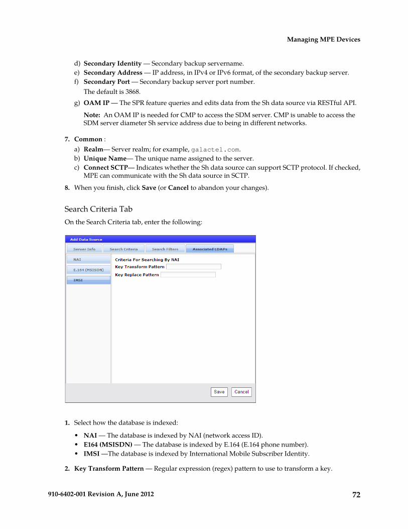
d) Secondary Identity — Secondary backup servername.e) Secondary Address — IP address, in IPv4 or IPv6 format, of the secondary backup server.f) Secondary Port — Secondary backup server port number.
The default is 3868.g) OAM IP — The SPR feature queries and edits data from the Sh data source via RESTful API.
Note: An OAM IP is needed for CMP to access the SDM server. CMP is unable to access theSDM server diameter Sh service address due to being in different networks.
7. Common :a) Realm— Server realm; for example, galactel.com.b) Unique Name— The unique name assigned to the server.c) Connect SCTP— Indicates whether the Sh data source can support SCTP protocol. If checked,
MPE can communicate with the Sh data source in SCTP.
8. When you finish, click Save (or Cancel to abandon your changes).
Search Criteria TabOn the Search Criteria tab, enter the following:
1. Select how the database is indexed:
• NAI — The database is indexed by NAI (network access ID).• E164 (MSISDN) — The database is indexed by E.164 (E.164 phone number).• IMSI —The database is indexed by International Mobile Subscriber Identity.
2. Key Transform Pattern — Regular expression (regex) pattern to use to transform a key.
72910-6402-001 Revision A, June 2012
Managing MPE Devices

3. Key Replace Pattern — Replacement string to use to transform the key.For example, 17$2 means the new string starts with “17” and is followed by the group 2 ($2)pattern.
4. When you finish, click Save (or Cancel to abandon your changes).
Search Filters TabYou can configure any number of filters per search type per data source. For example, if a data sourcesupports searching by MSISDN and IMSI, you can define multiple MSISDN and IMSI filters. Tekelecrecommends ordering filtered data sources higher than unfiltered ones.
To define filters, on the Search Filters tab, enter the following:
1. Key Type — Select from the list:
• NAI — Network address ID• E164 (MSISDN) — E.164 phone number• IMSI (the default) — International Mobile Subscriber Identity
2. Expression — Enter a regular expression. For example:
• 508.* — Matches numbers beginning with “508”• *@galactel.com — Matches strings ending with “@galactel.com”• .* — Matches any input string
To add the expression to the list, click Add. To remove an expression from the list, select it in thelist and click Delete.
3. When you finish, click Save (or Cancel to discard your changes).
73910-6402-001 Revision A, June 2012
Managing MPE Devices

The Sh data source filters are defined.
External Fields TabThe External Fields tab lets you define external fields and map them to specific LDAP attributes anddistinguished names (DNs). This lets you use the same external field name when writing a policy thatwill be deployed across multiple MPE devices. You can define up to 50 atributes per data source.
The functions available from the External Fields tab are as follows:
• To add a field to the table — Click Add; the Add External Field window opens. Enter the externalfield name, LDAP attribute name, and distinguished name (DN). Click Save when you finish (orCancel to close the window and abandon your change).
• To clone a field in the table — Select an existing field in the table and click Clone; the CloneExternal Field window opens with that field’s information filled in. Make changes as required.Click Save when you finish (or Cancel to close the window and abandon your change).
• To edit a field in the table — To edit a field name or value, select the field in the table and clickEdit; the Edit External Field window opens, displaying the field’s information. Make changes asrequired. Click Save when you finish (or Cancel to close the window and abandon your change).
• To delete a field from the table — Select the field(s) in the table and click Delete; you are prompted,“Are you sure you want to delete the selected External Field(s)?” Click Delete to remove the datasource entry (or Cancel to cancel your request).
Policy Server Groups
For organizational purposes, you can aggregate the MPE devices in your network into groups. Forexample, you can use groups to define authorization scopes. The following subsections describe howto manage policy server groups.
74910-6402-001 Revision A, June 2012
Managing MPE Devices
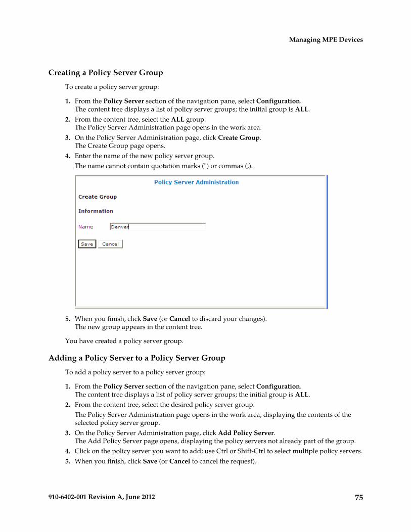
Creating a Policy Server Group
To create a policy server group:
1. From the Policy Server section of the navigation pane, select Configuration.The content tree displays a list of policy server groups; the initial group is ALL.
2. From the content tree, select the ALL group.The Policy Server Administration page opens in the work area.
3. On the Policy Server Administration page, click Create Group.The Create Group page opens.
4. Enter the name of the new policy server group.The name cannot contain quotation marks (") or commas (,).
5. When you finish, click Save (or Cancel to discard your changes).The new group appears in the content tree.
You have created a policy server group.
Adding a Policy Server to a Policy Server Group
To add a policy server to a policy server group:
1. From the Policy Server section of the navigation pane, select Configuration.The content tree displays a list of policy server groups; the initial group is ALL.
2. From the content tree, select the desired policy server group.The Policy Server Administration page opens in the work area, displaying the contents of theselected policy server group.
3. On the Policy Server Administration page, click Add Policy Server.The Add Policy Server page opens, displaying the policy servers not already part of the group.
4. Click on the policy server you want to add; use Ctrl or Shift-Ctrl to select multiple policy servers.5. When you finish, click Save (or Cancel to cancel the request).
75910-6402-001 Revision A, June 2012
Managing MPE Devices

The policy server is added to the selected group.
Creating a Policy Server Sub-group
You can create sub-groups to further organize your policy server network. To add a policy serversub-group to an existing policy server group:
1. From the Policy Server section of the navigation pane, select Configuration.The content tree displays a list of policy server groups; the initial group is ALL.
2. From the content tree, select the desired policy server group.The Policy Server Administration page opens in the work area, displaying the contents of theselected policy server group.
3. On the Policy Server Administration page, click Create Sub-Group.The Create Group page opens.
4. Enter the name of the new sub-group.The name cannot contain quotation marks (") or commas (,).
5. When you finish, click Save (or Cancel to discard your changes).The sub-group is added to the selected group.
Renaming a Policy Server Group
To modify the name assigned to a policy server group or sub-group:
1. From the Policy Server section of the navigation pane, select Configuration.The content tree displays a list of policy server groups; the initial group is ALL.
2. From the content tree, select the desired policy server group or sub-group.The Policy Server Administration page opens in the work area.
3. On the Policy Server Administration page, click Modify.The Modify Group page opens.
4. Enter the new name in the Name field.The name cannot contain quotation marks (") or commas (,).
5. When you finish, click Save (or Cancel to cancel the request).The group is renamed.
Removing a Policy Server Profile from a Policy Server Group
Removing a policy server profile from a policy server group or sub-group does not delete the profile.To delete a policy server profile, see Deleting a Policy Server Profile.
To remove a policy server profile from a policy server group or sub-group:
1. From the Policy Server section of the navigation pane, select Configuration.The content tree displays a list of policy server groups; the initial group is ALL.
2. From the content tree, select the desired policy server group or sub-group.The Policy Server Administration page opens in the work area, displaying the contents of theselected policy server group or sub-group.
76910-6402-001 Revision A, June 2012
Managing MPE Devices

3. Remove the desired policy server profile using one of the following methods:
Note: The policy server is removed immediately; there is no confirmation message.
• Click the Remove (scissors) icon located next to the policy server you want to remove.• From the content tree, select the policy server; the Policy Server Administration page opens.
Click the System tab; the System tab opens. Click Remove.
The policy server is removed from the group or sub-group.
Deleting a Policy Server Group
Deleting a policy server group also deletes any associated sub-groups. However, any policy serverprofiles associated with the deleted group or sub-groups remain in the ALL group. You cannot deletethe ALL group.
To delete a policy server group or subgroup:
1. From the Policy Server section of the navigation pane, select Configuration.The content tree displays a list of policy server groups; the initial group is ALL.
2. From the content tree, select the desired policy server group or sub-group.The Policy Server Administration page opens in the work area, displaying the contents of theselected policy server group or sub-group.
3. On the Policy Server Administration page, click Delete.You are prompted, “Are you sure you want to delete this Group?”
4. Click OK to delete the group (or Cancel to cancel the request).
The policy group is deleted.
Reapplying the Configuration to a Policy Server
The CMP lets you reapply the configuration to each MPE device. When you reapply the configuration,the CMP reconfigures the corresponding MPE device completely with topology information (such asnetwork elements and links), ensuring that the MPE device configuration matches that within theCMP. This action is not needed during normal operation but is useful in the following situations:
• When both servers of a cluster are replaced, the new servers come up initially with default values.(The Policy Management Platform Configuration User's Guide describes how to restore both single-serverand clustered configurations.) Reapplying the configuration lets you redeploy the entireconfiguration rather than reconfiguring the MPE device field by field. You should also apply theRediscover Cluster operation to the CMP to re-initialize the Cluster Information Report for thedevice, thereby clearing out the failed servers’ status.
• After upgrading the software on an MPE device, Tekelec recommends that you reapply theconfiguration from the CMP to ensure that the upgraded MPE device and the CMP are synchronized.
• There are situations in which it is possible for an MPE device configuration to go out ofsynchronization with the CMP; for example, when a break in the network causes communicationto fail between the CMP and the MPE device. If such a condition occurs, the CMP displays theMPE device status as “Configuration Mismatch.” In this case, reapplying the configuration bringsthe MPE device back into synchronization with the CMP.
77910-6402-001 Revision A, June 2012
Managing MPE Devices

To reapply the configuration associated with an MPE device:
1. From the Policy Server section of the navigation pane, select Configuration.The content tree displays a list of policy server groups; the initial group is ALL.
2. From the content tree, select the ALL group.The Policy Server Administration page opens in the work area.
3. From the group ALL, select the desired MPE device.The Policy Server Administration page displays information for that device.
4. On the Policy Server Administration page, select the System tab and click Reapply Configuration.The profile information is saved to the MPE device.
Checking the Status of an MPE Server
The CMP lets you view the status of MPE servers, either collectively (all servers within the topology)or individually.
• Group View — Select ALL from the policy server content tree to view all the defined MPE servers,or select a specific policy server group or sub-group to view just the servers associated with thatgroup. The display in the work area includes a status column that indicates the following states:
• On-line — The servers in the cluster have completed startup, and their database services aresynchronized.
• Degraded — At least one server is not functioning properly (its database services are notsynchronized or it has not completed startup) or has failed, but the cluster continues to functionwith the active server. This state sets alarm ID 70005 with severity Major.
Note: If a cluster status is Degraded, but the server details do not show any failures ordisconnections, then the cluster is performing a database synchronization operation. Until thesynchronization process has completed, the server cannot perform as the active server.
• Out of Service — Communication to the cluster has been lost.
• Policy Server Profile View — Select a server from the content tree, then click the System tab toview the device’s current operating status (On-line or Off-line) and profile configuration.
Figure 9: Group View shows an example of a Group View in which one of the servers is degraded.
78910-6402-001 Revision A, June 2012
Managing MPE Devices

Figure 9: Group View
• Trash can icon — Click on the trash can icon to delete an MPE server.
Policy Server Reports
The Reports tab lets you view a hierarchical set of reports that you can use to monitor both the statusand the activity of a specific policy server.
Each report page provides the following information:
• Mode — Shows whether data collection is currently Active or Paused, Absolute (displayingstatistics since the last reset) or Delta (displaying changes in the statistics during the last 10-secondrefresh period).
• Buttons — The buttons let you navigate between reports, or control the information displayedwithin the report. The following list describes the buttons; which buttons are available depend onyour configuration and differ from one report page to the next:
• Show Absolute/Show Deltas — Switches between absolute mode (statistics since last reset)and delta mode (statistics since last display).
• Reset All Counters — Resets all counters under Policy Statistics and Protocol Statistics back toinitial values except for “Session count” and “Downstream Bandwidth” under Network Elements.
• Rediscover Cluster — Rediscovers the cluster, deleting any failed servers that have been removedfrom service.
• Pause/Resume — Stops or restarts automatic refreshing of displayed information. The refreshperiod is 10 seconds.
• Cancel — Returns to previous page.
The CMP also displays various statistics and counters related to the following:
• Cluster Information — Information about the cluster.• Blades — Information about the individual physical components in the cluster.• Time Period — Information about the current time period and transition status.• Profile Statistics — Information about quota profiles and traffic profiles.• Session Cleanup Statistics — Information about removal of stranded subscriber sessions.
79910-6402-001 Revision A, June 2012
Managing MPE Devices

• Policy Statistics — Information about the execution of policy rules.• Protocol Statistics — Information about the active network protocols.• Latency Statistics — Information about protocol latency.• Event Trigger Statistics — Information about triggered events.• Error Statistics — Information about any errors, arranged by protocol.• Data Source Statistics — Information about LDAP, Sh, and SPR activity.• KPI Interval Statistics — Information about the configured reporting interval for key performance
indicator (KPI) statistics.
Cluster Information Report
The fields that are displayed in the Cluster Information Report section include the following:
• Cluster Status — The status of the cluster:
• On-line: If one server, it is active; if two servers, one is active and one is standby; if three servers,one is active, one is standby, one is spare.
• Degraded: One server is active, but at least one other server is not available.• Out-Of-Service: No server is active.
• Site Preference — The preference of the cluster (Normal or Reversed). Default status is Normal.
Also within the Cluster Information Report is a listing of all the servers (blades) contained within the
cluster. A symbol ( ) indicates which server currently has the external connection (the activeserver). The report also lists the following server-specific information:
• Overall — Displays the current topology state (Active, Standby, Forced-Standby, or Spare), numberof server (blade) failures, and total uptime (time providing active or standby policy or GUI service).For the definitions of these states, see Server Status.
• Utilization — Displays the percentage utilization of disk (of the /var/camiant filesystem), CPU,and memory.
The Actions buttons let you restart the Policy Management software on the server or restart the serveritself.
Time Period
The Time Period section shows the current time period for the cluster (“none” if the cluster is not inany time period) and the status of its last transition:
• N/A — No time periods are defined, or the cluster has not yet transitioned to any time periods.• Transitioning — The cluster is updating sessions based on a time period’s transition.• Completed — The cluster has updated all affected sessions (either successfully or not) after a time
period transition.• Aborted — The transition was stopped by a CMP user.• Incomplete — The transition has not completed, due to a communication failure with an enforcement
device.
80910-6402-001 Revision A, June 2012
Managing MPE Devices

Policy Statistics
The Policy Statistics section summarizes policy rule activity within the MPE device. This is presentedas a table of statistics for each policy rule that is configured for the MPE device.
The following statistics are included:
• Name — Name of the policy being polled.• Evaluated — Number of times the conditions in the policy were evaluated.• Executed — Number of times policy actions were executed. This implies that the conditions in the
policy evaluated to be true.• Ignored — Number of times the policy was ignored. This can happen because the policy conditions
refer to data which was not applicable given the context in which it was evaluated.
To see statistics per policy, click the (details...) hyperlink. All existing policies are displayed in a statisticstable, with Evaluated, Executed, and Ignored counter values listed for each.
To see details for a specific policy with the distribution of execution time, click on the Policy Name.In addition to Evaluated, Executed, and Ignored, the following details are displayed:
• Total Execution Time (ms) — The summary of all execution durations, where execution durationis measured starting at the beginning of the policy conditions evaluation until the execution finishing.
• Maximum Execution time (ms) — The longest execution duration of the policy.• Average Execution time (ms) — The average of all execution durations of the policy.• Processing Time Statistics - number of policies processed per time range, in ms. Ranges include
0-20, 20-40, 40-60, 60-80, 80-100, 100-150, 150-200, 200-250, and >250.
Protocol Statistics
The Protocol Statistics section summarizes the protocol activity within the MPE device. This informationis presented as a table of summary statistics for each protocol. Some protocols are broken down intosub-entries to distinguish between the different types of protocol activity.
The summary protocol statistics are the following:
• Connections — If the protocol is connection oriented, the current number of established connectionsusing each protocol.
• Total client messages in / out — The total number of incoming and outgoing messages receivedand sent using each protocol.
Figure 10: Sample Protocol Statistics shows a sample.
Figure 10: Sample Protocol Statistics
81910-6402-001 Revision A, June 2012
Managing MPE Devices

You can click the name of each entry in the Protocol Statistics table to display a detailed report page.For most protocols, this report page displays a set of counters that break down the protocol activityby message type, message response type, errors, and so on.
Many of the protocol report pages also include a table that summarizes the activity for each client orserver with which the MPE device is communicating through that protocol. These tables let you selecta specific entry to further examine detailed protocol statistics that are specific to that client or server.
Since many of these statistics contain detailed protocol-specific summaries of information, the specificdefinitions of the information that is displayed are not included here. For more specific information,see the appropriate technical specification that describes the protocol in which you are interested (seeRelated Publications).
Note: 1. Statistical information is returned from the MPE device as a series of running “peg counts.”To arrive at interval rate information, such as session success and failure counts, two intervals areneeded to perform the difference calculation. Also, statistical information, such as session activationcounts, is kept in memory and is therefore not persisted across the cluster. After a failover,non-persistent metrics must be repopulated based on resampling from the newly active primary server.Therefore, when an MPE device is brought on line, or after a failover, one or more sample periods willdisplay no statistical information.
2. Historical network element statistical data is inaccurate if configuration values (such as capacity)were changed in the interim. If the network element was renamed in the interim, no historical data isreturned.
The DRMA statistics are the following:
• RUR_SEND_COUNT — The number of RUR messages sent.• RUR_RECV_COUNT— The number of RUR messages received.• RUA_SEND_SUCCESS_COUNT— The number of RUA success messages sent.• RUA_RECV_SUCCESS_COUNT— The number of RUA success messages received.• RUA_SEND_FAILURE_COUNT— The number of RUA failure messages sent.• RUA_RECV_FAILURE_COUNT— The number of RUA failure messages received.• LNR_SEND_COUNT— The number of LNR messages sent.• LNR_RECV_COUNT— The number of LNR messages received.• LNA_SEND_SUCCESS_COUNT— The number of LNA success messages sent.• LNA_RECV_SUCCESS_COUNT— The number of LNA success messages received.• LNA_SEND_FAILURE_COUNT— The number of LNA failure messages sent.• LNA_RECV_FAILURE_COUNT— The number of LNA failure messages received.• LSR_SEND_COUNT— The number of LSR messages sent.• LSR_RECV_COUNT— The number of LSR messages received.• LSA_SEND_SUCCESS_COUNT— The number of LSA success messages sent.• LSA_RECV_SUCCESS_COUNT— The number of LSA success messages received.• LSA_SEND_FAILURE_COUNT— The number of LSA failure messages sent.• LSA_RECV_FAILURE_COUNT— The number of LSA failure messages received.
Error Statistics
The Error Statistics section summarizes any protocol-related errors reported by the MPE device. Thisis presented as a table of overall statistics for each protocol that is configured for the MPE device.Figure 11: Sample Error Statistics shows a sample.
82910-6402-001 Revision A, June 2012
Managing MPE Devices

Figure 11: Sample Error Statistics
The following summary statistics are displayed:
• Error — List of protocols configured on this MPE device.• Total errors received/sent — Total number of errors received or sent in this protocol.
You can click the name of each entry in the Error Statistics table to display a detailed report page. Formost protocols, this report page displays a set of counters that break down the errors by error codeand the remote identity of each client or server with which the MPE device is communicating throughthat protocol.
Data Source Statistics
The Data Source Statistics section summarizes the data source activity within the MPE device.Information is available for each data source. You can click the name of each entry in the Data SourceStatistics table to display a detailed report page.
Sh StatisticsFor an Sh data source, the Data Source Statistics page displays the following statistics:
• Number of successful searches• Number of unsuccessful searches• Number of searches that failed because of errors• Max Time spent on successful search (ms)• Max Time spent on unsuccessful search (ms)• Average time spent on successful searches (ms)• Average time spent on unsuccessful searches (ms)
SPR StatisticsFor an SPR system, Figure 12: SPR Data Source Statistics shows an example of the statistics collected.
83910-6402-001 Revision A, June 2012
Managing MPE Devices

Figure 12: SPR Data Source Statistics
Database Statistics
The Database Statistics section summarizes the read/write activity for the MPE device database. ClickDatabase Status Statistics to display the last reset time (that is, the last time that you clicked ResetAll Counters), the last collection time, and cumulative read/write activity. Data is collected every 10seconds.
Interval Statistics
The Interval Statistics section summarizes the maximum key performance indicator (KPI) valuesrecorded by the Policy Management cluster during the previous recording interval. Intervals arerecorded on the quarter hour.
The following interval statistics are displayed:
• Interval StartTime — Timestamp of when the current interval started.
84910-6402-001 Revision A, June 2012
Managing MPE Devices

• Configured Length (Seconds) — Configured interval length. The value of 900 seconds (15 minutes)is fixed.
• Actual Length (Seconds) — Actual interval length. When data is collected over a full interval, thisvalue matches the Configured Length value.
• Is Complete — Displays 0 or 1, where 1 indicates that data was collected for a full interval.• Interval MaxTransactionsPerSecond — The highest value of the counter MaxTransactionsPerSecond
during the previous interval.• Interval MaxMRABindingCount — The highest value of the counter MaxMRABindingCount
during the previous interval. (This value is 0 on MPE clusters.)• Interval MaxSessionCount — The highest value of the counter MaxSessionCount during the
previous interval.• Interval MaxPDNConnectionCount — The highest value of the counter MaxPDNConnectionCount
during the previous interval.
Note: If a cluster has just started up and no data is available, the Interval StartTime is displayed as"Undefined" and the maximum values are displayed as 0. If a cluster has started up and a recordinginterval has completed but it is less than 15 minutes, the value of Actual Length will not matchConfigured Length, and the maximum values are displayed as 0.
Policy Server Logs
The log files trace the activity of a Policy Management device. You can view and configure the logsfor an individual cluster.
To view the log:
1. From the Policy Server section of the navigation pane, select Configuration.The content tree displays a list of policy server groups.
2. From the content tree, select the desired Policy Management device.The Policy Server Administration page opens in the work area.
3. On the Policy Server Administration page, select the Logs tab.Log information, including the log levels, is displayed. Figure 13: Policy Server Logs Tab shows anexample. You can configure the following logs:
• Trace log — records application-level notifications• Policy Syslog — supports the standard UNIX logging system, in conformance with RFC 3164• SMS log — contains all Short Message Peer-to-Peer Protocol (SMPP) notification sent by the
MPE device as well as delivery receipts from a Short Message Service Center (SMSC) server.• SMTP log — contains all Simple Mail Transfer Protocol (SMTP) messages sent by the MPE
device.
85910-6402-001 Revision A, June 2012
Managing MPE Devices

Figure 13: Policy Server Logs Tab
The Trace Log
The trace log records Policy Management application notifications, such as protocol messages, policymessages, and custom messages generated by policy actions, for individual servers. Trace logs are notreplicated between servers in a cluster, but they persist after failovers. You can use the log to debugproblems by tracing through application-level messages. You can configure the severity of messagesthat are recorded in the trace log. For more information, see Configuring Log Settings.
Note: Prior to V7.5, the trace log was called the event log, which also contained platform events.Platform and connectivity events are now displayed as alarms. Additionally, prior to V7.5, a policylog file recorded the activity of the Policy Rules Engine, at seven levels: Alert, Critical, Error, Warning,Notice, Info, and Debug. This information is now recorded in the trace log, which is a database table,at eight levels: Emergency (ID 4560), Alert (ID 4561), Critical (4562), Error (ID 4563), Warning (ID4564), Notice (ID 4565) Info (ID 4566), and Debug (4567).
To view log information using the Trace Log Viewer:
1. Select the device to view:
• To view an MPE device, from the Policy Server section of the navigation pane, selectConfiguration.
• To view an MRA device, from the MRA section of the navigation pane, select Configuration.
The content tree displays a list of groups; the initial group is ALL.2. From the content tree, select the device.
86910-6402-001 Revision A, June 2012
Managing MPE Devices

The appropriate Administration page opens in the work area.3. On the Administration page, select the Logs tab.
Log information for the selected device is displayed.4. Click View Trace Log.
The Trace Log Viewer window opens. While data is being retrieved, the in-progress message“Scanning Trace Logs” appears.All events contain the following information:
• Date/Time — Event timestamp. This time is relative to the server time.• Code — The event code. For information about event codes and messages, see the Policy
Management Troubleshooting Guide.• Severity — Severity level of the event. Application-level trace log entries are not logged at a
higher level than Error.• Message — The message associated with the event. If additional information is available, the
event entry shows as a link. Click on the link to see additional detail in the frame below.
5. You can filter the events displayed using the following:
• Trace Log Viewer for Server — Select the active, standby, or spare server• Start Date/Time — Click the calendar icon, select the desired starting date and time, then click
Enter.• End Date/Time — Click the calendar icon, select the desired ending date and time, then click
Enter.• Trace Code(s) — Enter one or a comma-separated list of trace code IDs. Trace code IDs are
integer strings up to 10 digits long.• Use timezone of remote server for Start Date/Time — Select to use the time of a remote server
(if it is in a different time zone) instead of the time of the CMP server.• Severity — Filter by severity level. Events with the selected severity and higher are displayed.
For example, if the severity selected is Warning, the trace log displays events with the severitylevel Warning.
• Contains — Enter a text string to search for. For example, if you enter “connection,” all eventscontaining the word “connection” appear.
Note: The Start Date/Time setting overrides the Contains setting. For example, if you searchfor events happening this month, and search for a string that appeared in events last monthand this month, only results from this month appear.
After entering the filtering information, click Search. The selected events are displayed.
By default, the window displays 25 events per page. You can change this to 50, 75, or 100 events perpage by selecting a value from the Display results per page pulldown list.
Events that occur after the Trace Log Viewer starts are not visible until you refresh the display. Torefresh the display, click one of the following buttons:
• Show Most Recent — Applies filter settings and refreshes the display. This displays the mostrecent log entries that fit the filtering criteria.
• Next/Prev — Once the number of trace log entries exceeds the page limit, pagination is applied.Use the Prev or Next buttons to navigate through the trace log entries. When the Next button isnot visible, you have reached the most recent log entries; when the Prev button is not visible, youhave reached the oldest log entries.
87910-6402-001 Revision A, June 2012
Managing MPE Devices

• First/Last — Once the number of trace log entries exceeds the page limit, pagination is applied.Use the First and Last buttons to navigate to the beginning or end of the trace log. When the Lastbutton is not visible, you have reached the end; when the First button is not visible, you havereached the beginning.
When you are finished viewing the trace log, click Close.
Syslog Support
Notifications generated by policy actions are sent to the standard UNIX syslog. No other notificationsare forwarded to syslog. For information on policy actions, see Optional Actions.
Note: This feature is separate from TPD syslog support.
You can define multiple destinations for notifications, and filter notifications by severity level. Formore information, see Configuring Log Settings.
The SMPP Log
The SMPP log, /var/Camiant/log/SMPP.log, contains all Short Message Peer-to-Peer Protocolnotifications sent by the MPE device as well as delivery receipts from a Short Message Service Center(SMSC) server. SMPP info appears on the MPE Logs tab of the MPE Configuration page, under theSMS Log Configuration heading. You can configure the severity of messages that are written to theSMPP log as well as set a forwarding address. For more information, see Configuring Log Settings.
The SMTP Log
The SMTP log, /var/Camiant/log/SMTP.log, contains all Simple Mail Transfer Protocol messagessent by the MPE device, as well as any ACK messages received from a mail transfer agent (MTA).SMTP Log info appears on the MPE Logs tab of the MPE Configuration page. You can configure theseverity of messages that are written to the SMTP log. For more information, see Configuring LogSettings.
Configuring Log Settings
From the Logs tab you can configure the log settings for the servers in a cluster. To configure logsettings:
1. From the Logs tab, click Modify.The Modify Settings fields open in the work area.
2. In the Modify Trace Log Settings section of the page, configure the Trace Log Level.This setting indicates the minimum severity of messages that are recorded in the trace log. Theseseverity levels correspond to the syslog message severities from RFC 3164. Adjusting this settingallows new notifications, at or above the configured severity, to be recorded in the trace log. Thelevels are:
• Emergency — Provides the least amount of logging, recording only notification of events causingthe system to be unusable.
• Alert — Action must be taken immediately in order to prevent an unusable system.• Critical — Events causing service impact to operations.• Error — Designates error events which may or may not be fatal to the application.• Warning (the default) — Designates potentially harmful situations.
88910-6402-001 Revision A, June 2012
Managing MPE Devices

• Notice — Provides messages that may be of significant interest that occur during normaloperation.
• Info — Designates informational messages highlighting overall progress of the application.• Debug — Designates information events of lower importance.• All — Used to turn on all logging.• Off — Used to turn off logging.
CAUTION: Before changing the default logging level, consider the implications.Lowering the trace log level setting from its default value (for example, from “Warning”to “Info”) causes more notifications to be recorded in the trace log and can adverselyaffect performance. On the other hand, raising the log level setting (for example, from“Warning” to “Alert”) causes fewer notifications to be recorded in the trace log, andcould cause you to miss important notifications.
3. In the Modify Policy Syslog Forwarding Settings section of the page, configure the syslogforwarding settings. You can direct notifications to up to five remote systems. For each system,enter the following:a) Hostname/IP Addresses — Remote system hostname or IP address.
CAUTION: Forwarding addresses are not checked for loops. If you forward eventson System A to System B, and then forward events on System B back to System A,a message flood can result, causing dropped packets.
b) Facility — Select from Local0 (the default) to Local7.c) Severity — Filters the severity of notifications that are written to syslog:
• Emergency— Provides the least amount of logging, recording only notification of events causingthe system to be unusable.
• Alert — Action must be taken immediately in order to prevent an unusable system.• Critical — Events causing service impact to operations.• Error — Designates error events which may or may not be fatal to the application.• Warning (the default) — Designates potentially harmful situations.• Notice — Provides messages that may be of significant interest that occur during normal
operation.• Info — Designates informational messages highlighting overall progress of the application.• Debug — Designates information events of lower importance.• All — Used to turn on all logging.• Off — Used to turn off logging.
4. In the Modify SMS Log Settings section of the page, configure the following:a) SMPP Log Level — Indicates the severity of messages that are written to the file SMPP.log.
Adjusting this setting allows any new events, at or above the configured severity, to be writtento the SMPP log.
Note: You can optionally enable the syslog forwarding address for new logs.
Valid levels are:
• OFF — Turns off logging.• ERROR — Designates error events which may or may not be fatal.
89910-6402-001 Revision A, June 2012
Managing MPE Devices

• WARN (the default) — Designates potentially harmful situations.• INFO — Designates informational messages highlighting overall progress.• DEBUG — Designates information events of lower importance.• TRACE — Designates informational events of very low importance.• ALL — Records all logging levels.
b) SMPP Log Forwarding IP Addresses — You can forward SMPP.log entries to multiple syslogservers.
5. In the Modify SMTP Log Settings section of the page, configure the SMTP Log Level.This setting indicates the minimum severity of messages that are recorded in the SMTP log. Theseseverity levels correspond to the syslog message severities from RFC 3164. Adjusting this settingallows new notifications, at or above the configured severity, to be recorded in the SMTP log. Thelevels are:
• OFF — Turns off logging.• ERROR — Designates error events which may or may not be fatal.• WARN (the default) — Designates potentially harmful situations.• INFO — Designates informational messages highlighting overall progress.• DEBUG — Designates information events of lower importance.• TRACE — Designates informational events of very low importance.• ALL — Records all logging levels.
6. When you finish, click OK (or Cancel to discard your changes).The log configurations are changed.
90910-6402-001 Revision A, June 2012
Managing MPE Devices

Chapter
5Configuring Protocol Routing
Routing enables a Policy Management device toforward requests to other Policy Management
Topics:
• Configuring Diameter Peers.....92 devices for further processing. The following routingmessages and protocols are supported:• Configuring Diameter Routes.....93
• Diameter Rx messages• Diameter applications: Rx, Gq, Ty, Gxx, Gx, and
Gy
91910-6402-001 Revision A, June 2012

Configuring Diameter Peers
Policy Management devices support Diameter Rx, Gq, Ty, Gxx, Gx, and Gy applications. For example,traffic control is supported using the Diameter Gx application. When a subscriber attaches to thenetwork (for example, using a phone) via a GGSN (Gateway GPRS Support Node), the GSSN canestablish a session with an MPE device using a Diameter Gx CCR (Credit Control Request) message.The MPE device responds to the request with a Gx CCA (Credit Control Answer) message.
To configure Diameter peers:
1. From the Policy Server section of the navigation pane, select Configuration.The content tree displays a list of policy server groups.
2. From the content tree, select the desired MPE device.The Policy Server Administration page opens in the work area.
3. On the Policy Server Administration page, select the Diameter Routing tab.The Diameter Routing configuration settings are displayed.
4. Click Modify Peers. The Modify the Diameter Peer Table page opens. The functions available fromthis table are as follows:
• To add a peer to the table — Click Add; the Add Diameter Peer window opens:
Enter the following:
• Configured MRAs/MPEs (optional) — If you are defining an existing Policy Managementcluster as a Diameter peer, select it from this list; the other fields are populated.
• Name — Name of the peer device (which must be unique within the CMP database).• IP Address — IP address in IPv4 or IPv6 format of the peer device.
If not specified, the MPE device uses a DNS lookup to resolve the value in the DiameterIdentity field into an IP address and try to connect.
• Diameter Realm — The peer's domain of responsibility (for example, galactel.com).
92910-6402-001 Revision A, June 2012
Configuring Protocol Routing

• Diameter Identity — Fully qualified domain name (FQDN) of the peer device (for example,mpe33.galactel.com).
• Connect SCTP— Connects the SCTP to the Diameter Peer. If selected, the field is set to true.If not selected, the field is set to false.
• IP Port— The port number of the primary server.• Watchdog Interval— Used as a keep alive functionality. The default interval is 30 seconds.• Reconnect Delay— Used as a delay between connection retries. The default interval is 3
seconds.• Response Timeout— The maximum amount of time to wait for a response from the TDF
before declaring that the message timed out.
When you finish, click Save (or Cancel to discard your changes).• To clone a peer in the table — Select an existing peer in the table and click Clone; the Clone
Diameter Peer window opens with that peer device’s information filled in. Make changes asrequired. When you finish, click Save (or Cancel to discard your changes).
• To edit a peer in the table — Select an existing peer in the table and click Edit; the Edit DiameterPeer window opens with that peer device’s information. Make changes as required. When youfinish, click Save (or Cancel to discard your changes).
• To delete a peer from the table — Select an existing peer in the table and click Delete; you areprompted, “Are you sure you want to delete the selected Diameter Peer(s)?” Click Delete (orCancel to cancel your request). The peer entry is removed.
5. When you finish, click Save (or Cancel to discard your changes).The Diameter peer is added to the table.
You have defined a Diameter peer.
Configuring Diameter Routes
By default, Diameter messages are processed locally. In a network with multiple Policy Managementdevices, messages can be routed, by realm, application, or user ID, for processing by peers or otherrealms.
To configure the Diameter route table:
1. From the Policy Server section of the navigation pane, select Configuration.The content tree displays a list of policy server groups.
2. From the content tree, select the desired policy server.The Policy Server Administration page opens in the work area.
3. On the Policy Server Administration page, select the Diameter Routing tab.The Diameter Routing configuration settings are displayed.
4. Click Modify Routes.The Modify the Diameter Route Table page opens.
The functions available from this table are as follows:
• To add a route to the table — Click Add; the Add Diameter Route window opens:
93910-6402-001 Revision A, June 2012
Configuring Protocol Routing

The fields are as follows:
• Diameter Realm — For example, galactel.com.• Application ID — Select Rx (the default), Gq, Ty, Gx, Gy, Gxx, or All.
Note: You can include only one application per route rule. For multiple applications, createmultiple rules.
• User ID type — Select ANY (the default), E.164(MSISDN), IMSI, IP, NAI, PRIVATE,SIP_URI, or USERNAME.
• Value — Enter the user ID to be routed (for example, an NAI or E.164 number). Separateuser IDs using a comma (,); use an asterisk (*) as a wildcard character. To add the user ID tothe list, click Add; to remove one or more user IDs from the list, select them and click Delete.
• Evaluate as Regular Expression — The check box allows the matching of route criteria usingregular expression syntax, opposed to the previously supported matching wildcards.
• Action — Select PROXY (stateful route, the default), RELAY (stateless route), or LOCAL(process on this device).
• Server ID — Select a destination peer from the list.
Note: If desired, you can define a server with a Diameter identity.
When you finish, click Save (or Cancel to abandon your changes).• To change the order of a route in the table — Select an existing route in the table and click Up
or Down. The order of routes is changed.• To clone a route in the table — Select an existing route in the table and click Clone; the Clone
Diameter Route window opens with that route’s information filled in. Make changes as required.When you finish, click Save (or Cancel to discard your changes).
• To edit a route in the table — Select an existing route in the table and click Edit; the EditDiameter Route window opens with that route’s information. Make changes as required. Whenyou finish, click Save (or Cancel to discard your changes).
• To delete a route from the table — Select one or more existing routes and click Delete; you areprompted, “Are you sure you want to delete the selected Diameter Route(s)?” Click Delete (orCancel to cancel your request). The route entry is removed.
94910-6402-001 Revision A, June 2012
Configuring Protocol Routing

5. To define the default route, click Edit in the Default Route section.The Edit Default Route window opens:
Enter the default action (PROXY, RELAY, or LOCAL) and peer server ID. When you finish, clickSave (or Cancel to discard your changes).
6. To delete the default route, click Delete.7. When you finish, click Save (or Cancel to discard your changes).
The Diameter routes are configured.
95910-6402-001 Revision A, June 2012
Configuring Protocol Routing

Chapter
6Managing Network Elements
Managing Network Elements describes how to definenetwork elements within the CMP.
Topics:
• About Network Elements.....97• Defining a Network Element.....97• Configuring Options for Network Elements....100• Associating a Network Element with an MPE
Device.....104• Working with Network Element Groups.....105
96910-6402-001 Revision A, June 2012

About Network Elements
A network element is a high-level device, server, or other entity within your network for which youwould like to use an MPE device to manage Quality of Service (QoS). Examples include apacket-switched data network (PSDN), a gateway GPRS support node (GGSN), a router, a server, ora zone. Once you have defined a network element in the CMP, you associate it with the MPE devicethat you will use to manage that element.
There are also lower-level entities within the network that the MPE device manages that are notconsidered network elements. These are sub-elements, such as an interface on a router, or devices thatare connected directly to network elements. Typically, there is no need to define these lower-levelentities, because once a network element is associated with an MPE device the lower-level devicesrelated to that network element are discovered and associated automatically.
Create a network element profile for each device you are associating with an MPE device. After defininga network element in the CMP, configure its protocol options. The options available depend on thenetwork element type.
For ease of management, once you define network elements, you can combine them into networkelement groups.
Defining a Network Element
You must define a network element for each device associated with any of the MPE devices withinthe network. To define a network element:
1. From the Network section of the navigation pane, select Network Elements.The content tree displays a list of network element groups; the initial group is ALL.
2. From the content tree, select the network element group in which you want to define the networkelement.(See Creating a Network Element Group for information on creating network element groups.)The Network Element Administration page opens in the work area.
3. On the Network Element Administration page, click Create Network Element.The New Network Element page opens.
4. Enter information as appropriate for the network element:a) Name (required) — The name you assign to the network element.
Enter up to 255 alphanumeric characters. The name can include underscores (_), hyphens (-),colons (:), and periods (.).
b) Host Name/IP Address (required) — Registered domain name, or IP address in IPv4 or IPv6format, assigned to the network element.
c) Backup Host Name — Alternate address that is used if communication between the MPE deviceand the network element’s primary address fails.
d) Description/Location — Free-form text.Enter up to 250 characters.
e) Type (required) — Select the type of network element.
97910-6402-001 Revision A, June 2012
Managing Network Elements

The supported types are:
• GGSN — Gateway GPRS Support Node• HSGW — HRPD Serving Gateway• PGW — Packet Data Network Gateway• SGW — Serving Gateway• DPI — Deep Packet Inspection device
f) Capability — with the following options:
• TDF-Solicit — DPI accepts Sd session establishment requests from the MPE device.• Time-Tariff — DPI supports Time-Tariff functionality.• Usage-Report — DPI is compatible with usage_report event trigger value 26.
g) Capacity — The bandwidth allocated to this network element.
5. Select one or more policy servers (MPE devices) to associate with this network element.6. Select one or moreMRA devices to associate with this network element.7. To add a network element to a network element group, select the desired group (see Adding a
Network Element to a Network Element Group).8. When you finish, click Save (or Cancel to discard your changes).
The network element is displayed in the Network Element Administration page.
You have created the definition for a network element.
Modifying a Network Element
To modify a network element:
1. From the Network section of the navigation pane, select Network Elements.The content tree displays a list of network element groups; the initial group is ALL.
2. From the content tree, select the desired network element.The Network Element Administration page opens in the work area.
3. On the Network Element Administration page, click Modify.The Modify Network Element page opens.
4. Modify network element information as required.For a description of the fields contained on this page, see Defining a Network Element.
5. When you finish, click Save (or Cancel to discard your changes).
The network element definition is modified.
Deleting Network Elements
Deleting a network element definition removes it from the list of items that a Policy Managementdevice can support. To delete a network element definition, delete it from the ALL group. Deleting anetwork element from the ALL group also deletes it from every group with which it is associated.
To delete a network element:
1. From the Network section of the navigation pane, select Network Elements.The content tree displays a list of network element groups; the initial group is ALL.
2. From the content tree, select the ALL group.
98910-6402-001 Revision A, June 2012
Managing Network Elements

The Network Element Administration page opens in the work area, displaying all defined policyservers.
3. From the work area, click the Delete icon, located to the right of the network element you want todelete:
You are prompted: “Are you sure you want to delete this Network Element?” Click OK to deletethe network element (or Cancel to cancel the request).
The network element is deleted.
Bulk Delete
A large network can contain a great many network elements. To perform a bulk delete of networkelement definitions:
1. From the Network section of the navigation pane, select Network Elements.The content tree displays a list of network element groups; the initial group is ALL.
2. From the content tree, select ALL.The Network Element Administration page opens in the work area.
3. On the Network Element Administration page, click Bulk Delete.The Bulk Delete Network Elements page opens.
4. Select the network elements or network element groups to delete.By default, the Search Pattern entry box contains an asterisk (*) to match all network elements. Tosearch for a subset of network elements, enter a search pattern (for example, star*, *pGw, or *-*)and click Filter.
5. Click Bulk Delete (or Cancel to cancel the request).The selected network element(s) or group(s) are deleted from the CMP and all associated MPEdevices.
Finding a Network Element
The Search function lets you find a specific network element within a large configuration. To searchthe CMP for a specific network element:
99910-6402-001 Revision A, June 2012
Managing Network Elements

1. From the Network section of the navigation pane, select Network Elements.The content tree displays a list of network element groups; the initial group is ALL.
2. From the content tree, select ALL.The Network Element Administration page opens in the work area.
3. On the Network Element Administration page, click Search.The Network Element Search Criteria window opens.
4. Enter the desired search criteria:
• Name — The name assigned to the network element.• Host Name/IP Address — The domain name or IP address in IPv4 or IPv6 format of the network
element.• Description — The information pertaining to the network element that helps identify it within
the network. Enter up to 250 characters.
Note: Searches are not case sensitive. Criteria can be entered using the wildcard characters '*'and '?'.
5. After entering search criteria, click Search (or Cancel to cancel the request).
The Search Results page opens in the work area, displaying the results of the search. The last searchresults are held in a Search Results folder in the content tree until you close the Search Results page.
Configuring Options for Network Elements
The following subsections describe how to configure options for a given network element type. Thenetwork elements types available depend on the operating mode in which your CMP system isconfigured, and may differ from the list given here.
Note: Configuration changes made in the CMP could potentially be reverted on an MPE device if thescheduled run time of the OSSI Distributor task on the Management Agent is before the scheduledrule time for the CMP. The discrepancy is resolved when the OSSI Distributor Task runs on the CMP.See Managing Scheduled Tasks for more information.
PDSN
To configure options for a packet-switched data network (PDSN) network element:
1. From the Network section of the navigation pane, select Network Elements.The content tree displays a list of network element groups; the initial group is ALL.
2. From the content tree, select a network element.The Network Element Administration page opens in the work area.
3. On the Network Element Administration page, select the PDSN tab and then click Modify.The Modify Network Element page opens.
4. Configure the following:a) Diameter Features
• Diameter Realm — Specifies the network element's domain of responsibility (for example,galactel.com).
100910-6402-001 Revision A, June 2012
Managing Network Elements

• Diameter Identity — Specifies the fully qualified domain name (FQDN) of the networkelement (for example, ne.galactel.com). Click Add to add the identity to the list; selectan identity from the list and click Delete to remove it.
5. When you finish, click Save (or Cancel to discard your changes).
The PDSN device is defined.
Home Agent
To configure options for a Home Agent network element:
1. From the Network section of the navigation pane, select Network Elements.The content tree displays a list of network element groups; the initial group is ALL.
2. From the content tree, select a network element.The Network Element Administration page opens in the work area.
3. On the Network Element Administration page, select the Home Agent tab and then click Modify.The Modify Network Element page opens.
4. Configure the following:a) Diameter Features
• Diameter Realm — Specifies the network element's domain of responsibility (for example,galactel.com).
• Diameter Identity — Specifies the fully qualified domain name (FQDN) of the networkelement (for example, ne.galactel.com). Click Add to add the identity to the list; selectan identity from the list and click Delete to remove it.
5. When you finish, click Save (or Cancel to discard your changes).
The Home Agent device is defined.
GGSN
To configure interface information for a GGSN network element:
1. From the Network section of the navigation pane, select Network Elements.The content tree displays a list of network element groups; the initial group is ALL.
2. From the content tree, select a network element.The Network Element Administration page opens in the work area.
3. On the Network Element Administration page, select the GGSN tab and then click Modify.The Modify Network Element page opens.
4. Configure the following information:a) Diameter Realm — Specifies the network element's domain of responsibility (for example,
galactel.com).b) Diameter Identity — Specifies the FQDN of the network element (for example,
ggsn1024.galactel.com).Click Add to define multiple identities used by the network element. To delete one of theidentities, select it from the list and click Delete.
5. When you finish, click Save (or Cancel to discard your changes).
101910-6402-001 Revision A, June 2012
Managing Network Elements

The GGSN device is defined.
HSGW
To configure interface information for an HSGW network element:
1. From the Network section of the navigation pane, select Network Elements.The content tree displays a list of network element groups; the initial group is ALL.
2. From the content tree, select a network element.The Network Element Administration page opens in the work area.
3. On the Network Element Administration page, select the HSGW tab and then click Modify.The Modify Network Element page opens.
4. Configure the following information:a) Diameter Realm — Specifies the network element's domain of responsibility (for example,
galactel.com).b) Diameter Identity — Specifies the FQDN of the network element (for example,
hsgw1024.galactel.com).Click Add to define multiple identities used by the network element. To delete one of theidentities, select it from the list and click Delete.
5. When you finish, click Save (or Cancel to discard your changes).
The HSGW device is defined.
PGW
To configure interface information for a packet data network gateway (PGW) network element:
1. From the Network section of the navigation pane, select Network Elements.The content tree displays a list of network element groups; the initial group is ALL.
2. From the content tree, select a network element.The Network Element Administration page opens in the work area.
3. On the Network Element Administration page, select the PGW tab and then click Modify.The Modify Network Element page opens.
4. Configure the following information:a) Diameter Realm — Specifies the network element's domain of responsibility (for example,
galactel.com).b) Diameter Identity — Specifies the FQDN of the network element (for example,
pgw1024.galactel.com).Click Add to define multiple identities used by the network element. To delete one of theidentities, select it from the list and click Delete.
5. When you finish, click Save (or Cancel to discard your changes).
The PGW device is defined.
SGW
To configure interface information for a signaling gateway (SGW) network element:
1. From the Network section of the navigation pane, select Network Elements.
102910-6402-001 Revision A, June 2012
Managing Network Elements

The content tree displays a list of network element groups; the initial group is ALL.2. From the content tree, select a network element.
The Network Element Administration page opens in the work area.3. On the Network Element Administration page, select the SGW tab and then click Modify.
The Modify Network Element page opens.4. Configure the following information:
a) Diameter Realm — Specifies the network element's domain of responsibility (for example,galactel.com).
b) Diameter Identity — Specifies the FQDN of the network element (for example,sgw1024.galactel.com).Click Add to define multiple identities used by the network element. To delete one of theidentities, select it from the list and click Delete.
5. When you finish, click Save (or Cancel to discard your changes).
The SGW device is defined.
DPI
To configure interface information for a deep packet inspection (DPI) network element:
1. From the Network section of the navigation pane, select Network Elements.The content tree displays a list of network element groups; the initial group is ALL.
2. From the content tree, select a network element.The Network Element Administration page opens in the work area.
3. On the Network Element Administration page, select the DPI tab and then click Modify.The Modify Network Element page opens.
4. Configure the following information:a) Diameter Realm — Specifies the network element's domain of responsibility (for example,
galactel.com).b) Diameter Identity — Specifies the FQDN of this network element (for example,
dpi56.galactel.com).Click Add to define multiple identities if used by this network element. To delete one of theidentities, select it from the list and click Delete.
c) SCTP Enabled— By selecting the check box, you can connect to the TDF using SCTP. TCP isthe default connection.
d) Allow direct connection from MPE— By selecting the check box, TDF connects directly to Sdwith the PCRF (passing on MRA.)
The following is shown only on debug mode if the option is checked:e) TDF Port— TDF listens for the Sd connection on this port.f) Reconnect Delay— Used as a delay between connection retries. The default interval is 3 seconds.g) Watch Dog Interval— Used as a keep alive functionality. The default interval is 30 seconds.h) Response Timeout— The maximum amount of time to wait for a response from the TDF before
declaring that the message timed out.i) Associated MRA Identity— The MRA that the TDF is connected. Used by the PCRF to determine
which MRA to send messages for the TDF.
103910-6402-001 Revision A, June 2012
Managing Network Elements

j) Backup TDF Identity— The backup TDF associated with this TDF. If the primary TDF connectionis down, the PCRF will send messages to the backup TDF.
5. When you finish, click Save (or Cancel to discard your changes).
The DPI device is defined.
NAS
To configure interface information for a NAS network element:
1. From the Network section of the navigation pane, select Network Elements.The content tree displays a list of network element groups; the initial group is ALL.
2. From the content tree, select a network element.The Network Element Administration page opens in the work area.
3. On the Network Element Administration page, select the NAS tab and then click Modify.The Modify Network Element page opens.
4. Configure the following information:a) Passphrase — Specifies the passphrase (RADIUS shared secret) for this network element.
Enter 1–255 characters. If the source IP address of a received message matches one of the IPaddresses configured for the NAS device, then the MPE device will attempt to decode themessage using this default passphrase. If not specified, the default passphrase configured onthe MPE device (see Managing MPE Devices) is used.
b) IP Address — Specifies up to 20 IPv4 addresses supported by this device.To add an address to the list, enter it and click Add. To delete an address, select it from the listand click Delete.
5. When you finish, click Save (or Cancel to discard your changes).
The NAS device is defined.
Associating a Network Element with an MPE Device
To associate a network element with an MPE device:
1. From the Policy Server section of the navigation pane, select Configuration.The content tree displays a list of policy server groups; the initial group is ALL.
2. From the content tree, select the desired MPE device.The Policy Server Administration page opens in the work area.
3. On the Policy Server Administration page, select the Policy Server tab.In the Associations section of the page, the network elements associated with this MPE device aredisplayed.
4. Click Modify.The Modify Policy Server page opens.
5. To the right of the list of network elements in the Associations section, click Manage.The Select Network Elements window opens; for example:
104910-6402-001 Revision A, June 2012
Managing Network Elements

6. Select the desired network elements from the Available list and click -->.To disassociate a network element from the MPE device, select the network element from theSelected list and click <--. To select multiple entries, use the Ctrl and Shift keys.
7. When you finish, click OK (or Cancel to discard your changes).The selected network elements are added to the list of network elements managed by this MPEdevice.
8. To associate a network element group with the MPE device, select the group from the list of networkelement groups located under Associations.
9. When you finish, click Save, located at the bottom of the page (or Cancel to discard your changes).
The network element is associated with this MPE device.
Working with Network Element Groups
Creating a Network Element Group
Network element groups let you organize network elements.
To create a network element group:
1. From the Network section of the navigation pane, select Network Elements.The content tree displays a list of network element groups; the initial group is ALL.
2. From the content tree, select the ALL group.The Network Element Administration page opens in the work area.
3. On the Network Element Administration page, click Create Group.The Create Group page opens.
4. Enter the name of the new network element group.The name can be up to 255 characters long and must not contain quotation marks (") or commas(,).
5. Enter a text description of the network group.6. When you finish, click Save (or Cancel to discard your changes).
The new group appears in the content tree.
105910-6402-001 Revision A, June 2012
Managing Network Elements

You have created a network element group.
Adding a Network Element to a Network Element Group
Once a network element group is created, you can add individual network elements to it. To add anetwork element to a network element group:
1. From the Network section of the navigation pane, select Network Elements.The content tree displays a list of network element groups; the initial group is ALL.
2. From the content tree, select the desired network element group.The Network Element Administration page opens in the work area, displaying the contents of theselected network element group.
3. On the Network Element Administration page, click Add Network Element.The Add Network Elements page opens. The page supports both small and large networks, asfollows:
• If there are 25 or fewer network elements defined, the page displays the network elements notalready part of the group.
• If there are more than 25 network elements defined, the page does not display any of them.(Figure 14: Add Network Element Page shows an example.) Instead, use the Search Pattern fieldto filter the list. Enter an asterisk (*) to generate a global search, or a search pattern to locateonly those network elements whose name matches the pattern (for example, star*, *pGw, or*-*). When you have defined a search string, click Filter; the page displays the filtered list.
4. Select the network element you want to add; use the Ctrl or Shift keys to select multiple networkelements.You can also add previously defined groups of network elements by selecting those groups.
5. When you finish, click Save (or Cancel to cancel the request).
The network element is added to the selected group, and a message indicates the change; for example,“2 Network Elements were added to this group.”
106910-6402-001 Revision A, June 2012
Managing Network Elements

Figure 14: Add Network Element Page
Creating a Network Element Sub-group
You can create sub-groups to further organize your network element network. To add a networkelement sub-group to an existing network element group:
1. From the Network section of the navigation pane, select Network Elements.The content tree displays a list of network element groups; the initial group is ALL.
2. From the content tree, select the desired network element group.The Network Element Administration page opens in the work area, displaying the contents of theselected network element group.
3. On the Network Element Administration page, click Create Sub-Group.The Create Group page opens.
4. Enter the name of the new sub-group.The name cannot contain quotation marks (") or commas (,).
5. Enter a text description of the sub-group.6. When you finish, click Save (or Cancel to discard your changes).
The sub-group is added to the selected group, and now appears in the listing.
107910-6402-001 Revision A, June 2012
Managing Network Elements

Deleting a Network Element from a Network Element Group
Removing a network element from a network element group or sub-group does not delete the networkelement from the ALL group, so it can be used again if needed. Removing a network element fromthe ALL group removes it from all other groups and sub-groups.
To remove a network element from a network element group or sub-group:
1. From the Network section of the navigation pane, select Network Elements.The content tree displays a list of network element groups; the initial group is ALL.
2. From the content tree, select the desired network element group or sub-group.The Network Element Administration page opens in the work area, displaying the contents of theselected network element group or sub-group.
3. Remove the network element using one of the following methods:
• On the Network Element Administration page, click the Delete icon, located to the right to thenetwork element you want to remove. You are prompted: “Are you sure you want to deletethis Network Element from the group?” Click OK (or Cancel to cancel your request). Thenetwork element is removed from the group or sub-group, and a message indicates the change;for example, “Network Element deleted successfully.”
• From the content tree, select the network element; the Network Element Administration pageopens. Click the System tab; the System tab opens. Click Remove.
The network element is removed from the group or sub-group.
Modifying a Network Element Group
To modify a network element group or sub-group:
1. From the Network section of the navigation pane, select Network Elements.The content tree displays a list of network element groups; the initial group is ALL.
2. From the content tree, select the network element group or sub-group.The Network Element Administration page opens in the work area.
3. On the Network Element Administration page, click Modify.The Modify Group page opens.
4. Modify the name or description as desired.5. When you finish, click Save (or Cancel to cancel the request).
The group is modified.
Deleting a Network Element Group or Sub-group
Deleting a network element group also deletes any associated sub-groups. However, any networkelements associated with the deleted groups or sub-groups remain in the ALL group, from which theycan be used again if needed. You cannot delete the ALL group.
To delete a network element group or sub-group:
1. From the navigation pane, select Network Elements.The content tree displays a list of network element groups.
2. From the content tree, select the network element group or sub-group.
108910-6402-001 Revision A, June 2012
Managing Network Elements

The Network Element Administration page opens in the work area, displaying the contents of theselected network element group or sub-group.
3. On the Network Element Administration page, click Delete.You are prompted, “Are you sure you want to delete this Group?”
4. Click OK to delete the group (or Cancel to cancel the request).
The network element group or sub-group is deleted.
109910-6402-001 Revision A, June 2012
Managing Network Elements

Chapter
7Managing Application Profiles
Managing Application Profiles describes how to createand manage application profiles within the CMP.
Topics:
• About Application Profiles.....111• Creating an Application Profile.....111• Modifying an Application Profile.....112• Deleting an Application Profile.....112
110910-6402-001 Revision A, June 2012

About Application Profiles
An application is a service provided to users of your network for which you want to manage qualityof service (QoS). Examples include voice over IP (VoIP) telephony, video on demand (VoD), andgaming. Once you have defined an application profile in the CMP database, you can associate it withthe MPE devices that will manage that application.
When you offer application services in your network, there are usually one or more servers withinyour network that provide that service. These servers are referred to as Application Managers orApplication Servers. When these servers are establishing a session that requires quality of service theyissue a request to an MPE device.
When defining an application profile in the CMP database, you specify protocol information that isused by MPE devices to identify Application Managers and thus associate each request with itsassociated application. This lets the MPE device apply policy rules to the request that you have definedfor the associated application.
Creating an Application Profile
To create an application profile:
1. From the Policy Server section of the navigation pane, select Applications.The content tree displays the Applications group.
2. Select the Applications group.The Application Administration page opens in the work area.
3. On the Application Administration page, click Create Application.The New Application page opens.
4. Enter the following application profile information:a) General Configuration:
• Name — Name assigned to the application. The name can be up to 255 characters long andmust not contain quotation marks (") or commas (,).
• Description/Location (optional) — Free-form text.• Connection IP Address(s) — Enter the IP address(es), in IPv4 or IPv6 format, that are used
by Application Managers for this application. To include an address in the connection list,type it and click Add; to remove an address from the list, select it and click Delete.
• Latency Sensitive — Select this option if the application is latency sensitive.
b) Diameter:
• Diameter Identity — Enter the Diameter identity (typically a fully qualified domain name)or identities used by application functions for this application. Click Add to define multiplevalues. To delete an existing value, select it from the list and click Delete.
5. When you finish, click Save (or Cancel to discard your changes).The application profile is created and stored in the Applications group.
111910-6402-001 Revision A, June 2012
Managing Application Profiles

The application profile is created.
Modifying an Application Profile
To modify an application profile:
1. From the Policy Server section of the navigation pane, select Applications.The content tree displays the Applications group.
2. Select the Applications group.The Application Administration page opens in the work area, listing the application profiles.
3. On the Application Administration page, select the application profile you want to modify.The profile is displayed.
4. Click Modify.The Modify Application page opens.
5. Modify the application profile information as necessary.See Creating an Application Profile for a description of the fields on this page.
6. When you finish, click Save (or Cancel to discard your changes).
The application profile is modified.
Deleting an Application Profile
To delete an application profile:
1. From the Policy Server section of the navigation pane, select Applications.The content tree displays the Applications group.
2. Select the Applications group.The Application Administration page opens in the work area.
3. Delete the application profile using one of the following methods:
• From the work area, click the Delete icon, located to the right of the profile you wish to delete.• From the content tree, select the application and click Delete. You are prompted: “Are you sure
you want to delete this Application?”
4. Click OK (or Cancel to cancel the request).
The application profile is deleted from the CMP and all policy servers.
112910-6402-001 Revision A, June 2012
Managing Application Profiles

Chapter
8Managing Match Lists
Managing Match Lists defines how to create andmanage match lists, which provide whitelist andblacklist functions in the CMP.
Topics:
• Creating a Match List.....114• Modifying a Match List.....115 A match list is a set of defined values that can
represent IDs or Internet addresses. Match list are• Deleting a Match List.....115used in policy rule requests. Match lists supportwildcard matching.
113910-6402-001 Revision A, June 2012

Creating a Match List
To create a match list:
1. From the Policy Server section of the navigation pane, select Match Lists.The content tree displays the Match Lists group.
2. Select the Match Lists group.The Match List Administration page opens in the work area.
3. On the Match List Administration page, click Create Match List.The New Match List page opens.
4. Enter the following information:a) Name — The name assigned to the match list. The name can be up to 255 characters long and
must not contain quotation marks (") or commas (,).b) Description/Location — Free-form text.c) Type — Select from the following:
• string (the default) — The list consists of strings.• wildcard string — The list consists of wildcard match patterns that use an asterisk (*) to
match zero or more characters or a question mark (?) to match exactly one character.• IPV4 address — The list consists of IP addresses in IPv4 format.• IPV6 address — The list consists of IP addresses in IPv6 format.
d) Items — Type an entry and click Add; to remove one or more entries from the list, select themand click Delete.The following match types are available:
• APN• User Equipment Identity• USER IMSI• USER E.164• USER SIP URI• USER NAI• Serving MCC-MNC• Cell Identifier• Location Area Code• Serving Area Code• Routing Areas Code• Routing Area Identifier• Tracking Area Code• E-UTRAN Cell Identifier
You can enter a match string combining multiple types (for example, a Location area Code anda Service Area Code) by separating the types with commas (,); for example, lac1,sac1. If youdefine multiple-type match lists, the types must be in the order shown.
5. When you finish, click Save (or Cancel to discard your changes).
The match list is created.
114910-6402-001 Revision A, June 2012
Managing Match Lists

Modifying a Match List
To modify a match list:
1. From the navigation pane, select Match Lists.The content tree displays the Match Lists group.
2. From the content tree, select the Match Lists group.The Match List Administration page opens, displaying the list of defined match lists.
3. Select the match list you want to modify.Match list information is displayed.
4. Click Modify.The Modify Match List page opens.
5. Modify match list information as required.(You cannot change the type.)
6. When you finish, click Save (or Cancel to discard your changes).
The match list is modified.
Note: You can also use the OSSI XML Interface to import and export match lists. This facilitates bulkchanges or record keeping. For more information, see the OSSI XML Interface Definition.
Deleting a Match List
To delete a match list:
1. From the Policy Server section of the navigation pane, select Match Lists.The content tree displays the Match Lists group.
2. From the content tree, select the Match Lists group.The Match List Administration page opens, displaying the list of defined match lists.
3. Delete the match list using one of the following methods:
• From the work area, click the Delete icon, located to the right of the match list you want todelete.
• From the content tree, select the match list and click Delete. You are prompted, “Are you sureyou want to delete this Match List?”
4. Click OK (or Cancel to cancel the request).
The match list is deleted.
115910-6402-001 Revision A, June 2012
Managing Match Lists

Chapter
9Managing Quotas
Managing Quotas describes how to create andmanage Gx and Gy quotas in the CMP.
Topics:
• Creating a Quota Profile.....117A quota sets a limit on a subscriber’s usage, by anycombination of volume (bytes of data), time (seconds• Modifying a Quota.....120
• Deleting a Quota.....120 of usage), or events (which are service specific). A• Adding a Member to a Pooled Quota Group....120 quota can be applied by a policy rule trigger, or a
quota can be applied by default if no policy rule istriggered.
• Querying by Pool ID.....121• Creating a Pool Quota Profile.....122
Note: The actual options you see depend onwhether your CMP system is configured in Gxmode, Gy mode, or both.
• Modifying a Pool Quota Profile.....122• Deleting a Pool Quota Profile.....123• Modifying a Pool Profile.....123• Deleting a Pool Profile.....124• Creating a Pool State.....124• Modifying a Pool State.....125• Deleting a Pool State.....125
116910-6402-001 Revision A, June 2012

Creating a Quota Profile
In Gx mode, the MPE device can track and enforce a subscriber’s total IP-CAN session time by day,week, or month, or track aggregate volume usage per IP-CAN session. In Gy mode, the MPE devicecan track usage for multiple services based on time, volume, or specific events.
Note: If the optional 3GPP-MS-TimeZone AVP is enabled, the MPE device can reset the quota basedon the user local time. If so, and user equipment enters a different time zone near the end of a quotacycle, the subscriber may find that the quota reset earlier than expected, or the service provider mayfind that the quota reset later than expected.
To create a quota profile:
1. From the Policy Server section of the navigation pane, select Quota Profile.The content tree displays the Quotas group.
2. Select the Quotas group.The Quota Administration page opens in the work area.
3. On the Quota Administration page, click Create Quota.The New Quota page opens.
4. Enter the following information (Figure 15: New Quota Page shows an example):a) Name (required) — The name assigned to the quota. The name can be up to 255 characters long
and must not contain quotation marks (") or commas (,).b) Description/Location — Free-form text.c) Quota Profile Type — Select how the quota profile is assigned: Subscriber or Pool. The default
value is Subscriber.
Note: If you select the Pool option, the items in the quota profile can be added to support thequota account (Max Leakage Threshold, Dynamic Grant, etc). Once the quota profiles are created,they are applied to subscribers.
d) Max Leakage Threshold — Maximum amount by which the usage can exceed. The range is 0- 2147483647 (Max 32-bit integer.) The default is 0.
e) Enable Dynamic Grant — (Optional) Specifies whether to track grant dynamically for thesubscriber. This will cause the granted values to be updated by the MPE device to the SPR. Ifthe box is checked, then the configuration is set to true. The default value is false.
f) Max Sessions Used For Dynamic Grant— Number of simultaneous sessions used in the dynamicgrant algorithm for granting quota. Enabled when the Enable Dynamic Grant box is checked.The range is 1 - 2147483647 (Max 32-bit integer.) The default is 20 sessions.
Note: Do not enter a value if dynamic grant is not enabled.
g) If you select Weekly, a Select Day field appears. Weekly quotas are reset at midnight on theday you select from the list.
•
• If you select Daily, an Hour: Minute field appears. Enter the hour and minute (in 24-hourformat) at which quotas are reset.
h) Minimum Grant Size— The minimum amount of remaining quota between the quota usedand the maximum quota leakage value.
i) Reset Frequency — Select how often subscriber quota usage counters are reset: Monthly (thedefault), Weekly, Daily, or Never.
117910-6402-001 Revision A, June 2012
Managing Quotas

j) Reset Time Variable — Optionally, specify a variable allowing the reset time for the quotabucket to be based on the value of the Custom1 custom field in the subscriber profile.The MPE device uses the variable name and substitutes it to calculate the actual reset time forthe quota bucket. The substitutable variable names are the same as the substitutable policyvariables, that is, variables that are substituted in policy actions, such as {User.State.Property1}.Curly braces ({}) can be used but are not required.
• For a monthly quota bucket, specify a variable whose value is either a billing day (between1 and 31) or a time of day (such as 11:02), in which case the billing day is retrieved using thecurrent mechanism (that is, use the subscriber profile; if not set, use the global billing day);or an actual datetime, following the xsd:datetime (similar to custom fields and entity states),specifying the first reset time for the quota bucket. The MPE device manages setting the"nextResetTime" on the quota usage records by computing the closest datetime in the futurethat is a multiple of a month away from the configured datetime, conserving the time of day.
• For a weekly quota bucket, specify a variable containing either a time of day, in which casethe day of week is taken from the configured "fixed" day of week, or a datetime representingthe first reset time. The MPE device computes the next reset time similarly to the monthlybucket, but using multiple of one week instead.
• For a daily quota bucket, specify a variable containing either a time of day or a datetime. Inboth cases, the MPE device computes the next reset time based on the time of day.
k) Report Offset Limit (minutes) — This field defines the maximum amount of time after theQuota Reset usage report is sent. The field only becomes available when the value for ResetFrequency is set to any other value than Never. Enter a minute range from 0 to 180.
l) Initial Total Volume Limit (bytes) — Select None (the default) or select Specify Limit andenter a value.
m) Initial Upstream Volume Limit (bytes) — Gx or Gy mode. Select None (the default) or selectSpecify Limit and enter a value.
n) Initial Downstream Volume Limit (bytes) — Gx or Gy mode. Select None (the default) or selectSpecify Limit and enter a value.
o) Volume Threshold Percentage — Gy mode only. Enter a threshold percentage.Below this percentage of volume quota, the charging traffic function must re-authorize.
p) Initial Time Limit (seconds) — Select None (the default) or select Specify Limit and enter asession time limit value.
q) Time Threshold Percentage — Gy mode only. Enter a threshold percentage.Below this percentage of time quota, the charging traffic function must re-authorize.
r) Initial number of Events (service-specific) — Gy mode only. Select None (the default) or selectSpecify Limit and enter a value.
s) Event Threshold Percentage — Gy mode only. Enter a threshold percentage.Below this percentage of event quota, the charging traffic function must re-authorize.
t) Interim Reporting Interval (seconds) — Gy mode only. How often the charging traffic function(such as a GGSN) must notify the MPE device. Select None (the default) or select Specify Limitand enter a time interval.
5. For Gy mode only, select a Quota Exhaustion Action, which specifies the action the charging trafficfunction (such as a GGSN) takes when a subscriber reaches the quota grant:
• N/A (the default) — Take no action.• TERMINATE — Terminate the subscriber’s session.• REDIRECT — If you select this action, additional configuration fields appear:
118910-6402-001 Revision A, June 2012
Managing Quotas

Restriction Filters — Enter a comma-separated list of Diameter IP Filter rules•• Filter ID List — Enter a comma-separated list of named filters on the charging traffic function• Redirect Server Type — Select IPv4, IPv6, URL, or SIP URI• Redirect Server Address — Enter the server address
• RESTRICT ACCESS — If you select this action, additional configuration fields appear:
• Restriction Filters — Enter a comma-separated list of Diameter IP Filter rules• Filter ID List — Enter a comma-separated list of named filters on the charging traffic function
6. When you finish, click Save (or Cancel to discard your changes).The quota is created and stored in the ALL folder.
The quota is created.
Figure 15: New Quota Page
119910-6402-001 Revision A, June 2012
Managing Quotas

Modifying a Quota
To modify a quota:
1. From the Policy Server section of the navigation pane, select Quota Profile.The content tree opens.
2. From the content tree, select the Quotas group.The Quota Administration page opens, displaying the list of defined quotas.
3. Select the quota you want to modify.The work area displays information about the quota.
4. Click Modify.The Modify Quota page opens.
5. Modify quota information as required.For a description of the fields contained on this page, see Creating a Quota Profile.
6. When you finish, click Save (or Cancel to abandon your changes).
The quota is modified.
Deleting a Quota
You cannot delete a quota that is referenced in a policy. Otherwise, to delete a quota:
1. From the Policy Server section of the navigation pane, select Quota Profile.The content tree opens.
2. From the content tree, select the Quotas group.The Quota Administration page opens, displaying the list of defined quotas.
3. Delete the quota using one of the following methods:
• From the work area, click the Delete icon, located to the right of the quota you want to delete.• From the content tree, select the quota and click Delete.
You are prompted, “Are you sure you want to delete this Quota?”4. Click OK to delete the quota (or Cancel to cancel the request).
The quota is deleted.
Adding a Member to a Pooled Quota Group
You can add a member and associate a subscriber when creating a pooled quota group.
1. From the SPR section of the navigation pane, select Profile Data.The Subscriber Profile Administration page opens.
2. Select Create Pooled Quota Group.
120910-6402-001 Revision A, June 2012
Managing Quotas

The New Pooled Quota Group Profile page opens.3. Enter the following information:
a) Data Source Primary Diameter Identity— Select one of the configured V3 data sources.
Key Fields: (one of the following is required)b) Pool ID— A string indicating if the subscriber is a member of a pool. It is a alphanumeric string,
with no allowed spaces. You can have dashes and underscores. 0 is invalid.
Note: The length cannot exceed 255 characters.
Subscriber Information: (optional)c) Account ID— The account identification given to the specific quota.d) Billing Day— The billing day of the subscriber pool. This field is used only for monthly.e) Tier— If you click Manage, it will allow you to enter or select a tier.f) Entitlements— If you click Manage, it will allow you to add or move selected entitlements.g) Custom 1, Custom 2, Custom 3, Custom 4, Custom 5 — A list of name value fields. These can
be referred to from policies.h) Custom N— If you click Add, you can add additional custom fields.
Add a member or associate a subscriber to the quota by selecting the Key Type and adding aKey String.
Note: When associating a subscriber, the subscriber key string must be entered.
Membership Information: (optional)i) Key Type— The type of Pool ID. You can select one of the following:
• E.164 (MSISDN)• IMSI• NAI
j) Key String— If you click Add, it will allow you to add a Pool ID search value.
4. When you finish, click Save (or Cancel to discard your changes).
Querying by Pool ID
You can query a newly created quota by specifying the Pool ID Key Type and Key String value.
1. From the SPR section of the navigation pane, select Profile Data.The Subscriber Profile Administration page opens.
2. Select Pool ID in the Key Type pulldown and enter a Key String. Click Search for the createdquota.The Pool Group Quota Profile page opens with the search results. The following three related tabsare displayed:
• Pool Profile• Pool Quota• Pool State
3. You can select the Modify, Delete, or Back to Search Page options, if so desired.
121910-6402-001 Revision A, June 2012
Managing Quotas

Creating a Pool Quota Profile
A pool quota profile can be created for the purpose of tracking and displaying usage threshold events.
1. From the SPR section of the navigation pane, select Profile Data.The Subscriber Profile Administration page opens.
2. Select a Data Source Primary Diameter Identity, and the Key Type of Pool ID.The Data Source Primary Diameter Identity and Key Type are selected.
3. Enter a Key String, and click Search.The Pool Profile page opens.
4. Click Pool Quota Profile.The Quota Usage section displays.
5. Click Create.6. Enter the following:
• Name— Select the name of the pool state.• Time (seconds) — The amount of time attributed to the quota in seconds.• Total Volume (bytes) — The amount of volume attributed to a length of time.• Upstream Volume (bytes) — Traffic from the handset (or other device) to the network.• Downstream Volume (bytes) — Traffic directed to the handset or other device.• Service Specific Event — Tracks text information.• Next Reset Time — The reset date and time of the subscriber or pool quota usage.
Note: This is typically the billing day, although for a daily quota the usage is normally reset atmidnight or shortly thereafter.
7. When you finish, click Save (or Cancel to discard your changes).The Pool Quota Profile is created.
Modifying a Pool Quota Profile
A pool profile can be modified if you want to make changes to the subscriber information ormembership information.
1. From the SPR section of the navigation pane, select Profile Data.The Subscriber Profile Administration page opens.
2. Select a Data Source Primary Diameter Identity, and the Key Type of Pool ID.The Data Source Primary Diameter Identity and Key Type are selected.
3. Enter a Key String, and click Search.The Pool Profile page opens with Pool Profile as the default.
4. Click Pool Quota Profile.The Pool Quota Profile view displays.
5. Select the Name of the profile that you want to modify.6. Modify any of the following fields:
122910-6402-001 Revision A, June 2012
Managing Quotas

Note: The Name field cannot be changed.
• Time (seconds)• Total Volume (bytes)• Upstream Volume (bytes)• Downstream Volume (bytes)• Service Specific Event• Next Reset Time
7. When you finish, click Save (or Cancel to discard your changes).The Pool Quota Profile content is modified.
Deleting a Pool Quota Profile
A pool quota profile can be deleted.
1. From the SPR section of the navigation pane, select Profile Data.The Subscriber Profile Administration page opens.
2. Select a Data Source Primary Diameter Identity, and the Key Type of Pool ID.The Data Source Primary Diameter Identity and Key Type are selected.
3. Enter a Key String, and click Search.The Pool Profile page opens.
4. Click Pool Quota Profile.The Quota Usage section displays.
5. Select the name of the properties you want to delete, then click Delete.You are prompted: "Delete selected properties?"
6. Click OK.The selected properties are deleted.
Modifying a Pool Profile
A pool profile can be modified if you want to make changes to the subscriber information ormembership information.
1. From the SPR section of the navigation pane, select Profile Data.The Subscriber Profile Administration page opens.
2. Select a Data Source Primary Diameter Identity, and the Key Type of Pool ID.The Data Source Primary Diameter Identity and Key Type are selected.
3. Enter a Key String, and click Search.The Pool Profile page opens with Pool Profile as the default.
4. Click Modify.The Subscriber Profile Configuration section displays.
5. Modify any of the field information.6. When you finish, click Save (or Cancel to discard your changes).
123910-6402-001 Revision A, June 2012
Managing Quotas

The Pool Profile content is modified.
Deleting a Pool Profile
A pool profile can be deleted.
1. From the SPR section of the navigation pane, select Profile Data.The Subscriber Profile Administration page opens.
2. Select a Data Source Primary Diameter Identity, and the Key Type of Pool ID.The Data Source Primary Diameter Identity and Key Type are selected.
3. Enter a Key String, and click Search.The Pool Profile page opens with Pool Profile as the default.
4. Click Delete.You are prompted: "Are you sure you want to delete this pool profile?"
5. Click OK.6. The Pool Profile is deleted.
Creating a Pool State
A pool state can be created when the ShProfile V3 data source is selected.
1. From the SPR section of the navigation pane, select Profile Data.The Subscriber Profile Administration page opens.
2. Select a Data Source Primary Diameter Identity, and the Key Type of Pool ID.The Data Source Primary Diameter Identity and Key Type are selected.
3. Enter a Key String, and click Search.The Pool Profile page opens.
4. Click Pool State.5. Click Create.
The Create Property section is displayed.6. Enter the following:
• Name— The name of the pool state.• Value— The value can be any string. For example, Profile V1, V2, V3.
7. When you finish, click Save (or Cancel to discard your changes).The Pool Entity State Properties section is displayed, with the Pool Quota Group Key Fields andthe searched Pool ID.
124910-6402-001 Revision A, June 2012
Managing Quotas

Modifying a Pool State
A pool profile can be modified if you want to make changes to the subscriber information ormembership information.
1. From the SPR section of the navigation pane, select Profile Data.The Subscriber Profile Administration page opens.
2. Select a Data Source Primary Diameter Identity, and the Key Type of Pool ID.The Data Source Primary Diameter Identity and Key Type are selected.
3. Enter a Key String, and click Search.The Pool Profile page opens with Pool Profile as the default.
4. Click Pool State.The Pool Entity State Properties section displays.
5. Select the Name of the pool state that you want to modify.The Modify Property section displays.
6. The Name and Value fields are displayed. You can only modify the Value field.7. Modify the Value.8. When you finish, click Save (or Cancel to discard your changes).
The Pool State content is modified.
Deleting a Pool State
A pool state can be deleted.
1. From the SPR section of the navigation pane, select Profile Data.The Subscriber Profile Administration page opens.
2. Select a Data Source Primary Diameter Identity, and the Key Type of Pool ID.The Data Source Primary Diameter Identity and Key Type are selected.
3. Enter a Key String, and click Search.The Pool Profile page opens.
4. Click Pool State.The Pool Entity State Properties section is displayed.
5. Select one or more properties to delete, then click Delete.Your chosen properties are deleted.
125910-6402-001 Revision A, June 2012
Managing Quotas

Chapter
10Managing Services and Rating Groups
Managing Services and Rating Groups describes howto create and manage Gy services and rating groupsin the CMP.
Topics:
• Creating a Service.....127• Modifying a Service.....127 A service is an identification of a class of traffic: for
example, voice, peer-to-peer, or multimedia. You• Deleting a Service.....128• About Rating Groups.....128 can apply a quota or a rating group (but not both)
to a service.
For organizational purposes, you can associateservices into rating groups. This is a convenient wayof allowing multiple services to share the samequota.
Note: For information on defining quotas, seeManaging Quotas.
126910-6402-001 Revision A, June 2012

Creating a Service
To create a service:
1. From the Policy Server section of the navigation pane, select Services & Rating Groups.The content tree displays the Services & Rating Groups group.
2. Select the Services & Rating Groups group.The Service Administration page opens in the work area.
3. On the Service Administration page, click Create Service.The New Service page opens.
4. Enter the following information:a) Name (required) — The name assigned to the service. The name can be up to 255 characters
long and must not contain quotation marks (") or commas (,).b) Description/Location — Free-form text.c) Service Identifier — A unique numeric identifier.d) Rating Group — Select None (the default) or one of the rating groups defined in the CMP.e) Quota — Select None (the default) or one of the quotas defined in the CMP.
5. When you finish, click Save (or Cancel to discard your changes).The service is created and appears in the Services group
The service is created.
Modifying a Service
To modify a service:
1. From the Policy Server section of the navigation pane, select Services & Rating Groups.The content tree opens.
2. From the content tree, select the Services group.The Service Administration page opens, displaying the list of defined services.
3. Select the service you want to modify.The work area displays information about the service.
4. Click Modify.The Modify Service page opens.
5. Modify service information as required.For a description of the fields contained on this page, see Creating a Service.
6. When you finish, click Save (or Cancel to abandon your changes).
The service is modified.
127910-6402-001 Revision A, June 2012
Managing Services and Rating Groups

Deleting a Service
To delete a service:
1. From the Policy Server section of the navigation pane, select Services & Rating Groups.The content tree opens.
2. From the content tree, select the Services group.The Service Administration page opens, displaying the list of defined services.
3. Delete the service using one of the following methods:
• From the work area, click the Delete icon, located to the right of the service you want to delete.• From the content tree, select the service and click Delete.
You are prompted, “Are you sure you want to delete this Service?”4. Click OK to delete the service (or Cancel to cancel the request).
The service is deleted.
About Rating Groups
For organizational purposes, you can aggregate services into rating groups. The same quotas applyto all the services in a rating group. Once a rating group is created, you can populate it with services.
Creating a Rating Group
To create a rating group:
1. From the Policy Server section of the navigation pane, select Services & Rating Groups.The content tree displays the Services & Rating Groups group.
2. Select the Services & Rating Groups group.The Service Administration page opens in the work area.
3. On the Service Administration page, click Create Rating Group.The Create Rating Group page opens.
4. Enter the following information:a) Name (required) — The name assigned to the rating group. The name can be up to 255 characters
long and must not contain quotation marks ("), colons (:), or commas (,).b) Description/Location — Free-form text.c) Rating Group Identifier — A unique numeric identifier.d) Quota — Select None (the default) or one of the quotas defined in the CMP.
5. When you finish, click Save (or Cancel to discard your changes).The rating group is created and stored in the Services & Rating Groups folder.
The rating group is created.
128910-6402-001 Revision A, June 2012
Managing Services and Rating Groups

Adding a Service to a Rating Group
To add a service to a rating group:
1. From the Policy Server section of the navigation pane, select Services & Rating Groups.The content tree displays the Services & Rating Groups group.
2. In the content tree, select the rating group to which you want to add a service.The Rating Group Administration page opens in the work area.
3. On the Rating Group Administration page, click Add Service.The Add Service page opens, displaying the services not already part of the group.
4. Click on the service you want to add; use the Ctrl or Shift keys to select multiple services.5. When you finish, click Save (or Cancel to cancel the request).
The service is added to the selected rating group.
Modifying a Rating Group
You cannot rename a rating group that is referenced in a policy. Otherwise, to modify a rating group:
1. From the Policy Server section of the navigation pane, select Services & Rating Groups.The content tree displays the Services & Rating Groups group.
2. In the content tree, select the rating group you want to modify.The work area displays information about the rating group.
3. On the Rating Group Administration page, click Modify.The Modify Rating Group page opens.
4. Make changes as desired. For information on the fields on this page, see Creating a Rating Group.5. When you finish, click Save (or Cancel to cancel the request).
The rating group is modified.
Removing a Service from a Rating Group
Removing a service from a rating group does not delete the service. To delete a service, see Deletinga Service.
To remove a service from a rating group:
1. From the Policy Server section of the navigation pane, select Services & Rating Groups.The content tree displays the Services & Rating Groups group.
2. In the content tree, select the rating group from which you want to remove the service.The work area displays information about the rating group.
3. Remove the service using one of the following methods:
• On the Rating Group Administration page, click the Remove icon, located to the right to theservice you want to remove. The service is removed from the rating group immediately; thereis no confirmation message.
• From the content tree, select the service in the rating group; the Service Administration pageopens, displaying information about the service. Click Delete. You are prompted: “Are yousure you want to delete this Service?” Click OK (or Cancel to abandon the request).
129910-6402-001 Revision A, June 2012
Managing Services and Rating Groups

The service is removed from the rating group.
Deleting a Rating Group
Deleting a rating group does not delete any services associated with the deleted group; services remainin the Services & Rating Groups group. You cannot delete the Services & Rating Groups group. Youcannot delete a rating group that is referenced in a policy. Otherwise, to delete a rating group:
1. From the Policy Server section of the navigation pane, select Services & Rating Groups.The content tree displays the Services & Rating Groups group.
2. From the content tree, select the rating group you want to delete.The Rating Group Administration page opens in the work area, displaying the contents of theselected rating group; for example:
3. On the Rating Group Administration page, click Delete.You are prompted, “Are you sure you want to delete this Group?”
4. Click OK (or Cancel to cancel the request).
The rating group is deleted.
130910-6402-001 Revision A, June 2012
Managing Services and Rating Groups

Chapter
11Managing Traffic Profiles
Managing Traffic Profiles defines how to create andmanage traffic profiles in the CMP.
Topics:
• About Traffic Profiles.....132• Creating a Traffic Profile.....132• Modifying a Traffic Profile.....138• Deleting a Traffic Profile.....138• Traffic Profile Groups.....139
131910-6402-001 Revision A, June 2012

About Traffic Profiles
A traffic profile is a set of values defined for parameters that are used in protocol messages within theMPE device. Typically, these traffic profile values are used to define the Quality of Service (QoS) forsessions that are managed by those protocol messages. You can use traffic profiles to implement policyand charging control (PCC) rules.
Traffic profiles are used in the MPE device under several situations; for example:
• They define default settings for protocol messages (see Configuring Protocol Options on the PolicyServer)
• They modify protocol messages, thus modifying the QoS for sessions managed by those messages(see Creating a New Policy)
A traffic profile can be applied by a policy rule trigger, or by default if no policy rule is triggered.
Each traffic profile has a type associated with it. Since each protocol supports different parameters forcontrolling QoS settings, the available MPE parameters depend on the underlying protocol. Therefore,each profile type is associated with a single protocol, but a single protocol can support multiple profiletypes.
You can create multiple traffic profiles of the same type, as the values of the parameters for each profiledetermine the actual QoS that is associated with that profile. For example, one possible set of trafficprofiles is as follows:
• Default — default predefined profile• P2P — profile for peer-to-peer traffic• RATE_LIMIT_128K — profile to limit download rate to 128 Kbps• RATE_LIMIT_64K — profile to limit download rate to 64 Kbps
Creating a Traffic Profile
To create a traffic profile:
1. From the Policy Server section of the navigation pane, select Traffic Profiles.The content tree displays the Traffic Profiles group. The default group is ALL.
2. Select the Traffic Profiles group.The Traffic Profile Administration page opens in the work area, listing available traffic profiles.
3. On the Traffic Profile Administration page, click Create Traffic Profile.The New Traffic Profile page opens.
4. Enter the following information:a) Name — The name assigned to the profile. The name can be up to 255 characters long and must
not contain quotation marks (") or commas (,).b) Traffic Profile Type — Select from the following:
• Diameter QoS• PCC Profile• PCC Rule — a policy and charging control rule.
132910-6402-001 Revision A, June 2012
Managing Traffic Profiles

• Predefined PCC Rule — a pre-defined PCC rule residing on the PCEF device.• Predefined PCC Rule Base — a pre-defined group of PCC rules residing on the PCEF device.
c) Protocol Fields — The set of protocol fields displayed on the Traffic Profile page varies dependingon the Traffic Profile Type selected. Table 5: Traffic Profile Type Configuration Parameters describesthe protocol fields for each traffic profile type.
5. When you finish, click Save (or Cancel to discard your changes).
The traffic profile is defined.
Table 5: Traffic Profile Type Configuration Parameters
DescriptionConfigurationParameter
Traffic ProfileType
Identifies the QoS class. Select from the following:QoS Class IdentifierDiameter QoS
• 1 = Conversational speech• 2 = Conversational• 3 = Streaming speech• 4 = Streaming• 5 = Interactive with priority 1 signalling• 6 = Interactive with priority 1• 7 = Interactive with priority 2• 8 = Interactive with priority 3• 9 = Background
Maximum authorized bandwidth in bits per second foruplinks (user equipment to network).
Uplink MaxAuthorized Rate(bps)
Maximum authorized bandwidth in bits per second fordownlinks (network to user equipment).
Downlink MaxAuthorized Rate(bps)
Minimum guaranteed bandwidth in bits per second foruplinks (user equipment to network). Only applicable ifthe QoS class identifier is between 1 and 4.
Uplink MinGuaranteed Rate(bps)
Minimum guaranteed bandwidth in bits per second fordownlinks (network to user equipment). Only applicableif the QoS class identifier is between 1 and 4.
Downlink MinGuaranteed Rate(bps)
Allocation and Retention Priority level of the service flowsassociated with this Diameter profile. Specify 1 (highest)to 15 (lowest).
ARP Priority Level
Select from the following:ARP PreemptionCapability
• PREEMPTION_CAPABILITY_ENABLED• PREEMPTION_CAPABILITY_DISABLED
133910-6402-001 Revision A, June 2012
Managing Traffic Profiles

DescriptionConfigurationParameter
Traffic ProfileType
Select from the following:ARP PreemptionVulnerability
• PREEMPTION_VULNERABILITY_ENABLED• PREEMPTION_VULNERABILITY_DISABLED
Identifies the QoS class. Select from the following:QoS Class IdentifierPCC Profile
• 1 = Conversational speech• 2 = Conversational• 3 = Streaming speech• 4 = Streaming• 5 = Interactive with priority 1 signalling• 6 = Interactive with priority 1• 7 = Interactive with priority 2• 8 = Interactive with priority 3• 9 = Background
Maximum authorized bandwidth in bits per second foruplinks (user equipment to network).
Uplink MaxAuthorized Rate(bps)
Maximum authorized bandwidth in bits per second fordownlinks (network to user equipment).
Downlink MaxAuthorized Rate(bps)
Minimum guaranteed bandwidth in bits per second foruplinks (user equipment to network). Only applicable ifthe QoS class identifier is between 1 and 4.
Uplink MinGuaranteed Rate(bps)
Minimum guaranteed bandwidth in bits per second fordownlinks (network to user equipment). Only applicableif the QoS class identifier is between 1 and 4.
Downlink MinGuaranteed Rate(bps)
Allocation and Retention Priority level of the service flowsassociated with this PCC profile. Specify 1 (highest) to 15(lowest).
ARP Priority Level
Select from the following:ARP PreemptionCapability
• PREEMPTION_CAPABILITY_ENABLED• PREEMPTION_CAPABILITY_DISABLED
Select from the following:ARP PreemptionVulnerability
• PREEMPTION_VULNERABILITY_ENABLED• PREEMPTION_VULNERABILITY_DISABLED
Credit-control service identifier associated with the trafficdefined by this profile. Only applicable if online chargingis enabled.
Service Identifier
134910-6402-001 Revision A, June 2012
Managing Traffic Profiles

DescriptionConfigurationParameter
Traffic ProfileType
Credit-control rating group associated with the trafficdefined by this profile. Only applicable if online chargingis enabled.
Rating Group
Select from the following:Reporting Level
• SERVICE_IDENTIFIER_LEVEL• RATING_GROUP_LEVEL
Specifies whether or not online charging is enabled in thisprofile. Select from the following:
Online Charging
• DISABLE_ONLINE• ENABLE_ONLINE
Specifies whether or not offline charging is enabled in thisprofile. Select from the following:
Offline Charging
• DISABLE_OFFLINE• ENABLE_OFFLINE
Specifies whether this profile meters by duration, volume,or both. Select from the following:
Metering Method
• DURATION• VOLUME• DURATION_VOLUME
Select from the following:Flow Status
• ENABLED_UPLINK• ENABLED_DOWNLINK• ENABLED• DISABLED
IP flows associated with this profile. A comma-separatedlist of Diameter IP Filter rules following the format specifiedin RFC 3588 section 4.3.
Flow Description(s)
Precedence value of the profile. The lower the precedence,the higher the priority.
Precedence
Name identifying the provisioned PCC (policy andcharging control) rule. The name must not containapostrophes (').
Rule NamePCC Rule
Identifies the QoS class. Select from the following:QoS Class Identifier
• 1 = Conversational speech• 2 = Conversational
135910-6402-001 Revision A, June 2012
Managing Traffic Profiles

DescriptionConfigurationParameter
Traffic ProfileType
• 3 = Streaming speech• 4 = Streaming• 5 = Interactive with priority 1 signalling• 6 = Interactive with priority 1• 7 = Interactive with priority 2• 8 = Interactive with priority 3• 9 = Background
Maximum authorized bandwidth in bits per second foruplinks (user equipment to network).
Uplink MaxAuthorized Rate(bps)
Maximum authorized bandwidth in bits per second fordownlinks (network to user equipment).
Downlink MaxAuthorized Rate(bps)
Minimum guaranteed bandwidth in bits per second foruplinks (user equipment to network). Only applicable ifthe QoS class identifier is between 1 and 4.
Uplink MinGuaranteed Rate(bps)
Minimum guaranteed bandwidth in bits per second fordownlinks (network to user equipment). Only applicableif the QoS class identifier is between 1 and 4.
Downlink MinGuaranteed Rate(bps)
Allocation and Retention Priority level of the service flowsassociated with this PCC rule. Specify 1 (highest) to 15(lowest).
ARP Priority Level
Select from the following:ARP PreemptionCapability
• PREEMPTION_CAPABILITY_ENABLED• PREEMPTION_CAPABILITY_DISABLED
Select from the following:ARP PreemptionVulnerability
• PREEMPTION_VULNERABILITY_ENABLED• PREEMPTION_VULNERABILITY_DISABLED
Credit-control service identifier associated with the trafficdefined by this rule. Only applicable if online charging isenabled.
Service Identifier
Credit-control rating group associated with the trafficdefined by this rule. Only applicable if online charging isenabled.
Rating Group
Value of the monitoring key.Monitoring Key
Select from the following:Reporting Level
• SERVICE_IDENTIFIER_LEVEL
136910-6402-001 Revision A, June 2012
Managing Traffic Profiles

DescriptionConfigurationParameter
Traffic ProfileType
• RATING_GROUP_LEVEL
Specifies whether or not online charging is enabled in thisprofile. Select from the following:
Online Charging
• DISABLE_ONLINE• ENABLE_ONLINE
Specifies whether or not offline charging is enabled in thisprofile. Select from the following:
Offline Charging
• DISABLE_OFFLINE• ENABLE_OFFLINE
Specifies whether this profile meters by duration, volume,or both. Select from the following:
Metering Method
• DURATION• VOLUME• DURATION_VOLUME
Select from the following:Flow Status
• ENABLED_UPLINK• ENABLED_DOWNLINK• ENABLED• DISABLED
IP flows associated with this profile. This is acomma-separated list of Diameter IP Filter rules followingthe format specified in RFC 3588 section 4.3.
Flow Description(s)
Precedence value of the profile. The lower the precedence,the higher the priority.
Precedence
Name of the predefined rule. The name must not containapostrophes (').
Rule NamePredefined PCCRule
Description of the rule.Description
Select from the following:Type
• SESSION_LEVEL• PCC_RULE_LEVEL• ADC_RULE_LEVEL
Unique string that identifies the quota profile to be usedby a PCC rule for usage tracking.
Key
137910-6402-001 Revision A, June 2012
Managing Traffic Profiles

DescriptionConfigurationParameter
Traffic ProfileType
Name of the predefined rule-base name. The name mustnot contain apostrophes (').
Rule-Base NamePredefined PCCRule Base
Description of the rule base.Description
Modifying a Traffic Profile
To modify a traffic profile:
1. From the Policy Server section of the navigation pane, select Traffic Profiles.The content tree opens.
2. From the content tree, select the Traffic Profiles group.The Traffic Profile Administration page opens, displaying the list of defined traffic profiles.
3. Select the profile you want to modify.Profile information is displayed.
4. Click Modify.The Modify Traffic Profile page opens.
5. Modify profile information as required.For a description of the fields contained on this page, see Creating a Traffic Profile.
6. When you finish, click Save (or Cancel to abandon your changes).
The traffic profile is modified.
Deleting a Traffic Profile
To delete a traffic profile:
1. From the Policy Server section of the navigation pane, select Traffic Profiles.The content tree opens.
2. From the content tree, select the Traffic Profiles group.The Traffic Profile Administration page opens, displaying the list of defined traffic profiles.
3. Delete the traffic profile using one of the following methods:
• From the work area, click the Delete icon, located to the right of the traffic profile you want todelete.
• From the content tree, select the traffic profile and click Delete.
You are prompted, “Are you sure you want to delete this Traffic Profile?”4. Click OK to delete the traffic profile (or Cancel to cancel the request).
The traffic profile is deleted.
138910-6402-001 Revision A, June 2012
Managing Traffic Profiles

Traffic Profile Groups
For organizational purposes, you can aggregate traffic profiles into groups. Once a traffic profile groupis created, it can be populated with individual traffic profiles. The following subsections describe howto manage traffic profile groups.
Creating a Traffic Profile Group
To create a traffic profile group:
1. From the Policy Server section of the navigation pane, select Traffic Profiles.The content tree displays a list of traffic profile groups; the initial group is ALL.
2. From the content tree, select the ALL group.The Traffic Profile Administration page opens in the work area, listing all defined traffic profiles.
3. On the Traffic Profile Administration page, click Create Group.The Create Group editor page opens.
4. Enter the name of the new traffic profile group.The name can be up to 255 characters long and must not contain quotation marks (") or commas(,).
5. Optionally, enter a description of the traffic profile group; for example:
6. When you finish, click Save (or Cancel to discard your changes).The new group appears in the content tree.
The traffic profile group is created.
Adding a Traffic Profile to a Traffic Profile Group
To add a traffic profile to a traffic profile group:
1. From the Policy Server section of the navigation pane, select Traffic Profiles.The content tree displays a list of traffic profile groups; the initial group is ALL.
139910-6402-001 Revision A, June 2012
Managing Traffic Profiles

2. From the content tree, select the desired traffic profile group.The Traffic Profile Administration page opens in the work area, displaying the contents of theselected traffic profile group.
3. On the Traffic Profile Administration page, click Add Traffic Profile.The Add Traffic Profile page opens, displaying the traffic profiles not already part of the group.Figure 16: Add Traffic Profile Page shows an example.
4. Click on the traffic profile you want to add; use the Ctrl or Shift keys to select multiple trafficprofiles.
5. When you finish, click Save to add the traffic profile to the selected group (or Cancel to cancel therequest).
The traffic profile is added to the traffic profile group.
Figure 16: Add Traffic Profile Page
Modifying a Traffic Profile Group
To modify a traffic profile group:
1. From the Policy Server section of the navigation pane, select Traffic Profiles.The content tree displays a list of traffic profile groups; the initial group is ALL.
2. From the content tree, select the traffic profile group you want to modify.The Traffic Profile Administration page opens in the work area.
3. On the Traffic Profile Administration page, click Modify.The Modify Group page opens.
4. Edit the information in the fields.The name cannot contain quotation marks (") or commas (,).
5. When you finish, click Save (or Cancel to cancel the request).
The group is modified.
140910-6402-001 Revision A, June 2012
Managing Traffic Profiles

Removing a Traffic Profile from a Traffic Profile Group
Removing a traffic profile from a traffic profile group does not delete the profile. To delete a trafficprofile, see Deleting a Traffic Profile.
To remove a traffic profile from a traffic profile group:
1. From the Policy Server section of the navigation pane, select Traffic Profiles.The content tree displays the list of traffic profile groups.
2. From the content tree, select the desired traffic profile group.The Traffic Profile Administration page opens in the work area, displaying the contents of theselected traffic profile group; for example:
3. Remove the traffic profile using one of the following methods:
• Click the Delete icon, located to the right of the traffic profile you want to remove.• From the traffic profile group in the content tree, select the traffic profile and click Remove.
The traffic profile is removed from the group immediately; there is no confirmation message.
Deleting a Traffic Profile Group
Deleting a traffic profile group does not delete any traffic profiles associated with the deleted group;profiles remain in the ALL group. You cannot delete the ALL group.
To delete a traffic profile group:
1. From the Policy Server section of the navigation pane, select Traffic Profiles.The content tree displays the list of traffic profile groups.
2. From the content tree, select the traffic profile group you want to delete.The Traffic Profile Administration page opens in the work area, displaying the contents of theselected traffic profile group; for example:
141910-6402-001 Revision A, June 2012
Managing Traffic Profiles

3. On the Traffic Profile Administration page, click Delete.You are prompted, “Are you sure you want to delete this Group?”
4. Click OK to delete the group (or Cancel to cancel the request).
The traffic profile group is deleted.
142910-6402-001 Revision A, June 2012
Managing Traffic Profiles

Chapter
12Managing Retry Profiles
Managing Retry Profiles describes how to create andmanage retry profiles in the CMP.
Topics:
• About Retry Profiles.....144• Creating a Retry Profile.....144• Modifying a Retry Profile.....145• Deleting a Retry Profile.....146
143910-6402-001 Revision A, June 2012

About Retry Profiles
A retry profile specifies the circumstances under which installation of a policy and charging control(PCC) rule is retried if the rule is reported to have failed (for example, because the establishment of anetwork-initiated bearer failed), as indicated by a Charging-Rule-Report. The retry action consists ofa configurable number of retry attempts, after initially waiting a configurable period of time and thenusing an exponential back-off algorithm.
A retry profile can be applied by a policy rule trigger, or by default if no policy rule is triggered.
You can define multiple retry profiles, each with different parameter values.
Note: See Configuring Data Source Interfaces for information on configuring the interval to wait for afailure before considering the rule installation successful.
Creating a Retry Profile
To create a retry profile:
1. From the Policy Server section of the navigation pane, select Retry Profile.The content tree displays the Retry Profile group.
2. Select the Retry Profile group.The Retry Profile Administration page opens in the work area, listing available retry profiles.
3. On the Retry Profile Administration page, click Create Retry Profile.The New Retry Profile page opens (Figure 17: New Retry Profile Page).
4. Enter the following information:a) Name — Unique name assigned to the profile. The name can be up to 255 characters long and
must not contain quotation marks (") or commas (,).b) Description/Location — Free-form text describing the profile.c) Retry Profile Type — The available choice is PCC Retry Profile.d) Maximum Retry Attempt — The maximum number of retry attempts after an initial failure,
from 1 to 10.The default is five attempts.
e) Initial Retry Interval — How long to wait, in seconds, after a reported failure before retrying.The default is 10 seconds. Type a value from 0 to 30 seconds. To specify a retry immediatelyafter a reported failure, type 0.
f) Maximum Retry Interval — The maximum wait, in seconds, after a reported failure beforeretrying.The default is 60 seconds. Type a value from from 1 to 180 seconds.
g) Rule Failure Code — The upper box lists available rule failure codes; the lower box lists rulefailure codes installed in the profile.The failure codes RESOURCES_LIMITATION and RESOURCE_ALLOCATION_FAILURE areinstalled by default. To add a rule failure code to the profile, select it in the upper box and clickAdd. To remove a rule failure code from the profile, select it in the lower box and click Delete.
Note: If the profile does not contain any rule failure codes, the MPE device will retry the ruleinstallation regardless of the failure code reported.
144910-6402-001 Revision A, June 2012
Managing Retry Profiles

5. When you finish, click Save to define the retry profile (or Cancel to discard your changes).
The retry profile is created.
Figure 17: New Retry Profile Page
Modifying a Retry Profile
To modify a retry profile:
1. From the Policy Server section of the navigation pane, select Retry Profile.The content tree opens.
2. From the content tree, select the Retry Profile group.The Retry Profile Administration page opens, displaying the list of defined retry profiles.
3. Select the profile you want to modify.Profile information is displayed.
4. Click Modify.The Modify Retry Profile page opens.
5. Modify profile information as required.For a description of the fields contained on this page, see Creating a Retry Profile.
6. When you finish, click Save (or Cancel to abandon your changes).
The retry profile is modified.
145910-6402-001 Revision A, June 2012
Managing Retry Profiles

Deleting a Retry Profile
To delete a retry profile:
1. From the Policy Server section of the navigation pane, select Retry Profile.The content tree opens.
2. From the content tree, select the Retry Profile group.The Retry Profile Administration page opens, displaying the list of defined retry profiles.
3. Delete the retry profile using one of the following methods:
• From the work area, click the Delete icon, located to the right of the retry profile you want todelete.
• From the content tree, select the retry profile and click Delete. You are prompted, “Are yousure you want to delete this Retry Profile?”
4. Click OK to delete the retry profile (or Cancel to cancel the request).
The retry profile is deleted.
146910-6402-001 Revision A, June 2012
Managing Retry Profiles

Chapter
13Managing Charging Servers
Managing Charging Servers describes how to defineand manage charging servers within the CMP.
Topics:
• About Charging Servers.....148• Defining a Charging Server.....148• Modifying a Charging Server.....149• Deleting a Charging Server.....149• Associating a Charging Server with an MPE
Device.....150
147910-6402-001 Revision A, June 2012

About Charging Servers
A charging server is an application that calculates billing charges for a wireless subscriber. The CMPsupports both online and offline charging servers:
• An online server calculates charges against a prepaid account for an event and returns informationon how long the subscriber can use the service; it can affect, in real time, the service rendered.
• An offline server calculates charges for a service to an account, and does not affect (in real time)the service rendered.
Defining a Charging Server
To define a charging server:
1. From the navigation pane, select Charging Servers.The content tree displays the Charging Servers group.
2. Select the Charging Servers group.The Charging Server Administration page opens in the work area.
3. On the Charging Server Administration page, click Create Charging Server.The New Charging Server page opens.
4. Enter information as appropriate for the charging server:a) Name (required) — The name you assign to the charging server.
The name can be up to 255 characters long and must not contain colons (:), quotation marks ("),or commas (,).
b) Description/Location — Free-form text that identifies the charging server within the network.Enter up to 250 characters.
c) Host Name (required) — Fully qualified domain name assigned to the charging server.d) Port — The port number on which the charging server is listening for messages.
If left blank, port 3868 is used.e) Transport — The transport protocol used to communicate with the charging server.
Select tcp, udp, or sctp from the list.f) Protocol — Specifies the AAA protocol used to communicate with the charging server.
Select diameter, radius, or tacacs+ from the list.
Note: If you configure the Transport protocol as udp, you cannot configure the Protocol asdiameter.
g) Security — Select if transport security is used to communicate with the charging server.
5. When you finish, click Save (or Cancel to discard your changes).The charging server is displayed in the Charging Server Administration page.
Once you define charging servers, you can select them as default charging servers when configuringan MPE device (see Configuring Protocol Options on the Policy Server) or use them in policy actionsin the policy wizard (see User State Conditions).
148910-6402-001 Revision A, June 2012
Managing Charging Servers

Modifying a Charging Server
To modify the definition of a charging server:
1. From the Policy Server section of the navigation pane, select Charging Servers.The Charging Server Administration page opens in the work area, listing the defined chargingservers.
2. On the Charging Server Administration page, select the charging server you want to modify.The Charging Server Administration page displays information about the charging server.
3. Click Modify.The Modify Charging Server page opens.
4. Modify charging server information as required.For a description of the fields contained on this page, see Defining a Charging Server.
5. When you finish, click Save (or Cancel to discard your changes).
The charging server definition is modified.
Deleting a Charging Server
To delete a charging server:
1. From the Policy Server section of the navigation pane, select Charging Servers.The Charging Server Administration page opens in the work area, listing the defined chargingservers; for example:
2. Delete the charging server using one of the following methods:
149910-6402-001 Revision A, June 2012
Managing Charging Servers
From the work area, click the Delete icon, located to the right of the charging server you wishto delete.
•
• From the content tree, select the charging server and click Delete.
You are prompted: “Are you sure you want to delete this Charging Server?”3. Click OK to delete the charging server (or Cancel to cancel the request).
The charging server definition is removed from the list.
Associating a Charging Server with an MPE Device
To associate a charging server with an MPE device:
1. From the Policy Server section of the navigation pane, select Configuration.The content tree displays a list of policy server groups; the initial group is ALL.
2. From the content tree, select the desired policy server.The Policy Server Administration page opens in the work area.
3. On the Policy Server Administration page, select the Policy Server tab.In the Default Charging Servers section of the page, the charging servers associated with this policyserver are displayed.
4. Click Modify.The Modify Policy Server page opens.
5. In the Default Charging Servers section, select the Primary Online Server, the Primary OfflineServer, the Secondary Online Server, and the Secondary Offline Server from the lists.
6. When you finish, click Save (or Cancel to discard your changes).
The selected charging servers are defined as serving this MPE device.
150910-6402-001 Revision A, June 2012
Managing Charging Servers

Chapter
14Managing Policy Time Periods
Managing Policy Time Periods describes how to createand manage time periods in the CMP.
Topics:
• About Policy Time Periods.....152• Creating a Time Period.....152• Deleting a Time Period.....153• Time-of-Day Triggers.....153
151910-6402-001 Revision A, June 2012

About Policy Time Periods
You can define a library of time periods to specify in policy time-of-day conditions. For example, youcan define “peak” and “off-peak” periods, and then associate different policies with different periods.Time periods can include different times of day as well as different days of the week.
Creating a Time Period
To create a time period:
1. From the Policy Server section of the navigation pane, select Time Periods.The content tree displays the Time Period Administration group.
2. From the content tree, select the Time Period Administration group.The Time Period Administration page opens in the work area.
3. Click Create Time Period.The New Time Period page opens.
4. To configure the time period, enter the following:a) Name (required) — Name of the time period.
The name can be up to 255 characters long and must not contain quotation marks (") or commas(,).
b) Description / Location — A descriptive phrase.c) Precedence (required) — A positive integer.
The lower the number, the higher the precedence. If time periods overlap, the time period withthe highest precedence (lowest number) applies.
d) Time Slot (required) — Click in the time slot area.The Add Timeslot window opens; for example:
• To create a time slot, select one or more days, and start and end times for the selected day(s),in 15-minute intervals, in the format hh:mm. A time period must be at least one hour. Whenyou finish, click Save.
• To edit an existing time slot, select it; the Edit Timeslot window opens. Edit the timeslot andclick Save.
• To delete an existing time slot, select it; the Edit Timeslot window opens. Click Delete; thetimeslot is deleted.
5. When you finish defining the time period, click Save (or Cancel to cancel your request).
152910-6402-001 Revision A, June 2012
Managing Policy Time Periods

The time period is added to the library, and you can now include it in a policy time condition.
Deleting a Time Period
To delete a time period:
1. From the Policy Server section of the navigation pane, select Time Periods.The content tree displays the Time Period Administration group.
2. From the content tree, select the Time Period Administration group.The Time Period Administration page opens in the work area.
3. Select the time period using one of the following methods:
• From the work area, click the Delete icon, located to the right of the time period you want todelete.
• From the content tree, select the time period and click Delete. You are prompted, “Are you sureyou want to delete this Time Period?”
4. Click OK (or Cancel to cancel the request).
The time period is deleted.
Time-of-Day Triggers
Time-of-day triggers are supported for Diameter Gx sessions. If time-of-day triggers are configured,the MPE device periodically examines policies and provisions the appropriate policies to enforcementpoints, even for connected subscribers.
For example, if a subscriber connects to a network during an off-peak period and continues to use thenetwork into a peak period, the MPE device removes the off-peak policy rule at the enforcement pointat the appropriate time and installs the peak policy rule.
The MPE device evaluates policies every 15 minutes: on the hour, 15 minutes past the hour, 30 minutespast the hour, and 45 minutes past the hour. If a time period is changed, it can take up to 15 minutesfor the change to take effect.
Note: If a time period transition occurs and an MPE device is still updating sessions for the previousperiod, the MPE device aborts the updates in progress and processes the new transition by updatingthe sessions based on the time periods to which it transitioned.
Time-of-day triggering must be enabled as part of MPE configuration. For more information, seeConfiguring Protocol Options on the Policy Server.
153910-6402-001 Revision A, June 2012
Managing Policy Time Periods

Chapter
15Managing Serving Gateways to MCCs/MNCs
Managing Serving Gateways to MCCs/MNCs describeshow to map serving gateways to mobile country
Topics:
• About Mapping Serving Gateways toMCCs/MNCs.....155
codes (MCCs) and mobile network codes (MNCs)in the CMP.
• Creating a Mapping.....155• Modifying a Mapping.....155• Deleting a Mapping.....156
154910-6402-001 Revision A, June 2012

About Mapping Serving Gateways to MCCs/MNCs
An SGSN (Serving GPRS Support Node) may not provide a GGSN (Gateway GPRS Support Node)with accurate or complete mobile country code (MCC) or mobile network code (MNC) information.If not, the GGSN cannot pass this information on to the PCRF (including an MPE device), reducingthe PCRF’s ability to detect specific roaming scenarios. The MCC/MNC mapping table provides amechanism for the MPE device to convert an SGSN IP address (a value the GGSN can determinewithout SGSN input) to the proper MCC/MNC value. You can map multiple serving gateways toeach MCC/MNC pair. Once the MCC/MNC values are determined, they can be used in policies todifferentiate subscriber treatment based on the specific roaming scenario.
Creating a Mapping
To create a mapping:
1. From the Policy Server section of the navigation pane, select Serving Gateway/MCC-MNCMapping.The content tree displays the Serving Gateway/MCC-MNC Mappings group.
2. Select the Serving Gateway/MCC-MNC Mappings group.The Serving Gateway/MCC-MNC Mappings Administration page opens in the work area, listingavailable mappings.
3. On the Serving Gateway/MCC-MNC Mappings Administration page, click Create ServingGateway/MCC-MNC Mapping.The New Serving Gateway/MCC-MNC Mapping page opens.
4. Enter the following information:a) Name (required) — The name assigned to the mapping.
The name can be up to 255 characters long and must not contain quotation marks (") or commas(,).
b) Description — A descriptive phrase.c) MCC-MNC (required) — The MCC-MNC pair, in the format mccmnc; for example, 310012 for
Verizon Wireless in the United States.d) Serving Gateway IP Address/Subnet (required) — The IP address or subnet, in IPv4 or IPv6
format, of a serving gateway.To add an address to the mapping list, type it and click Add. To remove one or more mappingsfrom the list, select them and click Delete.
5. When you finish, click Save (or Cancel to discard your changes).
The mapping is created and stored in the Serving Gateway/MCC-MNC Mappings group.
Modifying a Mapping
To modify a Serving Gateway/MCC-MNC mapping:
155910-6402-001 Revision A, June 2012
Managing Serving Gateways to MCCs/MNCs

1. From the Policy Server section of the navigation pane, select Serving Gateway/MCC-MNCMapping.The content tree opens.
2. From the content tree, select the Serving Gateway/MCC-MNC Mappings group.The Serving Gateway/MCC-MNC Mappings Administration page opens, displaying the list ofdefined mappings.
3. Select the mapping you want to modify.Mapping information is displayed.
4. Click Modify.The Modify Serving Gateway/MCC-MNC Mapping page opens.
5. Modify mapping information as required.For a description of the fields contained on this page, see Creating a Mapping.
6. When you finish, click Save (or Cancel to abandon your changes).
The mapping is modified.
Deleting a Mapping
To delete a serving gateway/MCC-MNC mapping:
1. From the Policy Server section of the navigation pane, select Serving Gateway/MCC-MNCMapping.The content tree opens.
2. From the content tree, select the Serving Gateway/MCC-MNC Mappings group.The Serving Gateway/MCC-MNC Mappings Administration page opens, displaying the list ofdefined mappings.
3. Delete the mapping using one of the following methods:
• From the work area, click the Delete icon, located to the right of the mapping you want to delete.• From the content tree, select the mapping and click Delete. You are prompted, “Are you sure
you want to delete this Serving Gateway/MCC-MNC mapping?”
4. Click OK to delete the Serving Gateway/MCC-MNC mapping (or Cancel to cancel the request).
The mapping is deleted.
156910-6402-001 Revision A, June 2012
Managing Serving Gateways to MCCs/MNCs

Chapter
16Managing Monitoring Keys
Managing Monitoring Keys describes how to createand manage monitoring keys in the CMP.
Topics:
• About Monitoring Keys.....158• Creating a Monitoring Key.....158• Modifying a Monitoring Key.....159• Deleting a Monitoring Key.....159
157910-6402-001 Revision A, June 2012

About Monitoring Keys
A monitoring key is a unique string that identifies the quota profile to be used by a policy and chargingcontrol (PCC) rule and application detection control (ADC) rule for usage tracking. The monitoringkey is associated with the quota profile by selecting a policy action that grants usage to a selectednumber of quota profiles. You configure monitoring keys through the CMP.
The PCC Rule Profile is used to populate the Charging Rule Definition AVP and the ADC Ruledefinition AVP values in a Diameter message when a new rule is installed. Therefore, the monitoringkey to be defined in the PCC Rule Profile is specified in the Monitoring Key AVP, which is containedin the Charging Rule Definition or ADC Rule Definition AVP for that particular rule. The monitoringkey is supported for Sd and Release 9 is not needed. When reporting usage to the MPE device, themonitoring key associated with the PCC/ADC Rule is included in a Usage Monitoring AVP, alongwith the usage accumulated. The usage accumulated is reported for the total volume, uplink volume,or downlink volume.
At the session level, the monitoring key is optional, but is set by the selection of the appropriate policyaction. These policy actions include the ability to:
• Disable or re-enable usage tracking for specified monitoring keys• Request a usage report from the PCEF for specified monitoring keys• Monitor multiple PCC/ADC rules against the same quota• Monitor usage for a PCC/ADC rule or session level against multiple quotas such as monthly and
daily quotas
Note: The granted usage sent to the PCEF/TDF will always be the smallest remaining amount ofthe quotas, and the re-validation time will always be calculated based on the shortest or closesttime in the future for the quotas.
• Change a monitoring key for a rule or session level during the middle of a session upon receivinga Credit Control Request (CCR) update message
Creating a Monitoring Key
1. From the Policy Server section of the navigation pane, select Monitoring Key.The content tree displays the Monitoring Key group.
2. Select the Monitoring Key group.The Monitoring Key Administration page opens in the work area.
3. On the Monitoring Key Administration page, click Create Monitoring Key.The New Monitoring Key page opens.
4. Enter information as appropriate for the monitoring key:a) Name (required) — The name you assign to the monitoring key.
The name can be up to 255 characters long and must not contain quotation marks (") or commas(,).
b) Description — Free-form text that identifies the monitoring key.Enter up to 250 characters.
158910-6402-001 Revision A, June 2012
Managing Monitoring Keys

c) Type (required) — The level assigned to the monitoring key.Select PCC_RULE_LEVEL value (1), ADC_RULE_LEVEL value (2), or SESSION_LEVEL fromthe list.
d) Key — Specifies unique string from all other monitoring keys.The key can be up to 255 characters long and must not contain backslashes (\), quotation marks("), semcolons (;), commas (,), or apostrophes (').
5. When you finish, click Save (or Cancel to discard your changes).The monitoring key is displayed in the Monitoring Key Administration page.
Once you define monitoring keys, you can select them from the PCC Rule Profile when configuringquota profiles or use them in policy actions in the policy wizard (see User State Conditions).
Modifying a Monitoring Key
1. From the Policy Server section of the navigation pane, select Monitoring Key.The Monitoring Key Administration page opens in the work area, listing the defined monitoringkeys.
2. On the Monitoring Key Administration page, select the monitoring key you want to modify.The Monitoring Key Administration page displays information about the monitoring key.
3. Click Modify.The Modify Monitoring Key page opens.
4. Modify monitoring key information as required.For a description of the fields contained on this page, see Creating a Monitoring Key.
5. When you finish, click Save (or Cancel to discard your changes).
The monitoring key definition is modified.
Deleting a Monitoring Key
1. From the Policy Server section of the navigation pane, select Monitoring Key.The Monitoring Key Administration page opens in the work area, listing the defined monitoringkeys.
2. Delete the monitoring key using one of the following methods:
• From the work area, click the Delete icon, located to the right of the monitoring key you wishto delete.
• From the content tree, select the monitoring key and click Delete.
You are prompted: "Are you sure you want to delete this Monitoring Key?"3. Click OK (or Cancel to cancel the request).
The monitoring key is deleted.
159910-6402-001 Revision A, June 2012
Managing Monitoring Keys

Chapter
17Managing Third-Party AVPs
Managing Third- Party AVPs describes how to create,modify, and delete third-party AVPs in the CMP.
Topics:
• About AVPs.....161• Creating an AVP.....162• Modifying an AVP.....165• Deleting an AVP .....165
160910-6402-001 Revision A, June 2012

About AVPs
An AVP is used to encapsulate protocol-specific information with usage monitoring supported by theMPE. Diameter messages for example, RAA, CCA, CCR, and RAR, are supported by third-party AVPpolicy conditions. The supported outgoing messages set or remove third-party AVPs in Diameter.
Note: The Diameter messages listed above are only an example. There are many messages associatedwith Diameter.
Policy conditions are defined which evaluate the presence of third-party AVPs in Diameter messagesor group AVPs during policy execution. The policy condition is checked to ensure the presence ofthird-partyAVP for incoming Diameter messages and to evaluate predefined values. Custom AVPsare located at the end of a Diameter message or group AVP when defined. For example, the customdefined AVP appears at the end of the message: Charging-Rule-Install: : <AVP Header: 1001>*[Charging-Rule-Definition]*[Charging-Rule-Name]*[Charging-Rule-Base-Name][Bearer-Identifier][Rule-Activation-Time][Rule-Deactivation-Time][Resource-Allocation-Notification][Charging-Correlation-Indicator]*[AVP]
A Set or Get SPR user attribute value can be set to the defined third-party AVP in Diameter messages.You can also set or remove defined third-party AVPs during the execution point.
The existence of third-partyAVP can be defined by a unique identifier in the following format:
<NAME>:<VendorId>
For example:
where the request AVP NEW_TEST_AVP3:555 value is numericallyequal to 2012
Condition
The AVP name and vendor ID. In the example above. the vendor ID is555.
Parameters
A well defined AVP custom name is referred to if the vendor ID is notspecified.
Description
WirelessMode
When entering and sending a new third-partyAVP definition to a registered MPE or MRA, the definitionmust include the AVP name, code, vendor ID, data type, and an optional AVP flag.
The validation of the AVP code, Name, and vendor ID, prohibits a user from overwriting the existingbase AVPs.
These AVP actions include the ability to perform the following:
• Routing• Authentication• Authorization• Accounting
161910-6402-001 Revision A, June 2012
Managing Third-Party AVPs

Creating an AVP
1. From the Policy Server section of the navigation pane, select Custom AVP Definitions.The content tree displays the Custom AVP Definitions group.
2. Select the Custom AVP Definitions group.The AVP Definition Administration page opens in the work area.
3. On the AVP Definition Administration page click Create AVP Definition.The New AVP Definition page opens.
4. Enter information as appropriate for the AVP Definition:a) AVP Name (required) — The name you assign to the AVP Definition.
The name can be up to 255 characters long and must not contain quotation marks (") or commas(,).
b) Description — Free-form text that identifies the AVP Definition.Enter up to 250 characters.
c) AVP Code (required) — A unique numeric value assigned to the new AVP Definition.d) Vendor Id— Enter the vendor ID. The default is 0.e) Protect Flag— A non-mandatory field which when checked, specifies the protected AVP values.f) May Encrypt Flag— The AVP is encrypted if the checkbox is specified.g) Vendor Specific Flag— The AVP is vendor specific if the checkbox is specified.
Note: This box is checked automatically if the value of the vendor Id is not 0.
h) AVP Type— The pulldown list is used to select the available data type. You will have thefollowing options:
• address• enumerated• float32• float64• grouped• id• int32• int64• ipFilterRule• octetString• time• unit32• unit64• uri• utf8String
i) Parent AVP— If the AVP is a member of a grouped AVP, then the parent AVP must be specified.You will have the following options:
• ADC-Rule-Definition:10415• ADC-Rule-Install:10415
162910-6402-001 Revision A, June 2012
Managing Third-Party AVPs

• ADC-Rule-Remove:10415• ADC-Rule-Report:10415• AF-Correlation-Information:10415• Acceptable-Service-Info:10415• Access-Network-Charging-Identifier-Gx:10415• Access-Network-Charging-Identifier:10415• Access-Network-Physical-Access-ID:10415• Allocation-Retention-Priority:10415• Application-Detection-Information:10415• CC-Money• Charging-Information:10415• Charging-Rule-Definition-3GPP2:5535• Charging-Rule-Definition:10415• Charging-Rule-Event-Cisco:9• Charging-Rule-Event-Trigger-Cisco:9• Charging-Rule-Install-3GPP2:5535• Charging-Rule-Install:10415• Charging-Rule-Remove:10415• Charging-Rule-Report-3GPP2:5535• Charging-Rule-Report:10415• Codec-Data-Tmp:10415• Codec-Data:10415• Cost-Information• Default-EPS-Bearer-Qos:10415• E2E-Sequence• Envelope:10415• Event-Report-Indication:10415• Explicit-Route-Record:21274• Explicit-Route:21274• Failed-AVP• Final-Unit-Indication• Flow-Description-Info:5535• Flow-Description:10415• Flow-Grouping:10415• Flow-Info:5535• Flow-Information:10415• Flow:10415• G-S-U-Pool-Reference• Granted-Qos:5535• Granted-Service-Unit• Juniper-Discovery-Descriptor:2636• Juniper-Provisioning-Descriptor:2636• LI-Indicator-Gx:12951• LI-TargetMFAddr:12951• Media-Component-Description:10415• Media-Sub-Component:10415
163910-6402-001 Revision A, June 2012
Managing Third-Party AVPs

• Multiple-Services-Credit-Control• Offline-Charging:10415• PCEF-Forwarding-Info:971• PCEF-Info:971• PS-Furnish-Charging-Information:10415• PS-information:10415• Qos-Information-3GPP2:5535• Qos-Information:10415• Qos-Rule-Install:10415• Qos-Rule-Definition:10415• Qos-Rule-Remove:10415• Qos-Rule-Report:10415• Reachable-Peer:21274• Redirect-Information:10415• Redirect-Server• Requested-Qos:5535• Requested-Service-Unit• Service-Information:10415• Service-Parameter-Info• Siemens-DL-SDP-Data:4329• Siemens-UL-SDP-Data:4329• Subscription Id• Subscription-Id-3GPP:10415• Supported-Features:10415• TDF-Information:10415• TFT-Packet-Filter-Information:10415• TMO-Redirect-Server-29168• Time-Quota-Mechanism:10415• Trigger:10415• Tunnel-Header-Filter:10415• Unit-Value• Usage-Monitoring-Control:21274• Usage-Monitoring-Information:10415• Used-Service-Unit• User-Equipment-Info• User-Location-Info-3GPP:10415• VZW-Access-Network-Physical-Access-ID:12951• Vendor-Specific-Application-Id
5. When you finish, click Save (or Cancel to discard your changes).The custom AVP definition is displayed in the AVP Definition Administration page.
164910-6402-001 Revision A, June 2012
Managing Third-Party AVPs

Modifying an AVP
1. From the Policy Server section of the navigation pane, select Custom AVP Definitions.The AVP Definition Administration page opens in the work area, listing the defined AVPs.
2. On the AVP Definition Administration page, select the AVP you want to modify.The AVP Definition Administration page displays information about the AVP.
3. Click Modify.The Modify AVP Definition page opens.
4. Modify AVP information as required.For a description of the fields contained on this page, see Creating an AVP.
5. When you finish, click Save (or Cancel to discard your changes).
The AVP definition is modified.
Deleting an AVP
1. From the Policy Server section of the navigation pane, select Custom AVP Definitions.The AVP Definition Administration page opens in the work area, listing the defined monitoringkeys.
2. Delete the AVP using one of the following methods:
• From the work area, click the Delete icon, located to the right of the AVP Name you wish todelete.
• From the content tree, select the AVP and click Delete.
You are prompted: "Are you sure you want to delete this AVP?"3. Click OK (or Cancel to cancel the request).
The AVP is deleted.
165910-6402-001 Revision A, June 2012
Managing Third-Party AVPs

Chapter
18Managing Multi-Protocol Routing Agents
Managing Multi-Protocol Routing Agents describeshow to define and manage Multi-Protocol RoutingAgents (MRAs) in the CMP.
Topics:
• Configuring the CMP to Manage an MRACluster.....167
Note: For information on operating MRA devices,refer to the Multi-Protocol Routing Agent User's Guide.• Defining an MRA Cluster Profile.....167
• Modifying an MRA Cluster Profile.....168• Working with MRA Groups.....168
166910-6402-001 Revision A, June 2012

Configuring the CMP to Manage an MRA Cluster
The Multi-Protocol Routing Agent (MRA) is a standalone entity that supports Multimedia PolicyEngine (MPE) devices. The CMP is used to manage all MRA functions. Before this can occur, the CMPoperating mode must support managing MRA clusters.
To reconfigure the CMP operating mode, complete the following:
CAUTION: CMP operating modes should only be set in consultation with TekelecTechnical Support. Setting modes inappropriately could result in the loss of networkelement connectivity, policy function, OM statistical data, and cluster redundancy.
1. From the Help navigation pane, select About.The About page opens, displaying the CMP software version number.
2. Click the Mode button.Consult with Tekelec Technical Support for information on this button.The Mode Settings page opens.
3. At the bottom of the page, select Manage MRAs.
4. Click OK.The browser page closes and you are automatically logged out.
5. Refresh the browser page.The Welcome admin page is displayed.
You are now ready to define an MRA cluster profile, specify network settings for the MRA cluster,and associate MPE devices with the MRA cluster.
Defining an MRA Cluster Profile
You must define a profile for each MRA cluster you are managing. To define an MRA cluster profile:
1. From the MRA section of the navigation pane, select Configuration.The content tree displays a list of MRA groups; the initial group is ALL.
2. From the content tree, select the ALL group.The MRA Administration page opens in the work area.
3. On the MRA Administration page, click Create Multi-protocol Routing Agent.The New MRA page opens.
4. Enter information as appropriate for the MRA cluster:a) Associated Cluster (required) — Select the MRA cluster from the pulldown list.b) Name (required) — Enter a name for the MRA cluster.
Enter up to 255 characters. The name can contain any alphanumeric characters except quotationmarks (") and commas (,).
c) Description/Location (optional) — Free-form text.Enter up to 255 characters.
167910-6402-001 Revision A, June 2012
Managing Multi-Protocol Routing Agents

d) Secure Connection — Select to enable a secure HTTP (HTTPs) connection instead of a normalconnection (HTTP).The default is a non-secure (HTTP) connection.
e) Stateless Routing — Select to enable stateless routing. In stateless routing, the MRA clusteronly routes traffic; it does not process traffic.The default is stateful routing.
5. When you finish, click Save (or Cancel to discard your changes).The MRA cluster profile is displayed in the MRA Administration page.
The MRA cluster profile is defined.
Modifying an MRA Cluster Profile
To modify MRA cluster profile settings:
1. From the MRA section of the navigation pane, select Configuration.The content tree displays a list of MRA groups; the initial group is ALL.
2. From the content tree, select the desired MRA cluster profile.The MRA Administration page opens in the work area.
3. On the System tab of the MRA Administration page, click Modify.The Modify System Settings page opens.
4. Modify MRA system settings as required.5. When you finish, click Save (or Cancel to discard your changes).
The MRA cluster profile settings are modified.
Working with MRA Groups
MRA groups let you organize MRA cluster profiles into groups. You can create, rename, and deleteMRA groups, and add and remove MRA cluster profiles from groups.
Creating an MRA Group
To create an MRA group:
1. From the MRA section of the navigation pane, select Configuration.The content tree displays a list of MRA groups; the initial group is ALL.
2. From the content tree, select the ALL group.The MRA Administration page opens in the work area.
3. On the MRA Administration page, click Create Group.The Create Group page opens.
4. Enter the name of the new MRA group.5. When you finish, click Save (or Cancel to abandon your request).
168910-6402-001 Revision A, June 2012
Managing Multi-Protocol Routing Agents

The new group appears in the content tree.
The MRA group is created.
Adding an MRA Cluster Profile to an MRA Group
Once an MRA group is created, you can add MRA cluster profiles to it. To add an MRA cluster profileto an MRA group:
1. From the MRA section of the navigation pane, select Configuration.The content tree displays a list of MRA groups; the initial group is ALL.
2. From the content tree, select the desired MRA group.The MRA Administration page opens in the work area, displaying the contents of the selectedMRA group.
3. On the MRA Administration page, click Add Multi-protocol Routing Agent.The Add Multi-protocol Routing Agent page opens.
4. Select the MRA cluster profile you want to add; use the Ctrl or Shift keys to select multiple MRAcluster profiles.
5. When you finish, click Save (or Cancel to abandon the request).
The MRA cluster profile is added to the MRA group.
Deleting an MRA Cluster Profile from an MRA Group
Removing an MRA cluster profile from an MRA group does not delete the MRA cluster profile fromthe ALL group, so it can be used again if needed. Removing an MRA cluster profile from the ALLgroup removes it from all other groups.
To delete an MRA cluster profile from an MRA group (other than ALL):
1. From the MRA section of the navigation pane, select Configuration.The content tree displays a list of MRA groups; the initial group is ALL.
2. From the content tree, select the desired MRA group.The MRA Administration page opens in the work area, displaying the contents of the selectedMRA group.
3. Remove the desired MRA cluster profile using one of the following methods:
• On the MRA Administration page, click the Delete icon, located to the right of the MRA clusterprofile you want to remove.
• From the content tree, select the MRA cluster profile; the MRA Administration page opens. Onthe System tab, click Remove.
The MRA cluster profile is removed from the group.
Deleting an MRA Group
Deleting an MRA group also deletes any associated sub-groups. However, any MRA cluster profilesassociated with the deleted groups or sub-groups remain in the ALL group. You cannot delete theALL group.
To delete an MRA group or sub-group:
169910-6402-001 Revision A, June 2012
Managing Multi-Protocol Routing Agents

1. From the MRA section of the navigation pane, select Configuration.The content tree displays a list of MRA groups; the initial group isALL.
2. Select the desired MRA group or subgroup from the content tree.The contents of the selected MRA group are displayed.
3. Click Delete.You are prompted: “Are you sure you want to delete this Group?”
4. Click OK to delete the selected group (or Cancel to abandon the request).
The MRA group is deleted.
Enabling Stateless Routing
To enable stateless routing, from within the MRA creation page or within the System Tab page for theMRA, select Stateless Routing (Figure 18: Enabling Stateless Routing shows an example).
Figure 18: Enabling Stateless Routing
170910-6402-001 Revision A, June 2012
Managing Multi-Protocol Routing Agents

Chapter
19Managing Subscriber Profile Repositories
Managing Subscriber Profile Repositories describeshow to define and manage optional SubscriberProfile Repositories (SPRs) using the CMP system.
Topics:
• About Subscriber Profile Repositories.....172• Configuring the CMP to Manage SPR Subscriber
Data.....172 Note: For information on operating MRA devices,refer to the Multi-Protocol Routing Agent User's Guide.
• Configuring the SPR Connection.....173• Modifying the SPR Connection.....173• Finding a Subscriber Profile.....174• Creating a Subscriber Profile.....174• Modifying a Subscriber Profile.....176• Deleting a Subscriber Profile.....176• Viewing Subscriber Entity States.....176• Creating a Subscriber Entity State Property....177• Modifying a Subscriber Entity State Property.177• Deleting a Subscriber Entity State Property....178• Viewing Subscriber Quota Information.....178• Adding a Subscriber Quota Category.....180• Modifying a Subscriber Quota Category.....181• Deleting a Subscriber Quota Category.....181
171910-6402-001 Revision A, June 2012

About Subscriber Profile Repositories
A subscriber profile repository (SPR) is a system for storing and managing subscriber-specific policycontrol data as defined under the 3GPP standard.
An SPR can be deployed in environments where the Multimedia Policy Engine (MPE) needs accessto a separate repository for subscriber data. The SPR acts as a centralized repository for this data sothat multiple MPE devices can access and share the data. This data may include profile data(pre-provisioned information that describes the capabilities of each subscriber), quota data (informationthat represents the subscriber's use of managed resources), or other subscriber-specific data.
The Tekelec SPR includes interfaces for provisioning subscriber information, as well as managing,changing, and accessing this information. These interfaces include an application programminginterface (API) for XML provisioning of subscriber profile data, as well as an interactive user interfacethrough the CMP system, using either a Tekelec proprietary RESTful API interface or a Diameter Shinterface.
The Tekelec SPR is built upon an existing software base and technology. It not only manages staticprovisioned subscriber data, but also dynamic intra- and inter-session data from MPE devices—forexample, when it is critical to store inter-session quota data centrally so that it can be retrieved uponthe next subscriber attachment, wherever that attachment occurs within the network. Intra-sessiondata such as mappings from IP addresses to MSISDNs becomes important as well, especially whenmanaging enforcement points such as DPI devices and optimization gateways where MSISDN/IMSIdata is not available. With this the SPR provides both a storage and notification platform for policyoperations, as well as a platform for operator provisioning.
For detailed information on the SPR, see the Tekelec Subscriber Data Management (SDM)documentation.
Configuring the CMP to Manage SPR Subscriber Data
The CMP system can manage SPR subscriber data. Before this can occur, the CMP operating modemust support managing SPR clusters.
Note: The procedures that follow assume that you have installed the SPR software on a device. If youhave not, do so now.
To reconfigure the CMP operating mode, complete the following:
CAUTION: CMP operating modes should only be set in consultation with TekelecTechnical Support. Setting modes inappropriately could result in the loss of networkelement connectivity, policy function, OM statistical data, and cluster redundancy.
1. From the Help section of the navigation pane, select About.The About page opens, displaying the CMP software version number.
2. Click the Mode button.Consult with Tekelec Technical Support for information on this button.The Mode Settings page opens.
172910-6402-001 Revision A, June 2012
Managing Subscriber Profile Repositories

3. In the Mode section, select the mode Diameter 3GPP, Diameter 3GPP2, or PCC Extensions, asappropriate.
4. At the bottom of the page, select Manage SPR Subscriber Data.5. Click OK.
The browser page closes and you are automatically logged out.6. Refresh the browser page.
The Welcome admin page is displayed.
You are now ready to define an SPR cluster profile and manage SPR subscriber data.
Configuring the SPR Connection
You must define the operation mode and connection details for the SPR before you can look upsubscriber information.
To configure the SPR connection:
1. From the SPR section of the navigation pane, select Configuration.The SPR Connection Configuration page opens in the work area, displaying connection information.
2. On the SPR Connection Configuration page, click Modify.The Configuration page opens.
3. Enter information as appropriate for the SPR system:a) SPR Operation Mode (required) — Select from the pulldown list:
• Diameter Sh Protocol• SDM RESTful API (the default)
This choice of operation mode applies to all subscriber profile management on this CMP system.However, you can switch back and forth between these two settings if necessary. Dependingon the mode selected, additional required fields appear.
b) Diameter Identity (Diameter Sh Protocol mode) — Enter the fully qualified domain name ofthe CMP system (for example, cmp10-24.galactel.com) as it will be seen by the SPR system.
c) Diameter Realm (Diameter Sh Protocol mode) — Enter the realm in which the SPR system islocated (for example, galactel.com).
d) Remote Port (SDM RESTful API mode) — Enter the port (a number from 1 to 65535) to listenon for SPR traffic.The default is 8787.
4. When you finish, click Save (or Cancel to discard your changes).
The SPR connection is configured.
Modifying the SPR Connection
To modify the SPR connection:
173910-6402-001 Revision A, June 2012
Managing Subscriber Profile Repositories

1. From the SPR section of the navigation pane, select Configuration.The SPR Connection Configuration page opens in the work area, displaying connection information.
2. On the SPR Connection Configuration page, click Modify.The Configuration page opens.
3. Modify the configuration information as necessary. See Configuring the SPR Connection forinformation on the fields on this page.
4. When you finish, click Save (or Cancel to discard your changes).
The SPR connection configuration is modified.
Finding a Subscriber Profile
Once you have defined SPR devices, you can search them for a subscriber profile.
To find a subscriber profile:
1. From the SPR section of the navigation pane, select Profile Data.The Subscriber Profile Administration page opens.
2. Select the Data Source Primary Diameter Identity.This is the list of defined SPR devices. You can select any SPR device configured for the PolicyManagement network. Devices are identified by both their primary identity and MPE device name.
3. Select the Key Type:
• E.164 (MSISDN) (the default) — search by Mobile Station International Subscriber DirectoryNumber. This is a number of up to 15 digits.
• IMSI — search by International Mobile Subscriber Identity. This is a number of up to 15 digits.• NAI — search by Network Access Identifier.• Pool ID — search by quota pool identifier.
4. Key String — enter a search string in the format appropriate for the selected key type.The string must match exactly; partial or wildcard searching is not supported.
5. Click Search.The Subscriber Profile page opens, displaying information about the subscriber.
Note: If no matching subscriber profile is found, the page displays the message "No matching useris found."
6. When you finish, click Back to Search Page.The Subscriber Profile Administration page opens.
Creating a Subscriber Profile
If an SPR database is configured to use the RESTful API interface, you can manually create a subscriberprofile.
To create a subscriber profile:
174910-6402-001 Revision A, June 2012
Managing Subscriber Profile Repositories

1. From the SPR section of the navigation pane, select Profile Data.The Subscriber Profile Administration page opens.
2. Click Create Subscriber Profile.The New Subscriber Profile page opens in the work area.
Note: If the SPR is configured as an Sh data source, this button is grayed out, and you cannot createa subscriber profile.
3. Enter the following information:a) Select the Data Source Primary Diameter Identity.
You can select any SPR device configured for the Policy Management network.b) In the Key Fields section, enter one format:
• NAI — Network Access Identifier. You must enter a valid user name, optionally followedby a valid realm name. A valid user name consists of the characters&*+0-9?a-z_A-Z{}!#$%'^/=`|~-, optionally separated by a period (.). A valid realm nameconsists of the characters 0-9a-zA-Z- separated by one or more period (.), but the minus sign(-) cannot be first, last, or adjacent to a period.
• E.164 (MSISDN) — Mobile Station International Subscriber Directory Number. Enter up to15 Unicode digits, optionally preceded by a plus sign (+).
• IMSI — International Mobile Subscriber Identity. Enter up to 15 Unicode digits.
c) Optionally, in the Subscriber Information section, enter the following:
• Account ID — Free-form string that can identify the account for the subscriber. You canenter up to 255 characters.
• Billing Day — The day of the month on which the subscriber's associated quota is reset.Enter a number between 0 and 31. If you enter 0 or leave this field blank, then the defaultglobal value configured for this MPE device is used instead.
• Tier — The subscriber's tier. Enter a tier name defined in the CMP system; or, if you clickManage, a window opens from which you can select a tier name. In order to add a tier, youmust enter the tier name prior to clicking Manage. See Managing Subscribers for informationon tiers.
• Entitlements — The subscriber's entitlement(s). Enter the entitlement name(s); or, if youclick Manage, a window opens from which you can enter or select entitlement names definedin the CMP system.
Note: Entitlements are defined external to the CMP system.
• Custom — Free-form strings representing custom subscriber fields. You can enter up to 255characters per field. By default, five fields are available, but if the subscriber profile has morethan five custom fields defined, the page displays them. Click Add to create additional fieldsas needed.
4. When you finish, click Save (or Cancel to discard your changes).
The subscriber profile is defined.
175910-6402-001 Revision A, June 2012
Managing Subscriber Profile Repositories

Modifying a Subscriber Profile
To modify a subscriber profile:
1. From the SPR section of the navigation pane, select Profile Data.The Subscriber Profile Administration page opens.
2. Find the subscriber profile you want to modify.Profile information is displayed. (See Finding a Subscriber Profile for information on finding asubscriber profile.)
3. Click Modify.The Subscriber Profile Administration page opens.
4. Modify subscriber profile information as required.For a description of the fields contained on this page, see Creating a Subscriber Profile.
5. When you finish, click Save (or Cancel to abandon your changes).The page displays the message "Subscriber profile updated successfully."
The subscriber profile is modified.
Deleting a Subscriber Profile
Using the RESTful API operation mode, you can delete a subscriber profile. See Configuring the SPRConnection for information on setting the operation mode.To delete a subscriber profile:
1. From the SPR section of the navigation pane, select Profile Data.The Subscriber Profile Administration page opens.
2. Find the subscriber profile you want to delete.Profile information is displayed. (See Finding a Subscriber Profile for information on finding asubscriber profile.)
3. Click Delete.You are prompted, “Are you sure you want to delete this subscriber profile?”
4. Click OK to delete the subscriber profile (or Cancel to cancel the request).The page displays the message "Subscriber profile successfully deleted."
The subscriber profile is deleted.
Viewing Subscriber Entity States
Subscriber entity states are a set of name-value pairs associated with a subscriber.
To view the entity states associated with a subscriber:
1. From the SPR section of the navigation pane, select Profile Data.The Subscriber Profile Administration page opens.
176910-6402-001 Revision A, June 2012
Managing Subscriber Profile Repositories

2. Find the subscriber profile you want to view.Profile information is displayed. (See Finding a Subscriber Profile for information on finding asubscriber profile.)
3. Click the State tab.Entity state information is displayed.
4. When you finish, click Back to Search Page.
You have viewed the subscriber entity states.
Creating a Subscriber Entity State Property
To create a subscriber entity state property:
1. From the SPR section of the navigation pane, select Profile Data.The Subscriber Profile Administration page opens.
2. Find the subscriber profile you want to modify.Profile information is displayed. (See Finding a Subscriber Profile for information on finding asubscriber profile.)
3. Select the State tab.Entity state information is displayed.
4. Click Create.The Create Property page opens.
5. Enter the following information:a) Name — The name assigned to the property.
The name cannot be blank and must be unique within this list of properties.b) Value — The property value.
The value cannot be blank.
6. Click Save (or Cancel to discard your changes).The profile information page opens, and displays the message "Properties created successfully."
7. To create additional properties, repeat steps 4 through 6.If you exceed 100 states, you are prompted whether you wish to add more; click Yes to continue,or No to stop.
8. When you finish, click Back to Search Page.The page displays the message "Properties created successfully."
The subscriber entity state property is defined.
Modifying a Subscriber Entity State Property
You can modify the value (but not the name) of a subscriber profile entity state property. To modifya subscriber entity state property:
1. From the SPR section of the navigation pane, select Profile Data.The Subscriber Profile Administration page opens.
177910-6402-001 Revision A, June 2012
Managing Subscriber Profile Repositories

2. Find the subscriber profile you want to modify.Profile information is displayed. (See Finding a Subscriber Profile for information on finding asubscriber profile.)
3. Select the State tab.Entity state information is displayed.
4. In the list of entity state properties, click on the property you want to modify.The Modify Property page opens.
5. Modify the property value as required.The value cannot be blank.
6. When you finish, click Save (or Cancel to abandon your changes).The page displays the message "Properties updated successfully."
The subscriber entity state property value is modified.
Deleting a Subscriber Entity State Property
To delete a subscriber entity state property:
1. From the SPR section of the navigation pane, select Profile Data.The Subscriber Profile Administration page opens.
2. Find the subscriber profile you want to modify.Profile information is displayed. (See Finding a Subscriber Profile for information on finding asubscriber profile.)
3. Select the State tab.Entity state information is displayed.
4. In the list of entity state properties, use the check boxes to select the property or properties youwant to delete.To select all properties, click All. To deselect all properties, click None.
5. Click Delete.You are prompted, "Delete selected properties?"
6. Click OK (or Cancel to abandon your request).The property or properties are removed from the list, and the page displays the message "Propertiesdeleted successfully."
The subscriber entity state properties are deleted.
Viewing Subscriber Quota Information
To view the quotas associated with a subscriber:
1. From the SPR section of the navigation pane, select Profile Data.The Subscriber Profile Administration page opens.
2. Find the subscriber profile you want to view.Profile information is displayed. (See Finding a Subscriber Profile for information on finding asubscriber profile.)
178910-6402-001 Revision A, June 2012
Managing Subscriber Profile Repositories

3. Select the Quota tab.The Subscriber Profile Quota Usage page is displayed. (Figure 19: Subscriber Profile Quota UsagePage shows an example.) The table provides the following information:
• Name — Quota name defined in the CMP system.• Time Usage — Usage counter, in seconds, to track time-based resource consumption.• Time Limit — Time limit, in seconds, defined in the named quota.• Total Volume Usage — Usage counter, in bytes, to track volume-based resource consumption.• Total Volume Limit — Volume limit, in bytes, defined in the named quota.• Upstream Volume Usage — Usage counter, in bytes, to track upstream bandwidth volume-based
resource consumption. Also known as Input Volume.• Upstream Volume Limit — Upstream volume limit, in bytes, defined in the named quota.• Downstream Volume Usage — Usage counter, in bytes, to track downstream bandwidth
volume-based resource consumption. Also known as Output Volume.• Downstream Volume Limit — Downstream volume limit, in bytes, defined in the named quota.• Service Specific Event — Usage counter to track service-specific resource consumption.• Service Specific Event Limit — Resource consumption limit defined in the named quota.• Next Reset Time — The time after which the usage counters need to be reset.
4. When you finish, click Back to Search Page.
You have viewed the subscriber quota information.
Figure 19: Subscriber Profile Quota Usage Page
179910-6402-001 Revision A, June 2012
Managing Subscriber Profile Repositories

Adding a Subscriber Quota Category
To add a subscriber quota category:
1. From the SPR section of the navigation pane, select Profile Data.The Subscriber Profile Administration page opens.
2. Find the subscriber profile you want to view.Profile information is displayed. (See Finding a Subscriber Profile for information on finding asubscriber profile.)
3. Select the Quota tab.The Subscriber Profile Quota Usage page is displayed.
4. Click Create.The Quota Usage page opens. If you exceed 10 quotas, you are prompted whether you wish to addmore; click Yes to continue, or No to stop.
5. Enter the following information:a) Name (required) — Select the name of a quota defined in the CMP system from the pulldown
list. You cannot add the same quota twice for a subscriber. See Managing Quotas for informationon creating quotas.
b) Time (seconds) — Enter a value, in seconds, to track time consumption.The valid range is -2
63 to 2
63– 1 (that is, a 64-bit value).
c) Total Volume (bytes) — Enter a value, in bytes, to track bandwidth volume consumption.The valid range is -2
63 to 2
63– 1 (that is, a 64-bit value).
d) Upstream Volume (bytes) — Enter a value, in bytes, to track upstream bandwidth volumeconsumption.The valid range is -2
63 to 2
63– 1 (that is, a 64-bit value).
e) Downstream Volume (bytes) — Enter a value, in bytes, to track downstream bandwidth volumeconsumption.The valid range is -2
63 to 2
63– 1 (that is, a 64-bit value).
f) Service Specific Event — Enter a value representing service-specific resource consumption.The valid range is -2
63 to 2
63– 1 (that is, a 64-bit value).
g) Next Reset Time (required) — Enter a date and time after which the quotas need to be reset,in the format yyyy-mm-ddThh:mm:ss[Z] (for example, 2011-11-01T00:00:01-5:00).Alternatively, click on the calendar icon, and from the window that opens, select a date, entera time, and optionally select a UTC offset (time zone). When you finish, click OK (or Cancel todiscard the date/time).
180910-6402-001 Revision A, June 2012
Managing Subscriber Profile Repositories

6. When you finish, click Save (or Cancel to discard your changes).The page displays the message "Quota created successfully."
The subscriber quota is defined.
Modifying a Subscriber Quota Category
To modify a subscriber quota category:
1. From the SPR section of the navigation pane, select Profile Data.The Subscriber Profile Administration page opens.
2. Find the subscriber profile you want to view.Profile information is displayed. (See Finding a Subscriber Profile for information on finding asubscriber profile.)
3. Select the Quota tab.The Subscriber Profile Quota Usage page is displayed.
4. Click the name of the quota you want to modify.The Quota Usage page opens, displaying information about the quota.
5. Modify subscriber quota information as required.For a description of the fields contained on this page, see Adding a Subscriber Quota Category.
6. When you finish, click Save (or Cancel to abandon your changes).The page displays the message "Quota updated successfully."
The subscriber quota category is modified.
Deleting a Subscriber Quota Category
To delete a subscriber quota category:
1. From the SPR section of the navigation pane, select Profile Data.The Subscriber Profile Administration page opens.
2. Find the subscriber profile you want to modify.
181910-6402-001 Revision A, June 2012
Managing Subscriber Profile Repositories

Profile information is displayed. (See Finding a Subscriber Profile for information on finding asubscriber profile.)
3. Select the Quota tab.Entity quota information is displayed.
4. In the list of quotas, use the check boxes to select the quota or quotas you want to delete.To select all quotas, click All. To deselect all quotas, click None.
5. Click Delete.You are prompted, "Delete selected properties?"
6. Click OK (or Cancel to abandon your request).The quota or quotas are removed from the list, and the page displays the message "Quota deletedsuccessfully."
The subscriber quota categories are deleted.
182910-6402-001 Revision A, June 2012
Managing Subscriber Profile Repositories

Chapter
20Understanding and Creating Policy Rules
Policy rules dynamically control how theMultimedia Policy Engine (MPE) processes protocol
Topics:
• Structure and Evaluation of Policy Rules.....184 messages as they pass through the MPE device.• Creating a New Policy.....189 Using these rules, you can define how and when
network resources are utilized by subscribers. For• Modes Within the Policy Wizard.....193example, when the MPE device receives a request• Parameters Within Policy Rules.....194to establish a session with a certain Quality of• Conditions Available for Writing Policy
Rules.....196Service (QoS) level, you can use a policy rule toapprove the request as is, to reject the request, or to
• Actions Available for Writing Policy Rules.....237 make changes in the request before it is forwardedto the intended destination network element.• Policy Rule Variables.....271
183910-6402-001 Revision A, June 2012

Structure and Evaluation of Policy Rules
The following topics provide an overview of how policy rules are structured and evaluated.
Note: The conditions, actions, and parameters available for your use in creating policy rules dependon the mode in which the CMP is operating.
Structure of Policy Rules
Understanding how a policy rule is structured is helpful in understanding other policy managementconcepts. A policy rule is defined as a simple If-Then construct, consisting of a set of conditions thatthe MPE device compares to protocol messages, and a set of actions that are executed (or not executed)when the conditions match. Many conditions can be tested for existence or non-existence (by selectingthe logical operator NOT or the policy condition operator is or is not).
Policy ParametersWhen you define a policy rule, you select from a list of available conditions and actions. Most of theconditions and actions are parameterized (that is, they contain placeholders that may be replaced withspecific values to allow you to customize them as needed).
For example, consider the following policy rule, which has one condition and two actions:
where the device will be handling greater than 100 upstream reserved flows
apply profile Default Downstream Profile to requestcontinue processing message
The condition, where the device will be handling..., allows the following parameters to be specified:
• An operator (greater than)• A value (100)• The flow direction (upstream)• The bandwidth reservation type (reserved)
The first action, apply profile..., specifies a single parameter that is the name of a traffic profile to beapplied to the request. The second action, continue processing message, instructs the MPE device toevaluate the remaining rules within the policy rules list (as opposed to immediately accepting orrejecting the request). The conditions and actions that are available for writing policies are discussedlater in this section.
Policy Logical OperatorsThe policy wizard supports creation of rules using an explicit AND logical operator that contains aset of conditions. An AND operator must include at least two conditions. The actions are taken if allconditions are evaluated as true. For example, you can use an AND operator two define two conditionsas follows:
And where the request is re-authorizing an existing session where the enforcement session is a DPI enforcement session.
184910-6402-001 Revision A, June 2012
Understanding and Creating Policy Rules

.
.
The policy wizard supports creation of rules using an OR logical operator that contains a set ofconditions. An OR operator must include at least two conditions. The actions are taken if any conditionis evaluated as true. For example, you can define the following set of conditions using an OR operator:
Or where the request is creating a new session where the session is an enforcement session where the APN matches one of imode.g1t2 where the subscriber profile data is not available...
The policy wizard supports creation of rules using a NOT logical operator that contains a singlecondition. The actions are taken if the condition is evaluated as false. For example, you can define thefollowing using a NOT operator:
Not where today is a weekend day using CONFIGURED LOCAL TIME...
Note: Many conditions also include optional is and is not parameters. These parameters are functionallyequivalent to (that is, synonymous with) using the NOT operator, and you are free to use or mix NOTwith is and is not as you prefer.
Finally, the policy wizard supports creation of rules using combinations of logical operators. You cannest operators. For example, you can define the following rule:
Or And Not where the service info status is one of FINAL_SERVICE_INFORMATION where the session is an enforcement session where the session is an application session Not where the session is an application session
evaluate policy 5555reject message
The policy wizard validates condition trees.
Parent and Reference PoliciesAs a result of evaluating conditions, a policy can execute another policy. A policy that calls anotherpolicy is called a parent policy, and a policy executed by another policy is called a reference policy. Apolicy can be both a parent policy and a reference policy. Additionally, you can group policies, anda parent policy can execute all the policies in the group.
Note: Do not nest policies more than five levels deep.
185910-6402-001 Revision A, June 2012
Understanding and Creating Policy Rules

Evaluating Policy Rules
To write policy rules, it is important to understand how they are evaluated by the Policy Rules Enginecontained within the MPE device, and how the engine fits into the protocol message processing withinthe MPE device.
If you look at the policy conditions that are available, you will see that many are not protocol specific.Although you can write protocol-specific policy rules, the Policy Rules Engine itself does not haveany protocol knowledge. Instead, it deals with a set of abstractions that are mapped to the underlyingprotocol messages that are being processed. This allows the same policy rules to be used across multipleprotocols.
When the MPE device receives a protocol message, it performs the initial processing of that messageand then determines whether or not the message should be processed by the Policy Rules Engine.Generally, protocol messages that are either requesting bandwidth or modifying previous requestsfor bandwidth are processed by the Policy Rules Engine. Most other protocol messages are not. Forexample, a protocol message that releases bandwidth is typically not processed by the Policy RulesEngine because there is no reason to prevent or modify that action.
Once a message is identified as a candidate for the policy rules, the MPE device attempts to associateas much information with the request as possible. For example:
• Which network elements will be impacted if the request is allowed to proceed?• Which subscriber is associated with the request? What services is that subscriber entitled to?• Which application is associated with the message?• What time zone is the user equipment located in?
The reason for collecting this information is to make it available to the policy rules. The informationthat can be associated varies and depends on a number of factors, including:
• The protocol in question and how much information is provided in the protocol message• The amount of network topology information that has been provisioned into the MPE device• Whether there are other protocol sessions that can be associated with this message• Whether there are external data sources configured that the MPE device can use to associate
information with the message
When the process of associating information with the request is complete, the MPE device analyzesthe information and maps it into several important abstractions that are central to the functioning ofthe Policy Rules Engine:
1. A list of network devices that the request affects. A network device is any network element, anylogical or physical sub-component of a network element, or any other network equipment.
2. A list of flows associated with the request. A flow is a logical representation of a QoS enforcementpoint that is used for a specific purpose (typically in a single direction, either upstream ordownstream). A flow is usually characterized by a collection of bandwidth parameters. Differentprotocols can have a different number of flows associated with a message. For example, DQoSmessages have one or two flows per request (for each direction).
3. A list of policies associated with the request. This includes policy groups and reference policiescalled by the parent policy.
After constructing these lists, the Policy Rules Engine applies the policy rules according to the followingalgorithm:
For each network device:
186910-6402-001 Revision A, June 2012
Understanding and Creating Policy Rules

For each flow that is being created or modified: For each policy that is being evaluated: Evaluate all policy rules End EndEnd
A "device" is any device that creates a Gx session, such as a PGW or GGSN; the enforcement deviceassociated with with the corresponding Gx IP-CAN session; or any device that creates a Gxx session,such as an HSGW.
It should be clear from this algorithm that a single message can result in multiple policies beingevaluated, and a policy rule being evaluated multiple times. This is important to understand to ensurethat the policy rules you write operate in the way you intended.
By using parent policies, reference policies, and policy groups, you can control the order of policyexecution. For example, assume there are four policies: two parent policies, policy1 and policy4, andtwo reference policies, policy2 and policy3 that are in a policy group, group1. The hierarchy is as follows:policy1
policy2policy3
policy4
The order of execution can vary, depending on how each policy evaluates and what actions eachcontains:
• The normal order of execution would be policy1 > policy2 > policy3 > policy4.• If the conditions in policy1 evaluate to false, the order of execution would be policy1 > policy4.• if policy2 includes the mandatory action "break from policy level," the order of execution would be
policy1 > policy2 > policy4.
If the optional 3GPP-MS-TimeZone AVP is available over the Gx protocol from a PCEF, the MPEdevice can compute the local time for user equipment, even if the user enters a different time zone orthe time offset changes because of Daylight Savings Time.
Note: Policies created using a more recent version of the CMP software may not evaluate and executeas intended on an MPE device running an older version of the MPE software. To ensure that policiesare evaluated and executed as intended, update all systems to the same version of the software.
Activating and Deactivating Policy Rules
Rules can be activated and deactivated at specific times by selecting actions that are time-based. Themethods by which activation/deactivation times can be defined are:
• Time Period — Uses pre-defined time period. At least one time period must be defined to use thisoption.
• Policy Table field — Uses time-related field from a policy table. At least one policy table must bedefined, at least one time-related field must be specified in that table, and that table must be selectedduring the rule definition process to use this option.
• Absolute time — Uses exact time, or a combination of the time and date, to define ruleactivation/deactivation. If only a time is specified, the begin/end dates are calculated as theminimum future dates for those times.
• Relative time — Uses the number of hours, minutes, or seconds from the current time to start/end.For example, the value "5" with units of hours would state that a rule should activate (or deactivate)
187910-6402-001 Revision A, June 2012
Understanding and Creating Policy Rules

5 hours after this policy condition is processed by the MPE device. Expressions may include policyvariables.
Note: If an activation time is not specified, a rule becomes active immediately. If a deactivation timeis not specified (or it is in the past), a rule never deactivates.
CAUTION: If all rules defined in a system have a deactivation time specified, all rulesfor the session on a PCEF system can become deactivated. To prevent this from occurring,the session on the PCEF is set to revalidated 1 to 30 minutes before the last active ruledeactivates.
Using Reference Policies
Multiple policies that share the same conditions can be simplified by including the common conditionsin a parent policy and any unique conditions in reference policies. During execution, the commonconditions are only evaluated once.
For example, consider the following policies, which apply tiers to session requests. Each policy usesthe same conditions, and the Policy Rules Engine evaluates the same conditions up to three times:Bronze Policywhere the request is creating a new session and where the flow is an application flow and where the AF-Application-ID matches one of voip and where the tier is one of Bronzeapply bronze to requestaccept message
Silver Policywhere the request is creating a new session and where the flow is an application flow and where the AF-Application-ID matches one of voip and where the tier is one of Silverapply silver to requestaccept message
Gold Policywhere the request is creating a new session and where the flow is an application flow and where the AF-Application-ID matches one of voip and where the tier is one of Goldapply gold to requestaccept message
Using reference policies in a policy group, the same results can be obtained with the following policies:where the request is creating a new session and where the flow is an application flow and where the AF-Application-ID matches one of voipevaluate policy group Tier Policies
Bronze Policy where the tier is one of Bronze apply bronze to request accept message
Silver Policy where the tier is one of Silver apply silver to request accept message
Gold Policy where the tier is one of Gold
188910-6402-001 Revision A, June 2012
Understanding and Creating Policy Rules

apply gold to request accept message
Creating a New Policy
Policy rules are created and modified using the policy wizard in the CMP. Once created or modified,the rule is stored in the policy library. The policy wizard guides you step by step to creating a newpolicy rule. The wizard displays only the options available at each step.
The following procedure describes how to create a new policy rule, using this policy as an example:And where the request is creating a new session where the session is an enforcement session where the APN matches one of imode.g1t2 where the subscriber profile data is not availableset gg to `op`reject message
To create a new policy rule:
1. From the Policy Management section of the navigation pane, select Policy Library.The content tree displays a list of policy library groups; the default is ALL.
2. From the content tree, select the ALL group.The Policy Administration page opens in the work area.
3. On the Policy Administration page, click Create Policy.The Create Policy page opens.
4. Select a starting point for the new policy:
• Blank — The policy rule is created from the beginning, without any attributes being pre-defined.• Use Template — The policy rule is created based on a user-defined template that may have
policy parameters pre-defined. This template can be modified as needed.• Copy Existing Policy — The policy rule is created based on an existing policy rule, which you
modify as needed.
5. Click Next (or Cancel to close the wizard without saving the policy).The Tables page opens.
6. Specify the table(s) you want to use in the policy.If no tables are associated with the policy, click Next.
• To specify multiple tables, click the selection icon ( ) multiple times• To move a table so that it is evaluated earlier in the rule, click the up icon ( )• To move a table so that it is evaluated later in the rule, click the down icon ( )• To delete a table, click the delete icon ( )
7. When you finish defining tables, click Next (or Cancel to close the wizard without saving thepolicy).The Conditions page opens.
8. Select the desired policy conditions.As a condition is selected, it appears in the Description area at the bottom of the page.
189910-6402-001 Revision A, June 2012
Understanding and Creating Policy Rules

You can select multiple conditions, enter multiple instances of each condition, change the order ofconditions, group conditions logically, or remove conditions:
• To enter multiple instances of a condition, click the selection icon ( ) in the Condition windowmultiple times.
• To combine a logical group of conditions, click And or Or, located in the upper right corner ofthe Description window, and drag the conditions into the container that appears (representedby a folder icon). You can toggle a container between And and Or by double-clicking on thefolder.
• To change a condition's order of evaluation or include it within a logical container, drag anddrop the condition within the Description window. You cannot drop a container onto itself orone of its sub-containers.
• To negate a condition, change the is parameter if present, or click Not, located in the upperright corner of the Description window, and drag the condition into the container that appears(represented by a folder icon).
• To delete a condition or container from the rule, select it and click Delete. You are prompted,"The focused item and all its children will be deleted. Continue?" Click OK (or Cancel to keepthe condition or container).
Tip: To add conditions directly to an existing container, select the container first.For example:
190910-6402-001 Revision A, June 2012
Understanding and Creating Policy Rules

9. If a policy condition includes a parameter that requires further input, it displays red underlinedtext in the Description area. To provide the input, click the red underlined text; a popup windowopens, from which you can do one of the following:
• Select one or more options; for example:
• Enter a value (such as a traffic bit rate or percentage); for example:
When you finish, click OK (or Cancel to discard your changes). The popup window closes and theinput is added to the policy condition.
10. When you finish defining policy conditions, click Next (or Cancel to close the wizard withoutsaving the policy).The Actions page opens.
11. Select the required action and any optional actions that the MPE device should execute if the policyrequest matches the defined conditions of the policy rule.For example:
191910-6402-001 Revision A, June 2012
Understanding and Creating Policy Rules

• To enter multiple instances of an action, click the selection icon ( ) multiple times• To move an action so that it is evaluated earlier in the rule, click the up icon ( )• To move an action so that it is evaluated later in the rule, click the down icon ( )• To delete an action from the rule, click the delete icon ( )
12. When you finish, click Next (or Cancel to close the wizard without saving the policy).The Name page opens.
13. Assign a unique name (where uniqueness is not case sensitive) to the new policy rule; for example:
192910-6402-001 Revision A, June 2012
Understanding and Creating Policy Rules
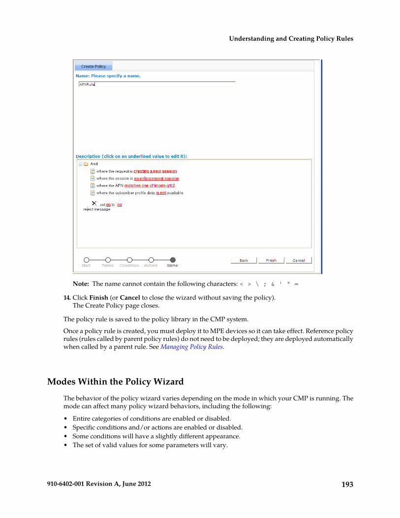
Note: The name cannot contain the following characters: < > \ ; & ' " =
14. Click Finish (or Cancel to close the wizard without saving the policy).The Create Policy page closes.
The policy rule is saved to the policy library in the CMP system.
Once a policy rule is created, you must deploy it to MPE devices so it can take effect. Reference policyrules (rules called by parent policy rules) do not need to be deployed; they are deployed automaticallywhen called by a parent rule. See Managing Policy Rules.
Modes Within the Policy Wizard
The behavior of the policy wizard varies depending on the mode in which your CMP is running. Themode can affect many policy wizard behaviors, including the following:
• Entire categories of conditions are enabled or disabled.• Specific conditions and/or actions are enabled or disabled.• Some conditions will have a slightly different appearance.• The set of valid values for some parameters will vary.
193910-6402-001 Revision A, June 2012
Understanding and Creating Policy Rules

If your policy wizard does not include a category, condition, or action documented here, it means thatthose categories, conditions, or actions are not relevant in your present CMP mode.
Parameters Within Policy Rules
When you are defining policy rules, both the conditions and actions may contain parameters. Parameterslet you customize the specific situation in which a policy rule will be applied. Some conditions andactions may contain multiple parameters. For example, one possible condition is as follows:
where the device will be handling greater than 100 upstream reserved flows
This condition contains four different parameters. The policy wizard displays the parameters usinga red font, with each parameter having a single continuous underline. In this example, greater thanis a single parameter, as is 100, upstream, and reserved.
You can click on any parameter to open a pop-up window that lets you specify the value of thatparameter. Each parameter has a data type associated with it that determines the values that can bespecified: some may be numbers, some may be free-form text, and some may be limited to specificsets of values. For example, the following parameter is limited to a set of text values:
If you have many policies with similar structures, you can consolidate them using policy tables tocapture the differences. To specify a parameter in a rule that uses a policy table, instead of selectinga value click Use Policy Table. For more information on table-driven policies see Managing PolicyTables.
Table 6: Common Parameters defines some common parameter types that are used in many of the policyrules. In this table, the column labeled "Default Text" shows the text value that is displayed in thecondition or action text when they are initially displayed. (This may be different in some instances,but this value is the default.)
There are also many parameter types that are used in only one condition or action. These parametertypes are defined in the sections where those conditions or actions are defined.
Table 6: Common Parameters
Description of ValuesDefault TextParameter Type
Names of applications that have been defined in the CMP.specified nameapp-name
A numeric value that specifies bandwidth in bits per second(bps). You can also type “k”, “K”, “m”,”M”, “g”, or “G” in
#bandwidth
the value to specify the value in units of kilobits, megabits,or gigabits per second instead.
194910-6402-001 Revision A, June 2012
Understanding and Creating Policy Rules

Description of ValuesDefault TextParameter Type
One (or more) of the following:specified class ofclass-of-service
• Background• Conversational• Streaming• Interactive
One of the following:upstreamflow-direction
• upstream• downstream• upstream or downstream
An IPv4 or IPv6 address.specified addressip-address
Any string. This text may contain policy parameters (asdescribed later in this section) that perform parametersubstitution within the message text.
textlog-message
One of the following:matches one ofmatches-op
• matches one of• does not match any of
A comma-separated list of values, where each value is awildcard match pattern that uses the “*” character to match
match-list
zero or more characters and the “?” character matches exactlyone character.
A numeric value. In some circumstances, the numeric valuemay be required to fall within a certain range of valid values.
#number
One of the following:greater thanoperator
• greater than or equal to• greater than• less than or equal to• less than• equal to• not equal to
One of the following:isoperator-binary
• is• is not
One of the following:greater thanoperator-greater
• greater than or equal to• greater than
195910-6402-001 Revision A, June 2012
Understanding and Creating Policy Rules

Description of ValuesDefault TextParameter Type
One of the following:less thanoperator-less
• less than or equal to• less than
An integer value between 0 and 100; for certain values, anextended, non-integer percentage that can exceed 100 (forexample, 102.4%).
#percent
One of the following:upstreamqos-direction
• upstream• downstream
One or more of the following:reservedqos-status
• reserved• committed
A numeric value that specifies time in units of seconds.#seconds
Any string.specifiedstring
An IPv4 subnet in CIDR notation (for example, 1.2.3.0/24);specified subnetsubnet
or an IPv6 subnet (for example, fc00::1006/64).
Conditions Available for Writing Policy Rules
The policy wizard supports a large number of conditions that can be used for constructing policyrules. To help you find the conditions you want, the conditions are organized into different categories,which are summarized in Table 7: Policy Condition Categories.
Table 7: Policy Condition Categories
DescriptionCategory
Conditions that are based on information that is explicitly contained within orrelated to the protocol message (request) that triggered the policy rule execution.
Request
Conditions related to the application associated with the request.Application
Conditions related to the specific network device for which the policy rule isbeing evaluated. This includes conditions based on the network device type,as well as those that refer to specific unique identifiers for network devices.
Network DeviceIdentity
196910-6402-001 Revision A, June 2012
Understanding and Creating Policy Rules

DescriptionCategory
Conditions related to the calculated usage for the network device for whichthe policy rule is being evaluated. This usage includes device-level tracking ofboth bandwidth and flow/session counts.
Network DeviceUsage
Conditions that are based on information associated with networks that includemobile subscribers (such as a wireless network).
Mobility
Conditions related to the subscriber, or subscriber account, that is associatedwith the protocol message that triggered the policy rule execution. This includessubscriber-level and account-level tracking of usage.
User
Conditions related to subscriber propertiesUser State
Conditions related to the context in which a policy is evaluated.Policy ContextProperties
Conditions related to the time at which the policy rules are being executed.Time of Day
The conditions that are included within each of these categories are described in the sections thatfollow. Conditions are listed in alphabetical order. The parameters that can be modified within eachcondition are also summarized, with detailed descriptions of these parameters being described laterin this section.
Request Conditions
Request conditions are based on information that is explicitly contained within, or related to, theprotocol message (request) that triggered the policy rule execution. The following conditions areavailable.
where at least one Filter-ID AVP existsCondition
Tests whether the current request contains one or more Filter-ID AVPs.Description
where at least one Final-Unit-Action matches Final-Unit-Action to matchCondition
where at least one Final-Unit-Action matches actionParameters
action — One of the following:
• ACTION_TERMINATE• ACTION_REDIRECT• ACTION_RESTRICT_ACCESS
Tests whether the current request contains an FUI AVP matching the specifiedFinal Unit Action (FUA).
Description
where at least one Final-Unit-Indication AVP existsCondition
Tests whether the current request contains one or more Final-Unit-Indication(FUI) AVPs.
Description
where Filter-ID AVP does not existCondition
Tests whether the current request contains no Filter-ID AVPs.Description
197910-6402-001 Revision A, June 2012
Understanding and Creating Policy Rules

where the AF-Application-ID matches one of specified value(s)Condition
where the AF-Application-ID matches one of csvParameters
csv — Comma-separated list of text values.
Selects protocol messages based on the Diameter AF Application Identifier field.A valid AF Application identifier is any string describing the application, forexample VoIP or streaming.
Description
where the bearer usage is GeneralCondition
where the bearer usage is bearer-usageParameters
bearer-usage — One or more of the following:
• General• IMS Signaling
Selects protocol message based on the user or equipment information.Description
where the enforcement session is an IP-CAN sessionCondition
where the enforcement session is enforcement-session-typeParameters
enforcement-session-type — One or more of the following:
• an IP-CAN session• a gateway control session
Distinguishes between different types of enforcement sessions.Description
where the event trigger is one of specified trigger(s)Condition
where the event trigger is one of event-triggerParameters
event-trigger — One or more of the following:
• SGSN_CHANGE• LOSS_OF_BEARER• RECOVERY_OF_BEARER• GW_PCEF_MALFUNCTION• MAX_NR_BEARERS_REACHED• QOS_CHANGE_EXCEEDING_AUTHORIZATION• ECGI_CHANGE• RAI_CHANGE• TAI_CHANGE• USER_LOCATION_CHANGE• OUT_OF_CREDIT• REALLOCATION_OF_CREDIT• REVALIDATION_TIMEOUT• UE_IP_ADDRESS_ALLOCATE• UE_IP_ADDRESS_RELEASE• DEFAULT_EPS_BEARER_QOS_CHANGE• AN_GW_CHANGE
198910-6402-001 Revision A, June 2012
Understanding and Creating Policy Rules
• SUCCESSFUL_RESOURCE_ALLOCATION• PCF_CHANGE• LOSS_OF_FLOW• RECOVERY_OF_FLOW• AGW_MALFUNCTION• ACCESS_NETWORK_PHYSICAL_ACCESS_ID_CHANGE• QOS_CHANGE• RAT_CHANGE• TFT_CHANGE• PLMN_CHANGE• IP_CAN_CHANGE• RESOURCES_LIMITATION• USAGE_TIME_ZONE_CHANGE• USAGE_THRESHOLD_REACHED• USAGE_REPORT• CELL_CONGESTED• CELL_CLEAR• SERVICE_FLOW_DETECTION
Selects protocol messages based on the event trigger.Description
where the Filter-ID in the Final-Unit-Indication AVP as Policy ConditionCondition
Provides PCRF support for constructing and executing policy conditions andrules. The Filter-ID value(s) are received in the Final-Unit-Indication AVP.
Description
where the Filter-Ids in the Final-Unit-Indication AVPs match one or more ofFilter-Ids to match and the search type is MATCH ALL FROM ANY REPORT
Condition
where the Filter-Ids in the Final-Unit-Indication AVPs match one or more of csvand the search type is search
Parameters
csv — A comma-separated list of text values
search — One of the following:
• MATCH_ALL_FROM_ANY_REPORT• MATCH_NONE• MATCH_ANYONE• MATCH_ALL_FROM_ONE_REPORT
Provides a minimum of at least one Filter-ID in the message that must matchthe provisioned value or list. Each ID in the provisioned list must match whatis in the message.
Description
where Final-Unit-Indication AVP does not existCondition
Allows for a condition that will determine if the PCRF current request containsa Final-Unit-Indication (FUI) AVP.
Description
where the flow is an application flowCondition
where the flow is flow-typeParameters
199910-6402-001 Revision A, June 2012
Understanding and Creating Policy Rules

flow-type — One or more of the following:
• an application flow (the default)• a UE flow• the default flow
Selects protocol messages based on the type of flow.Description
where the flow media type is one of specified type(s)Condition
where the flow media type is one of media-typeParameters
media-type — One or more of the following:
• Audio• Video• Data• Application• Control• Text• Message• Other
Selects protocol messages based on the flow’s media type.Description
where the flow media type specified type(s) is one of specified status(s)Condition
where the flow media type media-type is one of media-statusParameters
media-type — One or more of the following media types:
• Audio• Video• Data• Application• Control• Text• Message• Other
media-status — One or more of the following status types:
• Enabled• Enabled Uplink• Enabled Downlink• Disabled• Removed
Selects protocol messages that matches the flow's media type and status type.Description
where the flow media types Matches specified type(s)Condition
200910-6402-001 Revision A, June 2012
Understanding and Creating Policy Rules

where the flow media type matches one of specified typeParameters
specified type — One or more of the following media types:
• Audio• Video• Data• Application• Control• Text• Message• Other
Selects protocol messages that match the flow's media type.Description
where the flow packet filter matches one of specified packet filter(s)Condition
where the flow packet filter matches-op match-listParameters
matches-op — See common parameters.
match-list — See common parameters.
Selects protocol messages based on the packet filters. The packet filters useIPFilterRule format, as defined in the Diameter base protocol (RFC 3588). Forexample: permit in ip from 10.0.0.1 to 10.0.0.2 5060.
Description
where the flow usage is one of specified usage(s)Condition
where the flow usage is flow-usage-typeParameters
flow-usage-type — One or more of the following:
• No Information• RTCP• AF Signaling
Selects protocol messages based on the flow usage.Description
where the IP-CAN bearer is the primary bearerCondition
where the IP-CAN bearer is bearer-typeParameters
bearer-type — One or more of the following:
• the primary bearer• a secondary bearer
Selects protocol messages based on the IP-CAN bearer type.Description
where the PCC rule being reinstalled contains one of specified rule name(s)and the retry is the final attempt
Condition
where the PCC rule being reinstalled contains one of csv and the retryoperator-binary the final attempt
Parameters
csv — Comma-separated list of text values.
201910-6402-001 Revision A, June 2012
Understanding and Creating Policy Rules
operator-binary — One of the following:
• is• is not
Reinstalls the specified PCC rule depending on whether this is the final retryattempt or not.
Description
where the QoS parameters in the flow are equal to specified valueCondition
where the QoS parameters in the flow are equal to profile-paramParameters
profile-param — Names of profile parameters that are derived from internalrepresentations of protocol messages. For the specific meaning of the fields,consult the specific protocol specifications.
• Diameter AF Flow-Description• Diameter AF Flow-Status• Diameter AF Flow-Usage• Diameter AF Maximum-Authorized-Data-Rate• Diameter AF Media-Type• Diameter AF PacketTime• Diameter AF QCI• Diameter AF Reservation-Priority• Diameter AF RTCP RR-Bandwidth• Diameter AF RTCP RS-Bandwidth• Diameter APN-Aggregate-Max-Bitrate-DL• Diameter APN-Aggregate-Max-Bitrate-UL• Diameter Bearer ARP Priority Level• Diameter Bearer Guaranteed-Bitrate-DL• Diameter Bearer Guaranteed-Bitrate-UL• Diameter Bearer Maximum-Requested-Bandwidth-DL• Diameter Bearer Maximum-Requested-Bandwidth-UL• Diameter Bearer QCI• Diameter Default EPS ARP Preemption Capability• Diameter Default EPS ARP Preemption Vulnerability• Diameter Default EPS ARP Priority Level• Diameter Default EPS Bearer QCI• Diameter Enforcement Session Bearer Control Mode Selection• Diameter Enforcement Session Event Triggers• Diameter Credit-Control Session Trigger Type• Diameter Flow-Status• Diameter IP-CAN Session Bearer Control Mode• Diameter IP-CAN Session Default Offline Charging• Diameter IP-CAN Session Default Online Charging• Diameter IP-CAN Session Primary OCS• Diameter IP-CAN Session Primary OFCS• Diameter IP-CAN Session Secondary OCS• Diameter IP-CAN Session Secondary OFCS
202910-6402-001 Revision A, June 2012
Understanding and Creating Policy Rules

• Diameter IP-CAN Session Usage Monitoring• Diameter IP-CAN Session Usage Reporting• Diameter PCC Rule AF-Charging-Identifier• Diameter PCC Rule ARP Preemption Capability• Diameter PCC Rule ARP Preemption Vulnerability• Diameter PCC Rule ARP Priority Level• Diameter PCC Rule Flow-Status• Diameter PCC Rule Guaranteed-Bitrate-DL• Diameter PCC Rule Guaranteed-Bitrate-UL• Diameter PCC Rule Maximum-Requested-Bandwidth-DL• Diameter PCC Rule Maximum-Requested-Bandwidth-UL• Diameter PCC Rule Metering-Method• Diameter PCC Rule Monitoring-Key• Diameter PCC Rule Offline Charging• Diameter PCC Rule Online Charging• Diameter PCC Rule Precedence• Diameter PCC Rule QCI• Diameter PCC Rule Rating-Group• Diameter PCC Rule Reporting-Level• Diameter PCC Rule Service-Identifier
Selects protocol messages based on values of specific parameters in the protocolmessage for which there may not be an explicit condition already.
Description
where the quota is requestedCondition
where the quota is quota-change-typeParameters
quota-change-type — One or more of the following:
• requested• debited
Selects protocol messages based on the type of change to the quota. See ManagingQuotas for information about defining quotas.
Description
where the quota usage rating conditions changed trigger is one of specifiedvalues
Condition
where the quota usage rating conditions changed trigger is one of trigger-typeParameters
trigger-type — One or more of the following:
• CHANGE_IN_SGSN_IP_ADDRESS• CHANGE_IN_QOS• CHANGE_IN_LOCATION• CHANGE_IN_RAT• CHANGE_IN_QOS_TRAFFIC_CLASS• CHANGE_IN_QOS_RELIABILITY_CLASS• CHANGE_IN_QOS_DELAY_CLASS• CHANGE_IN_QOS_PEAK_THROUGHPUT
203910-6402-001 Revision A, June 2012
Understanding and Creating Policy Rules

• CHANGE_IN_QOS_PRECEDENCE_CLASS• CHANGE_IN_QOS_MEAN_THROUGHPUT• CHANGE_IN_QOS_MAXIMUM_BIT_RATE_FOR_UPLINK• CHANGE_IN_QOS_MAXIMUM_BIT_RATE_FOR_DOWNLINK• CHANGE_IN_QOS_RESIDUAL_BER• CHANGE_IN_QOS_SDU_ERROR_RATIO• CHANGE_IN_QOS_TRANSFER_DELAY• CHANGE_IN_QOS_TRAFFIC_HANDLING_PRIORITY• CHANGE_IN_QOS_GUARANTEED_BIT_RATE_FOR_UPLINK• CHANGE_IN_QOS_GUARANTEED_BIT_RATE_FOR_DOWNLINK• CHANGE_IN_LOCATION_MCC• CHANGE_IN_LOCATION_MNC• CHANGE_IN_LOCATION_RAC• CHANGE_IN_LOCATION_LAC• CHANGE_IN_LOCATION_CELL_ID• CHANGE_IN_MEDIA_COMPOSITION• CHANGE_IN_PARTICIPANTS_NMB• CHANGE_IN_THRSHLD_OF_PARTICIPANTS_NMB• CHANGE_IN_USER_PARTICIPATING_TYPE• CHANGE_IN_SERVICE_CONDITION• CHANGE_IN_SERVING_NODE
Selects protocol messages based on the quota usage rating conditions changedtrigger. See Managing Quotas for information about defining quotas.
Description
where the quota usage reporting reason is one of specified valuesCondition
where the quota usage reporting reason is one of reporting-reasonParameters
reporting-reason — One or more of the following:
• threshold reached• quota holding time reached• final reporting• quota exhausted• validity time expired• other quota type reported• rating condition changed• forced reauthorization• pool exhausted
Selects protocol messages based on the quota usage reporting reason. SeeManaging Quotas for information about defining quotas.
Description
where the request AVP name existsCondition
where the request AVP avp accessibilityParameters
204910-6402-001 Revision A, June 2012
Understanding and Creating Policy Rules

avp — AVP in for format name:vendorID, or a full path[avp_name1]:vendorID.[avp_name2]:vendorID... for the members of the groupedAVPs
accessibility — One of the following:
• exists• does not exist
Checks for the presence or absence of the third-party AVP in an incomingDiameter message.
Note: The condition supports both loaded base Diameter AVPs and third-partyAVPs.
Description
where the request AVP name is numerically equal to valueCondition
where the request AVP avp is numerically operator valueParameters
avp — AVP in for format name:vendorID, or a full path[avp_name1]:vendorID.[avp_name2]:vendorID... for the members of the groupedAVPs
operator — See common parameters.
value — String value.
Compares a numerical AVP value against a specified number or policy contextnumber variable value.
Note: The condition supports both loaded base Diameter AVPs and third-partyAVPs.
Description
where the request AVP name value contains one of value(s)Condition
where the request AVP avp value containment csvParameters
avp — AVP in for format name:vendorID, or a full path[avp_name1]:vendorID.[avp_name2]:vendorID... for the members of the groupedAVPs
containment — One of the following:
• contains one of• does not contain any of
csv — Comma-separated list of text values.
Performs a lookup of the sub-strings in the AVP value. It is possible to checkmultiple sub-string entries at once. If the operation type is changed, you can
Description
check the opposite scenario, which would not include any of the providedsub-strings.
Note: The condition supports both loaded base Diameter AVPs and third-partyAVPs.
where the request AVP name value matches one of value(s)Condition
205910-6402-001 Revision A, June 2012
Understanding and Creating Policy Rules

where the request AVP avp value matches-op csvParameters
avp — AVP in for format name:vendorID, or a full path[avp_name1]:vendorID.[avp_name2]:vendorID... for the members of the groupedAVPs
matches-op — See common parameters.
csv — Comma-separated list of text values.
Compares the specified AVP value with the values or variables from the specifiedlist. The condition is where the request AVP name value matches one of value(s).
Description
The values can be evaluated for equality as well as inequality. To evaluate AVPvalue for inequality, the condition matches one must be changed to does not matchany of.
Note: The condition supports both loaded base Diameter AVPs and third-partyAVPs.
where the request is creating a new flowCondition
where the request is change-typeParameters
change-type — One or more of the following:
• creating a new flow• modifying an existing flow• provisioning a default flow• terminating an existing flow
Distinguishes between protocol messages based on the type of operation beingperformed on the flow.
Description
where the request is creating a new sessionCondition
where the request is request-typeParameters
request-type — One or more of the following:
• creating a new session• modifying an existing session• re-authorizing an existing session• terminating an existing session
Distinguishes between protocol messages based on the type of operation beingperformed on the subscriber's session.
Description
where the request is for reserved bandwidthCondition
where the request is for qos-status bandwidthParameters
qos-status — See common parameters.
Distinguishes between protocol messages based on the type of bandwidth thatis being updated.
Description
where the request is for upstream bandwidthCondition
where the request is for qos-direction bandwidthParameters
206910-6402-001 Revision A, June 2012
Understanding and Creating Policy Rules
qos-direction — See common parameters.
Distinguishes between protocol messages based on the direction of bandwidththat is being updated.
Description
where the requested guaranteed upstream bandwidth is greater than # bpsCondition
where the requested guaranteed flow-direction bandwidth is operator bandwidthbps
Parameters
flow-direction — See common parameters.
operator — See common parameters.
bandwidth — See common parameters.
Selects protocol messages based on the amount of bandwidth being requestedin a specific direction relative to a numeric value.
Description
where the requested maximum upstream bandwidth is greater than # bpsCondition
where the requested maximum flow-direction bandwidth is operator bandwidthbps
Parameters
flow-direction — See common parameters.
operator — See common parameters.
bandwidth — See common parameters.
Selects protocol messages based on the maximum amount of bandwidth beingrequested in a specific direction relative to a numeric value.
Description
where the requested media component description reservation priority is oneof specified
Condition
where the requested media component description reservation priority is oneof priority
Parameters
priority — One or more of the following:
• DEFAULT• PRIORITY_ONE• PRIORITY_TWO• PRIORITY_THREE• PRIORITY_FOUR• PRIORITY_FIVE• PRIORITY_SIX• PRIORITY_SEVEN
Selects Rx protocol messages based on the requested media componentdescription reservation priority.
Description
where the requested QCI is one of specifiedCondition
where the requested QCI is one of class-of-serviceParameters
class-of-service — One or more of the following:
• 1 (Conversational speech)
207910-6402-001 Revision A, June 2012
Understanding and Creating Policy Rules

• 2 (Conversational)• 3 (Streaming speech)• 4 (Streaming)• 5 (Interactive with priority 1 signalling)• 6 (Interactive with priority 1)• 7 (Interactive with priority 2)• 8 (Interactive with priority 3)• 9 (Background)
Selects protocol messages based on the QoS class identifier (QCI).Description
where the requested quota is one of select quotaCondition
where the requested quota is one of quota-nameParameters
quota-name — Names of quotas that are defined in the CMP.
Selects protocol messages based on the requested quotas. See Managing Quotasfor information about defining quotas.
Description
where the requested rating group is one of select rating groupCondition
where the requested rating group is one of rating-group-nameParameters
rating-group-name — Names of rating groups that are defined in the CMP.
Selects protocol messages based on the subscriber’s rating group. See ManagingServices and Rating Groups for information on services.
Description
where the requested service(s) are select serviceCondition
where the requested services are service-profile-nameParameters
service-profile-name — Names of service profiles that are defined in the CMP.
Selects protocol messages based on the services in the request. See ManagingServices and Rating Groups for information on services.
Description
where the requested session reservation priority is one of specifiedCondition
where the requested session reservation priority is one of priorityParameters
priority — One or more of the following:
• DEFAULT• PRIORITY_ONE• PRIORITY_TWO• PRIORITY_THREE• PRIORITY_FOUR• PRIORITY_FIVE• PRIORITY_SIX• PRIORITY_SEVEN
Selects Rx protocol messages based on the requested session reservation priority.Description
where the requested upstream APN aggregate maximum bitrate is greaterthan # bps
Condition
208910-6402-001 Revision A, June 2012
Understanding and Creating Policy Rules

where the requested flow-direction APN aggregate maximum bitrate is operatorbandwidth bps
Parameters
flow-direction — See common parameters.
operator — See common parameters.
bandwidth — See common parameters.
Selects protocol messages based on the maximum bitrate being requested in aspecific direction relative to a numeric value.
Description
where the rule report contains one of specified rule name(s) and the final unitaction is one of ACTION_TERMINATE and the rule status is active
Condition
where the rule report contains one of csv and the final unit action is one of actionand the rule status is field
Parameters
csv — Comma-separated list of text values.
action — One of the following:
• ACTION_TERMINATE• ACTION_REDIRECT• ACTION_RESTRICT_ACCESS
field — One of the following:
• active• inactive• temporarily_inactive
Selects protocol messages based on the rule name, reported final unit action,and status received in a rule report.
Description
where the rule report contains one of specified rule name(s) and the rule statusis active
Condition
where the rule report contains one of csv and the rule status is fieldParameters
csv — Comma-separated list of text values.
field — One of the following:
• active• inactive• temporarily_inactive
Selects protocol messages based on the rule name and status received in a rulereport.
Description
where the rule report contains one of specified rule name(s) and the rule statusis active and the rule failure code is one of specified failure code(s)
Condition
where the rule report contains one of csv and the rule status is field and the rulefailure code is one of failcode
Parameters
csv — Comma-separated list of text values.
209910-6402-001 Revision A, June 2012
Understanding and Creating Policy Rules

field — One of the following:
• active• inactive• temporarily_inactive
failcode — One of the following:
• UNKNOWN_RULE_NAME• RATING_GROUP_ERROR• SERVICE_IDENTIFICATION_ERROR• GW_PCEF_MALFUNCTION• RESOURCES_LIMITATION• MAX_NR_BEARERS_REACHED• UNKNOWN_BEARER_ID• MISSING_BEARER_ID• MISSING_FLOW_DESCRIPTION• RESOURCE_ALLOCATION_FAILURE• UNSUCCESSFUL_QOS_VALIDATION
Selects protocol messages based on the rule name, status, and failure codereceived in a rule report.
Description
where the rule report contains one of specified rule name(s) and the rule statusis active and the rule failure code is one of specified failure code(s) and themaximum retry count is reached
Condition
where the rule report contains one of csv and the rule status is field and the rulefailure code is one of failcode and the maximum retry count operator-binary reached
Parameters
csv — Comma-separated list of text values.
field — One of the following:
• active• inactive• temporarily_inactive
failcode — One of the following:
• UNKNOWN_RULE_NAME• RATING_GROUP_ERROR• SERVICE_IDENTIFICATION_ERROR• GW_PCEF_MALFUNCTION• RESOURCES_LIMITATION• MAX_NR_BEARERS_REACHED• UNKNOWN_BEARER_ID• MISSING_BEARER_ID• MISSING_FLOW_DESCRIPTION• RESOURCE_ALLOCATION_FAILURE• UNSUCCESSFUL_QOS_VALIDATION
210910-6402-001 Revision A, June 2012
Understanding and Creating Policy Rules

operator-binary — One of the following:
• is• is not
Selects protocol messages based on the rule name, status, failure code, and retrycount received in a rule report.
Description
where the select type is contained in Match List(s) select list(s)Condition
where the field is contained in Match List(s) match-listParameters
field — One or more of the following:
• Serving Gateway Address — IP address of the serving gateway• APN — Access Point Name• User Equipment Identity• USER IMSI — User International Mobile Subscriber Identity• USER E.164 — User E164 phone number• User SIP URI — User Session Initiation Protocol Uniform Resource Identifier• User NAI — User Network Access Identifier• Endpoint IP Address — IP address of the endpoint• Serving MCC-MNC — Serving Mobile Country Code, Mobile Network
Code• Cell Identifier• Location Area Code — Unique identifier of a location area• Serving Area Code• Routing Area Code — Identifies a routing area within a location area• Routing Area Identifier — Combination of the location area code and routing
area code• Tracking Area Code• E-UTRAN Cell Identifier — Identifies cells within a PLMN• Entitlements — A defined entitlement
match-list — See common parameters.
Selects protocol messages based on whether the messages or associated sessionsmatch any of the values in a match list. Any of the types can be selected in
Description
combination. The order will match the list from top to bottom. See ManagingMatch Lists for information about defining match lists.
where the USER IMSI,LAC,SAC is contained in Match List(s) select lists(s)
Example
where the select type is not contained in Match List(s) select list(s)Condition
where the field is not contained in Match List(s) match-listParameters
field — One or more of the following:
• Serving Gateway Address• APN — Access Point Name
211910-6402-001 Revision A, June 2012
Understanding and Creating Policy Rules

• User Equipment Identity• USER IMSI — User International Mobile Subscriber Identity• USER E.164 — User E164 phone number• User SIP URI — User Session Initiation Protocol Uniform Resource Identifier• User NAI — User Network Access Identifier• Endpoint IP Address — IP address of the endpoint• Serving MCC-MNC — Serving Mobile Country Code, Mobile Network
Code• Cell Identifier• Location Area Code — Unique identifier of a location area• Serving Area Code• Routing Area Code — Identifies a routing area within a location area• Routing Area Identifier — Combination of the location area code and routing
area code• Tracking Area Code• E-UTRAN Cell Identifier — Identifies cells within a PLMN• Entitlements — A defined entitlement
match-list — See common parameters.
Selects protocol messages based on whether the messages or associated sessionsdo not match any of the values in a match list. Any of the types can be selected
Description
in combination. The order will match the list from top to bottom. See ManagingMatch Lists for information about defining match lists.
where the USER IMSI,LAC,RAC is not contained in Match List(s) select lists(s)
Example
where the service info status is one of specifiedCondition
where the service info status is one of statusParameters
status — One or more of the following:
• FINAL_SERVICE_INFORMATION• PRELIMINARY_SERVICE_INFORMATION
Selects Rx protocol messages based on the service information status.Description
where the Service-URN is one of specified value(s)Condition
where the Service-URN is one of csvParameters
csv — A comma-separated list of text values
Selects Rx protocol messages based on the value of the Service-URN field.Description
where the session is an enforcement sessionCondition
where the session is session-typeParameters
session-type — One of the following:
• an enforcement session• an application session
212910-6402-001 Revision A, June 2012
Understanding and Creating Policy Rules

• a credit control session
Distinguishes between protocol messages that are operating on different sessions.Description
where the TDF-Application-Identifier matches one of specified TDFapplication id(s)
Condition
where the TDF-Application-Identifier matches one of csvParameters
csv — Comma-separated list of text values.
Selects protocol messages based on the Traffic Detection Function (TDF)Application Identifier field. A valid TDF application identifier is any stringdescribing the TDF.
Description
Application Conditions
Application conditions are related to the application associated with the request. See ManagingApplication Profiles for information on creating and managing application profiles. The followingconditions are available.
where the application is latency sensitiveCondition
Triggers a policy when the associated application is latency sensitive (can beset in the CMP when applications are defined).
Description
where the application is one of specified nameCondition
where the application operator-binary one of app-nameParameters
operator-binary — See common parameters.
app-name — Names of applications that are defined in the CMP.
Triggers a policy based on the associated application.Description
where the application will be using greater than # bps upstream reservedbandwidth
Condition
where the application will be using operator-greater bandwidth bps qos-directionqos-status bandwidth
Parameters
operator-greater — See common parameters.
bandwidth — See common parameters.
qos-direction — See common parameters.
qos-status — See common parameters.
Triggers a policy based on the total amount of bandwidth used by theassociated application as it relates to a defined threshold. This can be further
Description
qualified by both the direction and allocation status of the bandwidth. Thetotal represents the amount of bandwidth that is allocated if the current requestis approved.
where the application will be using greater than # upstream reserved flowsCondition
where the application will be using operator-greater bandwidth qos-directionqos-status flows
Parameters
213910-6402-001 Revision A, June 2012
Understanding and Creating Policy Rules

operator-greater — See common parameters.
bandwidth — See common parameters.
qos-direction — See common parameters.
qos-status — See common parameters.
Triggers a policy based on the total number of flows used by the associatedapplication as it relates to a defined threshold. This can be further qualified
Description
by both the direction and allocation status of the flows. The total representsthe number of flows that is allocated if the current request is approved.
where there is no application associated with the requestCondition
Triggers a policy when there is no associated application.Description
Network Device Identity Conditions
Network Device Identity conditions are related to the specific network device for which the policyrule is being evaluated. This includes conditions based on the network device type, as well as thosethat refer to specific unique identifiers for network devices. See Managing Network Elements forinformation on defining the network elements available. The following conditions are available.
where the device name matches one of specified name(s)Condition
where the device name matches one of match-listParameters
match-list — See common parameters.
Triggers a policy based on whether the device name matches one or morewildcard match patterns.
Description
where the device type is specified typeCondition
where the device type operator-binary device-typeParameters
operator-binary — See common parameters.
device-type — One or more of the following:
• PDSN• GGSN• HomeAgent• HSGW• PGW• SGW• DPI
Triggers a policy based on the device type for which it is evaluated.Description
where the endpoint IP address is in specified subnetCondition
where the endpoint IP address is in subnetParameters
subnet — See common parameters.
Triggers a policy that is only evaluated for endpoints whose IP address fallswithin a specific subnet.
Description
214910-6402-001 Revision A, June 2012
Understanding and Creating Policy Rules

where the endpoint IP address is specified addressCondition
where the endpoint IP address is ip-addressParameters
ip-address — See common parameters.
Triggers a policy that is only evaluated for a specific endpoint (based on itsIP address).
Description
where the network element name matches one of specified name(s)Condition
where the network element name matches-op csvParameters
matches-op — See common parameters.
Triggers a policy based on the name of the network element for which it isbeing evaluated.
Description
where the network element type is specified typeCondition
where the network element type operator-binary element-typeParameters
operator-binary — See common parameters.
element-type — One or more of the following:
• GGSN• PDSN• HomeAgent• HSGW• PGW• SGW• DPI
Triggers a policy based on the type of network element for which it is beingevaluated. Note that if the policy is being evaluated for a device that is not
Description
a network element but is contained within a network element (such as aninterface within a router) then the network element “container” is used asthe basis of comparison.
where the network element's description field is equal to specifieddescription(s)
Condition
where the network element's description field is equal to descriptionParameters
description — string.
Triggers a policy that is only evaluated if the Description field of the networkelement matches the specified string.
Description
where the User Equipment ESN matches one of specified ESN value(s)Condition
where the User Equipment ESN matches-op match-listParameters
matches-op — See common parameters.
match-list — See common parameters.
Triggers a policy that is only evaluated for one or more specific ESN values(based on matching wildcard patterns). A valid ESN value has eight
Description
215910-6402-001 Revision A, June 2012
Understanding and Creating Policy Rules

hexadecimal digits, representing the 32 bits of the ESN; for example:A01F3D45.
where the User Equipment IMEISV matches one of specified IMEISVvalue(s)
Condition
where the user equipment IMEISV matches-op match-listParameters
matches-op — See common parameters.
match-list — See common parameters.
Triggers a policy that is only evaluated for one or more specific IMEISVvalues (based on matching wildcard patterns). A valid IMEISV value has16 decimal digits, as defined in the 3GPP TS 23.003 standard.
Description
where the User Equipment MEID matches one of specified MEID value(s)Condition
where the User Equipment MEID matches-op match-listParameters
matches-op — See common parameters.
match-list — See common parameters.
Triggers a policy that is only evaluated for one or more specific MEID values(based on matching wildcard patterns). A valid MEID value has 14hexadecimal characters; for example: 123456789abcde.
Description
Network Device Usage Conditions
Network Device Usage conditions are related to the calculated usage for the network device for whichthe policy rule is being evaluated. This usage includes device-level tracking of both bandwidth andflow/session counts. The following conditions are available.
where the device will be handling greater than # bps upstream reservedbandwidth
Condition
where the device will be handling operator bandwidth bps qos-direction qos-statusbandwidth
Parameters
operator — See common parameters.
bandwidth — See common parameters.
qos-direction — See common parameters.
qos-status — See common parameters.
Triggers a policy based on the total amount of bandwidth used by the currentdevice as it relates to a defined threshold. This can be further qualified by both
Description
the direction and allocation status of the bandwidth. The total represents thebandwidth that is allocated if the current request is approved.
where the device will be handling greater than # bps upstream reservedbandwidth in total for specified application
Condition
where the device will be handling operator bandwidth bps qos-direction qos-statusbandwidth in total for app-name
Parameters
operator — See common parameters.
216910-6402-001 Revision A, June 2012
Understanding and Creating Policy Rules

bandwidth — See common parameters.
qos-direction — See common parameters.
qos-status — See common parameters.
app-name — Names of the applications that are defined in the CMP.
Triggers a policy based on the total amount of bandwidth allocated for specificapplications by the current device as it relates to a defined threshold. This can be
Description
further qualified by both the direction and allocation status of the bandwidth. Thetotal represents the bandwidth that is allocated if the current request is approved.
where the device will be handling greater than # percent of upstream reservedcapacity
Condition
where the device will be handling operator percent percent of qos-direction qos-statuscapacity
Parameters
operator — See common parameters.
percent — See common parameters.
qos-direction — See common parameters.
qos-status — See common parameters.
Triggers a policy based on the percent of bandwidth capacity used by the currentdevice as it relates to a defined threshold. This can be further qualified by both
Description
the direction and allocation status of the bandwidth. The total represents thebandwidth that is allocated if the current request is approved.
where the device will be handling greater than # percent of upstream reservedcapacity for specified application
Condition
where the device will be handling operator percent percent of qos-direction qos-statuscapacity for app-name
Parameters
operator — See common parameters.
percent — See common parameters.
qos-direction — See common parameters.
qos-status — See common parameters.
app-name — Names of the applications that are defined in the CMP.
Triggers a policy based on the percent of bandwidth capacity allocated for specificapplications by the current device as it relates to a defined threshold. This can be
Description
further qualified by both the direction and allocation status of the bandwidth. Thetotal represents the bandwidth that is allocated if the current request is approved.
where the device will be handling greater than # upstream reserved flowsCondition
where the device will be handling operator number qos-direction qos-status flowsParameters
operator — See common parameters.
number — See common parameters.
qos-direction — See common parameters.
217910-6402-001 Revision A, June 2012
Understanding and Creating Policy Rules

qos-status — See common parameters.
Triggers a policy based on the total number of flows used by the current deviceas it relates to a defined threshold. This can be further qualified by both the
Description
direction and allocation status of the flows. The total represents the number offlows that are allocated if the current request is approved.
where the device will be handling greater than # upstream reserved flows intotal for specified application
Condition
where the device will be handling operator number qos-direction qos-status flows intotal for app-name
Parameters
operator — See common parameters.
number — See common parameters.
qos-direction — See common parameters.
qos-status — See common parameters.
app-name — Names of the applications that are defined in the CMP.
Triggers a policy based on the total number of flows for specific applications usedby the current device as it relates to a defined threshold. This can be further
Description
qualified by both the direction and allocation status of the flows. The totalrepresents the number of flows that are allocated if the current request is approved.
Mobility Conditions
Mobility conditions are based on information associated with networks that include mobile subscribers(such as a wireless network). The following conditions are available.
where network initiated requests are supportedCondition
where network initiated requests are network-request-supportParameters
network-request-support — One of the following:
• not supported• supported
Triggers a policy that is only evaluated when network initiated requests areor are not supported.
Description
where the APN matches one of specified APN value(s)Condition
where the APN matches-op match-listParameters
matches-op — See common parameters.
match-list — See common parameters.
Triggers a policy that is only evaluated for one or more specific APN values(based on matching wildcard patterns). A valid APN value is any domainname; for example: network.operator.com.
Description
where the BSID matches one of specified BSID value(s)Condition
where the BSID matches-op match-listParameters
218910-6402-001 Revision A, June 2012
Understanding and Creating Policy Rules

matches-op — See common parameters.
match-list — See common parameters.
Triggers a policy that is only evaluated for one or more specific BSID values(based on matching wildcard patterns).
Description
where the Cell Identifier matches one of specified CI value(s)Condition
where the Cell Identifier matches-op match-listParameters
matches-op — See common parameters.
match-list — See common parameters.
Triggers a policy that is only evaluated for one or more specific Cell Identifiervalues (based on matching wildcard patterns). A valid Cell Identifier is aninteger between 0 and 65535.
Description
where the cell state is specifiedCondition
where the cell state is stateParameters
state — One of the following:
• congested• not congested
Triggers a policy that is evaluated based on the level of congestion in thecell.
Description
where the E-UTRAN Cell Identifier matches one of specified ECI value(s)Condition
where the E-UTRAN Cell Identifier matches-op match-listParameters
matches-op — See common parameters.
match-list — See common parameters.
Triggers a policy that is only evaluated for one or more specific E-UTRANCell Identifier values (based on matching wildcard patterns).
Description
where the IP address of the Serving Gateway matches one of specifiedaddress(es)
Condition
where the IP address of the Serving Gateway matches-op match-listParameters
matches-op — See common parameters.
match-list — See common parameters.
Triggers a policy that is only evaluated for one or more specific ServingGateway addresses (based on matching wildcard patterns).
Description
where the IP-CAN type is specifiedCondition
where the IP-CAN type is ip-can-typeParameters
ip-can-type — One or more of the following:
• 3GPP GPRS• 3GPP EPS• 3GPP2
219910-6402-001 Revision A, June 2012
Understanding and Creating Policy Rules

• WiMAX• DOCSIS• xDSL
Triggers a policy that is only evaluated for a protocol message with a specificIP-CAN type.
Description
where the IP address of the Serving PCF matches one of specifiedaddress(es)
Condition
where the IP address of the Serving PCF matches-op match-listParameters
matches-op — See common parameters.
match-list — See common parameters.
Triggers a policy that is only evaluated for one or more specific Serving PCFaddresses (based on matching wildcard patterns).
Description
where the IP address of the Home Agent matches one of specifiedaddress(es)
Condition
where the IP address of the Home Agent matches-op match-listParameters
matches-op — See common parameters.
match-list — See common parameters.
Triggers a policy that is only evaluated for one or more Home Agentaddresses (based on matching wildcard patterns).
Description
where the IP address of the Foreign Agent matches one of specifiedaddress(es)
Condition
where the IP address of the Foreign Agent matches-op match-listParameters
matches-op — See common parameters.
match-list — See common parameters.
Triggers a policy that is only evaluated for one or more Foreign Agentaddresses (based on matching wildcard patterns).
Description
where the Location Area Code matches one of specified LAC value(s)Condition
where the Location Area Code matches-op match-listParameters
matches-op — See common parameters.
match-list — See common parameters.
Triggers a policy that is only evaluated for one or more specific LocationArea Code values (based on matching wildcard patterns). A valid LocationArea Code is an integer between 0 and 65535.
Description
where the MSTimezone DST is configured daylight savings in hoursCondition
where the MSTimezone DST is offsetParameters
offset — Select one of the following:
• 0 hour
220910-6402-001 Revision A, June 2012
Understanding and Creating Policy Rules

• 1 hour• 2 hours
Triggers a policy that is only evaluated if the applied Daylight Savings Timeoffset for the location of a mobile subscriber/mobile station (MS) matchesthe parameter.
Description
where the MSTimezone offset is configured timezone offsetCondition
where the MSTimezone offset is offsetParameters
offset — A Greenwich Mean Time (GMT) timezone offset.
Triggers a policy that is only evaluated if the applied time zone for a mobilesubscriber/mobile station (MS) matches the parameter.
Description
where the RAT type is specifiedCondition
where the RAT type is rat-typeParameters
rat-type — One or more of the following:
• GERAN• UTRAN• HSPA Evolution• UMA/GAN• EUTRAN• WLAN• CDMA2000 1x• HRPD• UMB
Triggers a policy that is only evaluated for a protocol message with a specificRadio Access Technology (RAT) type.
Description
The following example changes usage tracking when a user goes into anHRPD RAT type:
where the RAT type is HRPD and where the event trigger is one of RAT CHANGE
Example
and where the request is modifying an existing session
grant total volume to 100 percent used for hrpd using key3continue processing message
where the Routing Area Code matches one of specified RAC value(s)Condition
where the Routing Area Code matches-op match-listParameters
matches-op — See common parameters.
match-list — See common parameters.
Triggers a policy that is only evaluated for one or more specific RAC values(based on matching wildcard patterns).
Description
where the Routing Area Identifier matches one of specified RAI value(s)Condition
221910-6402-001 Revision A, June 2012
Understanding and Creating Policy Rules

where the Routing Area Identifier matches-op match-listParameters
matches-op — See common parameters.
match-list — See common parameters.
Triggers a policy that is only evaluated for one or more specific Routing AreaIdentifier values (based on matching wildcard patterns). For a description
Description
of the format of a Routing Area Identifier, refer to the 3GPP TS 23.003standard.
where the Service Area Code matches one of specified SAC value(s)Condition
where the Service Area Code matches-op match-listParameters
matches-op — See common parameters.
match-list — See common parameters.
Triggers a policy that is only evaluated for one or more specific Service AreaCode values (based on matching wildcard patterns). A valid Service AreaCode is an integer between 0 and 65535.
Description
where the Serving MCC-MNC matches one of specified MCC-MNCvalue(s)
Condition
where the Serving MCC-MNC matches-op match-listParameters
matches-op — See common parameters.
match-list — See common parameters.
Triggers a policy that is only evaluated for one or more specific mobilecountry code (MCC)-mobile network code (MNC) values (based on matching
Description
wildcard patterns). A valid value consists of a 3-digit mobile country codeand a 2- or 3-digit mobile network code, such as "123045." See ManagingServing Gateways to MCCs/MNCs for information on mapping servinggateways to MCCs and MNCs.
where the Tracking Area Code matches one of specified TAC value(s)Condition
where the Tracking Area Code matches-op match-listParameters
matches-op — See common parameters.
match-list — See common parameters.
Triggers a policy that is only evaluated for one or more specific TrackingArea Code values (based on matching wildcard patterns).
Description
User Conditions
User conditions are related to the subscriber, subscriber account, or quota pool that is associated withthe protocol message that triggered the policy rule execution. This includes subscriber-level andaccount-level tracking of usage. The following conditions are available.
where the subscriber or pool field + 0 days rounded up with same granularityis after now using configured local time
Condition
222910-6402-001 Revision A, June 2012
Understanding and Creating Policy Rules

where the subscriber field-name direction duration granularity1 rounded roundingwith granularity2 granularity is datetime-compare datetime using time-zone
Parameters
subscriber — One of the following:
• subscriber (the default) — Individual subscriber• pool — Name of a quota pool defined in the CMP database
field-name — String representing a datetime.
direction — One of the following, indicating future or past:
• +• -
duration — Positive integer.
granularity1 — The calculated datetime is expressed in this granularity:
• days• months• hours• minutes
rounding — One of the following, indicating rounding up or down:
• up• down
granularity2 — Rounding, either up or down, is expressed in this granularity:
• same (same as granularity1 )• months• days• hours• minutes
datetime-compare — One of the following:
• after• before• at or before• at or after
datetime — One of the following:
• The local date-time now (the default)• A policy variable• A date-time in the format yyyy-mm-ddThh:mm:ss+UTCoffset
time-zone — One of the following:
223910-6402-001 Revision A, June 2012
Understanding and Creating Policy Rules

• configured local time (the default) — Calculate the time from the locationconfigured for this MPE device
• system local time — Calculate the time from the location of this MPE device• user local time — Calculate the time from the location of the user equipment
Triggers a policy that is evaluated based on the result of a comparison betweena base date-time value and an offset against either the current date and time or
Description
another date-time for the subscriber or quota pool. If time-zone information isavailable from the user equipment, time can be calculated from either the MPEdevice or the user equipment's location. For information on quota pools, seeManaging Quotas.
where the FamilyPlanGold PromoEnrollTime + 10 days rounded up withsame granularity is before now using configured local time
Example
where the subscriber or pool field existsCondition
where the subscriber field-name accessibilityParameters
subscriber — One of the following:
• subscriber (the default) — Individual subscriber• pool — Name of a quota pool defined in the CMP database
field-name — String.
accessibility — One of the following:
• exists (the default)• does not exist
Triggers a policy that is evaluated if the specified field either exists or does notexist within the subscriber or quota pool data. For information on quota pools,see Managing Quotas.
Description
where the subscriber or pool field is in the current billing cycle usingconfigured local time
Condition
where the subscriber field-name is comparison-op the current billing cycle usingtime-zone
Parameters
subscriber — One of the following:
• subscriber (the default) — Individual subscriber• pool — Name of a quota pool defined in the CMP database
field-name — String.
comparison-op — One of the following:
• in (the default)• not in• before• after
224910-6402-001 Revision A, June 2012
Understanding and Creating Policy Rules

time-zone — One of the following:
• CONFIGURED LOCAL TIME (the default) — Calculate the time from thelocation configured for this MPE device
• SYSTEM LOCAL TIME — Calculate the time from the location of this MPEdevice
• USER LOCAL TIME — Calculate the time from the location of the userequipment
Triggers a policy that is evaluated based on the comparison of the specifiedtimestamp value and the current billing cycle for the subscriber or quota pool.
Description
If time-zone information is available from the user equipment, time can becalculated from either the MPE device or the user equipment's location. Forinformation on quota pools, see Managing Quotas.
Note: When the user local time context is in effect, the MPE device ends thebilling cycle or resets the quota based on the user local time. If user equipmententers a different time zone near the end of a billing cycle, the subscriber mayfind that the billing cycle ended earlier than expected, or the service providermay find that the billing cycle ended later than expected.
where the subscriber or pool field is numerically equal to valueCondition
where the subscriber field-name is numerically operator valueParameters
subscriber — One of the following:
• subscriber (the default) — Individual subscriber• pool — Name of a quota pool defined in the CMP database
field-name — String.
operator — See common parameters.
value — Integer value in the inclusive range of -9,223,372,036,854,775,808 to9,223,372,036,854,775,807 (that is, –2
63 to 2
63—1).
Triggers a policy that is evaluated based on the result of a comparison betweenthe value of a specified field and a numerical value for the subscriber or quotapool. For information on quota pools, see Managing Quotas.
Description
where the FamilyPlanGold total-session-count is numerically less than 5
Example
where the subscriber or pool field matches one of specified value(s)Condition
where the subscriber field-name matches-op match-listParameters
subscriber — One of the following:
• subscriber (the default) — Individual subscriber• pool — Name of a quota pool defined in the CMP database
field-name — String.
matches-op — See common parameters.
225910-6402-001 Revision A, June 2012
Understanding and Creating Policy Rules

match-list — See common parameters.
Triggers a policy that is evaluated based on the result of a comparison betweenthe value of a specified field and a list of specified values (based on matching
Description
wildcard patterns) for the subscriber or quota pool. For information on quotapools, see Managing Quotas.
where the FamilyPlanGold ISP matches one of GalacTel, LocalTel, Vf*
Example
where the subscriber or pool profile data is availableCondition
where the subscriber profile data operator is availableParameters
subscriber — One of the following:
• subscriber (the default) — Individual subscriber• pool — Name of a quota pool defined in the CMP database
operator — See common parameters.
Triggers a policy based on whether subscriber or quota pool data is or is notavailable. For information on quota pools, see Managing Quotas.
Description
where the subscriber profile data expiration timestamp field for day pass inmillis is less than hours from expiration hours from expiring
Condition
where the subscriber profile data field-name is less than number hours fromexpiring
Parameters
field-name — String.
number — See common parameters.
Triggers a policy based on whether the value of a subscriber profile timestampfield is less than the specified number of hours away.
Description
where the tier is one of specified tier(s)Condition
where the tier operator one of tierParameters
operator — See common parameters.
matches-op — See common parameters.
match-list — See common parameters.
Triggers a policy that is or is not evaluated for one or more specific tiers. SeeManaging Subscribers for information on tiers.
Description
where the user does not have any of the named entitlementsCondition
where the user does not have any of the csv entitlementsParameters
csv — Comma-separated list of text values.
Triggers a policy that is evaluated as true for users who do not have any of thespecified entitlements. The user must have none of the entitlements in thespecified list.
Description
where the user does not have at least one of the named entitlementsCondition
226910-6402-001 Revision A, June 2012
Understanding and Creating Policy Rules

where the user does not have at least one of the csv entitlementsParameters
csv — Comma-separated list of text values.
Triggers a policy that is evaluated as true for users who do not have all of thespecified entitlements. False if the user has all of the entitlements in the specifiedlist.
Description
where the user E.164 phone number matches one of specified number(s)Condition
where the E.164 phone number matches-op match-listParameters
matches-op — See common parameters.
match-list — See common parameters.
Triggers a policy that is only evaluated for one or more specific E.164 phonenumbers (based on matching wildcard patterns). A valid E.164 phone numberis any phone number.
Description
where the user has all of the named entitlementsCondition
where the user has all of the csv entitlementsParameters
csv — Comma-separated list of text values.
Triggers a policy that is only evaluated for users that have specific entitlements.The user must have all the entitlements in the specified list.
Description
where the user has at least one of the named entitlementsCondition
where the user has at least one of the csv entitlementsParameters
csv — Comma-separated list of text values.
Triggers a policy that is evaluated as true for users that have specific entitlements.The user must have one of the entitlements in the specified list.
Description
where the user IMSI matches one of specified number(s)Condition
where the user IMSI matches-op match-listParameters
matches-op — See common parameters.
match-list — See common parameters.
Triggers a policy that is only evaluated for one or more specific IMSI values(based on matching wildcard patterns). A valid IMSI value is not more than 15
Description
digits, including the mobile country code (3 digits), mobile network code (2 to3 digits), and the mobile station identification number. For example:310150123456789.
where the user is using greater than # bytes in total volume for selected quotaCondition
where the user is using operator number bytes in quota-type volume for quota-namequota
Parameters
operator — See common parameters.
number — See common parameters.
quota-type — One of the following:
quota-name — Names of quotas that are defined in the CMP.
227910-6402-001 Revision A, June 2012
Understanding and Creating Policy Rules

Triggers a policy based on the amount of the byte-based quota used by thesubscriber as it relates to a defined threshold. The usage is either uplink,downlink, or total (the default). See Managing Quotas for information on quotas.
Description
where the user is using greater than # percent and less than # percent of selecttype for selected quota
Condition
where the user is using operator extended-percent percent and operator percentpercent of quota-type for quota-name quota
Parameters
operator — See common parameters.
extended-percent — See common parameters.
quota-type — One of the following:
• time• total volume• uplink volume• downlink volume
quota-name — Names of quotas that are defined in the CMP.
Triggers a policy based on the percent of the specific quota used by the subscriberas it relates to a range. The total represents the quota that is allocated if the currentrequest is approved. See Managing Quotas for information on quotas.
Description
where the user is using greater than # percent of select type for selected quotaCondition
where the user is using operator extended-percent percent of quota-type forquota-name quota
Parameters
operator — See common parameters.
extended-percent — See common parameters.
quota-type — One of the following:
• time• total volume• uplink volume• downlink volume
quota-name — Names of quotas that are defined in the CMP.
Triggers a policy based on the percent of the specific quota used by the subscriberas it relates to a defined threshold. The total represents the quota that is allocatedif the current request is approved. See Managing Quotas for information on quotas.
Description
where the user is using greater than # seconds in total for selected quotaCondition
where the user is using operator seconds seconds in total for quota-name quotaParameters
operator — See common parameters.
seconds — See common parameters.
quota-name — Names of quotas that are defined in the CMP.
228910-6402-001 Revision A, June 2012
Understanding and Creating Policy Rules

Triggers a policy based on the amount of the time-based quota used by thesubscriber as it relates to a defined threshold. The total represents the quota that
Description
is allocated if the current request is approved. See Managing Quotas forinformation on quotas.
where the user is using greater than # service-specific units for selected quotaCondition
where the user is using operator number service-specific units for quota-name quotaParameters
operator — See common parameters.
number — See common parameters.
quota-name — Names of quotas that are defined in the CMP.
Triggers a policy based on the amount of the service-based quota used by thesubscriber as it relates to a defined threshold. The total represents the quota that
Description
is allocated if the current request is approved. See Managing Quotas forinformation on quotas.
where the user NAI matches one of specified id(s)Condition
where the user NAI matches-op match-listParameters
matches-op — See common parameters.
match-list — See common parameters.
Triggers a policy that is only evaluated for one or more specific NAI values(based on matching wildcard patterns).
Description
where the user realm matches one of specified realm(s)Condition
where the user realm matches-op match-listParameters
matches-op — See common parameters.
match-list — See common parameters.
Triggers a policy that is only evaluated for one or more specific realms (basedon matching wildcard patterns).
Description
where the user SIP URI matches one of specified URI(s)Condition
where the user SIP URI matches-op match-listParameters
matches-op — See common parameters.
match-list — See common parameters.
Triggers a policy that is only evaluated for one or more specific SIP URI values(based on matching wildcard patterns).
Description
where the user will be using greater than # bpsupstream reserved bandwidthCondition
where the user will be using operator bandwidth bps qos-direction qos-statusbandwidth
Parameters
operator — See common parameters.
bandwidth — See common parameters.
qos-direction — See common parameters.
229910-6402-001 Revision A, June 2012
Understanding and Creating Policy Rules

qos-status — See common parameters.
Triggers a policy based on the total amount of bandwidth used by the associatedsubscriber as it relates to a defined threshold. This can be further qualified by
Description
both the direction and allocation status of the bandwidth. The total representsthe bandwidth that is allocated if the current request is approved.
where the user will be using greater than # bps upstream reserved bandwidthin total for specified application
Condition
where the user will be using operator bandwidth bps qos-direction qos-statusbandwidth in total for app-name
Parameters
operator — See common parameters.
bandwidth — See common parameters.
qos-direction — See common parameters.
qos-status — See common parameters.
app-name — Names of applications that are defined in the CMP.
Triggers a policy based on the total amount of bandwidth allocated for specificapplications by the associated subscriber as it relates to a defined threshold. This
Description
can be further qualified by both the direction and allocation status of thebandwidth. The total represents the bandwidth that is allocated if the currentrequest is approved. See Managing Application Profiles for information onapplications.
where the user will be using greater than # upstream reserved flowsCondition
where the user will be using operator number qos-direction qos-status flowsParameters
operator — See common parameters.
number — See common parameters.
qos-direction — See common parameters.
qos-status — See common parameters.
Triggers a policy based on the total number of flows used by the associatedsubscriber as it relates to a defined threshold. This can be further qualified by
Description
both the direction and allocation status of these flows. The total represents thenumber of flows that are allocated if the current request is approved.
where the user will be using greater than # upstream reserved flows in totalfor specified application
Condition
where the user will be using operator number qos-direction qos-status flows in totalfor app-name
Parameters
operator — See common parameters.
number — See common parameters.
qos-direction — See common parameters.
qos-status — See common parameters.
app-name — Names of applications that are defined in the CMP.
230910-6402-001 Revision A, June 2012
Understanding and Creating Policy Rules

Triggers a policy based on the total number of flows for specific applicationsused by the associated subscriber as it relates to a defined threshold. This can
Description
be further qualified by both the direction and allocation status of the flows. Thetotal represents the number of flows that are allocated if the current request isapproved. See Managing Application Profiles for information on applications.
where the User's Tier upstream bandwidth limit is between # bps and # bpsCondition
where the User's Tier qos-direction bandwidth limit is between bandwidth bps andbandwidth bps
Parameters
qos-direction — See common parameters.
bandwidth — See common parameters.
Triggers a policy that is evaluated for a user tier based on the bandwidth limit.This can be further qualified by the direction of the bandwidth. See ManagingSubscribers for information on tiers.
Description
where the User's Tier downstream bandwidth limit is between 2M bps and 25M bps
Example
where the User's Tier upstream bandwidth limit is greater than # bpsCondition
where the User's Tier qos-direction bandwidth limit is operator bandwidth bpsParameters
qos-direction — See common parameters.
operator — See common parameters.
bandwidth — See common parameters.
Triggers a policy that is evaluated for a user tier based on the comparison betweenthe bandwidth limit and a numerical value. This can be further qualified by thedirection of the bandwidth. See Managing Subscribers for information on tiers.
Description
where the User's Tier downstream bandwidth limit is less than or equal to 25M bps
Example
User State Conditions
User state conditions are related to the value of subscriber properties, retrieved by name from aSubscriber Profile Repository (SPR), when the policy rules are being executed. The following conditionsare available.
where the subscriber or pool property name + 0 days rounded up with samegranularity is after now using configured local time
Condition
where the subscriber property property-name direction duration granularity1 roundedrounding with granularity2 granularity is datetime-compare datetime using time-zone
Parameters
subscriber — One of the following:
• subscriber (the default) — Individual subscriber• pool — Name of a quota pool defined in the CMP database
property-name — String.
231910-6402-001 Revision A, June 2012
Understanding and Creating Policy Rules

direction — One of the following, indicating future or past:
• +• -
duration — Positive integer.
granularity1 — The calculated datetime is expressed in this granularity:
• days• months• hours• minutes
rounding — One of the following, indicating rounding up or down:
• up• down
granularity2 — Rounding, either up or down, is expressed in this granularity:
• same (same as granularity1 )• months• days• hours• minutes
datetime-compare — One of the following:
• after (the default)• before• at or before• at or after
datetime — One of the following:
• The local date-time now (the default)• A policy variable• A date-time in the format yyyy-mm-ddThh:mm:ss+UTCoffset
time-zone — One of the following:
• CONFIGURED LOCAL TIME (the default) — Calculate the time from thelocation configured for this MPE device
• SYSTEM LOCAL TIME — Calculate the time from the location of this MPEdevice
• USER LOCAL TIME — Calculate the time from the location of the userequipment
Triggers a policy that is evaluated for a subscriber or quota poolbased on the resultof a comparison between a base date-time value and an offset against either the
Description
232910-6402-001 Revision A, June 2012
Understanding and Creating Policy Rules

current date-time or another date-time. If time-zone information is available fromthe user equipment, time can be calculated from either the MPE device or the userequipment's location. For information on quota pools, see Managing Quotas.
where the FamilyPlanGold property maintenance-time + 0 minutes is at or after 2011-10-24T01:00 using configured local time
where the FamilyPlanGold property maintenance-time + 0 minutes is at or before 2011-10-24T02:00:00-05:00 using configured local time
Example
where the subscriber or pool property name existsCondition
where the subscriber or pool property property-name accessibilityParameters
subscriber — One of the following:
property-name — String.
accessibility — One of the following:
• exists (the default)• does not exist
Triggers a policy based on whether or not the specified property exists within thesubscriber or quota pool profile. For information on quota pools, see ManagingQuotas.
Description
where the subscriber or pool property name is in the current billing cycle usingconfigured local time
Condition
where the subscriber property property-name is comparison-op the current billing cycleusing time-zone
Parameters
subscriber — One of the following:
• subscriber (the default) — Individual subscriber• pool — Name of a quota pool defined in the CMP database
property-name — String.
comparison-op — One of the following:
time-zone — One of the following:
• CONFIGURED LOCAL TIME (the default) — Calculate the time from thelocation configured for this MPE device
• SYSTEM LOCAL TIME — Calculate the time from the location of this MPEdevice
• USER LOCAL TIME — Calculate the time from the location of the userequipment
Triggers a policy that is evaluated based on the comparison between the timestampvalue of the specified subscriber or pool property and the current billing cycle. If
Description
time-zone information is available from the user equipment, time can be calculatedfrom either the MPE device or the user equipment's location. For information onquota pools, see Managing Quotas.
233910-6402-001 Revision A, June 2012
Understanding and Creating Policy Rules

Note: When the user local time context is in effect, the MPE device ends the billingcycle or resets the quota based on the user local time. If user equipment enters adifferent time zone near the end of a billing cycle, the subscriber may find that thebilling cycle ended earlier than expected, or the service provider may find that thebilling cycle ended later than expected.
where the FamilyPlanGold property last-connect-time is in the current billing cycle using configured local time
Example
where the subscriber or pool property name is numerically equal to valueCondition
where the subscriber property property-name is numerically operator valueParameters
subscriber — One of the following:
• subscriber (the default) — Individual subscriber• pool — Name of a quota pool defined in the CMP database
property-name — String.
operator — See common parameters.
value — Integer value in the inclusive range of -9,223,372,036,854,775,808 to9,223,372,036,854,775,807 (that is, –2
63 to 2
63—1).
Triggers a policy based on a numerical comparison between the specified subscriberor quota pool property value and a specified value. For information on quota pools,see Managing Quotas.
Description
where the subscriber or pool property name is the current mobile country codeCondition
where the subscriber property property-name operator-binary the current mobile countrycode
Parameters
subscriber — One of the following:
• subscriber (the default) — Individual subscriber• pool — Name of a quota pool defined in the CMP database
property-name — String.
operator-binary — See common parameters.
Triggers a policy that is evaluated based on the comparison between the value ofthe specified subscriber or quota pool property and the current mobile country code.For information on quota pools, see Managing Quotas.
Description
where the FamilyPlanGold property current-mcc is not the current mobile country code
Example
where the subscriber or pool property name matches one of `value(s)`Condition
where the subscriber property property-name matches-op ‘match-list’Parameters
subscriber — One of the following:
• subscriber (the default) — Individual subscriber• pool — Name of a quota pool defined in the CMP database
234910-6402-001 Revision A, June 2012
Understanding and Creating Policy Rules

property-name — String.
matches-op — See common parameters.
match-list — See common parameters.
Triggers a policy based on whether the specified subscriber or quota pool propertyvalue matches a list of specified values (based on matching wildcard patterns). Forinformation on quota pools, see Managing Quotas.
Description
Policy Context Properties
Policy context properties are related to policy contexts. The following conditions are available.
where the policy context property name existsCondition
where the policy context property property-name accessibilityParameters
property-name — String.
accessibility — One of the following:
• exists• does not exist
Triggers a policy based on whether or not the specified policy context propertyexists.
Description
where the policy context property name is numerically equal to valueCondition
where the policy context property property-name is numerically operator valueParameters
property-name — String.
operator — See common parameters.
value — Integer value in the inclusive range of -9,223,372,036,854,775,808 to9,223,372,036,854,775,807 (that is, –2
63 to 2
63—1).
Triggers a policy based on a numerical comparison between the specifiedpolicy context property value and a specified value.
Description
where the policy context property name matches one of `value(s)`Condition
where the policy context property property-name matches-op ‘match-list’Parameters
property-name — String.
matches-op — See common parameters.
match-list — See common parameters.
Triggers a policy based on whether the specified policy context propertyvalue matches a list of specified values (based on matching wildcard patterns).
Description
Time-of-Day Conditions
Time-of-Day conditions are related to the time at which the policy rules are being executed. Thefollowing conditions are available.
235910-6402-001 Revision A, June 2012
Understanding and Creating Policy Rules

where the current time is between start time and end time using configuredlocal time
Condition
where the current time operator-binary between time-of-day and time-of-day usingtime-zone
Parameters
operator-binary — See common parameters.
time-of-day — A time, in the format of “HH:MM,” where “HH” is a number in therange from 0 to 23.
time-zone — One of the following:
• configured local time (the default) — Calculate the time from the locationconfigured for this MPE device
• system local time — Calculate the time from the location of this MPE device• user local time — Calculate the time from the location of the user equipment
Triggers a policy based on time. If time-zone information is available from theuser equipment, time can be calculated from either the MPE device or the userequipment's location.
Description
where the current time is within the specified time period(s)Condition
where the current time operator-binary within the time-period time periodsParameters
operator-binary — One of the following:
• is• is not
time-period — Names of one or more time periods that are defined in the CMP.
Triggers a policy based on the time periods that are defined within the CMP.Description
where today is a week day using configured local timeCondition
where today is a week day using time-zoneParameters
time-zone — One of the following:
• configured local time (the default) — Calculate the time from the locationconfigured for this MPE device
• system local time — Calculate the time from the location of this MPE device• user local time — Calculate the time from the location of the user equipment
Triggers a policy based on the day of the week. If time-zone information isavailable from the user equipment, time can be calculated from either the MPEdevice or the user equipment's location.
Description
where today is a weekend day using configured local timeCondition
where today is a weekend day using time-zoneParameters
time-zone — One of the following:
• configured local time (the default) — Calculate the time from the locationconfigured for this MPE device
236910-6402-001 Revision A, June 2012
Understanding and Creating Policy Rules

• system local time — Calculate the time from the location of this MPE device• user local time — Calculate the time from the location of the user equipment
Triggers a policy based on the day of the week. If time-zone information isavailable from the user equipment, time can be calculated from either the MPEdevice or the user equipment's location.
Description
where today is day using configured local timeCondition
where today is day-of-week using time-zoneParameters
day-of-week — One or more of the following:
• Sunday• Monday• Tuesday• Wednesday• Thursday• Friday• Saturday
time-zone — One of the following:
• configured local time (the default) — Calculate the time from the locationconfigured for this MPE device
• system local time — Calculate the time from the location of this MPE device• user local time — Calculate the time from the location of the user equipment
Triggers a policy based on the day of the week. If time-zone information isavailable from the user equipment, time can be calculated from either the MPEdevice or the user equipment's location.
Description
Actions Available for Writing Policy Rules
The policy wizard supports a large number of actions that can be used for constructing policy rules.There are two types of actions:
• Mandatory policy-processing actions — This action defines what should happen when the currentpolicy is through executing. When you are creating a policy rule in the policy wizard, these actionsare displayed at the top of the list of available actions with a radio button that forces you to selectonly one of these actions.
• Optional actions — This action contains a list of optional actions that you can add to your policyrule. These actions are then executed when the policy rule's conditions have been met. You canselect anywhere from 0 to all of these optional actions, although each action is limited, so that itcan be executed only once per policy rule.
In the same way that you can customize the conditions by editing parameters, many of these actionscan be customized by specifying parameter values as well. Actions are listed in alphabetical order.Actions also may be affected by the current mode; hence, some of the actions documented here maynot be available in your policy wizard.
237910-6402-001 Revision A, June 2012
Understanding and Creating Policy Rules
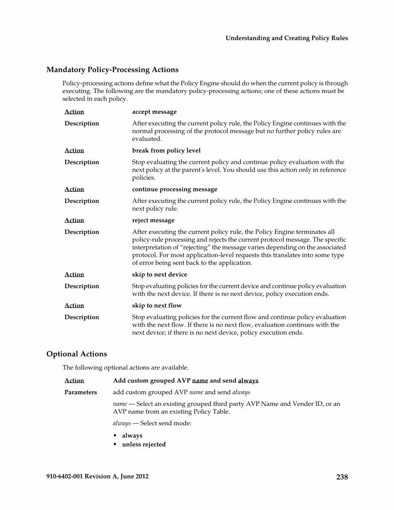
Mandatory Policy-Processing Actions
Policy-processing actions define what the Policy Engine should do when the current policy is throughexecuting. The following are the mandatory policy-processing actions; one of these actions must beselected in each policy.
accept messageAction
After executing the current policy rule, the Policy Engine continues with thenormal processing of the protocol message but no further policy rules areevaluated.
Description
break from policy levelAction
Stop evaluating the current policy and continue policy evaluation with thenext policy at the parent's level. You should use this action only in referencepolicies.
Description
continue processing messageAction
After executing the current policy rule, the Policy Engine continues with thenext policy rule.
Description
reject messageAction
After executing the current policy rule, the Policy Engine terminates allpolicy-rule processing and rejects the current protocol message. The specific
Description
interpretation of “rejecting” the message varies depending on the associatedprotocol. For most application-level requests this translates into some typeof error being sent back to the application.
skip to next deviceAction
Stop evaluating policies for the current device and continue policy evaluationwith the next device. If there is no next device, policy execution ends.
Description
skip to next flowAction
Stop evaluating policies for the current flow and continue policy evaluationwith the next flow. If there is no next flow, evaluation continues with thenext device; if there is no next device, policy execution ends.
Description
Optional Actions
The following optional actions are available.
Add custom grouped AVP name and send alwaysAction
add custom grouped AVP name and send alwaysParameters
name — Select an existing grouped third party AVP Name and Vender ID, or anAVP name from an existing Policy Table.
always — Select send mode:
• always• unless rejected
238910-6402-001 Revision A, June 2012
Understanding and Creating Policy Rules

• if rejected• or send mode from an existing Policy Table
Add or send new custom grouped AVP to the current reply. A condition can be setspecifying that the AVP is always set to send mode. If you are defining a new grouped
Description
third party AVP with members, the grouped AVP has to appear first in the policy.If you are adding a new member AVP that does not have its parent AVP added yet,the policy attempts to locate this grouped AVP in the rest of the policy. If you areincluding a grouped AVP multiple times in the same message, you have to followthe order in which it appears in the message.
Advanced: set values for QoS and Charging parameters to specified valueAction
Advanced: set values for QoS and Charging parameters to profile-paramParameters
profile-param — Names of profile parameters that are derived from internalrepresentations of protocol messages. This list is lengthy and subject to change asnew protocols are supported, and therefore is not given here. The CMP policywizard includes a customized dialog to help you in the selection of valid values.For the specific meaning of the fields it may be necessary to consult protocolspecifications.
Overwrites the corresponding settings in the current protocol message. If you specifysettings that are not relevant in the current protocol message, they are ignored. If
Description
you select Diameter Enforcement Session Event Triggers, you are presented withanother dialog where you can select ECGI_CHANGE and TAI_CHANGE, in additionto the list of previous triggers.
apply specified profile(s) to all flows in the requestAction
apply traffic-profile to all flows in the requestParameters
traffic-profile — One or more traffic profiles. For more information on traffic profiles,see Managing Traffic Profiles.
This parameter allows you to choose different traffic profiles to apply to differenttypes of calls.
Description
apply specified profile(s) to requestAction
apply traffic-profile to requestParameters
traffic-profile — One or more traffic profiles. For more information on traffic profiles,see Managing Traffic Profiles.
Overwrites the corresponding settings in the current protocol message. If multipletraffic profiles are selected they are applied in the order in which they are specified.
Description
If the traffic profile contains settings that are not relevant in the current protocolmessage, then they are simply ignored.
apply specified profile(s) to selected specified type(s) flows in the requestAction
apply traffic-profile to selected specified type(s) flows in the requestParameters
traffic-profile — One or more traffic profiles. For more information on traffic profiles,see Managing Traffic Profiles.
specified type(s) — One or more of the following, used to determine the type of media:
239910-6402-001 Revision A, June 2012
Understanding and Creating Policy Rules

• Audio• Video• Data• Application• Control• Text• Message• Other
Overwrites the corresponding settings in the protocol messages of the specifiedtype. If multiple traffic profiles are selected they are applied in the order in which
Description
they are specified. If the traffic profile contains settings that are not relevant in thecurrent protocol message, then they are simply ignored. The second parameter letsyou choose different traffic profiles to apply to different types of call.
clear alarm with severity ̀ severity level`, id ̀ unique alarm identifier` and message`message text`
Action
clear alarm with severity `level`, id `alarm-id` and message `message`Parameters
level — One of the following, used to determine which alarm ID is cleared:
• Critical (ID 74000)• Major (ID 74001)• Minor (ID 74002)
alarm-id — The alarm ID. If you select Evaluate as expression, the text in the fieldis evaluated as an arithmetic expression, and the result is used.
message — String. This text may contain policy parameters (described later in thissection) to perform parameter substitution within the message text. If you selectEvaluate as expression, the text in the field is evaluated as an arithmetic expression,and the result is used.
Clears an alarm on the CMP Active Alarms display containing the specified severitylevel and message text. This notification is written to the Alarm History Report with
Description
severity Clear. To be cleared, a notification must be uniquely identified by severityand alarm ID. For more information, see Viewing Active Alarms.
disable forwarding to next hop gatewayAction
Disables forwarding to the next hop gateway.Description
disable monitoring keyAction
disable mon-keyParameters
mon-key — Name(s) of a monitoring key.
Disables usage monitoring from the PCEF. This sets the value of theUsage-Monitoring-Information AVP sent to the MPE device to
Description
USAGE_MONITORING_DISABLED. The MPE device will send a usage report.See Managing Monitoring Keys for information on monitoring keys.
disable VLAN taggingAction
240910-6402-001 Revision A, June 2012
Understanding and Creating Policy Rules

Disables VLAN tagging.Description
enable forwarding to next hop gateway with address noneAction
enable forwarding to next hop gateway with address ip-addressParameters
ip-address — Gateway address in IPv4 or IPv6 format.
Forwards to the next hop gateway with the specified IP address.Description
enable subscription for notification of user profile changesAction
The MPE device subscribes to an SPR system for notification of user profile changes.Description
enable subtracting usage from select quota for monitoring keyAction
volume-type subtracting usage from quota-name for mon-keyParameters
volume-type — One of the following:
• enable (the default)• disable
quota-name — Name(s) of quota defined in the CMP.
mon-key — Name(s) of a monitoring key.
Allows or disallows subtraction of the usage reported by the specified monitoringkey(s) from the specified quota(s). See Managing Quotas for information on quotas.See Managing Monitoring Keys for information on monitoring keys.
Description
In this example, to implement a free promotion, quota granted for a video sessionis subtracted from the total used at the session level:
where the request is creating a new session install video PCC rule(s) for session
Example
grant total volume to 100 percent used for video1 using key2 grant total volume to 100 percent used for quota1enable subtracting usage from quota1 for key2
enable VLAN tagging with Id specifiedAction
enable VLAN tagging with Id idParameters
id — VLAN ID
Enables VLAN tagging.Description
establish traffic detection session using the IP-CAN TDF informationAction
None.Parameters
On a IP-CAN session establishment, the policy action will trigger a TSR commandthat is sent to the TDF device. This information is received in the TDF-informationAVP within the IP-CAN session request.
Description
establish traffic detection session with select network element identityAction
establish traffic detection session with tdfParameters
tdf — one or more TDF network elements defined in the CMP database.
241910-6402-001 Revision A, June 2012
Understanding and Creating Policy Rules

On a IP-CAN session establishment, the policy action will trigger a TSR commandthat is sent to the selected TDF device to establish an Sd session.
Description
evaluate policy group select policy groupAction
evaluate policy group group-nameParameters
group-name — Name of a policy group defined in the CMP.
If the conditions evaluates to true, evaluate the rules in a policy group. When youclick on the select policy group parameter, a pop-up window opens so you canselect an existing policy group.
Description
evaluate policy select policyAction
evaluate policy policy-nameParameters
policy-name — Name of a policy defined in the CMP.
If the conditions evaluate to true, evaluate a policy. When you click on the selectpolicy parameter, a pop-up window opens, giving you the choice of selecting an
Description
existing policy or creating a new policy. If you click Create, a new Policy Wizardtab opens so you can create the new policy. When you save the new policy, it isadded to the list of policies available for selection at this point.
grant # bytes for quotaAction
grant number bytes for quotaParameters
number — See common parameters.
Grants a user the specified number of bytes for the requested service. See ManagingQuotas for information on quotas.
Description
grant # percent in service-specific units for quotaAction
grant extended-percent percent in service-specific units for quotaParameters
extended-percent — See common parameters.
Grants a user the specified percentage of the service-specific unit limit for therequested service.
Description
grant # percent in time for quotaAction
grant extended-percent percent in time for quotaParameters
extended-percent — See common parameters.
Grants a user the specified percentage of the initial time limit (in seconds) for therequested service.
Description
grant # percent in volume for quotaAction
grant extended-percent percent in volume for quotaParameters
extended-percent — See common parameters.
Grants a user the specified percentage of their volume limit (in bytes) for therequested service.
Description
grant # percent of select type for select quotaAction
grant number percent of type for quota-nameParameters
242910-6402-001 Revision A, June 2012
Understanding and Creating Policy Rules

number — See common parameters.
type — One of the following:
• Time• Volume• Service Specific
quota-name — Names of quotas defined in the CMP.
Provisions the usage threshold to the specified percentage of time, volume, orservice-specific quantity for the selected quota profile(s). See Managing Quotas forinformation on quotas.
Description
grant 100 percent of remaining on Volume for GoldDailyVol,GoldWeeklyVol,GoldMonthlyVol
Example
grant # percent of select units for select quotaAction
grant number percent of unit for quota-nameParameters
number — See common parameters.
unit — One of the following:
• Seconds• Bytes• Service Specific
quota-name — Names of quotas defined in the CMP.
Provisions the usage threshold to the specified percentage of units for the selectedquota profile(s). See Managing Quotas for information on quotas.
Description
grant 40 percent of Bytes for DailyVol,MonthlyVolExample
grant # seconds for quotaAction
grant number seconds for quotaParameters
number — See common parameters.
Grants a user the specified amount of time (in seconds) for the requested service.See Managing Quotas for information on quotas.
Description
grant # service-specific units for quotaAction
grant number service-specific units for quotaParameters
number — See common parameters.
Grants a user the specified service-specific units for the requested service. SeeManaging Quotas for information on quotas.
Description
grant session time limit to # percent of select quotaAction
grant session time limit to extended-percent percent of quota-nameParameters
extended-percent — See common parameters.
243910-6402-001 Revision A, June 2012
Understanding and Creating Policy Rules

quota-name — Name of quota defined in the CMP database.
Provisions the session time limit based on a percentage of the time limit, retrievedfrom the up to five, for the named quota profile. See Managing Quotas for informationon quotas.
Description
grant total volume to # bytes for select quotaAction
grant volume-type volume to number bytes for quota-nameParameters
volume-type — One of the following:
• total (the default)• uplink• downlink
number — See common parameters.
quota-name — Name of quota defined in the CMP database.
Provisions the session volume limit in bytes for the named quota profile. SeeManaging Quotas for information on quotas.
Description
grant total volume to # bytes of select quota using monitoring keyAction
grant volume-type volume to number bytes of quota-type using mon-keyParameters
volume-type — One of the following:
• total (the default)• uplink• downlink
number — See common parameters.
quota-type — One of the following:
• used (the default) — Calculates the quota to grant by subtracting the specifiedamount in bytes from the initial quota limit minus the quota used so far.
• initial — Calculates the quota to grant by subtracting the specified amount inbytes from the initial quota limit.
mon-key — Name(s) of a monitoring key.
Allows quota profiles to be associated with one or more monitoring keys. This actioncan be used at the session and rule levels. If two policy actions grant usage for the
Description
same monitoring key or usage instance, the last action takes precedence, unless anaction grants uplink volume followed by an action that grants downlink volume(or vice versa), which case the actions are grouped as one action when the messageis processed. A policy that grants quota for a monitoring key will overwrite anyprevious grant of quota for that same monitoring key. This includes any subtractionpreviously enabled for the same monitoring key. See Managing Quotas for informationon quotas. See Managing Monitoring Keys for information on monitoring keys.
grant total volume to # percent used for select quotaAction
grant volume-type volume to extended-percent percent quota-type for quota-nameParameters
244910-6402-001 Revision A, June 2012
Understanding and Creating Policy Rules

volume-type — One of the following:
• total (the default)• uplink• downlink
extended-percent — See common parameters.
quota-type — One of the following:
• used (the default) — Calculates the quota to grant by multiplying the percentagetimes the initial quota limit minus the quota used so far.
• initial — Calculates the quota to grant by multiplying the percentage times theinitial quota limit.
quota-name — Name(s) of quota defined in the CMP.
Provisions the session volume limit based on a percentage of the volume used,retrieved from the SPR, for the named quota profile. This action can only be usedat the session level. See Managing Quotas for information on quotas.
Description
grant total volume to # percent used for select quota using monitoring keyAction
grant volume-type volume to extended-percent percent quota-type for quota-name usingmon-key
Parameters
volume-type — One of the following:
• total (the default)• uplink• downlink
extended-percent — See common parameters.
quota-type — One of the following:
• used (the default) — Calculates the quota to grant by multiplying the percentagetimes the the initial quota limit minus the quota used so far.
• initial — Calculates the quota to grant by multiplying the percentage times thethe initial quota limit.
quota-name — Name(s) of quota defined in the CMP.
mon-key — Name(s) of a monitoring key.
Allows quota profiles to be associated with one or more monitoring keys. This actioncan be used at the session and rule levels. If two policy actions grant usage for the
Description
same monitoring key or usage instance, the last action takes precedence, unless anaction grants uplink volume followed by an action that grants downlink volume(or vice versa), which case the actions are grouped as one action when the messageis processed. A policy that grants quota for a monitoring key will overwrite anyprevious grant of quota for that same monitoring key. This includes any subtractionpreviously enabled for the same monitoring key. See Managing Quotas for informationon quotas. See Managing Monitoring Keys for information on monitoring keys.
245910-6402-001 Revision A, June 2012
Understanding and Creating Policy Rules

where the request is creating a new session grant total volume to 100 percent used for Monthly1,Daily1 using
Example
key1
continue processing message
install specified PCC rule(s) for select scopeAction
install pcc-rule PCC rule(s) for pcc-rule-scope-installParameters
pcc-rule — Names of policy and charging control profiles that are defined in theCMP. The traffic profiles must be one of the following types:
• PCC Rule• Predefined PCC Rule• Predefined PCC Rule Base
pcc-rule-scope-install — One of the following:
• flow• session
The specified PCC rule is installed for either the session or flow, using the valuesspecified in the associated traffic profile.
Description
install specified PCC rule(s) for select scope active between start time and endtime
Action
install pcc-rule PCC rule(s) for pcc-rule-scope-install active between start-time andend-time
Parameters
pcc-rule — Names of policy and charging control profiles that are defined in theCMP. The traffic profiles must be one of the following types:
• PCC Rule• Predefined PCC Rule• Predefined PCC Rule Base
pcc-rule-scope-install — One of the following:
• flow• session
start-time and end-time — Specifies the start and end time for rule to be active. Ifstart time is not specified, the rule becomes active immediately. If end time is notspecified, the rule never deactivates. Select either absolute time or relative time forboth start-time and end-time:
• Absolute time but no date — Specifies the time to start/end in the formHH:mm:ss. The date is calculated to be the minimum future date for that time.
• Absolute time and date — Specifies the time and date to start/end in the formYYYY-MM-ddTHH:mm:ss.
• Relative time — Specifies the number of hours, minutes, or seconds from thecurrent time to start/end. Variables include:
246910-6402-001 Revision A, June 2012
Understanding and Creating Policy Rules

• Date• Time• UTC Offset — select number of hours before or after UTC time to start/end.• Now — check mark to start/end now.• Time only — check mark to ignore date selected.
The specified PCC rule is installed for either the session or flow, using the valuesspecified in the associated traffic profile, and is active between the specified startand end times.
Description
install specified PCC rule(s) for select scope active within Time PeriodAction
install pcc-rule PCC rule(s) for pcc-rule-scope-install active within time-periodParameters
pcc-rule — Names of policy and charging control profiles that are defined in theCMP. The traffic profiles must be one of the following types:
• PCC Rule• Predefined PCC Rule• Predefined PCC Rule Base
pcc-rule-scope-install — One of the following:
• flow• session
time-period — Specifies the time period when the rule is active. When that timeperiod begins the rule activates, and when the time period ends the rule deactivates.Select one of the following:
• Time Period — Select pre-defined time period• Policy Table Field — Select time-related field from Policy Table selected for this
Policy.
The specified PCC rule is installed for either the session or flow, using the valuesspecified in the associated traffic profile, and the rule is active for the specified time
Description
period. Note that when a Time Period is used in a policy, the user cannot deletethat time period.
install specified PCC rule(s) for select scope for specified retry profile activewithin Time Period
Action
install pcc-rule PCC rule(s) for pcc-rule-scope-install with retryprofile active withintime-period
Parameters
pcc-rule — Names of policy and charging control profiles that are defined in theCMP. The traffic profiles must be one of the following types:
• PCC Rule• Predefined PCC Rule• Predefined PCC Rule Base
pcc-rule-scope-install — One of the following:
247910-6402-001 Revision A, June 2012
Understanding and Creating Policy Rules

• flow• session
retryprofile — Name of a retry profile that is defined in the CMP. (See ManagingRetry Profiles for more information.)
time-period — Specifies the time period when the rule is active. When that timeperiod begins the rule activates, and when the time period ends the rule deactivates.Select one of the following:
• Time Period — Select pre-defined time period• Policy Table Field — Select time-related field from Policy Table selected for this
Policy.
The specified PCC rule is installed for either the session or flow, using the valuesspecified in the associated traffic profile and the associated retry profile, and therule is active for the specified time period.
Description
install specified PCC rule(s) for select scope for specified retry profile activebetween start time and end time
Action
install pcc-rule PCC rule(s) for pcc-rule-scope-install with retryprofile active betweenstart-end-time
Parameters
pcc-rule — Names of policy and charging control profiles that are defined in theCMP. The traffic profiles must be one of the following types:
• PCC Rule• Predefined PCC Rule• Predefined PCC Rule Base
pcc-rule-scope-install — One of the following:
• flow• session
retryprofile — Name of a retry profile that is defined in the CMP. (See ManagingRetry Profiles for more information.)
start-end-time — Specifies the start and end time for rule to be active. If start time isnot specified, the rule becomes active immediately. If end time is not specified, therule never deactivates. Select either absolute time or relative time for both start-timeand end-time:
• Absolute time but no date — Specify the time to start/end in the formHH:mm:ss. The date is calculated to be the minimum future date for that time.
• Absolute time and date — Specify the time and date to start/end in the formYYYY-MM-ddTHH:mm:ss.
• Relative time — Specify the number of hours, minutes, or seconds from thecurrent time to start/end. Variables include:
• Date• Time• UTC Offset — select number of hours before or after UTC time to start/end.
248910-6402-001 Revision A, June 2012
Understanding and Creating Policy Rules

• Now — check mark to start/end now.• Time only — check mark to ignore date selected.
The specified PCC rule is installed for either the session or flow, using the valuesspecified in the associated traffic profile and the associated retry profile, and isactive between the specified start and end times.
Description
install specified PCC rule(s) for select scope with specified retry profileAction
install pcc-rule PCC rule(s) for pcc-rule-scope-install with retryprofileParameters
pcc-rule — Names of policy and charging control profiles that are defined in theCMP. The traffic profiles must be one of the following types:
• PCC Rule• Predefined PCC Rule• Predefined PCC Rule Base
pcc-rule-scope-install — One of the following:
• flow• session
retryprofile — Name of a retry profile that is defined in the CMP. (See ManagingRetry Profiles for more information.)
The specified PCC rule is installed for either the session or flow, using the valuesspecified in the associated traffic profile and the associated retry profile.
Description
mark request AVP name as failed if exists and send alwaysAction
mark request AVP name as failed if exists and send alwaysParameters
name — String representing existing AVP name, entered in this format -- AVPName:VendorID, or for nested AVP names in an AVP group, entered in this format-- AVP Name 1:VendorID.AVP Name 2:VendorID. An AVP name can also be selectedfrom an existing Policy Table. There is also the option to evaluate as an expression(click to select check box).
always — Send mode:
• always (the default)• unless rejected• if rejected• or send mode from an existing Policy Table
Marks a request AVP as failed in the reply message, and notifies the opposite peerof the failed AVP validation. This action supports both loaded base Diameter AVPsand third-party AVPs.
Description
re-authorize all credit control sessions associated with UserAction
Triggers reauthorization for PCEF sessions for all the user's sessions.Description
re-authorize all PCEF sessions associated with select scopeAction
249910-6402-001 Revision A, June 2012
Understanding and Creating Policy Rules

re-authorize all PCEF sessions associated with pcef-scope-installParameters
pcef-scope-install— One of the following:
• IP-CAN session• user
Triggers reauthorization for PCEF sessions, either within the IP-CAN sessionassociations (that is, all Gx sessions sharing the same IP address and APN) or for
Description
all the user's sessions (that is, all Gx sessions sharing the same user ID). Eachreauthorization request contains the original event that triggered the reauthorizationaction, so information from this event can be evaluated by the policy engine duringthe evaluation of the request. For example, an event trigger received in a CCR onone interface, such as RAT_CHANGE, can be used in the evaluation of thereauthorization request triggered by this CCR. This action is valid regardless ofwhether Gx correlation is enabled or disabled.
release all credit control sessions associated with UserAction
Triggers release of credit control sessions for all the user's sessions.Description
release all PCEF sessions associated with select scopeAction
release all PCEF sessions associated with pcef-scope-installParameters
pcef-scope-install— One of the following:
• IP-CAN session• user
Triggers release of PCEF sessions, either within the IP-CAN session associations(that is, all Gx sessions sharing the same IP address and APN) or for all the user'ssessions (that is, all Gx sessions sharing the same user ID).
Description
release the sessionAction
Releases the session.Description
remove all policy context propertiesAction
Removes all subscriber properties in the SPR.Description
remove all the subscriber or pool properties and save alwaysAction
remove all the subscriber properties and save save-modeParameters
subscriber — One of the following:
• subscriber (the default) — Individual subscriber• pool — Name of a quota pool defined in the CMP database
save-mode — One of the following:
• always (the default)• unless rejected
Deletes all the properties for a subscriber or pool quota from the SPR. You canspecify that the properties are not deleted if the policy rejects the message.
Description
250910-6402-001 Revision A, June 2012
Understanding and Creating Policy Rules

remove custom AVP name from reply alwaysAction
remove custom AVP name from reply alwaysParameters
name — An existing AVP Name and Vender ID, or an AVP name from an existingPolicy Table.
always — Send mode:
• always (the default)• unless rejected• if rejected• or send mode from an existing Policy Table
Removes the custom AVP name previously set from the reply message.Description
remove PCC rule type(s) select type(s) of rules for select scopeAction
remove PCC rule type(s) pcc-rule-type for pcc-rule-scope-installParameters
pcc-rule-type — One or more of the following:
• none• predefined• predefined base• dynamically provisioned• all
pcc-rule-scope-install — One of the following:
• flow• session• all
Removes the policy and charging control rules from the current flow/session basedon their type.
Description
remove policy context property nameAction
remove policy context property property-nameParameters
property-name — String. May contain policy rule variables (see Policy Rule Variables)to perform parameter substitution within the property name.
Removes a subscriber property in the SPR.Description
remove specified PCC rule(s)Action
remove pcc-rule PCC rule(s)Parameters
pcc-rule — Names of policy and charging control profiles that are defined in theCMP. The traffic profiles must be one of the following types:
• PCC Rule• Predefined PCC Rule• Predefined PCC Rule Base
251910-6402-001 Revision A, June 2012
Understanding and Creating Policy Rules

Removes the PCC rules from the current flow/session.Description
remove the subscriber or pool property name and save alwaysAction
remove the subscriber property property-name and save save-modeParameters
subscriber — One of the following:
• subscriber (the default) — Individual subscriber• pool — Name of a quota pool defined in the CMP database
property-name — String.
save-mode — One of the following:
• always (the default)• unless rejected
Deletes a subscriber or quota pool property from the SPR. You can specify that theproperty is not deleted if the policy rejects the message.
Description
remove the FamilyPlanGold property stc-approved and save unless rejected
Example
request usage report for monitoring keyAction
request usage report for mon-keyParameters
mon-key — Name of a monitoring key.
Requests a usage report from the PCEF. This sets the value of theUsage-Monitoring-Information AVP sent to the MPE device to
Description
USAGE_MONITORING_REPORT_REQUIRED. See Managing Monitoring Keys forinformation on monitoring keys.
reset all quota usageAction
Resets all quotas for the subscriber.Description
reset usage for select quotaAction
reset usage for quota-nameParameters
quota-name — Name of quota defined in the CMP.
Resets the selected quota. See Managing Quotas for information on quotas.Description
revalidate the session at datetime using configured local timeAction
revalidate the session at datetime using time-zoneParameters
datetime — A policy rule variable or a timestamp in the formatyyyy-mm-ddThh:mm:ss+UTCoffset. If you select Evaluate as expression, the text inthe field is evaluated as an arithmetic expression, and the result is used.
time-zone — One of the following:
• configured local time (the default) — Calculate the time from the locationconfigured for this MPE device
• system local time — Calculate the time from the location of this MPE device
252910-6402-001 Revision A, June 2012
Understanding and Creating Policy Rules

• user local time — Calculate the time from the location of the user equipment
Revalidates the session at the specified time. If time-zone information is availablefrom the user equipment, time can be calculated from either the MPE device or theuser equipment's location.
Description
revalidate the session at {User.State.end-time} using configured local time
Example
send notification to syslog with `message text` and severity `severity level`Action
send notification to syslog with `message` and severity `level`Parameters
message — String. This text may contain policy parameters (described later in thissection) to perform parameter substitution within the message text. If you selectEvaluate as expression, the text in the field is evaluated as an arithmetic expression,and the result is used.
level — The sevlog severity. One of the following:
• Emergency• Alert• Critical• Error• Warning• Notice• Info• Debug
Writes a message to the syslog file containing the specified message text and severitylevel.
Note: Policies written before V7.5 that used the action send alert with `text` andseverity ̀ severity level` will be converted to use this action instead, which will senda notification to syslog instead of an alarm to the CMP.
Description
send notification to trace log with `message text` and severity `severity level`Action
send notification to trace log with `message` and severity `level`Parameters
message — String. This text may contain policy parameters (described later in thissection) to perform parameter substitution within the message text. If you selectEvaluate as expression, the text in the field is evaluated as an arithmetic expression,and the result is used.
level — One of the following:
• Emergency (ID 4560)• Alert (ID 4561)• Critical (ID 4562)• Error (ID 4563)• Warning (ID 4564)• Notice (ID 4565)• Info (ID 4566)
253910-6402-001 Revision A, June 2012
Understanding and Creating Policy Rules

• Debug (ID 4567)
Sends a message to the trace log containing the specified message text and at thespecified severity level. If the configured minimum notification severity level is
Description
higher than that specified in the policy action, then the policy action does notgenerate the notification.
Note: Policies written before V7.5 that used the action write `text` to the log filewill be converted to use this action instead, with the severity Info.
send SMS ̀ specified` to ̀ default` destination address, ̀ default` TON and ̀ default`NPI from `default` source address, `default` TON and `default` NPI. Requestdelivery receipt `default`.
Action
send SMS `message` to `dest_address` destination address, `ton` TON and `npi` NPIfrom `source_address` source address, `ton` TON and `npi` NPI. Request deliveryreceipt `receipt`.
Parameters
message — String. This text may contain policy parameters (described later in thissection) to perform parameter substitution within the message text.
dest_address — String. If not the default, this overrides the configured address. Youcan specify dest_address as one or more comma-separated static values, or as one ormore comma-separated references to custom fields in the subscriber profile. Amaximum of five comma-separated values can be entered.
ton — If not the default, this overrides the configured Type of Number. One of thefollowing:
• default• UNKNOWN• INTERNATIONAL• NATIONAL• NETWORK SPECIFIC• SUBSCRIBER NUMBER• ALPHANUMERIC• ABBREVIATED
npi — If not the default, this overrides the configured Number Plan Indicator. Oneof the following:
• default• UNKNOWN• ISDN (E163/E164)• DATA (X.121)• TELEX (F.69)• LAND MOBILE (E.212)• NATIONAL• PRIVATE• ERMES• INTERNET (IP)• WAP CLIENT ID
254910-6402-001 Revision A, June 2012
Understanding and Creating Policy Rules

source_address — String. If not the default, this overrides the configured address.
receipt — One of the following:
• default — Use global default configured for this MPE device.• No Delivery Receipt (the default)• Delivery Receipt on success and failure• Delivery Receipt on failure
Sends an SMS text message, with the specified text, to the subscriber associatedwith the message. In SMPP mode, messages can be up to 254 characters long. The
Description
default source and destination address, TON, and NPI configured on the MPEdevice can be used or overridden.
To send notifications to multiple destinations, you can specify dest_address as oneor more comma-separated static values, or as one or more comma-separatedreferences to custom fields in the subscriber profile. Destinations must all be of thesame type; this ensures that the same TON and NPI settings configured in the policyaction will apply to all destinations. No transformations are performed on thesubscriber’s profile data by the MPE device, so custom fields used as alternatedestinations must contain values formatted as required by the SMSC. Multivaluedfields (LDAP attributes) are not supported.
If the address(es) specified are not available (for example, if a custom field is notpopulated in the subscriber database), then the global default is used; if the globaldefault is not configured, then the SMS message is sent to the subscriber's MSISDN;if the subscriber's MSISDN cannot be determined, then no SMS message is sent anda trace log alert is generated.
You can request a receipt from the SMSC server, which will be logged in the fileSMPP.log, when the message is delivered to the subscriber. You can request a receipton success, failure, or either. See Configuring Protocol Options on the Policy Server forinformation on configuring delivery receipt default behavior.
send SMS `you have reached 80%% of your quota` to `{User.MSISDN},{User.AltDest1},{User.AltDest2}` destination address,
Example
`default` TON and `default` NPI from `614` source address, `default` TON and `default` NPI. Request delivery receipt `Default`.
send SMS ̀ specified` to ̀ default` destination address, ̀ default` TON and ̀ default`NPI from ̀ default` source address, ̀ default` TON and ̀ default` NPI on user billingday. Request delivery receipt `default`.
Action
send SMS `message` to `dest_address` destination address, `ton` TON and `npi` NPIfrom `source_address` source address, `ton` TON and `npi` NPI on user billing day.Request delivery receipt `receipt`.
Parameters
message — String. This text may contain policy parameters (described later in thissection) to perform parameter substitution within the message text.
dest_address — String. If not the default, this overrides the configured address. Youcan specify dest_address as one or more comma-separated static values, or as one ormore comma-separated references to custom fields in the subscriber profile.
ton — If not the default, this overrides the configured Type of Number. One of thefollowing:
255910-6402-001 Revision A, June 2012
Understanding and Creating Policy Rules

• default• UNKNOWN• INTERNATIONAL• NATIONAL• NETWORK SPECIFIC• SUBSCRIBER NUMBER• ALPHANUMERIC• ABBREVIATED
npi — If not the default, this overrides the configured Number Plan Indicator. Oneof the following:
• default• UNKNOWN• ISDN (E163/E164)• DATA (X.121)• TELEX (F.69)• LAND MOBILE (E.212)• NATIONAL• PRIVATE• ERMES• INTERNET (IP)• WAP CLIENT ID
source_address — String. If not the default, this overrides the configured address.
receipt — One of the following:
• default — Use global default configured for this MPE device.• No Delivery Receipt (the default)• Delivery Receipt on success and failure• Delivery Receipt on failure
Sends an SMS text message, with specified text, to the subscriber associated withthe message on the subscribers billing day. In SMPP mode, messages can be up to
Description
254 characters long. The default source and destination address, TON, and NPIconfigured on the MPE device can be used or overridden.
To send notifications to multiple destinations, you can specify dest_address as oneor more comma-separated static values, or as one or more comma-separatedreferences to custom fields in the subscriber profile. Destinations must all be of thesame type; this ensures that the same TON and NPI settings configured in the policyaction will apply to all destinations. No transformations are performed on thesubscriber’s profile data by the MPE device, so custom fields used as alternatedestinations must contain values formatted as required by the SMSC. Multivaluedfields (LDAP attributes) are not supported.
If the address(es) specified are not available (for example, if a custom field is notpopulated in the subscriber database), then the global default is used; if the globaldefault is not configured, then the SMS message is sent to the subscriber's MSISDN;
256910-6402-001 Revision A, June 2012
Understanding and Creating Policy Rules

if the subscriber's MSISDN cannot be determined, then no SMS message is sent anda trace log alert is generated.
You can request a receipt from the SMSC server, which will be logged in the fileSMPP.log, when the message is delivered to the subscriber. You can request a receipton success, failure, or either. See Configuring Protocol Options on the Policy Server forinformation on configuring delivery receipt default behavior.
send SMS `you have reached 80%% of your quota` to `{User.MSISDN},{User.AltDest1},{User.AltDest2}` destination address,
Example
`default` TON and `default` NPI from `614` source address, `default` TON and `default` NPI on user billing day. Request delivery receipt `Default`.
send SMS `specified` to `default` destination address from `default` sourceaddress. Request delivery receipt `default`.
Action
send SMS ̀ message` to ̀ dest_address` destination address from ̀ source_address` sourceaddress. Request delivery receipt `receipt`.
Parameters
message — String. This text may contain policy parameters (described later in thissection) to perform parameter substitution within the message text.
dest_address — String. If not the default, this overrides the configured address. Youcan specify dest_address as one or more comma-separated static values, or as one ormore comma-separated references to custom fields in the subscriber profile.
source_address — String. If not the default, this overrides the configured address.
receipt — One of the following:
• default — Use global default configured for this MPE device.• No Delivery Receipt (the default)• Delivery Receipt on success and failure• Delivery Receipt on failure
Sends an SMS text message, with the specified text, to the subscriber associatedwith the message. In SMPP mode, messages can be up to 254 characters long. Thedefault source and destination address can be used or overridden.
Description
To send notifications to multiple destinations, you can specify dest_address as oneor more comma-separated static values, or as one or more comma-separatedreferences to custom fields in the subscriber profile. Destinations must all be of thesame type; this ensures that the same TON and NPI settings configured in the policyaction will apply to all destinations. No transformations are performed on thesubscriber’s profile data by the MPE device, so custom fields used as alternatedestinations must contain values formatted as required by the SMSC. Multivaluedfields (LDAP attributes) are not supported.
If the address(es) specified are not available (for example, if a custom field is notpopulated in the subscriber database), then the global default is used; if the globaldefault is not configured, then the SMS message is sent to the subscriber's MSISDN;if the subscriber's MSISDN cannot be determined, then no SMS message is sent anda trace log alert is generated.
257910-6402-001 Revision A, June 2012
Understanding and Creating Policy Rules

You can request a receipt from the SMSC server, which will be logged in the fileSMPP.log, when the message is delivered to the subscriber. You can request a receipton success, failure, or either. See Configuring Protocol Options on the Policy Server forinformation on configuring delivery receipt default behavior.
send SMS `you have reached 80%% of your quota` to `{User.MSISDN},{User.AltDest1},{User.AltDest2}`
Example
destination address from `614` source address. Request delivery receipt `Default`.
send SMS ̀ specified` to ̀ default` destination address from ̀ default` source addresson user billing day. Request delivery receipt `default`.
Action
send SMS ̀ message` to ̀ dest_address` destination address from ̀ source_address` sourceaddress on user billing day. Request delivery receipt `receipt`.
Parameters
message — String. This text may contain policy parameters (described later in thissection) to perform parameter substitution within the message text.
dest_address — String. If not the default, this overrides the configured address. Youcan specify dest_address as one or more comma-separated static values, or as one ormore comma-separated references to custom fields in the subscriber profile.
source_address — String. If not the default, this overrides the configured address.
receipt — One of the following:
• default — Use global default configured for this MPE device.• No Delivery Receipt (the default)• Delivery Receipt on success and failure• Delivery Receipt on failure
Sends an SMS text message, with specified text, to the subscriber associated withthe message on the subscriber's billing day. In SMPP mode, messages can be up to
Description
254 characters long. The default source and destination address can be used oroverridden.
To send notifications to multiple destinations, you can specify dest_address as oneor more comma-separated static values, or as one or more comma-separatedreferences to custom fields in the subscriber profile. Destinations must all be of thesame type; this ensures that the same TON and NPI settings configured in the policyaction will apply to all destinations. No transformations are performed on thesubscriber’s profile data by the MPE device, so custom fields used as alternatedestinations must contain values formatted as required by the SMSC. Multivaluedfields (LDAP attributes) are not supported.
If the address(es) specified are not available (for example, if a custom field is notpopulated in the subscriber database), then the global default is used; if the globaldefault is not configured, then the SMS message is sent to the subscriber's MSISDN;if the subscriber's MSISDN cannot be determined, then no SMS message is sent anda trace log alert is generated.
You can request a receipt from the SMSC server, which will be logged in the fileSMPP.log, when the message is delivered to the subscriber. You can request a receipton success, failure, or either. See Configuring Protocol Options on the Policy Server forinformation on configuring delivery receipt default behavior.
258910-6402-001 Revision A, June 2012
Understanding and Creating Policy Rules

send SMS `you have reached 80%% of your quota` to `{User.MSISDN},{User.AltDest1},{User.AltDest2}` destination address
Example
from `614` source address on user billing day. Request delivery receipt `Default`.
send SMS `specified` to user. Request delivery receipt `default`.Action
send SMS `message` to user. Request delivery receipt `receipt`.Parameters
message — String. This text may contain policy parameters (described later in thissection) to perform parameter substitution within the message text. If you selectEvaluate as expression, the text in the field is evaluated as an arithmetic expression,and the result is used.
receipt — One of the following:
• default — Use global default configured for this MPE device.• No Delivery Receipt (the default)• Delivery Receipt on success and failure• Delivery Receipt on failure
Sends an SMS text message, with specified text, to the subscriber associated withthe message. In SMPP mode, messages can be up to 254 characters long.
Description
You can request a receipt from the SMSC server, which will be logged in the fileSMPP.log, when the message is delivered to the subscriber. You can request a receipton success, failure, or either. See Configuring Protocol Options on the Policy Server forinformation on configuring delivery receipt default behavior.
send SMS `you have reached 80%% of your quota` to user. Request delivery receipt `Default`.
Example
send SMS `specified` to user on their Billing Day. Request delivery receipt`default`.
Action
send SMS `message` to user on their Billing Day. Request delivery receipt `receipt`.Parameters
message — String. This text may contain policy parameters (described later in thissection) to perform parameter substitution within the message text. If you selectEvaluate as expression, the text in the field is evaluated as an arithmetic expression,and the result is used.
receipt — One of the following:
• default — Use global default configured for this MPE device.• No Delivery Receipt (the default)• Delivery Receipt on success and failure• Delivery Receipt on failure
Sends an SMS text message, with specified text, to the subscriber associated withthe message on the subscriber’s billing day. In SMPP mode, messages can be up to254 characters long.
Description
You can request a receipt from the SMSC server, which will be logged in the fileSMPP.log, when the message is delivered to the subscriber. You can request a receipt
259910-6402-001 Revision A, June 2012
Understanding and Creating Policy Rules

on success, failure, or either. See Configuring Protocol Options on the Policy Server forinformation on configuring delivery receipt default behavior.
send SMTP message with the following text/plain content:Action
To: to_address CC: default BCC: default
From: default Reply-To: default
Subject: subject
Text: message content
Signature: default
send SMTP message with the following format content:Parameters
To: to_address CC: cc_address BCC: bcc_address
From: from_address Reply-To: reply_address
Subject: subject
Text: message
Signature: signature
format — One of the following:
• text/plain (the default) — The email is in plain-text format.• text/html — The email includes HTML formatting.
to_address — String. If not the default, this overrides the configured address. Youcan specify up to five comma-separated static values, or up to five comma-separatedreferences to custom fields in the subscriber profile.
cc_address — String. If not the default, this overrides the configured address. Youcan specify up to five comma-separated static values, or up to five comma-separatedreferences to custom fields in the subscriber profile.
bcc_address — String. If not the default, this overrides the configured address. Youcan specify up to five comma-separated static values, or up to five comma-separatedreferences to custom fields in the subscriber profile.
from_address— String. The address of the author who sent the mail.
Note: You may not necessarily want the reply to come back from this address. Thiscan be configured globally to a default value.
reply_address — String. If not the default, this overrides the configured address.
subject — String.
message — String. Body of the message.
signature — String. If not the default, this overrides the configured signature block.
Sends an email message, with the specified text and signature block, to the subscriberassociated with the address. The message is sent through an SMS Relay (SMSR)interface.
Description
260910-6402-001 Revision A, June 2012
Understanding and Creating Policy Rules

To send email to multiple destinations, you can specify up to five addresses (anycombination of to_address, cc_address, or bc_address) as comma-separated static values,or as comma-separated references to custom fields in the subscriber profile. Youcan specify up to five addresses. Destinations must all be of the same type. Notransformations are performed on the subscriber’s profile data by the MPE device,so custom fields used as alternate destinations must contain values formatted asrequired by the SMSR. Multivalued fields (LDAP attributes) are not supported.
If the address(es) specified are not available (for example, if a custom field is notpopulated in the subscriber database), then the global default is used; if the globaldefault is not configured, then no SMTP message is sent and an SMTP log alert isgenerated. See Configuring Protocol Options on the Policy Server for information onconfiguring SMTP default values.
set alarm with severity `severity level`, id `unique alarm identifier` and message`message text`
Action
set alarm with severity `level`, id alarm-id` and message `message`Parameters
level — One of the following:
• Critical (ID 74000)• Major (ID 74001)• Minor (ID 74002)
alarm-id — The alarm ID. If you select Evaluate as expression, the text in the fieldis evaluated as an arithmetic expression, and the result is used.
message — String. This text may contain policy parameters (described later in thissection) to perform parameter substitution within the message text. If you selectEvaluate as expression, the text in the field is evaluated as an arithmetic expression,and the result is used.
Sends an alarm to the CMP containing the specified severity level and message text.This alarm is written to the Alarm History Report, and will appear in the Active
Description
Alarms display for one hour, until cleared, or unless the server fails over, whichevercomes first. Alarms generated by policy actions do not affect the HA score of aserver, and will not cause a failover. For more information, see Viewing Active Alarms.
set authorization validity time to # secondsAction
set authorization validity time to seconds secondsParameters
seconds — See common parameters.
Sets the authorization expiration time (in seconds) after which the enforcementdevice requests re-authorization from the MPE device for the requested user'sservice.
Description
set authorization validity time to datetimeAction
set authorization validity time to datetimeParameters
datetime — Either the local date-time now (the default) or a timestamp in the formatyyyy-mm-ddThh:mm:ss+UTCoffset.
261910-6402-001 Revision A, June 2012
Understanding and Creating Policy Rules

Sets the authorization expiration time (to the quarter hour) after which theenforcement device requests re-authorization from the MPE device for the requesteduser's service.
Description
set authorization validity time to time on day using configured local timeAction
set authorization validity time to time on day-of-week using time-zoneParameters
time — A time, in the format hh:mm (limited to 15-minute intervals).
day-of-week — One or more of the following:
• Sunday• Monday• Tuesday• Wednesday• Thursday• Friday• Saturday
time-zone — One of the following:
• CONFIGURED LOCAL TIME (the default) — Calculate the time from thelocation configured for this MPE device
• SYSTEM LOCAL TIME — Calculate the time from the location of this MPEdevice
• USER LOCAL TIME — Calculate the time from the location of the userequipment
Sets the authorization expiration time (to the quarter hour) after which theenforcement device requests re-authorization from the MPE device for the requested
Description
user's service. If time-zone information is available from the user equipment, timecan be calculated from either the MPE device or the user equipment's location.
set charging server(s) for the IP-CAN session to specified valuesAction
set charging server(s) for the IP-CAN session to charging-server-nameParameters
charging-server-name — Names of charging servers that are defined in the CMP.
Sets the charging servers, as specified. To define a charging server, see ManagingCharging Servers.
Description
set custom AVP name value to the policy context property nameAction
set custom AVP avp-name value to the policy context property property-nameParameters
avp-name — An existing AVP Name and Vender ID, or an AVP name from anexisting Policy Table.
property-name — String that represent the policy context property.
Makes the AVP value accessible throughout the policy context so other policies canaccess this AVP value as a context property. Note that the context property variablewill be set only if this AVP exists in the request and its value is not null.
Description
set custom AVP name value to the user property name and save alwaysAction
262910-6402-001 Revision A, June 2012
Understanding and Creating Policy Rules

set custom AVP avp-name value to the user property property-name and save alwaysParameters
avp-name — An existing AVP Name and Vender ID, or an AVP name from anexisting Policy Table.
property-name — String that represent the user property; maximum of 255 characterscan be entered.
always — Select send mode:
• always• unless rejected• send mode from an existing Policy Table
Sets an AVP value as a User object property to persist between sessions.Description
set external field to # percent of select type for selected quotaAction
set field to value percent of type for quota-name quotaParameters
field — String name of field in external database.
value — String value of field in external database.
type — One of the following:
• service-specific• time• total volume
quota-name — Name(s) of quotas defined in the CMP.
Sets a field in an external database to a percentage of the time, total volume, orservice-specific quota of one or more selected quotas. This can be an LDAP server
Description
or an SPR. The MPE device on which this policy is executed must have write accessto the database, and the external field must be defined on the MPE device. For moreinformation, see Configuring Data Source Interfaces. See Managing Quotas forinformation on quotas.
set external field to `value`Action
set field to `value`Parameters
field — String name of field in external database.
value — String value of field in external database. If you select Evaluate asexpression, the text in the field is evaluated as an arithmetic expression, and theresult is used.
Sets the value of a field in an external database. This can be an LDAP server or anSPR. The MPE device on which this policy is executed must have write access to
Description
the database, and the external field must be defined on the MPE device. For moreinformation, see Configuring Data Source Interfaces.
263910-6402-001 Revision A, June 2012
Understanding and Creating Policy Rules

set Quota Volume to `{User.Quota.Gold.volume}`
set Last Session to `{Date(yyyy-MM-DD hh:mm:ss:SSSZ)}`
Example
set policy context property name to valueAction
set policy context property property-name to valueParameters
property-name — String. May contain policy rule variables (see Policy Rule Variables)to perform parameter substitution within the property name.
value — String.
Sets and saves a subscriber property in the SPR. You can specify that the propertyis not saved if the policy rejects the message.
Description
set Quota Exhaustion Action to specifiedAction
set Quota Exhaustion Action to actionParameters
action — Specifies the action the GGSN takes when a subscriber reaches the quotagrant. Selecting this parameter opens a window with the following options:
• Quota Exhaustion Action — Select one of the following:
• TERMINATE (the default) — Terminate the subscriber’s session. If you selectthis option, the other options are not applicable.
• REDIRECT — Redirect the session to another server. If you select this option,configure the following additional fields:
• Redirect Server Type — Select IPV4, IPV6, URL, or SIP URI• Redirect Server Address — Type the server address
• RESTRICT ACCESS — If you select this option, additional configurationfields appear:
264910-6402-001 Revision A, June 2012
Understanding and Creating Policy Rules

• Restriction Filters — Type a comma-separated list of Diameter IP Filterrules
• Filter ID List — Type a comma-separated list of named filters on theGGSN
When you finish, click OK (or Cancel to discard your changes).
Sets the action to take if the subscriber’s quota is exhausted. See Managing Quotasfor information on quotas.
Description
set session revalidation time to # secondsAction
set session revalidation time to seconds secondsParameters
seconds — See common parameters.
Provisions the session revalidation time to the number of seconds from when thepolicy executes.
Description
set session revalidation time to time on day using configured local timeAction
set session revalidation time to time on day-of-week using time-zoneParameters
time — A time, in the format hh:mm (limited to 15-minute intervals).
day-of-week — One or more of the following:
• Sunday• Monday• Tuesday• Wednesday• Thursday• Friday• Saturday
time-zone — One of the following:
• configured local time (the default) — Calculate the time from the locationconfigured for this MPE device
• system local time — Calculate the time from the location of this MPE device• user local time — Calculate the time from the location of the user equipment
Sets the session revalidation time (to the quarter hour) after which the enforcementdevice requests revalidation from the MPE device for the requested user's service.
Description
If time-zone information is available from the user equipment, time can be calculatedfrom either the MPE device or the user equipment's location.
set the subscriber or pool property name to now + 0 days rounded up with samegranularity using configured local time and save always
Action
set the subscriber property property-name to datetime direction duration granularityrounded up with same granularity using time-zone and save save-mode
Parameters
subscriber — One of the following:
265910-6402-001 Revision A, June 2012
Understanding and Creating Policy Rules

• subscriber (the default) — Individual subscriber• pool — Name of a quota pool defined in the CMP database
property-name — String.
datetime — Either the local date-time now (the default) or a timestamp in the formatyyyy-mm-ddThh:mm:ss+UTCoffset.
direction — One of the following, indicating future or past:
• +• -
duration — Positive integer.
granularity — The calculated date-time is expressed in this granularity:
• same (the default)• months• days• hours• minutes
time-zone — One of the following:
• CONFIGURED LOCAL TIME (the default) — Calculate the time from thelocation configured for this MPE device
• SYSTEM LOCAL TIME — Calculate the time from the location of this MPEdevice
• USER LOCAL TIME — Calculate the time from the location of the userequipment
save-mode — One of the following:
• always (the default)• unless rejected
Sets and saves a subscriber or quota pool date-time property in the SPR to eitherthe current date and time or another date-time and an offset. If time-zone information
Description
is available from the user equipment, time can be calculated from either the MPEdevice or the user equipment's location. You can specify that the property is notsaved if the policy rejects the message.
set the FamilyPlanGold property promotion-end-time to now + 10 days rounded up with same granularity using configured local time and save always
Example
set the subscriber or pool property name to now using configured local time andsave always
Action
set the subscriber property property-name to datetime using time-zone and save save-modeParameters
subscriber — One of the following:
266910-6402-001 Revision A, June 2012
Understanding and Creating Policy Rules

• subscriber (the default) — Individual subscriber• pool — Name of a quota pool defined in the CMP database
property-name — String.
property-name — String.
datetime — Either the local date-time now (the default) or a timestamp in the formatyyyy-mm-ddThh:mm+UTCoffset.
time-zone — One of the following:
• CONFIGURED LOCAL TIME (the default) — Calculate the time from thelocation configured for this MPE device
• SYSTEM LOCAL TIME — Calculate the time from the location of this MPEdevice
• USER LOCAL TIME — Calculate the time from the location of the userequipment
save-mode — One of the following:
• always (the default)• unless rejected
Sets and saves a subscriber or quota pool timestamp property in the SPR to thecurrent local time or a timestamp. If time-zone information is available from the
Description
SPR, time can be calculated from either the MPE device or the SPR device location.You can specify that the property is not saved if the policy rejects the message. Forinformation on quota pools, see Managing Quotas.
set the FamilyPlanGold property usage-exceeded-time to now using configured local time and save always
Example
set the subscriber or pool property name to user property name + multiple of 0days rounded up with same granularity and save always
Action
set the subscriber property property-name to user property property-name directionmultiplier duration granularity days rounded rounding withsame granularity and savesave-mode
Parameters
subscriber — One of the following:
• subscriber (the default) — Individual subscriber• pool — Name of a quota pool defined in the CMP database
property-name — String.
direction — One of the following, indicating future or past:
• +• -
multiplier — One of the following:
267910-6402-001 Revision A, June 2012
Understanding and Creating Policy Rules

• multiple of (the default): the duration is added repeatedly until the result is inthe future
• exactly: the duration is added once
duration — Positive integer.
granularity — The offset is expressed in this granularity:
• days (the default)• months• hours• minutes
save-mode — One of the following:
• always (the default)• unless rejected
Offsets a subscriber or quota pool date-time property, either by the number of timeunits necessary to move the result into the future or by a specific number of time
Description
units. If the value of the first property is in the future, either the exact offset, or oneunit of the offset, is added. If the value of the first property is in the past and youspecify + multiple of, the duration is repeatedly added until the result is in thefuture. If the result of the offset is in the past (for example, if you specify + exactly1 day and the result is still in the past), the action is ignored. You can specify thatthe property is not saved if the policy rejects the message. If the value of the secondproperty is null then the action is ignored. For information on quota pools, seeManaging Quotas.
The following example adds 30 days to the value of the property expiration-date.If the result is in the future, it is saved; if the result is in the past, it is not saved:
set the FamilyPlanGold property expiration-date to expiration-date+ exactly 30 days and save always
Examples
The following example adds 30 days to the value of the property expiration-date.If the result is in the future, it is saved; if the result is in the past, another offset of30 days is added, and the result is evaluated again until the result is in the future,at which point the result is saved:
set the FamilyPlanGold property expiration-date to expiration-date+ multiple of 30 days and save always
set the subscriber or pool property name to `value` and save alwaysAction
set the subscriber property property-name to `value` and save save-modeParameters
subscriber — One of the following:
• subscriber (the default) — Individual subscriber• pool — Name of a quota pool defined in the CMP database
property-name — String. May contain policy rule variables (see Policy Rule Variables)to perform parameter substitution within the property name.
268910-6402-001 Revision A, June 2012
Understanding and Creating Policy Rules

value — String. If you select Evaluate as expression, the text in the field is evaluatedas an arithmetic expression, and the result is used.
save-mode — One of the following:
• always (the default)• unless rejected
Sets and saves a subscriber or quota pool property in the SPR. You can specify thatthe property is not saved if the policy rejects the message. For information on quotapools, see Managing Quotas.
Description
set the FamilyPlanGold property usage-exceeded to `true` and save always
Example
set the user property name to Existing or New custom AVP name and send alwaysAction
set the user property property-name to exists custom AVP avp-name and send alwaysParameters
property-name — String. May contain policy rule variables (see Policy Rule Variables)to perform parameter substitution within the property name.
exists — One of the following:
• Existing or New (the default)• New
avp-name — Select an existing AVP Name and Vender ID, or an AVP name from anexisting Policy Table.
always — Select send mode:
• always• unless rejected• if rejected• send mode from an existing Policy Table
Sets the user property value for an outgoing AVP. If a user property with thecorresponding name exists, the AVP will be sent in the reply message.
Description
set threshold to # percent of granted quota for service-specific unitsAction
set threshold to extended-percent percent of provided-quota quota for service-specificunits
Parameters
extended-percent — See common parameters.
provided-quota — One of the following:
• initial• granted (the default)
Sets a threshold, based on a percentage of the volume (in service-specific units)granted to the user, so that the enforcement device (for example, a GGSN) notifies
Description
the MPE device when the threshold is reached. This action works on multiple quotas.See Managing Quotas for information on quotas.
269910-6402-001 Revision A, June 2012
Understanding and Creating Policy Rules

set threshold to # percent of granted quota for timeAction
set threshold to extended-percent percent of provided-quota for timeParameters
extended-percent — See common parameters.
provided-quota — One of the following:
• initial• granted (the default)
Sets a threshold, based on a percentage of the amount of time (in seconds) retrievedfrom the SPR, granted to the user, so that the enforcement device (for example, a
Description
GGSN) notifies the MPE device when the threshold is reached. This action workson multiple quotas. See Managing Quotas for information on quotas.
set threshold to # percent of granted quota for volumeAction
set threshold to extended-percent percent of provided-quota quota for volumeParameters
extended-percent — See common parameters.
provided-quota — One of the following:
• initial• granted (the default)
Sets a threshold, based on a percentage of the volume (in bytes) granted to the user,so that the enforcement device (for example, a GGSN) notifies the MPE device when
Description
the threshold is reached. This action works on multiple quotas. See Managing Quotasfor information on quotas.
set value to Existing or New custom AVP name and send alwaysAction
set value to exists custom AVP name and send alwaysParameters
value — Enter string or select string from existing Policy Table that representsthird-party non-grouped AVP. Check Evaluate as expression to evaluate this valueas an expression.
exists — Select type of AVP name:
• Existing or New (the default)• New
name — Select an existing AVP Name and Vender ID, or an AVP name from anexisting Policy Table.
always — Select send mode:
• always• unless rejected• if rejected• or send mode from an existing Policy Table
Adds the third-party non-grouped AVP to the current Diameter session with thespecified value. If a third-party AVP value is set in the current Diameter session, it
Description
270910-6402-001 Revision A, June 2012
Understanding and Creating Policy Rules

will be sent with the corresponding outgoing message. The value parameter mustcorresponds to the AVP data type, otherwise this AVP will not be set. If New isselected as the type of AVP name, every time this action is called a new AVP isadded to the message, even if the AVP with the same name is already present inthe message.
set volume threshold to # bytes for select quotaAction
set volume threshold to number bytes for quota-nameParameters
number — See common parameters.
quota-name — Name of quota defined in the CMP.
Provisions the usage threshold to the specified number of bytes for the selectedquota profile. See Managing Quotas for information on quotas.
Description
Policy Rule Variables
During policy rule execution within the MPE device, some actions (for example, send notification)allow for substitution of policy rule variables with contextual information. Each time the policy rulesare evaluated, the unique set of policy rule variables is referred to as the policy context. This sectionsummarizes these policy rule variables.
Using Policy Rule Variables
Typically, policy rule variables are used to perform substitution of textual information into a textmessage that is being used for some type of logging. This is typically done in an action. To use a policyrule variable, insert the variable into the text message when you define the action.
The format of a policy rule variable is as follows:
“{” name [ “:” default-value ] “}”
The name can contain the characters A–Z, a–z, 0–9, underscore (_), period (.), and backslash (\).
The following are examples of policy rule variables:
{Bandwidth}{Device.Name}{Device.Name:UNKNOWN}
Basic Policy Rule Variables
Table 8: Basic Policy Rule Variables displays some of the basic policy rule variables that are available.
Under certain circumstances the MPE device can associate additional context information with arequest. This information may be used during the policy rule execution. The availability of thisinformation depends on:
• The mode (for example, Wireless) in which the MPE device is executing• Whether the information is provisioned on the MPE device or, if present, a Subscriber Profile
Repository (SPR)
271910-6402-001 Revision A, June 2012
Understanding and Creating Policy Rules

• The protocol in use and how much information is available in the request (some protocols haveoptional information which, if specified, can be used to associate additional information)
There are a number of policy rule variables that can be used to provide information about the devicefor which a policy rule is being executed. Some of these variables are only available for certain devicetypes, while others are available for all devices.
Table 8: Basic Policy Rule Variables
Modes, Protocols,Device TypeDescriptionVariable Name
--The name of the policy rule that isbeing executed.
{Policy}
--The date when the policy rule isexecuted, in the format MMM[M
{Date}
]/dd [/yyyy ], where MMM is “Jan,”“Feb,” “Mar,” ..., or “Dec”, and MMis “01,” “02,” “03,” ..., or “12.”
--The time when the policy rule isexecuted, in the formathh:mm:ss.SSS.
{Time}
--A list of (variable, value) tuples thatlists the variables whose values
{Conditions}
were referenced in the conditionsof the policy rule. The list is insertedwith one variable per line in theformat variable=value.
--The name of the device for whichthe policy rule is being evaluated.
{Device}
--ID of the device for which the policyrule is being evaluated.
{DeviceId}
--The direction of the flow for whichthe policy rule is being evaluated,either “Up” or “Down.”
{QosDir}
--The DOCSIS type of the flow forwhich the policy rule is being
{Bandwidth}
evaluated: “BES,” “NRTP,” “RTP,”“UGS,” or “UGSAD.”
WirelessThe account ID of the accountassociated with the request.
{Account.AccountId}
WirelessThe Endpoint ID of the accountassociated with the request.
{Account.EndpointId}
Wireless{Account.Entitlements}
272910-6402-001 Revision A, June 2012
Understanding and Creating Policy Rules

Modes, Protocols,Device TypeDescriptionVariable Name
WirelessThe upstream bandwidth limit ofthe account associated with therequest.
{Account.UpstreamLimit}
WirelessThe downstream bandwidth limitof the account associated with therequest.
{Account.DownstreamLimit}
Wireless{Account.StaticIpAddresses}
WirelessThe name of the tier of the accountassociated with the request.
{Account.Tier.Name}
{AccountTier.Name}
Wireless{AccountTier.Entitlements}
WirelessThe upstream bandwidth limit ifthe tier of the account associatedwith the request.
{Account.Tier.UpstreamLimit}
{AccountTier.UpstreamLimit}
WirelessThe downstream bandwidth limitif the tier of the account associatedwith the request.
{Account.Tier.DownstreamLimit}
{AccountTier.DownstreamLimit}
WirelessThe name of the applicationassociated with the request.
{Application.Name}
Wireless{Application.LatencySensitivity}
Wireless{Application.AmIds}
Wireless{Application.IpAddresses}
Wireless{Application.Hostnames}
Wireless{Application.SessionClassIds}
Wireless{Application.EnforcementPt}
Wireless{Application.HDThreshold}
Wireless{Device.Name.}
Wireless{Element.DownstreamCapacity}
Wireless{Element.UpstreamCapacity}
Wireless{Element.BackupHostname}
Wireless{Element.CapabilitiesSet}
Wireless{Element.Hostname}
Wireless{Element.Name}
Wireless{Element.Subtype}
Wireless{Element.DiameterIdentities}
273910-6402-001 Revision A, June 2012
Understanding and Creating Policy Rules

Modes, Protocols,Device TypeDescriptionVariable Name
Wireless{Element.DiameterRealm}
Wireless{Element.NasIdentifiers}
Wireless{Element.OfflineCharging}
Wireless{Element.OnlineCharging}
Wireless{Element.PrimaryOfflineChargingServer}
Wireless{Element.PrimaryOnlineChargingServer}
Wireless{Element.SecondaryOfflineChargingServer}
Wireless{Element.SecondaryOnlineChargingServer}
Wireless{Flow.Usage}
Wireless{Flow.CurrentOriginalFlowInfo}
Wireless{Flow.OriginalFlowInfo}
Wireless{Flow.TranslatedFlowInfo}
Wireless{Quota.Limit<quota_name>.Volume}
Wireless{Quota.Limit<quota_name>.Time}
Wireless{Quota.Limit<quota_name>.ServiceSpecific}
Wireless{Request.CustomAvpValues}
Wireless{Request.AdaptorContext}
Wireless{Request.CreateTimestamp}
Wireless{Request.EndTimestamp}
Wireless{Request.EndpointIp}
Wireless{Request.HandlerKey}
Wireless{Request.MSTimeZone}
Wireless{Request.OriginalEvent}
Wireless{Request.PolicyOutputResourceEvents}
Wireless{Request.Primary}
Wireless{Request.ResourceChanges}
Wireless{Request.SubscriptionsEnabled}
Wireless{Request.Tasks}
Wireless{Request.TriggeredByReAuthPolicyAction}
Wireless{Request.UserIds}
Wireless{Request.AppId}
274910-6402-001 Revision A, June 2012
Understanding and Creating Policy Rules

Modes, Protocols,Device TypeDescriptionVariable Name
Wireless{Request.DestinationHost}
Wireless{Request.DestinationRealm}
Wireless{Request.ExplictRoute}
Wireless{Request.MsgType}
Wireless{Request.PeerIdentity}
Wireless{Request.Reason}
Wireless{Request.ServerAction}
Wireless{Request.SessionId}
Wireless{Session.CreatedTimestamp}
Wireless{Session.EndpointIp}
Wireless{Session.LastAcceptedTransactionTime}
Wireless{Session.MSTimeZone}
WirelessThe next monthly billing date, inthe format MM[M]/dd/yyyy (for
{Session.NextBillingDate}
example, MMM/dd/yyyy couldresult in Oct/24/2011). The dateformat can be changed byspecifying the new format withinparentheses; for example,{Session.NextBillingDate (MM/dd}could result in 10/24.
Wireless{Session.Resources}
Wireless{Session.Secondary}
WirelessThe serving Mobile Country Codeassociated with the request.
{Session.ServingMcc}
Wireless{Session.SessionId}
Wireless{Session.SubscriberPool}
Wireless{Session.UsePoolQuota}
WirelessThe IMSI of the subscriberassociated with the request.
{User.IMSI}
WirelessThe account ID of the subscriberassociated with the request.
{User.AccountId}
WirelessThe BillingDay value of thesubscriber associated with therequest.
{User.BillingDay}
275910-6402-001 Revision A, June 2012
Understanding and Creating Policy Rules
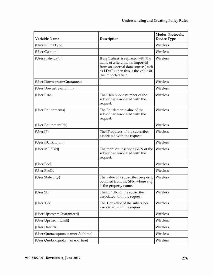
Modes, Protocols,Device TypeDescriptionVariable Name
Wireless{User.BillingType}
Wireless{User.Custom}
WirelessIf customfield is replaced with thename of a field that is imported
{User.customfield}
from an external data source (suchas LDAP), then this is the value ofthe imported field.
Wireless{User.DownstreamGuaranteed}
Wireless{User.DownstreamLimit}
WirelessThe E164 phone number of thesubscriber associated with therequest.
{User.E164}
WirelessThe Entitlement value of thesubscriber associated with therequest.
{User.Entitlements}
Wireless{User.EquipmentIds}
WirelessThe IP address of the subscriberassociated with the request.
{User.IP}
Wireless{User.IsUnknown}
WirelessThe mobile subscriber ISDN of thesubscriber associated with therequest.
{User.MSISDN}
Wireless{User.Pool}
Wireless{User.PoolId}
WirelessThe value of a subscriber property,obtained from the SPR, where propis the property name.
{User.State.prop}
WirelessThe SIP URI of the subscriberassociated with the request.
{User.SIP}
WirelessThe Tier value of the subscriberassociated with the request.
{User.Tier}
Wireless{User.UpstreamGuaranteed}
Wireless{User.UpstreamLimit}
Wireless{User.UserIds}
Wireless{User.Quota.<quota_name>.Volume}
Wireless{User.Quota.<quota_name>.Time}
276910-6402-001 Revision A, June 2012
Understanding and Creating Policy Rules

Modes, Protocols,Device TypeDescriptionVariable Name
Wireless{User.Quota.<quota_name>ServiceSpecific}
Wireless{User.State.Deltas}
Wireless{User.State.EntityStateType}
Wireless{User.State.New}
Wireless{User.State.SequenceNumber}
Wireless{User.State.StateMap}
Wireless{User.State.UpdateMode}
Wireless{User.State.Variables}
AnyThe name (as defined in the CMP)of the device.
{Device.Name}
AnyThe upstream bandwidth capacityof the device.
{Device.UpstreamCapacity}
AnyThe downstream bandwidthcapacity of the device.
{Device.DownstreamCapacity}
AnyThe number of active flows for thedevice.
{Device.FlowCount}
AnyThe name (as defined in the CMP)of the network element associated
{Element.Name}
with the current device. If thedevice is a network element, thenthis is the same as the{Device.Name}. However, if thedevice is contained within anetwork element (as is the case withInterfaces, Channels, and so forth),then this will have a different value.
AnyThe hostname (or IP address) of thenetwork element associated with
{Element.Hostname}
the current device. If the device isa network element, then this is thesame as the {Device.Name}.However, if the device is containedwithin a network element (as is thecase with Interfaces, Channels, andso forth), then this will have adifferent value.
AnyThe hostname (or IP address) of thebackup network element associated
{Element.BackupHostname}
with the current device. If thedevice is a network element, then
277910-6402-001 Revision A, June 2012
Understanding and Creating Policy Rules
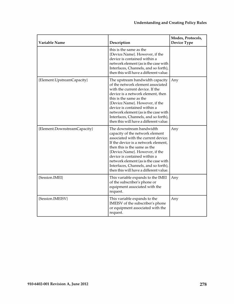
Modes, Protocols,Device TypeDescriptionVariable Name
this is the same as the{Device.Name}. However, if thedevice is contained within anetwork element (as is the case withInterfaces, Channels, and so forth),then this will have a different value.
AnyThe upstream bandwidth capacityof the network element associated
{Element.UpstreamCapacity}
with the current device. If thedevice is a network element, thenthis is the same as the{Device.Name}. However, if thedevice is contained within anetwork element (as is the case withInterfaces, Channels, and so forth),then this will have a different value.
AnyThe downstream bandwidthcapacity of the network element
{Element.DownstreamCapacity}
associated with the current device.If the device is a network element,then this is the same as the{Device.Name}. However, if thedevice is contained within anetwork element (as is the case withInterfaces, Channels, and so forth),then this will have a different value.
AnyThis variable expands to the IMEIof the subscriber's phone or
{Session.IMEI}
equipment associated with therequest.
AnyThis variable expands to theIMEISV of the subscriber's phone
{Session.IMEISV}
or equipment associated with therequest.
278910-6402-001 Revision A, June 2012
Understanding and Creating Policy Rules

Chapter
21Managing Policy Rules
Policy rules are created and saved within the CMPand then deployed to MPE devices. The CMP lets
Topics:
• Displaying a Policy.....280 you create and modify the details within the policies,• Deploying Policy Rules.....281 as well as edit the order in which policy rules are
applied to a protocol message.• Modifying and Deleting a Policy.....283To create policy rules, see Understanding and CreatingPolicy Rules. Managing Policy Rules describes how to
• Policy Templates.....284• Managing a Policy Group.....287
manage your library of policy rules and policygroups.
• Importing and Exporting Policies, Policy Groups,and Templates.....294
• Managing Policy Checkpoints.....295
279910-6402-001 Revision A, June 2012
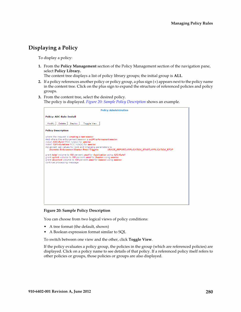
Displaying a Policy
To display a policy:
1. From the Policy Management section of the Policy Management section of the navigation pane,select Policy Library.The content tree displays a list of policy library groups; the initial group is ALL.
2. If a policy references another policy or policy group, a plus sign (+) appears next to the policy namein the content tree. Click on the plus sign to expand the structure of referenced policies and policygroups.
3. From the content tree, select the desired policy.The policy is displayed. Figure 20: Sample Policy Description shows an example.
Figure 20: Sample Policy Description
You can choose from two logical views of policy conditions:
• A tree format (the default, shown)• A Boolean expression format similar to SQL
To switch between one view and the other, click Toggle View.
If the policy evaluates a policy group, the policies in the group (which are referenced policies) aredisplayed. Click on a policy name to see details of that policy. If a referenced policy itself refers toother policies or groups, those policies or groups are also displayed.
280910-6402-001 Revision A, June 2012
Managing Policy Rules

Deploying Policy Rules
Deploying a policy (or policy group) is the act of transferring the policy from the CMP to an MPEdevice. Once deployed, the policy rules defined within the policy or policy group are used asdecision-making criteria by the MPE device.
Figure 21: Policy Deployment shows how policies P1 through P7 are created on the CMP and thendeployed individually to different MPE devices within the network. Each of the policies is associatedindividually with the MPE device where it is deployed. In the example, each policy server (MPEdevice) displays the policies that have been deployed to it and the order in which they are applied topolicy requests, from top to bottom.
Figure 21: Policy Deployment
Figure 22: Policy Group Deployment shows how the same library of policies can be grouped first andthen deployed as policy groups. When a policy group is created, the policies are arranged in the orderin which they are to be evaluated. Grouping policies makes deployment of multiple policies easierand helps to ensure consistency in how policies are applied to policy requests on different MPE devices.
281910-6402-001 Revision A, June 2012
Managing Policy Rules

Figure 22: Policy Group Deployment
When you first create a policy rule, that rule exists only within the CMP policy database. Once thepolicy rule is deployed, any change to the policy rule is automatically redeployed when you completeyour changes. Automatic redeployment also applies to policy groups as well: any change to a policygroup triggers automatic redeployment. If you add a policy rule that was not previously deployed toa policy group that is deployed to one or more MPE devices, then the rule is deployed automaticallyto those MPE devices.
Figure 23: Policy Redeployment shows that when a policy (P3) is modified, its associated groups (PG-1and PG-3) are redeployed automatically.
282910-6402-001 Revision A, June 2012
Managing Policy Rules

Figure 23: Policy Redeployment
When a policy rule is used as a reference policy, you do not need to deploy it; it is deployedautomatically when called by a parent, or top-level, policy.
Modifying and Deleting a Policy
Policies can be modified and then redeployed to MPE devices. When a policy that resides in multiplepolicy groups is modified, the changes are propagated to the various groups.
Modifying a Policy
To modify an existing policy:
1. From the Policy Management section of the navigation pane, select Policy Library.The content tree displays a list of policy library groups; the initial group is ALL.
2. From the content tree, select the ALL group.The Policy Administration page opens in the work area, listing the available policies.
3. Select the policy you want to edit.The Policy Administration page displays information about the policy.
4. Click Modify.The policy wizard opens in a Modify Policy tab.
283910-6402-001 Revision A, June 2012
Managing Policy Rules

5. Edit the desired policy information.See Creating a New Policy for details on the fields within the policy wizard.
6. When you finish, click Finish (or Cancel to discard your changes).
The policy is modified. The modified policy is now ready to be added to a policy group (see Addinga Policy to a Policy Group), or deployed to one or more MPE devices (see Deploying a Policy or PolicyGroup to MPE Devices).
Note: Redeployment of a policy is automatically performed to those MPE devices where the policywas initially deployed.
Deleting a Policy
Policies, policies within a policy group, and entire policy groups can be removed from an MPE devicewhen they are no longer needed. Because the policy still resides on the CMP, it can be redeployed ata later date if needed. If a policy is no longer needed, it can be deleted from the CMP as well.
Note: Deleting a policy from the CMP automatically removes the policy from all associated MPEdevices.
To delete a policy:
1. From the Policy Management section of the navigation pane, select Policy Library.The content tree displays a list of policy groups; the initial group is ALL.
2. From the content tree, select the ALL group.The Policy Administration page opens in the work area, displaying all defined policies.
3. Use one of the following methods to select the policy to delete:
• From the work area, click the Delete icon located to the right of the policy you want to delete.• From the policy group tree, select the policy; the Policy Administration page opens. Click Delete.
You are prompted: “Are you sure you want to delete this Policy?”
4. Click OK to delete the policy (or Cancel to cancel the request).
The policy is deleted.
To remove a deployed policy from an MPE device, see Removing a Policy or Policy Group from an MPEDevice.
Policy Templates
The CMP lets you create policy templates to simplify the creation of multiple policies with similarconditions and actions. A policy template is similar to a policy, except that some (or all) of theparameters in the conditions and actions are not completely defined. Those parameters are definedlater, when you use the policy template to create policy rules.
The policy template wizard is used to create or modify a policy template. This wizard is similar to thepolicy wizard; however, the policy template wizard allows parameters to be only partially defined.For example, a template may only be configured for policy requests requiring bandwidth above acertain value, but not define the exact bandwidth value. You can then specify a specific bandwidthvalue when you use the template to create the new policy rule.
284910-6402-001 Revision A, June 2012
Managing Policy Rules
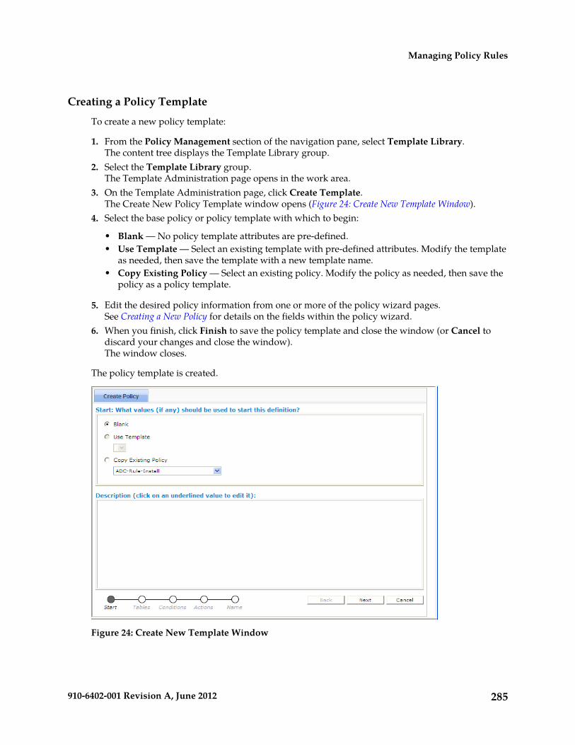
Creating a Policy Template
To create a new policy template:
1. From the Policy Management section of the navigation pane, select Template Library.The content tree displays the Template Library group.
2. Select the Template Library group.The Template Administration page opens in the work area.
3. On the Template Administration page, click Create Template.The Create New Policy Template window opens (Figure 24: Create New Template Window).
4. Select the base policy or policy template with which to begin:
• Blank — No policy template attributes are pre-defined.• Use Template — Select an existing template with pre-defined attributes. Modify the template
as needed, then save the template with a new template name.• Copy Existing Policy — Select an existing policy. Modify the policy as needed, then save the
policy as a policy template.
5. Edit the desired policy information from one or more of the policy wizard pages.See Creating a New Policy for details on the fields within the policy wizard.
6. When you finish, click Finish to save the policy template and close the window (or Cancel todiscard your changes and close the window).The window closes.
The policy template is created.
Figure 24: Create New Template Window
285910-6402-001 Revision A, June 2012
Managing Policy Rules

Modifying a Policy Template
You can edit a policy template to make changes. Modifying a policy template does not modifypreviously configured policies.
To modify an existing policy template:
1. From the Policy Management section of the navigation pane, select Template Library.The content tree displays the Template Library group.
2. Select the Template Library group.The Template Administration page opens in the work area.
3. Select the template you want to modify.The Template Administration page displays a description of the template.
4. Click Modify.The Modify Policy tab opens with the last step of the template creation process. Figure 25: ModifyPolicy Template Window shows an example.
5. Click Back to return to where you want to edit the template and modify the desired information.6. When you finish, click Finish to save the modified template (or Cancel to discard your changes).
The window closes.
The template is modified.
Figure 25: Modify Policy Template Window
Deleting a Policy Template
To delete a policy template:
1. From the Policy Management section of the navigation pane, select Template Library.
286910-6402-001 Revision A, June 2012
Managing Policy Rules

The Template Administration page opens in the work area, displaying all defined policy templates.2. Use one of the following methods to select the policy template to delete:
• From the work area, click the Delete icon, located to the right of the policy template you wantto delete.
• From the template library, select the template; the Template Administration page displays thetemplate. Click Delete.
You are prompted: “Are you sure you want to delete this template?”3. Click OK to delete the policy template (or Cancel to cancel the request).
The policy template is deleted.
Managing a Policy Group
The CMP lets you create policy groups. Policy groups are an organizational aid that provide for flexiblepolicy management, deployment, and execution. Policies are saved to a group in the order in whichthe MPE device applies them to a policy request. If needed, you can change that order. You can savea policy to multiple policy groups and add a policy to, or remove it from, a policy group at any time.
Creating a Policy Group
To create a new policy group:
1. From the Policy Management section of the navigation pane, select Policy Library.The content tree displays a list of policy library groups; the initial group is ALL.
2. From the content tree, select the ALL group.The Policy Administration page opens in the work area, listing available policies.
3. On the Policy Administration page, click Create Group.The group naming field opens in the work area; for example:
287910-6402-001 Revision A, June 2012
Managing Policy Rules

4. Enter the name to assign to the new group, then click Save (or Cancel to discard your changes).
The new group information is saved to the CMP and displayed in the content tree.
Adding a Policy to a Policy Group
To add one or more policies to a policy group:
1. From the Policy Management section of the navigation pane, select Policy Library.The content tree displays a list of policy library groups; the initial group is ALL.
2. From the content tree, select the policy group to which you want to add the policy.The Policy Administration page opens in the work area, listing the policies currently in the group.
3. On the Policy Administration page, click Modify.The Policy Administration page opens in the work area; for example:
288910-6402-001 Revision A, June 2012
Managing Policy Rules

4. Click Add Policy.A window opens, displaying the policies available; for example:
5. Select the desired policy or policies to add to this group and click Add (or Cancel to cancel therequest).The policies are added to the policy group and the window closes.
Note: Policies are applied to messages in the order in which they appear in the policy group. Youcan change the sequential order as desired (see Changing the Sequence of Deployed Policy Groups).
6. When you finish, click Save (or Cancel to discard your changes).The added policies are displayed in the policy group tree.
Now you can deploy the policy group to the policy servers (see Deploying a Policy or Policy Group toMPE Devices).
Note: If this group had been deployed previously, it is automatically redeployed at this time, ensuringthe MPE devices are resynchronized with the CMP.
289910-6402-001 Revision A, June 2012
Managing Policy Rules

Removing a Policy from a Policy Group
Removing a policy from a policy group that has been saved to the CMP only removes the policy fromthe selected policy group. The policy itself remains in the ALL group, as well as any other group towhich it had been added. (To remove a policy from all groups in the Policy Library, see Removing aPolicy or Policy Group from an MPE Device.)
To remove a policy from a policy group:
1. From the Policy Management section of the navigation pane, select Policy Library.The content tree displays a list of policy library groups; the initial group is ALL.
2. From the content tree, select the desired policy group.The Policy Administration page opens in the work area, listing the policies it contains.
3. Remove the desired policy using one of the following methods:
• From the content tree, select the desired policy within the policy group; its profile informationis displayed. Click Remove.
• From the content tree, select the desired policy group and click Modify. Select the remove icon,located to the right of the policy you want to remove.
290910-6402-001 Revision A, June 2012
Managing Policy Rules

After a policy is removed from a policy group, the modified group is ready to be deployed to MPEdevices (see Deploying a Policy or Policy Group to MPE Devices).
Note: This modified policy group is redeployed at this time, ensuring that the MPE devices areresynchronized with the CMP system.
Changing the Sequence of Policies Within a Policy Group
The order in which policies appear in a policy group is the order in which they are deployed andapplied to policy requests. You can modify the order of policies, both inside and outside of a policygroup.
To change the order of the policies within a group:
1. From the Policy Management section of the navigation pane, select Policy Library.The content tree displays a list of policy library groups; the initial group is ALL.
2. From the content tree, select the desired policy group.The Policy Administration page opens in the work area, displaying policies in their current sequentialorder.
3. On the Policy Administration page, click Modify.The Manage Policies page opens.
4. Use the up and down arrow icons, located to the right of policies, to change the sequence of policieswithin the group.
5. When you finish, click Save (or Cancel to discard your changes).
The modified group is ready to be deployed to MPE devices (see Deploying a Policy or Policy Group toMPE Devices).
Note: This modified group is redeployed at this time, ensuring that the MPE devices are resynchronizedwith the CMP.
Displaying Policy Details Contained Within a Policy Group
To display the policies within a policy group:
1. From the Policy Management section of the navigation pane, select Policy Library.The content tree displays a list of policy library groups; the initial group is ALL.
2. From the content tree, select the desired policy group.The Policy Administration page opens in the work area, listing the policies it contains.
3. Click Show Details.The configured policies, including the configured parameters for the policies, are displayed. Toswitch between logical views of policy conditions, click Toggle View .
4. When you finish, click Cancel.
Deploying a Policy or Policy Group to MPE Devices
The basic procedure for deploying either a policy or a policy group to MPE devices is the same. Thefollowing procedure uses the example of deploying a policy group:
1. From the Policy Management section of the navigation pane, select Policy Library.The content tree displays a list of policy library groups; the initial group is ALL.
291910-6402-001 Revision A, June 2012
Managing Policy Rules

2. From the content tree, select the policy group to deploy.The Policy Administration page opens in the work area, listing the policies it contains.
3. On the Policy Administration page, click Deploy.The policy server tree is displayed, listing all possible target policy servers (MPE devices) andserver groups. You can expand the tree view if necessary.
4. Select the desired target MPE devices or server groups.
5. Click Deploy (or Cancel to cancel the request).
The policy information is saved to each selected MPE device. A message confirms that the deploymentprocess was successful.
Removing a Policy from a Policy Group on an MPE Device
To remove a policy from within a policy group that was deployed to an MPE device, the policy groupis modified on the CMP system, then redeployed. (To remove an entire policy group from an MPEdevice, see Removing a Policy or Policy Group from an MPE Device.)
To remove a policy from a policy group and then redeploy the group:
1. From the Policy Management section of the navigation pane, select Policy Library.The content tree displays a list of policy library groups; the initial group is ALL.
2. From the content tree, select the desired policy group.The Policy Administration page opens in the work area, listing the policies the group contains.
3. Remove the desired policy using one of the following methods:
• From the Policy Library tree, select the policy. The Policy Administration page displays theprofile information. Click Remove.
292910-6402-001 Revision A, June 2012
Managing Policy Rules

• On the Policy Administration page, click Modify and then select the Remove icon located nextto the policy you want to remove.
Removing a Policy or Policy Group from an MPE Device
Removing a deployed policy or policy group from an MPE device is performed from the Policy ServerAdministration page.
To remove a policy/policy group from an MPE device:
1. From the Policy Server section of the navigation pane, select Configuration.The content tree displays a list of policy server groups; the initial group is ALL.
2. From the content tree, select the MPE device.The Policy Server Administration page opens in the work area, displaying information about theMPE device.
3. On the Policy Server Administration page, select the Policies tab.
293910-6402-001 Revision A, June 2012
Managing Policy Rules

4. Click Modify.The Manage Policies page opens.
5. Click the Remove icon, located to the right of the policy or policy group that you want to remove.6. When you finish, click Save (or Cancel to cancel the request).
The policy or policy group is redeployed to the MPE device, minus the removed policy or policygroup.
Changing the Sequence of Deployed Policy Groups
Changing the sequential order of deployed policy groups is performed directly on an MPE deviceusing the Policy Server Administration page.
To change the sequential order of policy groups:
1. From the Policy Server section of the navigation pane, select Configuration.The content tree displays a list of policy server groups; the initial group is ALL.
2. From the content tree, select the MPE device.The Policy Server Administration page opens in the work area, displaying information about theMPE device.
3. On the Policy Server Administration page, select the Policies tab.4. Click Modify.
The Manage Policies page opens in the work area.5. Use the up and down arrow icons, located to the right of each policy group, to change the sequential
positioning of the policy groups.6. When you finish, click Save (or Cancel to cancel the request).
The policy groups are redeployed to the MPE device in their new sequential order. A confirmationmessage displays in the work area.
Importing and Exporting Policies, Policy Groups, and Templates
Policies, policy groups, and templates can be exported from the CMP for inspection or backup purposes.These items are exported as a whole and cannot be exported individually, as every policy, policygroup, and policy template that resides on the CMP is saved to a single file when performing theexport function.
For information only, exported policies are marked with policy version numbers as well as the versionnumber of the CMP software under which they were created. This does not affect importation ofpolicies created under different versions of the CMP.
Importing Policies
To import a policy file to the CMP:
1. From the Policy Management section of the navigation pane, select Policy Import / Export.The Import/Export page opens.
2. On the Import/Export page, click Browse to locate the policy file to import.
294910-6402-001 Revision A, June 2012
Managing Policy Rules

3. Select the desired collision handling option:
• Delete all before importing — All policies, policy groups, and templates currently on the CMPare deleted first; then the imported versions are saved to the MPE device.
• Overwrite with imported version — All items are imported. If the CMP currently contains anypolicies, policy groups, or templates using the same names as the ones being imported, theyare overwritten with the imported versions.
• Reject any that already exist — All items are imported except for imported versions with thesame name as any policy, policy group, or template currently on the CMP.
• Any collisions prevent all importing — No items are imported if any of the imported versionshas the same name as any policy, policy group, or template currently on the CMP. This is thedefault.
4. Click Import.
The policies are imported.
If you try to import an invalid file you receive a validation error: “You must correct the followingerror(s) before proceeding: There is a problem with the import file. The name is required, the file mustbe present, and the file must be in the correct format.”
Exporting Policies
To export the policies or policy templates that reside in the policy library:
1. From the Policy Management section of the navigation pane, select Policy Import / Export.The Import/Export page opens.
2. Select the type of export: Policies (the default) or Templates.3. Select the policy group to export: All (the default) or a named group.4. Click Export to export the policy group in XML format, or Text to export the policy group in
descriptive format. Policies exported in text format cannot be reimported.A standard File Download window opens.
5. Click Save (or Cancel to close the window and cancel the request).A standard Save As window opens.
6. Assign a name to the policy file (the default is PolicyExport.xml), use the browse function to mapto the desired location, and click Save.When the policies are successfully exported, a standard Download Complete window opens.
7. Select Close to close the Download Complete window.
The policies or templates are exported to a file.
Managing Policy Checkpoints
A policy checkpoint is a method of saving the records in the CMP at a specific point in time. Recordssaved are policies, policy groups, policy templates, policy tables, retry profiles, service profiles, trafficprofiles, and traffic profile groups. Related profiles are not saved. You can save up to ten checkpoints.
Once a checkpoint is created, you can return to this set of records at any time by restoring thecheckpoint.
295910-6402-001 Revision A, June 2012
Managing Policy Rules

CAUTION: When you restore a checkpoint, all existing data is permanently removed.
The checkpoint function is different from the export/import function in these ways:
• Checkpoints are saved on the CMP server rather than to a file.• A checkpoint saves all records mentioned above; the import/export feature allows you to select
which records to import or export.• A checkpoint can only be used on a specific CMP, and cannot be migrated to another CMP system.
To see this feature on the GUI menu and be able to use it, a value other than 0 must be specified forthe Allow policy backup and rollback field on the Configuring System Settings page. This field alsocontrols the maximum number of checkpoints that can be saved.
Viewing and Comparing Policy Checkpoints
Use this procedure to view all checkpoints and/or compare a selected checkpoint's records to thecurrent CMP records. You can also view the records saved for a specific checkpoint.
To view/compare policy checkpoints in the CMP:
1. From the Policy Management section of the navigation pane, select Policy Checkpoint/Restore.The Checkpoint/Restore page opens.
2. Click Diff to view a report that compares the selected checkpoint's records to the current CMPrecords.
3. Click More Info to view a list of all required profile names for this checkpoint. These profiles mustexist in the system before a checkpoint is restored, otherwise the restore will fail.
Creating a Policy Checkpoint
Use this procedure to create a new checkpoint. A checkpoint saves policies, policy groups, policytemplates, traffic profiles, and traffic profile groups; related profiles are not saved.
Note that the maximum number of checkpoints that can be created is defined on the System Settingspage. If you create more than the number defined, the oldest checkpoint is deleted.
To create a new policy checkpoint in the CMP:
1. From the Policy Management section of the navigation pane, select Policy Checkpoint/Restore.The Checkpoint/Restore page opens.
2. Click Create a new checkpoint.If the maximum number of checkpoints already exists, the message, X checkpoints already exist,by creating this checkpoint the oldest one will be deleted. Continue? appears (where X is themaximum number of checkpoints).
To add the new checkpoint click OK, or click Cancel to exit the checkpoint creation process.
When the checkpoint is created, the message, Checkpoint successfully added appears in green onthe screen.
296910-6402-001 Revision A, June 2012
Managing Policy Rules

Restoring a Policy Checkpoint
CAUTION: All current records are lost when a restore is performed. It is recommendedthat you save a checkpoint before restoring a previous checkpoint.
Use this procedure to return to a saved checkpoint. A checkpoint saves policies, policy groups, policytemplates, traffic profiles, and traffic profile groups.
Note: Profiles are not saved in checkpoints, so be sure all related profiles exist in the CMP beforerestoring. If a related profile is not available before you do a restore, the restore process will fail. Usethe More Info link to view all required profiles for a checkpoint.
To restore to a checkpoint in the CMP without autodeployment to the MPEs:
1. From the Policy Management section of the navigation pane, select Policy Checkpoint/Restore.The Checkpoint/Restore page opens.
2. Click the radio button associated with the checkpoint you are restoring.3. Click Restore to restore the selected checkpoint.
A pop-up dialog box appears with the message, Caution: You'd better save a checkpoint beforeany restoration.
4. Click Cancel to exit (if you need to create a checkpoint) or OK to continue.If you click OK, a pop-up dialog box appears with the message, Are you sure that you want torestore this checkpoint?
5. Click OK.The selected checkpoint is restored.
A restored checkpoint message appears, listing which policies and policy groups were restored andwhich were removed.
Restoring a Policy Checkpoint to MPEs
CAUTION: All current records are lost when a restore is performed. It is recommendedthat you save a checkpoint before restoring a previous checkpoint.
Note: Profiles are not saved in checkpoints, so be sure all related profiles exist in the CMP beforerestoring. If a related profile is not available before you do a restore, the restore process will fail. Usethe More Info link to view all required profiles for a checkpoint.
To restore to a checkpoint in the CMP and autodeploy to all MPEs in the system:
1. From the Policy Management section of the navigation pane, select Policy Checkpoint/Restore.The Checkpoint/Restore page opens.
2. Click the radio button associated with the checkpoint you are restoring.3. Click Restore & Deploy to restore records to the selected checkpoint.
A pop-up dialog box appears with the message, Caution: You'd better save a checkpoint beforeany restoration.
4. Click Cancel to exit (if you need to create a checkpoint) or OK to continue.
297910-6402-001 Revision A, June 2012
Managing Policy Rules

If you click OK, a pop-up dialog box appears with the message, Are you sure that you want torestore this checkpoint and deploy to the MPEs?
5. Click OK.The selected checkpoint is restored and deployed to the MPEs.
A restored checkpoint message appears, listing which policies and policy groups were restored, whichwere removed, and to which MPEs the deployment succeeded.
Deleting a Policy Checkpoint
To delete a saved checkpoint from the CMP:
1. From the Policy Management section of the navigation pane, select Policy Checkpoint/Restore.The Checkpoint/Restore page opens.
2. Click the radio button associated with the checkpoint you are deleting.3. Click Delete the selected checkpoint to remove the checkpoint from the system.
A pop-up dialog box appears with the message, Are you sure you want to delete this Checkpoint?4. Click OK.
The message, Checkpoint deleted successfully appears in green on the screen.
The selected checkpoint is deleted from the system.
298910-6402-001 Revision A, June 2012
Managing Policy Rules

Chapter
22Managing Policy Tables
Managing Policy Tables describes how to create,modify, delete, and view independent objects whichare used to capture differences in policy structures.
Topics:
• About Policy Tables.....300• Creating Policy Tables.....300 You can manage multiple policies with small
differences by abstracting the policies into tables.• Modifying Policy Tables.....301• Deleting Policy Tables.....301 The process of modifying the policies then becomes
simpler and less prone to error.• Viewing Policy Tables.....302
299910-6402-001 Revision A, June 2012

About Policy Tables
APNs have a unique charging-rule name which is applicable to home or roaming usage. The rule mustbe mapped for the flow and session of devices. The following table describes the possible table-drivenpolicy examples.
Table 9: ChargingRuleInstall OnNet
DescriptionName
CRule Table02 - ApnChargingRuleList
Device Specific flow or session, where the APNmatches one of [CRuleTable.CalledStationId]. The
02 - Scope
serving MCC-MNC matches one of 26207. Thedevice name matches one of [scope.DeviceName].Install [CRuletable.charging profile on_net] PCCrule(s) for [scope.flowOrsession] continueprocessing message
Table 10: ChargingRuleInstall OffNet
DescriptionName
CRule Table02 - ApnChargingRuleList
Device Specific flow or session, where the APNmatches one of [CRuleTable.CalledStationId]. The
02 - Scope
serving MCC-MNC matches one of 26207. Thedevice name matches one of [scope.DeviceName].Install [CRuletable.charging profile off_net] PCCrule(s) for [scope.flowOrsession] continueprocessing message
Creating Policy Tables
1. From the Policy Management section of the navigation pane, select Policy Table Library.The content tree displays the Policy Table Library group.
2. Select the Policy Table Library group.The Policy Table Administration page opens in the work area.
3. On the Policy Table Administration page click Create Policy Table.The New Policy Table Administration page opens.
4. Enter information as appropriate for the Policy Table:a) Name (required) — The name you assign to the policy table.
The name can be up to 255 characters long and must not contain quotation marks (") or commas(,).
300910-6402-001 Revision A, June 2012
Managing Policy Tables

b) Description/Location (required) — Free-form text that identifies the policy table.
5. Click Add Row or Add Column — (required) At least one key column must be selected.If Add Column is selected, you must populate the following definitions in the Policy Table columnpop-up:
• Column Name (required) — The name you assign for the column.• Key (required) — A check box and entry field which indicates that this is a key column.• Column Type (required) — The folder icon when clicked opens the wizard, which displays the
optional actions and conditions. Select your fields of choice from an action or condition.
Your column name, key, type, actions, and conditions are selected.6. Click Operations — You can perform the following from the pulldown list:
• Delete Row — Deletes the table row.• Move Row Up — Moves the table row up.• Move Row Down — Moves the table row down.• Delete Column — Deletes the column in the table.• Move Column Left — Moves the column left in the table.• Move Column Right — Moves the column right in the table.• Sort Column — Sorts the column in the table.• UnSort Column — Reverts the column to its original order.
7. Click Validate. If selected, the data modified is validated. If invalid, a diagnostic message appears.The Policy Table is displayed on the Policy Table Administration page.
8. When you finish, click Save (or Cancel to discard your changes).
Modifying Policy Tables
1. From the Policy Management section of the navigation pane, select Policy Table Library.The Policy Table Administration page opens in the work area.
2. On the Policy Table Administration page, select the policy table you want to modify.The Policy Table Administration page displays information about the policy table.
3. Click Validate. If selected, the data modified is validated. If invalid, a diagnostic message appears.4. Click Modify.
The table fields become editable. See Creating Policy Tables for information about the table fields.5. When you finish, click Save (or Cancel to discard your changes).
The policy table content is modified.
Deleting Policy Tables
1. From the Policy Management section of the navigation pane, select Policy Table Library.The Policy Table Administration page opens in the work area.
301910-6402-001 Revision A, June 2012
Managing Policy Tables

2. Delete the Policy Table using one of the following methods:
• From the work area, click the Delete icon located to the left of the Policy Table name you wishto delete..
• Open the policy and click Delete.
You are prompted: "Are you sure you want to delete this policy table?"3. Click OK (or Cancel to cancel the request).
The policy table is deleted.
Viewing Policy Tables
From the Policy Management section of the navigation pane, select Policy Table Library.A tree frame view of all existing policy tables. You will see all of the existing policy tables in themain frame when you click ALL.
Note: The policy table details are viewed by clicking the actual policy table name in the tree frame.
302910-6402-001 Revision A, June 2012
Managing Policy Tables

Chapter
23Managing Subscribers
Managing Subscribers describes how to create andmanage subscriber tiers and quota usage within theCMP.
Topics:
• Creating a Tier.....304• Deleting a Tier.....304 Note: For information about the Subscriber Profile
Repository (SPR), see the Tekelec Subscriber DataManagement documentation.
• Managing Sessions.....305
303910-6402-001 Revision A, June 2012

Creating a Tier
Tiers are categories that you can define and then apply to groups of subscribers. For example, you cancreate a series of tiers with different bandwidth limits. Once you define tiers, you can use them inpolicy rules.
To create a subscriber tier:
1. From the Subscriber section of the navigation pane, select Tiers.The content tree displays the Tiers folder.
2. Select the Tiers folder.The Tier Administration page opens.
3. Click Create Tier.The New Tier page opens.
4. Enter information as follows:a) Name (required) — Name of the tier.
The name can be up to 255 characters long and must not contain quotation marks (") or commas(,).
b) Description/Location — Free-form text.Enter up to 250 characters.
c) Downstream bandwidth limit (bps) — The maximum amount of bandwidth capacity availablein the downstream direction in bits per second.You can enter a value followed by M or G; for example, 4G for 4 gigabits per second.
d) Upstream bandwidth limit (bps) — The maximum amount of bandwidth capacity availablein the upstream direction in bits per second.You can enter a value followed by M or G; for example, 10M for 10 megabits per second.
5. When you finish, click Save (or Cancel to cancel the request).
The tier is created and applied to MPE devices controlled by this CMP, and the message “Tier createdsuccessfully” is displayed.
Deleting a Tier
To delete a tier:
1. From the Subscriber section of the navigation pane, select Tiers.The Tiers folder appears in the content tree.
2. Delete the tier using one of the following methods:
• From the work area, click the Delete icon, located to the right of the tier you wish to delete.• From the content tree, select the tier and click Delete. You are prompted, “Are you sure you
want to delete this Tier?”
3. Click OK (or Cancel to cancel the request).
304910-6402-001 Revision A, June 2012
Managing Subscribers

The tier is deleted, and the message “Tier deleted successfully” is displayed.
Managing Sessions
You can display static session and binding data for a specific subscriber from the Policy Managementdevice that is managing the session. Depending on how the data is indexed on the device, you cansearch for a subscriber by IMSI, MSISDN, IP address, or NAI. You can also delete obsolete sessions.
Note: This function is not supported by Policy Management devices before V7.5.
To view a session:
1. From the Policy Server section of the navigation pane, select Configuration.The content tree displays a list of policy server groups; the initial group is All.
2. Select the Policy Management device managing the session you are interested in.The Policy Server Administration page opens in the work area.
3. On the Policy Server Administration page, select the Session Viewer tab.The Session Viewer tab opens.
4. Enter search information as follows:a) Identifier type (required) — Select NAI (the default), E.164(MSISDN), IMSI, IPv4Address, or
IPv6Address from the pulldown list.The identifier types you can specify are determined by the configuration of the PolicyManagement device. For example, if the IndexByNAI setting is not specified on the device, thenyou cannot select NAI.
b) Identifier name — Free-form text.Enter up to 250 characters.
5. Click Search.If sessions are available for the subscriber, subscriber session data is displayed. Figure 26: SessionViewer Page shows an example.
If you are viewing subscriber data from a stateful MRA system, subscriber binding data is displayed,including an identifier for the MPE device handling sessions for that subscriber. If that MPE deviceis managed by this CMP device, you can click on the identifier to view session data from the MPEdevice.
Note: If an external system generates data that, when translated to ASCII, creates illegal characters,they are displayed by the Session Viewer as question marks (?).
For each session displayed from an MPE device, you can click Delete Session to delete the session.For each session binding displayed from an MRA device, you can click Delete Binding to delete thebinding. This deletes the record in the appropriate database.
CAUTION: Only obsolete sessions should be deleted. If you delete an active session,there is no signal to any associated gateways or external network elements.
305910-6402-001 Revision A, June 2012
Managing Subscribers

Figure 26: Session Viewer Page
306910-6402-001 Revision A, June 2012
Managing Subscribers

Chapter
24System-Wide Reports
System-Wide Reports describes the reports availableon the function of Policy Management systems in
Topics:
• Viewing Active Alarms.....308 your network. Reports can display platform alarms,• Viewing the Alarm History Report.....309 network protocol events, and Policy Management
application errors.• KPI Dashboard.....310• Viewing the Trending Reports.....332• Viewing the Connection Status Report.....335• Viewing the Protocol Errors Report.....336• Viewing the Policy Statistics Report.....337
307910-6402-001 Revision A, June 2012

Viewing Active Alarms
The Active Alarms report provides an aggregate view of timestamped alarm notifications for PolicyManagement systems. The display is refreshed every ten seconds and appears in the upper right cornerof all CMP pages. Alarms remain active until they are reset.
To view the Active Alarms report, from the System Wide Reports section of the navigation pane,select Active Alarms.
Figure 27: Sample Active Alarms Report shows a sample active alarm report.
Figure 27: Sample Active Alarms Report
The alarm levels are as follows:
• Critical — Service is being interrupted.• Major — Service may be interrupted if the issue is not corrected.• Minor — Non-service affecting fault.
Notification with a severity of Info are not displayed in the Active Alarms report, but are written tothe trace log. For more information, see The Trace Log.
Note: Alarms generated by Policy Management systems running software before V7.5 are mappedto these levels as follows: Emergency or Critical map to Critical; Alert or Error map to Major; Warningor Notice map to Minor.
From the report page you can do the following:
• To sort the report on any column, click the column title.• To select alarms from an individual Policy Management cluster, select it from the Server list.• To select alarms from a class of Policy Management cluster, select All (the default), CMP, MRA,
or MPE from the Server Type list.• To pause the display of alarms, click Pause. To resume the display, click Refresh.
308910-6402-001 Revision A, June 2012
System-Wide Reports

• To filter results by severity, from the Severity list select All (the default) to display alarms of allseverities, Major to display alarms of severity Major, or Minor to display alarms of severity Minor.
• To reformat the report for printing, click Printable Format.• To save the report in comma-separated-value (spreadsheet) format, click Save as CSV.• To save the report as a Portable Document Format (PDF) file, click Export PDF.
Viewing the Alarm History Report
The Alarm History Report displays historical alarm information.
To view the alarm history report, from the System Wide Reports section of the navigation pane, selectAlarm History Report.
You can define filtering criteria using the following fields:
• Start Date — Filter out alerts before a specific date/time. Click the calendar icon to specify adate/time.
• End Date — Filter out alerts after a specific date/time. Click the calendar icon to specify a date/time.• Severity — Filter alerts by severity level; select a level (the default is All) from the list.• Cluster or Server — Select the cluster or server within the cluster whose alarms you want to view.• Active Alarms — Select to view only active alarms; the default is to display both active and cleared
alarms.• Aggregate — Select to aggregate alarms that have the same IP address, alarm ID, and severity.
After entering filtering information, click Filter to refresh the display with the filtering applied.
When you finish, click Close to close the window.
Alarms contain the following information:
• Occurrence — The most recent time this alert was triggered.• Severity — The severity of the alert:
• Critical — Service is being interrupted.• Major — Service may be interrupted if the issue is not corrected.• Minor — Non service affecting fault.• Info — Informational message only.• Clear — Alarm has been cleared.
Note: Alarms generated by Policy Management systems running software before V7.5 are mappedto these levels as follows: Emergency or Critical map to Critical; Alert or Error map to Major;Warning or Notice map to Minor.
• Text — User-readable text of the alert.• OAM VIP — OAM IP address or IPv4 address• Server — IP address, in IPv4 or IPv6 format, or FQDN of the device from which this alarm was
generated.• Alarm ID— When clicked, the alarm ID provides online help information.
To view alert details, click the binoculars icon, located to the right of the alert. A window displaysadditional information; for example:
309910-6402-001 Revision A, June 2012
System-Wide Reports

Click Cancel to close the window.
KPI Dashboard
The KPI Dashboard provides a multi-site system-level summary of performance and operationalhealth indicators in the CMP's web-based GUI. The display includes indicators for:
• Offered load (transaction rate)• System capacity (counters for active sessions)• Inter-system connectivity• Physical resource utilization (memory, CPU)• System status• Alarms• Protocol errors
The KPI dashboard displays the indicators for all the systems on a single page, with each MRA’s KPIsin a separate table when MRAs are managed by the CMP or with all MPE's KPIs in one table whenMRAs are not managed by the CMP (e.g. MPE-only deployment). Each row within a table representsa single system (either an MPE or MRA server). The table cells are rendered using a color scheme tohighlight areas of concern that is well adopted by the telecommunication industry. The table contentsare periodically refreshed every 10 seconds; this time period is not configurable. The color changingthresholds are user configurable.
Figure 28: Example of KPI Dashboard with MRAs Managed by the CMP illustrates the dashboard’s contentswhen MRAs are managed by the CMP.
310910-6402-001 Revision A, June 2012
System-Wide Reports

Figure 28: Example of KPI Dashboard with MRAs Managed by the CMP
When MRAs are not managed by the CMP, the displayed headings are:
• Name/MPE• Performance:
• State• TPS• Sessions• CPU %• Memory %
• Connections
• SPR• Network Elements
• Alarms
• Critical• Major• Minor
• Protocol Errors
• Sent• Received
In the top right corner there is a Change Thresholds button that allows you to change threshold settingsused to determine cell coloring (discussed below). When MRAs are managed by the CMP, a buttonon the top left corner lists each of the MRAs with a checkbox that allows the user to enable/disablethe table for that MRA.
Each MRA or MPE system has three rows in the table. The first row displays information for the activeserver, Server A, in the cluster. The second row displays information for the standby server, Server
311910-6402-001 Revision A, June 2012
System-Wide Reports

B, in the cluster, if present. And the third row displays information for the spare server, Server C, ifpresent. If any of these are set to Reverse Site Preference, then an "R" will appear by the server's State.Several of the KPI columns are not populated for the standby or spare server (since the server is notactive). The only columns that contain data are: Status, CPU%, and Memory%. For Connections,Alarms, and Protocol Errors, the column's information is a hyperlink that will open a more detailedreport.
If a monitored system is unreachable, or if the data is unavailable for some reason, then the status isset to "Off-line" and the values in all the associated columns is cleared. In this situation, the entire rowis displayed with the error color (red). If a monitored system does not support KPI retrieval then thestatus is set to "N/A" and the values in all the associated columns are cleared. No coloring is applied.
The columns that display information in the form of X (Y%) (e.g. "TPS" and "PDNConnections"/"Sessions") correspond to the following: X represents the actual numeric value and Yrepresents the % of rated system capacity that is consumed.
The columns that display connection counts are displayed in the form "X of Y" where X is the currentnumber of connections and Y is the configured number of connections. When X and Y are not thesame, the column uses the warning color to indicate a connectivity issue, unless X is 0, in which casethe error color is displayed.
The Alarm and Protocol Errors columns display the number of current events. If there are any Criticalor Major alarms, then these cells will be colored red or yellow, respectively.
Note: To learn more about an alarm and how to resolve it, see the Policy Management TroubleshootingGuide for this release.
Click on the name of an MPE or MRA device to display detailed statistics. For more information ondetailed device statistics, see the description of the Reports tab for the device.
Mapping Display to KPIs
The following tables explain how each of the columns in the KPI dashboard are mapped to a specificstatistic in the KPI statistics. On the initial KPI Dashboard window, KPIs for each MRA and MPE areshown. Since the tables contain row entries for the active, standby and spare servers (if georedundancyis configured), the mapping is described for all three servers. Table 11: KPI Definitions for MRA showsthe mappings for MRAs; Table 12: KPI Definitions for MPE when MRAs are Managed by CMP shows themappings for MPEs when the MRAs are managed by the CMP; and Table 13: KPI Definitions for MPEwhen MRAs are not Managed by CMP shows the mappings for MPEs when the MRAs are not managedby the CMP.
Table 11: KPI Definitions for MRA
Mapping to Statistics
KPIDashboardColumn
Standby and spare server (spare onlyshows Status, CPU % and Memory%)
Active server
Not derived from statistics.Not derived from statistics.Name
Label representation of theSecondaryServerStatus
Label representation of thePrimaryServerStatus
State
312910-6402-001 Revision A, June 2012
System-Wide Reports

Mapping to Statistics
KPIDashboardColumn
NoneCurrentTransactionsPerSecond andCurrentTPSPercentageOfCapacity
TPS
NoneCurrentPDNConnectionCount andCurrentPDNConnectionPercentageOf
Capacity
PDNConnections
NoneCurrentMRABindingCount andCurrentMRABindingPercentageOfCapacity
ActiveSubscribers
SecondaryCPUUtilizationPercentagePrimaryCPUUtilizationPercentageCPU %
SecondaryMemoryUtilizationPercentagePrimaryMemoryUtilizationPercentageMemory %
NoneA value in the form "X of Y", where:MPEConnections
X is CurrentMPEConnectionCount
Y is ConfiguredMPEConnectionCount
NoneA value in the form "X of Y", where:MRAConnections
X is CurrentMRAConnectionCount
Y is ConfiguredMRAConnectionCount
NoneA value in the form "X of Y", where:NetworkElementConnections X is CurrentConnectedNECount
Y is ConfiguredNECount
Not derived from statisticsNot derived from statisticsCriticalAlarms
Not derived from statisticsNot derived from statisticsMajorAlarms
Not derived from statisticsNot derived from statisticsMinorAlarms
NoneCurrentProtocolErrorSentCountProtocolErrors Sent
NoneCurrentProtocolErrorReceivedCountProtocolErrorsReceived
313910-6402-001 Revision A, June 2012
System-Wide Reports

Table 12: KPI Definitions for MPE when MRAs are Managed by CMP
Mapping to Statistics
KPIDashboardColumn
Standby serverActive server
Not derived from statistics.Not derived from statistics.Name
Label representation of theSecondaryServerStatus
Label representation of thePrimaryServerStatus
Status
NoneCurrentTransactionsPerSecond andCurrentTPSPercentageOfCapacity
TPS
NoneCurrentPDNConnectionCount andCurrentPDNConnectionPercentageOf
Capacity
PDNConnections
SecondaryCPUUtilizationPercentagePrimaryCPUUtilizationPercentageCPU %
SecondaryMemoryUtilizationPercentagePrimaryMemoryUtilizationPercentageMemory %
NoneA value in the form "X of Y", where:MRAConnections
X is CurrentMRAConnectionCount
Y is ConfiguredMRAConnectionCount
NoneA value in the form "X of Y", where:HSSConnections
X is CurrentSPRConnectionCount
Y is ConfiguredSPRConnectionCount
Not derived from statisticsNot derived from statisticsCriticalAlarms
Not derived from statisticsNot derived from statisticsMajorAlarms
Not derived from statisticsNot derived from statisticsMinorAlarms
NoneCurrentProtocolErrorSentCountProtocolErrors Sent
NoneCurrentProtocolErrorReceivedCountProtocolErrorsReceived
314910-6402-001 Revision A, June 2012
System-Wide Reports

Table 13: KPI Definitions for MPE when MRAs are not Managed by CMP
Mapping to Statistics
KPIDashboardColumn
Standby serverActive server
Not derived from statistics.Not derived from statistics.Name
Label representation of theSecondaryServerStatus
Label representation of thePrimaryServerStatus
Status
NoneCurrentTransactionsPerSecond andCurrentTPSPercentageOfCapacity
TPS
NoneCurrentSessionCount andCurrentSessionPercentageOfCapacity
Sessions
SecondaryCPUUtilizationPercentagePrimaryCPUUtilizationPercentageCPU %
SecondaryMemoryUtilizationPercentagePrimaryMemoryUtilizationPercentageMemory %
NoneA value in the form "X of Y", where:SPRConnections
X is CurrentSPRConnectionCount
Y is ConfiguredSPRConnectionCount
NoneA value in the form "X of Y", where:NetworkElementConnections X is CurrentConnectedNECount
Not derived from statisticsNot derived from statisticsCriticalAlarms
Not derived from statisticsNot derived from statisticsMajorAlarms
Not derived from statisticsNot derived from statisticsMinorAlarms
NoneCurrentProtocolErrorSentCountProtocolErrors Sent
NoneCurrentProtocolErrorReceivedCountProtocolErrorsReceived
Clicking on an MRA or MPE opens the Reports tab. See the Reports section of the CMP Wireless User'sGuide for details on reports.
Mapping Reports Display to KPIs
From the KPI Dashboard, you can click on any MPE or MRA shown to open the Reports page. Fromthere, a variety of statistics and measurements can be viewed. In the following tables, these statisticsare mapped to the name as it appears in OSSI XML output.
315910-6402-001 Revision A, June 2012
System-Wide Reports

Table 14: Diameter Application Function (AF) Stats
NameMRAMPEDisplay
Conn CountYYConnections
Peer Okay CountYYCurrently OK peers
Peer Down Count\Peer SuspectCount\Peer Reopen Count
YYCurrently down/suspect/reopenedpeers
Msg In Count\Msg Out CountYYTotal messages in/out
AAR Recv Count\AAR Send CountYYAAR messages sent/received
AAR Initial Recv Count\AAR InitialSend Count
YYAAR initial messages recd /sent
AAR Modification Recv Count\AARModification Send Count
YYAAR modification messagesrecd/sent
AAA Recv Success Count\AAA SendSuccess Count
YYAAA success messages recd/sent
AAA Recv Failure Count\AAA SendFailure Count
YYAAA failure messages recd/sent
AAR Timeout CountYYAAR messages timeout
ASR Recv Count\ASR Sent CountYYASR messages recd/sent
ASR Timeout CountYYASR messages timeout
ASA Recv Success Count\ASA SendSuccess Count
YYASA success messages recd/sent
ASA Recv Failure Count\ASA SendFailure Count
YYASA failure messages recd/sent
RAR Recv Count\RAR Send CountYYRAR messages recd/sent
RAR Timeout CountYYRAR messages timeout
RAA Recv Success Count\RAA SendSuccess Count
YYRAA success messages recd/sent
RAA Recv Failure Count\RAA SendFailure Count
YYRAA failure messages recd /sent
STR Recv Count\STR Send CountYYSTR messages recd/sent
STR Timeout CountYYSTR messages timeout
STA Recv Success Count\STA SendSuccess Count
YYSTA success messages recd /sent
STA Recv Failure Count\STA SendFailure Count
YYSTA failure messages recd/sent
Active Session CountNYCurrently active sessions
316910-6402-001 Revision A, June 2012
System-Wide Reports

NameMRAMPEDisplay
Max Active Session CountNYMax active sessions
YNDiameter AF Peer Stats (inDiameter AF Stats window)
Connect TimeYNConnect Time
Disconnect TimeYNDisconnect Time
Connection Type
IP Address: Port
Msg In Count\Msg Out CountYNTotal messages in/out
Total error messages in/out
AAR Recv Count\AAR Send CountYNAAR messages sent/received
AAR Initial Recv Count\AAR InitialSend Count
YNAAR initial messages recd/sent
AAR Modification Recv Count\AARModification Send Count
YNAAR modification messagesrecd/sent
AAA Recv Success Count\AAA SendSuccess Count
YNAAA success messages recd/sent
AAA Recv Failure Count\AAA SendFailure Count
YNAAA failure messages recd/sent
AAR Timeout CountYNAAR messages timeout
ASR Recv Count\ASR Sent CountYNASR messages recd/sent
ASR Timeout CountYNASR messages timeout
ASA Recv Success Count\ASA SendSuccess Count
YNASA success messages recd/sent
ASA Recv Failure Count\ASA SendFailure Count
YNASA failure messages recd/sent
RAR Recv Count\RAR Send CountYNRAR messages recd/sent
RAR Timeout CountYNRAR messages timeout
RAA Recv Success Count\RAA SendSuccess Count
YNRAA success messages recd/sent
RAA Recv Failure Count\RAA SendFailure Count
YNRAA failure messages rec/sent
STR Recv Count\STR Send CountYNSTR messages recd/sent
STR Timeout CountYNSTR messages timeout
317910-6402-001 Revision A, June 2012
System-Wide Reports

NameMRAMPEDisplay
STA Recv Success Count\STA SendSuccess Count
YNSTA success messages rec/sent
STA Recv Failure Count\STA SendFailure Count
YNSTA failure messages recd/sent
Table 15: Diameter Policy Charging Enforcement Function (PCEF) Statistics
NameMRAMPEDisplay
Conn Count (SCTP or TCP)NYConnections
Peer Okay CountNYCurrently okay peers
Peer Down Count\Peer SuspectCount\Peer Reopen Count
NYCurrently down/suspect/reopnedpeers
Msg In Count\Msg Out CountNYTotal messages in/out
CCR Recv Count\CCR Send CountYYCCR messages recd/sent
CCR-Timeout CountYYCCR messages timeout
CCA Recv Success Count\CCA SendSuccess Count
YYCCA success messages recd/sent
CCA Recv Failure Count\CCA SendFailure Count
YYCCA failure messages recd/sent
CCR-I Recv Count\CCR-I Send CountYYCCR-I messages recd/sent
CCR-I Timeout CountYYCCR-I messages timeout
CCA-I Recv Success Count\CCA-ISend Success Count
YYCCA-I success messages recd/sent
CCA-I Recv Failure Count\CCA-ISend Failure Count
YYCCA-I failure messages recd/sent
CCR-U Recv Count\CCR-U SendCount
YYCCR-U messages recd/sent
CCR-U Timeout CountYYCCR-U messages timeout
CCA-U Recv Success Count\CCA-USend Success Count
YYCCA-U success messages recd/sent
CCA-U Recv Failure Count\CCA-USend Failure Count
YYCCA-U failure messages recd/sent
CCR-T Recv Count\CCR-T SendCount
YYCCR-T messages recd/sent
CCR-T Timeout CountYYCCR-T messages timeout
318910-6402-001 Revision A, June 2012
System-Wide Reports

NameMRAMPEDisplay
CCA-T Recv Success Count\CCA-TSend Success Count
YYCCA-T success messages recd/sent
CCA-T Recv Failure Count\CCA-TSend Failure Count
YYCCA-T failure messages recd/sent
RAR Recv Count\RAR Send CountYYRAR messages recd/sent
RAR Timeout CountYYRAR messages timeout
RAA Recv Success Count\RAA SendSuccess Count
YYRAA success messages recd/sent
RAA Recv Failure Count\RAA SendFailure Count
YYRAA failure messages recd/sent
Active Session CountNYCurrently active sessions
Max Active Session CountNYMax active sessions
Table 16: Diameter Charging Function (CTF) Statistics
NameMRAMPEDisplay
Conn CountYNConnections
Peer Okay CountYNCurrently OK peers
Peer Down Count\Peer SuspectCount\Peer Reopen Count
YNCurrently down/suspect/reopenedpeers
Msg In Count\Msg Out CountYNTotal messages in/out
CCR Recv Count\CCR Send CountYNCCR messages sent/received
CCA Recv Success Count\CCA SendSuccess Count
YNCCA success messages recd/sent
CCA Recv Failure Count\CCA SendFailure Count
YNCCA failure messages recd/sent
CCR-I Recv Count\CCR-I SendCount
YNCCR-I messages sent/received
CCA-I Recv Success Count\CCA-ISend Success Count
YNCCA-I success messages recd/sent
CCA-I Recv Failure Count\CCA-ISend Failure Count
YNCCA-I failure messages recd/sent
CCR-U Recv Count\CCR-U SendCount
YNCCR-U messages sent/received
CCA-U Recv Success Count\CCA-USend Success Count
YNCCA-U success messages recd/sent
319910-6402-001 Revision A, June 2012
System-Wide Reports

NameMRAMPEDisplay
CCA-U Recv Failure Count\CCA-USend Failure Count
YNCCA-U failure messages recd/sent
CCR-T Recv Count\CCR-T SendCount
YNCCR-T messages sent/received
CCA-T Recv Success Count\CCA-TSend Success Count
YNCCA-T success messages recd/sent
CCA-T Recv Failure Count\CCA-TSend Failure Count
YNCCA-T failure messages recd/sent
RAR Recv Count\RAR Send CountYNRAR messages sent/received
RAA Recv Success Count\RAA SendSuccess Count
YNRAA success messages recd/sent
RAA Recv Failure Count\RAA SendFailure Count
YNRAA failure messages recd/sent
ASR Recv Count\ASR Send CountYNASR messages sent/received
ASA Recv Success Count\ASA SendSuccess Count
YNASA success messages recd/sent
ASA Recv Failure Count\ASA SendFailure Count
YNASA failure messages recd/sent
Active Session CountYNCurrently active sessions
Max Active Session CountYNMax active sessions
Table 17: Diameter Bearer Binding and Event Reporting Function (BBERF) Statistics
NameMRAMPEDisplay
Conn CountYYConnections
Peer Okay CountYYCurrently OK peers
Peer Down Count\Peer SuspectCount\Peer Reopen Count
YYCurrentlydown/suspect/reopened peers
Msg In Count\Msg Out CountYYTotal messages in/out
CCR Recv Count\CCR Send CountYYCCR messages sent/received
CCR-Timeout CountYYCCR messages Timeout
CCA Recv Success Count\CCA SendSuccess Count
YYCCA success messages recd/sent
CCA Recv Failure Count\CCA SendFailure Count
YYCCA failure messages recd/sent
CCR-I Recv Count\CCR-I Send CountYYCCR-I messages sent/received
320910-6402-001 Revision A, June 2012
System-Wide Reports

NameMRAMPEDisplay
CCR-I Timeout CountYYCCR-I messages Timeout
CCA-I Recv Success Count\CCA-ISend Success Count
YYCCA-I success messages recd/sent
CCA-I Recv Failure Count\CCA-ISend Failure Count
YYCCA-I failure messages recd/sent
CCR-U Recv Count\CCR-U SendCount
YYCCR-U messages sent/received
CCR-U Timeout CountYYCCR-U messages Timeout
CCA-U Recv Success Count\CCA-USend Success Count
YYCCA-U success messages recd/sent
CCA-U Recv Failure Count\CCA-USend Failure Count
YYCCA-U failure messages recd/sent
CCR-T Recv Count\CCR-T SendCount
YYCCR-T messages sent/received
CCR-T Timeout CountYYCCR-T messages Timeout
CCA-T Recv Success Count\CCA-TSend Success Count
YYCCA-T success messages recd/sent
CCA-T Recv Failure Count\CCA-TSend Failure Count
YYCCA-T failure messages recd/sent
RAR Recv Count\RAR Send CountYYRAR messages sent/received
RAR Timeout CountYYRAR messages Timeout
RAA Recv Success Count\RAA SendSuccess Count
YYRAA success messages recd/sent
RAA Recv Failure Count\RAA SendFailure Count
YYRAA failure messages recd/sent
YYDiameter BBERF connections
Curr Session CountNYCurrently active sessions
Max Active Session CountNYMax active sessions
Table 18: Diameter TDF Statistics
NameMRAMPEDisplay
Conn CountYYConnections
Peer Okay CountYYCurrently OK peers
Peer Down Count\Peer SuspectCount\Peer Reopen Count
YYCurrently down/suspect/reopenedpeers
321910-6402-001 Revision A, June 2012
System-Wide Reports

NameMRAMPEDisplay
Msg In Count\Msg Out CountYYTotal messages in/out
CCR Recv Count\CCR Send CountYYCCR messages sent/received
CCR-Timeout CountYYCCR messages Timeout
CCA Recv Success Count\CCA SendSuccess Count
YYCCA success messages recd/sent
CCA Recv Failure Count\CCA SendFailure Count
YYCCA failure messages recd/sent
CCR-U Recv Count\CCR-U SendCount
YYCCR-U messages sent/received
CCR-U Timeout CountYYCCR-U messages Timeout
CCA-U Recv Success Count\CCA-USend Success Count
YYCCA-U success messages recd/sent
CCA-U Recv Failure Count\CCA-USend Failure Count
YYCCA-U failure messages recd/sent
CCR-T Recv Count\CCR-T SendCount
YYCCR-T messages sent/received
CCR-T Timeout CountYYCCR-T messages Timeout
CCA-T Recv Success Count\CCA-TSend Success Count
YYCCA-T success messages recd/sent
CCA-T Recv Failure Count\CCA-TSend Failure Count
YYCCA-T failure messages recd/sent
RAR Recv Count\RAR Send CountYYRAR messages sent/received
RAR Timeout CountYYRAR messages Timeout
RAA Recv Success Count\RAA SendSuccess Count
YYRAA success messages recd/sent
RAA Recv Failure Count\RAA SendFailure Count
YYRAA failure messages recd/sent
YYTSR messages sent/received
YYTSA success messages recd/sent
YYTSA failure messages recd/sent
YYDiameter TDF connections
Curr Session CountNYCurrently active sessions
Max Active Session CountNYMax active sessions
322910-6402-001 Revision A, June 2012
System-Wide Reports

Table 19: Diameter Distributed Routing and Management Application (DRMA) Statistics
NameMRAMPEDisplay
Conn CountYYConnections
Peer Okay CountYYCurrently OK peers
Peer Down Count\Peer SuspectCount\Peer Reopen Count
YYCurrentlydown/suspect/reopened peers
Msg In Count\Msg Out CountYYTotal messages in/out
DBRRecv Count\DBRSend CountYYDBR messages recd/sent
DBRTimeout CountYYDBR messages timeout
DBARecv Success Count\DBASendSuccess Count
YYDBA success messages recd/sent
DBARecv Failure Count\DBASendFailure Count
YYDBA failure messages recd/sent
Binding Found Recv Count\BindingFound Send Count
YYDBA messages recd/sent – bindingfound
Binding Not Found RecvCount\Binding Not Found SendCount
YYDBA messages recd/sent – bindingnot found
Binding Found Pcrf Down RecdCount\ Binding Found Pcrf DownSend Count
YYDBA messages recd/sent – PCRFdown
All Pcrfs Down Recv Count\ AllPcrfs Down Send Count
YYDBA messages recd/sent – allPCRFs down
RURRecv Count\ RURSend CountYYRUR messages recd/sent
RURTimeout CountYYRUR messages timeout
RUARecv Success Count\ RUASendSuccess Count
YYRUA success messages recd/sent
RUARecv Failure Count\ RUASendFailure Count
YYRUA failure messages recd/sent
LNRRecv Count\ LNRSend CountYYLNR messages recd/sent
LNRTimeout CountYYLNR messages timeout
LNARecv Success Count\ LNASendSuccess Count
YYLNA success messages recd/sent
LNARecv Failure Count\ LNASendFailure Count
YYLNA failure messages recd/sent
LSRRecv Count\ LSRSend CountYYLSR messages recd/sent
323910-6402-001 Revision A, June 2012
System-Wide Reports

NameMRAMPEDisplay
LSRTimeout CountYYLSR messages timeout
LSARecv Success Count\ LSASendSuccess Count
YYLSA success messages recd/sent
LSARecv Failure Count\ LSASendFailure Count
YYLSA failure messages recd/send
Table 20: Diameter DRA Statistics
NameMRAMPEDisplay
DRABinding CountYNCurrently active bindings
Max DRABinding CountYNMax active bindings
DRATotal Binding CountYNTotal bindings
Suspect Binding CountYNSuspect bindings
Detected Duplicate Binding CountYNDetected duplicate bindings
Released Duplicate Binding CountYNReleased duplicate bindings
YNDiameter Release Task Statistics
Release Bindings ProcessedYNBindings Processed
Release Bindings RemovedYNBindings Released
Release RARs SentYNRAR messages sent
Release RARs Timed OutYNRAR messages timed out
Release RAAs Received SuccessYNRAA success messages recd
Release RAAs Received FailureYNRAA failure messages recd
Release CCRTs ReceivedYNCCR-T messages processed
Table 21: Diameter Latency Statistics shows information for these Diameter Statistics:
• Application Function (AF)• Policy and Charging Enforcement Function (PCEF)• Bearer Binding and Event Reporting (BBERF)• Traffic Detection Function (TDF)• Diameter (Sh) protocol• Distributed Routing and Management Application (DRMA)
324910-6402-001 Revision A, June 2012
System-Wide Reports

Table 21: Diameter Latency Statistics
NameMRAMPEDisplay
Active Connection CountYYConnections
Max Trans In Time\ Max Trans OutTime
YYMax Processing Time recd/sent(ms)
Avg Trans In Time\ Avg Trans OutTime
YYAvg Processing Time recd/sent(ms)
Processing Time [0-20] msYYProcessing Time recd/sent <timeframe> (ms)
Processing Time [20-40] ms
Processing Time [40-60] ms
Processing Time [60-80] ms
Processing Time [80-100] ms
Processing Time [100-120] ms
Processing Time [120-140] ms
Processing Time [140-160] ms
Processing Time [160-180] ms
Processing Time [180-200] ms
Processing Time [>200] ms
Table 22: Diameter Event Trigger Statistics
NameMRAMPEDisplay
NYDiameter Event Trigger Stats byCode
Diameter Event Trigger Stats by Remote Entity:
NYDiameter PCEF Application EventTrigger
NYDiameter BBERF ApplicationEvent Trigger
Table 23: Diameter Protocol Error Statistics
NameMRAMPEDisplay
In Error CountYYTotal errors recd
Out Error CountYYTotal errors sent
325910-6402-001 Revision A, June 2012
System-Wide Reports

NameMRAMPEDisplay
Last Error In TimeYYLast time for total error recd
Last Error Out TimeYYLast time for total error sent
(see specific errors listed in GUI)YYDiameter Protocol Errors on eacherror codes
Table 24: Diameter Connection Error Statistics
NameMRAMPEDisplay
In Error CountYYTotal errors recd
Out Error CountYYTotal errors sent
Last Error In TimeYYLast time for total error recd
Last Error Out TimeYYLast time for total error sent
(see specific errors listed in GUI)YYDiameter Protocol Errors on eacherror codes
Table 25: KPI Interval Statistics
NameMRAMPEDisplay
Interval Start TimeYYInterval Start Time
Configured Length (Seconds)YYConfigured Length (seconds)
Actual Length (Seconds)YYActual Length (Seconds)
Is CompleteYYIs Complete
Interval Max Transactions Per SecondYYInterval MaxTransactions PerSecond
Interval Max MRABinding CountYYInterval MaxMRABinding Count
Interval Max Session CountYYInterval MaxSessionCount
Interval Max PDNConnection CountYYInterval MaxPDNConnectionCount
Table 26: Policy Statistics
NameMRAMPEDisplay
NYPeg Count
NYEvaluated
NYExecuted
326910-6402-001 Revision A, June 2012
System-Wide Reports

NameMRAMPEDisplay
NYIgnored
Policy Details Stats:
NYPolicy TDF session
NYName
Eval CountNYEvaluated
Trigger CountNYExecuted
NYIgnored
NYTotal Execution Time (ms)
NYMax Execution Time (ms)
NYAvg Execution Time (ms)
NYProcessing Time Stats
NYPolicy ADC-Rule-Install
NYName
NYEvaluated
NYExecuted
NYIgnored
NYTotal Execution Time (ms)
NYMax Execution Time (ms)
NYAvg Execution Time (ms)
NYProcessing Time Stats
NYPolicy write state on session create
NYName
327910-6402-001 Revision A, June 2012
System-Wide Reports

NameMRAMPEDisplay
NYEvaluated
NYExecuted
NYIgnored
NYTotal Execution Time (ms)
NYMax Execution Time (ms)
NYAvg Execution Time (ms)
NYProcessing Time Stats
NYPolicy write state on sessiontermination
NYName
NYEvaluated
NYExecuted
NYIgnored
NYTotal Execution Time (ms)
NYMax Execution Time (ms)
NYAvg Execution Time (ms)
NYProcessing Time Stats
Table 27: Quota Profile Statistics Details
NameMRAMPEDisplay
NYPeg Count
NYApplication
NYSession
NYTotal
328910-6402-001 Revision A, June 2012
System-Wide Reports

Table 28: Diameter Sh Statistics
NameMRAMPEDisplay
UDR Recv Count\UDR Send CountNYUDR messages recd/sent
UDR Timeout CountNYUDR messages timeout
UDA Recv Success Count\UDA SendSuccess Count
NYUDA success messages recd/sent
UDA Recv Failure Count\UDA SendFailure Count
NYUDA failure messages recd/sent
PNR Recv Count\PNR Send CountNYPNR messages recd/sent
PNA Recv Success Count\PNA SendSuccess Count
NYPNA success messages recd/sent
PNA Recv Failure Count\PNA SendFailure Count
NYPNA failure messages recd/sent
PUR Recv Count\PUR Send CountNYPUR messages recd/sent
PUR Timeout CountNYPUR messages timeout
PUA Recv Success Count\PUA SendSuccess Count
NYPUA success messages recd/sent
PUA Recv Failure Count\PUA SendFailure Count
NYPUA failure messages recd/sent
SNR Recv Count\SNR Send CountNYSNR messages recd/sent
SNR Timeout CountNYSNR messages timeout
SNA Recv Success Count\SNA SendSuccess Count
NYSNA success messages recd/sent
SNA Recv Failure Count\SNA SendFailure Count
NYSNA failure messages recd/sent
Currently active sessions Y NActive Session Count
Max Active Session CountNYMax active sessions
Connect CountNYDiameter Sh connections
Table 29: Sh Data Source Stats
NameMRAMPEDisplay
Search Hit CountNYNumber of successful searches
Search Miss CountNYNumber of unsuccessful searches
329910-6402-001 Revision A, June 2012
System-Wide Reports
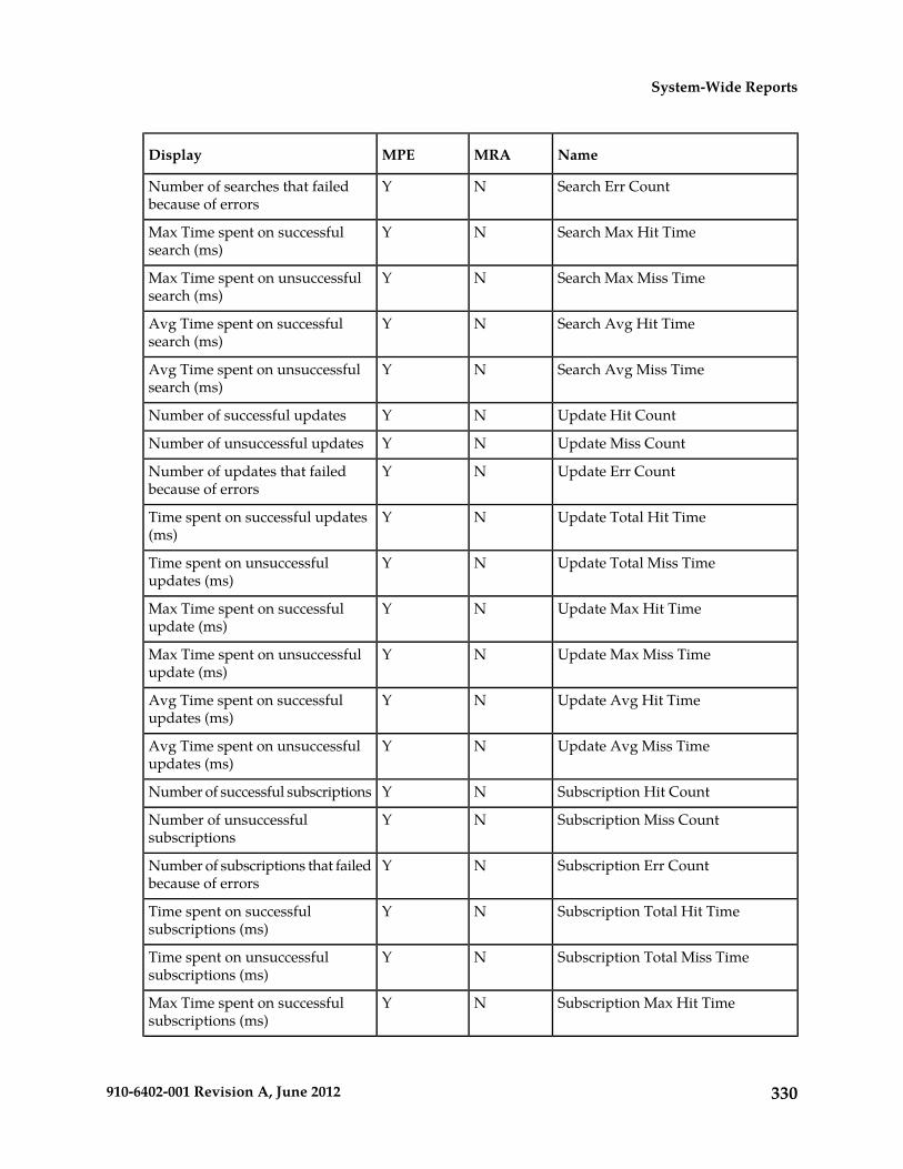
NameMRAMPEDisplay
Search Err CountNYNumber of searches that failedbecause of errors
Search Max Hit TimeNYMax Time spent on successfulsearch (ms)
Search Max Miss TimeNYMax Time spent on unsuccessfulsearch (ms)
Search Avg Hit TimeNYAvg Time spent on successfulsearch (ms)
Search Avg Miss TimeNYAvg Time spent on unsuccessfulsearch (ms)
Update Hit CountNYNumber of successful updates
Update Miss CountNYNumber of unsuccessful updates
Update Err CountNYNumber of updates that failedbecause of errors
Update Total Hit TimeNYTime spent on successful updates(ms)
Update Total Miss TimeNYTime spent on unsuccessfulupdates (ms)
Update Max Hit TimeNYMax Time spent on successfulupdate (ms)
Update Max Miss TimeNYMax Time spent on unsuccessfulupdate (ms)
Update Avg Hit TimeNYAvg Time spent on successfulupdates (ms)
Update Avg Miss TimeNYAvg Time spent on unsuccessfulupdates (ms)
Subscription Hit CountNYNumber of successful subscriptions
Subscription Miss CountNYNumber of unsuccessfulsubscriptions
Subscription Err CountNYNumber of subscriptions that failedbecause of errors
Subscription Total Hit TimeNYTime spent on successfulsubscriptions (ms)
Subscription Total Miss TimeNYTime spent on unsuccessfulsubscriptions (ms)
Subscription Max Hit TimeNYMax Time spent on successfulsubscriptions (ms)
330910-6402-001 Revision A, June 2012
System-Wide Reports

NameMRAMPEDisplay
Subscription Max Miss TimeNYMax Time spent on unsuccessfulsubscriptions (ms)
Subscription Avg Hit TimeNYAvg Time spent on successfulsubscriptions (ms)
Subscription Avg Miss TimeNYAvg Time spent on unsuccessfulsubscriptions (ms)
Unsubscription Hit CountNYNumber of successfulunsubscriptions
Unsubscription Miss CountNYNumber of unsuccessfulunsubscriptions
Unsubscription Err CountNYNumber of unsubscriptions thatfailed because of errors
Unsubscription Total Hit TimeNYTime spent on successfulunsubscriptions (ms)
Unsubscription Total Miss TimeNYTime spent on unsuccessfulunsubscriptions (ms)
Unsubscription Max Hit TimeNYMax Time spent on successfulunsubscriptions (ms)
Unsubscription Max Miss TimeNYMax Time spent on unsuccessfulunsubscriptions (ms)
Unsubscription Avg Hit TimeNYAvg Time spent on successfulunsubscriptions (ms)
Unsubscription Avg Miss TimeNYAvg Time spent on unsuccessfulunsubscriptions (ms)
Color Threshold Configuration
The Color Threshold Configuration popup window is brought up when you click the ChangeThresholds button, located in the top right corner of the KPI Dashboard.
The values displayed in the dialog boxes are the current settings. The user can modify the values andclick Save to put the new values into effect. The values is saved so the next time the dashboard isopened it uses the same values.
Note: Saving the thresholds affects other users that may be viewing the dashboard at the same time.
The Cancel button closes the popup dialog without any changes to the KPI dashboard display. TheReset button restores the values to their defaults. The TPS and session limits for the MRA/MPE willbe set to the officially supported rates for the current software release.
331910-6402-001 Revision A, June 2012
System-Wide Reports

Viewing the Trending Reports
To view the trending reports, from the System Wide Reports section of the navigation pane, selectTrending Reports.
The navigation pane displays the four trending reports. The reports display separate aggregate MPEand MRA statistics in graph tables:
The trending report columns display the following data:
• PDN Connection Count — The number of PDN connections that communicate to the diameternetwork elements.
• Session Count — The number of diameter sessions (for example, Gx or Gy) which are maintainedin the MPE.
• MRA Binding Count — The number of bindings (for example, UE or Policy rules and chargefunction MPE pairs) which are maintained in the MRA.
Note: A binding is the MPA routing information. The UE stores the user identity UE NAI, UE IPaddresses, the selected MPE identity IP-CAN session, and APN if it is available.
• Transaction Per Second — The number of diameter requests and answer pairs processed in asecond.
Viewing the PDN Connection Count
To view the Packet data network (PDN) connection count report, from the System Wide Reportssection of the navigation pane, select PDN Connection Count.
The PDN connection count page is displayed with MRA and Policy server graph tables.
The PDN connection count displays the following:
• View Raw Data — The interval data statistics display in the table.• Export CSV — The interval data statistics are exported and displayed in the graph table.• View Summary — The distribution data of the interval statistics are viewed in the graph table.• Start Date & Time — The start date and time for the event of interest. For example, you must select
the year, month, and day. The established time must be entered manually and will start after theset duration of 24 hours, 7 days, or 30 days.
• Duration — Displays the time duration of the data in a pulldown list. You are provided with thefollowing options:
• 24 hours• 2 days• 3 days• 4 days• 5 days• 6 days• 7 days
Note: The default is 24 hours.
332910-6402-001 Revision A, June 2012
System-Wide Reports

• Show Aggregation — If the box is checked, the aggregated data of all selected Multimedia PolicyEngine (MPEs) or MRAs are displayed in the graph table.
Note: If a MRA or MPE is not selected, then the chart graph does not display.
• Refresh — You are provided with the most recently updated graph table.
Viewing the Session Count
The session counts determine the number of Gx or Gy sessions maintained in the MPE. To view thesession count report, from the System Wide Reports section of the navigation pane, select SessionCount.
The Session Count page is displayed with interval data statistics.
The session count columns display the following:
• View Raw Data — The interval data statistics displayed in the table.• Export CSV — The interval data statistics are exported and displayed in the table.• View Summary — The distribution data of the interval data statistics are viewed in the table.• Start Date & Time — The start date and time for the event of interest. For example, you must select
the year, month, and day. The established time must be entered manually and will start after theset duration of 24 hours, or 2, 3, 4, 5, 6, or 7 days.
• Duration — Displays the time duration of the data in a pulldown list. You are provided with thefollowing options:
• 24 hours• 2 days• 3 days• 4 days• 5 days• 6 days• 7 days
Note: The default is 24 hours.
• Show Aggregation— If the box is checked, the aggregated data of all selected MPE or MRA contentis displayed in the table.
Note: If a MRA or MPE is not selected, then the chart graph does not display.
• Refresh— You are provided with the most recently updated graph table.
Viewing MRA Binding Count
The MRA binding count determines the number of MRA bindings UE or PCRF pairs maintained inthe MRA. To view the MRA binding count report from the System Wide Reports section of thenavigation pane, select MRA Binding Count.
The MRA Binding Count page displays with binding count numbers and dates.
The MRA binding count columns display the following:
• View Raw Data — The interval data statistics displayed in the graph table.• Export CSV — The interval data statistics are exported and displayed in the graph table.
333910-6402-001 Revision A, June 2012
System-Wide Reports

• View Summary — The distribution data of the interval statistics viewed in the graph table.• Start Date & Time — The start date and time for the event of interest. For example, you must select
the year, month, and day. The established time must be entered manually and will start after theset duration of 24 hours, or 2, 3, 4, 5, 6, or 7 days.
• Duration — Displays the time duration of the data in a pulldown list. You are provided with thefollowing options:
• 24 hours• 2 days• 3 days• 4 days• 5 days• 6 days• 7 days
Note: The default is 24 hours.
• Show Aggregation — If the box is checked, the aggregated data of all selected MPE or MRA contentis displayed in the graph table.
• Refresh — You are provided with the most recently updated graph table.
Viewing Transactions Per Second
The transactions per second determines the number of diameter request or diameter answer pairsprocessed in a second. To view the Transactions per second report from the System Wide Reportssection of the navigation pane, select Transactions Per Second.
The Transactions Per Second page displays the Transaction per second MRA and policy server graphtables.
The Transactions per second report columns display the following:
• View Raw Data — The interval data statistics displayed in the graph table.• Export CSV — The interval data statistics are exported and displayed in the graph table.• View Summary — The distribution data of the interval statistics viewed in the graph table.• Start Date & Time — The start date and time for the event of interest. For example, you must select
the year, month, and day. The established time must be entered manually and will start after theset duration of 24 hours, or 2, 3, 4, 5, 6, or 7 days.
• Duration — Displays the time duration of the data in a pulldown list. You are provided with thefollowing options:
• 24 hours• 2 days• 3 days• 4 days• 5 days• 6 days• 7 days
Note: The default is 24 hours.
334910-6402-001 Revision A, June 2012
System-Wide Reports

• Show Aggregation — If the box is checked, the aggregated data of all selected MPE or MRA contentis displayed in the graph table.
• Refresh — You are provided with the most recently updated graph table.
Viewing the Connection Status Report
The connection status report provides an aggregate view of connections maintained by managedPolicy Management systems. The display is refreshed every ten seconds.
To view the connection status report, from the System Wide Reports section of the navigation pane,select Connection Status.
Figure 29: Sample Connection Status Report shows a sample connection status report.
Figure 29: Sample Connection Status Report
The report columns display the following data:
• Server — name of the associated system• Server Type — MPE (Multimedia Policy Engine) or MRA (Multi-Protocol Routing Agent)• Remote Identity — the Diameter ID (if known) or IP address of the remote system• Type — the type of connection• Status — the status of the connection (the possible values are protocol-specific)• Up/Down Since — the timestamp when the connection reached its current state (N/A if the
connection has bever been established)• # Connect — the number of times that the connection has been re-established
Note: This counter is reset if the cluster is restarted.
• Msgs Sent — the number of Diameter or RADIUS protocol messages that have been sent to theremote system
• Msgs Received — the number of protocol messages that have been received from the remote system• Errors Sent — the number of protocol error messages that have been sent to the remote system• Errors Received — the number of protocol error messages that have been received from the remote
system
If a connection is in a non-functional state, the row is displayed in red; if a connection is in a transitionalstate between functional and non-functional (including when a connection is being established), therow is displayed in yellow.
From the report page you can do the following:
335910-6402-001 Revision A, June 2012
System-Wide Reports

• To sort the report on any column, click the column title.• To select connections from an individual Policy Management cluster, select it from the Server list.• To select connections from a class of Policy Management cluster, select All (the default), MRA, or
MPE from the Server Type list.• To select connections from a specific remote identity, select it from the Remote Identity list.• To select connections by connection type, select it from the Type list.• To select connections by connection status, select it from the Status list.• To pause the display of connections, click Pause. To resume the display, click Refresh.• To display another page of the report, click on the page number.• To reformat the report for printing, click Printable Format.• To save the report in comma-separated-value (spreadsheet) format, click Save as CSV.• To save the report as a Portable Document Format file, click Export PDF.
Viewing the Protocol Errors Report
The protocol errors report provides an aggregate view of connection errors, with one row for eachdistinct error code or sub-code. The display is refreshed every ten seconds.
To view the protocol errors report, from the System Wide Reports section of the navigation pane,select Protocol Errors.
The report columns display the following data:
• Server — name of the associated system• Server Type — MPE (Multimedia Policy Engine) or MRA (Multi-Protocol Routing Agent)• Remote Identity — the Diameter ID (if known) or IP address of the remote system• Error — the protocol error• # Received — the number of protocol errors received from the remote system• # Sent — the number of protocol errors sent to the remote system
If a connection is in a non-functional state, the row is displayed in red; if a connection is in a transitionalstate between functional and non-functional (including when a connection is being established), therow is displayed in yellow.
From the report page you can do the following:
• To sort the report on any column, click the column title.• To select errors from an individual Policy Management cluster, select it from the Server list.• To select errors from a class of Policy Management cluster, select All (the default), MRA, or MPE
from the Server Type list.• To select errors from a specific remote identity, select it from the Remote Identity list.• To select errors by error type, select it from the Error list.• To pause the display of errors, click Pause. To resume the display, click Refresh.• To display another page of the report, click on the page number.• To reformat the report for printing, click Printable Format.• To save the report in comma-separated-value (spreadsheet) format, click Save as CSV.• To save the report as a Portable Document Format file, click Export PDF.
336910-6402-001 Revision A, June 2012
System-Wide Reports

Viewing the Policy Statistics Report
The policy statistics report provides an aggregate view of policy statistics, with one row for each policy,allowing an administrator to gauge the performance of individual policies. The display is refreshedevery ten seconds.
To view the policy statistics report, from the System Wide Reports section of the navigation pane,select Policy Statistics Report.
The report columns display the following data:
• Server Name — name of the associated system• Server Type — MPE (Multimedia Policy Engine) or MRA (Multi-Protocol Routing Agent)• Policy Name — the name of each policy defined and active on the displayed server• Evaluated — the number of times the displayed policy was evaluated for the displayed server• Executed — the number of times the displayed policy was executed for the displayed server• Ignored — the number of times the displayed policy was ignored by the displayed server• Total Execution Time (ms) — the total execution time for each policy, in milliseconds• Average Execution Time (ms) — the average amount of time it takes a policy to execute, in
milliseconds• Maximum Execution Time (ms) — the maximum execution time for each policy, in milliseconds
If a connection is in a non-functional state, the row is displayed in red; if a connection is in a transitionalstate between functional and non-functional (including when a connection is being established), therow is displayed in yellow.
From the report page you can do the following:
• To sort the report on any column, click the column title.• To display policy statistics for an individual server, select the server's name from the Server Name
list.• To display statistics for a specific policy, select that policy's name from the Policy Name list.• To pause the display of errors, click Pause. To resume the display, click Refresh.• To change the number of results that appear on the page, click the down arrow for the Display
results per page list and select the desired number.• To display another page of the report, click on the page number.• To reformat the report for printing, click Printable Format.• To save the report in comma-separated-value (spreadsheet) format, click Save as CSV.• To save the report as a Portable Document Format file, click Export PDF.
337910-6402-001 Revision A, June 2012
System-Wide Reports

Chapter
25Upgrade Manager
The Upgrade Manager allows you to perform asoftware upgrade from the GUI. The upgrade
Topics:
• Upgrade Manager Elements.....339 process allows a georedundant site to be upgradedin serial order, so no data is lost and there is nodown time. During the upgrade process, theUpgrade Manager screen displays the upgradestatus. Note that access to this GUI option can beaffected by settings on the role setting page.
For specific steps on performing an upgrade, contactthe Tekelec Customer Care Center.
338910-6402-001 Revision A, June 2012

Upgrade Manager Elements
When System Maintenance is selected from the GUI menu, the Upgrade Manager page appears. Allservers in the topology appear in the server table on this page. Servers display in groups by cluster;clusters can be collapsed or expanded by clicking the [-] or [+] icons in the first column of the table.Server information is updated every ten seconds.
There are three types of elements that appear on the Upgrade Manager GUI page: Pulldown menusto filter the servers that appear, the table of filtered servers, and an Operations button. The followinglist of elements describes all of these elements.
Table 30: Upgrade Manager Elements
DescriptionElement
The table displays the server names of all filteredservers.
Name
Use the Appl Type pulldown menu to filter usingthe application type of server(s) to be upgraded:
Appl Type
CMP, MPE, MRA, or All. The table displays allservers in the selected application type.
The table displays the georedundant site name,if any, that is associated with each server.
Site
Use the IP pulldown menu to filter by specifyingthe IP address of a server. The table displays theserver with the specified IP address(es).
IP
Select state of server(s) to be upgraded: Active,Standby, Out-Of-Service, Force Standby, or All.
Server State
The table displays all servers in the selected state.Server state can appear in different colors,depending on the state displayed.
The table displays the previous release of theserver, if known.
Prev Release
The table displays the current release of the server.Running Release
Use the Replication pulldown menu to filter usingthe replication status of server(s) to be upgraded:
Replication
On, Off, or All. The table displays if replication isturned on or off for each server. Replication canappear in different colors, depending on thereplication state displayed.
Use the Legacy Replication pulldown menu tofilter using the legacy replication status of
Legacy Replication
server(s) to be upgraded: On, Off, or All. The tabledisplays if legacy replication is turned on or offfor each server. Legacy replication can appear in
339910-6402-001 Revision A, June 2012
Upgrade Manager

different colors, depending on the legacyreplication state displayed.
The table displays details of last upgradeperformed on each server.
Upgrade Status
Allows one or more servers to be selected. Usedin conjunction with the Operations button.
<Radio button>
Click to view more server upgrade options for theserver selected using the radio button (last column
Operations
in table). Options are Push Script, Force Standby(or Cancel Force Standby), Turn Off Replication,and Turn On Legacy Replication. As a protectivefeature, when a command is executed, a warningmessage pops up, asking if you are sure you wantto execute this operation (OK or Cancel). WhenOK is clicked, a progress bar displays the statusof the command completion in a pop-up window.
340910-6402-001 Revision A, June 2012
Upgrade Manager

Chapter
26System Administration
System Administration describes functions reservedfor CMP system administrators.
Topics:
• Configuring System Settings.....342Note: Some options are visible only when you arelogged in with administrative rights to the CMP.• Importing to and Exporting from the CMP
Database .....344 However, the Change Password option is availableto all users (viewer, operator, and administrator).• The Manager Report.....346
• The Trace Log.....347• Modifying the Trace Log Configuration.....348• Viewing the Audit Log.....348• Managing Scheduled Tasks.....351• Configuring a Task.....352• User Management.....354• Changing a Password.....363• RADIUS Authentication and Accounting.....363• SANE Authentication.....368• Enabling SANE Authentication on the CMP
System.....369• Creating a Customer User Management System
Profile.....370
341910-6402-001 Revision A, June 2012

Configuring System Settings
Within the CMP you can define the settings that control system behavior.
To define system settings:
1. From the System Administration section of the navigation pane, select System Settings.The System Settings page opens in the work area, displaying the current system settings.
2. On the System Settings page, click Modify.The System Settings page opens.
3. In the Configuration section, define the following:a) Idle Timeout (minutes; 0=never) — The interval of time, in minutes, that a session is kept alive.
The default value is 30 minutes; a value of zero indicates the session remains active indefinitely.b) Account Inactivity Lockout (days; 0=never) — The maximum number of days since the last
successful login after which a user is locked out.If the user fails to log in for the defined number of days, the user is locked out and cannot gainaccess to the system until an administrator resets the account. The default value is 21 days; avalue of zero indicates no limit (the user is never locked out for inactivity).
c) Maximum Concurrent Sessions Per User Account (0=unlimited) — The maximum number oftimes a defined user can be logged in simultaneously. A value of zero indicates no limit.
d) Password Expiration Period (days; 0=never) — The number of days a password can be usedbefore it expires. Enter a value from 7 to 365, or 0 to indicate that the password never expires.
e) Password Expiration Warning Period (days; default=3) — The number of days before apassword expires to begin displaying a window to users after login warning that their passwordis expiring.
f) Admin User Password Expiration — By default, the password for the admin user never expires.If you select this option, the admin user is subject to the same password expiration policies asother users.
g) Block users when password expires — By default, once a password expires, the user mustimmediately change it at the next login.If you select this option, if their password expires, users cannot log in at all. (If you select AdminUser Password Expiration and the admin user’s password expires, the user can still log in butmust immediately select a new password.)
h) EMS Shared Secret— Field provided to support third-party single sign-on architectures.i) Minimum Password Length — The minimum allowable length in characters for a password,
from 6 to 64 characters.The default is six characters.
j) Login Banner Title — The title that displays at the top of the login page. The default is"Welcome." You can enter up to ten characters.
k) Login Banner Text — The text that displays on the login page. You can enter up to 255 characters.l) Allow policy checkpoint and restore (copies; 0=disallow) — The number of checkpoints
allowed in the system. Valid value range is 0 to 10. If set to 0, the Policy Checkpoint/Restoreoption is turned off and is no longer visible under the Policy Management heading on the GUImenu. Default value is 0.
342910-6402-001 Revision A, June 2012
System Administration

4. In the Invalid Login Threshold settings section, define the following:a) Enable — Enables login threshold control.
By default, this feature is enabled; clear the check box to disable this feature.b) Invalid Login Threshold Value (number of failed logins) — Defines the maximum number
of consecutive failed logins after which action is taken.Enter a value from 1 through 500; the default is 3 attempts.
c) Action(s) upon Crossing Threshold — The system action to take if a user reaches the invalidlogin threshold:
• Lock user — prevents users from logging in if they reach the invalid login threshold.• Send event log message — If a user account reaches the threshold, an incident is written to
the trace log, including the username and the IP address (in IPv4 or IPv6 format) from whichthe login attempts were made. The default level is Warning; to change the event level, selecta different level from the list.
5. The Password Strength Settings section lists four character categories: lowercase letters, uppercaseletters, numerals, and non-alphabetic characters. You can specify a password strength policy thatrequires users to create passwords by drawing from these categories:
• Require at least categories below — By default, this setting is 0 (disabled). Select it to requireusers to include password characters from between one to four of the categories.
• Require at least lower-case letter(s) (1-64) — By default, this setting is 0 (disabled). Select it torequire users to include from 1 to 64 lowercase letters in their passwords.
• Require at least upper-case letter(s) (1-64) — By default, this setting is 0 (disabled). Select it torequire users to include from 1 to 64 uppercase letters in their passwords.
• Require at least numeral(s) (1-64) — By default, this setting is 0 (disabled). Select it to requireusers to include from 1 to 64 numerals in their passwords.
• Require at least non-alphabetic character(s) (1-64) — By default, this setting is 0 (disabled).Select it to require users to include from 1 to 64 nonalphabetic characters in their passwords.
• Force users with weak password to change password at their next login — By default, thissetting is 0 (disabled). Select it to require users to conform to a new password policy effectivethe next time they log in.
6. When you finish, click Save (or Cancel to discard your changes).
The system settings are configured.
Figure 30: Sample Password Strength Policy shows an example of settings that establish a passwordstrength policy requiring user passwords to contain at least one uppercase letter, four numerals, andone non-alphabetic character. (A password that would satisfy this policy is P@ssword1024.) Userswhose passwords do not meet these requirements will be forced to change their passwords the nexttime they log in.
343910-6402-001 Revision A, June 2012
System Administration

Figure 30: Sample Password Strength Policy
Importing to and Exporting from the CMP Database
In addition to defining manageable objects manually, you can add them to the CMP database usingthe OSSI XML Interface or by importing them from an XML file. You can also export a list of objectsof various types to an XML output file. Additionally, Custom AVP Definitions can be imported aswell as exported. This section describes the OSSI XML Interface and the XML bulk import and exportprocesses.
Using the OSSI XML Interface
The OSSI XML interface provides access to raw data in the system directly via HTTP. The system datais entered and returned as XML documents in accordance with a defined schema. The schema for theinput XML is provided to specify exactly which attributes of a manageable object are permitted onimport, as well as the formatting for those attributes.
You can also define object groups as part of the XML file and import them within the same file. Groupslet you define a logical organization of objects within the CMP at the time of import. Group structuresinclude not only group attributes, but also relationships between groups, subgroups, and objects.
The OSSI XML interface includes the following:
• Topology Interface — Allows you to query and manage network elements within the system• Operational Measurements (OM) Interface — Allows you to retrieve statistical data from the
system• AVP definitions — Allows you to define, save, and restore 3rd party AVP definitions within the
system• Policy Tables — Allows you to export policy tables, and import them to add, edit, replace or delete
a table
For detailed information, see the document OSSI XML Interface Definition.
344910-6402-001 Revision A, June 2012
System Administration

Importing an XML File to Input Objects
During the import process, object definitions are read one at a time from the user-specified XML file.Each object is then validated and checked against the existing database for collisions (duplications).Collisions are detected based on the object name, which is a unique database key. If the object alreadyexists within the system, the existing object’s attributes are updated (overwritten) by the attributesspecified in the XML file being imported. If the object does not exist within the system, the object iscreated and imported as a new object. A blank element value is replaced with a default or null value,as appropriate.
An XML import is limited to 20,000,000 bytes. If you try to import a file larger than that the importwill fail with a result code of 102 (input stream error).
Tekelec recommends that you export the existing database of objects before starting an importationoperation to ensure that you can recreate the previous state if necessary (see Exporting an XML File).
To use an XML file to input defined objects:
1. From the System Administration section of the navigation pane, select Import/Export.The Import/Export page opens in the work area.
Note: Do not select Policy Import/Export, in the Policy Management; that is a different function.
2. On the Import/Export page, enter the file name of the XML import file, or click Browse and, fromthe standard file open window that appears, locate it.
3. Select the type of import: * (specifies import all types), Network Elements, Tiers, ServingGateway/MCC-MNC Mapping, Traffic Profiles, Retry Profiles, Quotas, Match Lists, Services,Charging Servers, Time Periods, Applications, Monitoring key, Custom AVP Definition, PolicyTable, Roles, Scopes, or Users. * is the default value.If you select Network Elements, additional filtering fields are available to help you manage thevolume of data being imported. You can filter by network element name and Diameter identifier.Each additional field accepts a string that can include the wildcard characters * (to represent anystring) and ? (to represent any character). By default, all elements matching the filter are included.For each field you can select the operators AND, OR, AND NOT, or OR NOT; if you select anoperator, an additional statement field appears. You can specify up to six logical combinations offiltering statements.
Note: The concatenation of all filters is left associative. For example, C1 AND C2 OR C3 equals(C1 AND C2) OR C3. The NOT operator affects the succeeding statement(s); for example, C1 ANDNOT C2 AND C3 equals C1 AND (NOT C2) AND C3.
4. Click Import.Data from the XML file is imported. If the operation takes more than five seconds, a progress barappears.
Following the import, status messages provide the total counts of all successful imports, updates, andfailures. Click Details (the button is below the status messages) to open a window containing detailedwarnings and errors for each object. The error messages contain identifying information for the XMLstructure that caused the error, allowing you to pinpoint and fix problems in the XML file.
For each User element, ensure that Role and Scope data is also defined. Tekelec recommends that thesequence of elements in the XML import file is Network Element, Role, Scope, and then User.
345910-6402-001 Revision A, June 2012
System Administration

If an imported user password does not satisfy the current password rules, the user will have to changepasswords on first login. Password expiration timestamps are imported, so the passwords will expireon the schedule of the CMP system from which they were exported.
When traffic profiles are imported, they are imported regardless of their configured precedence values.The CMP system displays a message reminding you to check the precedence values of the importedtraffic profiles. See Setting the Precedence Range for more information.
Exporting an XML File
The Export feature creates an XML file containing definitions for objects within the CMP, in the sameschema used on import. You can back up data by exporting it to an XML file, and restore it by importingthe same file. The export file can also be transferred to a third-party system. To export an XML file:
1. From the System Administration section of the navigation pane, select Import/Export.The Import/Export page opens in the work area.
Note: Do not select Policy Import/Export, in the Policy Management; that is a different function.
2. Select the type of export: Network Elements (the default),Tiers, Serving Gateway/MCC-MNCMapping, Traffic Profiles, Retry Profiles, Quotas, Match Lists, Charging Servers, Time Periods,Applications, Monitoring key, Custom AVP Definition, Policy Table, Roles, Scopes, or Users.If you select Network Elements, additional filtering fields are available to help you manage thevolume of data being exported. You can filter by network element name and Diameter identifier.Each additional field accepts a string that can include the wildcard characters * (to represent anystring) and ? (to represent any character). By default, all elements matching the filter are included.For each field you can select the operators AND, OR, AND NOT, or OR NOT; if you select anoperator, an additional statement field appears. You can specify up to six logical combinations offiltering statements.
Note: The concatenation of all filters is left associative. For example, C1 AND C2 OR C3 equals(C1 AND C2) OR C3. The NOT operator affects the succeeding statement(s); for example, C1 ANDNOT C2 AND C3 equals C1 AND (NOT C2) AND C3.
3. Click Export.A standard file download window opens, and you are prompted, “Do you want to open or savethis file?”
4. Click Save to save the file (or Cancel to cancel the request).Data exported to an XML file. If the operation takes more than five seconds, a progress bar appears.
The user accounts LIadmin, datacollector, and _policy_server cannot be exported.
User passwords are exported in encrypted text. Password expiration timestamps are retained, so thepasswords will expire on the schedule of the CMP system from which they were exported.
The role LIadmin cannot be exported.
The Manager Report
The Manager Report provides information about the CMP cluster itself. This information is similar tothe Cluster Information Report for MPE and MRA clusters. The display is refreshed every ten seconds.
346910-6402-001 Revision A, June 2012
System Administration

To view the Manager Report, select Reports from the System Administration section of the navigationpane.
The fields that are displayed in the Manager Report section include the following:
• Cluster Name and Designation — The name of the cluster, and also whether it is the primary (P)or secondary (S) site.
• Cluster Mode — The status of the cluster:
• Active: The cluster is managing the Policy Management network.• Standby: The cluster is not currently managing the Policy Management network.
To pause refreshing the display, click Pause. To resume refreshing, click Resume. To reset thedisplay counters, click Reset All Counters.
• Cluster Status — The status of the servers within the cluster:
• On-line: If one server, it is active; if two servers, one is active and one is standby.• Degraded: One server is active, but the other server is not available.• Out-Of-Service: Neither server is active.
Also within the Manager Report is a listing of the servers (blades) contained within the cluster. A
symbol ( ) indicates which server currently has the external connection (the active server). Thereport also lists the following server-specific information:
• Overall — Displays the current topology state (Active, Standby, or Forced-Standby), number ofserver (blade) failures, and total uptime (time providing active or standby GUI service). For thedefinitions of these states, see Server Status.
• Utilization — Displays the percentage utilization of disk (of the /var/camiant filesystem), CPU,and memory.
The Actions buttons let you restart the CMP software on the server or restart the server itself.
The Trace Log
The Trace Log is part of system administration records notifications for management activity on theCMP system. You can configure the severity level of messages written to the Trace Log; for information,see Configuring Log Settings.
To view log information using the Trace Log Viewer:
1. From the System Administration section of the navigation pane, select Trace Log.The Trace Log page opens in the work area.
2. Click View Trace Log.The Trace Log Viewer window opens. While data is being retrieved, the in-progress message“Scanning Trace Logs” appears.
347910-6402-001 Revision A, June 2012
System Administration

Modifying the Trace Log Configuration
To configure the trace log display:
1. From the System Administration section of the navigation pane, select Trace Log.The Trace Log page opens in the work area, displaying the current trace log configuration.
2. On the Trace Log page, click Modify.The Modify Trace Log Settings page opens.
3. Define the settings.For a description of the settings, see Configuring Log Settings.
4. When you finish, click Save (or Cancel to discard your changes).The Modify Trace Log Setting page closes.
The trace log configuration is modified.
Viewing the Audit Log
The CMP lets you track and view configuration changes within the system. Using the audit log, youcan track and monitor each configuration event, affording you better system control. The audit log isstored in the database, so it is backed up and can be restored.
To display the audit log:
1. From the System Administration section of the navigation pane, select Audit Log.The Audit Log page opens in the work area.
2. On the Audit Log page, click Show All.The Audit Log opens. (Figure 31: Audit Log shows an example.)
348910-6402-001 Revision A, June 2012
System Administration

Figure 31: Audit Log
For a detailed description of an item, click the underlined description. The details of the eventdisplay. (Figure 32: Audit Log Details shows an example.)
To filter search results, click Refine Search, located at the bottom of the page. (See Searching forAudit Log Entries.)
Figure 32: Audit Log Details
349910-6402-001 Revision A, June 2012
System Administration

Searching for Audit Log Entries
To search for entries in the Audit Log:
1. From the System Administration section of the navigation pane, select Audit Log.The Audit Log page opens in the work area.
2. On the Audit Log page, click Search.The Audit Log Search Restrictions Page opens.
3. Define the following items, depending on how restrictive you want the audit log search to be:
• From/To — Enter the start and end dates and times for this search.• Action by User Name(s) — Enter the name of the user or users to audit.• Action on Policy Server(s) / MRA(s) — Enter the name of the Policy Management device to
audit.• Audit Log Items to Show — Specifies an item to audit for display (depending on the CMP
mode): Policy Server, Network Element, Network Element Group, Network Element Link,Application, MRA, Policy, Policy Group, Account, Tier, Path, Entitlement, Alert, User, Audit,OM Statistics, Quota, Charging Server, Service, Rating Group, Time Period, MPE Manager,Upgrade Manager, Topology Setting, or Global Configuration Settings. By default you canspecify three items; click More Lines to add an additional item.
• Results Forms — Specifies the number of items per page to display, along with which data todisplay (most recent or oldest items).
4. When you finish, click Search.The Audit Log displays search results.
Exporting or Purging Audit Log Data
You can export the audit log to a text file; the default filename is AuditLogExport.txt.
Exporting DataTo export data from the audit logs:
1. From the System Administration section of the navigation pane, select Audit Log.The Audit Log page opens in the work area.
2. On the Audit Log page, click Export/Purge.The Export and Purge Audit Log Items page opens.
3. In the Items to Export section, select one of the following options:a) Export All Items — Writes all audit log entries.b) Export Through Date — Enter a date in the format mm/dd/yyyy, or click the calendar icon,
located to the right of the field, to select a date from the pop-up window.
4. When you finish, click Export.A standard File Download window opens; you can open or save the export file.
The audit log is exported.
350910-6402-001 Revision A, June 2012
System Administration
Purging DataTo purge data from the audit log:
1. From the System Administration section of the navigation pane, select Audit Log.The Audit Log page opens in the work area.
2. On the Audit Log page, click Export/Purge.The Export and Purge Audit Log Items page opens.
3. In the Items to Purge section, enter a date in the format mm/dd/yyyy, or click the calendar icon,located to the right of the field, to select a date from the pop-up window.
4. When you finish, click Purge.You are prompted: “Click ‘OK’ to purge all audit log items through: mm/dd/yyyy.”
5. Click OK (or Cancel to cancel the request).
The data is purged from the audit log.
Managing Scheduled Tasks
The CMP runs batch jobs to complete certain operations. These tasks are scheduled to run at regularintervals, with some tasks scheduled to run in a certain order. You can change the scheduling of thesetasks to better manage network load or to propagate a network element change to the PolicyManagement devices on demand. You can also abort a running task.
CAUTION: Tekelec strongly recommends that you perform these tasks in the order inwhich they are listed, or serious system problems can occur. Consult Tekelec TechnicalSupport before changing any task’s order.
The tasks include:
• Stats Files Synchronization #1, 2, 3, 4 — Synchronizes stats files to defined remote server. Up tofour synchronization tasks can be defined, and they are scheduled independently. Statistics filesare generated and synchronized to external systems only from the active CMP server. This taskretries when the remote server is unreachable. The default number of retries is three times in eachone minute interval. The maximum number of retries in one minute is five times. If a transfer periodis missed, the next time the remote server is reached any files from the missed transfer periods aretransferred. Remote server information that must be defined before this task runs is: Host Name/IPaddress, Remote repository path, and SSH user login and password.
Note: If access to configuration is restricted to Read-Only, you will not be able to configure thistask.
• Health Checker — Periodically checks the MPE devices to ensure that they are online.• OM Statistics — Periodically retrieves Operational Measurement (OM) statistics from all MPE
devices.
The Operational Measurements XML interface retrieves operational counters from the system. TheOM interface requires that the OM Statistics scheduled task be running on the CMP. This taskcollects the operational counters from the Policy Management devices in the network and records
351910-6402-001 Revision A, June 2012
System Administration

them in the CMP database; the data is then available for query via the OM XML interface. You canconfigure the task to poll at intervals between 5 minutes and 24 hours, with a default value of 15minutes; the system keeps the data available for query for 1 to 30 days, with a default value of 7days. The recommended settings for this task vary depending on the volume of data you arecollecting.
When you request OM statistics, the data for the response is taken from the information that hasbeen collected by this task. You must gather data using the OM Statistics scheduled task if youwant data available for subsequent OM queries.
Most values returned as part of the response are presented as the positive change between the starttime and end time. To calculate a response, you must have a minimum of two recorded valuesavailable; thus you must run the OM Statistics task at least twice in a given time period in orderto provide any data through the OM XML interface. The OSSI XML Interface Definition documentdescribes the OM Interface and the OM Statistics in detail.
• Stats File Generator — Generates stats files by pulling the data from CMP database using OSSIAPI. This task is also responsible for cleaning up the statistics files. If no external system isconfigured in any of the Stats File Synchronization tasks, no stats files are generated. Availablesettings for this task are: Root directory of the local repository, with the default as/var/camiant/stats_export; Stats file retention period, with a default of 72 hours; Stats Type -any stats type can be selected to generate stats, and there is no default value.
• OSSI Distributor Task (optional) — Reads from the database topology and subscriber data thathas entered the CMP using the OSSI Interface.
• Subscriber Distributor — Reads subscriber data from the CMP local database and then distributesit to the appropriate Policy Management devices within the system.
• Wireless License Tracking Collector (optional) — Collects wireless Gx sessions for license tracking.This task, disabled by default, is required for license tracking.
• Wireless License Tracking Session Stats Aggregator — Collects wireless Gx session statistics forlicense tracking.
• Wireless License Tracking Session and Subscriber Stats Aging — Removes old data from thebase and rolled-up session and subscriber statistics tables for wireless license tracking.
Configuring a Task
To configure an individual task:
1. From the System Administration section of the navigation pane, select Scheduled Tasks.The Scheduled Task Administration page opens in the work area.
2. To display details about a task, click on its name; the current settings and status are displayed; forexample:
352910-6402-001 Revision A, June 2012
System Administration

3. The options for this task are as follows:
• Reschedule — Click to reschedule the time that this task is performed on the Policy Managementdevice:
• Schedule by Interval (Next Run Time or Run Interval) — Defines the run interval for the taskto follow.
Valid run intervals are from 0 to 24 hours in 5-minute increments.• Following Another Task — Defines the run time as following the completion of another
scheduled task that you select from the list.• Settings — Number of days to keep data; the default is seven days.• Run Now — Runs the process immediately.
You are prompted: “Click ‘OK’ to run this task now.” Click OK to run the task (or Cancel tocancel the request).
• Disable or Enable — Disables or enables the next scheduled execution of this process.
353910-6402-001 Revision A, June 2012
System Administration

If you click Disable, you are prompted: “Click ‘OK’ to disable this task.” Click OK (or Cancelto cancel the request); the task is disabled and will not run at its next scheduled time, and thebutton changes to Enable.
• Refresh — Refreshes the page.• Cancel — Returns to the previous page.
User Management
The CMP lets you configure the following user attributes:
• Roles — What a user can do within the CMP.• Scopes — Network element groups and Policy Management device groups that provide a context
for a role.• Users — Once you define roles and scopes, you can apply them to user profiles.• RADIUS Authentication — Lets the CMP authenticate users using RADIUS Authentication. These
users must match the RADIUS Server account information before access is permitted.
Configuring Roles
Assigning roles to the various users that access the CMP lets you control who can configure and accesswhat within the CMP. The default roles are:
• Viewer — Permits read-only access to functions associated with Policy Management devicemanagement and configuration. Access is also permitted to limited system administration functions,such as Change Password.
• Operator — Permits full read/write access to all Policy Management device management andconfiguration functions. Access is also permitted to all system administration functions except useradministration.
• Administrator — Permits full read/write access to all functions. You cannot delete the Administratorrole.
Creating a New Role
To create a new role:
1. From the System Administration section of the navigation pane, select User Management.The content tree displays the User Management group.
2. From the content tree, select the Roles group.The Role Administration page opens in the work area, displaying existing roles.
3. On the Role Administration page, click Create Role.The New Role page opens. By default, all privileges are set to Hide (that is, the functions do notappear to users of the role, so access must be explicitly granted) or Read-Only.
4. Enter the following information:a) Name — The desired name for the new roleb) Description/Location (optional) — Free-form text
354910-6402-001 Revision A, June 2012
System Administration

c) Policy Server Privileges — Defines access to the following MPE device management functions(assigning each the privilege Hide, Read-Only, or Read-Write):ConfigurationApplicationMatch ListsQuotasServices & Rating GroupsTraffic ProfilesRetry ProfilesCharging ServerTime PeriodMonitoring KeyAVP DefinitionGlobal Configuration Settings
d) Subscriber Privileges — Defines access to the subscriber functions (assigning the privilegeHide, Read-Only, or Read-Write):EntitlementSubscriber TierQuota Usage
e) SPR Privileges — Defines access to the SPR functions (assigning the privilege Hide, Read-Only,or Read-Write):Subscriber Data
f) Network Privileges — Defines access to the network management Paths function, (assigningthe privilege Hide,Read-Only, or Read-Write):Network Element
g) MRA Privileges — Defines access to the MRA Configuration function, (assigning the privilegeHide, Read-Only, or Read-Write):Configuration
h) Policy Management Privileges — Defines access to the policy management functions:Policy Library (with the privileges Hide, Read-Only, Read and Deploy, or Read, Deploy, andWrite),Template Library (with the privileges Hide, Read-Only, or Read-Write)Policy Table Library (with the privileges Hide, Read-Only, or Read-Write)Policy Import/Export (with the privileges Hide, Read-Only, or Read-Write)
i) Platform Setting Privileges — Defines access to the platform setting functions:Topology Configuration (with the privileges Hide, Read-Only, or Read-Write)Server Operation (with the privileges Hide or Read-Write)
j) Upgrade Manager Privileges — Defines access to software upgrade functions:System Maintenance (with the privileges Hide, Read-Only, or Read-Write)
k) System Administration Privileges — Defines access to system administration functions:XML Import/Export (with the privileges Hide or Show)
355910-6402-001 Revision A, June 2012
System Administration

Operational Measurements (with the privileges Hide or Read-Only)User Management (with the privileges Hide, Read-Only, or Read-Write)Scheduled Tasks (with the privileges Hide or Read-Write)Event Log, Audit Log, & Alerts of Policy Server (with the privileges Hide, Read-Only, orRead-Write)Event Log (with the privileges Hide, Read-Only, or Read-Write)Audit Log (with the privileges Hide, Read-Only, or Read-Write)Audit Log User Info (with the privileges Hide or Show)Push Method for Statistics (with the privileges Read-Only or Read-Write)
Note: This privilege is mainly used for KPI Push in the Scheduled Tasks Administration.
If set to Read-Only, the following fields are displayed for the Stats File Generator setting:
• Name• Description• Last Exit Status• Current State• Last Start Time• Last End Time• Follows Task
Task Settings
• Local Repository— Root directory of the local repository.• Maximum age to keep files (hours)— Stats file retention period. Defaults to 72 hours.• File Format— Any format can be selected. Defaults to XML.• Stats Type— Any stats type can be selected to generate stats. Defaults to No one. If you do
not select a stats type, the task will not run normally.
New tasks are created to synchronize stats files. These tasks will retry if a remote server isunreachable. The following fields are displayed for the Stats Files Synchronization setting:
Remove Server Information
1. Host Name/IP Address2. Password3. Path of Remote Repository
• Retry Limit— You have a limit of 3 tries in 1 minute intervals.
Note: There are a total of 4 synchronized tasks which are supported but cannot be edited.
5. When you finish, click Save (or Cancel to discard your changes).
Privileges are assigned to the role.
Modifying a Role
To modify a role:
1. From the System Administration section of the navigation pane, select User Management.The content tree displays the User Management group.
356910-6402-001 Revision A, June 2012
System Administration

2. From the content tree, select the Roles group.The Role Administration page opens in the work area, displaying existing roles.
3. Select the role to modify.The Role page opens.
4. On the Role page, click Modify.The Modify Role page opens.
5. Modify role information as necessary.See Creating a New Role for a description of the fields contained within this page.
6. When you finish, click Save (or Cancel to discard your changes).
The role is modified.
Deleting a Role
You can delete any role except the Administrator role. You cannot delete a role that is in use.
To delete a role:
1. From the System Administration section of the navigation pane, select User Management.The content tree displays the User Management group.
2. From the content tree, select the Roles group.The Role Administration page opens in the work area, displaying existing roles.
3. Delete the role using one of the following methods:
• From the work area, click the Delete icon located next to the role to delete.• From the content tree, select the role to delete (role information displays in the work area), then
click Delete.
You are prompted: “Are you sure you want to delete this Role?”4. Click OK (or Cancel to cancel the request).
The role’s information is deleted from the CMP.
Creating a New Scope
The CMP lets you configure scopes that contain selections of network element groups and PolicyManagement device groups that provide a context for a role. This lets you control what areas or devicesin a network a user can manage. The default scope, Global, contains all items defined within the CMP.Once you define a scope you can apply it to a user.
To configure a new scope:
1. From the System Administration section of the navigation pane, select User Management.The content tree displays the User Management group.
2. In the content tree, click Scopes.The Scope Administration page opens in the work area, displaying existing scopes. The defaultscope is Global.
3. On the Scope Administration page, click Create Scope.The New Scope page opens.
4. Enter the following information:a) Name — The desired name for the new scope.
357910-6402-001 Revision A, June 2012
System Administration

b) Description/Location (optional) — Free-form text.
5. Select the policy server groups included in this scope.6. Select the network element groups included in this scope.7. Select the MRA groups included in this scope.8. When you finish, click Save to create the scope (or Cancel to discard your changes).
The scope is created.
Modifying a Scope
To modify a scope:
1. From the System Administration section of the navigation pane, select User Management.The content tree displays the User Management group.
2. In the content tree, click Scopes.The Scope Administration page opens in the work area, displaying existing scopes. The defaultscope is Global.
3. On the Scope Administration page, select the scope you want to modify.The scope description opens.
4. Click Modify.The Modify Scope page opens. Creating a New Scope describes the fields on this page.
5. Modify scope information as necessary.6. When you finish, click Save (or Cancel to discard the request).
The scope is modified.
Deleting a Scope
You can delete any scope except Global. To delete a scope:
1. From the System Administration section of the navigation pane, select User Management.The content tree displays the User Management group.
2. From the content tree, click Scopes.The Scope Administration page opens in the work area, displaying existing scopes. (Figure 33:Deleting a Scope shows an example.)
3. Delete the role using one of the following methods:
• From the work area, click the Delete icon, located to the right of the role to delete.• From the content tree, select the role to delete (role information displays in the work area), then
click Delete.
You are prompted: “Are you sure you want to delete this Scope?”4. Click OK (or Cancel to cancel the request).
The scope is deleted.
358910-6402-001 Revision A, June 2012
System Administration

Figure 33: Deleting a Scope
Creating a User Profile
The User Management functions include the tools necessary to create, modify, or delete system userprofiles.
The CMP is configured initially with the following default user profiles and passwords:
• admin/policies (you cannot delete this profile)• operator/policies• viewer/policies
Each default user profile has an associated role assigned to it. The admin user is the only profile thatcannot be deleted or have its username modified. Also, the admin user is the only user who can create,modify, or delete other users. The password assigned to the admin user can be changed. For securityreasons, Tekelec recommends changing this value from its default value as soon as the system isinstalled.
Note: When logging in, the username is not case sensitive; however, the password is case sensitive.
To create a new user profile:
1. Log in to the CMP as admin.2. From the System Administration section of the navigation pane, select User Management.
The content tree displays the User Management group.3. In the content tree, click Users.
The User Administration page opens in the work area, displaying existing users.
Note: The Log Out All Users button is visible only to the admin user.
4. Click Create User.The New User page opens.
5. Define the following attributes:a) Username — Assign a name to the user profile (this value is not case sensitive).
359910-6402-001 Revision A, June 2012
System Administration

b) Description/Location (optional) — Free-form text.c) Password — Assign a password to the user profile.
This value is case sensitive and must contain at least six characters; alphabetic, numeric, andspecial characters are allowed).
d) Confirm Password — Re-enter the password to confirm the value entered above.e) Password Expiration Period(days; 0=never) — The number of days a password can be used
before it expires. (This overrides the system setting.)Enter a value from 7 to 365, or 0 to indicate that the password never expires. The default is thesystem setting.
f) Force to Change Password — If selected, the user must change passwords on next login.g) Role — Select a role from the pulldown list to assign to the user profile.h) Scopes — Select one or more scopes to assign to the user profile.
6. When you finish, click Save (or Cancel to discard your changes).
The user profile is created and stored in the Users group.
Modifying a User Profile
To modify a user profile:
1. Log in to the CMP system as admin.2. From the System Administration section of the navigation pane, select User Management.
The content tree displays the User Management group.3. In the content tree, click Users.
The User Administration page opens in the work area, displaying existing users.4. Select the desired user profile from the content tree.
The profile information page opens.5. Click Modify.
The Modify User page opens. (Figure 34: Modify User Page shows an example.)6. Modify the user profile as desired.
(For field descriptions, see Creating a User Profile.)7. When you finish, click Save (or Cancel to discard your changes).
The user profile is modified.
360910-6402-001 Revision A, June 2012
System Administration

Figure 34: Modify User Page
Deleting a User Profile
You can delete any user profile except admin. To delete a user profile:
1. Log in to the CMP as admin.2. From the System Administration section of the navigation pane, select User Management.
The content tree displays the User Management group.3. In the content tree, click Users.
The User Administration page opens in the work area, displaying existing users; for example:
4. Delete the desired user profile using one of the following methods:
• From the work area, select the delete icon, located to the right of the profile you want to delete.
361910-6402-001 Revision A, June 2012
System Administration

• From the content tree, select the user profile that you want to delete (profile information displaysin the work area), then click Delete.
You are prompted: “Are you sure you want to delete this user?”
5. Click OK to delete the user profile (or Cancel to abandon the request).
The user profile is deleted.
Locking and Unlocking User Accounts
A user is locked out after exceeding the login failure threshold, or if the admin user locks the user out.A locked-out user sees the following message on the login page when attempting to log in: “Youraccount is locked. Please contact the Administrator.”
Note: The admin account cannot lock itself.
Locking an AccountTo lock a user account:
1. Log in to the CMP as admin.2. From the System Administration section of the navigation pane, select User Management.
The content tree displays the User Management group.3. In the content tree, click Users.
The User Administration page opens in the work area, displaying existing users.4. Select the desired user profile from the content tree.
The User Administration page opens.5. Click Lock.
You are prompted: “Are you sure you want to lock out this user?”6. Click OK (or Cancel to cancel the request).
The account is locked. The page displays: “User account locked successfully.” The Lock buttonbecomes an Unlock button. On the User Administration page, the user’s Locked Status changesto “Locked.”
Unlocking an AccountTo unlock a user account:
1. Log in to the CMP as admin.2. From the System Administration section of the navigation pane, select User Management.
The content tree displays the User Management group.3. Select the desired user profile from the content tree.
The User Administration page opens.4. Click Unlock.
You are prompted: “Are you sure you want to unlock this user?”5. Click OK (or Cancel to cancel the request).
The account is unlocked. The page displays: “User account unlocked successfully.” The Unlockbutton becomes a Lock button. On the User Administration page, the user’s Locked Status changesto “Unlocked by Admin.”
362910-6402-001 Revision A, June 2012
System Administration

Changing a Password
The Change Password option lets users change their password. This system administration functionis available to all users.
Note: The admin user can change any user’s password.
If a system administrator has configured your account for password expiration, you will receive awarning when you log in that you will need to change your password.
To change your password:
1. From the System Administration section of the navigation pane, select Change Password.The Change Password page opens. If your account is set up with a password expiration period,the expiration date is displayed.
2. Enter the following information:a) Current Password — The present value of the password.b) New Password — The value of the new password.
This value is case sensitive and must conform to the password strength rules. The passwordcannot contain the user name.
3. When you finish, click Change Password.
Your password is changed.
RADIUS Authentication and Accounting
The CMP supports RADIUS authentication and accounting. You can configure the CMP to operate ina network environment including multiple authentication servers, one authentication server, or noservers. If both primary and secondary authentication servers are defined, the authentication processis as follows:
1. The CMP contacts the primary RADIUS server.If it responds with Accept or Reject, that action is followed.
2. If the primary server does not respond within a specified number of retries or before a timeoutvalue, the CMP contacts the secondary RADIUS server (if defined).If it responds with Accept or Reject, that action is followed.
3. If the secondary server does not respond, the CMP authenticates against its local database (ifenabled).
4. If local authentication is not enabled, authentication fails.5. The user admin is always authenticated locally, regardless of configuration settings.
This process provides a fail-safe mechanism for accessing the CMP system even in the face ofmisconfiguration or network problems that cause the RADIUS servers to become inaccessible.
RADIUS configuration involves three steps:
1. Configuring the RADIUS server to accept authentication (and accounting, if used)
363910-6402-001 Revision A, June 2012
System Administration

2. Associating user roles and scopes on the CMP system3. Configuring the CMP system to work with RADIUS
Configuring the RADIUS Server
The RADIUS server must be configured to authenticate clients and users on the CMP system. Someof the configuration values must be consistent with configuration parameters on the CMP. (The RADIUSadministrator will be aware of the names and locations of the configuration files.)
Defining the CMP as a RADIUS ClientThe client file identifies the systems that use the RADIUS server to authenticate user access. A clientshould be defined as a single device; for example:
client 10.0.10.22 { secret = camiant shortname = MPE5}client 10.0.10.23 { secret = camiant shortname = CMP56}
The best practice is to define IP addresses rather than FQDNs. If no netmask is given, the default is/32. The shared secret (in this example, "camiant") must be both defined on the RADIUS server andentered into the CMP configuration (see Enabling RADIUS on the CMP System). The shortname is usedas an alias.
Defining CMP Users to the RADIUS ServerRADIUS can use either a database or a simple flat file as its repository of user information. The followingexample uses a flat file to demonstrate a minimum user configuration. The users file containsauthentication and configuration information for each user. It begins with the username and theauthentication (password) that is required from the user. The user/password line is followed byindented lines that are attributes to be passed back to the requesting server.
When RADIUS has authenticated a user, it sends back various attributes with the authenticationacceptance message. The CMP system uses these attributes to determine what the user can do. Thebest practice is to use a vendor-specific attribute (VSA) dictionary to define what attributes to sendback to the client. Tekelec provides a VSA dictionary file, dictionary.camiant, in the directory/opt/camiant/install/radius. Figure 35: Tekelec VSA Dictionary For RADIUS shows the contentsof this file. The local RADIUS administrator is responsible for incorporating the Tekelec VSA dictionaryinto the RADIUS server.
========== dictionary.camiant ===================# Camiant Inc VSA's, from RFC 2548# The filename given here should be an absolute path.## Place additional attributes or $INCLUDEs here.
VENDOR Camiant 21274BEGIN-VENDOR CamiantATTRIBUTE Camiant-MI-role 1 stringATTRIBUTE Camiant-SUI-role 2 integerATTRIBUTE Camiant-MI-scope 3 stringVALUE Camiant-SUI-role camiantView 101
364910-6402-001 Revision A, June 2012
System Administration

VALUE Camiant-SUI-role camiantUser 102VALUE Camiant-SUI-role camiantService 104END-VENDOR Camiant======================
Figure 35: Tekelec VSA Dictionary For RADIUS
The Tekelec VSA dictionary specifies three attributes. The attributes Camiant-SUI-role is for accessto the SUI. The valid values for the SUI role, in ascending order of capability, are camiantView,camiantUser, and camiantService. RADIUS authentication for the SUI will not work unless thedictionary.camiant has been included into RADIUS.
The attributes Camiant-MI-role and Camiant-MI-scope are for access to the GUI. The GUI has botha scope and a role associated with a user. The responses sent back from the RADIUS server shouldmatch what is configured in the CMP. The defaults for the GUI role, in ascending order of capability,are Viewer, Operator, and Administrator, but the system administrator can create other roles orremove any role except that of Administrator.
The default GUI scope is Global, and the administrator can create other scopes within the GUI.
Associating Roles and Scopes
The GUI of the CMP assigns two attributes to a user, a role and a scope. Users that authenticate againsta RADIUS server are assigned roles and scopes by matching against the attribute values returned bythe RADIUS server.
It is easiest to provide role and scope values using the Tekelec VSA dictionary, by defining the attributesCamiant-MI-role and Camiant-MI-scope. The flexibility of roles and scopes can be supported byRADIUS if the Tekelec dictionary is integrated.
The following example defines users who have access at different role levels:
Jeff Password == "garbage" Camiant-MI-role = "Administrator", Camiant-MI-scope = "Global"
view Password == "camiant" Class = "Viewer", Camiant-MI-role = "Viewer", Camiant-MI-scope = "Global"
However, if Tekelec VSAs are not included in the RADIUS dictionary, then they cannot be defined inthe user file, and only a Class attribute can be returned on a RADIUS authentication. The GUI can usethe Class attribute for RADIUS authentication.
To accept the Class attribute for GUI login, define a scope and a role that matches what the RADIUSserver returns as the Class attribute. The GUI uses the Class atttribute for both required credentials.For example, consider this user defined in RADIUS:
Dawn Password == "camiant" Class = "Viewer"
Dawn can get access to the GUI if you have defined both a role named Viewer and a scope namedViewer; the GUI matches the one returned value to both of the required credentials.
365910-6402-001 Revision A, June 2012
System Administration
Enabling RADIUS on the CMP System
By default, RADIUS Authentication is disabled in the CMP system. Enabling authentication requiresadmin privileges. The user admin is always authenticated against the local database account; thus,the admin user is best suited to setting up RADIUS authentication (see Creating a User Profile).
Two configuration parameters must match with the configuration that was put on the RADIUS server:
• Source of User Credentials must match up with the user configuration in the RADIUS server, butthis will also depend on what is configured in the next parameter.
• If Action if missing credentials is set to Use following defaults then a user will be authenticatedas long as the password is correct. This user could log in even though the class is not valid:
test Password == "tekelec" Class = "noone"
If Action if missing credentials is set to reject then the configuration of the user will depend on theconfiguration of Source of user credentials.
To enable RADIUS authentication and accounting:
1. Log in to the CMP system as admin.2. From the System Administration section of the navigation pane, select User Management.
The content tree displays the User Management group.3. From the content tree, select External Authentication.
The External Authentication page opens, displaying the current configuration information. Bydefault, external authentication is disabled.
4. Click Modify.The modify page opens.
5. In the Configuration section, select Enable RADIUS Authentication.Additional fields appear (Figure 36: External Authentication Configuration Page).
6. Edit the following fields:a) Enable RADIUS Accounting — Enables RADIUS accounting on the CMP system.
This feature is disabled by default. When enabled, the CMP system sends an Accounting-Startmessage to the accounting server when a user logs in, and an Accounting-Stop message whenthe user logs out. These messages contain a session ID attribute that uniquely identifies the usersession so that it can be matched between Start and Stop.
b) Destination for Accounting Messages — Choose the following from the list:
• Both Primary and Secondary (the default) — Specifies that accounting messages generatedfor each user session are sent to both the primary and (when configured) secondary RADIUSservers.
• Primary (Secondary on error) — Accounting messages are sent only to the primary server,as long as it is reachable. If the primary accounting server is unreachable, messages are sentto the secondary accounting server.
c) NAS IP Address (required) — IP address, in IPv4 or IPv6 format, of the network access server.By default, this is the local host address.
d) Use local authentication — Choose when to use local authentication:
• When RADIUS servers timeout
366910-6402-001 Revision A, June 2012
System Administration

• When both RADIUS servers timeout or reject• Never — Fallback to local authentication is never used (however, the user admin is always
authenticated locally)
e) Source of User Credentials — Choose the following from the list:
• RADIUS Class — The value of the Class attribute returned by the server determines boththe role and scope.
• Camiant VSAs — The value of Camiant VSAs returned by the server determines the roleand scope.
f) Action if Missing Credentials:
• Reject — If you select this option, a user whose login credentials are missing is not loggedin.
• Use following defaults:
1. Default Role — Role assigned if the user credentials are missing or mismatched. Thedefault is Viewer.
2. Default Scope — Scope assigned if the user credentials are missing or mismatched. Thedefault is Global.
7. In the RADIUS Servers section, edit the following fields:a) Primary RADIUS Authentication Server
• Server — FQDN or IP address (in IPv4 or IPv6 format) assigned to the primary authenticationserver.
Note: To disable the primary server, delete its IP address.
• Port — IP port number of the primary server. The default is port 1812.• Timeout (seconds) — How long the CMP system waits for a response from the server. The
default is 3 seconds.• Retries — How many times the CMP system tries to send a message to the server. The default
is 3.• Shared Secret — A password-like string that must match between the CMP system and the
server. If it does not match, the server ignores all messages from the CMP system.
b) Secondary RADIUS Authentication ServerIf configured, the secondary authentication server uses the same fields as the primary server.
c) Primary RADIUS Accounting Server
• Server — FQDN or IP address (in IPv4 or IPv6 format) assigned to the primary accountingserver.
• Port — IP port number of the primary server. The default is port 1813.• Timeout (seconds) — How long the CMP system waits for a response from the server. The
default is 3 seconds.• Retries — How many times the CMP system tries to send a message to the server. The default
is 3.• Shared Secret — A password-like string that must match between the CMP system and the
server. If it does not match, the server ignores all messages from the CMP system.
367910-6402-001 Revision A, June 2012
System Administration

d) Secondary RADIUS Accounting ServerIf configured, the secondary accounting server uses the same fields as the primary server.
8. When you finish, click Save (or Cancel to discard your changes).The window closes.
RADIUS Authentication and Accounting is configured.
Figure 36: External Authentication Configuration Page
SANE Authentication
The CMP system supports Secure Access to Network Elements (SANE) authentication and authorization.You can configure the CMP system to operate in a SANE network environment such that a userelsewhere in the network can gain single-signon access. When the CMP system is configured toauthenticate using SANE, users can log in using a SANE client. (Usage of a SANE client is outside thescope of this document.)
The admin account is treated separately. An admin user enters the CMP URL in any supported browserto log in.
368910-6402-001 Revision A, June 2012
System Administration

The authentication process is as follows:
1. From a SANE client GUI, the user selects the CMP system. A web browser session is launched. Anencrypted SANE authentication artifact is sent to the CMP system through the browser.
2. The CMP system forwards the artifact to a SANE server (the SANE responder).3. If the SANE server verifies the artifact, it returns an assigned role and scope for the user, and the
CMP system allows the user to log in accordingly. Otherwise, the CMP system rejects the loginrequest.
4. The user admin is always authenticated locally, regardless of configuration settings. (That userclicks on the Login link.)
Enabling SANE Authentication on the CMP System
By default, SANE Authentication is disabled in the CMP system. Enabling authentication requiresadmin privileges. The user admin is always authenticated against the local database account; thus,the admin user is best suited to setting up SANE authentication (see Creating a User Profile).
To enable SANE authentication:
1. Log in to the CMP system as admin.2. From the System Administration section of the navigation pane, select User Management.
The content tree displays the User Management group.3. From the content tree, select External Authentication.
The External Authentication page opens, displaying the current configuration information. Bydefault, external authentication is disabled.
4. Click Modify.The modify page opens.
5. In the Configuration section, select Enable SANE Authentication.Additional fields appear.
6. Edit the following fields:a) Artifact Parameter Name — Name of the artifact parameter. Enter an alphanumeric string. The
default is artifact.b) Verification for Account — Choose the following from the list:
• On login only (the default) — The CMP system authenticates the user once, on login. Theuser is considered authenticated until logout.
• On each request — The CMP system authenticates the user on login, and then again foreach HTTP or HTTPS request. If any request is not authenticated, the user is immediatelylogged out.
c) Action if Missing Credentials:
• Reject — If you select this option, a user login is rejected even if the authentication issuccessful.
• Use following defaults — If you select this option, a user with missing credentials is allowedto log in, but the system assigns a default role and scope:
1. Default Role — Default role assigned to the user. The default role is Viewer.
369910-6402-001 Revision A, June 2012
System Administration

2. Default Scope — Default scope assigned to the user. The default scope is Global.
7. In the SANE Servers section, edit the following fields:a) SAML Service Name — Name of the Security Assertion Markup Language service registered
with the UDDI server. Enter an alphanumeric string.b) UDDI Inquiry URL — Universal Description, Discovery and Integration URL, in HTTP or
HTTPS format, for the inquiry.
8. When you finish, click Save (or Cancel to discard your changes).The window closes.
SANE authentication is configured on the CMP.
Creating a Customer User Management System Profile
To support identity management (IDM), the CMP system can accept HTTP or HTTPS connectionrequests from an external Customer User Management system to create, update, query, and deleteuser accounts. Requests and responses consist of XML documents. You must define a user profile forthe external system. The profile is a regular CMP user profile with specific roles and scope.
Assign the profile a role that includes the following privileges:
• Show privilege for XML Import/Export• Read-Write privilege for User Management
For information on creating a user profile, see Creating a User Profile. For more information on the XMLapplication programming interface, see the OSSI XML Interface Definitions Guide.
370910-6402-001 Revision A, June 2012
System Administration

Appendix
ACMP Modes
The functions available in the CMP are determinedby the operating modes and sub-modes selected
Topics:
• The Mode Settings Page.....372 when the software is installed. Functions that canchange include:
• Items on the navigation pane• Tabs on the Policy Server Administration page• Protocols supported• Configuration options• Policy options available in the policy wizard• Reports available
Normally, Tekelec pre-configures servers deliveredto customers. However, if it becomes necessary toreplace a server or reinstall the software in the field,the mode selection screen becomes visible, and youmust reset the operational modes as appropriate foryour environment before you can use the product.
This appendix briefly describes the modes andsub-modes available. For information on settingmodes as part of installation, see the SoftwareInstallation Guide.
CAUTION: CMP modes should onlybe set in consultation with TekelecTechnical Support. Setting modesinappropriately could result in the lossof network element connectivity, policyfunction, OM statistical data, andcluster redundancy.
371910-6402-001 Revision A, June 2012

The Mode Settings Page
When you use a web browser to connect to a CMP system after the software is first installed, the ModeSettings page opens (Figure 37: Mode Settings Page). Select modes, sub-modes, and management options,and then click OK. The browser page closes and you are automatically logged out. When you nextlog in, the CMP system reopens in the selected mode.
Table 31: CMP Modes and Sub-Modes briefly describes each mode and sub-mode.
The management options are as follows:
• Manage Policy Servers — Manage MPE devices• Manage SIP-AM Servers — Manage Session Initiation Protocol Application Manager (SIP-AM)
servers• Manage CD-AM Servers — Manage Content Distribution Network servers• Manage MA Servers — Manage Management Agent servers• Manage Policies — Enable the policy wizard• Manage MRAs — Manage Multi-Protocol Routing Agent servers• Manage SPR Subscriber Data — Manage Subscriber Profile Repository servers• Manage Geo-redundant MPE/MRA — Manage georedundant MPE or MRA servers• Manager is HA (clustered) — Enable High Availability features
372910-6402-001 Revision A, June 2012
CMP Modes

Figure 37: Mode Settings Page
Table 31: CMP Modes and Sub-Modes
DescriptionSub-ModeMode
Enables support of a cable carrier environment. Functions aredescribed in the Configuration Management Platform Cable User'sGuide.
Cable Mode
Supports PacketCableMultiMedia functions.
PCMM
Supports Dynamic Quality ofService functions.
DQOS
Supports Diameter AF functions.Diameter AF
373910-6402-001 Revision A, June 2012
CMP Modes

DescriptionSub-ModeMode
Enables support of a wireless carrier environment. Functions aredescribed in the Configuration Management Platform Wireless User'sGuide.
Wireless Mode
Supports RADIUS-S protocol.RADIUS-S
Supports Diameter 3GPPprotocol.
Diameter 3GPP
Supports Diameter 3GPP2protocol.
Diameter 3GPP2
Supports Policy and ChargingControl functions.
PCC Extensions
Supports a subscriber quotaenvironment using the Diameter
Quotas Gx
Gx protocol. The Gx protocolsupports deep packet inspection(DPI) devices.
Supports a subscriber quotaenvironment using the DiameterGy protocol
Quotas Gy
Supports Lawful Interceptfunctions. Described in the
LI
Configuring Lawful InterceptApplication Note.
Supports the Cisco ServiceControl Engine Gx protocol. If
SCE-Gx
this mode is selected, Diameter3GPP and RADIUS must also beselected, and other Gxsub-modes must not be selected.
Supports the Gx-Lite protocol, asimplified version of 3GPP Gx
Gx-Lite
for use by non-GGSN PCEFvendors that do not have accessto network-level information.
Supports the Cisco Gx protocol.Cisco Gx
Enables support of SMS servers. Functions are described in theConfiguration Management Platform Wireless User’s Guide.
SMS Mode
Supports SMS using SMPPprotocol.
SMPP
Supports SMS using XML.XML
374910-6402-001 Revision A, June 2012
CMP Modes

DescriptionSub-ModeMode
Enables support of subscriber database management. Select onlyone sub-mode. Functions are described in the Subscriber DataManagement documentation.
SPR Mode
Supports subscriber profilefunctions.
Subscriber Profiles
Supports subscriber quotas.Quota
Enables support of a wireline carrier environment. Functions aredescribed in the Configuration Management Platform Wireline User’sGuide.
Wireline Mode
Enables the COPS Application Manager product, which acceptsservice provisioning requests from a Session Border Controller
SPC Mode
over the Common Open Policy Service (COPS) protocol. Functionsare described in the Service Provisioning over COPS ApplicationManager User’s Guide.
Enables support of a Cisco Systems environment.SCE Modes
Supports a network containingService Control Engine (SCE)devices.
SCE
Supports a network containingIntelligent Services Gateway(ISG) devices.
ISG
Supports router automaticprotection switching (APS)functions.
APS
Enables support of RADIUS AAA.RADIUS Mode
375910-6402-001 Revision A, June 2012
CMP Modes

Glossary#
3rd Generation Partnership Project3GPP
3rd Generation Partnership Project2
3GPP2
A
Authentication, Authorization, andAccounting
AAA
Access Point NameAPN
The name identifying a generalpacket radio service (GPRS) bearerservice in a GSM mobile network.See also GSM.
The telecommunications softwarethat is hosted on the platform. A
application
service provided to subscribers to anetwork; for example, voice over IP(VoIP), video on demand (VoD),video conferencing, or gaming.
Attribute-Value PairAVP
The Diameter protocol consists ofa header followed by one or moreattribute-value pairs (AVPs). AnAVP includes a header and is usedto encapsulate protocol-specificdata (e.g., routing information) aswell as authentication,authorization or accountinginformation.
B
Bits per secondbps
C
376910-6402-001 Revision A, June 2012

C
Credit Control AnswerCCA
The Diameter message that isreceived from the prepaid ratingengine to acknowledge a CCRcommand.
Credit Control RequestCCR
A Diameter message to be sent toa prepaid rating engine to requestcredit authorization for an SMS.
An application that calculatesbilling charges for a wirelesssubscriber
charging server
Configuration Management PlatformCMP
A centralized management interfaceto create policies, maintain policylibraries, configure, provision, andmanage multiple distributed MPEpolicy server devices, and deploypolicy rules to MPE devices. TheCMP has a web-based interface.
Central Processing UnitCPU
D
Protocol that provides anAuthentication, Authorization, and
Diameter
Accounting (AAA) framework forapplications such as network accessor IP mobility. Diameter works inboth local and roaming AAAsituations.
Diameter can also be used as asignaling protocol for mobilitymanagement which is typicallyassociated with an IMS or wirelesstype of environment. Diameter is thesuccessor to the RADIUS protocol.The MPE device supports a range of
377910-6402-001 Revision A, June 2012
Glossary

D
Diameter interfaces, including Rx,Gx, Gy, and Ty.
Domain Name SystemDNS
A system for converting Internethost and domain names into IPaddresses.
deep packet inspectionDPI
A form of packet filtering thatexamines the data and/or headerpart of a packet as it passes aninspection point. The MPE deviceuses DPI to recognize the applicationfor establishing QoS or managingquota. See also packet inspection.
Dynamic Quality of ServiceDQoS
A COPS-based protocol that is partof the Packet Cable standards usedto communicate between a CMS anda CMTS for setting up voice calls. AnMPE device can be inserted betweenthese two entities to apply additionalpolicy rules as sessions areestablished.
E
The international publictelecommunication numbering
E.164
plan developed by the InternationalTelecommunication Union.
Electronic Serial NumberESN
A notification of a state change toa FRU. An event can be an alarm
event
or an informational notification.Events can indicate the assertion orclearing of an alarm. In addition,events can indicate a basic state
378910-6402-001 Revision A, June 2012
Glossary

E
change that is informational andnot related to an alarm condition(for example, card inserted).
F
Fully qualified domain nameFQDN
The complete domain name for aspecific computer on the Internet (forexample, www.tekelec.com).
G
Gateway GPRS Support NodeGGSN
An edge router that acts as agateway between a GPRS wirelessdata network and other networks.The MPE supports GGSN nodes asnetwork elements. See also GPRS,PGW, and SGW.
General Packet Radio ServiceGPRS
A mobile data service for users ofGSM mobile phones.
Graphical User InterfaceGUI
The term given to that set of itemsand facilities which provide theuser with a graphic means formanipulating screen data ratherthan being limited to characterbased commands.
The diameter credit control basedinterface between a PCRF and
Gx
PCEF as defined by 3GPP. Theinterface is used to convey sessioninformation from the PCEF to thePCRF, and in reply the PCRFprovides rule information for thePCEF to enforce.
I
379910-6402-001 Revision A, June 2012
Glossary

I
IP Multimedia SubsystemIMS
These are central integrationplatforms for controlling mobilecommunications services, customermanagement and accounting formobile communications servicesbased on IP. The IMS concept issupported by 3GPP and the UMTSForum and is designed to providea wide range of applicationscenarios for individual and groupcommunication
Internet ProtocolIP
IP specifies the format of packets,also called datagrams, and theaddressing scheme. The networklayer for the TCP/IP protocol suitewidely used on Ethernet networks,defined in STD 5, RFC 791. IP is aconnectionless, best-effort packetswitching protocol. It providespacket routing, fragmentation andre-assembly through the data linklayer.
Internet Protocol ConnectivityAccess Network
IP-CAN
Collection of network entities andinterfaces that provide theunderlying IP transport connectivitybetween the user equipment (UE)and the core network or backboneentities. An example IP-CAN isGPRS. An IP-CAN session canincorporate one or more IP-CANbearers.
L
Lightweight Directory AccessProtocol
LDAP
A protocol for providing andreceiving directory information in aTCP/IP network.
380910-6402-001 Revision A, June 2012
Glossary

L
See LDAP.Lightweight Directory AccessProtocol
M
Mobile Country CodeMCC
A three-digit number that uniquelyidentifies a country served bywireless telephone networks. TheMCC is part of the InternationalMobile Subscriber Identity (IMSI)number, which uniquely identifiesa particular subscriber. See alsoMNC, IMSI.
Mobile Network CodeMNC
A number that identifies a mobilephone carrier. Used in combinationwith a Mobile Country Code (MCC)to uniquely identify a mobile phoneoperator/carrier. See also MCC.
Multimedia Policy EngineMPE
A high-performance,high-availability platform foroperators to deliver and managedifferentiated services overhigh-speed data networks. The MPEincludes a protocol-independentpolicy rules engine that providesauthorization for services based onpolicy conditions such as subscriberinformation, applicationinformation, time of day, and edgeresource utilization.
Multi-Protocol Routing AgentMRA
Scales the Policy Managementinfrastructure by distributing thePCRF load across multiple PolicyServer devices.
See MPE.Multimedia Policy Engine
381910-6402-001 Revision A, June 2012
Glossary

N
Network Access IdentifierNAI
The user identity submitted by theclient during networkauthentication.
A physical piece of equipment ora logical (software) entity
network device
connected to a network; forexample, CMTS, video distributionrouter, gateway router, or a link.This may also includesub-components of networkelements (such as an interface) orlower-level devices such as cablemodems or CPEs.
A map of physical equipment orlogical entities in a network.
network topology
O
Operation Support System InterfaceOSSI
An interface to a “back-end” (office)system. The ConfigurationManagement Platform includes anOSSI XML interface.
P
Packet inspection (or shallowpacket inspection) is a form of
packet inspection
packet filtering that checks theheader portion of a packet. See alsodeep packet inspection.
Policy and Charging ControlPCC
Policy and Charging EnforcementFunction
PCEF
Policy and Charging Rules FunctionPCRF
382910-6402-001 Revision A, June 2012
Glossary

P
The ability to dynamically controlaccess, services, network capacity,and charges in a network.
Packet Data NetworkPDN
A digital network technology thatdivides a message into packets fortransmission.
Public Land Mobile NetworkPLMN
See PCRF.policy and charging rules function
An ordered group of policies,organized for ease ofadministration or deployment.
policy group
Q
Quality of ServiceQoS
Control mechanisms that guaranteea certain level of performance to adata flow.
R
Remote Authentication Dial-In UserService
RADIUS
A client/server protocol andassociated software that enablesremote access servers tocommunicate with a central serverto authorize their access to therequested service. The MPE devicefunctions with RADIUS servers toauthenticate messages received fromremote gateways. See also Diameter.
Radio Access TechnologyRAT
Resource RecordRR
383910-6402-001 Revision A, June 2012
Glossary

R
An entry into the DNS database.Depending on their type (e.g. A,SRV, etc.), RRs provide a differentset of parameters that characterize acertain DNS name.
Real-time Transport ControlProtocol
RTCP
Provides out-of-band controlinformation for an RTP flow.
S
Service Control EngineSCE
A deep-packet inspection product.
Subscriber Data ManagementSDM
Any computer that runs TPD.Could be a Rack Mount Server ora Blade Server.
server
A Diameter session between theMPE and an external device (e.g., a
session
Gx, Gxa, Gx-Lite or Rx session).Subscribers can maintain multiplesessions at any given time.
Serving GPRS Support NodeSGSN
Short Message Peer-to-PeerProtocol
SMPP
An open, industry standardprotocol that provides a flexibledata communications interface fortransfer of short message data.
Simple Mail Transfer ProtocolSMTP
384910-6402-001 Revision A, June 2012
Glossary

S
Simple Network ManagementProtocol.
SNMP
An industry-wide standard protocolused for network management. TheSNMP agent maintains datavariables that represent aspects ofthe network. These variables arecalled managed objects and arestored in a management informationbase (MIB). The SNMP protocolarranges managed objects intogroups.
Subscriber Profile RepositorySPR
A logical entity that may be astandalone database or integratedinto an existing subscriber databasesuch as a Home Subscriber Server(HSS). It includes information suchas entitlements, rate plans, etc. ThePCRF and SPR functionality isprovided through an ecosystem ofpartnerships
Secure Socket LayerSSL
See SPR.Subscriber Profile Repository
U
User EquipmentUE
V
Voice Over Internet ProtocolVoIP
Voice communication based on theIP protocol competes with legacyvoice networks, but also with Voiceover Frame Relay and Voice andTelephonie over ATM. Realtimeresponse, which is characterizedby minimizing frame loss andlatency, is vital to voice
385910-6402-001 Revision A, June 2012
Glossary

V
communication. Users are onlyprepared to accept minimal delaysin voice transmissions.
W
Provisioning whitelist.whitelist
X
eXtensible Markup LanguageXML
A version of the StandardGeneralized Markup Language(SGML) that allows Web developersto create customized tags foradditional functionality.
386910-6402-001 Revision A, June 2012
Glossary