Embed Size (px)
Citation preview
Copyright © 2014, Juniper Networks, Inc. 1
RingMaster® SoftwareConfiguration Guide
Release
9.1March 2014 (Release Date)

2 Copyright © 2014, Juniper Networks, Inc.
Juniper Network, Inc.1194 N. Mathilda AvenueSunnyvale, CA 94089USA408-745-2000www.juniper.net
Copyright © 2014, Juniper Networks, Inc. 3
© 2014 Juniper Networks, Inc. All rights reserved.
TrademarksJuniper Networks, the Juniper Networks logo, NetScreen, NetScreen Technologies, the NetScreen logo, NetScreen-Global Pro, ScreenOS, and GigaScreen are registered trademarks of Juniper Networks, Inc. in the United States and other countries.
The following are trademarks of Juniper Networks, Inc.: ERX, ESP, E-series, Instant Virtual Extranet, Internet Processor, J2300, J4300, J6300, J-Protect, J-series, J-Web, JUNOS, JUNOScope, JUNOScript, JUNOSe, M5, M7i, M10, M10i, M20, M40, M40e, M160, M320, M-series, MMD, NetScreen-5GT, NetScreen-5XP, NetScreen-5XT, NetScreen-25, NetScreen-50, NetScreen-204, NetScreen-208, NetScreen-500, NetScreen-5200, NetScreen-5400, NetScreen-IDP 10, NetScreen-IDP 100, NetScreen-IDP 500, NetScreen-Remote Security Client, NetScreen-Remote VPN Client, NetScreen-SA 1000 Series, NetScreen-SA 3000 Series, NetScreen-SA 5000 Series, NetScreen-SA Central Manager, NetScreen Secure Access, NetScreen-SM 3000, NetScreen-Security Manager, NMC-RX, SDX, Stateful Signature, T320, T640, T-series, and TX Matrix. All other trademarks, service marks, registered trademarks, or registered service marks are the property of their respective owners. All specifications are subject to change without notice. Juniper Networks assumes no responsibility for any inaccuracies in this document. Juniper Networks reserves the right to change, modify, transfer, or otherwise revise this publication without notice
DisclaimerAll statements, specifications, recommendations, and technical information are current or planned as of the date of the publication of this document. They are reliable as of the time of this writing and are presented without warranty of any kind, expressed or implied. In an effort to continuously improve the product and add features, Juniper Networks reserves the right to change any specifications contained in this document without prior notice of any kind.
Copyright © 2014, Juniper Networks, Inc. All rights reserved.
Juniper Networks, the Juniper Networks logo, NetScreen, NetScreen Technologies, the NetScreen logo, NetScreen-Global Pro, ScreenOS, and GigaScreen are registered trademarks of Juniper Networks, Inc. in the United States and other countries.
The following are trademarks of Juniper Networks, Inc.: ERX, ESP, E-series, Instant Virtual Extranet, Internet Processor, J2300, J4300, J6300, J-Protect, J-series, J-Web, JUNOS, JUNOScope, JUNOScript, JUNOSe, M5, M7i, M10, M10i, M20, M40, M40e, M160, M320, M-series, MMD, NetScreen-5GT, NetScreen-5XP, NetScreen-5XT, NetScreen-25, NetScreen-50, NetScreen-204, NetScreen-208, NetScreen-500, NetScreen-5200, NetScreen-5400, NetScreen-IDP 10, NetScreen-IDP 100, NetScreen-IDP 500, NetScreen-Remote Security Client, NetScreen-Remote VPN Client, NetScreen-SA 1000 Series, NetScreen-SA 3000 Series, NetScreen-SA 5000 Series, NetScreen-SA Central Manager, NetScreen Secure Access, NetScreen-SM 3000, NetScreen-Security Manager, NMC-RX, SDX, Stateful Signature, T320, T640, T-series, and TX Matrix. All other trademarks, service marks, registered trademarks, or registered service marks are the property of their respective owners. All specifications are subject to change without notice. Juniper Networks assumes no responsibility for any inaccuracies in this document. Juniper Networks reserves the right to change, modify, transfer, or otherwise revise this publication without notice.

4 Copyright © 2014, Juniper Networks, Inc.
Copyright © 2014, Juniper Networks, Inc.
About This Document
This document provides instructions for using the RingMaster graphical user interface (GUI) tool suite to configure and manage basic functions of a wireless LAN (WLAN).
Read the documentation if you are a network administrator responsible for managing wireless LAN controllers (WLCs) and wireless LAN access points (WLAs) in a network.
This document contains the following topics:
RingMaster User Interface
Working with Network Plans
WLC Configuration
System Configuration
Wireless Services Configuration
AAA Configuration
Integrating a WLM1200-SP into RingMaster
Policies Configuration
Verifying Configuration Changes
Adding a Third Party WLA to a Network Plan
DocumentationConsult the following documents to plan, install, and configure a Juniper Networks WLC and WLA.
Planning, Configuration, and Deployment
RingMaster Quick Start Guide— Instructions for installing and configuring RingMaster services.
RingMaster Management Guide— Instructions for managing and monitoring your WLAN using the RingMaster tool suite. Instructions for planning, deploying, and managing the entire WLAN with the RingMaster tool suite. Read this guide to learn how to plan wireless services.
RingMaster Configuration Guide— Instructions for configuring the WLAN with the RingMaster tool suite. Read this guide to learn how to configure wireless services.
RingMaster Planning Guide— Instructions for planning, deploying, and managing the entire WLAN with the RingMaster tool suite. Read this guide to learn how to plan wireless services.
Installation
Juniper Wireless LAN Controller Hardware Installation Guide— Instructions and specifications for installing an WLC.
JuniperMobility System Software Quick Start Guide— Instructions for performing basic setup of secure (802.1X) and guest (WebAAA™) access, and for configuring a Mobility Domain for roaming
Copyright © 2014, Juniper Networks, Inc.
Juniper Indoor Wireless LAN Access Installation Guide— Instructions and specifications for installing an MP access point and connecting it to an WLC.
Juniper Outdoor Wireless LAN Access Installation Guide— Instructions and specifications for installing outdoor access points and connecting to an WLC.
Juniper Regulatory Information— Important safety instructions and compliance information that you must read before installing Juniper Networks products.
Configuration and Management
Juniper Mobility System Software Configuration Guide— Instructions for configuring advanced features through the MSS CLI.
Juniper Mobility System Software Command Reference— Functional and alphabetic reference to all MSS commands supported on WLCs and MPs.
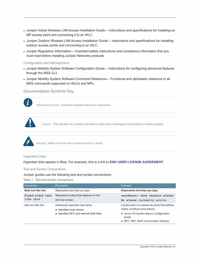
Documentation Symbols Key
Hypertext Links
Hypertext links appear in Blue. For example, this is a link to END USER LICENSE AGREEMENT.
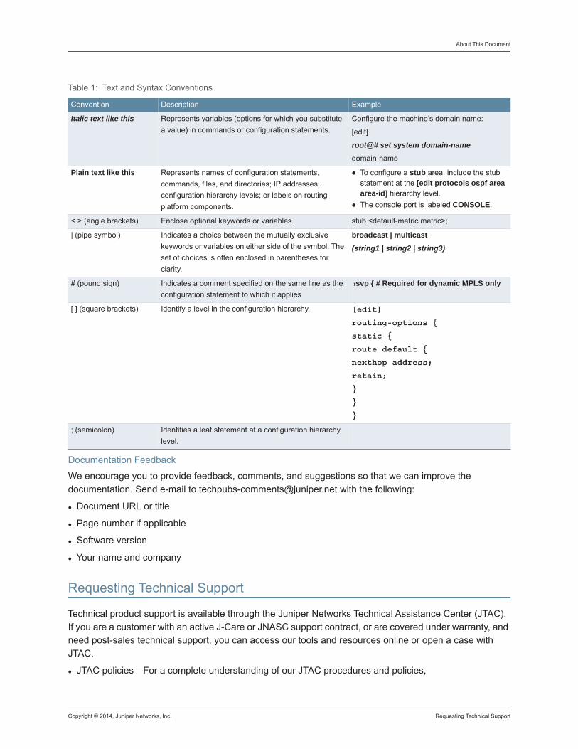
Text and Syntax Conventions
Juniper guides use the following text and syntax conventions:
Informational Note: Indicates important features or instructions.
Caution: This situation or condition can lead to data loss or damage to the product or other property
Warning: Alerts you to the risk of personal injury or death.
Table 1: Text and Syntax Conventions
Convention Description Example
Bold text like this Represents text that you type. Represents text that you type.
Fixed-width text like this
Represents output that appears on the
terminal screen.
user@host> show chassis alarms
No alarms currently active
Italic text like this Introduces important new terms.
Identifies book names.Identifies RFC and Internet draft titles
A policy term is a named structure that defines match conditions and actions.
Junos OS System Basics Configuration GuideRFC 1997, BGP Communities Attribute
Copyright © 2014, Juniper Networks, Inc. Requesting Technical Support
About This Document
Documentation Feedback
We encourage you to provide feedback, comments, and suggestions so that we can improve the documentation. Send e-mail to [email protected] with the following:
Document URL or title
Page number if applicable
Software version
Your name and company
Requesting Technical Support
Technical product support is available through the Juniper Networks Technical Assistance Center (JTAC). If you are a customer with an active J-Care or JNASC support contract, or are covered under warranty, and need post-sales technical support, you can access our tools and resources online or open a case with JTAC.
JTAC policies—For a complete understanding of our JTAC procedures and policies,
Italic text like this Represents variables (options for which you substitute a value) in commands or configuration statements.
Configure the machine’s domain name:
[edit]
root@# set system domain-name
domain-name
Plain text like this Represents names of configuration statements, commands, files, and directories; IP addresses; configuration hierarchy levels; or labels on routing platform components.
To configure a stub area, include the stub statement at the [edit protocols ospf area area-id] hierarchy level.The console port is labeled CONSOLE.
< > (angle brackets) Enclose optional keywords or variables. stub <default-metric metric>;
| (pipe symbol) Indicates a choice between the mutually exclusive keywords or variables on either side of the symbol. The set of choices is often enclosed in parentheses for clarity.
broadcast | multicast
(string1 | string2 | string3)
# (pound sign) Indicates a comment specified on the same line as the configuration statement to which it applies
rsvp { # Required for dynamic MPLS only
[ ] (square brackets) Identify a level in the configuration hierarchy. [edit]
routing-options {
static {
route default {
nexthop address;
retain;
}
}
}
; (semicolon) Identifies a leaf statement at a configuration hierarchy level.
Table 1: Text and Syntax Conventions
Convention Description Example
Requesting Technical Support Copyright © 2014, Juniper Networks, Inc.
Review the JTAC User Guide located at http://www.juniper.net/us/en/local/pdf/resourceguides/ 7100059-en.pdf
Product warranties—For product warranty information, visit http://www.juniper.net/support/warranty/ .
JTAC hours of operation—The JTAC centers have resources available 24 hours a day, 7 days a week, 365 days a year.
Self-Service Online Tools and ResourcesFor quick and easy problem resolution, Juniper Networks has designed an online self-service portal called the Customer Support Center (CSC) that provides you with the following features:
Find CSC offerings: http://www.juniper.net/customers/support/
Search for known bugs: http://www2.juniper.net/kb/
Find product documentation: http://www.juniper.net/techpubs/
Find solutions and answer questions using our Knowledge Base: http://kb.juniper.net/
Download the latest versions of software and review release notes: http://www.juniper.net/customers/csc/software/
Search technical bulletins for relevant hardware and software notifications: https://www.juniper.net/alerts/
Join and participate in the Juniper Networks Community Forum: http://www.juniper.net/company/communities/
Open a case online in the CSC Case Management tool: http://www.juniper.net/cm/
To verify service entitlement by product serial number, use our Serial Number Entitlement (SNE) Tool: https://tools.juniper.net/SerialNumberEntitlementSearch/
Opening a Case with JTACYou can open a case with JTAC on the Web or by telephone.
Use the Case Management tool in the CSC at http://www.juniper.net/cm/ .
Call 1-888-314-JTAC (1-888-314-5822 toll-free in the USA, Canada, and Mexico).
For international or direct-dial options in countries without toll-free numbers, see http://www.juniper.net/support/requesting-support.html .
END USER LICENSE AGREEMENTREAD THIS END USER LICENSE AGREEMENT (“AGREEMENT”) BEFORE DOWNLOADING, INSTALLING, OR USING THE SOFTWARE. BY DOWNLOADING, INSTALLING, OR USING THE SOFTWARE OR OTHERWISE EXPRESSING YOUR AGREEMENT TO THE TERMS CONTAINED HEREIN, YOU (AS CUSTOMER OR IF YOU ARE NOT THE CUSTOMER, AS A REPRESENTATIVE/AGENT AUTHORIZED TO BIND THE CUSTOMER) CONSENT TO BE BOUND BY THIS AGREEMENT. IF YOU DO NOT OR CANNOT AGREE TO THE TERMS CONTAINED HEREIN, THEN (A) DO NOT DOWNLOAD, INSTALL, OR USE THE SOFTWARE, AND (B) YOU MAY CONTACT JUNIPER NETWORKS REGARDING LICENSE TERMS.
Copyright © 2014, Juniper Networks, Inc. Requesting Technical Support
About This Document
1. The Parties. The parties to this Agreement are (i) Juniper Networks, Inc. (if the Customer’s principal office is located in the Americas) or Juniper Networks (Cayman) Limited (if the Customer’s principal office is located outside the Americas) (such applicable entity being referred to herein as “Juniper”), and (ii) the person or organization that originally purchased from Juniper or an authorized Juniper reseller the applicable license(s) for use of the Software (“Customer”) (collectively, the “Parties”).
2. The Software. In this Agreement, “Software” means the program modules and features of the Juniper or Juniper-supplied software, for which Customer has paid the applicable license or support fees to Juniper or an authorized Juniper reseller, or which was embedded by Juniper in equipment which Customer purchased from Juniper or an authorized Juniper reseller. “Software” also includes updates, upgrades and new releases of such software. “Embedded Software” means Software which Juniper has embedded in or loaded onto the Juniper equipment and any updates, upgrades, additions or replacements which are subsequently embedded in or loaded onto the equipment.
3. License Grant. Subject to payment of the applicable fees and the limitations and restrictions set forth herein, Juniper grants to Customer a non-exclusive and non-transferable license, without right to sublicense, to use the Software, in executable form only, subject to the following use restrictions:
a. Customer shall use Embedded Software solely as embedded in, and for execution on, Juniper equipment originally purchased by Customer from Juniper or an authorized Juniper reseller.
b. Customer shall use the Software on a single hardware chassis having a single processing unit, or as many chassis or processing units for which Customer has paid the applicable license fees; provided, however, with respect to the Steel-Belted Radius or Odyssey Access Client software only, Customer shall use such Software on a single computer containing a single physical random access memory space and containing any number of processors. Use of the Steel-Belted Radius or IMS AAA software on multiple computers or virtual machines (e.g., Solaris zones) requires multiple licenses, regardless of whether such computers or virtualizations are physically contained on a single chassis.
c. Product purchase documents, paper or electronic user documentation, and/or the particular licenses purchased by Customer may specify limits to Customer’s use of the Software. Such limits may restrict use to a maximum number of seats, registered endpoints, concurrent users, sessions, calls, connections, subscribers, clusters, nodes, realms, devices, links, ports or transactions, or require the purchase of separate licenses to use particular features, functionality, services, applications, operations, or capabilities, or provide throughput, performance, configuration, bandwidth, interface, processing, temporal, or geographical limits. In addition, such limits may restrict the use of the Software to managing certain kinds of networks or require the Software to be used only in conjunction with other specific Software.Customer’s use of the Software shall be subject to all such limitations and purchase of all applicable licenses.
d. For any trial copy of the Software, Customer’s right to use the Software expires 30 days after download, installation or use of the Software. Customer may operate the Software after the 30-day trial period only if Customer pays for a license to do so. Customer may not extend or create an additional trial period by re-installing the Software after the 30-day trial period.
e. The Global Enterprise Edition of the Steel-Belted Radius software may be used by Customer only to manage access to Customer’s enterprise network. Specifically, service provider customers are expressly prohibited from using the Global Enterprise Edition of the Steel-Belted Radius software to support any commercial network access services.
Requesting Technical Support Copyright © 2014, Juniper Networks, Inc.
The foregoing license is not transferable or assignable by Customer. No license is granted herein to any user who did not originally purchase the applicable license(s) for the Software from Juniper or an authorized Juniper reseller.
4. Use Prohibitions. Notwithstanding the foregoing, the license provided herein does not permit the Customer to, and Customer agrees not to and shall not: (a) modify, unbundle, reverse engineer, or create derivative works based on the Software; (b) make unauthorized copies of the Software (except as necessary for backup purposes); (c) rent, sell, transfer, or grant any rights in and to any copy of the Software, in any form, to any third party; (d) remove any proprietary notices, labels, or marks on or in any copy of the Software or any product in which the Software is embedded; (e) distribute any copy of the Software to any third party, including as may be embedded in Juniper equipment sold in the secondhand market; (f) use any ‘locked’ or key-restricted feature, function, service, application, operation, or capability without first purchasing the applicable license(s) and obtaining a valid key from Juniper, even if such feature, function, service, application, operation, or capability is enabled without a key; (g) distribute any key for the Software provided by Juniper to any third party; (h) use the Software in any manner that extends or is broader than the uses purchased by Customer from Juniper or an authorized Juniper reseller; (i) use Embedded Software on non-Juniper equipment; (j) use Embedded Software (or make it available for use) on Juniper equipment that the Customer did not originally purchase from Juniper or an authorized Juniper reseller; (k) disclose the results of testing or benchmarking of the Software to any third party without the prior written consent of Juniper; or (l) use the Software in any manner other than as expressly provided herein.
5. Audit. Customer shall maintain accurate records as necessary to verify compliance with this Agreement. Upon request by Juniper, Customer shall furnish such records to Juniper and certify its compliance with this Agreement.
6. Confidentiality. The Parties agree that aspects of the Software and associated documentation are the confidential property of Juniper. As such, Customer shall exercise all reasonable commercial efforts to maintain the Software and associated documentation in confidence, which at a minimum includes restricting access to the Software to Customer employees and contractors having a need to use the Software for Customer’s internal business purposes.
7. Ownership. Juniper and Juniper’s licensors, respectively, retain ownership of all right, title, and interest (including copyright) in and to the Software, associated documentation, and all copies of the Software. Nothing in this Agreement constitutes a transfer or conveyance of any right, title, or interest in the Software or associated documentation, or a sale of the Software, associated documentation, or copies of the Software.
8. Warranty, Limitation of Liability, Disclaimer of Warranty. The warranty applicable to the Software shall be as set forth in the warranty statement that accompanies the Software (the “Warranty Statement”). Nothing in this Agreement shall give rise to any obligation to support the Software. Support services may be purchased separately. Any such support shall be governed by a separate, written support services agreement. TO THE MAXIMUM EXTENT PERMITTED BY LAW, JUNIPER SHALL NOT BE LIABLE FOR ANY LOST PROFITS, LOSS OF DATA, OR COSTS OR PROCUREMENT OF SUBSTITUTE GOODS OR SERVICES, OR FOR ANY SPECIAL, INDIRECT, OR CONSEQUENTIAL DAMAGES ARISING OUT OF THIS AGREEMENT, THE SOFTWARE, OR ANY JUNIPER OR JUNIPER-SUPPLIED SOFTWARE. IN NO EVENT SHALL JUNIPER BE LIABLE FOR DAMAGES ARISING FROM UNAUTHORIZED OR IMPROPER USE OF ANY JUNIPER OR
Copyright © 2014, Juniper Networks, Inc. Requesting Technical Support
About This Document
JUNIPER-SUPPLIED SOFTWARE. EXCEPT AS EXPRESSLY PROVIDED IN THE WARRANTY STATEMENT TO THE EXTENT PERMITTED BY LAW, JUNIPER DISCLAIMS ANY AND ALL WARRANTIES IN AND TO THE SOFTWARE (WHETHER EXPRESS, IMPLIED, STATUTORY, OR OTHERWISE), INCLUDING ANY IMPLIED WARRANTY OF MERCHANTABILITY, FITNESS FOR A PARTICULAR PURPOSE, OR NONINFRINGEMENT. IN NO EVENT DOES JUNIPER WARRANT THAT THE SOFTWARE, OR ANY EQUIPMENT OR NETWORK RUNNING THE SOFTWARE, WILL OPERATE WITHOUT ERROR OR INTERRUPTION, OR WILL BE FREE OF VULNERABILITY TO INTRUSION OR ATTACK. In no event shall Juniper’s or its suppliers’ or licensors’ liability to Customer, whether in contract, tort (including negligence), breach of warranty, or otherwise, exceed the price paid by Customer for the Software that gave rise to the claim, or if the Software is embedded in another Juniper product, the price paid by Customer for such other product. Customer acknowledges and agrees that Juniper has set its prices and entered into this Agreement in reliance upon the disclaimers of warranty and the limitations of liability set forth herein, that the same reflect an allocation of risk between the Parties (including the risk that a contract remedy may fail of its essential purpose and cause consequential loss), and that the same form an essential basis of the bargain between the Parties.
9. Termination. Any breach of this Agreement or failure by Customer to pay any applicable fees due shall result in automatic termination of the license granted herein. Upon such termination, Customer shall destroy or return to Juniper all copies of the Software and related documentation in Customer’s possession or control.
10. Taxes. All license fees payable under this agreement are exclusive of tax. Customer shall be responsible for paying Taxes arising from the purchase of the license, or importation or use of the Software. If applicable, valid exemption documentation for each taxing jurisdiction shall be provided to Juniper prior to invoicing, and Customer shall promptly notify Juniper if their exemption is revoked or modified. All payments made by Customer shall be net of any applicable withholding tax. Customer will provide reasonable assistance to Juniper in connection with such withholding taxes by promptly: providing Juniper with valid tax receipts and other required documentation showing Customer’s payment of any withholding taxes; completing appropriate applications that would reduce the amount of withholding tax to be paid; and notifying and assisting Juniper in any audit or tax proceeding related to transactions hereunder. Customer shall comply with all applicable tax laws and regulations, and Customer will promptly pay or reimburse Juniper for all costs and damages related to any liability incurred by Juniper as a result of Customer’s non-compliance or delay with its responsibilities herein. Customer’s obligations under this Section shall survive termination or expiration of this Agreement.
11. Export. Customer agrees to comply with all applicable export laws and restrictions and regulations of any United States and any applicable foreign agency or authority, and not to export or re-export the Software or any direct product thereof in violation of any such restrictions, laws or regulations, or without all necessary approvals. Customer shall be liable for any such violations. The version of the Software supplied to Customer may contain encryption or other capabilities restricting Customer’s ability to export the Software without an export license.
12. Commercial Computer Software. The Software is “commercial computer software” and is provided with restricted rights. Use, duplication, or disclosure by the United States government is subject to restrictions set forth in this Agreement and as provided in DFARS 227.7201 through 227.7202-4, FAR 12.212, FAR 27.405(b)(2), FAR 52.227-19, or FAR 52.227-14(ALT III) as applicable.
Requesting Technical Support Copyright © 2014, Juniper Networks, Inc.
13. Interface Information. To the extent required by applicable law, and at Customer's written request, Juniper shall provide Customer with the interface information needed to achieve interoperability between the Software and another independently created program, on payment of applicable fee, if any. Customer shall observe strict obligations of confidentiality with respect to such information and shall use such information in compliance with any applicable terms and conditions upon which Juniper makes such information available.
14. Third Party Software. Any licensor of Juniper whose software is embedded in the Software and any supplier of Juniper whose products or technology are embedded in (or services are accessed by) the Software shall be a third party beneficiary with respect to this Agreement, and such licensor or vendor shall have the right to enforce this Agreement in its own name as if it were Juniper. In addition, certain third party software may be provided with the Software and is subject to the accompanying license(s), if any, of its respective owner(s). To the extent portions of the Software are distributed under and subject to open source licenses obligating Juniper to make the source code for such portions publicly available (such as the GNU General Public License (“GPL”) or the GNU Library General Public License (“LGPL”)), Juniper will make such source code portions (including Juniper modifications, as appropriate) available upon request for a period of up to three years from the date of distribution. Such request can be made in writing to Juniper Networks, Inc., 1194 N. Mathilda Ave., Sunnyvale, CA 94089, ATTN: General Counsel. You may obtain a copy of the GPL at http://www.gnu.org/licenses/gpl.html, and a copy of the LGPL at http://www.gnu.org/licenses/lgpl.html .
Miscellaneous. This Agreement shall be governed by the laws of the State of California without reference to its conflicts of laws principles. The provisions of the U.N. Convention for the International Sale of Goods shall not apply to this Agreement. For any disputes arising under this Agreement, the Parties hereby consent to the personal and exclusive jurisdiction of, and venue in, the state and federal courts within Santa Clara County, California. This Agreement constitutes the entire and sole agreement between Juniper and the Customer with respect to the Software, and supersedes all prior and contemporaneous agreements relating to the Software, whether oral or written (including any inconsistent terms contained in a purchase order), except that the terms of a separate written agreement executed by an authorized Juniper representative and Customer shall govern to the extent such terms are inconsistent or conflict with terms contained herein. No modification to this Agreement nor any waiver of any rights hereunder shall be effective unless expressly assented to in writing by the party to be charged. If any portion of this Agreement is held invalid, the Parties agree that such invalidity shall not affect the validity of the remainder of this Agreement. This Agreement and associated documentation has been written in the English language, and the Parties agree that the English version will govern. (For Canada: Les parties aux présentés confirment leur volonté que cette convention de même que tous les documents y compris tout avis qui s'y rattaché, soient redigés en langue anglaise. (Translation: The parties confirm that this Agreement and all related documentation is and will be in the English language)).
Copyright © 2014, Juniper Networks, Inc. RingMaster Client Main Window 1
RingMaster User Interface
RingMaster User Interface
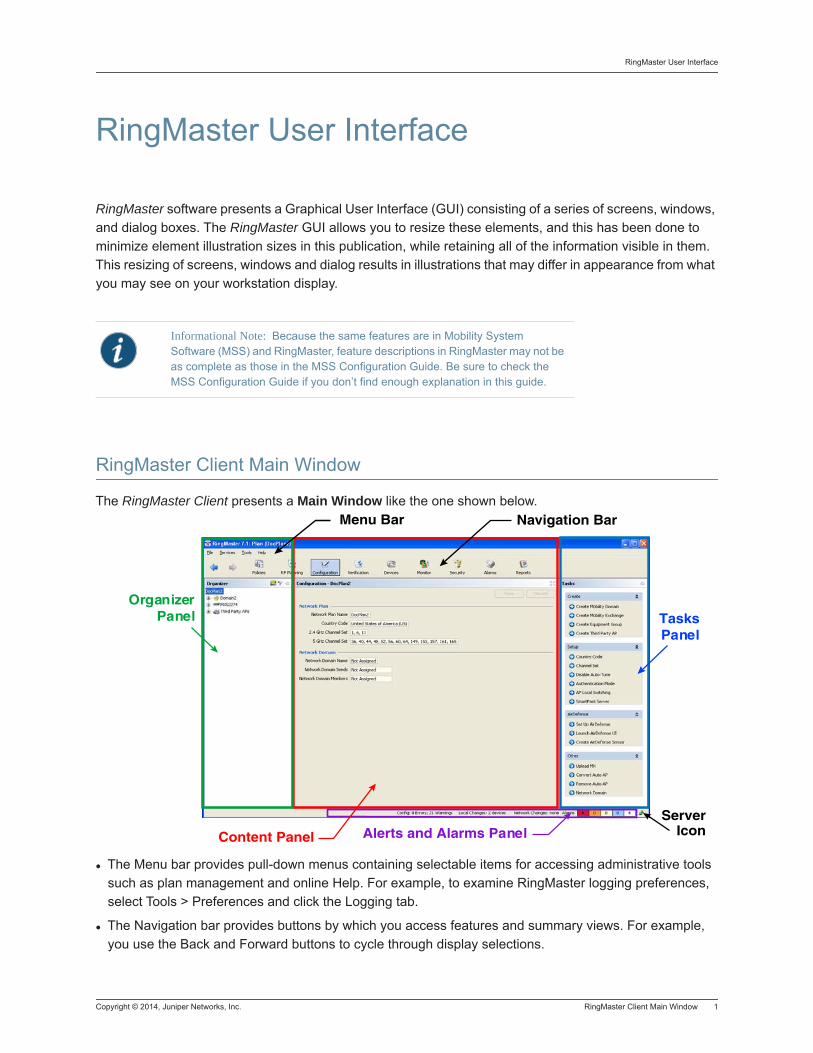
RingMaster software presents a Graphical User Interface (GUI) consisting of a series of screens, windows, and dialog boxes. The RingMaster GUI allows you to resize these elements, and this has been done to minimize element illustration sizes in this publication, while retaining all of the information visible in them. This resizing of screens, windows and dialog results in illustrations that may differ in appearance from what you may see on your workstation display.
RingMaster Client Main Window
The RingMaster Client presents a Main Window like the one shown below.
The Menu bar provides pull-down menus containing selectable items for accessing administrative tools such as plan management and online Help. For example, to examine RingMaster logging preferences, select Tools > Preferences and click the Logging tab.
The Navigation bar provides buttons by which you access features and summary views. For example, you use the Back and Forward buttons to cycle through display selections.
Informational Note: Because the same features are in Mobility System Software (MSS) and RingMaster, feature descriptions in RingMaster may not be as complete as those in the MSS Configuration Guide. Be sure to check the MSS Configuration Guide if you don’t find enough explanation in this guide.
OrganizerPanel Tasks
Panel
Alerts and Alarms Panel Server
IconContent Panel
Menu Bar Navigation Bar
RingMaster User Interface
2 RingMaster Client Main Window Copyright © 2014, Juniper Networks, Inc.
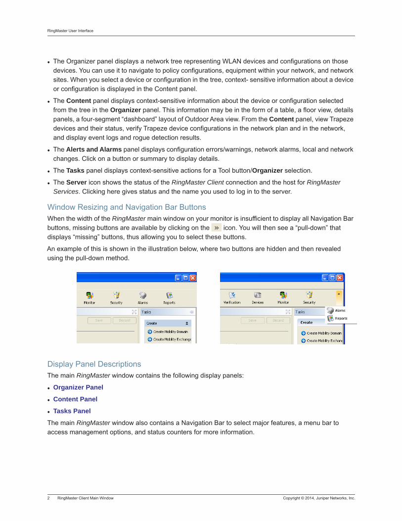
The Organizer panel displays a network tree representing WLAN devices and configurations on those devices. You can use it to navigate to policy configurations, equipment within your network, and network sites. When you select a device or configuration in the tree, context- sensitive information about a device or configuration is displayed in the Content panel.
The Content panel displays context-sensitive information about the device or configuration selected from the tree in the Organizer panel. This information may be in the form of a table, a floor view, details panels, a four-segment “dashboard” layout of Outdoor Area view. From the Content panel, view Trapeze devices and their status, verify Trapeze device configurations in the network plan and in the network, and display event logs and rogue detection results.
The Alerts and Alarms panel displays configuration errors/warnings, network alarms, local and network changes. Click on a button or summary to display details.
The Tasks panel displays context-sensitive actions for a Tool button/Organizer selection.
The Server icon shows the status of the RingMaster Client connection and the host for RingMaster Services. Clicking here gives status and the name you used to log in to the server.
Window Resizing and Navigation Bar ButtonsWhen the width of the RingMaster main window on your monitor is insufficient to display all Navigation Bar buttons, missing buttons are available by clicking on the icon. You will then see a “pull-down” that displays “missing” buttons, thus allowing you to select these buttons.
An example of this is shown in the illustration below, where two buttons are hidden and then revealed using the pull-down method.
Display Panel DescriptionsThe main RingMaster window contains the following display panels:
Organizer Panel
Content Panel
Tasks Panel
The main RingMaster window also contains a Navigation Bar to select major features, a menu bar to access management options, and status counters for more information.
Copyright © 2014, Juniper Networks, Inc. RingMaster Client Main Window 3
RingMaster User Interface
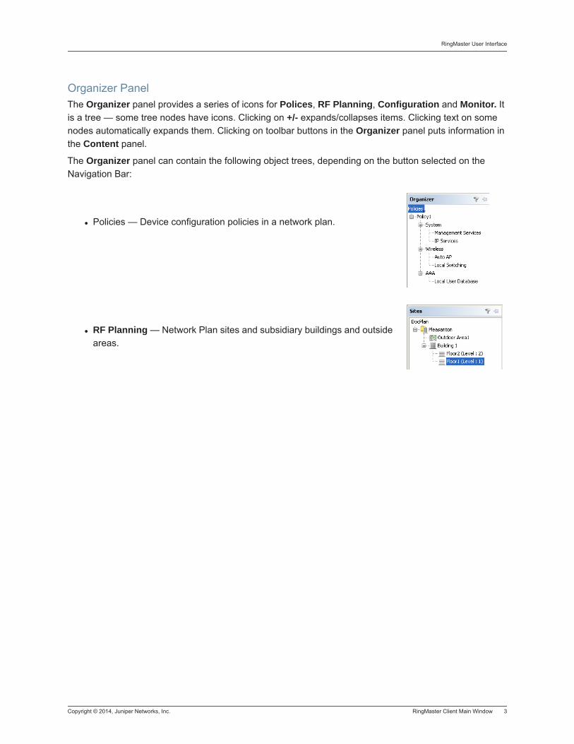
Organizer PanelThe Organizer panel provides a series of icons for Polices, RF Planning, Configuration and Monitor. It is a tree — some tree nodes have icons. Clicking on +/- expands/collapses items. Clicking text on some nodes automatically expands them. Clicking on toolbar buttons in the Organizer panel puts information in the Content panel.
The Organizer panel can contain the following object trees, depending on the button selected on the Navigation Bar:
Policies — Device configuration policies in a network plan.
RF Planning — Network Plan sites and subsidiary buildings and outside areas.
RingMaster User Interface
4 RingMaster Client Main Window Copyright © 2014, Juniper Networks, Inc.
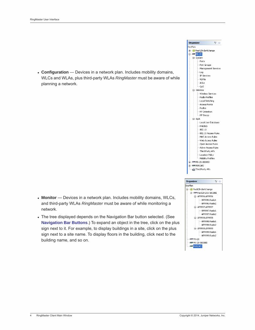
Configuration — Devices in a network plan. Includes mobility domains, WLCs and WLAs, plus third-party WLAs RingMaster must be aware of while planning a network.
Monitor — Devices in a network plan. Includes mobility domains, WLCs, and third-party WLAs RingMaster must be aware of while monitoring a network.
The tree displayed depends on the Navigation Bar button selected. (See Navigation Bar Buttons.) To expand an object in the tree, click on the plus sign next to it. For example, to display buildings in a site, click on the plus sign next to a site name. To display floors in the building, click next to the building name, and so on.
Copyright © 2014, Juniper Networks, Inc. RingMaster Client Main Window 5
RingMaster User Interface
Content Panel
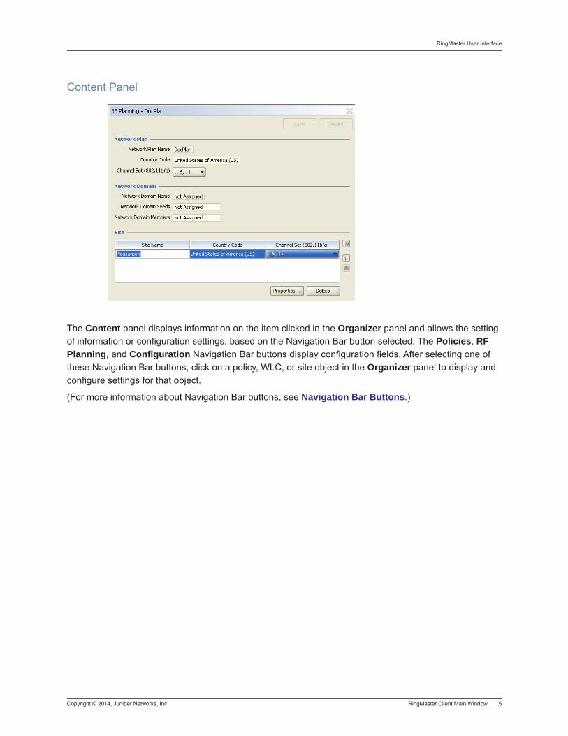
The Content panel displays information on the item clicked in the Organizer panel and allows the setting of information or configuration settings, based on the Navigation Bar button selected. The Policies, RF Planning, and Configuration Navigation Bar buttons display configuration fields. After selecting one of these Navigation Bar buttons, click on a policy, WLC, or site object in the Organizer panel to display and configure settings for that object.
(For more information about Navigation Bar buttons, see Navigation Bar Buttons.)
RingMaster User Interface
6 RingMaster Client Main Window Copyright © 2014, Juniper Networks, Inc.
Tasks Panel
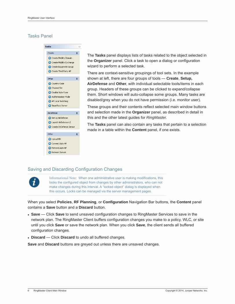
The Tasks panel displays lists of tasks related to the object selected in the Organizer panel. Click a task to open a dialog or configuration wizard to perform a selected task.
There are context-sensitive groupings of tool sets. In the example shown at left, there are four groups of tools — Create, Setup, AirDefense and Other, with individual selectable tools/items in each group. Headers of these groups can be clicked to expand/collapse them. Short windows will auto-collapse some groups. Many tasks are disabled/grey when you do not have permission (i.e. monitor user).
These groups and their contents reflect selected main window buttons and selection made in the Organizer panel, as described in detail in this and the other latest guides for RingMaster.
The Tasks panel can also contain any tasks that pertain to a selection made in a table within the Content panel, if one exists.
Saving and Discarding Configuration Changes
When you select Policies, RF Planning, or Configuration Navigation Bar buttons, the Content panel contains a Save button and a Discard button.
Save — Click Save to send unsaved configuration changes to RingMaster Services to save in the network plan. The RingMaster Client buffers configuration changes you make to a policy, WLC, or site until you click Save or save the network plan. When you click Save, the client sends all buffered configuration changes.
Discard — Click Discard to undo all buffered changes.
Save and Discard buttons are greyed out unless there are unsaved changes.
Informational Note: When one administrative user is making modifications, this locks the configured object from changes by other administrators, who can not make changes during this interval. A “locked object” dialog is displayed when this occurs. Locks can be managed via the server management pages.
Copyright © 2014, Juniper Networks, Inc. RingMaster Client Main Window 7
RingMaster User Interface
Configuration wizards have a Finish or OK button, which saves configuration items you type or select in a wizard. When you save changes in a wizard by clicking Finish or OK, Save and Discard in the Content panel may remain greyed out because there are no unsaved changes to save or discard. When you click a button to open a configuration wizard, and then there are unsaved changes, RingMaster prompts you to apply or cancel changes. Click Apply to save buffered changes. Save, Apply, Finish, and OK do not send configuration changes to WLCs in a network until you deploy changes. (See Reviewing and Deploying WLC Configuration Changes.)
Reviewing and Deploying WLC Configuration ChangesRingMaster does not automatically deploy WLC configuration changes from a network plan to the WLCs in a network. Tasks panel icons allow you to review and deploy changes as follows:
Review — Displays a categorized list of un-deployed changes.
Deploy — Sends changes to a network.
When you click Deploy, RingMaster verifies configuration changes and displays warnings or errors if applicable. If errors are listed, RingMaster does not deploy changes. To resolve errors and deploy changes, use the Verification button to get detailed information on errors and warnings to resolve them. Generally, errors are not meant to be ignored; they are serious configuration problems. Warnings, however, can be safely ignored but should be cleared.
Display Panel Viewing Options
In the Header/title areas of the Organizer, Content and Tasks panels are icons that allow you to alter the “look” of the main window in order to focus on specific areas of this window.
Organizer Panel Icons
There are two icons to the right of the title of this panel — the Tree Filter icon and the Minimize icon.
RingMaster User Interface
8 RingMaster Client Main Window Copyright © 2014, Juniper Networks, Inc.
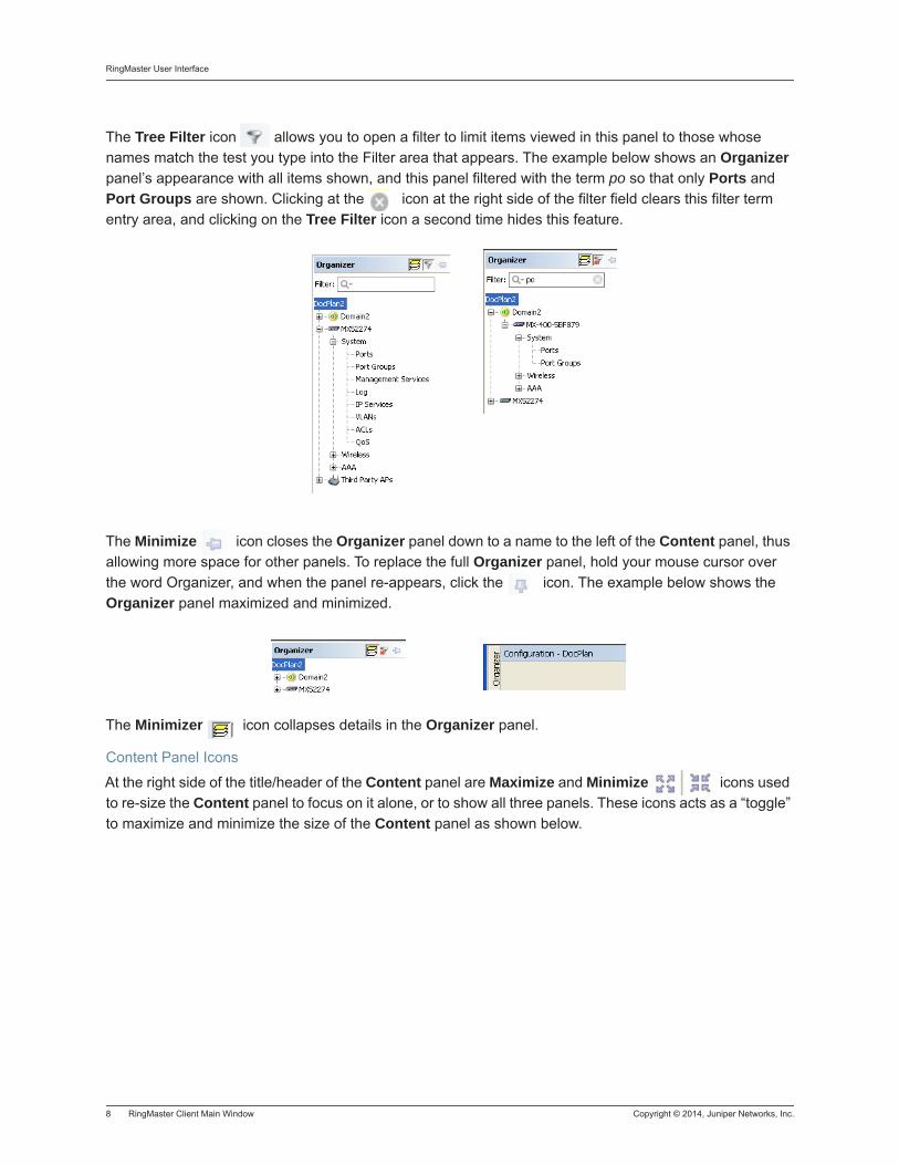
The Tree Filter icon allows you to open a filter to limit items viewed in this panel to those whose names match the test you type into the Filter area that appears. The example below shows an Organizer panel’s appearance with all items shown, and this panel filtered with the term po so that only Ports and Port Groups are shown. Clicking at the icon at the right side of the filter field clears this filter term entry area, and clicking on the Tree Filter icon a second time hides this feature.
The Minimize icon closes the Organizer panel down to a name to the left of the Content panel, thus allowing more space for other panels. To replace the full Organizer panel, hold your mouse cursor over the word Organizer, and when the panel re-appears, click the icon. The example below shows the Organizer panel maximized and minimized.
The Minimizer icon collapses details in the Organizer panel.
Content Panel Icons
At the right side of the title/header of the Content panel are Maximize and Minimize icons used to re-size the Content panel to focus on it alone, or to show all three panels. These icons acts as a “toggle” to maximize and minimize the size of the Content panel as shown below.
Copyright © 2014, Juniper Networks, Inc. RingMaster Client Main Window 9
RingMaster User Interface
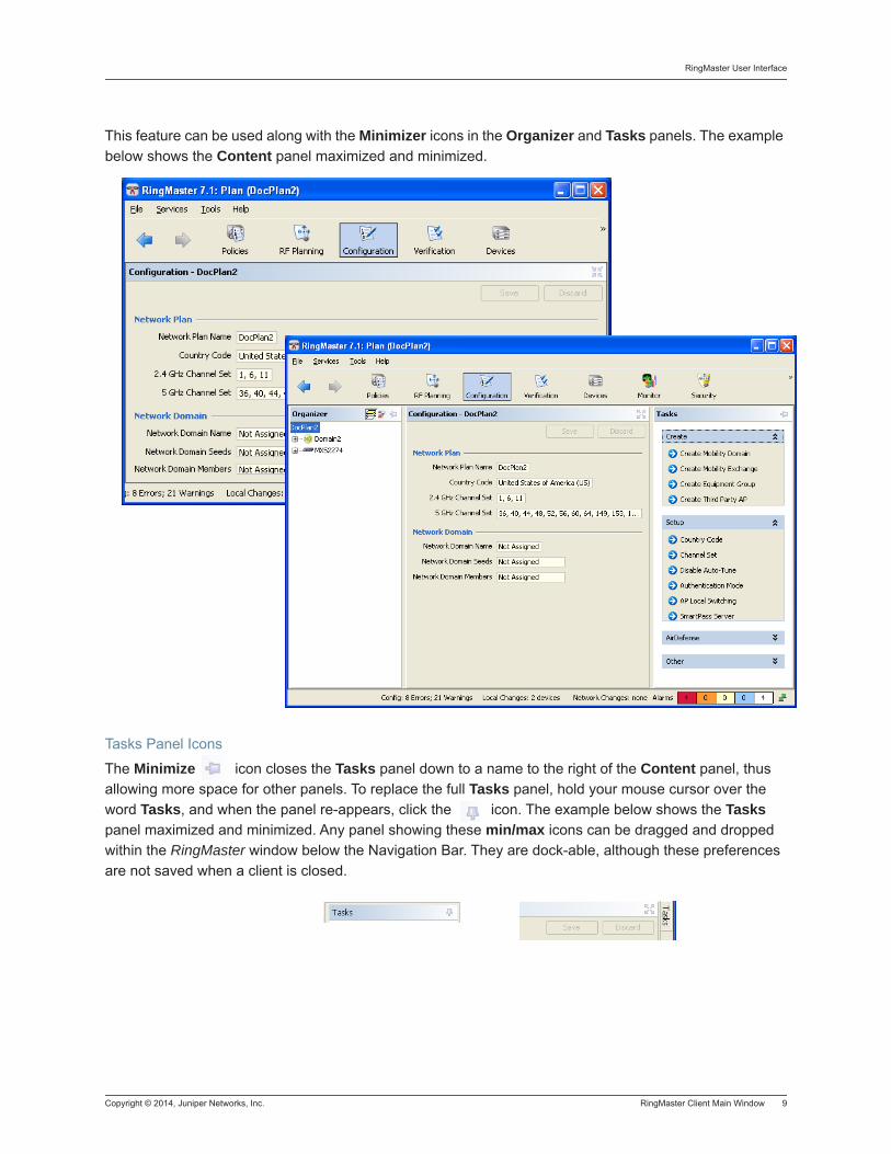
This feature can be used along with the Minimizer icons in the Organizer and Tasks panels. The example below shows the Content panel maximized and minimized.
Tasks Panel Icons
The Minimize icon closes the Tasks panel down to a name to the right of the Content panel, thus allowing more space for other panels. To replace the full Tasks panel, hold your mouse cursor over the word Tasks, and when the panel re-appears, click the icon. The example below shows the Tasks panel maximized and minimized. Any panel showing these min/max icons can be dragged and dropped within the RingMaster window below the Navigation Bar. They are dock-able, although these preferences are not saved when a client is closed.
RingMaster User Interface
10 RingMaster Client Main Window Copyright © 2014, Juniper Networks, Inc.
Resizing a Display Panel
Click and drag the panel border or click the resize icons (where applicable) to resize a panel. The resize icons listed in the table below are supported for panels displayed by the RF Planning, Configuration, and Monitor Navigation Bar buttons.
Configuration Wizards
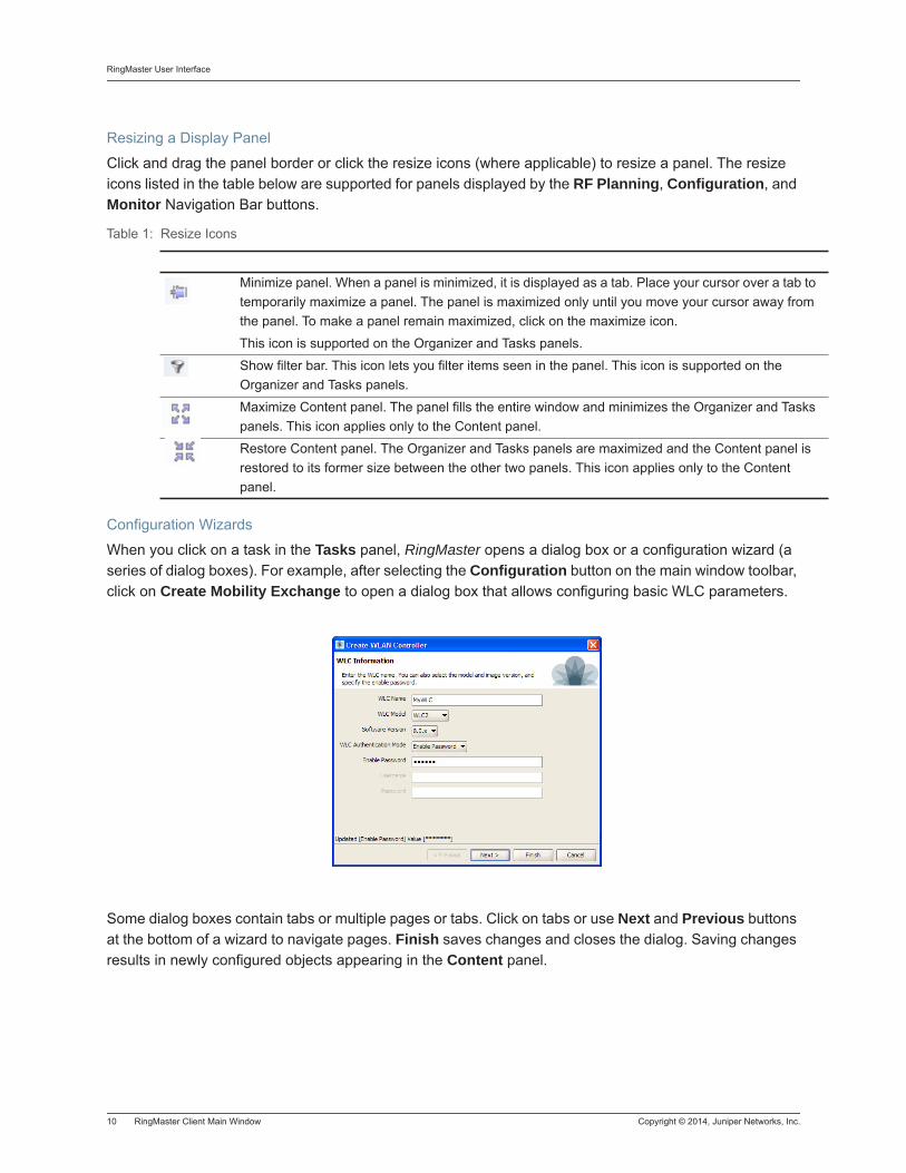
When you click on a task in the Tasks panel, RingMaster opens a dialog box or a configuration wizard (a series of dialog boxes). For example, after selecting the Configuration button on the main window toolbar, click on Create Mobility Exchange to open a dialog box that allows configuring basic WLC parameters.
Some dialog boxes contain tabs or multiple pages or tabs. Click on tabs or use Next and Previous buttons at the bottom of a wizard to navigate pages. Finish saves changes and closes the dialog. Saving changes results in newly configured objects appearing in the Content panel.
Table 1: Resize Icons
icon Description
Minimize panel. When a panel is minimized, it is displayed as a tab. Place your cursor over a tab to temporarily maximize a panel. The panel is maximized only until you move your cursor away from the panel. To make a panel remain maximized, click on the maximize icon.
This icon is supported on the Organizer and Tasks panels.
Show filter bar. This icon lets you filter items seen in the panel. This icon is supported on the Organizer and Tasks panels.
Maximize Content panel. The panel fills the entire window and minimizes the Organizer and Tasks panels. This icon applies only to the Content panel.
Restore Content panel. The Organizer and Tasks panels are maximized and the Content panel is restored to its former size between the other two panels. This icon applies only to the Content panel.
Copyright © 2014, Juniper Networks, Inc. RingMaster Client Main Window 11
RingMaster User Interface
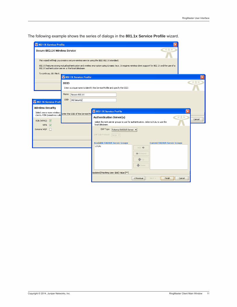
The following example shows the series of dialogs in the 801.1x Service Profile wizard.
RingMaster User Interface
12 RingMaster Client Main Window Copyright © 2014, Juniper Networks, Inc.
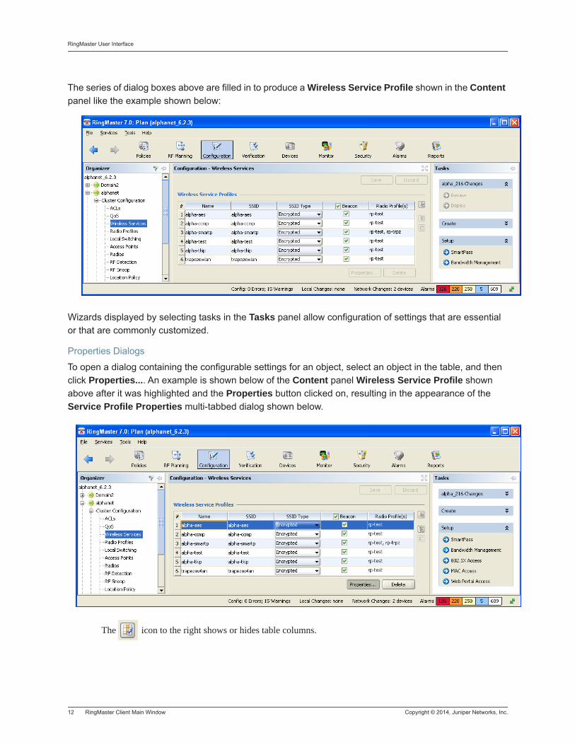
The series of dialog boxes above are filled in to produce a Wireless Service Profile shown in the Content panel like the example shown below:
Wizards displayed by selecting tasks in the Tasks panel allow configuration of settings that are essential or that are commonly customized.
Properties Dialogs
To open a dialog containing the configurable settings for an object, select an object in the table, and then click Properties.... An example is shown below of the Content panel Wireless Service Profile shown above after it was highlighted and the Properties button clicked on, resulting in the appearance of the Service Profile Properties multi-tabbed dialog shown below.
The icon to the right shows or hides table columns.
Copyright © 2014, Juniper Networks, Inc. RingMaster Client Main Window 13
RingMaster User Interface
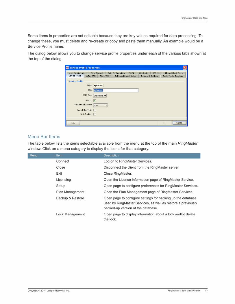
Some items in properties are not editable because they are key values required for data processing. To change these, you must delete and re-create or copy and paste them manually. An example would be a Service Profile name.
The dialog below allows you to change service profile properties under each of the various tabs shown at the top of the dialog.
Menu Bar ItemsThe table below lists the items selectable available from the menu at the top of the main RingMaster window. Click on a menu category to display the icons for that category.
Menu Item Description
File
Connect Log on to RingMaster Services.
Close Disconnect the client from the RingMaster server.
Exit Close RingMaster.
Services
Licensing Open the License Information page of RingMaster Service.
Setup Open page to configure preferences for RingMaster Services.
Plan Management Open the Plan Management page of RingMaster Services.
Backup & Restore Open page to configure settings for backing up the database used by RingMaster Services, as well as restore a previously backed-up version of the database.
Lock Management Open page to display information about a lock and/or delete the lock.
RingMaster User Interface
14 RingMaster Client Main Window Copyright © 2014, Juniper Networks, Inc.
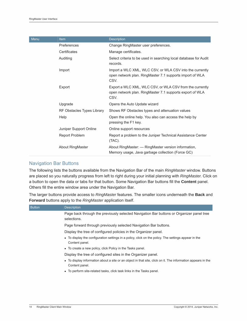
Navigation Bar ButtonsThe following lists the buttons available from the Navigation Bar of the main RingMaster window. Buttons are placed so you naturally progress from left to right during your initial planning with RingMaster. Click on a button to open the data or tabs for that button. Some Navigation Bar buttons fill the Content panel. Others fill the entire window area under the Navigation Bar.
The larger buttons provide access to RingMaster features. The smaller icons underneath the Back and Forward buttons apply to the RingMaster application itself.
Tools
Preferences Change RingMaster user preferences.
Certificates Manage certificates.
Auditing Select criteria to be used in searching local database for Audit records.
Import Import a WLC XML, WLC CSV, or WLA CSV into the currently open network plan. RingMaster 7.1 supports import of WLA CSV.
Export Export a WLC XML, WLC CSV, or WLA CSV from the currently open network plan. RingMaster 7.1 supports export of WLA CSV.
Upgrade Opens the Auto Update wizard
RF Obstacles Types Library Shows RF Obstacles types and attenuation values
Help
Help Open the online help. You also can access the help by pressing the F1 key.
Juniper Support Online Online support resources
Report Problem Report a problem to the Juniper Technical Assistance Center (TAC).
About RingMaster About RingMaster: — RingMaster version information, Memory usage, Java garbage collection (Force GC)
Button Description
Back
Page back through the previously selected Navigation Bar buttons or Organizer panel tree selections.
Forward Page forward through previously selected Navigation Bar buttons.
Policies
Display the tree of configured policies in the Organizer panel. To display the configuration settings in a policy, click on the policy. The settings appear in the Content panel.
To create a new policy, click Policy in the Tasks panel.
RF Planning
Display the tree of configured sites in the Organizer panel. To display information about a site or an object in that site, click on it. The information appears in the Content panel.
To perform site-related tasks, click task links in the Tasks panel.
Menu Item Description
Copyright © 2014, Juniper Networks, Inc. RingMaster Client Main Window 15
RingMaster User Interface
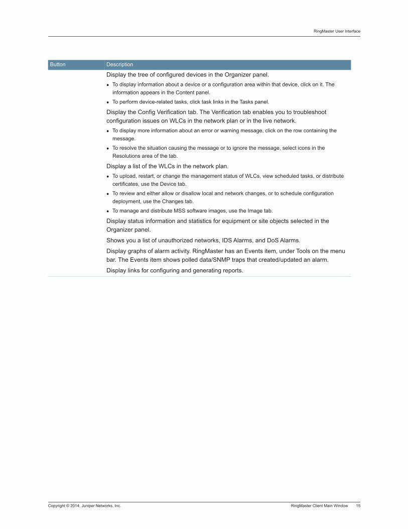
Configuration
Display the tree of configured devices in the Organizer panel. To display information about a device or a configuration area within that device, click on it. The information appears in the Content panel.
To perform device-related tasks, click task links in the Tasks panel.
Verification
Display the Config Verification tab. The Verification tab enables you to troubleshoot configuration issues on WLCs in the network plan or in the live network.
To display more information about an error or warning message, click on the row containing the message.
To resolve the situation causing the message or to ignore the message, select icons in the Resolutions area of the tab.
Devices
Display a list of the WLCs in the network plan. To upload, restart, or change the management status of WLCs, view scheduled tasks, or distribute certificates, use the Device tab.
To review and either allow or disallow local and network changes, or to schedule configuration deployment, use the Changes tab.
To manage and distribute MSS software images, use the Image tab.
Monitor
Display status information and statistics for equipment or site objects selected in the Organizer panel.
Security Shows you a list of unauthorized networks, IDS Alarms, and DoS Alarms.
Alarms
Display graphs of alarm activity. RingMaster has an Events item, under Tools on the menu bar. The Events item shows polled data/SNMP traps that created/updated an alarm.
Reports Display links for configuring and generating reports.
Button Description
RingMaster User Interface
16 RingMaster Client Main Window Copyright © 2014, Juniper Networks, Inc.
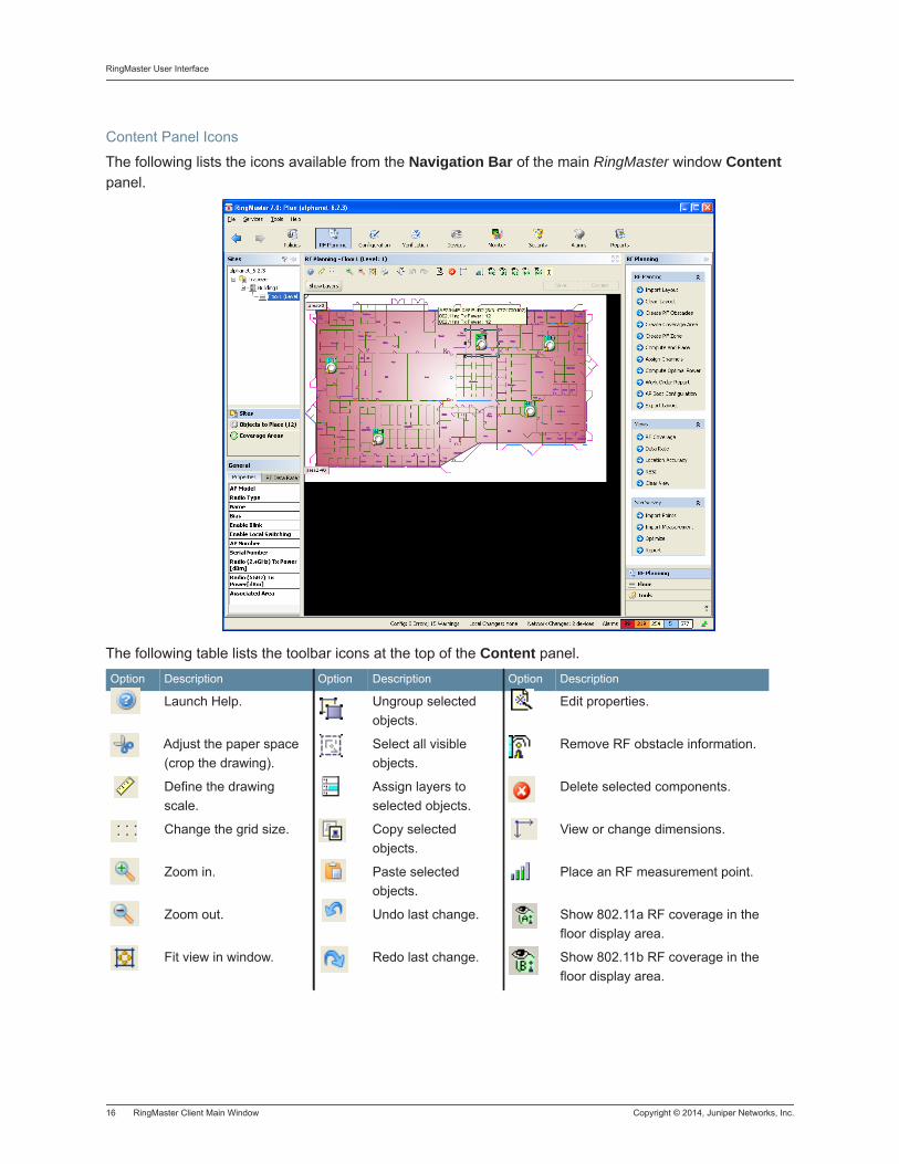
Content Panel Icons
The following lists the icons available from the Navigation Bar of the main RingMaster window Content panel.
The following table lists the toolbar icons at the top of the Content panel.
Option Description Option Description Option Description
Launch Help. Ungroup selected objects.
Edit properties.
Adjust the paper space (crop the drawing).
Select all visible objects.
Remove RF obstacle information.
Define the drawing scale.
Assign layers to selected objects.
Delete selected components.
Change the grid size. Copy selected objects.
View or change dimensions.
Zoom in. Paste selected objects.
Place an RF measurement point.
Zoom out. Undo last change. Show 802.11a RF coverage in the floor display area.
Fit view in window. Redo last change. Show 802.11b RF coverage in the floor display area.
Copyright © 2014, Juniper Networks, Inc. Copying, Pasting, and Deleting Objects 17
RingMaster User Interface
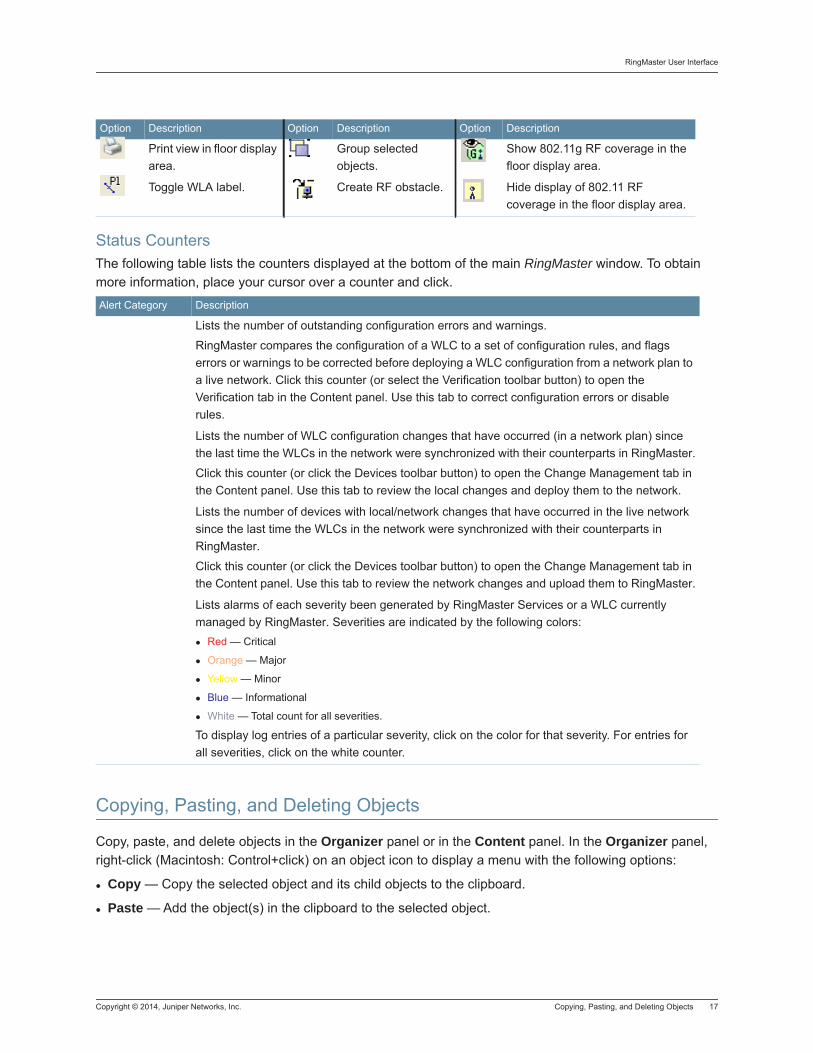
Status CountersThe following table lists the counters displayed at the bottom of the main RingMaster window. To obtain more information, place your cursor over a counter and click.
Copying, Pasting, and Deleting Objects
Copy, paste, and delete objects in the Organizer panel or in the Content panel. In the Organizer panel, right-click (Macintosh: Control+click) on an object icon to display a menu with the following options:
Copy — Copy the selected object and its child objects to the clipboard.
Paste — Add the object(s) in the clipboard to the selected object.
Print view in floor display area.
Group selected objects.
Show 802.11g RF coverage in the floor display area.
Toggle WLA label. Create RF obstacle. Hide display of 802.11 RF coverage in the floor display area.
Alert Category Description
Config
Lists the number of outstanding configuration errors and warnings.
RingMaster compares the configuration of a WLC to a set of configuration rules, and flags errors or warnings to be corrected before deploying a WLC configuration from a network plan to a live network. Click this counter (or select the Verification toolbar button) to open the Verification tab in the Content panel. Use this tab to correct configuration errors or disable rules.
Local Changes
Lists the number of WLC configuration changes that have occurred (in a network plan) since the last time the WLCs in the network were synchronized with their counterparts in RingMaster.
Click this counter (or click the Devices toolbar button) to open the Change Management tab in the Content panel. Use this tab to review the local changes and deploy them to the network.
Network Changes
Lists the number of devices with local/network changes that have occurred in the live network since the last time the WLCs in the network were synchronized with their counterparts in RingMaster.
Click this counter (or click the Devices toolbar button) to open the Change Management tab in the Content panel. Use this tab to review the network changes and upload them to RingMaster.
Alarms
Lists alarms of each severity been generated by RingMaster Services or a WLC currently managed by RingMaster. Severities are indicated by the following colors:
Red — Critical
Orange — Major
Yellow — Minor
Blue — Informational
White — Total count for all severities.
To display log entries of a particular severity, click on the color for that severity. For entries for all severities, click on the white counter.
Option Description Option Description Option Description
RingMaster User Interface
18 Copying, Pasting, and Deleting Objects Copyright © 2014, Juniper Networks, Inc.
Paste Replace — Replace the like-named object(s) in the selected object with the object(s) in the clipboard.
Delete — Remove the selected object from the network plan.
Use Copy and Paste to create a new object. Use Copy and Paste Replace to replace an object with another instance of the same type of object. You can copy and paste objects listed in tables in the Content panel using copy and paste icons. (See Copy and Paste in the Content Panel.) To delete an object in a table, select the object and click Delete.
Copy and Paste in the Organizer Panel
To create a new object in the Organizer panel:
1. Select the object you want to copy in the Organizer panel.
2. Right-click (Macintosh: Control+click) on the object and select Copy.
3. Select the parent object to add copied object.
4. Right-click (Macintosh: Control+click) on the parent object and select Paste.
RingMaster displays a configuration wizard. Use this configuration wizard to modify the name and other parameters as applicable. When finished, a new copy of the object appears under the parent object.
Copy and Paste Replace in the Organizer Panel
To replace an object with the Copy and Paste Replace options:
1. Select the object you want to copy in the Organizer panel.
2. Right-click (Macintosh: Control+click) on the object and select Copy.
3. Select the object you want to replace.
4. Right-click (Macintosh: Control+click) on the parent object and select Paste Replace.
RingMaster displays a configuration wizard. Use this configuration wizard to modify the name and other parameters as applicable. When finished, a new copy of the object appears under the parent object.
Copy and Paste in the Content Panel
1. Select the objects (rows).
− To select a single object, click on the row for the object.
− To select multiple contiguous objects, click Shift while selecting them.
− To select non-contiguous objects, click Control (Macintosh: Command) while selecting them.
2. Click the Copy icon .
3. Click the Paste icon . A properties dialog appears.
4. Edit settings to make the new object unique from the object copied, then click OK or Finish to save changes and close the configuration wizard.
Configuration Using Dialog BoxesRingMaster dialog boxes allow you to specify options and perform actions. You can right-click (on Macintosh it is Control+click) on many objects to display optional actions.
Copyright © 2014, Juniper Networks, Inc. Copying, Pasting, and Deleting Objects 19
RingMaster User Interface
Configuration Using WizardsClicking on an option in the Tasks panel opens a configuration wizard. Configuration wizards enable configuration of basic settings for an object. A “wizard” presents the next dialog you should use to proceed, in the recommended sequence, to complete an overall configuration task. Although there are other ways to view and/or alter configuration settings later, wizards are helpful for completing initial setups using best practices.After configuring settings and closing a wizard, a new object is added to a table in the Content panel for most types of WLC objects. Some objects have advanced, infrequently modified settings not configurable using a wizard. To configure advanced settings for an object listed in the Content panel, select an object and click Properties. This opens a configuration dialog containing all configurable settings for an object, including advanced settings. For simple changes, select multiple objects and click Properties to make changes for all selected objects. For example, to disable or re-enable multiple ports, select affected ports, click Properties, change port state in the dialog, and then close it. Changes take effect on all of the selected ports.

RingMaster User Interface
20 Copying, Pasting, and Deleting Objects Copyright © 2014, Juniper Networks, Inc.
Copyright © 2014, Juniper Networks, Inc. Overview
Working with Network Plans
Working with Network Plans
Overview
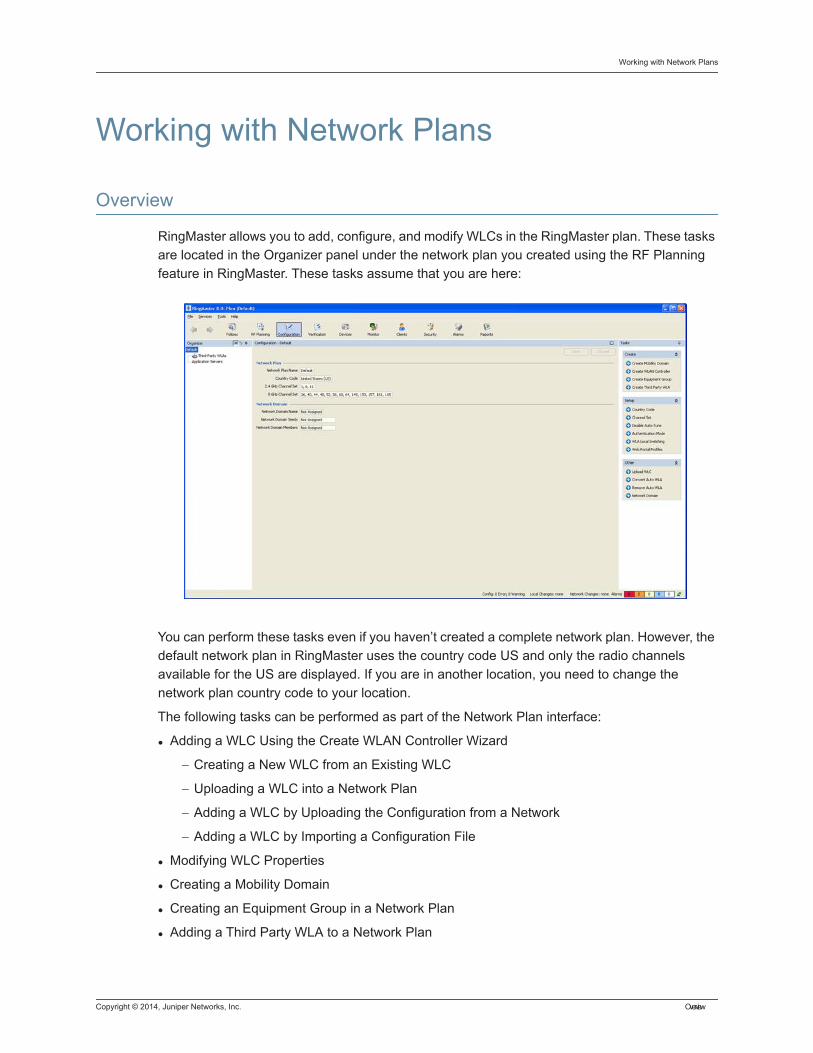
RingMaster allows you to add, configure, and modify WLCs in the RingMaster plan. These tasks are located in the Organizer panel under the network plan you created using the RF Planning feature in RingMaster. These tasks assume that you are here:
You can perform these tasks even if you haven’t created a complete network plan. However, the default network plan in RingMaster uses the country code US and only the radio channels available for the US are displayed. If you are in another location, you need to change the network plan country code to your location.
The following tasks can be performed as part of the Network Plan interface:
Adding a WLC Using the Create WLAN Controller Wizard
− Creating a New WLC from an Existing WLC
− Uploading a WLC into a Network Plan
− Adding a WLC by Uploading the Configuration from a Network
− Adding a WLC by Importing a Configuration File
Modifying WLC Properties
Creating a Mobility Domain
Creating an Equipment Group in a Network Plan
Adding a Third Party WLA to a Network Plan
2 Overview Copyright © 2014, Juniper Networks, Inc.
Changing the Country Code for a Network Plan
Changing the Channel Set for a Network Plan
Disabling Auto-tune on a Network Plan
Configuring the Authentication Mode for a WLC
Local Packet Switching on WLAs
Configuring Web Portal Profiles
Converting an Auto WLA into a Static WLA
Removing Auto WLAs
Setting Up a Network Domain
Setting Up WLC to WLC Security
Copyright © 2014, Juniper Networks, Inc. Adding a WLC Using the Create WLAN Controller Wizard
Adding a WLC Using the Create WLAN Controller Wizard
You can use any of the following methods to add a WLC to a network plan:
Allow RingMaster to create a WLC as part of RF planning.
Use the Create WLAN Controller wizard.
Copy and paste an existing WLC in a network plan.
Upload a WLC from the network.
Import an XML configuration file for a WLC.
In this section, the Create WLAN Controller wizard is explained.
1. Select the Configuration Navigation Bar button.
2. In the Tasks panel, select Create WLAN Controller.
3. Enter a WLC Name, and select a WLC Model from the list.
4. Select a Software Version for the WLC and enter an Enable Password. Click Next.
5. In the WLC IP Address dialog, enter an IP Address and Gateway IP for this new WLC. Click Next.
6. Now you can select Ports and Port Groups to add to the VLAN and tag those you want. Click Next.
7. You next select a Mobility Domain and Wiring Closet, and select Enable Cluster if you want the WLC to become a member of a cluster configuration. Click Next.
8. Now you select areas to configure by clicking check boxes as desired for Static Route, SNMP, VLANs and RADIUS Servers. Click Next.
9. You can select or create a static route if a gateway is being used. Either select an existing route and click Next or select Create and click Next.
10. If you select Create, you see the following dialog.
11. Select Default Route check box or specify a Destination IP Address, Gateway IP address and select a Metric for the route and then click OK.
12. Use check boxes to configure security level and allowed protocols for the SNMP interface. Click Next.
13. The next dialog allows you to set Notification Target Properties.
14. The next dialog allows you to set a Security Model and Security Type.
15. If you selected USM, click Next and go to step 15. If you selected V1, you see the RingMaster Notification Target: SNMP Community dialog:
16. Enter a Community String, select an Access or Group, an Access Type, and a Group if that was selected, then click Next.
17. You see the RingMaster Notification Target: USM User dialog
18. Enter information and make selections, then click Next.
19. You see the RingMaster Notification Target: USM User dialog, where you enter a Username, Access or Group, Access Type and Group if selectable
Creating a New WLC from an Existing WLC Copyright © 2014, Juniper Networks, Inc.
20. Click Next.
21. You see the Configure VLANs dialog, where you create a new one or select an existing VLAN.
22. When done, click Next and you will go to the Configure VLANs dialog described in step 16. When you finish selections on this dialog and click Next, you see the Optional: RADIUS Servers dialog below:
23. Select an existing RADIUS Server and Finish, or click Create to create a new one.
24. If you click Create you see the following dialog:
25. Enter a server Name, IP Address, and a Key if desired, or select Use MAC as Password or enter an Authorization Password and select a MAC Address Format then click Next.
26. You see the RADIUS Server Group dialog. Click Finish.
Uploading a WLC into a Network PlanThe following steps can be used to upload a WLC into an existing network plan:
1. Select the Configuration Navigation bar button.
2. In the Tasks panel, select Upload WLC.
3. In the IP Address field, enter the IP address of the WLC.
4. In the Enable Password field, type the enable password for the WLC. This password must match the enable password creating using the set enablepass command in the CLI.
5. Click Next.
6. A dialogue box displays the upload progress.
7. After the Successfully uploaded device message is displayed, click Finish.
8. If error or warning messages are displayed, navigate to the Verification panel by clicking the button on the Navigation bar.
Creating a New WLC from an Existing WLC
You can copy and modify a WLC already in a network plan by copying and pasting the WLC in the Organizer panel.
1. Select the Configuration Navigation Bar button.
2. In the Organizer panel, select a WLC to copy, then right-click (Macintosh: Control+click) on the WLC and select Copy.
3. Right-click (Macintosh: Control+click) and select Paste. The WLAN Controller Properties wizard appears.
4. In the WLC Name field, type a name for the WLC (1 to 256 alphanumeric characters, with no spaces or tabs).
Informational Note: In each network plan or Mobility Domain, every WLC on the network must have a unique name.
Copyright © 2014, Juniper Networks, Inc. Creating a New WLC from an Existing WLC
5. Type the serial number for the WLC in the Serial Number field.
6. To modify the system IP address and VLAN, select them from the System VLAN/IP list. The system IP address determines the interface or source IP address MSS uses for system tasks, including the following:
Mobility Domain operations
Topology reporting for redundant MP access points
Default source IP address used in unsolicited communications such as AAA accounting reports and SNMP notifications
7. Click Management Interface.
8. To enable a WLC to be managed by RingMaster, select Managed. Until this option is selected, you cannot deploy the WLC configuration you create in RingMaster to an actual WLC in a network. This option also enables the Telnet to WLC and Launch Browser options in the Tasks panel. Selecting a WLC in the Organizer panel and clicking on Telnet to WLC in the Tasks panel opens communication as with the WLC via Telnet.Enter a username to begin a Telnet session.
9. To modify the management interface, select the IP interface and VLAN from the VLAN/IP list.
10. To modify the enable password, edit the string in the Enable Password field.
11. Click WLC Associations.
12. To change the Mobility Domain membership for a WLC, select the Mobility Domain from the Mobility Domain list. To leave the WLC out of all Mobility Domains, select Not Assigned.
13. To change the wiring closet membership for a WLC, select a closet from the Wiring Closet list. To leave the WLC out of all wiring closets, select Not Assigned.
14. Click OK to save changes.
15. Edit other parameters as required.
Adding a WLC by Uploading the Configuration from a NetworkIf you have already deployed a WLC in a network and want to add it to a network plan, upload the configuration for the WLC into RingMaster, edit the WLC, then re-deploy the WLC with the new parameters.)
Adding a WLC by Importing a Configuration FileYou can add a WLC to a network plan by importing a configuration file. Configurations are imported in XML format. Use the procedure in “Importing and Exporting Switch Configuration Files” in the RingMaster 7.1 Management Guide to import configuration files for WLCs.
Warning: After selecting Managed to enable management of a WLC by RingMaster, do not change this option unless advised to do so by Juniper Networks TAC. If you change a WLC to an unmanaged state in a network plan, all network operations (polling) stop for that WLC. If you change back to a managed state, the entire configuration of the WLC is replaced with settings from the network plan, which can result in loss of connectivity to the WLC.

Creating a New WLC from an Existing WLC Copyright © 2014, Juniper Networks, Inc.
Copyright © 2014, Juniper Networks, Inc. Modifying WLC Properties
Modifying WLC Properties
1. Select the Configuration Navigation Bar button.
2. Select a WLC from the Organizer panel. The WLC information is displayed in the Configuration panel.
3. To modify the WLC Name, edit the string in the WLC Name field.
4. To modify the serial number, edit the string in the Serial Number field.
5. To modify the system IP address and VLAN, select them from the System VLAN/IP list. The system IP address determines the interface or source IP address that MSS uses for system tasks, including the following:
Mobility Domain operations
Topology reporting for redundant access points
Default source IP address used in unsolicited communications such as AAA accounting reports and SNMP notifications.
6. To allow RingMaster management of the WLC, select Managed. You cannot deploy a WLC configuration using RingMaster until you enabled this option.
7. To modify the management IP address and VLAN, select them from the System VLAN/IP list.
8. To modify the enable password, edit the string in the Enable Password field.
9. To change the Mobility Domain membership for a WLC, select one from the Mobility Domain list.
10. To change a wiring closet membership for a WLC, select the closet from the Wiring Closet list. To remove a WLC from a wiring closet, select Not Assigned.
11. Click Save.
Informational Note: This option also enables the Launch Telnet and Launch Browser options in the Tasks panel.
Warning: After selecting Managed to enable management of the WLC by RingMaster, do not change this option unless advised to do so by Juniper Networks TAC. If you change a WLC to an unmanaged state in a network plan, all network operations (polling) stop for that WLC. If you change back to a managed state, the entire configuration of the WLC is replaced with the settings from the network plan, which can result in loss of connectivity to the WLC.

Modifying WLC Properties Copyright © 2014, Juniper Networks, Inc.
Copyright © 2014, Juniper Networks, Inc. Creating a Mobility Domain 1
Creating a Mobility Domain
Before you can perform this task, you must have more than one WLC in your network plan. To add WLCs to the network plan, see “Adding a WLC Using the Create WLAN Controller Wizard.”
1. Select the Configuration Navigation Bar button.
2. Select the network plan in the Organizer panel.
3. Select the Create Mobility Domain task in the Tasks panel. The Setup Mobility Domain wizard is displayed.
4. In the Name field, type the name for the Mobility Domain (1 to 16 characters, with no spaces or tabs). Click Next.
5. From the Available Devices list, select WLCs you want to add to a Mobility Domain.
6. Click Next.
7. Select the WLC to act as the primary seed WLC for the Mobility Domain.
8. To provide mobility domain redundancy, select a WLC to act as secondary seed. Click Finish.
For detailed information about this feature, refer to the Mobility System Software (MSS) Configuration Guide.
Informational Note: The Create Mobility Domain wizard requires you to select WLCs to place in a Mobility Domain and to select a seed WLC. Add WLCs to a network plan before you configure a Mobility Domain

2 Creating a Mobility Domain Copyright © 2014, Juniper Networks, Inc.
Copyright © 2014, Juniper Networks, Inc. Creating an Equipment Group in a Network Plan 1
Creating an Equipment Group in a Network Plan
An equipment group can contain the following types of objects:
Mobility Domain — All member devices are implicitly included as equipment group members.
Standalone WLC — A device not associated with a Mobility Domain
Mobility Domain member WLC — A device associated with a Mobility Domain where the Mobility Domain as a whole is not a member of the equipment group.
Equipment groups can be created under a top-level plan object, or under a Mobility Domain.
The equipment organizer tree is enhanced to support the concept of equipment groups. Equipment group nodes appear in the tree to contain associated device and/or MobilityDomain members.
Device nodes hang directly under an equipment group node, unless a device’s Mobility Domain is a member of the group. Selecting a device node, reveals any Mobility Domain membership information in the configuration view’s detail panel.
Cluster Configuration
Whenever a Mobility Domain is cluster-enabled, an associated Cluster node appears in the organizer. This node contains the cluster seeds, members, and the DomainConfiguration node. A Mobility Domain cluster node may appear multiple times in the tree. There is no method to assign a cluster as a whole to an equipment group. Only devices and MobilityDomains can be assigned to a group. One restriction is enforced regarding assignment of devices to equipment groups, which is that, if a device is a cluster seed, the other cluster seed must also be assigned to the same equipment group. This is required to ensure that a deploy target switchover is not rejected due to access control restrictions.
Before you can perform this task, you must have added WLCs and WLAs to the network plan.
1. Select the Configuration Navigation Bar button.
2. Select the network plan in the Organizer panel.
3. Click Create Equipment Group to open the wizard.
4. Enter a unique name to identify the Equipment Group.
5. Click Next.
6. From the list of Available Devices, select one or more WLCs and click Add.
7. The WLC is now added to the list of Current Members.
8. Click Finish to complete the task.
Equipment Groups appear in the Organizer panels with the Equipment Group name with brackets around the WLC icon.

2 Creating an Equipment Group in a Network Plan Copyright © 2014, Juniper Networks, Inc.
Copyright © 2014, Juniper Networks, Inc. Setting Up a Network Domain 1
Setting Up a Network Domain
A Network Domain is a system of centralized network administration and allows you to group WLCs together in a network group.
1. In the Organizer Panel, select Default, or your network plan name, as the network plan.
2. In the Tasks Panel, select Network Domain.
3. In the Setup Network Domain wizard, enter a name for the network domain.
4. Set up the network domain seeds by selecting a WLC from the Available Devices list, and clicking Add to move it to the Current Devices list.
5. Click Next.
6. Add any additional WLCs to the network domain or click Finish to complete the wizard.
Informational Note: You can configure only one Network Domain per Network Plan.

2 Setting Up a Network Domain Copyright © 2014, Juniper Networks, Inc.
Copyright © 2014, Juniper Networks, Inc. Changing the Country Code for a Network Plan 1
Changing the Country Code for a Network Plan
Select a country code to apply to all WLCs in the network plan. To use different country codes within the network plan, configure the country code for the site where the WLCs are associated. After the country code has changed, you must recalculate the existing RF plans.
1. Select Configuration from the Navigation Bar.
2. In the Organizer panel, select Default or your network plan.
3. In the Tasks panel under Setup, select Country Code.
4. The Change Country Code window is displayed.
5. Select the country from the Country Code list.
6. Modify the Channel sets for 2.4 GHz and 5 GHz, if desired.
7. Click Next.
8. The Updating Country Code progress is displayed. All messages related to updating the country code are displayed in this window.
9. Click Finish to complete the configuration.

2 Changing the Country Code for a Network Plan Copyright © 2014, Juniper Networks, Inc.
Copyright © 2014, Juniper Networks, Inc. Changing the Channel Set for a Network Plan 1
Changing the Channel Set for a Network Plan
Select a country code to apply to all WLCs in the network plan. To use different country codes within the network plan, configure the country code for the site where the WLCs are associated. After the country code has changed, you must recalculate the existing RF plans.
1. Select Configuration from the Navigation Bar.
2. In the Organizer panel, select Default or your network plan.
3. In the Tasks panel under Setup, select Channel Set.
4. The Channel Set Properties window is displayed.
5. Modify the Channel sets for 2.4 GHz and 5 GHz.
6. Click OK.

2 Changing the Channel Set for a Network Plan Copyright © 2014, Juniper Networks, Inc.
Copyright © 2014, Juniper Networks, Inc. Disabling Auto-tune on a Network Plan 1
Disabling Auto-tune on a Network Plan
One feature that RingMaster provides is the ability to apply Auto-Tune settings to WLAs in a network. This is useful when you want to use Auto-Tune to determine optimal channel and power settings and apply those settings to individual radios. If you disable Auto-Tune, you can manually apply power settings and channels to radios. To facilitate this, RingMaster provides the Disable Auto-Tune task. This task is available in the Tasks panel when a network plan object is selected in the Configuration panel.
To use this feature:
1. Select Configuration from the Navigation Bar.
2. In the Organizer panel, select Default or your network plan.
3. In the Tasks panel under Setup, select Disable Auto-Tune.
4. The Select Scope window is displayed.
5. If desired, you can save the Auto-tune Values, including tuned channel and tuned power.
6. Select the scope to disable Auto-Tune.
7. Click Next.
8. The Applying Auto-Tune Settings progress is displayed. Information about the Auto-Tune settings is displayed in this window.
9. Click Finish.

2 Disabling Auto-tune on a Network Plan Copyright © 2014, Juniper Networks, Inc.
Copyright © 2014, Juniper Networks, Inc. Removing Auto WLAs 1
Removing Auto WLAs
RingMaster automatically updates information for an Auto WLA in a network plan either when the WLA is converted into a configured WLA, or it re-boots and connects to a different WLC. If an Auto WLA leaves the network without being converted into a statically configured WLA or connecting to a different WLC, RingMaster continues to list the WLA as a device being managed by the WLC.
In this case, you can manually remove the WLA from the Auto WLA list.
To remove an Auto WLA:
1. Select the Configuration Navigation Bar button.
2. In the Organizer panel, select a WLC.
3. In the Tasks panel, select Remove Auto WLAs. The Remove Auto WLA wizard appears. WLAs that were configured using a Distributed WLA template are listed.
4. Select the Auto WLA that is no longer on the network.
5. Click Next.
6. Click Finish.
Informational Note: This procedure does not remove an active Auto WLA. To remove an Auto WLA that is still attached to the network, remove it from the network. (Unplug it or power it down.) Then use this procedure to remove it from the Auto WLA list.

Copyright © 2014, Juniper Networks, Inc. Removing Auto WLAs 2
Copyright © 2014, Juniper Networks, Inc. Converting an Auto WLA into a Static WLA 1
Converting an Auto WLA into a Static WLA
Distributed WLAs not configured on any WLCs in a mobility domain can be booted and managed by a WLC if the WLC has a profile for distributed WLAs, and has capacity to manage the WLA. A WLA that is booted and managed using a distributed WLA profile is called an Auto WLA. You can convert the temporary connection of an Auto WLA to a WLC into a permanent, statically configured connection on the WLC.
To convert an Auto WLA:
1. Select the Configuration Navigation Bar button.
2. In the Organizer panel, select a WLC.
3. In the Tasks panel, select Convert Auto WLAs. As that were configured using a Distributed WLA template are listed in the Convert Auto WLA wizard.
4. Select the WLAs you want to convert into statically configured WLAs.
5. Click Next.
6. Click Finish.

2 Converting an Auto WLA into a Static WLA Copyright © 2014, Juniper Networks, Inc.
Copyright © 2014, Juniper Networks, Inc. Local Packet Switching on WLAs 1
Local Packet Switching on WLAs
WLAs can be configured to perform local packet switching. Local packet switching allows packets to switch directly from a WLA to the wired network without passing through an intermediate WLC. When a WLA is configured to perform local switching, the WLC is removed from the forwarding path for client data traffic. When local switching is enabled, a client VLAN is directly accessible through the wired interface on a WLA. Packets can be switched directly to and from this interface.
Using the wizard forces all devices in a network plan that have identically named VLAN profiles to have the same settings. This can also be used to correct problems when uploading WLCs with different local switching values. Normally, when local switching is disabled on a WLA, packets are tunneled through the network back to a WLC and traffic is placed on the client VLAN. This process is called “overlay mode”. Overlay mode requires packets to be encapsulated, un-encapsulated — and possibly fragmented — which introduces latency in the path. Omitting a WLC from the forwarding path for client traffic eliminates tunnel encapsulation, and results in improved network performance.
Local packet switching is disabled by default. A WLA can be configured to switch packets for some VLANs locally and tunnel packets for other VLANs through the WLC switch.
Notes
Restricting Layer 2 forwarding for a VLAN is not supported if the VLAN is configured for local switching.
The DHCP restrict feature is not supported for locally switched clients.
When the set ap <apnum> port <portnum> type command is used to specify a port for a directly attached WLA, the WLA cannot be configured to perform local switching. However, a directly connected WLA with an unspecified port can perform local switching.
IGMP snooping is not supported with local switching.
1. Select Configuration from the Navigation Bar.
2. In the Organizer panel, select Default or your network plan.
3. In the Tasks panel under Setup, select WLA Local Switching.
4. The Setup WLA Local Switching window is displayed and lists the following information:
− WLA Name
− WLA Model
− WLA Connections
− Local Switching
− Profile
Informational Note: You must have a VLAN and WLAs configured before you can configure local packet switching.
2 Local Packet Switching on WLAs Copyright © 2014, Juniper Networks, Inc.
− Tunnel Affinity
5. You can enable local switching on all WLAs or individual WLAs by selecting them in the list and clicking OK.
6. You can also create a new VLAN profile or modify or delete existing VLAN profiles from local switching.
7. To assign a VLAN Profile to local switching, click Assign VLAN Profile.
8. The Assign VLAN Profile dialogue is displayed. You can select a VLAN profile from the list, select WLAs from the list of Available WLAs, and move the WLAs to the list of Current WLAs.
9. Click Finish to return to the Setup WLA Local Switching window.
10. Click OK to complete the configuration.
For detailed information on Local Switching, please see the Mobility System Software (MSS) Configuration Guide.
Copyright © 2014, Juniper Networks, Inc. Configuring Web Portal Profiles 1
Configuring Web Portal Profiles
WebAAA provides a simple and universal way to authenticate any user or device using a Web browser. A common application of WebAAA is to control access for guests on your network. When a user requests access to an SSID or attempts to access a Web page before logging onto the network, MSS displays a login page to the user’s browser. After the user enters a username and password, MSS validates the user information on the local database or RADIUS servers and grants or denies access based on whether the user information is found.
You can now customize your Web Portal Login pages as Web Portal Profiles, and then assign the profiles to users.
1. Select Configuration from the Navigation Bar.
2. In the Organizer panel, select Default or your network plan.
3. In the Tasks panel under Setup, select Web Portal Profile to display the configuration wizard.
4. The Web Portal Profile window is displayed and contains one default profile for use by education campuses. You can navigate to these by clicking Upload. The default pages and images are located under \Program Files\Juniper Networks\RingMaster\webapps\admin\.
− Profile Name - name of the Web Portal Profile
− Login Page - location of the HMTL page displayed for the login screen.
− Logout Page - location of the HMTL page displayed to users upon logging off of the network.
− Image Logo - location of any images displayed as a logo on the HTML pages.
− Service Profile - name of the service profile to apply the Web login.
5. Click Next.
6. Select a service profile from the list and move it to the Current Members list.
7. Click Finish to complete the configuration.
You can create your own HTML pages and place them in the same location, \Program Files\Juniper Networks\RingMaster\webapps\admin\, as the default pages.

2 Configuring Web Portal Profiles Copyright © 2014, Juniper Networks, Inc.
Copyright © 2014, Juniper Networks, Inc. Setting Up WLC to WLC Security 1
Setting Up WLC to WLC Security
You can enhance security on your network by enabling WLC-WLC security. WLC-WLC security encrypts management traffic exchanged by WLC switches in a Mobility Domain.
When WLC-WLC security is enabled, management traffic among WLC switches in the Mobility Domain is encrypted using AES. The keying material is dynamically generated for each session and passed among switches using configured public keys.
MSS supports 2048-bit keys in addition to 128-bit keys.
1. From the Organizer panel, select a Mobility Domain.
2. From the Task panel, under Setup, click WLC-WLC Security to display the wizard.
3. From the Security Mode list, select Required. None is selected by default.
4. Click Next.
5. If you are using public keys from a WLC, select Retrieve Keys. If you are not using this feature, click Next.
6. If you select Retrieve Keys, then the public keys are obtained from the WLCs in the Mobility Domain.
7. Verify the public keys and click Finish.

2 Setting Up WLC to WLC Security Copyright © 2014, Juniper Networks, Inc.
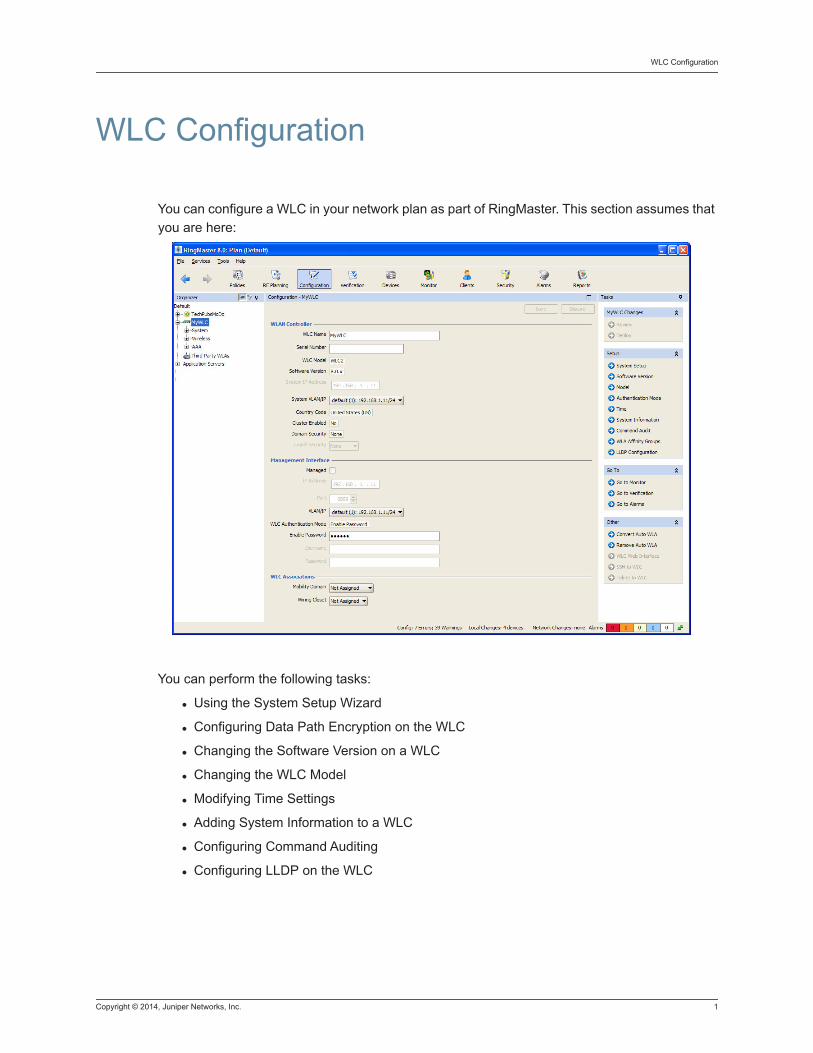
Copyright © 2014, Juniper Networks, Inc. 1
WLC Configuration
WLC Configuration
You can configure a WLC in your network plan as part of RingMaster. This section assumes that you are here:
You can perform the following tasks:
Using the System Setup Wizard
Configuring Data Path Encryption on the WLC
Changing the Software Version on a WLC
Changing the WLC Model
Modifying Time Settings
Adding System Information to a WLC
Configuring Command Auditing
Configuring LLDP on the WLC

2 Copyright © 2014, Juniper Networks, Inc.
Copyright © 2014, Juniper Networks, Inc. Using the System Setup Wizard 1
Using the System Setup Wizard
You can configure and display information for the following features on a WLC
WLC
Static Route
SNMP
VLANs
AAA
Wireless Services
WLA
1. From the Organizer panel, select a WLC and then System Setup.
2. The System Setup Wizard is displayed. To continue, click Next.
3. Enter a unique name for the WLC, and enter the serial number. Click Next.
4. From the System Configuration Areas, select the ares that you want to configure on the WLC.You can select from the following areas:
See “Configuring Static Routes”
Configuring SNMP Using SNMP V1 or V2c
Configuring VLANs
Creating a RADIUS Server
Configuring Wireless Services
Converting Auto WLAs
5. Click Finish to complete the configuration.

2 Using the System Setup Wizard Copyright © 2014, Juniper Networks, Inc.
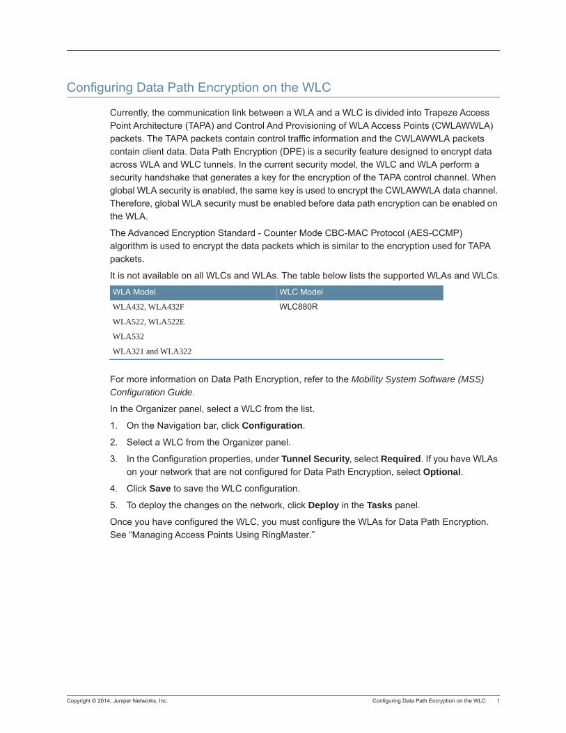
Copyright © 2014, Juniper Networks, Inc. Configuring Data Path Encryption on the WLC 1
Configuring Data Path Encryption on the WLC
Currently, the communication link between a WLA and a WLC is divided into Trapeze Access Point Architecture (TAPA) and Control And Provisioning of WLA Access Points (CWLAWWLA) packets. The TAPA packets contain control traffic information and the CWLAWWLA packets contain client data. Data Path Encryption (DPE) is a security feature designed to encrypt data across WLA and WLC tunnels. In the current security model, the WLC and WLA perform a security handshake that generates a key for the encryption of the TAPA control channel. When global WLA security is enabled, the same key is used to encrypt the CWLAWWLA data channel. Therefore, global WLA security must be enabled before data path encryption can be enabled on the WLA.
The Advanced Encryption Standard - Counter Mode CBC-MAC Protocol (AES-CCMP) algorithm is used to encrypt the data packets which is similar to the encryption used for TAPA packets.
It is not available on all WLCs and WLAs. The table below lists the supported WLAs and WLCs.
For more information on Data Path Encryption, refer to the Mobility System Software (MSS) Configuration Guide.
In the Organizer panel, select a WLC from the list.
1. On the Navigation bar, click Configuration.
2. Select a WLC from the Organizer panel.
3. In the Configuration properties, under Tunnel Security, select Required. If you have WLAs on your network that are not configured for Data Path Encryption, select Optional.
4. Click Save to save the WLC configuration.
5. To deploy the changes on the network, click Deploy in the Tasks panel.
Once you have configured the WLC, you must configure the WLAs for Data Path Encryption. See “Managing Access Points Using RingMaster.”
WLA Model WLC Model
WLA432, WLA432F WLC880R
WLA522, WLA522E
WLA532
WLA321 and WLA322

2 Configuring Data Path Encryption on the WLC Copyright © 2014, Juniper Networks, Inc.
Copyright © 2014, Juniper Networks, Inc. Changing the Software Version on a WLC 1
Changing the Software Version on a WLC
1. To change the software version on a WLC, select the WLC in the Organizer panel.
2. In the Tasks list, under Setup, select Software Version.
3. Select the software version from the list, and click OK.

2 Changing the Software Version on a WLC Copyright © 2014, Juniper Networks, Inc.
Copyright © 2014, Juniper Networks, Inc. Changing the WLC Model 1
Changing the WLC Model
1. To change the model of a WLC, select the WLC in the Organizer panel.
2. In the Tasks list, under Setup, select Model.
3. Select the model from the list, and click OK.
4. RingMaster updates the model on the WLC. You can see the changes in the Change Model Progress window.
5. Click Finish to complete the change.

2 Changing the WLC Model Copyright © 2014, Juniper Networks, Inc.
Copyright © 2014, Juniper Networks, Inc. Configuring the Authentication Mode for a WLC 1
Configuring the Authentication Mode for a WLC
Select the authentication mode for logging into a WLC.
1. In the Organizer panel, select a WLC from the list.
2. From the Tasks list, under Setup, select Authentication Mode to display the Change Authentication Mode window.
3. From the WLC Authentication Mode list, select Enable Password or AAA.
4. If you select Enable Password, enter the password into the Enable Password field.
5. Click Finish.
6. If you select AAA, enter the information for the Username and Password.
7. Click Next.
8. The Changing Authentication Settings Progress window displays information about the status and also any errors encountered during the process.
9. Click Finish to close the wizard.
Informational Note: Be sure to enable Access Control before changing the Authentication Mode to AAA.

2 Configuring the Authentication Mode for a WLC Copyright © 2014, Juniper Networks, Inc.

Copyright © 2014, Juniper Networks, Inc. Modifying Time Settings 1
Modifying Time Settings
You can specify the number of hours (and optionally minutes) the real-time clock for a WLC is offset from Coordinated Universal Time (UTC) — also known as Greenwich Mean Time (GMT). The Network Time Protocol (NTP) uses time zone information if it is enabled. You can also specify whether a WLC modifies this clock during daylight savings time or similar summertime period.
To set the time zone properties:
1. From the Organizer panel, select a Mobility Domain.
2. From the Tasks panel, under Setup, click Time. In the Name field, type a name for the time zone (1 to 16 alphanumeric characters, with no spaces or tabs).
3. From the Offset Hours list, select the number of hours (between -23 and 23) to subtract from or add to UTC.
4. Optionally, in the Offset Minutes field, select a number of minutes (between -59 to 59) to subtract from or add to UTC.
5. In the DST Name field, type a name for the summertime offset (1 to 16 alphanumeric characters, with no spaces or tabs).
6. From the Start Month list, select the month of the year when the time change starts.
7. From the Start Week list, select the week of the month when the time change starts (First, Second, Third, Fourth, or Last).
8. From the Start Day list, select the day of the week when the time change starts.
9. In the Start Hour field, specify the hour (between 0 and 23) to start the time change.
10. In the Start Minute field, specify the minute (between 0 and 59) when the time change starts.
11. From the End Month list, select the month of the year when the time change ends.
12. From the End Week list, select the week of the month when the time change ends (First, Second, Third, Fourth, or Last).
13. From the End Day list, select the day of the week when the time change ends.
14. In the End Hour field, specify the hour (between 0 and 23) when the time change ends.
15. In the End Minute field, specify the minute (between 0 and 59) when the time change ends.
16. Click OK..

2 Modifying Time Settings Copyright © 2014, Juniper Networks, Inc.
Copyright © 2014, Juniper Networks, Inc. Adding System Information to a WLC 1
Adding System Information to a WLC
1. To modify system information on a WLC, select the WLC in the Organizer panel.
2. In the Tasks list, under Setup, select System Information.
3. You can configure the following information on the WLC:
Contact - enter contact information for a network administrator.
Location - enter the location of the WLC.
Prompt - change the prompt information on the CLI.
Message of the Day - create a message of the day to display on the WLC.
Acknowledge Mode - enable Acknowledge Mode and create an Acknowledge Message.
4. Click Finish to complete the change.

2 Adding System Information to a WLC Copyright © 2014, Juniper Networks, Inc.
Copyright © 2014, Juniper Networks, Inc. Configuring Command Auditing 1
Configuring Command Auditing
MSS can log commands used at the CLI and send them to a RADIUS server. All commands, including show commands, that complete successfully or fail are logged on the RADIUS server. The command accounting message includes the following elements:
Timestamp
TTY Port
Username
Source IP address
Command issued
Command status (success or failure)
You can also configure primary and secondary RADIUS servers to log CLI commands.
When command auditing is enabled, all valid CLI commands are captured and logged to a RADIUS server.
For details on the RADIUS commands, see the Mobility System Software (MSS) Configuration Guide.
1. To configure command auditing on a WLC, select the WLC in the Organizer panel.
2. In the Tasks list, under Setup, select Command Audit.
3. Select the log level of Command Auditing:
Default — tracks all operations that affect the state of the WLC.
None — no operations are tracked.
All — tracks all operations on the WLC.
4. Configure the size of the log file that saves the command audit trail. The default value is 500 KB on the WLC.
5. Select an AAA server from the list of configured Server Groups. You must select a RADIUS server group.
6. Add it to the list of Current AAA Server Groups.
7. Click Finish to complete the configuration.

2 Configuring Command Auditing Copyright © 2014, Juniper Networks, Inc.
Copyright © 2014, Juniper Networks, Inc. Configuring the WLA Affinity Groups for a WLC 1
Configuring the WLA Affinity Groups for a WLC
WLA Affinity groups are configured on each cluster member. This information is shared in the cluster database so that seeds have information on the WLA affinity group memberships of all cluster members. Based on the IP address of the WLA, the seed selects the PAM from the group of WLCs with a configured affinity for that subnet. In the event of a WLC failure, the WLA fails over to a controller outside of a preferred group. When the WLC is restored, the WLA reverts back to the preferred WLC.
WLA load balancing takes into consideration which subnet that the WLA is located and places the WLA in the appropriate affinity group. You must set the affinity on the Mobility Domain configuration. This information is shared in a cluster database, and based on the IP address of the WLA, the seed selects the PAM and SAM from the group of WLCs with the configured affinity for that subnet. Each cluster member can belong to one or more affinity subnets.
1. Select Configuration from the Navigation Bar.
2. In the Organizer panel, select a WLC.
3. In the Tasks panel, select WLA Affinity Groups.
4. The Setup WLA Affinity Groups wizard is displayed.
5. Click Create.
6. In the WLA Affinity Group IP Address field, enter the IP Address including the subnet.
7. Click Finish to complete the configuration.

2 Configuring the WLA Affinity Groups for a WLC Copyright © 2014, Juniper Networks, Inc.
Copyright © 2014, Juniper Networks, Inc. Configuring LLDP on the WLC 1
Configuring LLDP on the WLC
Link Layer Discovery Protocol (LLDP) is a vendor-neutral link layer protocol used by network devices to advertise identity, capabilities, and neighbors.
Link Layer Discovery Protocol-Media Endpoint Discovery (LLDP-MED) is an extension to LLDP that operates between endpoint devices such as IP phones and network devices such as switches. Specifically, it provides support for voice over IP (VoIP) applications and provides additional TLVs for capabilities discover, network policy, Power over Ethernet (PoE), and inventory management.
LLDP-MED supports the following TLVs:
LLDP-MED capabilities TLV — Allows LLDP-MED endpoints to determine the capabilities of a connected device and if those capabilities are enabled.
Network Policy TLV — Allows both network connectivity devices and endpoints to advertise VLAN configurations and associated Layer 2 and Layer 3 attributes for the specific appliance on that port. For example, a WLC can notify a VoIP phone to use a specific VLAN.
Power management TLV — Enables advanced power management between LLDP-MED endpoint and network connectivity devices. Allows WLCs and VoIP phones to convey power information, such as the type of power, power priority, and the amount of power required by the device.
Inventory management TLVs — Allows an endpoint to transmit detailed inventory information to a WLC, including hardware revision, firmware version, software version, serial number, manufacturer name, model name, and asset ID.
LLDP and LLDP-MED cannot operate simultaneously on a network. By default, network devices send only LLDP packets until LLDP-MED packets are received from an endpoint device. The network device then sends out LLDP-MED packets until it receives LLDP packets.
To configure LLDP using RingMaster, use the following steps:
1. In the Organizer panel, select a WLC from the Network Plan.
2. Under Setup, click LLDP Configuration.
3. Under Global Protocol Configuration, Enable LLDP is selected by default. LLDP is enabled by default. To disable the feature, clear the checkbox.
4. You can change the following values or leave them as the default values.
a. Transmission Interval [seconds] — the default value is 30 seconds with a range of 5 to 32768 seconds.
b. Hold Time [seconds] — the default value is 120 seconds with a range o 0 to 65535 seconds.
c. Re-initialization Delay [seconds] — the default value is 2 seconds with a range of 2 to 5 seconds.
d. Transmit Delay [seconds] — the default value is 2 seconds with a range of 1 to 8192 seconds.
5. Under Advertised TLVs, you can select the type of TLVs to advertise on the network. Available TLVs are System Capabilities, System Name, and System Description.
6. Click OK to save the configuration.
7. Click Deploy to send the changes to the WLC.
2 Configuring LLDP on the WLC Copyright © 2014, Juniper Networks, Inc.
8. To configure LLDP on a WLA, select Access Point in the Organizer panel to display a list of WLAs on the network.
9. Select a WLA, and click Properties.
10. On the LLDP tab, under LLDP Configuration, select a parameter from the LLDP Mode list.The WLA does not collect data about neighbors so the parameters RX and RXTX modes are not available. therefore, the WLA only advertises its presence, but cannot process incoming LLDP frames.
11. LLDP-MED is enabled by default.
12. To send information about power management, select Power via MDI. Media Dependent Interface (MDI) information is collected on the Ethernet interface.
13. To send information about inventory management, select Inventory.
14. Click OK to save the configuration.
15. To configure LLDP on a port, select Ports from the System list.
16. Select a port from the list of available ports, and click Properties.
17. For 10/100/1000 Ethernet Ports, under LLDP Configuration, select Tx, Rx, TxRx, or None. TxRx is selected by default.
18. For Gigabit Ethernet Ports, under LLDP Configuration, select Tx, Rx, TxRx, or None. TxRx is selected by default.
19. Click OK to save the configuration.
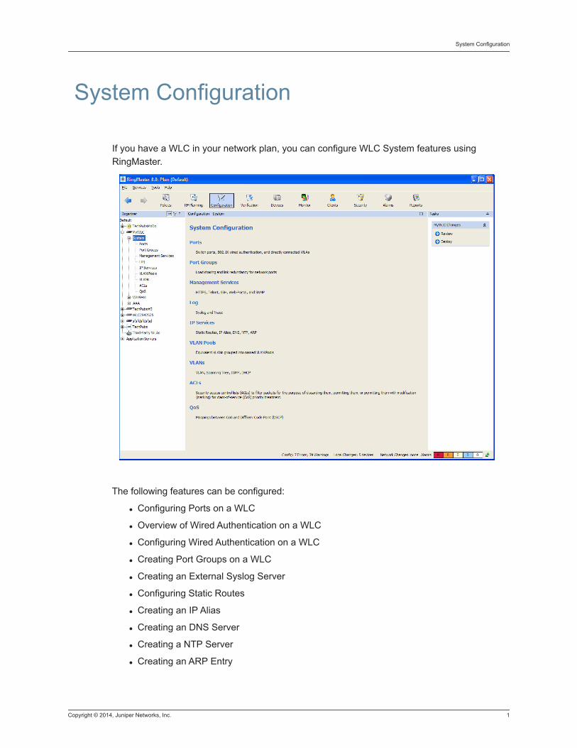
Copyright © 2014, Juniper Networks, Inc. 1
System Configuration
System Configuration
If you have a WLC in your network plan, you can configure WLC System features using RingMaster.
The following features can be configured:
Configuring Ports on a WLC
Overview of Wired Authentication on a WLC
Configuring Wired Authentication on a WLC
Creating Port Groups on a WLC
Creating an External Syslog Server
Configuring Static Routes
Creating an IP Alias
Creating an DNS Server
Creating a NTP Server
Creating an ARP Entry

2 Copyright © 2014, Juniper Networks, Inc.
Creating a VLAN Profile
Configuring Spanning Tree Properties
Creating an Access Control List (ACL)
Creating a Quality of Service (QoS) Profile
Copyright © 2014, Juniper Networks, Inc. Configuring Ports on a WLC 1
Configuring Ports on a WLC
A WLC port can be one of the following types:
Network port — A network port is a Layer 2 switch port connecting the WLC to other networking devices such as switches and routers.
WLA port — A WLA connects the WLC to a WLA. The port also can provide power to the WLA. Wireless users are authenticated on the network through a WLA port.
Wired authentication port — A wired authentication port connects the WLC to user devices, such as workstations, that must authenticate in order to access the network.
All WLC ports are network ports by default. You must set the port type for ports directly connected to WLAs and for ports on wired user stations that must authenticate in order to access the network. When you change port type, MSS applies default settings appropriate for the port type. Table 2 lists the default settings applied for each port type.
You can configure and display information for the following port parameters:
Name
State
Type (network, WLA, or wired authentication)
Speed and autonegotiation
Power over Ethernet (PoE) state
Media type (gigabit Ethernet ports only)
Load sharing (see Port Groups.)
1. From the Organizer panel, select a WLC and then under System, select Ports.
2. To view the 10/100 Ethernet Port Properties, select a Port and then click Properties.
3. The 10/100 Ethernet Port Properties window is displayed.
4. In the Name field, type a port name (1 to 16 alphanumeric characters, no spaces or tabs).
5. The port is enabled by default. To disable the port, clear the Enabled checkbox.
6. Select SNMP Link Traps if desired. By default, notifications for link state changes are disabled. If you enable them, SNMP link traps are sent when the port state changes, and RingMaster also polls and monitors the status of the port. To generate the LinkDown and LinkUp SNMP traps, you must enable this option.
NOTE: You must globally enable SNMP traps in order to receive notification.
7. To specify the speed of a 10/100 Ethernet port, select one of the following:
Auto — Sets the port to automatically detect the traffic speed and set the speed accordingly. This is the default value.
10 — Sets the speed to 10 Mbps.
100 — Sets the speed to 100 Mbps.
The port speed for gigabit Ethernet ports is 1000 Mbps and cannot be configured.
2 Configuring Ports on a WLC Copyright © 2014, Juniper Networks, Inc.
8. To specify the operating mode of a 10/100 Ethernet port, select Half for half-duplex or Full for full-duplex mode.
9. To enable PoE on a 10/100 Ethernet port, select PoE Enabled. By default, PoE is disabled. To disable PoE, clear PoE Enabled.
10. .For a gigabit Ethernet port (if supported by the WLC), select the interface you want to enable.
GBIC — Enables the fiber interface and disables the copper interface.
RJ45 — Enables the copper interface and disables the fiber interface.
A port supports only the physical interface you select. The other interface is disabled. The port cannot dynamically move between one interface and the other.
11. To configure Link Layer Discovery Protocol (LLDP) for the selected port, you can select from one of the following Operation Modes:
TxRx — Transmit and Receive LLDP packets.
Tx — Transmit LLDP packets
Rx — Receive LLDP packets
None — Disable LLDP on the port.
12. Click Save.
Copyright © 2014, Juniper Networks, Inc. Changing Port Settings on a WLC 1
Changing Port Settings on a WLC
Gigabit Ethernet Port Properties1. In the Organizer panel, select a WLC from the list.
2. Expand the System options, and select Ports.
3. Select a port from the Gigabit Ethernet Port list and click Properties.
4. In the Name field, type a port name (1 to 16 alphanumeric characters, no spaces or tabs).
5. Clear the Enabled checkbox if you want to disable the port. Click OK to complete the configuration. If you want to make additional changes to the settings, go to the next step.
6. Select SNMP Link Traps if desired. By default, notifications for link state changes are disabled. If you enable them, SNMP link traps are sent when the port state changes, and RingMaster also polls and monitors the status of the port. To generate the LinkDown and LinkUp SNMP traps, you must enable this option.
7. The port speed for gigabit Ethernet ports is 1000 Mbps and cannot be configured.
8. The operating mode for a gigabit port is Full duplex by default.
9. Auto-negotiation is enabled by default.
10. PHY Media Type is SMF by default.
11. From the PHY Media Preference list, select RJ45 or SFP.
12. Click OK to save the configuration.
10 Gigabit Ethernet Port1. In the Organizer panel, select a WLC from the list.
2. Expand the System options, and select Ports.
3. Select a port from the 10 Gigabit Ethernet Port list and click Properties.
4. In the Name field, type a port name (1 to 16 alphanumeric characters, no spaces or tabs).
5. Clear the Enabled checkbox if you want to disable the port. Click OK to complete the configuration. If you want to make additional changes to the settings, go to the next step.
6. Select SNMP Link Traps if desired. By default, notifications for link state changes are disabled. If you enable them, SNMP link traps are sent when the port state changes, and RingMaster also polls and monitors the status of the port. To generate the LinkDown and LinkUp SNMP traps, you must enable this option.
7. The port speed for 10 Gigabit Ethernet ports is 10Gbps and cannot be configured.
8. The operating mode for a gigabit port is Full duplex by default.
9. Auto-negotiation is enabled by default.
10. PHY Media Type is XFP by default.
11. the PHY Media Preference is None by default.
12. Click OK to save the configuration.

2 Changing Port Settings on a WLC Copyright © 2014, Juniper Networks, Inc.
Copyright © 2014, Juniper Networks, Inc. Overview of Wired Authentication on a WLC 1
Overview of Wired Authentication on a WLC
A wired authentication port is an Ethernet port that has 802.1X authentication enabled for access control. Like wireless users, users that are connected to the WLC over Ethernet can be authenticated before they can be authorized to use the network. However, data for wired users is not encrypted after they are authenticated.
To configure Wired Auth, see “Configuring Wired Authentication on a WLC”.
Informational Note: For 802.1X clients, wired authentication works only if clients are directly attached to a wired authentication port, or attached through a hub that does not block forwarding of packets from a client to the PAE group address (01:80:c2:00:00:03). Wired authentication works in accordance with 802.1X specification, which prohibits a client from sending traffic directly to the MAC address of an authenticator until the client is authenticated. Instead of sending traffic to the MAC address of an authenticator, a client sends packets to the PAEgroup address. The 802.1X specification prohibits networking devices from forwarding PAE group address packets, because this would make it possible for multiple authenticators to acquire the same client. For non-802.1X clients who use MAC authentication, WebAAA, or last-resort authentication, wired authentication works whether clients are directly attached or indirectly attached.
Informational Note: If you plan to specify a RADIUS server group, configure the group first, before using the wizard. The wizard does not provide a way to configure RADIUS servers or groups. (See RADIUS.)

2 Overview of Wired Authentication on a WLC Copyright © 2014, Juniper Networks, Inc.
Copyright © 2014, Juniper Networks, Inc. Configuring Wired Authentication on a WLC 1
Configuring Wired Authentication on a WLC
1. In the Tasks panel under Setup, click Wired Auth.
2. The Configure Wired Auth wizard is displayed.
Selecting Open Access for Wired Authentication3. Select Open Access from the Fall Through Authentication list to automatically
authenticate the client and allow access to the SSID requested by the client, without requiring a username and password from the client.
Selecting Web Portal for Wired Authentication4. From the Fall Through Authentication list, select Web Portal to serve the client a web
page from the nonvolatile storage of the WLC for login to the SSID.
Selecting None for Wired Authentication5. From the Fall Through Authentication list, select None to deny authentication and prohibit
the client from accessing the SSID. This is the default.
6. To configure the maximum number of sessions, enter the number or use the up and down arrows. By default, only 1 session is allowed.
7. Enable Idle Timeout is selected by default. To disable this option, clear the checkbox.
8. Configure the maximum number of seconds that a client can be idle before the session is timed out. The default value is 300 seconds (five minutes).
9. Click Next.
10. From the VLAN Name list, select the VLAN used by wireless clients. Click Next.
Create AAA Access11. To allow 802.1X access, you must configure access rules that specify the AAA servers to
use for authentication. If you have not previously configured a rule, click Create.
12. Enter a userglob to match specific usernames. or “**” as a wildcard to match all users. ** is the default value.
13. From the EAP Type list, select from the following options:
External Authentication Server - use an AAA external server for authentication.
EAP-MD5 Offload - (Extensible Authentication Protocol - Message Digest 5) Offload to an external server.
PEAP Offload - (Protected Extensible Authentication Protocol) if you select PEAP Offload, then MS-CHAPV2 is selected as the EAP Sub-protocol by default.
Local EAP-TLS
14. Click Next.
15. Add Authentication Servers from the Available AAA Server groups to the Current AAA Server Groups. Select LOCAL to use the database on the WLC.
2 Configuring Wired Authentication on a WLC Copyright © 2014, Juniper Networks, Inc.
16. Optionally, you can add Accounting Servers. See Creating AAA Profiles.
Create 802.1X RulesSee Configuring 802.1X Global Parameters.
MAC Access RulesSee Creating a MAC Access Rule.
Local User DatabaseSee Creating Users in the Local User Database.
17. Click Finish to complete the configuration.
Copyright © 2014, Juniper Networks, Inc. Creating Port Groups on a WLC 1
Creating Port Groups on a WLC
A port group is a set of physical ports that function together as a single link and provide load sharingand link redundancy. Only network ports can participate in a port group. The WLC assigns traffic flows to ports based on the source and destination MAC addresses of the traffic, which balances port group traffic among the physical ports of the group. The WLC assigns a traffic flow to an individual port in the group and uses the same port for all subsequent traffic for that flow.
A port group ensures link stability by providing redundant connections for the same link. If an individual port in a group fails, the WLC reassigns traffic to the remaining ports. When the failed port starts operating again, the WLC begins using it for new traffic flows. Traffic that belonged to the port before it failed continues to be assigned to other ports.
Layer 2 configuration changes apply collectively to a port group as a whole but not to individual ports within the group. For example, Spanning Tree Protocol (STP) changes affect the entire port group rather than individual ports. When you make Layer 2 configuration changes, you can use a port group name in place of the port list. Ethernet port statistics continue to apply to individual ports and not to port groups.
Configuring Port Groups 1. In the Tasks panel, select Create Port Group. The Create Port Group wizard is displayed.
2. In the Port Group Name field, type the name of the port group (1 to 16 alphanumeric characters, with no spaces or tabs). Click Next.
3. The Port Group Members list is displayed.
4. To add a port to a port group, select it from the Member list. To remove a Member, clear the Member checkbox.
5. To change the membership of a port in another port group, select Member for the port. The Port Group Member Remove dialog appears. Click Yes to change membership. Click No to leave the membership unchanged.
6. Click Finish.

2 Creating Port Groups on a WLC Copyright © 2014, Juniper Networks, Inc.
Copyright © 2014, Juniper Networks, Inc. Configuring Management Services on a WLC 1
Configuring Management Services on a WLC
1. From the Organizer panel, select a WLC.
2. Select System, and then Management Services.
3. You can manually select a service from the list of Management Services. You can select any of the following options:
HTTPS
Telnet
SSH
Web Portal
SNMP
TFTPD
4. To change the idle timeout for CLI sessions, edit the value in the Idle Timeout field. You can specify from 0 to 86400 seconds (one day). The default is 3600 (one hour). If you specify 0, the idle timeout is disabled. The timeout interval is in 30-second increments. For example, the interval can be 0, or 3 seconds, or 60 seconds, or 90 seconds, and so on. If you enter an interval that is not divisible by 30, the WLC rounds up to the next 30-second increment.
5. Select the port number for Management Port. The default value is 3002.
6. Select the port number for HTTP Port. The default value is 80.
7. Select the port number for HTTPS Port. The default value is 23.
8. Select the port number for Telnet. The default value is 23.
9. Select the port number for SSH. The default value is 22.
10. Select the SSL Mode from the list. You can configure Partial, All, or None.
11. Specify the port number for TFTD Sevices.
Informational Note: By default, HTTPS is enabled on the WLC, allowing you to use Web View on port 443 for a secure session. If you disable HTTPS, you cannot use Web View. RingMaster communications also use HTTPS, but RingMaster is not affected by the HTTPS configuration on the WLC. For RingMaster, HTTPS is always enabled and listens on port 8889.

2 Configuring Management Services on a WLC Copyright © 2014, Juniper Networks, Inc.
Copyright © 2014, Juniper Networks, Inc. Configuring SNMP Using SNMP V1 or V2c 1
Configuring SNMP Using SNMP V1 or V2c
On each WLC in the network plan, you must enable notifications and configure RingMaster Services as a notification target (trap receiver). RingMaster Services software does not start listening for SNMP notifications from a WLC until you add RingMaster Services as an SNMP notification target to the WLC. (For simple configuration of RingMaster Services as an SNMP notification target, see System Setup Wizard.)
To configure SNMP v1 using RingMaster, use the following steps:
1. From the Organizer panel, select a WLC from the list.
2. Expand System and select Management Services.
3. From the list of Management Services, select SNMP.
4. In the SNMP interface, select V1 or V2c.
5. From the Task Panel under Create, select Create Community.
6. The Create Community wizard is displayed.
7. In the Community String field, type the name of the community. The name can be 1 to 32 alphanumeric characters, with no spaces or tabs.
NOTE: Community string names are transmitted in clear text.
NOTE: If you enable SNMP service on the WLC, Juniper Networks recommends that you do not use the well-known strings public (for READ) or private (for WRITE). These strings are commonly used and can easily be guessed.
8. Select the access type:
Read-Only — An SNMP management application using the string can get (read) object values on the WLC but cannot set (write) them. This is the default.
Read-Notify — An SNMP management application using the string can get object values on the WLC but cannot set them. The WLC can use the string to send notifications.
Read-Write-Notify — An SNMP management application using the string can get and set object values on the WLC.
Read-Write — An SNMP management application using the string can get and set object values on the WLC. The WLC can use the string to send notifications.
Notify-Only— The WLC can use the string to send notifications.
9. Click OK.

2 Configuring SNMP Using SNMP V1 or V2c Copyright © 2014, Juniper Networks, Inc.
Copyright © 2014, Juniper Networks, Inc. Setting Up Trap Logging 1
Setting Up Trap Logging
1. From the Organizer panel, select a WLC.
2. From System, select Management Services.
3. Under SNMP in the Configuration pane.l, select Trap Log.
4. From the Tasks panel, under Setup, click Trap Logging.
5. You can log all or some of the following SNMP traps:
Authentication
LinkDown
LinkUp
DeviceFail
DeviceOkay
PoEFail
MobilityDomainJoin
MobilityDomainTimeout
RFDetectAdhocUser
ClientAuthenticationFailure
ClientAuthorizationFailure
ClientAuthorizationSuccess
ClientAssociationFailure
ClientRoaming
ClientDeAssociation
AutoTuneRadioChannelChange
AutoTuneRadioPowerChange
CounterMeasureStop
CounterMEasureStart
ClientCleared
ClientDot1xFailure
RFDetectClientViaRogueWiredAP
RFDetectDoS
ClientAssociationSuccess
RFDetectDoSPort
RFDetectAdhocUserDisappear
ClientIpAddrChange
ClientAuthenticationSuccess
2 Setting Up Trap Logging Copyright © 2014, Juniper Networks, Inc.
ClientDeAuthentication
ClientDeviceProfileChangeTraps
ClientDeviceTypeChangeTraps
MobilityDomainFailOver
MobilityDomainFailBack
ApRejectLicenseExceeded
RFDetectBlacklisted
RFDetectClassificationChange
ClientDisconnect
ClientDynAuthorChangeFailure
ClientDynAuthorChangeSuccess
RFDetectRogueDevice
APOperRAdioStatus2
APNonOperStatus2
ConfigurationSaved
MichaelMICFailure
RFDetectSuspectDeviceDisappear
RFDetectSuspectDevice
RFDetectRogueDeviceDisappear
ClusterFail
MobilityDomainResiliencyStatus
ApManagerChange
MultimediaCallFailure
WLCTunnelLimitExceeded
RFNoiseSource
6. Click OK.
Copyright © 2014, Juniper Networks, Inc. Configuring SNMP Views 1
Configuring SNMP Views
1. From the Organizer panel, select a WLC.
2. From System, select Management Services.
3. From the Tasks panel, under Create, click Create View.
4. In the View Name field, type the name of the view. The name can be 1 to 15 alphanumeric characters, with no spaces or tabs.
5. Enter a description of the View.
6. From the Root OID list, select None, Included or Excluded.
7. Define the SNMP Tree by adding in a subtree. This can be a name or an object ID.
8. Select Included or Excluded from the Type list.
9. Click Finish.
10. Click Ok to accept the configuration./

2 Configuring SNMP Views Copyright © 2014, Juniper Networks, Inc.
Copyright © 2014, Juniper Networks, Inc. Configuring SNMP Groups 1
Configuring SNMP Groups
1. From the Organizer panel, select a WLC.
2. From System, select Management Services.
3. From the Tasks panel, under Create, click Create Group.
4. In the Group Name field, type the name of the group. The name can be 1 to 15 alphanumeric characters, with no spaces or tabs.
5. Enter a description of the group.
6. Click Next.
7. Define the access permissions for this group by specifying the read,write, or notifiy view.
8. To add an Access Entry, click Add Access Entry. You can select one set of values for each security pair:
a. From the Security Model, select V1, USM, or V2C.
b. From the Security Level, select No Authen, No Priv. If you select USM, you can select from Auth & Priv, Authen, No Priv, or No Authen, No Priv.
c. Configure the Read View, Write View or Notify View.
d. Click OK.
9. Click Finish.

2 Configuring SNMP Groups Copyright © 2014, Juniper Networks, Inc.
Copyright © 2014, Juniper Networks, Inc. Configuring SNMP Using USM 1
Configuring SNMP Using USM
1. Access the Create USM User wizard:
2. Select the Configuration Navigation Bar button.
3. In the Organizer panel, click the plus sign next to a WLC.
4. Click the plus sign next to System.
5. Select Management Services.
6. In the Tasks panel, select Create USM User.
7. In the Username field, type the name of the SNMPv3 user. The name can be 1 to 32 alphanumeric characters, with no spaces or tabs.
8. Select the access type.
Read-Only — An SNMP management application using the string can get (read) object values on the WLC but cannot set (write) them. This is the default.
Read-Notify — An SNMP management application using the string can get object values on the WLC but cannot set them. The WLC can use the string to send notifications.
Read-Write-Notify — An SNMP management application using the string can get and set object values on the WLC.
Read-Write — An SNMP management application using the string can get and set object values on the WLC. The WLC can use the string to send notifications.
Notify-Only — The WLC can use the string to send notifications.
9. Specify the Engine ID, which is the unique identifier for this instance of the SNMP engine:
10. Select the format:
Hex — ID is a hexadecimal string.
IP — ID is based on the IP address of the station running the management application. Enter the IP address of the station. RingMaster calculates the engine ID based on the address.
LocalID — Uses the value computed from the system IP address for the WLC.
NOTE: To send informs, you must specify the engine ID of the inform receiver. To send traps and to allow get and set operations and so on, specify local as the engine ID.
11. If you select Hex or IP, type the hexadecimal string or IP address in the Value field and click Next and go to Step 12. Otherwise, click Finish.
12. Select the authentication type used to authenticate communications with the remote SNMP engine:
None — No authentication is used. This is the default.
MD5 — Message-digest algorithm 5 is used.
SHA — Secure Hashing Algorithm (SHA) is used.
13. If you select MD5 or SHA, you can specify a passphrase or hexadecimal key:
Select the format from the Format list.
2 Configuring SNMP Using USM Copyright © 2014, Juniper Networks, Inc.
Type the value in the Password field.
If you selected Key as the format, type a 16-byte hexadecimal string for MD5 or a 20-byte hexadecimal string for SHA.
If you selected Pass Phrase as the format, type a string at least 8 characters long.
14. Select the encryption type used for SNMP traffic:
None — No encryption is used. This is the default.
DES — Data Encryption Standard (DES) encryption is used.
3DES — Triple DES encryption is used.
AES — Advanced Encryption Standard (AES) encryption is used.
15. If you select DES, 3DES, or AES, you can specify a passphrase or a hexadecimal key:
Select the format from the Format pull-down list.
Type the value in the Password field.
If you selected Key as the format, type a 16-byte hexadecimal string.
If you selected PassPhrase as the format, type a string at least 8 characters long for DES or 3DES, or at least 12 characters long for AES.
Click Finish.
Copyright © 2014, Juniper Networks, Inc. Configuring a Notification Profile for SNMP 1
Configuring a Notification Profile for SNMP
A notification profile is a named list of all of the notification types that can be generated by a WLC, and for each notification type, the action to take (drop or send) when an event occurs.
1. Access the Create Notification Profile wizard.
2. Select the Configuration Navigation Bar button.
3. In the Organizer panel, click the plus sign next to a WLC.
4. Click the plus sign next to System.
5. Select Management Services.
6. In the Tasks panel, select Create Notification Profile.
7. In the Profile Name field, type the notification profile name. It can be 1 to 32 alphanumeric characters, with no spaces or tabs. The Notification Profile Traps dialog appears.
8. Click the checkbox next to each notification type you want to enable. To enable all notification types, select Enable at the top of the list.
9. Click Finish.
Setting Up a Notification Target for SNMP
You can configure a different IP address to use the source IP address for SNMP traps. To do this, you can configure notification targets for SNMP using these steps:
1. Select the Configuration Navigation Bar button.
2. In the Organizer panel, click the plus sign next to a WLC.
3. Click the plus sign next to System.
4. Select Management Services.
5. Click Setup Notification Target to display the wizard.
6. The ID, IP Address, and Port are set by default. The IP address is the IP address of the RingMaster server.
7. To use a different IP address as the source IP address, enter the desired IP address in the Source IP field.
8. Click Next.
9. Select the desired traps to send as SNMP traps.
10. Enter a name in the Community String field.
11. Select Access or Group.
12. Select from Notify-Only, Read-Notify, or Read-Write-Notify.
13. Click Finish to save the configuration.
To modify a Notification Target, select it from the list, and click Properties.

2 Setting Up a Notification Target for SNMP Copyright © 2014, Juniper Networks, Inc.
Copyright © 2014, Juniper Networks, Inc. Configuring SNMP Communities 1
Configuring SNMP Communities
1. From the Organizer panel, select a WLC.
2. From System, select Management Services.
3. From the Tasks panel, under Create, click Create Community.
4. In the Community String field, type the name of the community. The name can be 1 to 32 alphanumeric characters, with no spaces or tabs.
These strings are transmitted in clear text, and it is recommended that you do not use the string public (for READ) or private (for WRITE). These strings are commonly used and can be easily guessed.
5. Select Access or Group.
6. Configure access by selecting from the Access type list.
Read-Only — An SNMP management application using the string can get (read) object values on the WLC but cannot set (write) them. This is the default.
Read-Notify — An SNMP management application using the string can get object values on the WLC but cannot set them. The WLC can use the string to send notifications.
Read-Write-Notify — An SNMP management application using the string can get and set object values on the WLC.
Read-Write — An SNMP management application using the string can get and set object values on the WLC. The WLC can use the string to send notifications.
Notify-Only — The WLC can use the string to send notifications.
7. Click OK.

2 Configuring SNMP Communities Copyright © 2014, Juniper Networks, Inc.
Copyright © 2014, Juniper Networks, Inc. Enabling Syslog Features 1
Enabling Syslog Features
Log and Trace SettingsSystem logs provide information about system events that you can use to monitor and troubleshoot MSS. Event messages for the WLC and the associated WLAs can be stored or sent to the following destinations:
Stored in a local buffer on the WLC
Displayed on the WLC console port
Displayed in an active Telnet session
Sent to one or more syslog servers, as specified in RFC 3164
The system log is a file in which the newest record replaces the oldest. These entries are preserved in nonvolatile memory through system reboots.
Traces enable you to perform diagnostic routines. You can set a trace with a keyword, such as authentication or sm, to trace activity for a particular feature, such as authentication or the session manager.
Enabling Syslog Features1. From the Organizer panel, select a WLC.
2. Under System, select Log.
3. Under Log, select Enabled.
4. To enable console logging, select Console Enabled.
5. To enable session logging, select Session Enabled.
6. To enable trace logging, select Trace Enabled.
7. From the Severity Filter list, select from the following:
Emergency
Alert
Critical
Error (Default)
Warning
Notice
Info
Debug (All)
8. From the Console Severity Filter list, select from the following:
Emergency
Alert
Critical
Error (Default)
2 Enabling Syslog Features Copyright © 2014, Juniper Networks, Inc.
Warning
Notice
Info
Debug (All)
9. From the Session Filter Severity list, select from the following:
Emergency
Alert
Critical
Error
Warning
Notice
Info (Default)
Debug (All)
10. From the Trace Severity Filter list, select from the following:
Emergency
Alert
Critical
Error
Warning
Notice
Info
Debug (All)
11. Click Save to save the configuration.
12. To deploy the changes on the network, click Deploy.
Copyright © 2014, Juniper Networks, Inc. Creating an External Syslog Server 1
Creating an External Syslog Server
1. From the Organizer panel, select a WLC.
2. Under System, select Log.
3. From the Tasks panel, select Create Syslog Server.
4. Under Syslog Server, enter the IP Address of the Syslog Server.
5. You can change the port or leave it at the default value of 514.
6. You can select from the following Severity Filters:
Emergency — The WLC is down.
Alert — Action must be taken immediately.
Critical — You must resolve the critical situation. If left unresovled, the WLC can reboot or shutdown.
Error — WLC is missing data or unable to forma connection.
Warning — A possible problem exists.
Notice — Events that can cause system problems have occurred. These are logged for diagnostic purposes.
Info — Informational messages only No problems exist.
Debug (All) — Output from debugging.
The default severity level is Error.
7. To map all of the facilities to a standard local facility and override the default MSS facility settings, select Facility Mapping. Some syslog servers require the facility to be set to a standard local facility name.
8. From the Map to Local Facility list, select from Local 0 to Local 7 to map the MSS event messages to one of the standard local log facilities specified by RFC 3164.
9. Click Finish to save the configuration.
Facility Number Facility Description
0 kernel messages
1 user-level-messages
2 mail system
3 system daemons
4 security/authorization messages
5 messages generated internally by syslogd
6 line printer subsystem
7 network news subsystems
Informational Note: If you are unfamiliar with configuring a Syslog Server, review the Troubleshooting section, Configuring and Managing the System Log, in the MSS Configuration Guide.

2 Creating an External Syslog Server Copyright © 2014, Juniper Networks, Inc.
Copyright © 2014, Juniper Networks, Inc. Creating a Trace Area 1
Creating a Trace Area
1. From the Organizer panel, select a WLC.
2. Under System, select Log.
3. From the Tasks panel, select Create Trace Area.
4. Under Trace Area, select the area to trace for logging purposes.
5. Select the trace level from the Level list. The default value is 5 and has a range of 0 to 10.0 provides the minimum amount of information and 10 proves the maximum amount of information.
Optional Parameters
6. In the User Name field, enter the user name to trace on the network. Specify a username no longer than 60 alphanumeric characters with no spaces or tab characters.
7. In the MAC Address field, type the MAC address to trace on the network. Specify a MAC address, using colons to separate the octets (for example, 00:11:22:aa:bb:cc).
8. In the Port Name field, type the name of the port to trace on the network.
9. Click Finish to complete the configuration.

2 Creating a Trace Area Copyright © 2014, Juniper Networks, Inc.
Copyright © 2014, Juniper Networks, Inc. Configuring Static Routes 1
Configuring Static Routes
The IP routing table contains routes that RingMaster uses for determining the external communication interfaces for a WLC. When you add an IP interface to an active VLAN, MSS automatically adds corresponding entries to the IP routing table. For destination routes that are not directly attached, you can add static routes. A static route specifies the destination and the default router through which to forward traffic.You can add the following types of static routes:
Explicit route —Forwarding path for traffic to a specific destination.
Default route — Forwarding path for traffic to a destination without an explicit route.
If the IP routing table contains an explicit route for a given destination, RingMaster uses the route. Otherwise, RingMaster uses a default route. (For more information about static routes, see the “Configuring and Managing IP Routes” section in the “Configuring and Managing IP Interfaces and Services” chapter of the Juniper Networks Mobility System Software Configuration Guide.)
Configure a static route if a gateway is configured on the network.
1. Select an existing route or click Create.
2. If you select an existing route, you can highlight it in the list and click Properties to display information about the route. If you click Create, then you can configure a new route on the network.
a. When you click Create, the Create Route interface is displayed. You can select Default Route to configure the network traffic to use this IP address for routing traffic.
b. Enter a destination IP address, the Gateway IP address, and the metric for the route.
3. Click OK to save the route configuration.

2 Configuring Static Routes Copyright © 2014, Juniper Networks, Inc.
Copyright © 2014, Juniper Networks, Inc. Creating an IP Alias 1
Creating an IP Alias
You can map an IP address to a name by creating an IP alias. For example, if you create an IP alias carmel for IP address 10.20.30.40, you could type telnet carmel rather than telnet 10.20.30.40. You can use IP aliases in conjunction with DNS. If you use IP aliases and DNS is enabled, the WLC looks up IP aliases before checking for entries on a DNS server.
1. From the Organizer panel, select a WLC.
2. From the Task panel, under Create, click Create IP Alias.
3. Enter a Host Name and a Host IP Address.
4. Click OK to save the configuration.
Informational Note: You cannot use the word all in the host name.

2 Creating an IP Alias Copyright © 2014, Juniper Networks, Inc.
Copyright © 2014, Juniper Networks, Inc. Creating an DNS Server 1
Creating an DNS Server
You can configure a WLC to resolve hostnames to IP addresses by querying a Domain Name Service (DNS) server.(DNS) server. By enabling DNS, you can specify a hostname rather than an IP address. For example, rather than typing telnet 10.1.2.3, you could type telnet monterey.example.com. By default, DNS is not enabled. You can specify one primary DNS server and up to five secondary DNS servers.
You configure DNS by performing the following tasks:
Enable the DNS client and configure a default domain name for DNS queries.
Specify the IP addresses of the DNS servers.
1. From the Organizer panel, select a WLC.
2. From the Task panel, under Create, click Create DNS Server.
3. Enter the server IP Address and select Primary or Secondary from the Preference list. You can designate only one DNS server as the primary DNS server. All other DNS servers are secondary servers.
4. Select Enabled under DNS Service.
5. Enter the Default DNS Domain.
6. Click OK to save the configuration.

2 Creating an DNS Server Copyright © 2014, Juniper Networks, Inc.
Copyright © 2014, Juniper Networks, Inc. Creating a NTP Server 1
Creating a NTP Server
You can configure a WLC to use the Network Time Protocol (NTP) to automatically set the system date and time. NTP polls network time servers at regular intervals and synchronizes the system date and time with the servers. By default, NTP is not enabled. You can specify up to three NTP servers.
1. From the Organizer panel, select a WLC.
2. From the Task panel, under Create, click Create NTP Server.
3. Enter the server IP Address and click OK to save the configuration.
4. To enable the NTP Service, select Enabled under NTP Client.
5. You can customize the Update Interval [seconds] or leave at the default value of 64. The range is 16 to 1024 seconds.
Informational Note: If NTP is configured on a system where the current time differs from the NTP server time by more than 10 minutes, convergence of the WLC time can take many NTP update intervals. We recommend that you set the time manually to the NTP server time before enabling NTP to avoid a significant delay in convergence.

2 Creating a NTP Server Copyright © 2014, Juniper Networks, Inc.
Copyright © 2014, Juniper Networks, Inc. Creating an ARP Entry 1
Creating an ARP Entry
The Address Resolution Protocol (ARP) table maps IP addresses to MAC addresses. ARP is enabled by default on the WLC and cannot be disabled. An ARP entry is added to the table in one of the following ways:
Automatically by a WLC — The WLC adds a local entry for its MAC address and adds dynamic entries for addresses learned from traffic received by the WLC. When a WLC receives an IP packet, it adds the source MAC address and source IP address of a packet to the ARP table.
By the system administrator — Using RingMaster, you can add permanent entries to the ARP table. Permanent entries do not age out and remain in the table even after the WLC is rebooted.
1. From the Organizer panel, select a WLC.
2. From the Task panel, under Create, click CreateARP Entry.
3. Enter the IP Address and MAC Address.
4. Click OK to save the configuration.
In the optional Aging Time field, specify the amount of time a dynamic entry can remain unused before the entry is removed from the ARP table. The value range for the aging timeout is 0 to 1,000,000 seconds. The default value is 1200 seconds. To disable aging, specify 0 as the aging timeout. The local entry for a WLC, static entries, and permanent entries in the ARP table are not affected by the aging timeout.

2 Creating an ARP Entry Copyright © 2014, Juniper Networks, Inc.
Copyright © 2014, Juniper Networks, Inc. Overview of VLANs 1
Overview of VLANs
A virtual LAN (VLAN) is a Layer 2 broadcast domain that can span multiple wired or wireless LAN segments. Each VLAN is a separate logical network, and, if you configure IP interfaces on the VLANs, MSS treats each VLAN as a separate IP subnet.
Configure VLANs on the network ports of a WLC by configuring them on the WLC. Configure a VLAN by assigning a name and network ports to the VLAN. Optionally, you can assign VLAN tag values on individual network ports. You can configure multiple VLANs on the network port of a WLC. Optionally, each VLAN can have an IP address.
You do not need to configure VLANs on WLA access ports or wired authentication ports, because the VLAN membership of these types of ports is determined dynamically through the authentication and authorization process. Users who require authentication connect through WLC ports that are configured for WLA access points or wired authentication access. Users are assigned to VLANs automatically through authentication and authorization mechanisms such as 802.1X. By default, none of the ports of a WLC are in VLANs. A WLC cannot forward traffic on the network until you configure VLANs and add network ports to those VLANs.
Users and VLANsWhen a user successfully authenticates to the network, the user is assigned to a specific VLAN. A user remains associated with the same VLAN throughout the user¡¯s session on the network, even when roaming from one WLC to another within a Mobility Domain.
You assign a user to a VLAN by setting one of the following attributes on the RADIUS servers or in the local WLC user database:
Tunnel-Private-Group-ID — This attribute is described in RFC 2868, RADIUS Attributes for Tunnel Protocol Support.
VLAN-Name — This attribute is a Trapeze vendor-specific attribute (VSA).
Specify a VLAN name, not the number. If both attributes are used, the WLC uses the VLAN name in the VLAN-Name attribute.
Informational Note: You cannot configure the Tunnel-Private-Group-ID attribute in the local user database.
2 Overview of VLANs Copyright © 2014, Juniper Networks, Inc.
Roaming and VLANsWLCs in a Mobility Domain contain a user traffic within the VLAN assigned to the user. For example, if you assign a user to VLAN red, the WLCs in the Mobility Domain contain the user traffic within VLAN red configured on the WLCs. The WLC that authenticates a user must be a member of the Mobility Domain assigned to that user. You are not required to configure a VLAN on all WLCs in a Mobility Domain. When a user roams to a WLC that is not a member of the VLAN the user is assigned to, the WLC can tunnel traffic for that user through another WLC that is a member of the VLAN.
Informational Note: Because the default VLAN might not be in the same subnet on each WLC, you should not rename the default VLAN or use it for user traffic. Instead, configure other VLANs for user traffic.
Copyright © 2014, Juniper Networks, Inc. Configuring VLANs 1
Configuring VLANs
1. Configure VLAN information. You can select a VLAN from the list or create a new. Click Create to create a new VLAN.
2. Enter a unique name for the VLAN and the VLAN ID. In the VLAN Name field, type a name for the VLAN (1 to 16 alphabetic characters long, with no spaces or tabs). You cannot use a number as the first character in a VLAN name. VLAN names must be globally unique across a mobility domain to ensure intended user connectivity as determined through authentication and authorization. Every VLAN on a WLC has a VLAN name for authorization and a VLAN number. VLAN numbers vary for each WLC and are not related to 802.1Q tag values if used.
3. Optionally, you can select ports or port groups to be members of theVLAN. Do one of the following:
To add a port or port group to the VLAN and remove previous VLAN membership, click Move.
Moving a port or port group could potentially affect multiple VLANs.
To add a port or group to a VLAN and retain previous VLAN membership, click Add.
4. Click Next.
5. Optional VLAN Interface: Select an existing route or click Create.
a. Statically configure an address by editing the IP address and subnet mask (for example, 10.10.10.10/16).
b. Select DHCP Client to use a DHCP server to dynamically obtain an IP address for the VLAN.
Generally, VLANs are equivalent to IP subnets. If a WLC is connected to the network by only one IP subnet, the WLC must have at least one VLAN configured. Optionally, each VLAN can have its own IP address. However, no two IP addresses on the WLC can belong to the same IP subnet.
6. Click OK to save the route configuration.
7. Click Next, and click Finish to complete the configuration.
Changing VLAN MembershipA port or port group can be in one or more VLANs. To be in multiple VLANs, the port or group must have an 802.1Q VLAN tag. A tag is a numeric value that identifies a virtual port within a VLAN. The same VLAN can have different tag values on different ports. However, a port can have only one tag value in a given VLAN. A VLAN can also have untagged ports. An untagged port can be a member of only one VLAN.
MSS supports the IEEE 802.1Q tag type, described in the IEEE 802.1Q specification.
Informational Note: MSS does not support assigning the system IP address of a WLC to an address received through the DHCP client. You should use the DHCP client only on WLC2s you plan to configure using the drop-ship method.
2 Configuring VLANs Copyright © 2014, Juniper Networks, Inc.
The tagging capabilities of the WLC are flexible. You can assign 802.1Q tag values on a per-VLAN, per-port basis. The same VLAN can have different tag values on different ports. In addition, the same tag value can be used by different VLANs but on different network ports.
If you use a tag value, Juniper Networks recommends that you use the same value as the VLAN number. MSS does not require the VLAN number and tag value to be the same, but other vendors may require it.
Informational Note: Do not assign the same VLAN multiple times using different tag values to the same network port. Although MSS does not prohibit you from doing so, this configuration is not supported.
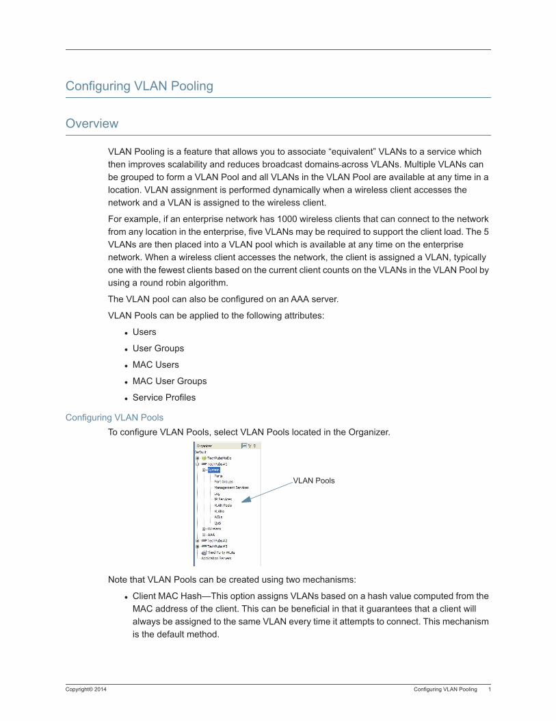
Copyright© 2014 Configuring VLAN Pooling 1
Configuring VLAN Pooling
Overview
VLAN Pooling is a feature that allows you to associate “equivalent” VLANs to a service which then improves scalability and reduces broadcast domains across VLANs. Multiple VLANs can be grouped to form a VLAN Pool and all VLANs in the VLAN Pool are available at any time in a location. VLAN assignment is performed dynamically when a wireless client accesses the network and a VLAN is assigned to the wireless client.
For example, if an enterprise network has 1000 wireless clients that can connect to the network from any location in the enterprise, five VLANs may be required to support the client load. The 5 VLANs are then placed into a VLAN pool which is available at any time on the enterprise network. When a wireless client accesses the network, the client is assigned a VLAN, typically one with the fewest clients based on the current client counts on the VLANs in the VLAN Pool by using a round robin algorithm.
The VLAN pool can also be configured on an AAA server.
VLAN Pools can be applied to the following attributes:
Users
User Groups
MAC Users
MAC User Groups
Service Profiles
Configuring VLAN PoolsTo configure VLAN Pools, select VLAN Pools located in the Organizer.
Note that VLAN Pools can be created using two mechanisms:
Client MAC Hash—This option assigns VLANs based on a hash value computed from the MAC address of the client. This can be beneficial in that it guarantees that a client will always be assigned to the same VLAN every time it attempts to connect. This mechanism is the default method.
VLAN Pools

2 Overview Copyright © 2014, Juniper Networks, Inc.
Load Balancing—With this option selected, the deployment will keep track of the total number of sessions supported by each VLAN in the domain. When a session gets assigned to the VLAN pool, the controller will direct the session to the VLAN that is under the least load at that time.
Once you select VLAN Pools, click Create VLAN Pools from the Task list. A configuration wizard allows you to add VLANs to VLAN Pools.
Copyright © 2014, Juniper Networks, Inc. Configuring Spanning Tree Properties 1
Configuring Spanning Tree Properties
The standard STP timers delay traffic forwarding briefly after a topology change. The time a port takes to change from the listening state to the learning state or from the learning state to the forwarding state is called the forwarding delay. In some configurations, this delay is unnecessary.
The WLC provides the following fast convergence features to bypass the forwarding delay:
Backbone fast convergence — Backbone fast convergence accelerates the recovery of a port following the failure of an indirect link. Normally, when a forwarding link fails, a bridge that is not directly connected to the link does not detect the link change until the maximum age timer expires. Backbone fast convergence enables the WLC to listen for bridge protocol data units (BPDUs) sent by a designated bridge when the designated link of a bridge to the root bridge fails, and immediately verifies whether BPDU information stored on a port is still valid. If the BPDU information on the port is no longer valid, the bridge immediately starts the listening stage on the port.
Uplink fast convergence — Uplink fast convergence enables a WLC that has redundant links to the network core to immediately change the state of a backup link to forwarding if the primary link to the root fails. Uplink fast convergence bypasses the listening and learning states to immediately enter the forwarding state.
1. From the Organizer panel, select a WLC.
2. Under System, select VLANs.
3. Under Spanning Tree Properties, you can select Enable Uplink Fast and Enable Backbone Fast.
Changing VLAN Spanning Tree SettingsThe purpose of the Spanning Tree Protocol (STP) is to maintain a loop-free network. A loop-free
path is accomplished when a device recognizes a loop in the topology and blocks one or more redundant paths. Mobility System Software (MSS) supports 802.1D and Per-VLAN Spanning Tree (PVST+) protocol.
MSS uses 802.1D bridge protocol data units (BPDUs) on VLAN ports that are untagged. However, each VLAN still runs its own instance of STP, even if two or more VLANs contain untagged ports. To run a single instance of STP in 802.1D mode on the entire WLC, configure all network ports as untagged members of the same VLAN.
Informational Note: If you plan to use the backbone fast convergence feature, enable it on all of the bridges in a spanning tree.
Informational Note: The uplink fast convergence feature is applicable to bridges that are acting as access WLCs to the network core (distribution layer) but are not in the core themselves. Do not enable the feature on WLCs that are in the network core.
2 Configuring Spanning Tree Properties Copyright © 2014, Juniper Networks, Inc.
MSS uses PVST+ BPDUs on VLAN ports that are tagged. PVST+ BPDUs include tag information in the 802.1Q field of the BPDUs. MSS runs a separate instance of PVST+ on each tagged VLAN.
To change the STP settings of a VLAN:
1. 1. Access the VLAN Properties multi-tabbed dialog box, then click on the Spanning Tree tab.
2. To enable STP, click Enabled.
3. Fill in the Instance Number field.In the Bridge Priority field, specify the priority of the STP bridge (0 to 65,535). The default is 32,768. The bridge with the lowest priority value becomes the root bridge for the spanning tree.
4. In the Protocol field, specify the maximum age value (6 to 40 seconds), which controls how long information from other bridges is kept. The default is 20 seconds.
5. In the Max Age field, specify the maximum age value (6 to 40 seconds), which controls how long information from other bridges is kept. The default is 20 seconds.
6. In the Hello Time field, specify the interval (1 to 10 seconds) between each configuration message from the root bridge. The default is 2 seconds.
7. In the Forward Delay field, specify the amount of time (4 to 30 seconds) a bridge waits after a topology change to begin forwarding data packets. The default is 15 seconds. Click OK.
Changing STP Port Settings in a VLAN
To change the STP Port settings of a VLAN:
1. Access the VLAN Properties multi-tabbed dialog box, then click on the Spanning Tree Ports tab.
2. To enable spanning tree packet processing (Tx/Rx) on that port, make sure Enabled is selected. This is the default. To disable this feature, clear Enabled. If you disable spanning tree packet processing on the port, the following might happen:
Informational Note: When you create a VLAN, STP is disabled on the new VLAN by default, regardless of the STP state of other VLANs on the WLCs.
Informational Note: IEEE 802.1D spanning tree specifications refer to networking devices that forward Layer 2 traffic as bridges. In this context, a WLC is a bridge. Where this manual or the product interface uses the term bridge, you can assume the term is applicable to the WLC.
Informational Note: This configures STP features for an individual VLAN but does not configure fast convergence features, which are global.
Copyright © 2014, Juniper Networks, Inc. Configuring Spanning Tree Properties 3
If STP is enabled on the VLAN, spanning tree packets are dropped at the port.
If STP is disabled on the VLAN, spanning tree packets are forwarded transparently through the VLAN to and from that port.
3. In the Port Priority field, specify a priority value (0 to 255). The default is 128.
4. In the Path Cost field, specify a value (0 to 65,535) for the cost. The default depends on the port speed and link type:
1000 Mbps, full duplex aggregate link (port group) — 19
1000 Mbps, full duplex — 4
100 Mbps, full duplex aggregate link (port group) — 19
100 Mbps, full duplex — 18
100 Mbps, half duplex — 19
10 Mbps, full duplex aggregate link (port group) — 19
10 Mbps, full duplex — 95
10 Mbps, half duplex — 100
Specify 0 to use the default cost for the port based on link speed.
5. To enable port fast convergence, select the Port Fast checkbox. Port fast convergence bypasses both the listening and learning stages and immediately places a port in the forwarding state. Use port fast convergence on network ports that are directly connected to servers, hosts, or other MAC stations.
Informational Note: Do not use port fast convergence on ports connected to other bridges.

4 Configuring Spanning Tree Properties Copyright © 2014, Juniper Networks, Inc.
Copyright © 2014, Juniper Networks, Inc. Configuring IGMP for VLANs 1
Configuring IGMP for VLANs
Internet Group Management Protocol (IGMP) snooping controls multicast traffic on a WLC by forwarding packets for a multicast group only on the ports that are connected to members of the group. IGMP is especially useful for WLANs because bandwidth is relatively constrained. The WLC listens for multicast packets and maintains a table of multicast groups, as well as their sources and receivers, based on the traffic. IGMP snooping is enabled by default.
You can configure IGMP snooping parameters and enable or disable the feature on an individual VLAN basis. The current software version supports IGMP versions 1 and 2.
To configure IGMP snooping:
1. Access the VLAN table:
a. Select the Configuration Navigation Bar button.
b. In the Organizer panel, click the plus sign next to a WLC.
c. Click the plus sign next to System.
d. Select VLANs.
2. Access the VLAN Properties multi-tabbed dialog box, then click on the IGMP tab.
3. To enable IGMP snooping, select Enable. To disable IGMP snooping, clear Enable. By default, IGMP snooping is enabled.
4. From the Version list, select Version 1 or Version 2 of IGMP.
5. If IGMP querier are not on the subnet (for example, multicast routers), select Querier Enabled. you should use the pseudo-querier only when a VLAN contains local multicast traffic that is not routed.
6. In the Query Interval field, specify the interval (1 to 65,535 seconds) at which the WLC sends general IGMP queries on behalf of multicast routers to advertise multicast groups. The default interval is 125 seconds.
7. In the Other Querier Present Interval field, specify how long (1 to 65,535 seconds) the WLC waits for a general query to arrive before making itself the querier. The default interval is 255 seconds.
8. In the Query Response Interval field, specify how long (1 to 65,535 tenths of a second) a device can take to respond to an IGMP query. The default interval is 100 tenths of a second (10 seconds).
9. In the Last Member Query Interval field, specify how long (1 to 65,535 tenths of a second) the WLC waits for a response to a group query, after receiving a leave message for that group, before removing the group. The default value is 10 tenths of a second (1 second).
10. In the Robustness Value field, specify the robustness value (2 to 255), which sets IGMP timers to adjust to the amount of traffic loss on the network. Set the robustness value higher to adjust for more traffic loss. The default is 2.
11. To enable proxy reporting, which summarizes collected station IGMP reports, select Proxy Report.

2 Configuring IGMP for VLANs Copyright © 2014, Juniper Networks, Inc.
12. To enable multicast router solicitation, which allows a WLC to discover multicast routers on the subnet, select Multicast Router Solicitation.
13. In the Solicitation Interval field, specify the interval (1 to 65,535 seconds) between multicast router solicitations by a WLC. The default interval is 30 seconds.
14. Click OK.
Copyright © 2014, Juniper Networks, Inc. Configuring Static Multicast Ports 1
Configuring Static Multicast Ports
A WLC learns about multicast routers and receivers from multicast traffic received from those devices. When the WLC receives traffic from a multicast router or receiver, the WLC adds the port that received the traffic as a multicast router or receiver port. The WLC forwards traffic to multicast routers only on the multicast router ports and forwards traffic to multicast receivers only on the multicast receiver ports.
The router and receiver ports that the WLC learns based on multicast traffic age out if they are unused. If necessary, you can statically configure multicast router ports or multicast receiver ports on the WLC.
You can only add network ports as static multicast router ports or multicast receiver ports. Ports you add are immediately added to the list and do not age out.
To add or remove static multicast router and receiver ports:
1. Access the VLAN table:
a. Select the Configuration Navigation Bar button.
b. In the Organizer panel, click the plus sign next to a WLC.
c. Click the plus sign next to System.
d. Select VLANs.
2. In the Content panel, select a VLAN.
3. Click Properties.
4. Access the VLAN Properties multi-tabbed dialog box, then click on the VLAN Member Details tab.
5. To add a static multicast receiver port, select the Forward Multicast IP Out checkbox for each port you want to add. By default, ports are not selected. To remove a static multicast receiver port, clear the checkbox.
6. To add a multicast router port, click in the Multicast Router Present checkbox for each port you want added. By default, ports are not selected. To remove a static multicast receiver port, clear the checkbox.
Click OK.
Informational Note: You cannot add MP ports or wired authentication ports as static multicast ports. However, MSS can dynamically add these port types to the list of multicast ports based on multicast traffic.

2 Configuring Static Multicast Ports Copyright © 2014, Juniper Networks, Inc.
Copyright © 2014, Juniper Networks, Inc. Restricting Layer 2 Traffic Among Clients in a VLAN 1
Restricting Layer 2 Traffic Among Clients in a VLAN
By default, clients within a VLAN are able to communicate with one another directly at Layer 2. You can enhance network security by restricting Layer 2 forwarding among clients in the same VLAN. When you restrict Layer 2 forwarding in a VLAN, MSS allows Layer 2 forwarding only between a client and a set of MAC addresses, generally the default routers (gateways) of a VLAN.
Clients within the VLAN are not permitted to communicate among themselves directly. To communicate with another client, the client must use one of the specified default routers. You can specify up to four default router MAC addresses. The addresses must be unicast (not multicast or broadcast).
1. Access the VLAN table:
a. Select the Configuration Navigation Bar button.
b. In the Organizer panel, click the plus sign next to a WLC.
c. Click the plus sign next to System.
d. Select VLANs.
2. In the Content panel, select a VLAN.
3. Access the VLAN Properties multi-tabbed dialog box, then click on the VLAN L2Restriction tab.
4. Select Restrict L2 Traffic to enable the feature for a VLAN.
5. Click Create.
6. In the MAC Address field, edit the address to be the MAC address of the default router (gateway) of a VLAN.
7. Click Finish.
Informational Note: For networks with IP-only clients, you can restrict client-to-client forwarding using Access Control Lists (ACLs). Use the Restrict L3 Traffic option.

2 Restricting Layer 2 Traffic Among Clients in a VLAN Copyright © 2014, Juniper Networks, Inc.
Copyright © 2014, Juniper Networks, Inc. Configuring IP Security Destinations 1
Configuring IP Security Destinations
IPSec is a general purpose Internet security protocol, and can used for protecting Layer 4 network protocols including both TCP and UDP. IPSEc has an advantage over SSL and other methods because the application does not have to be designed to use IPSec like other higher-layer protocols that must be incorporated into the design of an application.
To configure IP Security Destinations, follow these steps:
1. In the Task List, under Setup, click IP Security Destinations. This displays the IP Security Destination wizard.
2. To enable IP Security Destinations, select Enable.
3. In the Destination field, enter the IP address of the interface.
4. Enter a value for the SPI.
5. Select the type of Encryption Algorithm, either 3DES-CBC (triple Data Encryption Standard - Cipher Block Chaining) (less secure) or AES-CBC (Authentication Encryption Standard - Cipher Block Chaining) (more secure).
6. Enter the Encryption Key value. The default value is none, and you can use up to 24 hexadecimal characters.
7. Select HMAC-SHA1 (Hash-based Message Authentication Code - Secure Hash Authentication 1) as the Authentication Algorithm.
8. Enter the Authentication Key. The default is none, but you can use up to 20 hexadecimal characters.
9. Click OK to save the configuration.

2 Configuring IP Security Destinations Copyright © 2014, Juniper Networks, Inc.
Copyright © 2014, Juniper Networks, Inc. Restricting Layer 3 Traffic Among Clients in a VLAN 1
Restricting Layer 3 Traffic Among Clients in a VLAN
To restrict Layer 3 traffic among clients in the same VLAN, use an ACL. You can configure the ACL yourself or use the Restrict L3 Traffic option in RingMaster.
1. Access the VLAN table:
a. Select the Configuration Navigation Bar button.
b. In the Organizer panel, click the plus sign next to a WLC.
c. Click the plus sign next to System.
d. Select VLANs.
2. In the Content panel, select a VLAN.
3. In the Tasks panel, select Restrict L3 Traffic.
4. Type the IP address of the default router (gateway) of a VLAN. Click Next.
5. The configured ACL block L3 traffic and is displayed. Click Finish.

2 Restricting Layer 3 Traffic Among Clients in a VLAN Copyright © 2014, Juniper Networks, Inc.
Copyright © 2014, Juniper Networks, Inc. Configuring the DHCP Server 1
Configuring the DHCP Server
MSS has a Dynamic Host Configuration Protocol (DHCP) server that the WLC uses to allocate IP addresses to the following components. DHCP service for these items is enabled by default.
Directly connected WLAs
Host connected to a new (unconfigured) WLC2, WLC8, WLC200, or WLC216, to configure the WLC using the Web Quick Start
Optionally, you can configure the DHCP server to also provide IP addresses to Distributed WLAs
and to clients.
To enable the MSS DHCP server on a VLAN:
1. Access the VLAN table:
a. Select the Configuration Navigation Bar button.
b. In the Organizer panel, click the plus sign next to a WLC.
c. Click the plus sign next to System.
d. Select VLANs.
2. In the Content panel, select a VLAN.
3. Click Properties.
4. Access the VLAN Properties multi-tabbed dialog box, then click on the DHCP Server tab.
5. Select DHCP Server to enable it on a VLAN.
6. 6. To change the range of addresses available to a DHCP server, edit addresses in the Start IP Addresses and Stop IP Addresses fields. By default, all addresses except the host address of the VLAN, the network broadcast address, and the subnet broadcast address are included in the range. If you specify the range, the start address must be lower than the stop address, and all addresses must be in the same subnet. The IP interface of the VLAN must be within the same subnet but is not required to be within the range.
7. In the Primary DNS IP Address field, enter the IP address of the primary DNS server for clients who receive addresses from this VLAN.
8. To provide a backup DNS server, type the server IP address in the Secondary DNS IP Address field.
9. To specify the DNS domain name for hosts who receive IP addresses from this VLAN, enter the domain name in the DNS Name field.
10. To specify the default router (gateway) for hosts who receive IP addresses from this VLAN, enter the address in the Default Gateway IP Address field. Click OK.
Caution: Use of the MSS DHCP server to allocate client addresses is intended for temporary, demonstration deployments and not for production networks. We recommend you do not use the MSS DHCP server to allocate client addresses in a production network.

2 Configuring the DHCP Server Copyright © 2014, Juniper Networks, Inc.
Copyright © 2014, Juniper Networks, Inc. Changing the Aging Time for FDB Entries 1
Changing the Aging Time for FDB Entries
The aging timeout period specifies how long a dynamic entry can remain inactive before MSS removes the entry from the database.
1. Access the VLAN table:
a. Select the Configuration Navigation Bar button.
b. In the Organizer panel, click the plus sign next to a WLC.
c. Click the plus sign next to System.
d. Select VLANs.
2. In the Content panel, select a VLAN.
3. Click Properties
4. In the Aging Time field, specify the aging timeout period (0to 1,000,000 seconds) for dynamic entries in the forwarding database. The default is 300 seconds (5 minutes). If you specify 0, aging is disabled.
5. Click OK.

2 Changing the Aging Time for FDB Entries Copyright © 2014, Juniper Networks, Inc.
Copyright © 2014, Juniper Networks, Inc. Overview of Access Control Lists (ACLs) 1
Overview of Access Control Lists (ACLs)
Access Control Lists (ACLs) filter packets to restrict or permit network usage by certain users, network devices, or traffic types. You can also assign a Class of Service (CoS) level, which allows priority handling, to packets. For example, you can use ACLs to enable users to send and receive packets within an Intranet, but restrict incoming packets to the server that stores confidential salary information.
An ACL is an ordered list of Access Control Entries (ACEs) — rules that specify how to handle packets. A rule includes a filter and an action. When a packet matches a filter, a specific action is applied to the packet. If there are no ACE matches in an ACL, it contains an implicit rule that denies all access. If there is not at least one ACE that permits access in an ACL, no traffic is allowed. The implicit “deny all” rule is always the last ACE of an ACL.
You can choose to count the number of times an ACE is matched. This hit count is useful for troubleshooting complex ACL configurations and for monitoring traffic load for specific network applications or protocols. The hit count can only be seen from the CLI. To start updating hit counter statistics in the CLI, you must first set the hits sampling rate to a nonzero value, such as 15 seconds.
You cannot perform ACL functions that include permitting, denying, or marking with a Class of Service (CoS) level on packets with a multicast or broadcast destination address.
MAC-based ACLsAccess Control Lists (ACLs) filter packets based on certain fields in the packet such as ICMP, IP address, TCP, CoS or UDP. You can also configure ACLs using MAC addresses. The MAC address mask is similar to IP address masks, but specified in hexadecimal format.
IPv6 ACLsIPv6 addresses can also be used for creating ACLs based on IP addresses. Configuring IPv6 addresses is not supported, but IPv6 clients are supported. The WLC can view IPv6 session information and control IPv6 ACLs. The session information now includes:
IPv6 information of both dual-stack and IPv6 only clients.
16 of the most recent IPv6 addresses plus one local link address of a client.
For dual stack clients, the IPv4 session is kept for storing IPv6 addresses.
.IPv6 and ACLsPreviously, MSS only supported Layer 2 ACLs for IPv6. This has expanded with the release of MSS 8.0 and later to support:
Source IPv6 addresses
Destination IPv6 addresses
Port
Types including ICMP, TCP, and UDP
The IPv6 ACLs are differentiated from IPv4 ALCs by using the keyword, ipv6.

2 Overview of Access Control Lists (ACLs) Copyright © 2011, Juniper Networks, Inc.
Copyright © 2014, Juniper Networks, Inc. Creating an Access Control List (ACL) 1
Creating an Access Control List (ACL)
The Create ACL wizard enables you to configure ACEs with the following parameters:
Source IP address
Destination IP address
Protocol - Source protocol port
Destination protocol port
Differentiated Services Code Point (DSCP) value or Type Of Service (TOS) and IP Precedence values
Action: deny or permit
Marking: Class of Service (CoS) value
These parameters are sufficient for most ACEs. To configure additional parameters, use the wizard to configure the basic parameters, then select the ACE and click Properties. (See Configuring Advanced ACL Settings.)
1. From the Organizer panel, select a WLC.
2. Under System, select ACLs.
3. Under Create, click Create ACL.
4. Enter a unique name for the ACL.
In the ACL Name field, type the name for the ACL (1 to 32 alphanumeric characters, with no spaces or tabs). The name can include hyphens (-), underscores (_), or periods (.). ACL names are case-sensitive and must begin with a letter. Do not include any of the following terms in the name: all, default-action, map, help, editbuffer.
Adding a MAC Based Rule
To add a MAC based rule, follow these steps:
5. Click Add MAC Based Rule. The MAC Based Rules list is populated with default values.
6. To change the Source MAC from the default value of Any, click the arrow to display Source MAC Details. From the Source MAC Name list, select from Any or Other. If you select Other, enter the MAC address in the Source MAC Address field. Click OK.
7. Repeat Step 6 for the Destination MAC field.
8. To change the Ethertype, click the arrow to display Ethertype Details. From the Ethertype name list, you can select from Any, ARP, IPv4, IPv6, or Other. Click OK to close the window.
9. Select Permit or Deny from the Action list.
10. Adjust the CoS value if necessary.
Informational Note: Any ACL that refers to a DAP can be configured on the seed only as it references domain configuration. ACLs with mappings to ports, vports, and VLANs can be defined at member WLCs as well. If an ACL with the same name is defined in both the domain configuration and on a member WLC local configuration, the ACL from the WLC configuration is applied.
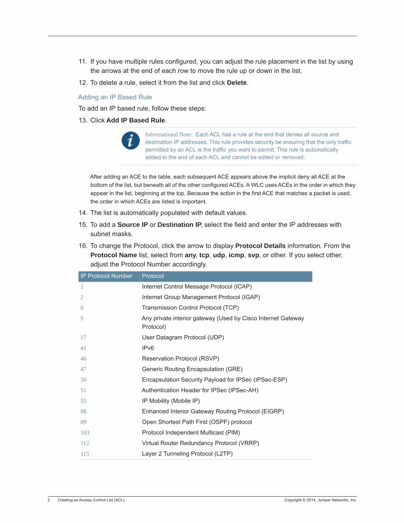
2 Creating an Access Control List (ACL) Copyright © 2014, Juniper Networks, Inc.
11. If you have multiple rules configured, you can adjust the rule placement in the list by using the arrows at the end of each row to move the rule up or down in the list.
12. To delete a rule, select it from the list and click Delete.
Adding an IP Based Rule
To add an IP based rule, follow these steps:
13. Click Add IP Based Rule.
After adding an ACE to the table, each subsequent ACE appears above the implicit deny all ACE at the bottom of the list, but beneath all of the other configured ACEs. A WLC uses ACEs in the order in which they appear in the list, beginning at the top. Because the action in the first ACE that matches a packet is used, the order in which ACEs are listed is important.
14. The list is automatically populated with default values.
15. To add a Source IP or Destination IP, select the field and enter the IP addresses with subnet masks.
16. To change the Protocol, click the arrow to display Protocol Details information. From the Protocol Name list, select from any, tcp, udp, icmp, svp, or other. If you select other, adjust the Protocol Number accordingly.
Informational Note: Each ACL has a rule at the end that denies all source and destination IP addresses. This rule provides security be ensuring that the only traffic permitted by an ACL is the traffic you want to permit. This rule is automatically added to the end of each ACL and cannot be edited or removed.
IP Protocol Number Protocol
1 Internet Control Message Protocol (ICAP)
2 Internet Group Management Protocol (IGAP)
6 Transmission Control Protocol (TCP)
9 Any private interior gateway (Used by Cisco Internet Gateway Protocol)
17 User Datagram Protocol (UDP)
41 IPv6
46 Reservation Protocol (RSVP)
47 Generic Routing Encapsulation (GRE)
50 Encapsulation Security Payload for IPSec (IPSec-ESP)
51 Authentication Header for IPSec (IPSec-AH)
55 IP Mobility (Mobile IP)
88 Enhanced Interior Gateway Routing Protocol (EIGRP)
89 Open Shortest Path First (OSPF) protocol
103 Protocol Independent Multicast (PIM)
112 Virtual Router Redundancy Protocol (VRRP)
115 Layer 2 Tunneling Protocol (L2TP)
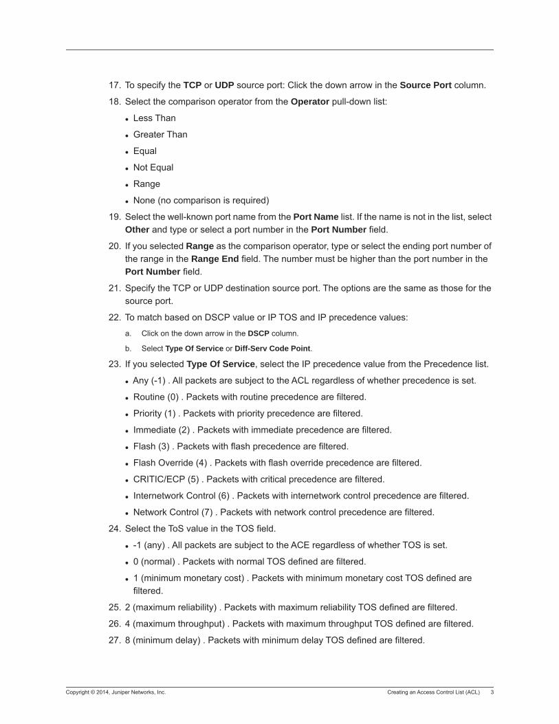
Copyright © 2014, Juniper Networks, Inc. Creating an Access Control List (ACL) 3
17. To specify the TCP or UDP source port: Click the down arrow in the Source Port column.
18. Select the comparison operator from the Operator pull-down list:
Less Than
Greater Than
Equal
Not Equal
Range
None (no comparison is required)
19. Select the well-known port name from the Port Name list. If the name is not in the list, select Other and type or select a port number in the Port Number field.
20. If you selected Range as the comparison operator, type or select the ending port number of the range in the Range End field. The number must be higher than the port number in the Port Number field.
21. Specify the TCP or UDP destination source port. The options are the same as those for the source port.
22. To match based on DSCP value or IP TOS and IP precedence values:
a. Click on the down arrow in the DSCP column.
b. Select Type Of Service or Diff-Serv Code Point.
23. If you selected Type Of Service, select the IP precedence value from the Precedence list.
Any (-1) . All packets are subject to the ACL regardless of whether precedence is set.
Routine (0) . Packets with routine precedence are filtered.
Priority (1) . Packets with priority precedence are filtered.
Immediate (2) . Packets with immediate precedence are filtered.
Flash (3) . Packets with flash precedence are filtered.
Flash Override (4) . Packets with flash override precedence are filtered.
CRITIC/ECP (5) . Packets with critical precedence are filtered.
Internetwork Control (6) . Packets with internetwork control precedence are filtered.
Network Control (7) . Packets with network control precedence are filtered.
24. Select the ToS value in the TOS field.
-1 (any) . All packets are subject to the ACE regardless of whether TOS is set.
0 (normal) . Packets with normal TOS defined are filtered.
1 (minimum monetary cost) . Packets with minimum monetary cost TOS defined are filtered.
25. 2 (maximum reliability) . Packets with maximum reliability TOS defined are filtered.
26. 4 (maximum throughput) . Packets with maximum throughput TOS defined are filtered.
27. 8 (minimum delay) . Packets with minimum delay TOS defined are filtered.
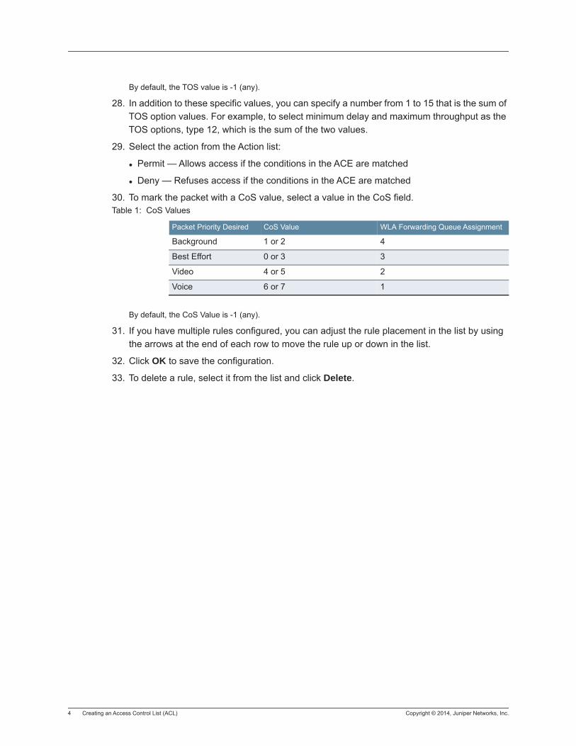
4 Creating an Access Control List (ACL) Copyright © 2014, Juniper Networks, Inc.
By default, the TOS value is -1 (any).
28. In addition to these specific values, you can specify a number from 1 to 15 that is the sum of TOS option values. For example, to select minimum delay and maximum throughput as the TOS options, type 12, which is the sum of the two values.
29. Select the action from the Action list:
Permit — Allows access if the conditions in the ACE are matched
Deny — Refuses access if the conditions in the ACE are matched
30. To mark the packet with a CoS value, select a value in the CoS field.
By default, the CoS Value is -1 (any).
31. If you have multiple rules configured, you can adjust the rule placement in the list by using the arrows at the end of each row to move the rule up or down in the list.
32. Click OK to save the configuration.
33. To delete a rule, select it from the list and click Delete.
Table 1: CoS Values
Packet Priority Desired CoS Value WLA Forwarding Queue Assignment
Background 1 or 2 4
Best Effort 0 or 3 3
Video 4 or 5 2
Voice 6 or 7 1
Copyright © 2014, Juniper Networks, Inc. Editing an Access Control List (ACL) Rules for an Existing Rule 1
Editing an Access Control List (ACL) Rules for an Existing Rule
1. From the Organizer panel, select a WLC.
2. Under System, select ACLs.
3. Select an ACL from the ACL Rules list.
4. Under Setup, click ACL Rules for “rulename” where rulename is a previously configured ACL.
5. Follow the steps in Create ACL to change the configuration.

2 Editing an Access Control List (ACL) Rules for an Existing Rule Copyright © 2011, Juniper Networks, Inc.
Copyright © 2014, Juniper Networks, Inc. Editing an Access Control List (ACL) Hit Sample Rate 1
Editing an Access Control List (ACL) Hit Sample Rate
1. From the Organizer panel, select a WLC.
2. Under System, select ACLs.
3. Under Other, click Edit ACL Hit Sample Rate.
4. Adjust the Hit Sample Rate in seconds for access rules hits. Leaving the value at 0 disables the sampling rate. You can select from a range of 0 (disabled) to 100 seconds.
5. Click OK to save the configuration.

2 Editing an Access Control List (ACL) Hit Sample Rate Copyright © 2014, Juniper Networks, Inc.
Copyright © 2014, Juniper Networks, Inc. Mapping an ACL 1
Mapping an ACL
An ACL does not take effect until you map it to a user or an interface. You can map ACLs to ports (or port groups), VLANs, or virtual ports. You cannot map an ACL to a WLA port or a wired authentication port. You can map ACLs to users by configuring the filter.in and filter.out user attributes. User-based ACLs are more specific than ACLs applied to interfaces and are therefore processed first.
1. From the Organizer panel, select a WLC.
2. Under System, select ACLs.
3. Select an ACL from the ACL Rules list.
4. Under Setup, click ACL Rules for “rulename” where rulename is a previously configured ACL.
5. Click ACL Mappings for “rulename”.
6. Select the mapping type:
To map to a physical port, select port and go to step 5.
To map to a virtual port, select vport and go to step 6.
To map to a VLAN, select vlan and go to step 7.
To map to a Distributed WLA, select distributed ap and go to step 8.
Mapping an ACL to a Port
7. To map an ACL to a port:
a. In the Port list, select a port or port group to which you want to map the ACL. You cannot map an ACL to a WLA port or a wired authentication port.
b. In the Direction list, select In to filter incoming packets or Out to filter outgoing packets.
8. Click Finish.
Mapping an ACL to a Virtual Port
9. To map an ACL to a virtual port:
a. In the Tag Value field, specify the 802.1Q tag value that identifies a virtual port in a VLAN. The tag value can be a number from 1 to 4093. The default value is 1. Make sure that you do not specify duplicate mappings that specify the same port and tag value.
b. In the Port list, select the port to which you want to map the ACL. You cannot map an ACL to a WLA port or a wired authentication port.
c. In the Direction list, select In to filter incoming packets or Out to filter outgoing packets.
Mapping an ACL to a VLAN
10. To map an ACL to a VLAN:
a. In the Type list, select ID to identify the VLAN by number or Name to identify it by name.
b. If you selected Name, select or type the VLAN name from the Name list.
c. If you selected ID, select or type the VLAN number in the ID field.

2 Mapping an ACL Copyright © 2014, Juniper Networks, Inc.
Mapping ACL to a Distributed WLA
11. To map an ACL to a Distributed WLA:
a. In the WLA ID list, select a Distributed WLA.
b. In the Direction list, select In to filter incoming packets or Out to filter outgoing packets.
Copyright © 2014, Juniper Networks, Inc. Configuring Advanced ACL Settings 1
Configuring Advanced ACL Settings
After configuring an ACL, configure the following advanced settings:
Hit counter (enable or disable)
Hit sample rate (applies if the hit counter is enabled)
Established option, to apply a new TCP ACE only to established (existing) TCP sessions. By default, TCP ACEs apply to new sessions as well as existing ones.
ICAP properties, to specify the type and code values for ICAP ports (applies only to ACEs that have ICAP as the protocol)
Capture option, to redirect matching packets to the CPU (applies to ACEs used for Web Portal access)
Hit Sample RateThe hit sample rate specifies the time interval, in seconds, at which the packet counter is sampled for each security ACE on which the hit counter is enabled. By default, the hit sample rate is 0, even when the hit counter is enabled. To use the hit counter, you must enable it and set the hit sample rate. The hit sample rate applies globally to all ACEs on which the hit counter is enabled.
To change the hit sample rate:
1. From the Organizer panel, select a WLC.
2. Under System, select ACLs.
3. Under Other, click Edit ACL Hit Sample Rate.
4. Adjust the Hit Sample Rate in seconds for access rules hits. Leaving the value at 0 disables the sampling rate. You can select from a range of 0 (disabled) to 100 seconds.
5. You can enable the hit counter on an individual ACE basis.To enable the hit counter for an ACE:
a. Select the ACE in the ACL table.
b. In the Tasks panel, select Enable Hits for this rule.
By default, a new TCP ACE applies to new sessions as well as established (existing) sessions. To apply the ACE only to established sessions, enable the established option.
To enable the established option for TCP ACEs:
1. Select a TCP ACE in the ACL table.
2. In the Tasks panel, select Enable Established Connections.
To specify the type and code for ICAP ACEs:
Select a ICAP ACE in the ACL table.
1. In the Tasks panel, select ICAP Properties.
2. Select or type the ICAP message type in the Type field.Select or type the ICAP message code in the Code field.
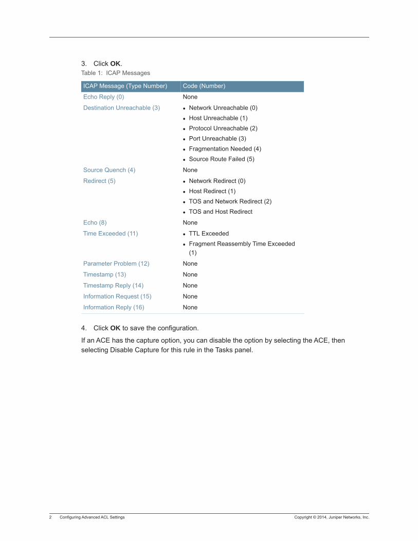
2 Configuring Advanced ACL Settings Copyright © 2014, Juniper Networks, Inc.
3. Click OK.
4. Click OK to save the configuration.
If an ACE has the capture option, you can disable the option by selecting the ACE, then selecting Disable Capture for this rule in the Tasks panel.
Table 1: ICAP Messages
ICAP Message (Type Number) Code (Number)
Echo Reply (0) None
Destination Unreachable (3) Network Unreachable (0)
Host Unreachable (1)
Protocol Unreachable (2)
Port Unreachable (3)
Fragmentation Needed (4)
Source Route Failed (5)
Source Quench (4) None
Redirect (5) Network Redirect (0)
Host Redirect (1)
TOS and Network Redirect (2)
TOS and Host Redirect
Echo (8) None
Time Exceeded (11) TTL Exceeded
Fragment Reassembly Time Exceeded (1)
Parameter Problem (12) None
Timestamp (13) None
Timestamp Reply (14) None
Information Request (15) None
Information Reply (16) None
Copyright © 2014, Juniper Networks, Inc. Deleting an ACL 1
Deleting an ACL
1. From the Organizer panel, select a WLC.
2. Under System, select ACLs.
3. Select an ACE in an ACL that you want to delete.
4. In the Tasks panel, click Delete.
5. Verify the selection and click Finish.
Deleting an Individual ACE from an ACL1. From the Organizer panel, select a WLC.
2. Under System, select ACLs.
3. Select an ACE in an ACL that you want to delete.
4. In the Tasks panel, click Delete.
5. Verify the selection and click Finish.

2 Deleting an ACL Copyright © 2014, Juniper Networks, Inc.
Copyright © 2014, Juniper Networks, Inc. Creating a Quality of Service (QoS) Profile 1
Creating a Quality of Service (QoS) Profile
1. From the Organizer panel, select a WLC.
2. Under System, select QoS.
3. In the Tasks panel, click Create QoS Profile.
4. Enter a QoS Profile Name and click Next.
Sessions QoS Profile Settings
5. You can use the checkbox to enforce and select a bandwidth limit, and to enable and assign a value to a CoS value. To enable static CoS, select Enable Static CoS. To enable DSCP for upstream packet classification, select Trust Client DSCP.
6. Click Next.
Flow-based QoS Profile Settings
7. Enable SIP Awareness by selecting voip-data from the Traffic Class list.
Integrated SIP awareness in a wireless network adds a new level of intelligence that allows granular and dynamic control of voice applications between wireless, wired infrastructure, and wireless handsets as well as wireless clients in the area of security and system resource management.
8. You can use the checkbox to enforce and select a bandwidth limit, and to enable and assign a value to a CoS value. To enable static CoS, select Enable Static CoS.
9. Click Next.
QoS Profile Mapping
You can add authorization attributes such as users, user groups, MAC user groups, or SSIDs.
10. Select a Named User from the list.
11. Select a User MAC Address.
12. Select a Named User Group.
13. Select a MAC User Group.
14. Select an SSID.
15. You can also map this profile to a Location Policy by selecting Map to a Location Policy.
16. Click Next.
Location Policy Rules
17. From the list of available Location Policies, select one and click Finish. If you want to check the properties of the policy, click Properties.

2 Creating a Quality of Service (QoS) Profile Copyright © 2014, Juniper Networks, Inc.
Copyright © 2014, Juniper Networks, Inc. Setting Up DSCP to CoS Mapping 1
Setting Up DSCP to CoS Mapping
MSS supports Layer 2 and Layer 3 classification and marking of traffic, to help provide end-to-end Quality of Service (QoS) throughout a network. QoS support includes support of Wi-Fi Multimedia (WMM), which provides wireless QoS for time-sensitive applications such as voice and video.
QoS support is automatically enabled. WLCs and WLA access points each provide QoS:
WLCs classify and mark traffic based on 802.1p tag value (for tagged traffic) or Differentiated Services Code Point (DSCP) value.
WLA access points classify ingress traffic from wireless clients based on the service type value in the 802.11 header, and mark the DSCP value in the IP tunnel on which the WLA forwards the user traffic to the WLC.
WLAs place traffic from a WLC to a wireless client in a forwarding queue based on the DSCP value in the tunnel carrying the traffic, then forward the traffic based on the priority.
MSS performs classification on ingress to determine the CoS value. This CoS value is used to mark the packet at the egress interface. Classification and marking performed by a WLC depend on whether the ingress interface has an 802.1p or DSCP value other than 0, and whether the egress interface is tagged or is an IP tunnel. The mappings between DSCP and CoS values are configurable.
1. From the Organizer panel, select a WLC.
2. Under System, select QoS.
3. In the Tasks panel, under Setup, click DSCP to CoS Mapping.
4. The QoS window displays the DSCP to CoS and CoS to DSCP mapping tables.
5. In the DSCP to CoS table, change the CoS value using the up and down arrows at the end of the row.
6. In the CoS to DSCP table, change the DSCP value using the up and down arrows at the end of the row.
7. Under Setup, you can reset the values to default values or set the DSCP to CoS range. To configure the DSCP Range, click Set DSCP to CoS Range.
8. Set the first and last DSCP value as well as the CoS value. Click Finish to save the configuration.

2 Setting Up DSCP to CoS Mapping Copyright © 2014, Juniper Networks, Inc.
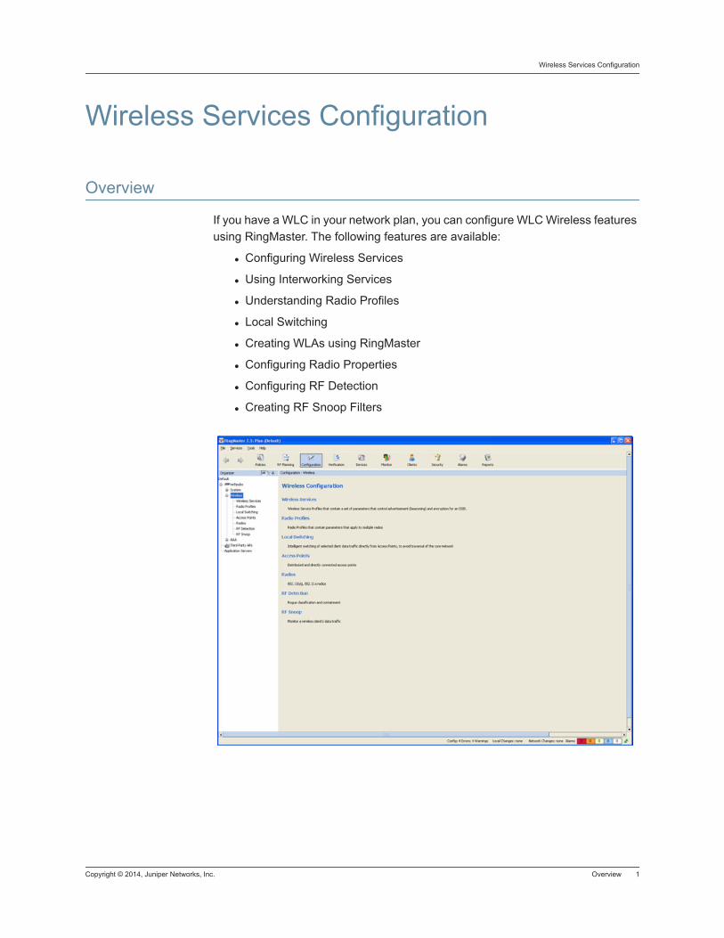
Copyright © 2014, Juniper Networks, Inc. Overview 1
Wireless Services Configuration
Wireless Services Configuration
Overview
If you have a WLC in your network plan, you can configure WLC Wireless features using RingMaster. The following features are available:
Configuring Wireless Services
Using Interworking Services
Understanding Radio Profiles
Local Switching
Creating WLAs using RingMaster
Configuring Radio Properties
Configuring RF Detection
Creating RF Snoop Filters

2 Overview Copyright © 2014, Juniper Networks, Inc.
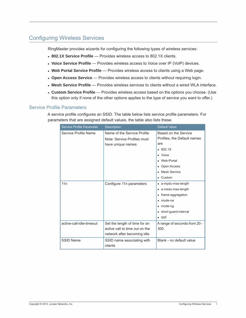
Copyright © 2014, Juniper Networks, Inc. Configuring Wireless Services 1
Configuring Wireless Services
RingMaster provides wizards for configuring the following types of wireless services:
802.1X Service Profile — Provides wireless access to 802.1X clients.
Voice Service Profile — Provides wireless access to Voice over IP (VoIP) devices.
Web Portal Service Profile — Provides wireless access to clients using a Web page.
Open Access Service — Provides wireless access to clients without requiring login.
Mesh Service Profile — Provides wireless services to clients without a wired WLA interface.
Custom Service Profile — Provides wireless access based on the options you choose. (Use this option only if none of the other options applies to the type of service you want to offer.)
Service Profile ParametersA service profile configures an SSID. The table below lists service profile parameters. For parameters that are assigned default values, the table also lists these.
Service Profile Parameter Description Default Value
Service Profile Name Name of the Service Profile
Note: Service Profiles must have unique names.
Based on the Service Profiles, the Default names are
802.1X
Voice
Web-Portal
Open Access
Mesh Service
Custom
11n Configure 11n parameters a-mpdu-max-length
a-msdu-max-length
frame-aggregation
mode-na
mode-ng
short-guard-interval
txbf
active-call-idle-timeout Set the length of time for an active call to time out on the network after becoming idle.
A range of seconds from 20 - 300.
SSID Name SSID name associating with clients
Blank - no default value
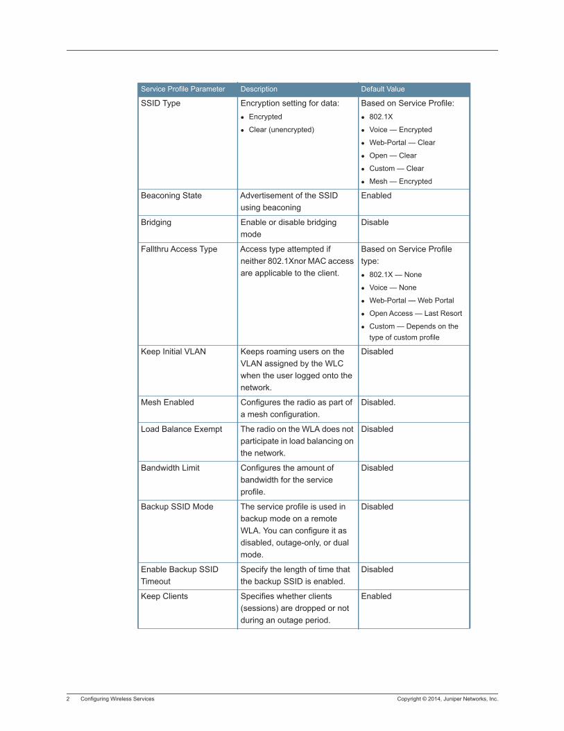
2 Configuring Wireless Services Copyright © 2014, Juniper Networks, Inc.
SSID Type Encryption setting for data:Encrypted
Clear (unencrypted)
Based on Service Profile:802.1X
Voice — Encrypted
Web-Portal — Clear
Open — Clear
Custom — Clear
Mesh — Encrypted
Beaconing State Advertisement of the SSID using beaconing
Enabled
Bridging Enable or disable bridging mode
Disable
Fallthru Access Type Access type attempted if neither 802.1Xnor MAC access are applicable to the client.
Based on Service Profile type:
802.1X — None
Voice — None
Web-Portal — Web Portal
Open Access — Last Resort
Custom — Depends on the type of custom profile
Keep Initial VLAN Keeps roaming users on the VLAN assigned by the WLC when the user logged onto the network.
Disabled
Mesh Enabled Configures the radio as part of a mesh configuration.
Disabled.
Load Balance Exempt The radio on the WLA does not participate in load balancing on the network.
Disabled
Bandwidth Limit Configures the amount of bandwidth for the service profile.
Disabled
Backup SSID Mode The service profile is used in backup mode on a remote WLA. You can configure it as disabled, outage-only, or dual mode.
Disabled
Enable Backup SSID Timeout
Specify the length of time that the backup SSID is enabled.
Disabled
Keep Clients Specifies whether clients (sessions) are dropped or not during an outage period.
Enabled
Service Profile Parameter Description Default Value
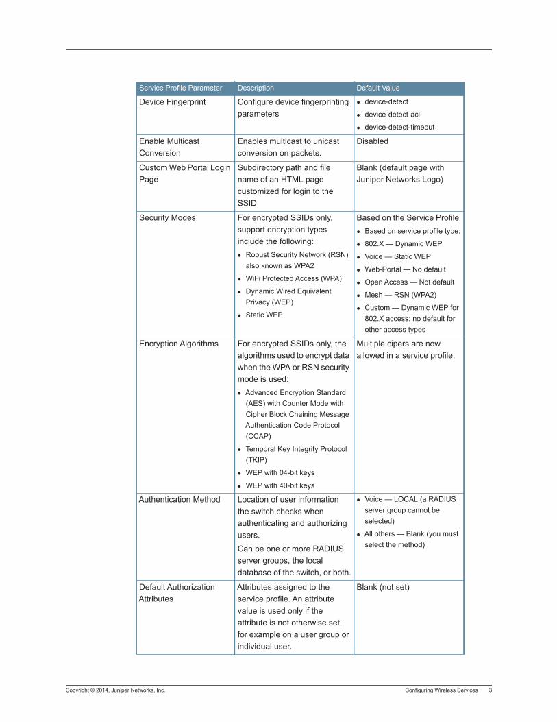
Copyright © 2014, Juniper Networks, Inc. Configuring Wireless Services 3
Device Fingerprint Configure device fingerprinting parameters
device-detect
device-detect-acl
device-detect-timeout
Enable Multicast Conversion
Enables multicast to unicast conversion on packets.
Disabled
Custom Web Portal Login Page
Subdirectory path and file name of an HTML page customized for login to the SSID
Blank (default page with Juniper Networks Logo)
Security Modes For encrypted SSIDs only, support encryption types include the following:
Robust Security Network (RSN) also known as WPA2
WiFi Protected Access (WPA)
Dynamic Wired Equivalent Privacy (WEP)
Static WEP
Based on the Service Profile Based on service profile type:
802.X — Dynamic WEP
Voice — Static WEP
Web-Portal — No default
Open Access — Not default
Mesh — RSN (WPA2)
Custom — Dynamic WEP for 802.X access; no default for other access types
Encryption Algorithms For encrypted SSIDs only, the algorithms used to encrypt data when the WPA or RSN security mode is used:
Advanced Encryption Standard (AES) with Counter Mode with Cipher Block Chaining Message Authentication Code Protocol (CCAP)
Temporal Key Integrity Protocol (TKIP)
WEP with 04-bit keys
WEP with 40-bit keys
Multiple cipers are now allowed in a service profile.
Authentication Method Location of user information the switch checks when authenticating and authorizing users.
Can be one or more RADIUS server groups, the local database of the switch, or both.
Voice — LOCAL (a RADIUS server group cannot be selected)
All others — Blank (you must select the method)
Default Authorization Attributes
Attributes assigned to the service profile. An attribute value is used only if the attribute is not otherwise set, for example on a user group or individual user.
Blank (not set)
Service Profile Parameter Description Default Value
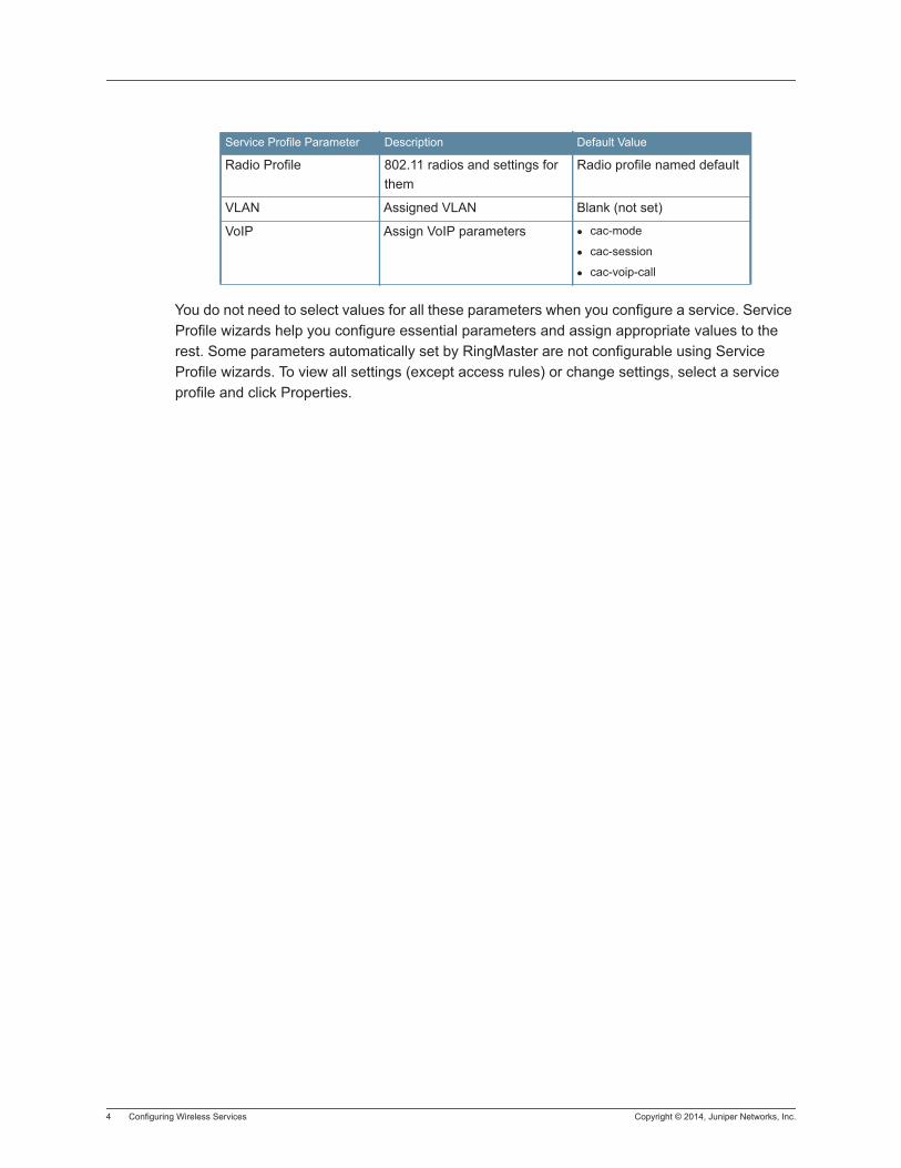
4 Configuring Wireless Services Copyright © 2014, Juniper Networks, Inc.
You do not need to select values for all these parameters when you configure a service. Service Profile wizards help you configure essential parameters and assign appropriate values to the rest. Some parameters automatically set by RingMaster are not configurable using Service Profile wizards. To view all settings (except access rules) or change settings, select a service profile and click Properties.
Radio Profile 802.11 radios and settings for them
Radio profile named default
VLAN Assigned VLAN Blank (not set)
VoIP Assign VoIP parameters cac-mode
cac-session
cac-voip-call
Service Profile Parameter Description Default Value
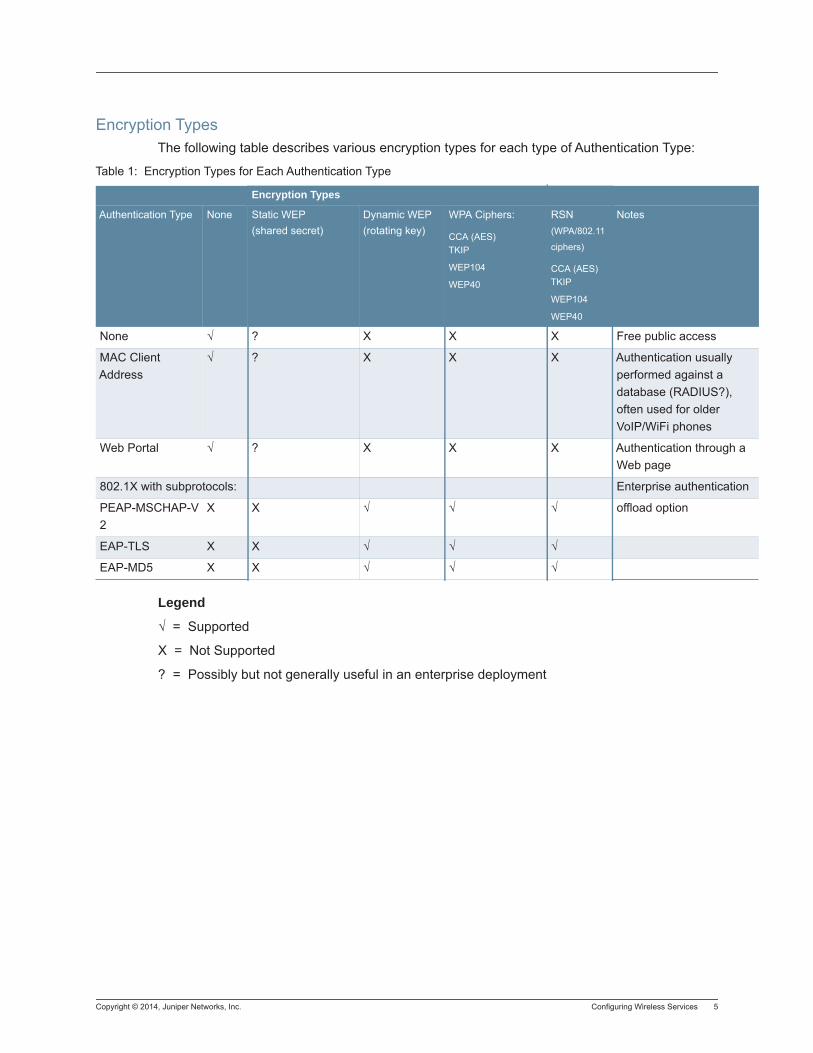
Copyright © 2014, Juniper Networks, Inc. Configuring Wireless Services 5
Encryption TypesThe following table describes various encryption types for each type of Authentication Type:
Legend
√ = Supported
X = Not Supported
? = Possibly but not generally useful in an enterprise deployment
Table 1: Encryption Types for Each Authentication Type
Encryption Types
Authentication Type None Static WEP(shared secret)
Dynamic WEP(rotating key)
WPA Ciphers:
CCA (AES)TKIP
WEP104
WEP40
RSN (WPA/802.11
ciphers)
CCA (AES)TKIP
WEP104
WEP40
Notes
None √ ? X X X Free public access
MAC Client Address
√ ? X X X Authentication usually performed against a database (RADIUS?), often used for older VoIP/WiFi phones
Web Portal √ ? X X X Authentication through a Web page
802.1X with subprotocols: Enterprise authentication
PEAP-MSCHAP-V2
X X √ √ √ offload option
EAP-TLS X X √ √ √
EAP-MD5 X X √ √ √

6 Configuring Wireless Services Copyright © 2014, Juniper Networks, Inc.
Copyright © 2014, Juniper Networks, Inc. Configuring a 802.1X Service Profile for Wireless Access 1
Configuring a 802.1X Service Profile for Wireless Access
NOTE: The 802.1X Service Profile wizard requires you to select one or more RADIUS server groups and does not allow you to complete the configuration without selecting one. Before you configure a 802.1X profile, a RADIUS server group must already be configured.
1. Access the 802.1X Service Profile wizard:
a. In the Organizer panel, click the plus sign next to a WLC to configure the service profile.
b. Click on the plus sign next to Wireless.
c. Select Wireless Services.
d. In the Tasks panel, select 802.1X Service Profile.
2. Read the description of the wizard on the first page, then click Next.
3. Type a service name in the Name field. Type a SSID name in the SSID field. Click Next.
4. Select the security standards supported by the SSID. Click Next.
5. The Wireless Encryption Cipher Suites dialog appears:
Select from the following:
− AES (CCAP) — Usually used with RSN (WPA2)
− TKIP — Usually used with WPA
− WEP-104 — Used with dynamic WEP
− WEP-40 — Used with dynamic WEP
6. Click Next.
7. Select one of the following from the Authentication Server(s) dialog.
8. Select an EAP Type:
− EAP-MD5 Offload
− PEAP Offload
− Local EAP-TLS
− External RADIUS Server
If you select PEAP, the EAP Sub-Protocol is MS-CHAPV2.
9. The Available RADUS Server Groups in the left column of the dialog can be added to the right column list of Current RADIUS Server Groups or they can be moved up, down or removed. Click Next.
10. To assign a default VLAN to the SSID, select a VLAN from the VLAN Name list.
11. VLAN and other authorization attributes can be assigned to users in the local database, on remote servers, or in the service profile of the SSID a user logs into. The VLAN selected here is used only if a VLAN attribute is not configured for a user on the RADIUS server or in the local database of a switch.
12. Click Next.
2 Configuring a 802.1X Service Profile for Wireless Access Copyright © 2014, Juniper Networks, Inc.
13. The Optional: Local User Database dialog is displayed. Select an existing user or click Create to configure a new user.
14. If you select an existing User, go to step 11. If you clicked Create, you next see the User Information dialog.
15. After selecting in the Local User Database, the optional Device Detection dialogue is displayed.
16. You can select from Disable to disable the feature. It is enabled by default. Or, Just Detect, which allows device detection but does not enforce any rules. Or, you can select Enforce, which enforces the device detection authorization rules. If you select Enforce, then you can configure the device detection timeout with a range of 1 to 60 seconds with a default value of 5 seconds. When you select enforce, the default ACL deviceacl is enabled. This ACL prevents access to the network until the device is recognized. Click Next.
17. The Radio Profile Selection dialog is displayed.
18. By default, the default radio profile is selected. Click Create new Radio Profile if you want to configure another radio profile. (link to subtask here) Select a Radio Profile and click Next.
19. You now see the 802.11n Attributes dialog. Select desired modes and settings and click Finish.
20. The service profile appears in the Service Profile table in the Content panel.
Copyright © 2014, Juniper Networks, Inc. Creating a 802.1X New User 1
Creating a 802.1X New User
1. Enter a user Name, Password, and select a Password Expiration Time [Hours] and User Group. Click Next.
2. You now see the Optional: Authorization Attributes dialog.
3. Enter or select a VLAN Name and use pop-up menus to set encryption-type and end-date.
4. Click Finish.

2 Creating a 802.1X New User Copyright © 2014, Juniper Networks, Inc.
Copyright © 2014, Juniper Networks, Inc. Creating a Web Portal Service Profile 1
Creating a Web Portal Service Profile
A Web Portal Service Profile creates a wireless service that allows users to authenticate using a Web browser. When the user attempts to connect to an SSID with this type of service profile, the user is redirected to a login page in a Web browser. After entering a username and password, the information is checked against a RADIUS server, or a local database, and access is granted or denied based on this information.
You can configure this type of profile for an encrypted or unencrypted SSID.
1. From the Organizer panel, select a WLC.
2. Under Wireless, select Wireless Services.
3. In the Task panel, under Create, click Web Portal Service Profile.
4. A brief description of the wizard is displayed.
5. Click Next.
6. Create a unique name to identify the profile.
7. Enter an SSID for the profile.
8. From the SSID Type list, select Encrypted (most secure) or Clear (least secure).
9. Click Next.
10. If you selected Encrypted, select the encryption type:
RSN (WPA2) — most secure
WPA — moderately secure
Static WEP — least secure
11. Click Next.
12. If you selected RSN or WPA, enter the preshared key or click Generate to create a new one. Click Next.
13. Select one or more of the following Wireless Encryption Cipher Suites:
AES (CCMP) — most secure
TKIP — moderately secure
WEP-104 — least secure
WEP-40 — least secure
Click Next.
14. From the VLAN Name list, select the VLAN for Web Portal Users. Click Next.
15. A Web Portal ACL (portalacl) is created by default. This prevents users from accessing the network before completing the authentication process. At this point, you can add additional IP-based rules if you require them.
16. Click Next.
2 Creating a Web Portal Service Profile Copyright © 2014, Juniper Networks, Inc.
17. Select a AAA Server from the list of Available Server Groups. Click Add to move it to the Current AAA Server Groups. If there is no group configured, click Create Server Group. Click Next to continue the configuration.
18. Select a radio profile from the Radio Profiles list, or you can create a new one.
19. Optionally, you can select radios as members of the Service Profile. Select radio profile members and move them from Available Members to Current members with the Move button and the reverse with the Reset to Default button.
20. Click Finish to complete the configuration.
Copyright © 2014, Juniper Networks, Inc. Creating an Avaya Voice Service Profile 1
Creating an Avaya Voice Service Profile
Creating an Avaya VoWIP Service Profile:
1. Select Configuration on the toolbar.
2. In the Organizer panel, expand the WLC.
3. Expand Wireless, then select Wireless Services.
4. In the Tasks panel, select Voice Service Profile.
5. Click Next.
6. Change the service profile name to Voice-Avaya, and use the name Voice-Avaya for the SSID. Select Avaya from the Vendor list.
7. Click Next.
8. Select Open Access and clear the MAC Access checkbox.
9. Click Next.
10. Select WPA and clear Static WEP.
11. Click Next.
12. Leave TKIP enabled and click Next.
13. Type a passphrase from 8 to 63 characters long in the Pre-shared Key field and click Generate.
14. Click Next.
15. Type or select the name of the VLAN you want to place voice users in. For this example, use Voice-VLAN2.
16. Click Next.
17. An ACL is automatically created for this type of Voice Profile. The first rule in the ACL provides high -priority treatment of SVP traffic by marking IP protocol 119 (SVP) packets with CoS 7. The second rule permits all other traffic in the VLAN.
18. Enter the Source and Destination MAC Addresses.
19. Click Next.
20. Select a Radio Profile from the Radio Profiles list. and click Finish. A wireless profile Voice-Avaya is created and is displayed in the content panel.

2 Creating an Avaya Voice Service Profile Copyright © 2014, Juniper Networks, Inc.
Copyright © 2014, Juniper Networks, Inc. Creating a Spectralink™ Voice Service Profile 1
Creating a Spectralink™ Voice Service Profile
Creating a Spectralink™ VoWIP Service Profile:
1. Select Configuration on the toolbar.
2. In the Organizer panel, expand the WLC.
3. Expand Wireless, then select Wireless Services.
4. In the Tasks panel, select Voice Service Profile.
5. Click Next.
6. Change the service profile name to Voice-SVP, and use the name Voice-SVP for the SSID. Select Spectralink from the Vendor list.
7. Click Next.
8. Select Open Access and clear MAC Access checkbox.
9. Click Next.
10. Select WPA and clear Static WEP.
11. Click Next.
12. Leave TKIP enabled and click Next.
13. Type a passphrase from 8 to 63 characters long in the Pre-shared Key field and click Generate.
14. Click Next.
15. Type or select the name of the VLAN you want to place voice users in. For this example, use VLAN2.
16. Click Next.
17. An ACL is automatically created for this type of Voice Profile. The first rule in the ACL provides high -priority treatment of SVP traffic by marking IP protocol 119 (SVP) packets with CoS 7. The second rule permits all other traffic in the VLAN.
18. Click Next.
19. Select a Radio Profile from the Radio Profiles list. and click Finish. A wireless profile Voice-SVP is created and is displayed in the content panel.

2 Creating a Spectralink™ Voice Service Profile Copyright © 2014, Juniper Networks, Inc.
Copyright © 2014, Juniper Networks, Inc. Creating an Vocera Voice Service Profile 1
Creating an Vocera Voice Service Profile
Creating an Vocera VoWIP Service Profile:
1. Select Configuration on the toolbar.
2. In the Organizer panel, expand the WLC.
3. Expand Wireless, then select Wireless Services.
4. In the Tasks panel, select Voice Service Profile.
5. Click Next.
6. Change the service profile name to Voice-Vocera, and use the name VoceraBadges for the SSID. Select Vocera from the Vendor list.
7. Click Next.
8. Leave MAC Access enabled.
9. Click Next.
10. Leave Static WEP enabled.
11. Click Next. Specify WEP keys.
. For each key (up to four), type the key value in the corresponding key field.
. By default, data in unicast and multicast packets are encrypted using WEP key 1. To use another key for either type of packet, select the key number in the WEP Unicast Key Index or WEP Multicast Key Index field.
12. Click Next.
13. Type or select the name of the VLAN you want to place voice users in. For this example, use Voice-VLAN.
14. Click Next.
15. Click Create to add MAC users to the local database WLC.
a. In the User MAC Address field, type the MAC address for the user device, using colons (:) as delimiters. You must specify all 6 bytes of the MAC address.
b. In the MAC User Group list, select the MAC user group for the user device, if the group is already configured.
c. In the VLAN Name field, select or type the name of the VLAN of the user device (1 to 16 alphanumeric characters, with no spaces or tabs). The WLC authorizes the user for that VLAN.
16. d. Click Next. In the attribute row you want to configure, click the Attribute Value column.
d. Click Finish.
17. Click Next. Select RadioProfileVoice in the Radio Profiles list.
18. Click Finish.

2 Creating an Vocera Voice Service Profile Copyright © 2014, Juniper Networks, Inc.
Copyright © 2014, Juniper Networks, Inc. Creating a W-Fi Multimedia (WMM) Voice Service Profile 1
Creating a W-Fi Multimedia (WMM) Voice Service Profile
Voice over Wireless IP (VoWIP) is a new technology, merging VoIP (Voice over IP) with 802.11 wireless LANs to create a wireless telephone system. Organizations that add VoWIP to the wireless LANs can deploy and manage voice and data over a single wireless backbone, reserving some portion of network bandwidth to support real-time voice communications. For a VoWIP service (sometimes also referred to simply as VoIP, or Voice over IP), you can configure either local or RADIUS server authentication, and add Access Lists (ACLs) to restrict user access.
The Voice Service Profile dialog tailors options based on the selected vendor. The dialog has the following vendor options:
SpectraLink
Avaya
Vocera
Other
The SpectraLink, Avaya, and Vocera options configure service for proprietary VoWIP solutions from these vendors. If you are configuring VoWIP for devices that use the Wi-Fi Multimedia (WMM) standard, or a proprietary solution other than one of the listed vendors, use the Other option.
Creating a WMM VoWIP Service Profile:
1. Select Configuration on the toolbar.
2. In the Organizer panel, expand the WLC.
3. Expand Wireless, then select Wireless Services.
4. In the Tasks panel, select Voice Service Profile.
5. Click Next.
6. Change the service profile name to Voice1, and use the name Voice1 for the SSID. Select Other from the Vendor list.
7. Click Next.
8. Select Open Access and clear MAC Access checkbox.
9. Click Next.
10. Select WPA and clear Static WEP.
11. Click Next.
12. Leave TKIP enabled and click Next.
13. Type a passphrase from 8 to 63 characters long in the Pre-shared Key field and click Generate.
14. Click Next.
15. Type or select the name of the VLAN you want to place voice users in. For this example, use VLAN2.

2 Creating a W-Fi Multimedia (WMM) Voice Service Profile Copyright © 2014, Juniper Networks, Inc.
16. Click Next.
17. Select Enable WMM.
18. Click Next.
19. Select a Radio Profile from the Radio Profiles list. and click Finish. A wireless profile Voice1 has been created and is shown in the content panel.
Copyright © 2014, Juniper Networks, Inc. Creating an Open Access Service Profile 1
Creating an Open Access Service Profile
1. From the Organizer panel, select a WLC.
2. Under Wireless, select Wireless Services.
3. In the Task panel, under Create, click Open Access Service Profile.
4. A brief description of the wizard is displayed.
5. Click Next.
6. Create a unique name to identify the profile.
7. Enter an SSID for the profile.
8. From the SSID Type list, select Encrypted (most secure) or Clear (least secure).
9. If you selected Encrypted, select the encryption type:
RSN (WPA2) — (Robust Security Network) most secure
WPA — (Wi-Fi Protected Access) moderately secure
Static WEP — (Wired Equivalent Privacy) least secure
10. Click Next.
11. If you selected RSN or WPA, enter the preshared key or click Generate to create a new one. Click New.
12. Select one or more of the following Wireless Encryption Cipher Suites:
AES (CCMP) — (AES-Counter Mode CBC-MAC Protocol) most secure
TKIP — (Temporal Key Integrity Protocol) moderately secure
WEP-104 — least secure
WEP-40 — least secure
Click Next.
13. If you selected Static WEP, specify WEP keys.
For each key (up to four), type the key value in the corresponding key field.
. By default, data in unicast and multicast packets are encrypted using WEP key 1. To use another key for either type of packet, select the key number in the WEP Unicast Key Index or WEP Multicast Key Index field.
14. From the VLAN Name list, select the VLAN for Open Access Users. Click Next.
15. Select a radio profile from the Radio Profiles list, or you can create a new one.
16. Click Finish to complete the configuration.

2 Creating an Open Access Service Profile Copyright © 2014, Juniper Networks, Inc.
Copyright © 2014, Juniper Networks, Inc. Creating an Mesh Service Profile 1
Creating an Mesh Service Profile
WLAN mesh services allow a WLA to provide wireless services to clients without a wired interface on the WLA. Instead of a wired interface, there is a radio link to another WLA with a wired interface. WLAN mesh services can be used at sites when running Ethernet cable to a location is inconvenient, expensive or impossible. Note that power must be available at the location where the Mesh WLA is installed.
1. From the Organizer panel, select a WLC.
2. Under Wireless, select Wireless Services.
3. In the Task panel, under Create, click Mesh Service Profile.
4. Create a unique name to identify the profile.
5. Enter an SSID for the profile.
6. If desired, Select Bridging to allow a WLA to bridge wireless traffic destined for a wired network.
7. Select the type of access for this profile:
Authenticate WLAs by MAC Address (default)
Allow Access to any WLA with a valid pre-shared key.
8. If you select authentication using a MAC address, select a MAC Address User from the list or click Create to add a new user.
9. If you select authentication using a pre-shared key, enter a preshared key in raw hexadecimal format. Or, enter a passphrase into the Preshared Key field and click Generate to obtain the hexadecimal format. You should set this key in the boot configuration of a WLA.
10. Select a radio profile from the Radio Profiles list, or you can create a new one. You must have a unique radio profile for mesh services.
11. Click Finish to complete the configuration.

2 Creating an Mesh Service Profile Copyright © 2014, Juniper Networks, Inc.
Copyright © 2014, Juniper Networks, Inc. Creating a Custom Service Profile 1
Creating a Custom Service Profile
If none of the other service types is appropriate, you can use the Custom Service Profile wizard to configure a service. The screens and options displayed depend on access types and elections you make as you use a wizard. All pages and options occur in at least one of the other service profile wizards
1. From the Organizer panel, select a WLC.
2. Under Wireless, select Wireless Services.
3. In the Task panel, under Create, click Custom Service Profile.
4. Create a unique name to identify the profile.
5. Enter an SSID for the profile.
6. From the SSID Type list, select Encrypted (most secure) or Clear (least secure).
7. Select the type of access for this profile:
802.1X Access
MAC Access
Web Access
Open Access
8. Click Next.
9. Select one or more wireless security standards.Click Next.
10. If you have a preshared key authenticating clients, enter it into the Preshared Key field and click Encrypt to encrypt the key. Click Next.
11. Select one or more wireless encryption suites. Click Next.
12. Select a VLAN for Open Access users.
13. Select a radio profile and click Finish to complete the configuration.

2 Creating a Custom Service Profile Copyright © 2014, Juniper Networks, Inc.
Copyright © 2014, Juniper Networks, Inc. Understanding Interworking Services 1
Understanding Interworking Services
Interworking Services allow users to configure hotspot profiles that are intended to help offload network traffic from cellular carriers to a Wi-Fi network to reduce traffic on expensive 3G/4G networks. Current solutions for hot spots require client devices to manually identify and select the local network as well authenticate to it. However, this service may offer only varying levels of security, bandwidth capability, and quality. The Juniper wireless LAN (WLAN) solution supports Hot Spot requirements and can seamlessly onboard Wi-Fi client devices at Hot Spot deployments that enables both mobile operators and Multiple System Operators (MSOs) to also offload mobile data traffic onto Wi-Fi Hot Spots. This feature is not supported in Local switching or WAN outage mode.
The following is a typical process for wireless devices when a hotspot is present:
1. A device with cellular and realms capability detects the Hot Spot capabilities in the access point beacon frame.
2. The device then queries the ANQP server on the controller for Third Generation Partnership Project (3GPP) cellular network information and roaming consortium organization identifiers (OIs).
3. The device matches the information and OIs received against a list of credentials and preferred networks.
4. The device automatically associates with the Hot Spot access point.
5. Authentication is performed using 802.1X to home authentication, authorization, and accounting (AAA) server using Extensible Authentication Protocol-Subscriber Identity Module (EAP-SIM), EAP-Authentication and Key Agreement (EAP-AKA), EAP-Transport Layer Security (EAP-TLS), or EAP-Tunneled Transport Layer Security (EAP-TTLS).

2 Understanding Interworking Services Copyright © 2014, Juniper Networks, Inc.

Copyright © 2014, Juniper Networks, Inc. Configuring an Interworking Service Profile for Wireless Access 1
Configuring an Interworking Service Profile for Wireless Access
1. Access the Interworking Service Profile wizard:
a. In the Organizer panel, click the plus sign next to a WLC to configure the service profile.
b. Click on the plus sign next to Wireless.
c. Select Interworking Services.
d. In the Tasks panel, select Interworking Profile.
2. Type a profile name in the Name field and click Next. This can be up to 255 characters.
3. Enter the desired HESSID. The Homogenous Extended Service Set Identifier (HESSID) that should be identical to one of the BSSIDs in HESS and is used to set the HESSID in the Interworking ID.
4. Use the Access Network Type options to specify whether the hotspot is public and allows Internet access and click Next.
5. Specify IP Address Type and Network Authentication Types using the drop-down menus provided. If needed, provide the Network Authentication Redirect URL as well.
6. Specify the Domain Name of the Hotspot provider and click Next.
7. To add Roaming Consortiums, click Create and follow the steps indicated. The Roaming Consortium IE contains information identifying the roaming consortium and or the subscription service provider (SSP) whose security credentials can be used to authenticate with the access point transmitting this element. Click Next when finished.
8. To add Network Access Identifier Realms, click Create and follow the steps indicated. Click Next to proceed.
9. Enter any Operator Names needed and click Next.
10. Check Enable Hotspot to enable the feature and click Next.
11. Click Create to configure 3rd Generation Partner Project (3GPP) codes. A public land mobile network (PLMN) is identified by the Mobile Country Code (MCC) and Mobile Network Code (MNC). This option configures a list of cellular networks that assist a non-access point with access to a 3GPP Cellular Network. Click Next when finished.
12. Click Finish to complete the profile creation.

2 Configuring an Interworking Service Profile for Wireless Access Copyright © 2014, Juniper Networks, Inc.
Copyright © 2014, Juniper Networks, Inc. Understanding Radio Profiles 1
Understanding Radio Profiles
A radio profile is a set of attributes that you can apply to multiple radios. A default radio profile named default is provided and cannot be deleted. Rather than configuring each radio individually, you can create a new radio profile and apply it to multiple radios that you select. You can also create a radio profile as part of a domain policy and apply the policy to WLAs on different WLCs.
The default radio profile is associated with the WLAs of a WLC, unless you created a new radio profile while configuring the coverage area and configured the WLCs with the information in the floor plan. If you create a new radio profile while configuring a coverage area for a floor, RingMaster automatically copies the new profile to the domain policy of the Mobility Domain selected for the coverage area. Later, when you configure WLCs in the Mobility Domain using the information in the floor plan, RingMaster also copies the radio profile to the Radio Profiles policy of each of the switches.

2 Understanding Radio Profiles Copyright © 2014, Juniper Networks, Inc.
Copyright © 2014, Juniper Networks, Inc. Creating Radio Profiles 1
Creating Radio Profiles
To create a Radio Profile, use the following steps:
1. In the Organizer panel, select a WLC.
2. Under Wireless, select Radio Profiles.
3. In the Tasks panel, under Create, click Create Radio Profile.
4. Enter a unique radio profile name in the Name field.
5. Click Next.
6. Select a radio or radios from the Available Members, and click Move to add it to the Current Members.
7. Click Next to continue configuring additional options or click Finish to save the Profile.
8. Click Next.
9. Select a Service Profile to apply to the Radio Profile and click add to move it to the Current Service Profiles.
10. Click Finish to save the configuration.
Configuring Advanced Radio SettingsAfter configuring a radio profile, select the radio profile, and click Properties to display a series of tabs that contain all of the configurable parameters for the radio profile. You can configure the following settings:
Radio Profile
Name — Radio profile name
Countermeasures Mode:
− None — Radios do not use countermeasures. This is the default.
− Rogue and Suspect — Sends probe any requests (probe requests with a null SSID name), to solicit probe responses from other access points. Radios also passively scan by listening for beacons and probe responses. When active scan is disabled, radios perform passive scanning only.
− Rogue — A rogue is a device that is in the Juniper network but does not belong there. An interfering device is not part of the Juniper network but also is not a rogue. MSS classifies a device as an interfering device if no client connected to the device has been detected communicating with any network entity listed in the forwarding database (FDB) of any WLC in the Mobility Domain. Although the interfering device is not connected to your network, the device might be causing RF interference with WLA radios. Radios use countermeasures against devices classified by MSS as rogues, but do not use countermeasures against devices classified by MSS as interfering devices.
Enable RFID — Enables support for RFID tags.
2 Creating Radio Profiles Copyright © 2014, Juniper Networks, Inc.
Enable U-APSD — Enables Unscheduled Automatic Powersave Delivery (U-APSD) on WLA radios managed by the radio profile. U-APSD enables WMM clients that use powersave mode to more efficiently request buffered unicast packets from WLA radios.
Restrict DFS Channels
Client Tx Power Constraint
RF Scanning
Mode
Channel Scope
Send CTS-to-Self
Enable/Disable Spectral Scan — enables Spectrum Analysis on the profile.
802.11 Attributes
Beacon Interval — Interval that the MP advertises the SSIDs. You can specify from 25 to 8191 milliseconds (ms). The default is 100 ms.
DTIM Period — (Delivery Traffic Information Message) Number of beacons (1 to 31) the WLA transmits before transmitting the multicast and broadcast frames stored in its buffers. The default is 1.
Fragment Threshold (bytes) — Frame length (256 to 2346 bytes) at which the long-retry-count is applicable instead of the short-retry-count. The default is 2,346 bytes.
Max Tx MDSU Lifetime (ms) — (MAC Data Service Unit) Maximum amount of time, from 500 ms to 250,000 ms (250 seconds), the MP can hold an outbound frame in buffer storage. The default value is 2,000 ms (2 seconds).
Max Rx MDSU Lifetime (ms) — Maximum amount of time, from 500 ms to 250,000 ms (250 seconds), the MP can hold an inbound frame in buffer storage. The default is 2000 ms (2 seconds).
RTS Threshold (bytes) — Minimum length (256 to 3000 bytes) a frame can be for the MP to use the Request-To-Send/Clear-To-Send (RTS/CTS) method to send the frame. Frames smaller than the RTS threshold are not sent using the RTS/CTS method. The default is 2346 bytes.
Enable Long Preambles — Enables advertisement of long preambles for 802.11b/g radios. This option is enabled by default. This option applies only to 802.11b/g radios.
Enable Rate Enforcement — When data rate enforcement is enabled, clients transmitting at the disabled rates are not allowed to associate with the WLA. Data rate enforcement is disabled by default.
802.11n Attributes
Channel Width
Copyright © 2014, Juniper Networks, Inc. Creating Radio Profiles 3
Auto Tune
Tune Channel — Automatically configures and tunes the channel. This feature is enabled by default.
Tune Transmit Power — Automatically configures and tunes the power. This feature is disabled by default.
Tx Power Tuning Interval (seconds) — Interval at which RF Auto-Tuning decides whether to change the power level on radios. You can specify from 1 to 65535 seconds. The default is 300 seconds.
Power Ramp Interval (seconds) — Interval at which power is increased or decreased, in 1 dBm increments, on radios until the optimum power level calculated by RF Auto-Tuning is reached. After each power ramp interval, the radio increases or decreases the power by another 1 dB until the radio reaches the power level selected by RF Auto-Tuning.
Power Policy—This drop-down allows the user to select which method of tuning will be used:
Maximum Coverage—Sets all radios to maximum transmit power based on the regulatory domain restrictions and access point model limitations. This is the default selection. When selected, none of the other options listed below the Power Policy field need to be modified.
Cell Parity—Set the same power on all radios, based on the radio capability and regulation. You can configure per-band power levels and the system accommodates these levels as allowed by regulatory constraints. For an equally spaced access point deployment, this power policy is better suited as it will not compute transmit power at run time. However, for very dense deployments, this policy may cause co-channel interference. When selected, users may specify the Cell Parity Power for both 2 GHz and 5 GHz bands.
Maximum Channel Capacity—This power policy automatically determines the best power levels for channel capacity, and avoids contention from other access points using the same channel. The administrator can change the parameters such as interval, minimum, and maximum power levels for the range, and the rate and degree to which power levels differ between access points in the vicinity. When selected, users can specify the minimum and maximum power ranges as well as the power density to be used.
Service Profile Selection
The Profile Selection tab lists the service profiles mapped to a radio profile. Radios managed by a radio profile provide wireless service for service profile SSIDs. To map a radio profile to a service profile, select a service profile from the Available Service Profiles list. Click Add to move the profile name to the Current Service Profiles list. To remove mapping between a radio profile and a service profile, select a service profile from the Current Service Profiles list. Click Remove to move the profile name to the Available Service Profiles list.
Informational Note: RF Auto-Tuning of channels on 802.11a radios uses only the bottom four channels in the band (36, 40, 44, and 48.) To use a higher channel number, you must disable RF Auto-Tuning of channels on the radio profile for the radio, and statically configure the channel. However, you can only configure channels legally allowed by the country code. The network plan configuration task Disable Auto-tune stamps current values into the permanent WLC configuration.
4 Creating Radio Profiles Copyright © 2014, Juniper Networks, Inc.
Available Service Profiles
Current Service Profiles
Radio Selection
The Radio Selection tab lists the radios managed by the radio profile. A radio can be managed by only one radio profile. To add a radio to the radio profile, select the radio in the Available Members list. Click Add to move the radio to the Current Members list. To remove a radio from the radio profile, select the radio from the Current Members list. Click Reset to Default to return the radio to the default radio profile.
Available Members
Current Members
Voice Configuration
QoS Mode — Classification and marking of high priority traffic on the WLC and WLA
− WMM — Classifies, marks, and forwards traffic for Wi-Fi Multimedia (WMM) devices based on 802.1p and DSCP values.
− SVP — Optimizes forwarding of SpectraLink Voice Priority (SVP) traffic by setting the random wait time a WLA radio waits before transmitting the traffic to 0 microseconds
WMM CAC Configuration
− Background 0 ACM Mode (Adaptive Coding and Modulation protocol)
− Background 0 ACM Limit (%)
− Background 0 ACM Policing
− Best-effort 1 ACM Mode
− Best-effort 1 ACM Limit (%)
− Best-effort 1 ACM Policing
− Video 2 ACM Mode
− Video 2 ACM Limit (%)
− Video 2 ACM Policing
− Voice 3 Mode
− Voice 3 ACM Limit (%)
− Voice ACM Policing
Bandwidth ManagementEnable Weighted Queuing
Snoop MapAvailable Snoop Filters
Current Snoop Filters
Copyright © 2014, Juniper Networks, Inc. Adaptive Channel Planner (Auto-Tune Enhancements) 5
Adaptive Channel Planner (Auto-Tune Enhancements)
OverviewA successful wireless LAN depends on efficient channel assignment by the WLAs. Channel assignment defines strategy of channel allocation that targets minimizing interference. Wireless interference, which causes low throughput due to collisions on the network, severely limits network capacity and can be minimized by using non-overlapping channels for neighboring WLAs.
The Adaptive Channel Planner improves radio channel assignment in the following situations:
New deployment - no existing channel configuration using either RingMaster or manually configuring the channels on the WLCs.
Existing configuration - improvement desired for any reason.
Moving or adding WLAs
Interference sources with channel-specific effects.
ACP provides better wireless connectivity to clients by dynamically assigning operating channels on WLAs. The benefits include:
Optimizing the use of available spectrum across the entire wireless network.
Reducing interference by avoiding medium access contention
Maximizing channel reuse
Avoiding performance degradation generated by spectrum overlap.
Restoring wireless connectivity in the presence of severe interference.
Minimize the impact of channel changes for wireless services.
Avoiding channel changing that makes the network plan less optimal than the previous plan.
Minimizing the impact of non-802.11 interference on the overall quality of service experience.
Functionality
Adaptive Channel Planner (ACP) dynamically assigns the WLA operating channel so that the wireless network can efficiently adapt to the RF environment conditions. Dynamic assignment can be changed when significant changes are measured in the interference level or in the network topology. Eventually, Wi-Fi bandwidth is maximized and maintains the efficiency of communication over the wireless network.
ACP is enabled by default, but you can disable it. It is also overwritten if a static channel set is configured. If ACP is not configured, channels on the WLAs are static and require manual intervention to change the channels.
Here's how it works:
Measure - MSS monitors the RF environment and collects interference information.
Calculate - MSS uses the measured data to calculate the best channel to assign on the WLA. This is a background function that does not impact other functions on the WLA.
6 Adaptive Channel Planner (Auto-Tune Enhancements) Copyright © 2014, Juniper Networks, Inc.
Deploy - MSS changes the operational channels when it is determined to have minimal impact on connected clients.
You can configure ACP to run at periodic intervals in order to calculate the next auto channel based on a measured interference level or when network changes are detected. MSS continuously searches for better channel assignment configurations, and separately monitors and controls 802.11a and 802.11b/g networks preventing unnecessary changes to one network if the other network is impacted.
You can select from channel sets and the default channel list includes only non-overlapping channels that meet regulatory requirements. This means that different channel sets are available based on the county code used in the configuration. Because of limited availability, channels are reused. The same channel is assigned to two WLAs, located far enough apart, if the overlapping channel interference signal detected by each WLA is less than a defined threshold. However, if radar is detected on the network, the channel is not available in the channel list for 30 minutes.
To improve the scaling characteristics of ACP, a new concept called "Interference Domain" is introduced. An InDo is defined as a set of radios in a MoDo that can interfere with each other. It only exists for the duration of an ACP cycle.
If a cluster configuration is enabled on the MoDo, ACP is applicable across the entire MoDo. Otherwise, the settings are restricted to the local configuration.
To configure Adaptive Channel Planner, select a radio profile and click Properties.
1. Click on the Adaptive Channel Planner tab.
2. To add specific channels on the 802.11b/g radio, select the tab and add channels by moving them from Available Channels to Current Channels.
3. To add specific channels on the 802.11a radio, select the tab and add channels by moving them from Available Channels to Current Channels.
Copyright © 2014, Juniper Networks, Inc. Setting Up Bandwidth Management 1
Setting Up Bandwidth Management
Select one or more options to manage bandwidth. You can enformce per SSID bandwidth limits, control how a radio bandwidth is shared across SSIDs, and configure QoS profiles to limit bandwidth and prioritize traffic individual users or SSIDs.
1. From the Organizer panel, select a WLC and then Wireless Services.
2. In the Tasks panel, under Setup, click Bandwidth Management.
3. All Bandwidth Management Options are selected by default. To disable an option, clear the corresponding checkbox.
4. Click Finish if you have disabled an option. To continue the configuration, click Next.
5. To configure limits for an SSID, select a Service Profile from the list.
6. Click Next.
7. To configure SSID Access Time for a radio profile, select the name from the Radio Profile Name list. To enable weighted queuing, select Enable Weighted Queuing.
8. Click Next.
9. Manage any configured QoS profiles, or create one.
10. Click Finish.

2 Setting Up Bandwidth Management Copyright © 2014, Juniper Networks, Inc.
Copyright © 2014, Juniper Networks, Inc. Creating a VLAN Profile 1
Creating a VLAN Profile
To create a VLAN Profile for Local Switching, use the following steps:
1. From the Organizer panel, select a WLC.
2. Under Wireless, select Local Switching.
3. In the Tasks panel, click Create VLAN Profile.
4. In the Name field, enter a unique name to identify the profile.
5. Click Next.
6. Select a VLAN from the Network Plan VLANs, and click Add to move it the the Current VLANs list.
7. If you do not have any VLANs configure, click Add VLAN to create a new one.
8. Click Next.
9. From the Available WLAs list, select WLAs to apply the profile. Click Move to add it to the Current WLAs list.
10. Click Finish to complete the configuration.

2 Creating a VLAN Profile Copyright © 2014, Juniper Networks, Inc.
Copyright © 2014, Juniper Networks, Inc. Setting Up L2 Restrictions for Local Switching 1
Setting Up L2 Restrictions for Local Switching
To set up L2 Restrictions for Local Switching, use the following steps:
1. From the Organizer panel, select a WLC.
2. Under Wireless, select Local Switching.
3. In the Tasks panel, under Setup, select L2 Restrictions.
4. From the VLANs list, select an available VLAN.
5. Click Next.
6. To enable L2 Traffic Restrictions on the VLAN, select Enable.
7. If there are no restrictions configured, click Create.
8. Enter a MAC address to use for the configuration, and click Finish.
9. Select the MAC address from the list, and click Finish.

2 Setting Up L2 Restrictions for Local Switching Copyright © 2014, Juniper Networks, Inc.
Copyright © 2014, Juniper Networks, Inc. Creating WLAs using RingMaster 1
Creating WLAs using RingMaster
To add WLAs, use the following steps:
1. In the Organizer panel, select a WLC.
2. Under Wireless, click Access Points.
3. In the Tasks panel, under Create, click WLA.
4. Create a unique identity for the WLA. Enter a number, unique name, connection type, and description. Click Next.
5. Enter the WLA serial number in the Serial Number field. If you plan to configure security between the WLA and a WLC, enter the unique fingerprint for the WLA.
6. Click Next.
7. Select the WLA type from the WLA Model list. The Radio 1 Type and Radio 2 Type are automatically populated when you select the WLA Model.
8. Click Next.
9. Configure the Radio 1 parameters:
Number
Radio Mode
Radio Profile
Channel Number
Transmit Power [dBm]
Antenna Location
Antenna Type
10. Click Next.
11. Configure the Radio 2 parameters:
Number
Radio Mode
Radio Profile
Channel Number
Transmit Power [dBm]
Antenna Location
Antenna Type
12. Click Finish to save the configuration.

2 Creating WLAs using RingMaster Copyright © 2014, Juniper Networks, Inc.
Copyright © 2014, Juniper Networks, Inc. Managing Access Points Using RingMaster 1
Managing Access Points Using RingMaster
If you currently have access points in a RingMaster plan, use these steps to change the configuration”
1. From the Organizer panel, select a WLC.
2. Under Wireless, select Access Points.
3. In the Configuration panel, you can change the following settings:
Security Mode - select from Optional, None, or Required.
Enable Auto WLA
Load Balancing - enabled by default.
4. For existing WLAs in RingMaster, you can highlight them in the list and click Properties.
5. You can change or add the following properties to a WLA:
Access Point
− WLA Number
− Name
− WLA Mode
− Description
− Radio Type
− Serial Number
− Connection
− Fingerprint
− Location
− Contact
− WLA Communication Timeout
− Enable Data Security
− Bias
− Enable Firmware Update
− Force Image Download
− Enable Blink
− LED Mode
− Local Switching
Remote WLA
− Enable Remote WLA
− Outage Duration [hours]
− Connection Evaluation Period [seconds]
− High Latency Mode
LLDP
2 Managing Access Points Using RingMaster Copyright © 2014, Juniper Networks, Inc.
− LLDP Mode
− LLDP-MED Mode
− Power via MDI
− Inventory
802.11ng Radio
− Number
− Radio Mode
− Radio Profile
− Channel Number
− Transmit Power [dBm]
− Antenna Location
− Antenna Type
− Antenna Span [degrees]
− Antenna Direction [degrees]
− Cable Loss [dBm]
− Auto Tune
> Max Transmit Power
− Load Balancing
> Enable Load Balancing
> Load Balance Group
> Rebalance Clients
802.11na Radio
− Number
− Radio Mode
− Radio Profile
− Channel Number
− Transmit Power [dBm]
− Antenna Location
− Antenna Type
− Antenna Span [degrees]
− Antenna Direction [degrees]
− Cable Loss [dBm]
− Auto Tune
> Max Transmit Power
− Load Balancing
> Enable Load Balancing
> Load Balance Group
> Rebalance Clients
Copyright © 2014, Juniper Networks, Inc. Managing Access Points Using RingMaster 3
WLA Redundancy
− Select or Create a Connection
6. Click OK to save the changes.
Deleting an Existing WLATo delete a WLA from the current configuration, select the WLA from the list and click Delete. The WLA is removed from the configuration.

4 Managing Access Points Using RingMaster Copyright © 2014, Juniper Networks, Inc.
Copyright © 2014, Juniper Networks, Inc. Creating a WLA Number 1
Creating a WLA Number
To set up WLA Number, use the following steps:
1. In the Organizer panel, select a WLC.
2. Under Wireless, click Access Points.
3. In the Tasks panel, under Setup, click WLA Number.
4. Create a new and unique WLA number.
5. Click OK to change the WLA Number.

2 Creating a WLA Number Copyright © 2014, Juniper Networks, Inc.
Copyright © 2014, Juniper Networks, Inc. Setting Up WLA Model 1
Setting Up WLA Model
To set up WLA model, use the following steps:
1. In the Organizer panel, select a WLC.
2. Under Wireless, click Access Points.
3. In the Tasks panel, under Setup, click WLA Model.
4. From the WLA list, select a WLA model.
5. Click OK to change the WLA Model.

2 Setting Up WLA Model Copyright © 2014, Juniper Networks, Inc.
Copyright © 2014, Juniper Networks, Inc. Setting Up WLA Boot Configuration 1
Setting Up WLA Boot Configuration
To set up WLA Boot Configuration, use the following steps:
1. In the Organizer panel, select a WLC.
2. Under Wireless, click Access Points.
3. In the Tasks panel, under Setup, click WLA Boot Configuration.
4. From the WLA list, select a WLA to apply the configuration.
5. Click Change Boot Parameters.
6. To clear the boot configuration, select Clear Configuration.
7. Under Mesh, to enable the feature, select Mesh Enabled. You can also generate a Mesh PSK and add the SSID.
8. Under IP, if the WLA boots from a static IP address, select Static IP Enabled. Enter the Gateway, Static IP Address, and Netmask.
9. Under Switch, if the WLA boots from a specific WLC, select Static WLC Enabled. Enter the Static IP WLC Address, Static WLC Name, and Static IP DNS Address.
10. Under VLAN, if the WLA is assigned to a VLAN, select Static VLAN Enabled, and the Static VLAN Tag.
11. Click OK to add the configuration.
12. Click Next to deploy the changes.
13. Click Finish to close the wizard.

2 Setting Up WLA Boot Configuration Copyright © 2014, Juniper Networks, Inc.
Copyright © 2014, Juniper Networks, Inc. Setting Up Load Balancing 1
Setting Up Load Balancing
RF load balancing is the ability to reduce network congestion over an area by distributing client sessions across the WLAs with overlapping coverage in the area. When the total demand of nearby wireless clients exceeds the capacity of a single WLA, there is no interruption of wireless services on the network.
For example, in an auditorium or lecture hall, there may be a substantial number of clients in a relatively small amount of space. While a single WLA may be sufficient for providing an RF signal to the entire area, more WLAs are required to deliver enough aggregate bandwidth for all of the clients. When additional WLAs are installed in the room, RF load balancing allows the client sessions to be spread evenly across the WLAs, increasing the available aggregate bandwidth by increasing the number of WLAs.
RF load balancing is enabled by default. In addition, RF load balancing is done on a per-radio basis, rather than a per-WLA basis. For radios managed by a given radio profile, RingMaster automatically assesses radios with overlapping coverage in an area and balances the client load across them.
RingMaster balances the client load by adjusting how WLAs are perceived by clients. As the capacity of a WLA handling new clients is relative to other WLAs in the area, RingMaster makes the WLA more difficult for potential new clients to detect, which causes a client to associate with a WLA with more capacity. A WLA becomes more difficult to detect and clients then associate with a WLA with higher capacity for client sessions. By default RingMaster only prevents clients from associating with a WLA if there are other WLAs with available capacity. Clients are not prevented from associating with a WLA if it is the only one available.
You can optionally place WLA radios into load balancing groups. When two or more WLA radios are placed in the same load balancing group, RingMaster assumes that they have exactly the same coverage area, and attempts to distribute the client load across them equally. The WLA radios do not have to be on the same WLC. A balanced set of WLA radios can span multiple WLC switches in a Mobility Domain.
To set up Load Balancing, use the following steps:
1. In the Organizer panel, select a WLC.
2. Under Wireless, click Access Points.
3. In the Tasks panel, under Setup, click Load Balancing.
4. To enable Load Balancing between WLAs, select Load Balancing.
5. Configure the Load Balancing Strictness, by selecting from the following options:
− Low - No clients are denied service.
− Medium - Clients attempting to connect to overloaded WLAs are redirected to other WLAs causing a few seconds delay before connecting to the network.
− High - Clients may be delayed up to a minute before connecting to the network.
− Max -
6. Select the preferred bandwidth, and click Next.

2 Setting Up Load Balancing Copyright © 2014, Juniper Networks, Inc.
7. Configure Load Balancing for each radio. You can enable the Rebalance Clients option, and click Next.
8. Select the Service Profiles to apply Load Balancing, and also select which Service Profiles are exempt from this feature.
9. Click Finish to add the configuration.
Copyright © 2014, Juniper Networks, Inc. Setting Up WLA Redundancy 1
Setting Up WLA Redundancy
To setup WLA Redundancy, use the following steps:
1. In the Organizer panel, select a WLC.
2. Under Wireless, click Access Points.
3. In the Tasks panel, under Setup, click WLA Redundancy.
4. To add a WLA, click Create.
5. If you have a directly connected WLA, configure the WLA Connection settings:
a. WLC - select a WLC from the list.
b. Port
c. Bias
d. PoE - if you want the WLA to receive power from the WLC, select this option.
6. Click Finish to add the connection.
7. If you have a WLA previously configured for redundancy, you can edit the connection properties by selecting the WLA, and then clicking Properties.

2 Setting Up WLA Redundancy Copyright © 2014, Juniper Networks, Inc.
Copyright © 2014, Juniper Networks, Inc. Setting Up WLA Radio Type 1
Setting Up WLA Radio Type
To set up WLA Radio Type, use the following steps:
1. In the Organizer panel, select a WLC.
2. Under Wireless, click Access Points.
3. In the Tasks panel, under Setup, click WLA Radio Type.
4. Select a Radio Type from the list.
5. Click OK to change the WLA Radio Type.

2 Setting Up WLA Radio Type Copyright © 2014, Juniper Networks, Inc.
Copyright © 2014, Juniper Networks, Inc. Configuring Remote WLA using RingMaster 1
Configuring Remote WLA using RingMaster
In some network deployments, it is common to have a central network site with WLCs and remote sites with WLAs. The central and remote sites are connected by a WAN link. If the WAN link becomes unavailable, then the remote sites with WLAs remain active and continue to provide connectivity to wireless clients.
Once an outage has occurred, a periodic timer sends discovery messages to the primary access manager (PAM) to detect when the WLC is available on the network again. This timer, called an evaluation timer, is configurable and can be used as a hold-down timer to confirm detection of the WAN outage and as a mechanism to detect when the connection is restored.
A remote office can be any one of the following types of environments:
Small retail store using the corporate database for inventory control and the Internet for financial transactions.
Remote investment office with local servers, IP/PBX, and access to the corporate network for financial information.
Remote sales office with access to the corporate network only.
A temporary office at an event or exhibition with local printers and access to the corporate database across the WAN.
A hot spot deployed at a retail facility, such as a coffee shop, providing Internet access only.
A healthcare clinic that requires access to centralized hospital data in addition to local networking services such as printers and servers.
Once you have installed RingMaster Version 7.5 or later, you can configure WLAs for Remote WLA using the following steps:
1. In the Organizer panel, select a WLC from the list and then Access Points.
2. On the Navigation bar, click Configuration.
3. Select an Access Point from the list of Access Points, and click Properties.
4. Click the Remote WLA tab to display the options for configuring a Remote WLA.
5. Select Enable Remote WLA.
6. In the Outage Duration [hours], configure the length of time for the WLA to stay in outage mode.The default setting is 0 (stay in outage mode indefinitely) and the range is from 0 to 120 hours (5 days). This period indicates the maximum length of time that a WLA remains in outage mode.
7. In the Connection Evaluation Period [seconds], configure the length of time for the keepalive interval of the pings sent to detect when the WAN link is active on the network. The default value is 300 seconds with a range of 5 to 86400 seconds.
8. Click OK to save the changes in RingMaster.
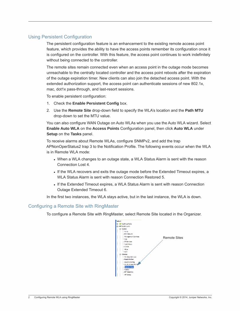
2 Configuring Remote WLA using RingMaster Copyright © 2014, Juniper Networks, Inc.
Using Persistent ConfigurationThe persistent configuration feature is an enhancement to the existing remote access point feature, which provides the ability to have the access points remember its configuration once it is configured on the controller. With this feature, the access point continues to work indefinitely without being connected to the controller.
The remote sites remain connected even when an access point in the outage mode becomes unreachable to the centrally located controller and the access point reboots after the expiration of the outage expiration timer. New clients can also join the detached access point. With the extended authorization support, the access point can authenticate sessions of new 802.1x, mac, dot1x pass-through, and last-resort sessions.
To enable persistent configuration:
1. Check the Enable Persistent Config box.
2. Use the Remote Site drop-down field to specify the WLA’s location and the Path MTU drop-down to set the MTU value.
You can also configure WAN Outage on Auto WLAs when you use the Auto WLA wizard. Select Enable Auto WLA on the Access Points Configuration panel, then click Auto WLA under Setup on the Tasks panel.
To receive alarms about Remote WLAs, configure SNMPv2, and add the trap APNonOperStatus2 trap 3 to the Notification Profile. The following events occur when the WLA is in Remote WLA mode:
When a WLA changes to an outage state, a WLA Status Alarm is sent with the reason Connection Lost 4.
If the WLA recovers and exits the outage mode before the Extended Timeout expires, a WLA Status Alarm is sent with reason Connection Restored 5.
If the Extended Timeout expires, a WLA Status Alarm is sent with reason Connection Outage Extended Timeout 6.
In the first two instances, the WLA stays active, but in the last instance, the WLA is down.
Configuring a Remote Site with RingMasterTo configure a Remote Site with RingMaster, select Remote Site located in the Organizer.
Remote Sites
Copyright © 2014, Juniper Networks, Inc. Configuring Remote WLA using RingMaster 3
Once you select Remote Sites in the Organizer, click Create Remote Site to launch the configuration wizard. The wizard allows you to configure the following parameters:
Unique Name
Country Code
Enable Security
VLAN Profile
Path MTU
Enable Backup SSIDs Mode
Add WLAs
Enable Intrusion Detection Logging

4 Configuring Remote WLA using RingMaster Copyright © 2014, Juniper Networks, Inc.
Copyright © 2014, Juniper Networks, Inc. Converting Auto WLAs 1
Converting Auto WLAs
To an Auto WLA to a configured WLA, use the following steps:
1. In the Organizer panel, select a WLC.
2. Under Wireless, click Access Points.
3. In the Tasks panel, under Other, click Convert Auto WLA.
4. From the list of Auto WLAs, select one to convert to a configured WLA, and click Next.
5. Change the WLA Number to a unique number, and click Next.
6. The selected WLA is converted to a configured WLA.
7. Click Finish.

2 Converting Auto WLAs Copyright © 2014, Juniper Networks, Inc.
Copyright © 2014, Juniper Networks, Inc. Removing Auto WLAs 1
Removing Auto WLAs
To remove an Auto WLA, use the following steps:
1. In the Organizer panel, select a WLC.
2. Under Wireless, click Access Points.
3. In the Tasks panel, under Other, click Remove Auto WLA.
4. From the list of Auto WLAs, select one to remove, and click Next.
5. The selected WLA is removed from the network plan.
6. Click Finish.

2 Removing Auto WLAs Copyright © 2014, Juniper Networks, Inc.
Copyright © 2014, Juniper Networks, Inc. Configuring a Remote Site 1
Configuring a Remote Site
In some network deployments, it is common to have a central network site with WLCs and remote sites with WLAs. The central and remote sites are connected by a WAN link. If the WAN link becomes unavailable, then the remote sites with WLAs should remain active and continue to provide connectivity to wireless clients.
Once an outage has occurred, a periodic timer sends discovery messages to the primary access manager (PAM) to detect when the WLC is available on the network again. This timer, called an evaluation timer, is configurable and can be used as a hold-down timer to confirm detection of the WAN outage and as a mechanism to detect when the connection is restored.
For detailed information on this feature, refer to the MSS Configuration Guide.
To configure a WLA for a remote site, use the following steps:
1. In the Organizer panel, select a WLC.
2. Under Wireless, click Remote Sites.
3. In the Tasks panel, under Create, click Create Remote Site.
4. The Create Remote Site wizard is displayed.
5. Enter a name for the remote site.
6. Select a Country Code. WLAs can reside in different countries other than the network plan.
7. Select a VLAN Profile.
8. Configure the Path MTU, if desired.
9. Backup SSIDs Mode is enabled by default.
10. Click Next.
11. Select a WLA from the list and click Add.
12. Click Next.
13. Intrusion Detection Logging is enabled by default. You need to enter the IP address of the server that is logging the events, and the port. You can also select the Severity Filter level.
14. Click Finish to complete the configuration.

2 Configuring a Remote Site Copyright © 2014, Juniper Networks, Inc.
Copyright © 2014, Juniper Networks, Inc. Configuring Radio Properties 1
Configuring Radio Properties
To configure or modify radio properties, use the following steps:
1. In the Organizer panel, select a WLC.
2. Under Wireless, click Radios.
3. In the 2.4 GHz or 5 GHz section, you can select a radio and change the following properties:
− Radio Mode —select Enabled, Disabled, or Sentry
− Channel — select a channel from 1 to 11.
− Tx Power — select a transmit power from 5 to 18.
− Antenna — select the antenna type, either Internal or a specific model.
− Radio Profile — select from a list of configured Radio Profiles to apply to the radio.
4. To display all of the Radio Properties, highlight the radio in the list, and click Properties.
5. Additional properties are now displayed that can be configured.
− Additional Antenna options include Antenna Span, Antenna Direction, Antenna Tilt, and Cable Loss.
− Auto Tune — select the default setting or 1 to 20 for the maximum transmit power.
− Load Balancing — “see WLA Load Balancing”
6. Auto Channel is selected by default. To manually configure a channel, clear the checkbox, and then select a channel from the Channel Number list.
7. To add a Snoop Map to the radio, click the Snoop Map tab.
8. Snoop Filters are displayed in the Available Snoop Filters list. To add a Snoop Filter, select it from the list and click Add. The Snoop Filter is now displayed in the Current Snoop Filters list.
9. Click OK to save the configuration.

2 Configuring Radio Properties Copyright © 2014, Juniper Networks, Inc.
Copyright © 2014, Juniper Networks, Inc. Changing Radio Modes 1
Changing Radio Modes
To change the radio mode, use the following steps:
1. Select a radio from the list of available radios. You can select all radios by checking Select.
1. From the Radio Mode options, select Enabled to allow radio operations. To configure the radio in Sentry mode, select Sentry.
2. Click OK to complete the configuration.

2 Changing Radio Modes Copyright © 2014, Juniper Networks, Inc.
Copyright © 2014, Juniper Networks, Inc. Configuring RF Detection 1
Configuring RF Detection
To configure RF Detection, use the following steps:
1. In the Organizer panel, select a WLC.
2. Under Wireless, click RF Detection.
3. In the Configuration - RF section, you can select Enable WLA Signature, and add a WLA Signature to detect on the network.
4. If you enable Dynamic Blacklist, client MAC addresses are automatically prevented from joining the wireless network. You can specify a length of time from 0 to 300 seconds. The default value is 300 seconds.
5. Click Save to save the configuration.

2 Configuring RF Detection Copyright © 2014, Juniper Networks, Inc.
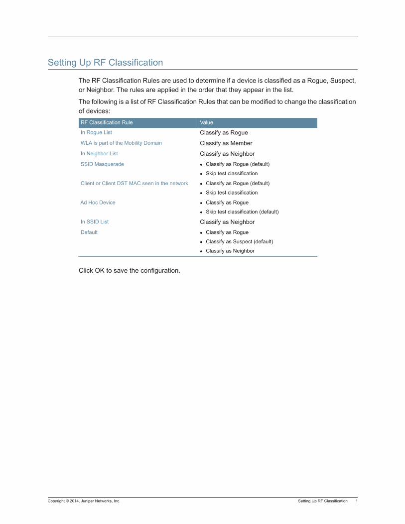
Copyright © 2014, Juniper Networks, Inc. Setting Up RF Classification 1
Setting Up RF Classification
The RF Classification Rules are used to determine if a device is classified as a Rogue, Suspect, or Neighbor. The rules are applied in the order that they appear in the list.
The following is a list of RF Classification Rules that can be modified to change the classification of devices:
Click OK to save the configuration.
RF Classification Rule Value
In Rogue List Classify as Rogue
WLA is part of the Mobility Domain Classify as Member
In Neighbor List Classify as Neighbor
SSID Masquerade Classify as Rogue (default)
Skip test classification
Client or Client DST MAC seen in the network Classify as Rogue (default)
Skip test classification
Ad Hoc Device Classify as Rogue
Skip test classification (default)
In SSID List Classify as Neighbor
Default Classify as Rogue
Classify as Suspect (default)
Classify as Neighbor

2 Setting Up RF Classification Copyright © 2014, Juniper Networks, Inc.
Copyright © 2014, Juniper Networks, Inc. Setting Up Countermeasures Mode 1
Setting Up Countermeasures Mode
You can configure on a per radio profile basis how the network responds to intrusive traffic on the network.
To configure this feature, use the following steps:
1. Select a WLC from the network plan.
2. Under Wireless, select RF Detection.
3. On the Configuration - RF Detection page, under Device Containment, select a Radio Profile from the list.
4. Select the type of Countermeasures Mode from the list. You can select from the following options:
− None
− Rogue and Suspect
− Rogue
5. If you select Properties, you can change the Radio Profile options. See “Configuring a Radio Profile”.

2 Setting Up Countermeasures Mode Copyright © 2014, Juniper Networks, Inc.
Copyright © 2014, Juniper Networks, Inc. Setting Up 802.11 Client Types 1
Setting Up 802.11 Client Types
You can configure on a per service profile basis the client types allowed on a specific service profile.
To configure this feature, use the following steps:
1. Select a WLC from the network plan.
2. Under Wireless, select RF Detection.
3. Under Setup, click 802.11 Client Types.
4. From the list of Service Profiles, select or clear the following client types from the profile:
− 802.11a
− 802.11b
− 802.11g
− [email protected] GHz
− 802.11n@5 GHz
5. Click OK to save the changes.

2 Setting Up 802.11 Client Types Copyright © 2014, Juniper Networks, Inc.
Copyright © 2014, Juniper Networks, Inc. Creating a Rogue List Entry 1
Creating a Rogue List Entry
To add an entry to the Rogue list, use the following steps:
1. In the Organizer panel, select a WLC.
2. Under Wireless, click RF Detection.
3. In the Task list, under Create, click Rogue List Entry.
4. Enter the MAC address of the Rogue Device.
5. Click OK.
6. The MAC address is now displayed in the Rogue List.
7. To delete the MAC address from the Rogue List, select the MAC address and click Delete.

2 Creating a Rogue List Entry Copyright © 2014, Juniper Networks, Inc.
Copyright © 2014, Juniper Networks, Inc. Creating a Neighbor List Entry 1
Creating a Neighbor List Entry
To add an entry to the Rogue list, use the following steps:
1. In the Organizer panel, select a WLC.
2. Under Wireless, click RF Detection.
3. In the Task list, under Create, click Neighbor List Entry.
4. Select MAC or Vendor IDs as the Device Identifier.
5. Click Next.
6. If you select MAC, enter the MAC address.
7. Click Finish to add the MAC address.
8. If you selected Vendor IDs, select the vendor from the Vendor list.
9. Then select the Vendor IDs from the list, and click Add to add the to the Selected Vendor ID list. You can also add a Vendor that is not listed, and add the OUI. to the list.
10. Click Finish.
11. The Neighbor Entry is now displayed in the Neighbor List.
12. To delete the MAC address from the Rogue List, select the MAC address and click Delete.

2 Creating a Neighbor List Entry Copyright © 2014, Juniper Networks, Inc.
Copyright © 2014, Juniper Networks, Inc. Creating a Known SSID List Entry 1
Creating a Known SSID List Entry
To add an entry to the Known SSID list, use the following steps:
1. In the Organizer panel, select a WLC.
2. Under Wireless, click RF Detection.
3. In the Task list, under Create, click Known SSID List Entry.
4. Enter the SSID name in the SSID field.
5. Click OK.
6. The SSID Entry is now displayed in the Known SSID List.
7. To delete the SSID from the Known SSID List, select the SSID and click Delete.

2 Creating a Known SSID List Entry Copyright © 2014, Juniper Networks, Inc.
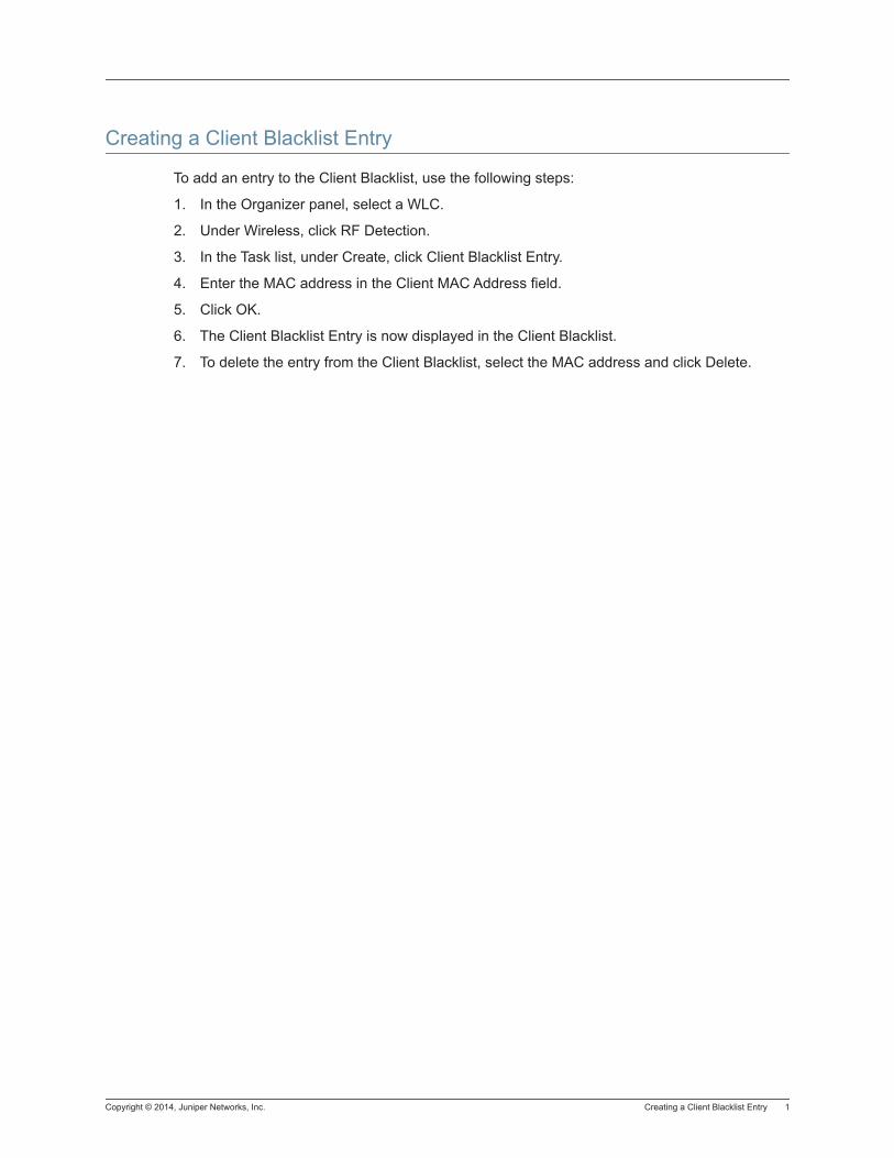
Copyright © 2014, Juniper Networks, Inc. Creating a Client Blacklist Entry 1
Creating a Client Blacklist Entry
To add an entry to the Client Blacklist, use the following steps:
1. In the Organizer panel, select a WLC.
2. Under Wireless, click RF Detection.
3. In the Task list, under Create, click Client Blacklist Entry.
4. Enter the MAC address in the Client MAC Address field.
5. Click OK.
6. The Client Blacklist Entry is now displayed in the Client Blacklist.
7. To delete the entry from the Client Blacklist, select the MAC address and click Delete.

2 Creating a Client Blacklist Entry Copyright © 2014, Juniper Networks, Inc.
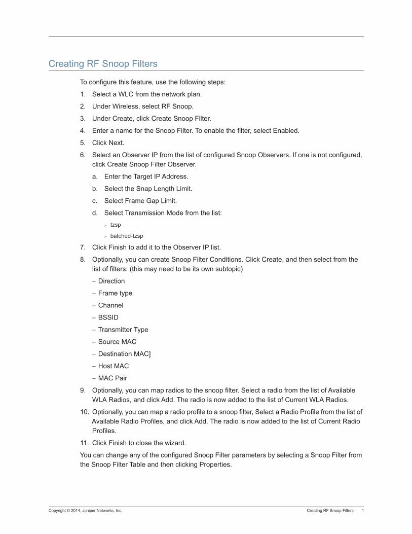
Copyright © 2014, Juniper Networks, Inc. Creating RF Snoop Filters 1
Creating RF Snoop Filters
To configure this feature, use the following steps:
1. Select a WLC from the network plan.
2. Under Wireless, select RF Snoop.
3. Under Create, click Create Snoop Filter.
4. Enter a name for the Snoop Filter. To enable the filter, select Enabled.
5. Click Next.
6. Select an Observer IP from the list of configured Snoop Observers. If one is not configured, click Create Snoop Filter Observer.
a. Enter the Target IP Address.
b. Select the Snap Length Limit.
c. Select Frame Gap Limit.
d. Select Transmission Mode from the list:
> tzsp
> batched-tzsp
7. Click Finish to add it to the Observer IP list.
8. Optionally, you can create Snoop Filter Conditions. Click Create, and then select from the list of filters: (this may need to be its own subtopic)
− Direction
− Frame type
− Channel
− BSSID
− Transmitter Type
− Source MAC
− Destination MAC]
− Host MAC
− MAC Pair
9. Optionally, you can map radios to the snoop filter. Select a radio from the list of Available WLA Radios, and click Add. The radio is now added to the list of Current WLA Radios.
10. Optionally, you can map a radio profile to a snoop filter, Select a Radio Profile from the list of Available Radio Profiles, and click Add. The radio is now added to the list of Current Radio Profiles.
11. Click Finish to close the wizard.
You can change any of the configured Snoop Filter parameters by selecting a Snoop Filter from the Snoop Filter Table and then clicking Properties.

2 Creating RF Snoop Filters Copyright © 2014, Juniper Networks, Inc.
You can change any of the Snoop Observers parameter by selecting an Observer from the Snoop Observers table, and clicking Properties.
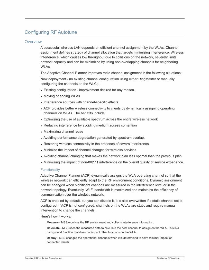
Copyright © 2014, Juniper Networks, Inc. Configuring RF Autotune 1
Configuring RF Autotune
OverviewA successful wireless LAN depends on efficient channel assignment by the WLAs. Channel assignment defines strategy of channel allocation that targets minimizing interference. Wireless interference, which causes low throughput due to collisions on the network, severely limits network capacity and can be minimized by using non-overlapping channels for neighboring WLAs.
The Adaptive Channel Planner improves radio channel assignment in the following situations:
New deployment - no existing channel configuration using either RingMaster or manually configuring the channels on the WLCs.
Existing configuration - improvement desired for any reason.
Moving or adding WLAs
Interference sources with channel-specific effects.
ACP provides better wireless connectivity to clients by dynamically assigning operating channels on WLAs. The benefits include:
Optimizing the use of available spectrum across the entire wireless network.
Reducing interference by avoiding medium access contention
Maximizing channel reuse
Avoiding performance degradation generated by spectrum overlap.
Restoring wireless connectivity in the presence of severe interference.
Minimize the impact of channel changes for wireless services.
Avoiding channel changing that makes the network plan less optimal than the previous plan.
Minimizing the impact of non-802.11 interference on the overall quality of service experience.
Functionality
Adaptive Channel Planner (ACP) dynamically assigns the WLA operating channel so that the wireless network can efficiently adapt to the RF environment conditions. Dynamic assignment can be changed when significant changes are measured in the interference level or in the network topology. Eventually, Wi-Fi bandwidth is maximized and maintains the efficiency of communication over the wireless network.
ACP is enabled by default, but you can disable it. It is also overwritten if a static channel set is configured. If ACP is not configured, channels on the WLAs are static and require manual intervention to change the channels.
Here's how it works:
Measure - MSS monitors the RF environment and collects interference information.
Calculate - MSS uses the measured data to calculate the best channel to assign on the WLA. This is a background function that does not impact other functions on the WLA.
Deploy - MSS changes the operational channels when it is determined to have minimal impact on connected clients.
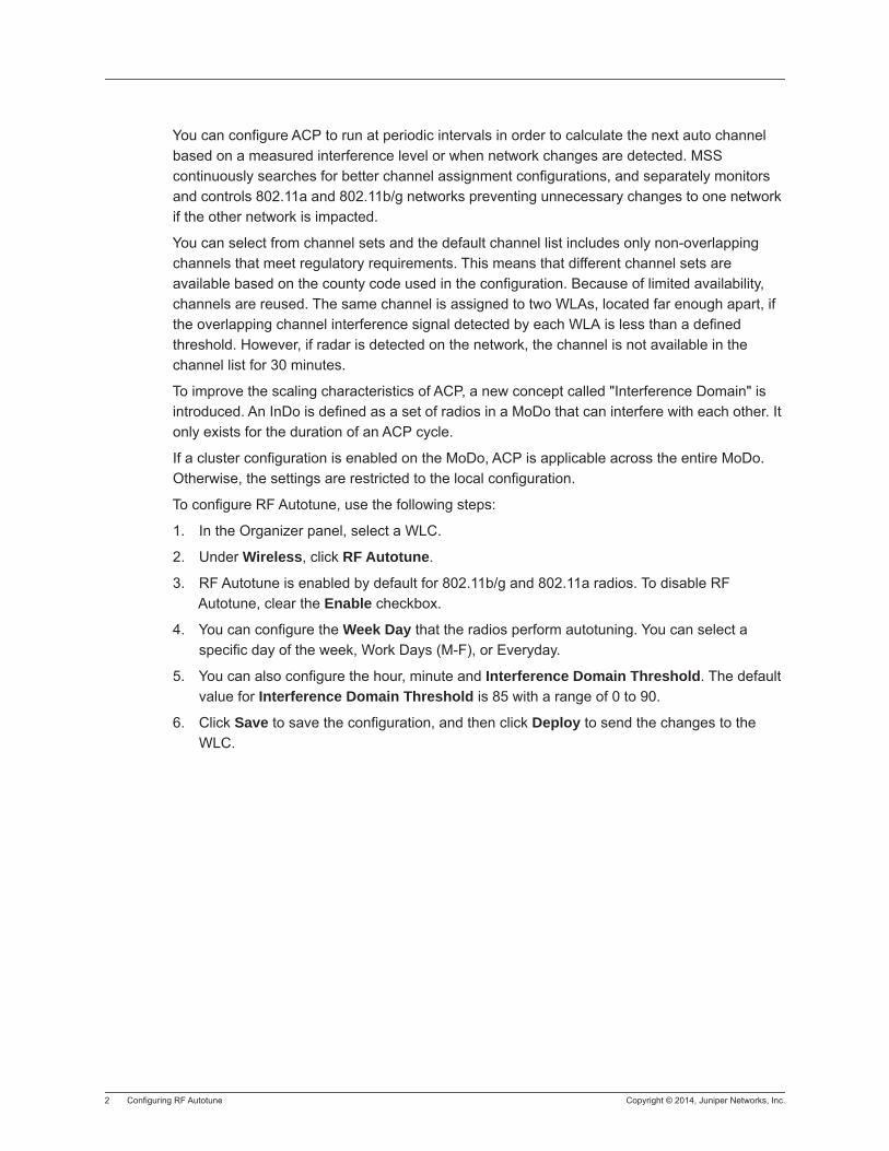
2 Configuring RF Autotune Copyright © 2014, Juniper Networks, Inc.
You can configure ACP to run at periodic intervals in order to calculate the next auto channel based on a measured interference level or when network changes are detected. MSS continuously searches for better channel assignment configurations, and separately monitors and controls 802.11a and 802.11b/g networks preventing unnecessary changes to one network if the other network is impacted.
You can select from channel sets and the default channel list includes only non-overlapping channels that meet regulatory requirements. This means that different channel sets are available based on the county code used in the configuration. Because of limited availability, channels are reused. The same channel is assigned to two WLAs, located far enough apart, if the overlapping channel interference signal detected by each WLA is less than a defined threshold. However, if radar is detected on the network, the channel is not available in the channel list for 30 minutes.
To improve the scaling characteristics of ACP, a new concept called "Interference Domain" is introduced. An InDo is defined as a set of radios in a MoDo that can interfere with each other. It only exists for the duration of an ACP cycle.
If a cluster configuration is enabled on the MoDo, ACP is applicable across the entire MoDo. Otherwise, the settings are restricted to the local configuration.
To configure RF Autotune, use the following steps:
1. In the Organizer panel, select a WLC.
2. Under Wireless, click RF Autotune.
3. RF Autotune is enabled by default for 802.11b/g and 802.11a radios. To disable RF Autotune, clear the Enable checkbox.
4. You can configure the Week Day that the radios perform autotuning. You can select a specific day of the week, Work Days (M-F), or Everyday.
5. You can also configure the hour, minute and Interference Domain Threshold. The default value for Interference Domain Threshold is 85 with a range of 0 to 90.
6. Click Save to save the configuration, and then click Deploy to send the changes to the WLC.
Copyright © 2014, Juniper Networks, Inc. Overview 1
AAA Configuration
AAA Configuration
Overview
If you have a WLC in your network plan, you can configure WLC AAA features using RingMaster. The following features can be configured:
Creating Users in the Local User Database
Creating a RADIUS Server
Creating a LDAP Server
Creating AAA Profiles
Creating an 802.1X Authentication Rule
Creating a MAC Access Rule
Creating a Web Authentication Rule
Creating a Open Access Rule
Creating an Admin Access Rule
Creating a Console Access Rule
Creating RADIUS Proxy Client
Creating a Location Policy Rule
Creating a Mobility Profile
Configuring Device Fingerprinting
Configuring Bonjour Services
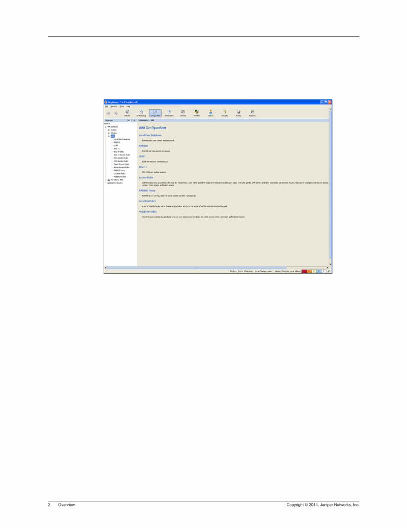
2 Overview Copyright © 2014, Juniper Networks, Inc.
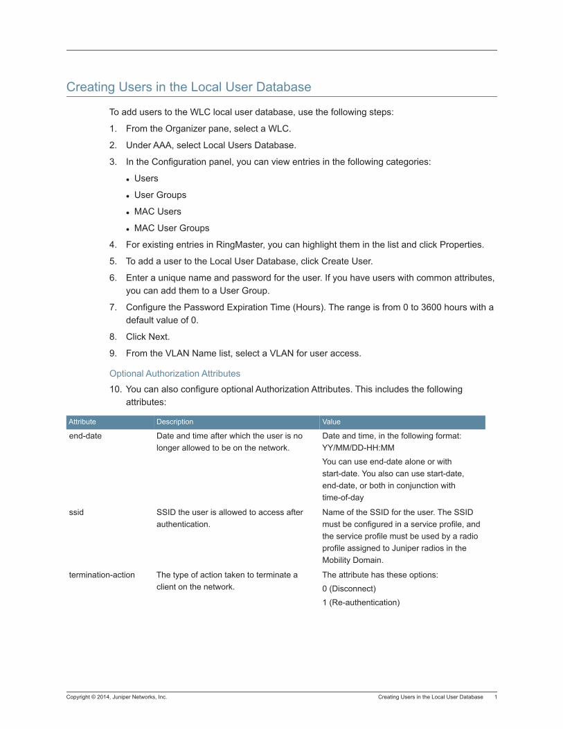
Copyright © 2014, Juniper Networks, Inc. Creating Users in the Local User Database 1
Creating Users in the Local User Database
To add users to the WLC local user database, use the following steps:
1. From the Organizer pane, select a WLC.
2. Under AAA, select Local Users Database.
3. In the Configuration panel, you can view entries in the following categories:
Users
User Groups
MAC Users
MAC User Groups
4. For existing entries in RingMaster, you can highlight them in the list and click Properties.
5. To add a user to the Local User Database, click Create User.
6. Enter a unique name and password for the user. If you have users with common attributes, you can add them to a User Group.
7. Configure the Password Expiration Time (Hours). The range is from 0 to 3600 hours with a default value of 0.
8. Click Next.
9. From the VLAN Name list, select a VLAN for user access.
Optional Authorization Attributes
10. You can also configure optional Authorization Attributes. This includes the following attributes:
Attribute Description Value
end-date Date and time after which the user is no longer allowed to be on the network.
Date and time, in the following format: YY/MM/DD-HH:MM
You can use end-date alone or with start-date. You also can use start-date, end-date, or both in conjunction with time-of-day
ssid SSID the user is allowed to access after authentication.
Name of the SSID for the user. The SSID must be configured in a service profile, and the service profile must be used by a radio profile assigned to Juniper radios in the Mobility Domain.
termination-action The type of action taken to terminate a client on the network.
The attribute has these options:
0 (Disconnect)
1 (Re-authentication)
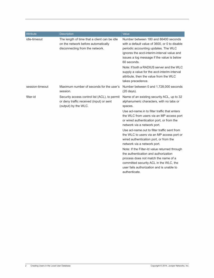
2 Creating Users in the Local User Database Copyright © 2014, Juniper Networks, Inc.
idle-timeout The length of time that a client can be idle on the network before automatically disconnecting from the network.
Number between 180 and 86400 seconds with a default value of 3600, or 0 to disable periodic accounting updates. The WLC ignores the acct-interim-interval value and issues a log message if the value is below 60 seconds.
Note: If both a RADIUS server and the WLC supply a value for the acct-interim-interval attribute, then the value from the WLC takes precedence.
session-timeout Maximum number of seconds for the user’s session.
Number between 0 and 1,728,000 seconds (20 days).
filter-id Security access control list (ACL), to permit or deny traffic received (input) or sent (output) by the WLC.
Name of an existing security ACL, up to 32 alphanumeric characters, with no tabs or spaces.
Use acl-name.in to filter traffic that enters the WLC from users via an MP access port or wired authentication port, or from the network via a network port.
Use acl-name.out to filter traffic sent from the WLC to users via an MP access port or wired authentication port, or from the network via a network port.
Note: If the Filter-Id value returned through the authentication and authorization process does not match the name of a committed security ACL in the WLC, the user fails authorization and is unable to authenticate.
Attribute Description Value
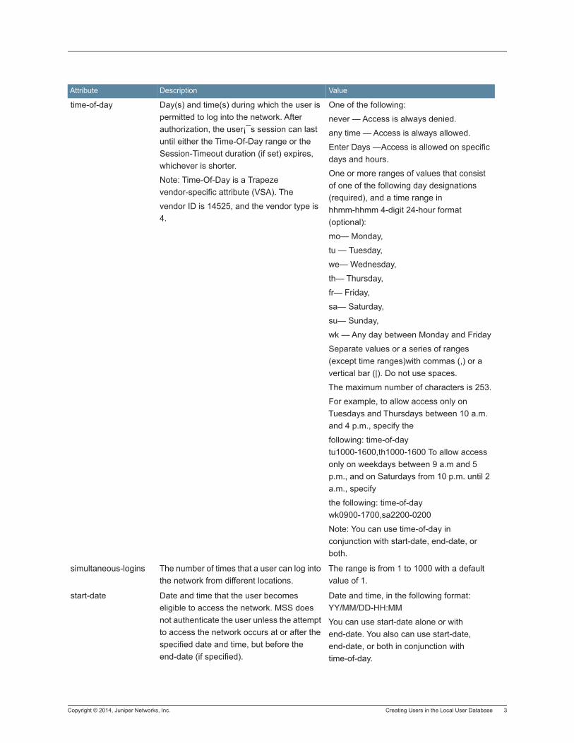
Copyright © 2014, Juniper Networks, Inc. Creating Users in the Local User Database 3
time-of-day Day(s) and time(s) during which the user is permitted to log into the network. After authorization, the user¡¯s session can last until either the Time-Of-Day range or the Session-Timeout duration (if set) expires, whichever is shorter.
Note: Time-Of-Day is a Trapeze vendor-specific attribute (VSA). The
vendor ID is 14525, and the vendor type is 4.
One of the following:
never — Access is always denied.
any time — Access is always allowed.
Enter Days —Access is allowed on specific days and hours.
One or more ranges of values that consist of one of the following day designations (required), and a time range in hhmm-hhmm 4-digit 24-hour format (optional):
mo— Monday,
tu — Tuesday,
we— Wednesday,
th— Thursday,
fr— Friday,
sa— Saturday,
su— Sunday,
wk — Any day between Monday and Friday
Separate values or a series of ranges (except time ranges)with commas (,) or a vertical bar (|). Do not use spaces.
The maximum number of characters is 253.
For example, to allow access only on Tuesdays and Thursdays between 10 a.m. and 4 p.m., specify the
following: time-of-day tu1000-1600,th1000-1600 To allow access only on weekdays between 9 a.m and 5 p.m., and on Saturdays from 10 p.m. until 2 a.m., specify
the following: time-of-day wk0900-1700,sa2200-0200
Note: You can use time-of-day in conjunction with start-date, end-date, or both.
simultaneous-logins The number of times that a user can log into the network from different locations.
The range is from 1 to 1000 with a default value of 1.
start-date Date and time that the user becomes eligible to access the network. MSS does not authenticate the user unless the attempt to access the network occurs at or after the specified date and time, but before the end-date (if specified).
Date and time, in the following format: YY/MM/DD-HH:MM
You can use start-date alone or with end-date. You also can use start-date, end-date, or both in conjunction with time-of-day.
Attribute Description Value

4 Creating Users in the Local User Database Copyright © 2014, Juniper Networks, Inc.
mobility-profile Mobility Profile attribute forth user. (For more information, see Viewing Mobility Profiles.)
Note: Mobility-Profile is a Trapeze vendor-specific attribute (VSA). The vendor ID is 14525, the vendor type is 2.
Name of an existing Mobility Profile
Note: If the Mobility Profile feature is enabled, and a user is assigned the name of a nonexistent Mobility Profile on the WLC, the user is denied access.
acct-interim-interval Interval in seconds between accounting updates, if accounting is enabled and the Start-Stop record type is specified.
Select Enable Updates and then a number between 180 and 3,600 seconds, or 0 to disable periodic accounting updates.
The WLC ignores the acct-interim-interval value and issues a log message if the value is below 60 seconds.
Note: If both a RADIUS server and the WLC supply a value for the acct-interim-interval attribute, then the value from the WLC takes precedence.
qos-profile You can assign a user to a specific QoS profile.
Select the profile from the list of configured QoS Profiles.
url URL to which the user is redirected after successful WebAAA .
Web URL, in standard format. For example:
http://www.example.com
Note: You must include the http:// portion.
Attribute Description Value
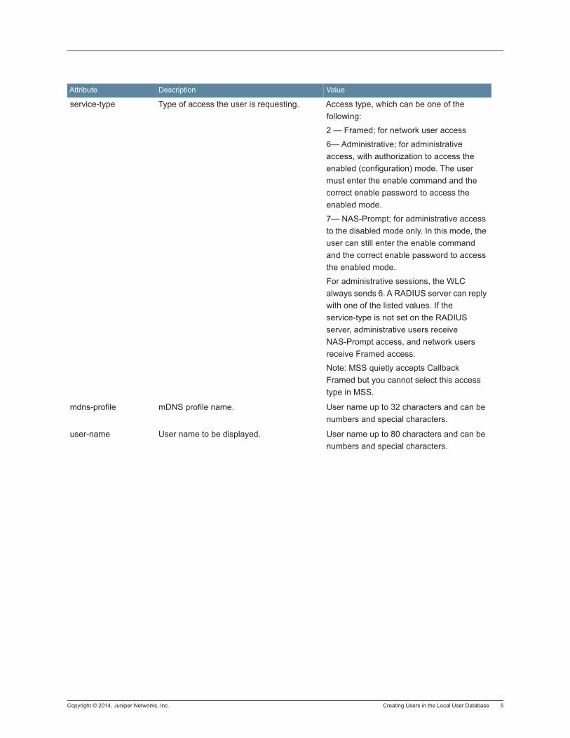
Copyright © 2014, Juniper Networks, Inc. Creating Users in the Local User Database 5
service-type Type of access the user is requesting. Access type, which can be one of the following:
2 — Framed; for network user access
6— Administrative; for administrative access, with authorization to access the enabled (configuration) mode. The user must enter the enable command and the correct enable password to access the enabled mode.
7— NAS-Prompt; for administrative access to the disabled mode only. In this mode, the user can still enter the enable command and the correct enable password to access the enabled mode.
For administrative sessions, the WLC always sends 6. A RADIUS server can reply with one of the listed values. If the service-type is not set on the RADIUS server, administrative users receive NAS-Prompt access, and network users receive Framed access.
Note: MSS quietly accepts Callback Framed but you cannot select this access type in MSS.
mdns-profile mDNS profile name. User name up to 32 characters and can be numbers and special characters.
user-name User name to be displayed. User name up to 80 characters and can be numbers and special characters.
Attribute Description Value
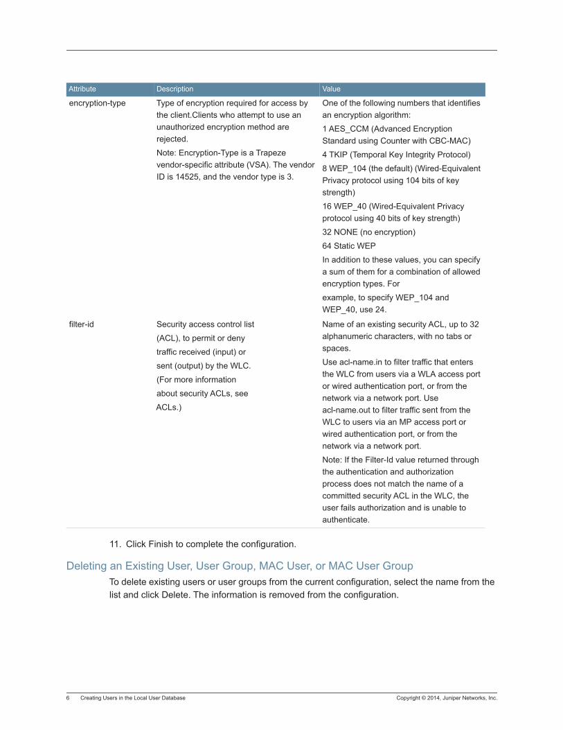
6 Creating Users in the Local User Database Copyright © 2014, Juniper Networks, Inc.
11. Click Finish to complete the configuration.
Deleting an Existing User, User Group, MAC User, or MAC User GroupTo delete existing users or user groups from the current configuration, select the name from the list and click Delete. The information is removed from the configuration.
encryption-type Type of encryption required for access by the client.Clients who attempt to use an unauthorized encryption method are rejected.
Note: Encryption-Type is a Trapeze vendor-specific attribute (VSA). The vendor ID is 14525, and the vendor type is 3.
One of the following numbers that identifies an encryption algorithm:
1 AES_CCM (Advanced Encryption Standard using Counter with CBC-MAC)
4 TKIP (Temporal Key Integrity Protocol)
8 WEP_104 (the default) (Wired-Equivalent Privacy protocol using 104 bits of key strength)
16 WEP_40 (Wired-Equivalent Privacy protocol using 40 bits of key strength)
32 NONE (no encryption)
64 Static WEP
In addition to these values, you can specify a sum of them for a combination of allowed encryption types. For
example, to specify WEP_104 and WEP_40, use 24.
filter-id Security access control list
(ACL), to permit or deny
traffic received (input) or
sent (output) by the WLC.
(For more information
about security ACLs, see
ACLs.)
Name of an existing security ACL, up to 32 alphanumeric characters, with no tabs or spaces.
Use acl-name.in to filter traffic that enters the WLC from users via a WLA access port or wired authentication port, or from the network via a network port. Use acl-name.out to filter traffic sent from the WLC to users via an MP access port or wired authentication port, or from the network via a network port.
Note: If the Filter-Id value returned through the authentication and authorization process does not match the name of a committed security ACL in the WLC, the user fails authorization and is unable to authenticate.
Attribute Description Value
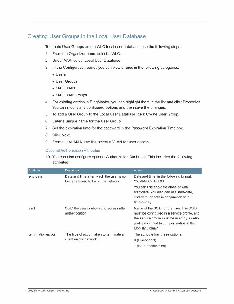
Copyright © 2014, Juniper Networks, Inc. Creating User Groups in the Local User Database 1
Creating User Groups in the Local User Database
To create User Groups on the WLC local user database, use the following steps:
1. From the Organizer pane, select a WLC.
2. Under AAA, select Local User Database.
3. In the Configuration panel, you can view entries in the following categories:
Users
User Groups
MAC Users
MAC User Groups
4. For existing entries in RingMaster, you can highlight them in the list and click Properties. You can modify any configured options and then save the changes.
5. To add a User Group to the Local User Database, click Create User Group.
6. Enter a unique name for the User Group.
7. Set the expiration time for the password in the Password Expiration Time box.
8. Click Next.
9. From the VLAN Name list, select a VLAN for user access.
Optional Authorization Attributes
10. You can also configure optional Authorization Attributes. This includes the following attributes:
Attribute Description Value
end-date Date and time after which the user is no longer allowed to be on the network.
Date and time, in the following format: YY/MM/DD-HH:MM
You can use end-date alone or with start-date. You also can use start-date, end-date, or both in conjunction with time-of-day
ssid SSID the user is allowed to access after authentication.
Name of the SSID for the user. The SSID must be configured in a service profile, and the service profile must be used by a radio profile assigned to Juniper radios in the Mobility Domain.
termination-action The type of action taken to terminate a client on the network.
The attribute has these options:
0 (Disconnect)
1 (Re-authentication)

2 Creating User Groups in the Local User Database Copyright © 2014, Juniper Networks, Inc.
idle-timeout The length of time that a client can be idle on the network before automatically disconnecting from the network.
Number between 180 and 86400, or 0 to disable periodic accounting updates. The default value is 3600 seconds. The WLC ignores the acct-interim-interval value and issues a log message if the value is below 60 seconds.
Note: If both a RADIUS server and the WLC supply a value for the acct-interim-interval attribute, then the value from the WLC takes precedence.
session-timeout Maximum number of seconds for the user’s session.
Number between 0 and 1,728,000 seconds (20 days).
filter-id Security access control list (ACL), to permit or deny traffic received (input) or sent (output) by the WLC.
Name of an existing security ACL, up to 32 alphanumeric characters, with no tabs or spaces.
Use acl-name.in to filter traffic that enters the WLC from users via an MP access port or wired authentication port, or from the network via a network port.
Use acl-name.out to filter traffic sent from the WLC to users via an MP access port or wired authentication port, or from the network via a network port.
Note: If the Filter-Id value returned through the authentication and authorization process does not match the name of a committed security ACL in the WLC, the user fails authorization and is unable to authenticate.
Attribute Description Value
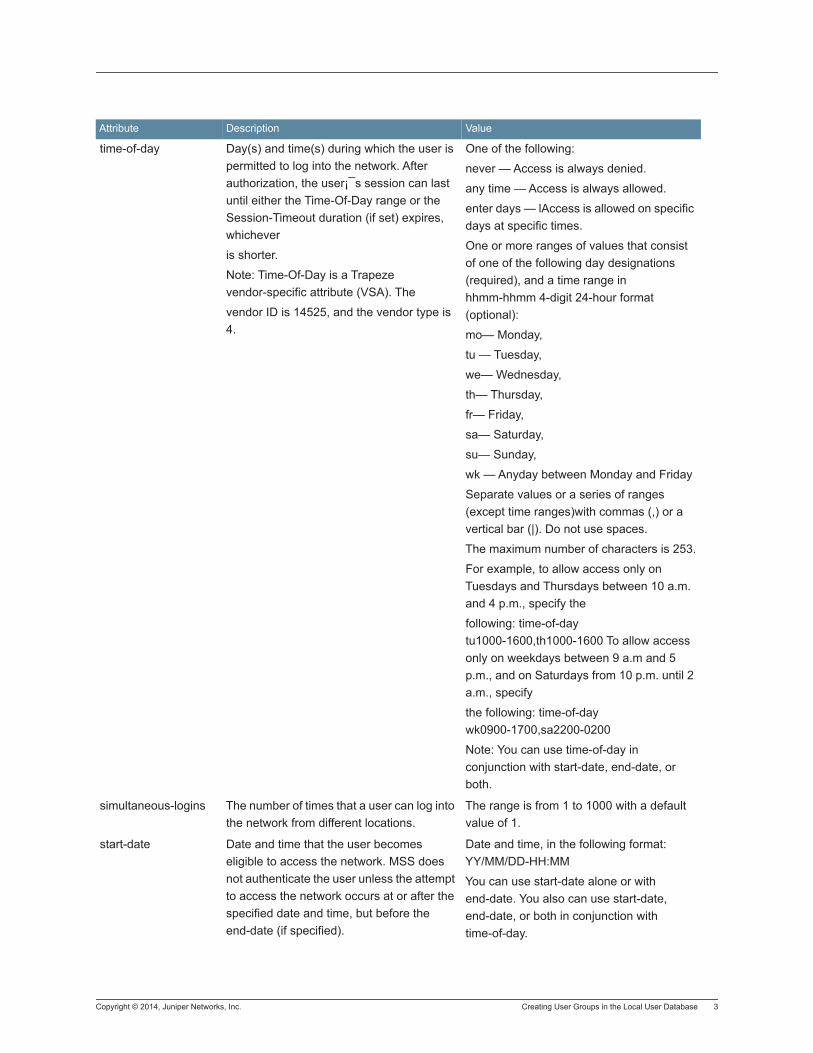
Copyright © 2014, Juniper Networks, Inc. Creating User Groups in the Local User Database 3
time-of-day Day(s) and time(s) during which the user is permitted to log into the network. After authorization, the user¡¯s session can last until either the Time-Of-Day range or the Session-Timeout duration (if set) expires, whichever
is shorter.
Note: Time-Of-Day is a Trapeze vendor-specific attribute (VSA). The
vendor ID is 14525, and the vendor type is 4.
One of the following:
never — Access is always denied.
any time — Access is always allowed.
enter days — lAccess is allowed on specific days at specific times.
One or more ranges of values that consist of one of the following day designations (required), and a time range in hhmm-hhmm 4-digit 24-hour format (optional):
mo— Monday,
tu — Tuesday,
we— Wednesday,
th— Thursday,
fr— Friday,
sa— Saturday,
su— Sunday,
wk — Anyday between Monday and Friday
Separate values or a series of ranges (except time ranges)with commas (,) or a vertical bar (|). Do not use spaces.
The maximum number of characters is 253.
For example, to allow access only on Tuesdays and Thursdays between 10 a.m. and 4 p.m., specify the
following: time-of-day tu1000-1600,th1000-1600 To allow access only on weekdays between 9 a.m and 5 p.m., and on Saturdays from 10 p.m. until 2 a.m., specify
the following: time-of-day wk0900-1700,sa2200-0200
Note: You can use time-of-day in conjunction with start-date, end-date, or both.
simultaneous-logins The number of times that a user can log into the network from different locations.
The range is from 1 to 1000 with a default value of 1.
start-date Date and time that the user becomes eligible to access the network. MSS does not authenticate the user unless the attempt to access the network occurs at or after the specified date and time, but before the end-date (if specified).
Date and time, in the following format: YY/MM/DD-HH:MM
You can use start-date alone or with end-date. You also can use start-date, end-date, or both in conjunction with time-of-day.
Attribute Description Value
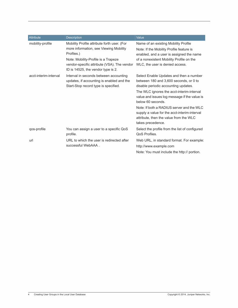
4 Creating User Groups in the Local User Database Copyright © 2014, Juniper Networks, Inc.
mobility-profile Mobility Profile attribute forth user. (For more information, see Viewing Mobility Profiles.)
Note: Mobility-Profile is a Trapeze vendor-specific attribute (VSA). The vendor ID is 14525, the vendor type is 2.
Name of an existing Mobility Profile
Note: If the Mobility Profile feature is enabled, and a user is assigned the name of a nonexistent Mobility Profile on the WLC, the user is denied access.
acct-interim-interval Interval in seconds between accounting updates, if accounting is enabled and the Start-Stop record type is specified.
Select Enable Updates and then a number between 180 and 3,600 seconds, or 0 to disable periodic accounting updates.
The WLC ignores the acct-interim-interval value and issues log message if the value is below 60 seconds.
Note: If both a RADIUS server and the WLC supply a value for the acct-interim-interval attribute, then the value from the WLC takes precedence.
qos-profile You can assign a user to a specific QoS profile.
Select the profile from the list of configured QoS Profiles.
url URL to which the user is redirected after successful WebAAA .
Web URL, in standard format. For example:
http://www.example.com
Note: You must include the http:// portion.
Attribute Description Value

Copyright © 2014, Juniper Networks, Inc. Creating User Groups in the Local User Database 5
service-type Type of access the user is requesting. Access type, which can be one of the following:
2 — Framed; for network user access
6— Administrative; for administrative access, with authorization to access the enabled (configuration) mode. The user must enter the enable command and the correct enable password to access the enabled mode.
7— NAS-Prompt; for administrative access to the nonenabled mode only. In this mode, the user can still enter the enable command and the correct enable password to access the enabled mode.
For administrative sessions, the WLC always sends 6. A RADIUS server can reply with one of the listed values. If the service-type is not set on the RADIUS server, administrative users receive NAS-Prompt access, and network users receive Framed access.
Note: MSS quietly accepts Callback Framed but you cannot select this access type in MSS.
mdns-profile mDNS profile name. mDNS profile name up to 32 characters and can be numbers and special characters.
user-name User name to be displayed. User name up to 80 characters and can be numbers and special characters.
Attribute Description Value

6 Creating User Groups in the Local User Database Copyright © 2014, Juniper Networks, Inc.
11. Click Next.
12. From the list of Available Users, select desired users and click Add to move them into the Current Users group.
13. Click Finish to complete the configuration.
encryption-type Type of encryption required for access by the client.Clients who attempt to use an unauthorized encryption method are rejected.
Note: Encryption-Type is a Trapeze vendor-specific attribute (VSA). The vendor ID is 14525, and the vendor type is 3.
One of the following numbers that identifies an encryption algorithm:
1 AES_CCM (Advanced Encryption Standard using Counter with CBC-MAC)
4 TKIP (Temporal Key Integrity Protocol)
8 WEP_104 (the default) (Wired-Equivalent Privacy protocol using 104 bits of key strength)
16 WEP_40 (Wired-Equivalent Privacy protocol using 40 bits of key strength)
32 NONE (no encryption)
64 Static WEP
In addition to these values, you can specify a sum of them for a combination of allowed encryption types. For example, to specify WEP_104 and WEP_40, use 24.
filter-id Security access control list
(ACL), to permit or deny
traffic received (input) or
sent (output) by the WLC.
(For more information
about security ACLs, see
ACLs.)
Name of an existing security ACL, up to 32 alphanumeric
characters, with no tabs or spaces.
. Use acl-name.in to filter traffic that enters the WLC from users
via an MP access port or wired authentication port, or from the
network via a network port.
. Use acl-name.out to filter traffic sent from the WLC to users via
an MP access port or wired authentication port, or from the
network via a network port.
Note: If the Filter-Id value returned through the authentication
and authorization process does not match the name of a
committed security ACL in the WLC, the user fails authorization
and is unable to authenticate.
Attribute Description Value

Copyright © 2014, Juniper Networks, Inc. Creating User Groups in the Local User Database 7
Deleting an Existing User, User Group, MAC User, or MAC User GroupTo delete existing users or user groups from the current configuration, select the name from the list and click Delete. The information is removed from the configuration.

8 Creating User Groups in the Local User Database Copyright © 2014, Juniper Networks, Inc.
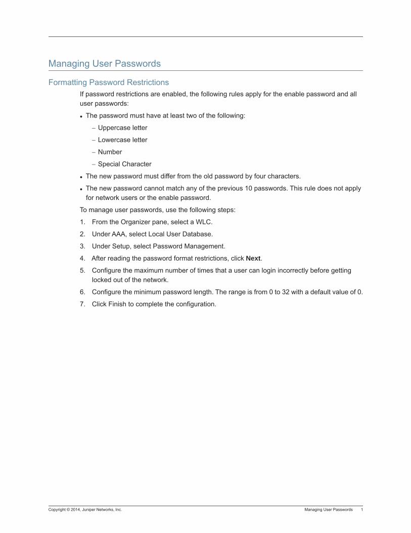
Copyright © 2014, Juniper Networks, Inc. Managing User Passwords 1
Managing User Passwords
Formatting Password RestrictionsIf password restrictions are enabled, the following rules apply for the enable password and all user passwords:
The password must have at least two of the following:
− Uppercase letter
− Lowercase letter
− Number
− Special Character
The new password must differ from the old password by four characters.
The new password cannot match any of the previous 10 passwords. This rule does not apply for network users or the enable password.
To manage user passwords, use the following steps:
1. From the Organizer pane, select a WLC.
2. Under AAA, select Local User Database.
3. Under Setup, select Password Management.
4. After reading the password format restrictions, click Next.
5. Configure the maximum number of times that a user can login incorrectly before getting locked out of the network.
6. Configure the minimum password length. The range is from 0 to 32 with a default value of 0.
7. Click Finish to complete the configuration.

2 Managing User Passwords Copyright © 2014, Juniper Networks, Inc.
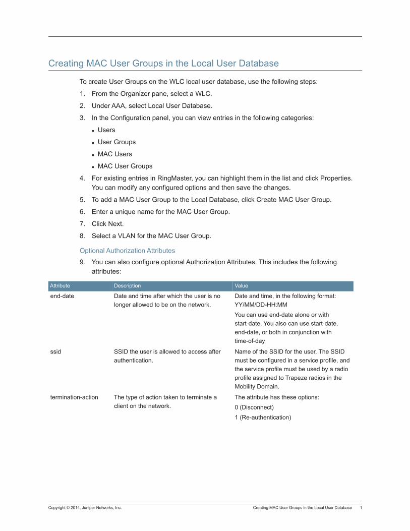
Copyright © 2014, Juniper Networks, Inc. Creating MAC User Groups in the Local User Database 1
Creating MAC User Groups in the Local User Database
To create User Groups on the WLC local user database, use the following steps:
1. From the Organizer pane, select a WLC.
2. Under AAA, select Local User Database.
3. In the Configuration panel, you can view entries in the following categories:
Users
User Groups
MAC Users
MAC User Groups
4. For existing entries in RingMaster, you can highlight them in the list and click Properties. You can modify any configured options and then save the changes.
5. To add a MAC User Group to the Local Database, click Create MAC User Group.
6. Enter a unique name for the MAC User Group.
7. Click Next.
8. Select a VLAN for the MAC User Group.
Optional Authorization Attributes
9. You can also configure optional Authorization Attributes. This includes the following attributes:
Attribute Description Value
end-date Date and time after which the user is no longer allowed to be on the network.
Date and time, in the following format: YY/MM/DD-HH:MM
You can use end-date alone or with start-date. You also can use start-date, end-date, or both in conjunction with time-of-day
ssid SSID the user is allowed to access after authentication.
Name of the SSID for the user. The SSID must be configured in a service profile, and the service profile must be used by a radio profile assigned to Trapeze radios in the Mobility Domain.
termination-action The type of action taken to terminate a client on the network.
The attribute has these options:
0 (Disconnect)
1 (Re-authentication)
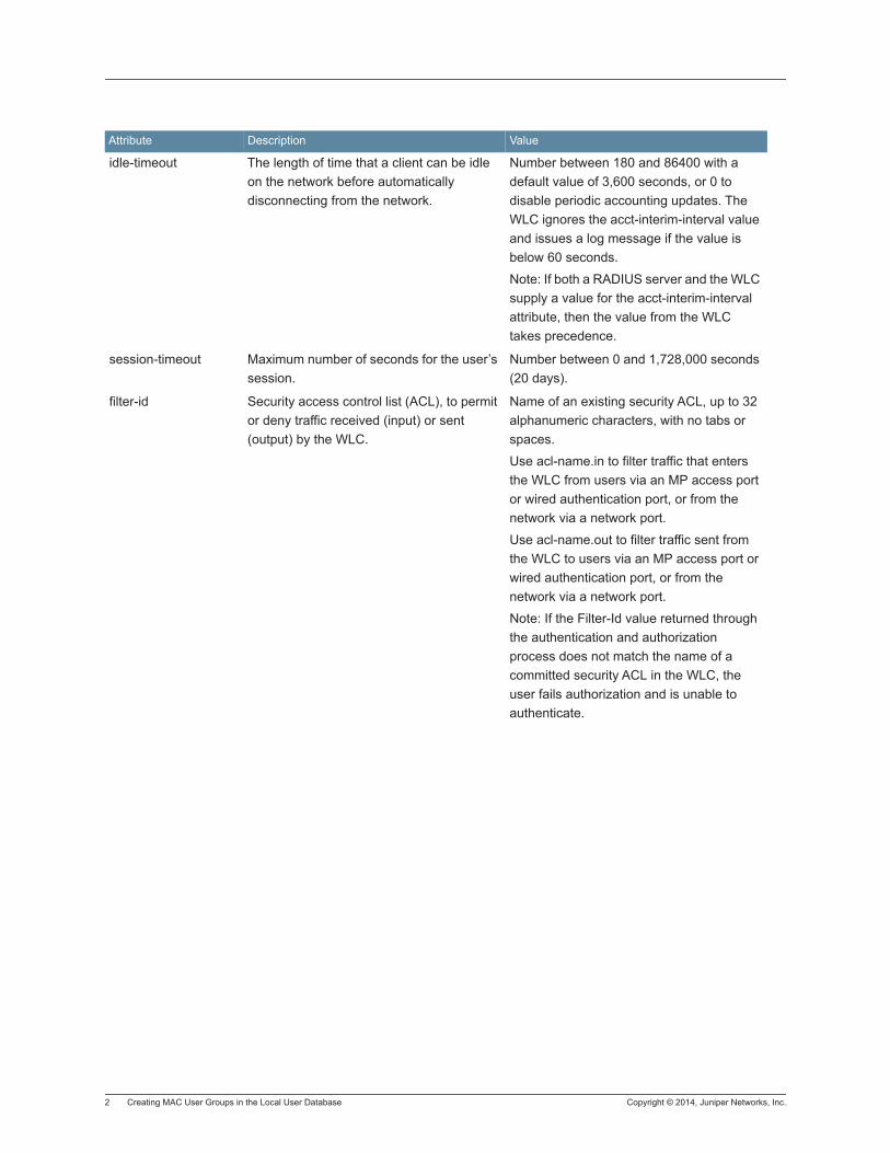
2 Creating MAC User Groups in the Local User Database Copyright © 2014, Juniper Networks, Inc.
idle-timeout The length of time that a client can be idle on the network before automatically disconnecting from the network.
Number between 180 and 86400 with a default value of 3,600 seconds, or 0 to disable periodic accounting updates. The WLC ignores the acct-interim-interval value and issues a log message if the value is below 60 seconds.
Note: If both a RADIUS server and the WLC supply a value for the acct-interim-interval attribute, then the value from the WLC takes precedence.
session-timeout Maximum number of seconds for the user’s session.
Number between 0 and 1,728,000 seconds (20 days).
filter-id Security access control list (ACL), to permit or deny traffic received (input) or sent (output) by the WLC.
Name of an existing security ACL, up to 32 alphanumeric characters, with no tabs or spaces.
Use acl-name.in to filter traffic that enters the WLC from users via an MP access port or wired authentication port, or from the network via a network port.
Use acl-name.out to filter traffic sent from the WLC to users via an MP access port or wired authentication port, or from the network via a network port.
Note: If the Filter-Id value returned through the authentication and authorization process does not match the name of a committed security ACL in the WLC, the user fails authorization and is unable to authenticate.
Attribute Description Value

Copyright © 2014, Juniper Networks, Inc. Creating MAC User Groups in the Local User Database 3
time-of-day Day(s) and time(s) during which the user is permitted to log into the network. After authorization, the user¡¯s session can last until either the Time-Of-Day range or the Session-Timeout duration (if set) expires, whichever
is shorter.
Note: Time-Of-Day is a Trapeze vendor-specific attribute (VSA). The
vendor ID is 14525, and the vendor type is 4.
One of the following:
never — Access is always denied.
any time — Access is always allowed.
enter days —Access is allowed on specific days at specific times.
One or more ranges of values that consist of one of the following day designations (required), and a time range in hhmm-hhmm 4-digit 24-hour format (optional):
mo— Monday,
tu — Tuesday,
we— Wednesday,
th— Thursday,
fr— Friday,
sa— Saturday,
su— Sunday,
wk — Anyday between Monday and Friday
Separate values or a series of ranges (except time Renfrewshire commas (,) or a vertical bar (|). Do not use spaces.
The maximum number of characters is 253.
For example, to allow access only on Tuesdays and Thursdays between 10 a.m. and 4 p.m., specify the
following: time-of-day tu1000-1600,th1000-1600 To allow access only on weekdays between 9 a.m and 5 p.m., and on Saturdays from 10 p.m. until 2 a.m., specify
the following: time-of-day wk0900-1700,sa2200-0200
Note: You can use time-of-day in conjunction with start-date, end-date, or both.
simultaneous-logins The number of times that a user can log into the network from different locations.
The range is from 1 to 1000 with a default value of 1.
start-date Date and time that the user becomes eligible to access the network. MSS does not authenticate the user unless the attempt to access the network occurs at or after the specified date and time, but before the end-date (if specified).
Date and time, in the following format: YY/MM/DD-HH:MM
You can use start-date alone or with end-date. You also can use start-date, end-date, or both in conjunction with time-of-day.
Attribute Description Value

4 Creating MAC User Groups in the Local User Database Copyright © 2014, Juniper Networks, Inc.
mobility-profile Mobility Profile attribute forth user. (For more information, see Viewing Mobility Profiles.)
Note: Mobility-Profile is a Trapeze vendor-specific attribute (VSA). The vendor ID is 14525, the vendor type is 2.
Name of an existing Mobility Profile
Note: If the Mobility Profile feature is enabled, and a user is assigned the name of a nonexistent Mobility Profile on the WLC, the user is denied access.
acct-interim-interval Interval in seconds between accounting updates, if accounting is enabled and the Start-Stop record type is specified.
Select Enable Updates and then a number between 180 and 3,600 seconds, or 0 to disable periodic accounting updates.
The WLC ignores the acct-interim-interval value and issues log message if the value is below 60 seconds.
Note: If both a RADIUS server and the WLC supply a value for the acct-interim-interval attribute, then the value from the WLC takes precedence.
qos-profile You can assign a user to a specific QoS profile.
Select the profile from the list of configured QoS Profiles.
url URL to which the user is redirected after successful WebAAA .
Web URL, in standard format. For example:
http://www.example.com
Note: You must include the http:// portion.
Attribute Description Value
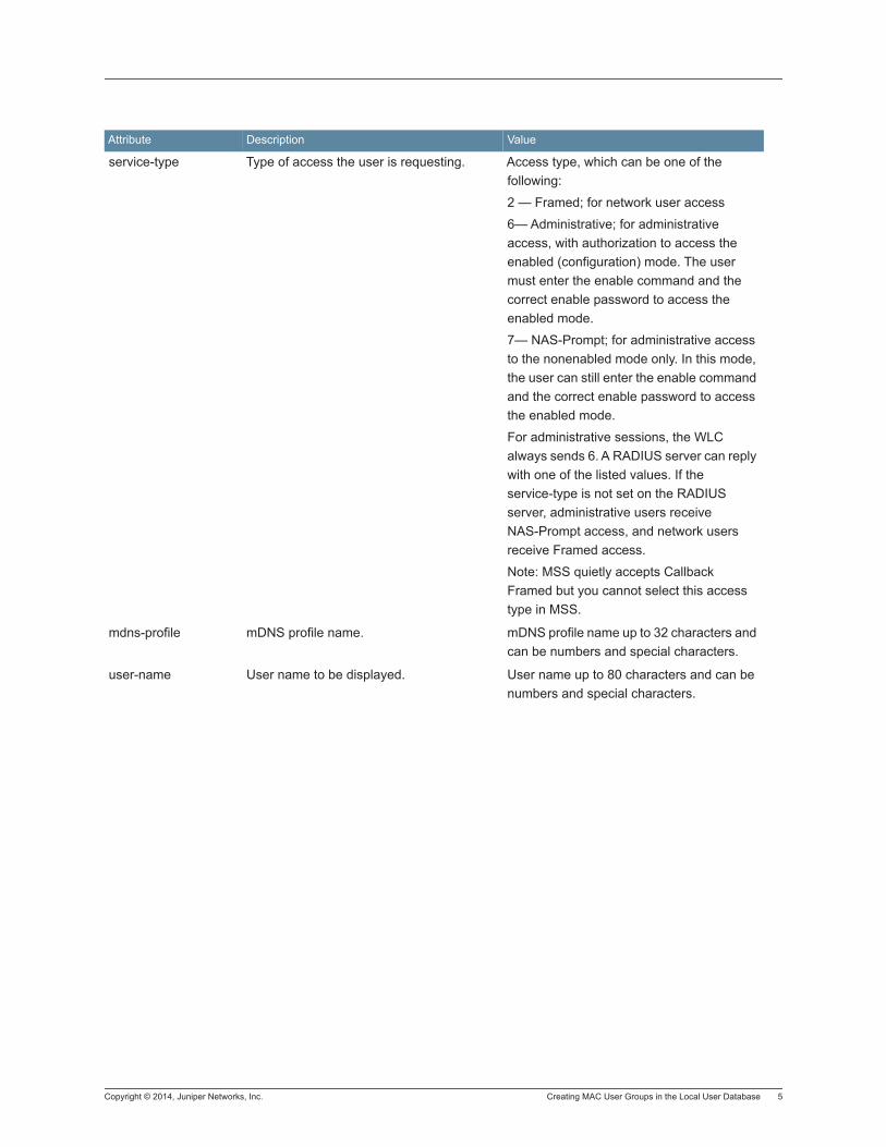
Copyright © 2014, Juniper Networks, Inc. Creating MAC User Groups in the Local User Database 5
service-type Type of access the user is requesting. Access type, which can be one of the following:
2 — Framed; for network user access
6— Administrative; for administrative access, with authorization to access the enabled (configuration) mode. The user must enter the enable command and the correct enable password to access the enabled mode.
7— NAS-Prompt; for administrative access to the nonenabled mode only. In this mode, the user can still enter the enable command and the correct enable password to access the enabled mode.
For administrative sessions, the WLC always sends 6. A RADIUS server can reply with one of the listed values. If the service-type is not set on the RADIUS server, administrative users receive NAS-Prompt access, and network users receive Framed access.
Note: MSS quietly accepts Callback Framed but you cannot select this access type in MSS.
mdns-profile mDNS profile name. mDNS profile name up to 32 characters and can be numbers and special characters.
user-name User name to be displayed. User name up to 80 characters and can be numbers and special characters.
Attribute Description Value
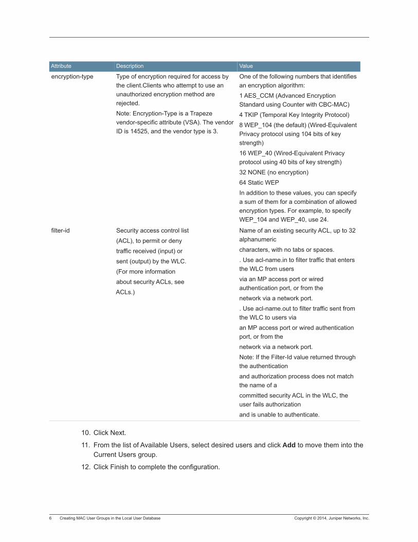
6 Creating MAC User Groups in the Local User Database Copyright © 2014, Juniper Networks, Inc.
10. Click Next.
11. From the list of Available Users, select desired users and click Add to move them into the Current Users group.
12. Click Finish to complete the configuration.
encryption-type Type of encryption required for access by the client.Clients who attempt to use an unauthorized encryption method are rejected.
Note: Encryption-Type is a Trapeze vendor-specific attribute (VSA). The vendor ID is 14525, and the vendor type is 3.
One of the following numbers that identifies an encryption algorithm:
1 AES_CCM (Advanced Encryption Standard using Counter with CBC-MAC)
4 TKIP (Temporal Key Integrity Protocol)
8 WEP_104 (the default) (Wired-Equivalent Privacy protocol using 104 bits of key strength)
16 WEP_40 (Wired-Equivalent Privacy protocol using 40 bits of key strength)
32 NONE (no encryption)
64 Static WEP
In addition to these values, you can specify a sum of them for a combination of allowed encryption types. For example, to specify WEP_104 and WEP_40, use 24.
filter-id Security access control list
(ACL), to permit or deny
traffic received (input) or
sent (output) by the WLC.
(For more information
about security ACLs, see
ACLs.)
Name of an existing security ACL, up to 32 alphanumeric
characters, with no tabs or spaces.
. Use acl-name.in to filter traffic that enters the WLC from users
via an MP access port or wired authentication port, or from the
network via a network port.
. Use acl-name.out to filter traffic sent from the WLC to users via
an MP access port or wired authentication port, or from the
network via a network port.
Note: If the Filter-Id value returned through the authentication
and authorization process does not match the name of a
committed security ACL in the WLC, the user fails authorization
and is unable to authenticate.
Attribute Description Value

Copyright © 2014, Juniper Networks, Inc. Creating MAC User Groups in the Local User Database 7
Deleting an Existing User, User Group, MAC User, or MAC User GroupTo delete existing users or user groups from the current configuration, select the name from the list and click Delete. The information is removed from the configuration.

8 Creating MAC User Groups in the Local User Database Copyright © 2014, Juniper Networks, Inc.
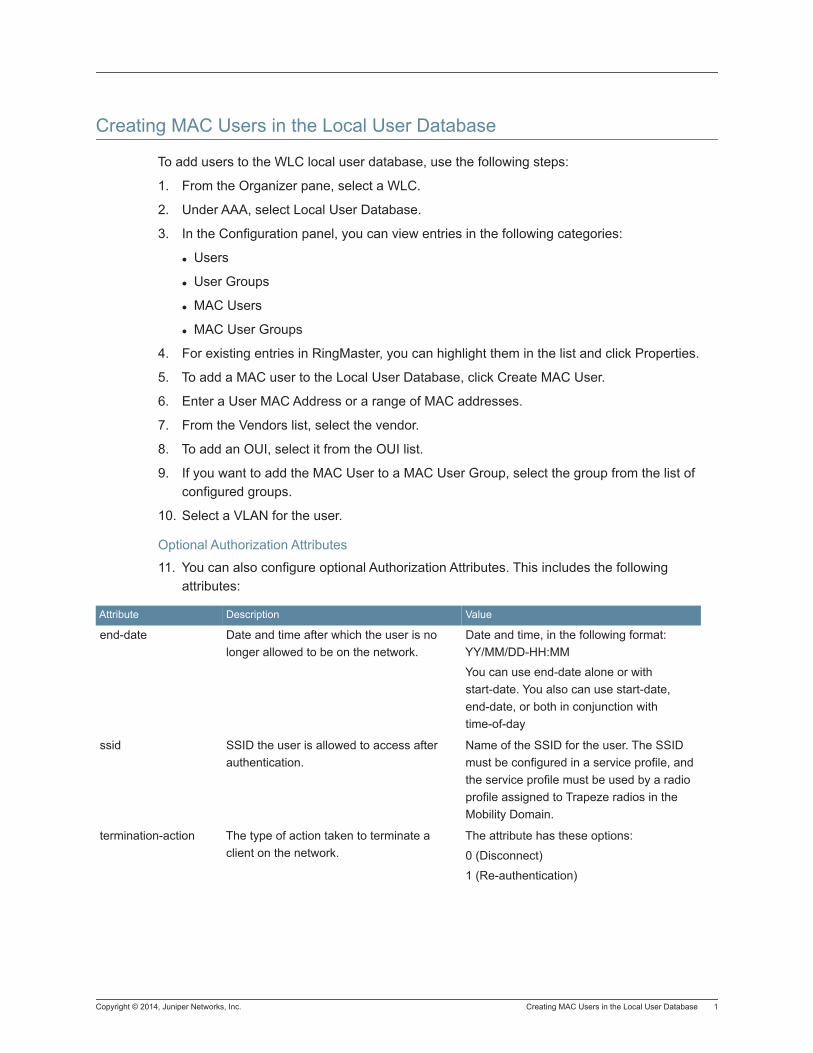
Copyright © 2014, Juniper Networks, Inc. Creating MAC Users in the Local User Database 1
Creating MAC Users in the Local User Database
To add users to the WLC local user database, use the following steps:
1. From the Organizer pane, select a WLC.
2. Under AAA, select Local User Database.
3. In the Configuration panel, you can view entries in the following categories:
Users
User Groups
MAC Users
MAC User Groups
4. For existing entries in RingMaster, you can highlight them in the list and click Properties.
5. To add a MAC user to the Local User Database, click Create MAC User.
6. Enter a User MAC Address or a range of MAC addresses.
7. From the Vendors list, select the vendor.
8. To add an OUI, select it from the OUI list.
9. If you want to add the MAC User to a MAC User Group, select the group from the list of configured groups.
10. Select a VLAN for the user.
Optional Authorization Attributes
11. You can also configure optional Authorization Attributes. This includes the following attributes:
Attribute Description Value
end-date Date and time after which the user is no longer allowed to be on the network.
Date and time, in the following format: YY/MM/DD-HH:MM
You can use end-date alone or with start-date. You also can use start-date, end-date, or both in conjunction with time-of-day
ssid SSID the user is allowed to access after authentication.
Name of the SSID for the user. The SSID must be configured in a service profile, and the service profile must be used by a radio profile assigned to Trapeze radios in the Mobility Domain.
termination-action The type of action taken to terminate a client on the network.
The attribute has these options:
0 (Disconnect)
1 (Re-authentication)
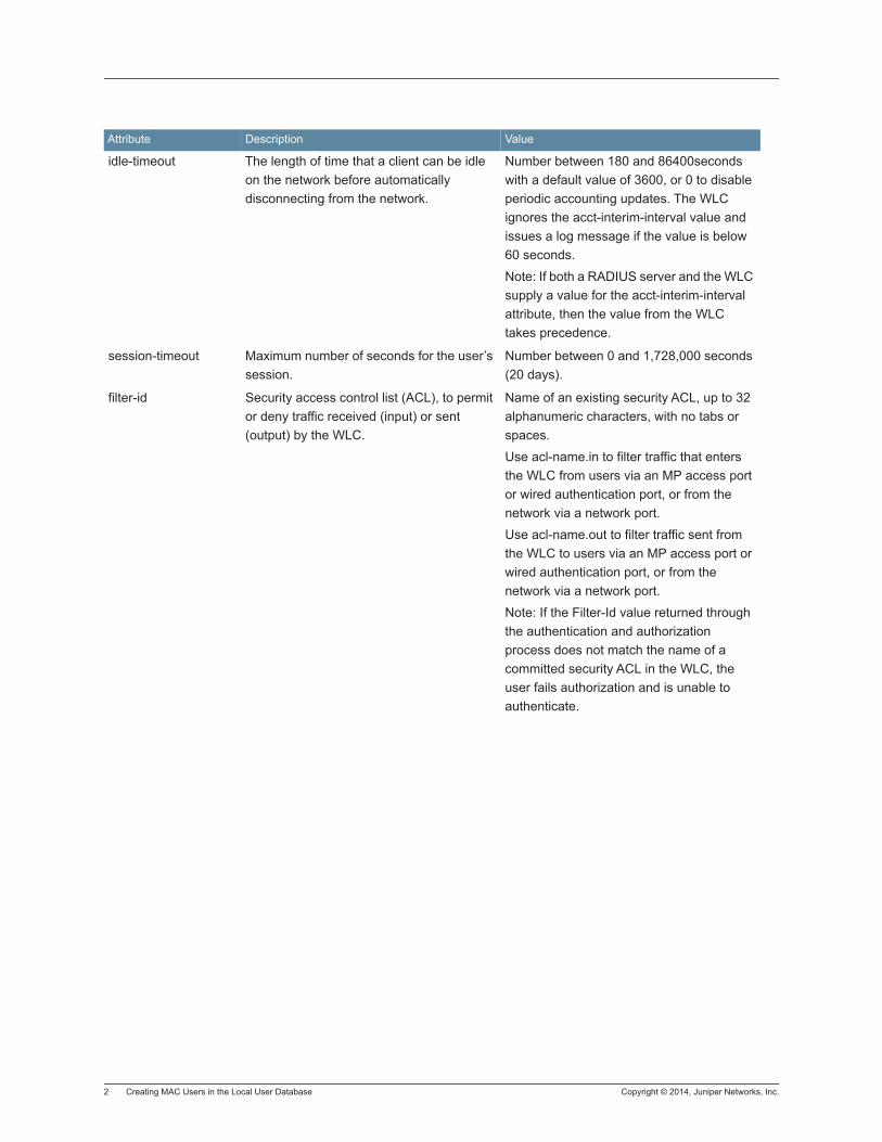
2 Creating MAC Users in the Local User Database Copyright © 2014, Juniper Networks, Inc.
idle-timeout The length of time that a client can be idle on the network before automatically disconnecting from the network.
Number between 180 and 86400seconds with a default value of 3600, or 0 to disable periodic accounting updates. The WLC ignores the acct-interim-interval value and issues a log message if the value is below 60 seconds.
Note: If both a RADIUS server and the WLC supply a value for the acct-interim-interval attribute, then the value from the WLC takes precedence.
session-timeout Maximum number of seconds for the user’s session.
Number between 0 and 1,728,000 seconds (20 days).
filter-id Security access control list (ACL), to permit or deny traffic received (input) or sent (output) by the WLC.
Name of an existing security ACL, up to 32 alphanumeric characters, with no tabs or spaces.
Use acl-name.in to filter traffic that enters the WLC from users via an MP access port or wired authentication port, or from the network via a network port.
Use acl-name.out to filter traffic sent from the WLC to users via an MP access port or wired authentication port, or from the network via a network port.
Note: If the Filter-Id value returned through the authentication and authorization process does not match the name of a committed security ACL in the WLC, the user fails authorization and is unable to authenticate.
Attribute Description Value

Copyright © 2014, Juniper Networks, Inc. Creating MAC Users in the Local User Database 3
time-of-day Day(s) and time(s) during which the user is permitted to log into the network. After authorization, the user¡¯s session can last until either the Time-Of-Day range or the Session-Timeout duration (if set) expires, whichever
is shorter.
Note: Time-Of-Day is a Trapeze vendor-specific attribute (VSA). The
vendor ID is 14525, and the vendor type is 4.
One of the following:
never — Access is always denied.
any time — Access is always allowed.
enter days —Access is allowed on specific days at specific times.
One or more ranges of values that consist of one of the following day designations (required), and a time range in hhmm-hhmm 4-digit 24-hour format (optional):
mo— Monday,
tu — Tuesday,
we— Wednesday,
th— Thursday,
fr— Friday,
sa— Saturday,
su— Sunday,
wk — Anyday between Monday and Friday
Separate values or a series of ranges (except time ranges) with commas (,) or a vertical bar (|). Do not use spaces.
The maximum number of characters is 253.
For example, to allow access only on Tuesdays and Thursdays between 10 a.m. and 4 p.m., specify the
following: time-of-day tu1000-1600,th1000-1600 To allow access only on weekdays between 9 a.m and 5 p.m., and on Saturdays from 10 p.m. until 2 a.m., specify
the following: time-of-day wk0900-1700,sa2200-0200
Note: You can use time-of-day in conjunction with start-date, end-date, or both.
simultaneous-logins The number of times that a user can log into the network from different locations.
The range is from 1 to 1000 with a default value of 1.
start-date Date and time that the user becomes eligible to access the network. MSS does not authenticate the user unless the attempt to access the network occurs at or after the specified date and time, but before the end-date (if specified).
Date and time, in the following format: YY/MM/DD-HH:MM
You can use start-date alone or with end-date. You also can use start-date, end-date, or both in conjunction with time-of-day.
Attribute Description Value

4 Creating MAC Users in the Local User Database Copyright © 2014, Juniper Networks, Inc.
mobility-profile Mobility Profile attribute forth user. (For more information, see Viewing Mobility Profiles.)
Note: Mobility-Profile is a Trapeze vendor-specific attribute (VSA). The vendor ID is 14525, the vendor type is 2.
Name of an existing Mobility Profile
Note: If the Mobility Profile feature is enabled, and a user is assigned the name of a nonexistent Mobility Profile on the WLC, the user is denied access.
acct-interim-interval Interval in seconds between accounting updates, if accounting is enabled and the Start-Stop record type is specified.
Select Enable Updates and then a number between 180 and 3,600 seconds, or 0 to disable periodic accounting updates.
The WLC ignores the acct-interim-interval value and issues a log message if the value is below 60 seconds.
Note: If both a RADIUS server and the WLC supply a value for the acct-interim-interval attribute, then the value from the WLC takes precedence.
qos-profile You can assign a user to a specific QoS profile.
Select the profile from the list of configured QoS Profiles.
url URL to which the user is redirected after successful WebAAA .
Web URL, in standard format. For example:
http://www.example.com
Note: You must include the http:// portion.
Attribute Description Value

Copyright © 2014, Juniper Networks, Inc. Creating MAC Users in the Local User Database 5
service-type Type of access the user is requesting. Access type, which can be one of the following:
2 — Framed; for network user access
6— Administrative; for administrative access, with authorization to access the enabled (configuration) mode. The user must enter the enable command and the correct enable password to access the enabled mode.
7— NAS-Prompt; for administrative access to the nonenabled mode only. In this mode, the user can still enter the enable command and the correct enable password to access the enabled mode.
For administrative sessions, the WLC always sends 6. A RADIUS server can reply with one of the listed values. If the service-type is not set on the RADIUS server, administrative users receive NAS-Prompt access, and network users receive Framed access.
Note: MSS quietly accepts Callback Framed but you cannot select this access type in MSS.
mdns-profile mDNS profile name. mDNS profile name up to 32 characters and can be numbers and special characters.
user-name User name to be displayed. User name up to 80 characters and can be numbers and special characters.
Attribute Description Value
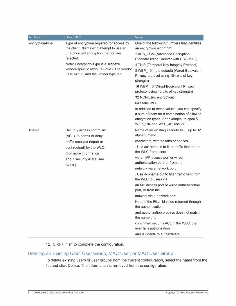
6 Creating MAC Users in the Local User Database Copyright © 2014, Juniper Networks, Inc.
12. Click Finish to complete the configuration.
Deleting an Existing User, User Group, MAC User, or MAC User GroupTo delete existing users or user groups from the current configuration, select the name from the list and click Delete. The information is removed from the configuration.
encryption-type Type of encryption required for access by the client.Clients who attempt to use an unauthorized encryption method are rejected.
Note: Encryption-Type is a Trapeze vendor-specific attribute (VSA). The vendor ID is 14525, and the vendor type is 3.
One of the following numbers that identifies an encryption algorithm:
1 AES_CCM (Advanced Encryption Standard using Counter with CBC-MAC)
4 TKIP (Temporal Key Integrity Protocol)
8 WEP_104 (the default) (Wired-Equivalent Privacy protocol using 104 bits of key strength)
16 WEP_40 (Wired-Equivalent Privacy protocol using 40 bits of key strength)
32 NONE (no encryption)
64 Static WEP
In addition to these values, you can specify a sum of them for a combination of allowed encryption types. For example, to specify WEP_104 and WEP_40, use 24.
filter-id Security access control list
(ACL), to permit or deny
traffic received (input) or
sent (output) by the WLC.
(For more information
about security ACLs, see
ACLs.)
Name of an existing security ACL, up to 32 alphanumeric
characters, with no tabs or spaces.
. Use acl-name.in to filter traffic that enters the WLC from users
via an MP access port or wired authentication port, or from the
network via a network port.
. Use acl-name.out to filter traffic sent from the WLC to users via
an MP access port or wired authentication port, or from the
network via a network port.
Note: If the Filter-Id value returned through the authentication
and authorization process does not match the name of a
committed security ACL in the WLC, the user fails authorization
and is unable to authenticate.
Attribute Description Value
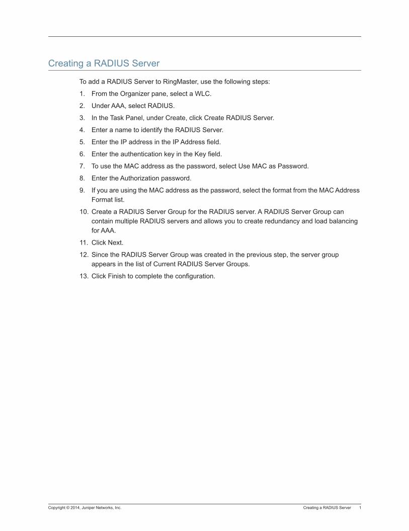
Copyright © 2014, Juniper Networks, Inc. Creating a RADIUS Server 1
Creating a RADIUS Server
To add a RADIUS Server to RingMaster, use the following steps:
1. From the Organizer pane, select a WLC.
2. Under AAA, select RADIUS.
3. In the Task Panel, under Create, click Create RADIUS Server.
4. Enter a name to identify the RADIUS Server.
5. Enter the IP address in the IP Address field.
6. Enter the authentication key in the Key field.
7. To use the MAC address as the password, select Use MAC as Password.
8. Enter the Authorization password.
9. If you are using the MAC address as the password, select the format from the MAC Address Format list.
10. Create a RADIUS Server Group for the RADIUS server. A RADIUS Server Group can contain multiple RADIUS servers and allows you to create redundancy and load balancing for AAA.
11. Click Next.
12. Since the RADIUS Server Group was created in the previous step, the server group appears in the list of Current RADIUS Server Groups.
13. Click Finish to complete the configuration.

2 Creating a RADIUS Server Copyright © 2014, Juniper Networks, Inc.
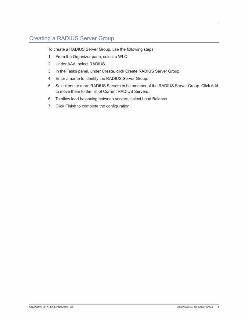
Copyright © 2014, Juniper Networks, Inc. Creating a RADIUS Server Group 1
Creating a RADIUS Server Group
To create a RADIUS Server Group, use the following steps:
1. From the Organizer pane, select a WLC.
2. Under AAA, select RADIUS.
3. In the Tasks panel, under Create, click Create RADIUS Server Group.
4. Enter a name to identify the RADIUS Server Group.
5. Select one or more RADIUS Servers to be member of the RADIUS Server Group. Click Add to move them to the list of Current RADIUS Servers.
6. To allow load balancing between servers, select Load Balance.
7. Click Finish to complete the configuration.

2 Creating a RADIUS Server Group Copyright © 2014, Juniper Networks, Inc.
Copyright © 2014, Juniper Networks, Inc. Configuring RADIUS Accounting Properties 1
Configuring RADIUS Accounting Properties
To enable RADIUS Accounting, use the following steps:
1. From the Organizer pane, select a WLC.
2. Under AAA, select RADIUS.
3. In the Task Panel, under Setup, click System Accounting.
4. Select a RADIUS Server or multiple RADIUS servers from the Available AAA Server Groups, and click Add. The server is moved to the Current AAA Server Groups. As you add servers, you can also change the order that they appear in the list. Use the Up and Down arrows to change the server order in the list.
5. Select Enabled under RADIUS Accounting.
6. Click OK to complete the configuration.

2 Configuring RADIUS Accounting Properties Copyright © 2014, Juniper Networks, Inc.
Copyright © 2014, Juniper Networks, Inc. Creating a RADIUS Dynamic Authorization Client (DAC) 1
Creating a RADIUS Dynamic Authorization Client (DAC)
To create a RADIUS DAC, use the following steps:
1. From the Organizer pane, select a WLC.
2. Under AAA, select RADIUS.
3. In the Tasks panel, under Create, click Create RADIUS DAC.
4. Enter a name to identify the RADIUS DAC.
5. Enter the IP Address of the RADIUS DAC.
6. Enter the authentication key.
7. Click Next.
8. To apply a Wired Access Rule, enable it by selecting Wired Access Rule.
9. Select the SSIDs that the RADIUS DAC can modify connection properties and authorization attributes. Select Any to allow the RADIUS DAC to modify any SSID.
10. Click Add to add the SSID to the list of Associated SSIDs.
11. Click Finish.

2 Creating a RADIUS Dynamic Authorization Client (DAC) Copyright © 2014, Juniper Networks, Inc.
Copyright © 2014, Juniper Networks, Inc. Setting Up RADIUS Defaults 1
Setting Up RADIUS Defaults
You can specify default settings that apply to all RADIUS servers configured on a WLC. You can also specify RADIUS DAC settings that apply to all DACs connecting to the RADIUS DAC server.
To configure default RADIUS settings, use the following steps:
1. From the Organizer pane, select a WLC.
2. Under AAA, select RADIUS.
3. In the Task Panel, under Setup, click RADIUS Defaults.
4. The following default settings can be configured:
Timeout [seconds] — The range is from 1 to 65535 seconds with a default value of 5 seconds.
Retry Count — Specifiy how many times that a RADISU request is retried on the RADIUS server.The range is 1 to 100 with a default value of 3.
Dead Time [minutes] — Specify how long to wait after a RADIUS server times out. The range is 0 to 1440 minutes with a default value of 5 minutes.
Key — Enter the authentication key used to communicate with the RADIUS server.
Use MAC as Password — Use the MAC address of the server as the password.
Authorization Password — Enter the default authorization password for the server.
MAC Address Format — Select the MAC address format for the server. You can select one of the following options:
None
Hyphens
Colons
One Hyphen
Raw
Authentication Protocol — Select the Authentication Protocol for the server. You can select one of the following options:
PAP
CHAP
MSCHAP-V2
RADIUS DAS Port — Configure the port for the Dynamic Authentication Server. The default value is 3799.
5. Click OK to complete the configuration.

2 Setting Up RADIUS Defaults Copyright © 2014, Juniper Networks, Inc.
Copyright © 2014, Juniper Networks, Inc. Configuring Command Audit Properties 1
Configuring Command Audit Properties
To enable RADIUS Accounting, use the following steps:
1. From the Organizer pane, select a WLC.
2. Under AAA, select RADIUS.
3. In the Task Panel, under Setup, click Command Audit.
4. Select the Log level to record the command audit trail. You can select from None, Default, or All.
5. Configure the log file size by selecting the number of kilobytes from the list. Once the maximum is reached, the log begins to overwrite the existing file. The minimum is 200 KB with a maximum of 2000 KB. The default value is 500 KB.
6. Click Next.
7. Select a RADIUS Server Group from the list of Available AAA Server Groups. Click Add to move it to the list of Current AAA Server Groups. You can reorder the servers in the list by using the Up and Down arrows. Once you add the server to the Current AAA Server Group list, Command Accounting is automatically enabled.
8. Click Finish to complete the configuration.

2 Configuring Command Audit Properties Copyright © 2014, Juniper Networks, Inc.
Copyright © 2014, Juniper Networks, Inc. Configuring CDR Accounting Properties 1
Configuring CDR Accounting Properties
To enable CDR Accounting, use the following steps:
1. From the Organizer pane, select a WLC.
2. Under AAA, select RADIUS.
3. In the Task Panel, under Setup, click CDR Accounting.
4. Select a RADIUS Server Group from the list of Available AAA Server Groups. Click Add to move it to the list of Current AAA Server Groups. You can reorder the servers in the list by using the Up and Down arrows. Once you add the server to the Current AAA Server Group list, CDR Accounting is automatically enabled.
5. Click OK to complete the configuration.

2 Configuring CDR Accounting Properties Copyright © 2014, Juniper Networks, Inc.
Copyright © 2014, Juniper Networks, Inc. Configuring RADIUS Ping 1
Configuring RADIUS Ping
RingMaster provides a RADIUS ping utility to enhance troubleshooting capabilities if there are problems communicating with a RADIUS server. The radping command allows a WLC to send an authentication request to a RADIUS server to determine if that server is active or offline. You must authenticate on the RADIUS server using MSCHAPv2 authentication.
To configure RADIUS Ping, use the following steps:
1. From the Organizer panel, select a WLC.
2. Under AAA, select RADIUS.
3. In the Task Panel, under Other, click RADIUS Ping.
4. You can configure the following RADIUS Ping command parameters:
Target — Select a RADIUS Server from the list of servers.
Request Type — Select one of the following Request Types:
Authentication — requires a username and password.
Start Accounting — Begin collecting statistics for user accounts on the server.
Stop Accounting — Stop collecting statistics for user accounts on the server.
Update Accounting — Update the accounting statistics.
Accounting On — Enable accounting statistics collection on the server.
Accounting Off — Enable accounting statistics collection on the server.
5. Enter the Username and Password to authenticate on the RADIUS Server.
6. Click Start.
7. The ping information is displayed in the Status panel.
8. Click Stop to end the session.
Configuring Split Authentication and Authorization
With the implementation of RADIUS Ping, a RADIUS server authenticates a user but authorization attributes are received from the WLC local user database. This is accomplished by including a Vendor-Specific Attribute (VSA) in the RADIUS Accept response. When the WLC receives the RADIUS Accept response, the WLC uses the group name and attempts to match it to authorization attributes of a corresponding user group in the local user database.
To configure this feature, additional attributes must be configured on the RADIUS server. For the user-group name, specify a string consisting of 1-32 characters. Additional values consist of Type - 26, Vendor ID - 14525, Vendor Type - 9 (Trapeze VSA).
Informational Note:
The VSA value remains Trapeze until it is converted to Juniper in the next release of MSS and RingMaster.

2 Configuring RADIUS Ping Copyright © 2014, Juniper Networks, Inc.
Attributes that appear in the RAIDUS Accept response are added to the session attributes. If the Access Accept has a Trapeze group-name VSA, the attributes from the corresponding user group in the local database are applied.
Copyright © 2014, Juniper Networks, Inc. Configuring SmartPass Servers for AAA 1
Configuring SmartPass Servers for AAA
This wizard assists you with configuring SmartPass servers for Authentication, Accounting, Dynamic Authorization, and CDR Accounting. You can also configure a SmartPass server as an External Captive Portal.
To configure a SmartPass Server for AAA, use the following steps:
1. From the Organizer pane, select a WLC.
2. Under AAA, select RADIUS.
3. In the Task Panel, under Setup, click SmartPass.
4. After reading the description of the feature, click Next.
5. From the list of Available SmartPass Servers, select one and click Add to move it to the list of Current SmartPass Servers.
6. Click Next.
7. Configure the SmartPass RADIUS Server Group by selecting an available AAA Server from the list. Click Add to move it to the list of Current RADIUS Servers. If you want to load balance network traffic between the servers, select Load Balance.
8. Select the options from the SmartPass Options list to add to the configuration. You can select from the following options:
Authentication
Accounting
Dynamic Authorization
CDR Accounting
9. Click Next.
10. Select an existing Service Profile, either 802.1X or Web Portal. You can also create a new one by selecting Create New Service Profile. (Link to service profile information)
11. To edit the properties of an existing profile, select it from the list of Service Profiles and click Properties. (Link to Service Profile Type.
12. Click Next.
13. To configure Accounting options, select the SSIDs and the corresponding Access Rules are automatically created.
14. If you select RADIUS DAC, you can configure the RADIUS Server as Self or the SmartPass server.
15. Select Configure as DAC if you want the server to act as a Dynamic Client.
16. Select a SSID from the list of Available SSIDs and click Add to move it to the Associated SSIDs.
17. Click Next.

2 Configuring SmartPass Servers for AAA Copyright © 2014, Juniper Networks, Inc.
18. To configure the CDR Accounting options, select the SmartPass server group from the list of Available AAA Server Groups and click Add to move it to the list of Current AAA Server Groups.
19. Click Finish to complete the configuration.
Copyright © 2014, Juniper Networks, Inc. Creating a LDAP Server 1
Creating a LDAP Server
To create a LDAP Server, use the following steps:
1. In the Organizer panel, select a WLC.
2. Under AAA, click LDAP Server.
3. From the Tasks panel, click Create LDAP Server.
4. Enter a unique name for the LDAP Server.
5. Enter the IP Address of the server.
6. Enter the Fully Qualified Domain Name (FQDN) of the LDAP server.
7. Click Next.
8. An LDAP Server Group is automatically created with the name of the LDAP Server.
9. Click Next.
10. The LDAP Server Group appears in the list of Current LDAP Server Groups. If you want to remove it from the server group, select it and click Remove.
11. Click Finish to complete the configuration.
Changing LDAP Server PropertiesTo change any of the LDAP Server properties, select it from the list of servers and click Properties. Change the desired options, and click OK to complete the configuration. You can change the following options:
IP Address
Timeout [seconds] - Sets the timeout for communication with the LDAP server. You can set the time in seconds with a range of 1 to 65535 seconds. The default value is 5 seconds.
Authentication Port - The default port is 389.
Dead Time [minutes] - The length of time to wait before recontacting a LDAP server. The range is 0 to 1440 minutes with a default value of 5 minutes.
Bind Mode - Select from NONE, SIMPLE-AUTH, SASL-MD5.
MAC Address Format - Select from None, Hyphens, Colons, One Hyphen, or Raw.
Base DN -
Prefix DN -
Deleting a LDAP Server To delete any of the LDAP Servers, select it from the list of servers and click Delete. Click Finish to confirm that you want to delete the server.

2 Creating a LDAP Server Copyright © 2014, Juniper Networks, Inc.
Copyright © 2014, Juniper Networks, Inc. Creating a LDAP Server Group 1
Creating a LDAP Server Group
To create a LDAP Server Group, use the following steps:
1. In the Organizer panel, select a WLC.
2. Under AAA, click Create LDAP Server Group.
3. Enter a unique name for the LDAP Server Group.
4. Select one or more LDAP Servers to add to the group.
5. Click Add to move the servers to the Current LDAP Servers list. You can change the order of the servers by using the Up and Down arrows.
6. Click Finish to complete the configuration.
Changing LDAP Server Group PropertiesTo change the LDAP Server Group properties, select it from the list of LDAP Server Groups, and click Properties. You can change the following properties:
Load Balancing
Adding or Removing LDAP Servers from the LDAP Server Group.
Deleting a LDAP Server GroupTo delete any of the LDAP Server Groups, select it from the list of servers and click Delete. Click Finish to confirm that you want to delete the server group.

2 Creating a LDAP Server Group Copyright © 2014, Juniper Networks, Inc.
Copyright © 2014, Juniper Networks, Inc. Configuring LDAP Default Settings 1
Configuring LDAP Default Settings
To create a LDAP Server Group, use the following steps:
1. In the Organizer panel, select a WLC.
2. Under AAA, select LDAP.
3. In the Tasks panel, under Setup, click LDAP Defaults.
4. You can change the following default settings
Timeout [seconds] - Sets the timeout for communication with the LDAP server. You can set the time in seconds with a range of 1 to 65535 seconds. The default value is 5 seconds.
Authentication Port - The default port is 389.
Dead Time [minutes] - The length of time to wait before recontacting a LDAP server. The range is 0 to 1440 minutes with a default value of 5 minutes.
Bind Mode - Select from NONE, SIMPLE-AUTH, SASL-MD5.
MAC Address Format - Select from Hyphens, Colons, One Hyphen, or Raw.
Fully Qualified Domain Name (FQDN) - the domain name for the LDAP Server.
Base DN -
Prefix DN -
5. Click OK to complete the configuration.

2 Configuring LDAP Default Settings Copyright © 2014, Juniper Networks, Inc.
Copyright © 2014, Juniper Networks, Inc. Configuring 802.1X Global Parameters 1
Configuring 802.1X Global Parameters
802.1X Access Rules include information about the Extensible Authentication Protocol (EAP) type to use for AAA communication between the client and the AAA server. The EAP type can be one of the following:
EAP-MD5 Offload — EAP with Message-Digest (algorithm)5 (MD5). Select this protocol for wired clients.
Uses challenge-response to compare hashes.
Dynamic Authorization Server Port — the UDP where the DAS listens for Disconnect and CoA requests sent by the DAC.
To configure 802.1X global parameters, use the following steps:
1. In the Organizer panel, select a WLC.
2. Under AAA, click 802.1X.
3. In the 802.1X section, you can configure the following parameters:
802.1X
System Authentication Control — To enable 802.1X authentication for all wired authentication ports on the WLC, select System Authentication Control. To disable 802.1X authentication for all wired authentication ports, clear System Authentication Control. By default, 802.1X authentication is enabled.
Retransmit Timeout [seconds] — To specify the number of seconds before retransmitting an Extensible Authentication Protocol over LAN (EAPoL) packet, specify the timeout value (1 to 65,535 seconds) in the Retransmit Timeout field. The default is 5 seconds.
Authentication Server Timeout [seconds] — To specify the number of seconds before timing out a request to an authentication server, specify the timeout value (1 to 65,535 seconds) in the Authentication Server Timeout field. The default is 30 seconds.
Key Transmit — To enable encryption key information to be sent to the client after authentication in EAPoL-Key PDUs, select Key Transmit. The WLC sends EAPoL key messages after successfully authenticating the client and receiving authorization attributes for the client. If the client is using dynamic WEP, the EAPoL key messages are sent immediately after authorization. To disable this option, clear Key Transmit. By default, this option is enabled.
Reauthentication Attempts — To specify the number of reauthentication requests before a client becomes unauthorized, specify the value (1 to 10) in the Reauthentication Attempts field. The default is 2 attempts.
Bonded Period [seconds] — To specify the number of seconds MSS retains session information for Bonded Auth™(bonded authentication), specify the value, from 1 to 300 seconds, in the Bonded Period field. The default is 0 seconds.
2 Configuring 802.1X Global Parameters Copyright © 2014, Juniper Networks, Inc.
Quiet Period Timeout [seconds] — To specify the number of seconds before attempting reauthentication, specify the timeout value (0 to 65,535 seconds) in the Quiet Period Timeout field. The default is 60 seconds.
Supplicant Timeout [seconds] — To specify the number of seconds before timing out an authentication session with an 802.1X client (supplicant), specify the timeout value (1 to 65,535 seconds) in the Supplicant Timeout field. The default is 30 seconds.
Maximum Requests — To set the maximum number of times an EAP request is transmitted to the client before timing out the authentication session, specify the value (0 to 10) in the Maximum Requests field. The default is 2 attempts.
Reauthentication — To enable reauthentication of 802.1X clients, select Reauthentication. To disable reauthentication, clear Reauthentication. By default, reauthentication is enabled.
Reauthentication Period [seconds] — To specify the number of seconds before reauthentication is attempted, specify the timeout value, from 60 to 1,641,600 seconds (19 days), in the Reauthentication Period field. The default is 3600 seconds (one hour). MSS re-authenticates dynamic WEP clients based on a re-authentication timer. MSS also re-authenticates WPA clients if they use WEP-40 or WEP-104 cipher. For each dynamic WEP client or WPA client using a WEP cipher, the reauthentication timer is set to the lesser of the global setting or the value returned by the AAA server with the rest of the authorization attributes for that client.
Handshake Timeout [msecs] — Set the handshake timeout period. You can enter a value in mseconds from 20 to 5000. The default value is 2000 mseconds.
WEP Key Rolling
WEP Key Rolling — To enable WEP key rolling (rotation) of the broadcast and multicast WEP keys, select WEP Key Rolling.
WEP Key Rolling Period [seconds] — To specify the time to wait before rotating the WEP key, specify the value, from 30 to 1,641,600 seconds, (19 days) in the WEP Key Rolling Period field. The default is 1800 seconds (30 minutes).
Informational Note:
To support SSIDs that have both 802.1X and static WEP clients, MSS sends a maximum of two ID requests, even if this parameter is set to a higher value. Setting the parameter to a higher value does affect all other types of EAP messages.
Informational Note:
If the number of reauthentications for a wired authentication client is greater than the maximum number of reauthentications allowed, MSS sends an EAP failure packet to the client and removes the client from the network. However, MSS does not remove a wireless client from the network under these circumstances.
Copyright © 2014, Juniper Networks, Inc. Configuring 802.1X Global Parameters 3
TKIP/CCMP Key Rolling
To maintain secure wireless access to the network, keys used to encrypt packets should be difficult to guess or hack by a third party.
Adding the option to enable or disable unicast periodic rekeying with a configurable interval value. When the timer expires, the client unicast key (PTK) is changed when a 4-way handshake is initiated.
Adding the option to enable multicast periodic rekeying with a configurable interval value. When the timer expires, all VLAN keys (GTK) is changed by initiating a 4-way or 2-way handshake.
Unicast Key Rolling — select to enable Unicast Key Rolling.
Unicast Key Rolling Period [seconds] — Configure a value from 30 to 86400 seconds. The default value is 300 seconds.
Multicast Key Rolling — select to enable Multicast Key Rolling.
Multicast Key Rolling [seconds] — Configure a value from 30 to 86400 seconds. The default value is 300 seconds.

4 Configuring 802.1X Global Parameters Copyright © 2014, Juniper Networks, Inc.
Copyright © 2014, Juniper Networks, Inc. Creating AAA Profiles 1
Creating AAA Profiles
To configure AAA Profiles, use the following steps:
1. In the Organizer panel, select a WLC.
2. Under AAA, click AAA Profiles.
3. In the Tasks panel, under Create, click Create AAA Profile.
4. Enter a unique name to identify the profile.
5. Click Next.
6. You can add, modify, or create Access Rules associated with this profile.
Creating an Access Rule
7. Click Create. You can create one of the following types of Access Rules:
802.1X Authentication Rule (x-ref to configuring this type of rule)
MAC Authentication Rule
Web Authentication Rule
8. Click Finish to complete the configuration.
If you want to modify the Access Rule, select the Rule and then click Properties. Edit any of the available parameters and click OK.
You can reorder the rules in the list using the Up and Down arrows.

2 Creating AAA Profiles Copyright © 2014, Juniper Networks, Inc.
Copyright © 2014, Juniper Networks, Inc. Creating AAA Profile Access 1
Creating AAA Profile Access
To configure AAA Profile Access, use the following steps:
1. In the Organizer panel, select a WLC.
2. Under AAA, click AAA Profiles.
3. In the Tasks panel, under Create, click Create AAA Profile Access.
4. From the SSID list, select a SSID to apply the access rule. If the rule applies to Wired Auth users, select Wired Auth.
5. Select an AAA Profile from the list.
6. Click Next.
Optional: Accounting Servers
7. To enable accounting for the profile, select Enabled.
8. From the Record Type list, select from the following options:
Start-Stop
Start-Only
9. From the list of Available AAA Server Groups, select one from the list and click Add to move it to the list of Current AAA Server Groups. You can reorder the server groups in the list by using the Up and Down arrows.
10. Click Finish to complete the configuration.

2 Creating AAA Profile Access Copyright © 2014, Juniper Networks, Inc.
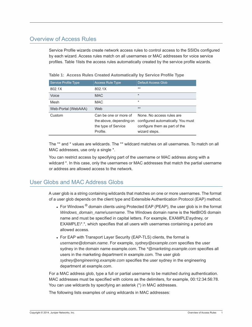
Copyright © 2014, Juniper Networks, Inc. Overview of Access Rules 1
Overview of Access Rules
Service Profile wizards create network access rules to control access to the SSIDs configured by each wizard. Access rules match on all usernames or MAC addresses for voice service profiles. Table 1lists the access rules automatically created by the service profile wizards.
The ** and * values are wildcards. The ** wildcard matches on all usernames. To match on all MAC addresses, use only a single *.
You can restrict access by specifying part of the username or MAC address along with a wildcard *. In this case, only the usernames or MAC addresses that match the partial username or address are allowed access to the network.
User Globs and MAC Address Globs
A user glob is a string containing wildcards that matches on one or more usernames. The format of a user glob depends on the client type and Extensible Authentication Protocol (EAP) method.
For Windows ® domain clients using Protected EAP (PEAP), the user glob is in the format Windows_domain_name\username. The Windows domain name is the NetBIOS domain name and must be specified in capital letters. For example, EXAMPLE\sydney, or EXAMPLE\*.*, which specifies that all users with usernames containing a period are allowed access.
For EAP with Transport Layer Security (EAP-TLS) clients, the format is [email protected]. For example, [email protected] specifies the user sydney in the domain name example.com. The *@marketing.example.com specifies all users in the marketing department in example.com. The user glob [email protected] specifies the user sydney in the engineering department at example.com.
For a MAC address glob, type a full or partial username to be matched during authentication. MAC addresses must be specified with colons as the delimiters, for example, 00:12:34:56:78. You can use wildcards by specifying an asterisk (*) in MAC addresses.
The following lists examples of using wildcards in MAC addresses:
Table 1: Access Rules Created Automatically by Service Profile Type
Service Profile Type Access Rule Type Default Access Glob
802.1X 802.1X **
Voice MAC *
Mesh MAC *
Web-Portal (WebAAA) Web **
Custom Can be one or more of the above, depending on the type of Service Profile.
None. No access rules are configured automatically. You must configure them as part of the wizard steps.

2 User Globs and MAC Address Globs Copyright © 2014, Juniper Networks, Inc.
* (all MAC addresses)
00:*
00:01:*
00:01:02*
00:01:02:03:*
00:01:02:03:04:*
00:01:02:03:04::0*
Copyright © 2014, Juniper Networks, Inc. Creating an 802.1X Authentication Rule 1
Creating an 802.1X Authentication Rule
To configure an 802.1X Access Rule, use the following steps.
1. From the Organizer panel, select a WLC.
2. Select AAA, and the 802.1X Access Rules.
3. From the Tasks panel, under Create, select 802.1X Access Rule.
4. Select a SSID from the SSID list.
5. If the rule applies to a Wired Auth user, select Wired.
6. In the Matching User Glob field, enter specific usernames or “**” to match all usernames.
7. Click Next.
EAP Type8. Select the EAP Type from the list. You can select from the following options:
External Authentication Server — No protocol is used by the WLC. Mobility System Software (MSS) sends the EAP processing to a RADIUS server. If you select PEAP, the EAP Sub-Protocol is MS-CHAPV2. For other protocols, there is no the EAP Sub-Protocol to select.
EAP-MD5 Offload — Extensible Authentication Protocol (EAP) with message-digest algorithm 5. Select this protocol for wired authentication clients.
− Uses challenge-response to compare hashes.
− Provides no encryption or integrity checking for the connection.
PEAP Offload — Protected EAP with Microsoft Challenge Handshake Authentication Protocol Version 2 (MS-CHAP-V2). Select this protocol for wireless clients.
− Uses TLS for encryption and data integrity checking.
− Provides MS-CHAP-V2 mutual authentication.
− Only the server side of the connection needs a certificate.
Local EAP-TLS — EAP with TLS.
− Provides mutual authentication, integrity-protected negotiation, and key exchange.
− Requires X.509 public key certificates on both sides of the connection.
− Provides encryption and integrity checking for the connection.
− Cannot be used with RADIUS server authentication (requires user information to be in the local database of the WLC).
9. If you selected PEAP as the EAP type, MS-CHAPV2 is selected by default as the EAP Sub-Protocol.
10. Click Next.
Authentication Servers
11. To enable authentication, select Enabled.
2 Creating an 802.1X Authentication Rule Copyright © 2014, Juniper Networks, Inc.
12. Select a server group from the list of Available AAA Server Groups, and click Add to move it to the list of Current AAA Server Groups. You can reorder the list by using the Up and Down arrows.
If you select Local, you are adding the local database on the WLC.
13. Click Next.
Optional: Accounting Servers
14. To enable accounting for the profile, select Enabled.
15. From the Record Type list, select from the following options:
Start-Stop
Stop-Only
16. From the list of Available AAA Server Groups, select one from the list and click Add to move it to the list of Current AAA Server Groups. You can reorder the server groups in the list by using the Up and Down arrows.
17. Click OK to complete the configuration.
Copyright © 2014, Juniper Networks, Inc. Creating a MAC Access Rule 1
Creating a MAC Access Rule
To create a MAC Access Rule, use the following steps:
1. From the Organizer panel, select a WLC.
2. Under AAA, select MAC Access Rules.
3. In the Tasks panel, under Create, click MAC Network Access.
4. Select a SSID from the SSID list.
5. If the rule applies to a Wired Auth user, select Wired.
6. In the Matching MAC Address Glob field, you can either specify a user MAC address or a MAC Address Glob up to 5 bytes long ending with “*:” to match specific MAC addresses or “*” to match all MAC addresses.
7. Click Next.
Authentication Servers
8. To enable authentication, select Enabled.
9. To use the MAC Address Prefix, select MAC Prefix.
10. Select a server group from the list of Available AAA Server Groups, and click Add to move it to the list of Current AAA Server Groups. You can reorder the list by using the Up and Down arrows.
If you select Local, you are adding the local database on the WLC. MAC Authentication allows you to select from RADIUS or LDAP servers.
Optional: Accounting Servers
11. To enable accounting for the profile, select Enabled.
12. From the Record Type list, select from the following options:
Start-Stop
Stop-Only
13. From the list of Available AAA Server Groups, select one from the list and click Add to move it to the list of Current AAA Server Groups. You can reorder the server groups in the list by using the Up and Down arrows.
14. Click Finish to complete the configuration.

2 Creating a MAC Access Rule Copyright © 2014, Juniper Networks, Inc.
Copyright © 2014, Juniper Networks, Inc. Creating a Web Authentication Rule 1
Creating a Web Authentication Rule
To configure a Web Access Rule, use the following steps.
1. From the Organizer panel, select a WLC.
2. Select AAA, and theWeb Access Rules.
3. From the Tasks panel, under Create, select Web Access Rule.
4. Select a SSID from the SSID list.
5. If the rule applies to a Wired Auth user, select Wired.
6. In the Matching User Glob field, enter specific usernames or “**” to match all usernames.
7. Click Next.
8. Select a server group from the list of Available AAA Server Groups, and click Add to move it to the list of Current AAA Server Groups. You can reorder the list by using the Up and Down arrows.
If you select Local, you are adding the local database on the WLC. MAC Authentication allows you to select from RADIUS or LDAP servers.
Optional: Accounting Servers
9. To enable accounting for the profile, select Enabled.
10. From the Record Type list, select from the following options:
Start-Stop
Stop-Only
11. From the list of Available AAA Server Groups, select one from the list and click Add to move it to the list of Current AAA Server Groups. You can reorder the server groups in the list by using the Up and Down arrows.
12. Click Finish to complete the configuration.

2 Creating a Web Authentication Rule Copyright © 2014, Juniper Networks, Inc.
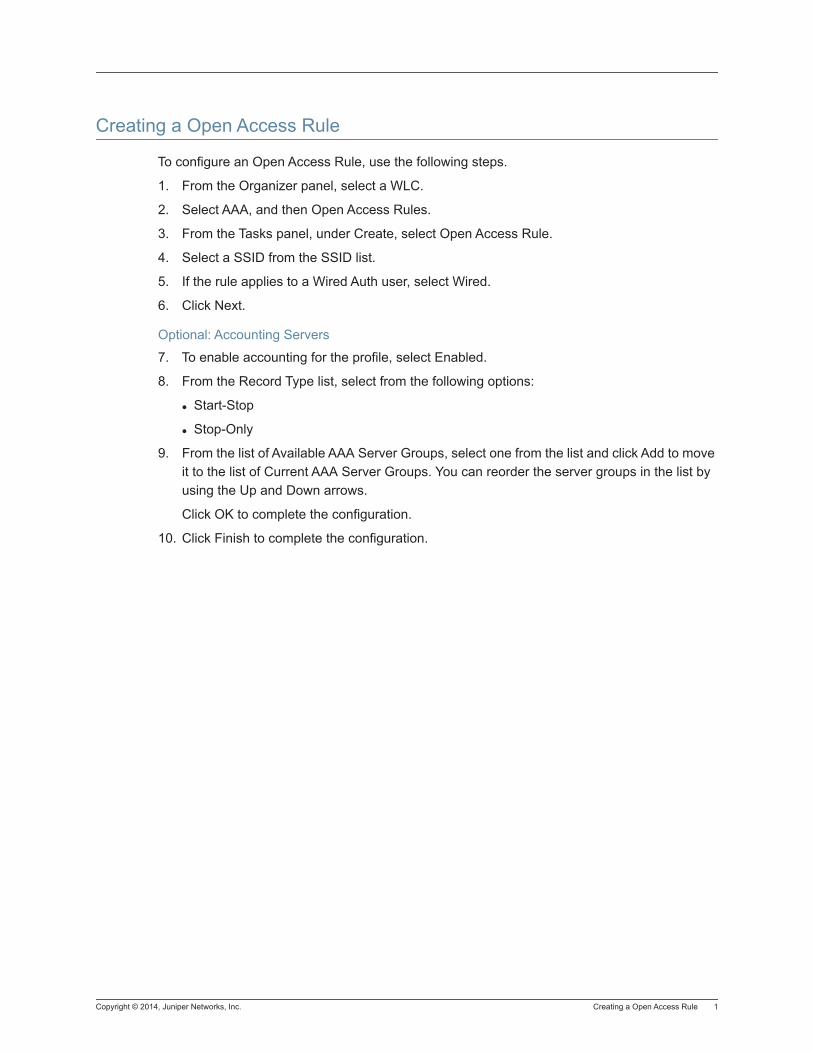
Copyright © 2014, Juniper Networks, Inc. Creating a Open Access Rule 1
Creating a Open Access Rule
To configure an Open Access Rule, use the following steps.
1. From the Organizer panel, select a WLC.
2. Select AAA, and then Open Access Rules.
3. From the Tasks panel, under Create, select Open Access Rule.
4. Select a SSID from the SSID list.
5. If the rule applies to a Wired Auth user, select Wired.
6. Click Next.
Optional: Accounting Servers
7. To enable accounting for the profile, select Enabled.
8. From the Record Type list, select from the following options:
Start-Stop
Stop-Only
9. From the list of Available AAA Server Groups, select one from the list and click Add to move it to the list of Current AAA Server Groups. You can reorder the server groups in the list by using the Up and Down arrows.
Click OK to complete the configuration.
10. Click Finish to complete the configuration.

2 Creating a Open Access Rule Copyright © 2014, Juniper Networks, Inc.
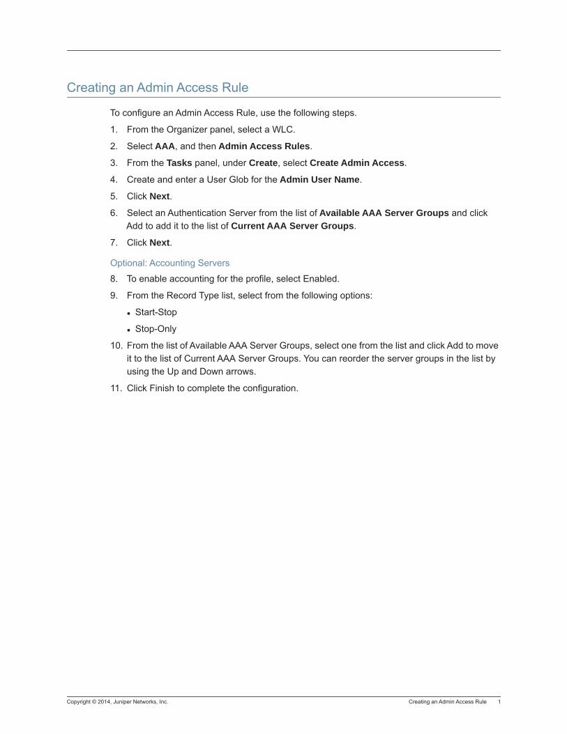
Copyright © 2014, Juniper Networks, Inc. Creating an Admin Access Rule 1
Creating an Admin Access Rule
To configure an Admin Access Rule, use the following steps.
1. From the Organizer panel, select a WLC.
2. Select AAA, and then Admin Access Rules.
3. From the Tasks panel, under Create, select Create Admin Access.
4. Create and enter a User Glob for the Admin User Name.
5. Click Next.
6. Select an Authentication Server from the list of Available AAA Server Groups and click Add to add it to the list of Current AAA Server Groups.
7. Click Next.
Optional: Accounting Servers
8. To enable accounting for the profile, select Enabled.
9. From the Record Type list, select from the following options:
Start-Stop
Stop-Only
10. From the list of Available AAA Server Groups, select one from the list and click Add to move it to the list of Current AAA Server Groups. You can reorder the server groups in the list by using the Up and Down arrows.
11. Click Finish to complete the configuration.

2 Creating an Admin Access Rule Copyright © 2014, Juniper Networks, Inc.
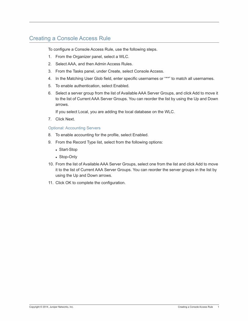
Copyright © 2014, Juniper Networks, Inc. Creating a Console Access Rule 1
Creating a Console Access Rule
To configure a Console Access Rule, use the following steps.
1. From the Organizer panel, select a WLC.
2. Select AAA, and then Admin Access Rules.
3. From the Tasks panel, under Create, select Console Access.
4. In the Matching User Glob field, enter specific usernames or “**” to match all usernames.
5. To enable authentication, select Enabled.
6. Select a server group from the list of Available AAA Server Groups, and click Add to move it to the list of Current AAA Server Groups. You can reorder the list by using the Up and Down arrows.
If you select Local, you are adding the local database on the WLC.
7. Click Next.
Optional: Accounting Servers
8. To enable accounting for the profile, select Enabled.
9. From the Record Type list, select from the following options:
Start-Stop
Stop-Only
10. From the list of Available AAA Server Groups, select one from the list and click Add to move it to the list of Current AAA Server Groups. You can reorder the server groups in the list by using the Up and Down arrows.
11. Click OK to complete the configuration.

2 Creating a Console Access Rule Copyright © 2014, Juniper Networks, Inc.
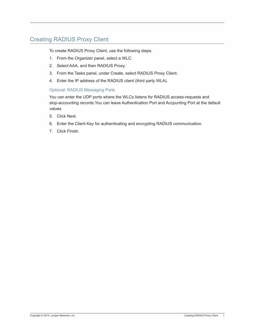
Copyright © 2014, Juniper Networks, Inc. Creating RADIUS Proxy Client 1
Creating RADIUS Proxy Client
To create RADIUS Proxy Client, use the following steps.
1. From the Organizer panel, select a WLC.
2. Select AAA, and then RADIUS Proxy.
3. From the Tasks panel, under Create, select RADIUS Proxy Client.
4. Enter the IP address of the RADIUS client (third party WLA).
Optional: RADIUS Messaging Ports
You can enter the UDP ports where the WLCs listens for RADIUS access-requests and stop-accounting records.You can leave Authentication Port and Accpunting Port at the default values
5. Click Next.
6. Enter the Client Key for authenticating and encrypting RADIUS communication.
7. Click Finish.

2 Creating RADIUS Proxy Client Copyright © 2014, Juniper Networks, Inc.
Copyright © 2014, Juniper Networks, Inc. Creating Proxy Access 1
Creating Proxy Access
To configure Proxy Access, use the following steps.
1. From the Organizer panel, select a WLC.
2. Select AAA, and then RADIUS Proxy.
3. From the Tasks panel, under Create, select Proxy Access.
4. In the Matching User Glob field, enter specific usernames or “**” to match all usernames.
5. To enable authentication, select Enabled.
6. Select a server group from the list of Available AAA Server Groups, and click Add to move it to the list of Current AAA Server Groups. You can reorder the list by using the Up and Down arrows.
If you select Local, you are adding the local database on the WLC.
7. Click Next.
Optional: RADIUS Server Group
8. From the list of Available AAA Server Groups, select one from the list and click Add to move it to the list of Current AAA Server Groups. You can reorder the server groups in the list by using the Up and Down arrows.
If you select Local, you are adding the local database on the WLC.
9. Click Finish to complete the configuration.

2 Creating Proxy Access Copyright © 2014, Juniper Networks, Inc.
Copyright © 2014, Juniper Networks, Inc. Creating 802.1Q Mappings 1
Creating 802.1Q Mappings
To create 802.1Q Mappings, use the following steps.
1. From the Organizer panel, select a WLC.
2. Select AAA, and then RADUIS Proxy.
3. From the Tasks panel, under Create, select 802.1Q Mappings.
4. Select a Port.
5. Enter the SSID.
6. Create a unique tag for the mapping.
7. Click OK.

2 Creating 802.1Q Mappings Copyright © 2014, Juniper Networks, Inc.
Copyright © 2014, Juniper Networks, Inc. Creating a Location Policy Rule 1
Creating a Location Policy Rule
To configure a Location Policy Rule, use the following steps.
1. From the Organizer panel, select a WLC.
2. Select AAA, and then Location Policy.
3. From the Tasks panel, under Create, select Create Location Policy Rule.
4. Configure the Location Rule Match Option. You can select from the following options:
SSID
User Glob
VLAN
Time of Day
Port List
DAP List
5. For each of the listed options, select the values to use for the Location Policy. Click Next.
Optional: Port Criteria
6. Select a physical port to apply the location policy. Click Next.
Optional: Distributed WLAs Criteria
7. Select from a distributed WLA from the list of Available Distributed WLAs, and click Add to put it in the Current Distributed WLAs list.
8. Click Next.
Location Rule Action
9. Configure the Location Rule to allow or deny access to the network. If access is allowed you can override authorization attributes by specifying new values. You can configure the following parameters:
Action
In ACL
Out ACL
VLAN Name
Time of Day Action
URL
QoS Profile
Termination Action
10. Click Finish to complete the configuration.

2 Creating a Location Policy Rule Copyright © 2014, Juniper Networks, Inc.
Copyright © 2014, Juniper Networks, Inc. Creating a Mobility Profile 1
Creating a Mobility Profile
To configure a Location Policy Rule, use the following steps.
1. From the Organizer panel, select a WLC.
2. Select AAA, and then Mobility Profiles.
3. From the Tasks panel, under Create, select Create Mobility Profile.
4. Create a unique name for the Mobility Profile.
Optional: Mobility Profile Port Selection
5. Select a physical port from the list of Available Physical Ports, and click Add to put it in the Current Physical Ports list.
6. Click Next.
Optional: Distributed WLAs Criteria
7. Select from a distributed WLA from the list of Available Distributed WLAs, and click Add to put it in the Current Distributed WLAs list.
8. Click Finish.

2 Creating a Mobility Profile Copyright © 2014, Juniper Networks, Inc.
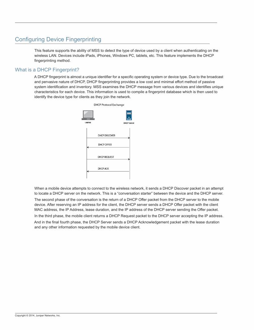
Copyright © 2014, Juniper Networks, Inc.
Configuring Device Fingerprinting
This feature supports the ability of MSS to detect the type of device used by a client when authenticating on the wireless LAN. Devices include iPads, iPhones, Windows PC, tablets, etc. This feature implements the DHCP fingerprinting method.
What is a DHCP Fingerprint?A DHCP fingerprint is almost a unique identifier for a specific operating system or device type. Due to the broadcast and pervasive nature of DHCP, DHCP fingerprinting provides a low cost and minimal effort method of passive system identification and inventory. MSS examines the DHCP message from various devices and identifies unique characteristics for each device. This information is used to compile a fingerprint database which is then used to identify the device type for clients as they join the network.
When a mobile device attempts to connect to the wireless network, it sends a DHCP Discover packet in an attempt to locate a DHCP server on the network. This is a “conversation starter” between the device and the DHCP server.
The second phase of the conversation is the return of a DHCP Offer packet from the DHCP server to the mobile device. After reserving an IP address for the client, the DHCP server sends a DHCP Offer packet with the client MAC address, the IP Address, lease duration, and the IP address of the DHCP server sending the Offer packet.
In the third phase, the mobile client returns a DHCP Request packet to the DHCP server accepting the IP address.
And in the final fourth phase, the DHCP Server sends a DHCP Acknowledgement packet with the lease duration and any other information requested by the mobile device client.
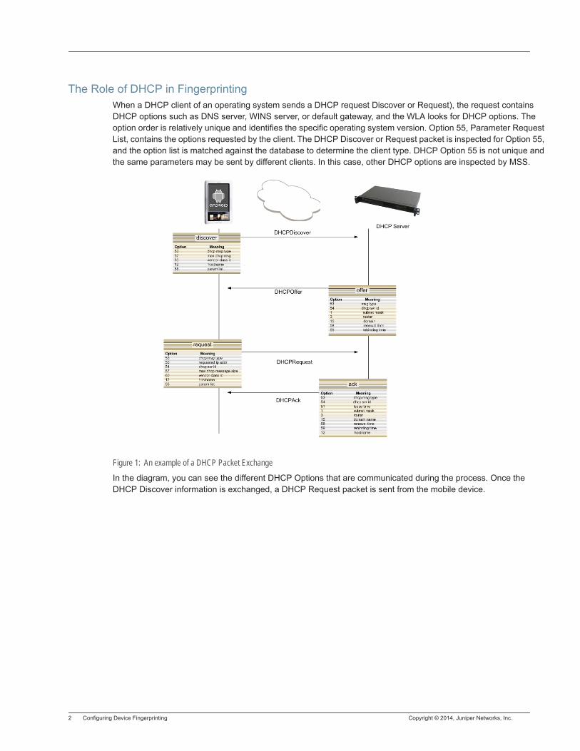
2 Configuring Device Fingerprinting Copyright © 2014, Juniper Networks, Inc.
The Role of DHCP in FingerprintingWhen a DHCP client of an operating system sends a DHCP request Discover or Request), the request contains DHCP options such as DNS server, WINS server, or default gateway, and the WLA looks for DHCP options. The option order is relatively unique and identifies the specific operating system version. Option 55, Parameter Request List, contains the options requested by the client. The DHCP Discover or Request packet is inspected for Option 55, and the option list is matched against the database to determine the client type. DHCP Option 55 is not unique and the same parameters may be sent by different clients. In this case, other DHCP options are inspected by MSS.
Figure 1: An example of a DHCP Packet Exchange
In the diagram, you can see the different DHCP Options that are communicated during the process. Once the DHCP Discover information is exchanged, a DHCP Request packet is sent from the mobile device.
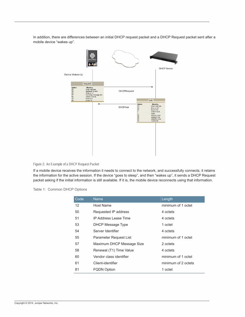
Copyright © 2014, Juniper Networks, Inc.
In addition, there are differences between an initial DHCP request packet and a DHCP Request packet sent after a mobile device “wakes up”.
Figure 2: An Example of a DHCP Request Packet
If a mobile device receives the information it needs to connect to the network, and successfully connects, it retains the information for the active session. If the device “goes to sleep”, and then “wakes up”, it sends a DHCP Request packet asking if the initial information is still available. If it is, the mobile device reconnects using that information.
Table 1: Common DHCP Options
Code Name Length
12 Host Name minimum of 1 octet
50 Requested IP address 4 octets
51 IP Address Lease Time 4 octets
53 DHCP Message Type 1 octet
54 Server Identifier 4 octets
55 Parameter Request List minimum of 1 octet
57 Maximum DHCP Message Size 2 octets
58 Renewal (T1) Time Value 4 octets
60 Vendor class identifier minimum of 1 octet
61 Client-identifier minimum of 2 octets
81 FQDN Option 1 octet
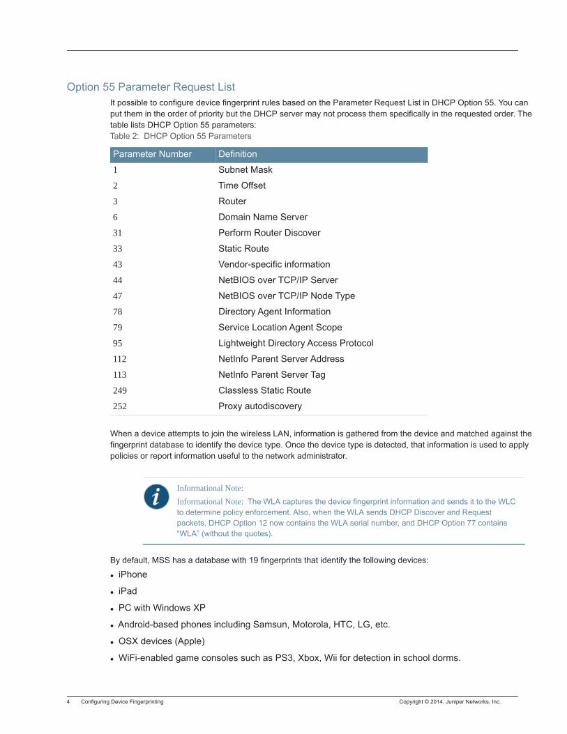
4 Configuring Device Fingerprinting Copyright © 2014, Juniper Networks, Inc.
Option 55 Parameter Request ListIt possible to configure device fingerprint rules based on the Parameter Request List in DHCP Option 55. You can put them in the order of priority but the DHCP server may not process them specifically in the requested order. The table lists DHCP Option 55 parameters:
When a device attempts to join the wireless LAN, information is gathered from the device and matched against the fingerprint database to identify the device type. Once the device type is detected, that information is used to apply policies or report information useful to the network administrator.
By default, MSS has a database with 19 fingerprints that identify the following devices:
iPhone
iPad
PC with Windows XP
Android-based phones including Samsun, Motorola, HTC, LG, etc.
OSX devices (Apple)
WiFi-enabled game consoles such as PS3, Xbox, Wii for detection in school dorms.
Table 2: DHCP Option 55 Parameters
Parameter Number Definition
1 Subnet Mask
2 Time Offset
3 Router
6 Domain Name Server
31 Perform Router Discover
33 Static Route
43 Vendor-specific information
44 NetBIOS over TCP/IP Server
47 NetBIOS over TCP/IP Node Type
78 Directory Agent Information
79 Service Location Agent Scope
95 Lightweight Directory Access Protocol
112 NetInfo Parent Server Address
113 NetInfo Parent Server Tag
249 Classless Static Route
252 Proxy autodiscovery
Informational Note: Informational Note: The WLA captures the device fingerprint information and sends it to the WLC to determine policy enforcement. Also, when the WLA sends DHCP Discover and Request packets, DHCP Option 12 now contains the WLA serial number, and DHCP Option 77 contains “WLA” (without the quotes).
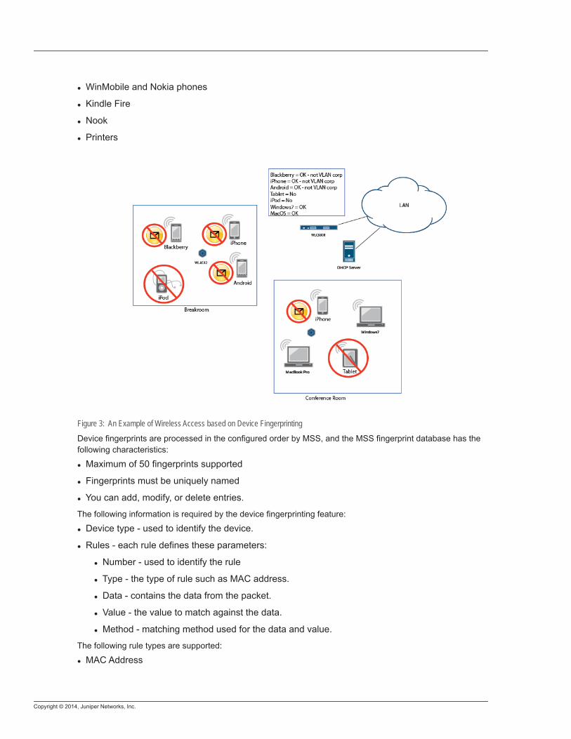
Copyright © 2014, Juniper Networks, Inc.
WinMobile and Nokia phones
Kindle Fire
Nook
Printers
Figure 3: An Example of Wireless Access based on Device Fingerprinting
Device fingerprints are processed in the configured order by MSS, and the MSS fingerprint database has the following characteristics:
Maximum of 50 fingerprints supported
Fingerprints must be uniquely named
You can add, modify, or delete entries.
The following information is required by the device fingerprinting feature:
Device type - used to identify the device.
Rules - each rule defines these parameters:
Number - used to identify the rule
Type - the type of rule such as MAC address.
Data - contains the data from the packet.
Value - the value to match against the data.
Method - matching method used for the data and value.
The following rule types are supported:
MAC Address
6 Configuring Device Fingerprinting Copyright © 2014, Juniper Networks, Inc.
Data - the device MAC address
Value - MAC “glob” using the existing MAC rules in MSS
Method - MAC “glob” comparison
DHCP Flags
Data - DHCP flags field
Value - 2 byte mask -
Method - Bitwise AND
DHCP Option
Data - Byte data from the specified DHCP option.
− Option number is an integer.
− Option content is a string of consisting of either a string, hex, or an order sensitive list of DHCP option numbers.
− Method - “eq” or “neq” based on the current MSS implementation. It matches if both are “eq”. “Contains” and “Not Contains” are also supported/
DHCP Options List
Data - List of DHCP Options from the DHCP packet
Value - list of desired DHCP options in a format consistent with Options content list.
Method - one of “eq” or “neq” or “contains” or “not contain”
Combination of rules - rules are not used directly in the detection process but combined to gether to create a rule expression. This consists of a logical expression specified as a string and can contain the following tokens:
rule number - one of the defined rules for this fingerprint
“and” and “or” used for logical tests
“(“and”)” used for grouping
white space - used for separation of the tokens.
Interactions between the User Policy and the Device PolicyWho wins? All attributes from a device policy and user policy are applied to a session except when there are conflicts. When there is a conflict, device policies take precedence over user policies by default. You can change the precedence in the CLI.
Other Functionalities Supported by Device FingerprintingDevice detection works in parallel with AAA, so all AAA methods are compatible. It is also supported in a cluster (high availability) environment.
Use Cases
Controlling Network Access on a Corporate WLAN for a Personal iPad — A user joins the network through an 802.1X authentication process while using his personal iPad. Authentication is performed through a RADIUS server, credentials accepted, and an attribute is returned to the user allowing him to join VLAN1. The WLC detects that the user’s device is an iPad and applies a new ACL that only allows the user access to an e-mail server, and public internet access.
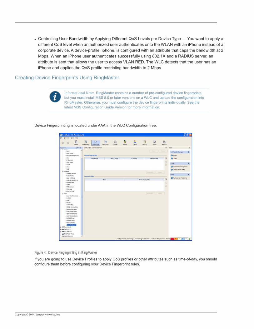
Copyright © 2014, Juniper Networks, Inc.
Controlling User Bandwidth by Applying Different QoS Levels per Device Type — You want to apply a different CoS level when an authorized user authenticates onto the WLAN with an iPhone instead of a corporate device. A device-profile, iphone, is configured with an attribute that caps the bandwidth at 2 Mbps. When an iPhone user authenticates successfully using 802.1X and a RADIUS server, an attribute is sent that allows the user to access VLAN RED. The WLC detects that the user has an iPhone and applies the QoS profile restricting bandwidth to 2 Mbps.
Creating Device Fingerprints Using RingMaster
Device Fingerprinting is located under AAA in the WLC Configuration tree.
Figure 4: Device Fingerprinting in RingMaster
If you are going to use Device Profiles to apply QoS profiles or other attributes such as time-of-day, you should configure them before configuring your Device Fingerprint rules.
Informational Note: RingMaster contains a number of pre-configured device fingerprints, but you must install MSS 8.0 or later versions on a WLC and upload the configuration into RingMaster. Otherwise, you must configure the device fingerprints individually. See the latest MSS Configuration Guide Version for more information.
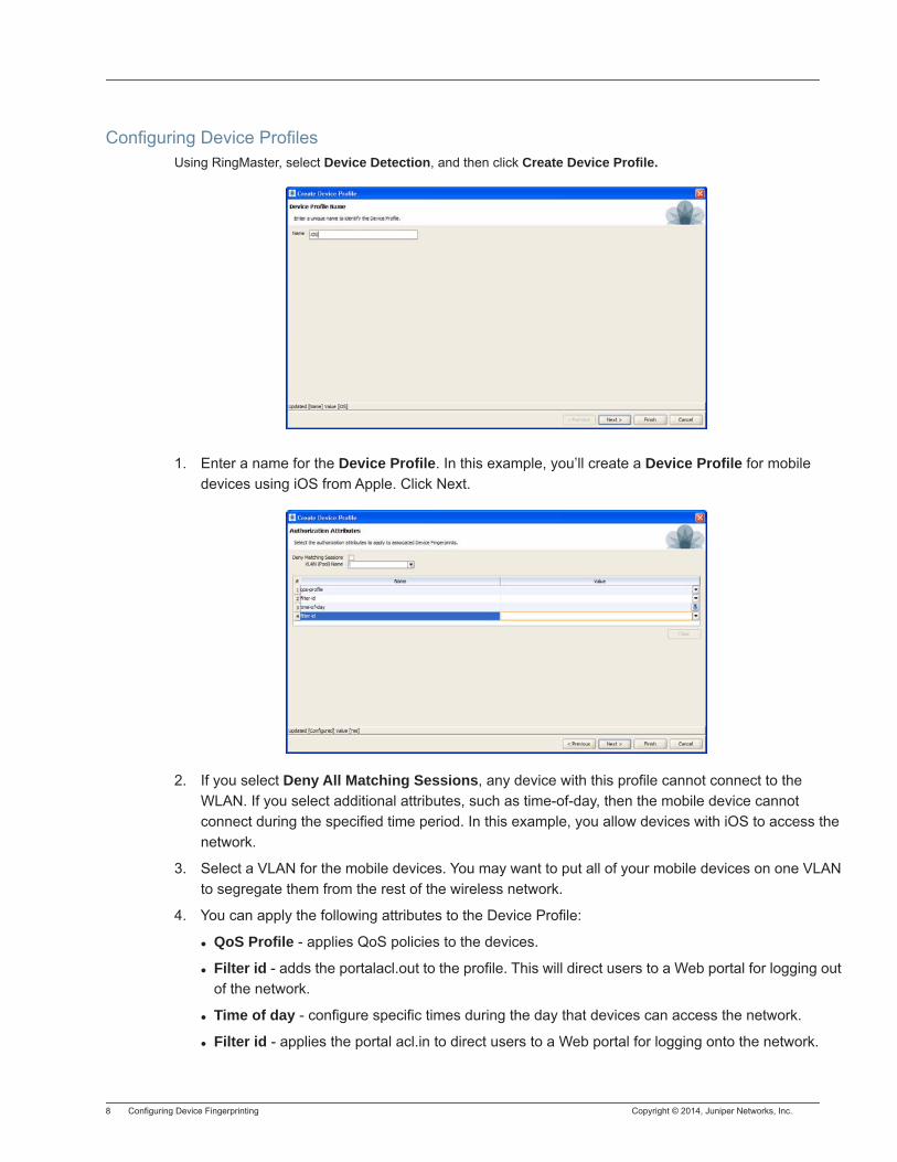
8 Configuring Device Fingerprinting Copyright © 2014, Juniper Networks, Inc.
Configuring Device ProfilesUsing RingMaster, select Device Detection, and then click Create Device Profile.
1. Enter a name for the Device Profile. In this example, you’ll create a Device Profile for mobile devices using iOS from Apple. Click Next.
2. If you select Deny All Matching Sessions, any device with this profile cannot connect to the WLAN. If you select additional attributes, such as time-of-day, then the mobile device cannot connect during the specified time period. In this example, you allow devices with iOS to access the network.
3. Select a VLAN for the mobile devices. You may want to put all of your mobile devices on one VLAN to segregate them from the rest of the wireless network.
4. You can apply the following attributes to the Device Profile:
QoS Profile - applies QoS policies to the devices.
Filter id - adds the portalacl.out to the profile. This will direct users to a Web portal for logging out of the network.
Time of day - configure specific times during the day that devices can access the network.
Filter id - applies the portal acl.in to direct users to a Web portal for logging onto the network.
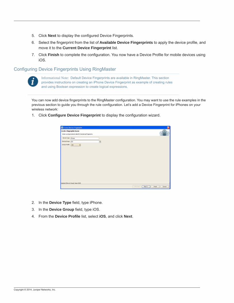
Copyright © 2014, Juniper Networks, Inc.
5. Click Next to display the configured Device Fingerprints.
6. Select the fingerprint from the list of Available Device Fingerprints to apply the device profile, and move it to the Current Device Fingerprint list.
7. Click Finish to complete the configuration. You now have a Device Profile for mobile devices using iOS.
Configuring Device Fingerprints Using RingMaster
You can now add device fingerprints to the RingMaster configuration. You may want to use the rule examples in the previous section to guide you through the rule configuration. Let’s add a Device Fingerprint for iPhones on your wireless network:
1. Click Configure Device Fingerprint to display the configuration wizard.
2. In the Device Type field, type iPhone.
3. In the Device Group field, type iOS.
4. From the Device Profile list, select iOS, and click Next.
Informational Note: Default Device Fingerprints are available in RingMaster. This section provides instructions on creating an iPhone Device Fingerprint as example of creating rules and using Boolean expression to create logical expressions.
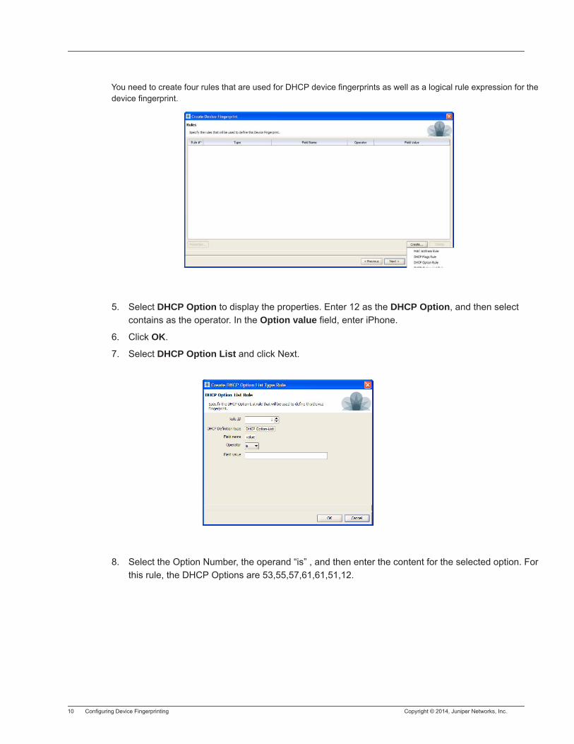
10 Configuring Device Fingerprinting Copyright © 2014, Juniper Networks, Inc.
You need to create four rules that are used for DHCP device fingerprints as well as a logical rule expression for the device fingerprint.
5. Select DHCP Option to display the properties. Enter 12 as the DHCP Option, and then select contains as the operator. In the Option value field, enter iPhone.
6. Click OK.
7. Select DHCP Option List and click Next.
8. Select the Option Number, the operand “is” , and then enter the content for the selected option. For this rule, the DHCP Options are 53,55,57,61,61,51,12.
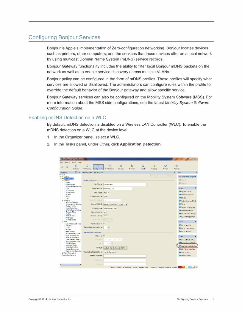
Copyright © 2014, Juniper Networks, Inc. Configuring Bonjour Services 1
Configuring Bonjour Services
Bonjour is Apple's implementation of Zero-configuration networking. Bonjour locates devices such as printers, other computers, and the services that those devices offer on a local network by using multicast Domain Name System (mDNS) service records.
Bonjour Gateway functionality includes the ability to filter local Bonjour mDNS packets on the network as well as to enable service discovery across multiple VLANs.
Bonjour policy can be configured in the form of mDNS profiles. These profiles will specify what services are allowed or disallowed. The administrators can configure rules within the profile to override the default behavior of the Bonjour gateway and allow specific service.
Bonjour Gateway services can also be configured on the Mobility System Software (MSS). For more information about the MSS side configurations, see the latest Mobility System Software Configuration Guide.
Enabling mDNS Detection on a WLCBy default, mDNS detection is disabled on a Wireless LAN Controller (WLC). To enable the mDNS detection on a WLC at the device level:
1. In the Organizer panel, select a WLC.
2. In the Tasks panel, under Other, click Application Detection.
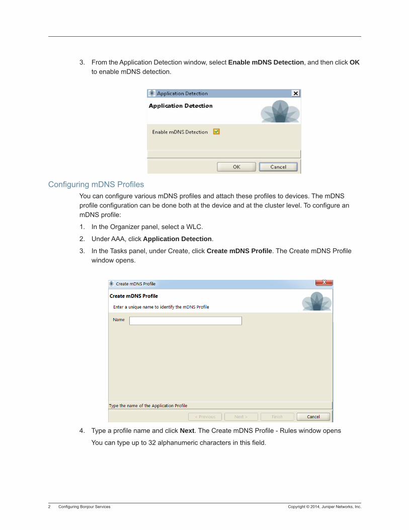
2 Configuring Bonjour Services Copyright © 2014, Juniper Networks, Inc.
3. From the Application Detection window, select Enable mDNS Detection, and then click OK to enable mDNS detection.
Configuring mDNS ProfilesYou can configure various mDNS profiles and attach these profiles to devices. The mDNS profile configuration can be done both at the device and at the cluster level. To configure an mDNS profile:
1. In the Organizer panel, select a WLC.
2. Under AAA, click Application Detection.
3. In the Tasks panel, under Create, click Create mDNS Profile. The Create mDNS Profile window opens.
4. Type a profile name and click Next. The Create mDNS Profile - Rules window opens
You can type up to 32 alphanumeric characters in this field.
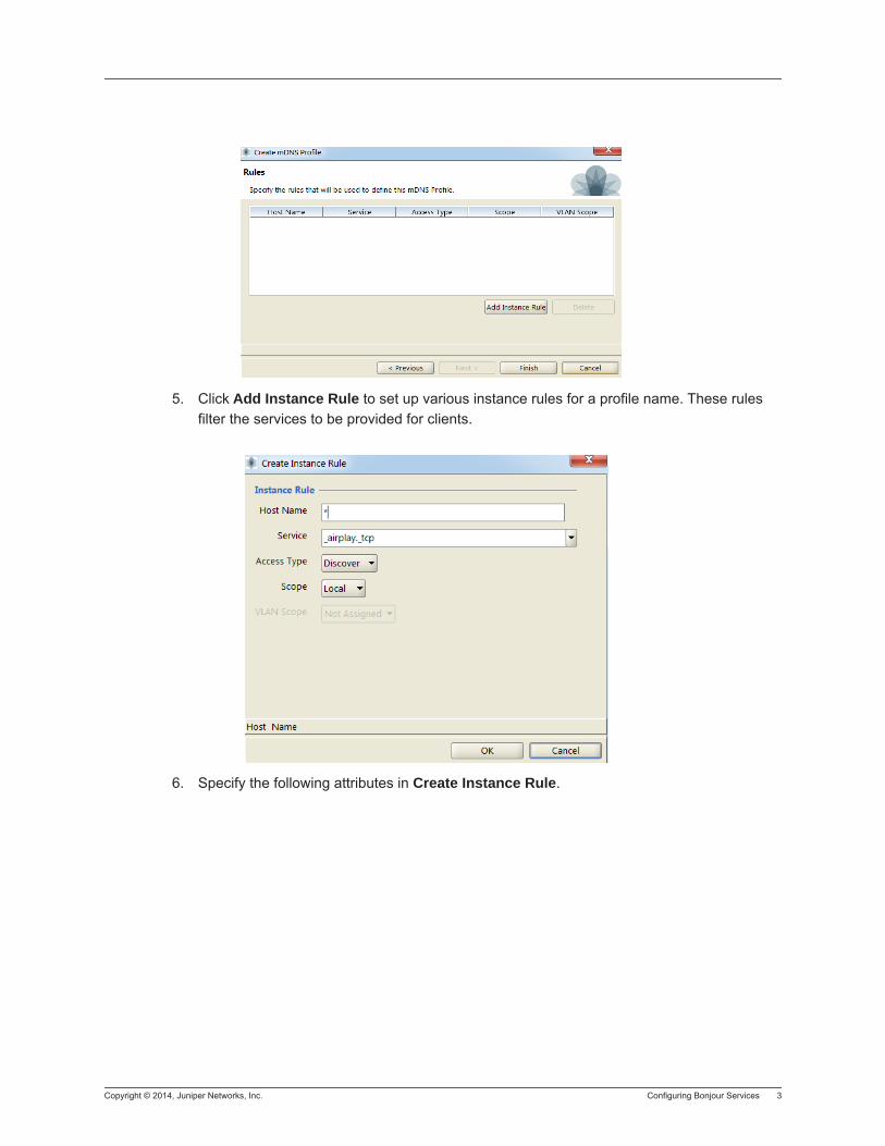
Copyright © 2014, Juniper Networks, Inc. Configuring Bonjour Services 3
5. Click Add Instance Rule to set up various instance rules for a profile name. These rules filter the services to be provided for clients.
6. Specify the following attributes in Create Instance Rule.
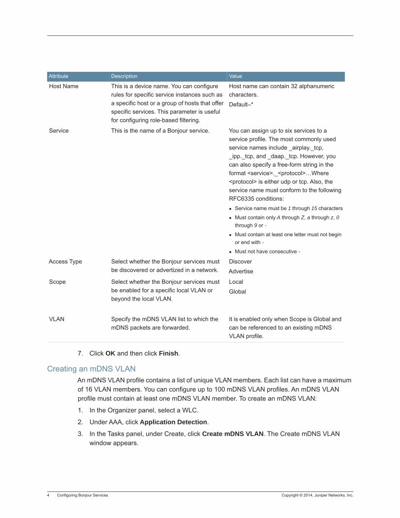
4 Configuring Bonjour Services Copyright © 2014, Juniper Networks, Inc.
7. Click OK and then click Finish.
Creating an mDNS VLANAn mDNS VLAN profile contains a list of unique VLAN members. Each list can have a maximum of 16 VLAN members. You can configure up to 100 mDNS VLAN profiles. An mDNS VLAN profile must contain at least one mDNS VLAN member. To create an mDNS VLAN:
1. In the Organizer panel, select a WLC.
2. Under AAA, click Application Detection.
3. In the Tasks panel, under Create, click Create mDNS VLAN. The Create mDNS VLAN window appears.
Attribute Description Value
Host Name This is a device name. You can configure rules for specific service instances such as a specific host or a group of hosts that offer specific services. This parameter is useful for configuring role-based filtering.
Host name can contain 32 alphanumeric characters.
Default–*
Service This is the name of a Bonjour service. You can assign up to six services to a service profile. The most commonly used service names include _airplay._tcp, _ipp._tcp, and _daap._tcp. However, you can also specify a free-form string in the format <service>._<protocol>…Where <protocol> is either udp or tcp. Also, the service name must conform to the following RFC6335 conditions:
Service name must be 1 through 15 characters
Must contain only A through Z, a through z, 0 through 9 or -
Must contain at least one letter must not begin or end with -
Must not have consecutive -
Access Type Select whether the Bonjour services must be discovered or advertized in a network.
Discover
Advertise
Scope Select whether the Bonjour services must be enabled for a specific local VLAN or beyond the local VLAN.
Local
Global
VLAN Specify the mDNS VLAN list to which the mDNS packets are forwarded.
It is enabled only when Scope is Global and can be referenced to an existing mDNS VLAN profile.
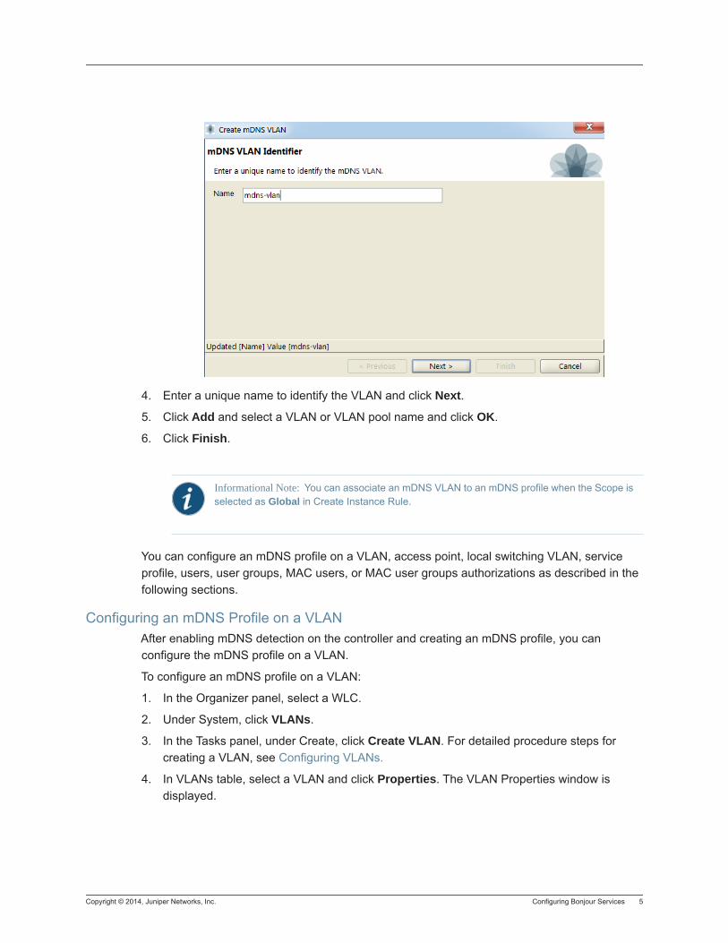
Copyright © 2014, Juniper Networks, Inc. Configuring Bonjour Services 5
4. Enter a unique name to identify the VLAN and click Next.
5. Click Add and select a VLAN or VLAN pool name and click OK.
6. Click Finish.
You can configure an mDNS profile on a VLAN, access point, local switching VLAN, service profile, users, user groups, MAC users, or MAC user groups authorizations as described in the following sections.
Configuring an mDNS Profile on a VLANAfter enabling mDNS detection on the controller and creating an mDNS profile, you can configure the mDNS profile on a VLAN.
To configure an mDNS profile on a VLAN:
1. In the Organizer panel, select a WLC.
2. Under System, click VLANs.
3. In the Tasks panel, under Create, click Create VLAN. For detailed procedure steps for creating a VLAN, see Configuring VLANs.
4. In VLANs table, select a VLAN and click Properties. The VLAN Properties window is displayed.
Informational Note: You can associate an mDNS VLAN to an mDNS profile when the Scope is selected as Global in Create Instance Rule.
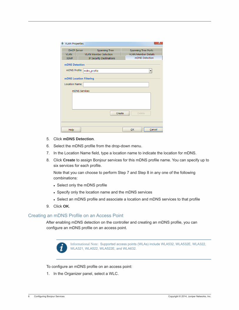
6 Configuring Bonjour Services Copyright © 2014, Juniper Networks, Inc.
5. Click mDNS Detection.
6. Select the mDNS profile from the drop-down menu.
7. In the Location Name field, type a location name to indicate the location for mDNS.
8. Click Create to assign Bonjour services for this mDNS profile name. You can specify up to six services for each profile.
Note that you can choose to perform Step 7 and Step 8 in any one of the following combinations:
Select only the mDNS profile
Specify only the location name and the mDNS services
Select an mDNS profile and associate a location and mDNS services to that profile
9. Click OK.
Creating an mDNS Profile on an Access PointAfter enabling mDNS detection on the controller and creating an mDNS profile, you can configure an mDNS profile on an access point.
To configure an mDNS profile on an access point:
1. In the Organizer panel, select a WLC.
Informational Note: Supported access points (WLAs) include WLA532, WLA532E, WLA322, WLA321, WLA522, WLA522E, and WLA632.
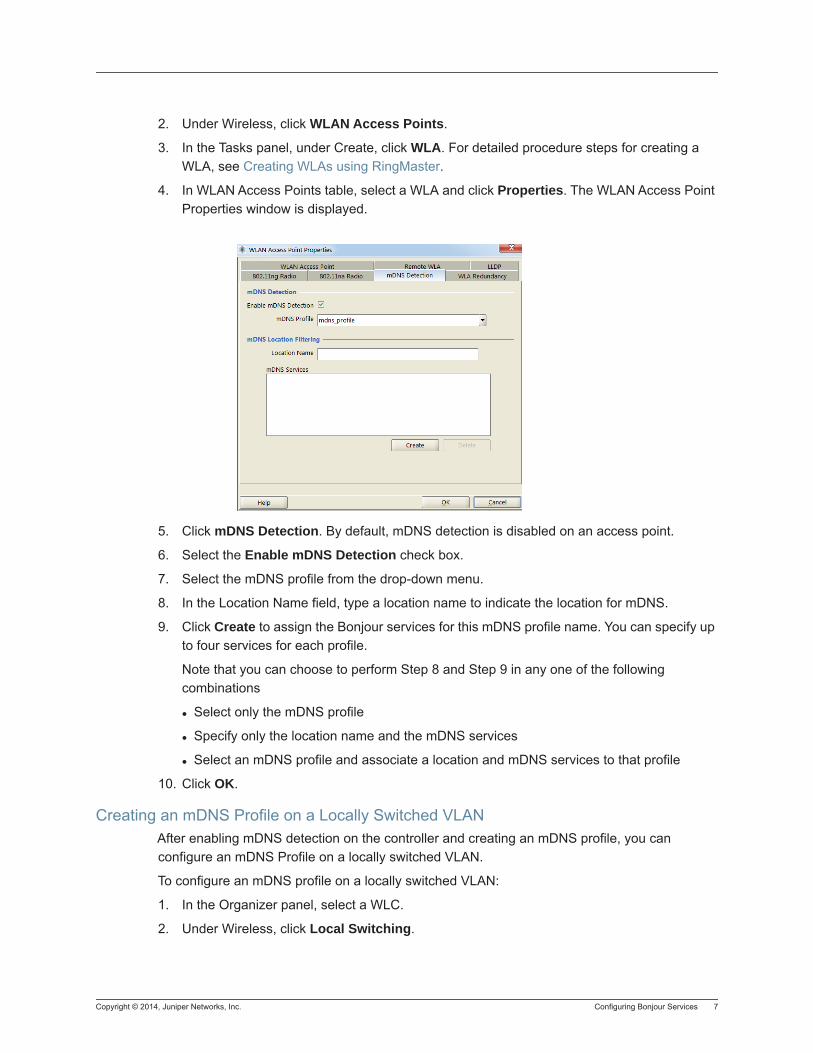
Copyright © 2014, Juniper Networks, Inc. Configuring Bonjour Services 7
2. Under Wireless, click WLAN Access Points.
3. In the Tasks panel, under Create, click WLA. For detailed procedure steps for creating a WLA, see Creating WLAs using RingMaster.
4. In WLAN Access Points table, select a WLA and click Properties. The WLAN Access Point Properties window is displayed.
5. Click mDNS Detection. By default, mDNS detection is disabled on an access point.
6. Select the Enable mDNS Detection check box.
7. Select the mDNS profile from the drop-down menu.
8. In the Location Name field, type a location name to indicate the location for mDNS.
9. Click Create to assign the Bonjour services for this mDNS profile name. You can specify up to four services for each profile.
Note that you can choose to perform Step 8 and Step 9 in any one of the following combinations
Select only the mDNS profile
Specify only the location name and the mDNS services
Select an mDNS profile and associate a location and mDNS services to that profile
10. Click OK.
Creating an mDNS Profile on a Locally Switched VLANAfter enabling mDNS detection on the controller and creating an mDNS profile, you can configure an mDNS Profile on a locally switched VLAN.
To configure an mDNS profile on a locally switched VLAN:
1. In the Organizer panel, select a WLC.
2. Under Wireless, click Local Switching.
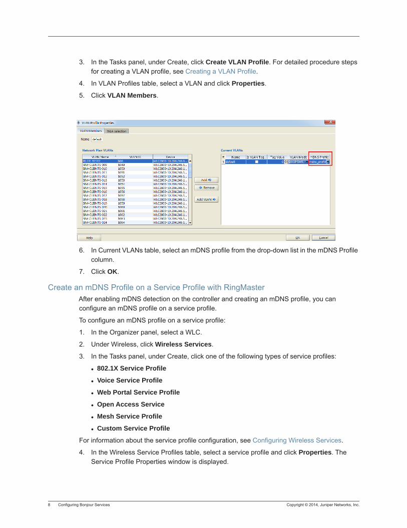
8 Configuring Bonjour Services Copyright © 2014, Juniper Networks, Inc.
3. In the Tasks panel, under Create, click Create VLAN Profile. For detailed procedure steps for creating a VLAN profile, see Creating a VLAN Profile.
4. In VLAN Profiles table, select a VLAN and click Properties.
5. Click VLAN Members.
6. In Current VLANs table, select an mDNS profile from the drop-down list in the mDNS Profile column.
7. Click OK.
Create an mDNS Profile on a Service Profile with RingMasterAfter enabling mDNS detection on the controller and creating an mDNS profile, you can configure an mDNS profile on a service profile.
To configure an mDNS profile on a service profile:
1. In the Organizer panel, select a WLC.
2. Under Wireless, click Wireless Services.
3. In the Tasks panel, under Create, click one of the following types of service profiles:
802.1X Service Profile
Voice Service Profile
Web Portal Service Profile
Open Access Service
Mesh Service Profile
Custom Service Profile
For information about the service profile configuration, see Configuring Wireless Services.
4. In the Wireless Service Profiles table, select a service profile and click Properties. The Service Profile Properties window is displayed.
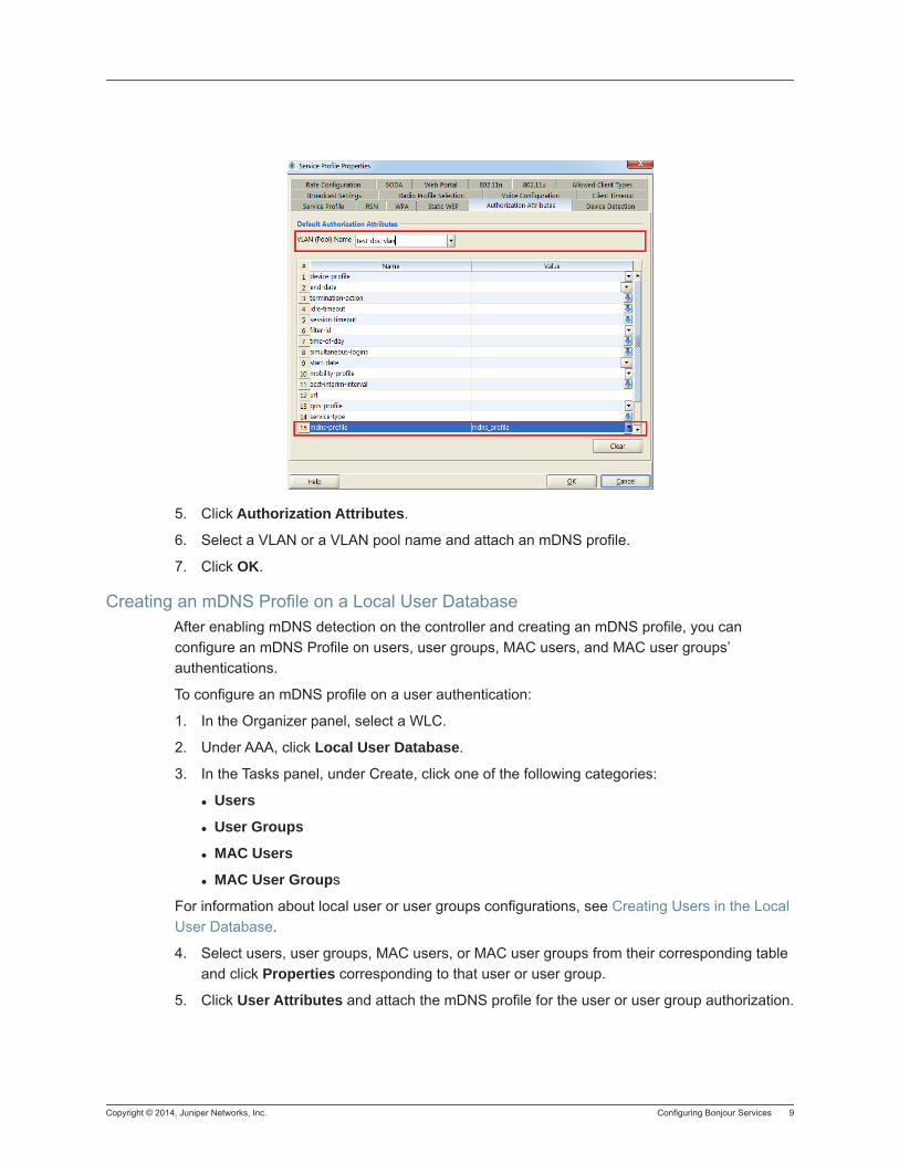
Copyright © 2014, Juniper Networks, Inc. Configuring Bonjour Services 9
5. Click Authorization Attributes.
6. Select a VLAN or a VLAN pool name and attach an mDNS profile.
7. Click OK.
Creating an mDNS Profile on a Local User DatabaseAfter enabling mDNS detection on the controller and creating an mDNS profile, you can configure an mDNS Profile on users, user groups, MAC users, and MAC user groups’ authentications.
To configure an mDNS profile on a user authentication:
1. In the Organizer panel, select a WLC.
2. Under AAA, click Local User Database.
3. In the Tasks panel, under Create, click one of the following categories:
Users
User Groups
MAC Users
MAC User Groups
For information about local user or user groups configurations, see Creating Users in the Local User Database.
4. Select users, user groups, MAC users, or MAC user groups from their corresponding table and click Properties corresponding to that user or user group.
5. Click User Attributes and attach the mDNS profile for the user or user group authorization.

10 Configuring Bonjour Services Copyright © 2014, Juniper Networks, Inc.
Copyright © 2014, Juniper Networks, Inc. 1
Integrating a WLM1200-SP into RingMaster
Integrating a WLM1200-SP into RingMaster
With the release of RingMaster 7.5 and later, you can integrate your WLM1200-SP (SmartPass) server into RingMaster and use RingMaster to manage your WLM1200-SP server.
To integrate SmartPass into RingMaster, follow these steps:
1. In RingMaster, select your Network Plan.
2. From the Organizer panel, select Application Servers.
3. From the Tasks panel, select Create SmartPass Server.
4. To configure the SmartPass Server Connection Settings, you need the following information:
Server Name
IP Address
Port Number
Username
Password
5. Once you have entered the appropriate information, RingMaster sends a synchronization request to the SmartPass server.
6. The SmartPass server is now managed by RingMaster and displayed in the list of SmartPass Servers.
7. To configure the server settings, select it from the list and click Properties.
8. Adjust the necessary settings and click Ok to save the configuration.
9. After adding the SmartPass Server, and you synchronize the server with RingMaster successfully, additional tasks are now available in RingMaster. These are the same tasks available in a standalone installation of SmartPass. You can refer to the SmartPass documentation for more information on configuring these features. The following tasks are now available:
Setup
Informational Note: You must have an active SmartPass server before you can integrate it into RingMaster. RingMaster communicates with the SmartPass server to synchronize the information in SmartPass with RingMaster. If the SmartPass server is inactive, then synchronization fails with RingMaster.
Informational Note: To take advantage of the full functionality of SmartPass, install SmartPass Version 7.4.4.1 on your server. Earlier versions have less functionality than the latest version of SmartPass.
2 Copyright © 2014, Juniper Networks, Inc.
− Synchronize
− Edit SmartPass Server
− Shared Key
Other
− Server Settings
− RADIUS Client Settings
− Web Portal Management
− User Management
− User Type Management
Clicking on any of the tasks under Other opens the current installation of SmartPass.
Copyright © 2014, Juniper Networks, Inc. Integrating a WMS1200-LA to RingMaster 3
Integrating a WMS1200-LA to RingMaster
To add an WMS1200-LA to RingMaster, you must install an WMS1200-LA in your wiring closet or located somewhere in your network. After installation, you need the following information to add the WMS1200-LA to RingMaster:
IP Address
User Name
Password
You also need a Location Appliance license in order to activate the feature in RingMaster. After installing the license, the Create Location Server task is available in the RingMaster interface.
To add an WMS1200-LA to RingMaster, follow these steps:
1. Open RingMaster and click Configuration from the menu bar.
2. From the Organizer panel, select Application Servers.
3. From the Task list, select Create Location Server and the associated wizard opens.
4. Select Managed to allow RingMaster to manage the location appliance.
5. In the Name field, enter the name of the WMS1200-LA.
6. Enter the IP address.
7. Enter the User Name.
8. Enter the Password.
9. If there is a management password, enter the password in the Management Password field.
10. Click Next. RingMaster connects to the WMS1200-LA and establishes a connection.
11. Click Finish to complete the configuration.
12. The WMS1200-LA now appears in the Organizer panel under Application Servers.
13. To review WMS1200-LA settings, highlight the Location Appliance in the list and click Properties. You can then change any of the original settings for the server.
Available Tasks for All Managed WMS1200-LA Location AppliancesThere is a list of available tasks for all location appliances managed by RingMaster. You can select any of the following tasks:
Create Location Server
Setup Synchronization Parameters
Edit a Location Server
Configure a Snoop Filter
Configure SNMP Settings
From the Other List, you can select from the following tasks:
Platform Management
Appliance Logs
4 Integrating a WMS1200-LA to RingMaster Copyright © 2014, Juniper Networks, Inc.
Backup and Restore
Configuration
Factory Reset
Schedule Reboot
System Update
User Management
Selecting any of the Other tasks opens the corresponding software feature on the location appliance. For more information on using these features, refer to the Juniper Networks WMS1200-LA User's Guide.
Available Location Appliance Tasks
If the location appliance already has a configuration, the details are displayed when you select the WMS1200-LA in the Organizer panel.
After it is selected, the following information is displayed:
Location Server
Managed
Name
Port
Version
IP Address
Locales
Name
Description
Associated Fingerprints
Associated Floor
RF Fingerprints
Name
Description
Associated Locale
In the Tasks panel, you can select from a list of available tasks. Under Create, you can select
Create Locale
Create RF Fingerprint
Under Setup, you can select
Synchronize
Edit Location Server
Snoop Filter
Copyright © 2014, Juniper Networks, Inc. Integrating a WMS1200-LA to RingMaster 5
SNMP
Under Other, you can select
Platform Management
Appliance Logs
Backup and Restore
Configuration
Factory Reset
Schedule Reboot
System Update
User Management
Selecting any tasks under Other, opens the operating system of the location appliance and you can perform any of these tasks directly on the location appliance.
Creating Locales Using RingMaster
Select an WMS1200-LA from the Application Servers list in the Organizer panel. The Task list is now populated with available tasks to perform on the location appliance. To create a locale, use the following steps:
1. Under Create, click Create Locale. The Create Locale Wizard is displayed.
2. Enter the name and description of the locale in the appropriate fields. Create RF Fingerprint is selected by default. If you do not want to create an RF Fingerprint, clear the checkbox. If you are also using Active Asset on the location appliance, you must follow a specific format for the description. The format is Campus:Building:Floor. Click Next.
3. Enter the RF Fingerprint information including Name and Description. Click Next.
4. If there are other RF Fingerprints configured on the location appliance, they are displayed in the Available RF Fingerprints list. You can select one and add it to the Current RF Fingerprints list. You can also remove RF Fingerprints by selecting one from the Current RF Fingerprints list and clicking Remove.
5. Click Finish to complete the configuration. The new locale and RF Fingerprints appear in the Location Server and RF Fingerprints section. You can view the properties of a RF Fingerprints by selecting it and then clicking Properties.
Creating Locales Using RF Planning
You can also create Locales using the RF Planning feature of RingMaster. Click RF Planning and select a plan from the Organizer. You can also import locales from CAD drawings.
1. Under Location Services, click Create Locale. The Create Locale wizard is displayed.
2. When you use the Drawing tools to draw the Locale, the Create a Locale wizard is displayed.
3. Select a Location Server from the list and click Next.
4. You can now select an existing locale or create a new locale. If you select an existing locale, click Finish to complete the configuration. If you select Create a Locale, click Next.
6 Integrating a WMS1200-LA to RingMaster Copyright © 2014, Juniper Networks, Inc.
5. Type a name and description of the Locale in the Name and Description fields. Click Finish to complete the configuration.
Adding RF Fingerprints Using RF Planning
You can add RF Fingerprints to the Locale you just created by clicking RF Fingerprint in the Task list. When you move your cursor over the locale, it changes to a crosshair. Click and drag to display the RF Fingerprint wizard.
Enter a name and description for the RF Fingerprint and click OK. The RF Fingerprint now appears on the Locale.
Calibrating RF Fingerprints Using RF Planning
1. To calibrate an RF Fingerprint, click on the fingerprint icon in the locale to select it. Then click Calibrate RF Fingerprint.
2. Enter the MAC address of the device and click Start. You can see the status in the Progress bar. Once the process is complete, you can click Next to add it to the locale.
3. Creating RF Fingerprints
4. Select an WMS1200-LA from the Application Servers list in the Organizer panel. The Task list is now populated with available tasks to perform on the location appliance. To create a RF Fingerprint, use the following steps:
5. Under Create, click Create RF Fingerprint. The wizard is displayed.
6. Enter a name and description for the RF Fingerprint.
7. Click Next.
8. Select a locale from the Associated Locale list to associate with the RF Fingerprint.
9. Click Finish to complete the configuration.
10. The RF Fingerprint now appears in the Locales list and the RF Fingerprints list.
11. Setting Up a Location Appliance Using RingMaster
12. Select an WMS1200-LA from the Application Servers list in the Organizer panel. The Task list is now populated with available tasks to perform on the location appliance.
13. Synchronizing Changes on a Location Appliance using RingMaster
14. To synchronize configurations on a location appliance, use the following steps:
15. In the Task list, click Synchronize.
16. The Review Changes panel is displayed.
17. You can select from two types of action:
18. Deploy Changes to the location appliance - changes made using RingMaster are applied to the location appliance.
19. Accept Changes from the location appliance - changes made on the location appliance are uploaded to RingMaster.
20. You cannot undo this operation. Once you click Next, the changes are synchronized between RingMaster and the LA-200.
Copyright © 2014, Juniper Networks, Inc. Integrating a WMS1200-LA to RingMaster 7
21. Click Next. The changes are synchronized between RingMaster and the location appliance.
22. Click Finish to complete the operation.
The WMS1200-LA image created using RingMaster is transferred to the WMS1200-LA where it is used by other applications such as Active Asset. It is recommended that you create a backup of your current image before transferring the new on to the WMS1200-LA.
Editing Location Appliance Attributes Using RingMaster
To edit a location appliance, select it from the list of Application Servers. Then follow these steps:
1. Click Edit Location Server to display the attributes for the server.
2. You can modify any of the listed attributes, and click Next.
3. RingMaster establishes a connection with the location appliance.Click Finish to send the changes to the location appliance.
4. Configuring a Snoop Filter for a Location Appliance
5. You can configure a snoop filter on a WLC using RingMaster and apply it to a location appliance. To configure a snoop filter, follow these steps:
6. In the Task list, under Setup, click Snoop Filter.
7. Select a WLC to target from the Select a WLC list.
8. Click Next.
9. If there is an existing Snoop Filter on the WLC, you can select it from the Filters list. If a Snoop Filter is not configured, you can select Create a Filter. Click Next.e Snoop Filter Name field, enter a name for the filter. Select Enabled to begin using the filter. Click Next.
10. Configure the Snoop Filter Observer. You must specify the following information:
Target IP Address
Snap Length Limit (optional)
Frame Gap Limit (optional)
11. Click Next.
12. Optionally, you can create Snoop Filter Conditions by specifying a list of conditions that match the criteria for packets. The following conditions can be added to the Snoop Filter:
Direction
Frame Type
Channel
BSSID
Source MAC
Destination MAC
Host MAC
MAC Pair
8 Integrating a WMS1200-LA to RingMaster Copyright © 2014, Juniper Networks, Inc.
13. When you select a condition, a list of attributes is displayed that can be applied to it. Click Next.
14. You can also configure optional Snoop Mapping by selecting radios on an MP to map the Snoop Filter. Click Next.
15. Additionally, you can map a Snoop Filter to a specific radio profile. Select one from the Available Radio Profiles list and click Add to move it into the Current Radio Profiles list.
16. Click Finish to complete the Snoop Filter configuration.
Configuring SNMP for a Location Appliance
You can configure SNMP settings for the Location Appliance using the RingMaster interface. Select a Location Appliance from the list in the Organizer panel and then click SNMP.
You need the following information to configure SNMP targets on the Location Appliance:
Destination Host
Destination Port
SNMP Version
If you select SNMP Version v2c, then you configure the SNMPv2c Settings. If you select SNMPv3, then you configure the SNMPV3 settings. Click Next to continue with the configuration.
If you a secondary SNMP target, you can configure it by entering the appropriate information. Click Finish to complete the configuration.
All tasks listed under Other are performed on the WMS1200-LA using the WMS1200-LA user interface. Consult the documentation for the WMS1200-LA to perform any of these tasks. Coverage of these tasks is beyond the scope of this document.
Monitoring the WMS1200-LA
You can see the following status information on the WMS1200-LA when you click Monitoring and then select the WMS1200-LA from the Organizer panel.
The Monitor feature displays the following information:
Status Summary — click Details for more information.
Appliance Name
Status
Admin Status
IP Address
Server Type
Management Port
Version
Up Time
Alarm Summary — click Details for more information.
Clients by Locale — you can also click Find Clients to search for clients on the network.
Copyright © 2014, Juniper Networks, Inc. Integrating a WMS1200-LA to RingMaster 9
Tracked Devices by Type
Additional WMS1200-LA Areas Monitored by RingMaster
There are additional features on the WMS1200-LA that can be monitored by RingMaster. When you select a floor with a WMS1200-LA, a new Show Devices task is available. This task displays all the devices tracked by the WMS1200-LA including:
Clients
Tags
WLAs
Rogue WLAs
You can filter the devices displayed using the following strings:SSID
User Name
MAC Address
IP Address
End Address for SIP
Radio Technology
When you use the filtering capabilities, only the devices matching the filter are displayed. Once you clear the criteria, all devices are displayed again.
You can also hide or display the following items on the Monitoring interface:
Locales
Fingerprints
WLAs
Clients (Voice and Data)
Tags
Rogue WLAs
Client and WLA Connections
When you select Show Devices and then select an asset tag, you can see the temperature of the tag as well as the battery life for the tag.
Configuring NAS-ID for an MP Using the CLI
To set the NAS-ID of an MP, use the following command:WLC# set ap apnum ap-nas-id string
The maximum length of the string value is 24 hexadecimal characters.
To set the URL format, use the following command:WLC# set service-profile profilename web-redirect-url-format [standard |cmcc]
To set the NAS-ID for the WLC as a RADIUS attribute, use the following command:WLC# set radius nas-id string
The maximum length of the string value is 24 hexadecimal characters.
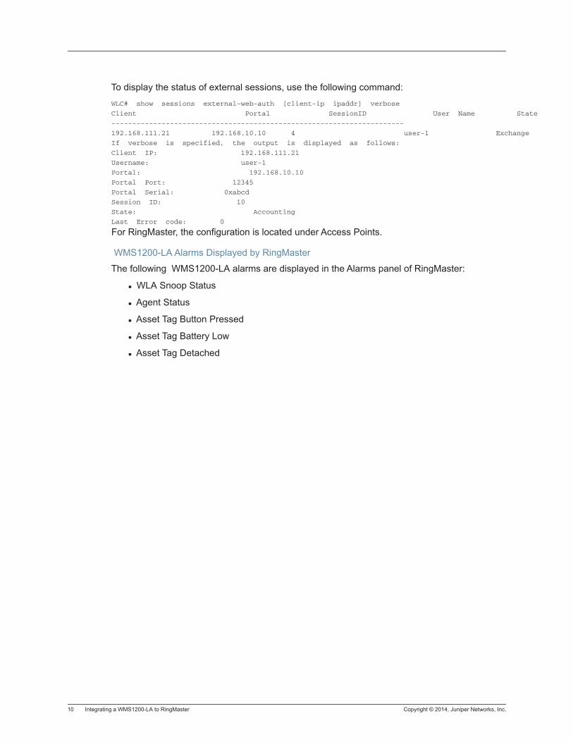
10 Integrating a WMS1200-LA to RingMaster Copyright © 2014, Juniper Networks, Inc.
To display the status of external sessions, use the following command:WLC# show sessions external-web-auth [client-ip ipaddr] verbose
Client Portal SessionID User Name State
----------------------------------------------------------------------
192.168.111.21 192.168.10.10 4 user-1 Exchange
If verbose is specified, the output is displayed as follows:
Client IP: 192.168.111.21
Username: user-1
Portal: 192.168.10.10
Portal Port: 12345
Portal Serial: 0xabcd
Session ID: 10
State: Accounting
Last Error code: 0
For RingMaster, the configuration is located under Access Points.
WMS1200-LA Alarms Displayed by RingMaster
The following WMS1200-LA alarms are displayed in the Alarms panel of RingMaster:
WLA Snoop Status
Agent Status
Asset Tag Button Pressed
Asset Tag Battery Low
Asset Tag Detached
Copyright © 2014, Juniper Networks, Inc. Integrating an AirTight Server into RingMaster 11
Integrating an AirTight Server into RingMaster
OverviewSpectraGuard Enterprise is a complete, end-to-end wireless intrusion prevention solution (WIPS) used by some of the world’s largest enterprise firms. You can now add AirTight servers to your RingMaster configuration. AirTight is a wireless security system that can track unwanted access or attempts to access your wireless network. For more information on AirTight, see the Web site at http://www.airtightneworks.com.
Adding the AirTight Server to RingMaster1. After you log into RingMaster, click Configuration. In the Organizer panel, select Application
Servers.
2. The options for Application Server are displayed in the Tasks panel. Click Create AirTight SGD Server to launch the configuration wizard.
3. Enter the configuration information into the following fields:
Name — The name of the AirTight server
IP Address — Enter the IP Address of the AirTight server.
Username — The username required to authenticate on the server.
Password — The password required to complete the authentication process on the server.
4. If you are not enabling SNMP for the AirTight server, clear Enable Traps. It is selected by default.
5. Click Next.
6. RingMaster now attempts to connect to the AirTight SGE server and synchronize with it.
7. After RingMaster synchronizes with the AirTight server, click Next to continue the integration.
8. You can now configure SNMP on RingMaster to process traps from the AirTight SGE Server. Select the SNMP version from the list and then configure the v2c settings.
9. Click Next to complete the configuration. The AirTight Server is now displayed in the Security Servers section of the Application Servers page.
10. To edit the AirTight Server properties, select the AirTight SGE Server and click Properties. You can edit the same information that you configured using the wizard.
Informational Note: Before you can integrate an AirTight Server, you must purchase and install the RingMaster license, RMTS-SECURITY-ADV.
Informational Note: Because AirTight uses a proprietary configuration for SNMP, you cannot configure SNMP Version 3 as the SNMP setting.
12 Integrating an AirTight Server into RingMaster Copyright © 2014, Juniper Networks, Inc.
For specific information about AirTight SGE Server and its configuration, please consult the AirTightSGE Server documentation.
Adding Alarms for the AirTight Application ServerYou can configure RingMaster to display alarms for the AirTight application server. To add or remove alarm categories, follow these steps:
1. Click Alarms, and then Setup.
2. Click the AirTight SGE Settings tab.
3. All AirTight alarms are enabled by default. Clear checkboxes next to the alarms that you do not want monitored.
4. Click Close to save your alarm settings.
5. You can also query the Alarms database for AirTight-specific alarms. Click Query, and then select Security Server from the Type list.
6. From the Instance list, select Application Servers: AirTight.
7. Select the date and time range for the query.
8. Then select the Categories, Severities, and the States.
9. Click OK to execute the query against the Alarm database.
Creating AirTight Reports Using RingMasterYou can create AirTight reports by clicking on Reports in the RingMaster interface, and then clicking Report under Generate in the Task list.
1. From the Organizer list, select Alarms and then Alarm Summary.
2. From the Task list, under Generate, click Report.
3. From the Report Scope Type list, select Security Server.
4. Click Next.
5. Select the type of format for the report from the Report Format list. Also, specify an e-mail address if you want the report sent via e-mail. Then specify if you want the report sent as a hyperlink in the e-mail or attached as a PDF.
You can also copy the report to an FTP server. You must configure the FTP server as part of the overall Report Settings located under Setup in the Tasks list.
6. When you click Next, a link is generated to the report.
7. When you click on the link, the Alarm Summary Report is displayed in your Web browser.
Copyright © 2014, Juniper Networks, Inc. Overview 1
Policies Configuration
Policies Configuration
Overview
A policy is a set of WLC configuration parameters defined in RingMaster and then applied to multiple WLCs. When you apply a policy to a set of WLCs, all parameter settings in the policy are applied to the WLCs and update previous settings on these WLCs.
Managing Changes
When you create a new policy, none of the settings for the policy are applied to WLC switches (even the ones you associate with the policy when you create it), until you explicitly apply the policy to the switches.
After associating a new policy with a switch, all new switches that match the WLA model and version number of the policy automatically receive the parameter settings in the policy. New switches are switches created using the WLC Switch wizard or any uploaded switches. However, policy changes are not automatically applied to switches. Reapply the changed policy to associated switches after making any changes to the policy.
Example of a Policy for a Large Network Deployment
In some cases, large network deployments consist of multiple instances of the same WLC models. A policy can be created in RingMaster and applied to the same modes without configuring the individual controllers.
For example, you may want to apply the same AAA parameters or wireless profile parameters to all WLC800s in your network. By creating a policy that is applied to all WLC800s, the policy is automatically applied by default when new WLC800s are added to the network.
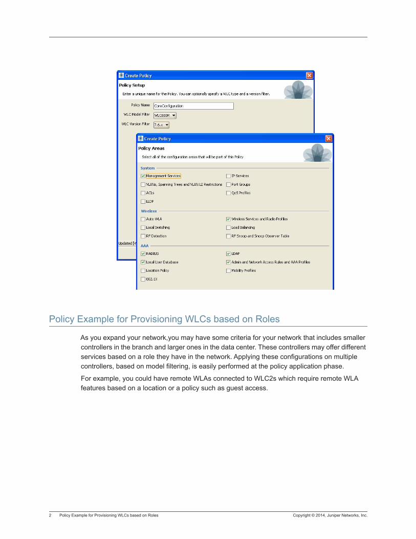
2 Policy Example for Provisioning WLCs based on Roles Copyright © 2014, Juniper Networks, Inc.
Policy Example for Provisioning WLCs based on Roles
As you expand your network,you may have some criteria for your network that includes smaller controllers in the branch and larger ones in the data center. These controllers may offer different services based on a role they have in the network. Applying these configurations on multiple controllers, based on model filtering, is easily performed at the policy application phase.
For example, you could have remote WLAs connected to WLC2s which require remote WLA features based on a location or a policy such as guest access.
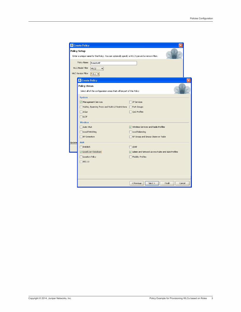
Copyright © 2014, Juniper Networks, Inc. Policy Example for Provisioning WLCs based on Roles 3
Policies Configuration

4 Policy Example for Provisioning WLCs based on Roles Copyright © 2014, Juniper Networks, Inc.
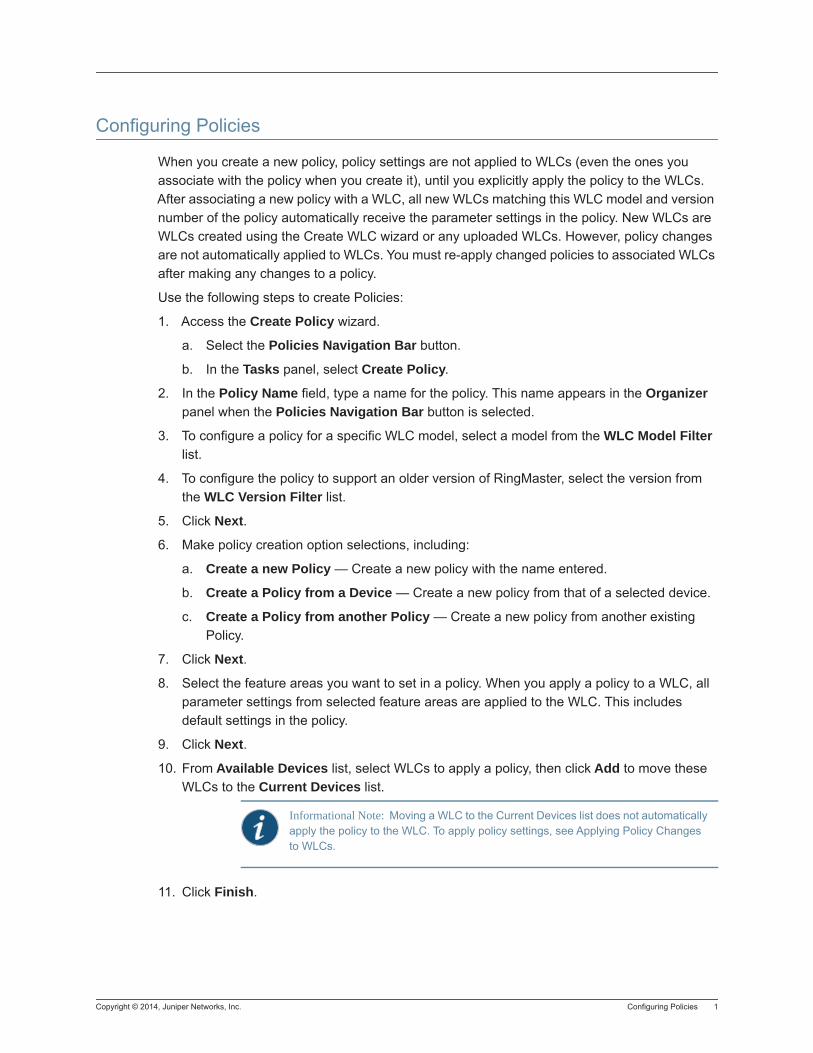
Copyright © 2014, Juniper Networks, Inc. Configuring Policies 1
Configuring Policies
When you create a new policy, policy settings are not applied to WLCs (even the ones you associate with the policy when you create it), until you explicitly apply the policy to the WLCs. After associating a new policy with a WLC, all new WLCs matching this WLC model and version number of the policy automatically receive the parameter settings in the policy. New WLCs are WLCs created using the Create WLC wizard or any uploaded WLCs. However, policy changes are not automatically applied to WLCs. You must re-apply changed policies to associated WLCs after making any changes to a policy.
Use the following steps to create Policies:
1. Access the Create Policy wizard.
a. Select the Policies Navigation Bar button.
b. In the Tasks panel, select Create Policy.
2. In the Policy Name field, type a name for the policy. This name appears in the Organizer panel when the Policies Navigation Bar button is selected.
3. To configure a policy for a specific WLC model, select a model from the WLC Model Filter list.
4. To configure the policy to support an older version of RingMaster, select the version from the WLC Version Filter list.
5. Click Next.
6. Make policy creation option selections, including:
a. Create a new Policy — Create a new policy with the name entered.
b. Create a Policy from a Device — Create a new policy from that of a selected device.
c. Create a Policy from another Policy — Create a new policy from another existing Policy.
7. Click Next.
8. Select the feature areas you want to set in a policy. When you apply a policy to a WLC, all parameter settings from selected feature areas are applied to the WLC. This includes default settings in the policy.
9. Click Next.
10. From Available Devices list, select WLCs to apply a policy, then click Add to move these WLCs to the Current Devices list.
11. Click Finish.
Informational Note: Moving a WLC to the Current Devices list does not automatically apply the policy to the WLC. To apply policy settings, see Applying Policy Changes to WLCs.

2 Configuring Policies Copyright © 2014, Juniper Networks, Inc.
Copyright © 2014, Juniper Networks, Inc. Applying Policies 1
Applying Policies
1. Select Apply in the Tasks panel to apply the changes to WLCs associated with a policy.
2. Review the list of WLCs, then click Apply. These changes are automatically applied to WLCs associated with the policy.
3. After the task is complete, click Close.
4. Repeat step 2 through step 3 for each policy category.

2 Applying Policies Copyright © 2014, Juniper Networks, Inc.
Copyright © 2014, Juniper Networks, Inc. 1
Verifying Configuration Changes
Verifying Configuration Changes
RingMaster employs a set of rules to verify WLC configurations. Changes to a WLC configuration in RingMaster or in a network are evaluated by comparing changes to rules. If this evaluation detects error or warning conditions, the Alerts panel is updated:
Errors or warnings on a WLC configuration in RingMaster affect Configuration counts.
Errors or warnings on the network affect Alarm counts.
Viewing the Verification PanelClick on the word Config: (error list) in the Alerts panel to display the Verification panel, which shows errors and warnings for WLC configuration information in RingMaster. The upper section lists error descriptions in red and warning descriptions in orange:
Errors are serious problems that must be addressed before deployment. By default, you cannot deploy a network plan with errors in it. After correcting errors, verify the network plan again to verify errors have been resolved.
Warnings are non-critical issues that do not prevent deployment. Review any warnings and consider resolving the issues before deployment.
Details about selected errors or warnings appear in the lower left section of the panel.
The Resolution section lists options for resolving a warning or error.
Filtering the Message List
By default, all warning and error messages are listed. You can click on the Filter checkbox to filter a message list. You can use the State menu to make selections.
Menu choices are as follows:
(All) — All messages are listed when this option is selected.
Error — Only Error messages are listed when this option is selected.
Error (Disabled) — Only Disabled rules are listed when this option is selected.
Warning — Display only Warning messages when this option is selected.
Resolving a Warning or Error Message
For most errors and warnings, RingMaster provides a link to the configuration information that caused the error or warning. The link appears in the Resolutions section of the panel, under the Messages column. When you click the Edit link, RingMaster opens a configuration wizard for the configuration item. For example, if you create a new WLC called user-WLCr2 but you do not specify the system IP address of the WLC, the error message System IP address is not assigned or is invalid appears in the Message area. To correct the error, click on Edit user-WLCr2 in the Resolutions section. The Modify WLC wizard appears. Use the wizard to edit the System IP address. After saving this configuration change, RingMaster re-evaluates the configuration. If the system IP address is specified, the error no longer appears in the Verification panel.
Verifying Configuration Changes
2 Copyright © 2014, Juniper Networks, Inc.
To resolve an error or warning:
1. Select the error or warning message in the Message column.
2. Read the information in the Details area. For some errors and warnings, this section contains information about how to resolve the error or warning.
3. If a a hint is listed in the Resolutions section, click on the option to display the configuration wizard for that item.
4. Edit the configuration item or resolve the network issue and save the change.
5. Refresh the information in the Verification panel.
6. Verify that the message no longer appears in the Verification panel.
Disabling a Rule in the Message List
All RingMaster rules are enabled by default. If you want RingMaster to stop alerting you about a specific error or warning, you can disable the rule for that error or warning. You can disable rules on a per-instance basis or globally for all instances.
If you disable a rule for a specific instance, RingMaster stops alerting you about that particular instance but still uses the rule when evaluating other configuration items.
If you disable a rule for all instances, RingMaster stops using that rule altogether when verifying a configuration.
To disable a specific instance of a warning or error:
1. Select a warning or error message.
2. In the Resolutions section, click Disable this rule for this instance only. When you enable this option, the message disappears from the list. RingMaster does not display this particular instance of the message again.
To globally disable a warning or error:
1. Select an instance of the warning or error message.
2. In the Resolutions section, click Disable this rule for all instances. When you enable this option, all instances of the message disappear from the list. RingMaster does not display the message again.
Changing Verification Options
By default, RingMaster verifies configuration information in the following cases:
Configuration is changed in RingMaster.
Deploy or export a WLC from RingMaster to the network.
Upload a WLC from the network into RingMaster.
Informational Note: Rules that are disabled for all instances are disabled on a per-user basis, not a per-plan basis. When you disable all instances of a rule, the rule is disabled for any network plan that you open while logged on with the RingMaster Client user name used when you disabled the rule.
Copyright © 2014, Juniper Networks, Inc. 3
Verifying Configuration Changes
RingMaster verifies a WLC configuration by default each time a change occurs. In addition, it allows you to deploy or export configuration changes that cause error messages by default.
To change verification options:
1. In the Tasks panel, while viewing the Verification panel, click Edit Verification Options and the multi-tabbed Verification Options dialog box is displayed. The first tab shown is the Options tab:
2. Select the cases for RingMaster to perform verification:
Verify changes only — RingMaster performs verification only on configuration items that change, rather than the entire configuration when any change in that configuration occurs.
Verify on edits — RingMaster performs verification whenever you edit a configuration.
Verify on deploy and export — RingMaster performs verification when you select the option to deploy WLCs from RingMaster to the live network.
Verify on upload — RingMaster performs verification when you select the option to upload a configuration from the network into RingMaster.
Allow errors to be deployed and exported — RingMaster allows you to deploy or export a configuration even if it contains errors.
3. Click Close to place the changes into effect and close the dialog box.

Verifying Configuration Changes
4 Copyright © 2014, Juniper Networks, Inc.
Copyright © 2014, Juniper Networks, Inc. 1
Adding a Third Party WLA to a Network Plan
Adding a Third Party WLA to a Network Plan
You can add a third-party WLA to an equipment list of a network plan. When you use RF Planning, you can place a WLA at its location on a floor plan. In this case, RingMaster takes the channel number of the WLA into account when assigning channels to WLAs.
To add a Third Party WLA:
1. Select the Configuration Navigation Bar button.
2. Select the network plan in the Organizer panel.
3. Select the Third Party WLA task in the Tasks panel. The Create Third Party WLA wizard appears.
4. In the Name field, type a name for the access point. You can use 1 to 32 characters, with no punctuation except the following: period (.), hyphen (-), or underscore (_).
5. Optionally, in the Manufacturer ID field, type the manufacturer identification for the access point (1 to 30 characters, with no spaces).
6. In the Product ID field, type the product identification for the access point (1 to 30 characters, with no spaces).
7. In the IP Address dialog, type the IP address for the access point.
8. If you specify an IP address, you can use Telnet and a Web browser with this access point.
9. In the Telnet Port Number field, specify the port number for Telnet service.
10. In the HTTP Port Number field, specify the port number for HTTP service.
11. Click Next.
12. From the WLA Model list, select one of the following:
WLA (Dual Radio) — 802.11a and 802.11b or 802.11b/g
WLA (Single Radio) — 802.11a, 802.11b, or 802.11g
13. In the Radio Type list, select one of the following: 11a, 11b, 11g. The choices available depend on the selection you made in step 11.
14. Click Next.
15. Verify the radio slot number and radio type. For a dual-radio access point, 802.11b/g radios have a slot number of 1. 802.11a radios have a slot number of 2.
16. From the Channel Number list, select the channel number for the radio.
17. In the Transmit Power field, specify the transmit power for the radio.
18. To enable the radio, select Enabled.
NOTE: The radio for the access point must be enabled to be considered in channel allocation.
19. In the SSID field, type the Service Set Identifier (SSID) for the radio.
20. In the MAC Address field, type the MAC address of the radio.

Adding a Third Party WLA to a Network Plan
2 Copyright © 2014, Juniper Networks, Inc.
21. From the Antenna Gain list, select the antenna gain for the radio.
22. If the access point has only one radio, click Finish. Otherwise, go to step 22.
23. Click Next. The Radio A page appears.
24. Repeat step 14 through step 20 for the 802.11a radio.
25. Click Finish to save changes.


![Juniper Networks JUNOScope IP Service Manager CONFIGURATION ... Juniper Networks JUNOScope IP Service Manager 8.2R2 provides a web based ... JUNOScope Software User Guide [j];](https://img.pdfslide.us/doc/110x75/5b0692e57f8b9a93418d0038/juniper-networks-junoscope-ip-service-manager-configuration-juniper-networks.jpg)


![[Juniper][JUNOS Internet Software Configuration Guide.getting Start.release 5.6 - 2002]](https://img.pdfslide.us/doc/110x75/577c7b8e1a28abe05497f271/juniperjunos-internet-software-configuration-guidegetting-startrelease.jpg)